

Page 1

Quick Start Guide
Agilent 86100A Wide-Bandwidth Oscilloscope
Page 2

© Copyright Agilent Technologies, Inc. 2000
All Rights Reserved. Reproduction, adaptation, or translation without prior written
permission is prohibit ed ,
except as allowed under copyright laws.
Agilent Technologies Part No.
86100-90033
Printed in USA
July 2001
Agilent Technologies, Inc.
Lightwave Division
1400 Fountaingrove Parkway
Santa Rosa, CA 95403-1799,
USA
Notice.
The information contained in
this document is subject to
change without notice. Companies, names, and data used
in examples herein are fictitious unless otherwise noted.
Agilent Technologies makes
no warranty of any kind with
regard to this material, including but not limited to, the
implied warranties of merchantability and fitness for a
particular purpose. Agilent
Technologies shall not be liable for errors contained herein
or for incidental or consequential damages in connection with the furnishing,
performance, or use of this
material.
Restricte d Ri ghts Legend .
Use, duplication, or disclosure by the U.S. Government
is subject to res tric tio ns as se t
forth in subparagraph (c) (1)
(ii) of the Rights in Technical
Data and Computer Software
clause at DFARS 252. 227-7013
for DOD agencies, and subparagraphs (c) ( 1) and (c) (2 )
of the Commercial Computer
Software Restricted Rights
clause at FAR 52.227-19 for
other agencies.
Warranty.
This Agilent Technologies
instrument product is warranted against defects in
material and workmanship for
a period of one year from date
of shipment. During the warranty period, Agilent Technologies Company will, at its
option, either repair or
replace products which prove
to be defective. For warranty
service or repair, this product
must be returned to a service
facility designated by Agilent
Technologies. Buyer shall prepay shipping charges to Agilent Technologies and Agilent
Technologies shall pay shipping charges to return the
product to Buyer. However,
Buyer shall pay all shipping
charges, duties, and taxes for
products returned to Agilent
Technologies from another
country.
Agilent Technologies warrants that its software and
firmware designated by Agilent Technologies for use with
an instrument will execute its
programming instructions
when properly installed on
that instrument. Agilent Technologies does not warrant that
the operation of the instrument, or software, or firmware
will be uninterrupted or errorfree.
Limitation of Warranty.
The foregoing warranty shall
not apply to defects resulting
from improper or inadequate
maintenance by Buyer, Buyersupplied software or interfacing, unauthorized modification or misuse, ope ra tio n
outside of the environmental
specifications for the product,
or improper site preparation
or maintenance.
No other warranty is
expressed or implied. Agilent
Technologies specifically disclaims the implied warranties
of merchantability and fitness
for a particular purpose.
Exclusive Remedies.
The remedies provided herein
are buyer's sole and exclusive
remedies. Agilent Technologies shall not be liable for any
direct, indirect, special, incidental, or consequential damages, whether based on
contract, tort, or any other
legal theory.
Safety Symbols.
CAUTION
The caution sign denotes a
hazard. It calls attenti on to a
procedure which, if not correctly performed or adhered
to, could result in damage to
or destruction of the product.
Do not proceed beyond a caution sign until the indicated
conditions are fully understood and met.
WARNING
The warning sign denotes a
hazard. It calls attenti on to a
procedure which, if not correctly performed or adhered
to, could result in injury or
loss of life. Do not proceed
beyond a warning sign until
the indicated conditions are
fully understood and met.
The instruction manual symbol. The product is marked wit h this
warning symbol when
it is necessary for the
user to refer to the
instructions in the
manual.
The laser radiation
symbol. This warning
symbol is marked on
products which have a
laser output.
The AC symbol is used
to indicate the
required nature of the
line module input
power.
| The ON symbols are
used to mark the positions of the instrum ent
power line switch.
The OFF symbols
are used to mark the
positions of the instrument power line
switch.
The CE mark is a registered trademark of
the European Community.
The CSA mark is a registered trademark of
the Canadian Standards Association.
The C-Tick mark is a
registered trademark
of the Australian Spectrum Management
Agency.
This text denotes the
ISM1-A
instrument is an
Industrial Scientific
and Medical Group 1
Class A product.
ii
Page 3

In This Book
In This Book
This book gives you the information you need to begin using the Infiniium
DCA. It contains five chapters:
Chapter 1, “Setting Up the Infiniium DCA” contains inspection, power require-
ments, air flow, and set u p information.
Chapter 2, “Working in Comfort” contains recommendations for working com-
fortably and safely while operating the Infiniium DCA.
Chapter 3, “Using the Infiniium DCA” gives an overview of the front panel and
the graphical user interface, and tells you how to perform basic operations
with the Infiniium DCA.
Chapter 4, “Using the Built-In Infor m ation System” describes the built-in
information system contents and navigation. The built-in information system
contains all of the information that is gen erally found in a user’s guide.
Chapter 5, “Regulatory Information” contains important regulatory informa-
tion.
• For detailed information on how the Infiniium DCA makes measurements and
how to use the instrum e nt, see the built-i n information system in the instrument.
• For information on progra m m ing the Infiniium DCA using a computer wi th a
GPIB interfa ce card, refer to the Infiniium DCA Programmer’s Guide.
CAUTION The Infiniiu m DCA uses a specially d esigned Windo ws 98 application pro gram
(Windows ® is a U.S. registered trademark of Microsoft Corp.) All Infiniium
DCA functionality is directly available from within the Infiniium DCA
application. Windows 98 conf iguration changes made outside of the Infini iu m
DCA application may not work corr ectly and could cause the inst rum e nt to
become inoperable. Do not try to acce ss or make changes to the Windows
Operating system. Repairs caused by the improper use of the Infiniium DCA
will not be covered under warranty.
iii
Page 4

General Safety Considerations
General Safety Considerations
This product has been designed and tested in accordance with the standards
listed on the Manufacturer’s Declaration of Conformity, and has been supplied
in a safe condition. The doc um en tati o n contains information and warnin gs
that must be follo wed by t he user to ensur e safe operatio n and to mainta in the
product in a safe condition.
Install the ins trument according to the en c lo sure protection pro v ided. This
instrument does not protect against the ingress of water. This instrument protects against finger access to hazardous parts within the en clos ur e.
WARNI NG If this product is not used as specified, the protection provided by the
equipment could be impaired. This product must be used in a normal
condition (in which all means for protection are intact) only.
WARNI NG No operator serviceable parts inside. Refer servicing to qualified
service personnel. To prevent electrical shock do not remove covers.
WARNI NG To prevent electrical shock, disconnect the instrument from mains
before cleaning. Use a dry cloth or one slightly dampened with water
to clean the external case parts. Do not attemp t to clean inter nally.
CAUTION Do not use too much liquid in cleaning the instrument. Water can enter the
front-panel keyboard, damagin g se nsitive electronic components.
iv
Page 5

Contents
In This Book iii
1 Setting Up the Infiniium DCA
Installing the Infiniium DCA 1–3
Cleaning Connections for Accurate Measurements 1–29
Returning the Instrument for Service 1–38
Agilent Technologies Service Offices 1–41
2 W orking in Comf or t
3 Using the Infiniium DCA
Eye/Mask Mode 3–7
Oscilloscope Mode 3–8
TDR/TDT Mode 3–9
Using Plug-in Modules 3–10
Using the Touch Screen 3–12
Using the Quick Measure Feature 3–14
If the Display Goes Blank 3 –15
Hiding and Moving Dialog Boxes 3–16
Menus 3–17
4 Using the Built-In Information System
The Contents Topic 4–3
Using Setup Guides 4–4
Getting Help While Changing Instrument Settings 4–6
Learning About Measurem ents Results 4–7
Hiding the Built-in Information System 4–8
Printing the Content s of a Topic 4–9
Selecting the Built-in Information System Language 4–10
5 Regulatory Informa tion
Contents-1
Page 6

Contents
Contents-2
Page 7

1
Installing the Infiniium DCA 1-3
Step 1. Inspect the shipment 1-3
Step 2. Install any mod ul es 1-7
Step 3. Connect the keyboard and mous e 1-8
Step 4. Connect the line cord 1-9
Step 5. Turn on the line power 1-14
Step 6. Set the time and date 1-16
Step 7. Connect a printer 1-17
Step 8. Configure the touch screen 1-22
Step 9. Configure th e in strument on a LAN 1-24
Step 10. Avoid costly repairs 1-25
Step 11. Perf or m a vertical c a libration 1- 2 6
Step 12. For more information 1-29
Cleaning Connections for Accurate Measurements 1-30
Returning the Instrument for Service 1- 3 9
Agilent Technologies Service Offices 1-42
Setting Up the Infiniium DCA
Page 8

Setting Up the Infiniium DCA
Setting Up the Infiniium DCA
Setting Up the Infiniium DCA
This chapter shows you how to set up your Infiniium DCA and co nnect the
power and the accessories. It also shows you how to use proper optical connection cleaning techniques to avoid costly repairs.
WARNI NG This is a Safety Class 1 Product (provided with a protective earthing
ground incorporated in the power cord). The mains plug shall only be
inserted in a socket outlet provided with a protective earth contact.
Any interruption of the protective conductor inside or outside of the
instrument is likely to make the instrument dangerous. Intentional
interruption is prohi bited.
CAUTION VENTILA TION RE QUIREMENTS: When installing t he product in a cabinet, the
convection into and out of the product must not be restricted. The ambient
temperature (outside the cabinet) must be less than the maximum operating
temperatur e of the product by 4
cabinet. If the total power dissipated in the cabinet is greater than 800watts,
then forced convection must be used.
° C for every 100 watts dissipated in the
CAUTION This product i s designed for use in Insta llation Category II an d P o llution
Degree 2 per IEC 1010 and 664 respectively.
Installation Category: Installation Categor ies (overvoltage categories) are
determined by the transient overvoltage levels that may be expected. CAT I:
Mains isolated. CAT II: Line voltage in appliance and to wall outlet. CAT III:
Line voltage behi nd wall outlet to nex t le v el of distributi o n.
1-2
Page 9

Installing the Infiniium DCA
Step 1. Inspect the shipment
Setting Up the Infiniium DCA
Installing the Infiniium DCA
Inspect the shipping container for damage.
Inspect the instrume nt.
Verify that you received the options and accessories you ordered.
1-3
Page 10

Setting Up the Infiniium DCA
Step 1. Inspect the shipment
Keep the shipping container and cushioning material until you have inspected
the contents of the shipment for completeness and have checked the instrument mechanically and electrically.
If anything is missing or de fective, contact your nearest Agilent Technologies
Sales Office. Refer to “Agilent Technologies Service Offices” on page 1-42. If
the shipment was damaged, contact the carrier, then contact the nearest Agilent Sales Office. Keep the shipping materi a ls for the carrier’s inspection. The
Agilent Sales Office will arrange for repair or replacement at Agilent’s option
without waitin g fo r claim settlement.
Table 1-1. Standard Accessories
Accessory Part Number
Keyboard E2610-68700
Mouse C3751-60201
Quick Start Guide (this book) 86100-90033
Programmer’s Guide 86100-90017
Programmer’s Guide Manual Ch ange Supplement 86100-90034
APC 3.5 (f-f) 5061-5311
Table 1-2. Product Options
Option Description
001 12 GHz Trigger Bandwidth
AX4 Rack mount flange kit
AXE Rack mount flange kit with handles
UK6 Commercial calibration certificate with test data
1-4
Page 11

Table 1-3. Optional Accessories
Accessory Description
83446A Lightwave clock and data receiver
11982A High-speed lightwave receiver
83440B/C/D High-speed lightwave receiver
54118A 500 MHz to 18 GHz trigger
N1020A TDR probe kit
54006A 6 GHz hand-held probe
54701 2.5 GHz active probe
83480A-K17 Switch matrix
83480A-K17 RIMM fixture
10086A ECL terminator
83430A Lightwave digital source
11898A Plug-in module remote/extender
54008B 24 ns delay line
Setting Up the Infiniium DCA
Step 1. Inspect the shipment
Table 1-4. A dditio n al Adapte rs for Electr ic al Chann el s
Adapter Agilent Part Number
SMA (f-f) 1250-1158
APC 3.5 (f-f) 5061-5311
1-5
Page 12

Setting Up the Infiniium DCA
Step 1. Inspect the shipment
Table 1-5. Fiber-Optic Adapters for Optical Channels
Front Panel
Fiber-Optic
Adapter Description Agilent Part Number
Diamond HMS-10 81000AI
FC/PC 81000FI
D4 81000GI
SC 81000KI
DIN 81000SI
1-6
ST 81000VI
Biconic 81000WI
Page 13

Setting Up the Infiniium DCA
Step 2. Install any modules
Step 2. Install any modules
Up to two modules can be inserted into the Infiniium DCA. All documentation
(including sp ecif ications ) for plu g-in mo dules is loc ated in the I nfinii um DCA ’s
built-in information system. To access the built-in information system, touch
or click Content s o n th e Help menu.
1 Slide the module into an available fro nt-panel slot.
You can remove or install a modu le while the instrume nt is operating.
2 Finger tighten the two knur led screws on the module’s front panel.
1-7
Page 14

Setting Up the Infiniium DCA
Step 3. Connect the keyboard and m ouse
Step 3. Connect the keyboard and mouse
• Connect the standard PC-com pati b le m ouse and keyboard.
Although you c a n op erate all instrument functions using a keyboard and
mouse, the touc h scr een fe ature mak es you r Infi niiu m DCA even easi er t o use.
The touch screen feature is always av a i la ble, even when you connect the
mouse. For more information, refer to Chapter 4, “Using the Built-In In form a-
tion System”, or use the built-in information system.
Do not stack other objects on the keyboard; this will cause self-test failures on
power-on.
1-8
Page 15

Step 4. Connect the line cord
Setting Up the Infiniium DCA
Step 4. Connect the line cord
The Infiniium DCA au toma tica l ly adj ust s fo r lin e inpu t vo lta ges i n th e ra nge o f
100 to 240 VAC. There is no manual selection switch. The line cord provided is
matched by Agilent to the country in which the order originates. Refer to
Table 1-8, “A v ailable Li ne Cor ds,” on page 1-12 for a list of available line power
cords.
Install the ins tru ment s o th at the de tach abl e po wer cord is rea dil y iden ti fiab le
and is easily reached by the operator. The detachable power cord is the
instrument disconnecting device . I t disconnects the mains circuits from the
mains supply before other parts of the instrument. The front panel switch is
only a standby switch and is not a LINE switch. Alternatively, an externally
installed switch or circuit breaker (which is readily identifiable and is easily
reached by the operator) may be used as a disconnecting device.
CAUTION Always use the three-prong AC power cord supplied with this instrument.
Failure to ensure adeq uate earth grounding by not using this cord may cause
instrument damage .
1-9
Page 16

Setting Up the Infiniium DCA
Step 4. Connect the line cord
CAUTION Do not connect ac power until you have verified the line voltage is correct as
described in Table 1-6. Damage to the equipment could result.
CAUTION This instrument has autoranging line voltage input. Be sure the supply voltage
is within the specified range.
Table1-6. Line Power Requirements
Power 115 VAC: 110 VA MAX. / 60 WATTS MAX. / 1.1 A MAX.
230 VAC: 150 VA MAX. / 70 WATTS MAX. / 0.6 A MAX.
Voltage nominal: 115 VAC / 230 VAC CAT II
range 115 VAC: 90–132 V
range 230 VAC: 198–254 V
Frequency nominals: 50 Hz / 60 Hz
range: 47–63 Hz
Table 1-7. Environmental Specific ations
Use indoor
Temperature
Operating 10 °C t o + 40 °C (50 °F to + 104 °F)
Non-operating -40 °C to + 70 °C (-40 °F to +158 °F)
Humidity
Operating Up to 90% humidity (non-condensing) at +40 °C (+104 °F)
Non-operating Up to 95% relat ive humidity at + 65 °C (+149 °F)
Altitude
Operating Up to 4,600 meter s ( 15,000 ft)
Non-operating Up to 15,300 meters (50,000 ft)
Vibration
Operating Random vibration 5-500 Hz, 10 minutes per axis, 2.41 g(rms)
Non-operating Random vibration 5-500 Hz, 10 minutes per axis, 0.3 g(rms);
Resonant search, 5-500Hz swept sine, 1 oct ave/mi nut e sweep
rate, 0.75g, 5 minute resonant dwell at 4 resonances per axis.
Power requirements
Voltage 90 to 132 or 198 to 264 Vac, 48-66 Hz CAT II
Power (including modules) 545 VA; 375 W
Weight
Mainframe 12.7 kg (28 lb)
Modules 1.2 kg (2.6 lb)
Dimensions
1-10
Page 17

Table 1-7. Environmental Specific at i ons
Height 215.1 mm (8.47 in)
Width 425.5 mm (16.75 in)
Depth 521 mm (20.5 in)
Depth with front connectors
and rear feet
584 mm (23.0 in)
Setting Up the Infiniium DCA
Step 4. Connect the line cord
1-11
Page 18

Setting Up the Infiniium DCA
Step 4. Connect the line cord
Table 1-8. Available Line Cords
Plug Type Cable Part No. Plug Descr ipt io n
250V 8120-1351C
8120-8705
250V 8120-1369C
8120-0696
250V 8120-1689C
8120-1692
125V 8120-1378C
8120-1521
250V 8120-2104C
8120-2296
Straight *BS1363A
90°
Straight *NZSS198/ASC
90°
Straight *CEE7-Y11
90°
Straight *NEMA5-15P
90°
Straight *SEV1011
1959-24507
Type 12 90°
220V 8120-2956C
8120-2957
Straight *DHCK107
90°
Length
(in/cm)
90/228
90/228
79/200
87/221
79/200
79/200
90/228
90/228
79/200
79/200
79/200
79/200
Color Country
Gray
Mint Gray
United Kingdom, Cyprus,
Nigeria, Zimbabwe,
Singapore
Gray
Australia, New Zealand
Mint Gray
Mint Gray
Mint Gray
East and West Europe,
Saudi Arabia, So. Af rica,
India (unpolarized in many
nations)
Jade Gray
Jade Gray
United States, Canada,
Mexico, Philippines,
Taiwan
Mint Gray
Switzerland
Mint Gray
Mint Gray
Denmark
Mint Gray
250V 8120-4211
8120-4600
100V 8120-4753C
8120-4754
* Part number shown for plug is the industry identifier for the plug only. Number shown for cable is the Agilent
Technologies part number for the complete cable including the plug.
1-12
Straight SABS164
90°
Straight MITI
90°
79/200
79/200
90/230
90/230
Jade Gray Republic of South Africa
India
Dark Gray Japan
Page 19

Table 1-8. Available Line Cords
Setting Up the Infiniium DCA
Step 4. Connect the line cord
Plug Type Cable Part No. Plug Descr ipt io n
Length
(in/cm)
Color Country
250V 8120-5181 Straight 79/200 Gray Israel
* Part number shown for plug is the industry identifier for the plug only. Number shown for cable is the Agilent
Technologies part number for the complete cable including the plug.
1-13
Page 20

Setting Up the Infiniium DCA
Step 5. Turn on the line power
Step 5. Turn on the line power
• Press the power switch at the lower left-hand corner of th e fro nt panel.
After about one minute, the display will look similar t o the following figure.
The Infiniium DCA is ready to use.
1-14
Page 21

Setting Up the Infiniium DCA
Step 5. Turn on the line power
NOTE The detachable power cord is the instrument disconnecting device. It disconnects the
mains circuits from the mains power supply before other parts of the instrument. The
front panel switch is only a standby switch and is not a LINE s w itch disconnecting
device.
Install the instrument so that the detachable power cord is readily identifiable and is
easily reached by the operator.
1-15
Page 22

Setting Up the Infiniium DCA
Step 6. Set the time and date
Step 6. Set the time and date
1 T ouch the current time and date shown near the top of the display. Notice how
the instrument responds to your touch by displaying the current time and date
settings. You can touch the screen with your finger, ballpoint pen, or a styl us.
Y ou can also click the current time and date with a mouse. Although this book
uses the term “touch” to encourage you to experience using the touch screen,
you can always cl ic k using the mouse i n stead.
CAUTION Avoid touching the screen with a sharp object as this could result in damage to
the display.
2 Touch the various displayed settings to set the correct time for your location.
After setting the correct ti m e, touch or click Set Time & Date Now to change
the time.
1-16
Page 23

Setting Up the Infiniium DCA
Step 7. Connect a printer
Step 7. Connect a printer
Use of a printer with the Infiniium DCA is optional. Table 1-9 lists the PCL-language printers that are currently supported for use with the instrument. You
must use the Add Print er Wizard to select t he printer driver for the printer as
outlined in this procedure; the Add Printer Wizard does not run automatically.
For more informat io n on connecting and us ing a printer, refer to the built-in
information system.
Unsupported printers
If your printer is not in the list of supported printers, you will need the printer driver disk
that came with your printer. To install the printer driver from this disk, click Have Disk on
the Add Printer Wizard dialog box. The instrument will then prompt you to put your
printer driver disk into the front-panel disk drive (drive A). Be sure to install the
Windows 98 printer driver for your printer. If a printer driver disk was not provided or you
cannot find the disk, you can contact the printer’s manufacturer to obtain the appropriate
Windows 98 printer driver.
Table1-9. Supported Printers
HP DeskJet 850 HP DeskJet 1600C
HP DeskJet 890C HP LaserJet 4P
HP DeskJet 970 HP LaserJet 4000N
HP DeskJet 1200C
To connect a printer
1 Connect the printer to the instrument’s rear-panel Parallel port. Use the cable
that came with your printer.
2 On the File menu, sele ct P ri n t Setup and then Add Printer.
3 Select Printer that is Pl ug and Play.
An online Help window opens with instructions for connecting a printer. You
do not need to read the displayed instructions at this time.
4 Turn the Infiniium DCA’s power off. Do not exit t he on line Help b efore tur ning
the instrument off.
5 Turn the printer’s power on.
1-17
Page 24

Setting Up the Infiniium DCA
Step 7. Connect a printer
.
6 Wait five seco nds and then turn the Infiniium DCA’s power on again.
7 When the following message appears, select “No”.
8 When the followi ng message appears select “OK”.
1-18
Page 25

9 The instrument
automatically recognizes
the printer connected on
the printer port and
displays the Add Printer
Wizard. Touch Next.
10 Select Local printer and
then touch Next.
Setting Up the Infiniium DCA
Step 7. Connect a printer
11 Select the printer
manufacturer and then
printer. Then, touch
Next. If your pr in ter is
not listed, cli ck Ha v e
Disk. The instrument will
then prompt you to put
your printer driver disk
into the front-panel dis k
drive (drive A). Be sure
to install the Windows 98
printer driver for your
printer.
1-19
Page 26

Setting Up the Infiniium DCA
Step 7. Connect a printer
12 Select LPT1 for the
printer port. Touch Next.
13 Select Yes and then
touch Next.
14 Select Yes to print a test
page. Then, touc h Next.
1-20
Page 27

Setting Up the Infiniium DCA
Step 7. Connect a printer
15 After confirming that the te st page printed correctly, touch Yes.
16 Turn the Infiniium DCA’s power off and then on again. The printer is now
installed and ready to use.
1-21
Page 28

Setting Up the Infiniium DCA
Step 8. Configur e the touch scree n
Step 8. Configure the touch screen
The touch screen config uration utility ensur es that the touch screen is bot h
aligned and orientated with the display. It also allows you to adjust the touch
screen speed to si mulat e a doub le-cli ck and t o turn th e touch screen sound o n
or off.
1 On the Utilities menu, select
Touch Screen Config. The touch
screen configuration utility is
displayed.
2 Touch Calibration.
3 Touch the Calibrate button and
follow the dis played inst r uctio ns.
You do not nee d to select
Calibrate TouchSurround; this
feature is not us ed in configuring
the touch screen.
4 After returning to th e
Configuration Utilities dialog box
shown in Step 1, touch
Properties.
1-22
Page 29

Setting Up the Infiniium DCA
Step 8. Configur e the touch screen
5 The Display Ar ea C o nfiguration
dialog box shown here is
displayed. Although the Beep on
Touch and the Drag and Drop
settings are best left selected, you
can turn them off if desired. Thi s
figure shows the default settings.
Pressing the front-panel Default
Setup button does not change
these settings.
The Double Touch Feature
Since the double touch feature is rarely used in the Infiniium DCA, you’ll probably never
need to adjust Double T ouc h Speed or T i med Double Touch. One example of using double
touch is when you open a file. You can double touch the file name instead of pressing
the Open button.
Timed Double Touch allows a si ngle touch to be interpreted as a double touch if you continue the touch for a set amount of time. If this setting is set to None (the default setting), two touches are required. You then set the Double To uch Speed for the time
needed between two touches. The Test Box button is used to test your double touch settings.
1-23
Page 30
Setting Up the Infiniium DCA
Step 9. Configur e the instrument on a LAN
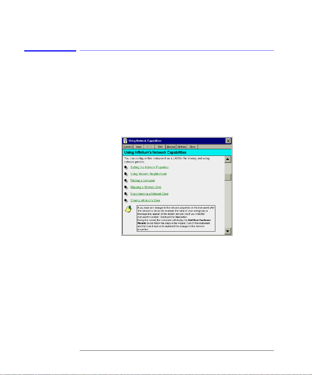
Step 9. Configure the instrument on a LAN
Y ou can configure this instrument on a LAN for file sharing and using network
printers. Contact your company’s network administrator to set up your instrument with the appropriate client, protocol, and configuration for your local
area network (LAN). The network setup is different for every company. If you
plan on sharing your instrument hard disk drive with other computers on your
LAN, you should have the network administrator enable file sharing as part of
the network setup. For more information on setting up a netwo rk drive, refer
to the built-in information system.
1-24
Page 31

Step 10. Avoid costly repairs
Setting Up the Infiniium DCA
Step 10. Avoid costly r epairs
CAUTION Electrical channel input circuits and the trigger input circuit can be damaged
by electrostatic discharge (ESD). Therefore, avoid applying static discharges
to the front-panel input connectors. P rior to connecting an y c oa xial cable to
the connectors, m o m entarily short th e ce nte r a nd outer conductors o f the
cable together. Avoid touching the front-panel input connectors without first
touching the frame of the instrument. Be sure that the instrument is properly
earth-grounded to prevent buildup of static charge. Wear a wrist-strap or heelstrap.
CAUTION Optical channel fiber-optic connectors are easily damaged when connected to
dirty or damaged cables and accessories. When you use improper cleaning and
handling techniques , y o u ri sk expensive instrument repairs, damaged cabl e s,
and compromised measureme nts . Before you connect any fiber-optic cable to
the Infiniium DCA, refer to “Cleaning Connections for Accurate
Measurements” on page 1-30.
1-25
Page 32

Setting Up the Infiniium DCA
Step 11. Perform a vertical calibration
Step 11. Perform a vertical calibration
A vertical (amplitude) calibration, also referred to as module calibration,
establishes c ali bra tio n fa ctor s for all ins tal le d mod ules . Th e ca libr at ion fac to rs
compensate for imper fecti ons in t he meas ure men t sys tem (f or e xamp le, va ria tions due to ambient temperature), resulting in the best instrument precision.
It is recommended that you perform this calibration routinely for best measurement accuracy.
The vertical calibration is recommended whenever the following occurs:
• Instrument power has been cycled
• A module has been removed and then reinserted
• A change in the tem perature of the mainframe excee d s 5°C compared to the
temperature of the last vertical (amplitude) calibration (
• The time since the last calibration has exceeded 10 hours
Refer to the Inf i n iium DCA’s built-in information sys te m for more information
concerning calibrations.
∆T > 5°C)
Warm-up time
Allow the instrument, with modules installed, to warm up for a period of at least one
hour before performing a vertical calibration. This ensures that the module reaches its
equilibrium temperature.
CAUTION Electrical channel input circuits and the trigger input circuit can be damaged
by electrostatic discharge (ESD). Therefore, avoid applying static discharges
to the front-panel input connectors. Prior to conne cti ng any coaxial cable to
the connectors, m o m entarily short th e ce nte r a nd outer conductors o f the
cable together. Avoid touching the front-panel input connectors without first
touching the frame of the instrument. Be sure that the instrument is properly
earth-grounded to prevent buildup of static charge. Wear a wrist-strap or heelstrap.
1-26
Page 33

Setting Up the Infiniium DCA
Step 11. Perform a vertical calibration
To perform a vertical calibrations
1 On the Calibrate menu, choo se All Calibrations.
The All Calibrations dialog box opens. This dialog box allows you to view the
calibration status of modules and initiate the calibration.
2 Touch the Vertical (Amplitude) tab.
The Vertical (Amplitude) tab opens and allows you to perform a vertical calibration on either the left or right module.
3 Touch the vertical calibration button (located at the bottom of
the tab) for the module you need to calibrate. This starts the
vertical calibration.
4 Remove all externa l devices and signals from th e mo du le.
The vertical calibration uses known signal levels in the instrument. Introducing an outside signal source wi ll interfere with the calibra tion factors and
decrease the accuracy of the calibration.
5 Touch Continue. A progress in di cator appears.
If the module has an electrical input channel, the following message will
appear instructi n g y o u to c onnect the front- pa ne l c a l ibration output to th e
input channel.
6 After the calibration completes, choose All Calibrations on the Calibration
menu.
1-27
Page 34

Setting Up the Infiniium DCA
Step 11. Perform a vertical calibration
7 The Vertical (Amplitude) tab shows the status of the calibration. The tab will
look similar to the fo llowing figure . Notice that the ta b indicates that the
“Current user vertical calibration is valid.”
1-28
Page 35

Setting Up the Infiniium DCA
Step 12. For more information
Step 12. For more information
T o learn more about this or any Agilent Technologies product, use your personal computer to visit our website at http://www.agilent.com. You cannot
access the Internet fro m the Infiniium DCA.
T o learn more about Fiber Optic Test Equipment, go to the Agilent Technologies home page shown above, and follow this path:
1 Click Products.
2 Click Test and Measureme nt.
3 Click Product Information, and then click Fiber Optic Test Equipment.
This path will take you to the Fiber Optic Test Equipment page. You can also
enter the URL for this page directly:
http://www.tm.agilent.com/tmo/Products/Englis h/FiberOptic TestEquipment.html
1-29
Page 36

Setting Up the Infiniium DCA
Cleaning Connections for Accurate Measurements
Cleaning Connections for Accurate
Measurements
Today, advances in measurement capabilities make connectors and connection techniques more important than ever. Damage to the connectors on calibration and verification devic es, te st ports, cables, and other devices can
degrade measurement accuracy and damage instruments. Replacing a damaged connector can cost thousands of dollars, not to mention lost time! This
expense can be avo ide d by obse rvi ng the s imple pr ecau tio ns p resen ted in t his
book. This book also contains a brief list of tips for caring for electrical connectors.
Choosing the Right Connector
A critical but often overlook ed factor in making a good lightwa v e measurement is the selection of the fiber-optic connector. The differences in connector types are mainly in the mechani c a l a ssembly that holds the ferrule in
position against another identical ferrule. Connectors also vary in the polish,
curve, and concentricity of the core within the cladd ing. Ma tin g one st yl e of
cable to another requires an adapter. Agilent T echnologies offers adapters for
most instruments to allow testing with many different cables. Figure 1-1 on
page 1-31 shows the basic componen ts of a ty pica l conn ectors.
The system tolerance for reflection and insertion loss must be known when
selecting a conne c t or from the wide variety of currently available connec tors.
Some items to consider when selecting a connector are:
• How much insertion loss can be allowed?
• Will the connector need to make multiple connections? Some connectors are
better than others, and some are very poor for making repeated connections.
• What is the refle ct ion tolerance? Can the syst em t ak e reflection degradat ion?
• Is an instrument-grade connector with a precision core alignment required?
• Is repeatability tolerance for reflection and loss important? Do your specifica-
1-30
Page 37

Setting Up the Infiniium DCA
Choosing the Right Connector
tions take repeatability uncertainty into account?
• Will a connector degrade the return loss too much, or will a fusion splice be required? For example, many DFB lasers cannot operate with reflections from
connectors. Often as much as 90 dB isol ati on is needed.
Figure 1-1. Basic components of a connector.
Over the last few ye a rs, the FC/PC style connector has em erged as the most
popular connector for fiber-optic applications. While not the highest performing connector, it represents a good compromise between performance, reliability, and cost. If properly maintained and cleaned, this connector can
withstand many repeated connections.
However, many instrument specifications require tighter tolerances than most
connectors, including the FC/PC style, can deli ve r. These instruments cannot
tolerate connectors with the large non-concentricities of the fiber common
with ceramic style ferrules. Wh en tighter alignm ent is required , Agilent
Technologies instruments typically use a connector such as the Diamond
HMS-10, which has concentric tolerances within a few tenths of a micron. Agilent Technologies then uses a special universal adapt e r, which allo ws other
cable types to mate with this precision connector. See Figure 1-2.
1-31
Page 38

Setting Up the Infiniium DCA
Choosing the Right Connector
Figure 1-2. Universal adapters to Diamond HMS-10.
The HMS-10 enca se s the fiber within a so ft nickel silver (C u/ Ni/Zn) center
which is surrounded by a tough tun gs ten carbide casing, as shown in
Figure 1-3.
Figure 1-3. Cross-section of the Diamond HMS-10 connector.
The nickel silver allows an active centering process that permits the glass fiber
to be moved to the desired position. This process first stakes the soft nickel
silver to fix the fiber in a near-center location, then uses a post-active staking
to shift the fiber into the desired position within 0.2
µm. This proces s, pl us th e
keyed axis, allows very precise core-to-core alignments. This connector is
found on most Agilent Technologies lightwave instruments.
The soft core, wh ile allowing precise cent ering, is also the chief li a bility of the
connector. The soft material is easily damaged. Care must be taken to minimize excessive scra tc h ing and wear. Wh ile minor wear is not a problem if the
1-32
Page 39

glass face is not af fected, scratch es or grit can cause the glass fiber to move
out of alig nment. Also , if unkeye d c onnect ors a re us ed, th e ni ckel silver can be
pushed onto the glass surface. Scratches, fiber movement, or glass contamination will caus e loss of s igna l and in creas ed re fl ect ion s, res u ltin g in p oor retu rn
loss.
Inspecting Connectors
Because fiber-optic connectors are susceptible to damage that is not immediately obvious to the naked eye, b ad m eas ure m ents can be made without the
user even being aware of a connector problem. Although microscopic examination and return loss measurements are the best way to ensure good connections, they are not always practical. An awareness of potential problems, along
with good cleaning practices, can ensure that optimum connector performance is maintained. With glass-to-gla ss interfaces, it is clear tha t any degradation of a ferrule or the end of the fiber, any stray particles, or finger oil can
have a significant effect on connector performance.
Figure 1-4 shows the end of a clean fiber-optic ca ble. The dark circle in the
center of the micrograph is the fiber’s 125
the light. The sur ro unding area is the soft nic k el-silver ferrule. Figure1-5
shows a dirty fiber end from neglect or perhaps improper cleaning. Material is
smeared and gr ou nd i nto t he end of t he f ib er cau si ng l igh t s ca tter in g an d po or
reflection. Not only is the precision polish lost, but this action can grind off the
glass face and destroy the connector.
Figure 1-6 shows phy s ic a l d amage to the glass fib e r end caused by either
repeated connec tions made without removing lo o se p a rticles or using
improper cleaning tools. When severe, the damage on one connector end can
be transferred to another good connector that comes in contact with it.
The cure for these problems is disciplined connector care as described in the
following lis t an d in “Cleaning Connecto rs” on page 1-36.
Use the following guidelines to achieve the best possible performance when
making measuremen ts on a fiber-o pt ic system:
Setting Up the Infiniium DCA
Inspecting Connectors
µm core and cladding which carries
• Never use metal or s h ar p objects to clean a connector and never sc rape the
connector.
• Avoid matching gel and oils.
1-33
Page 40

Setting Up the Infiniium DCA
Inspecting Co nnectors
Figure 1-4. Clean, problem-free fiber end and ferrule.
Figure 1-5. Dirty fiber end and ferrule from poor cleaning.
Figure 1-6. Damage from improper cleaning.
While these often work well on first insertion, they are great dirt magnets. The
oil or gel grabs and holds grit that is then ground into the end of the fiber.
Also, some early gels were designed for use with the FC, no n- c ontacting con-
1-34
Page 41

Setting Up the Infiniium DCA
Inspecting Connectors
nectors, using small glass spheres. When used with contacting connectors,
these glass balls can scratch and pit the fiber. If an index matching gel or oil
must be used, apply it to a freshly cleaned connector, make the measurement,
and then immediately clean it off. Never use a gel for longer-term connections
and never use it to improve a damaged connector. The gel can mask the extent
of damage and continued use of a damaged fib er can trans fer damage to the
instrument.
• When insertin g a fib er-optic cable into a connector, gently insert i t in as
straight a l ine as pos sible. Tip ping and inserting at an angle can scrape material
off the inside of the connector or even break the inside sleeve of connectors
made with ceramic material.
• When inserting a fiber-optic connector into a connector, make sure that the fiber end does not touch the ou ts ide of the mating connector or adapter.
• Avoid over tightening connections.
Unlike common electrical connections, tighter is not better. The purpose of
the connector is to bring two fiber ends together. Once they touch, tightening
only causes a great er f or c e to be applied to the delicate fi bers. With connec tors that have a convex fiber end, the end can be pushed off-axis resulting in
misalignmen t a nd e xc essive return loss. Many meas ure ments are actu a lly
improved by backing off the c o nnector pressure. Also, if a pi e c e o f grit does
happen to get by the cleaning procedure, the tighter connection is more likely
to damage the glass. Tighten the connectors jus t until the two fibers to uc h.
• Keep connectors covered when not in use.
• Use fusion splices on the more permanent critical nodes. Choose the best con-
nector possible. Replace connecting cables regularly. Frequen tly measure the
return loss of the connector to check for degradation, and clean every connector, every time.
All connectors should be treated like the high-quality lens of a good camera.
The weak link in instrument and system reliability is often the inappropriate
use and care of the connector. Because current connectors are so easy to use,
there tends to be re duced vigilance in conn ec t or care and cleaning. It takes
only one missed cle a ning for a piece of grit to permanently da m a g e the glass
and ruin the conne c to r.
Measuring insertion loss and return loss
Consistent measureme nts with your lightwave equipm ent are a good indication that you have good connection s. S ince return loss an d insertion loss are
key factors in determining optical connector performance they can be used to
determine connector degradation. A smooth, polished fiber end should pro-
1-35
Page 42

Setting Up the Infiniium DCA
Cleaning Connectors
duce a good return-loss measurement. The quality of the polish estab lis hes
the difference between the “PC” (p hysical contact) a nd the “Super PC” connectors. Most connectors today are physical contact which make glass-to-glass
connections, therefore it is critical that the area around the glass core be clean
and free of scratches. Although the major area of a connector, excluding the
glass, may show sc ratc hes and wear, if the glass has mainta ined its polishe d
smoothness, the connector can stil l provide a good low level ret urn loss connection.
If you test your cables and accessories for insertion loss and return loss upon
receipt, and retain the measured data for comparison, you will be able to tell in
the future if any degradation has occurred. Typical values are less than 0.5 dB
of loss, and sometimes as little as 0.1 dB of loss with high performance connectors. Return loss is a measure of reflection: the less reflection the better
(the larger the return loss, the smaller the reflection). The best physically
contacting connectors have retur n los se s better than 50 dB, although 30 to
40 dB is more common.
Visual inspection of fiber ends
Visual ins pe cti on o f fibe r en ds c an be hel pfu l. Con t amin at ion o r im perf ect ion s
on the cable end face can be detected as well as cracks or chips in the fiber
itself. Use a microscope (100X to 200X magni fi cation) to inspect the entire
end face for contam ina tion, raised me ta l , o r de nts in the metal as well as any
other imperfections. Inspect the fiber for cracks and chips. Visible imperfections not touching the fibe r cor e m ay not affect performance (unles s the
imperfections keep the fibers from contacting).
Cleaning Connectors
The procedures in this section provide the proper steps for cleaning fiberoptic cables and Agilent Technologies universal adapters. The initial cleaning,
using the alcohol as a solvent, gently removes any grit and oil. If a caked-on
layer of material is still present, (this can happen if the beryllium-copper sides
of the ferrule retainer get scraped and deposited on the end of the fiber during
insertion of the cable), a second cleaning should be performed. It is not
uncommon for a cable or connector to re q uire more than one cleaning.
CAUTION Agilent Technologies strongly recommends that index matching compounds
not be applied to their instruments and accessories. Some compounds, such as
gels, may be difficult to remove and can contain damaging particulates. If you
think the use of such compounds is necessary, refer to the compound
manufacturer for information on application and clea ni ng procedures.
1-36
Page 43

Setting Up the Infiniium DCA
Table 1-10. Cleaning Accessories
Item Agilent Part Number
Isopropyl alcohol 8500-5344
Cotton swabs 8520-0023
Small foam swabs 9300-1223
Compressed dust remover (non-resi due) 8500-5262
Table 1-11. Dust Caps Provided with Lightwave Instruments
Item Agilent Part Number
Laser shutter cap 08145-64521
FC/PC dust cap 08154-44102
Biconic dust cap 08154-44105
DIN dust cap 5040-9364
HMS10/dust cap 5040-9361
ST dust cap 5040-93 66
Cleaning Connectors
To clean a non-lensed connector
CAUTION Do not use any t y p e of foam swab to clean o ptical fiber ends. Fo a m swabs can
leave filmy deposits on fiber e nds that can degrade performance.
1 Apply pure isopropyl alcoh o l to a cle a n li nt-free cotton swab or lens pape r.
Cotton swabs can be used as long as no cotton fibers remain on the fiber end
after cleaning.
2 Clean the ferrules and othe r parts of the connector while avoi di ng the end of
the fiber.
3 Apply isopropyl alcohol to a new clean lint-free cotton swab or lens paper.
4 Clean the fiber end with the swab or lens paper.
Do not scrub durin g this initial cle a ni ng because grit c a n be caught in the
swab and become a gouging element.
5 Immediately dry the fiber end with a clean, dry, lint-free cotton swab or lens
paper.
6 Blow across the connector end face from a distance of 6 to 8 inches using
1-37
Page 44

Setting Up the Infiniium DCA
Cleaning Connectors
filtered, dry, compressed air. Aim the compressed air at a shallow angle to the
fiber end face.
Nitrogen gas or com pressed dust rem o v e r c a n a lso be used.
CAUTION Do not shake, tip, or invert compressed air canisters, because this releases
particles in the can into the air. Refer to instructions provided on the
compressed air canister.
7 As soon as the conn ec t or is dry, connect or cover it fo r later use.
If the performance, after the initial cleaning, seems poor try cleaning the connector again. Often a second cleaning will restore proper performance. The
second cleaning should be more arduous with a scrubbing action.
To clean an adapter
The fiber-optic input and output connectors on ma ny Agilent Technologies
instruments employ a universal adapter such as those shown in the following
picture. These adapters allow you to connect the instrument to different types
of fiber-optic cables.
Figure 1-7. Universal adapters.
1 Apply isopropyl alcohol to a clean foam swab.
Cotton swabs can be used as long as no cotton fibers remain after cleaning. The
foam swabs listed i n t hi s sec t ion’s introduction ar e sma ll enough to fit into
adapters.
Although foam sw abs can leave film y deposits, th ese deposits a re very thin, and
the risk of other conta m ination buildup o n the inside of adapters greatly outweighs the risk of contamination by foam swabs.
2 Clean the adapter with the foam swab.
3 Dry the inside of the adapter with a clean, dry, foam swab.
4 Blow through the adapter using filtered, dry, compressed air.
Nitrogen gas or compressed dust remover can also be used. Do not shake, tip,
or invert compressed air canisters, because this releases particles in the can
into the air. Refer to instructions provided on the compressed air canister.
1-38
Page 45

Setting Up the Infiniium DCA
Returning the Instrument for Service
Returning the Instrument for Service
The instructions in this section show you how to properly package the instrument for return to a Ag ilent Technologies service off ic e . For a list of offices ,
refer to “Agilent Technologies Serv ic e Offices” on page 1-42.
If the instrument is sti ll under warranty or is covered by an Ag il e n t m aintenance contract, it will be repaired under the terms of the warranty or contract
(the warranty is at the front of this manua l ) . If the instrument is no longer
under warranty o r is not covered by an Agilent mai nt enance plan, Agilent wi ll
notify you of th e c os t of the repair after examining the unit.
When an instrument is returned to a Agilent service office for servicing, it
must be adequatel y packaged and hav e a c omplete description of the failure
symptoms attached.
When describing the failure, please be as specific as possible about the nature
of the problem. Include copies of additional failure informat ion (such as the
instrument failure settings, data related to instrument failure, and error messages) along with the original cal data disks and the instrument being
returned.
Please notify the service office before returning your instrument for service.
Any special arrangements for the instrum ent can be discussed at this time.
This will help the Agilent service office repair and return your instrument as
quickly as possible.
Preparing the instrument for shipping
1 Write a complete description of the failure and attach it to the instrument.
Include any specific performance details related to the problem. The following
1-39
Page 46

Setting Up the Infiniium DCA
Preparing the instrument for shipping
information should be returned with the instrument.
• Type of service requ ired.
• Date instrument was returned for repair.
• Description of the pr oblem:
• Whether problem is constant or intermittent.
• Whether instrument is temperature-sensitive.
• Whether instru ment is vibration-sens itive.
• Instrument settings required to reproduce the problem.
• Performance data.
• Company name and return addr ess.
• Name and phone number of techn ical contact person.
• Model number of returned instrument.
• Full serial number of returned instrument.
• List of any accessories returned with instrument.
• The original ca l da ta disks.
2 Cover all front or rear-panel connectors that were originally covered when you
first received the instrument.
CAUTION Cover electrical connectors to protect sensitive components from electrostatic
damage. Cover opti cal connectors to protect them from da mage due to physical
contact or dust.
CAUTION Instrument damage can result from using packaging materials other than the
original materials. Never use styrene pellets as packaging material. They do not
adequately cus hion the instrumen t o r prevent it from shifting in the carton.
They may also cause instrument damage by generating static electricity.
3 Pack the instrument in the original shipping containers. Original materials are
available throu gh any Agilent office. Or, use the followin g gu idelines:
• Wrap the inst rument i n antist atic pla stic t o reduce the pos sibilit y of dama ge
caused by electrostatic discharge.
• For instruments weighing less than 54 kg (120 lb), use a double-walled, corrugated cardboard carton of 159 kg (350 lb) test strength.
• The carton must be large enough to allow approximately 7 cm (3 inches) on
all sides of the in strument for pac king material, and strong enou gh to accommodate the weight of the instrument.
• Surround the equipment with approximately 7 cm (3 inches) of packing material, to protect the instrument and prevent it from moving in the carton. If
packing foam is not available, the best alternative is S.D-240 Air Cap™ from
1-40
Page 47

Setting Up the Infiniium DCA
Preparing the inst rument for shipping
Sealed Air Corporation (Commerce, Califor nia 900 01). Air Cap look s like a
plastic sheet filled with air bubbles. Use the pink (antistatic) Air Cap™ to
reduce static electricity. Wrapping the instrument several times in this material will protect the instrument and prevent it from moving in the carton.
4 Seal the carton with strong nylon adhesive tape.
5 Mark the carton “FRAGILE, HANDLE WITH CARE”.
6 Retain copies of all shipping papers.
1-41
Page 48

Setting Up the Infiniium DCA
Agilent Technologies Servic e Offices
Agilent Technologies Service Offices
Before returni ng an ins tr ument for service, call the Agilent Technologies
Instrument Support Center at (800) 403-0801, visit the Test and Measurement
Web Sites by Country page at http://www.tm.agilent.com/tmo/country/English/
index.html, or call o ne of the num ber s listed below.
Agilent Technologies Service Numbers
Austria 01/25125-7171
Belgium 32-2-778.37.71
Brazil (11) 7297-8600
China 86 10 6261 3819
Denmark 45 99 12 88
Finland 358-10-855-2360
France 01.69.82.66.66
Germany 0180/524-6330
India 080-34 35788
Italy +39 02 9212 2701
Ireland 01 615 8222
Japan (81)-426-56-7832
Korea 82/2-3770-0419
Mexico (5) 258-4826
Netherlands 020-547 6463
Norway 22 73 57 59
Russia +7-095-797-3930
Spain (34/91) 631 1213
Sweden 08-5064 8700
Switzerland (01) 735 7200
United Kingdom 01 344 366666
United States and Canada (800) 403-0801
1-42
Page 49

2
Working in Comfor t
Page 50

Working in Comfort
Working in Comfort
Working in Comfort
T o optimize your comfort and productivity, it is important that you set up your
work area corre ctly and use your Agile nt product proper ly. With that in mind,
we have developed some setu p and use recommendations for you to follow
based on established erg o nomic principles.
Improper and prolonged use of keyboards and input devices are among those
tasks that have been associated wi th re pe titive strain injury (RSI) to soft tissues in the hands and arms. If you experience discomfort or pain while using
your Agilent Technologies product, discontinue use immediately and cons ult
your physician a s soon as possible.
Please study the recommendations offered here in this chapter. You may also
wish to consult your emplo ye r’s human resources department or other relevant departments for guidance specific to your company.
About Repetitive Strain Injury
Because your comfort and safety are our primary concern, we strongly recommend that you use the infiniium DCA in accordance with established ergonomic principles and recommendations. Scientific literatu re suggests that
there may be a relati onship between injury to soft tissue s - especially in the
hands and arms - and prolonged improper use of keyboards or other eq uipment requiring repeated motio ns of the hands and fo rearms. This lit erature
also suggests th a t there are many other risk factor tha t may increase th e
chance of such injury, commonly called Repetitive Strain Injury.
What is RSI? Repetitive Strain Injury (RSI—also known as cumulative trauma disorder or
repetitive m otion inju ry) is a type of injury wh ere soft ti ssues in the body, such
as muscles, nerves, or tendons, become irri t a ted or inflamed. RSI has been a
reported problem for those who perform repetitive tasks such as assembly line
work, meatpacking, sewing, playing musical instruments, and computer work.
2-2
Page 51

Working in Comfort
Mice and Other Input Devices
RSI has also been observed in those who frequently engage in activities such
as carpentry, knitting, housework, gardening, tennis, windsurfing and lifting
children.
What causes RSI? The specific causes of RSI have not been established. Nevertheless, the inci-
dence of RSI has been associated with a variety of risk factors, including:
• Too many uninterrupted repetitions of an activity or motion.
• Performing an a ct i v ity in an awkward or unnatural posture.
• Maintaining a sta t ic position for prolonged periods.
• Failing to take frequent short breaks.
• Other environmental and social factors.
In addition, there ha v e been reports associating the o c c urrence of RSI with
the use of keyboards, mice, and other input devices. Also, certain medical conditions, such as rh eumatoid arthritis, obesity and diabetes, may pr ed ispose
people to this type of injury.
What if I
experience
discomfort?
If you are experiencing any discomfort, seek profess ion al medical advi ce
immediately. Typically, the earlier a problem is diagnosed and treated, the easier it is to resolve.
Mice and Other Input Devices
Various aspects of using mice and other input devices may increase your risk
of discomfort or injury. Observing the following recommendations may reduce
that risk.
• Try to keep your hand, wrist, and forearm in a neutral position while using your
mouse or other input devi ce.
• If you use your thumb to rotate the ball on a trackball or spaceball, keep it in a
relaxed, natural shape, and maintain a neutral posture in your hand, wrist, and
forearm.
• Hold the mouse gently by draping your fingers over it. Keep your hand relaxed
and fingers loose. Do not grip the mouse tightly.
• It takes very little pressure or force from your fingers to activate the buttons or
scroll wheel on your mouse, scrolling mouse, trackball, or other input device.
Using too much force can pla ce unnecessa ry stress on th e tendons and muscles
2-3
Page 52

Working in Comfort
Mice and Other Input Devices
in your hands, wris ts, and forearms.
• If you are using a scrolling mouse, be sure to keep your fingers and hand in a
relaxed, neutral position when activating the scroll wheel. Also, this type of
mouse features software that can minimize the number of mouse movements
or button clicks.
• When using a mouse, trackball, or other input device, position it as close to the
keyboard as possible, and keep it at the same level as you do not have to stretch
while using it.
• Use a good quality mouse pad to enable the mouse to work most effectively and
reduce unnecessary hand and wrist movements.
• Be sure to keep your mouse and trackball clean. Regular removal of accumulated dust and dirt helps en sure proper tracking and redu ce s unnecessary hand
and wrist motions.
2-4
Page 53

3
Introduction 3-2
Oscilloscope Mode 3-8
Eye/Mask Mode 3-7
TDR/TDT Mode 3-9
Using Plug-in Modules 3-10
Using the Touch Scr een 3-12
Using the Quick Measure Feature 3-14
If the Display Goes Blank 3-15
Hiding and Moving Dialog Boxes 3-16
Menus 3-17
Using the Infiniium DCA
Page 54

Using the Inf iniium DCA
Introduction
Introduction
The Infiniium DCA is designed to measure a variety of high speed digital communication waveforms. Y ou can op er a te it in any of the following three instrument modes:
• Eye/Mask Mode (100 Mb/s to 10 Gb/s) for eye diagram analysis and standards
testing (for example, SO N ET/SDH, Gigabit Ethernet, and Fiber Channel).
• TDR/TDT Mode for time domain reflectometry measurements
• Oscilloscope Mode (DC to 20 GHz or 50 GHz)
3-2
Page 55

Using the Infiniiu m DCA
Introduction
Use the touch screen
You can explore the i nstrument’s menus and change its settings by touching
the display. Notice that the measurem ent toolbar ch a nges depending on the
selected instrument mode. Touch the channel, time and delay, and trigger
level buttons located at the bottom of the display to change the horizontal and
vertical scales. Or, you can change these settings using front-panel knobs and
buttons.
3-3
Page 56

Using the Inf iniium DCA
Introduction
Refer to the built-in information system
T o learn how to use your Infiniium DCA and to locate information on specifications (including plug-in modules), instrument features, and measurement
configuration refer to Chapter 4, “Using the Built-In Information System” in
this book.
You must provide a trigger input signal
Because high-speed oscilloscopes are not capable of triggering directly on a
test signal, you must first connect an external timing reference signal to the
front-panel trigger input connector. This input allows the Infiniium DCA to
synchonize to the input sig nal . You can select free-run trigge ring when an
external trigger is unavailable. However, you will only be able to view the
waveform for amplitude information only without any timing information. This
is an easy way to examine the amplitude of a signal.
3-4
Page 57

Using the Infiniiu m DCA
Introduction
Front-panel features
The following fi gure shows the input connectors, c ontrols, power switch, and
other front-panel features available on the Infiniium DCA.
3-5
Page 58

Using the Inf iniium DCA
Introduction
Rear-panel features
3-6
Page 59

Using the Infiniiu m DCA
Eye/Mask Mode
Eye/Mask Mode
The Eye/Mask mode allows you to perform eye diagram meas ur ements and
eye mask tests. The eye diagram is typically produced by triggering the instrument with a synchronous clock signa l.
Eye/Mask mode measurements only
work when an eye diagram, and not a
pulse, is present on the screen. Measurements made on a puls e wave form
while in Eye/Mask mode will fail.
Once you are in Eye/Mask mode, press the Autoscale button. This ensures
that an optimum eye diagr a m is dis played on the graticule. An optimu m eye
diagram consists of a full display of the eye in addition to portions of the waveform preceding a nd following the eye .
When you select th e E ye/Mask mode, the
measurement toolbars shown here appear.
These measurement toolbar s include measurements such a s ri se time, fall time, ji tter,
and extinction ratio, as well as the mask test
start and stop controls.
Eye measurement and mask test results
appear below the display graticule. A maximum of four eye measurement test results
are displayed and include any failures or
instrument messages that may occur.
To learn more about the Eye/ Mask mode,
consult the instrument’s built-i n informa tion
system.
3-7
Page 60
Using the Inf iniium DCA
Oscilloscope Mode
Oscilloscope Mode
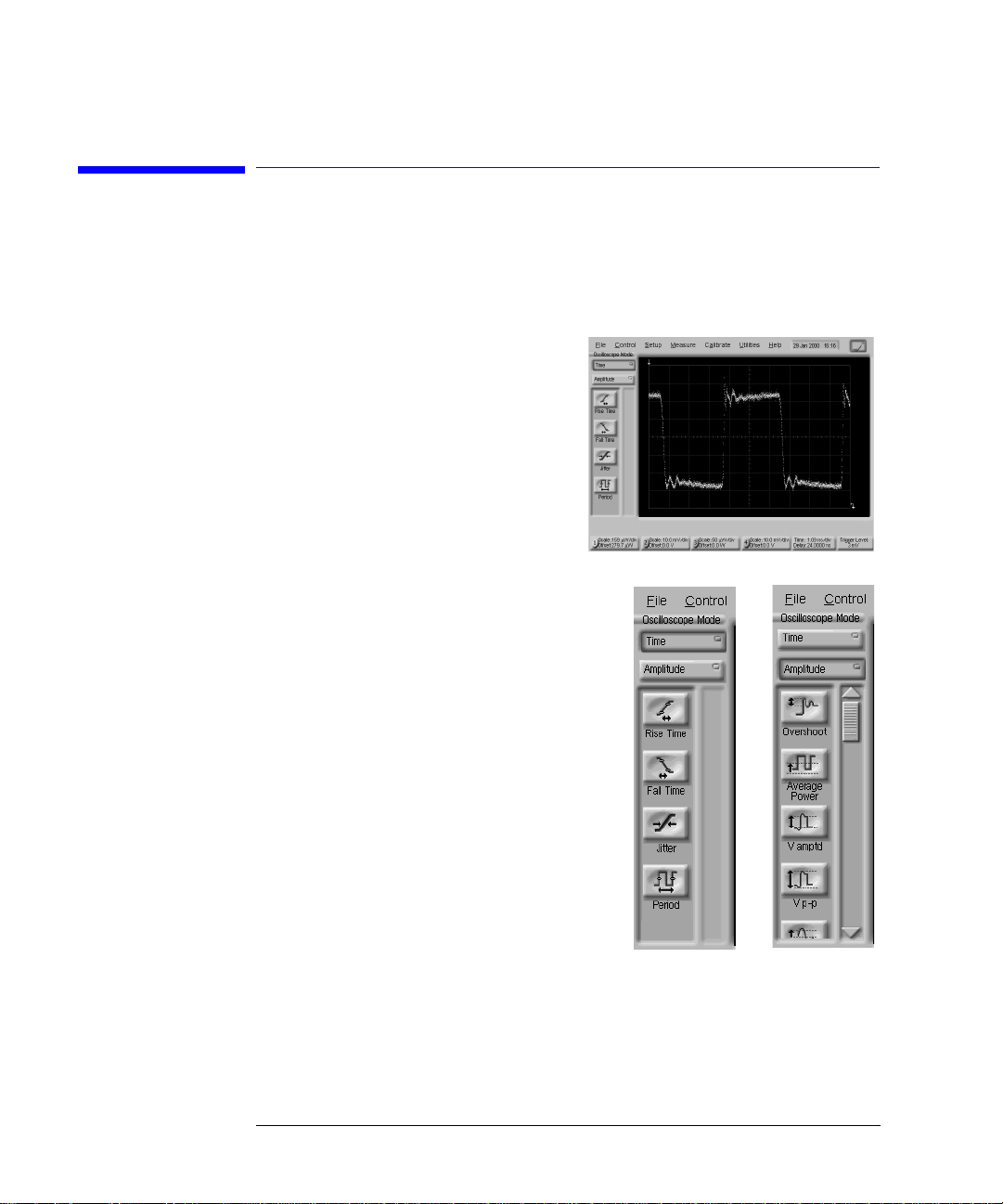
Use the Oscilloscope mode for pulse
type waveforms that are triggered by
an external sig na l. Oscillosco pe mode
measurements only work when a single
valued waveform, and not an eye diagram, is present on the screen.
When you select the Oscilloscope
mode, the measurement toolbars sho w n
here appear. These measurement toolbars
include measurements such as rise time, fall
time, overshoot, and Vp-p. All measurements, with the exc eption of jitter, can be
performed on any of the following sources:
channels, waveform memories, and math
functions. One of the above sources must be
turned on in order to perform an oscilloscope measurement.
If more than one source is turned on and
you initiate a measurement, the Enter Measurement Info dialog box opens. This dialog
box allows you to select the source you want
to use for the measure m ent.
Measurement results appear below the display graticule. A maximum of four pulse
measurement t est re sult s a re di splay ed an d in clu de any fa ilur es or ins tru ment
messages that may occur.
To learn more about the Oscilloscope mode, consult the ins trument’s built-in
information system.
3-8
Page 61
TDR/TDT Mode
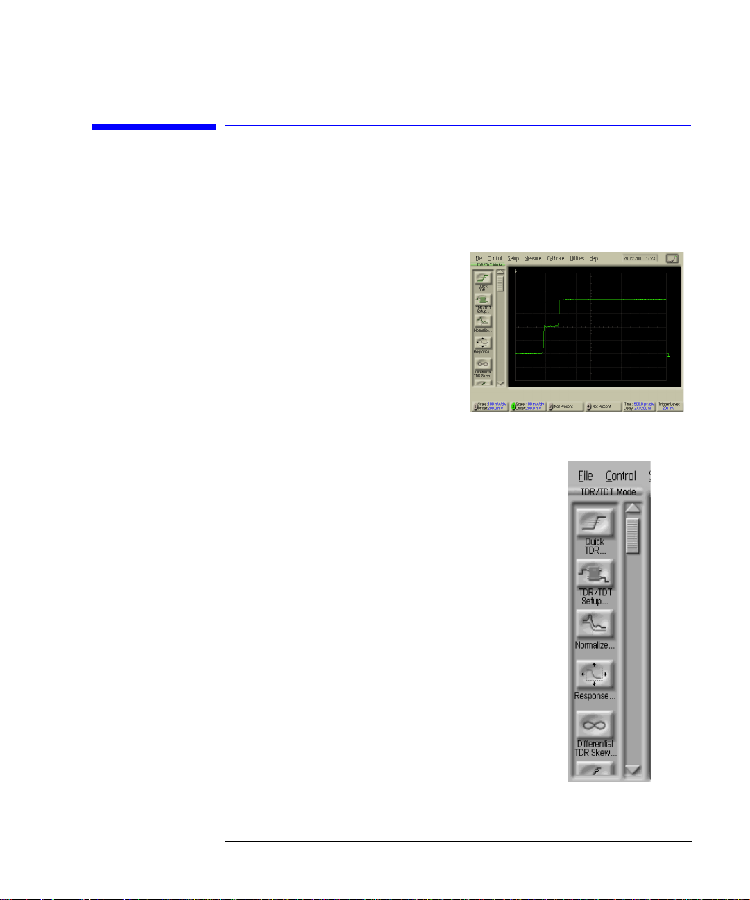
The TDR/TDT mode allows you use
time domain reflectometry (TDR) to
verify the proper functioning of the
physical components of your devi ce
under test using a time-delayed electrical pulse. You can also use time domain
transmission (TDT) to measure both
the attenuation and propagation de lay
of your device under test.
TDR/TDT mode mea su rements when
using a single-ended or differential
TDR/TDT 5475 x series plug-in modu le.
When you select the TDR/TDT mode, the measurement toolbar shown here appears. This measurement
toolbar includes measurements such as Quick TDR,
normalization, rise time, and fall time. Quick TDR
allows you to view an immediate display of the char a c teristics of your device under test. You can also use this
toolbar to perform tasks such as setting up the stimulus and destination for your measurement.
You can use markers to to verify the impedance, voltage, and percent of reflection of a selected point on the
waveform trace. TDR/TDT markers are initi ate d by
turning on the X-axis marker(s) only. The Y-axis
marker(s) will then track the waveform at the position
determined by the X- axis marker. You ca n view the
position of the marker values in the marker values tab
located below the display graticule.
To learn more about the TDR/TDT mode, consult the
instrument’s built-in inform a tion system.
Using the Infiniiu m DCA
TDR/TDT Mode
3-9
Page 62

Using the Inf iniium DCA
Using Plug-in Modules
Using Plug-in Modules
The Infiniium DCA holds up to two plug-in modules which can provide up to
four measurement channels. Each input channel has its own vertical controls.
The amplitude scale knob adjusts the amplitude scale used for the input channel. Use the amplitude offset knob to position the displayed signal. You can
also set the amplitude scale and offset to specific values by touching of channel buttons shown to at the bottom of the display.
To install a module
• Slide the module into an available slot and finger tighten the two front-panel
locking scre w s.
3-10
Page 63

Using the Infiniiu m DCA
Using Plug-in Modules
You can use 8348x and 5475x series plug-in modules
In addition to a complete line of modules designed specifically for this instrument, modules designed for use with H P/ Agil e nt 83480A and 54750A mainframes can also be installed into the Infiniium DCA. The 8348x and 5475x
series plug-in modules are equipped with a trigger input on the individual
module front panels. Repeatedly press the Infiniium DCA’s front-pane l Trigger
Source button until the label for the de si red trigger sourc e is lit.
CAUTION Electrical channel input circuits and the trigger input circuit can be damaged
by electrostatic discharge (ESD). Avoid applying static discharges to the frontpanel input connectors. Prior to connecting any coaxial cable to the
connectors, momentarily short the center and outer conductors of the cable
together. Avoid touching th e front-panel input connect ors without first
touching the frame of the instrument. Be sure that the instrument is properly
earth-grounded to prevent buildup of static charge. Wear a wrist-strap or heelstrap.
CAUTION Optical channel fiber-optic connectors are easily damaged when connected to
dirty or damaged cables and accessories. When you use improper cleaning and
handling techniques , y o u ri sk expensive instrument repairs, damaged cabl e s,
and compromised measureme nts . Before you connect any fiber-optic cable to
the digital communications analyzer, refer to “Cleaning Connections for
Accurate Measurements” on page 1-30.
3-11
Page 64

Using the Inf iniium DCA
Using the Touch Screen
Using the Touch Screen
There may be times when you would lik e to di sa b le the touch scree n feature.
For example, when pointing out a measurement result without initiating a
change to the instrument. You can temporarily disab le the touch scree n fo r
this purpose.
A touch screen configuration utility can be used to ensure that the touch
screen is both aligned and orientated with the display. It also allows you to
adjust the touc h s cre en s pe ed t o s imula te a d oub le- clic k and t o t urn the tou ch
screen sound on or off.
To temporarily di sable the touch screen
• Touch the disable button which is located at the top of the display. Touch the
button a second time to reenable the to uch screen.
To configure the touch screen
1 On the Utilities menu, select Touch Screen Config.
The touch screen configuration utility is displayed.
3-12
Page 65

Using the Infiniiu m DCA
Using the Touch Screen
2 Touch Calibration and follow th e di spl a y ed instructions.
3 After returning to the C o nfiguration Utili ties dialog box show n a bove, touch
Properties . Ma k e any desired changes.
3-13
Page 66

Using the Inf iniium DCA
Using the Quick Measure Feature
Using the Quick Measure Feature
Press the user-definable Qui c k M e a su re button and the Infiniium DCA automatically performs four m e asurements on a displayed si gnal. You can configure Quick Measure to include any four measurements located on the
measurement tool bar. Quick Measure has a defaul t se t of me as urements for
each instrument mode. For example, in Oscilloscope mode the default measurements are: peak-to-peak voltage, period, frequency, and rise time. In Eye/
Mask mode you can also configur e Quick Measure to perform a mask tes t.
To configure Quick Measure
• On the Measure menu, sel ect Qui c k Measure Config.
3-14
Page 67

Using the Infiniiu m DCA
If the Display Go es Blank
If the Display Goes Blank
The display automatically turns off if the Infiniium DCA is powered over an
eight hour pe rio d wit hou t being u se d. Th e pu rpo se of thi s fe atu r e is to ext end
the life of the display. Y ou can adjust the amount of time that must elapse
before the scr een is t urn ed o ff by t he b ackl ight sa ver utili ty (for examp l e, 2 , 4,
6, or 8 hours). This feature is especially useful if you are using remote measurements or leaving the instrument unattended for long periods of time.
Although not recommended, you can disable this control so that the backlight
is never turned off during inactivity.
To reactivate the display
• Touch the display screen
• Move the mouse (if applicable)
• Touch any button on the instrument front panel
• Turn any knob on the instrument front panel
To configure the backlight saver
1 Choose Display from the Setup menu.
2 Touch or cli ck the Enabled chec k box to enable or d isable the backli ght control.
3-15
Page 68

Using the Inf iniium DCA
Hiding and Moving Di alog Boxes
Hiding and Moving Dialog Boxes
Sometimes, dial og boxes may cover portions of a di sp la yed signal and graticule that you wish to see. Y ou can either move the dialog box or make it transparent.
To move a dialog box
• Touch the top of the dialog box, and drag your finger across of display to move
the dialog box to a more convenient location.
To make a dialog box transparent
1 Select Dialog Boxes from the Se tup menu.
2 Touch or click Opaque or Transparent.
3-16
Page 69

The File menu
Using the Infiniiu m DCA
Menus
Menus
The menu includes the File, Control, Setup, Measure, Calibrate, Utilities, and
Help drop-down menus. For detailed information on each of these menus, see
the built-in information system.
3-17
Page 70

The Control menu
The Setup menu
Using the Inf iniium DCA
Menus
3-18
Page 71

The Measure
menu
Using the Infiniiu m DCA
Menus
The Calibrate
menu
3-19
Page 72

The Utilities menu
The Help menu
Using the Inf iniium DCA
Menus
3-20
Page 73

4
The Contents Topic 4-3
Using Setup Guides 4-4
Getting Help While Changing Instrument Settings 4-6
Learning About Measurem ents Results 4-7
Hiding the Built-in Information System 4-8
Printing the Content s of a Top ic 4-9
Selecting the Built-in Information System Language 4-10
Using the Built-In Information System
Page 74

Using the Built-In Information System
Using the Built-In Information System
Using the Built-In Information System
Where is the operating manual for your infiniium DCA? It is built into your
instrument! To access the built-in information system, simply touch Contents
on the Help menu. This w i ll display the contents topic that is shown in th e fi gure on the following page. In this chapter, you’ll learn features that are unique
to the Infiniium DCA’s built-in informa ti on system as well as tips that wil l
make the system more useful to you.
Navigating through the system should be familiar to you because it is similar to
other W indows applications. You can, of course, navigate through the help by
either using the touch screen capability or the mouse.
4-2
Page 75

Using the Built-In Info rmation System
The Contents Topic
The Contents Topic
The following fi gure shows the contents for the built-in information system.
This is the starting point for learning how to use your Infiniium DCA. From
this location, you can also access information such as instrument specifications and the algorithms used in the measurements.
In addition to the 10 topics presented in the contents, be sure to use the index
buttons located along the bottom. These can be very helpful in locating a topic
of interest.
4-3
Page 76
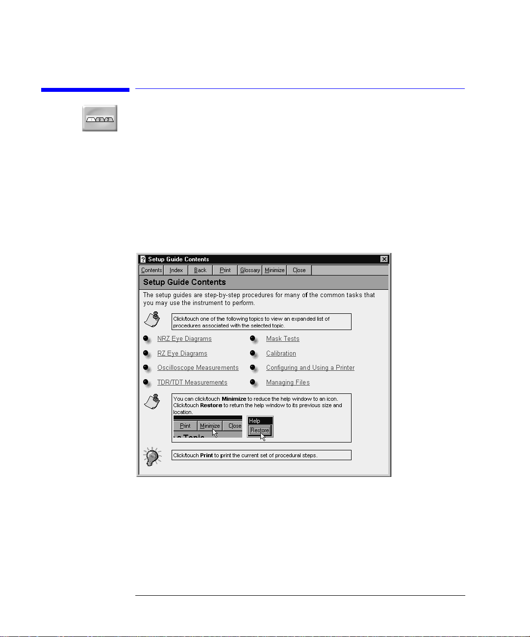
Using the Built-In Information System
Using Setup Guides
Using Setup Guides
The setup guides giv e yo u step-by-step procedures fo r many configuration
and measurement tasks . To find the setup guides, touc h the Setup Guide button in the contents. This brings up the Setup Guide Contents shown in the following figure. From this topic you can access a variety of step-by-step
procedures.
The following fi gure shows an exam ple of a setup guide. Notice that it shows
several tabs including the Overview tab. Simply follow the steps shown, and
then touch the next tab to pr oceed further.
4-4
Page 77

Using the Built-In Info rmation System
Using Setup Guides
Viewing the screen to perform the steps
Sometimes, the setup guide may cover portions of the display that you wish to
see. Use the follow ing techniques to view the display:
• Touch the top of the setup guide, and drag your finger across of display to move
the setup guide to a more convenient location.
• Temporarily hi de the informa tion system. Refer to “Hiding the Built-in Informa-
tion System” on page 4-8.
• Print the instructio ns if you have a printer c o nnected to the instrum ent.
4-5
Page 78
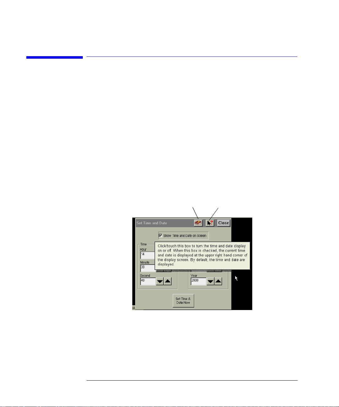
Using the Built-In Information System
Getting Help While Changing Instrument Settings
Getting Help While Changing Instrument
Settings
Help is available directly from dialog boxes in the graphical user interface.
• To see overview information in an open dialog box, touch the Book icon. A topic
window opens and describes the dialog box and its controls.
• To get informatio n on a specific item in the dialog box, to uch the What’s this?
icon. Then touch the desired control on the dialog box. A window appears with
a descriptio n o f th e selected control, as sho w n in the following figure.
Book icon
What’s this? icon
4-6
Page 79

Using the Built-In Info rmation System
Learning About Measurements Results
Learning About Measurements Results
After a measurement is performed, the displays shows the Measure tab which
includes the measurement results . The fastest way to ge t help on measurement configuration or algorithms is to touch the Setup & Info button. The following figure shows the location of this button.
4-7
Page 80

Using the Built-In Information System
Hiding the Built-in Information System
Hiding the Built-in Information System
When using the b uilt-in information system, yo u c a n temporarily hide it so
that you can see the entire display. Then, you can re-display the built-i n information system with the same topic still showing.
• To hide the built-in information system, touch the Minimize button located at
the top of the built-in information system.
• To re-display the built-in information system, touch the Restore button that is
shown on the display.
4-8
Page 81

Using the Built-In Info rmation System
Printing the Contents of a Topic
Printing the Contents of a Topic
Y ou can print the entire contents of a help topic or a pop-up window.
1 Connect a printer and a mouse pointing device to the Infiniium DCA.
2 Place the pointer over the topic, and click the right button. Then click on Print
Topic.
4-9
Page 82
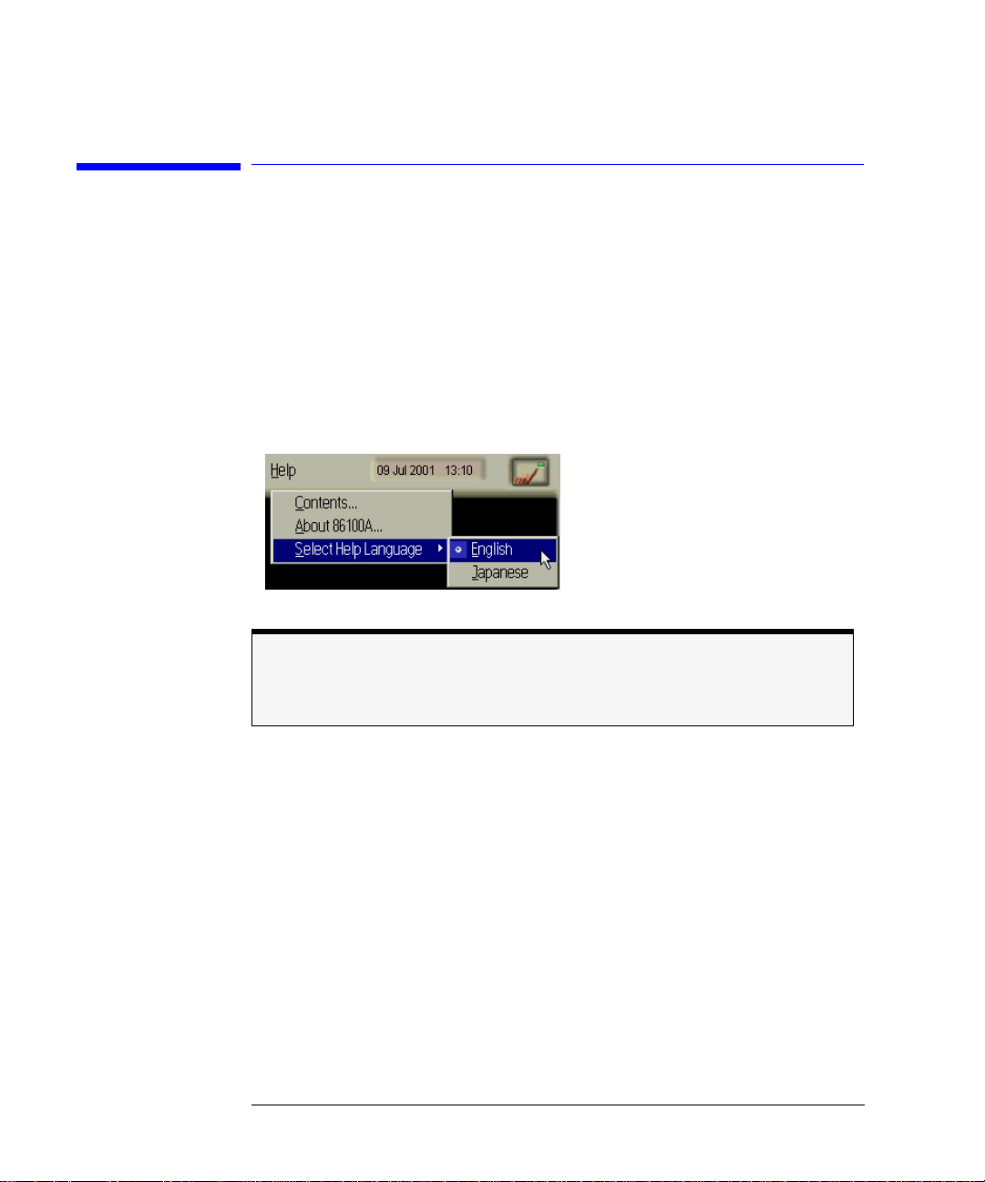
Using the Built-In Information System
Selecting the Built-in Information System Language
Selecting the Built-in Information System
Language
Help is available in more than one language. On the Help menu, touch Select
Help Language, and then touch the language you want to view. You can only
one version of help at a time.
Help Version
Refer to the English version of help to view the most current information about instrument features and specifications.
4-10
Page 83

5
Regulatory Informatio n
Page 84

Regulatory Information
Regulatory Information
Regulatory Information
Notice for Germany: Noise Declaration
Acoustic Noise Emission Geraeuschemission
LpA < 70 dB Lp A < 70 dB
Operator position am Arbeitsplatz
Normal position normaler Betrieb
per ISO 7779 nach DIN 45635 t.19
Notice for Canada: Complianc e with Can adi a n EMC Re qu ir em en ts
This ISM device complies with Canadian ICES-001.
Cet appareil ISM est conforme a la norme NMB du Canada.
5-2
Page 85

Regulatory Information
Regulatory Information
5-3
Page 86

Regulatory Information
Regulatory Information
5-4
Page 87

Index
Numerics
12 GHz trigger bandwidth, 1–4
5475x series plug-in modules, 3–11
8348x series plug-in modules, 3–11
A
accessories
connecting, 1–8
adapters
APC 3.5 (f-f), 1–5
SMA (f-f), 1–5
Add Printer Wizard, 1–16
Agilent offices, 1–41
Agilent website, 1–28
algorithms, 4–7
amplitude calibration, 1–25
amplitude offset, 3–10
amplitude scale, 3–10
Applications menu, 3–18
Autoscale button, 3–7
B
Beep on Touch setting, 1–22
blank screen, 3–15
Book icon, 4–6
built-in information system, 3–4, 4–2
temporarily hiding, 4–8
C
Calibrate TouchSurround, 1–21
calibration
amplitude, 1–25
vertical, 1–25
calibration certificate, 1–4
care of fiber optics, 1–24, 3–11
cleaning, iv
adapters, 1–37
fiber-optic connections, 1–29, 1–36
non-lensed connectors, 1–36
clock signal, 3–7
compressed dust remover, 1–36
connecting
accessories, 1–8
printer, 1–9
connector
care, 1–29
Contents topic, 4–2
contents topic, 4–3
cotton swabs, 1–36
D
Default Setup button, 1–22
dialog box
making transparent, 3–16
moving, 3–16
dialog boxes, 4–6
dimensions, 1–10
Display Area Configuration, 1–22
double touch, 1–22
Double Touch Speed, 1–22
Drag and Drop setting, 1–22
dust caps, 1–36
E
electrical channel input circuits, 1–25
electrostatic disch a rg e, 1–25
EMC requirements, 5–2
Eye/Mask Mode, 3–2, 3–7
F
fiber optics
care of, 1–24, 3–11
cleaning connections, 1–29
connectors, covering, 1–39
fiber-optic adapters, 1–6
File menu, 3–17
file sharing, 1–23
foam swabs, 1–36
front panel
power switch, 1–24
H
help, 4–2
help language, selecting, 4–10
help topic, printing, 4–9
I
input
Index-1
Page 88

Index
connector, 1–29
instrument
checking the shipment, 1–3
positioning, 1–8
powering up, 1–24
returning for service, 1–38
instrument modes, 3–2
isopropyl alcohol, 1–36
K
keyboard, 1–4, 1–8
L
LAN, 1–23
language version, 4–10
line cords, 1–12
line power
requirements, 1–13
M
Measure menu, 3–18
measurement channels, 3–10
measurement results, 4–7
measurement to olb ar , 3–3
measurement to olb ar s , 3–7, 3–8, 3–9
menu
bar, 3–17
menus, 3–17
Minimize button, 4–8
module, installing, 3–10
modules, installing, 1–7
mouse, 1–4, 1–8
N
network printers, 1–23
network setup, 1–23
noise declaration, 5–2
O
online help, 4–2
Options menu, 3–19
Oscilloscope Mode, 3–2, 3–8
P
package contents, 1–3
packaging for shipment, 1–39
plug-in modules, 3–10
positioning the instrument, 1–8
power
requirements, 1–13
switch, 1–24
power switch, 1–13
Print Setup, 1–16
printer, 4–5
connecting, 1–9
printer driver, 1–16, 1–18
procedures, step-by-step, 4–4
Q
Quick Measure button, 3–14
R
rack mount, 1–4
Restore button, 4–8
S
Safety Class 1 Product, 1–2
safety information, iv
sales and service offices, 1–41
service, 1–38
sales and service offices, 1–41
Setup & Info button, 4–7
setup guides, 4–4
shipment, checking package content, 1–3
shipping procedure, 1–38
step-by-step procedures, 4–4
supported printers, 1–16, 1–18
swabs, 1–36
synchronous clock signal, 3–7
T
TDR/TDT Mode, 3–2, 3–9
Test Box button, 1–22
time and date, 1–15
Timed Double Touch, 1–22
time-domain reflectometry, 3–2
timing reference signal, 3–4
Index-2
Page 89

touch calibration, 1–21
touch screen, 1–8, 3–3
configuration, 1–21
configuring, 3–12
disabling, 3–12
double touch, 1–22
Touch Screen Config, 1–21
trigger input signal, 3–4
Trigger Source button, 3–11
U
Utilities menu, 1–21, 3–12
V
vertical calibration, 1–25
W
warm-up time, 1–25
website, Agilent, 1–28
weight, 1–10
What’s this? icon, 4–6
Windows 98, iii
wire bail, positionin g , 1–8
Index
Index-3
Page 90

Index
Index-4
 Loading...