

86060C Compact Lightwave Switch
86061C Mid-size Lightwave Switch
86062C Full-Size Lightwave Switch
Agilent 8606xC Series
Lightwave Switches
Product Overview

2
• Temperature stabilized performance with low insertion loss
• Easy-to-use manual interface with visual signal path display
• Repeatable switching with 10 million cycle minimum life
• SCPI-compatible remote commands via GPIB and RS-232
• Multilayer switches and other custom configurations available
The Agilent 8606xC series of
programmable lightwave switches cover a broad range of
switching capacity and provide
easy signal routing for accurate
and repeatable measurement
automation. These switches
provide an important building
block for implementing automated test systems in manufacturing. They are designed
to be versatile and can be
easily configured with several
different options for automated test environments.
The 8606xC switch family features an easy-to-use manual
interface and a visual signal
routing display. The interface
allows quick manual operation
for initially setting up a measurement or for quick investigation
of test device performance.
Selected switch positions can
be saved and recalled. The
switches can be easily integrated into automated test
systems using SCPI-compatible commands via GPIB or
RS-232 interfaces.
Agilent 86060C
Features and Benefits
The new “C” series of lightwave
switches are now temperature
stabilized and thus, offer
excellent repeatability and
insertion loss stability. They
are designed for long reliable
service with low insertion loss
and low back reflections, for
accurate lightwave measurements in automated test setups
where the switch is an integral part of the measurement.
The 86060C is a compact
switch available with four to
eight output channels and one
or two inputs. The switch is
designed for easy configuration
with Agilent optical attenuators,
lightwave multimeters, OTDRs,
and other lightwave test
instrumentation for either
benchtop or automated system
applications.
New to the “C” series switch
family is the 86061C—a midsize switch in a half-width
chassis, available with one or
two input channels. It can
accomodate from four to twelve
output channels on the front
panel and up to eighteen outputs on the rear panel.
The 86062C is a full-width
instrument with 20 to 100 output channels. It is designed
for automated production and
evaluation testing of large
numbers of devices.
The 8606xC Series Lightwave
Switches are designed for
9/125 µm single-mode, as well
as 62.5/125 and 50/125 µm
multi-mode operation. Switching is bi-directional. The 1xN
switching module is built
around a precision stepper
motor.
Standard configurations include
fiber “pigtails” or FC, SC, or ST
connectors. Other connector
types including Diamond or
angled physical contact are
available on request. (Unlike
most Agilent products, these
connector types are not interchangeable.)
Lightwave Switching
for Test Automation
▲
▲
▲
▲
▲
▲
▲
Increments to next
higher or lower position
Numeric Key-
Enter new values
Enter - Completes
a numeric entry
Visual signal path display for
viewing switch's position
Switch Port - Selects and highlights the
active switch port for changing connections
A2-
A1-
-B8
-B6
-B1
PORT B ACTIVE
OFF
SYSTEM
LOCAL HELP 7 8 9
4 5 6
1 2 3SAVE
RECALL
SWITCH
PORT
0 ENTER
ENTRY
SWITCH FRONT PANEL
Figure 1. Agilent’s manual interface and visual signal routing display (top diagram)
.
3
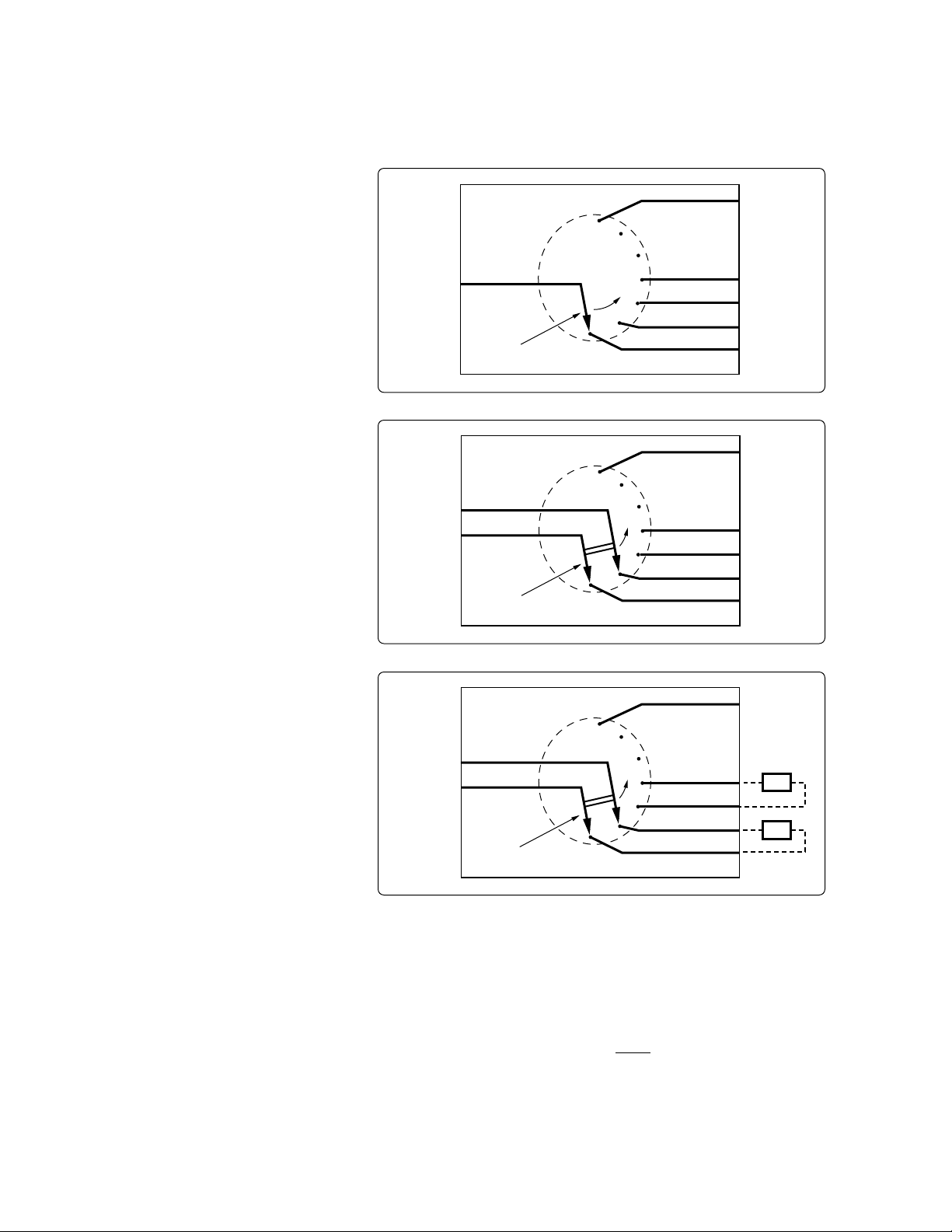
Switching Operation
The basic 1xN switching design
of the 8606xC is shown in
Figure 2. It consists of a single
input channel that is routed
through a movable arm. The arm
is controlled by the stepper
motor to align the input to any
output position1. Very low
insertion loss and excellent
repeatability are achieved
using high quality optics and
precise motor control.
A two input switch diagram is
shown in Figure 3. In this configuration, the two input arms
move together to connect
either input channel to an
output channel. The standard
8606xC design is called “nonblocking” since the unselected
input channel is not blocked
to the output. In this example,
connecting A1 to B1 may also
connect A2 to B2. “Blocking”
type switches that only allow
one of the input channels to be
connected to the output can
also be configured in the 8606xC
family. These are available as
special options at this time.
For additional information about
blocking switches, please refer
to the custom switching configuration section of this document or contact your local
Agilent field office.
Contiguous Switching Option
A variation on the two input
switch as in Figure 3, this option
allows both inputs to be connected to corresponding adjacent output channels. This is
true both mechanically and
programmatically. For example,
when selecting Input A1 to
Output B1 you will get an A1
to B1 port connection. In the
case of the contiguous option,
you will also get an A2 to B2
adjacent connection, even though
these connections were not
selected.
The standard version does not
guarantee that the non-selected
input channel will be adjacent
to the selected output channel.
Figure 4 demonstrates one
application for this option in
which multiple devices under
test have their inputs connected to the odd output channels
and their outputs connected
to the adjacent even output
channels. This enables multiple
products to be connected and
tested in parallel, which can
dramatically reduce test times.
1
The terms “input” and “output” denote
one side of the switch versus the other.
They do not imply that transmission can
only occur in one direction. The 8606xC
series switches are all bi-directional (i.e.,
signals can transmit in either direction).
Input
Channel
Output
Channels
Rotatable
Input Armature
A
B
B
B
B
B
N
4
3
2
1
.
.
.
1
Input
Channels
Output
Channels
Rotatable
Input Armature
A
B
B
B
B
B
N
4
3
2
1
.
.
.
1
A
2
Input
Channels
Output
Channels
Rotatable
Input Armature
A
B
B
B
B
B
N
4
3
2
1
.
.
.
1
A
2
DUT
DUT
Figure 2. 1xN switching configuration
Figure 3. 2xN non-blocking configuration
Figure 4. Contiguous switching option

4
A
1
A
1
A
2
A
A
2
A
1
Layer S1
Layer S2
Layer S3
Layer S4
B
2
B
1
B
2
B
1
B
8
B
3
B
2
B
1
B
8
B
3
B
2
B
1
.
.
.
.
.
.
1
Custom configurations
In addition to the many standard options, Agilent offers a
variety of custom configurations
to tailor the optical switch for
specific test applications.
Some of the more important
configurations are described
here. For information on other
types of custom switches,
please contact your local
Agilent field representative.
Multi-layered Switches
The 8606xC family offers multilayered switch configurations
in a single chassis. This provides added flexibility and
functionality while minimizing
rack or bench space. Integrated
multi-layer software can control up to 4 separate switch
layers in a single box. An
example of a 4 layer switch is
shown in Figure 5. It consists
of two 1x2 switches on layers
S1 and S2 and two 2x8 switches in layers S3 and S4 in a single chassis. The front panel
display in Figure 6 shows the
channel configuration in each
of the four layers.
Blocking Switches
In addition to the standard
“non-blocking” design, the
8606xC series switches can be
specified in a “blocking” configuration (i.e., only one input
channel can be connected to
the output). This is achieved
in two ways.
The first type of blocking
solution is where every other
output channel position is utilized (see Figure 7). In this
configuration only one input
channel can be connected to
an output channel, while the
other input is not aligned to
any connecting port. The advantage to this design is that low
insertion loss can be maintained.
However, the total number
of available output channels
is reduced by half. For the
8606xC family, the limit would
be 50 output channels in this
blocking configuration.
Figure 5. Multi-layered switch example
Figure 6. Layer S1 showing input side of automated testbed shown in Figure 2
▲
▲
OFF
-B2
-B1
A1-
SYSTEM
LOCAL HELP 7 8 9
4 5 6
1 2 3SAVE
RECALL
SWITCH
PORT
0 ENTER
ENTRY
S1
S2 S3 S4
86062C
Lightwave Switch

5
Input
Channels
Output
Channels
A
B
B
B
B
N
3
2
1
1
A
2
2 x N Switch
Note: The unselected input channel is NOT connected
to the output.
N
C
N
C
N
C
Input
Channels
Output
Channels
A
B
B
B
B
B
N
4
3
2
1
.
.
.
1
A
2
Layer 1 Layer 2
Splice
Input
Channels
Output
Channels
A
B
B
B
B
B
N
4
3
2
1
.
.
.
1
A
2
A
A
3
4
If more than fifty channels are
required, another blocking
solution is available in the “C”
version by adding an Mx1
switching element in front of a
1xN armature switch (See
Figure 8). The implication of
this design is that there is
slightly higher insertion loss
than the standard “C” specification, and the input/output
channels are controlled on
two separate layers via front
panel keys or remote control.
When programming the switch,
two SCPI commands are needed to connect a one of the
input channels to a desired
output channel.
More Than
Two Input Channels
The 8606xC family of switches
can be configured to have
more than 2 input channels.
Up to 4 input channels can be
accomodated. Figure 9 depicts
a 4xN configuration. In this
design, the four input arms
move together to connect any
input channel to any output
channel.
For other types of special
configurations (such as angled
connector contacts, enhanced
specifications, special fiber
type, etc.), please contact your
local Agilent field representative
or regional customer call center.
Figure 7. Agilent 8606xC blocking switch configuration 1
Figure 8. Agilent 8606xC blocking switch configuration 2
Figure 9. 4xN switch configuration

6
A well-implemented automated test system can help reduce
manufacturing costs. A wide
range of measurements can be
performed and recorded much
more rapidly, eliminating the
need to manually reset operating conditions. Automated
systems can be implemented
to reduce the necessary operator skill level and amount of
training required. They can
also reduce the time spent
recording, recovering, and
publishing test results.
Qualification testing can be
very expensive, with the additional cost of operating an
environmental chamber on
top of tying up lots of test
equipment for long periods to
test multiple devices. Figure 10
shows an automated environmental test system using two
86060C Lightwave Switches
and an 8153 Lightwave Multimeter with the 81554SM Dual
Laser Source module and the
81532A Power Sensor module.
Multiple devices are connected for the test (for example,
isolators, patchcords, or attenuators). Insertion loss is measured versus temperature.
Reference channels are used
for system calibration and to
compensate for system drift.
This system could be expanded to test return loss versus
temperature with the addition
of a coupler and a reflectance
standard. This test system can
also be set up using a single
86062C switch with two layers.
8153
LW Multimeter
with Dual Source
and Power Sensor
86060C
Lightwave
Switch
Environmental Test
Environmental Chamber
DUTs
Reference Channels
86060C
Lightwave
Switch
86140B Optical
Spectrum Analyzer
86120C
Multi-Wavelength Meter
1 x 12
Layer
2 x 48
Layer
Reference
8 Channel
WDM DUT #1
8 Channel
WDM DUT #2
8 Channel
WDM DUT #3
8 Channel
WDM DUT #5
8164A
Tunable Laser Source
83438A Opt. 009
Erbium ASE Source
11896A
Polarization Controller
1 x 2
Layer
86062C
3 Layer Switch
Increasing measurement
throughput by greatly reducing
time per test, a single automated test system can do the
work of several manual stations,
thereby reducing both cost
per test and the total capital
investment required for the
test.
Multi-port device testing can
complicate manufacturing
test. Flexible lightwave switch
configurations provide a versatile building block for test
systems design. Figure 11 shows
an eight channel WDM/router
test setup which uses a multilayered 86062C switch with
three switching modules. The
Agilent 11896A Polarization
Controller allows the devices
under test to be tested for
amplitude and wavelength
Applications
Figure 10. Insertion loss as a function of temperature
Figure 11. Eight channel WDM/router test setup

7
Transmitter Test
86140B
Optical
Spectrum
Analyzer
86100B
Digital
Communications
Analyzer
8504B
Precision
Reflectometer
71612C
Bit Error
Rate Tester
O/E
83446A
Lightwave
Clock/Data
Receiver
Reference Fiber
Long Fiber Length
86062C
Two Layer Switch
2 x N
Layer
2 x 4
Layer
Transmitters
Under Test
DUT
DUT
DUT
Ref Transmitter
polarization dependency. The
Agilent 86140B Optical Spectrum
Analyzer provides spectral
characteristics such as free
spectral range, channel bandwidth, and isolation/crosstalk.
The Agilent 86120C MultiWavelength Meter is used to
make extremely accurate
channel wavelength and channel spacing measurements.
The switch configuration provides for an 8 x 8 or multiple
1 x 8 test device configurations.
Products aimed at new telecommunications systems require
extensive testing to industry
standards such as ITU-TS
(formerly CCITT) G.957 for
the Synchronous Digital Hierarchy, and other standards for
SONET and ATM. Increasingly,
the performance of products
for these markets must be well
documented and supplied with
the product. Manufacturers
continue to strive to use testing
as one tool to improve process
performance and yields. Potential suppliers are carefully
evaluated to insure that their
products and components will
meet overall system performance
requirements. Environmental
tests are frequently necessary
to be certain that designs are
robust compared to the operating conditions that must be met.
Figure 12 shows a system for
performing extensive parametric
measurements, such as those
required for SDH and SONET,
on multiple transmitters. The
system provides for testing the
spectral characteristics with
the Agilent 86140B Optical Spectrum Analyzer. The system
performs eye-diagram measure-
ments using the Agilent 86100B
Digital Communications Analyzer
(DCA). The Agilent 8504B
Precision Reflectometer is
calibrated to remove the path
length to the transmitters, and
provides detailed measurement
of the different sources of
reflection in the transmitter.
The Agilent 71612C Bit Error
Rate Tester, together with the
Agilent 83446A Lightwave Clock/
Data Receiver, is used to monitor bit error rate performance.
The system can be expanded
to construct a transceiver test
system. Additional channels
would be needed on the right
hand switch. Microwave switching can be added in front of
the Agilent 71612C BERT to
sequentially measure the bit
error rate performance of the
receivers.
Figure 12. Automated transmitter test system

8
Specifications describe the instrument’s warranted performance (including measurement uncertainty) over the +5°C to +40°C temperature
range, with RH from 0 to 80%, except where noted. Characteristics provide information about non-warranted instrument performance in the
form of nominal values. Characteristics are at room temperature.
Characteristic Specification
Insertion Loss
1
Single-mode Switches 0.7 dB 1.0 dB
Multi-mode Switches 0.6 dB 0.8 dB
Insertion Loss Stability
2
±0.025 dB ±0.03 dB
Repeatability
3
Sequential Switching ±0.005 dB ±0.008 dB
Random Switching ±0.01 dB ±0.025 dB
Optical Return Loss
4
Single-mode Switches 62 dB 58 dB
Multimode Switches 25 dB 20 dB
Polarization Dependent Loss
5
0.02 dB 0.05 dB
Isolation –100 dB –80 dB
Typical Switching Life 10 million cycles
Switching Time
Between Adjacent Channels 330 msec
Each Additional Channel 50 msec
1
Insertion loss does not include connectors. Include an additional 0.25 dB
(characteristic) or 0.5 dB (hard spec) for each connector.
2
Drift of any channel relative to one assigned reference channel at ±3°C
for 7 days.
3
Repeatability measured after four hours warmup and with an one
second pause between movements.
4
Excludes external pigtail backscatter and connector reflections.
5
Polarization Dependent Loss only applies to single-mode switches and is
measured at 1550 nm.
General Specifications
Temperature Range:
Operational: 0 to +55°C
Storage: –40 to +70°C
Power Requirements:
100/115/230/240 V (range 90 to 254 vac).
Power Consumption: up to 80 VA (characteristic)
Weight: (dependent on the number of channels)
Agilent 86060C: 3.76 to 4.1 Kg (8.4 to 9.2 lbs)
Agilent 86061C: 4.0 to 6.18 kg (8.8 to 13.6 lbs)
Agilent 86062C: 7.72 to 13.74 Kg (17.25 to 30.7 lbs)
Dimensions: (H x W x D)
Agilent 86060C: 132.6 x 213 x 345.4 mm
(5.25 x 8.39 x 14 in.)
Agilent 86061C: 177 x 213 x 345.4 mm
(7 x 8.39 x 14 in.)
Agilent 86062C: 177 x 425 x 345.4 mm
(7 x 16.75 x 14 in.)
Specifications
and Characteristics

9
Switch Configuration
Chassis Size (choose one)
86060C Compact lightwave switch
86061C Mid-size lightwave switch
86062C Full-size lightwave switch
The following options are avilable for all models.
Number of Input Channels (choose one)
8606xC-001 Single input channel
8606xC-002 Two input channels
Wavelength and Fiber Type (choose one)
8606xC-109 1280–1650 nm, 9/125 µm single-mode fiber
8606xC-163 750–1350 nm, 62.5/125 µm multimode fiber
8606xC-H51 750–1350 nm, 50/125 µm multimode fiber
(special order)
Channel Location (choose one)
8606xC-050 Connectors on front panel
(86060C maximum 4 output channels,
86061C maximum 16 output channels)
8606xC-051 Connectors on rear panel
(for connectorized outputs only)
8606xC-052 3 meter fiber out the rear panel
(for connectorized outputs, connector
is at the end of the 3 meter fiber)
Optical Connectors (choose one)
8606xC-012 FC connector
8606xC-014 ST connector
8606xC-017 SC connector
Special Order FC/APC or SC/APC connectors
Accessories (choose one)
8606xC-1CM Rackmount flange kit
8606xC-1CN Front handle kit
8606xC-1CP Rackmount flange kit with handles
Documentation
8606xC-ABJ User’s manual in Japanese
8606xC-UK6 Commercial calibration certification with
test data
Special Orders
Contact your local Agilent Technologies representative.
Output Channels (choose one)
8606xC-2xx Where xx is the number of connectorized out-
put channels selected from the table below.
8606xC-3xx Where xx is the # of non-connectorized
output channels selected from the table
below. This option is used in conjunction
with the 8606xC-052 only.
86060C 86061C 86062C
Compact Mid-Size Full-Size
Lightwave Switch Lightwave Switch Lightwave Switch
Number of Output Channels
04 04 20
06 08 24
08 12 28
16 32
40
48
56
64
72
80
00 (100 ouput channels)
Ordering
Information

2. Select Switch Configuration
Select 1 x N or 2 x N Configuration
3. Select Wavelength Range and Fiber Type
Choose appropriate single-mode or multimode fiber
4. Select Port Type
Select termination location on front panel (channel numbers
may be limited), rear panel, or 3 meter fiber pigtail.
5A. Select the Number of Output Channels
Select from the available channel options.
5B. Select Connector Type
Select FC/PC, ST or SC Connectors.
Other connectors are available.
Contact your local Agilent representative.
5. Select the Number of Output Channels
Select from the available channel options.
Done
OR
For Connectorized Ports or Fibers For Bare Fiber Pigtails
1. Select Chassis Size
Select compact, mid-size or full-size chassis
Configuration Examples
Agilent 86060C Compact Lightwave Switch
86060C-001 One input channel
86060C-109 1280 to 1650 nm, 9/125 µm single-mode fiber
86060C-051 Connectors on rear panel
86060C-208 8 connectorized outputs
86060C-017 SC connectors
Agilent 86062C Full-Size Lightwave Switch
86062C-002 Two input channels
86062C-163 750 to 1350 nm, 9/125 µm single-mode fiber
86062C-052 3 meter fiber pigtails out the rear panel
86062C-264 64 outputs
86062C-012 FC connectors
Figure 13. Configuration flowchart
By internet, phone, or fax, get assistance with
all your test & measurement needs.
Online assistance:
www.agilent.com/comms/lightwave
www.agilent.com/find/emailupdates
Get the latest information on the
products and applications you select.
Phone or Fax
United States:
(tel) 1 800 452 4844
Canada:
(tel) 1 877 894 4414
(fax) (905) 282 6495
China:
(tel) 800-810-0189
(fax) 1-0800-650-0121
Europe:
(tel) (31 20) 547 2323
(fax) (31 20) 547 2390
Japan:
(tel) (81) 426 56 7832
(fax) (81) 426 56 7840
Korea:
(tel) (82-2) 2004-5004
(fax)(82-2) 2004-5115
Latin America:
(tel) (305) 269 7500
(fax) (305) 269 7599
Taiwan:
(tel) 080-004-7866
(fax) (886-2) 2545-6723
Other Asia Pacific Countries:
(tel) (65) 375-8100
(fax) (65) 836-0252
Email: tm_asia@agilent.com
Product specifications and descriptions in this document
subject to change without notice.
© 1999 Agilent Technologies, Inc.
Printed in USA June 12, 2002
5967-5902E
 Loading...