

Page 1

User’s Guide
HP 8591C
Cable TV Analyzer,
Spectrum Analyzer
Reference
Page 2

HP part number: 08591-90104
Printed in USA
March 1994
Notice.
The information contained in this document is subject to change without
notice.
Hewlett-Packard makes no warranty of any kind with regard to this material,
including but not limited to, the implied warranties of merchantability and
fitness for a particular purpose. Hewlett-Packard shah not be liable for errors
contained herein or for incidental or consequential damages in connection
with the furnishing, performance, or use of this material.
Regulatory Information.
The regulatory information is in the calibration guide for your analyzer.
@
Copyright Hewlett-Packard Company 1993, 1994
All Rights Reserved. Reproduction, adaptation, or translation without prior
written permission is prohibited, except as allowed under the copyright laws.
1400 Fountaingrove Parkway, Santa Rosa, CA 95403-1799, USA
Page 3

This Hewlett-Packard instrument product is warranted against defects in
material and workmanship for a period of one year from date of shipment
During the warranty period, Hewlett-Packard Company will, at its option,
either repair or replace products which prove to be defective.
For warranty service or repair, this product must be returned to a service
facility designated by HP Buyer shall prepay shipping charges to HP and HP
shall pay shipping charges to return the product to Buyer. However, Buyer
shall pay all shipping charges, duties, and taxes for products returned to HP
from another country.
HP warrants that its software and firmware designated by HP for use with
an instrument will execute its programming instructions when properly
installed on that instrument. HP does not warrant that the operation of the
instrument, or software, or firmware will be uninterrupted or error-free.
111
Page 4

Limitation of Warranty
The foregoing warranty shall not apply to defects resulting from improper
or inadequate maintenance by Buyer, Buyer-supplied software or
interfacing, unauthorized modification or misuse, operation outside of the
environmental specifications for the product, or improper site preparation
or maintenance.
NO OTHER WARRANTY IS EXPRESSED OR IMPLIED. HP SPECIFICALLY
DISCLAIMS THE IMPLIED WARRANTIES OF MERCHANTABILITY AND
FITNESS FOR A PARTICULAR PURPOSE.
iv
Page 5

Exclusive Remedies
THEREMEDIESPROVIDEDHEREINAREBUYER'SSOLEANDEXCLUSIVE
REMEDIES, HPSHALLNOTBELIABLEFORANYDIRECT,INDIRECT,
SPECIAL,INCIDENTAL,ORCONSEQUENTIALDAMAGES,WHETHER
BASEDONCONTRACT,TORT,ORANYOTHERLEGALTHEORY,
V
Page 6

Assistance
Product maintenance agreements and other
are available
Fbr
any assistance, contact
Ome.
for
Hewlett-Rxckard
products.
gour
nearest Hewlett-Packard Sales and Service
customer
assistance agreements
vi
Page 7

Safety Notes
The following safety notes are used throughout this manual. Familiarize
yourself with each of the notes and its meaning before operating this
instrument.
CAUTION
WARNING
The caution sign denotes a hazard. It calls attention to a procedure that,
if not correctly performed or adhered to, could result in damage to or
destruction of the instrument. Do not proceed beyond a caution sign until
the indicated conditions are fully understood and met.
The warning sign denotes a hazard. It calls attention to a procedure that,
if not correctly performed or adhered to, could result in injury or loss of
life. Do not proceed beyond a warning sign until the indicated conditions
are fully understood and met.
vii
Page 8

General Safety Considerations
WARNING
WARNING
CAUTION
WARNING
WARNING
Before this instrument is switched on, make sure it has been properly
grounded through the protective conductor of the ac power cable to a
socket outlet provided with protective earth contact.
Any interruption of the protective (grounding) conductor, inside or
outside the instrument, or disconnection of the protective earth terminal
can result in personal injury.
There are many points in the instrument which can, if contacted, cause
personal injury. Be extremely careful. Any adjustments or service
procedures that require operation of the instrument with protective
covers removed should be performed only by trained service personnel.
Before this instrument is switched on, make sure its primary power circuitry
has been adapted to the voltage of the ac power source.
Failure to set the ac power input to the correct voltage could cause damage to
the instrument when the ac power cable is plugged in.
No operator serviceable parts inside. Refer servicing to qualified
personnel. To prevent electrical shock, do not remove covers.
If this instrument is used in a manner not specified by Hewlett-Packard
,
Co., the protection provided by the instrument may be impaired.
Instruction Manual
The instruction documentation symbol. The product is marked with this symbol when it is necessary for the user
to refer to the instruction in the manual.
. . .
Vlll
Page 9

HP
8591C
Cable TV Analyzer
Documentation Description
The following guides are shipped with your HP
HP 8590 E-Series Sjxctrum
Analyze
and HP 8591C Cable TV Analyzer
8591C
cable TV analyzer:
Calibration Guide
Tells you how to test your spectrum analyzer to determine if the
spectrum analyzer meets its specifications.
HP 8591 C
CabLe
TV Analyzer User’s Guides
Cable TV Measurements
l Tells you how to make cable TV measurements with your analyzer.
l Describes the cable TV analyzer mode features.
Spectrum Analyzer Reference
l Tells you how to make measurements using the spectrum analyzer
mode.
l Describes the spectrum analyzer mode features.
l Tells you what to do in case of a failure.
HP 85916 Cable TV Analyzer Getting
l Describes how to make a simple measurement with your spectrum
Started
and Quick
Reference
Guide
analyzer.
l Briefly describes the cable TV and spectrum analyzer functions.
l Provides a quick reference for cable TV and spectrum analyzer softkeys.
HP 8590 E-Series and L-Series Spectrum Analyzers and HP
859lC Cable
TV Analyzer Programmer’s Guide
Describes analyzer operation via a remote controller (computer).
ix
Page 10

Options
Option 910: Additional User’s Documentation
Provides an additional copy of the user’s guides, the calibration guide,
and the quick reference guide.
Option 915: Assembly-Level and Component-Level Repair Service
Guides
Describes troubleshooting and repair of the spectrum analyzer.
Option 915 consists of two manuals:
HP 8590 E-Series and L-Series Spectrum Analyzers and HP 8591C
Cable TV Analyzer Assembly-Level Repair Service Guide
adjustment and assembly level repair of the analyzer.
HP 8590 E-Series and L-Series Spectrum Analyzers and HP 8591C
Cable TV Analyzer Component-Level Repair Service Guide
information for component-level repair of the spectrum analyzer.
describes
provides
X
Page 11

How to Order Manuals
Each of the manuals listed above can be ordered individually. To order,
contact your local HP Sales and Service Office.
xi
Page 12
Contents
1. Preparing For Use
What
You’ll
Introducing the
Preparing
Initial Inspection
Power
Setting the
Checking the
Power
Turning
Performing the Tracking-Generator Self-Calibration
Printing or Plotting
Printing
Interconnection and Printing Instructions
Plotting
Interconnection and Plotting Instructions
Printing
Interconnection and Printing Instructions
Plotting
Interconnection and Plotting Instructions
Printing Using
Interconnection and Printing Instructions
Plotting to an
Interconnection and Plotting Instructions
Printing after Plotting
Electrostatic Discharge
Reducing Damage Caused
Your
Requirements
Cable
on
the Analyzer
Routine
an
Equipment
Equipment
Equipment
Using an
Equipment
Equipment
Equipment
Find in This Chapter
HP
8591C Cable
Cable TV Analyzer
..................
.................
Line
Voltage Selector
Fuse
....................
.................
...................
for
.................
RS-232 Interface
...................
RS-232 Interface
...................
HP-IB Interface
...................
HP-IB Interface
...................
a
Parallel Interface
...................
HP
LaserJet Printer
...................
or
................
the First Time
Plotting after Printing
by ESD
...........
TV
Analyzer
for Use
Switch
.........
.........
..........
..........
..........
.........
..........
.......
.......
.......
.......
.......
.......
.......
.......
.......
....
...
l-2
1-2
l-4
l-5
l-7
l-8
1-9
l-11
1-13
1-15
1-17
1-17
1-17
1-18
l-22
l-22
1-22
l-25
1-25
l-30
l-30
l-30
l-33
1-33
l-33
l-37
1-37
l-37
1-38
l-39
1-39
Contents-l
Page 13
2. Getting Started
What You’ll Learn in this Chapter
Getting Acquainted
Front-Panel Features
Rear-Panel Features
Data Controls
Hold
Key
Knob
Number/Units Keypad
Step Keys
Fine-Focus Control
Screen
Menu
Making
Measurement Summary
Improving Accuracy with Self-Calibration Routines
Memory Card Insertion and Battery Replacement
Analyzer Battery Information
Annotation
and
Softkey Overview
a
Measurement
Warm-Up Time
Performing the Tracking Generator Self-Calibration
Routine (Option 011 only)
When Is Self-Calibration
Changing the Memory Card Battery
Procedure to Change the Memory Card Battery
with the
...................
....................
.....................
...................
..................
..................
Analyzer
................
................
..............
...............
...............
...............
Needed?
...........
..........
.............
............
..........
.............
.........
....
...
...
2-2
2-3
2-3
2-7
2-10
2-10
2-10
2-11
2-11
2-12
2-13
2-16
2-17
2-20
2-21
2-21
2-24
2-26
2-27
2-28
2-29
2-31
3.
Using Spectrum Analyzer Features
What You’ll Learn in This Chapter
Using
Use the Marker Table to
Use
Saving
Saving
Contents-2
..........
the Internal Preamplifier
List All
the Peak Table to
and Recalling Data from Analyzer Memory
To
Save a
To
Recall a
To
Save a
To Recall
To Save a
Factors
To Recall Limit-Line
Factors
To Protect Data From
State
State
Trace
a
Trace
Limit-Line Table
....................
....................
and Recalling Data from the Memory Card
List
..................
.................
..................
.................
Tables or
Being
............
the Active Markers
the Displayed
or
Amplitude Correction
Amplitude Correction
Overwritten
Signals
......
....
....
....
...
3-2
3-3
3-4
3-6
3-8
3-8
3-9
3-10
3-11
3-12
3-13
3-13
3-15
Page 14
Preparing the Memory Card
To Enter
To
To
To
To
To
To
To
To
Saving
To
To Recall
Using
Procedure
Limit-Line Functions
a Prefix
Save a
Recall a
Save a
Recall a
Save a
Recall a
Save
Limit-Line
Factors
Recall
Limit-Line
Factors
State
Trace
Display Image
...........
............
State
.................
..................
Trace
.................
Display Image
Tables or
....................
Tables or
....................
and Recalling Programs with
Save a
Program
a
Program
................
................
Limit-Line Functions
for
Creating
................
Editing, Creating,
Selecting the Type
or Viewing a
of
Selecting the Limit-Line
Selecting the Segment Number
Selecting the Frequency
Selecting the Amplitude Coordinate
Selecting the Segment Type
for Use
..............
.............
Amplitude Correction
Amplitude Correction
..............
an
Upper Limit
Limit-Line
Limit-Line Table
Table
Format
..........
or
Time Coordinate
............
.........
a
Memory Card
Line
........
Completing Table Entry and Activating Limit-Line
Testing
Saving
or
Procedure
Learn About the Analog+ Display
Learn About the Windows
Learn
How to
Procedure
Amplitude-Correction Functions
Editing
...................
Recalling Limit-Line
for
Creating
an
Display
Tables
Upper and
Mode
..........
Lower
........
Enter Amplitude Correction Factors
for
Creating Amplitude-Correction Factors
...........
or
Viewing the Amplitude-Correction
Selecting the Amplitude-Correction Point
Selecting the Frequency Coordinate
Selecting the Amplitude Coordinate
........
........
Completing Table Entry and Activating Amplitude
Corrections
Saving or
Recalling Amplitude Correction
.................
1 : 1
........
.....
.....
.......
.......
....
.......
Limit
Line
....
Tables
......
Tables.
3-17
3-19
3-20
3-21
3-22
3-23
3-24
3-25
3-26
3-27
.
3-28
3-29
3-30
3-33
3-34
3-39
3-39
3-40
3-41
3-43
3-44
3-44
3-46
3-48
3-48
3-49
3-52
3-54
3-57
.
3-58
3-61
.
3-61
3-61
3-63
3-63
3-64
.
3-64
Contents-3
Page 15
External Keyboard
Using the
External Keyboard Installation
To Enter
To Enter Programming Commands
To Enter
4.
Making Basic Measurements Using Spectrum Analyzer Mode
What You’ll Learn in This Chapter . . . . . . .- . . .
Resolving
Bandwidth Function . . . . . . . . . . . . . . .
Resolving
Resolution Bandwidth Function . . . . . . . . . .
Increasing the Frequency Readout Resolution
Marker Counter . . . . . . . . . . . . . . . . .
Decreasing the Frequency
Function . . . . . . . . . . . . . . . . . . . .
Tracking Unstable
Maximum
Comparing
Measuring
Bandwidth, and Video Averaging . . . . . . . . . .
Identifying Distortion Products
and
Distortion from the Analyzer . . . . . . . . . . . .
Third-Order Intermodulation Distortion . . . . . . .
Using
External Keyboard
a Screen
a Prefix
Signals of
Small Signals
Hold
Signals Using
Low-Level Signals Using
Traces . . . . . . . . . . . . . . . . . .
the Analyzer As
.................
..............
Title
................
Equal Amplitude
Hidden
Signals Using
and Minimum
a
.............
by
Span Using
Delta Markers . . . . . . . .
Using
Receiver in
..........
........
Using
Large
the Marker Track
Marker
Hold
Attenuation, Video
the
Zero
the Resolution
Signals Using
Using
Track
and the
Functions . . . .
RF
Attenuator
Frequency Span
the
the
.
3-65
3-68
3-68
3-68
3-69
3-69
4-2
4-3
4-6
4-9
4-11
4-13
4-18
4-22
4-30
4-30
4-34
4-37
5.
Making Measurements Using Spectrum Analyzer Mode
What You’ll Learn in This Chapter . . . . . . . . . .
Measuring Amplitude Modulation with the
Stimulus-Response Measurements . . . . . . . . . . .
Demodulating and Listening to an
Triggering
Using
Contents-4
Fast
Fourier
Transform Function . . . . . . . . . . . . . . . .
What Are Stimulus-Response Measurements? . . . . .
Using a
Stepping through the Measurement . . . . . . . . .
Tracking Generator Unleveled Condition . . . . . . .
Measurements (Option 107 only) . . . . . . . . . .
Spectrum Analyzer With
on a
Selected
the Gate Utility to
Line of a
Simplify
a
Tracking Generator
AM or FM Signal . .
Video Picture Field
Time-Gated
. .
5-2
5-3
5-12
5-12
5-14
5-15
5-22
5-23
.
5-26
5-28
Page 16

Using
Using
N
Percent Amplitude Modulation Measurement . . . . . .
Third Order Intermodulation Measurement (TOI) . . . .
Using
6.
Spectrum Analyzer Mode Key Descriptions
Service
Spectrum Analyzer
the Time-Gated Spectrum Analyzer Capability
Without the Gate Utility (Option 107 only) . . . . .
Introducing
Using
View
Example
Setting the Gate Delay and Gate Length Properly, When
NOT
Using
Spectrum Analyzer Capability (Option 107) . . . .
Performing
Spectrum Analyzer Capability (Option 107) . . . .
the
Bandwidth, Percent Amplitude Modulation, and Third
Order Intercept (TOI). . . . . . . . . . . . . . .
dB
the Power Measurement Functions to make
Transmitter Measurements . . . . . . . . . . . .
Occupied Bandwidth and Transmitter Frequency Error .
Adjacent Channel Power Ratio (ACP) . . . . . . . .
Channel Power Measurement . . . . . . . . . . . .
Service
Service
Service
the
Time-Gated Spectrum Analyzer Capability
the Time-Gated Spectrum Analyzer Capability to
Pulsed RF . . . . . . . . . . . . . . . .
of a
Time-Gated Pulsed RF
Using
the Self-Calibration Routines with Time-Gated
a
One
Bandwidth Measurement . . . . . . . . . . . .
Functions . . . . . . . . . . . . . . . . . .
Calibration Functions . . . . . . . . . . . .
Diagnostic Functions . . . . . . . . . . . .
Diagnostic Functions (continued) . . . . . .
the Gate Utility . . . . . . . . . . .
Functional
Button Measurements to Measure N
Mode
Check of
Functions . . . . . . . . . .
Signal. . . .
the Time-Gated
dB
5-33
5-34
5-37
.
5-40
5-50
5-54
5-56
5-59
5-60
5-62
5-64
5-67
5-68
5-70
5-74
6-3
6-3
6-4
6-5
6-6
7. Key Menus
8.
If You Have a Problem
What You’ll Find in This Chapter . . . . . . . . . . .
Calling
Before
HP Sales
You
Call
Check
If you suspect the analyzer configuration is wrong . . .
If the display position is
If the analyzer measurements appear
the
basics . . . . . . . . . . . . . . . .
and
Service
Hewlett-Packard . . . . . . . . . . .
Offices . . . . . . . . . .
offset . . . . . . . . . .
inaccurate . . . .
8-2
8-3
8-4
.
8-5
8-6
.
8-6
8-7
Contents-5
Page 17

If the error message
If the
calibration
If the calibration data is corrupt
If the display is scrambled
How to Call
Returning the Cable
Package the
Error
Messages
9. Options and Accessories
What You’ll Find in This Chapter
Options
Tracking Generator (Option 011)
Carrying
HP-IB Interface (Option 021)
Front Panel Protective
TV Receiver/Video Tester (Option 107)
Noise
Narrow Resolution Bandwidths (Option 130)
Rack
Rack Mount Kit With Handles (Option 909)
User’s Guides
Service
Accessories
RF
AC Power Source
External Keyboard
HP-IB Cable
Memory Cards
Plotter
Printer
Rack Slide
RS-232
Transit
Figure Card (Option 119)
Mount Kit without Handles (Option 908)
Bridges
Hewlett-Packard
cable TV
......................
Case, Color
Documentation (Option 915)
.....................
....................
......................
......................
Kit
Cable
Case
FREQ UNCAL
routines cannot
TV
...................
and Calibration Guide (Option 910)
.................
...................
..................
..................
...................
...................
stays on screen
be performed
..........
.............
............
Analyzer
analyzer
Tan (Option 015)
Cover
................
for Service
for
shipment
...........
..........
............
(Option 040)
...........
.........
.......
.......
......
......
.....
.....
.....
.....
....
....
...
8-7
8-8
8-8
8-8
8-10
8-12
8-12
8-14
9-2
9-3
9-3
9-3
9-3
9-4
9-4
9-4
9-5
9-5
9-6
9-6
9-6
9-7
9-7
9-7
9-8
9-8
9-9
9-9
9-10
9-10
9-10
9-10
Glossary
Index
Contents-6
Page 18

Figures
l-l. HP
l-2. Setting the Line Voltage Selector Switch
1-3. Checking the Line Fuse
l-4. Reference Connector
1-5. Example of a Static-Safe Work Station
2-
2-2. Rear-Panel Feature Overview
2-3. Adjusting the Fine Focus
2-4. Screen Annotation
2-5. Relationship between Frequency and Amplitude
2-6. Reading the Amplitude and Frequency
2-7. Inserting the Memory Card
2-8. Memory Card Battery Date Code Location
2-9. Memory Card Battery Replacement
2-10. Rear-Panel Battery Information Label
3-l.
3-2. Peak
3-3. Inserting the Memory Card
3-4. Typical Limit-Line Display
3-5. The Completed Limit-Line
3-6. Limit-Line Segments
3-7. Segment Types
3-8. Upper and Lower Limit-Line Testing
3-9. Analog+ Display Mode
3-10.
3-
11. Amplitude-Correction Display
3-12. Completed Amplitude-Correction
3-
13. Amplitude-Correction Points
4-l.
4-2. Resolving
4-3. Resolution Bandwidth Requirements for Resolving Small
4-4. Signal Resolution with a 10
4-5. Signal Resolution with a 30
4-6. Using the Marker Counter
4-7. After Zooming In on the Signal
4-8. Using Marker Tracking to Track an Unstable Signal
8591C
Cable TV Analyzer
................. l-9
...................
1. Front-Panel Feature Overview
.................
....................
................
Marker
Windows Display Mode
Set-Up for Obtaining Two Signals
Table
Table
Signals
Display
Display
.....................
Signals
of Equal Amplitude
.......................
..................
....................
................
................
Iable
...................
..................
.................
kHz
kHz
................
............... l-2
..........
........... l-40
..............
...............
......
..........
.........
............
...........
.............
............
...............
‘Ihble
...............
.............
Resolution Bandwidth ...
Resolution Bandwidth ...
..............
..........
...........
.....
l-8
1-13
2-3
2-7
2-12
2-13
2-18
2-20
2-27
2-29
2-30
2-31
3-4
3-6
3-17
3-35
3-38
3-43
3-47
3-51
3-53
3-54
3-57
3-60
3-62
4-4
4-5
4-6
4-7
4-8
4-10
4-12
4-15
Contents-7
Page 19

Contents
4-9. Viewing an Unstable Signal Using Max Hold A
.......
4-10. Viewing an Unstable Signal With Max Hold, Clear Write, and
Min Hold
4-
11. Placing a Marker on the CAL OUT Signal
4-12. Using the Marker Delta Function
4-13.
Using the Marker to Peak/Peak Function
4-14. Frequency and Amplitude Difference Between Signals
4-
15. Low-Level Signal
4-16. Using 0
4-17. Decreasing Resolution Bandwidth
4-18.
Decreasing Video Bandwidth
4-19. Using the Video Averaging Function
4-20.
Harmonic Distortion ...
......................
.........
.............
..........
....................
dl3
Attenuation
.....
.........
: :
.........
.......
............
....
: : : : :
4-21. RF Attenuation of 10 dB 1 : : : : 1 : : : : 1 : : : 1
4-22. No Harmonic Distortion
4-23. Third-Order Intermodulation Equipment Setup
4-24. Measuring the Distortion Product
4-25. Viewing an AM Signal
4-26. Measuring Modulation In Zero Span
5-1. FFT Annotation
.....................
5-2. Percent Amplitude Modulation Measurement
.................
.......
.............
..................
............
........
5-3. Block Diagram of a Spectrum-Analyzer/Tracking-Generator
Measurement System
5-4. Transmission Measurement Test Setup
5-5. Tracking-Generator Output Power Activated
.................
...........
........
5-6. Spectrum Analyzer Settings According to the Measurement
Requirement
....................
5-7. Decrease the Resolution Bandwidth to Improve Sensitivity .
5-8. Manual Tracking Adjustment Compensates for Tracking Error
5-9. Normalized Trace
5-10.
Measure the Rejection Range with Delta Markers
5-
11. Demodulation of an FM Signal
5-12. Continuous Demodulation of an FM Signal
5-13. Triggering on an Odd Field of a Video Format
5-14. Triggering on an Even Field of a Video Format
5-15. Time-Gate Utility Display
....................
......
..............
.........
.......
.......
................
5-16. Viewing Time-Sharing of a Frequency with an Oscilloscope
5-17. Viewing Time-Sharing of a Frequency with a Spectrum
Analyzer
......................
5-18. Pulse Repetition Interval and Pulse Width (with Two Signals
Present)
.......................
4-16
4-17
4-18
4-19
4-20
4-21
4-23
4-24
4-25
4-27
4-29
4-30
:
4-32
4-33
4-34
4-36
4-38
4-39
5-4
5-9
5-13
5-15
5-16
5-17
5-18
5-19
5-21
5-21
5-24
5-25
5-26
5-27
5-28
5-35
5-36
5-38
Contents-8
Page 20

Contents
5-19. Test Setup for Time-Gated Spectrum Analyzer Capability . .
5-20. Setting the Center Frequency, Span, and Reference Level
5-21. Setting the Sweep Time .................
5-22. Setting the Gate Delay and Gate Length Using an Oscilloscope
5-23. Using Time-Gating to View Signal 1 ............
5-24. Placing the Gate Output During the Second Signal .....
5-25. Viewing Both Signals with Time-Gating ..........
5-26. Gate Not Occurring During the Pulse ...........
5-27. Gate is Occurring at the Beginning of the Pulse .......
5-28. Self-Calibration Data Results ...............
5-29. Rear Panel Connections for Time-Gated Spectrum Analyzer
Capability ......................
5-30.
Gate On ........................
5-31. Using the Level Gate Control ...............
5-32. N dB Bandwidth Measurement ..............
5-33. Percent Amplitude Modulation Measurement ........
5-34. Third-Order Intermodulation Measurement .........
5-35. Occupied Bandwidth ...................
5-36. Adjacent Channel Power .................
5-37. Adjacent Channel Power Extended ............
5-38. Adjacent Channel Power Graph ..............
5-39. Channel Power .....................
5-40. Channel Power Graph ..................
6-l.
Memory Card Catalog Information .............
6-2. Analyzer Memory Catalog Information ...........
6-3. CATALOG ON EVENT Display
..............
6-4. Connecting a Printer to the analyzer ...........
5-41
5-43
5-44
5-45
5-47
5-48
5-49
5-50
5-51
5-55
5-56
5-57
5-58
5-60
5-62
5-65
5-69
5-71
5-72
5-72
5-75
5-76
6-27
6-29
6-33
6-48
Contents-9
Page 21
Tables
l-l. Accessories Supplied with the Cable TV Analyzer
l-2. Power Requirements
l-3. AC Power Cables Available
l-4. Setting of ThinkJet Printer Mode Switches
1-5. Static-Safe Accessories
2-l. Screen Annotation for Trace, Trigger, and Sweep Modes ...
2-2. Screen Annotation
3-
1. Summary of Save and Recall Operations, Analyzer Memory
3-2. Comparison of Analyzer Memory and Memory Card Operations
3-3. Save and Recall Functions Using Memory Card
3-8. External Keyboard Functions
5-l. Determining Spectrum Analyzer Settings for Viewing a Pulsed
RF Signal
5-2. Pulse Generator Test Setup Settings
5-3. Signal Generator Test Setup Settings
5-4. Gate Delay, Resolution Bandwidth, Gate Length, and Video
Bandwidth Settings
5-5. Sweep Time Settings
6-l. Commands Not Available with Analog+ Operation
6-2. Memory Card Catalog Information
6-3. Analyzer Memory Catalog Information*
6-4. CATALOG ON EVENT Display Description
6-5. Default Configuration Values
6-6. Compatibility of FFT With Other Functions
6-7. Commands Altered/Not Available within the Gate Utility
6-8. Functions Which Exit The Windows Display Format
6-9.
6-10.
6-11. Common Preset Conditions
6-12. Preset Conditions for All Models
8-l.
9- 1.
............................
Model Specific Preset Conditions
Hewlett-Packard Sales and Service Offices
............................
......................
...................
................
.................. l-40
....................
...............
............
............
..................
..................
.............
..........
.........
...............
............. 6-l
................
............. 6-l
.........
......
.........
.......
.....
........
.....
. .
l-6
l-7
1-12
l-26
2-14
2-15
3- 14
3-16
3-31
3-65
5-39
5-42
5-42
5-52
5-53
6-15
6-27
6-29
6-32
6-51
6-71
6-79
6-105
6-108
13
6-113
15
8-11
9-9
Contents- 10
Page 22

1
Preparing For Use
Page 23

Preparing For Use
What You’ll
Find in This
Chapter
This chapter describes the process of getting the cable TV analyzer ready
to use when you have just received it. See “Preparing Your Analyzer For
Use” for the process steps. The process includes initial inspection, setting
up the unit for the selected ac power source, and performing automatic
self-calibration routines. Information about static-safe handling procedures is
also included in this chapter.
Introducing the HP 8591C Cable TV Analyzer
l-2
Figure l-l. HP
9591C
Cable TV Analyzer
Page 24

Preparing For Use
The HP
that covers the 1 MHz to 1.8
8591C
cable TV analyzer is a small, lightweight test instrument
GHz
frequency range. The HP
8591C
cable TV
analyzer is a portable instrument ideal for field use. It comes in a durable
carrying case that makes it easy to transport and protects it from moisture
and dirt. The cable TV analyzer is fully operational within the case so you
never need to remove it.
The HP
8591C
cable TV analyzer comes equipped with the HP
85721A
cable TV measurements and system monitor personality installed. The
cable TV measurements and system monitor personality is a downloadable
program (DLP) consisting of measurement routines useful for cable television
applications.
l-3
Page 25

Preparing Your Cable TV Analyzer for Use
Detailed information for all of the steps in this process is included in this
chapter immediately following the process description.
1. Unpack the cable TV analyzer from the shipping container and inspect it
for damage during shipping.
2. Verify that all of the accessories and documentation has been shipped.
3. Check that the line voltage selector on the rear panel is set to the proper
voltage for your area.
4. Check that the correct fuse is in place.
WARNING
Failure to ground the cable TV analyzer properly can result in personal
injury. Use an ac power outlet that has a protective earth contact. DO
NOT defeat the earth grounding protection by using an extension cable,
power cable, or autotransformer without a protective ground conductor.
5. Connect the power cable to the cable TV analyzer and press the front
panel
m
switch to turn it on.
6. Execute the self-calibration routines after allowing the cable TV analyzer
to warm up for 30 minutes. Chapter 2 includes guidelines on how often
the routines should be performed.
7. Connect CAL OUT to INPUT 75
OUTPUT is connected to
8. Press (CAL) then CAL
amplitude self-calibration routines. Press CAL STOKE when the routine is
finished.
9. For tracking generator Option 011, connect the RF OUT 75 61 to the INPUT
75 61 then press More i of 4, More 2 of 4, and CAL TRK
run the self-calibration routine. Press
routine is finished.
EXT
FREQ Q
62.
Check that the rear panel
REF IN.
AMPTD to perform the frequency and
ICAL)
and CAL STORE when the
l0MHz
EEM
to
l-4
Page 26

Initial Inspection
Inspect the shipping container for damage. If the shipping container
or cushioning material is damaged, keep it until you have verified that
the contents are complete and you have tested the cable TV analyzer
mechanically and electrically.
lhble
l-l contains the accessories shipped with the cable TV analyzer. If
the contents are incomplete or if the cable TV analyzer does not pass the
verification tests in the calibration guide, notify the nearest Hewlett-Packard
office. If the shipping container is damaged or the cushioning material shows
signs of stress, also notify the carrier. Keep the shipping materials for the
carrier’s inspection. The HP office will arrange for repair or replacement
without waiting for a claim settlement.
If the shipping materials are in good condition, retain them for possible future
use. You may wish to ship the cable TV analyzer to another location or to
return it to Hewlett-Packard for service. See “How to Return Your Analyzer
for Servicing, D in Chapter 8 for more information about shipping materials.
NOTE
Complete instructions for installing your cable TV analyzer in an equipment rack are provided in a
service note that is included with Options
I
1CM
and
ICN
Rack Mounting Kits.
,
l-5
Page 27
Preparing For Use
Initial Inspection
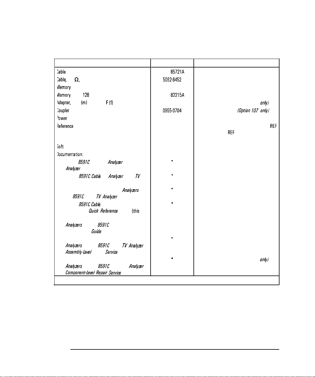
Table l-l. Accessories Supplied with the Cable TV Analyzer
Description
Zabla TV RF/video measurements personality
Zable, 75 0, BNC
Memory card holder
vlemory card,
idapter,
BNC
128
kilobyte
iml
to Type F
If]
loupIer
lower cable
leference
connector
ioft carrying pack
HP Part Number
HP
B5721A
5062-6452
9222-1545
HP
82215A
1250-2477
0955-0704
See Table 1-3.
1250-1499
9211-7102
Iocumentation:
l HP
8591C
Ana&er
Reference User’s Guide
l HP
859iC Cabb
Cable TV
TV
Ana@r
Analyzer
Spectrum
Cable
TV
I
I
Measurements User’s Guide
l HP 8590 E-Series Spectrum
HP
8591C
Cable TV
l HP
8591C Cabh
Started and
l
HP 8590 E-Series and L-Series Spectrum
Ana&ers
and HP
Programmer’s
l
HP 8590 E-Series and L-Series Spectrum
Ana&ers
and HP
Assembiy-level
l
HP 8590 E-Series and L-Series Spectrum
Ana&ers
and HP
Comoonenthel
Analyzer
TV Analyzer Getting
hick Referent
8591C
Guide
8591C
Repair
8591C
Reuair
Ana@rs
Calibration Guide
Guide
Cable TV Analyzer
Cable TV
Servhe
Cable TV
Serhe
Ana&er
Guide
AnaQzer
Guide
[this
and
book]
”
x
l
x
I(
Contact your nearest sales and service center for current part number.
Comments
Shipped with analyzer.
Shipped with analyzer.
Shipped with analyzer.
Shipped with analyzer.
Shipped with analyzer. /Option 107 only/
Shipped with analyzer.
/Option 107 onb/
Shipped with analyzer.
Shipped connected between the 10 MHz
OUT and the EXT
REF
IN on the rear panel
of the analyzer.
Shipped with analyzer.
Shipped with analyzer.
Shipped with analyzer.
Shipped with analyzer.
Shipped with analyzer.
Shipped with analyzer.
Shipped with analyzer. /Option 915 on/y/
Shipped with analyzer. /Option 915
on&
REF
1-6
Page 28
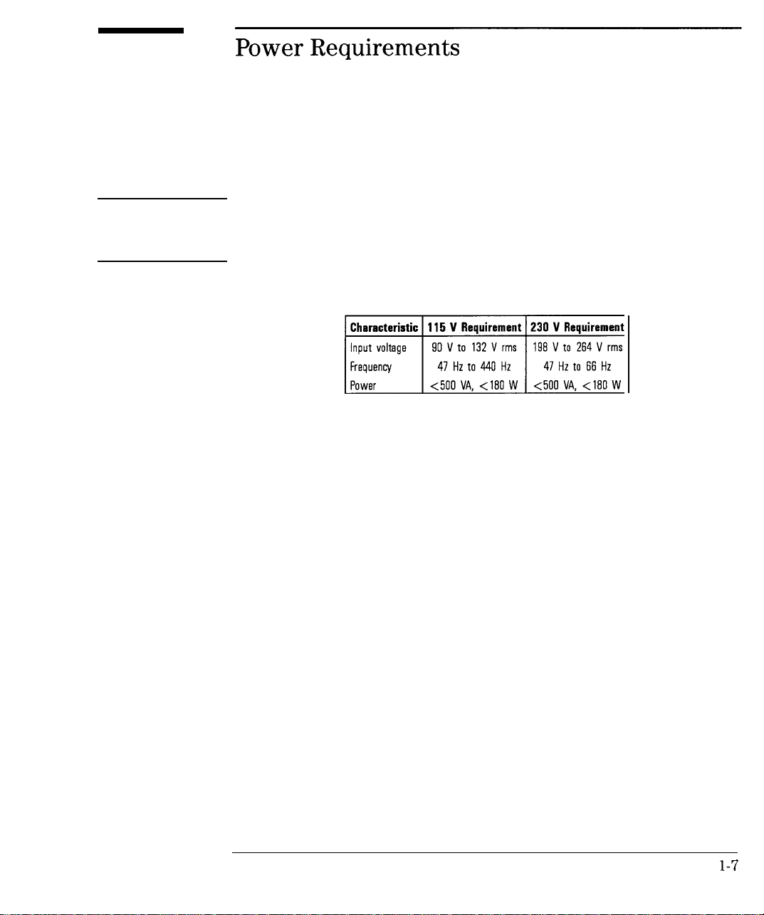
Power Requirements
The cable TV analyzer is a portable instrument and requires no physical
installation other than connection to a power source.
CAUTION
Do not connect ac power until you have verified that the line voltage is
correct, the proper fuse is installed, and the line voltage selector switch is
properly positioned, as described in the following paragraphs. Damage to the
equipment could result.
Table 1-2. Power Requirements
l-7
Page 29

Preparing For Use
Power Requirements
Setting the Line Voltage Selector Switch
Figure
l-2.
Setting the line Voltage Selector Switch
CAUTION
Before connecting the cable TV analyzer to the power source, you must set
the rear-panel voltage selector switch correctly to adapt the cable TV analyzer
to the power source. An improper selector switch setting can damage the
cable TV analyzer when it is turned on.
Set the instrument’s rear-panel voltage selector switch to the line voltage
range (115 V or 230 V) corresponding to the available ac voltage. See
Figure l-2. Insert a small screwdriver or similar tool in the slot and slide the
switch up or down so that the proper voltage label is visible.
1-8
Page 30

Checking the Fuse
Figure 1-3. Checking the Line Fuse
Preparing For Use
Power Requirements
The recommended fuse is size 5 by 20 mm, rated
F5A,
250 V (IEC approved).
This fuse may be used with input line voltages of 115 V or 230 V. Its HP part
number is 2110-0709.
With an input line voltage of 115 V an alternate fuse can be used. In areas
where the recommended fuse is not available, a size 5 by 20 mm, rated fast
blow, 5 A, 125 V
number is
2110-0756.
(UL/CSA
approved) fuse may be substituted. Its HP part
The line fuse is housed in a small container beside the rear-panel power
connector (see Figure l-3). The container provides space for storing a spare
fuse, as shown in the figure.
l-9
Page 31

Preparing For Use
Power Requirements
To check the fuse, insert the tip of a screwdriver in the slot at the middle of
the container and pry gently to extend the container.
NOTE
The fuse container is attached to the line module; it cannot he removed.
The fuse closest to the cable TV analyzer is the fuse in use. If the fuse is
defective or missing, install a new fuse in the proper position and reinsert the
fuse container.
l-10
Page 32

Preparing For Use
Power Requirements
Power Cable
The cable TV analyzer is equipped with a three-wire power cable, in
accordance with international safety standards. When connected to an
appropriate power line outlet, this cable grounds the instrument cabinet.
WARNING
Failure to ground the cable TV analyzer properly can result in personal
injury. Before turning on the cable TV analyzer, you must connect its
protective earth terminals to the protective- conductor of the main power
cable. Insert the main power cable plug only into a socket outlet that has
a protective earth contact. DO NOT defeat the earth-grounding protection
by using an extension cable, power cable, or autotransformer without a
protective ground conductor.
If you are using an autotransformer, make sure its common terminal is
connected to the protective earth contact of the power source outlet
socket.
Various power cables are available to connect the cable TV analyzer to the
types of ac power outlets unique to specific geographic areas. The cable
appropriate for the area to which the cable TV analyzer is originally shipped
is included with the unit. You can order additional ac power cables for use
in different areas.
‘fable
l-3 lists the available ac power cables, illustrates the
plug configurations, and identifies the geographic area in which each cable is
appropriate.
l-11
Page 33

Preparing For Use
Power Requirements
Table 1-3. AC Power Cables Available
PLUG TYPE * *
250v
250V
250V
125v
250V
CABLE
HP PART
NUMBER
8120-1351
8120-1703
8120-1369
8120-0696
8120-1689
8120-1692
8120-1348
8120-1538
8120-1378
8120-4753
8120-1521
8120-4754
81x-5182
8120~5181
DESCRIPTION
Strafght*
Qb
Straight*
90’
Straight* CEE7-Y11
90’
Straight*
90’
Straight*
Straight
9090’
Straight*
go0
PLUG
BS1363A
NZSS198/ASC112
NEMAS-15P
NEMAS-15P
NEMAS-ISP
CM (
229 (90)
229 (90)
201 (79)
221 (87)
201 (79)
201 (79)
203 (80)
203 (80)
203 (80)
230 (90)
203 (80)
230 (90)
200 (78)
200 (78)
CABLE
LENGTH
INCHES)
CABLE
COLOR
Mint Gray
Mint Gray Cyprus. Nigeria.
M,“, Gray East and west
Min, Gray Europe, Central
BI oci
BIOCk
Jade Gray
Jade Gray
Jade Gray
Jade Gray
Jade Gray
Jade Gray
FOR USE
IN COUNTRY
Great Eritafn.
Slngopore.
L
lmbabwe
African Republic
United ArOb
Republic
(unpolarized
many natIons)
United States
CCl”Od0.
Japan (100 v or
200
v), Bra2 II,
Colombia.
Phi I ,ipines,
Saudia Arabia.
TOIWO”
Israel
in
Mexico
* Part number for plug is industry identifier
HP Part Number for complete cable, including plug
+t
E =
Earth Ground; L = Line:
1-12
N =
Neutral.
for plug only. Number shown for cable is
Page 34

Turning on the Analyzer for the First Time
When you turn the cable TV analyzer on for the
first
time, you should
perform frequency and amplitude self-calibration routines to generate
correction factors and indicate that the unit is functioning correctly. The
cable TV analyzer should be allowed to warm-up for 30 minutes before
performing the self-calibration routines. See “When Is Self-Calibration
Needed?” in Chapter 2 for helpful guidelines on how often the self-calibration
routines should be performed.
Perform the following steps:
1. Ensure the reference connector is connected between the 10 MHz OUTPUT
and EXT REF IN rear-panel connectors. See Figure l-4.
:E
,R
Figure 1-4. Reference Connector
If you wish to use an external 10 MHz source as the reference frequency,
disconnect the reference connector from the rear-panel and connect an
external reference source to the EXT REF IN connector on the rear panel.
2. Plug the power cord into the cable TV analyzer.
3. Press
ILINE).
After a few seconds, the screen displays the Ermware revision date in the
YYMMDD format. For example, 930522 indicates May 22, 1993. The baud
rate
(RS232
: XXXX) is also displayed.
If your cable TV analyzer is equipped with Option 021 (HP-IB interface),
the appropriate interface address (HP-IB ADRS : XX) in place of the baud
rate, also appears on the screen.
Page 35

Preparing For Use
Turning on the Analyzer for the First Time
NOTE
Record the firmware date and keep it for reference. If you should ever need to call Hewlett-Packard
for service or with any questions regarding your cable TV analyzer, it will be helpful to have the
firmware date readily available.
4. To meet cable TV analyzer specifications, allow a 30 minute warm-up
before attempting to make any calibrated measurements. Be sure to
calibrate the cable TV analyzer only
U&Y
the cable TV analyzer has met
the operating temperature conditions.
5. Connect the 75 0 coaxial cable between the front-panel CAL OUT and the
INPUT 75 D connector.
NOTE
Remove all connections to the GATE TRIGGER INPUT rear-panel connector before performing the
self-calibration routines.
6. Perform the frequency and amplitude self-calibration routine by pressing
(CAL) and CAL FREQ & AMPTD
During the frequency routine, CAL : SWEEP, CAL :
FREQ,
and CAL : SPAN
and CAL: FM GAIN + OFFSET are displayed as the sequence progresses.
During the amplitude routine, CAL ; AMPTD, CAL : 3 dB BW, CAL :
and CAL :
LOGAMP
are displayed as the sequence progresses. CAL : DONE
ATTEN,
appears when the routine is completed. Any failures or discrepancies
produce a message on the screen; see Chapter 8.
1-14
Page 36

Preparing For Use
Turning on the Analyzer for the First Time
7. When the frequency and amplitude self-calibration routines have
been completed successfully, store the correction factors by pressing
CAL STORE.
The self-calibration routines calibrate the cable TV analyzer by generating
correction factors. The softkey CAL STOKE stores the correction factors
in the area of cable TV analyzer memory that is stored when the cable TV
analyzer is turned off; the cable TV analyzer will automatically apply these
factors in future measurements. If CAL STOKE is not pressed, the correction
factors remain in effect until the cable TV analyzer is turned off.
Performing the Tracking-Generator Self-Calibration Routine
For cable TV analyzers with Option 011, the tracking-generator
self-calibration routine should be performed prior to using the tracking
generator.
NOTE
Since the tracking generator calibration routine depends on the accuracy of the absolute amplitude level
of the cable TV analyzer, the cable TV analyzer amplitude calibration should be done prior to using
CAL TRK
GEN
l-15
Page 37

Preparing For Use
Turning on the Analyzer for the First Time
1. To calibrate the tracking generator, connect the tracking generator output
(RF OUT 75
a2)
to the cable TV analyzer INPUT 75 D connector, using an
appropriate cable.
NOTE
A low-loss cable should be used for accurate calibration. Use the 75 0 cable shipped with the cable
TV analyzer.
2. Press the following cable TV analyzer keys:
More 2 of 4 , then CAL
TRK
GEM TG SIGNAL NOT FOUND will be
ICAL),
More 1 of 4 ,
displayed if the tracking generator output is not connected to the cable TV
analyzer input.
3. To store this data in the area of cable TV analyzer memory that is stored
when the cable TV analyzer is turned off, press CAL STORE
When the self-calibration routines have been completed successfully, the cable
TV analyzer is ready for normal operation.
1-16
Page 38

Equipment
Printing or Plotting
You may wish to obtain a permanent record of data displayed on the cable
TV analyzer screen. This can be done using the (copy) key of the cable TV
analyzer, and a printer or plotter.
Printing Using an RS-232 Interface
l HP
8591C
cable TV analyzer.
l HP
13242G RS-232
cable
l Printer with
q HP 500,
q
HP 2225
q HP
q
HP LaserJet
q
LQ-570
q
MX-80
3630A
Epson
Epson
RS-232
5OOC*,
ThinkJet
PaintJet
interface, choose one of the following:
and
* Supports color printing
55OC*
DeskJet
1-17
Page 39

Preparing For Use
Printing or Plotting
Interconnection and Printing Instructions
1. Turn off the cable TV analyzer and the printer.
NOTE
The
RS-232
interface allows only one device (either the printer or the plotter) to be connected to the
cable TV analyzer. Refer to the programmer’s guide for more information on
wiring.
RS-232
protocol and cable
2. Connect the printer using an
RS-232
cable.
3. Turn on the cable TV analyzer and printer.
4.
Press @%FiQ, More
5.
To set the baud rate to 9600 baud, press BAUD RATE, 9600,
1
of 3
the baud rate to 1200 baud, press: BAUD RATE , 1200, (Hz).
I
NOTE
Some of the programs in this manual utilize 1200 baud. If your system uses the
lines, you can use 9600 baud for all of the programs.
6. Press
@%?@,
Print Conf
fg
.
IHz).
RS-232
To set
I
handshake
1-18
Page 40

Preparing For Use
Printing or Plotting
7. Select the configuration for your printer by pressing the appropriate key.
Note that the softkey is activated when the key title is underlined.
Set
Colr
Printer
NOTE
To proceed with the three printouts per page format, after printing one printout per page, it is
necessary to press PRINTER SETUP Pressing PRINTER SETUP resets the internal
counter.
Press this key to print in color if the cable TV
analyzer is connected to a Hewlett-Packard color
printer, then select the appropriate printer,
Selecting any Hewlett-Packard printer results in
three printouts per page prior to formfeeding the
page.
One printout per page can be achieved by
manually formfeeding each printout.
I
1-19
Page 41

Preparing For Use
Printing or Plotting
Set
B&W
Printer
Press this key to print in black and white, then
press one of the following keys to select the
appropriate printer mode.
l Press BP B&W PRINTER if the cable TV
analyzer is connected to a Hewlett-Packard
printer.
Selecting any Hewlett-Packard printer results in
three printouts per page prior to formfeeding
the page.
One printout per page can be achieved by
manually formfeeding each printout.
NOTE
To proceed with the three printouts per page format, after printing one printout per page, it is
necessary to press PRINTER SETUP . Pressing PRINTER SETUP resets the internal
counter.
l-20
l Press EP
analyzer is connected to a
MX80
SML LRG if the cable TV
MX-80
Epson or
other compatible B-pin print-head printer.
Pressing this key to underline SML will print
two printouts to a page and will print softkey
labels if desired. See step 8
Pressing this key to underline LRG will print
only one printout to a page and will not print
the softkey labels.
Page 42

Preparing For Use
Printing or Plotting
l Press
RP LQ570
SML LRG if the cable TV
analyzer is connected to a
other compatible
24-pin
print-head printer.
LQ-570
Epson or
Pressing this key to underline SML will print
two printouts to a page and will print softkey
labels if desired. See step 8
Pressing this key to underline LRG will print
only one printout to a page and will not print
the softkey labels.
8. If you want the softkey labels to be printed with the cable TV analyzer
display printout, press PRT MENU ON OFF so that ON is underlined. Note
that this function does not work when EP
MX80
LRG or EP
LQ570
LRG
is pressed.
9.
Press Previous Menu, COPY DEV PRMT PLT (PRNT should be
underlined), then
[copy_).
1-21
Page 43

Preparing For Use
Printing or Plotting
Plotting Using an RS-232 Interface
Equipment
l HP
8591C
cable TV analyzer.
l HP
13242G RS-232
l Any of the following Plotters:
q HP
q HP
q HP
q
7440A ColorPro
7445A
7550A/B
HP LaserJet
cable
plotter with an
plotter with an
plotter with an
RS-232
RS-232
RS-232
interface.
interface.
interface.
Interconnection and Plotting Instructions
1. Turn off the cable TV analyzer.
NOTE
The
K-232
interface allows only one device (either the printer or the plotter) to be connected to the
cable TV analyzer. Refer to the Programmer’s Guide for more information on IX-232 protocol and
cable wiring.
2. Connect the plotter using an
RS-232
cable.
3. Turn on the cable TV analyzer and the plotter.
4.
Press
[CONFIG),
More 1 of 3
l-22
Page 44

Printing or Plotting
5.
To set the baud rate to 9600 baud, press: BAUD RATE , 9600, (Hz).
NOTE
The HP
7470A
HP
8591C
cable TV analyzer, you can select one plot per page or four plots per page, but not two
plots per page.
plotter does not support two plots per page. If you use an HP
7470A
Preparing For Use
plotter with an
6. Press
(j-1,
Plot Conf ig . You can choose a full-page, half-page,
or quarter-page plot with the
PLTWPG
1 2 4 to underline the number of plots per page desired.
PLTWPC I
2 4
softkey.
Press
7. If two or four plots per page are chosen, a function is displayed that allows
you to select the location on the paper of the plotter output. If two plots
PLT Cl
per page are selected, then the LDC _ _function is displayed. If four
PLT Cl _
plots per page are selected, then the LOC _
is displayed. Press the
_
softkey until the rectangular marker is in the desired section of softkey
label. The upper and lower sections of the softkey label graphically
represent where the plotter output will be located.
l-23
Page 45

Preparing For Use
Printing or Plotting
Note that for a multi-pen plotter, the pens of the plotter draw the different
components of the screen as follows:
Description
Draws the annotation and graticula.
Draws trace A.
Draws trace
Draws trace C and the display line.
Draws user-generated graphics and the lower-limit linf
Draws the upper-limit line.
6.
8. Press Previous Menu, COPY DEV PRMT PLT (so that PLT is
underlined), then
[Copy).
l-24
Page 46

Printing Using an HP-IB Interface
Preparing For Use
Printing or Plotting
Equipment
l HP
8591C
cable TV analyzer equipped with Option 02
l HP 10833 (or equivalent) HP-IB cable.
l Printer with HP-IB interface, choose one of the following:
q HP
q HP
q
q HP
q HP LaserJet (with HP-IB to Centronics converter) t
q
q
310*
Portable DeskJet (with HP-IB to Centronics converter) t
55OC*
DeskJet (with HP-IB to Centronics converter) t
HP 2225
MX-80
LQ-570
ThinkJet
3630A
PaintJet
Epson (with HP-IB to Centronics converter) t
Epson (with HP-IB to Centronics converter) t
1.
* Supports color printing
t
Part number HP 922035 (US and Canada), and part number HP
(international)
Interconnection and Printing Instructions
92203K
1. Turn off the printer and the cable TV analyzer.
2. Connect the printer to the cable TV analyzer using the HP-IB cable. The
ThinkJet printer’s mode switches must be set correctly for use with the
cable TV analyzer. Refer to Table l-4 for the correct settings.
1-25
Page 47

Preparing For Use
Printing or Plotting
Table 1-4. Setting of
Switch
Number
Setting
1
down
2
down
3
“P
down
4
down
5
ThinkJet
Printer Mode Switches
Comments
Printer performs a carriage return only.
Printer oerforms a line feed
onlv.
Sets the printer to skip paper perforations
Sets the printer for a paper length of 11 inches.
Sets the printer to HP MOOE.
“P
down
Sets the printer to
USASCII.
down
NOTE
Because HP-IB cables can be connected together, more than one instrument can communicate on the
HP-IB. This means that both a printer and a plotter can be connected to the cable TV analyzer
two HP-IB cables). Each device must have its own
HP-18
address.
(using
Disconnect or turn off the computer
Because the cable TV analyzer cannot print with two controllers (the computer and the cable TV
analyzer) connected, the computer must be disconnected from the HP-IB. In most cases, it is sufficient
to simply turn the computer OFF.
3. Turn on the cable TV analyzer and printer.
4.
On the cable TV analyzer, press
[CONFIG),
Print
Config
1-26
Page 48

Preparing For Use
Printing or Plotting
5.6.The printer usually resides at the first device address. To enter address 1
for the printer, press PRINTER ADDRESS , 1,
Select the configuration for your printer by pressing the appropriate key.
Note that the softkey is activated when the key title is underlined.
(%J.
Set
Colr
Printer
NOTE
To proceed with the three printouts per page format, after printing one printout per page, it is
necessary to press PRINTER SETUP Pressing PRINTER SETUP resets the internal
counter.
Press this key to print in color if the cable TV
analyzer is connected to a Hewlett-Packard color
printer, then select the appropriate printer.
Selecting any Hewlett-Packard printer results in
three printouts per page prior to formfeeding the
page.
One printout per page can be achieved by
manually formfeeding each printout.
I
I
l-27
Page 49

Preparing For Use
Printing or Plotting
Set B&W Printer
Press this key to print in black and white, then
press one of the following keys to select the
appropriate printer mode.
l Press HP B&W PRINTER if the cable TV
analyzer is connected to a Hewlett-Packard
printer.
Selecting any Hewlett-Packard printer results in
three printouts per page prior to formfeeding
the page.
One printout per page can be achieved by
manually formfeeding each printout.
NOTE
To proceed with the three printouts per page format, after printing one printout per page, it is
necessary to press PRINTER SETUP Pressing PRINTER SETUP resets the internal
counter.
1-28
l Press EP
analyzer is connected to a
MX80
SML LRG if the cable TV
MX-80
Epson or
other compatible B-pin print-head printer.
Pressing this key to underline SML will print
two printouts to a page and will print softkey
labels if desired. See step 7.
Pressing this key to underline LRG will print
only one printout to a page and will not print
the softkey labels.
Page 50

Preparing For Use
Printing or Plotting
l Press
EP Lq5i’O
SML LRG if the cable TV
analyzer is connected to a
other compatible
24-pin
print-head printer.
LQ-570
Epson or
Pressing this key to underline SML will print
two printouts to a page and will print softkey
labels if desired. See step 7.
Pressing this key to underline LRG will print
only one printout to a page and will not print
the softkey labels.
7. If you want the softkey labels to be printed with the cable TV analyzer
display printout, press PRT MENU ON OFF so that ON is underlined.
Note that this function does not work when EP
EP
Lq570
SML LRG are pressed to underline LRG.
8.
Press Previous Menu, COPY DEV PRNT PLT (PRNT should be
MX80
SML LRG or
underlined), then IcoPv].
1-29
Page 51

Preparing For Use
Printing or Plotting
Plotting Using an HP-IB Interface
NOTE
The HP
7470A
plotter does not support 2 plots per page. If you use an HP
8591C
cable TV analyzer, you can select one plot per page or four plots per page, but not 2 plots per
7470A
paw.
plotter with an HP
Equipment
l HP
8591C
cable TV analyzer with Option 021.
l HP 10833 (or equivalent) HP-IB cable.
l Any of the following plotters:
q HP
7440A
ColorPro plotter with HP-IB
q HP
7445A
plotter with HP-IB
q HP
7550AA
plotter with HP-IB
Interconnection and Plotting Instructions
1. Turn off the plotter and the cable TV analyzer.
2. Connect the plotter to the cable TV analyzer using the HP-IB cable.
l-30
Page 52

Preparing For Use
Printing or Plotting
NOTE
Because HP-IB cables can be connected together, more than one instrument can communicate on the
HP-IB. This means that both a printer and a plotter can be connected to the cable TV analyzer fusing
two
HP-18
cables). Each device must have its own
Disconnect or turn off the computer
HP-18
address.
Because the cable TV analyzer cannot plot with two controllers
analyzer) connected, the computer must be disconnected from the HP-IB. In most cases, it is sufficient
to simply turn the computer OFF
3.
Turn on the cable TV analyzer and the plotter.
4.
On the cable TV analyzer, press
5.
The plotter usually resides at the fifth device address. To set the plotter
(CONFIG),
(the
computer and the cable TV
Plot Conf ig
address, press PLOTTER ADDRESS , 5, (Hz), to enter the address 5 for the
plotter.
6.
With
PLTS/PG
1 2 4 , you can choose a full-page, half-page, or
quarter-page plot. Press PLTS/PG 1 2 4 to underline the number of
plots per page desired.
7.
If two or four plots per page are chosen, a function is displayed that allows
you to select the location on the paper for the plotter output. If two
PLT Cl
plots per page are selected, then the LOC _ _ function is displayed. If
PLT [I _
four plots per page are selected, then the LOC
is displayed. Press
_
the softkey until the rectangular marker is in the desired section of the
1-31
Page 53

Preparing For Use
Printing or Plotting
softkey label. The upper and lower sections of the softkey label graphically
represent where the plotter output will be located.
Note that for a multi-pen plotter, the pens of the plotter draw the different
components of the screen as follows:
Pen
Number
1
Draws the annotation and graticula.
Draws trace A.
2
3
Draws trace
Draws trace C and the display line.
4
Draws user-generated graphics and the lower-limit line.
5
Draws the upper-limit line.
6
8. Press Previous Menu , COPY
underlined), then
NOTE
Once the address of the printer and plotter have been entered, the cable TV analyzer remembers these
addresses even though the power is turned off. There is no need to reenter them when the cable TV
analyzer is turned off and on.
(jcopV).
Description
8.
DEV
PRNT PLT (PLT should be
1-32
Page 54

Printing Using a Parallel Interface
Preparing For Use
Printing or Plotting
l HP
l HP
l Printer with parallel Interface, choose one of the following:
8591C
cable TV analyzer equipped with Option 024.
92284A
q HP
q
q HP
q HP
q
q
q
q
310*
HP 500 DeskJet
5OOC*
55OC*
HP
3630A PaintJet
HP LaserJet
LQ-570
MX-80
Epson
Epson
parallel printer cable.
Portable DeskJet
DeskJet
DeskJet
* Supports color printing
Interconnection and Printing Instructions
1. Turn off the printer and the spectrum analyzer.
2. Connect the printer to the spectrum analyzer using the parallel printer
cable.
3. Turn on the spectrum analyzer and printer.
4.
On the spectrum analyzer, press
cm),
Print Conf ig .
5. Select the configuration for your printer by pressing the appropriate key.
Note that the softkey is activated when the key title is underlined.
1-33
Page 55

Preparing For Use
Printing or Plotting
Set Colr Printer
Press this key to print in color if the spectrum
analyzer is connected to a Hewlett-Packard color
printer, then select the appropriate printer.
Selecting any Hewlett-Packard printer results in
three printouts per page prior to formfeeding the
page.
One printout per page can be achieved by
manually formfeeding each printout.
To proceed with the three printouts per page format, after printing one printout per page, it is
necessary to press PRINTER SETUP. Pressing PRINTER SETUP resets the internal
counter.
l-34
Page 56

Set
B&W
Printer
Preparing For Use
Printing or Plotting
Press this key to print in black and white, then
press one of the following keys to select the
appropriate printer mode.
l Press HP
B&W
PRINTER if the spectrum
analyzer is connected to a Hewlett-Packard
printer.
Selecting any Hewlett-Packard printer results in
three printouts per page prior to formfeeding
the page.
One printout per page can be achieved by
manually formfeeding each printout.
NOTE
To proceed with the three printouts per page format, after printing one printout per page, it is
necessary to press PRINTER SETUP Pressing PRINTER SETUP resets the internal
counter,
I
l Press
BP MX80
SML LAG if the spectrum
analyzer is connected to a
other compatible
g-pin
print-head printer.
MX-80
Epson or
Pressing this key to underline SML will print
two printouts to a page and will print softkey
labels if desired. See step 7.
Pressing this key to underline LRG will print
only one printout to a page and will not print
the softkey labels.
l-35
Page 57

Preparing For Use
Printing or Plotting
l Press EP Lq570 SML LRG if the spectrum
analyzer is connected to a
other compatible
24-pin
LQ-570
Epson or
print-head printer.
Pressing this key to underline SML will print
two printouts to a page and will print softkey
labels if desired. See step 7.
Pressing this key to underline LRG will print
only one printout to a page and will not print
the softkey labels.
6. If you want the softkey labels to be printed with the spectrum analyzer
display printout, press PRT
Note that this function does not work when EP
EP
Lq570
SML LRG are pressed to underline LRG.
7.
Press Previous Menu , COPY
MEMU
ON OFF so that ON is underlined.
MX80
SML LRG or
DEV
PRNT PLT (PRNT should be
underlined), then [copy).
l-36
Page 58

Plotting to an HP LaserJet Printer
Preparing For Use
Printing or Plotting
l HP 8590 Series spectrum analyzer with
l Any of the following HP LaserJets:
q
HP LaserJet IIP
q
HP LaserJet III
q
HP LaserJet IIIP
q HP LaserJet 4
q HP LaserJet
q HP LaserJet
l HP
13242G RS-232
4L
4P
cable or HP
92284A
RS-232
or Parallel Interface
parallel printer cable
Interconnection and Plotting Instructions
1. Turn off the spectrum analyzer.
NOTE
r-
The
K-232
or parallel interface allow only one device (either the printer or the plotter) to be
connected to the spectrum analyzer. Refer to the Programmer’s Guide for more information on protocol
and cable wiring.
2. Connect the HP LaserJet to the analyzer.
3. Turn on the analyzer and the HP LaserJet printer.
l-37
Page 59

Preparing For Use
Printing or Plotting
4. Press
5.
Press COPY DEV PRNT PLT so that PLT is underlined.
6.
Press
(CONFIG].
(CONFIG),
Plot Conf kg . You can choose a full-page, half-page,
or quarter-page plot with the
PLTS/PG
1 2 4 to underline the number of plots per page desired.
PLTS/PG
1 2 4
softkey.
Press
7. If two or four plots per page are chosen, a function is displayed that allows
you to select the location on the paper of the plotter output. If two plots
PLT
11
per page are selected, then the LOC _ _ function is displayed. If four
PLT Cl _
plots per page are selected, then the LOC _ _is displayed. Press the
softkey until the rectangular marker is in the desired section of softkey
label. The upper and lower sections of the softkey label graphically
represent where the plotter output will be located.
8. Press PLT->L JT ON OFF so that ON is underlined.
9. Then press
[s).
Printing after Plotting or Plotting after Printing
Pressing IcoPv] without changing COPY DEV PRNT PLT produces the
function last entered (a print or a plot).
l To print after doing a plot, press
PRNT is underlined), then
l To plot after printing, press
underlined), and (copy).
l-38
Cm],
[Copy).
I-1,
COPY DEV PRMT PLT (so that
COPY DEV PRNT PLT (so that PLT is
Page 60

Electrostatic Discharge
Electrostatic discharge (ESD) can damage or destroy electronic components.
All work on electronic assemblies should be performed at a static-safe work
station. Figure l-5 shows an example of a static-safe work station using two
types of ESD protection:
l Conductive table-mat and wrist-strap combination.
l Conductive floor-mat and heel-strap combination
Both types, when used together, provide a significant level of ESD protection.
Of the two, only the table-mat and wrist-strap combination provides adequate
ESD protection when used alone.
To ensure user safety, the static-safe accessories must provide at least 1
Mdl
of isolation from ground. Refer to Table l-5 for information on ordering
static-safe accessories.
Reducing Damage Caused by ESD
The following suggestions may help reduce ESD damage that occurs during
testing and servicing operations.
l Before connecting any coaxial cable to an cable TV analyzer connector
for the first time each day, momentarily ground the center and outer
conductors of the cable.
l Personnel should be grounded with a resistor-isolated wrist strap before
touching the center pin of any connector and before removing any
assembly from the unit.
l Be sure that all instruments are properly earth-grounded to prevent a
buildup of static charge.
Table l-5 lists static-safe accessories that can be obtained from
Hewlett-Packard by using the HP part numbers shown.
l-39
Page 61

Preparing For Use
Electrostatic Discharge
WARNING
These techniques for a static-safe work station should not be used when
working on circuitry with a voltage potential greater than 500 volts.
BUI Iding
Ground
1 MegOhm
Resistor
Figure
l-5.
Example of a Static-Safe Work Station
l-40
HP Part
Number
9300-0797
9300-0980
9300-1383
9300-l
169
Table
l-5.
Static-Safe Accessories
Description
Set includes: 3M static control mat 0.6 m x 1.2 m 12 ft x 4 ftl and 4.6 cm 115 ftl
ground wire.
ordered separately.1
Wrist-strap cord 1.5 m 15 ftl
Wrist-strap, color black, stainless steel, without cord, has four adjustable links and a
7 mm post-type connection.
ESD
heel-strap (reusable 6 to 12 months].
IThe
wrist-strap and wrist-strap cord are not included. They must be
1
1
Page 62

2
Getting Started
Page 63

Getting Started
What You’ll
Learn in this
Chapter
This chapter introduces the basic functions of the HP
8591C
cable TV
analyzer. In this chapter you will:
l Get acquainted with the front-panel and rear-panel features.
l Get acquainted with the menus and softkeys.
l Learn about screen annotation.
l Make a basic measurement (the calibration signal).
l Learn how to improve measurement accuracy by using self-calibration
routines.
l Learn how to insert the memory card and about the memory card battery.
l Learn about the cable TV analyzer battery.
NOTE
Before using your cable TV analyzer, please read Chapter 1, “Preparing for Use,” which describes how
to set up your cable TV analyzer and how to verify that it is operational. Chapter 1 describes many
safety considerations that should not be overlooked.
2-2
Page 64

Getting Acquainted with the Analyzer
Figure 2-1. Front-Panel Feature Overview
Front-Panel Features
The following section provides a brief description of front-panel features.
Refer to Figure 2-l.
1
Active function block is the space on the screen that indicates the
active function. Most functions appearing in this block can be changed
using the knob, step keys, or data keys.
2-3
Page 65

Getting Started
Getting Acquainted with the Analyzer
Message block is the space on the screen where
the asterisk
(*)
appear. If one or more functions are manually set
MEAS
UNCAL and
(uncoupled), and the amplitude or frequency becomes uncalibrated,
MEAS
UNCAL appears. (Use
&TO
COUPLE) and AUTO ALL to recouple
functions.) The asterisk indicates that a function is in progress.
Softkey
labels are the annotation on the screen next to the unlabeled
keys. Most of the labeled keys on the cable TV analyzer front panel
(also called front-panel keys) access menus of related softkeys.
Softkeys
[FREQUENCY), (SPAN), and (AMPLITUDE) are the three large dark-gray
are the unlabeled keys next to the screen.
keys that activate the primary cable TV analyzer functions and access
menus of related functions.
INSTRUMENT STATE functions affect the state of the entire cable
TV analyzer. Self-calibration routines and special-function menus are
accessed with these keys. The green
TV analyzer to a known state. The
m
(Mj
key resets the cable
key accesses the current
operating mode of the cable TV analyzer and allows you to change to
any operating mode available for your cable TV analyzer. All cable TV
analyzers have two modes of operation, the cable TV analyzer mode
(indicated by Cable
(indicated by SPECTRUM ANALYZER
111 AMALYZER )
and spectrum analyzer mode
).
m
and
CRECALL)
save and recall traces, states, limit-line tables,
amplitude correction factors, and programs to or from a memory card.
(SAVE) and @ZZiKj also save and recall traces, states, limit-line tables,
and amplitude correction factors to or from the cable TV analyzer
memory.
NOTE
If you wish to reset the cable TV analyzer configuration to the state it was in when it was originally
shipped from the factory, use DEFAULT
softkey
description in Chapter 6 for more information.
COMFIG.
Refer to the DEFAULT
CONFIG
2-4
Page 66

Getting Acquainted with the Analyzer
7
IcoPv]
prints or plots screen data. Use
Print Conf ig , and COPY
DEV PRMT
[CONFIG],
Plot Conf ig or
PLT before using IcoPv]. See
Chapter 6 for more details.
8
CONTROL functions access menus that allow you to adjust the
resolution bandwidth, adjust the sweep time, store and manipulate
trace data, and control the instrument display.
9
MARKER functions control the markers, read out frequencies and
amplitudes along the cable TV-analyzer trace, automatically locate the
signals of highest amplitude, and keep a signal at the marker position
in the center of the screen.
WINDOWS keys, turn on the windows display mode. They allow
10
switching between windows and control the zone span and location.
11
DATA keys, STEP keys, and knob allow you to change the numeric
value of an active function.
12
INPUT 75 D is the signal input for the cable TV analyzer.
Getting Started
CAUTION
Excessive signal input will damage the cable TV analyzer input attenuator
and input mixer. Use extreme caution when using the cable TV analyzer
around high-power RF sources and transmitters. The maximum input power
that the cable TV analyzer can tolerate appears on the front panel and should
not be exceeded.
Excessive dc voltage can also damage the input attenuator. For your
particular instrument, note the maximum dc voltage that should not be
exceeded on the cable TV analyzer front panel (beneath the INPUT 75
62
connector).
PROBE PWR provides power for high-impedance ac probes or other
13
accessories.
14
CAL OUT provides a calibration signal of 300 MHz at 29
VOL-INTEN The VOL-INTEN knob changes the brightness of the
15
dBmV.
display and the volume of the internal speaker. The inside part of the
knob adjusts the intensity while the outside part adjusts the volume.
TV IN Provides the input for the built-in Television-tuner, Option 107.
16
Memory card reader reads from or writes to a memory card
17
2-5
Page 67

Getting Started
Getting Acquainted with the Analyzer
CAUTION
If the tracking generator output power is too high, it may damage the device
under test. Do not exceed the maximum power that the device under test
can tolerate.
RF OUT 75 D supplies a source output for the built-in tracking
18
generator. For Option 011 the output frequency range of the cable TV
analyzer is 1 MHz to 1.8
19
ILINE)
turns the instrument on and off. An instrument self-check is
GHz.
performed every time the instrument is turned on. After applying
power, allow the temperature of the instrument to stabilize for best
measurement results.
Note that the instrument continues to draw power when it is plugged
into the ac power source even if the line power switch is off.
2-6
Page 68

Rear-Panel Features
Getting Started
Getting Acquainted with the Analyzer
Figure 2-2. Rear-Panel Feature Overview
1
EXT ALC INPUT allows the use of an external detector or power
meter for automatic leveling control of the tracking generator. I;br
Option 011 only.
2
TV TRIG OUTPUT (TTL) provides TV trigger output using TTL and
negative-edge triggering.
GATE TRIGGER INPUT (TTL) accepts a TTL signal which acts as the
3
Standard except
for
Option 701.
gate trigger. In edge mode, the trigger event (positive or negative edge)
initiates a gate delay. In level mode, the gate trigger input signal opens
2-7
Page 69

Getting Started
Getting Acquainted with the Analyzer
and closes the gate directly: TTL high sets the gate on; TTL low sets
the gate off. When this input is unconnected, TTL is set high.
Option 107 only.
4
TV MON OUTPUT connector provides a connection for an external
television monitor.
EARPHONE connector provides a connection for an earphone jack
5
instead of using the internal speaker.
6
GATE OUTPUT (TTL) provides a TTL signal which indicates gate
status when the when the gate is in edge trigger mode. A high TTL
signal indicates the gate is on; a low TTL signal indicates the gate is
off. GATE OUTPUT is not active in level mode. Rw Option 107 only.
*
CAUTION
7
EXT REF IN accepts an external frequency source to provide the
10 MHz, -2 to + 10
dBm
frequency reference used by the cable TV
analyzer.
8
10 MHz REF OUTPUT provides a 10 MHz, 0
dBm
minimum,
time-based reference signal.
VOLTAGE SELECTOR adapts the unit to the power source: 115 V or
9
230 V.
MONITOR OUTPUT drives an external monitor with a signal (spectrum
10
analyzer display) that has a 15.7
kHz
horizontal synchronizing rate.
It can also be switched to provide an NTSC format output which
is compatible with VHS video recorders or a PAL format which is
compatible with PAL/SECAM video recorders.
Power input is the input for the line power source. Make sure that the
11
line-power source outlet has a protective ground contact.
Turn off the cable TV analyzer before connecting the AUX INTERFACE
connector to a device. Failure to do so may result in loss of factory-correction
constants.
Do not exceed the current limits for the +5 V supply when using the AUX
INTERFACE connector. Exceeding the current limits may result in loss of
factory-correction constants.
Do not use the AUX INTERFACE as a video monitor interface. Damage to the
video monitor will result.
2-8
Page 70

Getting Acquainted with the Analyzer
12
AUX INTERFACE provides a nine-pin “D” subminiature connector
for control of external devices. Refer to the specifications and
characteristics in your calibration guide for a more detailed description.
Getting Started
CAUTION
Interface connectors interfaces for
13
RS-232
(standard) and HP-IB
(Option 021) interface buses that support remote instrument operation
and direct plotting or printing of screen data.
14
AUX IF OUTPUT is a 50
62,
2 1.4 MHz IF output that is the
down-converted signal of the RF input of the cable TV analyzer.
Amplitude-correction factors are not applied to this signal.
AUX VIDEO OUTPUT provides detected video output (before the
15
analog-to-digital conversion) proportional to vertical deflection of the
trace. Output is from 0 V to 1 V. Amplitude-correction factors are not
applied to this signal.
EXT TRIG INPUT (TTL) accepts the positive edge of an external
16
voltage input that triggers the cable TV analyzer internal sweep source.
HIGH SWEEP IN/OUT (TTL) indicates when the cable TV analyzer is
17
sweeping or can be grounded to stop sweeping.
EXT KEYBOARD connector is provided with the interface connector.
18
The external keyboard is not included with the cable TV analyzer. The
external keyboard can be used to enter screen titles, prefixes, remote
commands, and writing simple
DLP’s.
Turn off the cable TV analyzer before connecting an external keyboard to the
cable TV analyzer. Failure to do so may result in loss of factory-correction
constants.
SWEEP OUTPUT provides a voltage ramp proportional to the sweep
19
and the cable TV analyzer span (0 V to 10 V).
2-9
Page 71

Getting Started
Getting Acquainted with the Analyzer
Data Controls
Data controls are used to change values for functions such as center
frequency, start frequency, resolution bandwidth, and marker position.
The data controls will change the active function in a manner prescribed by
that function. For example, you can change center frequency in fine steps
with the knob, in discrete steps with the step keys, or to an exact value with
the number/units keypad. For example, resolution bandwidth, which can be
set to discrete values only, is changed to predetermined values with any of
the data controls.
Hold Key
Knob
Deactivate functions with HOLD which is found under the
@iGiE)
key. The
active function readout is blanked, indicating that no entry will be made
inadvertently by using the knob, step keys, or keypad. (Pressing a function
key re-enables the data controls.)
The knob allows continuous change of functions such as center frequency,
reference level, and marker position. It also changes the values of many
functions that change in increments only. Clockwise rotation of the knob
increases values. For continuous changes, the extent of alteration is
determined by the size of the measurement range; the speed at which the
knob is turned does not affect the rate at which the values are changed.
The knob enables you to change the center frequency, start or stop frequency,
or reference level in smooth scrolling action. The smooth scrolling feature is
designed to move the trace display to the latest function value as the knob
is turned. When either center frequency or reference level is adjusted, the
signal will shift right or left or up or down with the rotation of the knob
before a new sweep is actually taken. An asterisk is placed in the message
block (the upper right-hand corner of the cable TV analyzer display) to
indicate that the data on-screen does not reflect data at the current setting.
2-10
Page 72

Getting Started
Getting Acquainted with the Analyzer
NOTE
When using the knob to change frequency or amplitude settings, the trace data is shifted. Therefore,
when using
frequency with the knob will not simulate a drifting signal.
MAX HOLD A, MAX HOLD B
, or
MIN HOLD
C , moving the center
Number/Units Keypad
Step Keys
The number/units keypad allows entry of exact values for many of the cable
TV analyzer functions. You may include a decimal point in the number
portion. lf not, the decimal point is placed at the end of the number.
Numeric entries must be terminated with a units key. The units keys change
the active function in a manner prescribed by that function. For example, the
units keys for frequency span are
units for reference level are
If an entry from the number/units keypad does not coincide with an allowed function value
example, that of a 12 MHz bandwidth], the cable TV analyzer defaults to the nearest allowable value.
(GHz), m, m,
CWl,
1-1,
Imv),
and
and
IHz],
whereas the
@.
(for
The step keys allow discrete increases or decreases of the active function
value. The step size depends upon the cable TV analyzer measurement range
or on a preset amount. Each press results in a single step change. For those
parameters with fixed values, the next value in a sequence is selected each
time a step key is pressed. Changes are predictable and can be set for some
functions. Out-of-range values or out-of-sequence values will not occur using
these keys.
2-11
Page 73

Getting Started
Getting Acquainted with the Analyzer
Fine-Focus Control
The fine-focus control is located on the side of the cable TV analyzer. Use the
following procedure to adjust the fine-focus control:
1. Adjust the front-panel intensity control for a comfortable viewing intensity.
2. Use an adjustment tool or small screwdriver to access the fine-focus
adjustment. See Figure 2-3. Adjust for a focused display.
FINE FOCUS ADJUSTMENT
I
Figure
2-3.
Adjusting the Fine Focus
2-12
Page 74

Screen Annotation
Figure 2-4 shows an example of the annotation that may appear on a cable
TV analyzer screen. The screen annotation is referenced by numbers and is
listed in
or softkey activates the function related to the screen annotation. Refer to
Chapter 6 for more information on a
Table
2-2. The function key column indicates which front-panel key
speciEc
function key.
ST.4RT
FI
?EO
STOP
FREO
I
I
I
I
OF
RES
1
MHz
BW
Figure 2-4. Screen Annotation
FST 100.0 MHz
VJW
15
300
kHz
SPAN 200.0 MHz
\
SWP
20,me'B
1 1
In Figure 2-4, item 21 refers to the trigger and sweep modes of the cable TV
analyzer. The Erst letter
(‘IF”)
indicates the cable TV analyzer is in free-run
2-13
Page 75

Getting Started
Screen Annotation
trigger mode. The second letter (“S”) indicates the cable TV analyzer is in
single-sweep mode.
Item 22 refers to the trace modes of the cable TV analyzer. The first letter
(“W”) indicates that the cable TV analyzer is in clear-write mode. The second
letter is “A,” representing trace A. The trace B trace mode is “SB”, indicating
trace B (“B”) is in the store-blank mode (“S”). The trace mode annotation
for trace C is displayed under the trace mode annotation of trace A. In
Figure 2-4, the trace C trace mode is “SC”, indicating trace C (“C”) is in the
store blank mode (“S”).
Refer to
Table 2-l
for the screen annotation codes for trace, trigger, and
sweep modes.
The WINDOWS display mode splits the screen into two separate displays.
Only one of these displays is active at a time. The currently active window
will have a solid line around the graticule rather than a broken line. The
complete annotation is not available for each window because of space
limitations.
The display will be compressed slightly when using the PAL or NTSC format
for the MONITOR OUTPUT, instead of the normal format. The PAL and NTSC
formats have less vertical resolution than the cable TV analyzer display. The
top and bottom of the cable TV analyzer display are compressed slightly so
that all of the information can be fit into the size required by the MONITOR
OUTPUT.
Table 2-1. Screen Annotation for Trace, Trigger, and Sweep Modes
Trace Mode
W = clear write (traces A/B/Cl
M = maximum hold [traces A/B] L = line
V = view [traces A/B/Cl
S = store blank [traces
M = minimum hold ltraca
NB/CI
Trigger Mode Sweep Mode
F =
free run
V - video
E = external
T - TV
Cl
C = continuous
S = single sweep
2-14
Page 76

Table
2-2.
Screen Annotation
Getting Started
Screen Annotation
Item
1
detector mode
2
reference level
3
time and data display
4
screen title
RF attenuation
5
preamplifier gain
6
7
external keyboard entry
marker readout
8
measurement uncalibrated or function-in-progress
massages
service request
remote operation
frequency span or stop frequency
sweao
time
frequency offset
video bandwidth
resolution bandwidth
16
canter frequency or start frequency
17
threshold
18
correction factors on
19
amolituda correction factors on
20
21
trace mode
22
video average
23
display line
24
amplitude offset
25
amplitude scale
26
active function block
27
Description
Function Kev
11
Refer to “External Keyboard” in Chapter 3.
(MKR), l-1,
'[PEAK SEARCH]
Sea Appendix A
Sea
“(LOCALf’
in Chapter 6.
ISPAN), !imP FREXJ
SWP TIME AUTO
FREQ
OFFSET
~
VID
iBW
AUTO MAN
RES BW AUTO MAN
1
CENTER
THRESHLD
,COBRECT ON OFF
Sea “Using Amplitude-Correction Factors” in Chapter 3.
(TRIG)
I (m)
VID
DSP LINE QN OFF
REF
'SCALE
Refer to the description of the softkay function that was
activated.
FREQ,
AVC
ON OFF
LVL OFFSET
LOG
ON
LIN
(MKRFCTN), or
#AN
START
FREQ
OFF
2-15
Page 77

Menu and Softkey Overview
The keys labeled AMPLITUDE, FREQUENCY, CAL, and MKR are all examples
of front-panel keys. Pressing most front-panel keys accesses menus of
functions that are displayed along the right side of the display. These menus
are called softkey menus.
Softkey menus list functions other than those accessed directly by the
front-panel keys. To activate a function on the softkey menu, press the
unlabeled key immediately to the right of the annotation on the screen.
The unlabeled keys next to the annotation on the display screen are called
softkeys.
Front-panel keys are designated with a box around the key label, for
example,
for example,
front-panel key is pressed and which menu level is enabled.
If a softkey function’s value can be changed, it is called an active function.
The function label of the active function appears in inverse video. For
example, press
amplitude functions. Note the function labeled
video. REF LVL also appears in the active function block, indicating that it is
the active amplitude function and can now be changed using any of the data
entry controls.
[AMPLITUDE];
REF LUL
c-1.
softkeys are designated by shading on the key label,
. The softkeys that are displayed depend on which
This calls up the softkey menu of related
REF
LVL appears in inverse
A softkey with ON and OFF in its label can be used to turn the softkey’s
function on or off. To turn the function on, press the softkey so that ON
is underlined. To turn the function off, press the softkey so that OFF is
underlined. The following example demonstrates how an ON or OFF softkey
function will be annotated: VID AVG ON OFF (ON).
A function with AUTO and MAN in the label can either be auto-coupled or
have its value manually changed. The function’s value can be changed
manually by pressing the softkey until MAN is underlined, and then changing
its value with the numeric keypad, knob, or step keys. To auto-couple
a function, press the softkey so that AUTO is underlined. The following
example demonstrates how an AUTO or MAN softkey function will be
annotated:
A summary of all front-panel keys and their related softkeys can be found in
Chapter 7, “Key Menus”.
2-16
ATTEN AUTO
MAN (AUTO).
Page 78

Making a Measurement
CAUTION
Do not exceed the maximum input power.
The maximum input power for the HP
continuous, 100 V dc (with 10 dB or more attenuation).
Let’s begin using the cable TV analyzer by measuring an input signal. Since
the 300 MHz calibration signal (CAL OUT) is readily available, we will use it
as our input signal.
You cannot hurt the cable TV analyzer by using the calibration signal and
pressing any of the keys described in this section. Don’t be afraid to play
with the knob, step keys, or number/units keypad. (If you have experimented
with other keys and wish to return to a known state, press the green
key.
>
1. First, turn the instrument on by pressing
process to complete.
2. Press the green
3. Connect the cable TV analyzer CAL OUT to the INPUT 75 0 with an
appropriate cable.
4. Set the frequency.
Press the [FREQUENCY] key. CENTER appears on the left side of the screen,
indicating that the center-frequency function is active. The CENTER FREQ
softkey label appears in inverse video to indicate that center frequency
is the active function. The active function block is the space on the
screen within the graticule where the center frequency messages appear.
Functions appearing in this block are active: their values can be changed
with the knob, step keys, or number/units keypad. Set the center
frequency to 300 MHz with the DATA keys by pressing 300
knob and step keys can also be used to set the center frequency.
@ZZi)
key.
8591C
is +72
m).
dBmV (O-2
Wait for the power-up
watt)
IFvlHz).
The
@KKK]
5. Set the span.
Press (SPAN). SPAN is now displayed in the active function block, and the
SPAN softkey label appears in inverse video to indicate it is the active
function. Reduce the span to 20 MHz by using the knob, pressing the
down key
6. Set the amplitude.
((7’J)),
or pressing 20
LMHzJ.
2-17
Page 79

Getting Started
Making a Measurement
When the peak of a signal does not appear on the screen, it may be
necessary to adjust the amplitude level on the screen. Press
REF LEVEL 48.8
softkey label appears in inverse video to indicate that reference level is the
active function. The reference level is the top graticule line on the display
and is set to 48.8
the amplitude level of the top graticule line.
If desired, use the reference level function to place the signal peak on
the screen using the knob, step keys, or number/units keypad. (Marker
functions determine the frequency and amplitude of a signal.)
Figure 2-5 demonstrates the relationship between center frequency and
reference level. The box in the figure represents the cable TV analyzer
screen. Changing the center frequency changes the horizontal placement
of the signal on the screen. Changing the reference level changes the
vertical placement of the signal on the screen. Increasing the span
increases the frequency range that appears horizontally on the screen.
dBmV
appears in the active function block. The REF LVL
dBmV.
Changing the value of the reference level changes
@GKiKKZJ
2-18
2
2
I
FREQUENCY
Figure
A
REFERENCE
LEVEL
FREOUENC
2-5.
Relationship between Frequency and Amplitude
Y
Page 80

Making a Measurement
7. Set the marker.
You can place a diamond-shaped marker on the signal peak to find the
signal’s frequency and amplitude.
Getting Started
To activate a marker, press the
m
key (located in the MARKER section
of the front panel). The MARKER NORMAL label appears in inverse video to
show that the marker is the active function. Turn the knob to place the
marker at the signal peak.
You can also use the
CPEAK
SEARCH] key, which automatically places a
marker at the highest point on the trace.
Readouts of marker amplitude and frequency appear in the active function
block and in the upper-right corner of the display. Look at the marker
readout to determine the amplitude of the signal.
If another function is activated, the frequency and amplitude can still be
identified by looking at the marker readout in the upper-right corner of the
screen.
2-19
Page 81

Measurement Summary
1. Connect the cable TV analyzer CAL OUT to the INPUT 75 Q and press the
(PRESET)
key.
2. Set the center frequency by pressing the following keys:
L-1,
300
INIHz).
3. Set the span by pressing the following keys:
m),
20 [MHz).
4. The calibration signal is 20 dB (two graticule divisions) below the top of
the screen using these cable TV analyzer settings. If desired, adjust the
reference level: press
@ZiZG@
to activate the reference level, and use
the knob or step keys to change the reference level.
5. Determine the amplitude and frequency of the signal. You can either press
(PEAK SEARCH] or press
(MKR)
and move the marker to the signal peak.
Read the amplitude and frequency. The display screen should look like the
one in Figure 2-6. Frequency is displayed horizontally, and amplitude
(power) is displayed vertically.
(g: 33: 00 JUL 29. 1993
MKR
300.05
MHz
MARKER
NEXT
NEXT
PEAK
RIGHT
PK
2-20
CENTER 300.00
I
RES BW 100 kHz
Figure
MHz
2.6.
Reading the Amplitude and Frequency
mw 30 kHL
SPAN 20.00
SWP
20.0 msec
MHz
NEXT
LEFT
PK
Page 82

Improving Accuracy with Self-Calibration Routines
Data from the self-calibration routine is necessary for cable TV analyzer
operation. Executing the self-calibration routine regularly ensures that the
cable TV analyzer is using current calibration data that improves the cable
TV analyzer frequency and amplitude accuracy. Press the
the self-calibration routine menus. The last softkey on this menu, labeled
More 1 of 4 , provides access to additional self-calibration functions. For
more detailed information on the self-calibration softkeys, refer to Chapter 6.
The self-calibration routines add correction factors to internal circuitry. The
addition of the correction factors is required to meet frequency and amplitude
specifications.
When the correction factors are added to internal circuitry, CORR (corrected)
appears on the left side of the screen.
ICAL)
key to view
Warm-Up Time
In order for the cable TV analyzer to meet its specifications, allow the
cable TV analyzer to warm up for 30 minutes after being turned on before
attempting to make any calibrated measurements. Be sure to calibrate the
cable TV analyzer only
The cable TV analyzer frequency and amplitude self-calibration routines are
initiated by the CAL
(CAL) key.
1. To calibrate the instrument, connect the cable TV analyzer CAL OUT to
the INPUT 75 61 connector with an appropriate cable.
NOTE
A low-loss cable should be used for accurate calibration. Use the 75 Cl cable shipped with the cable
TV analyzer.
after
FREQ 8t
it has met operating temperature conditions.
AMPTD softkey in the menu located under the
2-21
Page 83

Getting Started
Improving Accuracy with Self-Calibration Routines
2. On the cable TV analyzer, press
m
and CAL FREQ & AMPTD Cal
signal not found will be displayed if CAL OUT is not connected to the
cable TV analyzer input. The frequency and amplitude self-calibration
functions take approximately 5 minutes to finish (9 minutes with Option
130) at which time the internal adjustment data is in working RAM.
3. To save this data in the area of cable TV analyzer memory that is saved
when the cable TV analyzer is turned off, press CAL STORE
NOTE
To interrupt the calibration routines started
CAL
FREQ
$ AMPTD , press [PRESET), (CAL), More 1 of 4, and CAL FETCH.
bv
CAL FREQ , CAL AMPTD
, or
CAL FETCH retrieves the previous correction factors. Improperly interrupting the self-calibration
routines may result in corrupt correction factors.
rerun the frequency and amplitude self-calibration routines.)
(If
this occurs, press CAL
FREQ &
AMPTD to
The frequency and amplitude self-calibration functions cm be done
separately by using the CAL FREQ or CAL AMPTD softkeys instead of
CAL FREQ i& AMPTD
NOTE
If the frequency calibration
self-calibration routines are used, the frequency calibration should be performed before the amplitude
calibration, unless the frequency data is known to be accurate.
CAL FREQ
and the amplitude calibration
CAL AMPTD
2-22
Page 84

Getting Started
Improving Accuracy with Self-Calibration Routines
The CAL FREQ softkey starts the frequency self-calibration routine.
This routine adjusts the frequency, sweep time, and span accuracy in
approximately 2 minutes.
The CAL AMPTD softkey starts the amplitude calibration routine. This routine
takes approximately 3 minutes (7 minutes with Option 130) to adjust the
bandwidths, log and linear switching, IF gains, IF frequency centering, RF
attenuation, and log ampliher. When the amplitude calibration routine has
Enished, the preset display returns and CAL DONE is displayed.
Although the cable TV analyzer stores the correction factors in battery-backed
RAM, the data will not be saved when the cable TV analyzer power is turned
off unless the data has been stored with CAL STORE Using CAL STORE
stores the correction factors in an area of cable TV analyzer memory that
is accessed when the cable TV analyzer is turned on. After the frequency
and amplitude self-calibration routines are complete, CORR (corrected) now
appears on the left side of the screen, indicating that the cable TV analyzer is
using its frequency and amplitude correction factors. Correction factors can
be turned off by pressing CORRECT ON OFF . When OFF is underlined, most
amplitude correction factors and some frequency correction factors are not
used.
If the self-calibration routines cannot be performed, see “Check the Basics” in
Chapter 8.
2-23
Page 85

Getting Started
Improving Accuracy with Self-Calibration Routines
Performing the Tracking Generator Self-Calibration Routine (Option 011 only)
In order for the tracking generator to meet its specifications, allow the
cable TV analyzer to warm up for 30 minutes after being turned on before
attempting to make any calibrated measurements. Be sure to calibrate the
cable TV analyzer and the tracking generator only
has met operating temperature conditions.
NOTE
Since the tracking-generator self-calibration routine uses the absolute amplitude level of the cable TV
analyzer, the cable IV
analyrer
amplitude should be calibrated prior to using CAL
after
the cable TV analyzer
TRK
GEN
1. To calibrate the tracking generator, connect the tracking generator output
(RF OUT 75 0) to the cable TV analyzer INPUT 75 0 connector, using an
appropriate cable and adapters.
NOTE
A low-loss cable should be used for accurate calibration. Use the 75 fI cable shipped with the cable
TV analyzer.
2-24
Page 86

Getting Started
Improving Accuracy with Self-Calibration Routines
2. Press the following cable TV analyzer keys:
LCAL],
More I of 4 ,
More 2 of 4, and CAL TRK GEN TG SIGNAL NOT FOUND will be
displayed if the tracking generator output is not connected to the cable TV
analyzer input.
3. To save this calibration data in the area of cable TV analyzer memory
that is saved when the cable TV analyzer is turned off, press (CAL) then
CAL STORE.
2-25
Page 87

Getting Started
Improving Accuracy with Self-Calibration Routines
When Is Self-Calibration Needed?
While it is difficult to provide general advice for your
speciEc
measurement
needs, the following suggestions may help you decide when to use the
self-calibration features:
1. Perform the frequency and amplitude self-calibration routines whenever
the instrument experiences signiEcant environmental changes such as
temperature
(f5’C),
humidity, shock, or vibration (such as may occur
during shipping or transport). This is especially important if the frequency
and amplitude self-calibration routines were performed last in a different
environment.
2. If the environment is relatively stable (for example, a lab environment),
use CAL
FREQ &
AMPTD monthly. After being turned off overnight,
the cable TV analyzer will need to warm up, but should not require
self-calibration.
3. To achieve optimal amplitude accuracy for relative measurements:
a. Keep the cable TV analyzer in a stable environment.
b. Use CAL FREQ & AMPTD before beginning the Erst measurement.
c. Keep the cable TV analyzer turned on between measurements.
d.
Do not use CAL FREQ 6 AMPTD before subsequent measurements
(the amplitude drift is normally smaller than the self-calibration
uncertainty).
4. If you change the input signal for EXT REF IN, run the frequency and
amplitude self-calibration routines using CAL OUT. Amplitude calibration
is required to improve IF centering.
5. If accurate self-calibration is needed temporarily in a different
environment, use CAL FREQ L AMPTD , but do not press CAL STORE.
The temporary correction factors will be used until the cable TV analyzer
is turned off or until CAL FETCH is pressed.
2-26
Page 88

Memory Card Insertion and Battery Replacement
Use the following information to ensure that the memory card is inserted
correctly. Improper insertion causes error messages to occur, but generally
does not damage the card or instrument. Care must be taken, however, not
to force the card into place. The cards are easy to insert when installed
properly.
1. Locate the arrow printed on the card’s label
2. Insert the card with its arrow matching the raised arrow on the bezel
around the card-insertion slot. See Figure 2-7.
Figure 2-7. Inserting the Memory Card
3. Press the card into the slot. When correctly inserted, about 19 mm
(0.75 in) of the card is exposed from the slot.
2-27
Page 89

Getting Started
Memory Card Insertion and Battery Replacement
Changing the Memory Card Battery
It is recommended that the memory card battery be changed every 2 years.
The battery is a lithium commercial CMOS type battery, part number CR 2016
or HP part number
NOTE
The minimum lifetime of the battery (under ordinary conditions) is more than 2 years.
The date that the memory card battery was installed is either engraved on
the side of the memory card or written on a label on the memory card.
1420-0383.
If the memory card does not have a label with the date that the battery was
installed, use the date code engraved on side of the memory card. The date
code engraved on the memory card consists of numbers and letters engraved
in the black plastic on the side of the memory card. (See Figure
2-8).
The
first number indicates the year, the following two characters indicate the
month, and the following number indicates the week in the month that the
memory card battery was installed. For example,
8OC3
indicates the battery
was installed in the third week in October in 1988.
2-28
Page 90

Memory Card Insertion and Battery Replacement
Figure 2-8. Memory Card Battery Date Code location
Getting Started
pul2lc
Procedure to Change the
Memory Card Battery opposite the connector.
CAUTION
The battery is located beside the card’s write-protect switch on the end
The battery power enables the memory card’s memory to retain data. You
can lose the data when the battery is removed. Replace the battery while the
card is installed in a powered-up instrument.
1. Locate the groove along the edge of the battery clip. See Figure 2-9.
2. Gently pry the battery clip out of the card. The battery fits within this
clip.
3. Replace the battery, making sure the plus
same side as the plus
4. Insert the battery clip into the memory card, holding the clip as oriented
in Figure 2-9. (Face the “open” edge of the clip toward the write-protect
switch on the memory card.)
5. Write the date that the battery was replaced on the memory card label.
This will help you to remember when the battery should be replaced.
(+)
sign on the clip.
(+)
sign on the battery is on the
2-29
Page 91

Getting Started
Memory Card Insertion and Battery Replacement
BATTERY CLIP
GROOVE
Figure 2-9. Memory Card Battery Replacement
2-30
Page 92

Analyzer Battery Information
The HP
8591C
cable TV analyzers use a 3.6 V lithium battery to enable
the cable TV analyzer memory to retain data. The date when the battery
was installed is on a label on the rear panel of the cable TV analyzer. (See
Figure 2- 10.)
The minimum life expectancy of the battery is 8 years at
at
55°C.
If you experience problems with the battery or the recommended
25OC,
or 1 year
time period for battery replacement has elapsed, see “How to Return Your
Analyzer for Service” in Chapter 8.
If you wish to replace the battery yourself, you can purchase the service
documentation that provides all necessary test and maintenance information.
The battery is soldered onto the cable TV analyzer processor board.
You can order the service documentation for an HP
8591C
cable TV analyzer
through your HP Sales and Service office. The documentation is described
under “Service Documentation (Option 915)” in Chapter 9 of this manual.
After replacing the cable TV analyzer battery, write the date of battery
replacement on the rear-panel label.
BATTERY LIFE
8 YEARS AT 25’C
A
1 YEAR AT 55°C
/ NSTALLED
Figure
2-10.
Rear-Panel Battery Information label
2-31
Page 93

3
Using Spectrum Analyzer Features
Page 94

Using Spectrum Analyzer Features
What You’ll
Learn in This
Chapter
This chapter introduces the spectrum analyzer features of the HP
8591C
TV analyzer. These features can be used to manipulate measurement data
and to make measurements more easily. In this chapter you will:
l Use the internal preamplifier.
l Use the marker table to list
l Use the peak table to list the displayed signals.
l Save and recall data from analyzer memory.
l Save and recall data from the memory card.
l Learn about creating limit lines.
l Learn about the analog+ display mode.
l Learn about the windows display.
l Learn how to enter amplitude correction factors.
l Use the external keyboard.
To change the HP
8591C
all
the active markers.
cable TV analyzer to spectrum analyzer mode press
the following keys:
piTEm-)
(MODE)
SPECTRUM ANALYZER
cable
3-2
Page 95

Using the Internal Preamplifier
The HP
Using a preamplifier with a spectrum analyzer can obtain a system
(preampliEer and spectrum analyzer) noise Egure that is lower than that of
the spectrum analyzer alone. This improves the system sensitivity for making
low-level amplitude measurements.
However, a preampliEer does reduce the dynamic measurement range of the
spectrum analyzer.
To turn the internal preamplifer on press
INT AMP ON OFF to underline ON.
8591C
cable TV analyzer is equipped with an internal preampliEer.
C-1,
then
3-3
Page 96

Use the Marker Table to List All the Active Markers
The marker table function can be used to display a list of all of the active
markers. It is sometimes necessary to keep track of several points on a signal
trace. Multiple markers are valuable for the measurement of component
response, such as
multiple markers feature allows you to place up to four markers on a trace.
Using the marker table all the markers on the display are annotated in a
window below the trace. The information is updated at the end of each
trace or whenever a marker is activated or updated. Each marker can be
independently set to read frequency, (sweep) time, inverse (sweep) time, or
period (inverse frequency). This allows you to measure pulse repetition rate,
rise and fall time, and the period of a trace, all at the same time.
The marker information can be displayed in absolute amplitude and
frequency or it can be in delta amplitude and frequency using one marker
as the reference. The marker table can also be set to display the marker
amplitudes relative to the display line. This marker format is only available
when using the marker table function.
Iilters,
in tracking generator swept measurements. The
3-4
Figure 3-1. Marker Table Display
NEXT
NEXT
PEAK
RIGHT
PK
Page 97

Using Spectrum Analyzer Features
Use the Marker Table to List All the Active Markers
Example: Use the marker table to measure the calibrator signal.
1. Connect the CAL OUT signal to the cable TV analyzer’s INPUT 75 0. Press
(piEm-).
2.
Press (PEAK SEARCH) and NEXT PK RIGHT to place the marker 1 on the
300 MHz
ca.l
signal.
3. Press
CMKRj,
MK
TA3LE
ON OFF (ON) to turn on the marker table
function.
4. Press
(MKR)
SELECT 1 2 3 4 (2) to select marker 2. Press
MARKER OH OFF (ON) to activate marker 2. Use the NEXT PK RIGHT
key, or move the marker using the key pad or knob to place marker 2 on
the next harmonic. Repeat the process for markers 3 and 4.
5. Make marker 2 readout time, rather than frequency, by pressing
LMKR)
and pressing SELECT 1 2 3 4 until 2 is selected (underlined). Press
More 1 of 2 , MK READ F T I P (T) to select time for the marker
readout.
6. The marker table can be set to display the marker amplitudes relative to
the display line. Press
C-1,
More 1 of 2 , and TABLE
ADL
MRM
key to underline the ADL. This accesses the delta display line format. The
display line can be moved using the knob. The delta display line format is
only available when using the marker table function.
NOTE
The marker table data can be printed by pressing the
The marker table cannot be saved or recalled.
(COPYI)
key.
3-5
Page 98

Use the Peak 7Jhble to List the Displayed Signals
The peak table function can be used to list the amplitude and frequency
of up to 10 of the signals being displayed. This is done by pressing a
single key, without having to put a marker on each signal. Multiple signals
from components, such as oscillators and mixers, or from surveillance are
automatically identiEed and listed. The information is updated at the end of
each sweep. The peak table display can easily be copied to a printer.
It is often helpful to have the cable TV analyzer sort the signals. The peak
table feature marks and list the signals based on the criteria selected. The
signals can be sorted by increasing frequency or decreasing amplitude. The
peak table function can be set to select all of the displayed signals, or only
those signals above or below a specified display line.
Note that a signal must have a peak of at least 6 dB to be recognized by the
peak table function. This value can be changed using the peak excursion
function.
3-6
REF 48.8 dBm"REF 48.8 dmn”
PEAK
LOG
'
10
dB/
kk
3
4
CENTER 900
RES BW 3.0
AT 10 dBAT 10 dB
a
Pk
Freq
Amolltude
603
20.34
dk3””
905
19 14 dBm" 9 PEAK
1499
15.66
MHz
MHZ "BW1MHZ
8
dBmV iO
Frea
MHZ
(MHz1
Amplitude
SPAN 1
SWP35 0
Figure 3-2. Peak Table Display
SPAN
SPAN
ZOOM
LAST
SPAN
GHZ
msec
ZOOM
/
800
Page 99

Using Spectrum Analyzer Features
Use the Peak Table to List the Displayed Signals
Example: Use the peak table function to measure the calibrator signal and its
harmonics.
1. Connect the CAL OUT signal to the cable TV analyzer’s INPUT 75 D and
press [GZGY).
2.
Press [PEAK SEARCH), More 1 of 2 and PK TABLE ON OFF (ON) to turn
on the peak table display.
3. The displayed peaks are listed by amplitude with the highest amplitude
signal listed first. The table can be sorted by frequency, instead of
amplitude. In this mode the lowest frequency peak is listed first, with the
others listed in order of increasing frequency. Press PK
SORT FRq
AMP to
underline FRQ and list the signals by frequency.
4. The harmonics are numbered on the display in order of their listing in
the peak table. The table can be limited to list only the signals above a
certain power level. Change the peak table from the normal mode to the
display line mode by pressing PK MODE
0DL
NRM to underline
>DL.
The
knob can then be used to move the display line to identify only the desired
peaks above the display line.
I
5. Press PK MODE
<>DL
NRM again to underline < DL and move the display
line to identify only the peaks that fall below the display line.
NOTE
The peak table data can be printed by pressing the
The peak table cannot be saved or recalled.
[CEF)
key
3-7
Page 100

Saving and Recalling Data from Analyzer
Memory
This section explains how to save and recall state, trace, limit line, and
amplitude correction factor data to and from cable TV analyzer memory.
You can use STATE 4 INTRNL to store up to eight states in analyzer
memory, and Trace +
amplitude-correction factors.
Saving state data saves the cable TV analyzer settings, but not the trace data.
Saving trace data saves the trace data and the state data. Limit-line data
and amplitude correction factors are stored in trace registers, but state and
trace data are not recalled with the limit-line data or the amplitude correction
factors. States, traces, limit-line tables, and amplitude correction factors are
saved in cable TV analvzer memorv even if the instrument is turned off or
(M)
Refer to the Catalog Internal softkey description in Chapter 6 for more
information about cataloging cable TV analyzer memory.
is pressed.
Intrnl
to store many traces, limit-line tables, and
Refer to
recalling data to and from cable TV analyzer memory.
Table 3-l
at the end of this section for a summary of saving and
To Save a State
1. Set up the cable TV analyzer settings to be saved
3.
Press
3. Press STATE + INTRNL SAVE: REG is displayed on the cable TV
4. Enter a number from one to eight using the numeric keypad and the state
3-8
m).
If CARD is underlined, press INTERNAL CARD to select
INTERNAL. Selecting INTERNAL selects the cable TV analyzer memory as
the mass storage device.
analyzer display.
is saved automatically.
 Loading...