


Quick Reference Guide
Agilent Technologies
8560 E-Series and EC-Series
Spectrum Analyzers
Manufacturing Part Number: 08560-90159
Printed in USA November 2000
© Copyright 1993 − 2000 Agilent Technologies

Notice.
The information contained in this document is sub ject to change without
notice.
AgilentTechnologies makes no warrantyofany kind with regard to
this material, including but not limited to, the implied warranties of
merchantability and tness for a particular purpose. AgilentTechnologies shall
not be liable for errors contained herein or for incidental or consequential
damages in connection with the furnishing, p erformance, or use of this
material.
c
Copyright AgilentTechnologies 1993 - 2000
All Rights Reserved. Reproduction, adaptation, or translation without prior
written permission is prohibited, except as allowed under the copyrightlaws.
1400 FountaingroveParkway, Santa Rosa, CA 95403-1799, USA

Introduction
This Quick Reference Guide is a convenient reference for both manual and
automated measurements. It is provided for the experienced spectrum analyzer
user.
Chapter 1 gives an overview of front-panel keys and connectors, rear-panel
connectors, and display annotation.
Chapter 2 leads you through a simple measurement procedure.
Chapter 3 diagrams the front-panel key location menus.
Chapter 4 documents front-panel key and softkey functions.
Chapter 5 documents programming commands and information.
Chapter 6 documents the error messages.
Appendix A provides simplied blo ck diagrams of the instruments.
For additional instrument information, consult the:
Agilent Technologies 8560 E-Series and EC-Series Spectrum Analyzers User's
Guide
Agilent Technologies 8560 E-Series and EC-Series Spectrum Analyzers
Calibration Guide
iii


Contents
1. InstrumentOverview
The FrontPanel . . . . . . . . . . . . . . . . . . . . . 1-2
Display Annotation . . . . . . . . . . . . . . . . . . . . 1-6
The Rear Panel . . . . . . . . . . . . . . . . . . . . . . 1-8
2. Making a Basic Measurement
Reference Level Calibration . . . . . . . . . . . . . . . . 2-6
3. MenuTrees
4. FrontPanel Key Functions
Finding the FrontPanel Key . . . . . . . . . . . . . . . . 4-2
Key Descriptions . . . . . . . . . . . . . . . . . . . . . 4-15
5. Programming Reference
Programming Commands (functional index) . . . . . . . . . 5-2
Key versus Programming Command . . . . . . . . . . . . . 5-22
Mass Memory Module Commands . . . . . . . . . . . . . . 5-37
Programming Commands (alphabetical index) . . . . . . . . 5-42
Notation Conventions . . . . . . . . . . . . . . . . . . . 5-88
Syntax Conventions . . . . . . . . . . . . . . . . . . . . 5-89
Secondary Key Word Summary . . . . . . . . . . . . . . . 5-90
6. Error Messages
A. Block Diagrams
Contents-1


Figures
1-1. 8560 E-Series and EC-Series FrontPanel . . . . . . . . . . 1-2
1-2. Display Annotation . . . . . . . . . . . . . . . . . . . 1-6
1-3. 8560 E-Series Rear Panel . . . . . . . . . . . . . . . . 1-8
1-4. 8560 EC-Series Rear Panel . . . . . . . . . . . . . . . . 1-9
2-1. 300 MHz Center Frequency . . . . . . . . . . . . . . . . 2-2
2-2. 20 MHz Frequency Span . . . . . . . . . . . . . . . . . 2-3
2-3. Activated Normal Marker . . . . . . . . . . . . . . . . 2-4
2-4.010 dBm Reference Level . . . . . . . . . . . . . . . . 2-5
2-5. Peaked Signal to Reference Level . . . . . . . . . . . . . 2-7
Tables
1-1. Front-Panel Connector Data . . . . . . . . . . . . . . . 1-4
4-1. FrontPanel Softkey Access . . . . . . . . . . . . . . . . 4-2
4-2. Conversion-Loss Flatness Data . . . . . . . . . . . . . . 4-21
4-3. External Mixing Frequency Bands and Recommended
Harmonics (For Unpreselected External Mixers) . . . . . 4-25
5-1. FrontPanel Key Versus Command . . . . . . . . . . . . 5-22
5-2. Mass Memory Mo dule Commands . . . . . . . . . . . . . 5-37
6-1. Remote Operation Errors . . . . . . . . . . . . . . . . 6-2
6-2. Data and Other User-Generated Errors . . . . . . . . . . 6-4
Contents-2


1
Instrument Overview
This chapter introduces the front-panel and rear-panel keys and connectors on
the 8560 E-Series and EC-Series sp ectrum analyzers. Complete descriptions
of each front-panel function are in Chapter 5 of the 8560 E-Series and 8560
EC-Series User's Guide.
Instrument Overview 1-1

The Front Panel
Figure 1-1. 8560 E-Series and EC-Series Front Panel
1. FREQUENCY, SPAN, and AMPLITUDE are the fundamental functions for
most measurements. The HOLD key freezes the active function and holds it
at a set value until a function key is pressed again. HOLD also blanks the
softkey menu and expands the graticule display horizontally to ll the full
CRT.
2. INSTRUMENT STATE functions generally aect the state of the entire
spectrum analyzer, not just the state of a single function.
3. MARKER functions read out frequencies and amplitudes along the
spectrum analyzer trace, let you make relative measurements, automatically
locate the signal of highest amplitude on a trace, and tune the analyzer to
track a signal automatically.
4. CONTROL functions allowyou to adjust the resolution and video
bandwidths, the sweep time, and the display, and let you vary other
functions that control spectrum analyzer measurement capabilities.
1-2 Instrument Overview

5. DATAkeys, STEP keys, and the knob allowyou to change the numeric
value of an active function. Use the data keys to enter an exact value or
to move quickly from one end of the frequency range to the other. The
step keys vary a value in predened increments or, for some functions, in
increments that you choose. The knob allows you to ne-tune most numeric
values.
6. The front-panel connectors include an RF input, an active-probe power,
a 300 MHz calibrator signal, a 310.7 MHz IF input (not available on the
8560E/EC ,Option 002), and a rst LO output. A short specication
summary of these connectors is outlined in Table 1-1.Avolume knob is
provided for making adjustments to the volume of the built-in speak
LINE button turns the sp ectrum analyzer on and o. The LED abo
LINE button indicates whether or not ac po
wer is applied to the spectrum
er. The
ve the
analyzer.
Caution
Do not exceed the maximum safe input lev
els. This can
damage the input attenuator and the input mixer. The
maximum input level to the 50 RF input is +30 dBm with a
minimum of 10 dB input attenuation.
The 8560E/EC, 8561E/EC, and 8562E/EC
dc coupled. When ac coupled, the maximum dc input v
is650 V. When dc coupled, the maximum dc input v
<
0.2 V. The default power-up mode is ac coupled, whichis
can be ac or
oltage
oltage
best for maximum protection.
The 8563E/EC, 8564E/EC, and 8565E/EC
are dc coupled
only. A maximum of 0.2 V dc should be input. Option 006,
which extends the frequency coverage down to 30 Hz, is
especially susceptible to damage from dc voltages.
Instrument Overview 1-3

Table 1-1. Front-Panel Connector Data
Connector Frequency Range Amplitude/
Voltage Limits
INPUT 50 8560E/EC
30 Hz | 2.9 GHz (dc coupled)
100 kHz | 2.9 GHz (ac coupled)
8561E/EC
30 Hz | 6.5 GHz (dc coupled)
100 kHz | 6.5 GHz (ac coupled)
8562E/EC
30 Hz | 13.2 GHz (dc coupled)
100 kHz | 13.2 GHz (ac coupled)
8563E/EC
9 kHz | 26.5 GHz (dc coupled)
+30 dBm Max
0.2 V dc Max (dc coupled)
50 V dc Max (ac coupled)
+30 dBm Max
0.2 V dc Max (dc coupled)
50 V dc Max (ac coupled)
+30 dBm Max
0.2 V dc Max (dc coupled)
50 V dc Max (ac coupled)
+30 dBm Max
0.2 V dc Max (dc coupled)
Option 006
30 Hz | 26.5 GHz (dc coupled)
8564E/EC
9 kHz | 40 GHz (dc coupled)
+30 dBm Max
0.2 V dc Max (dc coupled)
Option 006
30 Hz | 40 GHz (dc coupled)
8565E/EC
9 kHz | 50 GHz (dc coupled)
+30 dBm Max
0.2 V dc Max (dc coupled)
Option 006
30 Hz | 50 GHz (dc coupled)
PROBE
POWER
CAL OUTPUT 300 MHz
IF INPUT*
|| +15 V,012.6 V
(150 mA max)
0
10 dBm60.3 dB
310.7 MHz 0 V dc Max
(for use with
external mixers)
1ST LO
OUTPUT
RF OUT 50
z
3.00 GHz | 6.81 GHz +16.5 dBm62.0 dB
+14.5 dBm63.0 dB
300 kHz | 2.9 GHz
0
10 dBm to +1 dBm
* Not available with Option 002 or Option 327.
y
LO output of an 8560E/EC Option 002.
z
Available only with an 8560E/EC Option 002.
y
1-4 Instrument Overview

This page intentionally left blank.
Instrument Overview 1-5

Display Annotation
Figure 1-2. Display Annotation
1. Number of video averages.
2. Logarithmic or linear amplitude scale per division.
3. Marker amplitude and frequency.
4. Title area.
5. Data invalid indicator, displayed when analyzer settings are changed before
completion of a full sweep.
6. Menu title and softkey menu.
7. Error message area.
8. Frequency span or stop frequency.
1-6 Instrument Overview

9. Sweep time.
10. Indicator of uncoupled function for sweep time, resolution bandwidth,
video bandwidth, or input attenuation.
11. Video bandwidth.
12. Resolution bandwidth.
13. Center or start frequency.
14. Active special functions: these characters appear along the left edge of the
display. Press
4
DISPLAY
NNNNNNNNNNNNNNNNNNNNNNNNNNNNNNNN
5
,
ANNOT HELP
to view this information.
A = IF adjust turned OFF
C = DC coupling selected (ac coupling is default)
D = Detector mo de set to sample, negative peak, or positive peak
E = SR sweep-time equations in use (refer to tracking generator menus)
F=Frequency oset is less than or greater than 0 Hz
G=Internal tracking generator is ON
K = Signal trackisON
M=Trace math is ON
N = Normalization is ON
R = Reference level oset is less than or greater than 0 dB
S = Single-sweep mode
T=Trigger mode set to line, video, or external
W = Amplitude correction (amp cor) is ON
X = 10 MHz reference is external
+ = External mixer bias is greater than 0 mA
0
= External mixer bias is less than 0 mA
15. Active function area.
16. Message area.
17. Marker indicator.
18. Indicator of reference-level position when in normalized mo de.
19. Reference level.
20. Input attenuator value (internal mixing) or conversion loss
(external mixing).
Instrument Overview 1-7

The Rear Panel
The functions available from the rear panels of the 8560 E-series and the 8560
EC-series are shown in Figure 1-3 and Figure 1-4; 8560 E-series and EC-series
instruments are functionally identical, except that 8560 EC-series instruments
oer a VGA port. Descriptions of these functions follow.
Figure 1-3. 8560 E-Series Rear Panel
1-8 Instrument Overview

Figure 1-4. 8560 EC-Series Rear Panel
Caution
To prevent damage to the instrument, be sure to set the
voltage selector to the appropriate value for your local
line-voltage output. (Item 9 in Figure 1-3.) For more
information, refer to the user's guide.
Instrument Overview 1-9

1. J4 provides a detected video signal proportional to the vertical deection
of the displayed trace. The output range is nominally 0 V to 1 V when
terminated in 50, and can be used when the displayisin10dBper
division or LINEAR mo de. For resolution bandwidth settings less than
300 Hz, a 4.8 kHz IF signal with a dc oset is present at J4. The video
output connector is deleted in Option 327.
2. J1 provides a 4 impedance earphone jack for 8560 E-series instruments.
3. J5 accepts a TTL signal as an external trigger, or as a trigger for gated
video. The input signal range is 0 V to 5 V (TTL). When the sp ectrum
analyzer is in the external trigger mode, the instrumentsweep triggers
on the rising or falling edge (as determined b
NNNNNNNNNNNNNNNNNNNNNNNNNNNNNNNNNNNNNNNNNNNNNNNNNN
y
TRIG POL POS NEG
)of
the signal at about +1.5 V. When the sp ectrum analyzer is congured to
trigger in gated video mo de, the instrumentsweep trigger depends upon
the setting of
NNNNNNNNNNNNNNNNNNNNNNNNNNNNNNNNNNNNNNNNNNNNNNNNNNNNN
GATE CTL EDGE LVL
.
4. J6 provides either blanking output or gate output. The blanking output
is 0 V to 5 V (TTL) that is lo
The output is high (5 V) during retrace and when the instrumen
w (0 V) during spectrum analyzer sweeps.
tis
between bands in multiband sweeps. Use the blanking output for pen
lift when plotting with nondigital plotters. This output is also useful for
synchronizing instruments. When used as the gate output, it pro
vides a
TTL signal that indicates the status of the gate when the gate is in edge
trigger mode. A high TTL signal indicates the gate is on, while a lo
signal indicates the gate is o. The gate output is not active in lev
w TTL
el mode.
5. J2 is the General Purpose Interface Bus (GPIB) connector.
6. J3 allows connection of option modules, such as the 85620A mass memory
module or the 85629B test and adjustment module (TAM). The 85629B
is not compatible with the 8564E/EC or 8565E/EC. The 562E/TAM
Interface Software is required when using the TAM with the 8562E
spectrum analyzer.
7. X POSN, Y POSN, and TRACE ALIGN on 8560 E-series instruments
allow you to align the spectrum analyzer display using a sp ecial pattern.
Refer to the softkey
NNNNNNNNNNNNNNNNNNNNNNNNNNNNNNNNNNNNNNNNNNNNNNN
CRT ADJ PATTERN
under the
4
5
menu, or consult
CAL
the user's guide. 8560 EC-series instruments are not adjustable.
1-10 Instrument Overview

8. J11 is either an alternate sweep output with Option 005, or an external
leveling input with an 8560E/EC Option 002 (built-in tracking generator).
9. The VOLTAGE SELECTION switchchanges the line voltage setting for
the appropriate lo cal voltage.
10. J10 is the output for the 310.7 MHz IF output. (Option 001)
11. J9 provides a 10 MHz, 0 dBm minimum, time-base reference signal. This
connector can be switched to an input, in order to connect an external
reference. An external reference must be 10 MHz at a minimum of 0 dBm.
To select the external reference mode, use the softkey
NNNNNNNNNNNNNNNNNNNNNNNNNNNNNNNN
the
REAR PANEL
softkey menu under the
4
AUX CTRL
NNNNNNNNNNNNNNNNNNNNNNNNNNNNNNNNNNNNNNNNNNNN
10 MHZ EXT INT
5
key.
in
12. J8 provides dierent selectable outputs: a 0 V to 10 V ramp corresponding
to the sweep ramp that tunes the lo cal oscillator, or a sw
eeping dc output
of 0.5 V/GHz (0.25 V/GHz is also available with the 8564E/EC and
8565E/EC). The output can be selected from the softkeys a
you press
4
AUX CTRL
5
and
NNNNNNNNNNNNNNNNNNNNNNNNNNNNNNNN
REAR PANEL
. External tracking generators, such
as the 85640A, require the 0.5 V/GHz output for operation. When y
have selected preselected external mixers, the 0.5 V/GHz output pro
signal of approximately 1.5 V/GHz of LO frequency to con
vailable when
ou
vides a
trol the mixer.
13. The LINE input operates at nominally 115 V (47 Hz to 440 Hz) or at
nominally 230 V (47 Hz to 66 Hz).
14. J1 on 8560 EC-series instruments provides a VGA port. The VGA port is
always active and does not require user in
terface.
15. J7 provides a 4 impedance earphone jack for 8560 EC-series instruments.
Instrument Overview 1-11


2
Making a Basic Measurement
A basic measurementinvolves tuning the spectrum analyzer to place a signal
on the screen, then measuring the frequency and amplitude of the signal with a
marker.
We can measure an input signal in four simple steps:
1. Set the center
2. Set the frequency
3. Activate the
4. Set the
amplitude
frequency
marker
span
.
.
.
.
Making a Basic Measurement 2-1

As an example, we will measure the 300 MHz calibration signal. First, switch
on the spectrum analyzer (for maximum accuracy, if the analyzer has just
been powered up, allow for a 5-minute warmup). Connect the analyzer CAL
OUTPUT to the INPUT 50 on the front panel, and complete these steps:
1. Set the center frequency.
Press
4
FREQUENCY
by
CENTER
display. See Figure 2-1.To set the center frequency to 300 MHz, use the
keys in the DATA section of the front panel to enter 300 MHz. These data
keys allowyou to select the exact numeric value of the active function,
which, in this case, is the center frequency. The step keys and knob also
allowyou to select function values.
5
. This activates the center frequency function, indicated
appearing in the active function blo ck on the left side of the
Figure 2-1. 300 MHz Center Frequency
2-2 Making a Basic Measurement

2. Set the frequency span.
Press
4
5
. Note that
SPAN
identifying it as the current active function. To reduce the frequency
span|for example, to 20 MHz|either key in 20 MHz, or use the STEP
key to \step down" to this value. (Like data keys, step keys can also b e used
to change the numeric value of the active function.) The resulting display
is shown in Figure 2-2. Note that the resolution and video bandwidths
are coupled to the frequency span; they are automatically adjusted to
appropriate values for a given span. Sweep time is a coupled function also.
SPAN
is now displayed in the active function blo ck,
4+5
Figure 2-2. 20 MHz Frequency Span
Making a Basic Measurement 2-3

3. Activate the marker.
Press
4
5
, which is located in the MARKER section of the front panel.
MKR
This activates the normal marker and places it at the center of the trace
(in this case, at or near the peak of the signal). Use the knob to place the
marker at the peak of the signal. The marker reads both the frequency and
the amplitude, and displays these values in the active function block. In this
case, the marker reads
300.00 MHz
and010.00 dBm
, as shown in Figure 2-3.
Figure 2-3. Activated Normal Marker
2-4 Making a Basic Measurement

4. Set the amplitude.
Generally, placing the signal peak at the reference level provides the best
measurement accuracy. When a marker is active, a fast method to ne-tune
the signal peak to the reference level is to use
located under the
to the marker amplitude value. See Figure 2-4. When no marker is active,
to adjust the signal peak to the reference level, press
in010 dBm, or use either the step keys or the knob. Using the knob is
the easiest way to ne-tune the signal peak to the reference level, whichis
located at the top of the graticule.
4
MKR
5
key. This function sets the reference level equal
!
NNNNNNNNNNNNNNNNNNNNNNNNNNNNNNNNNNNNNNNNNNNNNNNNNNNN
MARKER
!
REF LVL
4
AMPLITUDE
5
, then key
, whichis
Figure 2-4.010 dBm Reference Level
Making a Basic Measurement 2-5

Reference Level Calibration
NNNNNNNNNNNNNNNNNNNNNNNNNNNNNNNNNNN
The reference-level calibration function,
REF LVL ADJ
, allows the spectrum
analyzer internal gain to be adjusted so that when the calibrator is connected
to the input, the reference level at top-screen equals the calibrator amplitude.
Use the instrument state from the previous example and follow the pro cedure
below to calibrate the reference level.
NNNNNNNNNNNNNNNNNNNNNNNNNNNNNNNNNNN
Turn the marker o by pressing
accesses a menu of calibration routines. The fth softkey function on this list is
NNNNNNNNNNNNNNNNNNNNNNNNNNNNNNNNNNN
REF LVL ADJ
. Press
NNNNNNNNNNNNNNNNNNNNNNNNNNNNNNNNNNN
REF LVL ADJ
spectrum analyzer, use the knob on the fron
4
5
,
MKR
MARKERS OFF
. Press
4
CAL
5
. This
to activate the function. To calibrate the
t panel to adjust the peak of the
signal to the reference level, as shown in Figure 2-5.
Note the number that appears in the active function blo c
the number0appears when the signal is adjusted. This n
k. In this example,
umber, which ranges
from0528 to +528 (033 to +33 for rmware revisions920528), is a relative
value indicating howmuch amplitude correction was required to calibrate the
spectrum analyzer. The number is usually around 0. If the amplitude is at
either end of the range, or if it cannot be adjusted to a v
NNNNNNNNNNNNNNNNNNNNNNNNNNNNNNNNNNNNNNNNN
consult the user's guide. To store the value, press
alue within this range,
STORE REF LVL
. When
entering or storing a value using the data keys, the entry must b e terminated
by pressing
4
ENTER
5
, which is located in the lower right-hand corner of the
spectrum analyzer.
2-6 Making a Basic Measurement

Reference Level Calibration
Figure 2-5. Peaked Signal to Reference Level
Recalibrating the reference level is usually necessary only when the am
temperature changes more than 10
C. Because the spectrum analyzer
bient
continually monitors and reduces any IF errors, executing the reference-level
calibration is seldom necessary.
Making a Basic Measurement 2-7


3
Menu Trees
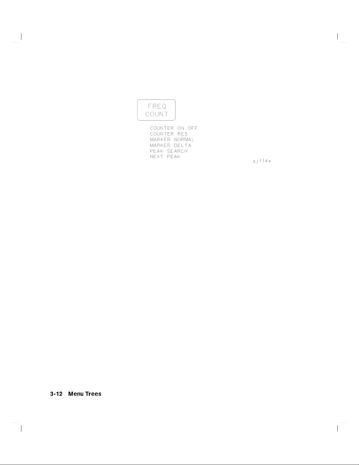
This chapter illustrates the dierent softkey menus available when pressing the
front-panel keys.
Menu Trees 3-1

* Becomes
y
Available only with internal mixing.
z
Not available for an 8563E/EC, 8564E/EC, or 8565E/EC.
x
Available only when
k
Not available for an 8560E/EC.
3-2 Menu Trees
NNNNNNNNNNNNNNNNNNNNNNNNNNNNNNNNNNN
NORM REF LVL
NNNNNNNNNNNNNNNNNNNNNNNNNNNNNNNNNNNNNNNNNNN
NORMLIZE ON OFF
NNNNNNNNNNNNNNNNNNNNNNNNNNNNNNNNNNNNNNNNNNN
when
NORMLIZE ON OFF
is set to ON.
is set to ON.

*Available only with internal mixing.
Menu Trees 3-3

3-4 Menu Trees

NNNNNNNNNNNNNNNNNNNNNNNNNNNNNNNNNNNNNNNNNNNNNNN
* The
N
TRACKING GENRATOR
menu shown here is for spectrum analyzers
without Option 002 installed. See AUX CTRL menu 3 of 3 for an 8560E/EC
with Option 002 installed.
NNNNNNNNNNNNNNNNNNNNNNNNNNNNNNNNNNNNNNNN
INTERNAL MIXER
an 8560E/EC without Option 002, only the INTERNAL MIXER softkey is
available (the softkeys accessed by
NNNNNNNNNNNNNNNNNNNNNNNNNNNNNNNNNNNNNNNN
EXTERNAL MIXER
is not shown for an 8560E with Option 002 installed. For
NNNNNNNNNNNNNNNNNNNNNNNNNNNNNNNNNNNNNNNN
INTERNAL MIXER
are not available).
is not shown for an 8560E with Option 002 installed and it
is non-functional for Option 327.
y
Signal identication functions are only available in non-preselected external
mixing mode, with rmware revisions920528, or with Option 008 installed.
NNNNNNNNNNNNNNNNNNNNNNNNNNNNNNNNNNN
z
This key changes to
MARKER DELTA
if the marker delta function is active.
NNNNNNNNNNNNNNNNNNNNNNNNNNNNNNNNNNNNN
x
This key changes to
k
This key is present only for the 8564E/EC and 8565E/EC.
V/GHz .25 .50
for the 8564E/EC and 8565E/EC.
Menu Trees 3-5

3-6 Menu Trees

* This key is not shown for an 8560E/EC with Option 002 installed and it is
non-functional for Option 327.
y
The signal identication function is only available in non-preselected external
mixing mode, with rmware revisions920528, or with Option 008 installed.
z
This key is displayed only if unpreselected external mixing is selected
NNNNNNNNNNNNNNNNNNNNNNNNNNNNNNNNNNNNNNNNNNNNNN
(
EXT MXR PRE UNPR
x
This key is displayed only if preselected external mixing is selected
NNNNNNNNNNNNNNNNNNNNNNNNNNNNNNNNNNNNNNNNNNNNNN
(
EXT MXR PRE UNPR
k
This key changes to
is set to
is set to
NNNNNNNNNNNNNNNNNNNNNNNNNNNNNNNNNN
N
MARKER DELTA
NNNNNNNNNNNNN
UNPR
).
NNNNNNNNNN
PRE
).
if the marker delta function is active.
Menu Trees 3-7

3-8 Menu Trees

* Changes to
y
Changes to
z
These functions are only available with rmware revisions>930809.
x
The CRT adjust pattern is used to help align the display of E-series
instruments.
NNNNNNNNNNNNNNNNNNNNNNNNNNNNNNNN
STOP ADJUST
NNNNNNNNNNNNNNNNNNNNNNNNNNNNNNNNNNNNN
STORE REF LVL
NNNNNNNNNNNNNNNNNNNNNNNNNNNNNNNN
if
FULL IF ADJ
NNNNNNNNNNNNNNNNNNNNNNNNNNNNNNNN
if
REF LVL ADJ
is pressed.
is pressed.
Menu Trees 3-9

* Changes to
y
Not available with Option 002 or Option 327.
z
Both E-series and EC-series instruments appear as E-series in the instrument
display when the DATECODE & OPTION key is pressed. EC-series
instruments also appear as Option 007 instrumen
option, which is standard in all EC-series instruments).
3-10 Menu Trees
NNNNNNNNNNNNNNNNNNNNNNNNNNNNNNNNNNNNNNNN
STORE GPIB ADR
if pressed.
ts(Option 007 is the FADC

* Changes to
instruments do not require adjustment; therefore the intensity adjustmentis
not active for 8560 EC-Series instruments.
y
Changes to
instruments do not require adjustment; therefore the focus is not activ
EC-Series instruments.
NNNNNNNNNNNNNNNNNNNNNNNNNNNNNNNNNNNNNNNN
STORE INTENSTY
NNNNNNNNNNNNNNNNNNNNNNNNNNNNNNNN
STORE FOCUS
NNNNNNNNNNNNNNNN
if
FOCUS
NNNNNNNNNNNNNNNNNNNNNNNN
if
INTENSTY
is pressed. Note: 8560 EC- Series
is pressed. Note: 8560 EC-Series
Menu Trees 3-11
e for
3-12 Menu Trees

NNNNNNNNNNNNNNNNNNNNNNNNNNNNNNNN
*
MORE 1 OF 2
is displayed under
with rmware revision 960401 and later.
4
FREQUENCY
5
only on sp ectrum analyzers
Menu Trees 3-13

3-14 Menu Trees

* Sp ectrum analyzers with rmware revisions930809 have fewer p ower and
adjacentchannel power (ACP) functions.
y
See the following gure for ACP setup menus.
NNNNNNNNNNNNN
z
The
SPAN
softkey is displayed if the markers are not active.
x
Present only when this menu is accessed from the occupied p ower menu.
Menu Trees 3-15

* The
y
z
3-16 Menu Trees
NNNNNNNNNNNNNNNNNNNNNNNN
ACP MENU
gure.
Available with rmware930809.
Available with rmware>931216.
softkey is under the
4
MEAS/USER
5
key. See the preceding

Menu Trees 3-17

*
4
MODULE
module is attached to the spectrum analyzer. See the 85620A documen
for more information ab out these softkeys.
y
4
MODULE
adjustment mo dule (TAM) is attached to the spectrum analyzer. See the
85629B documentation for more information about these softkeys. The
85629B is not compatible with the 8564E/EC or 8565E/EC
5
accesses these additional softkeys if the 85620A mass memory
5
accesses these additional softkeys if the 85629B test and
.
tation
Note
3-18 Menu Trees
The 8562E/TAM Interface Software is required when using the
TAM with the 8562E spectrum analyzer.

* Changes to
NNNNNNNNNNNNNNNNNNNNNNNNNNNNNNNNNNN
MARKER DELTA
NNNNNNNNNNNNNNNNNNNNNNNNNNNNNNNNNNNNN
MARKER NORMAL
is active.
if the spectrum analyzer is in zero span or
Menu Trees 3-19

*Available only with internal mixing above 2.9 GHz.
y
Available with preselected external mixing. Available with internal mixing
above 2.9 GHz.
3-20 Menu Trees

*Available with preselected external mixing. Available with internal mixing
above 2.9 GHz.
Menu Trees 3-21

* This softkey is blanked if
y
This softkey becomes
level (LVL).
3-22 Menu Trees
NNNNNNNNNNNNNNNNNNNNNNNNNNNNNNNNNNNNNNNNNNNNNNNN
GATE CTL EDGE LVL
NNNNNNNNNNNNNNNNNNNNNNNNNNNNNNNNNNNNNNNNNNN
LVL POL POS NEG
is set to level (LVL).
NNNNNNNNNNNNNNNNNNNNNNNNNNNNNNNNNNNNNNNNNNNNNNNN
if
GATE CTL EDGE LVL
is set to

Menu Trees 3-23


4
Front Panel Key Functions
This chapter lists the 8560 E-Series and 8560 EC-Series spectrum analyzer
front-panel functions. The table in front indicates the front panel key used to
nd each softkey.Ifyou know the front panel key,you can use the menu trees
to locate the key.
After the table, every front panel key and softkey is listed.
Next to eachkey lab el is a brief description of its operation.
For more detailed descriptions of the keys, refer to the
Agilent Technologies 8560 E-Series and EC-Series Spectrum Analyzers User's
Guide
.
Front Panel Key Functions 4-1

Finding the Front Panel Key
Table 4-1. Front Panel Softkey Access
Softkey FrontPanel Access
NNNNNNNNNNNNNNNNNNNNNNNNNNNNNNNNNNNNNNNN
1MARKER OCC BW
4
MEAS/USER
NNNNNNNNNNNNNNNNNNNNNNNNNNNNNNNNNNNNNNNN
# ALT CHANNELS
4
MEAS/USER
NNNNNNNNNNNNNNNNNNNNNNNNNNNNNNNNNNNNN
0!10V LO SWP
4
AUX CTRL
NNNNNNNNNNNNNNNNNNNNNNNNNNNNNNNNNNNNNNNN
.5 V/GHz (FAV)
4
AUX CTRL
NNNNNNNNNNNNNNNNNNNNNNNNNNNNNNNNNNNNN
10MHz EXT INT
4
AUX CTRL
NNNNNNNNNNNNNNNNNNNNNNNNNNNNN
2BW METHOD
4
MEAS/USER
NNNNNNNNNNNNNNNNNNNNNNNNNNNNN
3dB POINTS
4
MEAS/USER
NNNNNNNNNNNNNNNNNNNNNNNNNNNNN
6dB POINTS
4
MEAS/USER
NNNNNNNNNNNNNNNNNN
A+B!A
4
TRACE
NNNNNNNNNNNNNNNNNNNNNNNNNNNNNNNNNNNNN
A-B!A ON OFF
NNNNNNNNNNNNNNNNNNNNNNNNNNNNNNNNNNNNNNNNNNNN
N
A-B+DL!A ON OFF
4
TRACE
4
TRACE
NNNNNNNNNNNNNNNNNNNNNNNN
A EXCH B
NNNNNNNNNNNNNNNNNNNNNNN
N
ACCELRAT
4
TRACE
4
MEAS/USER
NNNNNNNNNNNNNNNNNNNNNNNNNNNNNNNNNNNNNNNNNNN
ACCELRAT FASTER
NNNNNNNNNNNNNNNNNNNNNNNNNNNNNNNNNNNNNNNNNNNNN
N
ACCELRAT FASTEST
4
MEAS/USER
4
MEAS/USER
NNNNNNNNNNNNNNNNNNNNNNNNNNNNNNNNNNNNNNNNNNN
ACCELRAT NORMAL
4
MEAS/USER
NNNNNNNNNNNNNNNNNNNNNNNNNNNNNNNNNNNNNNNNNNNNNN
ACP AUTO MEASURE
4
MEAS/USER
NNNNNNNNNNNNNNNNNNNNNNNNNNNNNNNN
ACP COMPUTE
4
MEAS/USER
NNNNNNNNNNNNNNNNNNNNNNNN
ACP MENU
4
MEAS/USER
NNNNNNNNNNNNNNNNNNNNNNNNNN
ACP SETUP
4
MEAS/USER
5
5
5
5
5
5
5
5
5
5
5
5
5
5
5
5
5
5
5
5
4-2 Front Panel Key Functions

Table 4-1. Front Panel Softkey Access (continued)
Softkey FrontPanel Access
NNNNNNNNNNNNNNNNNNNNNNNNNNNNNNNNNNNNNNNNNNN
ACPGRAPH ON OFF
NNNNNNNNNNNNNNNNNNNNNNNNNNNNNNNNNNNNNNNNNNNNNNNN
ACPSTATE DFL CURR
NNNNNNNNNNNNNNNNNNNNNNNNNNNNNNNNNNNNNNNNNNNNNNNN
ADJ CURR IF STATE
NNNNNNNNNNNNNNNNNNNNNNNNNNNNN
AGC ON OFF
NNNNNNNNNNNNNNNNNNNNNNNNNNNNNNNN
ALC INT EXT
NNNNNNNNNN
ALL
NNNNNNNNNNNNNNNNNNNNNNNNNNNNNNNN
AMPCOR MENU
NNNNNNNNNNNNNNNNNNNNNNNNNNNNNNNNNNNNN
AMPCOR ON OFF
NNNNNNNNNNNNNNNNNNNNNNNNNNNNNNNNNNNNN
ANALOG METHOD
NNNNNNNNNNNNNNNNNNNNNNNNNNNNN
ANNOT HELP
NNNNNNNNNNNNNNNNNNNNNNNNNNNNNNNNNNN
ANNOT ON OFF
NNNNNNNNNNNNNNNNNNNNNNNNNNNNNNNNNNNNNNNNNNN
AM DEMOD ON OFF
NNNNNNNNNNNNNNNNNNNNNNNNNNNNNNNN
AM/FM DEMOD
NNNNNNNNNNNNNNNNNNNNNNNNNNNNNNNNNNNNN
AMPTD CORRECT
NNNNNNNNNNNNNNNNNNNNNNNNNNNNNNNN
AMPTD UNITS
NNNNNNNNNNNNNNNNNNNNNNNNNNNNNNNNNNNNNNNNNNNNNN
ANALYZER ADDRESS
NNNNNNNNNNNNNNNNNNNNNNNNNNNNNNNNNNNNNNNN
ATTEN AUTO MAN
NNNNNNNNNNNNNNNNNNNNNNNNNNNNNNNNNNNNNNNNNNNNNN
AVERAGE CNV LOSS
NNNNNNNNNNNNNNNNNNNNNNNNNNNNNNNNNNNNNNNNNNN
AVG "OFF" POWER
NNNNNNNNNNNNNNNNNNNNNNNNNNNNNNNNNNNNNNNN
AVG "ON" POWER
4
MEAS/USER
4
MEAS/USER
4
5
CAL
4
AUX CTRL
4
AUX CTRL
4
AUTO COUPLE
4
CAL
4
CAL
4
MEAS/USER
4
DISPLAY
4
DISPLAY
4
AUX CTRL
4
AUX CTRL
4
AUX CTRL
4
AMPLITUDE
4
CONFIG
4
AMPLITUDE
4
AUX CTRL
4
MEAS/USER
4
MEAS/USER
5
5
5
5
5
5
5
5
5
5
5
5
5
5
5
5
5,4
AUTO COUPLE
5
5
5
Front Panel Key Functions 4-3

Table 4-1. Front Panel Softkey Access (continued)
Softkey FrontPanel Access
NNNNNNNNNNNNNNNNNNNNN
B-DL!B
NNNNNNNNNNNNNNNN
B&W
NNNNNNNNNNNNNNNNNNNNNNNNNNNNN
BACK SPACE
NNNNNNNNNNNNN
BIAS
NNNNNNNNNNNNNNNNNNNNNNNN
BIAS OFF
NNNNNNNNNNNNNNNNNNNNN
BLANK A
NNNNNNNNNNNNNNNNNNNNN
BLANK B
NNNNNNNNNNNNNNNNNNNNNNNNNNNNNNNNNNNNNNNN
BURST/WEIGHTNG
NNNNNNNNNNNNNNNNNNNNNNNNNNNNNNNN
BURST WIDTH
NNNNNNNNNNNNNNNNNNNNNNNNNNNNNNNNNNN
BURST PERIOD
NNNNNNNNNNNNNNNNNNNNNNNNNNNNNNNNNNNNNNNNNNN
BURSTPWR METHOD
NNNNNNNNNNNNNNNNNNNNNNNNNNNNNNNNNNN
CAL OPN/SHRT
NNNNNNNNNNNNNNNNNNNNNNNN
CAL THRU
NNNNNNNNNNNNNNNNNNNNNNNNNNNNNNNNNNNNNNNNNNNNNN
CARRIER PWR MENU
NNNNNNNNNNNNNNNNNNNNNNNNNNNNNNNN
CENTER FREQ
NNNNNNNNNNNNNNNNNNNNNNN
CF/2!CF
NNNNNNNNNNNNNNNNNNNNNNN
CF*2!CF
NNNNNNNNNNNNNNNNNNNNNNNNNNNNNNNNNNNNNNNNNNNNNN
CF STEP AUTO MAN
NNNNNNNNNNNNNNNNNNNNNNNNNNNNNNNNNNNNNNNN
CH EDGES!1MKR
NNNNNNNNNNNNNNNNNNNNNNNNNNNNNNNNNNNNNNNNNNNNN
CH SPACG
!
1MKR
4
5
TRACE
4
CONFIG
4
DISPLAY
4
AUX CTRL
4
AUX CTRL
4
TRACE
4
TRACE
4
MEAS/USER
4
MEAS/USER
4
MEAS/USER
4
MEAS/USER
4
AUX CTRL
4
AUX CTRL
4
MEAS/USER
4
FREQUENCY
4
FREQUENCY
4
FREQUENCY
4
AUTO COUPLE
4
MEAS/USER
4
MEAS/USER
5
5
5
5
5
5
5
5
5
5
5
5
5
5
5
5
5,4
5
5
FREQUENCY
5
4-4 Front Panel Key Functions

Table 4-1. Front Panel Softkey Access (continued)
Softkey FrontPanel Access
NNNNNNNNNNNNNNNNNNNNNNNNNNNNNNNNNNN
CHAN DN <<<<
NNNNNNNNNNNNNNNNNNNNNNNNNNNNNNNNNNNNNNNNNNNNNN
CHAN PWR OVER BW
NNNNNNNNNNNNNNNNNNNNNNNNNNNNNNNNNNN
CHAN UP >>>>
NNNNNNNNNNNNNNNNNNNNNNNNNNNNNNNNNNNNNNNNNNNNNN
CHANNEL BANDWDTH
NNNNNNNNNNNNNNNNNNNNNNNNNNNNNNNNNNNNNNNNNNNNNN
CHANNEL PWR MENU
NNNNNNNNNNNNNNNNNNNNNNNNNNNNNNNNNNNNNNNNNNN
CHANNEL SPACING
NNNNNNNNNNNNNNNNNNNNNNNNNNNNNNNNNNNNN
CHAR SET 1 2
NNNNNNNNNNNNNNNNNNNNNNNNNNNNNNNNNNNNNNNNNNN
CHPWR BW [ ]
NNNNNNNNNNNNNNNNNNNNNNNNNNNNNNNNNNNNN
CLEAR WRITE A
NNNNNNNNNNNNNNNNNNNNNNNNNNNNNNNNNNNNN
CLEAR WRITE B
NNNNNNNNNNNNNNNNNNNNNNNNNNNNNNNNNNNNNNNNNNNNNN
CNV LOSS VS FREQ
NNNNNNNNNNNNNNNN
COLOR
NNNNNNNNNNNNNNNNNNNNNNNNNNNNNNNNNNN
CONT MEASURE
NNNNNNNNNNNNNNNNNNNNNNNNNNNNNNNNNNNNNNNNNNNNNNNN
COPY DEV PRNT PLT
NNNNNNNNNNNNNNNNNNNNNNNNNNNNNNNNNNNNNNNN
COUNTER ON OFF
NNNNNNNNNNNNNNNNNNNNNNNNNNNNNNNN
COUNTER RES
NNNNNNNNNNNNNNNNNNNNNNNNNNNNNNNNNNNNNNNN
COUPLING AC DC
NNNNNNNNNNNNNNNNNNNNNNNNNNNNNNNNNNNNNNNNNNN
CRT ADJ PATTERN
4
MEAS/USER
4
MEAS/USER
4
MEAS/USER
4
MEAS/USER
4
MEAS/USER
4
MEAS/USER
4
DISPLAY
4
MEAS/USER
4
TRACE
4
TRACE
4
AUX CTRL
4
CONFIG
4
MEAS/USER
4
CONFIG
4
FREQ COUNT
4
FREQ COUNT
4
AMPLITUDE
4
CAL
5
5
5
5
5
5
5
5
5
5
5
5
5
5
5
5
5
5
Front Panel Key Functions 4-5

Table 4-1. Front Panel Softkey Access (continued)
Softkey FrontPanel Access
NNNNNNNNNNNNNNNNNNNNNNNNNNNNNNNNNNNNNNNNNNNNNNNN
DATECODE &OPTIONS
NNNNNNNNNN
dBm
NNNNNNNNNNNNN
dBV
NNNNNNNNNNNNN
dBmV
NNNNNNNNNNNNNNNNNNNNNNNNNNNNNNNNNNNNNNNN
DELETE CORR PT
NNNNNNNNNNNNNNNNNNNNNNNNNNNNN
DEMOD TIME
NNNNNNNNNNNNNNNNNNNNNNNNNNNNNNNNNNNNNNNN
DETECTOR MODES
NNNNNNNNNNNNNNNNNNNNNNNNNNNNNNNNNNNNNNNNNNNNNNNN
DETECTOR NEG PEAK
NNNNNNNNNNNNNNNNNNNNNNNNNNNNNNNNNNNNNNNNNNN
DETECTOR NORMAL
NNNNNNNNNNNNNNNNNNNNNNNNNNNNNNNNNNNNNNNNNNNNNNNN
DETECTOR POS PEAK
NNNNNNNNNNNNNNNNNNNNNNNNNNNNNNNNNNNNNNNNNNN
DETECTOR SAMPLE
NNNNNNNNNNNNNNNNNNNNNNNNNNNNNNNNNNNNNNNN
DLY SWP [ ]
NNNNNNNNNNNNNNNNNNNNNNNNNNNNNNNNNNNNNNNN
DLY SWP ON OFF
NNNNNNNNNNNNNNNNNNNNNNNNNN
DONE EDIT
NNNNNNNNNNNNNNNNNNNNNNNNNNNNNNNNNNNNNNNNNNN
DSPL LIN ON OFF
NNNNNNNNNNNNNNNNNNNNNNNNNNNNNNNNNNNNNNNNNNNNNN
EDGE POL POS NEG
NNNNNNNNNNNNNNNNNNNNNNNNNNNNNNNN
EDIT AMPCOR
NNNNNNNNNNNNNNNNNNNNNNNNNN
EDIT AMPL
NNNNNNNNNNNNNNNNNNNNNNNNNN
EDIT FREQ
NNNNNNNNNNNNNNNNNNNNNNNNNNNNNNNNNNN
ELAPSED TIME
NNNNNNNNNNNNNNNNNNNNNNNNNNNNNNNN
ERASE TITLE
4
CONFIG
4
AMPLITUDE
4
AMPLITUDE
4
AMPLITUDE
4
CAL
4
AUX CTRL
4
TRACE
4
TRACE
4
TRACE
4
TRACE
4
TRACE
4
SWEEP
4
SWEEP
4
CAL
4
DISPLAY
4
SWEEP
4
CAL
4
CAL
4
CAL
4
RECALL
4
DISPLAY
5
5
5
5
5
5
5
5
5
5
5
5
5
5
5
5
5
5
5
5
5
4-6 Front Panel Key Functions

Table 4-1. Front Panel Softkey Access (continued)
Softkey FrontPanel Access
NNNNNNNNNNNNNNNNNNNNNNNNNNNNNNNNNNNNNNNN
EXIT & RESTORE
NNNNNNNNNNNNNNNNNNNNNNNN
EXIT ACP
NNNNNNNNNNNNNNNNNNNNNNNNNNNNNNNN
EXIT AMPCOR
NNNNNNNNNNNNNNNNNNNNNNNNNNNNNNNNNNNNNNNNNNNNNN
EXT MXR PRE UNPR
NNNNNNNNNNNNNNNNNNNNNNNN
EXTERNAL
NNNNNNNNNNNNNNNNNNNNNNNNNNNNNNNNNNNNNNNN
EXTERNAL MIXER
NNNNNNNNNNNNNNNNNNNNNNNNNNNNNNNNNNNNNNNNNNNNNN
FACTORY PRSEL PK
NNNNNNNNNNNNNNNNNNNNNNNN
FFT MEAS
NNNNNNNNNNNNNNNNNNNNNNNNNNNNNNNNNNNNNNNNNNN
FM DEMOD ON OFF
NNNNNNNNNNNNNNNN
FOCUS
NNNNNNNNNNNNNNNNNNNNNNNNNNNNNNNN
FRAC N FREQ
NNNNNNNNNNNNNNNNNNNNNNNN
FREE RUN
NNNNNNNNNNNNNNNNNNNNNNNNNNNNNNNNNNNNN
FREQ DIAGNOSE
NNNNNNNNNNNNNNNNNNNNNNNNNNNNNNNNNNN
FREQ DSP OFF
NNNNNNNNNNNNNNNNNNNNNNNNNNNNNNNN
FREQ OFFSET
NNNNNNNNNNNNNNNNNNNNNNNNNN
FULL BAND
NNNNNNNNNNNNNNNNNNNNNNNNNNNNNNNN
FULL IF ADJ
NNNNNNNNNNNNNNNNNNNNNNNNNN
FULL SPAN
NNNNNNNNNNNNNNNNNNNNNNNNNNNNNNNNNNNNNNNNNNNNNNNN
GATE CTL EDGE LVL
NNNNNNNNNNNNNNNNNNNNNNNNNNNNNNNNNNNNNNNNNNN
GATE DLY [ ]
NNNNNNNNNNNNNNNNNNNNNNNNNNNNNNNNNNNNNNNNNNN
GATE LEN [ ]
NNNNNNNNNNNNNNNNNNNNNNNNNNNNNNNN
GATE ON OFF
4
MEAS/USER
4
MEAS/USER
4
5
CAL
4
4
4
4
4
4
4
4
4
4
4
4
4
4
4
4
4
4
4
5
CONFIG
5
TRIG
AUX CTRL
AUX CTRL
MEAS/USER
AUX CTRL
DISPLAY
CAL
TRIG
CAL
DISPLAY
5
5
5
5
5
FREQUENCY
AUX CTRL
5
CAL
5
SPAN
5
SWEEP
5
SWEEP
5
SWEEP
5
SWEEP
5
5
5
5
5
5
5
5
Front Panel Key Functions 4-7

Table 4-1. Front Panel Softkey Access (continued)
Softkey FrontPanel Access
NNNNNNNNNNNNNNNNNNNNNNNNNNNNNNNNNNN
GATED METHOD
NNNNNNNNNNNNNNNNNNNNNNNNNNNNNNNN
GATED VIDEO
NNNNNNNNNNNNNNNNNNNNNNNNNNNNNNNN
GRAT ON OFF
NNNNNNNNNNNNNNNNNNNNNNNNNNNNNNNNNNNNN
IF ADJ ON OFF
NNNNNNNNNNNNNNNNNNNNNNNN
INTENSTY
NNNNNNNNNNNNNNNNNNNNNNNNNNNNNNNNNNNNNNNN
INTERNAL MIXER
NNNNNNNNNNNNNNNNNNNNNNNNNN
LAST SPAN
NNNNNNNNNNNNNNNNNNNNNNNNNNNNN
LAST STATE
NNNNNNNNNNNNN
LINE
NNNNNNNNNNNNNNNNNN
LINEAR
NNNNNNNNNNNNNNNNNNNNN
LO FREQ
NNNNNNNNNNNNNNNNNNNNNNNNNNNNNNNNNNNNN
LOCK HARMONIC
NNNNNNNNNNNNNNNNNNNNNNNNNNNNNNNN
LOCK ON OFF
NNNNNNNNNNNNNNNNNNNNNNNNNNNNN
LOG dB/DIV
NNNNNNNNNNNNNNNNNNNNNNNNNNNNNNNNNNNNNNNNNNN
LVL POL POS NEG
NNNNNNNNNNNNNNNNNNNNNNNNNNNNNNNN
MAN TRK ADJ
NNNNNNNNNNNNNNNNNNNNNNNNNNNNNNNNNN
MARKER
!
CF
NNNNNNNNNNNNNNNNNNNNNNNNNNNNNNNNNNNNNNNNNNNNNNNN
MARKER
!
CF STEP
NNNNNNNNNNNNNNNNNNNNNNNNNNNNNNNNNNNNNNNNNNNNNNNN
MARKER
!
REF LVL
4
MEAS/USER
4
4
4
4
4
4
4
4
4
4
4
4
4
4
4
4
4
4
5
SWEEP
DISPLAY
CAL
DISPLAY
5
5
5
AUX CTRL
5
SPAN
PRESET
TRIG
5,4
5
AMPLITUDE
5
CAL
AUX CTRL
AUX CTRL
AMPLITUDE
5
SWEEP
AUX CTRL
5,4
MKR
!
5
MKR
!
5
MKR
!
5
5
RECALL
5
5
5
5
5
5
PEAK SEARCH
5
4-8 Front Panel Key Functions

Table 4-1. Front Panel Softkey Access (continued)
Softkey FrontPanel Access
NNNNNNNNNNNNNNNNNNNNNNNNNNNNNNNNNNNNNNNN
MARKER 1/DELTA
NNNNNNNNNNNNNNNNNNNNNNNNNNNNNNNNNNN
MARKER DELTA
NNNNNNNNNNNNNNNNNNNNNNNNNNNNNNNNNNNNN
MARKER NORMAL
NNNNNNNNNNNNNNNNNNNNNNNNNNNNNNNN
MARKERS OFF
NNNNNNNNNNNNNNNNNNNNNNNNNNNNN
MAX HOLD A
NNNNNNNNNNNNNNNNNNNNNNNNNNNNN
MAX HOLD B
NNNNNNNNNNNNNNNNNNNNNNNNNNNNNNNNNNNNN
MAX MXR LEVEL
NNNNNNNNNNNNNNNNNNNNN
METHODS
NNNNNNNNNNNNNNNNNNNNNNNNNNNNNNNN
MKR 1
!
CF
NNNNNNNNNNNNNNNNNNNNNNNNNNNNNNNNNNNNNNNNNNNNN
MKR 1
!
CF STEP
NNNNNNNNNNNNNNNNNNNNNNNNNNNNNNNNNNNNNNNNNNNNNNNN
MKR 1
!
CHPWR BW
NNNNNNNNNNNNNNNNNNNNNNNNNNNNNNNNNNNNN
MKR 1
!
SPAN
NNNNNNNNNNNNNNNNNNNNNNNNNNNNNNNNNNNNN
MKR 1/1
!
CF
NNNNNNNNNNNNNNNNNNNNNNNNNNNNNNNNNNNNNNNNNNNNNNNNNNN
MKR 1/1
!
CF STEP
NNNNNNNNNNNNNNNNNNNNNNNNNNNNNNNNNNNNNNNN
MKR MEAN
!
CF
NNNNNNNNNNNNNNNNNNNNNNNNNNNNNNNNNNNNNNNNNNN
MKRNOISE ON OFF
NNNNNNNNNNNNNNNNNNNNNNNNNNNNNNNNNNNNN
NEGATIVE BIAS
NNNNNNNNNNNNNNNNNNNNNNNNNNNNNNNN
NEW CORR PT
4
5
MKR
4
FREQ COUNT
4
AUX CTRL
4
AUX CTRL
4
MKR
4
TRACE
4
TRACE
4
AMPLITUDE
4
MEAS/USER
4
MKR
4
MKR
4
MEAS/USER
4
MKR
4
MKR
4
MKR
4
MEAS/USER
4
MKR
4
AUX CTRL
4
CAL
5
5,4
5
5
5
5
!
5
!
5
!
5
!
5
!
5
5
5
5,4
MKR
5,4
FREQ COUNT
5
5
5
5
PEAK SEARCH
5,4
MKR
5,4
5
CAL
,
5
Front Panel Key Functions 4-9
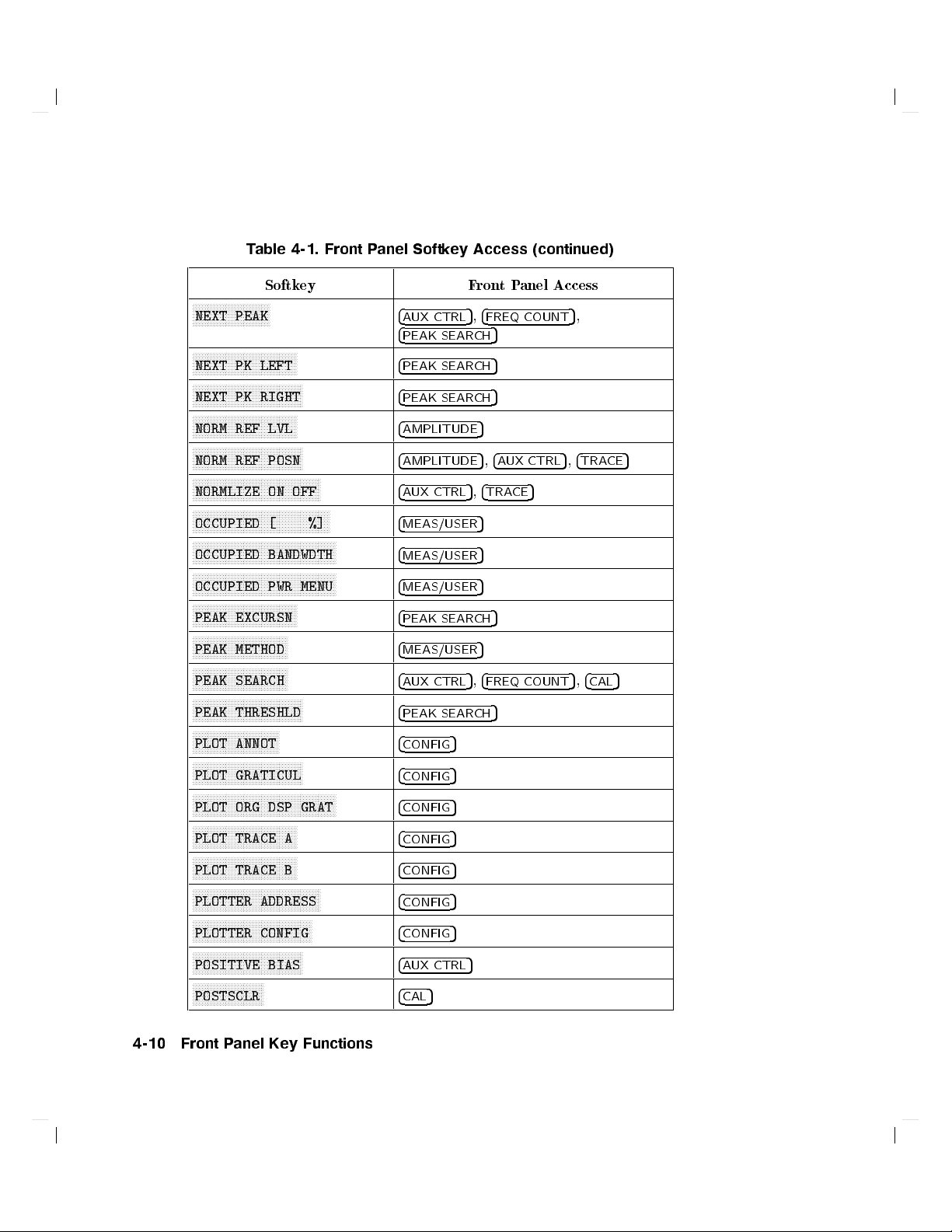
Table 4-1. Front Panel Softkey Access (continued)
Softkey FrontPanel Access
NNNNNNNNNNNNNNNNNNNNNNNNNN
NEXT PEAK
NNNNNNNNNNNNNNNNNNNNNNNNNNNNNNNNNNN
NEXT PK LEFT
NNNNNNNNNNNNNNNNNNNNNNNNNNNNNNNNNNNNN
NEXT PK RIGHT
NNNNNNNNNNNNNNNNNNNNNNNNNNNNNNNNNNN
NORM REF LVL
NNNNNNNNNNNNNNNNNNNNNNNNNNNNNNNNNNNNN
NORM REF POSN
NNNNNNNNNNNNNNNNNNNNNNNNNNNNNNNNNNNNNNNNNNN
NORMLIZE ON OFF
NNNNNNNNNNNNNNNNNNNNNNNNNNNNNNNNNNNNNNNNNNNNNN
OCCUPIED [ %]
NNNNNNNNNNNNNNNNNNNNNNNNNNNNNNNNNNNNNNNNNNNNNNNN
OCCUPIED BANDWDTH
NNNNNNNNNNNNNNNNNNNNNNNNNNNNNNNNNNNNNNNNNNNNNNNN
OCCUPIED PWR MENU
NNNNNNNNNNNNNNNNNNNNNNNNNNNNNNNNNNN
PEAK EXCURSN
NNNNNNNNNNNNNNNNNNNNNNNNNNNNNNNN
PEAK METHOD
NNNNNNNNNNNNNNNNNNNNNNNNNNNNNNNN
PEAK SEARCH
NNNNNNNNNNNNNNNNNNNNNNNNNNNNNNNNNNNNN
PEAK THRESHLD
NNNNNNNNNNNNNNNNNNNNNNNNNNNNN
PLOT ANNOT
NNNNNNNNNNNNNNNNNNNNNNNNNNNNNNNNNNNNN
PLOT GRATICUL
NNNNNNNNNNNNNNNNNNNNNNNNNNNNNNNNNNNNNNNNNNNNNNNN
PLOT ORG DSP GRAT
NNNNNNNNNNNNNNNNNNNNNNNNNNNNNNNNNNN
PLOT TRACE A
NNNNNNNNNNNNNNNNNNNNNNNNNNNNNNNNNNN
PLOT TRACE B
NNNNNNNNNNNNNNNNNNNNNNNNNNNNNNNNNNNNNNNNNNN
PLOTTER ADDRESS
NNNNNNNNNNNNNNNNNNNNNNNNNNNNNNNNNNNNNNNN
PLOTTER CONFIG
NNNNNNNNNNNNNNNNNNNNNNNNNNNNNNNNNNNNN
POSITIVE BIAS
NNNNNNNNNNNNNNNNNNNNNNNN
POSTSCLR
4
AUX CTRL
4
PEAK SEARCH
4
PEAK SEARCH
4
PEAK SEARCH
4
AMPLITUDE
4
AMPLITUDE
4
AUX CTRL
4
MEAS/USER
4
MEAS/USER
4
MEAS/USER
4
PEAK SEARCH
4
MEAS/USER
4
AUX CTRL
4
PEAK SEARCH
4
CONFIG
4
CONFIG
4
CONFIG
4
CONFIG
4
CONFIG
4
CONFIG
4
CONFIG
4
AUX CTRL
4
CAL
5,4
5,4
5,4
5
5
5
5
5
5
5
5
5
FREQ COUNT
5
5
5
5
5,4
AUX CTRL
5
TRACE
5
5
5
5
5
FREQ COUNT
5
5
5,4
5,4
,
TRACE
CAL
5
5
4-10 Front Panel Key Functions

Table 4-1. Front Panel Softkey Access (continued)
Softkey FrontPanel Access
NNNNNNNNNNNNNNNNNNNNNNNNNNNNN
POWER MENU
NNNNNNNNNNNNNNNNNNNNNNNN
POWER ON
NNNNNNNNNNNNNNNNNNNNNNNNNNNNNNNNNNNNNNNN
PRESEL AUTO PK
NNNNNNNNNNNNNNNNNNNNNNNNNNNNNNNNNNNNNNNN
PRESEL MAN ADJ
NNNNNNNNNNNNNNNNNNNNNNNNNNNNNNNN
PRESEL PEAK
NNNNNNNNNNNNNNNNNNNNNNNNNNNNNNNNNNNNNNNNNNN
PRINTER ADDRESS
NNNNNNNNNNNNNNNNNNNNNNNNNNNNNNNNNNNNNNNN
PRINTER CONFIG
NNNNNNNNNNNNNNNNNNNNNNNNNNNNN
PURGE CORR
NNNNNNNNNNNNNNNNNNNNNNNNNNNNNNNNNNN
PWR ON STATE
NNNNNNNNNNNNNNNNNNNNNNNNNNNNNNNNNNNNN
PWR MENU HELP
NNNNNNNNNNNNNNNNNNNNNNNNNNNNNNNNNNNNNNNN
PWR SWP ON OFF
NNNNNNNNNNNNNNNNNNNNNNNNNN
RANGE LVL
NNNNNNNNNNNNNNNNNNNNNNNNNNNNNNNNNNN
RAW OSC FREQ
NNNNNNNNNNNNNNNNNNNNNNNNNNNNNNNNNNNNNNNN
RBW/SPAN RATIO
NNNNNNNNNNNNNNNNNNNNNNNNNNNNNNNNNNNNNNNNNNN
REALIGN LO & IF
NNNNNNNNNNNNNNNNNNNNNNNNNNNNN
REAR PANEL
NNNNNNNNNNNNNNNNNNNNNNNNNNNNNNNNNNNNN
RECALL AMPCOR
NNNNNNNNNNNNNNNNNNNNNNNNNNNNNNNNNNNNN
RECALL ERRORS
NNNNNNNNNNNNNNNNNNNNNNNNNNNNNNNNNNNNNNNNNNN
RECALL OPN/SHRT
NNNNNNNNNNNNNNNNNNNNNNNNNNNNNNNNNNNNNNNNNNN
RECALL PRSEL PK
4
MEAS/USER
4
RECALL
4
AMPLITUDE
4
AMPLITUDE
4
AUX CTRL
4
CONFIG
4
CONFIG
4
CAL
4
SAVE
4
MEAS/USER
4
AUX CTRL
4
AMPLITUDE
4
CAL
5
5
5
5
5
5
4BW5
4
5
CAL
4
AUX CTRL
4
5
CAL
4
RECALL
4
AUX CTRL
4
RECALL
5
5
5
5,4
5,4
5
5
5
5,4
5
5
AUX CTRL
AUX CTRL
AUX CTRL
5
5
5
Front Panel Key Functions 4-11

Table 4-1. Front Panel Softkey Access (continued)
Softkey FrontPanel Access
NNNNNNNNNNNNNNNNNNNNNNNNNNNNNNNNNNN
RECALL STATE
NNNNNNNNNNNNNNNNNNNNNNNNNNNNNNNN
RECALL THRU
NNNNNNNNNNNNNNNNNNNNNNNNNNNNNNNNNNNNNNNN
RECALL TO TR A
NNNNNNNNNNNNNNNNNNNNNNNNNNNNNNNNNNNNNNNN
RECALL TO TR B
NNNNNNNNNNNNNNNNNNNNN
REF LVL
NNNNNNNNNNNNNNNNNNNNNNNNNNNNNNNN
REF LVL ADJ
NNNNNNNNNNNNNNNNNNNNNNNNNNNNNNNNNNNNNNNN
REF LVL OFFSET
NNNNNNNNNNNNNNNNNNNNNNNNNNNNNNNNNNNNNNNNNNN
RES BW AUTO MAN
NNNNNNNNNNNNNNNNNNNNNNNNNNNNNNNNNNN
SAMPLER FREQ
NNNNNNNNNNNNNNNNNNNNNNNNNNNNNNNNNNNNNNNNNNNNNN
SAMPLER HARMONIC
NNNNNNNNNNNNNNNNNNNNNNNNNNNNNNNN
SAVE AMPCOR
NNNNNNNNNNNNNNNNNNNNNNNNNNNNNNNNNNNNN
SAVE PRSEL PK
NNNNNNNNNNNNNNNNNNNNNNNNNNNNN
SAVE STATE
NNNNNNNNNNNNNNNNNNNNNNNNNNNNNNNNNNN
SAVE TRACE A
NNNNNNNNNNNNNNNNNNNNNNNNNNNNNNNNNNN
SAVE TRACE B
NNNNNNNNNNNNNNNNNNNNNNNNNNNNNNNNNNNNNNNNNNN
SAVELOCK ON OFF
NNNNNNNNNNNNNNNNNNNNNNNNNNNNNNNNNNN
SCREEN TITLE
NNNNNNNNNNNNNNNNNNNNNNNNNNNNNNNNNNNNNNNNNNN
SCROLL CORR PTS
NNNNNNNNNNNNNNNNNNNNNNNNNNNNNNNN
SELECT CHAR
4
RECALL
4
AUX CTRL
4
RECALL
4
RECALL
4
AMPLITUDE
4
CAL
4
AMPLITUDE
4
AUTO COUPLE
4
CAL
4
CAL
4
CAL
4
SAVE
4
SAVE
4
SAVE
4
SAVE
4
SAVE
4
DISPLAY
4
CAL
4
DISPLAY
5
5
5
5
5
5
5
5
5
5
5
5
5
5
5
5
5
5
5,4
5
BW
4-12 Front Panel Key Functions

Table 4-1. Front Panel Softkey Access (continued)
Softkey FrontPanel Access
NNNNNNNNNNNNNNNNNNNNNNNNNNNNNNNNNN
SIG ID
!
CF
NNNNNNNNNNNNNNNNNNNNNNNNNNNNNNNNNNNNN
SIG ID AT MKR
NNNNNNNNNNNNNNNNNNNNNNNNNNNNNNNNNNNNN
SIG ID ON OFF
NNNNNNNNNNNNNNNNNNNNNNNNNNNNNNNNNNNNNNNN
SIG TRK ON OFF
NNNNNNNNNNNNNNNNNNNNNNNNNNNNNNNNNNN
SIGNAL IDENT
NNNNNNNNNNNNNNNNNNNNNNNNNNNNNNNNNNNNNNNN
SINGLE MEASURE
NNNNNNNNNNNNNNNNNNNNNNNNNN
SOFTKEY 1
thru
NNNNNNNNNNNNNNNNNNNNNNNNNN
SOFTKEY 5
NNNNNNNNNNNNNNNNNNNNNNNNNNNNNNNNNNNNNNNNNNN
SOURCE CAL MENU
NNNNNNNNNNNNNNNN
SPACE
NNNNNNNNNNNNNNNNNNNNNNNNNNNNNNNNNNNNNNNNNNNNNN
SPACING/BANDWDTH
NNNNNNNNNNNNN
SPAN
NNNNNNNNNNNNNNNNNNNNNNNNNN
SPAN ZOOM
NNNNNNNNNNNNNNNNNNNNNNNNNNNNNNNNNNNNNNNN
SQUELCH ON OFF
NNNNNNNNNNNNNNNNNNNNNNNNNNNNNNNNNNNNNNNN
SRC PWR OFFSET
NNNNNNNNNNNNNNNNNNNNNNNNNNNNNNNNNNNNNNNN
SRC PWR ON OFF
NNNNNNNNNNNNNNNNNNNNNNNNNNNNNNNNNNNNNNNNNNNNNN
SRC PWR STP SIZE
NNNNNNNNNNNNNNNNNNNNNNNNNNNNN
START FREQ
NNNNNNNNNNNNNNNNNNNNN
STATE 0
thru
NNNNNNNNNNNNNNNNNNNNN
STATE 9
NNNNNNNNNNNNNNNNNNNNNNNNNN
STOP FREQ
NNNNNNNNNNNNNNNNNNNNNNNNNNNNNNNNNNNNNNNN
SWEEP CONT SGL
NNNNNNNNNNNNNNNNNNNNNNNNNNNNNNNNNNNNN
SWP CPL SR SA
NNNNNNNNNNNNNNNNNNNNNNNNNNNNNNNNNNNNNNNNNNNNNNNN
SWP TIME AUTO MAN
4
AUX CTRL
4
AUX CTRL
4
AUX CTRL
4
MKR
4
AUX CTRL
4
MEAS/USER
4
CAL
4
AUX CTRL
4
DISPLAY
4
MEAS/USER
4
SPAN
4
SPAN
4
AUX CTRL
4
AUX CTRL
4
AUX CTRL
4
AUX CTRL
4
FREQUENCY
4
RECALL
4
FREQUENCY
4
SWEEP
4
AUX CTRL
4
AUTO COUPLE
5
5
5
5
5
5
5
5
5
5
5
5
5
5
5,4
SAVE
5,4
TRIG
5
5
5
5
5
5
5
5,4
SWEEP
5
Front Panel Key Functions 4-13

Table 4-1. Front Panel Softkey Access (continued)
Softkey FrontPanel Access
NNNNNNNNNNNNNNNNNNNNNNNNNNNNNNNNNNNNNNNNNNN
THRESHLD ON OFF
NNNNNNNNNNNNNNNNNNNNNNNNNNNNN
TITLE DONE
NNNNNNNNNNNNNNNNNNNNN
TRACE 0
thru
NNNNNNNNNNNNNNNNNNNNN
TRACE 7
NNNNNNNNNNNNNNNNNNNNNNNNNNNNN
TRACE A B
NNNNNNNNNNNNNNNNNNNNNNNNNNNNNNNNNNNNNNNNNNNNNNNN
TRACKING GENRATOR
NNNNNNNNNNNNNNNNNNNNNNNNNNNNNNNNNNNNN
TRACKING PEAK
NNNNNNNNNNNNNNNNNNNNNNNNNNNNNNNNNNNNNNNNNNNNNN
TRIG POL POS NEG
NNNNNNNNNNNNNNNNNNNNNNNNNNNNNNNNNNNNNNNN
UNITS AUTO MAN
NNNNNNNNNNNNNNNNNNNNNNNNNNNNNNNNNNNNN
VBW/RBW RATIO
NNNNNNNNNNNNNNNNNNNNNNNNNNNNNNNNNNNNN
V/GHz .25 .50
NNNNNNNNNNNNNNNNNN
VIEW A
NNNNNNNNNNNNNNNNNN
VIEW B
NNNNNNNNNNNNNNNNNNNNNNNNNNNNNNNNNNNNN
VIEW TBL TRCE
NNNNNNNNNNNNNNNNNNNNNNNNNNNNNNNNNNNNNNNN
VID AVG ON OFF
NNNNNNNNNNNNNNNN
VIDEO
NNNNNNNNNNNNNNNNNNNNNNNNNNNNNNNNNNNNNNNNNNNNNNNN
VIDEO BW AUTO MAN
NNNNNNNNNNNNNNNN
VOLTS
NNNNNNNNNNNNNNNN
WATTS
NNNNNNNNNNNNNNNNNNNNNNNN
WEIGHT
NNNNNNNNNNNNNNNNNNNNNNNN
WEIGHT T
NNNNNNNNNNNNNNNNNNNNNNNNNNNNNNNNNNNNNNNNNNNNNNNNNNNNN
WEIGHTINGpCOS OFF
NNNNNNNNNNNNNNNNNNNNNNNNNN
ZERO SPAN
4
DISPLAY
4
DISPLAY
4
RECALL
4
TRACE
4
AUX CTRL
4
AUX CTRL
4
TRIG
4
AMPLITUDE
5
5
5,4
SAVE
5
5
5
5
4BW5
4
AUX CTRL
4
TRACE
4
TRACE
4
MEAS/USER
4BW5,4
4
TRIG
4
AUTO COUPLE
4
AMPLITUDE
4
AMPLITUDE
4
MEAS/USER
4
MEAS/USER
4
MEAS/USER
4
SPAN
5
5
5
TRACE
5
5
5
5,4
AUTO COUPLE
5
5
5,4BW5
5
5
5
5
5
5
4-14 Front Panel Key Functions

Key Descriptions
NNNNNNNNNNNNNNNNNNNNNNNNNNNNNNNNNNNNNNNNNNNN
# ALT CHANNELS
NNNNNNNNNNNNNNNNNNNNNNNNNNNNNNNNNNNNNNNNNNNN
1MARKER OCC BW
NNNNNNNNNNNNNNNNNNNNNNNNNNNNNNNNNNNNNNNNN
0!10V LO SWP
NNNNNNNNNNNNNNNNNNNNNNNNNNNNNNNNNNNNNNNNNNNN
.5 V/GHz (FAV)
NNNNNNNNNNNNNNNNNNNNNNNNNNNNNNNN
2BW METHOD
NNNNNNNNNNNNNNNNNNNNNNNNNNNNNNNN
3dB POINTS
NNNNNNNNNNNNNNNNNNNNNNNNNNNNNNNN
6dB POINTS
NNNNNNNNNNNNNNNNNNNNNNNNNNNNNNNNNNNNNNNNNNNN
10 MHz EXT INT
NNNNNNNNNNNNNNNNNNNN
A+B!A
NNNNNNNNNNNNNNNNNNNNNNNNNNNNNNNNNNNNNNNNNN
A0B!A ON OFF
Selects the number of pairs of alternate channels for
an ACP measurement.
Calculates the occupied power bandwidth with
respect to the power b etween the markers.
Selects the 0 to 10 V ramp for J8 on the rear panel.
The 0 to 10 V ramp corresponds to the sweep ramp
that tunes the local oscillator.
Selects a 0.5 V p er GHz sweep output for J8 on the
rear panel. This is the frequency-analog voltage
(FAV). It is primarily used with external tracking
generators.
Makes an ACP measurement using two dierent
resolution bandwidths.
A peak search is p erformed and the 3 dB bandwidth
of the largest signal on-screen is displayed in the
active function area.
A peak search is p erformed and the 6 dB bandwidth
of the largest signal on-screen is displayed in the
active function area.
Selects an external (EXT) or internal (INT)
frequency reference.
Adds the contents of trace A to those of trace B and
places the result in trace A.
When on, this function continuously subtracts the
contents of trace B from those of trace A, and places
the result in trace A.
Front Panel Key Functions 4-15

NNNNNNNNNNNNNNNNNNNNNNNNNNNNNNNNNNNNNNNNNNNNNNNNNNN
A0B+DL!A ON OFF
NNNNNNNNNNNNNNNNNNNNNNNNNN
A EXCH B
NNNNNNNNNNNNNNNNNNNNNNNNNN
ACCELRAT
NNNNNNNNNNNNNNNNNNNNNNNNNNNNNNNNNNNNNNNNNNNNNNN
ACCELRAT FASTER
NNNNNNNNNNNNNNNNNNNNNNNNNNNNNNNNNNNNNNNNNNNNNNNNNN
ACCELRAT FASTEST
NNNNNNNNNNNNNNNNNNNNNNNNNNNNNNNNNNNNNNNNNNNNNNN
ACCELRAT NORMAL
NNNNNNNNNNNNNNNNNNNNNNNNNNNNNNNNNNNNNNNNNNNNNNNNNN
ACP AUTO MEASURE
NNNNNNNNNNNNNNNNNNNNNNNNNNNNNNNNNNN
ACP COMPUTE
NNNNNNNNNNNNNNNNNNNNNNNNNN
ACP MENU
NNNNNNNNNNNNNNNNNNNNNNNNNNNNN
ACP SETUP
NNNNNNNNNNNNNNNNNNNNNNNNNNNNNNNNNNNNNNNNNNNNNNN
ACPGRAPH ON OFF
When on, this function continuously subtracts the
contents of trace B from those of trace A, adds the
display line to the result, then places the nal result
in trace A.
Exchanges the contents of trace A with those of trace
B, then places traces A and B in view mode.
Accelerates the adjacentchannel power measurement.
Accelerates the ACP measurement with minimal
eects on accuracy.
Accelerates the ACP measurement, but aects the
accuracy byas much as 2 dB.
Makes the ACP measurement as sp ecied by the
standards.
Measures the power that \leaks" from the
transmitter output into the channels that are
adjacent to the carrier.
Performs an adjacentchannel power (ACP)
computation on the current trace data without
changing the instrument state settings.
Accesses the adjacentchannel power (ACP) menuof
softkeys that measure the adjacentchannel power
ratio of a transmitter.
Accesses the ACP setup functions. Many dierent
measurement parameters can be set from this menu.
Some of the parameters are interactive; changing
one parameter can change, add, or delete other
parameters.
Displays a graphical representation of the adjacent
power channel power (ACP) ratio, for the selected
channel bandwidth, as a function of the channel
spacing.
4-16 Front Panel Key Functions

NNNNNNNNNNNNNNNNNNNNNNNNNNNNNNNNNNNNNNNNNNNNNNNNNNNNN
ACPSTATE DFL CURR
NNNNNNNNNNNNNNNNNNNNNNNNNNNNNNNNNNNNNNNNNNNNNNNNNNNNN
ADJ CURR IF STATE
NNNNNNNNNNNNNNNNNNNNNNNNNNNNNNNN
AGC ON OFF
NNNNNNNNNNNNNNNNNNNNNNNNNNNNNNNNNNN
ALC INT EXT
NNNNNNNNNNN
ALL
NNNNNNNNNNNNNNNNNNNNNNNNNNNNNNNNNNNNNNNNNNNNNNN
AM DEMOD ON OFF
NNNNNNNNNNNNNNNNNNNNNNNNNNNNNNNNNNN
AM/FM DEMOD
NNNNNNNNNNNNNNNNNNNNNNNNNNNNNNNNNNN
AMPCOR MENU
NNNNNNNNNNNNNNNNNNNNNNNNNNNNNNNNNNNNNNNNN
AMPCOR ON OFF
Selects the default state for measuring adjacent
channel power, or allows you to create a current
state.
Adjusts various parameters in the IF for the
bandwidth currently in use, producing optimum
amplitude accuracy.
Switches automatic gain control on or o and
keeps the volume relatively constant during
AM demodulation.
Selects internal or external leveling, which improves
the amplitude accuracy of tracking generator
measurements.
Available with an 8560E/EC
Option 002 only.
Couples all \AUTO" functions: resolution
bandwidth, video bandwidth, sweep time, input
attenuation, center frequency step-size, and
amplitude units.
Turns AM demo dulation on and o.
Accesses functions for AM or FM demodulation.
Accesses functions that allowyou to enter amplitude
correction (ampcor) factors to correct system
atness.
Turns the amplitude correction factors on and o.
4
AMPLITUDE
5
NNNNNNNNNNNNNNNNNNNNNNNNNNNNNNNNNNNNNNNNN
AMPTD CORRECT
NNNNNNNNNNNNNNNNNNNNNNNNNNNNNNNNNNN
AMPTD UNITS
NNNNNNNNNNNNNNNNNNNNNNNNNNNNNNNNNNNNNNNNN
ANALOG METHOD
Activates the reference level function and accesses a
menu of amplitude related functions.
Accesses functions that set conversion loss and
atness data for external mixer measurements.
Not
available with an 8560E/EC Option 002.
Accesses the softkeys that allow you to change the
amplitude units of the sp ectrum analyzer.
Makes adjacentchannel p ower (ACP) measurements,
usually of continuous signals, by measuring p ower
Front Panel Key Functions 4-17

NNNNNNNNNNNNNNNNNNNNNNNNNNNNNNNNNNNNNNNNNNNNNNNNNN
ANALYZER ADDRESS
NNNNNNNNNNNNNNNNNNNNNNNNNNNNNNNN
ANNOT HELP
NNNNNNNNNNNNNNNNNNNNNNNNNNNNNNNNNNNNNN
ANNOT ON OFF
NNNNNNNNNNNNNNNNNNNNNNNNNNNNNNNNNNNNNNNNNNNN
ATTEN AUTO MAN
versus frequency and integrating the result over the
channel bandwidth.
Displays the current GPIB address of the spectrum
analyzer, which can be changed, entered, and then
stored using
NNNNNNNNNNNNNNNNNNNNNNNNNNNNNNNN
STORE GPIB
.
Displays descriptions of the annunciators that appear
on the left-hand side of the screen indicating which
functions are turned on or o.
Switches the display annotation on and o.
Sets the input attenuator, so that it is either coupled
to the reference level (AUTO) or adjusted manually
(MAN).
Internal mixing only.
4
AUTO COUPLE
4
AUX CTRL
5
5
NNNNNNNNNNNNNNNNNNNNNNNNNNNNNNNNNNNNNNNNNNNNNNNNNN
AVERAGE CNV LOSS
NNNNNNNNNNNNNNNNNNNNNNNNNNNNNNNNNNNNNNNNNNNNNNN
AVG "OFF" POWER
NNNNNNNNNNNNNNNNNNNNNNNNNNNNNNNNNNNNNNNNNNNN
AVG "ON" POWER
NNNNNNNNNNNNNNNNNNNNNNNN
B0DL!B
NNNNNNNNNNNNNNNNN
B&W
NNNNNNNNNNNNNNNNNNNNNNNNNNNNNNNN
BACK SPACE
NNNNNNNNNNNNNN
BIAS
Accesses a menu of coupled-mode functions.
Accesses a menu of tracking generator, internal
mixer, external mixer, demodulation, and rear-panel
functions.
Displays the mean conversion loss for the current
harmonic and allows you to enter new conversion loss
data. Anychange to the average conversion loss also
aects atness data.
Not available with an 8560E/EC
Option 002 and non-functional in Option 327.
Measures the power of the carrier when the burst is
o.
Measures the power of the carrier when the burst is
on.
Subtracts the display-line value from the contents of
trace B, then places the result in trace B.
Selects a monochromatic printer conguration for use
with
4
5
.
COPY
Deletes the last character placed in the current title.
Displays a menu of functions for selecting
unpreselected external-mixer bias.
Unpreselected
4-18 Front Panel Key Functions

NNNNNNNNNNNNNNNNNNNNNNNNNN
BIAS OFF
NNNNNNNNNNNNNNNNNNNNNNN
BLANK A
NNNNNNNNNNNNNNNNNNNNNNN
BLANK B
NNNNNNNNNNNNNNNNNNNNNNNNNNNNNNNNNNNNNNNNNNNN
BURST/WEIGHTNG
NNNNNNNNNNNNNNNNNNNNNNNNNNNNNNNNNNNNNN
BURST PERIOD
NNNNNNNNNNNNNNNNNNNNNNNNNNNNNNNNNNN
BURST WIDTH
NNNNNNNNNNNNNNNNNNNNNNNNNNNNNNNNNNNNNNNNNNNNNNN
BURSTPWR METHOD
external mixing only, and not available with an
8560E/EC Option 002; non-functional in Option 327.
Turns external-mixer bias o.
Not available with an
8560E/EC Option 002 and non-functional in Option
327.
Blanks the contents of trace A from the display.
Blanks the contents of trace B from the display.
Accesses functions that allowyou to change the burst
width and perio d for ACP measurements.
Sets the burst perio d for A
CP measurements.
Sets the burst width for ACP measurements.
Makes adjacentchannel p ower (ACP) measurements
on burst signals.
4BW5
4
5
CAL
NNNNNNNNNNNNNNNNNNNNNNNNNNNNNNNNNNNNNN
CAL OPN/SHRT
NNNNNNNNNNNNNNNNNNNNNNNNNN
CAL THRU
NNNNNNNNNNNNNNNNNNNNNNNNNNNNNNNNNNNNNNNNNNNNNNNNNN
CARRIER PWR MENU
NNNNNNNNNNNNNNNNNNNNNNNNNNNNNNNNNNN
CENTER FREQ
NNNNNNNNNNNNNNNNNNNNNNNNNN
CF/2!CF
NNNNNNNNNNNNNNNNNNNNNNNNNN
CF*2!CF
Accesses the menu of bandwidth related functions.
Accesses the menu of calibration functions.
Measures and computes the average of an open-
and a short-input calibration, then stores the data
in trace B and in instrument state register 8. Use
when making reection measurements with a tracking
generator.
Stores thru calibration in trace B and in instrument
state register 9. Use when making transmission
measurements with a tracking generator.
Accesses carrier power measurement functions.
Activates the center frequency function and sets the
spectrum analyzer to center frequency span mode.
Sets the center frequency of the spectrum analyzer to
the currently-displayed center frequency divided by
two.
Sets the center frequency of the spectrum analyzer to
the currently-displayed center frequency times two.
Front Panel Key Functions 4-19

NNNNNNNNNNNNNNNNNNNNNNNNNNNNNNNNNNNNNNNNNNNNNNNNNN
CF STEP AUTO MAN
NNNNNNNNNNNNNNNNNNNNNNNNNNNNNNNNNNNNNNNNNNNN
CH EDGES!1MKR
NNNNNNNNNNNNNNNNNNNNNNNNNNNNNNNNNNNNNN
CHAN DN <<<<
NNNNNNNNNNNNNNNNNNNNNNNNNNNNNNNNNNNNNNNNNNNNNNNNNN
CHAN PWR OVER BW
NNNNNNNNNNNNNNNNNNNNNNNNNNNNNNNNNNNNNN
CHAN UP >>>>
NNNNNNNNNNNNNNNNNNNNNNNNNNNNNNNNNNNNNNNNNNNNNNNNNN
CHANNEL BANDWDTH
NNNNNNNNNNNNNNNNNNNNNNNNNNNNNNNNNNNNNNNNNNNNNNNNNN
CHANNEL PWR MENU
NNNNNNNNNNNNNNNNNNNNNNNNNNNNNNNNNNNNNNNNNNNNNNN
CHANNEL SPACING
NNNNNNNNNNNNNNNNNNNNNNNNNNNNNNNNNNNNNN
CHAR SET 1 2
NNNNNNNNNNNNNNNNNNNNNNNNNNNNNNNNNNNNNNNNNNNNNNN
CHPWR BW [ ]
NNNNNNNNNNNNNNNNNNNNNNNNNNNNNNNNNNNNNNNNN
CLEAR WRITE A
NNNNNNNNNNNNNNNNNNNNNNNNNNNNNNNNNNNNNNNNN
CLEAR WRITE B
NNNNNNNNNNNNNNNNNNNNNNNNNNNNNNNNNNNNNNNNNNNNNNNNNN
CNV LOSS VS FREQ
Adjusts the center frequency step size so that when a
step key is pressed, the center frequency shifts by the
selected step size. This function may be coupled to
the frequency span function (AUTO), or set manually
(MAN).
Moves the marker locations to the channel edges, for
an occupied power measurement.
Moves the center frequency down (lower) by one
channel spacing.
Calculates the power in the channel byintegrating
over the channel bandwidth.
Moves the center frequency up (higher) by one
channel spacing.
Sets the channel bandwidth for an adjacentchannel
power (ACP) measurement.
Accesses the channel power measurement functions.
Sets the spacing between channels for an adjacent
channel power (ACP) measurement.
Accesses character sets used for creating titles.
Sets the channel bandwidth for a channel power
measurement. See
NNNNNNNNNNNNNNNNNNNNNNNNNNNNNNNNNNNNNNNNNNNNNNNNNN
CHAN PWR OVER BW
.
Clears trace A and sets it to accept and display new
input-signal data continuously.
Clears trace B and sets it to accept and display new
input-signal data continuously.
Displays the conversion loss for a specic frequency
in the current band. For use with external mixers;
see Table 4-2.
Not available with an 8560E/EC
Option 002 and non-functional in Option 327.
4-20 Front Panel Key Functions

Table 4-2. Conversion-Loss Flatness Data
NNNNNNNNNNNNNNNN
N
COLOR
4
CONFIG
5
NNNNNNNNNNNNNNNNNNNNNNNNNNNNNNNNNNNNNN
CONT MEASURE
Band Frequency Range Number of
Flatness Points
Point Spacing Conversion
Loss
K 18.6|26.5 GHz 6 2 GHz 30 dB
A 26.5|40.0 GHz 8 2 GHz 30 dB
Q 33.0|50.0 GHz 7 3 GHz 30 dB
U 40.0|60.0 GHz 6 4 GHz 30 dB
V 50.0|75.0 GHz 6 5 GHz 30 dB
E 60.0|90.0 GHz 7 5 GHz 30 dB
W 75.5|110.0 GHz 8 5 GHz 30 dB
F 90.0|140.0 GHz 6 10 GHz 30 dB
D 110.0|170.0 GHz 7 10 GHz 30 dB
G 140.0|220.0 GHz 9 10 GHz 30 dB
Y 170.0|260.0 GHz 7 15 GHz 30 dB
J 220.0|325.0 GHz 8 15 GHz 30 dB
Selects the HP PaintJet or compatible color printer
conguration for use with
4
COPY
5
.
Accesses a menu of functions used to congure a
plotter and a printer as hard-copy devices, sets the
spectrum analyzer GPIB address, and views the
instrument datecode and options.
Sets the measurements so that they run continuously.
4
5
COPY
NNNNNNNNNNNNNNNNNNNNNNNNNNNNNNNNNNNNNNNNNNNNNNNNNNNNN
COPY DEV PRNT PLT
NNNNNNNNNNNNNNNNNNNNNNNNNNNNNNNNNNNNNNNNNNNN
COUNTER ON OFF
NNNNNNNNNNNNNNNNNNNNNNNNNNNNNNNNNNN
COUNTER RES
Copies the display contents onto a plotter or a
printer.
Selects a printer or a plotter as the hard-copy device
used with
4
COPY
5
.
Switches the precision frequency counter ON and
OFF (activating a marker if none is present), and
displays counter results when the counter is on.
Adjusts the resolution of the frequency counter
readout.
Front Panel Key Functions 4-21

NNNNNNNNNNNNNNNNNNNNNNNNNNNNNNNNNNNNNNNNNNNN
COUPLING AC DC
NNNNNNNNNNNNNNNNNNNNNNNNNNNNNNNNNNNNNNNNNNNNNNN
CRT ADJ PATTERN
NNNNNNNNNNNNNNNNNNNNNNNNNNNNNNNNNNNNNNNNNNNNNNNNNNNNN
DATECODE &OPTIONS
NNNNNNNNNNNNNN
dBV
NNNNNNNNNNN
dBm
NNNNNNNNNNNNNN
dBmV
NNNNNNNNNNNNNNNNNNNNNNNNNNNNNNNNNNNNNNNNNNNN
DELETE CORR PT
NNNNNNNNNNNNNNNNNNNNNNNNNNNNNNNN
DEMOD TIME
NNNNNNNNNNNNNNNNNNNNNNNNNNNNNNNNNNNNNNNNNNNN
DETECTOR MODES
NNNNNNNNNNNNNNNNNNNNNNNNNNNNNNNNNNNNNNNNNNNNNNNNNNNNN
DETECTOR NEG PEAK
NNNNNNNNNNNNNNNNNNNNNNNNNNNNNNNNNNNNNNNNNNNNNNN
DETECTOR NORMAL
Selects ac or dc coupling to the input; ac coupling
protects the input of the analyzer from damaging
dc signals. Not available in the 8563E, 8564E, and
8565E.
Displays an alignment pattern which is used in
conjunction with the X POSN, Y POSN, and
TRACE ALIGN adjustments (lo cated on the
rear panel) that are available on 8560 E-Series
instruments. Note: 8560 EC-Series instruments use a
at-panel display which do es not require adjustment,
and is not adjustable.
Displays the analyzer rmware dateco de, its
instrument serial number, its model number, and
any options present. Note that b oth E-series and
EC-series instruments will appear as E-series
instruments in the display when this key is pressed.
EC-series instruments also appear as Option 007
instruments (Option 007 is the FADC option, which
is standard in all EC-series instruments).
Selects absolute decibels relative to 1 microvolt as the
amplitude units.
Selects absolute decibels relative to 1 milliwatt as the
amplitude units.
Selects absolute decibels relative to 1 millivolt as the
amplitude units.
Ampcor function which deletes a single correction
point.
Selects the duration of demodulation between
successivesweeps.
Accesses a menu of detector modes.
Selects negative-peak detection of the video signal.
The normal-detector mode alternately displays
positive and negative peaks when the presence
4-22 Front Panel Key Functions

NNNNNNNNNNNNNNNNNNNNNNNNNNNNNNNNNNNNNNNNNNNNNNNNNNNNN
DETECTOR POS PEAK
NNNNNNNNNNNNNNNNNNNNNNNNNNNNNNNNNNNNNNNNNNNNNNN
DETECTOR SAMPLE
of noise is detected, and displays positive p eaks
otherwise.
Selects positive-peak detection of the video signal.
Samples the video signal.
4
DISPLAY
5
NNNNNNNNNNNNNNNNNNNNNNNNNNNNNNNNNNNNNNNNNNNN
DLY SWP [ ]
NNNNNNNNNNNNNNNNNNNNNNNNNNNNNNNNNNNNNNNNNNNN
DLY SWP ON OFF
NNNNNNNNNNNNNNNNNNNNNNNNNNNNN
DONE EDIT
NNNNNNNNNNNNNNNNNNNNNNNNNNNNNNNNNNNNNNNNNNNNNNN
DSPL LIN ON OFF
NNNNNNNNNNNNNNNNNNNNNNNNNNNNNNNNNNNNNNNNNNNNNNNNNN
EDGE POL POS NEG
NNNNNNNNNNNNNNNNNNNNNNNNNNNNNNNNNNN
EDIT AMPCOR
NNNNNNNNNNNNNNNNNNNNNNNNNNNNN
EDIT AMPL
NNNNNNNNNNNNNNNNNNNNNNNNNNNNN
EDIT FREQ
NNNNNNNNNNNNNNNNNNNNNNNNNNNNNNNNNNNNNN
ELAPSED TIME
NNNNNNNNNNNNNNNNNNNNNNNNNNNNNNNNNNN
ERASE TITLE
NNNNNNNNNNNNNNNNNNNNNNNNNNNNNNNNNNNNNNNNNNNN
EXIT & RESTORE
NNNNNNNNNNNNNNNNNNNNNNNNNN
EXIT ACP
NNNNNNNNNNNNNNNNNNNNNNNNNNNNNNNNNNN
EXIT AMPCOR
Accesses a menu of display-related functions.
Delays the start of the sweep until the specied
time elapses after the trigger event (or before with
Option 007.)
Turns the delayed sweep function on and o. This
function delays the start of the sweep until after the
trigger event. With Option 007, the sweep can be
started before the trigger event.
Exits the ampcor menu that is used for editing
correction points.
Switches the display line on and o.
Selects the polarity for edge triggering of a gated
measurement.
Allows you to edit the ampcor correction poin
ts.
Allows you to edit the amplitude of an amp cor
correction point.
Allows you to edit the frequency of an amp cor
correction point.
Displays the cumulative operating time of the
spectrum analyzer.
Erases the current title from the display.
Exits the ACP menu turning o the function and
restoring the previous spectrum analyzer state.
Exits the adjacentchannel p ower measurement
(ACP) menu.
Exits the amplitude correction menu.
Front Panel Key Functions 4-23

NNNNNNNNNNNNNNNNNNNNNNNNNN
EXTERNAL
NNNNNNNNNNNNNNNNNNNNNNNNNNNNNNNNNNNNNNNNNNNN
EXTERNAL MIXER
NNNNNNNNNNNNNNNNNNNNNNNNNNNNNNNNNNNNNNNNNNNNNNNNNN
EXT MXR PRE UNPR
NNNNNNNNNNNNNNNNNNNNNNNNNNNNNNNNNNNNNNNNNNNNNNNNNN
FACTORY PRSEL PK
NNNNNNNNNNNNNNNNNNNNNNNNNN
FFT MEAS
NNNNNNNNNNNNNNNNNNNNNNNNNNNNNNNNNNNNNNNNNNNNNNN
FM DEMOD ON OFF
NNNNNNNNNNNNNNNNN
FOCUS
NNNNNNNNNNNNNNNNNNNNNNNNNNNNNNNNNNN
FRAC N FREQ
NNNNNNNNNNNNNNNNNNNNNNNNNN
FREE RUN
Sets the trigger to external mo de. Connect an
external trigger source to J5 (EXT/GATE TRIG
INPUT) on the rear panel.
Accesses a menu of external-mixer functions.
Not available with an 8560E/EC Option 002 and
non-functional in Option 327.
Selects either preselected or unpreselected external
mixing mode.
Not available with an 8560E/EC
Option 002 and non-functional in Option 327.
Restores the factory preselector-peaking data as the
current preselector data.
Only with internal mixing
above 2.9 GHz.
Performs a discrete Fourier transform on the input
signal, converting zero-span information into the
frequency domain.
Switches FM demodulation ON and OFF.
Permits focusing of the display for 8560 E-Series
instruments, using the data keys, the step keys, or
the knob. Note: 8560 EC-Series instruments use a
at-panel display which do es not require adjustment,
and is not adjustable..
Displays the fractional N frequency corresponding to
the current start frequency.
Sets the trigger to free-run mo de; sweep triggers
occur as rapidly as the spectrum analyzer will allow.
4
FREQ COUNT
5
Turns the frequency counter on (activates a marker if
none is present) and accesses a menu of counter and
marker functions.
NNNNNNNNNNNNNNNNNNNNNNNNNNNNNNNNNNNNNNNNN
FREQ DIAGNOSE
Accesses a menu of diagnostic functions which allow
various internal parameters to b e displayed.
NNNNNNNNNNNNNNNNNNNNNNNNNNNNNNNNNNNNNN
FREQ DSP OFF
Turns o all frequency related annotation. Press
4
PRESET
4-24 Front Panel Key Functions
5
to restore annotation.

NNNNNNNNNNNNNNNNNNNNNNNNNNNNNNNNNNN
FREQ OFFSET
Adds an oset value to displayed frequency values,
including marker frequency values. The range of the
sweep (that is, the span) is not aected.
4
FREQUENCY
NNNNNNNNNNNNNNNNNNNNNNNNNNNNN
FULL BAND
5
Activates the center frequency (or the start
frequency) and accesses a menu of frequency
functions.
Selects commonly-used frequency bands ab ove
18 GHz and activates the harmonic-lock function.
See Table 4-3.
Not available with an 8560E/EC
Option 002.
Table 4-3.
External Mixing Frequency Bands and
Recommended Harmonics (For Unpreselected
External Mixers)
Band Frequency Range Mixing Harmonic Conversion Loss
K 18.6|26.5 GHz 6
A 26.5|40.0 GHz 8
Q 33.0|50.0 GHz 10
U 40.0|60.0 GHz 10
V 50.0|75.0 GHz 14
E 60.0|90.0 GHz 16
W 75.5|110.0 GHz 18
F 90.0|140.0 GHz 24
D 110.0|170.0 GHz 30
G 140.0|220.0 GHz 36
Y 170.0|260.0 GHz 44
J 220.0|325.0 GHz 54
0
0
0
0
0
0
0
0
0
0
0
0
30 dB
30 dB
30 dB
30 dB
30 dB
30 dB
30 dB
30 dB
30 dB
30 dB
30 dB
30 dB
NNNNNNNNNNNNNNNNNNNNNNNNNNNNNNNNNNN
FULL IF ADJ
NNNNNNNNNNNNNNNNNNNNNNNNNNNNN
FULL SPAN
Executes a complete adjustment of the IF system for
optimum measurement accuracy.
Sets the spectrum analyzer span to its maximum
frequency range.
Front Panel Key Functions 4-25

NNNNNNNNNNNNNNNNNNNNNNNNNNNNNNNNNNNNNNNNNNNNNNNNNNNNN
GATE CTL EDGE LVL
NNNNNNNNNNNNNNNNNNNNNNNNNNNNNNNNNNNNNNNNNNNNNNN
GATE DLY [ ]
NNNNNNNNNNNNNNNNNNNNNNNNNNNNNNNNNNNNNNNNNNNNNNN
GATE LEN [ ]
NNNNNNNNNNNNNNNNNNNNNNNNNNNNNNNNNNN
GATE ON OFF
NNNNNNNNNNNNNNNNNNNNNNNNNNNNNNNNNNNNNN
GATED METHOD
NNNNNNNNNNNNNNNNNNNNNNNNNNNNNNNNNNN
GATED VIDEO
NNNNNNNNNNNNNNNNNNNNNNNNNNNNNNNNNNN
GRAT ON OFF
Selects the use of edge triggering or level triggering to
control the gate.
Controls the length of time from the trigger until the
gate is turned on.
Controls the length of time that the gate is on when
using edge triggering.
Turns the gate function on and o.
Makes adjacentchannel power (ACP) measurements
using time gating techniques.
Accesses the menu of functions for setting gate
parameters.
Turns the display graticule on and o.
4
5
HOLD
NNNNNNNNNNNNNNNNNNNNNNNNNNNNNNNNNNNNNNNNN
IF ADJ ON OFF
NNNNNNNNNNNNNNNNNNNNNNNNNN
INTENSTY
NNNNNNNNNNNNNNNNNNNNNNNNNNNNNNNNNNNNNNNNNNNN
INTERNAL MIXER
NNNNNNNNNNNNNNNNNNNNNNNNNNNNN
LAST SPAN
Holds the active function to its presentvalue, blanks
the softkeys and active function area from the
display, and expands the remaining graticule and
annotation.
Switches the automatic IF adjustment on and OFF.
When it is on, various IF parameters are adjusted
during retrace to ensure amplitude accuracy within
specications.
Permits changing the displayintensity of 8560
E-Series instruments using the data keys, step keys,
or the knob. Note: 8560 EC-Series instruments use a
at-panel display which do es not require adjustment,
and is not adjustable.
Accesses a menu of signal-identication functions or
returns the spectrum analyzer from external-mixer
mode to its internal frequency coverage.
Not available
with Option 002 and non-functional in Option 327.
Sets the spectrum analyzer to the previously-selected
span.
4-26 Front Panel Key Functions

NNNNNNNNNNNNNNNNNNNNNNNNNNNNNNNN
LAST STATE
NNNNNNNNNNNNNN
LINE
NNNNNNNNNNNNNNNNNNNN
LINEAR
NNNNNNNNNNNNNNNNNNNNNNNNNNNNNNNNNNNNNNNNN
LOCK HARMONIC
NNNNNNNNNNNNNNNNNNNNNNNNNNNNNNNNNNN
LOCK ON OFF
NNNNNNNNNNNNNNNNNNNNNNN
LO FREQ
NNNNNNNNNNNNNNNNNNNNNNNNNNNNNNNN
LOG dB/DIV
NNNNNNNNNNNNNNNNNNNNNNNNNNNNNNNNNNNNNNNNNNNNNNN
LVL POL POS NEG
NNNNNNNNNNNNNNNNNNNNNNNNNNNNNNNNNNN
MAN TRK ADJ
NNNNNNNNNNNNNNNNNNNNNNNNNNNNNNNN
MARKER!CF
NNNNNNNNNNNNNNNNNNNNNNNNNNNNNNNNNNNNNNNNNNNNNNN
MARKER!CF STEP
NNNNNNNNNNNNNNNNNNNNNNNNNNNNNNNNNNNNNNNNNNNNNNN
MARKER!REF LVL
Recalls the state that existed b efore preset was
pressed or power was turned o.
Sets the trigger to line mo de; sweep triggers occur at
intervals synchronized to the line frequency.
Selects the linear amplitude scale.
Displays the number of the harmonic currently used
to sweep the selected external mixing frequency
band. Only frequencies and spans that fall within
the frequency band of the current harmonic maybe
entered. See Table 4-3.
Not available with Option 002
and non-functional in Option 327.
Turns the harmonic lock on and o. When it is on,
it performs the same function as
NNNNNNNNNNNNNNNNNNNNNNNNNNNNNNNNNNNNNNNNN
LOCK HARMONIC
.
Not available with Option 002 and non-functional in
Option 327.
Displays the rst local oscillator frequency
corresponding to the current start frequency.
Selects a 1, 2, 5, or 10 dB per division logarithmic
amplitude scale.
Selects the polarity for turning the gate on when
using level triggering for a gated measurement.
Permits manual adjustment of the tracking generator
oscillator using the data keys, the step keys, or the
knob.
8560E/EC Option 002 only.
Sets center frequency equal to the marker frequency.
Sets the center frequency step size equal to the
marker frequency. The step keys change the center
frequency in increments equal to the step size.
Sets the reference level equal to the amplitude of the
marker.
Front Panel Key Functions 4-27

NNNNNNNNNNNNNNNNNNNNNNNNNNNNNNNNNNNNNNNNNNNN
MARKER 1/DELTA
NNNNNNNNNNNNNNNNNNNNNNNNNNNNNNNNNNNNNN
MARKER DELTA
NNNNNNNNNNNNNNNNNNNNNNNNNNNNNNNNNNNNNNNNN
MARKER NORMAL
NNNNNNNNNNNNNNNNNNNNNNNNNNNNNNNNNNN
MARKERS OFF
NNNNNNNNNNNNNNNNNNNNNNNNNNNNNNNN
MAX HOLD A
NNNNNNNNNNNNNNNNNNNNNNNNNNNNNNNN
MAX HOLD B
NNNNNNNNNNNNNNNNNNNNNNNNNNNNNNNNNNNNNNNNN
MAX MXR LEVEL
Sets the marker readout to a frequency equal to
the reciprocal of the delta value. Used in zero span
mode.
Reads the dierence in amplitude and in frequency
(or time when the span equals 0 Hz) and displays
these values.
Activates a single marker and places it at the center
of the trace.
Turns all markers o and blanks the softkey menu.
Displays and holds the maximum responses of the
input signal in trace A.
Displays and holds the maximum responses of the
input signal in trace B.
Selects the maximum mixer level seen at the input
mixer for signals at or below the reference level.
Internal mixing only.
4
MEAS/USER
5
Accesses softkeys that perform occupied po
bandwidth, adjacentchannel power (ACP), and FFT
measurements.
NNNNNNNNNNNNNNNNNNNNNNN
METHODS
Selects the measurement method that will b e used to
make the adjacentchannel power measurement.
4
MKR
5
Activates a marker and accesses a menu of marker
functions.
4
MKR
!
5
Activates a marker and accesses a menuof
\marker-to" functions.
NNNNNNNNNNNNNNNNNNNNNNNNNNNNN
MKR 1!CF
Sets the center frequency equal to the delta frequency
value.
NNNNNNNNNNNNNNNNNNNNNNNNNNNNNNNNNNNNNNNNNNNN
MKR 1!CF STEP
Sets the center frequency step size equal to the delta
frequency value.
NNNNNNNNNNNNNNNNNNNNNNNNNNNNNNNNNNNNNNNNNNNNNNN
MKR 1!CHPWR BW
Sets the channel power bandwidth parameter to the
value of the dierence between the two markers.
4-28 Front Panel Key Functions
wer

NNNNNNNNNNNNNNNNNNNNNNNNNNNNNNNNNNN
MKR 1!SPAN
NNNNNNNNNNNNNNNNNNNNNNNNNNNNNNNNNNN
MKR 1/1!CF
NNNNNNNNNNNNNNNNNNNNNNNNNNNNNNNNNNNNNNNNNNNNNNNNN
MKR 1/1!CF STEP
NNNNNNNNNNNNNNNNNNNNNNNNNNNNNNNNNNNNNNNNNNNN
MKR MEAN
!
CF
NNNNNNNNNNNNNNNNNNNNNNNNNNNNNNNNNNNNNNNNNNNNNNN
MKRNOISE ON OFF
Sets the start and stop frequencies equal to the
frequencies of the two markers.
Sets the center frequency equal to the recipro cal of
the delta value. For use in zero span mode.
Sets the center frequency step size equal to the
reciprocal of the delta value. For use in zero span
mode.
Moves the midpoint of the two displayed markers to
the center frequency.
Turns the marker noise function on or o. When it
is on, it normalizes the equivalent amplitude of the
measured noise to a 1 Hz bandwidth. Not for use
with tracking generators.
4
MODULE
5
NNNNNNNNNNNNNNNNNNNNNNNNNNNNNNNNNNNNNNNNN
NEGATIVE BIAS
NNNNNNNNNNNNNNNNNNNNNNNNNNNNNNNNNNN
NEW CORR PT
NNNNNNNNNNNNNNNNNNNNNNNNNNNNN
NEXT PEAK
NNNNNNNNNNNNNNNNNNNNNNNNNNNNNNNNNNNNNN
NEXT PK LEFT
NNNNNNNNNNNNNNNNNNNNNNNNNNNNNNNNNNNNNNNNN
NEXT PK RIGHT
NNNNNNNNNNNNNNNNNNNNNNNNNNNNNNNNNNNNNN
NORM REF LVL
NNNNNNNNNNNNNNNNNNNNNNNNNNNNNNNNNNNNNNNNN
NORM REF POSN
Accesses the functions of an optional rear-panel
module, when it is present.
Selects negative bias for an external mixer.
Not
available with a 8560E Option 002 and non-functional
in Option 327.
Allows you to create a new amp cor correction poin
t.
Moves the active marker to the next-highest trace
peak relative to the current marker position.
Finds the next peak to the left of the current marker
position.
Finds the next peak to the right of the current
marker position.
Activates the normalized reference level, permitting
an oset to be introduced to the displayed trace. For
use with
Adjusts the normalized reference position. For use
with
NNNNNNNNNNNNNNNNNNNNNNNNNNNNNNNNNNNNNNNNNNNNNNN
NORMLIZE ON OFF
NNNNNNNNNNNNNNNNNNNNNNNNNNNNNNNNNNNNNNNNNNNNNNN
NORMLIZE ON OFF
.
.
Front Panel Key Functions 4-29

NNNNNNNNNNNNNNNNNNNNNNNNNNNNNNNNNNNNNNNNNNNNNNN
NORMLIZE ON OFF
NNNNNNNNNNNNNNNNNNNNNNNNNNNNNNNNNNNNNNNNNNNNNNNNNN
OCCUPIED [ %]
NNNNNNNNNNNNNNNNNNNNNNNNNNNNNNNNNNNNNNNNNNNNNNNNNNNNN
OCCUPIED BANDWDTH
NNNNNNNNNNNNNNNNNNNNNNNNNNNNNNNNNNNNNNNNNNNNNNNNNNNNN
OCCUPIED PWR MENU
NNNNNNNNNNNNNNNNNNNNNNNNNNNNNNNNNNNNNN
PEAK EXCURSN
NNNNNNNNNNNNNNNNNNNNNNNNNNNNNNNNNNN
PEAK METHOD
Switches the normalization routine, for
stimulus-response measurements, on and o.
Enters the desired percentage of occupied power for
an occupied bandwidth measurement.
Integrates the power displayed and returns the
bandwidth containing the selected percent of the
total displayed p ower.
Accesses the occupied p ower bandwidth functions.
Denes what constitutes a peak on a trace. The
selected value sp ecies the amount that a trace must
increase monotonically, then decrease monotonically
in order to be a peak.
Makes adjacentchannel power (ACP) measurements
using peak power integration.
4
PEAK SEARCH
5
NNNNNNNNNNNNNNNNNNNNNNNNNNNNNNNNNNN
PEAK SEARCH
NNNNNNNNNNNNNNNNNNNNNNNNNNNNNNNNNNNNNNNNN
PEAK THRESHLD
NNNNNNNNNNNNNNNNNNNNNNNNNNNNNNNN
PLOT ANNOT
NNNNNNNNNNNNNNNNNNNNNNNNNNNNNNNNNNNNNNNNN
PLOT GRATICUL
NNNNNNNNNNNNNNNNNNNNNNNNNNNNNNNNNNNNNNNNNNNNNNNNNNNNN
PLOT ORG DSP GRAT
NNNNNNNNNNNNNNNNNNNNNNNNNNNNNNNNNNNNNNNNNNNNNNN
PLOTTER ADDRESS
Places a marker at the highest point on a trace and
accesses a menu of marker functions.
Places a marker on the highest point on a trace and
displays the marker frequency and amplitude.
Sets the minimum amplitude level from which a peak
on a trace can be detected.
Plots only the display annotation. To halt plotting
before it is complete, press
Plots only the graticule. To halt plotting before it is
complete, press
NNNNNNNNNNNNNNNNNNNNNNNNNNNNNNNNNNNNNNNNN
STOP GRATICUL
NNNNNNNNNNNNNNNNNNNNNNNNNNNNNNNN
STOP ANNOT
.
.
Selects either the display (DSP) or the graticule
area (GRAT) for plotting. In either case, the plot
lls the entire area dened by the P1 and P2 plot
parameters.
Displays the GPIB address of the plotter.
After changing and entering the address, press
NNNNNNNNNNNNNNNNNNNNNNNNNNNNNNNNNNNNNNNNNNNN
STORE GPIB ADR
.
4-30 Front Panel Key Functions

NNNNNNNNNNNNNNNNNNNNNNNNNNNNNNNNNNNNNNNNNNNN
PLOTTER CONFIG
NNNNNNNNNNNNNNNNNNNNNNNNNNNNNNNNNNNNNN
PLOT TRACE A
NNNNNNNNNNNNNNNNNNNNNNNNNNNNNNNNNNNNNN
PLOT TRACE B
NNNNNNNNNNNNNNNNNNNNNNNNNNNNNNNNNNNNNNNNN
POSITIVE BIAS
NNNNNNNNNNNNNNNNNNNNNNNNNN
POSTSCLR
NNNNNNNNNNNNNNNNNNNNNNNNNNNNNNNN
POWER MENU
NNNNNNNNNNNNNNNNNNNNNNNNNN
POWER ON
NNNNNNNNNNNNNNNNNNNNNNNNNNNNNNNNNNNNNNNNNNNN
PRESEL AUTO PK
NNNNNNNNNNNNNNNNNNNNNNNNNNNNNNNNNNNNNNNNNNNN
PRESEL MAN ADJ
NNNNNNNNNNNNNNNNNNNNNNNNNNNNNNNNNNN
PRESEL PEAK
Accesses a menu for conguring a plotter as a
hard-copy device.
Plots only the contents of trace A and any markers
associated with the trace. To halt plotting before it
is complete, press
NNNNNNNNNNNNNNNNNNNNNNNNNNNNNNNNNNNNNN
STOP TRACE A
.
Plots only the contents of trace B and any markers
associated with the trace. To halt plotting before it
is complete, press
NNNNNNNNNNNNNNNNNNNNNNNNNNNNNNNNNNNNNN
STOP TRACE B
.
Selects positive mixer bias for an external mixer.
Displays the value of the post-scaler divider within
the fractional N assembly.
Accesses the power measurements including occupied
power bandwidth, channel power and carrier power.
Sets the instrument state to the state stored in the
power-on register.
Automatically peaks the preselector for the selected
signal on a trace.
Permits manual adjustment of the preselector. Peak
the preselector using the data keys, the step keys, or
the knob.
Displays a menu of functions for preselected external
mixers.
Preselected external mixing only.
4
PRESET
5
NNNNNNNNNNNNNNNNNNNNNNNNNNNNNNNNNNNNNNNNNNNNNNN
PRINTER ADDRESS
NNNNNNNNNNNNNNNNNNNNNNNNNNNNNNNNNNNNNNNNNNNN
PRINTER CONFIG
NNNNNNNNNNNNNNNNNNNNNNNNNNNNNNNN
PURGE CORR
Sets the spectrum analyzer to the preset state.
Displays the GPIB address of the printer. After
changing the address, press
NNNNNNNNNNNNNNNNNNNNNNNNNNNNNNNNNNNNNNNNNNNN
STORE GPIB ADR
.
Accesses a menu for conguring a printer as a
hard-copy device.
Allows you to purge all of the amp cor correction
points that are in active memory.
Front Panel Key Functions 4-31

xxxxxxxxxxxxxxxxxxxxxxxxxx
PWR MENU
HELP
NNNNNNNNNNNNNNNNNNNNNNNNNNNNNNNNNNNNNN
PWR ON STATE
NNNNNNNNNNNNNNNNNNNNNNNNNNNNNNNNNNNNNNNNNNNN
PWR SWP ON OFF
NNNNNNNNNNNNNNNNNNNNNNNNNNNNN
RANGE LVL
NNNNNNNNNNNNNNNNNNNNNNNNNNNNNNNNNNNNNN
RAW OSC FREQ
NNNNNNNNNNNNNNNNNNNNNNNNNNNNNNNNNNNNNNNNNNNN
RBW/SPAN RATIO
NNNNNNNNNNNNNNNNNNNNNNNNNNNNNNNNNNNNNNNNNNNNNNN
REALIGN LO & IF
NNNNNNNNNNNNNNNNNNNNNNNNNNNNNNNN
REAR PANEL
Includes measurement information for making
occupied power bandwidth, channel power, carrier
power, and adjacentchannel power measurements.
Saves the current state in the p ower-on register. The
spectrum analyzer is set to this state whenever
is turned on or when
NNNNNNNNNNNNNNNNNNNNNNNNNN
POWER ON
is pressed.
4
LINE
Switches the power-sweep function on and o. The
tracking generator output power sweeps over the
chosen amplitude range.
8560E/EC Option 002 only.
Activates the dynamic range level function and
ensures there is no signal compression in the
displayed range. For use with
NNNNNNNNNNNNNNNNNNNNNNNNNNNNNNNNNNNNNNNNNNNNNNN
NORMLIZE ON OFF
.
Displays the value of the raw oscillator frequency
which is used to generate the fractional N frequency
Displays the current coupling ratio between the
resolution bandwidth and the frequency span.
Activates the LO and IF alignment routines for a
complete LO and IF alignment.
Accesses a menu for selecting the signals available
at the rear panel connectors J8 (LO SWPjFAV
OUTPUT) and J9 (10 MHz REF IN/OUT).
5
.
4
RECALL
5
Accesses a menu of functions that recall instrument
data.
NNNNNNNNNNNNNNNNNNNNNNNNNNNNNNNNNNNNNNNNN
RECALL AMPCOR
Recalls a previously stored table of amplitude
correction (ampcor) points.
NNNNNNNNNNNNNNNNNNNNNNNNNNNNNNNNNNNNNNNNN
RECALL ERRORS
Displays the last error that has o ccurred. Use the
step keys to cycle through accumulated errors.
NNNNNNNNNNNNNNNNNNNNNNNNNNNNNNNNNNNNNNNNNNNNNNN
RECALL OPN/SHRT
Recalls the stored, averaged op en/short calibration
data into trace B, and sets the instrument to the
calibration state.
NNNNNNNNNNNNNNNNNNNNNNNNNNNNNNNNNNNNNNNNNNNNNNN
RECALL PRSEL PK
Recalls the preselector data initially stored in the
user table using
4-32 Front Panel Key Functions
NNNNNNNNNNNNNNNNNNNNNNNNNNNNNNNNNNNNNNNNN
SAVE PRSEL PK.For use with
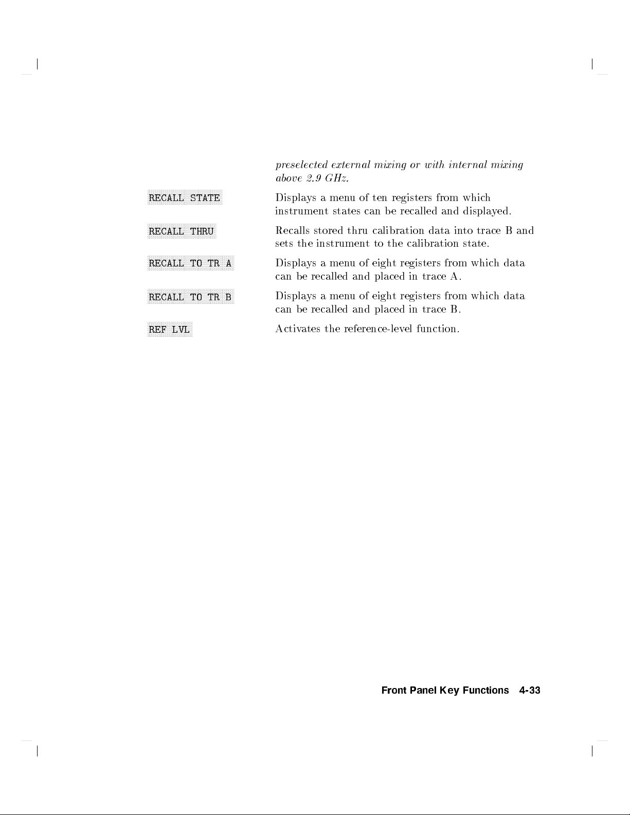
NNNNNNNNNNNNNNNNNNNNNNNNNNNNNNNNNNNNNN
RECALL STATE
NNNNNNNNNNNNNNNNNNNNNNNNNNNNNNNNNNN
RECALL THRU
NNNNNNNNNNNNNNNNNNNNNNNNNNNNNNNNNNNNNNNNNNNN
RECALL TO TR A
NNNNNNNNNNNNNNNNNNNNNNNNNNNNNNNNNNNNNNNNNNNN
RECALL TO TR B
NNNNNNNNNNNNNNNNNNNNNNN
REF LVL
preselected external mixing or with internal mixing
above 2.9 GHz.
Displays a menu of ten registers from which
instrument states can be recalled and displayed.
Recalls stored thru calibration data into trace B and
sets the instrument to the calibration state.
Displays a menu of eight registers from which data
can be recalled and placed in trace A.
Displays a menu of eight registers from which data
can be recalled and placed in trace B.
Activates the reference-level function.
Front Panel Key Functions 4-33

NNNNNNNNNNNNNNNNNNNNNNNNNNNNNNNNNNN
REF LVL ADJ
NNNNNNNNNNNNNNNNNNNNNNNNNNNNNNNNNNNNNNNNNNNN
REF LVL OFFSET
NNNNNNNNNNNNNNNNNNNNNNNNNNNNNNNNNNNNNNNNNNNNNNN
RES BW AUTO MAN
NNNNNNNNNNNNNNNNNNNNNNNNNNNNNNNNNNNNNN
SAMPLER FREQ
NNNNNNNNNNNNNNNNNNNNNNNNNNNNNNNNNNNNNNNNNNNNNNNNNN
SAMPLER HARMONIC
4
5
SAVE
NNNNNNNNNNNNNNNNNNNNNNNNNNNNNNNNNNN
SAVE AMPCOR
NNNNNNNNNNNNNNNNNNNNNNNNNNNNNNNNNNNNNNNNN
SAVE PRSEL PK
NNNNNNNNNNNNNNNNNNNNNNNNNNNNNNNN
SAVE STATE
NNNNNNNNNNNNNNNNNNNNNNNNNNNNNNNNNNNNNN
SAVE TRACE A
NNNNNNNNNNNNNNNNNNNNNNNNNNNNNNNNNNNNNN
SAVE TRACE B
NNNNNNNNNNNNNNNNNNNNNNNNNNNNNNNNNNNNNNNNNNNNNNN
SAVELOCK ON OFF
Permits adjusting the spectrum analyzer internal
gain so that when the calibrator signal is connected
to the input, the reference level at top screen equals
the calibrator amplitude.
Introduces an oset to all amplitude readouts, but
does not change the position of the on-screen trace.
Adjusts the resolution bandwidth of the spectrum
analyzer. Resolution bandwidth may be coupled
to other functions (AUTO) or adjusted manually
(MAN).
Displays the sampling oscillator frequency and lo op
bandwidth compensation value corresponding to the
current start frequency.
Displays the sampler harmonic number corresponding
to the current start frequency.
Accesses a menu for storing instrument data.
Saves the current table of amplitude correction
(ampcor) points.
Saves the current preselector-peak data in a data
table.
For use with preselected external mixing or
with internal mixing above 2.9 GHz.
Displays a menu of ten registers for storing the
current instrument state.
Displays a menu of eight registers for storing trace
contents.
Displays a menu of eight registers for storing trace
contents.
When this function is on, the data in the state and
trace registers cannot be erased or overwritten. No
new data maybe entered into the registers until this
function is turned o.
4-34 Front Panel Key Functions

NNNNNNNNNNNNNNNNNNNNNNNNNNNNNNNNNNNNNN
SCREEN TITLE
NNNNNNNNNNNNNNNNNNNNNNNNNNNNNNNNNNNNNNNNNNNNNNN
SCROLL CORR PTS
NNNNNNNNNNNNNNNNNNNNNNNNNNNNNNNNNNN
SELECT CHAR
Accesses a menu of functions for creating on-screen
titles.
Allows you to scroll through the list of amp cor
amplitude correction points.
Causes the currently selected character in the active
block to appear in the next available p osition of the
title.
4
SGL SWP
5
NNNNNNNNNNNNNNNNNNNNNNNNNNNNNNNNNNNNNNNNN
SIG ID AT MKR
NNNNNNNNNNNNNNNNNNNNNNNNNNNNNNNN
SIG ID!CF
NNNNNNNNNNNNNNNNNNNNNNNNNNNNNNNNNNNNNNNNN
SID ID ON OFF
NNNNNNNNNNNNNNNNNNNNNNNNNNNNNNNNNNNNNNNNNNNN
SIG TRK ON OFF
NNNNNNNNNNNNNNNNNNNNNNNNNNNNNNNNNNNNNN
SIGNAL IDENT
NNNNNNNNNNNNNNNNNNNNNNNNNNNNNNNNNNNNNNNNNNNN
SINGLE MEASURE
Initiates one sweep and activates single-sweep mo de.
Locates the frequency and harmonic number of the
mixer response where a marker has been positioned.
Only available with rmwarerevisions920528 or
with Option 008.
Sets the center frequency to the frequency obtained
from executing
NNNNNNNNNNNNNNNNNNNNNNNNNNNNNNNNNNNNNNNNN
SIG ID AT MKR.Only available with
rmwarerevisions920528 or with Option 008.
Switches manual signal identication on and o.
Signals that are correct for the selected band are
identied by being shifted less than 50 kHz. Limit
frequency spans to less than 20 MHz for best
performance.
920528 or with Option 008.
Only available with rmwarerevisions
Switches the signal tracking function ON and OFF.
When it is ON, it keeps the active marker on the
peak of the signal where it was initially placed and
maintains the center frequency at the marker value.
Accesses a menu of signal identication functions
for use with unpreselected external mixers.
Only
available with rmwarerevisions920528 or with
Option 008.
Puts the spectrum analyzer in single sweep mode,
completing the current measurement.
Front Panel Key Functions 4-35

NNNNNNNNNNNNNNNNNNNNNNNNNNNNNNNNNNNNNNNNNNNNNNN
SOURCE CAL MENU
NNNNNNNNNNNNNNNNN
SPACE
NNNNNNNNNNNNNNNNNNNNNNNNNNNNNNNNNNNNNNNNNNNNNNNNNN
SPACING/BANDWDTH
4
5
SPAN
NNNNNNNNNNNNNN
SPAN
NNNNNNNNNNNNNNNNNNNNNNNNNNNNN
SPAN ZOOM
NNNNNNNNNNNNNNNNNNNNNNNNNNNNNNNNNNNNNNNNNNNN
SQUELCH ON OFF
NNNNNNNNNNNNNNNNNNNNNNNNNNNNNNNNNNNNNNNNNNNN
SRC PWR OFFSET
NNNNNNNNNNNNNNNNNNNNNNNNNNNNNNNNNNNNNNNNNNNN
SRC PWR ON OFF
NNNNNNNNNNNNNNNNNNNNNNNNNNNNNNNNNNNNNNNNNNNNNNNNNN
SRC PWR STP SIZE
NNNNNNNNNNNNNNNNNNNNNNNNNNNNNNNN
START FREQ
NNNNNNNNNNNNNNNNNNNNNNNNNNNNN
STOP FREQ
Accesses a menu of functions used to calibrate
frequency-response errors in test setups when using a
tracking generator.
Places a blank space in the next available character
position in the title.
Accesses the channel spacing and channel bandwidth
softkeys for use in adjacentchannel power (ACP)
measurements.
Activates the frequency span, sets the spectrum
analyzer to center-frequency span mode, and accesses
a menu of span related functions.
Activates the span width function and sets the
spectrum analyzer to center-frequency span mo de.
Tracks a marked signal and activates the span
function so that the span may be reduced quickly
without losing the signal from the display.Ifno
marker is present, the peak-search function is
executed before the span is reduced. See also
NNNNNNNNNNNNNNNNNNNNNNNNNNNNNNNNNNNNNNNNNNNN
SIG TRK ON OFF
.
Turns squelch on and o and adjusts the squelch level
for demodulation.
Osets the displayed p ower of the tracking generator.
8560E/EC Option 002 only.
Switches the tracking generator output power on and
o.
Sets the step size of the source po
wer level, the
source power oset, and the power sweep range.
8560E/EC Option 002 only.
Activates the start frequency and sets the spectrum
analyzer to start stop mo de.
Activates the stop frequency and sets the spectrum
analyzer to start stop mo de.
4-36 Front Panel Key Functions

4
SWEEP
5
NNNNNNNNNNNNNNNNNNNNNNNNNNNNNNNNNNNNNNNNNNNN
SWEEP CONT SGL
NNNNNNNNNNNNNNNNNNNNNNNNNNNNNNNNNNNNNNNNN
SWP CPL SR SA
NNNNNNNNNNNNNNNNNNNNNNNNNNNNNNNNNNNNNNNNNNNNNNNNNNNNN
SWP TIME AUTO MAN
NNNNNNNNNNNNNNNNNNNNNNNNNNNNNNNNNNNNNNNNNNNNNNN
THRESHLD ON OFF
NNNNNNNNNNNNNNNNNNNNNNNNNNNNNNNN
TITLE DONE
Activates the sweep time function and accesses a
menuofsweep related functions.
Allows you to select continuous sweep or single sweep
mode.
Selects an auto-coupled sweep time equation for
stimulus-response (SR) measurements with a
tracking generator or for spectrum-analyzer (SA)
measurements.
Adjusts the sweep time of the sp ectrum analyzer.
The sweep time may be coupled to bandwidth and
span settings (AUTO) or adjusted manually (MAN).
Sets a threshold that determines the lower limit of
an active trace. Adjust the threshold using the data
keys, the step keys, or the knob.
Ends editing of the current title.
4
5
TRACE
NNNNNNNNNNNNNNNNNNNNNNNNNNNNN
TRACE A B
NNNNNNNNNNNNNNNNNNNNNNNNNNNNNNNNNNNNNNNNNNNNNNNNNNNNN
TRACKING GENRATOR
NNNNNNNNNNNNNNNNNNNNNNNNNNNNNNNNNNNNNNNNN
TRACKING PEAK
4
5
TRIG
NNNNNNNNNNNNNNNNNNNNNNNNNNNNNNNNNNNNNNNNNNNNNNNNNN
TRIG POL POS NEG
NNNNNNNNNNNNNNNNNNNNNNNNNNNNNNNNNNNNNNNNNNNN
UNITS AUTO MAN
NNNNNNNNNNNNNNNNNNNNNNNNNNNNNNNNNNNNNNNNN
VBW/RBW RATIO
Accesses a menu of trace functions.
Accesses trace-related functions for traces A and B.
Accesses a menu of tracking generator functions.
Adjusts the coarse and ne tracking adjustments
to peak the tracking generator response on the
spectrum analyzer display automatically.
8560E/EC
Option 002 only.
Accesses a menu of trigger functions.
Sets the sweep to trigger on the rising edge (POS) or
the falling edge (NEG) of the trigger signal.
Accesses a menu of amplitude units. AUTO
indicated default units for the amplitude scale are in
use. MAN indicates other units can be selected.
Displays the coupling ratio between the video
bandwidth and the resolution bandwidth.
Front Panel Key Functions 4-37

NNNNNNNNNNNNNNNNNNNNNNNNNNNNNNNNNNNNNNNNN
V/GHz .25 .50
NNNNNNNNNNNNNNNNNNNNNNNNNNNNNNNNNNNNNNNNNNNN
VID AVG ON OFF
NNNNNNNNNNNNNNNNN
VIDEO
NNNNNNNNNNNNNNNNNNNN
VIEW A
NNNNNNNNNNNNNNNNNNNN
VIEW B
NNNNNNNNNNNNNNNNNNNNNNNNNNNNNNNNNNNNNNNNN
VIEW TBL TRCE
NNNNNNNNNNNNNNNNN
VOLTS
NNNNNNNNNNNNNNNNN
WATTS
NNNNNNNNNNNNNNNNNNNNNNNNNNN
WEIGHT
NNNNNNNNNNNNNNNNNNNNNNNNNN
WEIGHT T
NNNNNNNNNNNNNNNNNNNNNNNNNNNNNNNNNNNNNNNNNNNNNNNNNNNNNNNNNN
WEIGHTINGpCOS OFF
NNNNNNNNNNNNNNNNNNNNNNNNNNNNN
ZERO SPAN
Selects a 0.25 V/GHz or 0.5 V/GHz output
for connector J8 on the rear panel. This is the
frequency-analog voltage (FAV). It is primarily used
with external tracking generators or external mixers.
Turns video averaging on and o. When on, it
smooths the trace byaveraging successive traces.
Sets the trigger to video mo de. Sweep triggers occur
whenever the input signal passes through the video
trigger level, with the selected polarity.
Displays the current contents of trace A, but does
not update the contents.
Displays the current contents of trace B, but does not
update the contents.
Sets the display to show a table of the ACP
measurement results or to show a trace.
Selects volts as the display amplitude units.
Selects watts as the display amplitude units.
Enters thefactor for root-raised-cosine weighting
on an ACP measurement.
Enters the T factor for root-raised-cosine weighting
on an ACP measurement.
Turns on and o ro ot-raised-cosine weighting for an
ACP measurement.
Sets the span to 0 Hz. This displays the input signal
in an amplitude versus time mode which is especially
useful for viewing modulation.
4-38 Front Panel Key Functions

5
Programming Reference
This chapter includes a table with the programming commands group ed
according to similar function, and including a brief denition. When you nd
the desired command, the chapter also includes a more detailed key word
description, syntax information, and an example of how to use each command.
The examples are written in HP BASIC.
If you have a series of front-panel key presses that you would like to write
a program for, there is a cross reference to help y
programming commands.
A list of the 85620A mass memory module commands can b e found in the
section on \Mo dule Commands."
Topics documented in this chapter include:
Programming Commands (functional index)
Key versus Programming Command
Mass Memory Module Commands
Programming Commands (alphabetical index)
Notation Conventions
Syntax Conventions
Secondary Key Word Summary
ou nd the equivalent
Programming Reference 5-1

Programming Commands (functional index)
Programming commands are listed by function in this section. The equivalent
key or softkey and a brief description are also listed. Alternate commands
common to the 8560 E-Series and the 8566A/8568A are included. The
alternate commands are shown in parentheses ().
5-2 Programming Reference

AMPLITUDE
Programming Commands (functional index)
AMPCOR
AMPCORDATA
AMPCOR ON OFF
NNNNNNNNNNNNNNNNNNNNNNNNNNNNNNNN
EDIT AMPCOR
Turns on and o the correction
for system atness.
Enters amplitude correction data.
AMPCORSIZE Indicates the number of
NNNNNNNNNNNNNNNNNNNNNNNNNNNNNNNNNNNNN
correction points.
Recalls ampcor data.
AMPCORRCL
NNNNNNNNNNNNNNNNNNNNNNNNNNNNNNNNNNNNN
RECALL AMPCOR
NNNNNNNNNNNNNNNNNNNNNNNNNNNNNNNN
AMPCORSAVE
AT
SAVE AMPCOR
NNNNNNNNNNNNNNNNNNNNNNNNNNNNNNNNNNNNNNNN
ATTEN AUTO MAN
Saves ampcor data.
Species input attenuation.
NNNNNNNNNNNNNNNNNNNNNNNNNNNNNNNN
AUNITS
COUPLE
AMPTD UNITS
NNNNNNNNNNNNNNNNNNNNNNNNNNNNNNNNNNN
COUPLE AC DC
Species amplitude units for
input, output, and display.
Selects dc or ac coupling.
NNNNNNNNNNNNNNNNNNNNNNNNNNNNN
LG
LN
LOG dB/DIV
NNNNNNNNNNNNNNNNN
N
LINEAR
Species log scale.
Species linear scale.
NNNNNNNNNNNNNNNNNNNNNNNNNNNNNNNNNNNNNNNNNNNNNNNN
MKRL
ML
MARKER!REF LVL
NNNNNNNNNNNNNNNNNNNNNNNNNNNNNNNN
MAX MXR LVL
Moves active marker amplitude
to reference level (E4).
Species the mixer level.
NNNNNNNNNNNNNNNNNNNNNNNNNNNNNNNNNNNNN
NRPOS
PP
NORM REF POSN
NNNNNNNNNNNNNNNNNNNNNNNNNNNNNNNNNNNNNNNN
PRESEL AUTO PK
Adjusts the normalized reference
position.
Peaks preselector.
NNNNNNNNNNNNNNNNNNNNNNNNNNNNNNNNNNNNNNNN
PSDAC
RL
PRESEL MAN ADJ
NNNNNNNNNNNNNNNNNNNNN
REF LVL
NNNNNNNNNNNNNNNNNNNNNNNNNN
or
RANGE LVL
Adjusts or returns
preselector-peak DACnumber.
Species the amplitude value of
the reference level or range level.
NNNNNNNNNNNNNNNNNNNNNNNNNNNNNNNN
RLCAL
ROFFSET
REF LVL ADJ
NNNNNNNNNNNNNNNNNNNNNNNNNNNNNNNNNNNNNNNN
REF LVL OFFSET
Calibrates reference level.
Osets all amplitude readouts
without aecting the trace.
Programming Reference 5-3

Programming Commands (functional index)
AUTO COUPLING
ATAUTO
ATTEN AUTO MAN
NNNNNNNNNN
NNNNNNNNNNNNNNNNNNNNNNNNNNNNNNNNNNNNNNNN
AUTOCPL
RB AUTO
ALL
NNNNNNNNNNNNNNNNNNNNNNNNNNNNNNNNNNNNNNNNNNN
RES BW AUTO MAN
NNNNNNNNNNNNNNNNNNNNNNNNNNNNNNNNNNNNNNNN
RBR
RBW/SPAN RATIO
NNNNNNNNNNNNNNNNNNNNNNNNNNNNNNNNNNNNNNNNNNNNNN
SS AUTO
CF STEP AUTO MAN
NNNNNNNNNNNNNNNNNNNNNNNNNNNNNNNNNNNNNNNNNNNNNNNN
ST AUTO
VB AUTO
SWP TIME AUTO MAN
NNNNNNNNNNNNNNNNNNNNNNNNNNNNNNNNNNNNNNNNNNNNNNNN
VIDEO BW AUTO MAN
NNNNNNNNNNNNNNNNNNNNNNNNNNNNNNNNNNNNN
VBR
VBW/RBW RATIO
AUXILIARY CONTROL
NNNNNNNNNNNNNNNNNNNNNNNNNNNNNNNNNNNNNNNNNNNNNN
CNVLOSS
AVERAGE CNV LOSS
NNNNNNNNNNNNNNNNNNNNNNNNNNNNNNNNNNNNNNNNNNN
DEMOD
AM DEMOD ON OFF
NNNNNNNNNNNNNNNNNNNNNNNNNNNNNNNNNNNNNNNNNNN
FM DEMOD ON OFF
NNNNNNNNNNNNNNNNNNNNNNNNNNNNN
DEMODAGC
DEMODT
AGC ON OFF
NNNNNNNNNNNNNNNNNNNNNNNNNNNNN
DEMOD TIME
NNNNNNNNNNNNNNNNNNNNNNNNNNNNNNNNNNNNNNNNNNNNNNNN
EXTMXR
EXT MXR PRE UNPRE
(AUTO) Auto-couples the RF attenuator
(CA).
Auto-couples all controls.
(AUTO) Auto-couples resolution
bandwidth (CR).
Species coupling ratio of
resolution bandwidth and
frequency span.
(AUTO) Auto-couples center-frequency
step-size (CS).
(AUTO) Auto-couples sweep time (CT).
(AUTO) Auto-couples video bandwidth
(CV).
Species coupling ratio of video
bandwidth and resolution
bandwidth.
Sets reference-level oset to
compensate for external mixer
conversion loss.
or
Turns demodulation on or o.
Controls demodulation auto gain.
Demodulation time.
Species the external mixing
mode as either preselected or
unpreselected.
5-4 Programming Reference

Programming Commands (functional index)
NNNNNNNNNNNNNNNNNNNNNNNNNNNNNNNNNNNNNNN
FREF
N
10 MHz EXT INT
Species the frequency reference
source.
NNNNNNNNNNNNNNNNNNNNNNNNNN
FULBAND
HNLOCK
FULL BAND
NNNNNNNNNNNNNNNNNNNNNNNNNNNNNNNNNNNNN
LOCK HARMONIC
Sets start and stop frequencies
for full waveguide bands.
Locks to sp ecied harmonic
number.
NNNNNNNNNNNNNNNNNNNNNNNNNNNNNNNN
HNUNLK
LOCK ON OFF
Unlocks the specied harmonic
number.
NNNNNNNNNNNNNNNNNNNNNNNNNNNNNNNNNN
IDCF
SIG ID
!
CF
Sets center frequency to
frequency of SIGID.
IDFREQ Returns frequency of identied
signal.
NNNNNNNNNNNNN
MBIAS
MKN
BIAS
NNNNNNNNNNNNNNNNNNNNNNNNNNNNNNNNNNNNN
MARKER NORMAL
Species the bias level for
external mixers.
Activates marker and moves
marker to specied frequency or
center screen (M2).
Species minimum excursion for
MKPX
NNNNNNNNNNNNNNNNNNNNNNNNNNNNNNNNNNN
PEAK EXCURSN
peak identication.
NNNNNNNNNNNNNNNNNNNNNNNNNNNNNNNNNNNNNNNN
MXRMODE
NORMLIZE
EXTERNAL MIXER
NNNNNNNNNNNNNNNNNNNNNNNNNNNNNNNNNNNNNNNN
INTERNAL MIXER
NNNNNNNNNNNNNNNNNNNNNNNNNNNNNNNNNNNNNNNNNNN
NORMLIZE ON OFF
or
Species either internal or
external mixing.
Activates normalization routine.
NNNNNNNNNNNNNNNNNNNNNNNNNNNNNNNNNNN
NRL
NRPOS
NORM REF LVL
NNNNNNNNNNNNNNNNNNNNNNNNNNNNNNNNNNNNN
NORM REF POSN
Sets the normalized reference
level.
Adjusts the normalized reference
position.
NNNNNNNNNNNNNNNNNNNNNNNNNNNNNNNNNNNNNNNN
PP
PSDAC
PRESEL AUTO PK
NNNNNNNNNNNNNNNNNNNNNNNNNNNNNNNNNNNNNNNN
PRESEL MAN ADJ
Peaks preselector.
Adjusts or returns
preselector-peak DACnumber.
NNNNNNNNNNNNNNNNNNNNNNNNNNNNNNNNNNNNNNNNNNN
RCLOSCAL
RECALL OPN/SHRT
Recalls stored open/short trace
calibration data.
NNNNNNNNNNNNNNNNNNNNNNNNNNNNNNNN
RCLTHRU
RECALL THRU
Recalls stored thru calibration
data.
Programming Reference 5-5

Programming Commands (functional index)
RL
NNNNNNNNNNNNNNNNNNNN
N
REF LVL
NNNNNNNNNNNNNNNNNNNNNNNNN
N
,
RANGE LVL
NNNNNNNNNNNNNNNNNNNNNNNNNNNNNNNNNNNNN
SIGID
SQUELCH
SIG ID AT MKR
NNNNNNNNNNNNNNNNNNNNNNNNNNNNNNNNNNNNN
SIG ID ON OFF
NNNNNNNNNNNNNNNNNNNNNNNNNNNNNNNNNNNNNNNN
SQUELCH ON OFF
,
NNNNNNNNNNNNNNNNNNNNNNNNNNNNNNNN
SRCALC
ALC INT EXT
NNNNNNNNNNNNNNNNNNNNNNNNNNNNNNNN
SRCCRSTK
MAN TRK ADJ
NNNNNNNNNNNNNNNNNNNNNNNNNNNNNNNN
SRCFINTK
MAN TRK ADJ
NNNNNNNNNNNNNNNNNNNNNNNNNNNNNNNNNNNNNNNN
SRCPOFS
SRC PWR OFFSET
NNNNNNNNNNNNNNNNNNNNNNNNNNNNNNNNNNNNNNNNNNNNNN
SRCPSTP
SRC PWR STP SIZE
NNNNNNNNNNNNNNNNNNNNNNNNNNNNNNNNNNNNNNNN
SRCPSWP
PWR SWP ON OFF
NNNNNNNNNNNNNNNNNNNNNNNNNNNNNNNNNNNNNNNN
SRCPWR
SRCTKPK
SRC PWR ON OFF
NNNNNNNNNNNNNNNNNNNNNNNNNNNNNNNNNNNN
N
TRACKING PEAK
NNNNNNNNNNNNNNNNNNNNNNNNNNNNNNNNNNN
STOREOPEN
CAL OPN/SHRT
NNNNNNNNNNNNNNNNNNNNNNNNNNNNNNNNNNN
STORESHORT
CAL OPN/SHRT
NNNNNNNNNNNNNNNNNNNNNNNN
STORETHRU
CAL THRU
NNNNNNNNNNNNNNNNNNNNNNNNNNNNNNNNNNNNN
SWPCPL
SWP CPL SR SA
NNNNNNNNNNNNNNNNNNNNNNNNNNNNN
SWPOUT
REAR PANEL
Adjusts the reference level or
range level.
Identies signals for external
mixing frequency bands.
Controls squelch for
demodulation.
Selects internal or external
leveling.
Coarse-tunes the tracking
generator oscillator.
Fine-tunes the tracking generator
oscillator.
Osets the displayed
tracking-generator source power.
Sets the step size of the source
power level.
Controls the power-sweep
function.
Controls the output power of the
tracking generator.
Peaks the tracking generator
response.
Saves open-input calibration data
for use with STORESHORT.
Averages shorted-input and
open-input calibration data and
saves the average.
Stores thru-calibration data.
Selects a stimulus response or
spectrum analyzer coupled sweep
time.
Species the sweep output.
5-6 Programming Reference

BANDWIDTH
Programming Commands (functional index)
RB
RBR
VAVG
VB
VBR
NNNNNNNNNNNNNNNNNNNNNNNNNNNNNNNNNNNNNNNNNNN
RES BW AUTO MAN
NNNNNNNNNNNNNNNNNNNNNNNNNNNNNNNNNNNNNNN
N
RBW/SPAN RATIO
NNNNNNNNNNNNNNNNNNNNNNNNNNNNNNNNNNNNNNNN
VID AVG ON OFF
NNNNNNNNNNNNNNNNNNNNNNNNNNNNNNNNNNNNNNNNNNNNNNNN
VIDEO BW AUTO MAN
NNNNNNNNNNNNNNNNNNNNNNNNNNNNNNNNNNNNN
VID/RBW RATIO
Species resolution bandwidth.
Species the coupling ratio of
resolution bandwidth and
frequency span.
Turns video averaging on or o.
Species video bandwidth.
Species coupling ratio of video
bandwidth and resolution
bandwidth.
Programming Reference 5-7

Programming Commands (functional index)
CALIBRATION
ADJALL
ADJCRT
REALIGN LO & IF
NNNNNNNNNNNNNNNNNNNNNNNNNNNNNNNNNNNNNNNNNNN
CRT ADJ PATTERN
Initiates p ower-on adjustment
sequence.
Initiates CRT adjustment
patterns.
NNNNNNNNNNNNNNNNNNNNNNNNNNNNNNNNNNNNN
NNNNNNNNNNNNNNNNNNNNNNNNNNNNNNNNNNNNNNNNNNN
ADJIF
AMPCOR
IF ADJ ON OFF
NNNNNNNNNNNNNNNNNNNNNNNNNNNNNNNNNNNNNNNNNNNNNNNN
ADJ CURR IF STATE
NNNNNNNNNNNNNNNNNNNNNNNNNNNNNNNN
FULL IF ADJ
NNNNNNNNNNNNNNNNNNNNNNNNNNNNNNNNNNNNN
,
AMPCOR ON OFF
Initiates IF adjustment sequence.
,
Turns on and o the correction
for system atness.
NNNNNNNNNNNNNNNNNNNNNNNNNNNNNNNN
AMPCORDATA
EDIT AMPCOR
Enters amplitude correction data.
AMPCORSIZE Indicates the number of
correction points.
NNNNNNNNNNNNNNNNNNNNNNNNNNNNNNNNNNNNN
AMPCORRCL
AMPCORSAVE
FDIAG
RLCAL
RECALL AMPCOR
NNNNNNNNNNNNNNNNNNNNNNNNNNNNNNNN
SAVE AMPCOR
NNNNNNNNNNNNNNNNNNNNNNNNNNNNNNNNNNNNN
FREQ DIAGNOSE
NNNNNNNNNNNNNNNNNNNNNNNNNNNNNNNNNNN
SAMPLER FREQ
NNNNNNNNNNNNNNNNNNNNNNNNNNNNNNNNNNNNNNNNNNNNNN
SAMPLER HARMONIC
NNNNNNNNNNNNNNNNNNNNNNNNNNNNNNNN
FRAC N FREQ
NNNNNNNNNNNNNNNNNNNNNNNNNNNNNNNNNNN
RAW OSC FREQ
NNNNNNNNNNNNNNNNNNNNNNNNNNNNNNNN
NNNNNNNNNNNNNNNNNNNNN
,
LO FREQ
,
NNNNNNNNNNNNNNNNNNNNNNNN
,
POSTSCLR
REF LVL ADJ
Recalls amp cor data.
Saves ampcor data.
,
Returns the specied frequency
diagnostic information.
,
,
Calibrates reference level.
5-8 Programming Reference

CONFIGURATION
Programming Commands (functional index)
EXTMXR
EXT MXR PRE UNPRE
Selects either preselected or
unpreselected external mixing
NNNNNNNNNNNNNNNNNNNNNNNNNNNNNNNNNNNNNNNNNNNNNNNN
mode.
Returns the model number of
ID
NNNNNNNNNNNNNNNNNNNNNNNNNNNNNNNNNNNNNNNNNNNNNNNN
DATECODE &OPTIONS
analyzer used.
OP Returns the displaylower-left
and upper-right co ordinates.
PLOT
PLOTORG
PLOTSRC
PRINT
4
5
COPY
NNNNNNNNNNNNNNNNNNNNNNNNNNNNNNNNNNNNNNNNNNNNNN
PLOT ORG DSP GRT
NNNNNNNNNNNNNNNNNNNNNNNNNNNNN
PLOT ANNOT
NNNNNNNNNNNNNNNNNNNNNNNNNNNNNNNNNNNNNNNNNNNNNNNN
PLOT ORG DSP GRAT
NNNNNNNNNNNNNNNNNNNNNNNNNNNNNNNNNNN
PLOT TRACE A
4
5
COPY
NNNNNNNNNNNNNNNNNNNNNNNNNNNNNNNNNNNNN
,
PLOT GRATICUL
NNNNNNNNNNNNNNNNNNNNNNNNNNNNNNNNNNN
,
PLOT TRACE B
Sends analyzer displaytoa
plotter.
Scaling points for plot.
,
Species plot source.
,
Sends analyzer displaytoa
printer.
NNNNNNNNNNNNNNNNNNNNNNNNNNNNNNNNNNNNNNNNNNNNNNNN
REV
SER
DATECODE &OPTIONS
NNNNNNNNNNNNNNNNNNNNNNNNNNNNNNNNNNNNNNNNNNNNNNNN
DATECODE &OPTIONS
Returns analyzer rmware
revision date.
Returns analyzer serial number.
COPY
PLOT
PRINT
4
5
with
COPY
NNNNNNNNNNNNNNNNNNNNNNNNNNNNNNNNNNNNNNNNNNNNNNNN
COPY DEV PRNT PLT
4
5
with
COPY
NNNNNNNNNNNNNNNNNNNNNNNNNNNNNNNNNNNNNNNNNNNNNNNN
COPY DEV PRNT PLT
Sends analyzer displaytoa
plotter.
Sends analyzer displaytoa
printer.
Programming Reference 5-9

Programming Commands (functional index)
DISPLAY
ANNOT
BLANK
DL
FDSP
GRAT
TH
TITLE
FREQUENCY
CF
FA
FB
FOFFSET
SS
NNNNNNNNNNNNNNNNNNNNNNNNNNNNNNNNNNN
ANNOT ON OFF
NNNNNNNNNNNNNNNNNNNN
N
BLANK A
NNNNNNNNNNNNNNNNNNNN
N
or
BLANK B
NNNNNNNNNNNNNNNNNNNNNNNNNNNNNNNNNNNNNNNNNNN
DSPL LIN ON OFF
NNNNNNNNNNNNNNNNNNNNNNNNNNNNNNNNNNN
FREQ DSP OFF
NNNNNNNNNNNNNNNNNNNNNNNNNNNNNNN
N
GRAT ON OFF
NNNNNNNNNNNNNNNNNNNNNNNNNNNNNNNNNNNNNNNNNNN
THRESHLD ON OFF
NNNNNNNNNNNNNNNNNNNNNNNNNNNNNNNNNNN
SCREEN TITLE
NNNNNNNNNNNNNNNNNNNNNNNNNNNNNNNN
CENTER FREQ
NNNNNNNNNNNNNNNNNNNNNNNNNNNNN
START FREQ
NNNNNNNNNNNNNNNNNNNNNNNNNN
STOP FREQ
NNNNNNNNNNNNNNNNNNNNNNNNNNNNNNNN
FREQ OFFSET
NNNNNNNNNNNNNNNNNNNNNNNNNNNNNNNNNNNNNNNNNNNNNN
CF STEP AUTO MAN
Turns annotation on or o.
Stores and blanks specied trace
register (A4 and B4).
Species display-line level in
dBm, and turns the display line
on or o. (L0)
Turns all frequency display
annotation o.
Turns graticule on or o.
Species display threshold value.
Writes specied ASCII characters
in title blo ck area of display.
Species center frequency.
Species start frequency.
Species stop frequency.
Species frequency oset.
Species center frequency step
size.
5-10 Programming Reference
 Loading...