


Agilent Technologies
8510C Network Analyzer
Keyword Dictionary
Serial Numbers
This manual applies directly to instruments with
this serial prefix number or above: 3031A.
Part Number: 08510-90280
Printed in USA
May 2001
Revision 3.0
Supersedes January 1994
© Copyright Agilent Technologies 1989, 1991, 1994, 2001

Notice
The information contained in this document is sub ject to change without notice.
AgilentTechnologies makes no warrantyofany kind with regard to this material, including,
but not limited to, the implied warranties of merchantability and tness for a particular
purpose. Agilent shall not be liable for errors contained herein or for incidental or
consequential damages in connection with the furnishing, performance, or use of this material.
Certification
Agilent Technologies certies that this product met its publishedspecications at the time of
shipment from the factory. Agilent further certies that its calibration measurements are
traceable to the United States National Institute of Standards and Technology (NIST, formerly
NBS), to the extent allowed by the Institute's calibration facility, and to the calibration
facilities of other International Standards Organization members.
Warranty
This AgilentTechnologies instrument product is warranted against defects in material and
workmanship for a p eriod of one year from date of delivery. During the warranty period,
Agilent will, at its option, either repair or replace products whic
h prove to be defective.
For warranty service or repair, this product m
ust be returned to a service facility designated
by Agilent. Buyer shall prepay shipping charges to Agilent and Agilent shall pay shipping
charges to return the pro duct to Buyer. However, Buyer shall pay all shipping charges, duties,
and taxes for products returned to Agilent from another country.
Agilentwarrants that its software and rmware designated by Agilent for use with an
instrument will execute its programming instructions when properly installed on that
instrument. Agilent does not warrant that the operation of the instrument, or software, or
rmware will be uninterrupted or error free.
LIMITATION OF WARRANTY
The foregoing warranty shall not apply to defects resulting from improp er or inadequate
maintenance by Buyer, Buyer-supplied software or interfacing, unauthorized modication or
misuse, operation outside of the environmental specications for the product, or improper site
preparation or maintenance.
NO OTHER WARRANTY IS EXPRESSED OR IMPLIED. AGILENT SPECIFICALLY
DISCLAIMS THE IMPLIED WARRANTIES OF MERCHANTABILITY AND FITNESS
FOR A PARTICULAR PURPOSE.
EXCLUSIVE REMEDIES
THE REMEDIES PROVIDED HEREIN ARE BUYER'S SOLE AND EXCLUSIVE
REMEDIES. AGILENT SHALL NOT BE LIABLE FOR ANY DIRECT, INDIRECT,

SPECIAL, INCIDENTAL, OR CONSEQUENTIAL DAMAGES, WHETHER BASED ON
CONTRACT, TORT, OR ANY OTHER LEGAL THEORY.
Assistance
Product maintenance agreements and other customer assistance agreements are available for
Agilent products. For any assistance, contact your nearest Agilent Sales and Service Oce.


c
Copyright AgilentTechnologies 1989, 1991, 1994, 2001 All rights reserved. 1400
FountaingroveParkway, Santa Rosa, CA 95403 U.S.A.

Introduction
This
Agilent 8510C Keyword Dictionary
Operating and Programming Manual
is designed as an extension of the
Agilent 8510
(Part Number 08510-90281). The two should b e used
together. Detailed explanations of 8510 network analyzer operation and functions app ear
in the Operating and Programming Manual. The Menu Structures chapter of this manual
contains complete pictorial outlines of the 8510 menu structure together with programming
mnemonics for each softkey.
The
Agilent 8510C Keyword Dictionary
Programming Manual
by providing a complete alphabetical list of 8510C front-panel hardkeys,
expands upon the
Agilent 8510 Operating and
menu softkeys, and programming mnemonics. Eachentry also includes information about how
to use the function in programmed op eration.
To get the most from this dictionary, rst study the following section, \Using the Dictionary",
which explains each heading and the terms used in the actual entries.
In addition to the keyword listings, this manual also contains:
8510C programming codes
8510C query commands
User display commands
Circuit modeling program
Other programming commands
GPIB universal commands
GPIB addressed commands
Factory preset state values
Hardware state values
8510C caution/tell messages
Subject index
vi

Typeface Conventions
The following conventions are used in the Agilent 8510C-series documentation:
Italics
Italic type is used for emphasis, and for titles of manuals and other publications. It is also
used to designate a variable entry value.
Computer
Computer type is used for information displayed on the instrument and to designate a
programming command or series of commands.
4
Hardkeys
Instrumentkeys are represented in \key cap." You are instructed to
W
WWWWWWWWWWWWWWWWWWWWWWWWWWW
5
press
Softkeys
Softkeys are lo cated along side of the displa
display. These keys are represented in \softkey." You are instructed to
y, and their functions depend on the curren
select
Using the 8510 Keyword Dictionary
This section of the dictionary explains the notation used in the en
refer you to descriptions of each item on the following pages.1
NNNNNNNNNNNNNNNNNNNNNNNNNNNNNNNNNNNNNN
SOFTKEY WORD
Sequence5
,or
GPIB MNEMONIC2
Manual Sequence6
Programming Code3
Description7
See Also
tries. The numbers in circles
4
FRONT PANEL KEY WORD
Main Menu4
1Keyword Entry
NNNNNNNNNNNNNNNNNNNNNNNNNN
There are three kinds of entries:
example shows
4
FRONT PANEL
4
NNNNNNNNNNNNNNNNNNNNNNN
5
,
SOFTKEY
Hardkeys
5
,
Softkeys
,or
GPIB MNEMONIC
, and
Programming Mnemonics
. These are typically followed bya
short description of how the 8510C responds to the keypress or command.
a hardkey.
a softkey.
Program
t
5
. The
,
4
HARDKEY
5
A hardkey entry refers to a front-panel key on the 8510C and gives the name of the key as it
appears on the front-panel.
vii

WWWWWWWWWWWWWWWWWWWWWWWWWWWW
SOFTKEYS
A softkey entry refers to a command that appears on the right-hand side of the LCD/CRT
display and is executed by pressing the corresponding key found immediately to the right.
The name of the softkey given in the entry is as it app ears on the LCD/CRT.
PROGRAMMING MNEMONICS
Mnemonic entries are those that can be executed only through the GPIB and require an
external controller.
2Programming Code
The programming code is the mnemonic equivalent of the hard or softkey. It executes the
command in a programming application. If the entry is a softkey or hardkey that can only be
executed by pressing the key, the listing will show \None."
3Main Menu
This indicates the hardkey (rst-level menu) that must be pressed to access the softkey
. Use
this information to locate the pictorial representation of the menu structure (menu map) of
the network analyzer. Refer to the tabbed chapter \MENU STRUCTURES" for the menu
maps. If the entry is a hardkey or a programming mnemonic, no information is giv
en for this
category.
4Program Sequence
Listed under this heading are the sequential programming commands to use to execute
the function in programmed operation. Details on programming the 8510 network
analyzer system, using an external controller, are given in the \INTRODUCTION to
PROGRAMMING" chapter of the
Conventions used in the program sequences are as follo
MNEMONIC;
Program mnemonics must app ear exactly as shown with no embedded spaces.
Agilent 8510C Operating and Programming Manual
ws:
.
The semicolon (;) is the required terminator character for each program
instruction.
The comma (,) is used to separate a series of values.
(italicized text)
Lower case italicized text describes the range of values for a function or
describes an action that must be p erformed by the operator.
or The word \or" indicates an either/or path. One of the c
selected before continuing.
viii
hoices given must be

value A constant or a preassigned simple or complex variable transferred to the
analyzer. If enclosed in brackets [ ], the entry is optional.
n The lowercase letter \n", indicates that a variable single digit value is
required. If enclosed in brackets [ ], the entry is optional.
[sux] Optional programmer entry units terminator for frequency, time, or voltage
units.
If no optional terminator is specied, the units are the basic units of: Hz,
second, or volt.
5Manual Sequence
This heading lists the hardkeys and softkeys that you must press to execute the function
named in the entry. These keys are listed in the order that they must be pressed. The rst
key pressed is always a hardkey.
In the example, rst press the hardkey STIMULUS
right-hand side of the network analyzer LCD/CRT. Now select the softkey
stimulus menu continues and the softkey
NNNNNNNNNNNNNN
HOLD
4
5
. A menu appears on the
MENU
appears. Finally, select
NNNNNNNNNNNNNN
MORE
NNNNNNNNNNNNNN
HOLD
. The
to execute the
function.
Conventions used in describing complex operations are similar for both man
ual and program
sequences. The following conventions are used in manual sequences only.
entry Indicates that a numeric value is to be entered followed by one of these
terminators:
4
5
= Giga or nano.
G/n
4
5
= Mega or micro.
M/
4
5
= kilo or milli.
k/m
4x15
= basic units: Hz, s, dB, or V.
(text) Text enclosed in parenthesis ( ), describes an action to be p erformed by the
operator.
[text] Text enclosed in brackets denotes optional actions that can be taken.
ix

6Description
Table
The letters \N/A" appear when the information is
Preset
The information in the table for
network analyzer by pressing
automatically by pressing
NNNNNNNNNNNNNNNNNNNNNNNNNNNNNNNNNNNNNNNNNNNN
FACTORY PRESET
NNNNNNNNNNNNNNNNNNNNNNNNNNNNNNNNNNNNNNNNNNNN
FACTORY PRESET
table.
In the example, the continual mo de is set by pressing
This indicates that to operate the network analyzer in the hold mode, the
command to \hold", must be given either by softkey or programming code.
Details on the 8510 preset states are given in the
Programming Manual
. A list describing the factory preset state, mo de, or
value for each function begins in the tabb ed section \STATES" at the end of
this document.
Initialization
The information in the table for
operating system program is rst loaded from the op erating system disk or
upon power-up.
In the example, the initialization state is the same as the preset state.
Coupled
The information in the table for
channel 2 are coupled (the setting for one c
in the other channel), or uncoupled (eachchannel is set independently).
not applicable
preset
is the state, mode, or value set on the
initialization
coupled
indicates whether channel 1 and
hannel is automatically duplicated
to the category.
. When a function is selected
, the function name app ears in the
NNNNNNNNNNNNNNNNNNNNNNNNNNNNNNNNNNNNNNNNNNNN
FACTORY PRESET
.
Agilent 8510 Operating and
is the state or value when the
\Always coupled" indicates that the channels cannot b e set independently.In
the example,
NNNNNNNNNNNNNN
HOLD
is always coupled, indicating that if
one channel then the other channel is in the hold mo de also.
\Always uncoupled" indicates that the channels are always set independently.
\May be uncoupled" indicates that the twochannels can be set independently,
but only by selecting
to the
NNNNNNNNNNNNNNNNNNNNNNNNNNNNNNNNNNNNNNNNNNNNNNNNNN
COUPLED CHANNELS
NNNNNNNNNNNNNNNNNNNNNNNNNNNNNNNNNNNNNNNNNNNNNNNNNNNNNNNN
UNCOUPLED CHANNELS
entry in this dictionary for a list of coupled and
uncoupled functions.
Range
The information in the table for
be entered for the function.
Recalled
The entry in the table for
recalled
pressing a hard or softkey or executing a programming command can be saved
in an Instrument State Register and recalled when the register is recalled. If
the entry is \yes", the function can be stored and recalled. If the information
says \no", the function cannot be stored and recalled.
NNNNNNNNNNNNNN
In the example,
HOLD
can be stored and recalled so the entry is \yes".
Additional Descriptive Information
Additional information is supplied as required.
NNNNNNNNNNNNNN
HOLD
is selected for
before setting the channels. Refer
range
indicates the range of values that may
indicates whether selections made by
x

7See Also
This is the area that lists other entries in this dictionary that can be consulted in connection
with the entry. Occasionally, other documents are referenced. These documents (product
notes) can be found in the
Agilent 8510C Operating and Programming Manual
.
xi


Contents
1. Menu Structures
Introduction . . . . . . . . . . . . . . . . . . . . . . . . . . . . . 1-1
2. Alphabetical List of Programming Codes
Introduction . . . . . . . . . . . . . . . . . . . . . . . . . . . . . 2-1
Notation . . . . . . . . . . . . . . . . . . . . . . . . . . . . . . . 2-2
Example . . . . . . . . . . . . . . . . . . . . . . . . . . . . . . . 2-3
Alphabetical List of Programming Codes . . . . . . . . . . . . . . . . . 2-4
Agilent 8510C Query Commands . . . . . . . . . . . . . . . . . . . . 2-35
User Display . . . . . . . . . . . . . . . . . . . . . . . . . . . . . 2-38
Circuit Modeling Program . . . . . . . . . . . . . . . . . . . . . . . 2-38
Commands . . . . . . . . . . . . . . . . . . . . . . . . . . . . . . 2-39
GPIB Universal Commands . . . . . . . . . . . . . . . . . . . . . . 2-39
GPIB Addressed Commands . . . . . . . . . . . . . . . . . . . . . . 2-40
3. States: Preset, Instrument, Hardware
Factory Preset State/Values . . . . . . . . . . . . . . . . . . . . . . 3-1
Stimulus Functions . . . . . . . . . . . . . . . . . . . . . . . . . 3-1
Parameter Functions . . . . . . . . . . . . . . . . . . . . . . . . 3-1
Format Functions . . . . . . . . . . . . . . . . . . . . . . . . . . 3-1
Response Functions . . . . . . . . . . . . . . . . . . . . . . . . . 3-2
Measurement Calibration Functions . . . . . . . . . . . . . . . . . . 3-2
Domain Functions . . . . . . . . . . . . . . . . . . . . . . . . . 3-2
DisplayFunctions . . . . . . . . . . . . . . . . . . . . . . . . . . 3-2
Marker Functions . . . . . . . . . . . . . . . . . . . . . . . . . . 3-2
System Functions . . . . . . . . . . . . . . . . . . . . . . . . . . 3-2
CopyFunctions . . . . . . . . . . . . . . . . . . . . . . . . . . . 3-3
Disc Functions . . . . . . . . . . . . . . . . . . . . . . . . . . . 3-3
Pulse and Waveguide Systems . . . . . . . . . . . . . . . . . . . . 3-3
Instrument State . . . . . . . . . . . . . . . . . . . . . . . . . . 3-3
Hardware State . . . . . . . . . . . . . . . . . . . . . . . . . . . . 3-4
4. Caution/Tell Messages
Contents-1

A.
NNNNNNNNNNNNNNNNNNNNNNNNNNNNNNNNNNNNNNNNNNNNNNNNNN
ABORT PRINT/PLOT
NNNNNNNNNNNNNNNNNNNNNNNNNNNNNNNN
ADAPTER xx
NNNNNNNNNNNNNNNNNNNNNNNNNNNNNNNNNNNNNNNNNNNNNNN
ADAPTER REMOVAL
NNNNNNNNNNN
ADD
. . . . . . . . . . . . . . . . . . . . . . . . . . . . . . . . . A-4
NNNNNNNNNNNNNNNNNNNNNNNNNN
ADD DONE
NNNNNNNNNNNNNNNNNNNNNNNNNNNNN
ADD LIMIT
NNNNNNNNNNNNNNNNNNNNNNNNNNNNNNNNNNNNNN
ADD MAX LINE
NNNNNNNNNNNNNNNNNNNNNNNNNNNNNNNNNNNNNNNNN
ADD MAX POINT
NNNNNNNNNNNNNNNNNNNNNNNNNNNNNNNNNNNNNN
ADD MIN LINE
NNNNNNNNNNNNNNNNNNNNNNNNNNNNNNNNNNNNNNNNN
ADD MIN POINT
NNNNNNNNNNNNNNNNNNNNNNNNNNNNNNNNNNNNNNNNNNNNNNN
ADDRESS of 8510
NNNNNNNNNNNNNNNNNNNNNNNNNNNNNNNNNNNNNNNNNNNNNNN
ADDRESS of DISC
NNNNNNNNNNNNNNNNNNNNNNNNNNNNNNNNNNNNNNNNNNNNNNNNNNNNNNNNNNNNNN
ADDRESS of PASS-THRU
NNNNNNNNNNNNNNNNNNNNNNNNNNNNNNNNNNNNNNNNNNNNNNNNNNNNNNNNNNNNNNNNNNNNNNNNNNNNN
ADDRESS of PLOTTER: HP-IB
NNNNNNNNNNNNNNNNNNNNNNNNNNNNNNNNNNNNNNNNNNNNNNNNNNNNNNNNNNNNNNNNNNNNNNNNNNNNNNNNNNNNNNNNNNNNNNNNNNNNNNN
ADDRESS of PLOTTER: RS-232 PORT #1
NNNNNNNNNNNNNNNNNNNNNNNNNNNNNNNNNNNNNNNNNNNNNNNNNNNNNNNNNNNNNNNNNNNNNNNNNNNNNNNNNNNNNNNNNNNNNNNNNNNNNNN
ADDRESS of PLOTTER: RS-232 PORT #2
NNNNNNNNNNNNNNNNNNNNNNNNNNNNNNNNNNNNNNNNNNNNNNNNNNNNNNNNNNNNNNNNN
ADDRESS of POWERMETER
NNNNNNNNNNNNNNNNNNNNNNNNNNNNNNNNNNNNNNNNNNNNNNNNNNNNNNNNNNNNNNNNNNNNNNNNNNNNN
ADDRESS of PRINTER: HP-IB
NNNNNNNNNNNNNNNNNNNNNNNNNNNNNNNNNNNNNNNNNNNNNNNNNNNNNNNNNNNNNNNNNNNNNNNNNNNNNNNNNNNNNNNNNNNNNNNNNNNNNNN
ADDRESS of PRINTER: RS-232 PORT #1
NNNNNNNNNNNNNNNNNNNNNNNNNNNNNNNNNNNNNNNNNNNNNNNNNNNNNNNNNNNNNNNNNNNNNNNNNNNNNNNN
ADDRESS of PRINTER: RS-232 PORT #2
NNNNNNNNNNNNNNNNNNNNNNNNNNNNNNNNNNNNNNNNNNNNNNNNNNNNNNNNNNNNNN
ADDRESS of RF SWITCH
NNNNNNNNNNNNNNNNNNNNNNNNNNNNNNNNNNNNNNNNNNNNNNNNNNNNNNNNNNNNNN
ADDRESS of SOURCE #1
NNNNNNNNNNNNNNNNNNNNNNNNNNNNNNNNNNNNNNNNNNNNNNNNNNNNNNNNNNNNNN
ADDRESS of SOURCE #2
NNNNNNNNNNNNNNNNNNNNNNNNNNNNNNNNNNNNNNNNNNNNNNNNNNNNNNNNNNNNNNNNN
ADDRESS of SYSTEM BUS
NNNNNNNNNNNNNNNNNNNNNNNNNNNNNNNNNNNNNNNNNNNNNNNNNNNNNNNNNNN
ADDRESS of TEST SET
NNNNNNNNNNNNNNNNNNNNNNNNNNNNNNNNNNNNNNNNNNNN
ADJUST DISPLAY
NNNNNNNNNNNNNNNNNNNNNNNNNNNNNNNNNNNNNN
ALL SEGMENTS
NNNNNNNNNNNNNNNNNNNNNNNNNNNNNNNNNNNNNNNNNNNN
ANALOG OUT OFF
NNNNNNNNNNNNNNNNNNNNNNNNNNNNNNNNNNNNNNNNN
ANALOG OUT ON
NNNNNNNNNNNNNNNNNNNNNNNNNNNNNNNNNNNNNNNNNNNNNNNNNNNNNNNN
. . . . . . . . . . . . . . . . . . . . . . . . . . . . . A-2
. . . . . . . . . . . . . . . . . . . . . . . . . . . . . . A-5
. . . . . . . . . . . . . . . . . . . . . . . . . . . . . A-6
ATTENUATOR PORT: n
4
5
AUTO
NNNNNNNNNNNNNNNNNNNNNNNNNNNNNNNN
AUTO DELAY
NNNNNNNNNNNNNNNNNNNNNNNNNNNNNNNNNNNNNNNNN
AUTO FEED OFF
NNNNNNNNNNNNNNNNNNNNNNNNNNNNNNNNNNNNNN
AUTO FEED ON
NNNNNNNNNNNNNNNNNNNNNNNNNNNNNNNNNNNNNNNNNNNNNNNNNN
AUX. VOLT OUTPUT
NNNNNNNNNNNNNNNNNNNNNNNNNNNNNNNNNNNNNNNNN
AVERAGING OFF
NNNNNNNNNNNNNNNNNNNNNNNNNNNNNNNNNNNNNNNNNNNNNNNNNNNNNNNNNNNNNN
. . . . . . . . . . . . . . . . . . . . . . . . . . . . . . . . A-33
. . . . . . . . . . . . . . . . . . . . . . . . . . . . . A-33
AVERAGING ON/restart
. . . . . . . . . . . . . . . . . . . . . . . . . . A-1
. . . . . . . . . . . . . . . . . . . . . . . . . . A-3
. . . . . . . . . . . . . . . . . . . . . . . . . . . . A-7
. . . . . . . . . . . . . . . . . . . . . . . . . . . A-8
. . . . . . . . . . . . . . . . . . . . . . . . . . . . A-9
. . . . . . . . . . . . . . . . . . . . . . . . . . . A-10
. . . . . . . . . . . . . . . . . . . . . . . . . . A-11
. . . . . . . . . . . . . . . . . . . . . . . . . . A-12
. . . . . . . . . . . . . . . . . . . . . . . . A-13
. . . . . . . . . . . . . . . . . . . . . . . A-18
. . . . . . . . . . . . . . . . . . . . . . . . A-22
. . . . . . . . . . . . . . . . . . . . . . . . A-23
. . . . . . . . . . . . . . . . . . . . . . . . A-25
. . . . . . . . . . . . . . . . . . . . . . . A-26
. . . . . . . . . . . . . . . . . . . . . . . . A-27
. . . . . . . . . . . . . . . . . . . . . . . . . . . A-28
. . . . . . . . . . . . . . . . . . . . . . . . . . . . A-29
. . . . . . . . . . . . . . . . . . . . . . . . . . . A-30
. . . . . . . . . . . . . . . . . . . . . . . . . . . A-31
. . . . . . . . . . . . . . . . . . . . . . . . . A-32
. . . . . . . . . . . . . . . . . . . . . . . . . . . A-34
. . . . . . . . . . . . . . . . . . . . . . . . . . . . A-35
. . . . . . . . . . . . . . . . . . . . . . . . . . A-36
. . . . . . . . . . . . . . . . . . . . . . . . . . . A-37
. . . . . . . . . . . . . . . . . . . . . . . . A-38
. . . . . . . . . . . . . . . . . . . . . A-14
. . . . . . . . . . . . . . . . A-15
. . . . . . . . . . . . . . . . A-17
. . . . . . . . . . . . . . . . . . . . . A-19
NNNNNNNNNNNNNNNNNNNNNNN
. . . . . . . . . . . . . . . . A-20
. . . . . . . . . . . . . . . . A-21
Contents-2

B.
NNNNNNNNNNNNNNNNNNNNNNNNNNNNNNNNNNNNNNNNNNNNNNNNNNNNNNNNNNNNNN
BACKGROUND INTENSITY
NNNNNNNNNNNNNNNNNNNNNNNNNNNNNNNN
BACK SPACE
4
BACKSPACE
NNNNNNNNNNNNNNNNNNNNNNNNNNNNNNNN
BEEPER OFF
NNNNNNNNNNNNNNNNNNNNNNNNNNNNN
BEEPER ON
NNNNNNNNNNNNNNNNNNNNNNNNNNNNNNNNNNN
BEGIN LIMIT
NNNNNNNNNNNNNNNNNNNNNNNNNNNNNNNNNNNNNNNNNNNN
BEGIN STIMULUS
NNNNNNNNNNNNNNNNN
BLACK
NNNNNNNNNNNNNNNNNNNNNNNNNNNNNNNN
. . . . . . . . . . . . . . . . . . . . . . . . . . . . . . . . B-7
BRIGHTNESS
C.
NNNNNNNNNNNNNNNNNNNNNNNNN
C
n
4
5
CAL
NNNNNNNNNNNNNNNNNNNNNNNNNN
CAL 1 xx
NNNNNNNNNNNNNNNNNNNNNNNNNN
CAL 2 xx
NNNNNNNNNNNNNNNNNNNNNNNNNNNNNNNNNNNNNNNNNNNNNNNNNNNNNNNN
CALIBRATE FLATNESS
NNNNNNNNNNNNNNNNNNNNNNNNNNNNNNNNNNNNNNNNNNNNNNNNNNNNNNNNNNNNNNNNNNNN
CALIBRATE: FULL 2-PORT
NNNNNNNNNNNNNNNNNNNNNNNNNNNNNNNNNNNNNNNNNNNNNNNNNNNNNNNNNNNNNNNNNNNNNNNNNNNNNNNN
CALIBRATE: ONE-PATH 2-PORT
NNNNNNNNNNNNNNNNNNNNNNNNNNNNNNNNNNNNNNNNNNNNNNNNNNNNNNNNNNN
CALIBRATE: RESPONSE
NNNNNNNNNNNNNNNNNNNNNNNNNNNNNNNNNNNNNNNNNNNNNNNNNNNNNNNNNNNNNNNNNNNNNNNNNNNNNNNNNNNNNN
CALIBRATE: RESPONSE & ISOL'N
NNNNNNNNNNNNNNNNNNNNNNNNNNNNNNNNNNNNNNNNNNNNNNNNNNNNNNNNNNNNNNN
CALIBRATE: S111-PORT
NNNNNNNNNNNNNNNNNNNNNNNNNNNNNNNNNNNNNNNNNNNNNNNNNNNNNNNNNNNNNNN
CALIBRATE: S221-PORT
NNNNNNNNNNNNNNNNNNNNNNNNNNNNNNNNNNNNNNNNNNNNNNNNNNNNNNNNNNNNNNNNN
CALIBRATE: TRL 2-PORT
NNNNNNNNNNNNNNNNNNNNNNNNNNNNN
CAL KIT n
NNNNNNNNNNNNNNNNNNNNNNNNNNNNNNNNNNN
CAL KIT 1-2
NNNNNNNNNNNNNNNNNNNNNNNNNNNNN
CAL KIT 1
NNNNNNNNNNNNNNNNNNNNNNNNNNNNN
CAL SET n
NNNNNNNNNNNNNNNNNNNNNNNNNNNNN
CAL SET n
NNNNNNNNNNNNNNNNNNNNNNNNNNNNNNNNNNN
CAL SET 1-8
NNNNNNNNNNNNNNNNNNNNNNNNNNNNNNNNNNN
CAL SET ALL
NNNNNNNNNNNNNNNNNNNNNNNNNNNNNNNNNNNNNNNNNNNNNNNNNNNNNNNN
CAL SET for PORT 1
NNNNNNNNNNNNNNNNNNNNNNNNNNNNNNNNNNNNNNNNNNNNNNNNNNNNNNNN
CAL SET for PORT 2
NNNNNNNNNNNNNNNNNNNNNNNNNNNNNNNNNNNNNNNNNNNNNN
CAL Z0: LINE Z
NNNNNNNNNNNNNNNNNNNNNNNNNNNNNNNNNNNNNNNNNNNNNNNNNNNN
. . . . . . . . . . . . . . . . . . . . . . . . . . . . . . . . C-2
CAL Z0: SYSTEM Z
4
CENTER
NNNNNNNNNNNNNNNNNNNNNNNNNNNNNNNNNNNNNNNNN
CHANGE & SAVE
NNNNNNNNNNNNNNNNNNNNNNNNNNNNNNNNNNNNNNNNNNNNNNN
5
CHANGE CAL TYPE
4
CHANNEL 1
4
CHANNEL 2
NNNNNNNNNNNNNNNNNNNNNNNNNNNNNNNNNNNNNNNNNNNNNNNNNNNNNNNNNNN
CLASS DONE (SPEC'D)
NNNNNNNNNNNNNNNNNNNNNNNNNNNNNNNN
CLEAR LIST
. . . . . . . . . . . . . . . . . . . . . . . . . . . . . B-2
5
. . . . . . . . . . . . . . . . . . . . . . . . . . . . . B-3
. . . . . . . . . . . . . . . . . . . . . . . . . . . . . B-3
. . . . . . . . . . . . . . . . . . . . . . . . . . . . . B-4
. . . . . . . . . . . . . . . . . . . . . . . . . . . . B-5
. . . . . . . . . . . . . . . . . . . . . . . . . . . B-6
. . . . . . . . . . . . . . . . . . . . . . . . . . . . . B-8
. . . . . . . . . . . . . . . . . . . . . . . . . . . . . . C-1
. . . . . . . . . . . . . . . . . . . . . . . . . . . . . . C-3
. . . . . . . . . . . . . . . . . . . . . . . . . . . . . . C-5
. . . . . . . . . . . . . . . . . . . . . . . . . . . . . C-23
. . . . . . . . . . . . . .
NNNNNNNNNNNNNNNNNNNNNNNNNNNNN
,
CAL KIT 2
. . . . . . . . . . . . . . . . . . . . . . . . . . . . . C-26
. . . . . . . . . . . . . . . . . . . . . . . . . . . . . C-29
. . . . . . . . . . . . . . . . . . . . . . . . . . . . C-30
. . . . . . . . . . . . . . . . . . . . . . . . . . . . C-31
. . . . . . . . . . . . . . . . . . . . . . . . . . C-33
0
0
. . . . . . . . . . . . . . . . . . . . . . . . . . . . . . . C-35
. . . . . . . . . . . . . . . . . . . . . . . . . . . C-35
. . . . . . . . . . . . . . . . . . . . . . . . . . C-37
5
. . . . . . . . . . . . . . . . . . . . . . . . . . . . . . C-38
5
. . . . . . . . . . . . . . . . . . . . . . . . . . . . . . C-39
. . . . . . . . . . . . . . . . . . . . . . . . . . . . . C-40
. . . . . . . . . . . . . . . . . . . . . . . . B-1
. . . . . . . . . . . . . . . . . . . . . . . . . C-5
. . . . . . . . . . . . . . . . . . . . . . . C-7
. . . . . . . . . . . . . . . . . . . . C-11
. . . . . . . . . . . . . . . . . . . . . . . . C-15
. . . . . . . . . . . . . . . . . . . C-16
. . . . . . . . . . . . . . . . . . . . . . . C-18
. . . . . . . . . . . . . . . . . . . . . . . C-20
. . . . . . . . . . . . . . . . . . . . . . . C-21
. . . . . . . . . . . . . . C-24
. . . . . . . . . . . . . . . . . . . . . . . . C-25
. . . . . . . . . . . . . . . . . . . . . . . . . C-32
. . . . . . . . . . . . . . . . . . . . . . . . . C-32
. . . . . . . . . . . . . . . . . . . . . . . . . C-34
. . . . . . . . . . . . . . . . . . . . . . . . C-39
Contents-3

NNNNNNNNNNNNNNNNNNNNNNNNNNNNNNNNNNNNNNNNNNN
N
CLEAR LIST YES
NNNNNNNNNNNNNNNNNNNNNNNNNNNNNNNNNNNNNNNNN
CLEAR LIST NO
CLES . . . . . . . . . . . . . . . . . . . . . . . . . . . . . . . . C-43
NNNNNNNNNNNNNN
COAX
NNNNNNNNNNNNNNNNNNNNNNNNNNNNNNNNNNNNNNNNN
COAXIAL DELAY
NNNNNNNNNNNNNNNNN
COLOR
NNNNNNNNNNNNNNNNNNNNNNNNNNNNNNNNNNNNNNNNNNNNNNNNNNNNNNNNNNNNNNNNNNNNNNNNNNNNN
COLUMN 1 DECIMAL POSITION
NNNNNNNNNNNNNNNNNNNNNNNNNNNNNNNNNNNNNNNNNNNNNNNNNNNNNNNNNNNNNNNNNNNNNNNNNNNNN
COLUMN 2 DECIMAL POSITION
NNNNNNNNNNNNNNNNNNNNNNNNNNNNNNNNNNNNNNNNNNNN
COLUMN 1 WIDTH
NNNNNNNNNNNNNNNNNNNNNNNNNNNNNNNNNNNNNNNNNNNN
COLUMN 2 WIDTH
NNNNNNNNNNNNNNNNNNNNNNNNNNNNNNNNNNNNNNNNNNNNNNNNNNNNN
COMPENSATE & SAVE
NNNNNNNNNNNNNNNNNNNNNNNNNNNNNNNNNNNNNNNNNNNN
COMPOSITE SYNC
NNNNNNNNNNNNNNNNNNNNNNNNNNNNNNNNNNNNNNNNNNNNNNNNNNNNNNNNNNN
CONNECTOR CAL KIT 1
NNNNNNNNNNNNNNNNNNNNNNNNNNNNNNNNNNNNNNNNNNNNNNNNNNNNNNNNNNNNNN
CONNECTOR COMPENSATE
NNNNNNNNNNNNNNNNNNNNNNNNNNNNNNNNNNNNNNNNNNNNNNNNNNNNNNNN
CONSTANT FREQUENCY
NNNNNNNNNNNNNNNNNNNNNNNNNNNNN
CONTINUAL
NNNNNNNNNNNNNNNNNNNNNNNNNNNNNNNN
CONVERSION
NNNNNNNNNNNNNNNNNNNNNNNNNNNNNNNNNNNNNNNNNNNN
CONVERT to 1/S
NNNNNNNNNNNNNNNNNNNNNNNNNNNNNNNNNNNNNN
CONVERT to S
NNNNNNNNNNNNNNNNNNNNNNNNNNNNNNNNNNNNNN
CONVERT to Y
NNNNNNNNNNNNNNNNNNNNNNNNNNNNNNNNNNNNNN
. . . . . . . . . . . . . . . . . . . . . . . . . . . . . . . . C-43
. . . . . . . . . . . . . . . . . . . . . . . . . . . . . . . . C-46
CONVERT to Z
4
5
COPY
NNNNNNNNNNNNNNNNNNNNNNNNNNNNNNNNNNN
COPY LIMITS
NNNNNNNNNNNNNNNNNNNNNNNNNNNNNNNNNNNNNNNNNNNN
CORRECTION OFF
NNNNNNNNNNNNNNNNNNNNNNNNNNNNNNNNNNNNNNNNN
CORRECTION ON
NNNNNNNNNNNNNNNNNNNNNNNNNNNNNNNNNNNNNNNNNNNNNNNNNN
COUPLED CHANNELS
NNNNNNNNNNNNNNNNNNNNNNNNNNNNNNNNNNNNNNNNN
CREATE & SAVE
NNNNNNNNNNNNNNNNNNNNNNN
CRT OFF
NNNNNNNNNNNNNN
CYAN
. . . . . . . . . . . . . . . . . . . . . . . . . . . . . . . . C-62
. . . . . . . . . . . . . . . . . . . . . . . . . . . . . . C-68
. . . . . . . . . . . . . . . . . . . . . . . . . . . . . . . . C-69
. . . . . . . . . . . . . . . . . . . . . . . . . . . C-42
. . . . . . . . . . . . . . . . . . . . . . . . . . . C-42
. . . . . . . . . . . . . . . . . . . . . . . . . . . C-45
. . . . . . . . . . . . . . . . . . . . . C-47
. . . . . . . . . . . . . . . . . . . . . C-48
. . . . . . . . . . . . . . . . . . . . . . . . . . . C-49
. . . . . . . . . . . . . . . . . . . . . . . . . . . C-50
. . . . . . . . . . . . . . . . . . . . . . . . . C-51
. . . . . . . . . . . . . . . . . . . . . . . . . . . C-52
NNNNNNNNNNNNNNNNNNNNNNNNNNNNNNNNNNNNNNNNNNNNNNNNNNNNNNNNNNN
,
CONNECTOR CAL KIT 2
. . . . . . . . . . . . . C-53
. . . . . . . . . . . . . . . . . . . . . . . . C-54
. . . . . . . . . . . . . . . . . . . . . . . . . C-55
. . . . . . . . . . . . . . . . . . . . . . . . . . . . . C-56
. . . . . . . . . . . . . . . . . . . . . . . . . . . . . C-57
. . . . . . . . . . . . . . . . . . . . . . . . . . . C-58
. . . . . . . . . . . . . . . . . . . . . . . . . . . . C-59
. . . . . . . . . . . . . . . . . . . . . . . . . . . . C-60
. . . . . . . . . . . . . . . . . . . . . . . . . . . . C-61
. . . . . . . . . . . . . . . . . . . . . . . . . . . . C-63
. . . . . . . . . . . . . . . . . . . . . . . . . . . C-64
. . . . . . . . . . . . . . . . . . . . . . . . . . . C-65
. . . . . . . . . . . . . . . . . . . . . . . . . . C-66
. . . . . . . . . . . . . . . . . . . . . . . . . . . C-67
D.
NNNNNNNNNNNNNNNNNNNNNNNNNNNNNNNN
DATA: DATA
NNNNNNNNNNNNNNNNNNNNNNNNNNNNNNNNNNNNNNNNNNNNNNN
DATA: FORMATTED
NNNNNNNNNNNNNNNNNNNNNNNNNNNNNNNNNNNNNNNNNNNNNNNNNNNNNNNNNNN
DATA from CHANNEL 1
NNNNNNNNNNNNNNNNNNNNNNNNNNNNNNNNNNNNNNNNNNNNNNNNNNNNNNNNNNN
DATA from CHANNEL 2
NNNNNNNNNNNNNNNNNNNNNNNNNNNNNNNNNNNNNNNNNNNNNNNNN
DATA
NNNNNNNNNNNNNNNNNNNNNNNNNNNNN
DATA: RAW
NNNNNNNNNNNNNNNNNNNNNNNNNNNNNNNNNNNNNNNNNNNNNNNNNNNNNNNNNNN
DATE/TIME FUNCTIONS
NNNNNNNNNNNNNNNNNNNNNNNNNNNNNNNNNNNNNNNNN
DATE/TIME OFF
NNNNNNNNNNNNNNNNNNNNNNNNNNNNNNNNNNNNNN
DATE/TIME ON
DEBUOFF . . . . . . . . . . . . . . . . . . . . . . . . . . . . . . D-10
DEBUON . . . . . . . . . . . . . . . . . . . . . . . . . . . . . . D-11
Contents-4
!
MEMORY n
. . . . . . . . . . . . . . . . . . . . . . . . . . . . . D-1
. . . . . . . . . . . . . . . . . . . . . . . . . . D-2
. . . . . . . . . . . . . . . . . . . . . . . . D-3
. . . . . . . . . . . . . . . . . . . . . . . . D-4
. . . . . . . . . . . . . . . . . . . . . . . . . . D-4
. . . . . . . . . . . . . . . . . . . . . . . . . . . . . D-6
. . . . . . . . . . . . . . . . . . . . . . . . D-7
. . . . . . . . . . . . . . . . . . . . . . . . . . . D-8
. . . . . . . . . . . . . . . . . . . . . . . . . . . . D-9

NNNNNNNNNNNNNNNNNNNNNN
N
DEFAULT
NNNNNNNNNNNNNNNNNNNNNNNNNNNNNNNNNNNNNNNNNNNN
DEFAULT COLORS
NNNNNNNNNNNNNNNNNNNNNNNNNNNNNNNNNNNNNNNNNNNNNNNNNNNNNNNN
DEFAULT PEN NUMBRS
NNNNNNNNNNNNNNNNNNNNNNNNNNNNNNNNNNNNNNNNNNNNNNNNNNNNNNNNNNNNNN
DEFAULT to MEMORY: n
NNNNNNNNNNNNNNNNNNNNNNNNNNNNNNNNNNN
DEFINE LIST
NNNNNNNNNNNNNNNNNNNNNNNNNNNNNNNNNNN
DEFINE PLOT
NNNNNNNNNNNNNNNNNNNNNNNNNNNNNNNNNNNNNN
DEFINE PRINT
NNNNNNNNNNNNNNNNNNNNNNNNNNNNNNNNNNNNNNNNNNNNNNNNNN
DEFINE: RECEIVER
NNNNNNNNNNNNNNNNNNNNNNNNNNNNNNNNNNNNNNNNNNNNNNNNNN
DEFINE: SOURCE 1
NNNNNNNNNNNNNNNNNNNNNNNNNNNNNNNNNNNNNNNNNNNNNNNNNN
DEFINE: SOURCE 2
NNNNNNNNNNNNNNNNNNNNNNNNNNNNNNNNNNNNNNNNNNNNNNN
DEFINE STANDARD
4
DELAY
NNNNNNNNNNNNNNNNNNNNNNNNNNNNNNNNNNN
DELAY TABLE
NNNNNNNNNNNNNNNNNNNN
DELETE
NNNNNNNNNNNNNNNNNNNNNNNNNNNNNNNNNNNNNNNNNNNNNNNNNNNNN
DELETE ALL LIMITS
NNNNNNNNNNNNNNNNNNNNNNNNNNNNNNNNNNNNNNNNNNNN
DELETE CAL SET
NNNNNNNNNNNNNNNNNNNNNNNNNNNNNNNNNNN
DELETE FILE
NNNNNNNNNNNNNNNNNNNNNNNNNNNNNNNNNNNNNN
DELETE LIMIT
NNNNNNNNNNNNNNNNNNNNNNNNNNNNNNNNNNN
1 MODE MENU
NNNNNNNNNNNNNNNNN
1 OFF
NNNNNNNNNNNNNNNNNNNNNNNNNNNNN
1 REF = n
NNNNNNNNNNNNNNNNNNNNNNNNNNNNNNNNNNN
DENOMINATOR
NNNNNNNNNNNNNNNNNNNNNNNNNNNNNNN
DENOM.: a1. . . . . . . . . . . . . . . . . . . . . . . . . . . . . D-35
NNNNNNNNNNNNNNNNNNNNNNNNNNNNNNN
DENOM.: a2. . . . . . . . . . . . . . . . . . . . . . . . . . . . . D-36
NNNNNNNNNNNNNNNNNNNNNN
NNNNNNNNN
DENOM.: b1. . . . . . . . . . . . . . . . . . . . . . . . . . . . . D-36
NNNNNNNNNNNNNNNNNNNNNNNNNNNNNNNNNNNNNNNNNNNNNNNNNN
DENOM.: NO RATIO
NNNNNNNNNNNNNNNNNNNNNNNNNNNNNNNNNNNNNNNNNNNNNNNNNNNNNNNNNNN
DETECTOR: NORMAL BW
NNNNNNNNNNNNNNNNNNNNNNNNNNNNNNNNNNNNNNNNNNNNNNNNNNNNN
DETECTOR: WIDE BW
NNNNNNNNNNNNNNNNNNNNNNNNNNNNN
DIRECTORY
4
5
DISC
NNNNNNNNNNNNNNNNNNNNNNNNNNNNNNNNNNNNNNNNNNNNNNNNNN
DISC UNIT NUMBER
NNNNNNNNNNNNNNNNNNNNNNNNNNNNNNNNNNN
DISC VOLUME
4
DISPLAY
NNNNNNNNNNNNNNNNNNNNNNNNNNNNNNNNNNNNNNNNNNNNNNNNNNNNN
DISPLAY FUNCTIONS
NNNNNNNNNNNNNNNNNNNNNNNNNNNNNNNNNNNNNNNNN
DISPLAY: DATA
NNNNNNNNNNNNNNNNNNNNNNNNNNNNNNNNNNNNNNNNNNNNNNNNNNNNNNNNNNNNNNNNNNNNNNN
DISPLAY: MATH(operator)
NNNNNNNNNNNNNNNNNNNNNNNNNNNNNNNNNNNNNNNNNNNNNNNNNNNNNNNNNNNNNNNNNNNNNNNNNN
DISPLAY: DATA and MEMORY
NNNNNNNNNNNNNNNNNNNNNNNNNNNNNNNNNNNNNNNNNNNNNNN
DISPLAY: MEMORY
NNNNNNNNNNNNNNNNNNNNNNNNNNNNNNNNNNNNNN
DISPLAY MODE
NNNNNNNNNNNNNNNNNNNNNNNNNNNNNNNN
DIVIDE (/)
4
DOMAIN
. . . . . . . . . . . . . . . . . . . . . . . . . . . . . . D-11
. . . . . . . . . . . . . . . . . . . . . . . . . . . D-13
. . . . . . . . . . . . . . . . . . . . . . . . . D-14
. . . . . . . . . . . . . . . . . . . . . . . . D-15
. . . . . . . . . . . . . . . . . . . . . . . . . . . . D-17
. . . . . . . . . . . . . . . . . . . . . . . . . . . . D-18
. . . . . . . . . . . . . . . . . . . . . . . . . . . . D-19
. . . . . . . . . . . . . . . . . . . . . . . . . . D-20
. . . . . . . . . . . . . . . . . . . . . . . . . . D-22
. . . . . . . . . . . . . . . . . . . . . . . . . . D-22
. . . . . . . . . . . . . . . . . . . . . . . . . . D-23
5
. . . . . . . . . . . . . . . . . . . . . . . . . . . . . . . D-24
. . . . . . . . . . . . . . . . . . . . . . . . . . . . D-25
. . . . . . . . . . . . . . . . . . . . . . . . . . . . . . . D-26
. . . . . . . . . . . . . . . . . . . . . . . . . D-27
. . . . . . . . . . . . . . . . . . . . . . . . . . . D-28
. . . . . . . . . . . . . . . . . . . . . . . . . . . . D-29
. . . . . . . . . . . . . . . . . . . . . . . . . . . . D-30
. . . . . . . . . . . . . . . . . . . . . . . . . . . . D-31
. . . . . . . . . . . . . . . . . . . . . . . . . . . . . . . . D-32
. . . . . . . . . . . . . . . . . . . . . . . . . . . . . D-32
. . . . . . . . . . . . . . . . . . . . . . . . . . . . D-34
. . . . . . . . . . . . . . . . . . . . . . . . . . D-37
. . . . . . . . . . . . . . . . . . . . . . . . D-37
. . . . . . . . . . . . . . . . . . . . . . . . . D-38
. . . . . . . . . . . . . . . . . . . . . . . . . . . . . D-39
. . . . . . . . . . . . . . . . . . . . . . . . . . . . . . . . D-41
. . . . . . . . . . . . . . . . . . . . . . . . . . D-42
. . . . . . . . . . . . . . . . . . . . . . . . . . . . D-43
5
. . . . . . . . . . . . . . . . . . . . . . . . . . . . . . . D-43
. . . . . . . . . . . . . . . . . . . . . . . . . D-44
. . . . . . . . . . . . . . . . . . . . . . . . . . . D-45
. . . . . . . . . . . . . . . . . . . . . . D-45
. . . . . . . . . . . . . . . . . . . . . D-47
. . . . . . . . . . . . . . . . . . . . . . . . . . D-48
. . . . . . . . . . . . . . . . . . . . . . . . . . . . D-49
. . . . . . . . . . . . . . . . . . . . . . . . . . . . . D-49
5
. . . . . . . . . . . . . . . . . . . . . . . . . . . . . . . D-50
Contents-5

NNNNNNNNNNNNNNNNNNNNNNNNN
N
DONE: xx
NNNNNNNNNNNNNN
DONE
NNNNNNNNNNNNNN
DONE
NNNNNNNNNNNNNNNNNNNNNNNNNNNNNNNN
DONE LOADS
NNNNNNNNNNNNNNNNN
DRIVE
NNNNNNNNNNNNNNNNNNNNNNNNNNNNNNNNNNN
DRIVE: NONE
NNNNNNNNNNNNNNNNNNNNNNNNNNNNNNNNNNNNNNNNN
DRIVE: PORT n
NNNNNNNNNNNNNNNNNNNNNNNNNNNNNNNNNNNNNNNNNNNNNNNNNNNNN
DUAL CHAN OVERLAY
NNNNNNNNNNNNNNNNNNNNNNNNNNNNNNNNNNNNNNNNNNNNNNN
DUAL CHAN SPLIT
NNNNNNNNNNNNNNNNNNNNNNNNNNNNNNNNNNNNNNNNNNNNNNNNNN
DUPLICATE POINTS
NNNNNNNNNNNNNNNNNNNNNNNNNNNNNNNNNNNNNNNNNNNNNNNNNNNNNNNN
DUPLICATES DELETED
NNNNNNNNNNNNNNNNNNNNNNNNNNNNNNNNNNNNNNNNNNNNNNNNNNNNNNNNNNN
DUPLICATES MEASURED
NNNNNNNNNNNNNNNNNNNNNNNNNNNNNNNN
DUTY CYCLE
NNNNNNNNNNNNNNNNNNNNNNNNNNNNNNNN
. . . . . . . . . . . . . . . . . . . . . . . . . . . . . . D-51
. . . . . . . . . . . . . . . . . . . . . . . . . . . . . . . . D-53
. . . . . . . . . . . . . . . . . . . . . . . . . . . . . . . . D-53
. . . . . . . . . . . . . . . . . . . . . . . . . . . . . . . . D-55
DWELL TIME
E.
NNNNNNNNNNNNNN
EDIT
NNNNNNNNNNNNNNNNNNNNNNNNNNNNN
EDIT DONE
NNNNNNNNNNNNNNNNNNNNNNNNNNNNNNNN
EDIT LIMIT
NNNNNNNNNNNNNNNNNNNNNNNNNNNNN
EDIT LIST
NNNNNNNNNNNNNNNNNNNNNNNNNNNNNNNNNNNNNNNNNNNN
EDIT MULT. SRC
NNNNNNNNNNNNNNNNNNNNNNNNNNNNNNNNNNNNNNNNNNNNNNNNNN
ELECTRICAL DELAY
NNNNNNNNNNNNNNNNNNNNNNNNNNNNN
END LIMIT
NNNNNNNNNNNNNNNNNNNNNNNNNNNNNNNNNNNNNN
. . . . . . . . . . . . . . . . . . . . . . . . . . . . . . . . E-1
END STIMULUS
4
ENTRY OFF
NNNNNNNNNNNNNNNNNNNNNNNNNNNNNNNNNNN
5
ERASE TITLE
4
= MARKER
NNNNNNNNNNNNNNNNNNNNNNNNNNNNNNNNNNNNNNNNNNNN
5
. . . . . . . . . . . . . . . . . . . . . . . . . . . . . . E-11
EXTERNAL VIDEO
. . . . . . . . . . . . . . . . . . . . . . . . . . . . . D-54
. . . . . . . . . . . . . . . . . . . . . . . . . . . . D-56
. . . . . . . . . . . . . . . . . . . . . . . . . . . D-57
. . . . . . . . . . . . . . . . . . . . . . . . . D-57
. . . . . . . . . . . . . . . . . . . . . . . . . . D-58
. . . . . . . . . . . . . . . . . . . . . . . . . . D-59
. . . . . . . . . . . . . . . . . . . . . . . . . D-60
. . . . . . . . . . . . . . . . . . . . . . . . D-61
. . . . . . . . . . . . . . . . . . . . . . . . . . . . . D-62
. . . . . . . . . . . . . . . . . . . . . . . . . . . . . D-63
. . . . . . . . . . . . . . . . . . . . . . . . . . . . . E-2
. . . . . . . . . . . . . . . . . . . . . . . . . . . . . E-3
. . . . . . . . . . . . . . . . . . . . . . . . . . . . . E-4
. . . . . . . . . . . . . . . . . . . . . . . . . . . E-5
. . . . . . . . . . . . . . . . . . . . . . . . . . E-7
. . . . . . . . . . . . . . . . . . . . . . . . . . . . . E-8
. . . . . . . . . . . . . . . . . . . . . . . . . . . . E-9
. . . . . . . . . . . . . . . . . . . . . . . . . . . . . E-10
. . . . . . . . . . . . . . . . . . . . . . . . . . . . E-11
. . . . . . . . . . . . . . . . . . . . . . . . . E-12
. .
F.
NNNNNNNNNNNNNNNNNNNNNNNNNNNNNNNNNNNNNNNNNNNN
FACTORY PRESET
FASC . . . . . . . . . . . . . . . . . . . . . . . . . . . . . . . . F-2
NNNNNNNNNNNNNNNNN
FIXED
NNNNNNNNNNNNNNNNNNNNNNNNNNNNNNNNNNNNNN
FLATNESS OFF
NNNNNNNNNNNNNNNNNNNNNNNNNNNNNNNNNNN
FLATNESS ON
FORM1 . . . . . . . . . . . . . . . . . . . . . . . . . . . . . . . F-6
FORM2 . . . . . . . . . . . . . . . . . . . . . . . . . . . . . . . F-8
FORM3 . . . . . . . . . . . . . . . . . . . . . . . . . . . . . . . F-9
FORM4 . . . . . . . . . . . . . . . . . . . . . . . . . . . . . . . F-10
FORM5 . . . . . . . . . . . . . . . . . . . . . . . . . . . . . . . F-12
FORMAT
NNNNNNNNNNNNNNNNNNNNNNNNNNNNN
FORM FEED
NNNNNNNNNNNNNNNNNNNNNNNNNNNNNNNNNNNNNNNNNNNNNNNNNNNNNNNNNNNNNN
FOUR PARAM 1 MARKER/
Contents-6
. . . . . . . . . . . . . . . . . . . . . . . . . . . F-1
. . . . . . . . . . . . . . . . . . . . . . . . . . . . . . . . F-3
. . . . . . . . . . . . . . . . . . . . . . . . . . . . F-4
. . . . . . . . . . . . . . . . . . . . . . . . . . . . F-5
4
5
MENU
. . . . . . . . . . . . . . . . . . . . . . . . . . . F-13
. . . . . . . . . . . . . . . . . . . . . . . . . . . . . F-14
. . . . . . . . . . . . . . . . . . . . . . . . F-15

NNNNNNNNNNNNNNNNNNNNNNNNNNNNNNNNNNNNNNNNNNNNNNNNNNNNNNNNNNNNN
N
FOUR PARAM 5 MARKERS
NNNNNNNNNNNNNNNNNNNNNNNNNNNNNNNNNNNNNNNNNNNNNNNNNNNNNNNN
FOUR PARAM OVERLAY
NNNNNNNNNNNNNNNNNNNNNNNNNNNNNNNNNNNNNNNNNNNNNNNNNN
FOUR PARAM SPLIT
FRER . . . . . . . . . . . . . . . . . . . . . . . . . . . . . . . . F-20
NNNNNNNNNNNNNNNNNNNNNNNNNNNNN
FREQUENCY
NNNNNNNNNNNNNNNNNNNNNNNNNNNNNNNNNNNNNNNNNNNN
FREQUENCY LIST
NNNNNNNNNNNNNNNNNNNNNNNNNNNNNNNNNNNNNNNNN
FREQUENCY OFF
NNNNNNNNNNNNNNNNNNNNNNNNNNNNNNNNNNNNNNNNNNNNNNNNNNNNN
FREQUENCY OF MEAS
NNNNNNNNNNNNNNNNNNNNNNNNNNNNNNNNNNNNNNNNNNNNNNNNNN
. . . . . . . . . . . . . . . . . . . . . . . . . . . . . F-20
. . . . . . . . . . . . . . . . . . . . . . . . . . . F-21
. . . . . . . . . . . . . . . . . . . . . . . . . . . F-22
FREQUENCY SUBSET
FREU . . . . . . . . . . . . . . . . . . . . . . . . . . . . . . . . F-26
NNNNNNNNNNNNNNNNNNNNNNNNNNNNNNNNNNNNNNNNNNNNNNNNNNNNNNNNNNNNNNNNN
FWD ISOL'N ISOL'N STD
NNNNNNNNNNNNNNNNNNNNNNNNNNNNN
FULL PAGE
NNNNNNNNNNNNNNNNNNNNNNNNNNNNNNNNNNNNNNNNNNNNNNNNNNNNNNNNNNNNNNNNNNNNNNNNNNNNNNNNNNN
(FWD ISOLATION CLASS LABEL)
NNNNNNNNNNNNNNNNNNNNNNNNNNNNNNNNNNNNNNNNN
FWD. MATCH xx
NNNNNNNNNNNNNNNNNNNNNNNNNNNNNNNNNNNNNNNNNNNN
FWD. TRANS. xx
G.
NNNNNNNNNNNNNNNNNNNNNNNNNNNNNNNNNNNNNNNNN
GAIN: (MIN) 0
NNNNNNNNNNNNNNNNNNNNNNN
GAIN: 1
NNNNNNNNNNNNNNNNNNNNNNN
GAIN: 2
NNNNNNNNNNNNNNNNNNNNNNN
GAIN: 3
NNNNNNNNNNNNNNNNNNNNNNNNNNNNNNNNNNNNNNNNN
GAIN: (MAX) 4
NNNNNNNNNNNNNNNNNNNNNNNNNNNNNNNN
GAIN: AUTO
NNNNNNNNNNNNNNNNNNNNNNNNNNNNNNNNNNNNNN
GATE: CENTER
NNNNNNNNNNNNNNNNNNNNNNNNNN
GATE OFF
NNNNNNNNNNNNNNNNNNNNNNN
GATE ON
NNNNNNNNNNNNNNNNNNNNNNNNNNNNNNNN
GATE SHAPE
NNNNNNNNNNNNNNNNNNNNNNNNNNNNNNNNNNNNNNNNNNNNNNNNNNNNNNNN
GATE SHAPE MAXIMUM
NNNNNNNNNNNNNNNNNNNNNNNNNNNNNNNNNNNNNNNNNNNNNNNNNNNNNNNN
GATE SHAPE MINIMUM
NNNNNNNNNNNNNNNNNNNNNNNNNNNNNNNNNNNNNNNNNNNNNNNNNNNNN
GATE SHAPE NORMAL
NNNNNNNNNNNNNNNNNNNNNNNNNNNNNNNNNNNNNNNNNNNNNNN
GATE SHAPE WIDE
NNNNNNNNNNNNNNNNNNNNNNNNNNNNNNNN
GATE: SPAN
NNNNNNNNNNNNNNNNNNNNNNNNNNNNNNNNNNN
GATE: START
NNNNNNNNNNNNNNNNNNNNNNNNNNNNNNNN
GATE: STOP
NNNNNNNNNNNNNNNNNNNNNNNNNNNNN
GRATICULE
NNNNNNNNNNNNNNNNNNNNNNNNNNNNNNNNNNNNNNNNNNNNNNNNNN
GRATICULE PEN: n
NNNNNNNNNNNNNNNNN
GREEN
NNNNNNNNNNNNNN
GREY
. . . . . . . . . . . . . . . . . . . . . . . . . . . . . . . . G-17
. . . . . . . . . . . . . . . . . . . . . . . . . . . . . . . . G-18
. . . . . . . . . . . . . . . . . . . . . . . . . . . . . F-28
. . . . . . . . . . . . . . . . . . . . . . . . . . . F-31
. . . . . . . . . . . . . . . . . . . . . . . . . . . F-32
. . . . . . . . . . . . . . . . . . . . . . . . . . . G-1
. . . . . . . . . . . . . . . . . . . . . . . . . . . . . . G-2
. . . . . . . . . . . . . . . . . . . . . . . . . . . . . . G-3
. . . . . . . . . . . . . . . . . . . . . . . . . . . . . . G-3
. . . . . . . . . . . . . . . . . . . . . . . . . . . G-4
. . . . . . . . . . . . . . . . . . . . . . . . . . . . . G-4
. . . . . . . . . . . . . . . . . . . . . . . . . . . . G-5
. . . . . . . . . . . . . . . . . . . . . . . . . . . . . . G-6
. . . . . . . . . . . . . . . . . . . . . . . . . . . . . .
. . . . . . . . . . . . . . . . . . . . . . . . . . . . . G-8
. . . . . . . . . . . . . . . . . . . . . . . . . . . . . G-12
. . . . . . . . . . . . . . . . . . . . . . . . . . . . G-13
. . . . . . . . . . . . . . . . . . . . . . . . . . . . . G-14
. . . . . . . . . . . . . . . . . . . . . . . . . . . . . G-15
. . . . . . . . . . . . . . . . . . . . . . . . F-16
. . . . . . . . . . . . . . . . . . . . . . . . . F-18
. . . . . . . . . . . . . . . . . . . . . . . . . . F-19
. . . . . . . . . . . . . . . . . . . . . . . . . F-23
. . . . . . . . . . . . . . . . . . . . . . . . . . F-24
. . . . . . . . . . . . . . . . . . . . . . . F-26
. . . . . . . . . . . . . . . . . . . . F-29
. . . . . . . . . . . . . . . . . . . . . . . . . G-9
. . . . . . . . . . . . . . . . . . . . . . . . . G-10
. . . . . . . . . . . . . . . . . . . . . . . . . G-11
. . . . . . . . . . . . . . . . . . . . . . . . . . G-12
. . . . . . . . . . . . . . . . . . . . . . . . . . G-16
G-7
Contents-7

H.
NNNNNNNNNNNNNNNNNNNNNNNNNNNNNNNNNNNNNNNNNNNN
HARDWARE STATE
NNNNNNNNNNNNNN
HOLD
NNNNNNNNNNNNNNNNNNNNNNNNNNNNNNNNNNNNNNNNNNNNNNN
HP-IB ADDRESSES
NNNNNNNNNNNNNNNNNNNNNNNNNNNNNNNNNNNNNNNNNNNNNNN
HP-IB CONFIGURE
NNNNNNNNNNNNNNNNNNNNNNNNNNNNNNNNNNNNNNNNNNNNNNNNNNNNNNNNNNNNNNNNNNNNNNNNNNNNN
HP-IB USES FACTORY PRESET
NNNNNNNNNNNNNNNNNNNNNNNNNNNNNNNNNNNNNNNNNNNNNNNNNNNNNNNNNNNNNNNNN
HP-IB USES USR PRESET
NNNNNNNNNNNNNNNNNNNNNNNNNN
H,V SYNC
I.
NNNNNNNNNNNNNNNNNNNNNNN
IF GAIN
NNNNNNNNNNNNNNNNNNNNNNNNNNNNN
IMAGINARY
NNNNNNNNNNNNNNNNNNNNNNNNNNNNNNNNNNNNNNNNNNNNNNN
INITIALIZE DISC
NNNNNNNNNNNNNNNNNNNNNNNNNNNNNNNNNNNNNNNNN
INIT DISC: NO
NNNNNNNNNNNNNNNNNNNNNNNNNNNNNNNNNNNNNNNNNNNN
. . . . . . . . . . . . . . . . . . . . . . . . . . . . . . . . H-2
. . . . . . . . . . . . . . . . . . . . . . . . . . . . . . H-7
. . . . . . . . . . . . . . . . . . . . . . . . . . . . . . I-1
INIT DISC: YES
. . . . . . . . . . . . . . . . . . . . . . . . . . . H-1
. . . . . . . . . . . . . . . . . . . . . . . . . . H-3
. . . . . . . . . . . . . . . . . . . . . . . . . . H-5
. . . . . . . . . . . . . . . . . . . . . H-5
. . . . . . . . . . . . . . . . . . . . . . . H-6
. . . . . . . . . . . . . . . . . . . . . . . . . . . . . I-2
. . . . . . . . . . . . . . . . . . . . . . . . . . I-3
. . . . . . . . . . . . . . . . . . . . . . . . . . . I-4
. . . . . . . . . . . . . . . . . . . . . . . . . . . I-4
INPUCALCn . . . . . . . . . . . . . . . . . . . . . . . . . . . . . I-5
INPUDATA . . . . . . . . . . . . . . . . . . . . . . . . . . . . . I-6
INPUDELA . . . . . . . . . . . . . . . . . . . . . . . . . . . . . I-7
INPUFREL . . . . . . . . . . . . . . . . . . . . . . . . . . . . . I-8
INPUFORM . . . . . . . . . . . . . . . . . . . . . . . . . . . . . I-8
INPULEAS . . . . . . . . . . . . . . . . . . . . . . . . . . . . . I-9
INPURAWn . . . . . . . . . . . . . . . . . . . . . . . . . . . . . I-10
NNNNNNNNNNNNNNNNNNNNNNNNNNNNN
INPUT PWR
NNNNNNNNNNNNNNNNNNNNNNNNNNNNNNNNNNNNNN
INST STATE n
NNNNNNNNNNNNNNNNNNNNNNNNNNNNNNNNNNNNNN
INST STATE n
NNNNNNNNNNNNNNNNNNNNNNNNNNNNNNNNNNNNNN
INST STATE n
NNNNNNNNNNNNNNNNNNNNNNNNNNNNNNNNNNNNNNNNNNNN
INST STATE 1-8
NNNNNNNNNNNNNNNNNNNNNNNNNNNNNNNNNNNNNNNNNNNN
INST STATE ALL
NNNNNNNNNNNNNNNNNNNNNNNNNNNNN
INTENSITY
NNNNNNNNNNNNNNNNNNNNNNNNNNNNNNNNNNNNNNNNNNNN
INVERTED SMITH
NNNNNNNNNNNNNNNNNNNNNNNNNNNNN
ISOLATION
NNNNNNNNNNNNNNNNNNNNNNNNNNNNNNNNNNNNNNNNNNNN
ISOLATION DONE
. . . . . . . . . . . . . . . . . . . . . . . . . . . . . I-11
. . . . . . . . . . . . . . . . . . . . . . . . . . . . I-12
. . . . . . . . . . . . . . . . . . . . . . . . . . . . I-13
. . . . . . . . . . . . . . . . . . . . . . . . . . . . I-14
. . . . . . . . . . . . . . . . . . . . . . . . . . . I-15
. . . . . . . . . . . . . . . . . . . . . . . . . . . I-15
. . . . . . . . . . . . . . . . . . . . . . . . . . . . . I-17
. . . . . . . . . . . . . . . . . . . . . . . . . . . I-18
. . . . . . . . . . . . . . . . . . . . . . . . . . . . . I-19
. . . . . . . . . . . . . . . . . . . . . . . . . . . I-21
K.
KEYC . . . . . . . . . . . . . . . . . . . . . . . . . . . . . . . . K-1
NNNNNNNNNNNNNNNNNNNNNNNNNNNNNNNNNNNNNNNNNNNNNNNNNNNNNNNNNNN
KIT DONE (MODIFIED)
Contents-8
. . . . . . . . . . . . . . . . . . . . . . . . K-3

L.
NNNNNNNNNNNNNNNNNNN
L
NNNNNNNNNNNNNNNNNNNNNNNNNNNNNNNNNNNNNNNNNNNN
LABEL: ADAPTER
NNNNNNNNNNNNNNNNNNNNNNNNNNNNNNNNNNNNNNNNNNNNNNNNNNNNNNNN
LABEL: FWD. ISOL'N
NNNNNNNNNNNNNNNNNNNNNNNNNNNNNNNNNNNNNNNNNNNNNNNNNNNNN
LABEL: FWD. MATCH
NNNNNNNNNNNNNNNNNNNNNNNNNNNNNNNNNNNNNNNNNNNNNNNNNNNNNNNN
LABEL: FWD. TRANS.
NNNNNNNNNNNNNNNNNNNNNNNNNNNNNNNNNNNNNNNNNNNNNNN
LABEL: RESPONSE
NNNNNNNNNNNNNNNNNNNNNNNNNNNNNNNNNNNNNNNNNNNNNNNNNNNNNNNN
LABEL: REV. ISOL'N
NNNNNNNNNNNNNNNNNNNNNNNNNNNNNNNNNNNNNNNNNNNNNNNNNNNNN
LABEL: REV. MATCH
NNNNNNNNNNNNNNNNNNNNNNNNNNNNNNNNNNNNNNNNNNNNNNNNNNNNNNNN
LABEL: REV. TRANS.
NNNNNNNNNNNNNNNNNNNNNNNNNNNNNNNNNN
LABEL: S11A
NNNNNNNNNNNNNNNNNNNNNNNNNNNNNNNNNN
LABEL: S11B
NNNNNNNNNNNNNNNNNNNNNNNNNNNNNNNNNN
LABEL: S11C
NNNNNNNNNNNNNNNNNNNNNNNNNNNNNNNNNN
LABEL: S22A
NNNNNNNNNNNNNNNNNNNNNNNNNNNNNNNNNN
LABEL: S22B
NNNNNNNNNNNNNNNNNNNNNNNNNNNNNNNNNN
LABEL: S22C
NNNNNNNNNNNNNNNNNNNNNNNNNNNNNNNNNNN
LABEL CLASS
NNNNNNNNNNNNNNNNNNNNNNNNNNNNNNNN
LABEL DONE
NNNNNNNNNNNNNNNNNNNNNNNNNNNNN
LABEL KIT
NNNNNNNNNNNNNNNNNNNNNNNNNNNNN
LABEL STD
NNNNNNNNNNNNNNNNNNNNNNNNNNNNNNNN
LEFT LOWER
NNNNNNNNNNNNNNNNNNNNNNNNNNNNNNNNNNN
LEFT MARGIN
NNNNNNNNNNNNNNNNNNNNNNNNNNNNNNNN
LEFT UPPER
NNNNNNNNNNNNNNNNNNNN
LIMITS
NNNNNNNNNNNNNNNNNNNN
LIMITS
NNNNNNNNNNNNNNNNNNNN
LIMITS
NNNNNNNNNNNNNNNNNNNNNNNNNNNNNNNNNNNNNNNNN
LIMITS PEN: n
NNNNNNNNNNNNNNNNNNNNNNNNNNNNNNNN
LIMITS OFF
NNNNNNNNNNNNNNNNNNNNNNNNNNNNN
LIMITS ON
NNNNNNNNNNNNNNNNNNNNNNNNNNNNNNNNNNNNNNNNNNNN
LIMIT TEST OFF
NNNNNNNNNNNNNNNNNNNNNNNNNNNNNNNNNNNNNNNNN
LIMIT TEST ON
NNNNNNNNNNNNNNNNNNNNNNNNNNNNNNNNNNNNNNNNNNNNNNNNNN
LIN mkr on POLAR
NNNNNNNNNNNNNNNNNNNNNNN
LINE xx
NNNNNNNNNNNNNNNNNNNNNNNNNNNNNNNNNNNNNNNNNNNNNNNNNN
LINEAR MAGNITUDE
NNNNNNNNNNNNNNNNNNNNNNNNNNNNNNNNNNNNNNNNNNNNNNNNNNNNNNNNNNNNNNNNN
LIST ALL S PARAMETERS
NNNNNNNNNNNNNNNNNNNNNNNNNNNNNNNNNNN
LIST FORMAT
NNNNNNNNNNNNNNNNNNNNNNNNNNNNNNNNNNNNNNNNNNNNNNN
LIST PARAMETERS
NNNNNNNNNNNNNNNNNNNNNNNNNNNNNNNNNNNNNNNNNNNNNNNNNN
LIST SKIP FACTOR
NNNNNNNNNNNNNNNNNNNNNNNNNNNNNNNNNNNNNNNNNNNNNNNNNNNNN
LIST TRACE VALUES
NNNNNNNNNNNNNN
LOAD
. . . . . . . . . . . . . . . . . . . . . . . . . . . . . . . L-1
n
. . . . . . . . . . . . . . . . . . . . . . . . . . . . . L-8
. . . . . . . . . . . . . . . . . . . . . . . . . . . . . L-8
. . . . . . . . . . . . . . . . . . . . . . . . . . . . . L-9
. . . . . . . . . . . . . . . . . . . . . . . . . . . . . L-9
. . . . . . . . . . . . . . . . . . . . . . . . . . . . . L-10
. . . . . . . . . . . . . . . . . . . . . . . . . . . . . L-10
. . . . . . . . . . . . . . . . . . . . . . . . . . . . . L-12
. . . . . . . . . . . . . . . . . . . . . . . . . . . . . L-12
. . . . . . . . . . . . . . . . . . . . . . . . . . . . . L-14
. . . . . . . . . . . . . . . . . . . . . . . . . . . . . L-15
. . . . . . . . . . . . . . . . . . . . . . . . . . . . . L-17
. . . . . . . . . . . . . . . . . . . . . . . . . . . . . . . L-18
(COLOR) . . . . . . . . .
(plotter menu) . . . . . . . . . . . . . . . . . . . . . . . . L-20
. . . . . . . . . . . . . . . . . . . . . . . . . . . . . L-22
. . . . . . . . . . . . . . . . . . . . . . . . . . . . . L-23
. . . . . . . . . . . . . . . . . . . . . . . . . . . . . . L-27
. . . . . . . . . . . . . . . . . . . . . . . . . . . . . . . . L-34
. . . . . . . . . . . . . . . . . . . . . . . . . . . L-2
. . . . . . . . . . . . . . . . . . . . . . . . . L-4
. . . . . . . . . . . . . . . . . . . . . . . . . L-4
. . . . . . . . . . . . . . . . . . . . . . . . . L-5
. . . . . . . . . . . . . . . . . . . . . . . . . . L-6
. . . . . . . . . . . . . . . . . . . . . . . . . L-6
. . . . . . . . . . . . . . . . . . . . . . . . . L-7
. . . . . . . . . . . . . . . . . . . . . . . . . L-7
. . . . . . . . . . . . . . . . . . . . . . . . . . . . L-11
. . . . . . . . . . . . . . . . . . . . . . . . . . . . L-16
. . . . . . . . . . . . . . . . . L-19
. . . . . . . . . . . . . . . . . . . . . . . . . . . L-21
. . . . . . . . . . . . . . . . . . . . . . . . . . . L-24
. . . . . . . . . . . . . . . . . . . . . . . . . . . L-25
. . . . . . . . . . . . . . . . . . . . . . . . . . L-26
. . . . . . . . . . . . . . . . . . . . . . . . . . L-29
. . . . . . . . . . . . . . . . . . . . . . . L-30
. . . . . . . . . . . . . . . . . . . . . . . . . . . . L-31
. . . . . . . . . . . . . . . . . . . . . . . . . . L-32
. . . . . . . . . . . . . . . . . . . . . . . . . . L-32
. . . . . . . . . . . . . . . . . . . . . . . . . L-33
Contents-9

NNNNNNNNNNNNNNNNNNNNNNNNNNNN
N
LOAD FILE
NNNNNNNNNNNNNNNNNNNNNNNNNNNNNNNNNNNNNNNNNNNN
LOAD NO OFFSET
NNNNNNNNNNNNNNNNNNNNNNNNNNNNNNNNNNN
LOAD OFFSET
4
5
LOCAL
NNNNNNNNNNNNNNNNNNNNNNNNNNNNNNNNNNNNNNNNNNNNNNNNNN
LOCK SPEED: FAST
NNNNNNNNNNNNNNNNNNNNNNNNNNNNNNNNNNNNNNNNNNNNNNNNNNNNNNNN
LOCK SPEED: NORMAL
NNNNNNNNNNNNNNNNNNNNNNNNNNNNNNN
LOCK to a1. . . . . . . . . . . . . . . . . . . . . . . . . . . . . L-41
NNNNNNNNNNNNNNNNNNNNNNNNNNNNNNN
LOCK to a2. . . . . . . . . . . . . . . . . . . . . . . . . . . . . L-42
NNNNNNNNNNNNNNNNNNNNNNNNNNNNNNNNNNNNNN
LOCK to None
NNNNNNNNNNNNNNNNNNNNNNNNNNNNNNNNNNNNNNNNNNNNNNNNNNNNNNNNNNN
LOCK TYPE: EXTERNAL
NNNNNNNNNNNNNNNNNNNNNNNNNNNNNNNNNNNNNNNNNNNNNNNNNNNNNNNNNNN
LOCK TYPE: INTERNAL
NNNNNNNNNNNNNNNNNNNNNNNNNNNNNNNNNNNNNNNNNNNNNNN
LOCK TYPE: None
4
LOG MAG
NNNNNNNNNNNNNNNNNNNNNNNNNNNNNNNNNNNNNNNNNNNNNNNNNN
LOG mkr on POLAR
NNNNNNNNNNNNNNNNNNNNNNNNNNNNNNNNNNNNNNNNNNNNNNNNNNNNN
LOW PASS: IMPULSE
NNNNNNNNNNNNNNNNNNNNNNNNNNNNNNNNNNNNNNNNNNNN
LOW PASS: STEP
NNNNNNNNNNNNNNNNNNNNNNNNNNNNNNNNNNNNNNNNNNNNNNNNNNNNN
LOWBAND FREQUENCY
NNNNNNNNNNNNNNNNNNNNNNNNNNNNNNNNNNNNNNNNNNNNNNNNNNNNN
LOWBAND REFLECT'N
. . . . . . . . . . . . . . . . . . . . . . . . . . . . . L-36
. . . . . . . . . . . . . . . . . . . . . . . . . . . L-37
. . . . . . . . . . . . . . . . . . . . . . . . . . . . L-38
. . . . . . . . . . . . . . . . . . . . . . . . . . . . . . . L-39
. . . . . . . . . . . . . . . . . . . . . . . . . . L-40
. . . . . . . . . . . . . . . . . . . . . . . . . L-41
. . . . . . . . . . . . . . . . . . . . . . . . . . . . L-43
. . . . . . . . . . . . . . . . . . . . . . . . L-43
. . . . . . . . . . . . . . . . . . . . . . . . L-44
. . . . . . . . . . . . . . . . . . . . . . . . . . L-45
5
. . . . . . . . . . . . . . . . . . . . . . . . . . . . . . L-45
. . . . . . . . . . . . . . . . . . . . . . . . . . L-46
. . . . . . . . . . . . . . . . . . . . . . . . . L-47
. . . . . . . . . . . . . . . . . . . . . . . . . . . L-48
. . . . . . . . . . . . . . . . . . . . . . . . . L-49
. . . . . . . . . . . . . . . . . . . . . . . . . L-51
M.
NNNNNNNNNNNNNNNNNNNNNNNNNNNNNNNNNNNNNN
MACHINE DUMP
NNNNNNNNNNNNNNNNNNNNNNNNNNNNNNNNNNNNNNNNNNNNNNNNNN
MAGNITUDE OFFSET
NNNNNNNNNNNNNNNNNNNNNNNNNNNNNNNNNNNNNNNNNNNNNNN
MAGNITUDE SLOPE
4
MARKER
NNNNNNNNNNNNNNNNNNNNNNNNNN
MARKER n
NNNNNNNNNNNNNNNNNNNNNNNNNNNNNNNNNNNNNNNNNNNN
MARKER all OFF
NNNNNNNNNNNNNNNNNNNNNNNNNNNNN
MARKER ON
NNNNNNNNNNNNNNNNNNNNNNN
MARKERS
NNNNNNNNNNNNNNNNNNNNNNNNNNNNNNNNNNNNNNNNNNNNNNNNNNNNNNNNNNN
MARKERS: CONTINUOUS
NNNNNNNNNNNNNNNNNNNNNNNNNNNNNNNNNNNNNNNNNNNNNNNNNNNNN
MARKERS: DISCRETE
NNNNNNNNNNNNNNNNNNNNNNNNNNNNNNNNNNNNNNNNNNNN
MARKERS PEN: n
NNNNNNNNNNNNNNNNNNNNNNNNNNNNNNNNNNNNNNNNNNNNNNNNNNNNN
MARKER to MAXIMUM
NNNNNNNNNNNNNNNNNNNNNNNNNNNNNNNNNNNNNNNNNNNNNNNNNNNNN
MARKER to MINIMUM
NNNNNNNNNNNNNNNNNNNNNNNNNNNNNNNNNNNNNNNNNNNNNNNNNN
MARKER to TARGET
NNNNNNNNNNNNNNNNNNNNNNNNNNNNNNNNNNNNNNNNNNNNNNN
MATH OPERATIONS
NNNNNNNNNNNNNNNNNNNNNNNNNNNNNNNNNNNNNNNNNNNNNNNNNNNNN
5
. . . . . . . . . . . . . . . . . . . . . . . . . . . . . . . M-4
MAXIMUM FREQUENCY
MEASUREMENT
NNNNNNNNNNNNNNNNNNNNNNNNNN
MEMORY n
NNNNNNNNNNNNNNNNNNNNNNNNNNNNNNNN
MEMORY 1-8
NNNNNNNNNNNNNNNNNNNNNNNNNNNNNNNN
MEMORY ALL
. . . . . . . . . . . . . . . . . . . . . . . . . . . . M-1
. . . . . . . . . . . . . . . . . . . . . . . . . . M-2
. . . . . . . . . . . . . . . . . . . . . . . . . . M-3
. . . . . . . . . . . . . . . . . . . . . . . . . . . . . . M-5
. . . . . . . . . . . . . . . . . . . . . . . . . . . M-7
. . . . . . . . . . . . . . . . . . . . . . . . . . . . . M-8
. . . . . . . . . . . . . . . . . . . . . . . . . . . . . . M-9
. . . . . . . . . . . . . . . . . . . . . . . . M-11
. . . . . . . . . . . . . . . . . . . . . . . . . M-11
. . . . . . . . . . . . . . . . . . . . . . . . . . . M-12
. . . . . . . . . . . . . . . . . . . . . . . . . M-13
. . . . . . . . . . . . . . . . . . . . . . . . . M-14
. . . . . . . . . . . . . . . . . . . . . . . . . . M-15
. . . . . . . . . . . . . . . . . . . . . . . . . . M-16
. . . . . . . . . . . . . . . . . . . . . . . . . M-17
4
RESTART
5
. . . . . . . . . . . . . . . . . . . . . . M-18
. . . . . . . . . . . . . . . . . . . . . . . . . . . . . . M-19
. . . . . . . . . . . . . . . . . . . . . . . . . . . . . M-20
. . . . . . . . . . . . . . . . . . . . . . . . . . . . . M-21
MENUOFF . . . . . . . . . . . . . . . . . . . . . . . . . . . . . M-22
MENUON . . . . . . . . . . . . . . . . . . . . . . . . . . . . . . M-22
Contents-10

NNNNNNNNNNNNNNNNNNNNNNNNNNNNNNNNNNNNNNNNNNNNNNNNNNNN
N
MINIMUM FREQUENCY
NNNNNNNNNNNNNNNNNNNNNNNNNNNNNN
MINUS (0)
NNNNNNNNNNNNNNNNNNNNNNNNNNNNNNNNNNNNNN
MKR LIST OFF
NNNNNNNNNNNNNNNNNNNNNNNNNNNNNNNNNNN
MKR LIST ON
NNNNNNNNNNNNNNNNNNNNNNNNNNNNNNNNNNN
MODIFY 1 xx
NNNNNNNNNNNNNNNNNNNNNNNNNNNNNNNNNNN
MODIFY 2 xx
NNNNNNNNNNNNNNNNNNNNNNNNNNNNNNNNNNNNNNNNNNNN
MODIFY CAL SET
NNNNNNNNNNNNNNNNNNNNNNNNNNNNNNNNNNNNNNNNN
MODIFY & SAVE
NNNNNNNNNNNNNNNNNNNNNNNNNNNNNNNNNNNNNNNNN
. . . . . . . . . . . . . . . . . . . . . . . . . . . . . M-24
. . . . . . . . . . . . . . . . . . . . . . . . . . . . M-25
. . . . . . . . . . . . . . . . . . . . . . . . . . . . M-26
. . . . . . . . . . . . . . . . . . . . . . . . . . . . M-27
. . . . . . . . . . . . . . . . . . . . . . . . . . . . M-29
MODIFY COLORS
MONI . . . . . . . . . . . . . . . . . . . . . . . . . . . . . . . . M-33
NNNNNNNNNNNNNN
MORE
NNNNNNNNNNNNNNNNNNNNNNNNNNNNNNNNNNNNNNNNNNNNNNNNNNNNNNNNNNN
MULT. SRC: OFF/SAVE
NNNNNNNNNNNNNNNNNNNNNNNNNNNNNNNNNNNNNNNNNNNNNNNNNNNNNNNN
MULT. SRC: ON/SAVE
NNNNNNNNNNNNNNNNNNNNNNNNNNNNNNNNNNNNNNNNNNNNNNNNNNNNNNNNNNNNNNNNNNNN
MULTIPLIER DENOMINATOR
NNNNNNNNNNNNNNNNNNNNNNNNNNNNNNNNNNNNNNNNNNNNNNNNNNNNNNNNNNNNNN
MULTIPLIER NUMERATOR
NNNNNNNNNNNNNNNNNNNNNNNNNNNNNNNNNNNNNNNNNNNN
. . . . . . . . . . . . . . . . . . . . . . . . . . . . . . . . M-33
MULTIPLY ( * )
N.
NNNNNNNNNNNNNNNNNNNNNNNNNNNNNNNNNNNNNNNNN
NEGATIVE SYNC
NNNNNNNNNNNNNNNNNNNNNNNNNNNNNNNNNNNNNNNNNNNN
NEXT PT HIGHER
NNNNNNNNNNNNNNNNNNNNNNNNNNNNNNNNNNNNNNNNN
NEXT PT LOWER
NNNNNNNNNNNNNNNNNNNNNNNNNNNNNNNNNNNNNNNNNNNNNNNNNN
NUMBER of GROUPS
NNNNNNNNNNNNNNNNNNNNNNNNNNNNNNNNNNNNNNNNNNNNNNNNNN
NUMBER of POINTS
NNNNNNNNNNNNNNNNNNNNNNNNNNNNN
NUMERATOR
NNNNNNNNNNNNNNNNNNNNNNNNNNNNNNNNNNNNNNNN
NUMERATOR: a
NNNNNNNNNNNNNNNNNNNNNNNNNNNNNNNNNNNNNNNN
NUMERATOR: a
NNNNNNNNNNNNNNNNNNNNNNNNNNNNNNNNNNNNNNNN
NUMERATOR: b
NNNNNNNNNNNNNNNNNNNNNNNNNNNNNNNNNNNNNNNN
NUMERATOR: b
. . . . . . . . . . . . . . . . . . . . . . . . . . . . . N-6
1
2
1
2
. . . . . . . . . . . . . . . . . . . . . . . . . M-23
. . . . . . . . . . . . . . . . . . . . . . . . . . . M-30
. . . . . . . . . . . . . . . . . . . . . . . . . . . M-31
. . . . . . . . . . . . . . . . . . . . . . . . . . . M-32
. . . . . . . . . . . . . . . . . . . . . . . . M-34
. . . . . . . . . . . . . . . . . . . . . . . . . M-35
. . . . . . . . . . . . . . . . . . . . . . . M-36
. . . . . . . . . . . . . . . . . . . . . . . . M-37
. . . . . . . . . . . . . . . . . . . . . . . . . . . M-38
. . . . . . . . . . . . . . . . . . . . . . . . . . . N-1
. . . . . . . . . . . . . . . . . . . . . . . . . . . N-2
. . . . . . . . . . . . . . . . . . . . . . . . . . . N-3
. . . . . . . . . . . . . . . . . . . . . . . . . . N-4
. . . . . . . . . . . . . . . . . . . . . . . . . . N-5
. . . . . . . . . . . . . . . . . . . . . . . . . . . N-7
. . . . . . . . . . . . . . . . . . . . . . . . . . . N-8
. . . . . . . . . . . . . . . . . . . . . . . . . . . N-8
. . . . . . . . . . . . . . . . . . . . . . . . . . . N-9
O.
NNNNNNNNNNNNNNNNNNNN
OFFSET
NNNNNNNNNNNNNNNNNNNNNNNNNNNNNNNNNNNNNN
OFFSET DELAY
NNNNNNNNNNNNNNNNNNNNNNNNNNNNNNNNNNNNNNNNNNNNNNNNNN
OFFSET FREQUENCY
NNNNNNNNNNNNNNNNNNNNNNNNNNNNNNNNNNNNNNNNNNNNNNNNNN
OFFSET LOAD DONE
NNNNNNNNNNNNNNNNNNNNNNNNNNNNNNNNNNN
OFFSET LOSS
NNNNNNNNNNNNNNNNNNNNNNNNNNNN
OFFSET Z0. . . . . . . . . . . . . . . . . . . . . . . . . . . . . . O-6
NNNNNNNNNNNNNNNNNNNNNNNNNNNNNNNNNNNNNNNNNNNN
OMIT ISOLATION
NNNNNNNNNNNNNNNNNNNNNNNNNNNNNNNNNNNNNNNNNNNNNNNNNNNNNNNNNNNNNN
OPERATING PARAMETERS
. . . . . . . . . . . . . . . . . . . . . . . . . . . . . . . O-1
. . . . . . . . . . . . . . . . . . . . . . . . . . . . O-2
. . . . . . . . . . . . . . . . . . . . . . . . . . O-3
. . . . . . . . . . . . . . . . . . . . . . . . . . O-4
. . . . . . . . . . . . . . . . . . . . . . . . . . . . O-5
. . . . . . . . . . . . . . . . . . . . . . . . . . . O-7
. . . . . . . . . . . . . . . . . . . . . . . . O-8
OUTPACTI . . . . . . . . . . . . . . . . . . . . . . . . . . . . . O-10
OUTPCALCn . . . . . . . . . . . . . . . . . . . . . . . . . . . . O-11
OUTPDATA.. . . . . . . . . . . . . . . . . . . . . . . . . . . . O-12
OUTPDELA . . . . . . . . . . . . . . . . . . . . . . . . . . . . . O-13
OUTPERRO. . . . . . . . . . . . . . . . . . . . . . . . . . . . . O-14
Contents-11

OUTPFORM . . . . . . . . . . . . . . . . . . . . . . . . . . . . . O-15
OUTPFREL . . . . . . . . . . . . . . . . . . . . . . . . . . . . . O-16
OUTPIDEN . . . . . . . . . . . . . . . . . . . . . . . . . . . . . O-16
OUTPKEY . . . . . . . . . . . . . . . . . . . . . . . . . . . . . O-17
OUTPLEAS . . . . . . . . . . . . . . . . . . . . . . . . . . . . . O-18
OUTPMARK . . . . . . . . . . . . . . . . . . . . . . . . . . . . O-19
OUTPMEMO . . . . . . . . . . . . . . . . . . . . . . . . . . . . O-20
OUTPPLOT . . . . . . . . . . . . . . . . . . . . . . . . . . . . . O-21
OUTPRAWn . . . . . . . . . . . . . . . . . . . . . . . . . . . . . O-22
OUTPSTAT . . . . . . . . . . . . . . . . . . . . . . . . . . . . . O-23
OUTPTITL . . . . . . . . . . . . . . . . . . . . . . . . . . . . . O-24
NNNNNNNNNNNNNNNNNNNNNNNNNNNNNNNN
OUTPUT PWR
P.
NNNNNNNNNNNNNNNNNNNNNNNNNNNNNNNNNNNNNNNNNNNNNNN
PAGE PARAMETERS
NNNNNNNNNNNNNNNNNNNNNNNNNNNNNNNNNNNNNNNNNNNNNNN
PARAMETER LABEL
PARAMETER
NNNNNNNNNNNNNN
PEEK
NNNNNNNNNNNNNNNNNNNNNNNNNNNNNNNNNNNNNNNNNNNNNNNNNNNNNNNN
. . . . . . . . . . . . . . . . . . . . . . . . . . . . . . . . P-3
PEEK/POKE LOCATION
4
NNNNNNNNNNNNNNNNNNNNNNNNNNNNNNNN
NNNNNNNNNNNNNNNNNNNNNNNNNNNNNNNNNNNNNN
NNNNNNNNNNNNNNNNNNNNNNNNNNNNN
NNNNNNNNNNNNNNNNNNNNNNNNNNNNNNNN
NNNNNNNNNNNNNNNNNNNNNNNNNNNNNNNNNNNNNNNNNNNNNNN
NNNNNNNNNNNNNNNNNNNNNNNNNNNNNNNNNNNNNNNNNNNNNNN
NNNNNNNNNNNNNNNNNNNNNNNNNNNNNNNNNNNNNN
5
PHASE
PHASE LOCK
PHASE OFFSET
PLOT: ALL
PLOT: DATA
PLOT: GRATICULE
PLOT: MARKER(S)
PLOT: MEMORY
. . . . . . . . . . . . . . . . . . . . . . . . . . . . . O-25
. . . . . . . . . . . . . . . . . . . . . . . . . . P-1
. . . . . . . . . . . . . . . . . . . . . . . . . . P-2
4
5
MENU
. . . . . . . . . . . . . . . . . . . . . . . . . P-3
. . . . . . . . . . . . . . . . . . . . . . . . . P-4
. . . . . . . . . . . . . . . . . . . . . . . . . . . . . . . P-5
. . . . . . . . . . . . . . . . . . . . . . . . . . . . . P-6
. . . . . . . . . . . . . . . . . . . . . . . . . . . . P-7
. . . . . . . . . . . . . . . . . . . . . . . . . . . . . P-8
. . . . . . . . . . . . . . . . . . . . . . . . . . . . . P-10
. . . . . . . . . . . . . . . . . . . . . . . . . . P-11
. . . . . . . . . . . . . . . . . . . . . . . . . . P-12
. . . . . . . . . . . . . . . . . . . . . . . . . . . . P-13
PLOTMENUOFF . . . . . . . . . . . . . . . . . . . . . . . . . . . P-14
PLOTMENUON . . . . . . . . . . . . . . . . . . . . . . . . . . . P-14
NNNNNNNNNNNNNNNNNNNNNNNNNNNNNNNNNNNNNNNNNNNNNNN
PLOT PARAMETERS
NNNNNNNNNNNNNNNNNNNNNNNNNNNNNNNN
PLOT: TEXT
NNNNNNNNNNNNNNNNNNNNNNNNNNNNNNNNNNN
PLOT: TITLE
NNNNNNNNNNNNNNNNNNNNNNNNNNNNNNNNNNNNNNNNNNNNNNN
PLOT TO PLOTTER
NNNNNNNNNNNNNNNNNNNNNNNNNNNNNNNNNNNNNNNNNNNNNNN
PLOT TO PRINTER
NNNNNNNNNNNNNNNNNNNNNNNNNNNNNNNNNNNNNNNNNNNNNNNNNN
PLOT TYPE: COLOR
NNNNNNNNNNNNNNNNNNNNNNNNNNNNNNNNNNNNNNNNNNNNNNNNNNNNNNNNNNNNNNNNN
PLOT TYPE: MONOCHROME
NNNNNNNNNNNNNNNNNNNNNNNNNN
PLUS (+)
NNNNNNNNNNNNNNNNNNNNNNNNNNNNN
POINTS: n
NNNNNNNNNNNNNN
POKE
NNNNNNNNNNNNNNNNNNNN
PORT n
NNNNNNNNNNNNNNNNNNNNNNNNNNNNNNNNNNNNNNNNNNNNNNN
PORT EXTENSIONS
NNNNNNNNNNNNNNNNNNNNNNNNNNNNNNNNNNNNNNNNNNNNNNNNNNNNN
PORT 1 connectors
NNNNNNNNNNNNNNNNNNNNNNNNNNNNNNNNNNNNNNNNN
POSITIVE SYNC
NNNNNNNNNNNNNNNNN
POWER
. . . . . . . . . . . . . . . . . . . . . . . . . . . . . . . . P-23
. . . . . . . . . . . . . . . . . . . . . . . . . . . . . . . . P-29
. . . . . . . . . . . . . . . . . . . . . . . . . . . . . P-16
. . . . . . . . . . . . . . . . . . . . . . . . . . . . . . P-21
. . . . . . . . . . . . . . . . . . . . . . . . . . . . . P-22
. . . . . . . . . . . . . . . . . . . . . . . . . . . . . . . P-25
. . . . . . . . . . . . . . . . . . . . . . . . . . P-15
. . . . . . . . . . . . . . . . . . . . . . . . . . . . P-17
. . . . . . . . . . . . . . . . . . . . . . . . . . P-18
. . . . . . . . . . . . . . . . . . . . . . . . . . P-19
. . . . . . . . . . . . . . . . . . . . . . . . . . P-20
. . . . . . . . . . . . . . . . . . . . . . . P-20
. . . . . . . . . . . . . . . . . . . . . . . . . . P-26
NNNNNNNNNNNNNNNNNNNNNNNNNNNNNNNNNNNNNNNNNNNNNNNNNNNNN
,
PORT 2 connectors
. . . . . . . . . . . . . . . P-27
. . . . . . . . . . . . . . . . . . . . . . . . . . . P-28
Contents-12

NNNNNNNNNNNNNNNNNNNNNNNNNNNNNNNNNNNNNNNNNNN
N
POWER LEVELING
NNNNNNNNNNNNNNNNNNNNNNNNNNNNNNNN
POWER MENU
NNNNNNNNNNNNNNNNNNNNNNNNNNNNNNNNNNNNNNNNNNNN
POWER SOURCE 1
NNNNNNNNNNNNNNNNNNNNNNNNNNNNNNNNNNNNNNNNNNNN
POWER SOURCE 2
NNNNNNNNNNNNNNNNNNNNNNNNNNNNNNNNNNNNNNNNNNNNNNNNNNNNN
PREDEFINED COLORS
NNNNNNNNNNNNNNNNNNNNNNNNNNNNNNNNNNNNNNNNNNNNNNNNNNNNN
PRESS to CONTINUE
. . . . . . . . . . . . . . . . . . . . . . . . . . . P-30
. . . . . . . . . . . . . . . . . . . . . . . . . . . . . P-30
. . . . . . . . . . . . . . . . . . . . . . . . . . . P-31
. . . . . . . . . . . . . . . . . . . . . . . . . . . P-32
. . . . . . . . . . . . . . . . . . . . . . . . . P-33
. . . . . . . . . . . . . . . . . . . . . . . . . P-34
PRINMENUOFF . . . . . . . . . . . . . . . . . . . . . . . . . . . P-35
PRINMENUON . . . . . . . . . . . . . . . . . . . . . . . . . . . P-36
NNNNNNNNNNNNNNNNNNNNNNNNNNNNNNNNNNNNNNNNNNNNNNNNNN
PRINT: LANDSCAPE
NNNNNNNNNNNNNNNNNNNNNNNNNNNNNNNNNNNNNNNNNNNNNNN
PRINT: PORTRAIT
NNNNNNNNNNNNNNNNNNNNNNNNNNNNNNNNNNNNNNNNNNNNNNNNNN
PRINT TYPE COLOR
NNNNNNNNNNNNNNNNNNNNNNNNNNNNNNNNNNNNNNNNNNNNNNNNNNNNNNNNNNNNNNNNN
PRINT TYPE MONOCHROME
NNNNNNNNNNNNNNNNNNNNNNNNNNNNNNNNNNN
PRINT WIDTH
NNNNNNNNNNNNNNNNNNNNNNNNNNNNNNNNNNNNNNNNNNNNNNNNNNNNNNNN
PRINTER RESOLUTION
4
PRIOR MENU
NNNNNNNNNNNNNNNNNNNNNNNNNNNNNNNNNNNNNN
PULSE CONFIG
NNNNNNNNNNNNNNNNNNNNNNNNNNNNNNNNNNNNNNNNNNNNNNN
PULSE OUT: HIGH
NNNNNNNNNNNNNNNNNNNNNNNNNNNNNNNNNNNNNNNNNNNN
PULSE OUT: LOW
NNNNNNNNNNNNNNNNNNNNNNNNNNNNNNNNNNNNNNNNN
PULSE PROFILE
NNNNNNNNNNNNNNNNNNNNNNNNNNNNNNNNNNN
5
. . . . . . . . . . . . . . . . . . . . . . . . . . . . . P-44
PULSE WIDTH
. . . . . . . . . . . . . . . . . . . . . . . . . . P-37
. . . . . . . . . . . . . . . . . . . . . . . . . . P-38
. . . . . . . . . . . . . . . . . . . . . . . . . . P-40
. . . . . . . . . . . . . . . . . . . . . . . P-40
. . . . . . . . . . . . . . . . . . . . . . . . . . . . P-41
. . . . . . . . . . . . . . . . . . . . . . . . . P-42
. . . . . . . . . . . . . . . . . . . . . . . . . . . . P-44
. . . . . . . . . . . . . . . . . . . . . . . . . . P-45
. . . . . . . . . . . . . . . . . . . . . . . . . . . P-46
. . . . . . . . . . . . . . . . . . . . . . . . . . . P-47
. . . . . . . . . . . . . . . . . . . . . . . . . . . . P-48
R.
NNNNNNNNNNNNNN
RAMP
NNNNNNNNNNNNNN
REAL
4
RECALL
NNNNNNNNNNNNNNNNNNNNNNNNNNNNNNNNNNNNNNNNN
RECALL COLORS
NNNNNNNNNNNNNNNNNNNNNNNNNNNNNNNNNNNNNN
RECEIVER CAL
NNNNNNNNNNN
RED
NNNNNNNNNNNNNNNNNNNNNNNNNNNNNNNNNNNNNNNNN
REDEFINE DONE
NNNNNNNNNNNNNNNNNNNNNNNNNNNNNNNNNNNNNNNNNNNNNNNNNNNNNNNN
. . . . . . . . . . . . . . . . . . . . . . . . . . . . . . . . R-1
. . . . . . . . . . . . . . . . . . . . . . . . . . . . . . . . R-2
5
. . . . . . . . . . . . . . . . . . . . . . . . . . . . . . . R-3
. . . . . . . . . . . . . . . . . . . . . . . . . . . . . . . . . R-7
REDEFINE PARAMETER
4
REF POSN
4
REF VALUE
NNNNNNNNNNNNNNNNNNNNNNNNNNNNNNNNNNNNNNNNNNNNNNNNNNNNNNNNNNN
REFERENCE AMP. GAIN
NNNNNNNNNNNNNNNNNNNNNNNNNNNNN
REFLECT'N
NNNNNNNNNNNNNNNNNNNNNNNNNNNNNNNNNNNNNNNNNNNN
REFLECT'N DONE
NNNNNNNNNNNNNNNNNNNNNNNNNNNNNNNNNNNNNNNNNNNNNNNNNNNNNNNN
Re/Im mkr on POLAR
NNNNNNNNNNNNNNNNNNNNNNNNNNNNNNNNNNNNNN
REPLACE FILE
NNNNNNNNNNNNNNNNNNNNNNNNNNNNNNNNNNNNNN
REPLACE MENU
NNNNNNNNNNNNNNNNNNNNNNNNNNNNNNNNNNN
RESET COLOR
NNNNNNNNNNNNNNNNNNNNNNNNNNNNNNNNNNNNNNNNNNNNNNNNNNNNNNNNNNN
RESET IF CORRECTION
NNNNNNNNNNNNNNNNNNNNNNNNNNNNNNNNNNNNNNNNNNNNNNNNNNNNNNNNNNNNNNNNN
5
. . . . . . . . . . . . . . . . . . . . . . . . . . . . . . R-11
5
. . . . . . . . . . . . . . . . . . . . . . . . . . . . . . R-12
. . . . . . . . . . . . . . . . . . . . . . . . . . . . . R-13
(RESPONSE CLASSLABEL)
RESPONSE
4
MENU
. . . . . . . . . . . . . . . . . . . . . . . . . . . R-4
. . . . . . . . . . . . . . . . . . . . . . . . . . . .
R-5
. . . . . . . . . . . . . . . . . . . . . . . . . . . R-8
. . . . . . . . . . . . . . . . . . . . . . . . . R-8
. . . . . . . . . . . . . . . . . . . . . . . . R-13
. . . . . . . . . . . . . . . . . . . . . . . . . . . R-15
. . . . . . . . . . . . . . . . . . . . . . . . . R-15
. . . . . . . . . . . . . . . . . . . . . . . . . . . . R-16
. . . . . . . . . . . . . . . . . . . . . . . . . . . . R-17
. . . . . . . . . . . . . . . . . . . . . . . . . . . . R-18
. . . . . . . . . . . . . . . . . . . . . . . . R-19
. . . . . . . . . . . . . . . . . . . . . . . R-19
5
. . . . . . . . . . . . . . . . . . . . . . . . . . R-20
Contents-13

NNNNNNNNNNNNNNNNNNNNNNNNNNNNNNNNNNNNNNNNNNNNNN
N
RESTORE DISPLAY
NNNNNNNNNNNNNNNNNNNNNNNNNNNNNNNNNNNNNNNNNNNNNNNNNNNNNNNNNNN
RESUME CAL SEQUENCE
NNNNNNNNNNNNNNNNNNNNNNNNNNNNNNNNNNNNNNNNNNNNNNNNNNNNNNNNNNNNNNNNN
REV ISOL'N ISOL'N STD
NNNNNNNNNNNNNNNNNNNNNNNNNNNNNNNNNNNNNNNNN
REV. MATCH xx
NNNNNNNNNNNNNNNNNNNNNNNNNNNNNNNNNNNNNNNNNNNN
REV. TRANS. xx
NNNNNNNNNNNNNNNNNNNNNNNNNNNNNNNNNNN
RIGHT LOWER
NNNNNNNNNNNNNNNNNNNNNNNNNNNNNNNNNNNNNN
RIGHT MARGIN
NNNNNNNNNNNNNNNNNNNNNNNNNNNNNNNNNNN
RIGHT UPPER
. . . . . . . . . . . . . . . . . . . . . . . . . . R-21
. . . . . . . . . . . . . . . . . . . . . . . . R-22
. . . . . . . . . . . . . . . . . . . . . . . R-23
. . . . . . . . . . . . . . . . . . . . . . . . . . . R-25
. . . . . . . . . . . . . . . . . . . . . . . . . . . R-26
. . . . . . . . . . . . . . . . . . . . . . . . . . . . R-27
. . . . . . . . . . . . . . . . . . . . . . . . . . . . R-28
. . . . . . . . . . . . . . . . . . . . . . . . . . . . R-29
S.
4
5
. . . . . . . . . . . . . . . . . . . . . . . . . . . . . . . . . S-1
S11
4
5
. . . . . . . . . . . . . . . . . . . . . . . . . . . . . . . . . S-2
S12
4
5
. . . . . . . . . . . . . . . . . . . . . . . . . . . . . . . . . S-2
S21
4
5
. . . . . . . . . . . . . . . . . . . . . . . . . . . . . . . . . S-3
S22
NNNNNNNNNNNNNNNNNNNNNNNNN
S11DATA
NNNNNNNNNNNNNNNNNNNNNNNNN
S12DATA
NNNNNNNNNNNNNNNNNNNNNNNNN
S21DATA
NNNNNNNNNNNNNNNNNNNNNNNNN
S22DATA
NNNNNNNNNNNNNNNNNNNNNN
S11MEM
NNNNNNNNNNNNNNNNNNNNNN
S12MEM
NNNNNNNNNNNNNNNNNNNNNN
S21MEM
NNNNNNNNNNNNNNNNNNNNNN
S22MEM
NNNNNNNNNNNNNNNNNNNNNNNNNNNNNNNNNNNNNNNNNNNNNN
S11DATA PEN: n
NNNNNNNNNNNNNNNNNNNNNNNNNNNNNNNNNNNNNNNNNNNNNN
S12DATA PEN: n
NNNNNNNNNNNNNNNNNNNNNNNNNNNNNNNNNNNNNNNNNNNNNN
S21DATA PEN: n
NNNNNNNNNNNNNNNNNNNNNNNNNNNNNNNNNNNNNNNNNNNNNN
S22DATA PEN: n
NNNNNNNNNNNNNNNNNNNNNNNNNNNNNNNNNNNNNNNNNNN
S11MEM PEN: n
NNNNNNNNNNNNNNNNN
S12MEM PEN: n
NNNNNNNNNNNNNNNNNNNNNNNNNNNNNNNNNNNNNNNNNNN
S21MEM PEN: n
NNNNNNNNNNNNNNNNNNNNNNNNNNNNNNNNNNNNNNNNNNN
S22MEM PEN: n
NNNNNNNNNNNNNNNNNNNNNNNNNNNNNNNNNNNNNNNN
S11REFLECT xx
NNNNNNNNNNNNNNNNNNNNNNNNNNNNNNNNNNNNNNNN
S22REFLECT xx
NNNNNNNNNNNNNNNNNNNNNNNNNNNNNNN
(S11): xxA
NNNNNNNNNNNNNNNNNNNNNNNNNNNNNNN
(S11): xxB
NNNNNNNNNNNNNNNNNNNNNNNNNNNNNNN
(S11): xxC
NNNNNNNNNNNNNNNNNNNNNNNNNNNNNNN
(S22): xxA
NNNNNNNNNNNNNNNNNNNNNNNNNNNNNNN
(S22): xxB
NNNNNNNNNNNNNNNNNNNNNNNNNNNNNNN
(S22): xxC
NNNNNNNNNNNNNNNNNNNN
SALMON
. . . . . . . . . . . . . . . . . . . . . . . . . . . . . . S-4
. . . . . . . . . . . . . . . . . . . . . . . . . . . . . . S-5
. . . . . . . . . . . . . . . . . . . . . . . . . . . . . . S-6
. . . . . . . . . . . . . . . . . . . . . . . . . . . . . . S-8
. . . . . . . . . . . . . . . . . . . . . . . . . . . . . . . S-9
. . . . . . . . . . . . . . . . . . . . . . . . . . . . . . . S-10
. . . . . . . . . . . . . . . . . . . . . . . . . . . . . . . S-12
. . . . . . . . . . . . . . . . . . . . . . . . . . . . . . . S-13
. . . . . . . . . . . . . . . . . . . . . . . . . . S-14
. . . . . . . . . . . . . . . . . . . . . . . . . . S-15
. . . . . . . . . . . . . . . . . . . . . . . . . . S-16
. . . . . . . . . . . . . . . . . . . . . . . . . . S-17
NNNNNNNNNNNNNNNNNNNNNNNNNN
. . . . . . . . . . . . . . . . . . . . . . . . . . . S-18
. . . . . . . . . . . . . . . . . . . . . . . . . . . S-19
. . . . . . . . . . . . . . . . . . . . . . . . . . . S-20
. . . . . . . . . . . . . . . . . . . . . . . . . . . S-21
. . . . . . . . . . . . . . . . . . . . . . . . . . . S-22
. . . . . . . . . . . . . . . . . . . . . . . . . . . S-24
. . . . . . . . . . . . . . . . . . . . . . . . . . . . . S-24
. . . . . . . . . . . . . . . . . . . . . . . . . . . . . S-26
. . . . . . . . . . . . . . . . . . . . . . . . . . . . . S-27
. . . . . . . . . . . . . . . . . . . . . . . . . . . . . S-28
. . . . . . . . . . . . . . . . . . . . . . . . . . . . . S-28
. . . . . . . . . . . . . . . . . . . . . . . . . . . . . S-29
. . . . . . . . . . . . . . . . . . . . . . . . . . . . . . . S-29
SAVC . . . . . . . . . . . . . . . . . . . . . . . . . . . . . . . . S-30
4
5
SAVE
NNNNNNNNNNNNNNNNNNNNNNNNNNNNNNNNNNNNNNNNNNNNNNN
SAVE 1-PORT CAL
. . . . . . . . . . . . . . . . . . . . . . . . . . . . . . . . S-31
. . . . . . . . . . . . . . . . . . . . . . . . . . S-32
Contents-14

NNNNNNNNNNNNNNNNNNNNNNNNNNNNNNNNNNNNNNNNNNNNNN
N
SAVE 2-PORT CAL
NNNNNNNNNNNNNNNNNNNNNNNNNNNNNNNNNNN
SAVE COLORS
NNNNNNNNNNNNNNNNNNNNNNNNNNNNNNNNNNNNNNNNN
SAVE RCVR CAL
NNNNNNNNNNNNNNNNNNNNNNNNNNNNNNNNNNNNNNNNNNNNNNNNNN
SAVE RESP & ISOL
NNNNNNNNNNNNNNNNNNNNNNNNNNNNNNNNNNNNNNNNNNNNNNN
SAVE TRL 2-PORT
4
5
SCALE
NNNNNNNNNNNNNNNNNNNNNNNNNNNNNNNNNNNNNN
SEARCH: LEFT
NNNNNNNNNNNNNNNNNNNNNNNNNNNNNNNNNNNNNNNNN
SEARCH: RIGHT
NNNNNNNNNNNNNNNNNNNNNNN
SEGMENT
NNNNNNNNNNNNNNNNNNNNNNNNNNNNNNNNNNNNNNNNNNNNNNN
SEGMENT: CENTER
NNNNNNNNNNNNNNNNNNNNNNNNNNNNNNNNNNN
SEGMENT: CW
NNNNNNNNNNNNNNNNNNNNNNNNNNNNNNNNNNNNNNNNN
SEGMENT: DONE
NNNNNNNNNNNNNNNNNNNNNNNNNNNNNNNNNNNNNNNNNNNNNNNNNNNNNNNNNNNNNNNNNNNNNNNNNNNNN
SEGMENT: NUMBER of POINTS
NNNNNNNNNNNNNNNNNNNNNNNNNNNNNNNNNNNNNNNNN
SEGMENT: SPAN
NNNNNNNNNNNNNNNNNNNNNNNNNNNNNNNNNNNNNNNNNNNN
SEGMENT: START
NNNNNNNNNNNNNNNNNNNNNNNNNNNNNNNNNNNNNNNNNNNNNNNNNNNNNNNN
SEGMENT: STEP SIZE
NNNNNNNNNNNNNNNNNNNNNNNNNNNNNNNNNNNNNNNNN
SEGMENT: STOP
NNNNNNNNNNNNNNNNNNNNNNNNNNNNNNNNNNNNNNNNNNNNNNN
SELECT DEFAULTS
NNNNNNNNNNNNNNNNNNNNNNNNNNNNNNNNNNNNNNNNN
SELECT LETTER
NNNNNNNNNNNNNNNNNNNNNNNNNNNNNNNNNNNNNNNNNNNNNNN
SELECT QUADRANT
NNNNNNNNNNNNNNNNNNNNNNNNNNNNNNNNNNNNNNNNNNNNNNNNNNNNN
SERVICE FUNCTIONS
NNNNNNNNNNNNNNNNNNNNNNNNNNNNNNNNNNNNNNNNNNNNNNNNNNNNNNNN
SERVICE SELECTIONS
NNNNNNNNNNNNNNNNNNNNNNNNNNNNNNNNNNNNNNNNNNNNNNNNNNNNNNNNNNN
SERVICE: ADC GROUND
NNNNNNNNNNNNNNNNNNNNNNNNNNNNNNNNNNNNNNNNNNNNNNNNNNNNNNNNNNNNNNNNNNNNNNNNNN
SERVICE: DETECTOR GROUND
NNNNNNNNNNNNNNNNNNNNNNNNNNNNNNNNNNNNNNNNNNNNNNNNNN
SERVICE: REF CAL
NNNNNNNNNNNNNNNNNNNNNNNNNNNNNNNNNNNNNNNNNNNNNNN
SERVICE: TEMP.1
NNNNNNNNNNNNNNNNNNNNNNNNNNNNNNNNNNNNNNNNNNNNNNN
SERVICE: TEMP.2
NNNNNNNNNNNNNNNNNNNNNNNNNNNNNNNNNNNNNNNNNNNNNNNNNNNNN
SERVICE: TEST CAL
NNNNNNNNNNNNNNNNNNNNNNNNNNNNNNNNNNNNNNNNN
SERVICE: VCAL
NNNNNNNNNNNNNNNNNNNNNNNNNNNNNNNNNNNNNNNNN
SERVICE: VREF
NNNNNNNNNNNNNNNNNNNNNNN
SET DAY
NNNNNNNNNNNNNNNNNNNNNNNNNNNNNNNNNNNNNNNNNNNNNNNNNNNNNNNNNNNNNN
SET FREQ. (LOW PASS)
NNNNNNNNNNNNNNNNNNNNNNNNNN
SET HOUR
NNNNNNNNNNNNNNNNNNNNNNNNNNNNNNNN
SET MINUTE
NNNNNNNNNNNNNNNNNNNNNNNNNNNNN
SET MONTH
NNNNNNNNNNNNNNNNNNNNNNNNNNNNNNNNNNNNNNNNNNNNNNN
SET PEN NUMBERS
NNNNNNNNNNNNNNNNNNNNNNNNNNNNNNNNNNNNNNNNNNNNNNNNNNNNN
SET REF.: REFLECT
NNNNNNNNNNNNNNNNNNNNNNNNNNNNNNNNNNNNNNNNNNNN
SET REF.: THRU
NNNNNNNNNNNNNNNNNNNNNNNNNNNNNNNNNNN
SET UP DISC
NNNNNNNNNNNNNNNNNNNNNNNNNN
SET YEAR
. . . . . . . . . . . . . . . . . . . . . . . . . . . . . . . S-37
. . . . . . . . . . . . . . . . . . . . . . . . . . . . . . S-39
. . . . . . . . . . . . . . . . . . . . . . . . . . . . . . S-55
. . . . . . . . . . . . . . . . . . . . . . . . . . . . . . S-59
. . . . . . . . . . . . . . . . . . . . . . . . . . . . . S-60
. . . . . . . . . . . . . . . . . . . . . . . . . . . . . S-61
. . . . . . . . . . . . . . . . . . . . . . . . . . . . . . S-66
. . . . . . . . . . . . . . . . . . . . . . . . . . S-32
. . . . . . . . . . . . . . . . . . . . . . . . . . . . S-33
. . . . . . . . . . . . . . . . . . . . . . . . . . . S-34
. . . . . . . . . . . . . . . . . . . . . . . . . . S-35
. . . . . . . . . . . . . . . . . . . . . . . . . . S-36
. . . . . . . . . . . . . . . . . . . . . . . . . . . . S-38
. . . . . . . . . . . . . . . . . . . . . . . . . . . S-39
. . . . . . . . . . . . . . . . . . . . . . . . . . S-41
. . . . . . . . . . . . . . . . . . . . . . . . . . . . S-42
. . . . . . . . . . . . . . . . . . . . . . . . . . . S-43
. . . . . . . . . . . . . . . . . . . . . . . . . . . S-44
. . . . . . . . . . . . . . . . . . . . . . . . . . . S-45
. . . . . . . . . . . . . . . . . . . . . . . . . S-45
. . . . . . . . . . . . . . . . . . . . . . . . . . . S-46
. . . . . . . . . . . . . . . . . . . . . . . . . . S-46
. . . . . . . . . . . . . . . . . . . . . . . . . . . S-47
. . . . . . . . . . . . . . . . . . . . . . . . . . S-48
. . . . . . . . . . . . . . . . . . . . . . . . . S-48
. . . . . . . . . . . . . . . . . . . . . . . . . S-49
. . . . . . . . . . . . . . . . . . . . . . . . S-51
. . . . . . . . . . . . . . . . . . . . . . . . . . S-52
. . . . . . . . . . . . . . . . . . . . . . . . . . S-52
. . . . . . . . . . . . . . . . . . . . . . . . . . S-53
. . . . . . . . . . . . . . . . . . . . . . . . . S-54
. . . . . . . . . . . . . . . . . . . . . . . . . . . S-54
. . . . . . . . . . . . . . . . . . . . . . . . . . . S-55
. . . . . . . . . . . . . . . . . . . . . . . . S-56
. . . . . . . . . . . . . . . . . . . . . . . . . . S-62
. . . . . . . . . . . . . . . . . . . . . . . . . S-63
. . . . . . . . . . . . . . . . . . . . . . . . . . . S-64
. . . . . . . . . . . . . . . . . . . . . . . . . . . . S-65
. . . . . . . . . . . . . . . . . . . . . S-44
. . . . . . . . . . . . . . . . . . . . . S-51
Contents-15

NNNNNNNNNNNNNNNNNN
N
SET Z0. . . . . . . . . . . . . . . . . . . . . . . . . . . . . . . S-67
SIMS . . . . . . . . . . . . . . . . . . . . . . . . . . . . . . . . S-68
NNNNNNNNNNNNNNNNNNNN
SINGLE
NNNNNNNNNNNNNNNNNNNNNNNNNNNNNNNNNNNNNNNNNNNNNNNNNN
SINGLE PARAMETER
NNNNNNNNNNNNNNNNNNNNNNNNNNNNNNNNNNNNNN
SINGLE POINT
NNNNNNNNNNNNNNNNNNNNNNNNNNNNNNNNNNNNNNNNNNNN
SINGLE SEGMENT
NNNNNNNNNNNNNNNNNNNNNNNNNNNNNNNNNNNNNN
SLIDE is SET
NNNNNNNNNNNNNNNNNNNNNNN
SLIDING
NNNNNNNNNNNNNNNNNNNNNNNNNNNNNNNNNNNNNNNNNNNNNNNNNNNNN
SLIDING LOAD DONE
NNNNNNNNNNNNNNNNNNNNNNNNNNNNNNNNNNNNNNNNNNNN
SLOPE SRC1 OFF
NNNNNNNNNNNNNNNNNNNNNNNNNNNNNNNNNNNNNNNNNNNN
SLOPE SRC2 OFF
NNNNNNNNNNNNNNNNNNNNNNNNNNNNNNNNNNNNNNNNN
SLOPE SRC1 ON
NNNNNNNNNNNNNNNNNNNNNNNNNNNNNNNNNNNNNNNNN
SLOPE SRC2 ON
4
SMITH CHART
NNNNNNNNNNNNNNNNNNNNNNNNNNNNNNNNNNNNNNNNN
SMOOTHING OFF
NNNNNNNNNNNNNNNNNNNNNNNNNNNNNNNNNNNNNN
SMOOTHING ON
NNNNNNNNNNNNNNNNNNNNNNNNNN
SOFTKEYS
NNNNNNNNNNNNNNNNNNNNNNNNNNNNNNNNNNNNNNNNNNNNNNN
SOFTKEYS PEN: n
SOFTn . . . . . . . . . . . . . . . . . . . . . . . . . . . . . . . S-85
NNNNNNNNNNNNNNNNNNNNNNNNNNNNNNNNNNNNNNNNNNNNNNNNNNNNN
SOFTWARE REVISION
NNNNNNNNNNNNNNNNNNNNNNNNNNNNNNNNNNNNNNNNNNNNNNNNNNNNNNNN
SOURCE 1: INTERNAL
NNNNNNNNNNNNNNNNNNNNNNNNNNNNNNNNNNNNNNNNNNNNNNNNNNNNNNNNNNNNNN
SOURCE 1: EXT. LEVEL
NNNNNNNNNNNNNNNNNNNNNNNNNNNNNNNNNNNNNNNNNNNNNNNNNNNNNNNNNNNNNN
SOURCE 2: EXT. LEVEL
NNNNNNNNNNNNNNNNNNNNNNNNNNNNNNNNNNNNNNNNNNNNNNNNNNNNNNNN
SOURCE 2: INTERNAL
NNNNNNNNNNNNNNNNN
SPACE
4
SPAN
NNNNNNNNNNNNNNNNNNNNNNNNNNNNNNNNNNNNNNNNNNNNNNNNNN
SPECIFY: ADAPTER
NNNNNNNNNNNNNNNNNNNNNNNNNNNNNNNNNNNNNNNNN
SPECIFY CLASS
NNNNNNNNNNNNNNNNNNNNNNNNNNNNNNNNNNNNNNNNNNNNNNNNNNNNNNNNNNNNNN
SPECIFY: FWD. ISOL'N
NNNNNNNNNNNNNNNNNNNNNNNNNNNNNNNNNNNNNNNNNNNNNNNNNNNNNNNNNNN
SPECIFY: FWD. MATCH
NNNNNNNNNNNNNNNNNNNNNNNNNNNNNNNNNNNNNNNNNNNNNNNNNNNNNNNNNNNNNN
SPECIFY: FWD. TRANS.
NNNNNNNNNNNNNNNNNNNNNNNNNNNNNNNNNNNNNN
SPECIFY GATE
NNNNNNNNNNNNNNNNNNNNNNNNNNNNNNNNNNNNNNNNNNNN
SPECIFY OFFSET
NNNNNNNNNNNNNNNNNNNNNNNNNNNNNNNNNNNNNNNNNNNNNNNNNNNNN
SPECIFY: RESPONSE
NNNNNNNNNNNNNNNNNNNNNNNNNNNNNNNNNNNNNNNNNNNNNNNNNNNNNNNNNNNNNN
SPECIFY: REV. ISOL'N
NNNNNNNNNNNNNNNNNNNNNNNNNNNNNNNNNNNNNNNNNNNNNNNNNNNNNNNNNNN
SPECIFY: REV. MATCH
NNNNNNNNNNNNNNNNNNNNNNNNNNNNNNNNNNNNNNNNNNNNNNNNNNNNNNNNNNN
SPECIFY: REV. TRANS
NNNNNNNNNNNNNNNNNNNNNNNNNNNNNNNNNNNNNNNNNNN
SPECIFY: S11A
NNNNNNNNNNNNNNNNNNNNNNNNNNNNNNNNNNNNNNNNNNN
SPECIFY: S
NNNNNNNNNNNNNNNNNNNNNNNNNNNNNNNNNNNNNNNNNNN
SPECIFY: S
NNNNNNNNNNNNNNNNNNNNNNNNNNNNNNNNNNNNNNNNNNN
SPECIFY: S
. . . . . . . . . . . . . . . . . . . . . . . . . . . . . . . S-69
. . . . . . . . . . . . . . . . . . . . . . . . . . S-70
. . . . . . . . . . . . . . . . . . . . . . . . . . . . S-71
. . . . . . . . . . . . . . . . . . . . . . . . . . . S-72
. . . . . . . . . . . . . . . . . . . . . . . . . . . . S-73
. . . . . . . . . . . . . . . . . . . . . . . . . . . . . . S-74
. . . . . . . . . . . . . . . . . . . . . . . . . S-75
. . . . . . . . . . . . . . . . . . . . . . . . . . . S-76
. . . . . . . . . . . . . . . . . . . . . . . . . . . S-77
. . . . . . . . . . . . . . . . . . . . . . . . . . . S-77
. . . . . . . . . . . . . . . . . . . . . . . . . . . S-78
5
. . . . . . . . . . . . . . . . . . . . . . . . . . . . S-79
. . . . . . . . . . . . . . . . . . . . . . . . . . . S-80
. . . . . . . . . . . . . . . . . . . . . . . . . . . . S-82
. . . . . . . . . . . . . . . . . . . . . . . . . . . . . . S-82
. . . . . . . . . . . . . . . . . . . . . . . . . . S-84
. . . . . . . . . . . . . . . . . . . . . . . . . S-85
. . . . . . . . . . . . . . . . . . . . . . . . . S-86
. . . . . . . . . . . . . . . . . . . . . . . . S-87
. . . . . . . . . . . . . . . . . . . . . . . . S-88
. . . . . . . . . . . . . . . . . . . . . . . . . S-89
. . . . . . . . . . . . . . . . . . . . . . . . . . . . . . . . S-90
5
. . . . . . . . . . . . . . . . . . . . . . . . . . . . . . . . S-90
. . . . . . . . . . . . . . . . . . . . . . . . . . S-91
. . . . . . . . . . . . . . . . . . . . . . . . . . . S-92
. . . . . . . . . . . . . . . . . . . . . . . . S-93
. . . . . . . . . . . . . . . . . . . . . . . . S-94
. . . . . . . . . . . . . . . . . . . . . . . . S-94
. . . . . . . . . . . . . . . . . . . . . . . . . . . . S-95
. . . . . . . . . . . . . . . . . . . . . . . . . . . S-96
. . . . . . . . . . . . . . . . . . . . . . . . . S-97
. . . . . . . . . . . . . . . . . . . . . . . . S-97
. . . . . . . . . . . . . . . . . . . . . . . . S-98
. . . . . . . . . . . . . . . . . . . . . . . . S-99
. . . . . . . . . . . . . . . . . . . . . . . . . . . S-99
B
. . . . . . . . . . . . . . . . . . . . . . . . . . . S-100
11
C
. . . . . . . . . . . . . . . . . . . . . . . . . . . S-100
11
A
. . . . . . . . . . . . . . . . . . . . . . . . . . . S-101
22
Contents-16

NNNNNNNNNNNNNNNNNNNNNNNNNNNNNNNNNNNNNNNNNN
N
SPECIFY: S22B
NNNNNNNNNNNNNNNNNNNNNNNNNNNNNNNNNNNNNNNNNNN
SPECIFY: S22C
NNNNNNNNNNNNNNNNNNNNNNNNNNNNNNNNNNNNNN
SPECIFY TIME
NNNNNNNNNNNNNNNNNNNNNNNNNNNNNNNNNNNNNNNNNNNNNNNNNNNNN
SPECIFY: TRL LINE
NNNNNNNNNNNNNNNNNNNNNNNNNNNNNNNNNNNNNNNNNNNNNNNNNNNNNNNNNNNNNN
SPECIFY: TRL REFLECT
NNNNNNNNNNNNNNNNNNNNNNNNNNNNNNNNNNNNNNNNNNNNNNNNNNNNN
SPECIFY: TRL THRU
. . . . . . . . . . . . . . . . . . . . . . . . . . . S-101
. . . . . . . . . . . . . . . . . . . . . . . . . . . S-102
. . . . . . . . . . . . . . . . . . . . . . . . . . . . S-102
. . . . . . . . . . . . . . . . . . . . . . . . . S-103
. . . . . . . . . . . . . . . . . . . . . . . . S-104
. . . . . . . . . . . . . . . . . . . . . . . . . S-104
SRQM . . . . . . . . . . . . . . . . . . . . . . . . . . . . . . . . S-105
STANx . . . . . . . . . . . . . . . . . . . . . . . . . . . . . . . S-106
4
5
START
NNNNNNNNNNNNNNNNNNNNNNNNNNNNNNNNNNNNNNNNNNNNNNNNNNNNNNNN
STD DONE (DEFINED)
NNNNNNNNNNNNNNNNNNNNNNNNNNNNNNNNNNNNNNNNNNNNNNN
STD OFFSET DONE
NNNNNNNNNNNNNNNNNNNNNNNNNNNNNNNNNNNNNNNNNNNNNNNNNNNNNNNNNNNNNNNNNNNNNNNNNNNNNNNNNNNNNNNNN
STD TYPE: ARBITRARY IMPEDANCE
NNNNNNNNNNNNNNNNNNNNNNNNNNNNNNNNNNNNNNNNNNNNNNNNNNNNNNNNNNNNNN
STD TYPE: DELAY/THRU
NNNNNNNNNNNNNNNNNNNNNNNNNNNNNNNNNNNNNNNNNNNN
STD TYPE: LOAD
NNNNNNNNNNNNNNNNNNNNNNNNNNNNNNNNNNNNNNNNNNNN
STD TYPE: OPEN
NNNNNNNNNNNNNNNNNNNNNNNNNNNNNNNNNNNNNNNNNNNNNNN
STD TYPE: SHORT
NNNNNNNNNNNNNN
STEP
STEP
STEP
NNNNNNNNNNNNNNNNNNNNNNNNNNNNNNNNNNNNNNNNNNNNNNNNNNNNN
STEP TYPE: NORMAL
NNNNNNNNNNNNNNNNNNNNNNNNNNNNNNNNNNNNNNNNNNNNNNNNNN
STEP TYPE: QUICK
STIMULUS
NNNNNNNNNNNNNNNNNNNNNNNNNN
STIMULUS
NNNNNNNNNNNNNNNNNNNNNNNNNNNNNNNNNNNNNNNNNNNNNNNNNNNNNNNNNNNNNNNNNNNNNNNNNNNNNNNN
STIMULUS: DECIMAL POSITION
NNNNNNNNNNNNNNNNNNNNNNNNNNNNNNNNNNNNNNNNNNNNNNN
STIMULUS PEN: n
NNNNNNNNNNNNNNNNNNNNNNNNNNNNNNNNNNNNNNNNNNNNNNN
STIMULUS: UNITS
NNNNNNNNNNNNNNNNNNNNNNNNNNNNNNNNNNNNNNNNNNNNNNN
STIMULUS: WIDTH
4
STOP
NNNNNNNNNNNNNNNNNNNNNNNNNNNNNNNNNNNNNNNNNNNNNNNNNNNNNNNNNNN
STORAGE IS EXTERNAL
NNNNNNNNNNNNNNNNNNNNNNNNNNNNNNNNNNNNNNNNNNNNNNNNNNNNNNNNNNN
STORAGE IS INTERNAL
NNNNNNNNNNNNNNNNN
STORE
NNNNNNNNNNNNNNNNNNNNNNNNNNNNNNNN
STORE FILE
NNNNNNNNNNNNNNNNNNNNNNNNNNNNNNNNNNNNNNNNNNNN
SUBSET: CENTER
NNNNNNNNNNNNNNNNNNNNNNNNNNNNNNNNNNNNNN
SUBSET: SPAN
NNNNNNNNNNNNNNNNNNNNNNNNNNNNNNNNNNNNNNNNN
SUBSET: START
NNNNNNNNNNNNNNNNNNNNNNNNNNNNNNNNNNNNNN
SUBSET: STOP
NNNNNNNNNNNNNNNNNNNNNNNNNNNNNNNN
SWEEP TIME
NNNNNNNNNNNNNNNNNNNNNNNNNNNNNNNNNNNNNNNNN
SYNC ON GREEN
NNNNNNNNNNNNNNNNNNNNNNNNNNNNNNNNNNNNNNNNNNNNNNNNNNNNNNNNNNN
SYS/OPER PARAMETERS
NNNNNNNNNNN
SWR
4
SYSTEM
NNNNNNNNNNNNNNNNNNNNNNNNNNNNNNNNNNNNNNNNNNNNNNNNNNNNNNNN
SYSTEM BUS `LOCAL'
. . . . . . . . . . . . . . . . . . . . . . . . . . . . . . . S-108
. . . . . . . . . . . . . . . . . . . . . . . . . S-109
. . . . . . . . . . . . . . . . . . . . . . . . . . S-110
. . . . . . . . . . . . . . . . . . . S-111
. . . . . . . . . . . . . . . . . . . . . . . . S-112
. . . . . . . . . . . . . . . . . . . . . . . . . . . S-114
. . . . . . . . . . . . . . . . . . . . . . . . . . . S-115
. . . . . . . . . . . . . . . . . . . . . . . . . . S-117
. . . . . . . . . . . . . . . . . . . . . . . . . . . . . . . . S-119
4
5
. . . . . . . . . . . . . . . . . . . . . . . . . . . . . . S-120
#
4
5
. . . . . . . . . . . . . . . . . . . . . . . . . . . . . . S-120
"
. . . . . . . . . . . . . . . . . . . . . . . . . S-121
. . . . . . . . . . . . . . . . . . . . . . . . . . S-122
4
5
MENU
. . . . . . . . . . . . . . . . . . . . . . . . . . S-123
. . . . . . . . . . . . . . . . . . . . . . . . . . . . . . S-124
. . . . . . . . . . . . . . . . . . . . S-126
. . . . . . . . . . . . . . . . . . . . . . . . . . S-127
. . . . . . . . . . . . . . . . . . . . . . . . . . S-128
. . . . . . . . . . . . . . . . . . . . . . . . . . S-129
5
. . . . . . . . . . . . . . . . . . . . . . . . . . . . . . . . S-130
. . . . . . . . . . . . . . . . . . . . . . . . S-130
. . . . . . . . . . . . . . . . . . . . . . . . S-131
. . . . . . . . . . . . . . . . . . . . . . . . . . . . . . . . S-132
. . . . . . . . . . . . . . . . . . . . . . . . . . . . . S-134
. . . . . . . . . . . . . . . . . . . . . . . . . . . S-136
. . . . . . . . . . . . . . . . . . . . . . . . . . . . S-137
. . . . . . . . . . . . . . . . . . . . . . . . . . . S-137
. . . . . . . . . . . . . . . . . . . . . . . . . . . . S-138
. . . . . . . . . . . . . . . . . . . . . . . . . . . . . S-138
. . . . . . . . . . . . . . . . . . . . . . . . . . . S-139
. . . . . . . . . . . . . . . . . . . . . . . . S-140
. . . . . . . . . . . . . . . . . . . . . . . . . . . . . . . . . S-141
5
. . . . . . . . . . . . . . . . . . . . . . . . . . . . . . . S-142
. . . . . . . . . . . . . . . . . . . . . . . . . S-143
Contents-17

NNNNNNNNNNNNNNNNNNNNNNNNNNNNNNNNNNNNNNNNNNNNNNNNNNNNNNNNNN
N
SYSTEM BUS `REMOTE'
NNNNNNNNNNNNNNNNNNNNNNNNNNNNNNNNNNNNNNNNNNNNNNNNNNNNN
SYSTEM PARAMETERS
NNNNNNNNNNNNNNNNNNNNNNNNNNNNNNNNNNNNNNNNNNNNNNNNNN
SYSTEM PHASELOCK
T.
NNNNNNNNNNNNNNNNNNNNNNNNNNNNNNNNNNN
TABLE DELAY
NNNNNNNNNNNNNNNNNNNNNNNNNNNNNNNNNNNNNN
TARGET VALUE
NNNNNNNNNNNNNNNNNNNNNNNNNNNNNNNNNNNNNNNNNNNNNNNNNNNNNNNN
. . . . . . . . . . . . . . . . . . . . . . . . . . . . T-1
. . . . . . . . . . . . . . . . . . . . . . . . . . . . T-2
TERMINAL IMPEDANCE
TEST . . . . . . . . . . . . . . . . . . . . . . . . . . . . . . . . T-4
NNNNNNNNNNNNNNNNNNNNNNNNNNNNNNNNNNNNNNNNNNNN
TEST AMP. GAIN
NNNNNNNNNNNNNNNNNNNNNNNNNNNNN
TEST MENU
NNNNNNNNNNNNNNNNNNNNNNN
THRU xx
NNNNNNNNNNNNNNNNNNNNNNNNNNNNNNNNNNNNNNNNNNNN
TIME BAND PASS
NNNNNNNNNNNNNNNNNNNNNNNNNNNNNNNNNNNNNNNNN
TIME LOW PASS
NNNNNNNNNNNNNN
TINT
NNNNNNNNNNNNNNNNN
TITLE
NNNNNNNNNNNNNNNNNNNNNNNNNNNNNNNN
TITLE DONE
NNNNNNNNNNNNNNNNNNNNNNNNNNNNNNNN
TOP MARGIN
NNNNNNNNNNNNNNNNNNNNNNNNNNNNNNNNNNN
TRANS. DONE
NNNNNNNNNNNNNNNNNNNNNNNNNNNNNNNNNNNNNN
. . . . . . . . . . . . . . . . . . . . . . . . . . . . . . T-7
. . . . . . . . . . . . . . . . . . . . . . . . . . . . . . . . T-11
. . . . . . . . . . . . . . . . . . . . . . . . . . . . . . . . T-12
TRANSMISSION
TRIG . . . . . . . . . . . . . . . . . . . . . . . . . . . . . . . . T-17
NNNNNNNNNNNNNNNNNNNNNNNNNNNNNNNNNNNNNNNNN
TRIGGER DELAY
NNNNNNNNNNNNNNNNNNNNNNNNNNNNNNNNNNNNNNNNNNNNNNNNNNNNNNNNNNN
TRIGGERING EXTERNAL
NNNNNNNNNNNNNNNNNNNNNNNNNNNNNNNNNNNNNNNNNNNNNNNNNNNNNNNNNNN
TRIGGERING INTERNAL
NNNNNNNNNNNNNNNNNNNNNNNNNNNNNNNNNNNNNN
TRIGGER MODE
NNNNNNNNNNNNNNNNNNNNNNNNNNNNNNNN
TRIM SWEEP
NNNNNNNNNNNNNNNNNNNNNNNNNNNNNNNN
TRL OPTION
NNNNNNNNNNNNNNNNNNNNNNNNNNNNNNNNNNNNNNNNNNNNNNNNNNNNNNNN
TRL OPTION DEFINED
NNNNNNNNNNNNNNNNNNNNNNNNNNNNNNNNNNNNNNNNNNNNNNNNNNNNNNNNNNNNNNN
2-PORT to: S111-PORT
NNNNNNNNNNNNNNNNNNNNNNNNNNNNNNNNNNNNNNNNNNNNNNNNNNNNNNNNNNNNNNN
. . . . . . . . . . . . . . . . . . . . . . . . . . . T-4
. . . . . . . . . . . . . . . . . . . . . . . . . . . . . T-5
. . . . . . . . . . . . . . . . . . . . . . . . . . . T-8
. . . . . . . . . . . . . . . . . . . . . . . . . . . T-9
. . . . . . . . . . . . . . . . . . . . . . . . . . . . . T-14
. . . . . . . . . . . . . . . . . . . . . . . . . . . . . T-14
. . . . . . . . . . . . . . . . . . . . . . . . . . . . T-15
. . . . . . . . . . . . . . . . . . . . . . . . . . . . T-16
. . . . . . . . . . . . . . . . . . . . . . . . . . . T-19
. . . . . . . . . . . . . . . . . . . . . . . . . . . . T-23
. . . . . . . . . . . . . . . . . . . . . . . . . . . . . T-23
. . . . . . . . . . . .
2-PORT to: S221-PORT
. . . . . . . . . . . . . . . . . . . . . . . . S-144
. . . . . . . . . . . . . . . . . . . . . . . . . S-145
. . . . . . . . . . . . . . . . . . . . . . . . . . S-146
. . . . . . . . . . . . . . . . . . . . . . . . . T-3
. . . . . . . . . . . . . . . . . . . . . . . . T-21
. . . . . . . . . . . . . . . . . . . . . . . . T-22
. . . . . . . . . . . . . . . . . T-25
. . . . . . . . . . . . . . . . . . . . . . . . . T-26
. . . . . . . . . . . . . . . . . . . . . . . T-27
. . . . . . . . . . . . . . . . . . . . . . . T-28
U.
NNNNNNNNNNNNNNNNNNNNNNNNNNNNNNNNNNNNNNNNNNNNNNNNNNNNNNNN
UNCOUPLED CHANNELS
NNNNNNNNNNNNNNNNNNNNNNNNNNNNN
UN-DELETE
NNNNNNNNNNNNNNNNNNNNNNNNNNNNNNNNNNN
UNITS: Giga
NNNNNNNNNNNNNNNNNNNNNNNNNNNNNNNNNNN
UNITS: kilo
NNNNNNNNNNNNNNNNNNNNNNNNNNNNNNNNNNN
UNITS: Mega
NNNNNNNNNNNNNNNNNNNNNNNNNNNNNNNNNNNNNN
UNITS: micro
NNNNNNNNNNNNNNNNNNNNNNNNNNNNNNNNNNNNNN
UNITS: milli
NNNNNNNNNNNNNNNNNNNNNNNNNNNNNNNNNNN
UNITS: nano
NNNNNNNNNNNNNNNNNNNNNNNNNNNNNNNNNNN
UNITS: pico
NNNNNNNNNNNNNNNNNNNNNNNNNNNNNNNN
UNITS: x 1
Contents-18
. . . . . . . . . . . . . . . . . . . . . . . . . U-1
. . . . . . . . . . . . . . . . . . . . . . . . . . . . . U-2
. . . . . . . . . . . . . . . . . . . . . . . . . . . . U-3
. . . . . . . . . . . . . . . . . . . . . . . . . . . . U-4
. . . . . . . . . . . . . . . . . . . . . . . . . . . . U-5
. . . . . . . . . . . . . . . . . . . . . . . . . . . . U-6
. . . . . . . . . . . . . . . . . . . . . . . . . . . . U-7
. . . . . . . . . . . . . . . . . . . . . . . . . . . . U-8
. . . . . . . . . . . . . . . . . . . . . . . . . . . . U-9
. . . . . . . . . . . . . . . . . . . . . . . . . . . . . U-10

NNNNNNNNNNNNNNNNNNNNNNNNNNNNNNNNNNNNN
N
USER DISPLAY
NNNNNNNNNNNNNNNNNNNNNNNNNNNN
USER 1 a1. . . . . . . . . . . . . . . . . . . . . . . . . . . . . . U-12
NNNNNNNNNNNNNNNNNNNNNNNNNNNN
USER 2 b2. . . . . . . . . . . . . . . . . . . . . . . . . . . . . . U-13
NNNNNNNNNNNNNNNNNNNNNNNNNNNN
USER 3 a2. . . . . . . . . . . . . . . . . . . . . . . . . . . . . . U-13
NNNNNNNNNNNNNNNNNNNNNNNNNNNN
. . . . . . . . . . . . . . . . . . . . . . . . . . . . U-11
USER 4 b1. . . . . . . . . . . . . . . . . . . . . . . . . . . . . . U-14
4
USER PRESET
NNNNNNNNNNNNNNNNNNNNNNNNNNNNNNNNNNNNNNNNNNNN
USER PRESET *8
V.
NNNNNNNNNNNNNNNNNNNNNNNNNNNNNNNNNNNNNNNNNNNNNNN
VELOCITY FACTOR
5
. . . . . . . . . . . . . . . . . . . . . . . . . . . . . U-14
. . . . . . . . . . . . . . . . . . . . . . . . . . . U-15
. . . . . . . . . . . . . . . . . . . . . . . . . . V-1
W.
WAIT . . . . . . . . . . . . . . . . . . . . . . . . . . . . . . . . W-1
NNNNNNNNNNNNNNNNNNNNNNN
WARNING
NNNNNNNNNNNNNNNNNNNNNNNNNNNNNNNNNNNNNNNNNNNN
WARNING PEN: n
NNNNNNNNNNNNNNNNNNNNNNNNNNNNN
WAVEGUIDE
NNNNNNNNNNNNNNNNNNNNNNNNNNNNNNNNNNNNNNNNNNNNNNN
WAVEGUIDE DELAY
NNNNNNNNNNNNNNNNN
WHITE
NNNNNNNNNNNNNNNNNNNNNNNNNNNNNNNNNNNNNNNNNNNNNNN
WINDOW: MAXIMUM
NNNNNNNNNNNNNNNNNNNNNNNNNNNNNNNNNNNNNNNNNNNNNNN
WINDOW: MINIMUM
NNNNNNNNNNNNNNNNNNNNNNNNNNNNNNNNNNNNNNNNNNNN
WINDOW: NORMAL
. . . . . . . . . . . . . . . . . . . . . . . . . . . . . . W-2
. . . . . . . . . . . . . . . . . . . . . . . . . . . W-3
. . . . . . . . . . . . . . . . . . . . . . . . . . . . . W-4
. . . . . . . . . . . . . . . . . . . . . . . . . . W-5
. . . . . . . . . . . . . . . . . . . . . . . . . . . . . . . . W-6
. . . . . . . . . . . . . . . . . . . . . . . . . . W-7
. . . . . . . . . . . . . . . . . . . . . . . . . . W-8
. . . . . . . . . . . . . . . . . . . . . . . . . . . W-9
Y.
NNNNNNNNNNNNNNNNNNNN
YELLOW
Index
. . . . . . . . . . . . . . . . . . . . . . . . . . . . . . . Y-1
Contents-19

Figures
C-1. Full 2-Port Error Model Flowgraph . . . . . . . . . . . . . . . . . . C-11
C-2. One-Path 2-Port Error Model (Forward error terms are duplicated for reverse
measurements) . . . . . . . . . . . . . . . . . . . . . . . . . C-14
C-3. Transmission and Reection Response Error Mo dels . . . . . . . . . . . C-16
C-4. Transmission/Reection Response and Isolation Error Mo del . . . . . . . C-17
C-5. Measuring Standards, S111-Port . . . . . . . . . . . . . . . . . . . C-19
C-6. 1-Port Error Model . . . . . . . . . . . . . . . . . . . . . . . . . C-20
C-7. S221-Port Error Mo del Flowgraph . . . . . . . . . . . . . . . . . . C-21
E-1. Edit Frequency List Menu . . . . . . . . . . . . . . . . . . . . . . E-5
M-1. Marker Sequence . . . . . . . . . . . . . . . . . . . . . . . . . . M-7
M-2. Mo dify Calibration Kit Sequence . . . . . . . . . . . . . . . . . . . M-29
P-1. Landscape Printer Orientation . . . . . . . . . . . . . . . . . . . . P-38
P-2. Portrait Printer Orientation . . . . . . . . . . . . . . . . . . . . . P-39
R-1. Redene Parameter Key Sequence . . . . . . . . . . . . . . . . . . R-10
S-1. Service Selections Program Sequence . . . . . . . . . . . . . . . . . S-50
S-2. STANA through STANG Program Sequence . . . . . . . . . . . . . . S-107
S-3. LOADS Frequency Ranges . . . . . . . . . . . . . . . . . . . . . . S-108
S-4. Arbitrary Impedance Standard . . . . . . . . . . . . . . . . . . . . S-112
S-5. Delay/Thru Standard . . . . . . . . . . . . . . . . . . . . . . . . S-113
S-6. Load Standard . . . . . . . . . . . . . . . . . . . . . . . . . . . S-115
S-7. Open Standard . . . . . . . . . . . . . . . . . . . . . . . . . . . S-117
S-8. Short Standard . . . . . . . . . . . . . . . . . . . . . . . . . . . S-118
S-9. DISC Key Sequence . . . . . . . . . . . . . . . . . . . . . . . . . S-134
T-1. Response Repetition and Range Calculations . . . . . . . . . . . . . . T-11
T-2. Description of Trigger Delay . . . . . . . . . . . . . . . . . . . . . T-20
W-1. Window Characteristics . . . . . . . . . . . . . . . . . . . . . . . W-8
Contents-20

Tables
A-1. 11713A Driver RF Switch Settings . . . . . . . . . . . . . . . . . . A-28
C-1. Settable Test Port Power Ranges for Common Source/Test Set
Congurations1. . . . . . . . . . . . . . . . . . . . . . . . . C-7
C-2. Calibration Sets Available . . . . . . . . . . . . . . . . . . . . . . C-28
C-3. Coupled and Uncoupled Functions . . . . . . . . . . . . . . . . . . C-67
D-1. Default Settings for Display Elements . . . . . . . . . . . . . . . . . D-14
D-2. Default Pen Numbers . . . . . . . . . . . . . . . . . . . . . . . . D-15
D-3. Default Memory Settings for Channel/Parameters . . . . . . . . . . . . D-17
E-1. External Display Cable Connections . . . . . . . . . . . . . . . . . . E-13
F-1. Select Standard Class . . . . . . . . . . . . . . . . . . . . . . . . F-28
F-2. Select Standard Class . . . . . . . . . . . . . . . . . . . . . . . . F-32
G-1. Gate Characteristics . . . . . . . . . . . . . . . . . . . . . . . . . G-10
K-1. KEYC Selections . . . . . . . . . . . . . . . . . . . . . . . . . . K-2
L-1. Approximate Formulas for Step Rise Time and Impulse Width . . . . . . L-48
O-1. Typical Operating Parameters Displays (rst page) . . . . . . . . . . . O-9
O-2. Typical Operating Parameters Displays (second page) . . . . . . . . . . O-10
O-3. Internal Calibration Error Coecient Storage . . . . . . . . . . . . . . O-12
O-4. Marker Units for all Display F
ormats . . . . . . . . . . . . . . . . . O-20
P-1. Predened Color Settings . . . . . . . . . . . . . . . . . . . . . . P-34
P-2. Recommended Printer Resolutions for Various HP Printers . . . . . . . . P-43
R-1. The Number of Sweeps Taken . . . . . . . . . . . . . . . . . . . . R-2
R-2. Standard Parameter Denitions (S-Parameter Test Sets) . . . . . . . . . R-10
R-3. Select Standard Class . . . . . . . . . . . . . . . . . . . . . . . . R-24
S-1. Select Standard Class . . . . . . . . . . . . . . . . . . . . . . . . S-26
S-2. Minimum Frequency Ranges for Time LowPass . . . . . . . . . . . . S-58
S-3. To Match the Default Display Colors . . . . . . . . . . . . . . . . . S-63
S-4. To Get the Greatest Contrast for Originals and Photocopies (Dual Channel
Plots1) . . . . . . . . . . . . . . . . . . . . . . . . . . . . . S-63
S-5. Smoothing Aperture . . . . . . . . . . . . . . . . . . . . . . . . . S-81
S-6. 8510 Status Bytes . . . . . . . . . . . . . . . . . . . . . . . . . . S-106
S-7. Select Calibration Standards in Class . . . . . . . . . . . . . . . . . S-108
S-8. Stimulus Units in the Various Domains . . . . . . . . . . . . . . . . S-128
S-9. Typical Initialized System Parameters Listing . . . . . . . . . . . . . S-146
T-1. 8510C Test Menu. . . . . . . . . . . . . . . . . . . . . . . . . . T-6
T-2. . . . . . . . . . . . . . . . . . . . . . . . . . . . . . . . . . . T-20
Contents-21


Menu Structures
Introduction
This section has diagrams showing the Agilent 8510C menu structure.
MENU PAGES
CAL
:::::::::::: ::::::::::::::: ::::::::::::::: :::::::::::::: ::::::::::::::: :::::::::::
CAL Cal Set Select
CAL Full 2-Port
CAL Modify Cal Kit
CAL Modify Cal Set
CAL One-Path 2-Port
CAL Response
CAL Response and Isolation
CAL S11, S22, 1-Port/Loads
CAL TRL 2-Port
COPY
DISC
DISPLAY
DOMAIN
FORMAT
:::::::::::::: ::::::::::::::: :::::::::::::: ::::::::::::::: ::::::::::::::: :::::
:::::::::::::: ::::::::::::::: ::::::::::::::: ::::::::::::::: ::::::::::::::: :::::
::::::::::::::: ::::::::::::::: ::::::::::::::: ::::::::::::::: :::::::::::::: :
:::::::::::::: ::::::::::::::: ::::::::::::::: ::::::::::::::: ::::::::::::::: :
::::::::::::::: ::::::::::::::: ::::::::::::::: ::::::::::::::: :::::::::::::::
FRONT PANEL
LOCAL
MARKER
:::::::::::::: :::::::::::::: ::::::::::::::: ::::::::::::::: ::::::::::::::: ::::
:::::::::::: ::::::::::::::: ::::::::::::::: ::::::::::::::: ::::::::::::::: ::
PARAMETER
RESPONSE
::::::::::::: ::::::::::::::: ::::::::::::::: ::::::::::::::: ::::::::::::::
SAVE/RECALL
STIMULUS
SYSTEM
:::::::::::::: ::::::::::::::: ::::::::::::::: ::::::::::::::: ::::::::::::::
::::::::::::::: ::::::::::::::: ::::::::::::::: ::::::::::::::: :::::::::::::::
:::::::::::: ::::::::::::::: ::::::::::::::: ::::::::::::::: :::::::::::
::::::::::::::: ::::::::::::::: ::::::::::::::: ::::::::::::::: :::::::::::
:::::::::::: ::::::::::::::: ::::::::::::::: ::::::::::::::: :::::::::
::::::::::::::: :::::::::::::: ::::::::::::::: ::::::::::::::: ::::::
::::::::::::: :::::::::::::: ::::::::::::::: ::::::::::::::: ::::::
::::::::::: ::::::::::::::: ::::::::::::::: ::::::::::::::: ::::::::::::::
::::::::::::: ::::::::::::::: ::::::::::::::: :::::::::::::
::::::::::::: ::::::::::::::: ::::::::::::::: :::::::::::::
::::::::::: ::::::::::::::: ::::::::::::::: ::::::::::::::: :::::::::::
:::::::::::: ::::::::::::::: ::::::::::::::: :::::::::::::: ::::::::::::
::::::::::: ::::::::::::::: ::::::::::::::: ::::::::::::::: ::::::::::::::
::::::::::: ::::::::::::::: ::::::::::::::: ::::::::::::::: ::::::::::::
1
3/4
3/4
5/6
7/8
9/10
11/12
13/14
13/14
15/16
17/18
19/20
21/22
23/24
25/26
27/28
29/30
31/32
33/34
35/36
37/38
39/40
41/42
43/44
Menu Structures 1-1


calmckit_d


cal1p2p

13/14
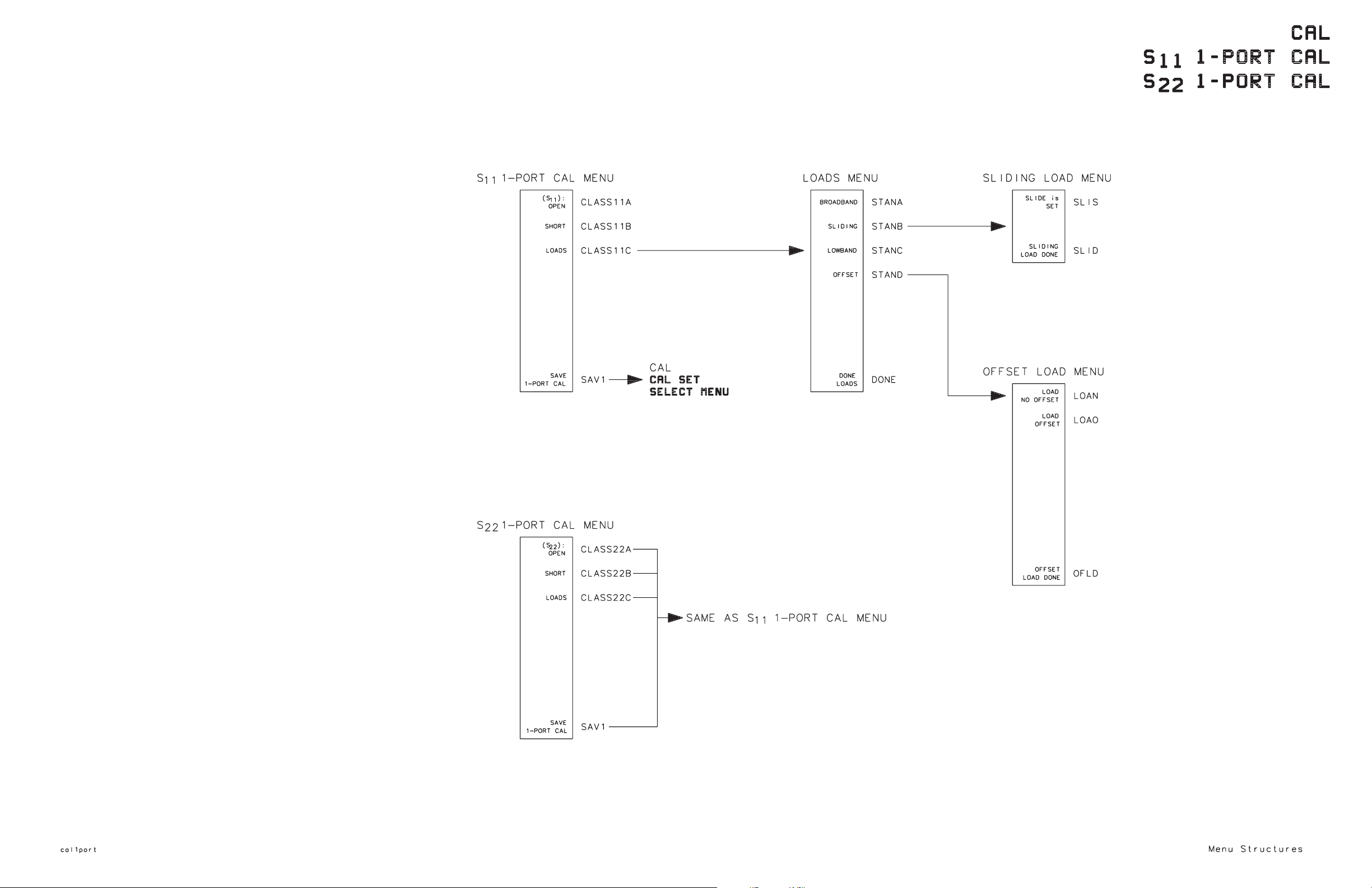
15/16

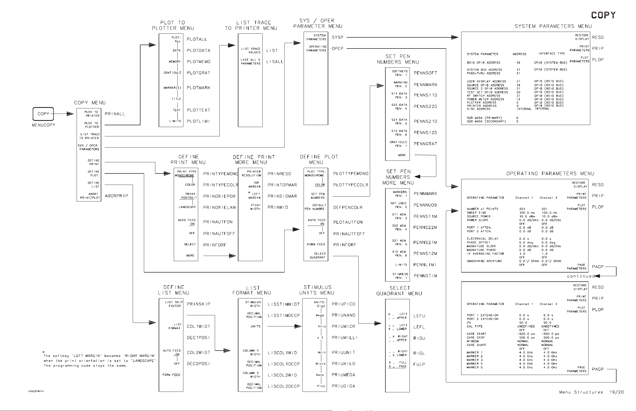


domain


FRONT PANEL
GHZ,NS,NM
MHZ,S,Mµµ
KHZ,MS,MV,MM
HZ,V,M
ofront


marker


Alphabetical List of Programming Codes
Introduction
Use this alphabetical list of the analyzer programming mnemonics as a quick reference to
the syntax requirements and general function of the individual commands. Refer to the
alphabetical reference for more information on the individual entries.
2
Programming Codes 2-1
Notation
Symbols used in this do cument are:
KEYWORD
Upper case characters represent the program keywords that must be used
exactly as shown with no embedded spaces.
[] Square brackets indicate that whatever is enclosed in the bracket is
optional.
[sux] Optional programmer entry units terminator for frequency and time units:
Frequency Sux Time Sux Voltage
GHz fs
MHz ps
kHz ns
Hz us (s)
ms mV
s V
; semicolon is the required terminator character for each program
instruction.
, the comma is used in program instructions to separate a series of
values.
(range of values) lower case text enclosed in parenthesis describes the range of values
whichmay be input for the selected function.
value a constant or a preassigned simple or complex numeric or string
variable transferred to the analyzer.
variable a simple or complex numeric or string variable which receives the value
returned by the analyzer.
(Preset)
Value or state after a network analyzer
NNNNNNNNNNNNNNNNNNNNNNNNNNNNNNNNNNNNNNNNNNNN
FACTORY PRESET
.
2-2 Programming Codes

Example
Example
GATECENT
GATECENT;
GATECENT 1;
GATECENT 1
Once a function is active, it remains active until
selected, and anyvalue input will change its value. For example, sending the string
GHz;
GHz;
[value [time sux]]; Mnemonic may b e written as:
Makes gate center the active function.
Makes gate center the active function, sets gate center
to 1 second. (If no units, default to basic units.)
ns; Makes gate center the active function, sets gate center
to 1 nanosecond.
4
ENTRY OFF
makes start the active function. As long as the function is active, sending the string
will set the start function to 2 GHz.
5
or another active function is
STAR 10
2
Programming Codes 2-3

Alphabetical List of Programming Codes
A
ABORPRIR;
ADAP1;
ADAP2;
ADAR;
ADDR8510
ADDRDISC
ADDRPASS
ADDRPLOT
ADDRPRIN
ADDRPOWE
ADDRRFS
ADDRSOUR
ADDRSOUR2
ADDRSYSB
ADDRTESS
Abort a print or plot output to RS-232 port 1
or 2.
Specify calibration kit containing adapter in
adapter removal modify calibration set.
Select adapter removal mo dify calibration set.
[value]; GPIB address of analyzer (0 to 30).
[value]; Disc unit System bus address (0 to 30).
[value]; System bus address of device to send/receive
data via analyzer system bus GPIB address (0
to 31).
[value]; Digital plotter system bus address (0 to 30).
[value]; Printer system bus address (0 to 30).
[value]; System bus address of power meter (0 to 30).
[value]; System bus address of RF switch for dual test
set switching.
[value]; Source #1 system bus address (0 to 31).
[value]; Source #2 system bus address (0 to 31).
[value]; GPIB address of analyzer system bus (0 to 30).
[value]; Test set system bus address (0 to 31).
ANAOOFF;
ANAOON;
ASEG;
ATTP1
[value]; Port 1 attenuator (0 dB to 90 dB in 10 dB
Analog output o.
Analog output on.
Measure all frequency list segments.
steps).
ATTP2
[value]; Port 2 attenuator. 8514, 8515 only,if
attenuators installed (0 dB to 90 dB in 10 dB
steps).
2-4 Programming Codes

Alphabetical List of Programming Codes
B
AUTD;
Automatic setting of electrical delay to balance
phase.
AUTO;
Automatic selection of
4
REF VALUE
for currentchannel to position trace for
viewing.
AUXV;
Source set to start frequency; measurement
synchronized to aux out. Stimulus controls set
characteristics of digital ramp at AUX OUT
connector.
AVEROFF;
AVERON
[value]; Turn on averaging for selected channel (1 to
Turn o averaging for selected channel (preset).
4096; 1, 2, 4, 8, . . . 4096 sequence).
BACI
[value]; Set the background intensity of the LCD/CRT
(0 to 100).
BEEPOFF;
BEEPON;
Turn caution/warning beep o.
Turn caution/warning beep on (preset).
5
and
4
SCALE
5
C
C0
[value];210
C1
[value];210
C2
[value];210
C3
[value];210
CAL1;
CAL2;
CALF;
CALIFUL2;
CALIONE2;
CALIRAI;
CALIRESP;
CALIS111;
CALIS221;
CALITRL2;
CALK1;
CALK2;
0
15
F
0
27
F/Hz
0
36
F/Hz
0
45
F/Hz
Open circuit capacitance model values.
2
3
Begin measurement calibration using
calibration kit 1.
Begin measurement calibration using
calibration kit 2.
Perform a atness correction calibration
routine.
Select full 2-port calibration.
Select one-part 2-port calibration.
Select response and isolation calibration.
Select response calibration.
Select S111-port calibration.
Select S
1-port calibration.
22
Select TRL 2-port calibration.
Calibration kit data type under
Calibration kit 2 data type under
4
TAPE
4
TAPE
5/4
DISC
5/4
DISC
5
.
5
.
Programming Codes 2-5
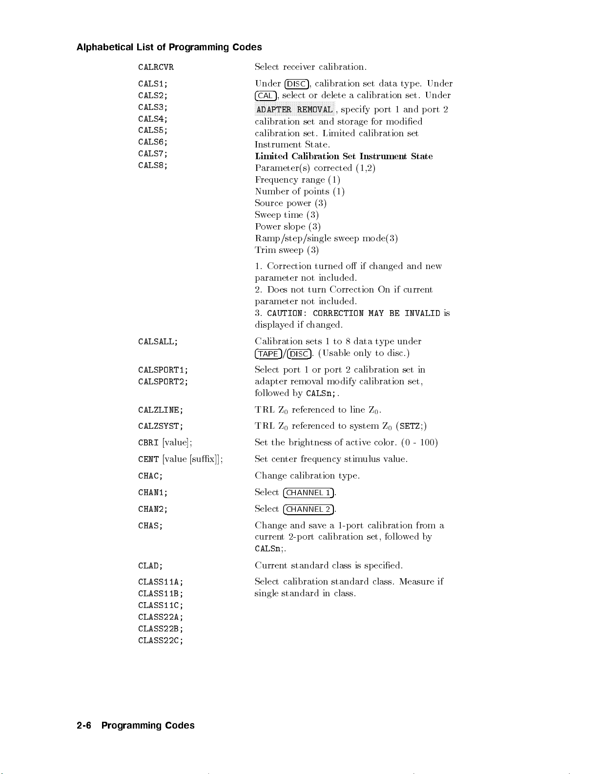
Alphabetical List of Programming Codes
CALRCVR
CALS1;
CALS2;
CALS3;
CALS4;
CALS5;
CALS6;
CALS7;
CALS8;
CALSALL;
CALSPORT1;
CALSPORT2;
Select receiver calibration.
Under
4
NNNNNNNNNNNNNNNNNNNNNNNNNNNNNNNNNNNNNNNNNNN
4
5
, calibration set data type. Under
DISC
5
, select or delete a calibration set. Under
CAL
ADAPTER REMOVAL
, specify p ort 1 and port 2
calibration set and storage for modied
calibration set. Limited calibration set
Instrument State.
Limited Calibration Set Instrument State
Parameter(s) corrected (1,2)
Frequency range (1)
Number of points (1)
Source power (3)
Sweep time (3)
Power slop e (3)
Ramp/step/single sweep mode(3)
Trim sweep (3)
1. Correction turned o if changed and new
parameter not included.
2. Does not turn Correction On if current
parameter not included.
3.
CAUTION: CORRECTION MAY BE INVALID
displayed if changed.
Calibration sets 1 to 8 data type under
4
TAPE
5/4
5
. (Usable only to disc.)
DISC
Select port 1 or port 2 calibration set in
adapter removal modify calibration set,
followed by
CALSn;
.
is
CALZLINE;
CALZSYST;
CBRI
[value]; Set the brightness of active color. (0 - 100)
CENT
[value [sux]]; Set center frequency stimulus value.
CHAC;
CHAN1;
CHAN2;
CHAS;
TRL Z
TRL Z
referenced to line Z0.
0
referenced to system Z0(
0
Change calibration type.
Select
Select
4
CHANNEL 1
4
CHANNEL 2
5
.
5
.
Change and save a 1-port calibration from a
current 2-p ort calibration set, followed by
CALSn
;.
CLAD;
CLASS11A;
CLASS11B;
Current standard class is specied.
Select calibration standard class. Measure if
single standard in class.
CLASS11C;
CLASS22A;
CLASS22B;
CLASS22C;
SETZ
;)
2-6 Programming Codes
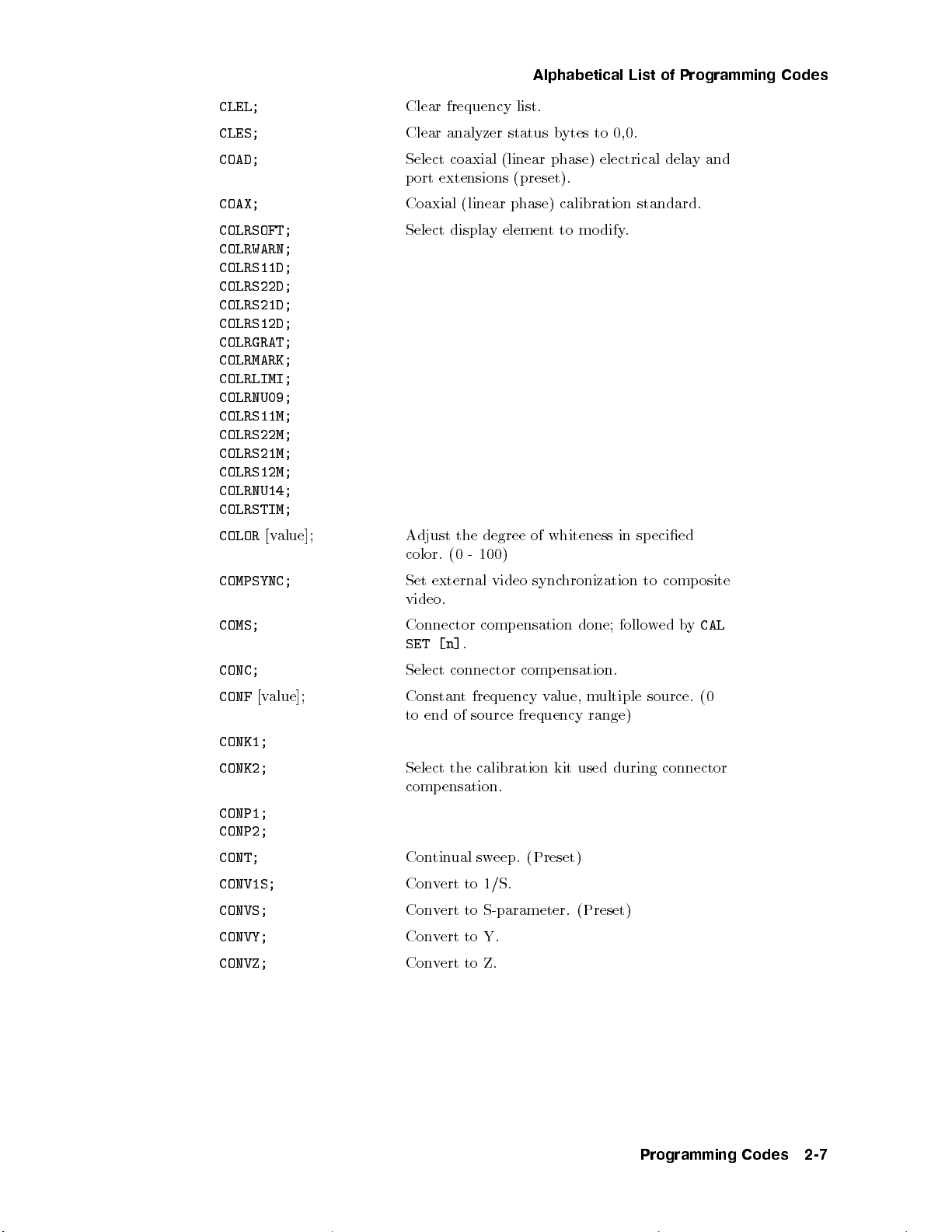
Alphabetical List of Programming Codes
CLEL;
CLES;
COAD;
Clear frequency list.
Clear analyzer status bytes to 0,0.
Select coaxial (linear phase) electrical delay and
port extensions (preset).
COAX;
COLRSOFT;
Coaxial (linear phase) calibration standard.
Select display element to modify.
COLRWARN;
COLRS11D;
COLRS22D;
COLRS21D;
COLRS12D;
COLRGRAT;
COLRMARK;
COLRLIMI;
COLRNU09;
COLRS11M;
COLRS22M;
COLRS21M;
COLRS12M;
COLRNU14;
COLRSTIM;
COLOR
[value]; Adjust the degree of whiteness in specied
color. (0 - 100)
COMPSYNC;
Set external video synchronization to comp osite
video.
COMS;
CONC;
CONF
[value]; Constant frequency value, multiple source. (0
Connector comp ensation done; followed by
SET [n]
.
Select connector compensation.
to end of source frequency range)
CONK1;
CONK2;
Select the calibration kit used during connector
compensation.
CONP1;
CONP2;
CONT;
CONV1S;
CONVS;
CONVY;
CONVZ;
Continual sweep. (Preset)
Convert to 1/S.
Convert to S-parameter. (Preset)
Convert to Y.
Convert to Z.
CAL
Programming Codes 2-7
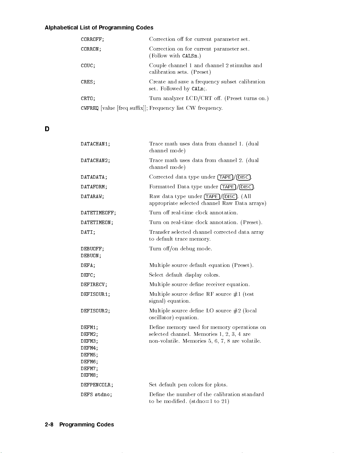
Alphabetical List of Programming Codes
D
CORROFF;
CORRON;
COUC;
CRES;
CRTO;
CWFREQ
[value [freq sux]]; Frequency list CW frequency.
DATACHAN1;
DATACHAN2;
DATADATA;
DATAFORM;
DATARAW;
DATETIMEOFF;
Correction o for current parameter set.
Correction on for current parameter set.
(Follow with
CALSn
.)
Couple channel 1 and channel 2 stimulus and
calibration sets. (Preset)
Create and save a frequency subset calibration
set. Followed by
CALn
;.
Turn analyzer LCD/CRT o. (Preset turns on.)
Trace math uses data from channel 1. (dual
channel mo de)
Trace math uses data from channel 2. (dual
channel mo de)
Corrected data type under
Formatted Data type under
Raw data type under
4
TAPE
4
TAPE
4
TAPE
5/4
DISC
5/4
5/4
DISC
DISC
5
. (All
5
.
5
.
appropriate selected channel Raw Data arrays)
Turn o real-time clock annotation.
DATETIMEON;
DATI;
DEBUOFF;
DEBUON;
DEFA;
DEFC;
DEFIRECV;
DEFISOUR1;
DEFISOUR2;
DEFM1;
DEFM2;
DEFM3;
DEFM4;
DEFM5;
DEFM6;
DEFM7;
DEFM8;
DEFPENCOLR;
Turn on real-time clock annotation. (Preset).
Transfer selected channel corrected data array
to default trace memory.
Turn o/on debug mode.
Multiple source default equation (Preset).
Select default display colors.
Multiple source dene receiver equation.
Multiple source dene RF source #1 (test
signal) equation.
Multiple source dene LO source #2 (local
oscillator) equation.
Dene memory used for memory operations on
selected channel. Memories 1, 2, 3, 4 are
non-volatile. Memories 5, 6, 7, 8 are volatile.
Set default pen colors for plots.
DEFS stdno;
2-8 Programming Codes
Dene the number of the calibration standard
to be mo died. (stdno=1 to 21)

Alphabetical List of Programming Codes
DELA;
DELC;
DELE;
DELO;
DELR1;
DELR2;
DELR3;
DELR4;
DELR5;
DELT;
DENOA1;
DENOA2;
DENOB1;
DENONOR;
DETENORB;
DETEWIDB;
DIRE;
DISCUNIT
Delay format.
Delete calibration set, followed by
CALSn
.
Delete tap e/kdiscle, followed by data type and
FILEn
.
1 mo de o.
Select 1 Ref = delta mode reference marker.
Delay table data type under
a
1
a
2
b
1
b
2
Select denominator for current parameter.
4
TAPE
5/4
DISC
Select the 10 kHz IF path and detectors.
Select the 3 MHz IF bandwidth path and
detectors. Pulsed-RF applications.
Display directory for current tape cartridge or
disc.
[value]; Disc unit number under disc setup. Usually 0
(left drive); 1 (right drive).
5
.
DISCVOL
DISF
[value]; Disc volume number under disc setup.
'lename'; Delete disc lename. Load disc lename.
Store/replace disc lename. Select data type
lename under disc store/load/delete
operations. Seven characters. Do not include
lename data type prex.
DISPDATA;
DISPDATM;
DISPMATH;
DISPMEMO;
DIVI;
DONE;
Display current data only.
Display current data and memory.
Display current data with math.
Display memory only.
Select complex divide trace math.
Current standard class done during
measurement calibration.
DOWN;
Decrease current active function one step.
Programming Codes 2-9

Alphabetical List of Programming Codes
DRIVNONE;
Select drive port for current parameter.
DRIVPORT1;
DRIVPORT2;
DUPD;
DUPM;
Frequency list delete duplicate points.
Frequency list measure duplicate p oints.
(Preset)
DUTC
[value]; Set the duty cycle of the internally generated
trigger. Wideband IF option 008 only (0 to
100).
DWET
[value [time sux]]; Set the dwell time of frequency points in a
frequency list (0 s to 10 s).
E
EDITDONE;
EDITLIST;
EDITMULS;
ELED
[value [time sux]]; Set electrical delay for current parameter on
ENTO;
EXTTOFF;
Edit frequency list done.
Edit frequency list.
Edit multiple source equations.
selected channel. (See
COAD
; and
Entry o.
Select internal trigger.
WAVD
;)
EXTTPOIN;
EQUA;
Select external measurement trigger.
Set current active function equal to current
active marker value.
F
2-10 Programming Codes

Alphabetical List of Programming Codes
FACTPRES;
FASC;
FILE1;
FILE2;
FILE3;
FILE4;
FILE5;
FILE6;
FILE7;
FILE8;
FIRP;
FIXE;
FLATOFF;
FLATON;
FORM1;
FORM2;
Execute a factory preset.
Select fast CW data aquisition (externally
triggered).
Select data type le number under
4
TAPE
5/4
5
store/load/delete op erations.
DISC
First page of tape directory and operating
parameters.
Dene load standard type as xed.
Turn o atness correction calibration. (Preset)
Enable atness correction calibration.
8510C internal binary (6 bytes/point).
IEEE 32 bit fp (8 bytes/point).
Programming Codes 2-11

Alphabetical List of Programming Codes
FORM3;
FORM4;
IEEE 64 bit fp (16 bytes/point).
FORMAT OFF
DIM Data(Numb er of p oints,2)
INTEGER Preamble, Size
Output Nwa;\FORM3; OUTPDATA;"
Enter Nwa data;Preamble, Size, Data(*)
FORMAT OFF
Output Nwa;\FORM3;INPUDATA;"
Enter Nwa;Preamble, Size, Data(*)
Preamble=Standard Blo ck Header, #A.
Size=Number of Bytes in Blo ck.
Data(*)=x,y pairs.
ASCII (strings separated by comma).
FORMATON
DIM Data(Numb er of p oints,2)
Output Nwa;\FORM4; OUTPDATA;"
Enter Nwa data; Data(*)
Output Nwa;\FORM4; INPUDATA;";
Enter Nwa; Data(*)
Data(*)=x,y pairs.
Supress CR/LF after Output
FORM5;
FOUPOVER;
FOUPSPLI;
FREM;
FREO;
FREQ;
FRER;
FRES;
FREU;
FULP;
FWDI;
FWDM;
FWDT;
MS-DOS 32 bit fp (8 bytes/point).
Select four parameter overlay display format.
Select four parameter split display format.
Selects operating frequency in power domain.
Turn o display of frequency values. Turn on
NNNNNNNNNNNNNNNNNNNNNNNNNNNNNNNNNNNNNNNN
by
FACTORY PRESET
or recall Instrument State.
Select Frequency Domain.
Free-run selected sweep mo de. (Preset)
Begin creation of frequency subset, under
modify calibration set.
Update frequency annotation with no sweep.
Select full page plot.
Measure forward isolation standard.
Measure forward match standard.
Measure forward transmission standard.
2-12 Programming Codes

G
Alphabetical List of Programming Codes
H
GAIN0;
GAIN1;
GAIN2;
GAIN3;
GAIN4;
GAINAUTO;
GATECENT
GATEOFF;
GATEON;
GATESPAN
GATESTAR
GATESTOP
GATSMAXI;
GATSMINI;
GATSNORM;
GATSWIDE;
GREESYNC;
Service only. Select ref or test IF gain.
(Preset)
[value [time sux]]; Set gate center.
Turn o time domain gating.
Turn on time domain gating. Display Time
Domain gate markers.
[value [time sux]]; Set gate span.
[value [time sux]]; Set gate start.
[value [time sux]]; Set gate stop.
Select gate shape.
External video set to synchronize on green.
HARS;
Hardware State data type under
4
TAPE
5/4
DISC
5
.
Complete multiple source Hardware State and
GPIB addresses.
HOLD;
HVSYNC;
Hold mode; sweep stopped.
External video set to synchronize on horizontal
and vertical.
I
Programming Codes 2-13

Alphabetical List of Programming Codes
IMAG;
INID;
INIT;
INPUCALC01;
INPUCALC02;
INPUCALC03;
INPUCALC04;
INPUCALC05;
INPUCALC06;
INPUCALC07;
INPUCALC08;
INPUCALC09;
INPUCALC10;
INPUCALC11;
INPUCALC12;
INPUDATA;
INPUDELA;
INPUFORM;
INPUFREL;
Imaginary Cartesian format.
Begin disc initialization.
Begin tape initialization.
Store measurement calibration error coecient
set real/imaginary pairs input via GPIB into
analyzer memory. Select appropriate
calibration type, input necessary co ecient sets
(see
OUTPCALCn
save in a calibration set. Issue
), then issue
SAVC; CALSn;
CORRON; CALSn;
to
to turn correction ON.
Store selected channel corrected data trace
memory real/imaginary pairs input via GPIB.
To input to memory,
INPUDATA; DATI;
.
Input delay table real/imaginary pairs for
selected channel via GPIB.
Store selected channel formatted trace memory
input via GPIB.
Cartesian: x = basic units.
Cartesian: y = 0.
Polar and Smith: real/imaginary pairs.
Input frequency list via GPIB.
INPULEAS;
INPURAW1;
INPURAW2;
INPURAW3;
INPURAW4;
INSS1;
INSS2;
INSS3;
INSS4;
INSS5;
INSS6;
INSS7;
INSS8;
Store FORM1 analyzer Learn String, previously
output by
OUTPLEAS
, input via GPIB. Set
analyzer to Learn String state.
Store selected channel Raw Data trace memory
real/imaginary pairs input via GPIB. (See
OUTPRAWn
)
Single Instrument State data type under
4
TAPE
5/4
DISC
5
.
2-14 Programming Codes

Alphabetical List of Programming Codes
K
L
INSSALL;
INTE
[value]; Select the intensity level of the display(0 to
INVS;
ISOD;
ISOL;
KEYC
value; Press analyzer front panel key. See
KITD;
All Instruments States 1-8 data type.
100).
Inverted Smith chart format.
2-port isolation done.
Begin 2-port isolation calibration.
Kit done (mo died). Store current calibration
kit denition.
OUTPKEY
.
Programming Codes 2-15

Alphabetical List of Programming Codes
0
L0
[value];210
L1
[value];210
L2
[value];210
L3
[value];210
0
0
0
12
24
33
42
H
H/Hz
H/Hz
H/Hz
2
3
Short circuit inductance model values.
LABEADAP
LABEFWDI
LABEFWDM
LABEFWDT
LABERESP
LABEREVI
LABEREVM
LABEREVT
LABES11A
LABES11B
LABES11C
LABES22A
LABES22B
LABES22C
LABETRLL
LABETRLR
LABETRLT
LABK
[\string"];
[\string"];
[\string"];
Up to ten character standard class lab el.
Standard class label is displayed only when
more than one standard in class.
[\string"];
[\string"];
[\string"];
[\string"];
[\string"];
[\string"];
[\string"];
[\string"];
[\string"];
[\string"];
[\string"];
[\string"];
[\string"];
[\string"];
[\string"]; Label kit. Up to ten character lab el for current
calibration kit.
LABS
[\string"]; Label standard. Up to ten character lab el for
current calibration standard.
LASP;
LEFL;
LEFU;
Last page of tape directory.
Left lower plot.
Left upper plot.
LIMIADDLMAX;
LIMIADDLMIN;
LIMIADDPMAX;
Add a limit line to dene maximum valid data.
Add a limit line to dene minimum valid data.
Add a limit point to dene maximum valid
data.
2-16 Programming Codes

Alphabetical List of Programming Codes
LIMIADDPMIN;
LIMIBEGLIM;
LIMIBEGSTIM;
LIMIDELALL;
LIMIDELSEG;
LIMIEDITSEG
[sux]];
LIMIENDLIM
[sux]];
LIMIENDSTIM
[sux]];
LIMILINEOFF;
LIMILINEON;
LIMITESTOFF;
LIMITESTON;
Add a limit point to dene minimum valid
data.
Set the measurementvalue of the beginning of
a limit segment.
Set the stimulus value of the beginning of a
limit segment.
Remove all entries from a limit line table.
Removean entry from a limit line table.
[segmentnumber
[measurementvalue
[measurementvalue
Turn o the display of all limit lines and
points.
Turn on the display of all limit lines and
points.
Turn o testing for data that violates limits.
Turn on testing for data that violates limits.
Edit limit point or limit line
segment table entry.
Set the measurementvalue of the
end of a limit segment.
Set the stimulus value of the end
of a limit segment.
LINM;
LINP;
LISALL;
LISAUTFOFF;
LISAUTFON;
LISFORF;
LISFREQ;
LISSKIP
[value]; Set the skip factor of a printed frequency list.
LIST;
LISCOL1DECP
LISCOL2DECP
LISCOL1WID
LISCOL2WID
Linear magnitude Cartesian format.
Linear marker on Polar format.
List all S-parameters for the selected channel
to a printer.
Turn o the automatic pap er feed on a prin
for listing S-parameters.
Turn on the automatic pap er feed on a prin
for listing S-parameters. (Preset)
Immediately eject a page from a printer.
Select frequency list sweep mode.
(1 to 401, 4 = Preset)
List trace values to printer.
[value]; Set the number of digits after the decimal
point in column 1 data. (1 to 15, 2 = Preset)
[value]; Set the number of digits after the decimal
point in column 2 data. (1 to 15, 2 = Preset)
[value]; Set the total number of characters printed in
column 1. (1 to 15, 10 = Preset)
[value]; Set the total number of characters printed in
column 2. (1 to 31, 10 = Preset)
ter
ter
Programming Codes 2-17
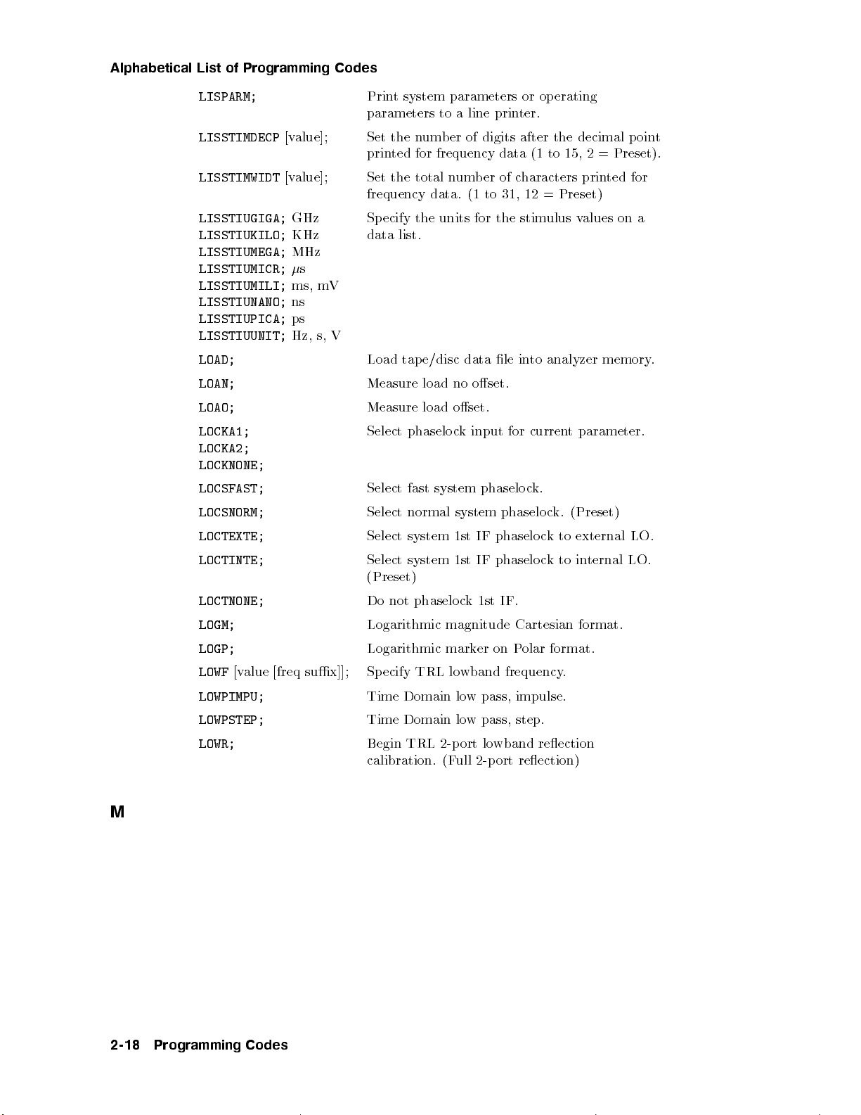
Alphabetical List of Programming Codes
LISPARM;
LISSTIMDECP
LISSTIMWIDT
LISSTIUGIGA;
LISSTIUKILO;
LISSTIUMEGA;
[value]; Set the number of digits after the decimal point
[value]; Set the total number of characters printed for
GHz
KHz
MHz
LISSTIUMICR;s
LISSTIUMILI;
LISSTIUNANO;
LISSTIUPICA;
LISSTIUUNIT;
ms, mV
ns
ps
Hz, s, V
LOAD;
LOAN;
LOAO;
LOCKA1;
LOCKA2;
LOCKNONE;
LOCSFAST;
Print system parameters or operating
parameters to a line printer.
printed for frequency data (1 to 15, 2 = Preset).
frequency data. (1 to 31, 12 = Preset)
Specify the units for the stimulus values on a
data list.
Load tape/disc data le into analyzer memory.
Measure load no oset.
Measure load oset.
Select phaselock input for current parameter.
Select fast system phaselock.
M
LOCSNORM;
LOCTEXTE;
LOCTINTE;
Select normal system phaselock. (Preset)
Select system 1st IF phaselo ck to external LO.
Select system 1st IF phaselo cktointernal LO.
(Preset)
LOCTNONE;
LOGM;
LOGP;
LOWF
[value [freq sux]]; Specify TRL lowband frequency.
LOWPIMPU;
LOWPSTEP;
LOWR;
Do not phaselock 1st IF.
Logarithmic magnitude Cartesian format.
Logarithmic marker on Polar format.
Time Domain low pass, impulse.
Time Domain low pass, step.
Begin TRL 2-port lowband reection
calibration. (Full 2-port reection)
2-18 Programming Codes

Alphabetical List of Programming Codes
MACD;
Machine dump data type under
4
TAPE
Complete instrument state and all memories.
(Usable only to disc).
MAGO
[value]; Set magnitude oset, dB, for current parameter
on selected channel.
MAGS
[value]; Set magnitude slope, dB/GHz, for current
parameter on selected channel.
MARK1
[value [sux]];
MARK2
[value [sux]];
MARK3
[value [sux]];
MARK4
[value [sux]];
MARK5
[value [sux]];
MARKCONT;
Select active marker and move it to sp ecied
stimulus value.
Continuous markers (linear intepolation
between measured points).
MARKDISC;
Discrete markers (only measured points).
(Preset)
MARKMAXI;
MARKMINI;
MARKOFF;
MARKTARG;
Active marker to maximum trace value.
Active marker to minimum trace value.
Turn all markers o.
Active marker to target trace value. (Search
starts from lowest stimulus value.)
5/4
DISC
5
.
MAXF
[value [freq sux]]; Maximum frequency of current calibration
standard.
MEMO1;
Trace memory data type under
MEMO2;
MEMO3;
MEMO4;
MEMO5;
MEMO6;
MEMO7;
MEMO8;
MEMOALL;
MENUCAL;
MENUCOPY;
MENUDISC
MENUDISP;
Present
Present
Present
Present
4
5
CAL
4
COPY
4
5
DISC
4
DISPLAY
menu.
5
menu.
menu.
5
menu.
4
TAPE
5/4
DISC
5
.
Programming Codes 2-19

Alphabetical List of Programming Codes
MENUDOMA;
MENUFORM;
MENUMARK;
MENUOFF;
MENUON;
MENUPARA;
MENUPRIO;
MENURECA;
MENURESP;
MENUSAVE;
MENUSTIM;
MENUSYST;
MENUTAPE;
MENUTEST;
MINF
[value [freq sux]]; Minimum frequency of current calibration
Present
Present
Present
4
DOMAIN
4
FORMAT
4
MARKER
5
menu.
5
menu.
5
menu.
Turn o display of menus.
Turn on normal display of menus.
Present
Present
Present
Present
Present
Present
Present
Present
4
PARAMENTER
4
5
5
menu.
menu.
5
menu
5
5
5
menu.
PRIOR
4
RECALL
4
RESPONSE
4
SAVE
4
STIMULUS
4
SYSTEM
4
TAPE/DISC
5
menu.
menu.
5
menu.
menu.
Present test menu. (GPIB activity suspended.)
standard. (Fcofor waveguide type.)
MINU;
Minus. Complex subtraction trace math for
selected channel.
MKRLFIVM;
MKRLFOUP;
Select 5 marker display list.
Select marker list for four parameter display,
the active marker p er parameter.
MKRLISTOFF;
MKRLISTON;
MODI1;
MODI2;
MODS;
MONI;
Turn the marker list o.
Turn the marker list on. (Preset)
Modify 1 (calibration kit 1 lab el).
Modify 2 (calibration kit 2 lab el).
Modify selected calibration sets and save, follow
with
CALSn;
.
For Service Use Only. (TEST or cycle LINE
power to exit)
MULD
[value]; Multiple source multipler denominator.
MULN
[value]; Multiple source multiplier numerator.
MULSOFF;
Turn o multiple source and saveinto hardware
state.
MULSON;
Turn on multiple source and saveinto hardware
state.
MULT;
Multiply. Complex multiplication trace math
for selected channel.
2-20 Programming Codes
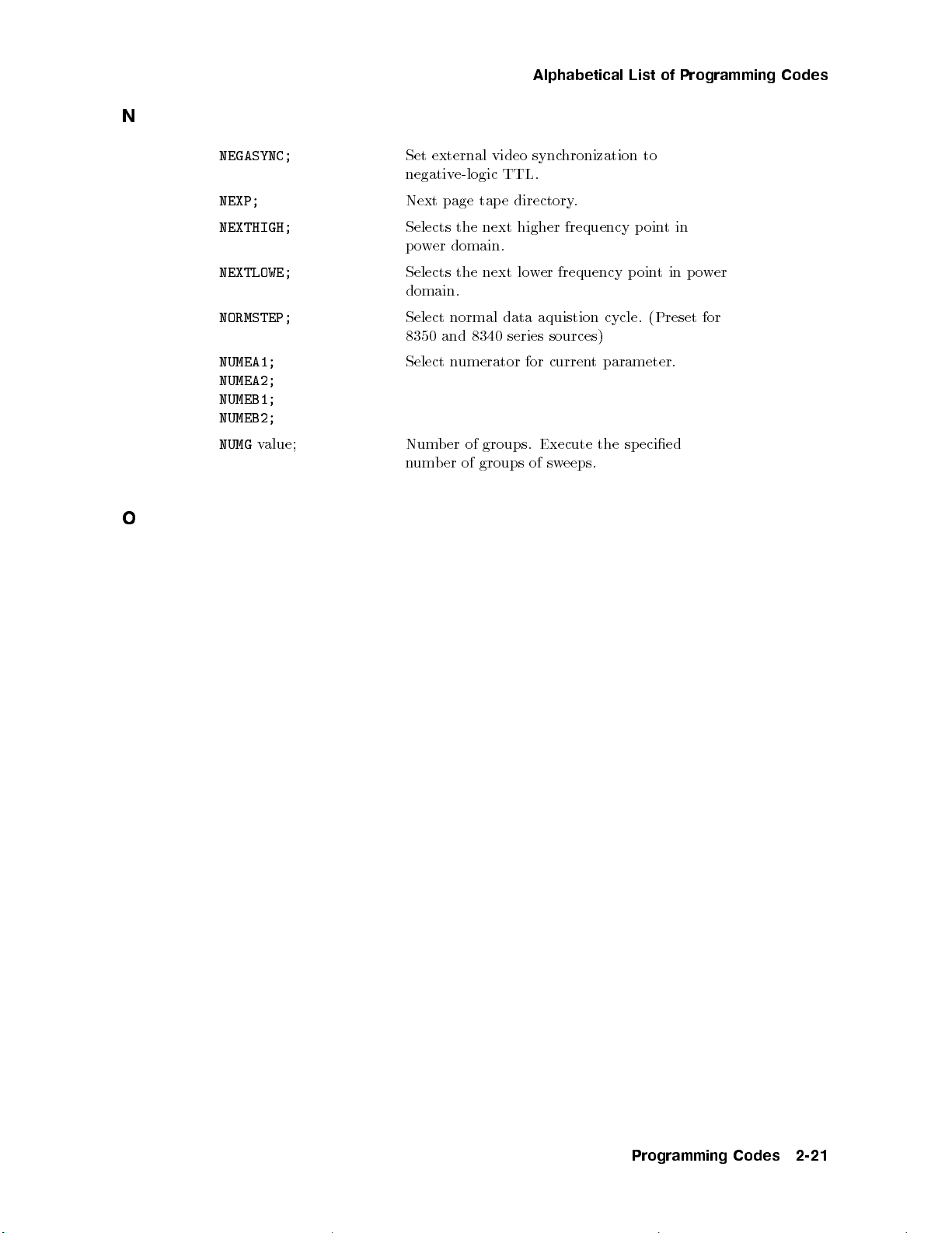
N
Alphabetical List of Programming Codes
O
NEGASYNC;
NEXP;
NEXTHIGH;
NEXTLOWE;
NORMSTEP;
NUMEA1;
NUMEA2;
NUMEB1;
NUMEB2;
NUMG
value; Number of groups. Execute the specied
Set external video synchronization to
negative-logic TTL.
Next page tape directory.
Selects the next higher frequency pointin
power domain.
Selects the next lower frequency pointinpower
domain.
Select normal data aquistion cycle. (Preset for
8350 and 8340 series sources)
Select numerator for current parameter.
number of groups of sw
eeps.
Programming Codes 2-21
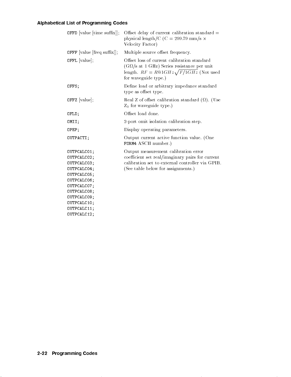
Alphabetical List of Programming Codes
OFFD
[value [time sux]]; Oset delay of current calibration standard =
OFFF
[value [freq sux]]; Multiple source oset frequency.
OFFL
[value]; Oset loss of current calibration standard
physical length/C (C = 299.79 mm/s
2
VelocityFactor)
(G/s at 1 GHz) Series resistance per unit
length.
RF=R@1GH zpF=1GH z
(Not used
for waveguide type.)
OFFS;
Dene load or arbitrary imp edance standard
type as oset type.
OFFZ
[value]; Real Z of oset calibration standard (). (Use
Z0for waveguide type.)
OFLD;
OMII;
OPEP;
OUTPACTI;
OUTPCALC01;
OUTPCALC02;
OUTPCALC03;
OUTPCALC04;
Oset load done.
2-port omit isolation calibration step.
Display operating parameters.
Output current active function value. (One
FORM4
ASCII number.)
Output measurement calibration error
coecient set real/imaginary pairs for current
calibration set to external controller via GPIB.
(See table below for assignments.)
OUTPCALC05;
OUTPCALC06;
OUTPCALC07;
OUTPCALC08;
OUTPCALC09;
OUTPCALC10;
OUTPCALC11;
OUTPCALC12;
2-22 Programming Codes

Alphabetical List of Programming Codes
OUTPDATA;
OUTPDELA;
OUTPERRO;
OUTPFORM;
OUTPFREL;
OUTPIDEN;
OUTPKEY;
OUTPLEAS;
OUTPMARK;
Output selected channel corrected data array
real/imaginary pairs.
Output delay table real/imaginary pairs.
Output number and message of current
caution/tell message to external controller, clear
status bytes, clear caution/tell message, no
change to Status Request Mask. (See SRQM.)
Output selected channel formatted data array
pairs.
Cartesian: x = basic units of selected format, y
=0.
Polar and Smith: real/imaginary pairs.
Output frequency list.
Output analyzer identication ASCI I string.
(Same string as displayed for
SOFR;
)
Output integer number for last key pressed.
(See \Alphabetical Reference.")
Output 4390-byte
FORM1
analyzer Learn String.
(Same contents as Instrument State.)
Output active marker trace value. (Two
FORM4
ASCII numbers.)
OUTPMEMO;
Output currently selected trace memory
real/imaginary pairs.
OUTPPLOT;
Output complete screen including menuas
variable-length HPGL strings to analyzer
GPIB.
OUTPRAW1;
OUTPRAW2;
Output trace data from currently selected
channel Raw Data array real/imaginary pairs.
OUTPRAW3;
OUTPRAW4;
OUTPSTAT;
Output analyzer Status Bytes (2 ASCII
integers), and clear Status Bytes. (See SQRM.)
OUTPTITL;
Output current active title, calibration kit
label, standard lab el, standard class label or
standards in class. ASCII string.
OVER;
Dual channel overlay display.
P
Programming Codes 2-23

Alphabetical List of Programming Codes
PAGP;
Page parameters. Display next page of
operating parameters list.
PARL
[\string"]; Parameter label. Label current user parameter
using up to eightcharacters. (User parameters
only.)
PEEK;
Examine contents of memory specied by
peek/poke location. Active function is contents
of specied memory location. Service Use Only.
PEEL
memory address; Peek/poke location. Sp ecify peek and poke
memory address. Service Use Only.
PEN1;
PEN2;
Select pen for current plot type for selected
channel.
PEN3;
PEN4;
PEN5;
PEN6;
PEN7;
PEN8;
PENNMONO;
PENNSOFT;
PENNWARN;
Monochromatic p en selection.
Select pen colors for the various display
elements to plot to a color plotter.
PENNS11D;
PENNS22D;
PENNS21D;
PENNS12D;
PENNGRAT;
PENNMARK;
PENNNU09;
PENNS11M;
PENNS22M;
PENNS21M;
PENNS12M;
PENNNU14;
PENNSTIM;
PHAO
[value]; Phase oset for current parameter on selected
PHAS;
PLOP;
PLOT4S;
PLOTALL;
PLOTAUTFOFF;
PLOTAUTFON;
PLOTDATA;
PLOTFORF;
2-24 Programming Codes
channel.
Phase Cartesian format.
Plot current page of operating parameters
listing using digital plotter.
Plot all four S-parameters using a digital
plotter.
Plot complete measurement display including
user display using digital plotter.
Turn o the automatic pap er feed on a plotter.
Turn on the automatic pap er feed on a plotter.
Plot trace data only using a digital plotter.
Immediately eject a page from a plotter.
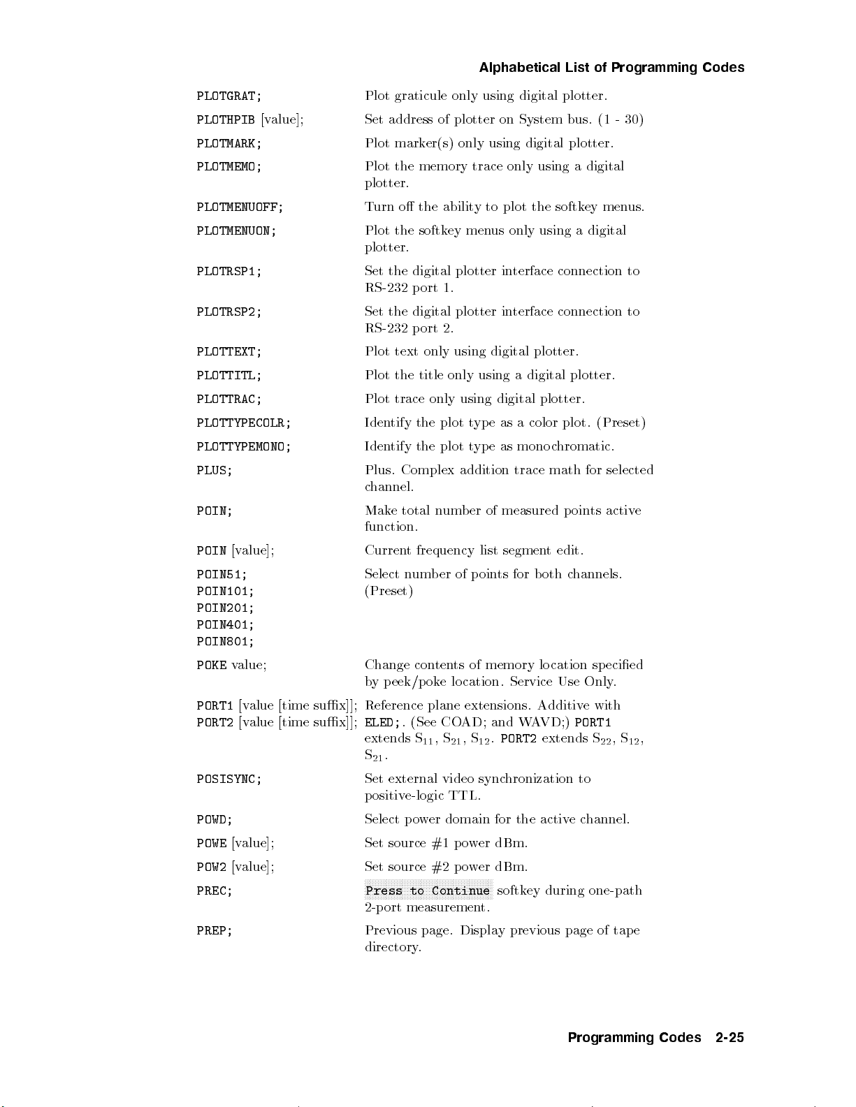
Alphabetical List of Programming Codes
PLOTGRAT;
PLOTHPIB
[value]; Set address of plotter on System bus. (1 - 30)
PLOTMARK;
PLOTMEMO;
PLOTMENUOFF;
PLOTMENUON;
PLOTRSP1;
PLOTRSP2;
PLOTTEXT;
PLOTTITL;
PLOTTRAC;
PLOTTYPECOLR;
PLOTTYPEMONO;
PLUS;
Plot graticule only using digital plotter.
Plot marker(s) only using digital plotter.
Plot the memory trace only using a digital
plotter.
Turn o the ability to plot the softkey menus.
Plot the softkey menus only using a digital
plotter.
Set the digital plotter interface connection to
RS-232 p ort 1.
Set the digital plotter interface connection to
RS-232 p ort 2.
Plot text only using digital plotter.
Plot the title only using a digital plotter.
Plot trace only using digital plotter.
Identify the plot type as a color plot. (Preset)
Identify the plot type as mono chromatic.
Plus. Complex addition trace math for selected
channel.
POIN;
Make total number of measured points active
function.
POIN
[value]; Current frequency list segment edit.
POIN51;
POIN101;
Select number of points for both channels.
(Preset)
POIN201;
POIN401;
POIN801;
POKE
value; Change contents of memory location specied
by peek/poke location. Service Use Only.
PORT1
[value [time sux]];
PORT2
[value [time sux]];
Reference plane extensions. Additive with
ELED;
. (See COAD; and WAVD;)
extends S11,S21,S12.
PORT2
extends S22,S12,
S21.
POSISYNC;
Set external video synchronization to
positive-logic TTL.
POWD;
POWE
[value]; Set source #1 power dBm.
POW2
[value]; Set source #2 power dBm.
Select power domain for the activechannel.
NNNNNNNNNNNNNNNNNNNNNNNNNNNNNNNNNNNNNNNNNNNNNNNN
PREC;
Press to Continue
softkey during one-path
2-port measurement.
PREP;
Previous page. Display previous page of tap e
directory.
PORT1
Programming Codes 2-25

Alphabetical List of Programming Codes
PRES;
PRINALL;
PRINAUTFOFF;
PRINAUTFON;
PRINFORF;
PRINHPIB
[value]; Set address of printer on system bus (1 to 31).
PRINMENUOFF;
PRINMENUON;
PRINORIELAN;
PRINORIEPOR;
PRINRESO
[value]; Set the printer resolution in dots per inch(0to
PRINRSP1;
PRINRSP2;
Preset.
Print the complete plot to a graphics printer.
Turn automatic form feed o in a graphics
printer.
Turn automatic form feed on in a graphics
printer. (Preset)
Immediately eject a page from a graphics
printer.
Turn o the ability to print the softkey menus
using a graphics printer.
Print the softkey menus using a graphics
printer.
Set the graphics printer page orientation to
landscape.
Set the graphics printer orientation to portrait
(preset).
400, 96 = Preset).
Set the graphics printer interface connection to
RS-232 p ort 1.
Set the graphics printer interface connection to
RS-232 p ort 2.
PRINSIDMAR [value];
Set either left or right margin distance of
printer plots. Left margin set in p ortrait
orientation, right margin set in landscape
orientation (0 to 1.0 m).
PRINTOPMAR [value];
Set top margin distance for printer plots (0 to
1.0 m).
PRINTYPECOLR;
Dene the printtype as a plot dump to a color
printer.
PRINTYPEMONO;
Dene the printtype as a plot dump to a single
color printer.
PRINWID [value];
Set the total width of a printed plot (0 to 1.0
m).
PRIP;
Print parameters. Print current page of
operating or system parameters using printer.
PULOHIGH;
PULOLOW;
PULP;
PULW
[value [time sux]]; Set width of internally generated pulse.
Set pulse output active high.
Set pulse output activelow.
Select pulse prole domain.
Wideband option 008 only. (0 ms to 40.88 ms)
2-26 Programming Codes

Q
Alphabetical List of Programming Codes
R
QUICSTEP;
RAID;
RAIRESP;
RAIISOL;
RAMP;
RCVI;
RCVK1;
RCVK2;
RCVO;
REAL;
RECA1;
RECA2;
RECA3;
RECA4;
RECA5;
RECA6;
RECA7;
RECA8;
RECO;
Select the quick step phaselock mode.
Response and isolation calibration done,
followed by
CALSn;
.
Measure response standard in response and
isolation calibration.
Measure isolation standard in response and
isolation calibration.
Ramp sweep mode.
Measure receiver input power.
Specify calibration kit to be used for THRUin
receiver calibration.
Select receiver output power; measure if single
standard in THRU class.
Real Cartesian format.
Recall previously stored Instrument State from
specied internal memory. (Restores standard
Basic parameter denitions; selects
DISPDATA;
Recall previously saved LCD/CRT colors.
.)
REDD;
Redene done. Store current parameter
denition.
REFA;
REFD;
Reference amplier gain. See
Reection done. All 2-port reection standard
classes are measured.
REFL;
Begin 2-port reection measurement calibration
steps.
REFP
[value]; Reference p osition. (0 to 10)
REFV
[value]; Reference value.
REIP;
RESC;
Real/Imaginary on polar format.
Resume calibration at point calibration menu
structure was exited.
RESD;
RESI;
Restore display after
Reset IF correction. Initiate automatic IF gain
calibration; reset timer.
GAINn
DIRE, OPEP
.
,or
SYSP
.
Programming Codes 2-27

Alphabetical List of Programming Codes
REST;
REVI;
REVM;
Measurement restart at beginning of group.
Measure reverse isolation isolation standard.
Begin reverse match measurement calibration
step. Measure if single standard in class.
REVT;
Begin reverse transmission measurement
calibration step. Measure if single standard in
class.
RIGL;
RIGU;
RSCO;
Right lower plot quadrant.
Right upp er plot quadrant.
Set the selected color to the default values.
S
S1;
Select S-parameter on currentchannel.
S12;
S21;
S22;
SADD;
SAV1;
Add a frequency list segment.
Save 1-port measurement calibration; followed
by
CALSn;
.
SAV2;
SAVC;
SAVE1;
SAVE2;
SAVE3;
SAVE4;
SAVE5;
SAVE6;
SAVE7;
SAVE8;
SAVR;
SAVT;
SAVUASCI;
SAVUBINA;
Save full 2-port measurement calibration;
followed by
CALSn;
.
Store calibration coecients loaded using
INPUCALCn
.Followed by
CALSn;
.
Save current Instrument State in specied
internal memory.
Save receiver calibration; follow with
CALSn;
.
Save TRL 2-port measurement calibration;
followed by
CALSn;
.
Select ASCII format for disc operation. (Preset)
Select binary format for disc operation.
2-28 Programming Codes

Alphabetical List of Programming Codes
SCAL
[value]; Scale Y-axis and Polar scale/division.
SDEL
[value]; Delete current or sp ecied frequency list
segment. (value=1-31)
SDON;
Current frequency list segment edit done. If in
frequency list sweep mode, update trace.
SEAL;
Active marker search left from current position
for selected minimum, maximum, or target.
SEAR;
Active marker search right from current
position for selected minimum, maximum, or
target.
SEDI
[value]; Edit current or specied frequency list segment.
SEGM
[value]; Choose frequency list segment to edit.
SERVADCG;
Service Use Only.
SERVDETG;
SERVREFC;
SERVTEMP1;
SERVTEMP2;
SERVTESC;
SERVVCAL;
SERVVREF;
SETDAY
[value]; Set the day of the month for the real-time
clock. (1 to 31)
SETF;
Set frequency low pass. Start/stop frequencies
maychange. Issue once after
Included in
TIML;
.
CAL1;orCAL2;
.
SETHOUR
SETMIN
SETMTH
SETYEAR
[value]; Set the hour part of the real-time clo c
[value]; Set the minutes part of the real-time cloc
[value]; Set the month part of the real-time clock. (1 to
[value]; Set the year part of the real-time clock. (00 to
SETRREFL;
SETRTHRU;
SETZ
[value]; Set Z
k. (0 to
24)
k. (0
to 60)
12)
99)
TRL reection standard sets reference plane.
TRL thru standard sets reference plane.
of Smith Chart, Inverted Smith, load
0
calibration standards, convert to Z and convert
to Y. (Preset selects Z0= 50 .)
Programming Codes 2-29

Alphabetical List of Programming Codes
SIMS;
SINC;
SING;
SINP;
SLID;
SLIL;
SLIS;
SLOPOFF;
SLOP2OFF;
SLOPON
[value]; Set source #1 (RF) power slop e (dB/GHz).
SLOP2ON
SMIC;
SMOOOFF;
In TRIG mo de, with calibration standard
selected, moveRaw Data to calibration
coecient storage. (Simulate measurementof
calibration standard).
Single channel display.
Single sweep. Execute one group of sweeps,
then hold.
Single point mode. Use
4
CENTER
5
to set
frequency.
Sliding load done.
Specify the current standard load calibration
standard as sliding.
Slide is set, measure one slide position. 5 slides
minimum; 6-12 slides recommended.
Source #1 (RF) power slope o.
Source #2 (LO) power slope o.
[value]; Set source #2 (LO) p ower slope (dB/GHz).
Smith Chart format.
Smoothing o for selected channel.
SMOOON
[value]; Smo othing on for selected channel. (Value =
percent of span: 0.1, 0.2, 0.5, . . . 20 sequence.)
Cartesian displays only.
SOFR;
SOFT1;
SOFT2;
Display operating system software revision.
Press soft key. Execute current lab eled
function.
SOFT3;
SOFT4;
SOFT5;
SOFT6;
SOFT7;
SOFT8;
SOU1EXTE;
SOU2EXTE;
SOU1INTE;
SOU2INTE;
SPAN
[value [sux]]; Set stimulus span.
Select source 1 (RF) external leveling.
Select source 2 (LO) external leveling.
Select source 1 (RF) internal leveling.
Select source 2 (LO) internal leveling.
2-30 Programming Codes

Alphabetical List of Programming Codes
SPECADAP
SPECFWDI
SPECFWDM
SPECFWDT
SPECRESP
SPECREVI
SPECREVM
SPECREVT
SPECS11A
SPECS11B
SPECS11C
SPECS22A
SPECS22B
SPECS22C
SPECTRLL
SPECTRLR
SPECTRLT
SPLI;
SRQM
stanAno [, stanBno . . . [, stanGno]];
stanAno [, stanBno . . . [, stanGno]];
stanAno [, stanBno . . . [, stanGno]];
stanAno [, stanBno . . . [, stanGno]];
stanAno [, stanBno . . . [, stanGno]];
stanAno [, stanBno . . . [, stanGno]];
Specify one to seven
standards in each class.
stanAno = stdno of rst
standard in class;
stanGno = stdno of
seventh standard in class.
stanAno [, stanBno . . . [, stanGno]];
stanAno [, stanBno . . . [, stanGno]];
stanAno [, stanBno . . . [, stanGno]];
stanAno [, stanBno . . . [, stanGno]];
stanAno [, stanBno . . . [, stanGno]];
stanAno [, stanBno . . . [, stanGno]];
stanAno [, stanBno . . . [, stanGno]];
stanAno [, stanBno . . . [, stanGno]];
stanAno [, stanBno . . . [, stanGno]];
stanAno [, stanBno . . . [, stanGno]];
stanAno [, stanBno . . . [, stanGno]];
Dual channel split display format.
bytea,byteb; Set SRQ mask. Mask selected bits of the Status
Bytes to enable analyzer SRQ. Mask do esn't
aect
OUTPSTAT
.
bytea = primary status byte, 0-255;
byteb = secondary status byte, 0-255.
SSEG
[value]; Measure single frequency list segment. (value =
segmentnumber)
STANA;
STANB;
Measure calibration standard in class. (See Cal
Kit Standard Class Assignments)
STANC;
STAND;
STANE;
STANF;
STANG;
STAR
[value [sux]]; Set start stimulus value.
STDD;
Standard done (dened). All necessary
characteristics of current standard are dened.
Programming Codes 2-31

Alphabetical List of Programming Codes
STDTARBI;
STDTDELA;
STDTLOAD;
STDTOPEN;
STDTSHOR;
STEP;
STOIDISC;
arbitrary imp edance
delay/thru
load
open
short
Specify current standard type.
Step sweep mode.
Select external disc on system bus for
store/load/delete operations.
STOIEXT;
Select external disc drive for
store/load/delete operations.
STOIINT;
Select the internal disc drive for
store/load/delete operations. (Preset)
STOITAPE;
Select internal tape for store/load/delete
opeations. (Applies to HP 8510B only).
STOP
[value [sux]]; Set stop stimulus value.
STOR;
STPSIZE
[value [freq sux]]; Sp ecify current frequency list segment
Store tape/disc data le.
frequency step size.
SUBSCENT
[value [sux]]; Set frequency subset center frequency,
part of mo dify calibration set.
SUBSSPAN
[value [sux]]; Set frequency subset span value, part of
modify calibration set.
SUBSSTAR
[value [sux]]; Set frequency subset start frequency,
part of mo dify calibration set.
SUBSSTOP
[value [sux]]; Set frequency subset stop frequency, part
of modify calibration set.
SVCO;
Save the current LCD/CRT color
selections in the \user's color" memory
part of the hardware state.
SWET
[value [time sux]]; Set sweep time.
SWR;
SYSBLOCA;
SWR Cartesian format.
Analyzer system bus set to front panel
(local) respose.
SYSBREMO;
Analyzer system bus set to remote
response. (Automatic after 8510
addressed following Pass-Thru; includes
Source Limited Instrument State Recall.)
SYSP;
Display system parameters.
2-32 Programming Codes

Alphabetical List of Programming Codes
T
TABD;
TARV
[value]; Specify current format target value for marker
Use delay table for electrical delay.
to target.
TERI
[value]; Terminal imp edance of arbitrary impedance
type calibration standard (Ohms).
TESA;
TIMB;
Test amplier gain. See
GAINn
.
Time band pass. Time Domain display with no
frequency limitations.
TIML;
Time low pass. Time Domain display with
harmonically related frequencies. (Includes
execution of
TINT
[value]; Set the tint for the color b eing modied. (0 -
SETF;
.)
100)
TITL
[\string"]; Title.
TRAD;
Transmission done. All necessary 2-p ort
transmission and match standard classes are
measured.
TRAN;
Begin 2-port transmission measurement
calibration steps.
TRID
[value [time sux]]; Set measurement trigger delay for all domains
except pulse prole. Wideband IF option 008
only.(01 us minimum to +40.88 ms maxim um)
TRIG;
Select triggered data acquisition. Waits for
GPIB Group Execute Trigger command to
make next measurement, or
FRER;orPRES;
TRIS
[value]; Trim sweep. (Applies to 8350-series and
. See SRQM.
SIMS;
8340-series sources only).
. Exit using
TRLL;
TRLO;
TRLR1;
TRLR2;
TRLT;
TWOPS11;
TWOPS22;
Measure TRL line calibration standard.
Modify calibration kit, TRL options dened.
Measure TRL port 1 reection standard.
Measure TRL port 2 reection standard.
Measure TRL thru standard.
Create an S
1-port calibration set from a
11
currently active 2-port calibration set, part of
modify calibration set.
Create an S
1-port calibration set from a
22
currently active 2-port calibration set, part of
modify calibration set.
Programming Codes 2-33

Alphabetical List of Programming Codes
U
V
W
UNCC;
UNDE;
UP;
USED;
USER1;
USER2;
USER3;
USER4;
USERPRES;
VELOFACT
Uncoupled channels.
Undelete last deleted tape/disc le.
Increase current active function one step.
User display tape/disc data type.
Select user parameter.
Execute a user preset.
[value]; Velocity factor used in supplementary distance
displays for frequency domain electrical delay,
port extensions, delay marker value, time
domain marker value, and gate marker value.
(Range 0.01 to 500; 1 = speed of ligh
299.7925210
6
m/s)
t=
WAIT;
Hold o execution of next
instruction until current instruction
is complete.
WAVD
[cuto freq [freq sux]]; Select waveguide phase for electrical
delay and port extensions. Make
cuto frequency active function.
(Standard rectangular waveguide
phase.)
WAVE;
Waveguide calibration standard.
(Standard rectangular waveguide.)
WINDMAXI;
WINDMINI;
WINDNORM;
WINDOW: MAXIMUM.
WINDOW: MINIMUM.
WINDOW: NORMAL
Time domain windowtyp e.
2-34 Programming Codes
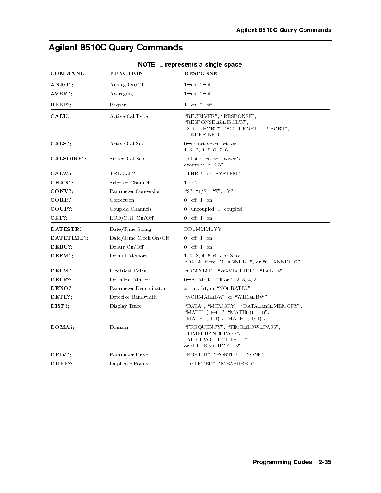
Agilent 8510C Query Commands
NOTE:trepresents a single space
COMMAND FUNCTION RESPONSE
Agilent 8510C Query Commands
ANAO?;
AVER?;
BEEP?;
CALI?;
CALS?;
CALSDIRE?;
CALZ?;
CHAN?;
CONV?;
CORR?;
COUP?;
CRT?;
DATESTR?
DATETIME?;
DEBU?;
DEFM?;
DELM?;
DELR?;
DENO?;
DETE?;
DISP?;
DOMA?;
DRIV?;
DUPP?;
Analog On/O 1=on, 0=o
Averaging 1=on, 0=o
Beeper 1=on, 0=o
Active Cal Type \RECEIVER", \RESPONSE",
\RESPONSEt&tISOL'N",
\S11t1-PORT", \S22t1-PORT", \2-PORT",
\UNDEFINED"
Active Cal Set 0=no active cal set, or
1, 2, 3, 4, 5, 6, 7, 8
Stored Cal Sets \<list of cal sets saved>"
example: \1,2,3"
TRL Cal Z
0
\THRU" or \SYSTEM"
Selected Channel 1or2
Parameter Conversion \S", \1/S", \Z", \Y"
Correction 0=o, 1=on
Coupled Channels 0=uncoupled, 1=coupled
LCD/CRT On/O 0=o, 1=on
Date/Time String DDtMMMtYY
Date/Time Clock On/O 0=o, 1=on
Debug On/O 0=o, 1=on
Default Memory 1, 2, 3, 4, 5, 6, 7 or 8, or
\DATAtfromtCHANNEL 1", or \CHANNELt2"
Electrical Delay \COAXIAL", \WAVEGUIDE", \TABLE"
Delta Ref Marker 0=1tModetO or 1, 2, 3, 4, 5
Parameter Denominator a1, a2, b1, or \NOtRATIO"
Detector Bandwidth \NORMALtBW" or \WIDEtBW"
Display Trace \DATA", \MEMORY", \DATAtandtMEMORY",
\MATHt(t+t)", \MATHt(
t0t
)",
\MATHt(tt)", \MATHt(t/t)",
Domain \FREQUENCY", \TIMEtLOWtPASS",
\TIMEtBANDtPASS",
\AUX.tVOLTtOUTPUT",
or \PULSEtPROFILE"
Parameter Drive \PORTt1", \PORTt2", \NONE"
Duplicate Points \DELETED", \MEASURED"
Programming Codes 2-35

Agilent 8510C Query Commands
NOTE:trepresents a single space (continued)
COMMAND FUNCTION RESPONSE
EXTT?;
FLAT?;
FORM?;
FREA?;
GATE?;
GATS?;
GROU?;
IFGREFA?;
IFGTESA?;
LIMILINE?
LIMIPASSFAIL?
LIMISEGTYPE?
LIMITEST?
LISTAUTF?;
LOAT?;
LOCK?;
LOCKS?;
LOCT?;
LOWP?;
LOWPSET?;
Measurement Trigger mode \INTERNAL" or \EXTERNAL"
Flatness On/O 0=o, 1=on
Format \LOGtMAG", \PHASE", \DELAY",
\SMITHtCHART", \SWR",
\LINEARtMAGNITUDE",
\LINtmkrtontPOLAR",
\LOGtmkrtontPOLAR",
\Re/ImtmkrtontPOLAR",
\INVERTEDtSMITH", \IMAGINARY", \REAL"
Frequency Annotation 0=frequency annotation o,
1=frequency annotation on
Gate On/O 0=Gate O, 1=Gate On
Gate Shap e \MAXIMUM", \WIDE",
\NORMAL", \MINIMUM"
Sweep \CONTINUAL", \HOLD"
Ref IF gain 0, 1, 2, 3, 4, or \AUTO"
Test IF gain 0, 1, 2, 3, 4, or \AUTO"
Limits on/o 0=o, 1=on
Limit test pass/fail status \PASS" \FAIL"
Returns type of active limit \DELETED", \PMIN", \PMAX", \LMIN",
\LMAX"
Limit test on/o 0=o, 1=on
List Autofeed On/O 0=o, 1=on
Load Type \FIXED", \SLIDING", \OFFSET"
Parameter LockTo a1, a2, \NONE"
Lock Sp eed \NORMAL", \FAST"
System Phase Lock \INTERNAL", \EXTERNAL", \NONE"
Time Stimulus \STEP", \IMPULSE"
Set Freq (LowPass) 0=no, 1=yes
MARK?;
MARKMODE?;
MARKSEAR?;
MATH?;
MEDT?;
MENU?;
MKRLIST?;
MKRLISTTYPE?;
MULS?;
NUME?;
NUMS?;
Active Marker 0=All O, 1, 2, 3, 4, 5
Marker Mode \CONTINUOUS", \DISCRETE"
Search Mode \TARGET", \MINIMUM", \MAXIMUM"
Trace Math \PLUS", \MINUS", \MULTIPLY", \DIVIDE"
Cal Std Media Type \COAX" or \WAVEGUIDE"
Menu On/O 0=o, 1=on
Marker List On/O 0=o, 1=on
Marker List Type \FOURtPARAM", \FIVEtMKR"
Multiple Source 0=o,1=on
Parameter Numerator b1, b2, a1, a2, \TESTtCAL",
Freq List Segments
2-36 Programming Codes
\REFtCAL", \DETECTORtGROUND",
\ADCtGROUND", \VCAL", \VREF",
\TEMP.t1", \TEMP.t2"
<
number of segments in frequency list
>
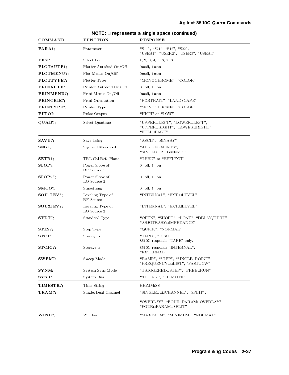
NOTE:trepresents a single space (continued)
COMMAND FUNCTION RESPONSE
Agilent 8510C Query Commands
PARA?;
PEN?;
PLOTAUTF?;
PLOTMENU?;
PLOTTYPE?;
PRINAUTF?;
PRINMENU?;
PRINORIE?;
PRINTYPE?;
PULO?;
QUAD?;
SAVU?;
SEG?;
SETR?;
SLOP?;
SLOP2?;
SMOO?;
SOU1LEV?;
SOU2LEV?;
STDT?;
STES?;
STOI?;
STOIC?;
SWEM?;
SYNM;
SYSB?;
Parameter \S11", \S21", \S12", \S22",
\USER1", \USER2", \USER3", \USER4"
Select Pen 1, 2, 3, 4, 5, 6, 7, 8
Plotter Autofeed On/O 0=o, 1=on
Plot Menus On/O 0=o, 1=on
Plotter Type \MONOCHROME", \COLOR"
Printer Autofeed On/O 0=o, 1=on
Print Menus On/O 0=o, 1=on
Print Orientation \PORTRAIT", \LANDSCAPE"
Printer Type \MONOCHROME", \COLOR"
Pulse Output \HIGH" or \LOW"
Select Quadrant \UPPERtLEFT", \LOWERtLEFT",
\UPPERtRIGHT", \LOWERtRIGHT",
\FULLtPAGE"
Save Using \ASCII", \BINARY"
Segment Measured \ALLtSEGMENTS",
\SINGLEttSEGMENTS"
TRL Cal Ref. Plane \THRU" or \REFLECT"
Power Slop e of
0=o, 1=on
RF Source 1
Power Slop e of
0=o, 1=on
LO Source 2
Smoothing 0=o, 1=on
Leveling Type of
\INTERNAL", \EXT.tLEVEL"
RF Source 1
Leveling Type of
\INTERNAL", \EXT.tLEVEL"
LO Source 2
Standard Type \OPEN", \SHORT", \LOAD", \DELAY/THRU",
\ARBITRARYtIMPEDANCE"
Step Type \QUICK", \NORMAL"
Storage is \TAPE", \DISC"
8510C resp onds \TAPE" only.
Storage is 8510C resp onds \INTERNAL",
\EXTERNAL"
Sweep Mode \RAMP", \STEP", \SINGLEtPOINT",
\FREQUENCYttLIST", \FASTtCW"
System Sync Mo de \TRIGGEREDtSTEP", \FREEtRUN"
System Bus \'LOCAL"', \'REMOTE"'
TIMESTR?;
TRAM?;
WIND?;
Time String HH:MM:SS
Single/Dual Channel \SINGLE
ttt
CHANNEL", \SPLIT",
\OVERLAY", \FOURtPARAMtOVERLAY",
\FOURtPARAMtSPLIT"
Window \MAXIMUM", \MINIMUM", \NORMAL"
Programming Codes 2-37

User Display
(ADDRPASS 31; send data to system bus address)
CS;
DF;
KP;
LB
string CNTL C; Label text. ASCII string terminated with CONTROL C.
PA
x1,y1[,x2,y2 . . . [,xn,yn]]; Plot absolute.
Turn o measurement display.
Set to default state (PU, PA).
Turn o user display.
0x5377,
0y4095.
PD;
PG;
PR
x1,y1[,x2,y2 . . . [,xn,yn]]; Plot relative.
PU;
RP;
RS;
Pen down.
Clear (erase) user display.
Pen up.
Turn on user display.
Turn on measurement display.
Circuit Modeling Program
Statements
nnn
PORT
node (50 ohm termination)
nnnRnode1 node2 resistance
nnnLnode1 node2 inductance
nnnCnode1 node2 capacitance
nnn
TL
node1 node2 Z len Er series corfreq sh
nnn
FREQ
nnn
FREQ LOWPASS
nnn
OUTPUT
nnn
PLOT Snn[,Snn] . . . Plot data on Controller LCD/CRT.
fstart fstop numsteps
fstop numsteps
Snn Send S-parameter data to 8510.
unt
2-38 Programming Codes

GPIB Universal Commands
Note
Commands
CAT
[volume specier]
DEL
GET
lename
HELP
[statement or command]
LIST
RUN
SAVE
nnn represents a line number.
nn
represents S-parameter notation.
OUTPUT and PLOT can also b e used as commands after the program has
been RUN once.
The controller key CLR I/O interupts an executing command and returns the
program to user control.
PURGE
OUTPUT
PLOT
lename
Snn
Snn [, Snn] . . .
END
BYE
EXIT
QUIT
GPIB Universal Commands
DCL
LLO
SPD
SPE
PPU
Device Clear.
Local Lockout, disables 8510 LOCAL key. Must b e cancelled by GTL.
Disable Serial Poll.
Enable Serial Poll.
Not Used.
Programming Codes 2-39

GPIB Addressed Commands
GET
GTL
PPC
REN
SDC
TCT
Group Execute Trigger. (1.) After TRIG, Make next measurement. Bit 2 of
Primary Status Byte set upon completion. (2.) During measurement using
R/T test set with ONE-PATH 2-PORT error model, Continue measurement
after reversing device. Bit 3 of Primary Status Byte set upon completion. (3)
After FASC; data acquisition triggered by external input.
Go to Local. No response to 8510 instructions.
Not Used.
Remote Enable. Enable all GPIB functions.
Selected Device Clear.
Not used
2-40 Programming Codes

States: Preset, Instrument, Hardware
Factory Preset State/Values
The factory preset state consists of the default values selected for various functions. The
following partial list the preset state or value associated with a function. If you have
a question about a specic function, refer to the individual entry in the Alphabetical
Description of Functions section.
Selected Channel = 1, no menu displayed.
NNNNNNNNNNNNNNNNNNNNNNNNNNNNNNNNNNNNNNNNNNNN
4
SAVE
5/4
RECALL
5
instrument states 1 through 8 are not changed bya
FACTORY PRESET
Correction is turned o and the calibration sets are not changed.
NNNNNNNNNNNNNNNNNNNNNNNNNNNNNNNNNNN
SAVE COLORS
selected for the display are the colors returned after
NNNNNNNNNNNNNNNNNNNNNNNNNNNNNNNNNNNNNNNNN
/
RECALL COLORS
are not changed bya
NNNNNNNNNNNNNNNNNNNNNNNNNNNNNNNNNNNNNNNNNNNN
NNNNNNNNNNNNNNNNNNNNNNNNNNNNNNNNNNNNNNNNNNNN
FACTORY PRESET
FACTORY PRESET
. The last colors
is completed.
Stimulus Functions
Maximum sweep range of source and test set.
Number of points = 201.
Source power = depends upon source.
Test set attenuation = 0 dB.
Sweep time = 166 ms.
Ramp sweep.
Continual sweep.
Flatness OFF.
Coupled channels.
3
.
Parameter Functions
Channel 1 = S
Channel 2 = S
11
21
Format Functions
Channel 1 = LOG MAG
Channel 2 = LOG MAG
States: Preset, Instrument, Hardware 3-1

Response Functions
Scale = 10 dB/division.
Reference value = 0 dB.
Reference position = 5.
Coaxial delay.
Electrical delay = 0 seconds.
Averaging OFF.
Smoothing OFF.
Phase oset = 0
Magnitude oset = 0 dB.
Magnitude slopw = 0 dB/GHz.
Measurement Calibration Functions
Correction OFF.
Z0= 50.
Port extensions 1 and 2 are 0 s.
Trim sweep = 0.
Calibration sets 1 through 8 not changed.
Velo city factor = 1.
Domain Functions
Frequency domain.
Gate OFF.
Display Functions
Single channel, single parameter.
Display data.
Trace memories 1 through 8 not changed.
Marker list ON.
Real-time clock ON.
Marker Functions
Markers all OFF.
Delta marker mo de OFF.
System Functions
GPIB addresses not changes.
Display ON.
IF gain = auto.
3-2 States: Preset, Instrument, Hardware
Copy Functions
Plots are full page.
Plot type = color.
Plotter auto-feed ON.
Printer lists all points.
Printer type = mono chrome.
Printer orientation = portrait.
Printer auto-feed ON.
Printer resolution = 96 dpi.
Disc Functions
Storage = internal.
Save, using ASCII (not selectable).
Format = LIF.
Pulse and Waveguide Systems
NNNNNNNNNNNNNNNNNNNNNNNNNNNNNNNNNNNNNNNNNNNN
After a
FACTORY PRESET
to set up one of these systems, you should recall a correct
instrument state, or manually set these following functions:
Sweep Mode = STEP.
Set Z0=1.
Waveguide delay.
Waveguide cuto = depends upon band.
Source number 1 power = depends upon band.
Source number 2 power = depends upon band.
Multiple source ON.
Instrument State
The instrument state consists of those functions that can be sa
ved and recalled. Another way
to dene instrument state:
Those functions that multiple users of a single system are likely to set dierently.
If you have a question about a specic function, refer to the individual entry in the
Alphebetical Description of Functions.
States: Preset, Instrument, Hardware 3-3

Hardware State
In general, the hardware state functions are those that are required for conguration of the
analyzer. These functions are not aected by either
4
USER PRESET
5
, nor by
NNNNNNNNNNNNNNNNNNNNNNNNNNNNNNNNNNNNNNNNNNNN
FACTORY PRESET
Values or text shown in parenthesis are factory default settings.
GPIB Addresses
NNNNNNNNNNNNNNNNNNNNNNNNNNNNNNNNNNNNNNNNNNNNNNN
ADDRESS of 8510
(16)
NNNNNNNNNNNNNNNNNNNNNNNNNNNNNNNNNNNNNNNNNNNNNNNNNNNNNNNNNNNNNNNNN
ADDRESS of SYSTEM BUS
(17)
NNNNNNNNNNNNNNNNNNNNNNNNNNNNNNNNNNNNNNNNNNNNNNNNNNNNNNNNNNNNNN
ADDRESS of SOURCE #1
(19)
NNNNNNNNNNNNNNNNNNNNNNNNNNNNNNNNNNNNNNNNNNNNNNNNNNNNNNNNNNN
ADDRESS of TEST SET
(20)
NNNNNNNNNNNNNNNNNNNNNNNNNNNNNNNNNNNNNNNNNNNNNNNNNNNNNNNN
ADDRESS of PLOTTER
(GPIB, 5)
NNNNNNNNNNNNNNNNNNNNNNNNNNNNNNNNNNNNNNNNNNNNNNNNNNNNNNNN
ADDRESS of PRINTER
(GPIB, 1)
NNNNNNNNNNNNNNNNNNNNNNNNNNNNNNNNNNNNNNNNNNNNNNN
ADDRESS of DISC
(0)
NNNNNNNNNNNNNNNNNNNNNNNNNNNNNNNNNNNNNNNNNNNNNNNNNNNNNNNNNNNNNN
ADDRESS of SOURCE #2
(31)
NNNNNNNNNNNNNNNNNNNNNNNNNNNNNNNNNNNNNNNNNNNNNNNNNNNNNNNNNNNNNN
ADDRESS of PASS-THRU
(31)
NNNNNNNNNNNNNNNNNNNNNNNNNNNNNNNNNNNNNNNNNNNNNNNNNNNNNNNNNNNNNN
ADDRESS of RF SWITCH
(31)
NNNNNNNNNNNNNNNNNNNNNNNNNNNNNNNNNNNNNNNNNNNNNNNNNNNNNNNNNNNNNNNNN
ADDRESS of POWERMETER
(13)
System phaselocktyp e = internal.
System phaselock speed = normal.
.
System phaselock step type = reads source in system to determine.
Multiple source values:
RF Source #1
Numerator = 0
Denominator = 1
Oset = 0
LO Source #2
Numerator = 0
Denominator = 1
Oset = 0
Receiver
Numerator = 1
Denominator = 1
Oset = 0
GPIB Response to
PRES;
command (user preset).
Warning beep er ON.
Power level RF source #1 = 0 dBm.
Power level RF source #2 = 0 dBm.
3-4 States: Preset, Instrument, Hardware
 Loading...