

Page 1
Agilent Technologies
11716A/C
Interconnection Kit
Operating Note
Agilent Part Number: 11716-90004
Printed in USA
June 2002
Supersedes: April 2002
Page 2

Notice
The information contained in this document is subject to change without
notice.
Agilent Technologies makes no warranty of any kind with regard to this
material, including, but not limited to, the implied warranties of
merchantability and fitness for a particular purpose. Agilent Technologies
shall not be liable for errors contained herein or for incidental or
consequential damages in connection with the furnishing, performance, or
use of this material.
Agilent Technologies assumes no responsibility for the use or reliability of
its software on equipment that is not furnished by Agilent Technologies.
This document contains proprietary information which is protected by
copyright. All rights are reserved. No part of this document may be
photocopied, reproduced, or translated to another language without prior
written consent of Agilent Technologies.
Restricted Rights Legend
Use, duplication, or disclosure by the U.S. Government is subject to
restrictions as set forth in subparagraph (c)(1)(ii) of the Rights in Technical
Data and Computer Software clause at DFARS 252.227-7013 for DOD
agencies, and subparagraphs (c)(1) and (c)(2) of the Commercial Computer
Software Restricted Rights clause at FAR 52.227-19 for other agencies.
© Copyright 1994, 1996, 1997, 2001, 2002 Agilent Technologies, Inc
ii 11716A/C Operating Note
Page 3

Warranty
Certification Agilent Technologies certifies that this product met its published
specifications at the time of shipment from the factory.
Documentation Warranty
THE MATERIAL CONTAINED IN THIS DOCUMENT IS
PROVIDED "AS IS," AND IS SUBJECT TO BEING CHANGED,
WITHOUT NOTICE, IN FUTURE EDITIONS. FURTHER, TO
THE MAXIMUM EXTENT PERMITTED BY APPLICABLE LAW,
AGILENT DISCLAIMS ALL WARRANTIES, EITHER EXPRESS
OR IMPLIED WITH REGARD TO THIS MANUAL AND ANY
INFORMATIONCONTAINEDHEREIN,INCLUDING BUTNOT
LIMITED TO THE IMPLIED WARRANTIES OF
MERCHANTABILITY AND FITNESS FOR A PARTICULAR
PURPOSE. AGILENT SHALL NOT BE LIABLE FOR ERRORS
OR FOR INCIDENTAL OR CONSEQUENTIAL DAMAGES IN
CONNECTION WITH THE FURNISHING, USE, OR
PERFORMANCE OF THIS DOCUMENT OR ANY
INFORMATION CONTAINED HEREIN. SHOULD AGILENT
AND THE USER HAVE A SEPARATE WRITTEN AGREEMENT
WITH WARRANTY TERMS COVERING THE MATERIAL IN
THIS DOCUMENT THAT CONFLICT WITH THESE TERMS,
THE WARRANTY TERMS IN THE SEPARATE AGREEMENT
WILL CONTROL.
Assistance Product maintenance agreements and other customer assistance agreements
are available for Agilent Technologies products.
For assistance, call your local Agilent Technologies Sales and Service Office
(refer to “Support and Service”).
11716A/C Operating Note iii
Page 4

Support and Service
You can find a list of local service representatives on the Web at:
http://www.agilent.com/find/assist
Click on “Contact Us” and select your country.
If you do not have access to the Internet, one of these centers can direct you
to your nearest Agilent Technologies representative:
United States (800) 403-0801
Canada (877) 429-9969
Europe (41 22) 780.6111 (Switzerland)
(33 1) 69 82 66 66 (France)
(49 7031) 464-6222 (Germany)
(44 188) 9696622 (Great Britain)
Japan 0120-32-0119
Latin America (11) 7297-3700 (Brazil)
Australia/New
Zealand
Asia-Pacific 080-047-669
1-800-802-540 (Australia)
0800-738-378 (New Zealand)
iv 11716A/C Operating Note
Page 5

General Information
General Information
This operating note contains information for the 11716A and 11716C
Interconnection Kits. Included in the note is a list of parts with part numbers
and instructions for using the kit.
Description The 11716A and 11716C Interconnection Kit provides the necessary parts to
connect various attenuators in series. See Table 1 for possible combinations.
The 11716A interconnection ridged cable has type-N connectors, and the
11716C has SMA connectors.
• Overall height with attenuators is 3.235 inches.
• Typical return loss of the cable is ≤20 dB.
Interconnection Kit Matrix
Items Supplied
Table 1 Interconnection Kit Parts
8494 8495 8496
8494 Yes Yes Yes
8495 Yes No Yes
8496 Yes Yes Yes
Parts included in the interconnection kits are listed in Table 2.
Table 2 Interconnection Kit Parts
Description Qty Part Number
Combining bracket 1 11716-00001
Base 1 11716-00002
Interconnect rigid cable
Type-N male connectors 11716A
SMA connectors 11716C
1
1
11716-20001
11716-20003
Felt feet 4 0403-0309
Screw 4-40 x 7.9 mm (0.312 inch) 4 2200-0105
Screw 4-40 x 9.5 mm (0.375 inch) 2 2220-0769
11716A/C Operating Note 1
Page 6

Installation
Installation
Initial Inspection Inspect the shipping container for damage. Inspect the kit for any
mechanical damage incurred in transit. If the shipping container or
cushioning material is damaged, it should be kept until the contents of the
shipment have been checked for completeness and the kit has been checked
mechanically and electrically.
If the contents of this shipment are incomplete, or if there is mechanical
damage or defect, notify the nearest Agilent Technologies Office. If the
shipping container is damaged, or the cushioning material shows signs of
stress, notify the carrier as well as the Agilent Technologies office. At
Agilent’s option, the office will arrange for repair or replacement without
waiting for claim settlement.
Installing Interconnection Kit
CAUTION Do not allow connectors on the Interconnection Kit to bear torque or support
weight.
To connect two attenuators using the kit:
1. Remove the pedestal bases of both attenuators.
2. Select the attenuator to be located on top and connect it to the outer
bracket surface that has the three small holes. Use two of the
4-40 x 7.9 mm (0.312 inch) screws supplied.
NOTE If one of the two attenuators is an 8495 70 dB attenuator, this physically
shorter unit should be selected for the top location.
3. Fasten the remaining attenuator to the inside of the bracket, with or
without the sheet metal base. The screws should pass through the two
elongated holes. Do not tighten these screws at this time.
NOTE The 4-40 x 9.5 mm (0.375 inch) screws are for fastening to a plastic
attenuator pedestal base. The 4-40 x 7.9 mm (0.312 inch) are for fastening to
the bracket.
2 11716A/C Operating Note
Page 7
Installation
4. Connect the rigid cable between the two attenuators. The lower
attenuator should be adjusted laterally so that the rigid cable connects
easily without strain.
5. Firmly tighten the two screws holding the lower attenuator to the
bracket.
6. If no sheet metal base is being used, the adhesive-backed felt feet that
are supplied may be attached to the underside of the bracket to prevent
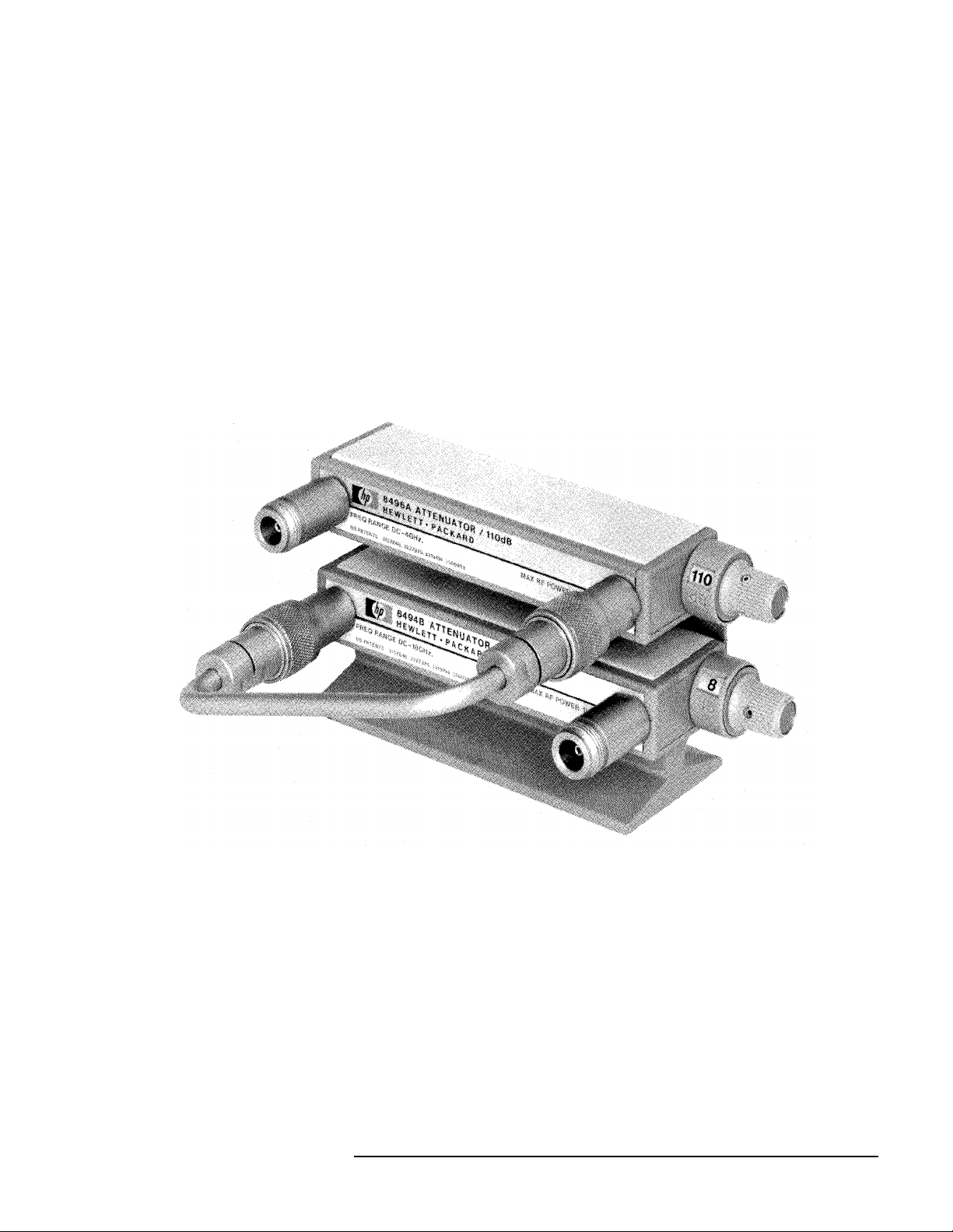
marring the surface on which the combined attenuators are set. Figure 1
shows how the interconnection kit is typically used.
7. When using the sheet metal base, use the .375 long screws to connect the
attenuator bracket to the sheet metal base.
Figure 1 Typical Installation
11716A/C Operating Note 3
 Loading...