

Page 1

Agilent 54006A
High Frequency Probe
User’s Guide
Agilent Technologies
Page 2

Notices
© Agilent Technologies, Inc. 1988 - 2007
No part of this manual may be reproduced in any
form or by any means (including electronic storage and retrieval or translation into a foreign language) without prior agreement and written
consent from Agilent Technologies, Inc. as governed by United States and international copyright lays.
Manual Part Number
54006-90002
Edition
June 2007
Printed in USA
Agilent Technologies, Inc.
Digital Signal Analysis Division
1400 Fountaingrove Parkway
Santa Rosa, CA 95403, USA
Warranty
The material contained in this document is provided “as is,” and is subject to being changed,
without notice, in future editions. Further, to the
maximum extent permitted by applicable law,
Agilent disclaims all warranties, either express or
implied, with regard to this manual and any information contained herein, including but not limited
to the implied warranties of merchantability and
fitness for a particular purpose. Agilent shall not
be liable for errors or for incidental or consequential damages in connection with the furnishing,
use, or performance of this document or of any
information contained herein. Should Agilent and
the user have a separate written agreement with
warranty terms covering the material in this document that conflict with these terms, the warranty
terms in the separate agreement shall control.
Safety Notices
CAUTION
Caution denotes a hazard. It calls attention to a
procedure which, if not correctly performed or
adhered to, could result in damage to or destruction of the product. Do not proceed beyond a caution sign until the indicated conditions are fully
understood and met.
WARNING
Warning denotes a hazard. It calls attention to
a procedure which, if not correctly performed or
adhered to, could result in injury or loss of life. Do
not proceed beyond a warning sign until the indicated conditions are fully understood and met.
2
Page 3
54006A User’s Guide
The Agilent 54006A—at a glance
The Agilent 54006A—at a glance
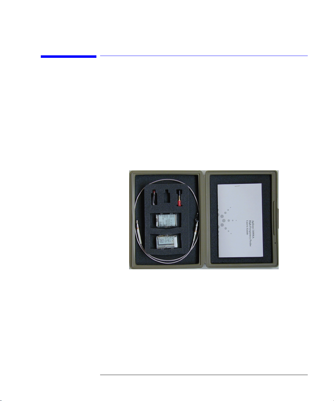
The Agilent 54006A high frequency probe provides passive probing of high
speed logic circuits and low impedance circuits. The major advantage of this
probe is the small amount of capacitive probe tip loading (approximately
250 fF). This makes it possible to probe high frequency circuits without disturbing the circuit with a large capacitive load. Two probe body assemblies are
provided with the 54006A giving you the choice of 10:1 and 20:1 probe tip division ratios that may be used with any 50 ohm input instrument. The 20:1
probe assembly is 5 mm (0.2 in.) longer than the 10:1 probe assembly.
Contents Unpacking the Probe 4
Using the Probe 5
To replace the probe resistor 6
To protect against electrostatic damage 7
Specifications and Characteristics 9
Replaceable Parts 12
Contacting Agilent 13
Preparing the probe for shipping 13
3
Page 4

54006A User’s Guide
Unpacking the Probe
Unpacking the Probe
1 Inspect the shipment including the shipping container and probe for damage.
CAUTION Do not bend the coaxial cable to a radius of less than 1 in (2.54 cm) or internal
damage to the cable may occur.
2 Locate the shipping list. Verify that you received all the accessories on this list,
and all the options that you ordered. The following list shows some of the items
that may be on the shipping list. The information on your actual shipping list is
more accurate and should supersede the information in this list.
❒ 10:1 probe body assembly
❒ 20:1 probe body assembly
❒ Packag of five 450Ω resistor replacements and one sleeve
❒ Packag of five 950Ω resistor replacements and one sleeve
❒ Coaxial cable, 91 cm (36 in.) long, SMA male connectors
❒ DC blocking capacitor
❒ SMA (f) to BNC (m) adapter
Notice that the 20:1 probe assembly is 5 mm (0.2 in.) longer than the 10:1
probe assembly.
If anything is missing or defective, contact your nearest Agilent Technologies
Service Office. Refer to “Contacting Agilent” on page 13. If the shipment was
damaged, contact the carrier, then contact the nearest Agilent Sales Office.
Keep the shipping materials for the carrier’s inspection. The Agilent Sales
Office will arrange for repair or replacement at Agilent’s option without waiting for claim settlement.
3 Select one of the probe body assemblies and attach it to either end of the
coaxial cable supplied with the probe. The SMA connector can either be finger
tight or torqued to 5 in. lbs.
4
Page 5
54006A User’s Guide
Using the Probe
Using the Probe
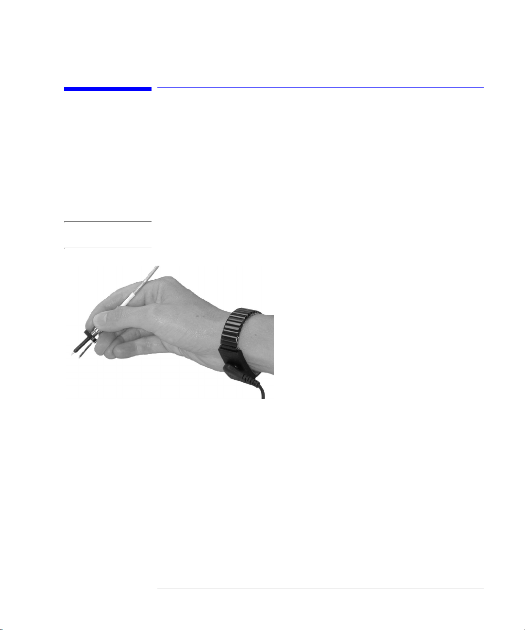
The 54006A high frequency probe may be used with any 50-ohm input instrument. Figure 1 shows the correct technique for holding the probe while making measurements. Hold the probe by its SMA connector. Placing your hand
closer to the probe tip adds capacitance to the probe and degrades the probe
response.
CAUTION Do not bend the coaxial cable to a radius of less than 1 in (2.54 cm) or internal
damage to the cable may occur.
Figure 1. Correct method of holding the probe
Electrostatic Buildup Before connecting the probe to the digitizing oscilloscope or digital communi-
cations analyzer, eliminate electrostatic buildup from the probe cable. Electrostatic discharge can damage the instrument’s inputs. To discharge the probe
cable, connect a female short to either end of the cable. Also, briefly touch a
short to the instrument’s input connector. Always wear a wrist strap connected to an antistatic mat. Refer to “To protect against electrostatic damage”
on page 7 for information on setting up a static safe workstation.
5
Page 6
54006A User’s Guide
Using the Probe
Connector Savers The supplied probe cable has a male connector on each end. If your instru-
ment has a connector saver (female-to-female adapter) use it to connect the
probe to the instrument’s input connector. Using a connector saver prevents
damage to the precision male input connectors on the instrument. The connector saver's part number is 5061-5311.
Oscilloscope’s Probe
Attenuation Setting
Probe Resistor Tips The resistor probe tips are susceptible to wear depending on the amount of
On the oscilloscope, change the probe attenuation setting to 10:1 or 20:1
depending on which divider you are using with the probe. The oscilloscope
will now display the correct volts-per-div ranges and display the correct voltage levels when voltage measurements are made with the probe.
The resistor probe tips are precut at the factory to a recommended maximum
length. This recommended length allows for a probe tip input capacitance of
approximately 250 fF. Longer resistor leads add input capacitance and
shorter resistor leads decrease the input capacitance. If the resistor lead is
completely cut off, the probe's input capacitance will approach 100 fF.
usage. Because the resistor probe tips a consumable part that may require
periodic replacement, a package of five resistor replacements are supplied for
each of the probe tips. For instructions on ordering additional resistor
replacement packages, referred to replaceable parts section. To replace a
resistor probe tip, refer to “To replace the probe resistor” on page 6.
To replace the probe resistor
To replace the resistor inside the probe assembly, perform the following steps.
1 If the probe is connected to an instrument, use a wrist strap which is attached
to an antistatic mat. Detach the probe from the instrument.
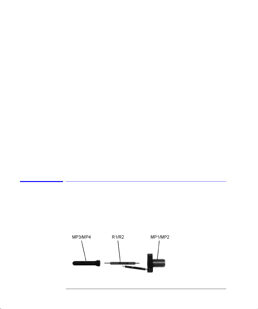
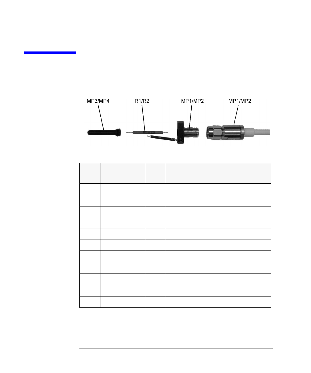
2 Unscrew the probe sleeve (MP3/MP4) from the probe assembly.
Figure 2. Probe Sleeve and Resistor
6
Page 7

54006A User’s Guide
Using the Probe
3 Pull the resistor (R1/R2) out of the probe assembly.
4 Obtain a new resistor from the bag of five resistor replacements.
5 Insert the resistor lead into the center hole located on the probe assembly
socket.
6 Screw the probe sleeve into the probe assembly.
7 Attach a female short to the cable’s SMA connector and touch the short to any
test set’s connector hex nuts. Reattach the probe to the instrument.
To protect against electrostatic damage
Electrostatic discharge (ESD) can damage or destroy the input circuits of an
instrument that the probe is connected to. ESD can also damage or destroy
electronic components that you are measuring. All work should be performed
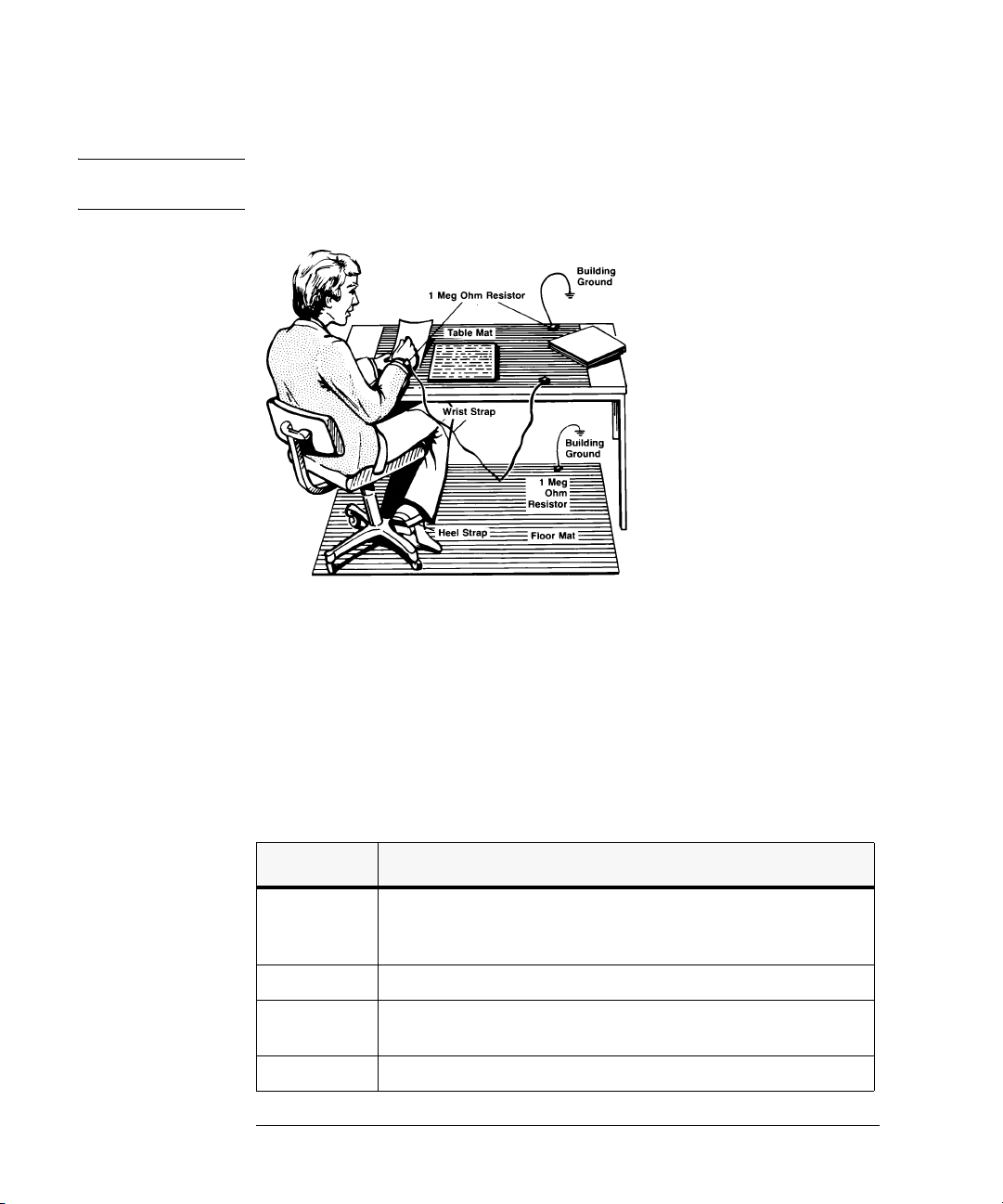
at a static-safe work station. Figure 3 on page 8 shows an example of a staticsafe work station (without the instrument) using two types of ESD protection:
• Conductive table-mat and wrist-strap combination.
• Conductive floor-mat and heel-strap combination.
Both
types, when used together, provide a significant level of ESD protection.
Of the two, only the table-mat and wrist-strap combination provides adequate
ESD protection when used alone. To ensure user safety, the static-safe accessories must provide at least 1 MΩ of isolation from ground. Refer to Table 1 for
information on ordering static-safe accessories.
7
Page 8
54006A User’s Guide
Using the Probe
W A R N I NG These techniques for a static-safe work station should not be used when working
on circuitry with a voltage potential greater than 500 volts.
Figure 3. Static-Safe Accessories
Reducing ESD
Damage
The following suggestions may help reduce ESD damage that occurs during
testing and servicing operations.
• Personnel should be grounded with a resistor-isolated wrist strap before
removing any assembly from the unit.
• Be sure all instruments are properly earth-grounded to prevent a buildup of
static charge.
Table 1. Static-Safe Accessories
Part Number Description
9300-0797
9300-0980 Wrist-strap cord 1.5 m (5 ft)
9300-1383 Wrist-strap, color black, stainless steel, without cord, has four adjustable links
9300-1169 ESD heel-strap (reusable 6 to 12 months).
8
3M static control mat 0.6 m
(The wrist-strap and wrist-strap cord are not included. They must be ordered
separately.)
and a 7 mm post-type connection.
× 1.2 m (2 ft× 4 ft) and 4.6 cm (15 ft) ground wire.
Page 9
54006A User’s Guide
Specifications and Characteristics
Specifications and Characteristics
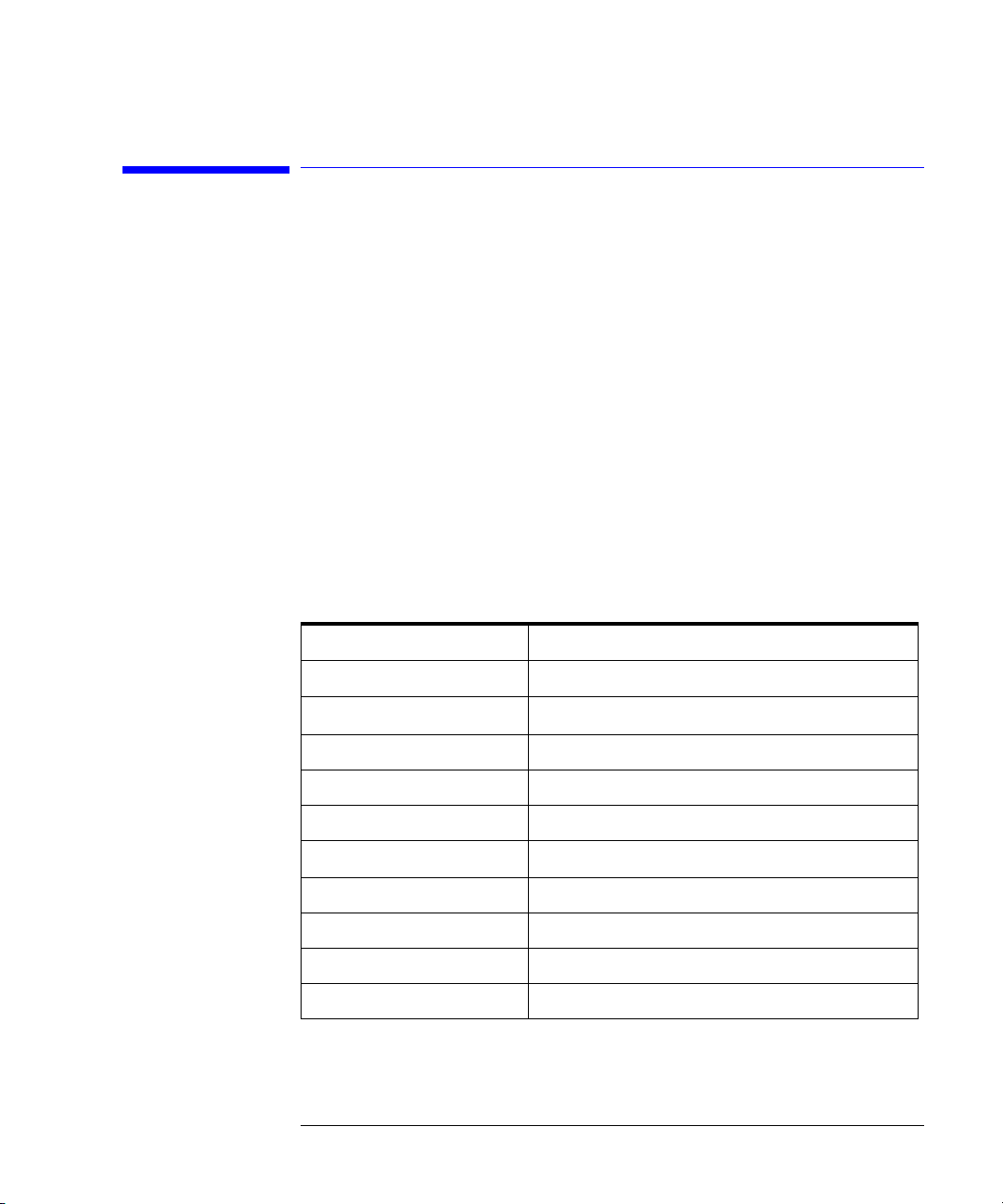
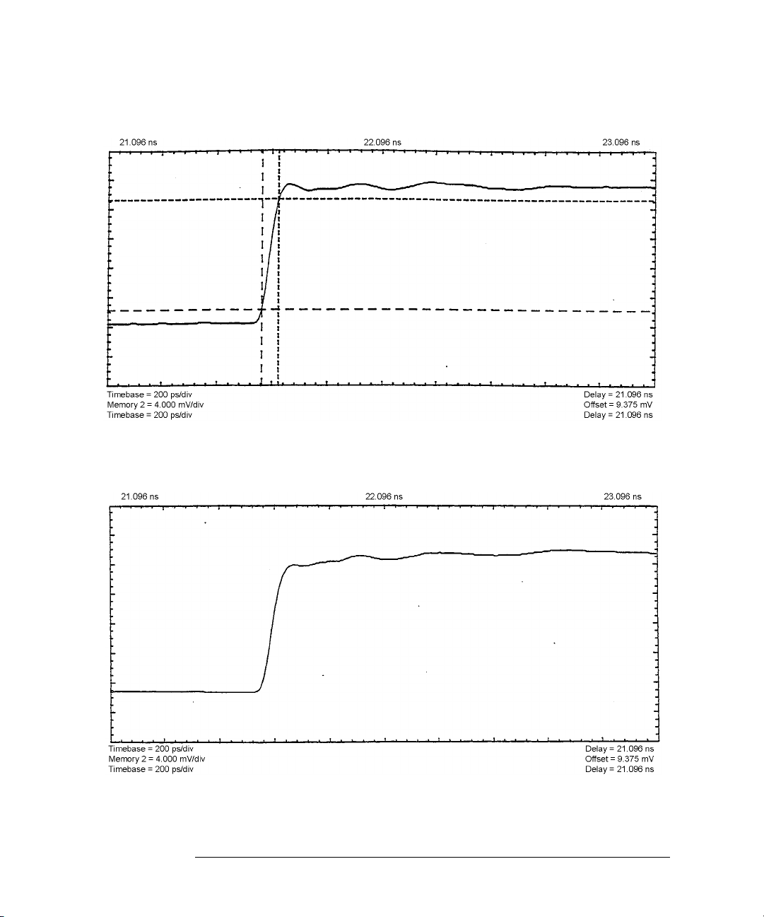
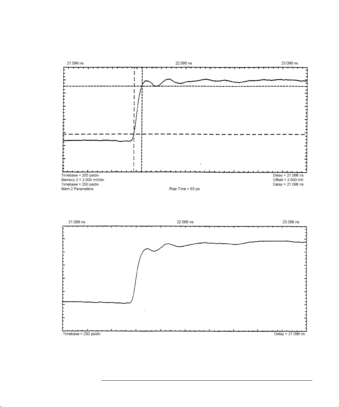
This chapter lists specification and characteristics of the Agilent 54006A. Figures in this section show the characteristic step response of the probe.
Notice that cable length affects the probe's response. Using longer or higher
loss cables degrades the probe's response even more.
• Specifications describe warranted performance over the temperature range
listed in the table (unless otherwise noted). All specifications apply after the
probe’s temperature has been stabilized after 15 minutes of continuous operation.
• Characteristics provide useful information by giving functional, but nonwarranted, performance parameters. Characteristics are printed in italics.
Table 2. Specifications and Characteristics
Bandwidth
Input Resistence 10:1 probe
Input Resistence 20:1 probe
Maximum input voltage 20 Vpeak
Use indoor
Input capacitance 250 fF (characteristic)
Temperature
Humidity Operating - up to 95% (characteristic)
Altitude 4,600 meters (15,000 feet) (characteristic)
Length 91 cm (36 in.) (characteristic)
Connectors SMA male
a. Driven by a 25 ohm source.
b. 1% probe resistor terminated into nominal 50 ohm oscilloscope input.
a
b
b
dc to 6 GHz
500Ω
1 kΩ
–25
° C (–13° F ) to +65° C (149° F) (characteristic)
9
Page 10
54006A User’s Guide
Specifications and Characteristics
Figure 4. Characteristic step response of 500Ω probe to 50 ps step without 36” cable
Figure 5. Characteristic step response of 500Ω probe to 50 ps step with 36” cable
10
Page 11
54006A User’s Guide
Specifications and Characteristics
Figure 6. Characteristic step response of 1 kΩ probe to 50 ps step without 36” cable
Figure 7. Characteristic step response of 1 kΩ probe to 50 ps step with 36” cable
11
Page 12
54006A User’s Guide
Replaceable Parts
Replaceable Parts
Agilent Part
Part
C1 11742A 1 DC blocking capacitor
Number
Qty Description
MP1 54006-67601 1
MP2 54006-67602 1
MP3 54006-21701 1 Sleeve for MP1
MP4 54006-21702 1 Sleeve for MP2
MP5 1250-2015 1 Adapter, SMA (f) to BNC (m)
MP6 54006-68701 1
MP7 54006-68702 1
R1 0699-2370 1
R2 0699-2371 1
W1 8210-4977 1 Coaxial cable, SMA (m-m), 36 inches
Probe body assembly for 450Ω resistor
Probe body assembly for 950
Pack of five 450
Pack of five 950Ω resistors for R1 and 1 extra MP4
Thick film resistor, 950
Thick film resistor, 450
Ω resistors for R2 and 1 extra MP3
Ω resistor
Ω resistor, 1W
Ω resistor, 0.8W
Figure 8. Agilent 54006A Replaceable Parts
12
Page 13

54006A User’s Guide
Contacting Agilent
Contacting Agilent
For technical assistance, you can contact your local Agilent call center. In the
Americas, call 1 (800) 452-4844. In other regions, visit http://www.agilent.com
and click Contact Us. Before returning an probe for service, you must first call
the Instrument Support Center, in all regions, at (800) 403-0801. Any special
arrangements for the probe can be discussed at this time. This will help the
service office repair and return your probe as quickly as possible.
If the probe is under warranty or is covered by an Agilent maintenance contract, it will be repaired under the terms of the warranty or contract. If the
probe is no longer under warranty or is not covered by an Agilent maintenance plan, Agilent will notify you of the cost of the repair after examining
the unit. When an probe is returned to a Agilent service office for servicing, it
must be adequately packaged and have a complete description of the failure
symptoms attached. When describing the failure, please be as specific as possible about the nature of the problem.
Preparing the probe for shipping
1 Write a complete description of the failure and attach it to the probe. Include
any specific performance details related to the problem. The following
information should be returned with the probe.
• Type of service required.
• Date probe was returned for repair.
• Description of the problem:
• Whether problem is constant or intermittent.
• Whether probe is temperature-sensitive.
• Whether probe is vibration-sensitive.
• Performance data.
• Company name and return address.
• Name and phone number of technical contact person.
• Model number of returned probe.
• Full serial number of returned probe.
• List of any accessories returned with probe.
13
Page 14

54006A User’s Guide
Contacting Agilent
CAUTION Cover electrical connectors to protect sensitive components from electrostatic
damage. Cover optical connectors to protect them from damage due to physical
contact or dust.
CAUTION Probe damage can result from using packaging materials other than the original
materials. Never use styrene pellets as packaging material. They do not
adequately cushion the probe or prevent it from shifting in the carton. They
may also cause probe damage by generating static electricity.
2 Pack the probe in the original shipping containers. Original materials are
available through any Agilent office. Or, use the following guidelines:
• Wrap the probe in antistatic plastic to reduce the possibility of damage
caused by electrostatic discharge.
• For probes weighing less than 54 kg (120 lb), use a double-walled, corrugated cardboard carton of 159 kg (350 lb) test strength.
• The carton must be large enough to allow approximately 7 cm (3 inches) on
all sides of the probe for packing material, and strong enough to accommodate the weight of the probe.
• Surround the equipment with approximately 7 cm (3 inches) of packing material, to protect the probe and prevent it from moving in the carton. If packing foam is not available, the best alternative is S.D-240 Air Cap™ from
Sealed Air Corporation (Commerce, California 90001). Air Cap looks like a
plastic sheet filled with air bubbles. Use the pink (antistatic) Air Cap™ to
reduce static electricity. Wrapping the probe several times in this material
will protect the probe and prevent it from moving in the carton.
3 Seal the carton with strong nylon adhesive tape.
4 Mark the carton “FRAGILE, HANDLE WITH CARE”.
Retain copies of all shipping papers.
14
 Loading...