

Page 1

HP 53131A/132A 225 MHz
Universal Counter
Operating
Guide
Page 2

Page 3

Operating Guide
This guide describes how to use the HP 53131A/132A 225 MHz Universal
Counter. The information in this guide applies to instruments having the
number prefix listed below, unless accompanied by a “Manual Updating
Changes” package indicating otherwise.
SERIAL PREFIX NUMBER: 3313A to 3736A (HP 53131A)
3352A to 3736A (HP 53132A)
HP 53131A/132A 225 MHz
Universal Counter
Page 4

Copyright Hewlett- P ac ka rd
Company 1999
All Rights Reserved.
Reproduction, adaptation, or
translations without prior
written permission is
prohibited, except as allowed
under the copyright laws.
Printed: May 1999
Printed in USA
Manual part number
53131-90055
Certification
and Warranty
Certification
Hewlett-Packard Company
certifies that this product met
its published specification at the
time of shipment from the
factory. Hewlett-Packard
further certifies that its
calibration measurements are
traceable to the United States
National Institute of Standards
and Technol ogy (formerly
National Bureau of Standards),
to the extent allowed by the
Institute’s calibration facility,
and to the calibration facilities
of other International
Standards Organization
members.
Warranty
HP warrants HP hardware,
accessories and supplies against
defects in materials and
workmanship for a period of
three years from date of
shipment. If HP receives notice
of such defects during the
warranty period, HP will, at its
option, either repair or replace
products which prove to be
defective. Replacement products
may be either new or like-new.
HP warrants that HP software
will not fail to execute its
programming instructions, for
the period specified above, due
to defects in material and
workmanship when properly
installed and used. If HP
receives notice of such defects
during the warranty period, HP
will replace software media
which does not execute its
programming instructions due
to such defects.
For detailed warra nty
information, see back matter.
Safety Considerations
General
This product and related
documentation must be
reviewed for familiarizat ion
with this safety marki ngs and
instructions before operation.
Before Cleaning
Disconnect the product from
operating power before
cleaning.
Warning Symbols That May
Be Used In This Book
Instruction manual symbol; the
product will be marked with
this symbol when it is necessary
for the user to refer to the
instruction manual.
Indicates hazardous voltages.
Indicates earth (ground)
terminal.
or
Indicates terminal is con n ected
to chassis when such connection
is not apparent.
Indicates Alternating current.
Indicates Direct current.
Safety Considerations
(contd)
WARNING
BODILY INJUR Y OR DEATH
MAY RESULT FROM
FAILURE TO HEED A
WARNING. DO NOT
PROCEED BEYOND A
WARNING UNTIL THE
INDICATED CONDITIONS
ARE FULLY UNDERSTOOD
AND MET .
CAUTION
Damage to equipment, or
incorrect measurement data,
may result from failure to
heed a caution. Do not
proceed beyond a CAUTION
until the indicated conditions
are fully understood and met.
Safety Earth Ground
An uninterruptible safety earth
ground must be maintained
from the mains power source to
the product’s ground circuitry.
WARNING
WHEN MEASURING POWER
LINE SIGNALS, BE
EXTREMELY CAREFUL AND
ALWAYS USE A
STEP-DOWN ISOLATION
TRANSFORMER WHICH
OUTPUT IS COMPATIBLE
WITH THE INPUT
MEASUREMENT
CAPABILITIES OF THIS
PRODUCT. THIS PRODUCT’S
FRONT AND REAR PANELS
ARE TYPCIALLY AT EARTH
GROUND.
TO MEASURE AC POWER
LINE SIGNALS WITHOUT AN
ISOLATION TRANSFORMER.
For additional safety and
acoustic noise information, see
back matter.
THUS, NEVER TRY
Hewlett-Packard Company 7.NC.NL.A.11.03.97.R1.P.CW6FC
Santa Clara Division
5301 Stevens Creek Boulevard
Santa Clara, California 95052-8059
Page 5

Contents
In This Guide
Contents and Organization xii
Related Documents xiii
Types of Service Available if Your Instrument Fails xiv
Standard Repair Services (Worldwide) xiv
Express Repair/Performance Calibration Service
(USA Only) xiv
Assembly-Level Service Guide xiv
Repackaging for Shipment xv
Description of the 225 MHz Universal Counter xvi
Options xviii
Hardware xviii
Support xviii
Accessories Supplied and Available xix
Accessories Supplied xix
Accessories Available xix
Supplied Manuals xix
Differences Between Prior and Current Revisions of the
HP 53131A/132A xx
HP 53131A Containing Firmware Revisions (3317, 3335, or
3402) xx
Calibrations xxi
Measurements xxi
Statistics xxii
HP-IB Commands xxii
HP 53132A Time Interval Delay Arming xxii
Operating Guide iii
Page 6

Contents
HP 53131A/132A Quick Reference Guide xxiii
1 Getting Started
The Front Panel at a Glance 1-2
The Front Panel Indicators at a Glance 1-3
The Front Panel Indicators at a Glance (Cont.) 1-4
The Front Panel Menus at a Glance 1-5
The Front Panel Menus at a Glance (Cont.) 1-6
The Front Panel Menus at a Glance (Cont.) 1-7
The Front Panel Menus at a Glance (Cont.) 1-8
The Display Annunciators at a Glance 1-9
The Display Special Character at a Glance 1-10
The Limit Test Graph Characters at a Glance 1-10
The Rear Panel at a Glance 1-11
Making Measurements 1-12
To Measure Frequency 1-13
To Select Input Coupling and Impedance 1-15
Selecting Input Coupling 1-15
Selecting Input Impedance 1-16
To Set Input Channel Trigger Level/Sensitivity 1-17
Changing Trigger Mode 1-17
Modifying Input Trigger Level 1-17
Selecting Input Trigger Slope 1-18
Selecting Input Sensitivity 1-19
Starting the Measurement 1-19
To Select Scale and Offset 1-19
Entering the Scale Value 1-20
Entering the Offset Value 1-21
Displaying the Math Results 1-22
Disabling Math 1-22
To Set Limits of Measurements 1-23
Setting the Upper Limit 1-24
Setting the Lower Limit 1-26
iv Operating Guide
Page 7

Contents
Setting the Counter to Flag and Stop Measuring On
Out-of-Limit Measurements 1-28
Setting the Counter to Flag On Limits But Continue
Measuring 1-29
Disabling Limit Testing 1-30
Disabling Math 1-30
To Perform Statistics on Measurements 1-31
Selecting the Type of Statistic s (Stats) 1-31
Computing Stats on Filtered Data Only 1-32
Displaying Stats After Filtering Data of Input
Signal 1-34
Disabling Stats and Math 1-35
To Control Measurement 1-36
2 Operating Your Universal Counter
Introduction 2-2
Chapter Summary 2-2
Where to Find Some Key Working Examples 2-3
How this Counter Wor k s for You 2-4
Using the Measurement Control Keys (Run and Stop/
Single) 2-5
Overview of the Measurement Control Keys 2-5
To Use the Measurement Control Keys 2-6
Using Entry/Select (Arrow) Keys 2-8
To Use During Numeric Entry 2-8
To Use When Sequencing Through the Measurement
Function Menus (Freq & Ratio, Time & Period, Other Meas)
and the Recall Menu 2-8
To Use During State Changing (ON/OFF, LO/MED/HI,
etc.) 2-9
To Use on Prompted Event Messages (SET OFFSET ?, CAL:
OFFS n ?, TEST: ALL?, etc.) 2-9
To Use on Prompted Help Messages (MATH HELP ?,
PRINT HELP ?) 2-9
Operating Guide v
Page 8

Contents
Using the MEASURE Menu Keys 2-10
Overview of the MEASURE Menus 2-10
To Measure Frequency 2-11
To Measure Frequency Ratio 2-12
To Measure Time Interval 2-13
To Measure Period 2-13
To Measure Rise/Fall Times 2-13
To Measure Positive/Negative Pulse Widths 2-14
To Measure Duty Cycle 2-14
To Make Totalize Measurements 2-14
To Make Phase Measurements 2-15
To Measure Positive/Negative Voltage Peaks 2-15
Using the Gate & External Arm Menu Key 2-16
Overview of Gate/External Arming Functions 2-16
Gate/External Arming Capabilities 2-16
AUTO Arming 2-16
EXTERNAL Arming 2-17
TIME Arming 2-17
DIGITS Arming 2-17
HP 53131A (and HP 53132A With S/N Prefix Below
3646) Time Interval DELAY Arming 2-17
HP 53132A (With S/N Prefix 3646 and Above) Time
Interval DELAY Arming 2-20
To Use the Gate and External Arm 2-24
Example Procedure for Gate and External Arm 2-24
Example Procedure for Changing the Number of
Digits of Resolution Displayed for More
Precise Measurements 2-25
Using the MATH Menu Keys 2-27
Overview of Scale/Offset Math Menu 2-27
To Use the Scale/Offset Math Menu 2-28
Example Procedure for Scale Function 2-28
Example Procedure for Offset Function 2-29
vi Operating Guide
Page 9

Contents
Example Procedure for Turning Off Math Mode 2-30
Example Procedure for Setting the Offset From
the Last Measurement Value 2-31
Overview of Statistics (Stats) Menu 2-32
To Use the Stats Menu for Automatic and Continuous
Statistical Analysis 2-33
Example Procedure for Computing Stats 2-33
Example Procedure for Easy Viewing of Stats 2-34
Example Procedure for Filtering Data (Using Limits)
During Stats 2-35
Example Procedure for Configuring SINGLE to Initiate
N Measurements 2-36
Example Procedure for Turning Off Stats Mode 2-36
Using the LIMITS Menu Keys 2-37
Overview of Limits Menus 2-37
To Set and Use Automatic Limit Testing 2-38
Limits Testing Example 1—Flag and Stop Measuring
On L imits 2-38
Limits Testing Example 2—Flag On Limits but
Continue Measuring 2-40
Limits Testing Example 3—Use Analog Graph
Display While Adjusting Input Signal 2-40
Limits Testing Example 4—Selecting Filtering
Conditions of Stats Computation 2-42
Limits Testing Example 5—Sending the Limit-Detect
Output to the RS-232 Serial Port 2-43
Using CHANNEL 1 and CHANNEL 2 Input
Conditioning Keys 2-44
Overview of Trigger/Sensitivity Menu 2-44
To Use the Trigger/Sensitivity Keys to Adjust Counter’s
Triggering Level 2-48
Example Procedure for Setting Trigger Voltage and
Sensitivity Levels 2-48
Operating Guide vii
Page 10

Contents
Example Procedure for Using Common 1 to Make Time
Interval (TI) Measurements on a Single Signal 2-51
Overview of Input Conditioning Toggle Keys 2-51
Using the Save and Recall Menus 2-52
Overview of Save and Recall Functions 2-52
To Use the Save Function 2-53
To Use the Recall Function 2-54
To Unsave a Measurement Setup 2-55
Using the Print Menu 2-56
Overview of the Print Menu 2-56
To Use the Print Menu 2-56
Using the Utility Menu 2-57
Overview of the Utility Menu 2-57
To Set the HP-IB Address 2-58
Selecting Operating Mode (Talk/Listen, TalkOnly) 2-58
Setting the HP-IB Address 2-58
To Choose the Timebase Source 2-59
To Run the Self-Test Routines 2-59
Overview of the Self-Test Routines 2-59
Example Procedure for Running the Self Test 2-61
To Configure the RS-232 Serial Port for Printing 2-61
Setting the Hardware Pacing 2-62
Setting the Baud Rate 2-62
Setting the Parity 2-63
Setting the Software Pace 2-63
To Configure the RS-232 Serial Port for Sending
Limit-Detect Output 2-64
To Select the Numerical Convention for the Display 2-65
To Connect the Counter to a Serial Printer via the RS-232
Port 2-65
To Connect the Counter to a Printer via HP-IB 2-66
To Select the HP-IB Talk-Only Mode for Printing 2-66
viii Operating Guide
Page 11

Contents
Using the Calibration Menu 2-67
Overview of the Calibration Menu 2-67
To View the Calibration Menu and Security Status 2-68
To Unsecure for Calibration 2-68
To Initiate the Calibration Routines 2-69
To Secure Against Calibration 2-71
To Change to a New Security Code 2-72
To View the Calibration Count 2-72
To Get Help With the Calibration Menu 2-72
Front Panel Display Messages 2-73
Measurement Result Displays 2-73
Power-Up/Self Test Messages 2-74
Menu Messages 2-75
HP-IB Messages 2-77
Preset Values After Power-Up and *RST 2-78
HP 53131A (and HP 53132A With S/N Prefix Below 3646)
Preset Values for Functions Accessible Via Front Panel or
HP-IB 2-79
HP 53132A (With S/N Prefix 3646 and Above) Preset Values
for Functions Accessible Via Front Panel or HP-IB 2-85
Preset Values for Functions Accessible Via HP-IB
Only 2-91
Summary of the Measurement Sequence 2-93
Common Questions 2-94
Why is Stats result not available yet? 2-94
Why won’t printer work? 2-94
Why did Counter stop measuring? 2-94
Why did Counter go to its default state after I set up my
RS-232 port? 2-94
Counter’s numeric display does not follow the numerical
convention for my country. 2-94
How do I display the 13th digit in my numerical
result? 2-94
Operating Guide ix
Page 12

Contents
3 Specifications
Introduction 3-2
Instrument Inputs 3-2
Instrument Inputs (Continued) 3-3
Time Base 3-4
Measurement Specifications 3-5
Measurement Specifications (Continued) 3-6
Measurement Definitions 3-12
Measurement Definitions (Continued) 3-13
Measurement Arming and Processing 3-14
Measurement Arming and Processing (Continued) 3-15
General Information 3-16
Index
x Operating Guide
Page 13

In This Guide
This book is the operating guide for the HP 53131A and HP 53132A
225 MHz Universal Counters. It consists of a table of contents,
this preface, a quick reference guide, three chapters, and an index.
This preface contains the following information:
• Contents and Organization page xii
• Related Documents page xiii
• Types of Service Available if Your Instrument Fails page xiv
• Repackaging for Shipment page xv
• Description of the 225 MHz Universal Counter page xvi
• Options page xviii
• Accessories Supplied and Available page xix
– Supplied Manuals page xix
• Differences Between Prior and Current Revisions of the
HP 53131A/132A
Operating Guide xi
page xx
Page 14

In This Guide
Contents and Organization
Table of Contents
The Quick Reference Guide consists of a Menu Tree (cut-out shee t) that
serves as a device to trigger your memory or get you quickly reacquainted
with the instrument, and Menu Roadmaps that illustrate how to navigate
through the menus. It is located after this preface.
Chapter 1, “Getting Started,” is a quick start guide that gives you a brief
overview of the Counter’s keys, indicators, menus, display, and
connectors. Last, a graphical procedure for performing a complete
measurement is provided.
Chapter 2, “Operating Your Universal Counter,” is an operator’s
reference. You are given an overview of each group of front-panel keys,
operating functions, and menus followed by a series of exercises that guide
you through the operation of the Counter.
Chapter 3, “Specifications,” lists the specifications and characteristics of
the Counter.
Index
xii Operating Guide
Page 15

In This Guide
Related Documents
For more information on universal counters refer to the following
Series 200 Applicat ion Note s:
• Fundamentals of Electronic Frequency Counters
Application Note 200—HP part number 02-5952-7506.
• Fundamentals of Time Interval Measurements
Application Note 200-3—HP part number 02-5952-7561.
• Understanding Frequency Counter Specifications
Application Note 200-4—HP part number 02-5952-7522.
Operating Guide xiii
Page 16

In This Guide
Types of Service Available if Your Instrument Fails
If your HP 53131A/132A fails within three years of original purchase,
HP will repair it free of charge. If your instrument fails after your 3-year
warranty expires HP will repair it, or you can repair it yourself by
ordering the service guide.
There are three types of repair services:
• Standard repair service—if downtime is not critical.
• Express Repair/Performance Calibration Service—if downtime is
critical.
• Order the Assembly-Level Service Guide and repair unit yourself.
Standard Repair Services (Worldwide)
Contact your nearest HP Service Center. They will arrange to have your
HP 53131A/132A Universal Counter repaired.
Express Repair/Performance Calibration Service (USA Only)
If downtime is critical, you can receive your repaired HP 53131A/132A via
overnight shipment. Just call 1-800-403-0801 and ask for Express
Repair/Performance Calibration Service. When your Counter is repaired,
it will be returned via overnight shipment.
Assembly-Level Service Guide
If your HP 53131A/132A 3-year warranty has expired and you choose to
repair the instrument yourself or would like more details on self test and
calibration, refer to the HP 53131A/132A Assembly-Level Service Guide,
HP part number 53131-90023.
xiv Operating Guide
Page 17

In This Guide
Repackaging for Shipment
For the Express Repair/Performance Calibration Service described above,
return your failed HP 53131A/132A to the designated HP Service Center,
using the shipping carton of the instrument. HP will notify you when your
failed instrument has been received.
If the instrument is to be shipped to HP for service or repair, be sure you
do the following:
• Attach a tag to the instrument identifying the owner and indicating
the required service or repair. Include the instrument model number
and full serial number.
• Place the instrument in its original container with appropriate
packaging material.
• Secure the container with strong tape or metal bands.
If the original shipping container is not available, place your unit in a
container which will ensure at least 4 inches of compressible packaging
material around all sides of the unit. Use static free packaging materials
to avoid additional damage to your unit.
HP suggests that you always insure shipments.
Operating Guide xv
Page 18

In This Guide
Description of the 225 MHz Universal Counter
The HP 53131A and HP 53132A are universal counters capable of
measuring frequencies to 225 MHz on Channels 1 and 2. With an optional
Channel 3 Option 030, Option 050, or Option 124, this capability is
extended to 3.0, 5.0, or 12.4 GHz, respectively.
For the HP 53131A, frequency and time interval resolutions ar e 10 digits
in one second and 500 picoseconds, respectively. The HP 53131A provides
users with a HP-IB measuring speed of up to 200 measurements
per second, and is suitable for bench-top operation and lower-volume ATE
operation. The frequency and time interval resolutions for the HP 53132A
are up to 12 digits in one second and 150 picoseconds, respectively.
The HP 53132A provides users with exceptional resolution, and is ideal
for ATE systems operation.
The HP 53131A/132A basic measurement functions include Frequency,
Period, Pulse Width, Duty Cycle, Rise/Fall Time, Time Interval,
Frequency Ratio, Totalize, Phase, and Peak Voltage.
The HP 53131A/132A Counter has four arming modes: auto, external,
digits and time. However, the HP 53132A with serial number prefix 3646
and above has expanded arming capabilities for Time Interval
measurements.
xvi Operating Guide
Page 19

In This Guide
The HP 53131A/132A include additional measurement functions and
features that are designed specifically for manufacturing and service
applications:
• 1, 5, 10 MHz external reference capability—to match customer’s house
standard (however, the HP 53132A’s external reference capability is
10 MHz only),
• optional ultra high, high, or medium stability oven oscillators for high
accuracy needs and lengthened calibration cycles,
• external gating,
• statistics,
• automatic limit testing,
• SCPI programming capability, and
• analog display mode limit testing
Programmable control is performed via an HP-IB. The HP-IB and a
talk-only RS-232C serial port are standard for the HP 53131A and
HP 53132A. The serial port is for printing measured and analyzed data on
serial printers, or for outputting an out-of-limit signal.
Operating Guide xvii
Page 20

In This Guide
Options
The options available for the HP 53131A/132A 225 MHz Universal
Counter are listed following this paragraph. Specifications for the option s
are listed in Chapter 3, “Specifications.” If you’ve purchased an option
with the initial order, it will be installed at the factory and ready for
operation at delivery. Refer to the “Retrofitting Options” chapter in the
Assembly-Level Service Guide for instructions on field installation of the
options.
NOTE
The “0’s” and “1’s” in the following option numbers are numeric characters
(that is, they are not letters).
Hardware
• Medium Stability Oven Timebase, Option 001
• DC Power Input, Option 002
• High Stability Oven Timebase, Option 010
• Ultra-High Stability Oven Timebase, Option 012 (HP 53132A only)
• 3.0 GHz RF Input Channel (Channel 3), Option 030
• 5.0 GHz RF Input Channel (Channel 3), Option 050
• 12.4 GHz RF Input Channel (Channel 3), Option 124
1
• Rear Terminals
, Option 060
• Rack Mount Kit, Option 1CM. Also available under HP part
number 5062-3972.
• Lock-Link Kit (side-by-side) available under HP part
number 5061-9694. Also requires Flange Kit, part number 5062-3974.
Support
• 5-year Return to HP for Repair, Option W50
• 5-year Return to HP for Calibration, Option W52
1
The two standard input channels (1 and 2) will have both front and rear terminals. Option 030 Channel 3 will
have a rear terminal only. Option 050 and Option 124 Channel 3 will have a front terminal only.
xviii Operating Guide
Page 21

In This Guide
Accessories Supplied and Available
Accessories Supplied
• Power cord, 2.3 meters
Accessories Available
• HP 34161A Accessory Pouch
• HP 34131A Transit Case
• Printer RS-232 Interface cables, HP 24542G or HP 24542H
• HP-IB cables, HP 10833A/B/C/D
Supplied Manuals
• HP 53131A/132A Operating Guide—this guide
(HP P/N 53131-90055)
• HP 53131A/132A Programming Guide
(HP P/N 53131-90044)
• HP 53131A/132A Assembly-Level Service Guide
(HP P/N 53131-90023)
Operating Guide xix
Page 22

In This Guide
Differences Between Prior and Current
Revisions of the HP 53131A/132A
If you have an HP 53131A containing one of the prior firmware revisions
(3317, 3335, or 3402), read the subsection below titled “HP 53131A
Containing Firmware Revisions (3317, 3335, or 3402)” to get an overview
of the differences between the earlier firmware revisions and current
firmware revision.
If you have an HP 53132A with a serial number prefix below 3646,
read the subsection titled “HP 53132A Time Interval Delay Arming”
on page xxii.
NOTE
Note that throughout the guide, differences between the earlier and
current firmware revisions are noted where applicable.
HP 53131A Containing Firmware Revisions (3317, 3335,
or 3402)
There are four main areas that differ:
• Calibrations
•Measurements
•Statistics
• HP-IB Commands
xx Operating Guide
Page 23

In This Guide
Calibrations
If your Counter contains other than the current firmware revision,
the following calibration features are different:
• The calibration functions are in the Utility menu instead of the
Calibration menu, which is accessed by pressing and holding the
front-panel Utility key and then cycling POWER key.
• Calibrations are not protected by a security code.
• A calibration count does not exist to aid in monitoring the number of
calibrations performed.
• A more accurate Time Interval calibration (FINE TI) is not available.
See the section titled “Using the Calibration Menu” in Chapter 2 of the
HP 53131A/132A Operating Guide for details.
Measurements
If your Counter contains other than the current firmware revision,
the following measurement capabilities are different:
• Ratio channel selections Ratio 2 to 1 and Ratio 3 to 1 (for those
counters equipped with Channel 3) are not available.
• Ratio “AUTO-armed” does not automatically extends gate to capture
sufficient edges.
If Channel 1 input frequency is less than approximately 10 Hz,
the Ratio gate time is not extended to capture sufficient Channel 1
edges to produce a valid measurement. Default gate time is 100 msec,
which is not long enough to capture two edges on a low-frequency
signal. The user is required to extend the gate by switching to TIME
arming, and selecting a gate time appropriately long.
• Sensitivity for firmware revision below does not have adjusted
controls to LO and MED sensitivity.
In some Counters that contained firmware revision 3317,
LO sensitivity fails to correctly count very high frequency signals.
Operating Guide xxi
Page 24

In This Guide
Statistics
If your Counter contains other than the current firmware revisions,
single-shot statistics are not available using the ON SINGLE: menu item
found in the Statistics menu (use Stats key).
HP-IB Comman ds
[:SENSe]:EVENt[1|2}:HYSTeresis:RELative
If your Counter contains firmware revisions 3402 and below, the input
hysteresis command and query does not operate in the conventional way.
That is, [:SENSe]:EVENt[1|2]:HYSTeresis:RELative sets high sensitivity
when the parameter is MINimum or 0 percent, and sets low sensitivity
when the parameter is MAXimum or 100 percent.
In the prior firmware revisions (3317, 3335, or 3402), MINimum or
0 percent corresponded to low sensitivity, and MAXimum or 100 percent
corresponded to high sensitivity.
:CONFigure:TOTalize:TIMed
:CONFigure:TOTalize:CONTinuous
:MEASure:TOTalize:TIMed?
If your Counter contains firmware revisions 3402 and below, the Totalize
Measurement Instruction commands (shown above) are not available to
disable auto-trigger.
In the firmware revisions 3402 and below, these commands enabled
auto-trigger at the 50% level.
HP 53132A Time Interval Delay Arming
HP 53131A and HP 53132A Counters with a serial number prefix below
3646 are identical in their TI arming modes. Both only offer Time Interval
Delay, where the STOP trigger of a time interval measurement can be
delayed by a user-specified time.
xxii Operating Guide
Page 25

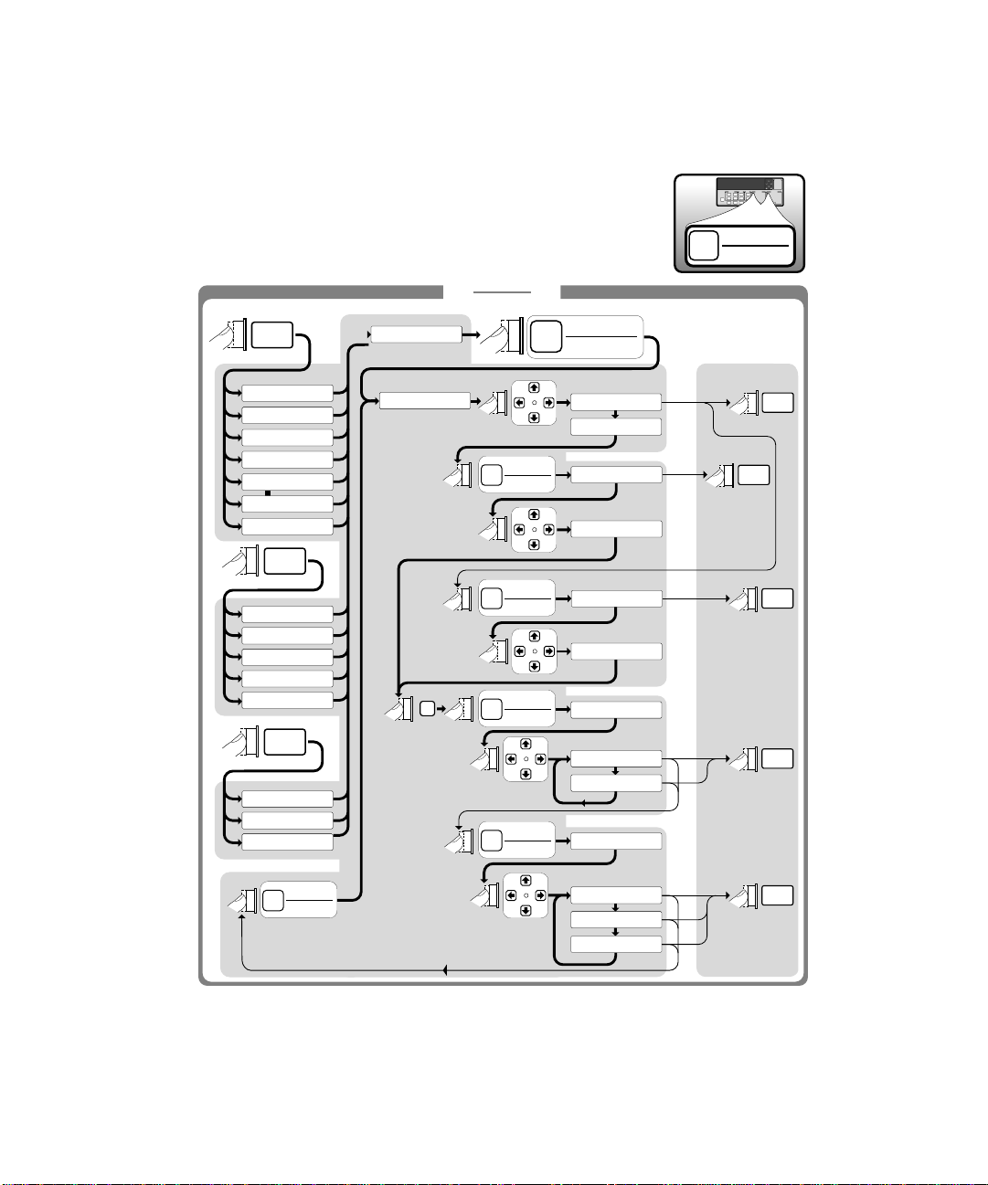
HP 53131A/132A Quick Reference Guide
The Quick Reference Guide is designed for experienced users of the
HP 53131A/132A Universal Counter. It is intended to be used as a tool to
trigger your memory. If you are using the HP 53131A/132A for the first
time, HP recommends that you at least read Chapter 1, “Getti ng St art ed,”
in the Operating Gui de first.
The Quick Reference Guide follows this page, and consists of the following
items:
• Menu Trees which may be torn out of the guide for external use
(pages 1, 2, 3a, and 3b).
• Menu Roadmaps which illustrate via key-press sequences how to
navigate through the menus under the menu keys (pages 4
through 11). Key-press sequences are provided for the following
menu keys:
– Freq & Ratio
– Time & Period
–Other Meas
– Gate & ExtArm
– Uppr & Lower
– Limit Modes
– Scale & Offset
–Stats
– Trigger/Sensitivity
Operating Guide xxiii
Page 26

xxiv Operating Guide
Page 27

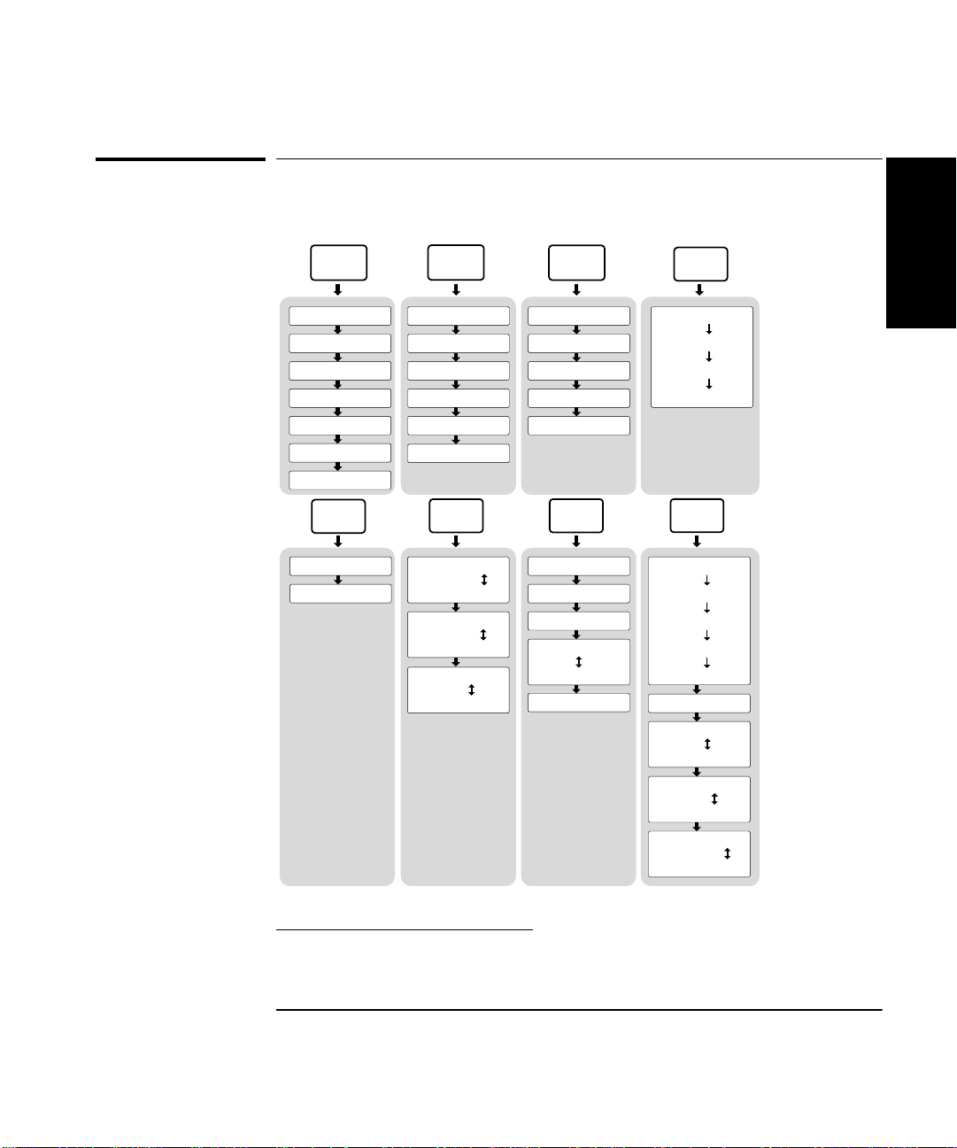
HP 53131A/132A
Universal Counter
Freq &
Ratio
FREQUENCY 1
FREQUENCY 2
FREQUENCY 3
RATI O 1 TO 2
RATI O 1 TO 3
RATI O 2 TO 1
RATI O 3 TO 1
Uppr &
Lower
UPPR: 0.000000
LOWR: 0.000000
Time &
Period
T I 1 TO 2
PERIOD 1
RISETIME 1
FALLTIME 1
POS WIDTH 1
NEG WIDTH 1
Limit
Modes
LIM TEST: OFF
LIM TEST: ON
ON FAIL:GO ON
ON FAIL: STOP
SHOW: NUMBER
SHOW: GRAPH
Scale &
Offset
SCALE:1.000000
OFFS: 0.000000
SET OFFSET ?
MATH: OFF
MATH: ON
MATH HELP?
Other
Meas
T O T A L I Z E 1
PHASE 1 TO 2
DUTYCYCLE 1
VOLT PEAKS 1
VOLT PEAKS 2
Stats
SHOW: MEAS
SHOW: STD DEV
SHOW: MEAN
SHOW: MAX
SHOW: MIN
N: 100
STATS: OFF
STATS: ON
USE: ALL MEAS
USE: IN LIMIT
ON SINGLE: 1
ON SINGLE: N
(HP 53131A and HP 53132A)
1
Page 28

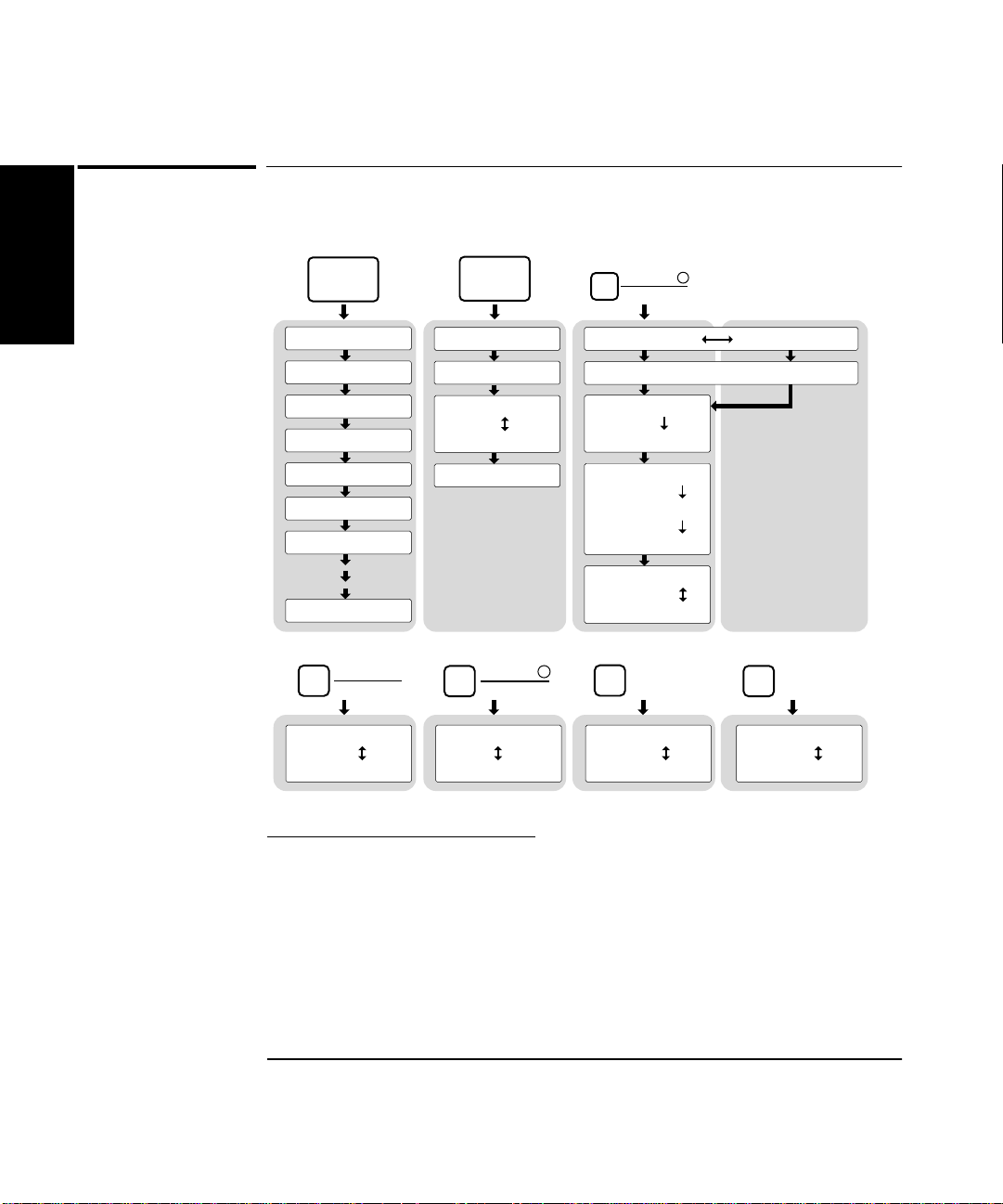
HP 53131A/132A
Universal Counter
Recall
NO REGISTERS
RECALL 0
RECALL 1
RECALL 2
RECALL 3
RECALL 4
RECALL 5
RECALL 20
50Ω
1MΩ
CH 1: 50 OHM
CH 1: 1M OHM
Save &
Print
SAVE:
UNSAVE:
PRINT: OFF
PRINT: ON
PRINT HELP?
DC
AC
CH 1: DC
CH 1: AC
Trigger
Sensitivity
AUTO TRG: ON AUTO TRG: OFF
LEVEL: 50 PCT
SLOPE: POS
SLOPE: NEG
SENSTVTY: HI
SENSTVTY: LO
SENSTVTY:MED
COMMON 1: OFF
COMMON 1: ON
X10
Attenuate
CH 1: X10 ATT
CH 1: X1 ATT
LEVEL: 0.000V
SLOPE: POS
SLOPE: NEG
SENSTVTY: HI
SENSTVTY: LO
SENSTVTY:MED
COMMON 1: OFF
COMMON 1: ON
100kHz
Filter
CH 1: LP FILT
CH 1: NO FILT
(HP 53131A and HP 53132A)
2
Page 29

HP 53131A and
HP 53132A
(Serial Number Prefix below 3646)
Universal Counter
Gate &
ExtArm
Time &
Period
T I 1 TO 2
-- -- -- -- -- -- -- -- -- -- -- --
Gate &
ExtArm
ARM: AUTO
DELAY : NONE
DELAY : TIME
T IME : .01000
GATE: TIME
TIME: .100 s
ARM : EXTERNL
SLOPE : POS
DELAY: NONE
GATE: AUTO
SLOPE : NEG
DELAY: TIME
TIME : .01000
START: POS
START: NEG
STOP: AUTO
STOP: NEG
STOP: POS
STOP: TIME
TIME: .100 s
GATE: DIGITSGATE: EXTERNL
DIGITS: 4
(HP 53131A and HP 53132A S/N below 3646)
3a
Page 30

HP 53132A
(Serial Number Prefix 3646 and above)
Universal Counter
Time &
Period
T I 1 TO 2
-- -- -- -- -- -- -- -- -- -- -- --
Gate &
ExtArm
GATE: TIME
TIME: .100 s
GATE: AUTO
Gate &
ExtArm
START: POS
START: NEG
STOP: AUTO
STOP: NEG
STOP: POS
STOP: TIME
TIME: .100 s
GATE: DIGITSGATE: EXTERNL
DIGITS: 4
START: AUTO
DELAY : NONE
T : .1 E : 1
DELAY :TIME
DELAY : EVENT
SLOPE : POS
DELAY: NONE
STOP : AUTO
DELAY : NONE
DELAY: TIME
T : .1 E : 1
SLOPE : POS
T : .1 E : 1
(HP 53132A S/N 3646 and above)
3b
START: EXT
SLOPE : NEG
STOP : EXT
DELAY : TIME
DELAY: EVENT
SLOPE : NEG
DELAY : EVENT
Page 31

HP 53131A/132A
Universal Counter
Freq &
Ratio
MEASURE
Time &
Period
Other
Meas
Freq &
Ratio
Freq &
Ratio
Freq &
Ratio
Freq &
Ratio
Freq &
Ratio
Freq &
Ratio
Freq &
Ratio
Freq &
Ratio
FREQUENCY 1
FREQUENCY 2
FREQUENCY 3
RATIO 1 TO 2
RATIO 1 TO 3
RATIO 2 TO 1
RATIO 3 TO 1
Time &
Period
Time &
Period
T I 1 TO 2
1
Time &
PERIOD 1
Period
Time &
RISETIME 1
Period
Time &
FALLTIME 1
Period
Time &
POS WIDTH 1
Period
Time &
NEG WIDTH 1
Period
Other
Meas
Other
Meas
TOTALIZE 1
Other
PHASE 1 TO 2
Meas
Other
DUTYCYCLE 1
Meas
Other
VOLT PEAKS 1
Meas
Other
VOLT PEAKS 2
Meas
(HP 53131A and HP 53132A)
4
Page 32

HP 53131A/132A
Universal Counter
Freq &
Ratio
FREQUENCY 1
MEASURE
– – – – – – – – – – – –
Gate &
ExtArm
Gate &
ExtArm
GATE: TIME
GATE: AUTO
GATE: EXTERNL
Gate &
ExtArm
Gate &
ExtArm
GATE: DIGITS
STOP:
TIME: .100
Gate &
TIME: .100
ExtArm
TIME: .200
Gate &
START:
ExtArm
START: POS
START: NEG
STOP: AUTO
STOP: NEG
STOP: POS
STOP: TIME
TIME: .2000
Gate &
DIGITS: 10
ExtArm
Enter
Enter
Gate &
ExtArm
Gate &
ExtArm
Gate &
ExtArm
RUN
RUN
RUN
DIGITS: 5
(HP 53131A and HP 53132A)
5
Enter
RUN
Page 33

HP 53131A and
HP 53132A
(Serial Number Prefix below 3646)
Universal Counter
Time &
Period
TI 1 TO 2
MEASURE
– – – – – – – – – – – –
Gate &
ExtArm
Gate &
ExtArm
Gate &
ExtArm
ARM:
Gate &
ExtArm
Gate &
ExtArm
Gate &
ExtArm
SLOPE:
DELAY:
TIME: .01000
ARM: AUTO
ARM: EXTERNL
SLOPE: POS
SLOPE: NEG
DELAY: NONE
DELAY: TIME
TIME: .02000
RUN
RUN
RUN
RUN
Enter
(HP 53131A and HP 53132A S/N below 3646)
6a
Page 34

HP 53132A
(Serial Number Prefix 3646 and above)
Universal Counter
Time &
Period
TI 1 TO 2
MEASURE
- - - - - - - - - - -
Gate &
ExtArm
Gate &
ExtArm
START:
Gate &
ExtArm
SLOPE:
START: EXT
START: AUTO
Gate &
ExtArm
SLOPE: POS
SLOPE: NEG
Gate &
DELAY:
ExtArm
DELAY :NONE
DELAY :TIME
DELAY :EVENT
Gate &
T : .1
ExtArm
T : 100.1
Gate &
E : 1
ExtArm
E : 1000
A
Enter
Enter
B C
(HP 53132A S/N 3646 and above)
6b
Page 35

HP 53132A
(Serial Number Prefix 3646 and above)
Universal Counter
Gate &
ExtArm
A
Gate &
ExtArm
STOP :
STOP :EXT
B C
STOP :AUTO
Gate &
SLOPE :
ExtArm
SLOPE : POS
SLOPE : NEG
Gate &
DELAY :
ExtArm
DELAY :NONE
Run
DELAY :TIME
DELAY :EVENT
Gate &
ExtArm
Gate &
ExtArm
T : .1
T : 100.1
E : 1
E : 1000
Run
Enter
Run
Enter
(HP 53132A S/N 3646 and above)
6c
Page 36

HP 53131A/132A
Universal Counter
Uppr &
Lower
LIMITS
Uppr &
Lower
Limit
Modes
Uppr &
Lower
Limit
Modes
Limit
Modes
UPPR: 0.000000
Uppr &
LOWR: 0.000000
Lower
LIM TEST:
Limit
ON FAIL:GO ON
Modes
Limit
SHOW: NUMBER
Modes
UPPR: 5.100000
LOWR: 4.900000
LIM TEST: OFF
LIM TEST: ON
ON FAIL:GO ON
ON FAIL: STOP
SHOW: NUMBER
SHOW: GRAPH
Enter
Enter
RUN
RUN
RUN
RUN
RUN
(HP 53131A and HP 53132A)
7
Page 37

HP 53131A/132A
Universal Counter
Scale &
Offset
Scale &
Offset
MATH
Scale &
Offset
Scale &
Offset
Scale &
Offset
Scale &
Offset
Scale &
Offset
SCAL: 1.000000
OFFS: 0.000000
SET OFFSET?
MATH:
MATH HELP ?
SCAL: 2.000000
OFFS: 0.500000
Enter
OFFS:-nnnnnnn
MATH: OFF
MATH: ON
Enter
(MEAS X SCALE) + OFFS = RESULT
Enter
Enter
RUN
RUN
RUN
RUN
(HP 53131A and HP 53132A)
8
Page 38

HP 53131A/132A
Universal Counter
Stats
Stats
MATH
Stats
SHOW:
SHOW: MEAS
SHOW: STD DEV
SHOW: MEAN
SHOW: MAX
SHOW: MIN
Stats
Stats
Stats
Stats
N: 100
N: 200
STATS:
STATS: OFF
STATS: ON
USE:
USE: ALL MEAS
USE: IN LIMIT
ON SINGLE:
ON SINGLE: 1
ON SINGLE: N
Enter
RUN
RUN
Run
Run
(HP 53131A and HP 53132A)
9
Page 39
HP 53131A/132A
Universal Counter
Freq &
Ratio
– – – – – – – – – – – –
Trigger
Sensitivity
CHANNEL 1
CHANNEL 2
Trigger
Sensitivity
FREQUENCY 1
FREQUENCY 2
FREQUENCY 3
RATIO 1 TO 2
RATIO 1 TO 3
RATIO 2 TO 1
RATIO 3 TO 1
Time &
Period
PERIOD 1
RISETIME 1
FALLTIME 1
POS WIDTH 1
NEG WIDTH 1
Other
Meas
TOTALIZE
PHASE 1 TO 2
DUTY CYCLE 1
Trigger
Sensitivity
AUTO TRG:
Enter
Trigger
Sensitivity
Trigger
Sensitivity
Trigger
Sensitivity
Trigger
Sensitivity
AUTO TRG: ON
AUTO TRG: OFF
LEVEL: 0.000V
LEVEL: 2.000V
LEVEL: 50 PCT
LEVEL: 75 PCT
SLOPE:
SLOPE: POS
SLOPE: NEG
SENSTVTY:
SENSTVTY: HI
SENSTVTY: LO
SENSTVTY: MED
RUN
RUN
RUN
RUN
RUN
(HP 53131A and HP 53132A)
10
Page 40

HP 53131A/132A
Universal Counter
Time &
Period
TI 1 TO 2
CHANNEL 1
CHANNEL 2
– – – – – – – – – – – –
Trigger
Sensitivity
Trigger
Sensitivity
Trigger
Sensitivity
Trigger
Sensitivity
Trigger
Sensitivity
Trigger
Sensitivity
Trigger
Sensitivity
Trigger
Sensitivity
AUTO TRG:
LEVEL: 0.000V
LEVEL: 50 PCT
SLOPE:
SENSTVTY:
COMMON 1:
AUTO TRG: ON
AUTO TRG: OFF
LEVEL: 2.000V
LEVEL: 75 PCT
SLOPE: POS
SLOPE: NEG
SENSTVTY: HI
SENSTVTY: LO
SENSTVTY: MED
COMMON 1: OFF
COMMON 1: ON
RUN
RUN
Enter
RUN
RUN
RUN
RUN
(HP 53131A and HP 53132A)
11
Page 41

1
Getting Started
Page 42

Chapter 1 Getting Started
The Front Panel at a Glance
The Front Panel at a Glance
1
Remote
SRQ
POWER
Utility Menu:
Hold at power up
8
14
1
53131 A
UNIVERSAL COUNTER
Period Freq +Wid -Wid Rise Fall Time Ch 1 Ch 2 Ch 3 ExtRef
MEASURE LIMITS MATH CHANNEL 1 CHANNEL 2
Freq &
Ratio
Other
Meas
Recall
Time &
Period
Gate &
ExtArm
LocalUtility
Save &
Print
9
23
225 MHz
Uppr &
Lower
Limit
Modes
Run
11
10
Scale &
Offset
Stats
Stop/
Single
567
4
MHz
µs
Trigger
Sensitivity
50Ω
1MΩ
DC
AC
X10
Attenuate
Gate
Damage Lvl:
5V rms MAX.50Ω
100kHz
Filter
!
Limit
12 13
+/–
Enter
Trigger
Sensitivity
50Ω
1MΩ
DC
AC
X10
Attenuate
CHANNEL 3
100 MHz − 3 GHz
Damage Lvl:
5V rms MAX.50Ω
Damage Lvl:
5V rms MAX.50Ω
100kHz
Filter
!
!
Note: Unit shown with Option 030.
1 Measurement function menu keys
2 Limits menu keys
3 Math menu keys
4 Sign (+ or −) selection toggle key
5 Data Entry/Select (or arrow) keys
6 Enter numeric data (terminate) key
7 3.0/5.0/12.4 GHz RF input chann el
(optional)
8 Utility menu key (Hold during
power-up to access Utility functions.)
9 Recall, Save and Print menu keys
10 Gate and External Arm menu key
11 Measurement control keys
12 Channel 1 Trigger/Sensitivity menu
key and input conditioning keys
13 Channel 2 Trigger/Sensitivity menu
key and input conditioning keys
14 Calibration menu key (Hold Scale &
Offset key during power-up to access
Calibration functions.)
NOTE
It is normal operation for the fan in the Counter to continue to run after
the Counter is placed in Standby mode. Power to the timebase is
continuous to maintain long term measurement reliability, and the fan
helps maintain timebase temperature stability.
1-2 Operating Guide
Page 43

Chapter 1 Getting Started
Other
Meas
Time &
Period
Freq &
Ratio
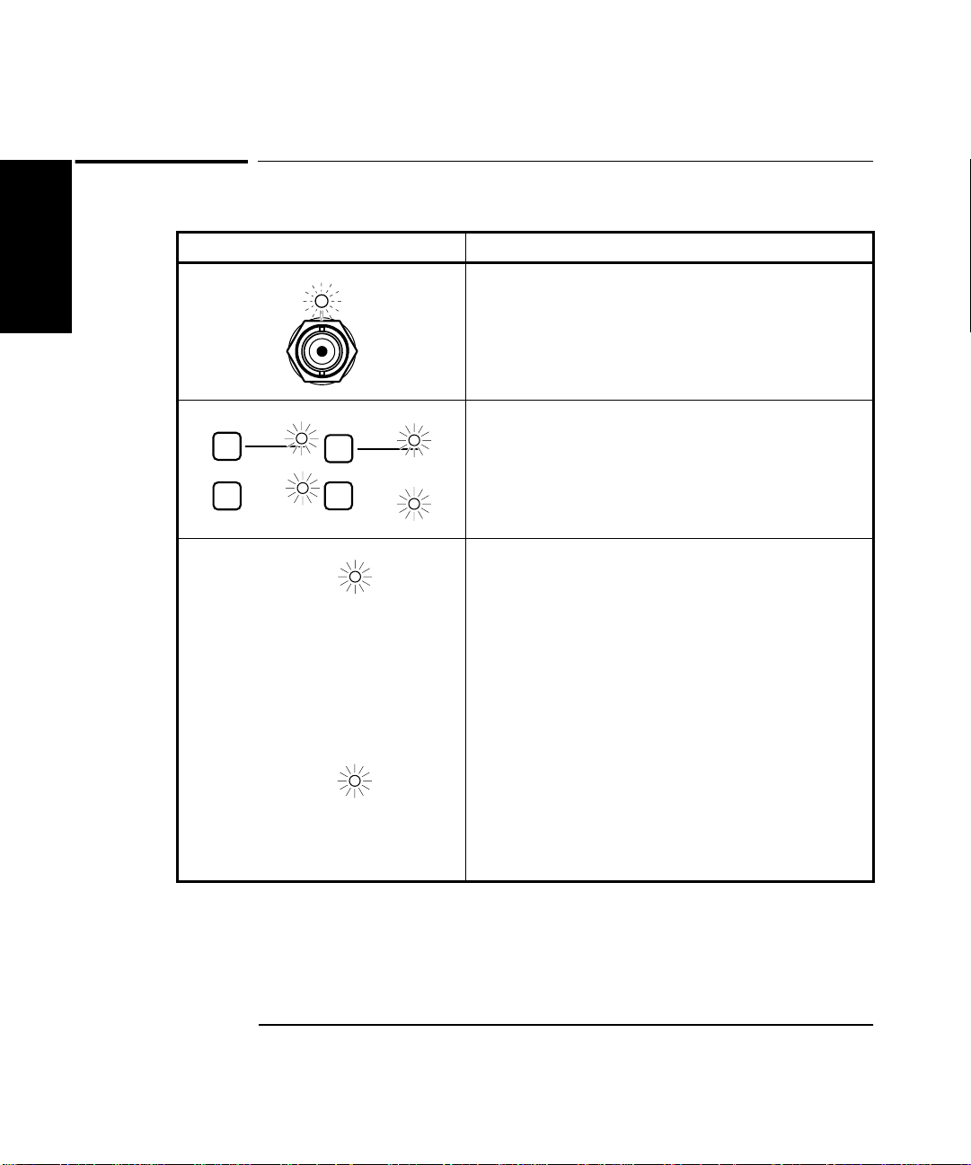
The Front Panel Indicators at a Glance
The Front Panel Indicators at a Glance
There are eight different gro ups of indicato rs or LEDs. They are listed and
described in the following table.
Indicators Description of the Indicators
When one of these indicato rs is lit, it simultaneous ly
indicates which key’s menu (for example, Time &
Period key) and its menu item (for example, TI 1
to 2) is enabled.
When these indicators are lit, the key’s “enable”
Scale &
Offset
Stats
Limit
Modes
Local
Save &
Print
Trigger
Sensitivity
menu item (that is, Limit Modes/LIM TEST,
Scale & Offset/MATH, Stats/STATS, and
Save & Print/PRINT) is enabled.
When this indi cator is lit, i t indica tes that yo u are in
the Trigger/Sensitivity menu for the corresponding
channel.
When this indicator flashes, it indicates that the
arrow keys can be used to modify or enter data.
1
+/–
Enter
When one of these indicators is lit, it indicates that
Run
Stop/
Single
the Run or Single function is enabled.
Operating Guide 1-3
Page 44
Chapter 1 Getting Started
Remote
SRQ
The Front Panel Indicators at a Glance (Cont.)
The Front Panel Indicators at a Glance (Cont.)
1
Indicators Description of the Indicators
When this indicator flashes, it indicates that the
Counter is triggering on the input signal. If the
input signal is too high, this indicator remains ON.
If the input signal is too low, this indicator is OFF.
When one of these indicators is lit, it indicates that
50Ω
1MΩ
X10
Attenuate
DC
AC
100kHz
Filter
the adjacent choice (that is, 50Ω, DC, X10, or
100kHz Filter) is enabled or active. Note that when
these indicators are not lit, then the other choice
(that is, 1MΩ, AC, X1, or no filter) is active.
A lit Remote indicator indicates that the Counter is
in remote mode (No te: In th e remote mo de, the Save
& Print key becomes the Local key.)
If (while in remote) an error occurs, the Remote
indicator will flash. The indi cator will continue
flashing until the controller has read or cleared the
error queue, or until the front panel returns to local
mode.
An unlit Remote indicator indicates that the
Counter is in local mode.
The SRQ indicator indicates that the Counter has
requested service from th e controller. The SRQ
indicator will remain lit until the controller has
recognized the service request and serial poll ed the
Counter, or taken specific action to cancel the
request (for example, *CLS command).
1-4 Operating Guide
Page 45
Chapter 1 Getting Started
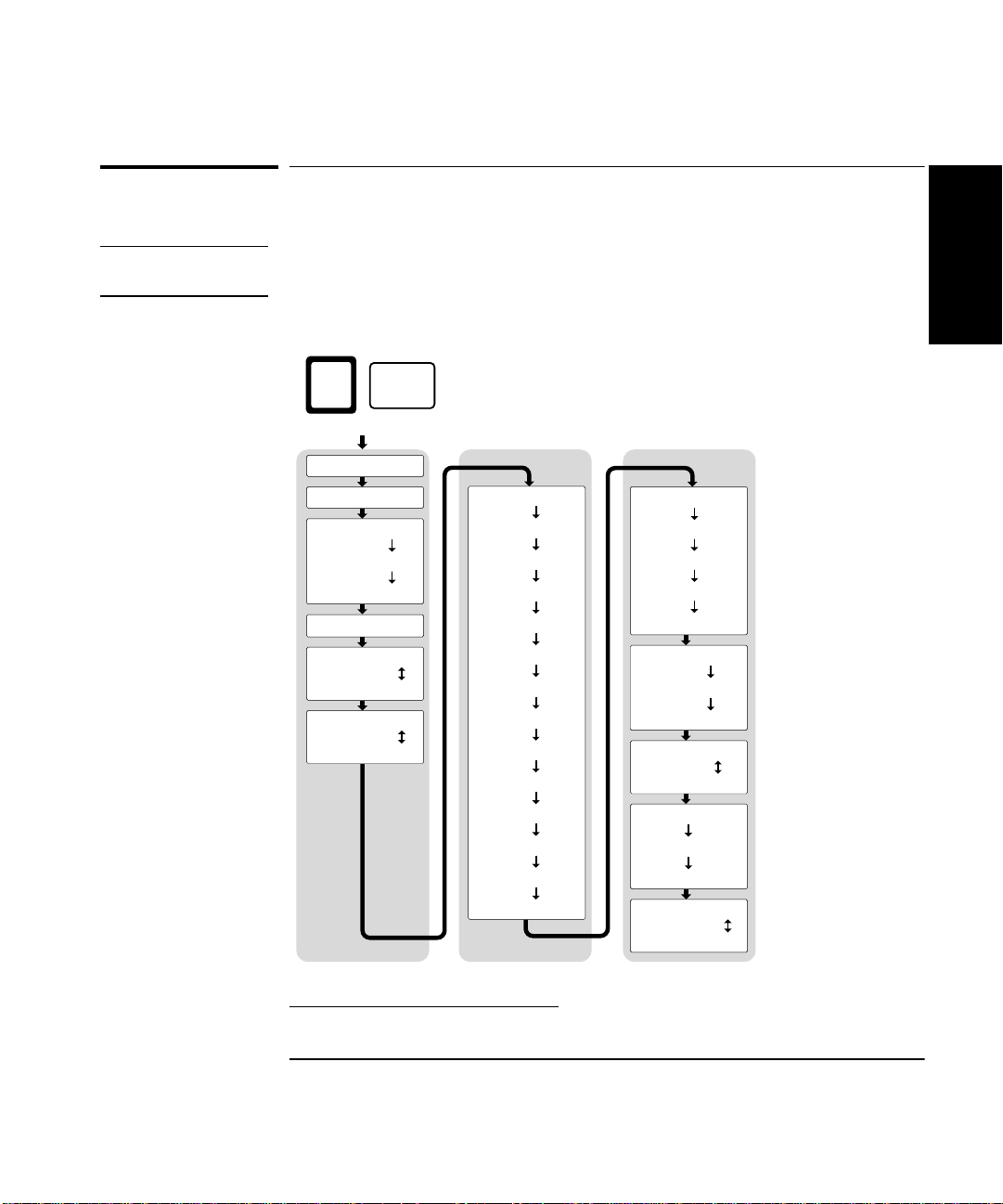
The Front Panel Menus at a Glance
The Front Panel Menus at a Glance
Freq &
Ratio
Time &
Period
Other
Meas
Gate &
ExtArm
1
FREQUENCY 1
FREQUENCY 2
1
FREQUENCY 3
RATI O 1 TO 2
1
RATI O 1 TO 3
RATI O 2 TO 1
1
RATI O 3 TO 1
Uppr &
Lower
UPPR: 0.000000
LOWR: 0.000000
T I 1 TO 2
PERIOD 1
RISETIME 1
FALLTIME 1
POS WIDTH 1
NEG WIDTH 1
Limit
Modes
LIM TEST: OFF
LIM TEST: ON
ON FAIL:GO ON
ON FAIL: STOP
SHOW: NUMBER
SHOW: GRAPH
T O T A L I Z E 1
PHASE 1 TO 2
DUTYCYCLE 1
VOLT PEAKS 1
VOLT PEAKS 2
Scale &
Offset
SCALE:1.000000
OFFS: 0.000000
SET OFFSET ?
MATH: OFF
MATH: ON
MATH HELP?
2
GATE: TIME
GATE: AUTO
GATE: EXTERNL
GATE: DIGITS
Stats
SHOW: MEAS
SHOW: STD DEV
SHOW: MEAN
SHOW: MAX
SHOW: MIN
N: 100
STATS: OFF
STATS: ON
USE: ALL MEAS
USE: IN LIMIT
ON SINGLE: 1
ON SINGLE: N
1
These menu items appear only if your Counter contains the optional Input Channel.
2
Refer to the Menu Tree in the Quick Reference Guide (which precedes this chapter) and/or the Gate/External
Arming table in Chapter 2 for details on the Gate & ExtArm menu.
Operating Guide 1-5
Page 46
Chapter 1 Getting Started
The Front Panel Menus at a Glance (Cont.)
The Front Panel Menus at a Glance (Cont.)
1
Recall
3
NO REGISTERS
4
RECALL 0
RECALL 1
RECALL 2
RECALL 3
RECALL 4
RECALL 5
RECALL 20
50Ω
1MΩ
7
CH 1: 50 OHM
CH 1: 1M OHM
Save &
Print
SAVE:
5
UNSAVE:
PRINT: OFF
PRINT: ON
PRINT HELP?
Trigger
Sensitivity
AUTO TRG: ON
LEVEL: 50 PCT
SLOPE: POS
SLOPE: NEG
SENSTVTY: HI
AUTO TRG: OFF
LEVEL: 0.000V
SENSTVTY: LO
SENSTVTY:MED
6
COMMON 1: OFF
COMMON 1: ON
DC
AC
777
CH 1: DC
CH 1: AC
X10
Attenuate
CH 1: X10 ATT
CH 1: X1 ATT
100kHz
Filter
CH 1: LP FILT
CH 1: NO FILT
3
This appears when nothing can be recalled.
4
Only registers which can be recalled will appear in this menu.
5
This menu item only appears if an instrument setup has been saved.
6
COMMON 1 only appears when the Counter is operating in the Time Interval measurement function
(TI 1 TO 2).
7
Channel 2 is the same, except “CH 2” instead of “CH 1” is displayed. These menus will terminate after
two seconds.
1-6 Operating Guide
Page 47
Chapter 1 Getting Started
The Front Panel Menus at a Glance (Cont.)
The Front Panel Menus at a Glance (Cont.)
NOTE
Turn power off, press and hold Recall (Utility) key, then press POWER
key to access this menu.
POWER
On / Stby
Utility
Recall
REV:
HP-IB: 3
TIMEBAS: AUTO
TIMEBAS: INT
TIMEBAS: EXT
CAL: HELP?
TEST LOOP: OFF
TEST LOOP: ON
TST PRINT:OFF
TST PRINT: ON
TEST: ALL?
8
TEST: DISP?
TEST: CPU?
TEST: ROM?
TEST: RAM?
TEST: EEPROM?
TEST: HP-IB?
TEST: QSPI?
TEST: FPGA?
TEST: FR END?
TEST: MEAS?
TEST: INTERP?
8
TEST: KEYPAD?
TEST: PRINT?
BAUD: 9600
BAUD: 19200
BAUD: 300
BAUD: 1200
BAUD: 2400
PARITY: OFF
PARITY: EVEN
PARITY: ODD
SW PACE: XON
SW PACE: NONE
DTR: HIGH
DTR: LIMIT
DTR: HW PACE
SHOW 9 AS: 9.0
SHOW 9 AS: 9,0
1
8
These menu items appear only if TEST LOOP is OFF.
Operating Guide 1-7
Page 48

Chapter 1 Getting Started
The Front Panel Menus at a Glance (Cont.)
The Front Panel Menus at a Glance (Cont.)
1
NOTE
Turn power off, press and hold Scale & Offset key, then press POWER
key to access this menu. (This menu does not exist in early versions of the
Counter. In the early versions of the Counter, the CAL: menu item resides
in the Utility menu, and there is no calibration security capability.)
POWER
Scale &
Offset
On / Stby
CAL SECURE CAL UNSECURE
9
CAL: OFFS1?
CAL: OFFS2?
CAL: GAIN1?
CAL: GAIN2?
CAL: TI QUIK?
CAL: TI FINE?
CAL: TIMEBAS?
10
CODE: 0
CAL COUNT?
HELP: CAL?
HELP: SECURE?
HELP: CODE?
9
This menu item appears and calibration is permitted only if calibration is unsecure. Enter in the correct code
to change calibration to secure; refer to the section titled “Using the Calibration Menu” in Chapter 2 in this guide
for more information.
10
Timebase can be automatically calibrated only if the timebase option is installed.
1-8 Operating Guide
Page 49

Chapter 1 Getting Started
The Display Annunciators at a Glance
The Display Annunciators at a Glance
MHz
µs
Period Freq +Wid -Wid Rise Fall Time Ch 1 Ch 2 Ch 3 Limit ExtRef
Annunciator Indication
Period Counter is set to mea sur e Period.
Freq Counter is set to mea sur e Fr equency.
+Wid Counter is set to mea sur e Positive Pulse Width.
−Wid C ounter is set to measur e Negative Pulse Width.
Rise Counte r i s set to measure Rise Time. (The Time ann unciator is also
turned on when the R ise annunciator is on.)
Fall Counter is set to mea sur e Fa ll Time. (The Time annunci at or is al so
turned on when Fall annunciator is on.)
Time Counter is set to mea sur e Time Inte rval. (The Time annunciator is
also turned on when the R i se or Fa l l an nun ci at or ar e on.)
Ch 1 Counter’s channel 1 is selected to measure an input signal.
Ch 2 Counter’s channel 2 is selected to measure an input signal.
Ch 3 Counter’s channel 3 is selected to measure an input signal.
Limit Counter is limit te st ing and the current mea surement exceeds th e
user-entered limits.
ExtRef Counter is se t to use the signal connect ed at rear panel Ref In
connector as the timebase (TIMEBAS: EXT); or Counte r is set to
automatically (TIMEBAS: AUTO) select the timebase and has chosen
the signal connected at th e rear panel Ref In connector.
Hz The displayed data is in units of Hertz.
M The prefix for the units of th e displayed data is mega (10
µ The prefix for the units of th e displayed data is micro (10
s The displayed data is in units of seconds.
Gate The gat e is open. Before a measurement starts, this annunciat or is
OFF, indicating the gate is closed. During a measurement, the
annunciator is ON, indi cating the gate is open.
Gate
6
).
−6
).
1
Operating Guide 1-9
Page 50
Chapter 1 Getting Started
or
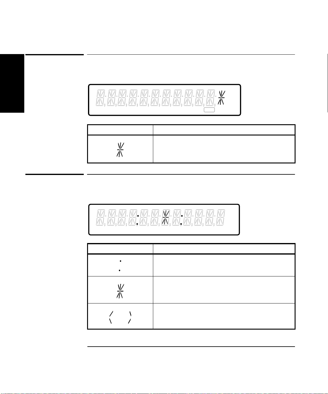
The Display Special Character at a Glance
The Display Special Character at a Glance
1
MHz
µs
Period Freq +Wid -Wid Rise Fall Time Ch 1 Ch 2 Ch 3 Limit ExtRef
Special Character Description
A placeholder that indicates this digit is not
significant.
Gate
The Limit Test Graph Characters at a Glance
Freq Ch 1
Special Character Description
The colons represent the lower and upper limits.
The asterisk represents the last measurement.
These marks indicate that the last measurement was
significantly past the limit i n the direction indicated.
1-10 Operating Guide
Page 51

Chapter 1 Getting Started
The Rear Panel at a Glance
The Rear Panel at a Glance
1
1 2
WARNING:
1
I
N
P
U
T
Ext
S
Arm
WARNING:
NO OPERATOR SERVICEABLE PARTS INSIDE, REFER SERVICING TO SERVICE TRAINED PERSONNEL.
50/60 Hz
50/60/400 Hz
60 VA
100 - 120 VAC
200 - 240 VAC
10 MHz Out
AC LINE:
2
3
!
Ref
In
FOR CONTINUED FIRE PROTECTION, USE SPECIFIED ~ LINE FUSE.
4
5 6 7 8 9
1 Rear-panel input connectors
(optional)
2 Power module (Senses incoming
voltage and automa tically
selects proper setup.)
3 Fan
4 External Arm input connector
5 External Reference Input connector
3
ISM 1-A
FOR LABORATORY USE BY
QUALIFIED PERSONNEL
FOUR USAGE EN LABORATOIRE
PAR PERSONNEL QUALIFIE
OPTIONS
001 MS Oven
HP-IB
Talk Only
010 HS Oven
To Configure:
Hold Recall during turn-on.
92
Osc Adjust
RS - 232
6 10 MHz Output connector
7 HP-IB (IEEE-488.1)
interface connector
8 Oscillator Adjust potentiometer
(This potentiometer is not present
for options 001, 010, and 012.)
9 RS-232 interface or Limit
Output connector
SERIAL PLATE
NOTE
It is normal operation for the fan in the Counter to continue to run after
the Counter is placed in Standby mode. Power to the timebase is
continuous to maintain long term measurement reliability, and the fan
helps maintain timebase temperature stability.
Operating Guide 1-11
Page 52

Chapter 1 Getting Started
Making Measurements
Making Measurements
1
One of the first things you will want to do wi th your HP 53131A/132A
Universal Counter is to become acquainted with its front panel. Therefore,
we have written the procedures in this section to familiarize you with
some of its controls. The following procedures are provided:
• First you are shown how to turn on the Counter and measure the
frequency of a signal applied to the Counter’s input channels.
• Second, you are shown how to use the input coupling, impedance, and
trigger/sensitivity keys to set the input conditions of the appropriate
input channel to match the signal being measured.
• Third, you are shown how to scale and offset the measurement result.
• Fourth, you are shown how to set upper and lower limits for
measurements.
• Fifth, you are shown how to enable the Counter to compute statistics
(such as standard deviation) and display statistics of measurements.
• Last, you are shown how to use the Run and Stop/Single keys to
control measurements.
The order of the procedures in this chapter is the recommended order for
making measurements with this Counter.
Study and refer to the following legend, as needed, to understand the
meaning of the icons which are used throughout this chapter.
1-12 Operating Guide
Page 53

Chapter 1 Getting Started
Making Measurements
Legend
12
34
1 Press key one time
and release
2 Press key two times
and release
4 Press and hold
5 Result
6 Auto operation
7 Connect signal
3 Repeated key presses
To Measure Frequency
POWER
On / Stby
Period Freq +Wid -Wid Rise Fall Time Ch 1 Ch 2 Ch 3 Limit ExtRef
5
6
78
91110
1
8 Disconnect signal
9 Indicator off
10 Indicator on
11 Indicator flashing
MHz
µs
Gate
Freq Ch 1
Freq Ch 1
Operating Guide 1-13
Page 54

Chapter 1 Getting Started
Other
Meas
Time &
Period
Gate &
ExtArm
MEASURE
Freq &
Ratio
Making Measurements
NOTE
Earlier versions of the Counter do not momentarily display the HP-IB
address at turn-on.
1
Connect (for demonstration purposes) the Counter’s rear-panel 10 MHz
Out signal to CHANNEL 1 input as shown in the illustrated procedure,
below.
CHANNEL 1
MHz
Damage Lvl:
5V rms MAX.50Ω
!
Freq Ch 1
Gate
The Counter will automatically display the measured frequency of the
input signal.
Disconnect the demonstration signal from CHANNEL 1, and connect it to
CHANNEL 2 as shown in the following steps.
CHANNEL 1
!
Damage Lvl:
5V rms MAX.50Ω
CHANNEL 2
Damage Lvl:
5V rms MAX.50Ω
Freq &
Ratio
Freq &
Ratio
!
Freq Ch 1
Freq Ch 1
Freq Ch 2
Freq
Ch 2
MHz
Gate
1-14 Operating Guide
Page 55

Chapter 1 Getting Started
CHANNEL 2
Trigger
Sensitivity
DC
AC
50Ω
1MΩ
X10
Attenuate
100kHz
Filter
Damage Lvl:
5V rms MAX. 50Ω
!
Making Measurements
Again, the Counter will automatically display the measured frequency of
the input signal.
If you need or want to change CHANNEL 2’s coupling, impedance, and
triggering conditions to match the input signal you are trying to measure,
the next procedures “To Select Input Coupling and Impedance” and
“To Set Input Channel Trigger Level/Sensitivity” demonstrate this.
Perform these procedures whether or not you want to customize the
Counter’s input conditions to measure your signal; doing this will help you
become familiar with the DC/AC, 50Ω/1MΩ, and Trigger/Sensitivity
keys.
To Select Input Coupling and Impedance
Remember, the input signal is still connected to CHANNEL 2.
Selecting Input Coupling
DC
AC
Channel 2’s input coupling is now set to dc.
If you want to change the coupling back to the default ac coupling, perform
the following step.
1
DC
AC
Operating Guide 1-15
Page 56

Chapter 1 Getting Started
Making Measurements
Selecting Input Impedance
50Ω
1
Channel 2’s input impedance is now set to 50Ω.
1MΩ
NOTE
The “arrow” keys can also be used to toggle the state of toggle keys
(DC/AC, 50Ω/1MΩ, etc.) as indicated by the flashing indicator withi n the
arrow keys. However, for simplicity in this procedure, use the
corresponding toggle key to change states.
If you want to change the input impedance back to the default
1MΩimpedance, perform the following step.
50Ω
1MΩ
MHz
Freq
Ch 2
Gate
1-16 Operating Guide
Page 57

Chapter 1 Getting Started
Enter
+/–
Making Measurements
To Set Input Channel Trigger Level/Sensitivity
Changing Trigger Mode
Trigger
Sensitivity
Press any one of these arrow keys to toggle to the next state of
Auto Trigger.
Modifying Input Trigger Level
1
NOTE
Trigger
Sensitivity
The leftmost “0” digit in the LEVEL display is highlighted, indicating that
if you press the d key once the displayed value will increase to 1.000 volt
as shown in the following step.
Enter
BE SURE to always press the Enter key to complete numeric data
entries.
Channel 2’s trigger level is now set to +1V.
Operating Guide 1-17
Page 58

Chapter 1 Getting Started
Making Measurements
To set the trigger level to −0.05V, perform the following steps.
1
+/–
Enter
NOTE
BE SURE to always press the Enter key to complete numeric data
entries.
Channel 2’s trigger level is now set to −0.05V.
Selecting Input Trigger Slope
Trigger
Sensitivity
Display 1, 7/13/92
Display 1, 7/13/92
1-18 Operating Guide
Page 59

Chapter 1 Getting Started
Making Measurements
Selecting Input Sensitivity
Trigger
Sensitivity
Display 1, 7/13/92
Display 1, 7/13/92
Display 1, 7/13/92
Starting the Measurement
Run
Freq
Ch 2
The Run key initiates repetitive measurements, and is described in the
section titled “To Control Measurement” at the end of this chapter.
MHz
Gate
To Select Scale and Offset
1
The Scale & Offset key allows for multiplication and addition,
respectively, of the measurement by user-specified constants.
Modification of the displayed measurement by these Math operations is
represented by the following equation:
(Measurement × Scale) + Offset = Displayed Results
The Scale and Offset Math operations can be used, for example, to
subtract systematic errors or display the percentage difference between
signals.
Operating Guide 1-19
Page 60
Chapter 1 Getting Started
Stats
Scale &
Offset
MATH
Making Measurements
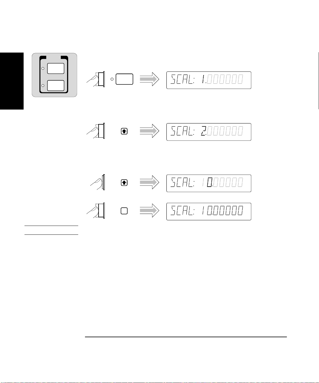
Entering the Scale Value
Scale &
1
To demonstrate the Scale Math operation, set Scale to 10 as shown in the
following steps.
Press and hold the d key until the value of Scale is 10 as shown in the
following step.
Offset
NOTE
Enter
BE SURE to press the Enter key to enter the val ue of 10.
The Scale is now set to 10, and MATH has been enabled.
The Scale & Offset indicator is now lit to show that MATH is enabled.
Since MATH is enabled, the results are being scaled and offset.
1-20 Operating Guide
Page 61
Chapter 1 Getting Started
Making Measurements
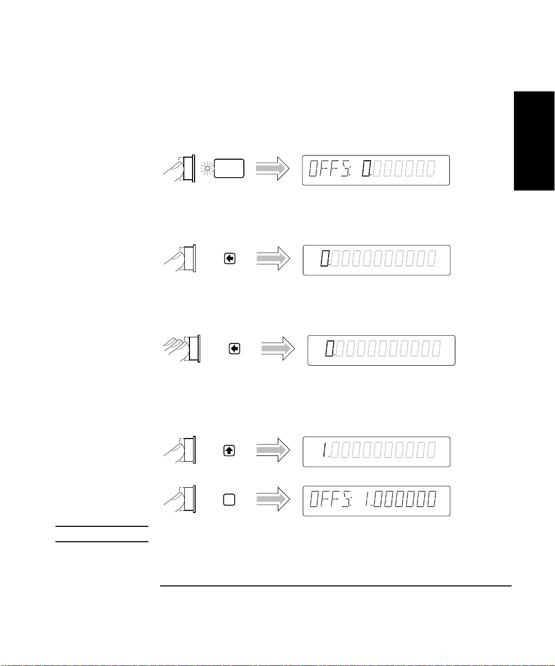
Entering the Offset Value
To demonstrate the Offset Math operation, set the Offset to 1 MHz as
shown in the following steps.
Scale &
Offset
At this point, pressing the s key will cause the Counter to display the full
display of the Offset value as shown in the following step.
Press the s key six more times to cause the Counter to display your entry
in Mega units as shown in the following step.
1
NOTE
M
The leftmost “0” digit in the OFFSet display is highlighted, indicating that
if you press d key once the displayed value will increase to 1 Mega
(that is, 1E6) as shown in the followi ng step.
M
Enter
M
BE SURE to press the Enter key to enter the 1 Mega value.
The Offset is now set to 1 Mega.
Operating Guide 1-21
Page 62

Chapter 1 Getting Started
Making Measurements
Displaying the Math Results
1
Run
Freq Ch 2
M
The Counter displays t he mo difi ed measu rement res ul ts, whi ch are ba sed
on the scale and offset values that you selected in the previous steps.
That is, the 101 represents the original 10, scale multiplied by 10, then
offset by 1.
(For more details and real applications of the Math Scale and Offset
operations, refer to the appropriate section in Chapter 2, “Operating Your
Universal Counter.”)
Disabling Math
Scale &
Offset
Display 1, 7/13/92
Display 1, 7/13/92
Note that the Scale & Offset key indicator is now off.
NOTE
Run
Freq
Ch 2
MHz
Gate
DO NOT cycle POWER because you will need to use these Scale and
Offset values in the follow ing procedure “To Set Limits of Measu rements.”
Continue to the following procedure.
1-22 Operating Guide
Page 63

Chapter 1 Getting Started
Making Measurements
To Set Limits of Measurements
To demonstrate how Math and Limits work together, use the Scale (10)
and Offset (1 Mega) values selected in the previous procedure “To Select
Scale and Offset.” Enable Math by performing the following steps.
Scale &
Offset
Display 1, 7/13/92
Display 1, 7/13/92
1
Run
Freq Ch 2
M
The result of this Math operation is a measurement of 101 MHz.
(Measurement × Scale) + Offset = Result
(10 MHz × 10) + 1Mega = 101 Mega
Now, set the upper limit to 102 Mega and the lower limit to 100 Mega by
performing the following procedures. (Figure 1-1 and Figure 1-2 illustrate
the limits settings.)
Operating Guide 1-23
Page 64

Chapter 1 Getting Started
Limit
Modes
Uppr &
Lower
LIMITS
Making Measurements
Setting the Upper Limit
1
Uppr &
Lower
Press the s key six more times to cause the Counter to display your entry
in Mega units as shown in the following step.
M
M
The leftmost “0” digit in the UPPR display is highlighted as shown above,
indicating that each press of the d key will increase the displayed value.
1-24 Operating Guide
Page 65

Chapter 1 Getting Started
Making Measurements
M
1
M
M
NOTE
Enter
M
BE SURE to press the Enter key to enter the 102 Mega value.
1
2
1 102 Mega Upper Limit
2 101 Mega Scale/Offset M ea sur em ent
Figure 1-1. 102 Mega Upper Limit Setting
Operating Guide 1-25
Page 66
Chapter 1 Getting Started
Making Measurements
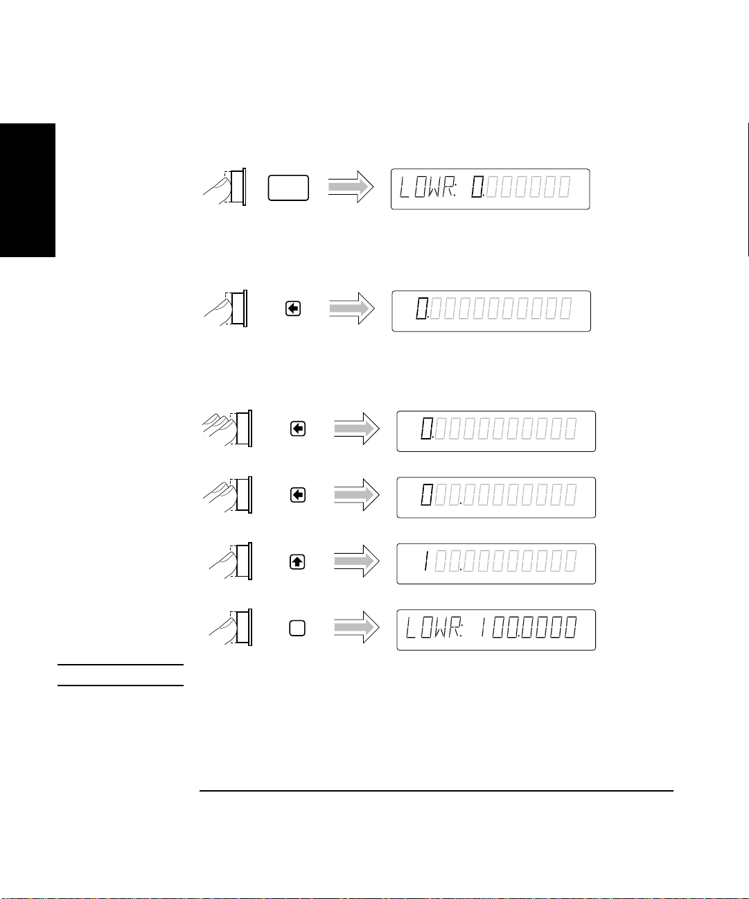
Setting the Lower Limit
1
Uppr &
Lower
Press the arrow keys as shown in th e foll owing steps to set th e lower limi t
value.
Press the s key six more times to cause the Counter to display your entry
in Mega units as shown in the following step.
M
M
M
NOTE
Enter
M
BE SURE to press the Enter key to enter the 100 Mega value.
1-26 Operating Guide
Page 67
Chapter 1 Getting Started
Making Measurements
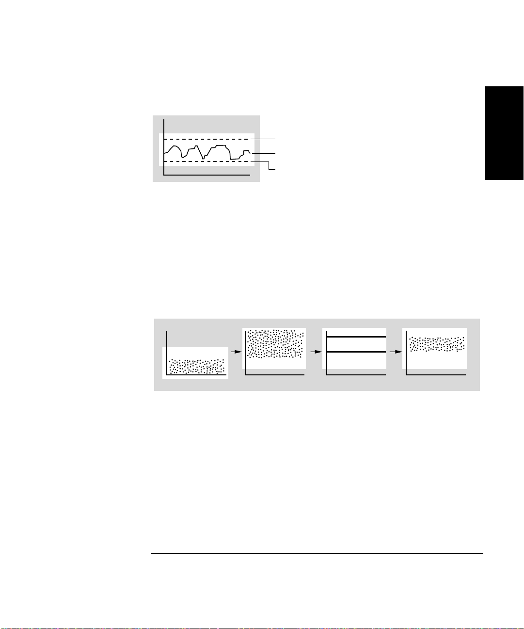
Limits should now be set as shown in Figure 1-2.
1
2
3
1 102 Mega Upper Limit
2 101 Mega Scale/Offset M ea sur em ent
3 100 Mega Lower Limit
Figure 1-2. 100 Mega Lower and 102 Mega Upper Limits Settings
Figure 1-3 represents what transpired during this Math and Limits
procedure.
1
1
234
1 Raw Measurements
2 Math
3 Limits
4 Measurements (Scale/Off set Results)
within Limits
Figure 1-3. Math and Limits Results
Operating Guide 1-27
Page 68

Chapter 1 Getting Started
Making Measurements
Setting the Counter to Flag and Stop Measuring On
Out-of-Limit Measurements
If you want the Counter to stop measuring when the signal exceeds the
1
limits (102 to 100 Mega) that you entered in the previous procedure,
perform the following steps to select the STOP choice in the ON FAIL
display. (Note that ON FAIL: GO ON is the default state after power-up.)
Limit
Modes
Run
Freq Ch 2
M
Gate
The current modified measurement of the input signal applied to
CHANNEL 2 is displayed.
Since the Counter is now in the stop-on-fail mode, the Limit annunciator
in the display will light and the Counter will stop making measurements
when a measurement exceeds the limits you set.
1-28 Operating Guide
Page 69

Chapter 1 Getting Started
Making Measurements
Setting the Counter to Flag On Limits But Continue Measuring
Perform the following steps to select the GO ON choice in the ON FAIL
display if you want the Counter to continue measuring even though an
measurement result exceeds the limits previously entered.
Limit
Modes
Run
Freq Ch 2
M
Gate
The current modified measurement of the input signal applied to
CHANNEL 2 is displayed.
Since the Counter is now in the go-on-fail mode, the Limit annunciator in
the display will light each time a measurement exceeds the limits you set.
However, the Counter will continue to make measurements.
1
Operating Guide 1-29
Page 70
Chapter 1 Getting Started
Making Measurements
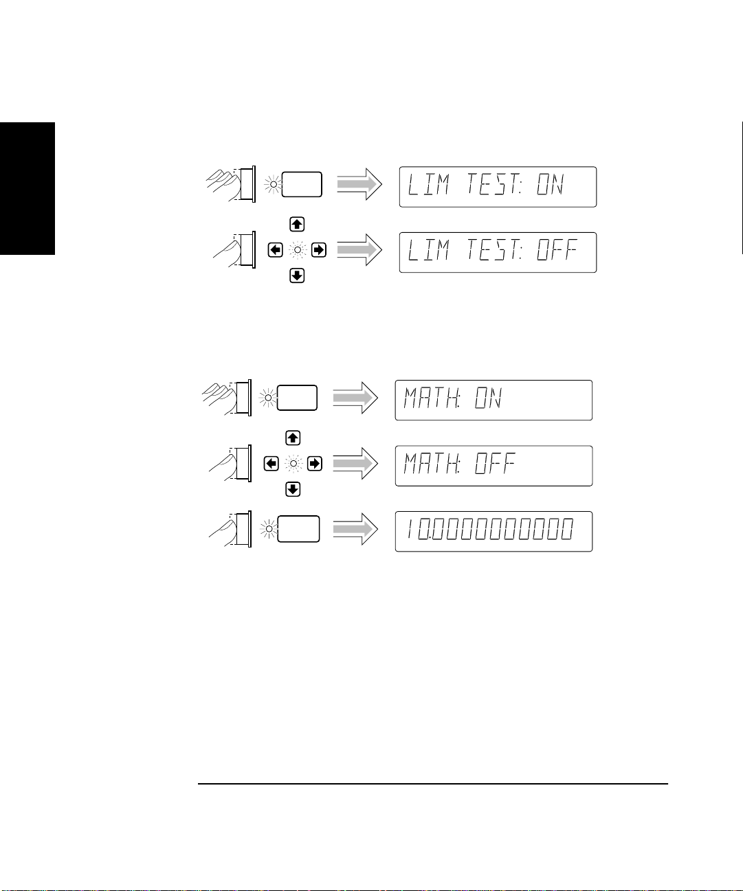
Disabling Limit Testing
Limit
1
Modes
The Counter is now making measurements without limit testing.
Disabling Math
Scale &
Offset
Display 1, 7/13/92
Display 1, 7/13/92
Run
Freq
Ch 2
MHz
Gate
The Counter is now making measurements without the scale/offset values
calculated into the measurements.
1-30 Operating Guide
Page 71

Chapter 1 Getting Started
Stats
Scale &
Offset
MATH
Making Measurements
To Perform Statistics on Measurements
Selecting the Type of Statistics (Stats)
Suppose you want the Counter to compute and display the standard
deviation of the current input data (which is the 10 MHz signal applied
to CHANNEL 2). Also, you want the Counter to make 20 measurements
before it computes the standard deviation. Perform the following steps.
Stats
Updating the SHOW configuration caused Stats to be enabled. The Stats
indicator is now lit.
Stats
1
NOTE
Enter
BE SURE to press the Enter key to enter the val ue of 20.
Operating Guide 1-31
Page 72
Chapter 1 Getting Started
Making Measurements
The Counter is now set to make statistics based on 20 measurements.
Run
1
Freq Ch 2
Freq Ch 2
Freq Ch 2
Hz
Gate
Hz
Gate
In this case, the displayed standard deviation value is computed on all
measurements of the 10 MHz signal since no limits were set.
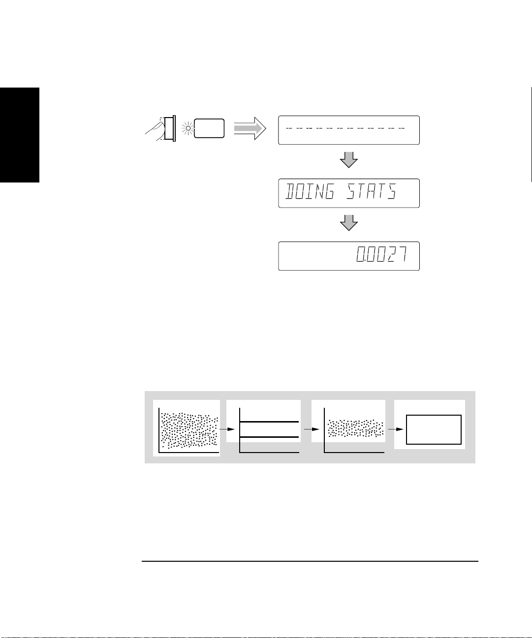
Computing Stats on Filtered Data Only
A special feature of the Counter allows you to use the upper and lower
limits to filter data before statistical processing or computation as shown
in Figure 1-4.
1
2
3
4
1 Raw Measurements
2 Limits
3 Filtered data (USE: IN LIMIT)
4 Statistics
Figure 1-4. Filtering Data Before Statistical Computation
1-32 Operating Guide
Page 73

Chapter 1 Getting Started
Making Measurements
Perform the following steps to select the IN LIMIT choice in the USE
display if you want the Counter to compute statistics on only frequency
measurements within the limits you set.
Stats
Display 1, 7/13/92
Display 1, 7/13/92
Since the Limits were set to 101 Mega and 102 Mega values that are
based on a scale of 10 and offset of 1 Mega, you must re-enable Math now
to get the measurements to be within the limits. Perform the following
steps.
1
Scale &
Offset
Display 1, 7/13/92
Display 1, 7/13/92
Operating Guide 1-33
Page 74

Chapter 1 Getting Started
Making Measurements
Displaying Stats After Filtering Data of Input Signal
Let’s assume you have set the upper and lower limits for the input signal,
and selected the IN LIMIT (filtering) choice. Now, perform the following
1
steps to display the standard deviation of the filtered measurements.
(Note that the first step in the following procedure is optional since you
should have already set Stats to show standard deviation at the beginning
of this Stats procedure. But, you may want to perform the step anyway to
verify that the Counter is displaying the standard deviation of the
measurement.)
Stats
Display 1, 7/13/92
Run
Freq Ch 2
Freq Ch 2
Freq Ch 2
Gate
Gate
The standard deviation value shown in the previous illustration is for
demonstration purposes . The statistic is computed using only those
measurements which fell within the limits you set.
(For more details on the Stats and Limits functions, refer to the
appropriate sections in Chapter 2, “Operating Your Universal Counter.”)
Now, disable Math and Stats as shown in the following procedure.
1-34 Operating Guide
Page 75

Chapter 1 Getting Started
Making Measurements
Disabling Stats and Math
Stats
Scale &
Offset
Display 1, 7/13/92
Display 1, 7/13/92
Run
Freq
Ch 2
MHz
Gate
The Counter is now making and displaying normal measurements
(that is, the Counter is not showing statistics or scale/offset results).
1
Operating Guide 1-35
Page 76

Chapter 1 Getting Started
Run Single/
Stop
Making Measurements
To Control Measurement
Use these two keys to control the measurement of the Counter.
The Run key provides repetitive measurements, whereas the
1
Stop/Single key allows you to make one measurement.
With the 10 MHz signal still connected to CHANNEL 2, perform the
following steps so you can better understand the Run and Stop/Single
operations.
Run
Freq
Ch 2
MHz
Gate
The Counter is now making repetitive measurements (continuously
making “live” measurements).
Stop/
Single
Freq Ch 2
MHz
The Counter stopped making measureme nts. Th e Gate annunciator is not
lit. Hence, pressing the Stop/Single key while the Counter is making
measurements (in Run) causes the Counter to stop after the measurement
in progress is completed. If you press the Stop/Single key again while the
Counter is stopped, the Counter will make a single measurement and then
stop—the Gate annunciator will light one time, momentarily.
If you press the Stop/Single key while the Counter is stopped and when
the Stats menu item ON SINGLE is set to N, the Counter will make
N measurements and then stop. This enables a set of statistics to be
computed.
While the Counter is still stopped, perform the following step.
Run
Freq
Ch 2
MHz
Gate
The Counter is making repetitive measurements again.
1-36 Operating Guide
Page 77

2
Operating Your Universal Counter
Operator’s Reference
Page 78

Chapter 2 Operating Your Universal Counter
Introduction
Introduction
This is the operator’s reference chapter which contains information and
procedures for the front-panel keys, operating functions, and menus of the
HP 53131A/132A 225 MHz Universal Counter.
Chapter Summary
• How this Counter Works for You page 2-4
2
• Using the Measurement Control Keys (Run and
Stop/Single)
• Using Entry/Select (Arrow) Keys page 2-8
• Using the MEASURE Menu Keys page 2-10
• Using the Gate & External Arm Menu Key page 2-16
• Using the MATH Menu Keys page 2-27
• Using the LIMITS Menu Keys page 2-37
• Using CHANNEL 1 and CHANNEL 2 Input
Conditioning Keys
• Using the Save and Recall Menus page 2-52
• Using the Print Menu page 2-56
• Using the Utility Menu page 2-57
• Using the Calibration Menu page 2-67
• Front Panel Display Messages page 2-73
• Preset Values After Power-Up and *RST page 2-78
• Summary of the Measurement Sequence page 2-93
• Common Questions page 2-94
page 2-5
page 2-44
2-2 Operating Guide
Page 79

Chapter 2 Operating Your Universal Counter
Introduction
Where to Find Some Key Working Examples
• Example Procedure for Gate and External Arm page 2-24
• Example Procedure for Changing the Number of
Digits of Resolution Displayed for More
Precise Measurements
• Example Procedure for Scale Function page 2-28
• Example Procedure for Offset Function page 2-29
• Example Procedure for Turning Off Math Mode page 2-30
• Example Procedure for Setting the Offset From
the Last Measurement Value
• Example Procedure for Computing Stats page 2-33
• Example Procedure for Easy Viewing of Stats page 2-34
• Limits Testing Example 1—Flag and Stop Measuring
On Limits
• Limits Testing Example 2—Flag On Limits but
Continue Measuring
• Limits Testing Example 3—Use Analog Graph
Display While Adjusting Input Signal
• Limits Testing Example 4—Selecting Filtering
Conditions of Stats Computation
• Limits Testing Example 5—Sending the Limit-Detect
Output to the RS-232 Serial Port
page 2-25
page 2-31
page 2-38
page 2-40
page 2-40
page 2-42
page 2-43
2
Operating Guide 2-3
Page 80

Chapter 2 Operating Your Universal Counter
How this Counter Works for You
How this Counter Works for You
The followin g text lists some of the key things the Counter does for you.
• The Counter presets the menus to default states and values at
power-up (refer to Table 2-7A for a detailed list of the preset values).
Cycling the POWER key presets the Counter.
• The Counter’s Utility menu allows you to select such things as
timebase source, HP-IB configuration, and RS-232 serial port
2
configuration. After your selections, the Counter automatically stores
all these selections in non-volatile memory (except the timebase
source); thus, these settings (except timebase source) will not change
when power has been off or after a remote interface reset.
• The Counter automatically displays measurement(s) in a couple of
seconds after you select a measurement function (e.g., Period).
• The Counter accepts your numeric entry for a menu item after you
press the Enter key. You MUST press the Enter key to complete
numeric entry.
• The Counter automatically enables Limits when you enter a numeric
value for upper and/or lower limits, or update any menu item in the
Limit Modes menu.
• The Counter automatically enables Math after you enter a numeric
value for scale and offset.
• The Counter performs Statistical analyses for you, and will enable
Stats when you update any item in the Stats menu.
• The Counter automatically disables Limits, Math, and Stats when you
select another measurement function.
• The Counter saves measurement setup(s).
• The Counter instantly recalls the measurement setup you want to use.
• The Counter prints out your measurement and analysis data.
2-4 Operating Guide
Page 81

Chapter 2 Operating Your Universal Counter
Run Stop/
Single
Using the Measurement Control Keys (Run and Stop/Single)
Using the Measurement Control Keys
(Run and Stop/Single)
Overview of the Measurement Control Keys
Two measurement control keys are provided on the HP 53131A/132A
Counter: Run and Stop/Single. In general, the Run key provides
repetitive measurements while the Stop/Single key allows you to make
single-shot measurements.
The Run key allows you to:
• put the Counter into a continuous measurement loop.
• exit any measurement after your selection of another measurement
function.
• abort the current measurement by starting a new measurement
(if already in Run mode or in Single mode with a measurement in
progress). This also clears any statistics being processed.
2
The Stop/Single key allows you to:
• put the Counter into Single mode (if the Counter was in Run mode)
where one measurement is taken with each Stop/Single keypress.
(Stats menu item ON SINGLE should be set to 1.)
• put the Counter into Single mode (if the Counter was in Run mode)
where N measurements are taken with each Stop/Single keypress.
(Stats menu item ON SINGLE should be set to N.)
• stop (abort) the current measurement (if the Counter was in Single
mode).
Operating Guide 2-5
Page 82

Chapter 2 Operating Your Universal Counter
Using the Measurement Control Keys (Run and Stop/Single)
To Use the Measurement Control Keys
The following proced ure demonstrates how these keys function.
1 Connect power source to Counter, and turn on Counter.
All segments of the front-panel display will light up while the Counter
performs its power-on self-test, and then dashes are displayed.
The Counter is now ready to measure frequency of a signal applied to
CHANNEL 1 input. Note that the Freq and Ch1 annunciators light.
2 Connect an input signal to CHANNEL 1.
2
The Counter automatically displays the measured frequency of the input
signal. Note that the Run key indicator is ON.
3 Press Stop/Single key.
The Counter is put into Single mode and the current measurement is
completed. One measurement is taken with each press of Stop /Single key.
Note that the Stop/Single key indicator is ON.
4 Press Run key.
The Counter aborts any measurement in progress, and starts making
repetitive measurements. That is, the Counter is in a continuous
measurement loop.
5 Press Stop/Single key.
The Counter is put into Single mode.
6 Press Stats key until
of the arrow keys to set
The Counter is set to take N measure ments on each Stop/Sing le keypress.
The state of
while statistics are enabled.
Observe that the Stats indicator is ON. This indicates statistical
processing is enabled.
2-6 Operating Guide
ON SINGLE
ON SINGLE
ON SINGLE
menu item affects the Stop/Single key operation
menu item appears, then pres s a ny o ne
menu item to N.
Page 83

Chapter 2 Operating Your Universal Counter
Using the Measurement Control Keys (Run and Stop/Single)
7 Press Stop/Single key.
One set of N frequency measurements is taken with each press of the
Stop/Single key. One set of statistics is computed with each press of the
Stop/Single key.
8 Press Stats key until
9 Press any one of the arrow keys to select a statistical result to display, and
press Enter key.
The Counter is now displaying one of the statistical results.
10 Press Stop/Single key.
One set of N frequency measurements is taken with each press of the
Stop/Single key. At the completion of th e Nth meas ur eme nt, the Cou nte r
displays the statistical result selected in step 9.
11 Press Stats key until
of the arrow keys to set
The Counter is set to take one measurement on each Stop/Sing le
keypress.
Disabling the statistics (with the
to cause the Stop/Single key to initiate one measurement at time.
SHOW
menu item appears.
ON SINGLE
ON SINGLE
menu item appears, then pres s a ny o ne
menu item to 1.
STATS: OFF
menu item) is another way
2
Operating Guide 2-7
Page 84

Chapter 2 Operating Your Universal Counter
Enter
+/–
Using Entry/Select (Arrow) Keys
Using Entry/Select (Arrow) Keys
There are six entry/select keys of which four are “arrow” keys.
The function of the four arrow keys and the Enter key depends on the
Counter’s operating mode (that is, numeric entry, state changing,
sequencing through choices in a menu, etc.). This section describes how
the keys perform in the different operating modes.
To Use During Numeric Entry
2
•Use the s key to move left to select adjustable digits (it does not wrap
around).
•Use the g key to move right to select ad justable digi ts (it doe s not wrap
around).
•Use the d key to increment the selected (highlighted) digit of the
displayed value.
•Use the f key to decrement the selected (highlighted) digit of the
displayed value.
•Use the +/− key to change the sign of the numeric value.
•Use the Enter key to complete a numeric entry. (If a numeric entry is
changed and the Enter key is NOT pressed, then the value is not
changed.)
To Use When Sequencing Through t he Measurement
Function Menus (Freq & Ratio, Time & Period, Other
Meas) and the Recall Menu
•Use the d or s key to go back to the previous choice in a function or
recall menu. Repeatedly pressing this key will cycle through (and loop
around) the list of choi ces.
•Use the f or g key to go forward or to the next choice in a function or
recall menu. Repeatedly pressing this key w ill cycle thro ugh (and loop
around) the list of choi ces.
•Use the Enter key to select the function or execute the recall, or wait
for the menu to time out for automatic selection/execution.
2-8 Operating Guide
Page 85

Chapter 2 Operating Your Universal Counter
Using Entry/Select (Arrow) Keys
To Use During State Changing (ON/OFF, LO/MED/HI, etc.)
•Press any of the arrow key s to toggl e or change t o the next state of th e
parameters found in the following menus:
–Gate & ExtArm
–Limit Modes
– Scale & Offset
–Stats
– Trigger/Sensitivity
–50Ω/1M
– DC/AC
– X10 Attenuate
– 100kHz Filter
–Save & Print
– Utility Menu
Ω
2
•The Enter and +/− keys are ignored during the state changing
operating mode.
To Use on Prompted Event Messages (SET OFFSET ?, CAL: OFFS n ?, TEST: ALL?, etc.)
•For
•For
SET OFFSET ?
press Enter key to start the event.
CAL: OFFS n ?
instructions. Press Enter key again to start the event.
, and all th e
and
GAIN n ?
TEST: ?
prompted event messages,
, press Enter key to display
To Use on Prompted Help Messages (MATH HELP ?, PRINT HELP ?)
•When
•When
Operating Guide 2-9
MATH HELP ?
“
(MEAS x SCALE) + OFFS = RESULT
PRINT HELP ?
“
CONFIGURE PORT ON UTILITY MENU; REMEMBER TO SAVE
SETUP FIRST
” instruction.
is displayed, press Enter key to display the
” message.
is displayed, press Enter key to display the
Page 86

Chapter 2 Operating Your Universal Counter
Other
Meas
Time &
Period
Gate &
ExtArm
MEASURE
Freq &
Ratio
Using the MEASURE Menu Keys
Using the MEASURE Menu Keys
Overview of the MEASURE Menus
The measurement function menus are divided into three categories:
• Frequency measurements on channel 1, 2, or 3 (optional) and ratio of
frequencies between channels.
• Time interval, period, and pulse characterization measurements.
(The HP 53131A/132A provides one key-press operation for such pulse
2
measurements as risetime, falltime, pulse width, etc., which have
traditionally required multiple key presses or operations.)
• Other measurements (dutycycle, phase, peak voltage, and totalize).
Table 2-1. Menus of the MEASUREment Keys
Freq & Ratio Key Time & Period Key Other Meas Key
NOTE
FREQUENCY 1
REQUENCY 2
REQUENCY 3 (optional)
ATIO 1 TO 2
ATIO 1 TO 3 (optional)
ATIO 2 TO 1
TI 1 TO 2
PERIOD 1
RISETIME 1
FALLTIME 1
POS WIDTH 1
NEG WIDTH 1
TOTALIZE 1
PHASE 1 TO 2
DUTYCYCLE 1
VOLT PEAKS 1
VOLT PEAKS 2
RATIO 3 TO 1 (optional)
To sequence through the menus of the MEASUREment function keys
(Freq & Ratio, Time & Period, and Other Me as key s), you simply need
to repeatedly press the appropriate MEASURE key to cycle through (and
loop around) the menus under the key. Each press of a MEASURE key
will advance the Counter to the next measurement function in the menu.
The menus under the MEASURE keys will te rmina te (s elect functi o n and
return to measurement result display) after two seconds.
2-10 Operating Guide
Page 87

Chapter 2 Operating Your Universal Counter
Using the MEASURE Menu Keys
To Measure Frequency
1 Connect power source to Counter, and turn on Counter.
All segments of the front-panel display will light up while the Counter
performs its power-on self-test, and then dashes are displayed.
The Counter is now ready to measure frequency of a signal applied to
CHANNEL 1 input. Note that the Freq and Ch1 annunciators light.
2 Connect an input signal to CHANNEL 1.
The Counter should automatically display the measured frequency of the
input signal. The trigger levels are set to the 50% points of the signal.
However, you may disable auto triggering, and change the trigger levels
and slopes.
To set up CHANNEL 1’s coupling, impedance, and triggering conditions to
match the input signal you are trying to measure, refer to the procedures
“To Select Input Coupling and Impedance” and “To Set Input Channel
Trigger Level/Sensitivity” in Chapter 1, “Getting Started,” or the section
titled “Using CHANNEL 1 and CHANNEL 2 Input Conditioning Keys” in
this chapter.
3 Press the Fr eq/Ratio key until
the frequency of an input signal applied to CHANNEL 2.
FREQUENCY 2
annunciators light, and the Counter is ready to measure frequency of a
signal applied to CHANNEL 2 input. The trigger levels are set to the
50% points of the signal. However, you may disable auto triggering, and
change the trigger level s and slopes.
4 To measure the frequency of a signal applied to optional CHANNEL 3
input, repeat step 3 until
FREQUENCY 3
annunciators will light. The Counter will be ready to measure the
frequency of a signal applied to CHANNEL 3 input.
is momentarily displayed, the Freq and Ch2
FREQUENCY 3
will be momentarily displayed and the Freq and Ch3
FREQUENCY 2
is displayed.
is displayed to measure
2
Note that the Frequency 3 menu item is not available in Counters that do
not contain optional Channel 3.
Operating Guide 2-11
Page 88

Chapter 2 Operating Your Universal Counter
Using the MEASURE Menu Keys
To Measure Frequency Ratio
1 Press Freq & Ratio key until
RATIO 1 TO 2
annunciators light, and the Counter is ready to measure and display the
frequency ratio of a signal applied to CHANNEL 1 in relation to a signal
applied to CHANNEL 2 (Ch1/Ch2). The trigger levels are set to the
50% points of each signal. However, you may disable auto triggering, and
change the trigger level s and slopes.
Note the result is not scaled by 100; it is not a percentage.
is momentarily displayed, the Freq, Ch1, and Ch2
RATIO 1 TO 2
is displayed.
2
Note that RATIO 2 TO 1 is also available (Ch2/Ch1).
2 To measure the frequency ratio between a signal applied to CHANNEL 1
input and a signal applied to Option 030/050 CHANNEL 3 input, repeat
step 1, above.
RATIO 1 TO 3
Ch3 annunciators will light. The Counter will be ready to measure the
frequency ratio of a signal applied to CHANNEL 1 in relation to a signal
applied to CHANNEL 3 (Ch1/Ch3).
Note that the Ratio 1 to 3 menu item is not available in Counters that do
not contain optional Channel 3.
will be momentarily displayed and the Fr eq, Ch1, and
Note the result is not scaled by 100; it is not a percentage.
Note that RATIO 3 TO 1 is also available (Ch3/Ch1).
By pressing the Freq & Ratio key, the Counter will return to the
Frequency 1 measurement mode; this demonstrates the loop around
feature of the measurement function menu keys.
The front-panel “arrow” (or entry/select) keys can also be used when
sequencing through the measurement function menus. Refer to the
section titled “Using Entry/Select (Arrow) Keys” for details.
2-12 Operating Guide
Page 89

Chapter 2 Operating Your Universal Counter
Using the MEASURE Menu Keys
To Measure Time Interval
Press Time & Period key until
TI 1 TO 2
annunciators light, and the Counter is ready to measure the length of time
between a start event on CHANNEL 1 and a stop event on CHANNEL 2.
The Counter is automatically set to measure from separate signal
sources. (The start and stop events may be derived from separate
signal sources, or they may be from a single source. Refer to the
section in this chapter titled “Using CHANNEL 1 and CHANNEL 2
Input Conditioning Keys” for specifics in performing Time
Interval measurements on a single source—COMMON 1: ON).
Independent slope, trigger level, and sensitivity controls for the start and
stop events allow variable triggering on either positive- or negative-going
slopes.
The trigger levels are set to the 50% points of each signal. However,
you may disable auto triggering, and change the trigger levels and slopes.
is momentarily displayed, the Time, Ch1, and Ch2
TI 1 TO 2
is displayed.
To Measure Period
Press Time & Period key until
Period 1
light, and the Counter is ready to measure the period of a signal applied to
CHANNEL 1.
is momentarily displayed, the Period and Ch1 annunciators
Period 1
is displayed.
2
To Measure Rise/Fall Times
Press Time & Period key until
on which measurement you want to make, is displayed.
RISETIME 1
Fall, Time, and Ch1 annunciators light. The risetime and falltime modes
of operation automatically configure the Counter to perform risetime or
falltime measurements through CHANNEL 1 input. The triggering is
automatically set to AUTO TRIG: ON. In the risetime and falltime modes,
AUTO TRIG automatically locates the 10% and 90% points of the input
signal, and sets the trigger levels accordingly. You may override these
automatic selections if you want.
Operating Guide 2-13
or
FALLTIME 1
RISETIME 1
is momentarily displayed, and the Rise or
or
FALLTIME 1
, depending
Page 90

Chapter 2 Operating Your Universal Counter
Using the MEASURE Menu Keys
To Measure Positive/Negative Pulse Widths
Press Time & Period key until
depending on which measurement you want to make, is displayed.
POS WIDTH 1
or −Wid, and Ch1 annunicators light. The pulse width measurement
automatically configures the Counter to perform positive or negati ve pulse
width measurements through CHANNEL 1 input. The AUTO TRIG is set
to trigger at the 50% point of the signal.
or
NEG WIDTH 1
POS WIDTH 1
is momentarily displayed, and the +Wid
or
NEG WIDTH 1
,
To Measure Duty Cycle
2
Press Other Meas key until
DUTYCYCLE 1
The dutycycle mode of operation is ready to measure a continuous
waveform applied to CHANNEL 1 input. The inp ut is automa ticall y set to
common-channel 1, and triggering set to AUTO TRIG: ON. The trigger
levels are set to the 50% points of each signal. However, you may disable
auto triggering, and change the trigger levels.
Results will range from 0 to 1. The dutycycle is defined as the positive
pulse width divided by the period. (Note that the result is not scaled
by 100; it is not a percentage.)
is momentarily displayed, the Ch1 annunciator lights.
DUTYCYCLE 1
is displayed.
To Make Totalize Measurements
Press Other Meas key until
TOTALIZE 1
and the Counter is in its totalize mode. Auto-triggering is automatically
disabled on CHANNEL 1 since there may not be a suitable signal at the
beginning of the measurem ent. The totalize mode of opera tion displays
the number of counts (events) rece ived through CHANNEL 1. The count is
continuously displayed if GATE: AUTO is selected.
The totalize measurement is cleared to zero when the totalize function is
first invoked, when the front-panel Run key is pressed, o r when the
Stop/Single key is pressed.
2-14 Operating Guide
is momentarily displayed, the Ch1 annunciator lights,
TOTALIZE 1
is displayed.
Page 91

Chapter 2 Operating Your Universal Counter
Using the MEASURE Menu Keys
To Make Phase Measurements
NOTE
Press Other Meas key until
PHASE 1 TO 2
light, and the Counter is ready to measure the phase of a signal applied to
CHANNEL 1 input relative to a signal applied to CHANNEL 2 input.
The phase difference is displayed in degrees. If auto triggering is enabled,
the trigger levels are set to the 50% points of each signal. However, you
may disable auto triggering, and change the trigger levels and slopes.
Use CHANNEL 2 as the reference. One period on CHANNEL 2 will
define 360°. If CHANNEL 1 is leading CHANNEL 2, the pulse result is
positive.
is momentarily displayed, the Ch1 and Ch2 annunicators
PHASE 1 TO 2
is displayed.
To Measure Positive/Negative Voltage Peaks
Press Other Meas key until
depending on which measurement you want to make, is displayed.
VOLT PEAKS 1
Ch2 annunciator lights, and the Counter is ready to measure minimum
and maximum voltage peaks of signals applied to CHANNEL 1 or
CHANNEL 2, respectively.
In Voltage Peaks function, the Counter measures the input signal after
the signal has been conditioned by the input settings (impedance,
coupling, attenuation, and filter). One reminder of this is the
(
AC COUPLED
selected and the measurement channel is ac coupled.
or
VOL T PEA KS 2
) message, which is displayed when Voltage Peaks is
VOLT PEAKS 1
is momentarily displayed, the Ch1 or
or
VOLT PEAKS 2
,
2
The result is corrected for X10 attenuation.
Note that Arming is not used for Voltage Peaks measurements, and that
neither Limits nor Math is available.
Operating Guide 2-15
Page 92
Chapter 2 Operating Your Universal Counter
Other
Meas
Time &
Period
Gate &
ExtArm
MEASURE
Freq &
Ratio
Using the Gate & External Arm Menu Key
Using the Gate & External Arm Menu Key
Overview of Gate/External Arming Functions
Table 2-2 for the HP 53131A (and HP 53132A with a serial number prefix
below 3646) and Table 2-3 for the HP 53132A with a serial number prefix
3646 and above (on page 2-19 and page 2-23, respectively) list the menus
for all the arming configurations, and shows how the Gate and External
Arming menu changes as a function of the measurement and the arming
mode.
2
The HP 53131A/132A Counter has four arming modes: auto, external,
digits, and time. However, the HP 53131A (or HP 53132A with a serial
number prefix below 3646) and HP 53132A have different arming
capabilities for Time Interval measurements. Thus, for simplicity, their
Time Interval arming capabilities are discussed in separate subsections.
• If you are using an HP 53131A (or HP 53132A with a serial number
prefix below 3646), read the Time Interval Delay arming information
starting on page 2-17.
• If you are using an HP 53132A (with a serial number prefix 3646 and
above), read the Time Interval Delay arming information starting
on page 2-20.
Gate/External Arming Capabilities
AUTO Arming
For frequency, period, frequency ratio, risetime, falltime, pulse width,
dutycycle, and phase, auto arming means make individual
measurements as fast as possible.
For totalize, auto arming means the Counter starts to count when it is
enabled by the pressing of either the Run or Stop/Single key.
The Counter stops counting when the Stop/ Single key is pressed.
2-16 Operating Guide
Page 93

Chapter 2 Operating Your Universal Counter
Using the Gate & External Arm Menu Key
EXTERNAL Arming
For frequency, period, frequency ratio, and totalize, external arming
means you can control the start of a measurement by using an external
signal.
NOTE
NOTE
When external arming mode is enabled, a signal must be connected to the
Counter’s rear-panel Ext Arm connector.
TIME Arming
For frequency, period, ratio, and totalize, time a rming means you can set
the gate time—the length of time for which your signal is measured.
Gate time and resolution are linked: the longer the gate time, the greater
the resolution. With an increase in resolution, you get a larger number of
digits on the display.
Time arming is demonstrated in the sub-section titled “Example
Procedure for Gate and External Arm.”
DIGITS Arming
For frequency, period, and ratio, digits arming means you can set the
number of digits of resolution that you require your result to provide.
Digits arming is demonstrated in the sub-section titled “Example
Procedure for Changing the Number of Digits of Resolution Displayed for
More Precise Measurements.”
2
HP 53131A (and HP 53132A With S/N Prefix Below 3646)
Time Interval DELAY Arming
The DELAY capability (specified in the Time Interval arming menu)
provides a variable delay between the start event (Channel 1) and the
enabling of the stop event (Channel 2) as shown Figure 2-1. Potential stop
events are ignored during the specified delay time.
External arming can also be used to control the start of a measurement by
using an external signal.
Operating Guide 2-17
Page 94

Chapter 2 Operating Your Universal Counter
)
Using the Gate & External Arm Menu Key
NOTE
When external arming mode is enabled, a signal must be connected to the
Counter’s rear-panel Ext Arm connector.
START STOP
ARM: AUTO, DELAY: NONE
DESIRED T.I. MEASUREMENT
ACTUAL T.I. MEAS
(standard T.I. measurement)
2
START STOP
ARM: AUTO, DELAY: TIME, TIME: (specified)
EXT ARM INPUT
DESIRED T.I. MEASUREMENT
ACTUAL T.I. MEAS
DELAY TIME
START STOP
DESIRED T.I. MEASUREMENT
ACTUAL T.I. MEAS
DELAY TIME
NOTE
ARM: EXTERNL, SLOPE: POS, DELAY: TIME, TIME: (specified
Figure 2-1. HP 53131A (HP 53132A S/N Prefix Below 3646) Time Interval
Delay
The examples in Figure 2-1 have the input signal applied to Channel 1
with COMMON 1: ON, Channel 1 SLOPE: POS, and Channel 2 SLOPE:
POS.
2-18 Operating Guide
Page 95

Chapter 2 Operating Your Universal Counter
Using the Gate & External Arm Menu Key
Table 2-2. *HP 53131A (HP 53132A S/N Prefix Below 3646) Gate & External Arm Key Menus as
a Function of the Measurement and Arming Mode
Freq, Period,
Ratio
Auto Arm i ng:
GATE: AUTO
Digits Arming:
GATE: DIGITS
DIGITS: <digits> _______________ _______________ _______________ _______________
Time Arming:
GATE: TIME
TIME: <time>
External Arming:
GATE: EXTERNL
START: POS
NEG
STOP: AUTO
NEG
POS
TIME
TIME: <time>
* There is no Gate and External Arm menu available for Voltage Peaks measurements.
Phase Totalize RiseTime, Fall Time,
+/−Width, Dutycycle
Auto Arm i ng:
ARM: AUTO
_______________
External Arming:
ARM: EXTERNL
SLOPE: POS
NEG
Auto Arm i ng:
GATE: AUTO
Time Arming:
GATE: TIME
TIME: <time>
External Arming:
GATE: EXTERNL
START: POS
NEG
STOP: NEG
POS
TIME
TIME: <time>
Auto Arming:
ARM: AUTO
_______________ _______________
External Arming:
ARM: EXTERNL
SLOPE: POS
NEG
Time Interval
Auto Arming:
ARM: AUTO
DELAY: NONE
TIME
TIME: <time>
External Arming:
ARM: EXTERNL
SLOPE: POS
NEG
DELA Y: NONE
TIME
TIME: <time>
2
Operating Guide 2-19
Page 96

Chapter 2 Operating Your Universal Counter
Using the Gate & External Arm Menu Key
HP 53132A (With S/N Prefix 3646 and Above) Tim e Interval
DELAY Arming
In the following subsections, a leading star (✴) means the parameter
affects the START event. A trailing star means the parameter affects
STOP event.
AUTO ARMING (✴START: AUTO)
The DELAY✴ (stop delay) capability (specified in the Time Interval
arming menu) provides a variable delay between the start event
(Channel 1) and the enabling of the stop event (Channel 2) as shown in
2
Figure 2-2. Two types of delay are possible: 1) TIME—potential stop
events are ignored during the specified delay time, or 2) EVENT—
the measurement is stopped when the specifie d number of stop ev ents has
occurred.
EXTERNAL ARMING (✴START: EXT)
External arming can be used to control the start, or start and stop, of a
measurement by using an external signal as shown in Figure 2-3.
NOTE
Set STOP✴ and/or ✴START to EXT to activate.
When external arming mode is enabled, a signal must be connected to the
Counter’s rear-panel Ext Arm connector.
The ✴DELAY (start delay) capability (specified when ✴START is set to
EXT) provides a variable delay between the arming event (Ext Arm) and
the enabling of th e start of the measurement. Two types of delay are
possible: 1) TIME—potential start events (Channel 1) are ignored during
the specified delay time, or 2) EVENT—the measurement is started after
the specified number of Channel 2 events has occurred. A DELAY✴
(stop delay) as described in AUTO ARMING above can also be used in
conjunction with ✴DELAY (start delay) as shown in Figure 2-3.
2-20 Operating Guide
Page 97

Chapter 2 Operating Your Universal Counter
Using the Gate & External Arm Menu Key
START STOP
START: AUTO, DELAY : NONE
START STOP
START: AUTO, DELAY : TIME, T : (specified)
START STOP
DESIRED T.I. MEASUREMENT
ACTUAL T.I. MEAS
DESIRED T.I. MEASUREMENT
ACTUAL T.I. MEAS
DELAY TIME
DESIRED T.I. MEASUREMENT
ACTUAL T.I. MEAS
DELAY STOP TO 4th EVENT
123 4
(standard T.I. measurement)
2
NOTE
START: AUTO, DELAY : EVENT, E : 4
Figure 2-2. HP 53132A (With S/N Prefix 3646 and Above) Auto Arming
The examples in Figure 2-2 have the input signal applied to Channel 1
with COMMON 1: ON, Channel 1 SLOPE: POS, and Channel 2 SLOPE:
POS.
Operating Guide 2-21
Page 98

Chapter 2 Operating Your Universal Counter
Using the Gate & External Arm Menu Key
EXT ARM INPUT
START STOP
START DELAY TIME
DESIRED T.I. MEASUREMENT
ACTUAL T.I. MEAS
DELAY STOP TO 4th EVENT
234 5
1
START: EXT, SLOPE: POS, DELAY: TIME, T: (specified), STOP : AUTO, DELAY : EVENT, E : 5
2
EXT ARM INPUT
DELAY START BY 4 CHAN 2 EVENTS
1
234
START STOP
DESIRED T.I. MEASUREMENT
ACTUAL T.I. MEAS
5
START: EXT, SLOPE: POS, DELAY: EVENT, E: 5, STOP : EXT, SLOPE : NEG, DELAY : NONE
Figure 2-3. HP 53132A (With S/N Prefix 3646 and Above) External Arming
NOTE
The examples in Figure 2-3 have the input signal applied to Channel 1
with COMMON 1: ON, Channel 1 SLOPE: POS, and Channel 2
SLOPE: NEG. Thus, the signals applied to Channel 1 and Channel 2 are
identical, however, the channel events occur on opposite slopes.
2-22 Operating Guide
Page 99

Chapter 2 Operating Your Universal Counter
Using the Gate & External Arm Menu Key
Table 2-3. *HP 53132A (S/N Prefix 3646 and Above) Gate & External Arm Key Menus as a
Function of the Measurement and Arming Mode
Freq, Period,
Ratio
Auto Arm i ng:
GATE: AUTO
Digits Arming:
GATE: DIGITS
DIGITS: <digits>
Time Arming:
GATE: TIME
TIME: <time>
External Arming:
GATE: EXTERNL
START: POS
NEG
STOP: AUTO
NEG
POS
TIME
TIME: <time>
* There is no Gate and External Arm menu available for Voltage Peaks measurements.
** A leading star (✴) means the parameter affects the START event. A trailing star means the parameter affects the STOP event.
Phase Totalize RiseTime, Fall Time,
+/−Width, Dutycycle
Auto Arm i ng:
ARM: AUTO
_______________ _______________ _______________ _______________
_______________
External Arming:
ARM: EXTERNL
SLOPE: POS
NEG
Auto Arm i ng:
GATE: AUTO
Time Arming:
GATE: TIME
TIME: <time>
External Arming:
GATE: EXTERNL
START: POS
NEG
STOP: NEG
POS
TIME
TIME: <time>
Auto Arming:
ARM: AUTO
_______________ _______________
External Arming:
ARM: EXTERNL
SLOPE: POS
NEG
**
Time Interval
Auto Arming:
✴START: AUTO
DELAY✴:NONE
TIME
EVENT
T✴:<time>
E✴: <events>
External Arming:
✴START: EXT
✴SLOPE: POS
NEG
✴DELAY: NONE
TIME
EVENT
✴T: <time>
✴E: <events>
STOP✴:AUTO
EXT
SLOPE✴:POS
NEG
DELAY✴:NONE
TIME
EVENT
T✴:<time>
E✴: <events>
2
Operating Guide 2-23
Page 100

Chapter 2 Operating Your Universal Counter
Ext
Arm
Using the Gate & External Arm Menu Key
To Use the Gate and External Arm
Example Procedure for Gate and External Arm
For demonstration purposes, you want to set up the Counter so that it
uses an external arm to start a measurement. You want to make a
Totalize measurement on the positive edges (that is, count the number of
positive edges) of a pulse-train signal applied to channel 1. Also, you want
to perform the measurement duri ng an interval of 5milliseconds as shown
in the following figure.
2
CHANNEL 1
Ext
Arm
Gate
5 ms
Perform the following procedure to accomplish this task.
1 Turn on the Counter, and press Stop/Single to put the Counter into the
single measurement mode.
2 Connect the pulse-train signal to channel 1 input, and press Other Meas
key until
TOTALIZE 1
is displayed.
3 Connect an external TTL signal to the Counter’s rear-panel Ext Arm
connector.
4 Press Gate & Ex tArm key.
GATE: TIME
5 Press any one of the arrow keys until
is displayed.
GATE: EXTERNL
is displayed.
6 Press Gate & Ex tArm key.
START: POS
press any one of the arrow keys to toggle to the next state—
is displayed. (If
START: NEG
is displayed instead, then
POS
).
2-24 Operating Guide
 Loading...