

Page 1

Agilent 53131A/132A
225 MHz Universal Counters
Programming Guide
Manual Part Number 53131- 90044
Printed in Mala y sia
Page 2

NOTES
Page 3

Agilent 53131A/132A Programming Guide
This guide describes how to program the Agilent 53131A/132A 225 MHz
Universal Counter.
Agilent 53131A/132A 225 MHz
Universal Counter
Page 4

Copyright 1996 -2006
Agilent Technologies, Inc.
All Rights Reserved.
Reproduction, adaptation, or
translations without prior
written permission is
prohibited, except as allowed
under the copyright laws.
Printed: October 2006
Printed in Malaysia
Manual part number
53131-90044
Certification and Warranty
Certification
Agilent Technologies
certifies that this product met
its published specification at
the time of shipment from the
factory. Agilent Technologies
further certifies that its
calibration measurements are
traceable to the United States
National Institute of
Standards and Technology
(formerly National Bureau of
Standards), to the extent
allowed by the Institute's
calibration facility, and to the
calibration facilities of other
International Standards
Organization members.
Warranty
This Agilent Technologies
instrument product is
warranted against defects in
material and workmanship
for a period of one year from
date of shi pment.
During the warranty period,
Agilent Technologies will, at
its option, either repair or
replace products which prove
to be defective.
Safety Considerations
General
This product and related
documentation must be
reviewed for familiarization
with this safety markings and
instructions before operation.
This product is a safety Class
I instrument (provided with a
protective earth terminal).
Before Applying Power
Verify that the product is set
to match the available line
voltage and the correct fuse is
installed. Refer to
instructions in Chapter 1 of
the Manual.
Safety Earth Ground
An uninterruptible safety
earth ground must be
provided from the mains
power sourceto the product
input wiring terminals or
supplied power cable.
Warning Symbols That
May Be Used In This Book
Safety Considerations
(contd)
Indicates earth (ground)
terminal.
or
Indicated terminal is
connected to chassis when
such connection is not
apparent.
Indicates Alternating
current.
Indicates Direct current.
Agilent Technologies, Inc.
900 South Taft Avenue
Loveland, Colorado 80537 U.S.A.
Instruction manual symbol;
the product will be marked
with this symbol when it is
necessary for the user to refer
to the instruction manual.
Indicates hazardous voltages.
WARNING
BODILY INJURY OR
DEATH MAY RESULT
FROM FAILURE TO
HEED A WARNING. DO
NOT PROCEED BEYOND
A WARNING SIGN UNTIL
THE INDICATED
CONDITIONS ARE
FULLY UNDERSTOOD
AND MET.
CAUTION
Damage to equipment, or
incorrect measurement data,
may result from failure to
heed a caution. Do not
proceed beyond a CAUTION
sign until the indicated
conditions are fully
understood and met.
Page 5

Warranty (contd)
For warranty service or repair,
this product must be returned
to a service facility designated
by Agilent. Buyer shall prepay
shi pping charges to Agilent
and Agilent shall pay
shipping charges to return the
product to Buyer. However,
Buyer shall pay all shipping
charges, duties, and taxes for
products returned to Agilent
from another country.
Agilent warrants that its
software and firmware
de signed by Agilent for use
with an instrument will execute
its programming instructions
when properly installed on that
instrument. Agilent does not
warrant that the operation of
the instrument, or software, or
firmware will be uninterrupted
or error free.
Limitation of Warranty
The foregoing warranty shall
not apply to defects resulting
from improper or inadequate
maintenance by Buyer, Buyer-
supplied softwareor
interfacing, unauthorized
modification or misuse,
operation outside the
environmental specifications
for the product, or improper
site preparation or
maintenance.
NO OTHER WARRANTY IS
EXPRESSED OR IMPLIED.
AGILENT SPECIFICALLY
DISCLAIMS THAT IMPLIED
WARRANTIES OR
MERCHANTABILITY AND
FITNESSFOR A
PARTICULAR PURPOSE.
Exclusive Remedies
THE REMEDIES PROVIDED
HEREIN ARE BUYER'S
SOLE AND EXCLUSIVE
REMEDIES. AGILENT
SHALLNOT BE LIABLE
FOR ANY DIRECT,
INDIRECT,SPECIAL,
INCIDENTAL, OR
CONSEQUENTIAL
DAMAGES, WHETHER
BASED ON CONTRACT,
TORT, OR ANY OTHER
LEGALTHEORY.
Assistance
Product maintenance
agreements and other customer
assistance agreements are
available for Agilent
Technologies products.
For any assistance, contact
your nearest Agilent Techno-
logies Sales and Service Office.
Safety Considerations
(contd)
WARNING
ANY INTERRUPTION OF
THE PROTECTIVE
GROUNDING
CONDUCTOR (INSIDE
OR OUTSIDE THE
INSTRUMENT) OR
DISCONNECTING THE
PROTECTIVE EARTH
TERMINAL WILL CAUSE
A POTENTIAL SHOCK
HAZARD THAT COULD
RESULT IN PERSONAL
INJURY. (GROUNDING
ONE CONDUCTOR OF A
TWO CONDUCTOR OUTLET IS NOT SUFFICIENT
PROTECTION.)
Whenever it is likely that the
protection has been impaired,
the instrument must be made
inoperative and be secured
against any unintended
operation.
If this instrument is to be
energized via an
autotransformer (for voltage
reduction) make sure the
common terminal is connected
to the earthed pole terminal
(neutral) of the power source.
Instructions for adjustments
while covers are removed and
for servicing are for use by
service-trained personnel only.
To avoid dangerous electric
shock, do not perform such
adjustments or servicing unless
qualified to do so.
For continued protection
against fire, replace the line
fuse(s) only with 250V fuse(s)
of the same current rating and
type (for example, normal
blow, time delay). Do not use
repaired fuses or short circuited
fuseholders.
Acoustic Noise Emissions
LpA 27 dB at operator
position, at normal operation,
tested per EN 27779. All data
are the results from type test.
Geräuschemission
LpA 27 dB am Arbeits platz,
normaler Betrieb, geprüft nach
EN 27779. Die Angagen
beruhen auf Ergebnissen von
Typenprüfungen.
Page 6

Contents
1 Before You Start ...
Introduction 1-2
Differences Between Prior and Current Revisions of the Agilent
53131A/132A 1-3
Agilent 53131A Containing Firmware Revisions (3317, 3335,
or 3402) 1-3
Agilent 53132A Time Interval Delay Arming 1-5
Getting Started 1-6
How to Use This Guide 1-6
New Users 1-6
What You Should Understand 1-6
Learning to Program the Counter 1-7
Experienced Programmers 1-7
Applications 1-8
Programming Guide Contents 1-9
Assumptions 1-9
Related Documentation 1-10
2 Command Summary
Introduction 2-2
Chapter Summary 2-2
Front Panel to SCPI Command Maps 2-3
Some SCPI Syntax Conventions 2-3
Input Channels Conditioning Keys to SCPI
Command Map 2-4
Instrument Control, Utility, Recall, and Save & Print
Keys to SCPI Command Map 2-6
MEASURE Keys to SCPI Command Map 2-8
Gate & ExtArm Key to SCPI Command Map 2-10
Gate & ExtArm Key to SCPI Command Map — For Agilent 53131A
(and Agilent 53132A With S/N Prefix Below 3646) 2-13
LIMITS and MATH Keys to SCPI Command Map 2-16
Calibration Menu to SCPI Command Map 2-18
Agilent 53131A/132A Command Summary 2-20
SCPI Conformance Information 2-20
Page 7

IEEE 488.2 Common Commands 2-21
Agilent 53131A/132A SCPI Subsystem Commands 2-24
Std/New Column 2-24
Parameter Form Column 2-24
*RST Response 2-40
3 Programming Your Universal Counter for Remote Operation
Introduction 3 -2
Chapter Summary 3 -2
Where to Find Some Specific Information 3-2
Where to FindBASIC Programming Examples 3-3
Where to Find QuickBASIC Programming Examples 3-3
Where to Find Turbo C Programming Examples 3-3
Configuring the GPIB 3-4
To Set the GP IB Mode and Address 3- 4
To Connect the Counter to a Computer 3-6
Remote/Local Operation 3-6
Overview of Command Types and Formats 3-7
Common Command Format 3-7
SCPI Command and Query Format 3-7
Elements of SCPI Commands 3-8
Subsystem Command Syntax 3-8
Common Command Syntax 3-8
Abbreviated Commands 3-9
Keyword Separator 3-9
Optional Keyword 3-9
Implied Channel (Optional Numeric Keyword Suffix) 3-10
Parameter Types 3-11
Parameter Separator 3-12
Query Parameters 3-12
Suffixes 3-12
Suffix Elements 3-12
Suffix Multipliers 3-13
Command Terminator 3-13
Page 8

Using Multiple Commands 3-14
Program Messages 3-14
Program Message Syntax 3-14
Overview of Response Message Formats 3-16
Response Messages 3-16
Response Message Syntax 3-16
Response Message Data Types 3-17
Status Reporting 3-19
Status Byte Register and Service Request Enable
Register 3-21
Status Byte Register 3-21
Service Request Enable Register 3-23
Standard Event Status Register Group 3-24
Standard Event Status Register 3-24
Standard Event Status Enable Register 3-26
Operation Status Register Group and Questionable Data/Signal Status
Register Group 3-27
Condition Register 3-28
Transition Filter 3-28
Event Register 3-29
Event Enable Register 3-29
Operation Status Register Group 3-30
Questionable Data/Signal Status Register Group 3-32
Command Settings for Optimizing Throughput 3-35
Commands to Set Counter for Optimal Throughput 3-35
Typical Optimizing Throughput Results for Different Computers 3-37
How to Program the Counter for Status Reporting 3-38
Determining the Condition of the Counter 3-38
Resetting the Counter and Clearing the GPIB
Interface—Example 1 3-38
Using the Standard Event Status Register to Trap an Incorrect GPIB
command—Example 2 3-39
Event Status Register 3-39
Using the Questionable Data/Signal Status Register to Alert the
Computer When Automatic Interpolator Calibration is Disabled—
Example 3 3-39
Questionable Data Status Register 3-40
Page 9

Using the Operation Status Register to Alert the Computer When
Measuring has Completed—Example 4 3-40
Operation Status Register 3-40
How to Program the Counter to Display Results 3-43
Configuring the Counter’s Display 3-43
Commands for Displaying Non-Scaled/Offset Results 3-43
Commands for Displaying Scaled/Offset Results 3-44
Commands for Displaying the Limit Graph 3-44
Commands for Displaying Statistics Results 3-44
Commands for Enabling and Disabling the Display 3-45
How to Program the Counter to Synchronize Measurements 3-46
Synchronizing Measurement Completion 3-46
Resetting the Counter and Clearing the GPIB Interface 3-46
Using the *WAI Command 3-46
Using the *OPC? Command 3-47
Using the *OPC Command to Assert SRQ 3-48
How to Program the Counter for Math/Limit
Operations 3-49
Updating Math and Limit Results Over GPIB 3-49
Using the Scale and Offset Over GPIB 3-50
How to Program the Counter to Define Macros 3-52
Writing SCPI Programs 3-55
Programming Examples 3-58
Using BASIC 3- 58
To Send a Double-Quoted String 3-58
To Send a Single-Quoted String 3-58
Using QuickBASIC 3-59
Using Turbo C 3-59
List of the Programming Examples 3-59
Easiest Way to Make a Measurement (BASIC) 3-60
To Make a Frequency Measurement (BASIC) 3-62
To Perform Limit Testing (BASIC) 3-63
To Measure the Statistics of 50 Measurements
(BASIC) 3-64
Page 10

To Use Limits to Filter Data Before Measuring Stats
(BASIC) 3-66
To Read and Store Calibration Information
(BASIC) 3-68
T o Perform a Time Interval Calibration (BASIC) 3- 69
To Optimize Throughput (BASIC) 3-73
To Use Macros (BASIC) 3-75
To Make a Frequency Measurement (QuickBASIC) 3-77
To Perform Limit Testing (QuickBASIC) 3-78
To Measure the Statistics of 50 Measurements
(QuickBASIC) 3-80
To Use Limits to Filter Data Before Measuring Stats (QuickBASIC) 3-
82
To Read and Store Calibration Data (QuickBASIC) 3-85
To Optimize Throughput (QuickBASIC) 3-86
To Use Macros (QuickBASIC) 3-88
To Make a Frequency Measurement (Turbo C) 3-91
To Use Limits to Filter Data Before Measuring Statistics (Turbo C) 3-
93
To Optimize Throughput (Turbo C) 3-96
Page 11

4 Command Reference
Introduction 4-2
:ABORt Command 4-4
:CALCulate Subsystems 4-5
:CALCulate[1] Subsystem 4-7
:CALCulate[1]:MATH Subtree 4-9
:CALCulate2 Subsystem 4-11
:CALCulate2:LIMit Subtree 4-12
:CALCulate3 Subsystem 4-19
:CALCulate3:AVERage Subtree 4-19
:CALCulate3:LFILter Subtree 4-23
:CALibration Subsystem 4-26
:CALibration:SECurity Subtree 4-28
:CONFigure Subsystem 4-30
Device Clear 4-31
:DIAGnostic Subsystem 4-32
:DISPlay Subsystem 4-37
:FETCh Subsystem 4-40
:FORMat Subsystem 4-41
Group Execute Trigger (GET) 4-42
:HCOPy Subsystem 4-43
:INITiate Subsystem 4-44
:INPut[1|2] Subsystem 4-48
:INPut3 Subsystem 4-50
:MEASure Subsystem 4-51
Measurement Instructions (:CONFigure, :FETCh, :MEASure, :READ)
4-52
Using :MEAsure 4-75
Using :CONFigure with :READ? 4-76
Using :CONFigure with :INITiate and :FETCh? 4-76
Firmware Revision Work-Around Commands 4-77
:MEMory Subsystem 4-79
[:SENSe] Subsystem 4-80
[:SENSe]:EVENt[1|2] Subtree 4-80
Page 12

[:SENSe]:EVENt3 Subtree 4-84
[:SENSe]:FREQuency Subtree 4-85
[:SENSe]:FREQuency:ARM Subtree 85
[:SENSe]:PHASe Subtree 4-91
[:SENSe]:PHASe:ARM Subtree 4-91
[:SENSe]:ROSCillator Subtree 4-92
[:SENSe]:TINTerval Subtree (Agilent 53131A and
Agilent 53132A With S/N Prefix Below 3646) 4-95
[:SENSe]:TINTerval:ARM Subtree (Agilent 53131A and
Agilent 53132A With S/N Prefix Below 3646) 4-95
[:SENSe]:TINTerval Subtree (Agilent 53132A With S/N Prefix 3646
and Above) 4-98
[:SENSe]:TINTerval:ARM:ESTART and :ESTOP Subtrees
(Agilent 53132A With S/N Prefix 3646 and Above) 4-98
[:SENSe]:TOTalize Subtree 4-104
[:SENSe]:TOTalize:ARM Subtree 4-104
:STATus Subsystem 4-107
:STATus:OPERation Subtree 4-107
:STATus:QUEStionable Subtree 4-110
:SYSTem Subsystem 4-114
:SYSTem:COMMunicate Subtree 4-114
:TRACe Subsystem 4-119
:TRIGger Subsystem 4-121
*CAL? (Calibration Query) 4-122
*CLS (Clear Status Command) 4-123
*DDT <arbitrary block> (Define Device Trigger
Command) 4-124
*DMC <string>, <arbitrary block>
(Define Macro Command) 4-125
*EMC <NRf> (Enable Macro Command) 4-126
*EMC? (Enable Macro Query) 4-126
*ESE <NRf> (Standard Event Status Enable
Command) 4-127
*ESE? (Standard Event Status Enable Query) 4-127
*ESR? (Event Status Register Query) 4-128
*GMC? <string> (Get Macro Contents Query) 4-129
Page 13

*IDN? (Identification Query) 4-130
*LMC? (Learn Macro Query) 4-131
*OPC (Operation Complete Command) 4-132
*OPC? (Operation Complete Query) 4-133
*OPT? (Option Identification Query) 4-134
*PMC (Purge Macro Command) 4-135
*RCL <NRf> (Recall Command) 4-136
*RST (Reset Command) 4-137
*SAV <NRf> (Save Command) 4-138
*SRE <NRf> (Service Request Enable Command) 4-139
*SRE? (Service Request Enable Query) 4-139
*STB? (Status Byte Query) 4-140
*TRG (Trigger Command) 4-141
*TST? (Self-Test Query) 4-142
*WAI (Wait-to-Continue Command) 4-143
5 Errors
Introduction 5-2
Displaying Errors 5-2
Reading an Error 5-2
Error Queue 5-3
Error Types 5-4
No Error 5-4
Command Error 5-4
Execution Error 5-5
Device- or Counter-Specific Error 5-5
Query Error 5-6
Page 14

Page 15

1
1
Before You Start ...
Page 16

Chapter 1 Before You Start ...
Introduction
Introduction
This programming guide contains programming information for the
Agilent 53131A/132A Universal Counter.
This guide assumes you are familiar with the front-panel operation of the
Counter. See the Agilent 53131A/132A Operating Guide for detailed information
about front-panel operation. You should use this programming guide together
with the operating guide. Knowing how to control the Counter from the front
panel and understanding the measurements you wish to perform makes the
programming task much easier. The operating guide provides explanations and
task procedures for all of the Counter’s measurement functions, and contains the
specifications for the Counter.
By sending Standard Commands for Programmable Instruments (SCPI)
commands, all of the Counter’s front-panel functions can be remotely operated
via the General Purpose Interface Bus (GPIB),
as well as the additional throughput optimizing function not available from the
front panel.
This Counter programming commands conform to the Standard Commands for
Programmable Instruments (SCPI) Standard Version 1992.0. The SCPI standard
does not completely redefine how to program instruments over the General
Purpose Interface Bus (GPIB). However, it does standardize the structure and
content of an instrument’s command set to reflect the best programming
practices developed by people using GPIB. It also establishes standard command
mnemonics for similar functions in all of the instruments that conform to the
SCPI standard.
If you have programmed any Agilent instruments that have been released over
the last few years, you will have seen a general trend toward the techniques
specified in the SCPI standard. For example, several instruments are already
using a hierarchy of commands that is similar to the command structure defined
by the SCPI standard.
1-2 Programming Guide
Page 17

Chapter 1
Differences Between Prior and Current Revisions
of the Agilent 53131A/132A
If you have an Agilent 53131A containing one of the prior firmware revisions
(3317, 3335, or 3402), read the subsection below titled “Agilent 53131A
Containing Firmware Revisions (3317, 3335, or 3402)” to get an overview of the
differences between the earlier firmware revisions and current firmware revision.
If you have an Agilent 53132A with a serial number prefixbelow 3646, read the
subsection titled “Agilent 53132A Time Interval Delay Arming” on page1-5.
NOTE
Note that throughout the guide, differences between the earlier and current
firmware revisions are noted where applicable.
Agilent 53131A Containing Firmware Revisions (3317, 3335, or
3402)
There are four main areas that differ:
● Calibrations
● Measurements
● Statistics
● GPIB Commands
Calibrations
If your Counter contains other than the current firmware revision, the following
calibration features are different:
● The calibration functions are in the Utility menu instead of the Calibration
menu, which is accessed by pressing and holding the front-panel Utility key
and then cyclingPOWER key.
● Calibrations are not protected by a security code.
● A calibration count does not exist to aid in monitoring the number of
calibrations performed.
● A more accurate Time Interval calibration (FINE TI) is not available.
See the section titled “Using the Calibration Menu” in Chapter 2 of the Agilent
53131A/132A Operating Guide for details.
Programming Guide 1-3
Page 18

Chapter 1 Before You Start ...
Differences Between Prior and Current Revisions of the Agilent
53131A/132A
Measurements
If your Counter contains other than the current firmware revision, the following
measurement capabilities are different:
● Ratio channel selections Ratio 2 to 1 and Ratio 3 to 1
(for those counters equipped with Channel 3) are not available.
● Ratio “AUTO-armed” does not automatically extends gate to capture
sufficient edges.
If Channel 1 input frequency is less than approximately 10 Hz, the Ratio
gate time isnot extended to capture sufficient Channel 1 edges to
produce a valid measurement. Default gate time is 100 msec, which is
not long enough to capture two edges on a low-frequency signal.The
user is required to extend the gate by switching to TIME arming, and
selecting a gate time appropriately long.
● Sensitivity for firmware revision below does not have adjusted controls to
LO and MED sensitivity.
In some Counters that contained firmware revision 3317,
LO sensitivity fails to correctly count very high frequency signals.
Statistics
If your Counter contains other than the current firmware revisions, single-shot
statistics are not available using the ON SINGLE:menu item found in the
Statistics menu (use Stats key).
GPIB Commands
[:SENSe]:EVENt[1|2}:HYSTeresis:RELative
If your Counter contains firmware revisions 3402 and below, the input hysteresis
command and query does not operate in the conventional way. That is,
[:SENSe]:EVENt[1|2]:HYSTeresis:RELative sets high sensitivity when the
parameter is MINimumor 0 percent, and sets low sensitivity when the parameter
is MAXimum or 100 percent.
In the prior firmware revisions (3317, 3335, or 3402), MINimum or 0 percent
corresponded to low sensitivity, and MAXimum or 100 percent corresponded to
high sensitivity.
1-4 Programming Guide
Page 19

Chapter 1
:CONFigure:TOTalize:TIMed
:CONFigure:TOTalize:CONTinuous
:MEASure:TOTalize:TIMed?
If your Counter contains firmware revisions 3402 and below, the Totalize
Measurement Instruction commands (shown above) are not available to disable
auto-trigger.
In the firmware revisions 3402 and below, these commands enabled auto-trigger
at the 50% level.
Agilent 53132A Time Interval Delay Arming
Agilent 53131A and Agilent 53132A Counters with a serial number prefix below
3646 are identical in their TI arming modes. Both only offer Time Interval
Delay, where the STOP trigger of a time interval measurement can be delayed by
a user-specified time.
Programming Guide 1-5
Page 20

Chapter 1 Before You Start ...
Getting Started
Getting Started
Before attempting to program the Counter, take some time to familiarize yourself
with the content of this guide. The remainder of this chapter contains the
following information:
● An explanation of how you should use the programming guide based on
your experience programming instruments and your testing requirements.
● A description of the guide contents.
● A statement of assumptions that are made in the guide.
● A list of related documentation.
How to Use This Guide
How you use this guide depends upon how much you already know about
programming instruments and how complex your measurement requirements are.
Let’s start by establishing your programming background, and then discuss the
type of measurements you want to perform.
New Users
What You Should Understand
As a new user, you should understand that you must have some understanding of
a high-level language such as Pascal, BASIC, C, or FORTRAN before you can
use the command set defined in this guide to control the Counter. (In Chapter 3,
“Programming Your Universal Counter for Remote Operation,” there are
programming examples provided in BASIC, MicrosoftÒ QuickBASIC, and
BorlandÒ Turbo C.) However, whatever language you use, command strings
that control the Counter remain the same.
1-6 Programming Guide
Page 21

Chapter 1
Learning to Program the Counter
To learn how to program the Counter, perform the following:
● Scan the summary tables in Chapter 2, “Command Summary,”
to get a feeling for the number and structure of commands available to you.
● Read and study map drawings in the section titled “Front Panel to SCPI
Command Maps” in Chapter 2.
● Read Chapter 3, “Programming Your Universal Counter for Remote
Operation,” for an overview of the SCPI concepts as they relate to the Agilent
53131A/132A Universal Counter. Look at the flowcharts, which illustrate some
of the decisions you must make when programming the Counter.
● Read the section at the end of Chapter 3 titled “Programming Examples for
Making Common Measurements,” which provides programming examples.
● Modify some of the programming examples to select specific measurement
functions. If the programs work, consider yourself an experienced programmer
and use Chapter 4, “Command Reference,” as a reference for detailed
information of all the Counter’s SCPI commands.
Experienced Programmers
If you have programmed other GPIB instruments, you will probably be familiar
with many of the concepts and techniques discussed in this guide. Also, you will
find that using the SCPI commands is very similar to using the older GPIB
commands. The main difference is the hierarchy of the subsystem commands.
(However, this type of structure has been previously used on other instruments.)
Because the SCPI command set and some of the status reporting techniques are
new, you may want to use the following sequence to learn the Counter
programming requirements:
● Look over the steps for a new user and perform any that you think are
applicable to your current level of knowledge. In particular, look at the
measurement techniques and examples provide in Chapter 3, “Programming
Your Universal Counter for Remote Operation.”
● Review the summary tables in Chapter 2, “Command Summary.” If this
chapter contains sufficient information to get you started, write some programs
to explore the Counter’s capabilities. If you need additional information on any
command, refer to the applicable command description in Chapter 4, “Command
Reference.”
● Review the remaining information in this guide to determine what is
applicable to your programming requirements.
Programming Guide 1-7
Page 22

Chapter 1 Before You Start ...
How to Use This Guide
If you need more information than is contained in this guide, see the section in
this chapter titled “Related Documentation.”
Applications
After you have read the appropriate information and written some measurement
programs, you may want to expand the scope of your applications. The following
two techniques are explained in detail:
● If you are going to write interrupt-driven programs (or if you just want to
determine the status of the Counter), read the section titled “Status Reporting” in
Chapter 3.
● If you are going to write programs to transfer data between the Counter and an
external computer, read the sections titled “Overview of Response Message
Formats,” and “Command Settings for Optimizing Throughput” in Chapter 3.
1-8 Programming Guide
Page 23

Chapter 1
Programming Guide Contents
The following information is contained in this guide:
● Table of Contents
● Chapter 1 (this chapter) ,“Before You Start,” is a preface that introduces you
to the programming guide.
● Chapter 2, “Command Summary,” is a quick reference that summarizes the
Counter’s programming commands. It provides you with front-panel to SCPI
command maps, SCPI conformance information, and command summary tables.
● Chapter 3, “Programming Your Universal Counter for Remote
Operation,” describes how to set up the Counter for remote operation, briefly
explains the SCPI elements and formats, describes status reporting, describes
how to write programs,
and provides programming examples for each of the main tasks that you will
want your Counter to perform.
● Chapter 4, “Command Reference,” is a dictionary that describes the SCPI
subsystems and IEEE 488.2 Common commands.
● Chapter 5, “Errors,” lists all the error messages the Counter can generate and
what caused the error.
● Index
Assumptions
This guide assumes the Counter is correctly installed and interfaced to an
external computer. If it is not, see IEEE GPIB Interconnection information in
Agilent Technologies, Tutorial Description of the General Purpose Interface
Bus, 1987.(See the following section in this chapter titled “Related
Documentation” for ordering information.)
As previously mentioned, this guide also assumes you are familiar with the frontpanel operation of the Counter. See the Agilent 53131A/132A Operating Guide
for detailed information about front-panel operation. Knowing how to control the
Counter from the front panel and understanding the measurements you wish to
perform makes the programming task much easier.
Programming Guide 1-9
Page 24

Chapter 1 Before You Start ...
Related Documentation
Related Documentation
This section contains a list of documentation related to the use of the Counter.
Additional information that you may find useful can be found in the following
publications:
1. Agilent 53131A/132A Operating Guide(Agilent Part Number
53131-90043)
2. Beginner’s Guide to SCPI (Agilent Part Number H2325-90002, July
1990 Edition).
3. Beginner’s Guide to SCPI, Barry Eppler (Hewlett-Packard Press,
Addison-Wesley Publishing Co. 1991).
4. Standard Commands for Programmable Instruments (SCPI), Version
1992.0.
This standard is a guide for the selection of messages to be included in
programmable instrumentation. It is primarily intended for instrument
firmware engineers. However, you may find it useful if you are
programming more than one instrument that claims conformance to the
SCPI standard.
You can verify the use of standard SCPI commands in different
instruments.
To obtain a copy of this standard, contact:
SCPI Consortium
8380 Hercules, Suite P3
La Mesa, CA 91942
Phone: (619) 697-8790
FAX: (619) 697-5955
5. The International Institute of Electrical Engineers and Electronic
Engineers, IEEE Standard 488.1-1987, IEEE Standard Digital Interface
for Programmable Instrumentation.
This standard defines the technical details required to design and build
an GPIB (IEEE 488.1) interface. This standard contains electrical
specification and information on protocol that is beyond the need of
most programmers. However, it can be useful to clarify formal
definitions of certain terms used in related documents.
1-10 Programming Guide
Page 25

Chapter 1
To obtain a copy of this standard, write to:
The Institute of Electrical and Electronic Engineers Inc.
345 East 47th Street
New York, NY 10017 USA
6. The International Institute of Electrical Engineers and Electronic
Engineers, IEEE Standard 488.2-1987, IEEE Standard Codes, Formats,
Protocols, and Common Commands for Use with ANSI/IEEE Std 488.11987 Programmable Instrumentation.
This standard defines the underlying message formats and data types
used in SCPI. It is intended more for firmware engineers than for
instrument users/programmers. However, it can be useful if you need to
know the precise definition of specific message formats, data type, or
common commands.
To obtain a copy of this standard, write to:
The Institute of Electrical and Electronic Engineers Inc.
345 East 47th Street
New York, NY 10017 USA
7. Agilent Technologies, Inc,
BASIC 5.0/5.1 Interfacing Techniques Vol 2.,
Specific Interfaces, 1987.
This BASIC manual contains a good non-technical description of the
GPIB (IEEE 488.1) interface in Chapter 12, “The GPIB Interface.”
Subsequent revisions of BASIC may use a slightly different title for this
manual or chapter.
This manual is the best reference on I/O for BASIC programmers.
To obtain a copy of this manual, contact your nearest
Agilent Technologies Sales office.
8. Agilent Technologies, Inc., Tutorial Description of the
General Purpose Interface Bus, 1987.
To obtain a copy of this manual, contact your nearest
Agilent Technologies Sales office.
Programming Guide 1-11
Page 26

Chapter 1 Before You Start ...
Related Documentation
1-12 Programming Guide
Page 27

2
2
Command Summary
A Quick Reference
Page 28

Chapter 2 Command Summary
Introduction
Introduction
This chapter is a quick reference that summarizes the Counter’s programming
commands.
Chapter Summary
● Front Panel to SCPI Command Maps
– Some SCPI Syntax Conventions pg. 2-3
– Input Channels Conditioning Keys to SCPI
Command Map pg. 2-4
– Instrument Control, Utility, Recall, and
Save & Print Keys to SCPI Command Map pg. 2-6
– MEASURE Keys to SCPI Command Map pg. 2-8
– Gate & ExtArm Key to SCPI Command Map pg. 2-10
1
pg. 2-3
– Gate & ExtArm Key to SCPI Command Map
For Agilent 53131A (and Agilent 53132A With
S/N Prefix Below 3646) Time Interval
Arming Commands pg. 2-13
– Gate & ExtArm Key to SCPI Command Map
For Agilent 53132A (With S/N Prefix 3646
and Above) Time Interval Arming Commands pg. 2-14
– LIMITS and MATH Keys to SCPI Command
Map pg. 2-16
– Calibration Menu to SCPI Command Map pg. 2-18
● Agilent 53131A/132A Command Summary
2
pg. 2-20
– SCPI Conformance Information pg. 2-20
– IEEE 488.2 Common Commands pg. 2-21
– Agilent 53131A/132A SCPI Subsystem Commands pg. 2-24
● *RST Response
3
pg. 2-40
_______________________________
1
The section titled “Front Panel to SCPI Command Maps,” provides maps that show the front-panel
keys and their corresponding (or related) SCPI commands.
2
The section titled “Agilent 53131A/132A Command Summary,” lists the IEEE 488.2 Common and
the SCPI Subsystem commands in tables 2-1and 2-2, respectively.
3
The section titled*RST Response, lists the states of all of the commands that are affected by the
RST command in Table 2-3. This section also lists commands that are unaffected by*RST in
*
Table 2-4.
2-2 Programming Guide
Page 29

Chapter 2
Front Panel to SCPI Command Maps
Figures 2-1 through 2-6 provide maps that show the one-to-one relationship of
the front-panel keys and the SCPI commands. These maps should help with
identifying commands if you are already familiar with the front panel.
Some SCPI Syntax Conventions
[ ] An element inside brackets is optional. Note, the
brackets are NOT part of the command and should NOT
be sent to the Counter.
1 | 2 Means use either 1 or 2.
<numeric_value> Means enter a number.
SENSe Means you MUST use either all the upper case letters or
the entire word. The lower case letters are optional. For
example, SENS and SENSE are both valid. However,
SEN is not valid. (Note SENSe is used here as an
example, but this convention is true for all SCPI
commands.)
NOTE
When you see quotation marks in the command’s parameter
(shown in the “Parameter Form” column in Table 2-2), you must send the
quotation marks with the command. Refer to the section titled “Using BASIC” in
Chapter 3 (page 3-61) of this guide for details on how to use double quotes or
single quotes to enclose the string parameter of a command.
Programming Guide 2-3
Page 30
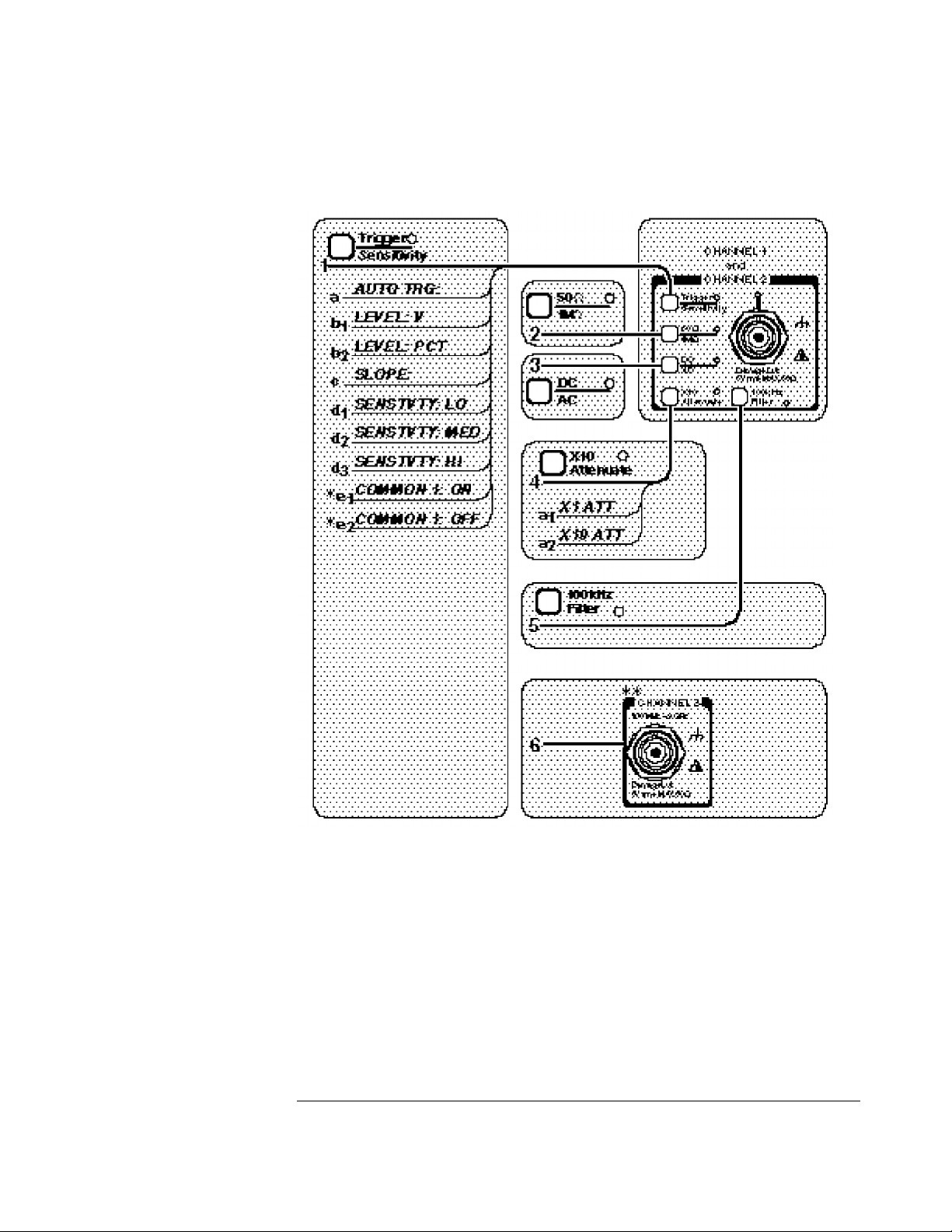
Chapter 2 Command Summary
Front Panel to SCPI Command Maps
Input Channels Conditioning Keys to SCPI Command Map
_____________________________
*For TI 1 TO 2 (Time Interval measurements) only.
**Channel 3 is optional.
Figure 2-1. Input Channels Conditioning Keys to SCPI Command
Map (Part 1 of 2)
2-4 Programming Guide
Page 31

Chapter 2
Input Channels Conditioning Keys to SCPI Command Map
(Cont.)
1 a. [:SENSe]:EVENt[1|2]:LEVel[:ABSolute]:AUTO ON|OFF
b1. [:SENSe]:EVENt[1|2]:LEVel[:ABSolute] <numeric_value> [V]
b2. [:SENSe]:EVENt[1|2]:LEVel:RELative <numeric_value> [PCT]
c. [:SENSe]:EVENt[1|2]:SLOPe POSitive | NEGative
d1. [:SENSe]:EVENt[1|2]:HYSTeresis:RELative 100*
d2. [:SENSe]:EVENt[1|2]:HYSTeresis:RELative 50
d3. [:SENSe]:EVENt[1|2]:HYSTeresis:RELative 0 **
e1. [:SENSe]:EVENt2:FEED “[:]INPut[1]”
e2. [:SENSe]:EVENt2:FEED “[:]INPut2”
2 :INPut[1|2]:IMPedance <numeric_value> [OHM]
3 :INPut[1|2]:COUPling AC|DC
4 a
. :INPut[1|2]:ATTenuation 1
1
a2. :INPut[1|2]:ATTenuation 10
5 :INPut[1|2]:FILTer ON | OFF
6 :INPut3:COUPling?
:INPut3:IMPedance?
__________________________
*Note, in firmware revisions 3317, 3335 and 3402, use 0.
**
Note, in firmware revisions 3317, 3335 and 3402, use 100.
Figure 2-1. Input Channels Conditioning Keys to SCPI Command
Map (Part 2 of 2)
Programming Guide 2-5
Page 32
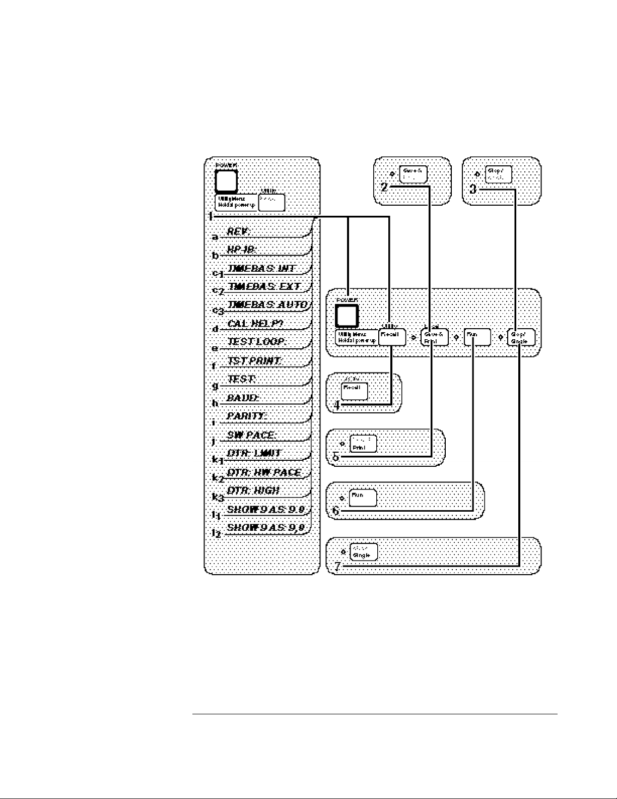
Chapter 2 Command Summary
Front Panel to SCPI Command Maps
Instrument Control, Utility, Recall, and Save & Print Keys to
SCPI Command Map
Figure 2-2. Instrument Control, Utility, Recall, and Save & Print
Keys to SCPI Command Map (Part 1 of 2)
2-6 Programming Guide
Page 33

Chapter 2
Instrument Control, Utility, Recall, and Save & Print Keys to
SCPI Command Map (Cont.)
1 a. *IDN?
b. No command
c1. [:SENSe]:ROSCillator:SOURce INTernal
c2. [:SENSe]:ROSCillator:SOURce EXTernal
c3. [:SENSe]:ROSCillator:SOURce:AUTO ON
d. No command (see Calibration menu, Figure 2-6)
e. No command
f. No command
g. *TST?
h. :SYSTem:COMMunicate:SERial:TRANsmit:BAUD <numeric_value>
I. :SYSTem:COMMunicate:SERial:TRANsmit:PARity[:TYPE]
EVEN | ODD | NONE
j. :SYSTem:COMMunicate:SERial:TRANsmit:PACE XON | NONE
k1. :SYSTem:COMMunicate:SERial:CONTrol:DTR LIMit
k2. :SYSTem:COMMunicate:SERial:CONTrol:DTR IBFull
k3. :SYSTem:COMMunicate:SERial:CONTrol:DTR ON
l1. :DISPlay[:WINDow]:TEXT:RADix DPOint
l2. :DISPlay[:WINDow]:TEXT:RADix COMMa
2 *SAV <Nrf>
3 :INITiate:CONTinuous OFF (if running)
OR
:ABORt (if singlemeasurement in progress)
4 *RCL <Nrf>
5 :HCOPy:CONTinuous ON | OFF
6 :INITiate:CONTinuous ON (if in single)
OR
:ABORt (if running)
7 :INITiate[:IMMediate]
Figure 2-2. Instrument Control, Utility, Recall, and Save & Print Keys
to SCPI Command Map (Part 2 of 2)
Programming Guide 2-7
Page 34
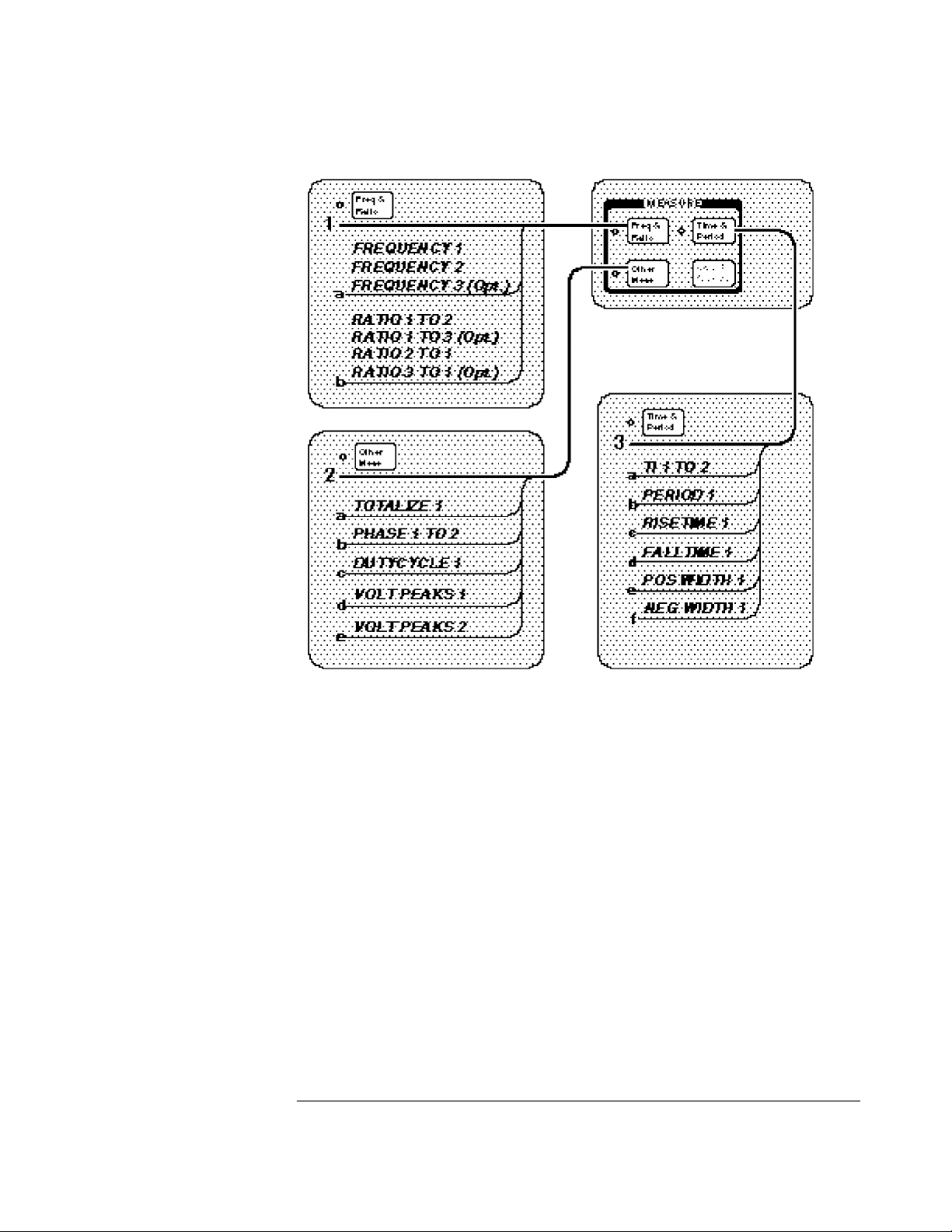
Chapter 2 Command Summary
Front Panel to SCPI Command Maps
MEASURE Keys to SCPI Command Map
Figure 2-3. MEASURE Keys to SCPI Command Map (Part 1 of 2)
2-8 Programming Guide
Page 35

Chapter 2
MEASURE Keys to SCPI Command Map (Cont.)
1 a. [:SENSe]:FUNCtion[:ON] “[:][XNONe:]FREQuency [1 | 2 | 3]”
b. [:SENSe]:FUNCtion[:ON] “[:][XNONe:]FREQuency:RATio
[1,2 |1,3 | 2,1 | 3,1]”
2 a. [:SENSe]:FUNCtion[:ON] “[:][XNONe:]TOTalize [1]”
b. [:SENSe]:FUNCtion[:ON] “[:][XNONe:]PHASe [1,2]”
c. [:SENSe]:FUNCtion[:ON] “[:][XNONe:]DCYCle [1]”
d. [:SENSe]:FUNCtion[:ON] “[:][XNONe:]VOLTage:MINimum [1]”
OR
[:SENSe]:FUNCtion[:ON] “[:][XNONe:]VOLTage:MAXimum [1]”
e. [:SENSe]:FUNCtion[:ON] “[:][XNONe:]VOLTage:MINimum 2”
OR
[:SENSe]:FUNCtion[:ON] “[:][XNONe:]VOLTage:MAXimum 2”
3 a. [:SENSe]:FUNCtion[:ON] “[:][XNONe:]TINTerval [1,2]”
b. [:SENSe]:FUNCtion[:ON] “[:][XNONe:]PERiod [1]”
c. [:SENSe]:FUNCtion[:ON] “[:][XNONe:]RISE:TIME [1]”
d. [:SENSe]:FUNCtion[:ON] “[:][XNONe:]FALL:TIME [1]”
e. [:SENSe]:FUNCtion[:ON] “[:][XNONe:]PWIDth [1]”
f. [:SENSe]:FUNCtion[:ON] “[:][XNONe:]NWIDth [1]”
Since the primary purpose of these front-panel keys is to change the function, the
corresponding [:SENSe]:FUNCtion[:ON] command is listed in the menu map
above. The front-panel keys, however, invoke couplings which affect other
settings, whereas the [:SENSe]:FUNCtion[:ON] command does not.
Figure 2-3. MEASURE Keys to SCPI Command Map (Part 2 of 2)
Programming Guide 2-9
Page 36
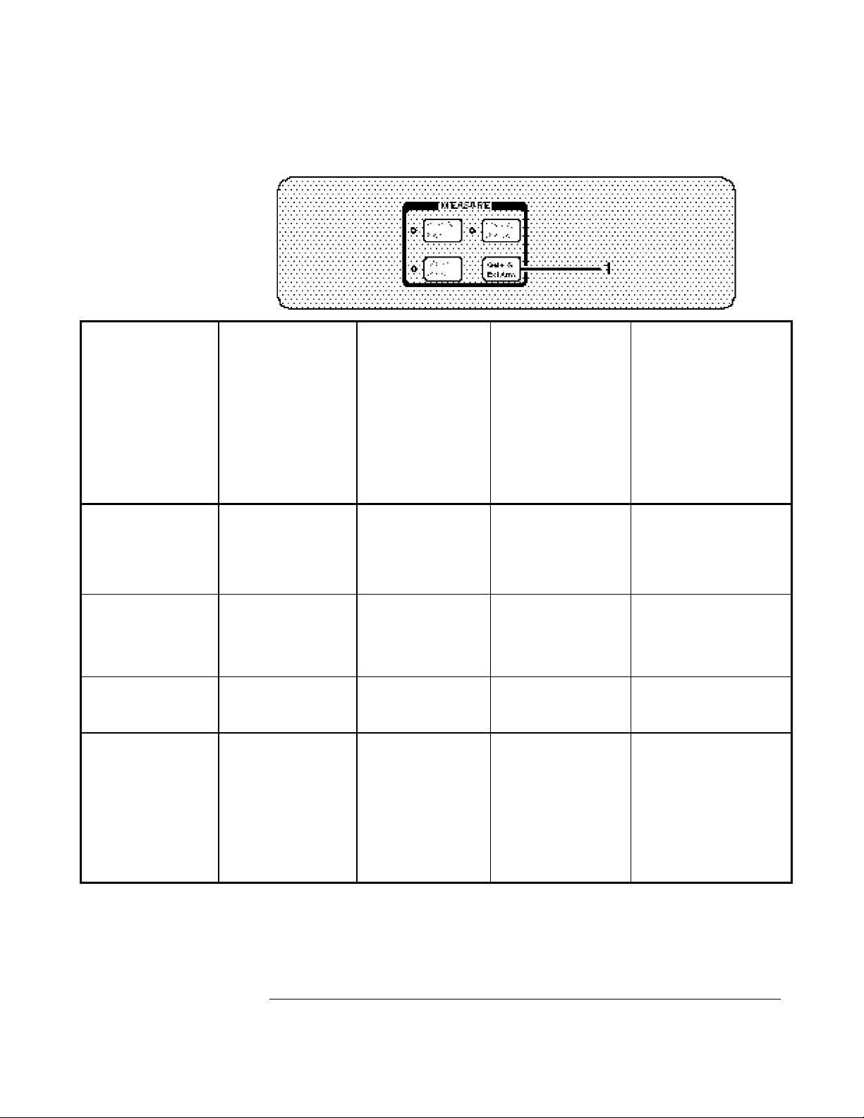
Chapter 2 Command Summary
Front Panel to SCPI Command Maps
Gate & ExtArm Key to SCPI Command Map
Freq, Period,
Ratio
(Agilent 53131A/132A)
Auto Arming:
a. GATE: AUTO
Digits Arming:
b. GATE:DIGITS
c. DIGITS: <digits>
Time Arming:
d. GATE:TIME
e. TIME: <time>
External Arming:
f. GATE: EXTERNL
g. START:POS
NEG
h1. STOP: AUTO
h2. STOP: NEG
POS
h3. STOP: TIME
I. TIME: <time>
Phase
Totalize
Rise Time, Fall
Time,+/-Width,
Time
Interval
Dutycycle
(Agilent 53131A/132A)
(Agilent 53131A/132A)
(Agilent 53131A/132A)
(Agilent 53131A and
Agilent 53132As with
S/N prefix below3646)
See page 2-14 for
Agilent 53132A (with
S/N prefix 3646 and
above).
Auto Arming:
a. ARM: AUTO
Auto Arming:
a.GATE: AUTO
Auto Arming:
a.ARM: AUTO
Auto Arming:
a. ARM: AUTO
b1. DELAY: NONE
b2. DELAY: TIME
c. TIME: <time>
_______________ _______________ _______________ _______________
Time Arming:
_______________
b. GATE:TIME
__________________ ________________
c. TIME: <time>
External Arming:
b. ARM: EXTERNL
c. SLOPE: POS
NEG
External Arming:
d. GATE:
EXTERNL
e. START:POS
NEG
f1. STOP: TIME
f2. STOP: NEG
POS
External Arming:
b. ARM: EXTERNL
c. SLOPE: POS
NEG
External Arming:
d. ARM: EXTERNL
e. SLOPE: POS
NEG
f1. DELAY: NONE
f2. DELAY: TIME
g. TIME: <time>
g. TIME: <time>
Figure 2-4. Gate & ExtArm Key to SCPI Command Map (Part 1 of 6)
2-10 Programming Guide
Page 37

Chapter 2
Gate & ExtArm Key to SCPI Command Map (Cont.)
1
Freq, Period, Ratio
Auto Arming:
a. [:SENSe]:FREQuency:ARM[:STARt]:SOURce IMMediate
[:SENSe]:FREQuency:ARM:STOP:SOURce IMMediate
Digits Arming:
b. [:SENSe]:FREQuency:ARM[:STARt]:SOURce IMMediate
[:SENSe]:FREQuency:ARM:STOP:SOURce DIGits
c. [:SENSe]:FREQuency:ARM:STOP:DIGits <numeric_value>
Time Arming:
d. [:SENSe]:FREQuency:ARM[:STARt]:SOURce IMMediate
[:SENSe]:FREQuency:ARM:STOP:SOURce TIMer
e. [:SENSe]:FREQuency:ARM:STOP:TIMer <numeric_value>
External Arming:
f. [:SENSe]:FREQuency:ARM[:STARt]:SOURce EXTernal
g. [:SENSe]:FREQuency:ARM[:STARt]:SLOPe POSitive | NEGative
h1. [:SENSe]:FREQuency:ARM:STOP:SOURce IMMediate
h2. [:SENSe]:FREQuency:ARM:STOP:SOURce EXTernal
[:SENSe]:FREQuency:ARM:STOP:SLOPe POSitive| NEGative
h3. [:SENSe]:FREQuency:ARM:STOP:SOURce TIMer
I. [:SENSe]:FREQuency:ARM:STOP:TIMer <numeric_value> [S]
Phase
Auto Arming:
a. [:SENSe]:PHASe:ARM[:STARt]:SOURce IMMediate
External Arming:
b. [:SENSe]:PHASe:ARM[:STARt]:SOURce EXTernal
c. [:SENSe]:PHASe:ARM[:STARt]:SLOPe POSitive | NEGative
Figure 2-4. Gate & ExtArm Key to SCPI Command Map (Part 2 of 6)
Programming Guide 2-11
Page 38

Chapter 2 Command Summary
Front Panel to SCPI Command Maps
Gate & ExtArm Key to SCPI Command Map (Cont.)
Totalize
Auto Arming:
a. [:SENSe]:TOTalize:ARM[:STARt]:SOURce IMMediate
[:SENSe]:TOTalize:ARM:STOP:SOURce IMMediate
Time Arming:
b1. [:SENSe]:TOTalize:ARM[:STARt]:SOURce IMMediate
b2. [:SENSe]:TOTalize:ARM:STOP:SOURce TIMer
c. [:SENSe]:TOTalize:ARM:STOP:TIMer <numeric_value> [S]
External Arming:
d. [:SENSe]:TOTalize:ARM[:STARt]:SOURce EXTernal
e. [:SENSe]:TOTalize:ARM[:STARt]:SLOPe POSitive | NEGative
f1. [:SENSe]:TOTalize:ARM:STOP:SOURce TIMer
f2. [:SENSe]:TOTalize:ARM:STOP:SOURce EXTernal
[:SENSe]:TOTalize:ARM:STOP:SLOPe POSitive | NEGative
g. [:SENSe]:TOTalize:ARM:STOP:TIMer <numeric_value> [S]
Rise Time, Fall Time, +/- Pulse Width, Dutycycle
Auto Arming:
a. [:SENSe]:TINTerval:ARM[:STARt]:SOURce IMMediate
External Arming:
b. [:SENSe]:TINTerval:ARM[:STARt]:SOURce EXTernal
c. [:SENSe]:TINTerval:ARM[:STARt]:SLOPe POSitive| NEGative
Figure 2-4. Gate & ExtArm Key to SCPI Command Map (Part 3 of 6)
2-12 Programming Guide
Page 39

Chapter 2
Gate & ExtArm Key to SCPI Command Map — For
Agilent 53131A (and Agilent 53132A With S/N Prefix Below
3646)
Time Interval (Agilent 53131A and Agilent 53132A With S/N Prefix Below
3646)
Auto Arming:
a. [:SENSe]:TINTerval:ARM[:STARt]:SOURce IMMediate
b1. [:SENSe]:TINTerval:ARM:STOP:SOURce IMMediate
b2. [:SENSe]:TINTerval:ARM:STOP:SOURce TIMer
c. [:SENSe]:TINTerval:ARM:STOP:TIMer <numeric_value> [S]
External Arming:
d. [:SENSe]:TINTerval:ARM[:STARt]:SOURce EXTernal
e. [:SENSe]:TINTerval:ARM[:START]:SLOPe POSitive | NEGative
f1. [:SENSe]:TINTerval:ARM:STOP:SOURce IMMediate
f2. [:SENSe]:TINTerval:ARM:STOP:SOURce TIMer
g. [:SENSe]:TINTerval:ARM:STOP:TIMer <numeric_value> [S]
Figure 2-4. Gate & ExtArm Key to SCPI Command Map (Part 4 of 6)
Programming Guide 2-13
Page 40

Chapter 2 Command Summary
Front Panel to SCPI Command Maps
Gate & ExtArm Key to SCPI Command Map (Cont.)— For
Agilent 53132A (With S/N Prefix 3646 and Above)
Time Interval (Agilent 53132A With S/N Prefix
3646 and Above)
Auto Arming:
a.
?
START: AUTO
b1. DELAY
b2. DELAY
b3. DELAY
c. T
d. E
External Arming:
e.
?
f.
g1.
g2.
g
3
h.
i.
j1. STOP
j2. STOP
k. SLOPE
m1. DELAY
m2. DELAY
m3. DELAY
n. T
o. E
?
: NONE
?
: TIME
?
: EVENT
?
: <time>
?
: <events>
START: EXT
?
SLOPE: POS
?
DELAY: NONE
?
DELAY: TIME
?
DELAY: EVENT
?
T: <time>
?
E: <events>
?
?
NEG
?
: AUTO
?
: EXT
?
: POS
?
: NONE
?
: TIME
?
: EVENT
: <time>
: <events>
NEG
Figure 2-4. Gate & ExtArm Key to SCPI Command Map (Part 5 of 6)
2-14 Programming Guide
Page 41

Chapter 2
Gate & ExtArm Key to SCPI Command Map (Cont.) — For
Agilent 53132A (With S/N Prefix 3646 and Above)
Time Interval (Agilent 53131A and Agilent 53132A With S/N Prefix Below
3646)
Auto Arming:
a. [:SENSe]:TINTerval:ARM:ESTART:LAYer2:SOURce IMMediate
[:SENSe]:TINTerval:ARM:ESTOP:LAYer2:SOURce IMMediate
b1. [:SENSe]:TINTerval:ARM:ESTOP[:LAYer[1]]:SOURce IMMediate
b2. [:SENSe]:TINTerval:ARM:ESTOP[:LAYer[1]]:SOURce TIMer
b3. [:SENSe]:TINTerval:ARM:ESTOP[:LAYer[1]]:SOURce INTernal2
c. [:SENSe]:TINTerval:ARM:ESTOP[:LAYer[1]]:TIMer <numeric_value> [S]
d. [:SENSe]:TINTerval:ARM:ESTOP[:LAYer[1]]:ECOunt <numeric_value>
External Arming:
e. [:SENSe]:TINTerval:ARM:ESTART:LAYer2:SOURce EXTernal
f. [:SENSe]:TINTerval:ARM:ESTART:LAYer2:SLOPe POSitive | NEGative
g1. [:SENSe]:TINTerval:ARM:ESTART[:LAYer[1]]:SOURce IMMediate
g2. [:SENSe]:TINTerval:ARM:ESTART[:LAYer[1]]:SOURce TIMer
g3. [:SENSe]:TINTerval:ARM:ESTART[:LAYer[1]]:SOURce INTernal1
h. [:SENSe]:TINTerval:ARM:ESTART[:LAYer[1]]:TIMer <numeric_value> [S]
i. [:SENSe]:TINTerval:ARM:ESTART[:LAYer[1]]:ECOunt <numeric_value>
j1. [:SENSe]:TINTerval:ARM:ESTOP:LAYer2:SOURce IMMediate
j2. [:SENSe]:TINTerval:ARM:ESTOP:LAYer2:SOURce EXTernal
k. [:SENSe]:TINTerval:ARM:ESTOP:LAYer2:SLOPe POSitive I NEGative
m1. [:SENSe]:TINTerval:ARM:ESTOP[:LAYer[1]]:SOURce IMMediate
m2. [:SENSe]:TINTerval:ARM:ESTOP[:LAYer[1]]:SOURce TIMer
m3. [:SENSe]:TINTerval:ARM:ESTOP[:LAYer[1]]:SOURce INTernal2
n. [:SENSe]:TINTerval:ARM:ESTOP[:LAYer[1]]:TIMer <numeric_value> [S]
o. [:SENSe]:TINTerval:ARM:ESTOP[:LAYer[1]]:ECOunt <numeric_value>
Figure 2-4. Gate & ExtArm Key to SCPI Command Map (Part 6 of 6)
Programming Guide 2-15
Page 42
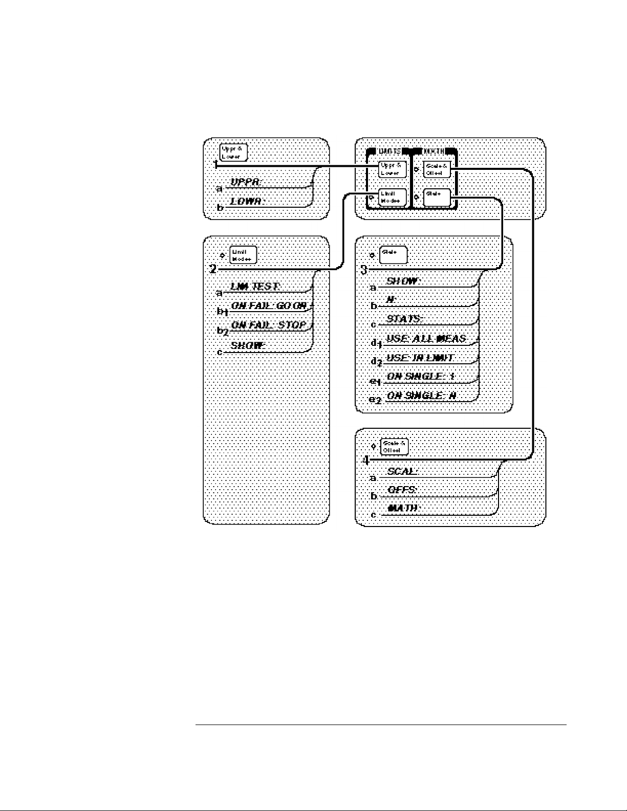
Chapter 2 Command Summary
Front Panel to SCPI Command Maps
LIMITS and MATH Keys to SCPI Command Map
Figure 2-5. LIMITS and MATH Keys to SCPI Command Map
(Part 1 of 2)
2-16 Programming Guide
Page 43

Chapter 2
LIMITS and MATH Keys to SCPI Command Map (Cont.)
1 a. :CALCulate2:LIMit:UPPer[:DATA] <numeric_value> [HZ | S | DEG]
b. :CALCulate2:LIMit:LOWer[:DATA] <numeric_value> [HZ | S | DEG]
2 a. :CALCulate2:LIMit:STATe OFF | ON
b1. :INITiate:AUTO OFF
b2. :INITiate:AUTO ON
c. :CALCulate2:LIMit:DISPlay GRAPh | NUMBer
3 a. :DISPlay[:WINDow]:TEXT:FEED “CALC3” *
:CALCulate3:AVERage:TYPE MAXimum | MINimum |
SDEViation | MEAN *
OR
:DISPlay[:WINDow]:TEXT:FEED “CALC2” *
b. :CALCulate3:AVERage:COUNt <numeric_value>
c. :CALCulate3:AVERage[:STATe] OFF | ON
d1. :CALCulate3:LFILter:STATe OFF
d2. :CALCulate3:LFILter:STATe ON
e1. :TRIGger:COUNt:AUTO OFF
e2. :TRIGger:COUNt:AUTO ON
4 a. :TRACe[:DATA] SCALE, <numeric_value>
b. :TRACe[:DATA] OFFSET, <numeric_value> [HZ | S | DEG]
c. :CALCulate:MATH:STATe OFF | ON
*Use CALC3:AVER:TYPE and :DISP[:WIND]:TEXT:FEED “CALC3” to specify
SHOW: STD DEV, MEAN, MAX, or MIN. Use DISP[:WIND]:TEXT:FEED “CALC2” to
specify SHOW: MEAS.
Figure 2-5. LIMITS and MATH Keys to SCPI Command Map
(Part 2 of 2)
Programming Guide 2-17
Page 44
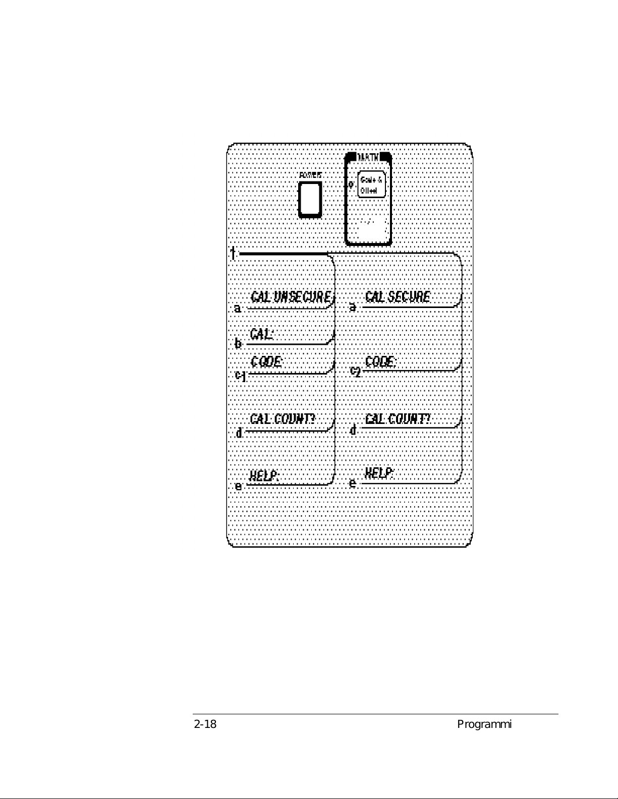
Chapter 2 Command Summary
Front Panel to SCPI Command Maps
Calibration Menu to SCPI Command Map
Figure 2-6. Calibration Menu to SCPI Command Map (Part 1 of 2)
2-18 Programming Guide
Page 45

Chapter 2
Calibration Menu to SCPI Command Map (Cont.)
1 a. :CALibration:SECurity:STATe?
b. :DIAGnostic:CALibration:INPut1:OFFSet:AUTO ONCE
:DIAGnostic:CALibration:INPut2:OFFSet:AUTO ONCE
:DIAGnostic:CALibration:INPut1:GAIN:AUTO ONCE
:DIAGnostic:CALibration:INPut2:GAIN:AUTO ONCE
:DIAGnostic:CALibration:TINTerval:QUICk
:DIAGnostic:CALibration:TINTerval:FINE[1 | 2 | 3 | 4]
:DIAGnostic:CALibration:ROSCillator:AUTO ONCE
c1. :CALibration:SECurity:CODE <new_code>
OR
:CALibration:SECurity:STATe ON, <present_code>
c2. :CALibration:SECurity:STATe OFF, <present_code>
d. :CALibration:COUNt?
e. No command
The Calibration Menu is accessed by holding the Scale & Offset key and
cycling POWERkey.
Figure 2-6. Calibration Menu to SCPI Command Map (Part 2 of 2)
Programming Guide 2-19
Page 46

Chapter 2 Command Summary
Agilent 53131A/132A Command Summary
Agilent 53131A/132A Command Summary
This section summarizes both the IEEE 488.2 Common and
Agilent 53131A/132A Standard Commands for Programmable Instruments
(SCPI) commands in tabular format. IEEE 488.2 Common commands are listed
first, followed by SCPI commands.
SCPI Conformance Information
The SCPI commands used in the Agilent 53131A/132A are in conformance with
the SCPI Standard Version 1992.0. The SCPI command set consists of the
following:
● Common commands as defined in IEEE 488.2-1987—listed and summarized
in Table 2-1.
● SCPI Subsystem commands as confirmed (and listed) in the SCPI Standard—
the commands defined in Table 2-2 as “Std.”
● SCPI Subsystem commands designed for the instrument in conformance with
SCPI standards but not yet listed in the SCPI Standard—the commands defined
in Table 2-2 as “New.”
Details of all Agilent 53131A/132A commands can be found in Chapter 4,
“Command Reference” of this programming guide.
Information on the SCPI commands format, syntax, parameter, and response
types is provided in Chapter 3, “Programming Your Universal Counter for
Remote Operation,” of this programming guide.
2-20 Programming Guide
Page 47

Chapter 2
IEEE 488.2 Common Commands
The Common Commands are general purpose commands that are common to all
instruments (as defined in IEEE 488.2). Common Commands are easy to
recognize because they all begin with an “*” (for example, *RST, *IDN?,
*OPC). These commands are generally not related to measurement
configuration. They are used for functions like resetting the instrument,
identification, or synchronization.
Table 2-1 lists the Common Commands in alphabetical order by mnemonic,
name and function. More information concerning the operation of IEEE 488.2
status reporting commands and structure can be found in the “Status Reporting”
section of Chapter 3. Standard explanations of the IEEE 488.2 Common
commands can be found in the ANSI/IEEE Std. 488.2-1987, IEEE Standard
Codes, Formats, Protocols, and Common Commands document.
Programming Guide 2-21
Page 48

Chapter 2 Command Summary
Agilent 53131A/132ACommand Summary
Table 2-1. IEEE 488.2 Common Commands
Mnemonic Command Name Function
*CAL?
*CLS
*DDT <arbitrary block>
*DMC <string>,
<arbitrary block>
*EMC <NRf>
*EMC?
*ESE <NRf>
*ESE?
Calibration
Clear Status
Define Device Trigger Command
Define Macro Command
Enable Macro Command
Enable Macro Query
Standard Event Status Enable
Standard Event Status Enable
Query
Causes the Counter to perform an internal interpolator selfcalibration and returns a response that indicates whether or
not the instrument completed the self-calibration without
error.
Clears Status data structures (Event Registers and Error
Queue).
Defines either INIT, FETC?, READ?, or nothing to be
executed when the Counter receives a GET or *TRG
command.
Assigns a sequence of zero or more commands/queries to a
macro label.
No query form.
Enables and disables expansion of macros.
Non-zero value enables; zero value disables.
Queries whether macros are enabled.
Sets the Standard Event Status Enable Register.
Queries the Standard Event Status Enable Register.
*ESR?
*GMC? <string>
*IDN?
*LMC?
*OPC
*OPC?
Note: Pending operations include measurements in progress.
Event Status Register Query
Get Macro Contents Query
Identification Query
Learn Macro Query
Operation Complete
Operation Complete Query
2-22 Programming Guide
Queries the Standard Event Status Register.
Queries the current definition of a currentlydefined macro
label.
Queries the Counter identification.
Queries the currently defined macro labels.
Causes Counter to set the operation complete bit in the
Standard Event Status Register when all pending operations
(see Note) are finished.
Places an ASCII “1” in the Output Queue when all pending
operations (see Note) are completed.
Page 49

Chapter 2
Table 2-1. IEEE 488.2 Common Commands (Continued)
Mnemonic Command Name Function
*OPT?
*PMC
*RCL <NRf>
*RST
*SAV <NRf>
*SRE <NRf>
*SRE?
*STB?
*TRG
Option Identification Query
Purge Macro Command
Recall
Reset
Save
Service Request Enable
Service Request Enable Query
Status Byte Query
Trigger
Identifies the options installed in the Counter.
Deletes all macros previously defined using the
*DMC command.
Restores the state of the Counter from a copy stored
in local non-volatile memory (0 through 20 are valid
memory registers).
Resets the Counter to a known state.
Stores the current state of the Counter in local nonvolatile memory (1 through 20 are valid memory
registers).
Set the Service Request Enable register.
Queries the Service Request Enable register.
Queries the Status Byte and Master Summary Status
bit.
This trigger command is the device-specific analog of
the IEEE 488.1 defined GET.
It initiates measurement, unless *DDT was used to
redefine device trigger.
*TST?
*WAI
Note: Pending operations include measurements in progress.
Self-Test Query
Wait-to-Continue
Programming Guide 2-23
Executes an internal self-test and reports the results.
Makes Counter wait until all pending operations (see
Note) are completed before executing commands
following *WAI command.
Page 50

Chapter 2 Command Summary
Agilent 53131A/132ACommand Summary
Agilent 53131A/132A SCPI Subsystem Commands
SCPI Subsystem commands include all measurement functions and some general
purpose functions. SCPI Subsystem Commands use a hierarchy relationship
between keywords that is indicated by a “:” (colon). For example, in the
SYST:ERR? query, the “:” between SYST and ERR? indicates ERR? is
subordinate to SYST.
Table 2-2 lists the SCPI Subsystem Commands in alphabetical order by the
command keyword. The table shows the Subsystem commands hierarchical
relationship, related parameters (if any), and any associated information and
comments.
Not all commands have a query form. Unless a command is specified as “No
Query” or “Query Only” in the “Comments” column of Table 2-2, it has both
a command and a query form. Any command in the table that is shown with a
“?” at the end,
is a “Query Only” command.
Std/New Column
The Std/New column in Table 2-2 gives the status of the command with respect
to the SCPI standard. The “Std” commands operate as defined in the SCPI
standard and as defined in this guide.
The category of “New” consists of commands that could be:
● SCPI approved but are not yet in the SCPI manual
● Agilent approved and submitted for SCPI approval.
● Not approved at all.
The “New” commands operate as defined in this guide.
Parameter Form Column
Refer to the section titled “Parameter Types” on page 3-11 in Chapter 3,
“Programming Your Universal Counter for Remote Operation,” for descriptions
of the different parameter types (such as <Boolean>, <NRf>, <arbitrary block>,
etc.).
2-24 Programming Guide
Page 51

Chapter 2
Table 2-2. Agilent 53131A/132A SCPI Command Summary
Keyword/Syntax Parameter Form Std/
New
:ABORt Std Event; no query. Aborts measurement in progress.
:CALCulate[1]
:DATA?
:FEED
:IMMediate
:AUTO
:MATH
[:EXPRession]
:CATalog?
[:DEFine]?
:NAME | :SELect
:STATe
:CALCulate2
:FEED
:IMMediate
:AUTO
:LIMit
:CLEar
:AUTO
[:IMMediate]
:DISPlay
:FAIL?
“[:]SENSe[1]”
<Boolean>
SCALE_OFFSET
<Boolean>
“[:]CALCulate[1]”
<Boolean>
<Boolean>
GRAPh | NUMBer
Std
Std
Std
Std
Std
Std
Std
New
New
New
Std
Std
Std
Std
Std
Std
Std
Std
Std
New
Std
Comments
Subsystem. Performs post-acquisition math processing
(scale and offset) and data transfer on the data
acquired by a SENSe function.
Query only. Returns scaled/offset measurement result.
Sets the data flow to be fed into the CALCulate block.
Event or query; causes the Counter to recalculate
existing data without re-acquiring.
Enables/disables automatic post-processing.
Subtree.
Subtree.
Returns the name of the defined equation,
SCALE_OFFSET.
Returns the expression (equation) used for
math (scale/offset) processing.
Sets the name of selected math expression (equation).
Enables/disables math (scale/offset) processing.
Note that this setting must be enabled for any of the
other :CALC[1] settings to be used.
Subsystem. Performs post-acquisition LIMit testing and
data transfer.
Sets the data flow to be fed into the CALCulate2 block.
Event; no query. Causes the Counter to recalculate
existing data without re-acquiring.
Enables/disables automatic post-processing.
Subtree. Collects together the commands associated
with controlling and getting reports from a single LIMit
test.
Subtree.
Enables the automatic clearing of limit test results.
Event; no query. Clears the limit test results.
Sets whether the measurement display is numeric or
symbolic (on a graph).
Query only. Returns a 0 or 1 to indicate if the last tested
measurement passed or failed the limit test.
0 = pass; 1 = fail.
Programming Guide 2-25
Page 52

Chapter 2 Command Summary
Agilent 53131A/132ACommand Summary
Table 2-2. Agilent 53131A/132A SCPI Command Summary (Continued)
Keyword/Syntax Parameter Form Std/
New
:CALCulate2 (Cont.)
:LIMit (Cont.)
:FCOunt
:LOWer?
:UPPer?
[:TOTal]?
:LOWer
[:DATA]
:STATe
:UPPer
[:DATA]
:PCOunt
[:TOTal]?
:CALCulate3
:AVERage
:ALL?
:CLEar
:COUNt
:CURRent?
[:STATe]
:TYPE
:DATA?
:FEED
<numeric_value> [HZ | S |
DEG]
<Boolean>
<numeric_value> [HZ | S |
DEG]
<numeric_value>
<Boolean>
MAXimum | MINimum |
SDEViation | SCALar or
MEAN
“[:]CALCulate[1]”
Std
New
New
New
Std
Std
Std
Std
Std
New
New
Std
Std
New
Std
Std
New
Std
Std
Std
Std
Comments
Subtree. An abbreviation for Fail COunt.
Query only. Returns the number of limit test
failures at the lower limit.
Query only. Returns the number of limit test
failures at the upper limit.
Query only. Returns the total number of
measurements that failed the limit test.
Subtree.
Sets lower limit used in limit testing.
Sets the limit test enable. Note that this setting
must be enabled for any of the other :CALC2
settings can be used.
Subtree.
Sets upper limit used in limit testing.
Subtree. An abbreviation for Pass COunt.
Query only. Returns the total number of
measurements that passed the limit test.
Subsystem. Performs post-acquisition statistics
computation and data transfer.
Subtree. Collects together the commands
associated with the Statistics capabilities.
Returns all four Statistics results (i.e., mean,
standard deviation, maximum, and minimum).
Event; no query. Clears the statistics results
and statistics count.
Selects number of measurements to combine
for statistics.
Query only. Returns the current number of data
values collected, thus far.
Enables/disables statistics post-processing.
Note that this setting must be enabled for any of
the other :CALC3 settings to be used.
Selects which statistic will be in
:CALC3:DATA?,and on the front-panel display.
Query only. Returns statistic result specified by
:CALC3:AVER:TYPE.
Sets the data flow to be fed into the
CALCulate3 block.
2-26 Programming Guide
Page 53

Chapter 2
Table 2-2. Agilent 53131A/132A SCPI Command Summary (Continued)
Keyword/Syntax Parameter Form Std/
New
:CALCulate3 (Cont.)
:LFILter
:LOWer
[:DATA]
:STATe
:UPPer
[:DATA]
:PATH?
:CALibration
[:ALL]?
:COUNt?
:DATA
:SECurity
:CODE
:STATe
<numeric_value> [HZ | S |
DEG]
<Boolean>
<numeric_value> [HZ | S |
DEG]
<arbitrary block>
<NRf>
<Boolean>, <NRf>
New
New
New
New
New
New
Std
Std
Std
New
Std
New
New
New
Comments
Subtree. Limit FILter for statistics.
Subtree.
Sets the statistics filter lower limit.
Sets the statistics filter enable.
Subtree.
Sets the statistics filter upper limit.
Query only. Returns LFIL, AVER.
Subsystem.
Query only. Causes an internal interpolator
self-calibration.
Query only. Returns value indicating number
of times the Counter has been calibrated.
Transfers the calibration data (input gain, input
offset, reference oscillator, and time interval).
No query. Sets the calibration security code.
Enables or prevents calibration of the Counter.
Query returns security status. 0 = unsecure;
calibration allowed. 1 = secure; calibration
disallowed.
:CONFigure Std See Measurement Instructions in this table.
:DIAGnostic
:CALibration
:INPut[1|2]
:GAIN
:AUTO
:OFFSet
:AUTO
:INTerpolator
:AUTO
ONCE | OFF
ONCE | OFF
ONCE | OFF | ON
Std
New
New
New
New
New
New
New
New
Subsystem.
Subtree.
Subtree. 1 | 2 specifies channel.
Subtree.
ONCE calibrates input gain.
Subtree.
ONCE calibrates input offset.
Subtree.
ONCE calibrates the interpolators.
Programming Guide 2-27
Page 54

Chapter 2 Command Summary
Agilent 53131A/132ACommand Summary
Table 2-2. Agilent 53131A/132A SCPI Command Summary (Continued)
Keyword/Syntax Parameter Form Std/
New
:DIAGnostic (Cont.)
:CALibration (Cont.)
:ROSCillator
:AUTO
:STATus?
:TINTerval
:FINE
:QUICk
:DISPlay
:ENABle
:MENU
[:STATe]
[:WINDow]
:TEXT
:FEED
:RADix
ONCE | OFF
[1 | 2 | 3 | 4]
<Boolean>
OFF
“[:]CALCulate2” |
“[:]CALCulate3”
COMMa | DPOint
New
New
New
New
New
New
Std
Std
Std
Std
Std
Std
Std
New
Comments
Subtree. ROSCillator is an abbreviation for Reference
OSCillator.
ONCE calibrates the timebase. This command is
usable only if the instrument contains the medium or
high stabilityoscillator option.
Query only. Returns status of last calibration.
0 = pass; 1 = fail.
Subtree.
Event; no query. Four steps which calibrate out
Ch1, 2 electrical path length differences.
Event; no query. Calibrates out Ch1, 2 electrical path
length differences.
Subsystem. Controls the selection and presentation
of textual information on the display.
Controls whether the whole display is visible.
Subtree.
Sets the Counter to switch from the menu displayto
the result display.
Subtree.
Subtree. Allows for the display of textual information.
Sets which data flow is fed into the display. “CALC2”
specifies the raw measurement, scaled/offset
measurement, or Limit Graph display. “CALC3”
specifies the statistics result display.
Sets the character used to separate integral and
fractional portions of a number. (USA numerical
convention is Decimal POint.)
:FETCh
:FORMat
[:DATA]
:HCOPy
:CONTinuous
Std See Measurement Instructions in this table.
ASCii | REAL
<Boolean>
Std
Std
New
New Enables or disables printing results.
Subsystem. Sets a data format for transferring
numeric information.
Sets the data format.
2-28 Programming Guide
Page 55

Chapter 2
Table 2-2. Agilent 53131A/132A SCPI Command Summary (Continued)
Keyword/Syntax Parameter Form Std/
New
:INITiate
:AUTO
:CONTinuous
[:IMMediate]
:INPut[1|2]
:ATTenuation
:COUPling
:FILTer
[:LPASs]
[:STATe]
:FREQuency?
:IMPedance
:INPut3
:COUPling?
:IMPedance?
<Boolean>
<Boolean>
1 | 10
AC | DC
<Boolean>
<numeric_value> [OHM]
Std
New
Std
Std
Std
Std
Std
Std
Std
Std
Std
Std
Std
Std
Std
Comments
Subsystem. Controls the initiation of measurements.
AUTO ON enables the Counter to automatically stop
measuring on a limit test failure. AUTO OFF disables
the automatic stop.
Sets the enable for continuously initiated
measurements.
Event; no query. Causes the instrument to initiate the
number of measurements specified by
:TRIGger:COUNt:AUTO.
Subsystem. Controls the characteristics
of the instrument’s input ports. :INPut1= channel 1
and :INPut2= channel 2
Sets input attenuation.
Sets input coupling.
Subtree. Allows a low pass filter to be inserted in the
path of the measurement signal.
Subtree. Controls the Low PASs filter.
Sets the Low PASs filter enable.
Query only. Returns the cutoff frequency of the low
pass filter. Units are Hertz.
Sets input impedance (50 W or 1 MW).
Subsystem. Queries the characteristics of the
Counter’s input channel 3.
Query only. Returns channel 3 input coupling.
Query only. Returns channel 3 input impedance.
:MEASure
Std See Measurement Instructions in this table.
Programming Guide 2-29
Page 56

Chapter 2 Command Summary
Agilent 53131A/132ACommand Summary
Table 2-2. Agilent 53131A/132A SCPI Command Summary (Continued)
Keyword/Syntax Parameter Form Std/
New
Measurement Instructions*
:CONFigure[:SCALar]:<function>
:CONFigure?
:MEASure[:SCALar]:<function>?
:READ[[:SCALar]:<function>]?
:FETCh[[:SCALar]:<function>]?
See <parameters> and
<source_list> in table
on the next page.
See <parameters> and
<source_list> in table
on the next page.
Std
Std
Std
Std
Std
Comments
Configures instrument to perform
specified measurement.
Returns function configured bythe last
:CONF or :MEAS command.
Configures instrument, initiates
measurement, and queries for the result (i.e.,
provides complete measurement sequence).
Initiates measurement, and queries for the
result. (Performs a :FETCh? on “fresh” data.)
Queries the result.
*The <function> and corresponding <parameters> and <source list> are defined by the following listing in this table
(see next page).
2-30 Programming Guide
Page 57

Chapter 2
Table 2-2. Agilent 53131A/132A SCPI Command Summary (Continued)
<function> *
[:VOLTage]:DCYCle
<parameters>
[<reference>]
[,<source_list>] **
[ (@1) ]
or
[:VOLTage]:PDUTycycle
[:VOLTage]:FALL:TIME
[<reference>]
[<lower_reference>[,upper_reference>]]
[ (@1) ]
[ (@1) ]
or
[:VOLTage]:FTIMe
[:VOLTage]:FREQuency
[:VOLTage]:FREQuency:RATio***
[<lower_reference>[,upper_reference>]]
[<expected_value>[,<resolution>]]
[<expected_value>[,<resolution>]]
[ (@1) ]
[ (@1) | (@2) | (@3) ]
[ (@1), (@2 | @3) |
(@2 | @3), (@1) ]
[:VOLTage]:MAXimum [ (@1) | (@2) ]
[:VOLTage]:MINimum [ (@1) | (@2) ]
[:VOLTage]:NWIDth [<reference>] [ (@1) ]
[:VOLTage]:PERiod [<expected_value>[,<resolution>]] [ (@1) | (@2) | (@3) ]
[:VOLTage]:PHASe [ (@1), (@2) ]
[:VOLTage]:PTPeak [ (@1) | (@2) ]
[:VOLTage]:PWIDth [<reference>] [ (@1) ]
Std/
New
Std
Std
Std
Std
Std
New
Std
Std
Std
Std
Std
Std
Std
[:VOLTage]:RISE:TIME
[<lower_reference>[,upper_reference>]] [ (@1) ]
or
[:VOLTage]:RTIMe [<lower_reference>[,upper_reference>]] [ (@1) ]
[:VOLTage]:TINTerval [ (@1), (@2) ]
[:VOLTage]:TOTalize:CONTinuous****
[ (@1) ]
[:VOLTage]:TOTalize:TIMed [<gate_time>] [ (@1) ]
______________________________
*The only functions which can be derived (using FETC? or READ?) from the stored data are
period to/from frequency, maximum to/from minimum, maximum to/from peak-to-peak, and
minimum to/from peak-to-peak. All other functions require an acquisition of a new type.
**<source_list> has the same syntax as SCPI <channel _list> syntax. For example, a
single-channel function (e.g., frequency, period, etc.) woulduse (@1) to specify channel 1,
whereas a two-channel function (e.g., time interval, phase, and frequencyratio) would use
(@1), (@2) to specify a measurement between channel 1 and channel 2.
***For Agilent 53131A firmware revisions below 3335, only Ratio 1 to 2 and Ratio 1 to 3 were
offered.
****This <function> is only allowed with :CONFigure.
Programming Guide 2-31
Std
Std
New
New
New
Page 58

Chapter 2 Command Summary
Agilent 53131A/132ACommand Summary
Table 2-2. Agilent 53131A/132A SCPI Command Summary (Continued)
Keyword/Syntax Parameter Form Std/
Comments
New
:MEMory
Std
Subsystem. Manages instrument
memory.
:DELete
:MACRo
<string>
Std
New
Subtree.
Event; no query. Deletes the macro with
the name specified bythe string
parameter.
:FREE
:MACRo?
Std
Std
Subtree.
Query only. Returns memory usage and
availabilitycorresponding to macro data.
:NSTates?
Std
Query only. Returns the number of
available *SAV/*RCL states in the
instrument.
:READ Std See Measurement Instructions in this
table.
[:SENSe]
:DATA?
[“[:]SENSe[1]”]
Std
Std
Subsystem setup commands.
Query only. Returns the current
measurement result data of the SENSe
subsystem (no scale or offset applied).
:EVENt[1|2]
:HYSTeresis
:RELative
<numeric_value> [PCT]
New
New
New
Subtree. Defines the “trigger event.”
Subtree.
1
Sets the size of the hysteresis window
as a percentage of allowable hysteresis.
2
Sets the sensitivityof the input channel
as a percentage of allowable sensitivity.
:LEVel
[:ABSolute]
<numeric_value> [V]
New
New
Subtree.
Sets the level at the center of the
hysteresis window.
:AUTO
:RELative
<Boolean>
<numeric_value> [PCT]
New
New
Sets the “auto-trigger” enable.
Sets the percentage of the peak-to-peak
range of the signal at which the
instrument will auto trigger. 0-100%.
:SLOPe
POSitive | NEGative
New
Sets which edge of the input signal will
be considered an event.
:EVENt2
:FEED
“[:]INPut[1] | [:]INPut2”
New
New
Subtree.
Sets the common/separate enable.
INPut2 is separate; INPut1 is common.
(Only applies for Time Interval function.)
______________________________
1
Current firmware revision.
2
Prior firmware revisions 3317, 3335, and 3402.
2-32 Programming Guide
Page 59

Chapter 2
Table 2-2. Agilent 53131A/132A SCPI Command Summary (Continued)
Keyword/Syntax Parameter Form Std/
New
[:SENSe] (Cont.)
:EVENt3
:LEVel
[:ABSolute]?
:SLOPe?
:FREQuency
:ARM
[:STARt]
:SLOPe
:SOURce
:STOP
:DIGits
:SLOPe
:SOURce
:TIMer
:EXPected[1|2|3]
:AUTO
POSitive | NEGative
IMMediate |EXTernal
<numeric_value>
POSitive | NEGative
IMMediate | EXTernal |
TIMer | DIGits
<numeric_value> [S]
<numeric_value> [HZ]
ON
New
New
New
New
Std
New
New
New
New
New
New
New
New
New
New
New
Comments
Subtree. Queries the characteristics of the “trigger
event” for channel 3 input.
Subtree.
Query only. Returns the channel 3 input trigger level.
Query only. Returns the edge of the channel 3 input
that will be considered an event.
Subtree. Controls the frequency, frequency ratio, and
period measuring capabilities of the instrument.
Subtree. Synchronizes the frequency start and stop
arm with events.
Subtree.
Sets the slope of the external start arm signal used in
external arming frequency, frequency ratio, and
period measurements. Only applies when
[:SENS]:FREQ:ARM[:STAR]:SOUR EXT is selected.
Sets the start arm for frequency, frequency ratio, and
period measurements.
Subtree.
Sets the resolution in terms of digits used in arming
frequency, frequency ratio, and period
measurements. Only applies when
[:SENS]:FREQ:ARM:STOP:SOUR DIG is selected.
Sets the slope of the external stop arm signal used in
external arming frequency, frequency ratio, and
period measurements. Only applies when
[:SENS]:FREQ:ARM:STOP:SOUR EXT is selected.
Sets the stop arm for frequency, frequency ratio, and
period measurements.
Sets the gate time used in arming frequency,
frequency ratio, and period measurements. Only
applies when [:SENS]:FREQ:ARM:STOP:SOUR TIM
is selected.
Specifies the approximate frequency of a signal you
expect to measure at channel 1, 2, or 3.
Configures Counter to perform a pre-measurement
step to automaticallydetermine the approximate
frequency of the measurement signal(s).
Programming Guide 2-33
Page 60

Chapter 2 Command Summary
Agilent 53131A/132ACommand Summary
Table 2-2. Agilent 53131A/132A SCPI Command Summary (Continued)
Keyword/Syntax Parameter Form Std/
New
[:SENSe] (Cont.)
:FUNCtion
[:ON]
:PHASe
:ARM
[:STARt]
:SLOPe
:SOURce
:ROSCillator
:EXTernal
:CHECk
:FREQuency?
<sensor_function> (See below)
“[:][XNONe:]DCYCle [1]”
“[:][XNONe:]PDUTycycle [1]”
“[:][XNONe:]FALL:TIME [1]”
“[:][XNONe:]FTIMe [1]”
“[:][XNONe:]FREQuency [1 | 2 | 3]”
“[:][XNONe:]FREQuency:RATio
[1,2 | 1,3 | 2,1 | 3,1]”
“[:][XNONe:]NWIDth [1]”
“[:][XNONe:]PERiod [1 | 2 |3]”
“[:][XNONe:]PHASe [1,2]”
“[:][XNONe:]PWIDth [1]”
“[:][XNONe:]RISE:TIME [1]”
“[:][XNONe:]RTIMe [1]”
“[:][XNONe:]TINTerval [1,2]”
“[:][XNONe:]TOTalize [1]”
“[:][XNONe:]VOLTage:MAXimum [1 | 2]”
“[:][XNONe:]VOLTage:MINimum [1 | 2]”
“[:]{XNONe:]VOLTage:PTPeak [1 | 2]
POSitive | NEGative
IMMediate | EXTernal
ON | OFF | ONCE
Std
Std
New
New
New
New
Std
Std
New
Std
Std
New
New
New
New
Std
Std
New
New
New
New
New
New
New
Std
Std
New
Std
Comments
Subtree. Selects the <sensor function> to
be sensed bythe instrument.
Sets the <sensor function> to be sensed by
the instrument.
(Positive) duty cycle on channel 1.
(Positive) duty cycle on channel 1.
Fall Time on channel 1.
Fall Time on channel 1.
Frequency on channel 1, 2, or 3.
1
FrequencyRatio 1 to 2, 1 to 3, 2 to 1, or 3
to 1.
Negative Pulse Width on channel 1.
Period on channel 1, 2, or 3.
Phase of channel 1 relative to channel 2.
Positive Pulse Width on channel 1.
Rise Time on channel 1.
Rise Time on channel 1.
Time Interval channel 1 to channel 2.
Totalize on channel 1.
Voltage Maximum on channel 1 or 2.
Voltage Minimum on channel 1 or 2.
Voltage Peak to Peak on Channel 1 or 2.
Subtree. Controls the phase measuring
capabilities of the instrument.
Subtree.
Subtree. Synchronizes Phase start arm with
events.
Sets the slope of the external start arm
signal used in external arming phase
measurements. Only applies when
[:SENS]:PHAS:ARM[:STAR]:SOUR EXT is
selected.
Sets the start arm for phase measurements.
Subtree. Controls the Reference OSCillator.
Subtree.
Set the enable for checking the validity and
presence of the external reference.
Query only. Returns the frequency value of
the external reference oscillator.
______________________________
1
For Agilent 53131A firmware revisions below 3335, only Ratio 1 to 2 and Ratio 1 to 3 wereoffered.
2-34 Programming Guide
Page 61

Chapter 2
Table 2-2. Agilent 53131A/132A SCPI Command Summary (Continued)
Keyword/Syntax Parameter Form Std/
New
[:SENSe] (Cont.)
:ROSCillator (Cont.)
:SOURce
:AUTO
:TINTerval
:ARM (Agilent
53131A and Agilent
53132A with S/N prefix
below 3646)
[:STARt]
:SLOPe
:SOURce
:STOP
:SOURce
:TIMer
:TOTalize
:ARM
[:STARt]
:SLOPe
:SOURce
INTernal | EXTernal
<Boolean>
See Table 2-2A on
page 2-38 for Agilent
53132A (with S/N 3646
and above) TINTerval
ARM commands)
POSitive | NEGative
IMMediate | EXTernal
IMMediate | TIMer
<numeric_value> [S]
POSitive | NEGative
EXTernal | IMMediate
Std
Std
New
New
New
New
New
New
New
New
New
New
New
New
New
Comments
Sets the selection of a reference timebase.
Sets the enable for automatically selecting a reference
timebase.
Subtree. Controls the time interval (including Time
Interval, Rise Time, Fall Time, Dutycycle, and Pulse
Width functions) measuring capabilities of the instrument.
Subtree. Synchronizes the time interval start and stop
arm with events.
Subtree.
Sets the slope of the external start arm signal used in
external arming time interval measurements (including
Time Interval, Rise Time, Fall Time, Dutycycle, and Pulse
Width functions). Only applies when
[:SENS]:TINT:ARM[:STAR]:SOUR EXT is selected.
Sets the start arm for time interval (including Time
Interval, Rise Time, Fall Time, Dutycycle, and Pulse
Width) measurements.
Subtree.
Sets the stop arm (i.e., the delay) for Time Interval
measurements.
Sets the time used to delay the stop arm for Time Interval
measurements. Only applies when
[:SENS]:TINT:ARM:STOP:SOUR TIM is selected.
Subtree. Controls the totalize measuring capabilities of
the instrument.
Subtree. Synchronizes totalize start and stop arm with
events.
Subtree.
Sets the slope of the external start arm signal used in
external arming totalize measurements. Only applies
when [:SENS]:TOT:ARM[:STAR]:SOUR EXT is selected.
Sets the start arm for totalize measurements.
Programming Guide 2-35
Page 62

Chapter 2 Command Summary
Agilent 53131A/132ACommand Summary
Table 2-2. Agilent 53131A/132A SCPI Command Summary (Continued)
Keyword/Syntax Parameter Form Std/
New
[:SENSe] (Cont.)
:TOTalize (Cont.)
:ARM (Cont.)
:STOP
:SLOPe
:SOURce
:TIMer
:STATus
:OPERation
:CONDition?
:ENABle
[:EVENt]?
:NTRansition
:PTRansition
:PRESet
:QUEStionable
:CONDition?
:ENABle
[:EVENt]?
:NTRansition
:PTRansition
POSitive | NEGative
EXTernal | TIMer | IMMediate
<numeric_value> [S]
<non-decimal numeric> |
<NRf>
<non-decimal numeric> |
<Nrf>
<non-decimal numeric> |
<NRf>
<non-decimal numeric> |
<NRf>
<non-decimal numeric> |
<NRf>
<non-decimal numeric> |
<NRf>
New
New
New
New
Std
Std
Std
Std
Std
Std
Std
Std
Std
Std
Std
Std
Std
Std
Comments
Subtree.
Sets the slope of the external stop arm signal used
in external arming totalize measurements. Only
applies when [:SENS]:TOT:ARM:STOP:SOUR EXT
is selected.
Sets the stop arm for totalize measurements.
Sets the gate time used in totalize measurements.
Only applies when
[:SENS]:TOT:ARM:STOP:SOUR TIM is selected.
Subsystem. Controls the SCPI-defined (Operation
and Questionable) status-reporting structures.
Subtree.
Query only. Queries the Operation Condition Status
Register.
Sets the Operation Event Status Enable Register.
Query only. Queries the Operation Event Status
Register.
Sets the negative transition filter for the Operation
status reporting structure.
Sets the positive transition filter for the Operation
status reporting structure.
Event; No query. Presets the enable registers and
transition filters associated with the Operation and
Questionable status reporting structures.
Subtree.
Query only. Queries the Questionable Data
Condition StatusRegister.
Sets the Questionable Data Event Status Enable
Register.
Query only. Queries the Questionable Data Event
Status Register.
Sets the positive transition filter for the
Questionable Data status reporting structure.
Sets the negative transition filter for the
Questionable Data status reporting structure.
2-36 Programming Guide
Page 63

Chapter 2
Table 2-2. Agilent 53131A/132A SCPI Command Summary (Continued)
Keyword/Syntax Parameter Form Std/
New
:SYSTem
:COMMunicate
:SERial
:CONTrol Std Subtree.
:DTR IBFull | ON | LIMit Std Sets the usage of the DTR line of the RS-232
:TRANsmit Std Subtree. Affects parameters associated with
:BAUD <numeric_value> Std Sets the baud rate.
:PACE XON | NONE Std Sets the software pacing scheme.
:PARity Std Subtree. Controls the parity of the channel.
[:TYPE] EVEN | ODD | NONE Std Sets the parity scheme.
:ERRor? Std Query only. Queries the oldest error in the Error
:KEY <numeric_value> Std Simulates the pressing of a front-panel key.
Std
Std
Std
Comments
Subsystem. Collects the functions that are not
related to instrument performance.
Subtree. Collects together configuration of
control/communication interfaces.
Subtree. Controls the physical configuration of
the RS- 232C port.
port.
transmission.
Queue and removes the error from the queue
(first in, first out).
:LOG? New Query only. Returns a comma-separated list of
integers representing all of the entries in the
Key Queue.
:VERSion? Std Query only. Returns the SCPI version number
with which the Counter complies.
:TRACe
:CATalog?
[:DATA]
[:DATA]
[:DATA]?
[:DATA]?
:TRIGger
:COUNt
:AUTO
OFFSET, <numeric_value> [HZ
| S | DEG]
SCALE, <numeric_value>
OFFSET
SCALE
<Boolean>
Std
Std
Std
Std
Std
Std
Std
Std
New
Subsystem.
Query only. Returns list of intrinsic constants.
Sets the offset value.
Sets the scale value.
Queries the offset value.
Queries the scale value.
Subsystem.
Subtree.
Controls the number of measurements to be
made when :INIT[:IMM] is performed.
Programming Guide 2-37
Page 64

Chapter 2 Command Summary
Agilent 53131A/132ACommand Summary
Table 2-2A. Agilent 53132A (S/N Prefix 3646 and Above) Time Interval
Arming SCPI Command Summary
Keyword/Syntax Parameter Form Std/
New
[:SENSe] (Cont.)
:TINTerval
:ARM
:ESTART
:LAYer2
:SLOPe
:SOURce
[:LAYer[1]]
:ECOunt
:SOURce
:TIMer
:ESTOP
:LAYer2
:SLOPe
:SOURce
[:LAYer[1]]
:ECOunt
POSitive | NEGative
IMMediate | EXTernal
<numeric_value>
IMMediate | TIMer |
INTernal1
<numeric_value>
POSitive | NEGative
IMMediate | EXTernal
<numeric_value>
New
New
New
New
New
New
New
New
New
New
New
New
New
New
New
New
Comments
Subtree. Controls the time interval (including
Time Interval, Rise Time, Fall Time, Dutycycle,
and Pulse Width functions) measuring
capabilities of the instrument.
Subtree. Synchronizes the time interval start and
stop arm with events.
Sets the slope of the external start arm signal
used in external arming Time Interval
measurements (including Time Interval, Rise
Time, Fall Time, Dutycycle, and Pulse Width).
Sets the start arm for time interval (including
Time Interval, Rise Time, Fall Time, Dutycycle,
and Pulse Width) measurements.
Sets the event count used to delay the start arm
for Time Interval measurements. Only applies
when [:SENS]:TINT:ARM:ESTART:SOUR INT1
is selected.
Sets the start arm delay for Time Interval
measurements.
Sets the time used to delay the start arm for
Time Interval measurements. Only applies when
[:SENS]:TINT:ARM:ESTART:SOUR TIM is
selected.
Sets the slope of the external stop arm signal
used in external arming Time Interval
measurements.
Sets the stop arm for Time Interval
measurements.
Sets the event count used to delay the stop arm
for Time Interval measurements. Only applies
when [:SENS]:TINT:ARM:ESTOP:SOUR INT2 is
selected.
2-38 Programming Guide
Page 65

Chapter 2
Table 2-2A. Agilent 53132A (S/N Prefix 3646 and Above) Time Interval
Arming SCPI Command Summary (Continued)
Keyword/Syntax Parameter Form Std/
New
[:SENSe] (Cont.)
:TINTerval (Cont.)
:ARM (Cont.)
:ESTOP (Cont.)
[:LAYer[1]]
:SOURce
:TIMer
[:STARt]
:SLOPe
:SOURce
:STOP
:SOURce
:TIMer
IMMediate | TIMer |
INTernal2
<numeric_value>
POSitive | NEGative
IMMediate | EXTernal
IMMediate | TIMer
<numeric_value>
New
New
New
New
New
New
New
New
Comments
Sets the stop arm delay for Time Interval
measurements.
Sets the time used to delay the stop arm for
Time Interval measurements. Only applies
when [:SENS]:TINT:ARM:ESTOP:SOUR TIM is
selected.
Sets the slope of the external start arm signal
used in external arming Tme Interval
measurements (including Time Interval, Rise
Time, Fall Time, Dutycycle, and Pulse Width).
Only applies when
[:SENS]:TINT:ARM[:STAR]:SOUR EXT is
selected.
Sets the start arm for time interval (including
Time Interval, Rise Time, Fall Time, Dutycycle,
and Pulse Width) measurements.
Subtree.
Sets the stop arm (i.e., the delay) for Time
Interval measurements.
Sets the time used to delay the stop arm for
Time Interval measurements. Only applies
when [:SENS]:TINT:ARM:STOP:SOUR TIM is
selected.
Programming Guide 2-39
Page 66

Chapter 2 Command Summary
*RST Response
*RST Response
The IEEE 488.2 *RST command returns the instrument to a specified state
optimized for remote operation. (Use *CLS to clear the status event registers and
the SCPI error queue.)
The states of commands affected by the *RST command are described in Table
2-3. Since the Agilent 53131A and Agilent 53132A have different arming
capabilities for Time Interval measurements, sub-tables (Table 2-3A and
Table 2-3B) are provided. Table 2-3A describes the state of the
Agilent 53131A’s [:SENSe]:Interval commands affected by the *RST command,
and Table 2-3B describes the Agilent 531312A’s [:SENSe]:Interval commands
affected by the *RST command. Table 2-4 lists commands that are unaffected by
*RST.
Table 2-3. Agilent 53131A/132A*RST State
Command Header Parameter State
:CALCulate[1]:FEED
:CALCulate[1]:IMMediate:AUTO
:CALCulate[1]:MATH[:EXPRession]:NAME
:CALCulate[1]:MATH:STATe
:CALCulate2:FEED
:CALCulate2:IMMediate:AUTO
:CALCulate2:LIMit:CLEar:AUTO
:CALCulate2:LIMit:DISPlay
:CALCulate2:LIMit:LOWer[:DATA]
:CALCulate2:LIMit:STATe
:CALCulate2:LIMit:UPPer[:DATA]
:CALCulate3:AVERage:COUNt
:CALCulate3:AVERage[:STATe]
:CALCulate3:AVERage:TYPE
:CALCulate3:FEED
:CALCulate3:LFILter:LOWer[:DATA]
:CALCulate3:LFILter:STATe
:CALCulate3:LFILter:UPPer[:DATA]
DDT
*
:DIAGnostic:CALibration:INTerpolator:AUTO ON | OFF | ONCE ON
:DISPlay:ENABle
:DISPlay:MENU[:STATe]
:DISPlay[:WINDow]:TEXT:FEED
“[:]SENSe[1]”
<Boolean>
SCALE_OFFSET
<Boolean>
“[:]CALCulate[1]”
<Boolean>
<Boolean>
GRAPh | NUMBer
<numeric_value>
<Boolean>
<numeric_value>
<numeric_value>
<Boolean>
MAXimum | MINimum |
SDEViation | MEAN
“[:]CALCulate[1]”
<numeric_value>
<Boolean>
<numeric_value>
<arbitrary block> #14INIT
<Boolean>
OFF
“[:]CALCulate2” |
“[:]CALCulate3”
“SENSe[1]”
OFF
SCALE_OFFSET
OFF
“CALCulate[1]”
OFF
ON
NUMBer
0.0000000000
OFF
0.0000000000
100
OFF
MEAN
“CALCulate[1]”
0.0000000000
OFF
0.0000000000
ON
OFF
“CALCulate2”
2-40 Programming Guide
Page 67

Chapter 2
Table 2-3. Agilent 53131A/132A *RST State (Continued)
Command Header Parameter State
EMC
*
<NRf> 0 (i.e., disabled)
:FORMat[:DATA] ASCii | REAL ASCii
:HCOPy:CONTinuous <Boolean> OFF
:INITiate:AUTO
:INITiate:CONTinuous
:INPut[1|2]:ATTenuation
:INPut[1|2]:COUPling
:INPut[1|2]:FILTer[:LPASs]:STATe
:INPut[1|2]:IMPedance
[:SENSe]:EVENt[1|2]:HYSTeresis:RELative
[:SENSe]:EVENt[1|2]:LEVel[:ABSolute]:AUTO
[:SENSe]:EVENt[1|2]:LEVel:RELative
[:SENSe]:EVENt[1|2]:LEVel:SLOPe
[:SENSe]:EVENt2:FEED
<Boolean>
<Boolean>
1 | 10
AC | DC
<Boolean>
<numeric_value> [OHM]
<numeric_value> [PCT]
<Boolean>
<numeric_value> [PCT]
POSitive | NEGative
“INPut1 | INPut2”
OFF
OFF
1
AC
OFF
1E6 OHM
100 PCT *
ON
50 PCT
POSitive
“INPut2”
(i.e., separate mode)
[:SENSe]:FREQuency:ARM[:STARt]:SLOPe
[:SENSe]:FREQuency:ARM[:STARt]:SOURce
[:SENSe]:FREQuency:ARM:STOP:DIGits
[:SENSe]:FREQuency:ARM:STOP:SLOPe
[:SENSe]:FREQuency:ARM:STOP:SOURce
[:SENSe]:FREQuency:ARM:STOP:TIMer
[:SENSe]:FREQuency:EXPected[1|2|3]:AUTO
POSitive | NEGative
IMMediate | EXTernal
<numeric_value>
POSitive | NEGative
IMMediate | EXTernal | TIMer | DIGits
<numeric _value> [S]
ON
POSitive
IMMediate
4
NEGative
TIMer
100E-3 S
ON
[:SENSe]:FUNCtion[:ON]
[:SENSe]:PHASe:ARM[:STARt]:SLOPe
[:SENSe]:PHASe:ARM[:STARt]:SOURce
[:SENSe]:ROSCillator:EXTernal:CHECk
[:SENSe]:ROSCillator:SOURce:AUTO
________________________________
*For prior firmware revisions (3317, 3335, and 3402), *RST sets up “100%” meaning maximum
sensitivity.
For current firmware revision, *RST sets up “0%” meaning minimum
hysteresis.
Programming Guide 2-41
<sensor_function>
POSitive | NEGative
IMMediate | EXTernal
ON | OFF | ONCE
<Boolean>
“FREQuency 1”
POSitive
IMMediate
ON
ON
Page 68

Chapter 2 Command Summary
*RST Response
Table 2-3A. Agilent 53131A (and Agilent 53132A With S/N Prefix Below
3646)Time Interval *RST State
Command Header Parameter State
[:SENSe]:TINTerval:ARM[:STARt]:SLOPe
[:SENSe]:TINTerval:ARM[:STARt]:SOURce
[:SENSe]:TINTerval:ARM:STOP:SOURce
[:SENSe]:TINTerval:ARM:STOP:TIMer
POSitive | NEGative
IMMediate | EXTernal
IMMediate | TIMer
<numeric_value> [S]
POSitive
IMMediate
IMMediate
10E-3 S
Table 2-3B. Agilent 53132A (S/N 3646 and above) Time Interval *RST State
Command Header Parameter State
[:SENSe]:TINTerval:ARM:ESTART:LAYer2:SLOPe
[:SENSe]:TINTerval:ARM:ESTART:LAYer2:SOURce
[:SENSe]:TINTerval:ARM:ESTART[:LAYer[1]]:ECOunt
[:SENSe]:TINTerval:ARM:ESTART[:LAYer[1]]:SOURce
[:SENSe]:TINTerval:ARM:ESTART[:LAYer[1]]:TIMer
[:SENSe]:TINTerval:ARM:ESTOP:LAYer2:SLOPe
[:SENSe]:TINTerval:ARM:ESTOP:LAYer2:SOURce
[:SENSe]:TINTerval:ARM:ESTOP[:LAYer[1]]:ECOunt
[:SENSe]:TINTerval:ARM:ESTOP[:LAYer[1]]:SOURce
[:SENSe]:TINTerval:ARM:ESTOP[:LAYer[1]]:TIMer
[:SENSe]:TINTerval:ARM[:STARt]:SLOPe
[:SENSe]:TINTerval:ARM[:STARt]:SOURce
[:SENSe]:TINTerval:ARM:STOP:SOURce
[:SENSe]:TINTerval:ARM:STOP:TIMer
POSitive | NEGative
IMMediate | EXTernal
<numeric_value>
IMMediate | TIMer | INTernal1
<numeric_value>
POSitive | NEGative
IMMediate | TIMer
<numeric_value>
IMMediate | TIMer | INTernal2
<numeric_value>
POSitive | NEGative
IMMediate | EXTernal
IMMediate | TIMer
<numeric_value>
POSitive
IMMediate
1
IMMediate
0.1?s
POSitive
IMMediate
1
IMMediate
0.1?s
POSitive
IMMediate
IMMediate
0.1?s
2-42 Programming Guide
Page 69

Chapter 2
Table 2-4. Unaffected by *RST
Item
ESE
*
OPC?
*
SRE
*
WAI
*
:CALibration:COUNt?
:CALibration:DATA
:CALibration:SECurity:CODE
:CALibration:SECurity:STATe
:DISPlay[:WINDow]:TEXT:RADix
:STATus:OPERation:ENABle
:STATus:OPERation:NTRansition
:STATus:OPERation:PTRansition
:STATus:QUEStionable:ENABle
:STATus:QUEStionable:NTRansition
:STATus:QUEStionable:PTRansition
:SYSTem:COMMunicate:SERial:CONTrol:DTR
:SYSTem:COMMunicate:SERial:TRANsmit:BAUD
:SYSTem:COMMunicate:SERial:TRANsmit:PACE
:SYSTem:COMMunicate:SERial:TRANsmit:PARity[:TYPE]
:SYSTem:ERRor? (Error Queue)
GPIB Address
Programming Guide 2-43
Page 70

Chapter 2 Command Summary
*RST Response
2-44 Programming Guide
Page 71

3
3
Programming Your Universal Counter for
Remote Operation
Page 72

Chapter 3 Programming Your Universal Counter for Remote Operation
Introduction
Introduction
This chapter provides remote operation setup, and programming information that
helps you operate the Counter as a remote device.
Chapter Summary
● Configuring the GPIB pg. 3-4
● Overview of Command Types and Formats pg. 3-7
● Elements of SCPI Commands pg. 3-8
● Using Multiple Commands pg. 3-13
● Overview of Response Message Formats pg. 3-15
● Status Reporting pg. 3-18
● Command Settings for Optimizing Throughput pg. 3-20
● How to Program the Counter for Status Reporting pg. 3-38
● How to Program the Counter to Display Results pg. 3-43
● How to Program the Counter to Synchronize
● Measurements pg. 3-46
● How to Program the Counter for Math/Limit Operation pg. 3-49
● How to Program the Counter to Define Macros pg. 3-52
● Writing SCPI Programs pg. 3-55
● Programming Examples pg. 3-58
Where to Find Some Specific Information
● To Set the GPIB Mode and Address pg. 3-4
● To Connect the Counter to a Computer pg. 3-6
● Remote/Local Operation pg. 3-6
● Common Command Format pg. 3-7
● SCPI Command and Query Format pg. 3-7
● Abbreviated Commands, Keyword Separator pg. 3-9
● Optional Keyword pg. 3-9
● Implied Channel (Optional Numeric Keyword Suffix) pg. 3-10
● Parameter Types pg. 3-10
● Parameter Separator, Query Parameters, Suffixes pg. 3-11
● Command Terminator pg. 3-13
3-2 Programming Guide
Page 73

Chapter 3
● Program Messages pg. 3-14
● Response Messages, Response Message Syntax pg. 3-16
Where to Find BASIC Programming Examples
● Easiest Way to Make a Measurement pg. 3-59
● To Make a Frequency Measurement pg. 3-62
● To Perform Limit Testing pg. 3-63
● To Measure the Statistics of 50 Measurements pg. 3-64
● To Use Limits to Filter Data Before Measuring Stats pg. 3-66
● To Read and Store Calibration Data pg. 3-68
● To To Perform a Time Interval Calibration pg. 3-69
● To Optimize Throughput pg. 3-73
● To Use Macros pg. 3-75
Where to Find QuickBASIC Programming Examples
● To Make a Frequency Measurement pg. 3-77
● To Perform Limit Testing pg. 3-78
● To Measure the Statistics of 50 Measurements pg. 3-80
● To Use Limits to Filter Data Before Measuring Stats pg. 3-82
● To Read and Store Calibration Data pg. 3-85
● To Optimize Throughput pg. 3-86
● To Use Macros pg. 3-88
Where to Find Turbo C Programming Examples
● To Make a Frequency Measurement pg. 3-91
● To Use Limits to Filter Data Before Measuring Stats pg. 3-93
● To Optimize Throughput pg. 3-96
Programming Guide 3-3
Page 74

Chapter 3 Programming Your Universal Counter for Remote Operation
Configuring the GPIB
Configuring the GPIB
This section gives information on connecting and configuring the
GPIB to enable remote operation of the Counter.
The Counter has two GPIB operating modes:
● Addressed (talk/listen)—This mode is for bi-directional communication.
The Counter can receive commands and setups from the computer, and can
send data and measurement results.
To select the talk/listen operating mode, set the Counter’s GPIB address
from 0 to 30. Refer to the following section titled “To Set the GPIB Mode
and Address” for instructions on how to set an GPIB address from the frontpanel.
● Talk-only—In this mode, the Counter can send data to a printer. It cannot
receive commands or setups from the computer.
To select the talk-only operating mode, set the Counter’s GPIB mode to
“TALK”. Refer to the following section titled
“To Set the GPIB Mode and Address” for instructions on how to set the talkonly mode from the front-panel.
When the Counter is shipped from the factory, it is configured as addressed
(talk/listen) with the address set to “3.”
To Set the GPIB Mode and Address
1 Press and hold Recall (Utility) key, then cycle POWER.
2 Press Recall (Utility) key until HP-IB: is displayed.
To best demonstrate how to set the address, let’s assume that
HP-IB: 3 is currently being displayed.
3-4 Programming Guide
Page 75

Chapter 3
3a To set the address to “15”, perform the following:
a. Press skey.
HP-IB: 03 is displayed. Note that “0” digit appears and is highlighted,
indicating that this digit will change when the
d or f arrow key is pressed.
b. Press d key.
HP-IB: 13 is displayed.
c. Press g key
HP-IB: 13 is displayed, but now the “3” digit is highlighted, indicating
that this digit will change when the d or f arrow key is pressed.
d. Press d key twice or until 15 is displayed.
NOTE
HP-IB: 15 is displayed.
e. Go on to step 4.
3b To set the GPIB mode to “TALK,” perform the following:
a. Press skey.
HP-IB: 03 is displayed. Note that “0” digit appears and is highlighted,
indicating that this digit will change when the
d or f arrow key is pressed.
b. Press d key until “TALK” is displayed.
HP-IB: TALK is displayed.
c. Go on to step 4.
4 Press Enter key.
BE SURE to press the Enter key to complete the entry.
The address/mode is now stored in non-volatile memory, and does not change
when power is cycled or after a remote interface reset.
Programming Guide 3-5
Page 76
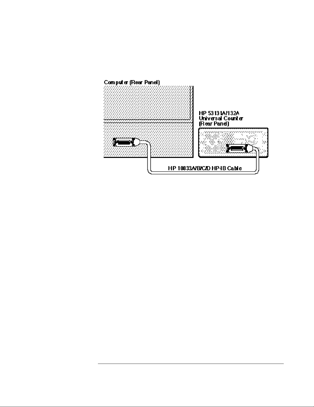
Chapter 3 Programming Your Universal Counter for Remote Operation
GPIB
Configuring the GPIB
To Connect the Counter to a Computer
Connect the Counter to a computer by simply installing an GPIB cable (such as
an Agilent 10833A cable) between the two units as shown in Figure 3-1.
Figure 3-1. GPIB Interconnection
Remote/Local Operation
At power-up, the Counter is under front-panel (local) control. Once in remote,
the Counter settings cannot be affected by the front-panel controls. The Save &
Print key may be used to manually return to local control (only if local-lockout
is off).
3-6 Programming Guide
Page 77

Chapter 3
Overview of Command Types and Formats
There are two types of Agilent 53131A/132A programming commands: IEEE
488.2 Common Commands and Standard Commands for Programmable
Instruments (SCPI). The IEEE 488.2 Common Commands control and manage
communications between theAgilent 53131A/132A and the controller or
personal computer. The SCPI commands control instrument functions. The
format of each type of command is described in the following paragraphs. (Refer
to
Chapter 2, “Command Summary,” for SCPI conformance information.)
Common Command Format
The IEEE 488.2 Standard defines the Common commands as commands that
perform functions like reset, self-test, status byte query, and identification.
Common commands always begin with the asterisk (*) character, and may
include parameters. The command keyword is separated from the first parameter
by a space character. Some examples of Common commands are as follows:
*RST *IDN? *RCL 1
SCPI Command and Query Format
SCPI commands perform functions like instrument setup. A subsystem command
has a hierarchical structure that usually consists of a top level (or root) keyword,
one or more lower-level keywords, and parameters. The following example
shows a command and its associated query:
:INPut:COUPling AC
:INPut:COUPling?
INPut is root-level keyword with COUPling the second level keyword, and AC is
the command parameter.
Programming Guide 3-7
Page 78
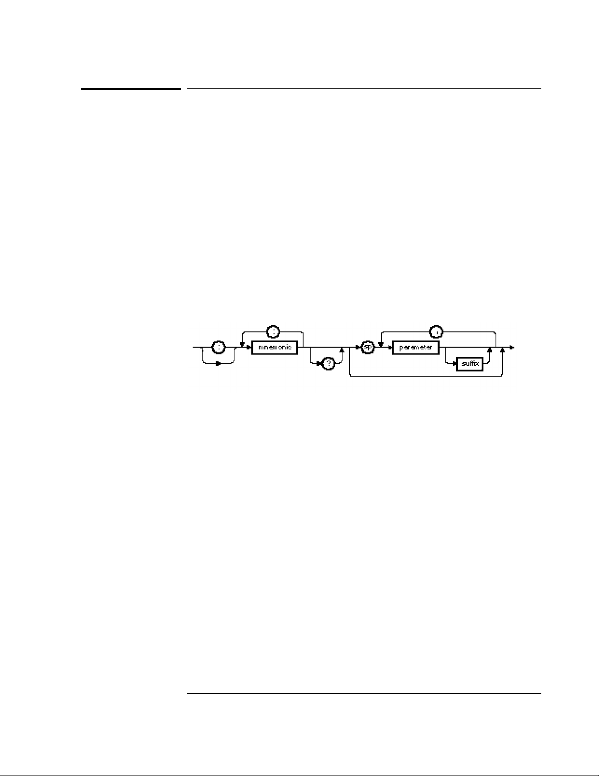
Chapter 3 Programming Your Universal Counter for Remote Operation
Elements of SCPI Commands
Elements of SCPI Commands
A program command or query is composed of functional elements that include a
header (or keywords with colon separators), program data, and terminators.
These elements are sent to the Counter over the
GPIB as a sequence of ASCII data messages. Examples of a typical Common
Command and Subsystem Command are:
OUTPUT 712;"*CLS"
OUTPUT 712;":INP1:COUP AC;IMP 1.0 MOHM"
Subsystem Command Syntax
Figure 3-2 shows the simplified syntax of a Subsystem Command. You must use
a space (SP) between the last command mnemonic and the first parameter in a
Subsystem Command. Note that if you send more than one parameter with a
single command, you must separate adjacent parameters with a comma.
NOTE: sp = space. ASCII character decimal 32
Figure 3-2. Simplified Program Command Syntax Diagram
Common Command Syntax
Figure 3-3 shows the simplified syntax of a Common Command. You must use a
space (SP) between the command mnemonic and the parameter in a Common
Command.
3-8 Programming Guide
Page 79
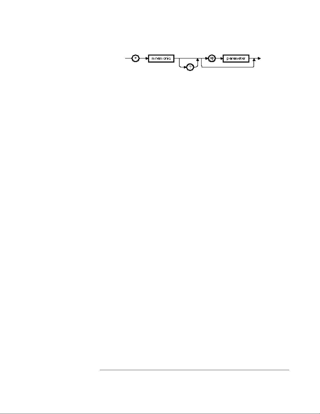
Chapter 3
NOTE: sp = space. ASCII character decimal 32
Figure 3-3. Simplified Common Command Syntax Diagram
Abbreviated Commands
The command syntax shows most keywords as a mixture of upper and lower case
letters. Upper case letters indicate the abbreviated spelling for the command. For
better program readability, you may send the entire keyword. The Agilent
53131A/132A accepts either command form and is not case sensitive.
For example, if the command syntax shows CALCulate, then CALC and
CALCULATE are both acceptable forms. Other forms of CALCulate, such as
CALCU or CALCULA will generate an error. You may use upper and/or lower
case letters. Therefore, CALCULATE, calculate, and CaLcUlAtE are all
acceptable.
Keyword Separator
A colon (:) always separates one keyword from the next lower-level keyword as
shown below:
:INPut:COUPling?
Optional Keyword
Optional keywords are those which appear in square brackets ([ ]) in the
command syntax. (Note that the brackets are not part of the command and are
not sent to the Counter.)
Suppose you send a second level keyword without the preceding optional
keyword. In this case, the Counter assumes you intend to use the optional
keyword and responds as if you had sent it.
Programming Guide 3-9
Page 80

Chapter 3 Programming Your Universal Counter for Remote Operation
Elements of SCPI Commands
Examine the portion of the [:SENSe] subsystem shown below:
[:SENSe]
:FREQuency
:ARM
:STOP
:SOURce EXTernal
The root-level keyword [:SENSe] is an optional keyword. To set the Counter’s
frequency stop arm to external, you can use either of the following:
:SENS:FREQ:ARM:STOP:SOUR EXT
or
:FREQ:ARM:STOP:SOUR EXT
Implied Channel (Optional Numeric Keyword Suffix)
Some commands allow specifying a channel with an optional numeric keyword
suffix. These commands will show the channel numbers within square brackets.
The brackets are not part of the command and are not sent to the Counter.
For example, :INPut[1|2]:COUPling AC | DC represents coupling commands for
channels 1 and 2:
:INPut[1]:COUPling AC | DC
:INPut2:COUPling AC | DC
If you do not specify the channel number, the implied channel is 1. For example,
you can send either of the following to configure
channel 1’s coupling to AC:
:INPut1:COUPling AC
or
:INPut:COUPling AC
3-10 Programming Guide
Page 81
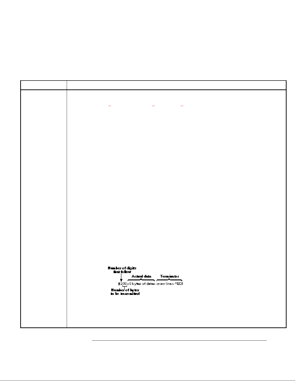
Chapter 3
Parameter Types
Table 3-1 contains explanations and examples of parameter types. Parameter types may
be numeric value, Boolean, literal, NRf, string, non-decimal numeric, or arbitrary block.
Table 3-1. Command and Query Parameter Types
TYPE EXPLANATIONS AND EXAMPLES
<numeric value>
Accepts all commonly used decimal representation of numbers including optional signs, decimal
points, and scientific notation:
123, 123e2, -123, -1.23e2, .123, 1.23e-2, 1.23000E-01.
Special cases include MINimum and MAXimum as follows:
MINimum selects minimum value available.
MAXimum selects maximum value available.
Queries using MINimum or MAXimum return the associated numeric value.
<Boolean>
<literal>
<NRf>
<string>
<non-decimal
numeric>
<arbitrary block>
Represents a single binary condition that is either true or false:
1 or ON, 0 or OFF (Query response returns only1 or 0.)
An <NRf> is rounded to an integer. A non-zero value is interpreted as 1.
Selects from a finite number of choices. These parameters use mnemonics to represent each valid
setting. An example is the INPut:COUPling AC | DC command parameters (AC | DC).
Flexible numeric representation. Only positive integers are used for NRf parameters in the Counter.
A string parameter is delimited by either single quotes or double quotes. Within the quotes, any
characters in the ASCII 7-bit code may be specified.
The following BASIC program statement sends a command containing a <string> parameter:
OUTPUT 703;"FUNC ‘FREQ’"
Format for specifying hexadecimal (#H1F), octal (#Q1077), and binary (#B10101011) numbers using
ASCII characters. May be used in :STATus subsystem commands.
The syntax is a pound sign (#) followed by a non-zero digit representing the number of digits in the
subsequent decimal integer. The decimal integer specifies the number of
8-bit data bytes being sent. This is followed by the actual data. The terminator is a line feed asserted
with EOI. For example, for transmitting 8 bytes of data, the format could be:
The “2” indicates the number of digits that follow and the two digits “08” indicate the number of data
bytes to be transmitted.
A zero-length block has the format: #0<new line>^EOI
<new line> is defined as a single ASCII-encoded byte corresponding to 10 decimal.
Programming Guide 3-11
Page 82

Chapter 3 Programming Your Universal Counter for Remote Operation
Elements of SCPI Commands
Parameter Separator
If you send more than one parameter with a single command, you must separate
adjacent parameters with a comma.
Query Parameters
All selectable <numeric value> parameters can be queried to return the minimum
or maximum values they are capable of being set to by sending a MINimumor
MAXimum parameter after the “?.” For example, consider the
INPut:IMPedance? query.
If you send the query without specifying a parameter (INP:IMP?), the present
impedance value is returned. If you send the MIN parameter (using INP:IMP?
MIN), the command returns the minimum level currently available. If you send
the MAX parameter, the command returns the maximumlevel currently
available. Be sure to place a space between the question mark and the parameter.
Suffixes
A suffix is the combination of suffix elements and multipliers that can be used to
interpret the <numeric value> sent. If a suffix is not specified, the Counter
assumes that <numeric value> is unscaled (that is, Volts, seconds, etc.)
For example, the following two commands are equivalent:
OUTPUT 703;"INP:IMP 1 MOHM"
OUTPUT 703;"INP:IMP 1E+6"
Suffix Elements
Suffix elements, such as HZ (Hertz), S (seconds), V (volts),
OHM (Ohms), PCT (percent), and DEG (degrees) are allowed within this
format.
3-12 Programming Guide
Page 83

Chapter 3
Suffix Multipliers
Table 3-2 lists the suffix multipliers that can be used with suffix elements
(except PCT and DEG).
Table 3-2. Suffix Multipliers
DEFINITION MNEMONIC NAME
1E18 EX ETA
1E15 PE PETA
1E12 T TERA
1E9 G GIGA
1E6 MA ( or M for OHM and HZ)* MEGA
1E3 K KILO
1E-3 M (except for OHM and HZ)* MILLI
1E-6 U MICRO
1E-9 N NANO
1E-12 P PICO
1E-15 F FEMTO
1E-18 A ATTO
*The suffix units, MHZ and MOHM, are special cases that should not be confused with
<suffix multiplier>HZ and <suffix multiplier>OHM.
Command Terminator
A command may be terminated with a <new line> (ASCII character decimal 10),
an EOI (End-of-Identify) asserted concurrent with last byte, or an EOI asserted
concurrent with a <new line> as the last byte.
Programming Guide 3-13
Page 84
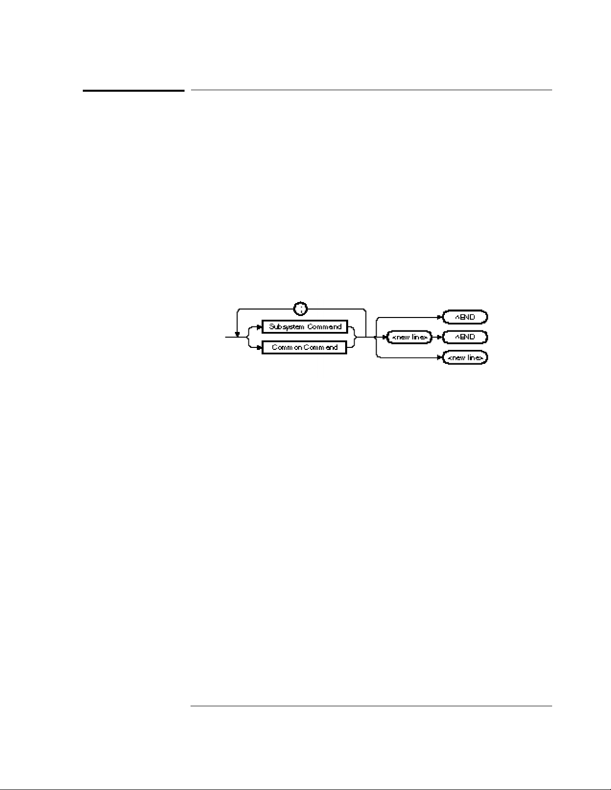
Chapter 3 Programming Your Universal Counter for Remote Operation
Using Multiple Commands
Using Multiple Commands
Program Messages
Program Messages are a combination of one or more properly formatted SCPI
Commands. Program messages always go from a computer to the Counter. They
are sent to the Counter over the Counter’s GPIB as a sequence of ASCII data
messages.
Program Message Syntax
Figure 3-4 shows the simplified syntax of a program message. You can see
Common Commands and Subsystem Commands in the same program message.
If you send more than one command in one message, you must separate adjacent
commands with a semicolon.
NOTE:
<new line> = ASCII character decimal 10
^END = EOI asserted concurrent with last byte
Figure 3-4. Simplified Program Message Syntax Diagram
When using IEEE 488.2 Common commands with SCPI Subsystem commands
on the same line, use a semicolon between adjacent commands. For example:
*RST;:INP:COUP AC
When multiple subsystem commands are sent in one program message, the first
command is always referenced to the root node. Subsequent commands,
separated by “;”, are referenced to the same level as the preceding command if
no “:” is present immediately after the command separator (the semicolon).
3-14 Programming Guide
Page 85

Chapter 3
For example, sending :INP:COUP AC;IMP 50 is equivalent to sending:
:INP:COUP AC
:INP:IMP 50
or
:INP:COUP AC;:INP:IMP 50
The “:” must be present to distinguish another root level command. For example:
:INP:COUP AC;:INIT:CONT OFF
is equivalent to sending:
:INP:COUP AC
:INIT:CONT OFF
If the “:”(which is following the “;” and is in front of INIT) is omitted, the
Counter assumes that the second command is “:INP:INIT:CONT OFF” and
generates a syntax error.
Programming Guide 3-15
Page 86
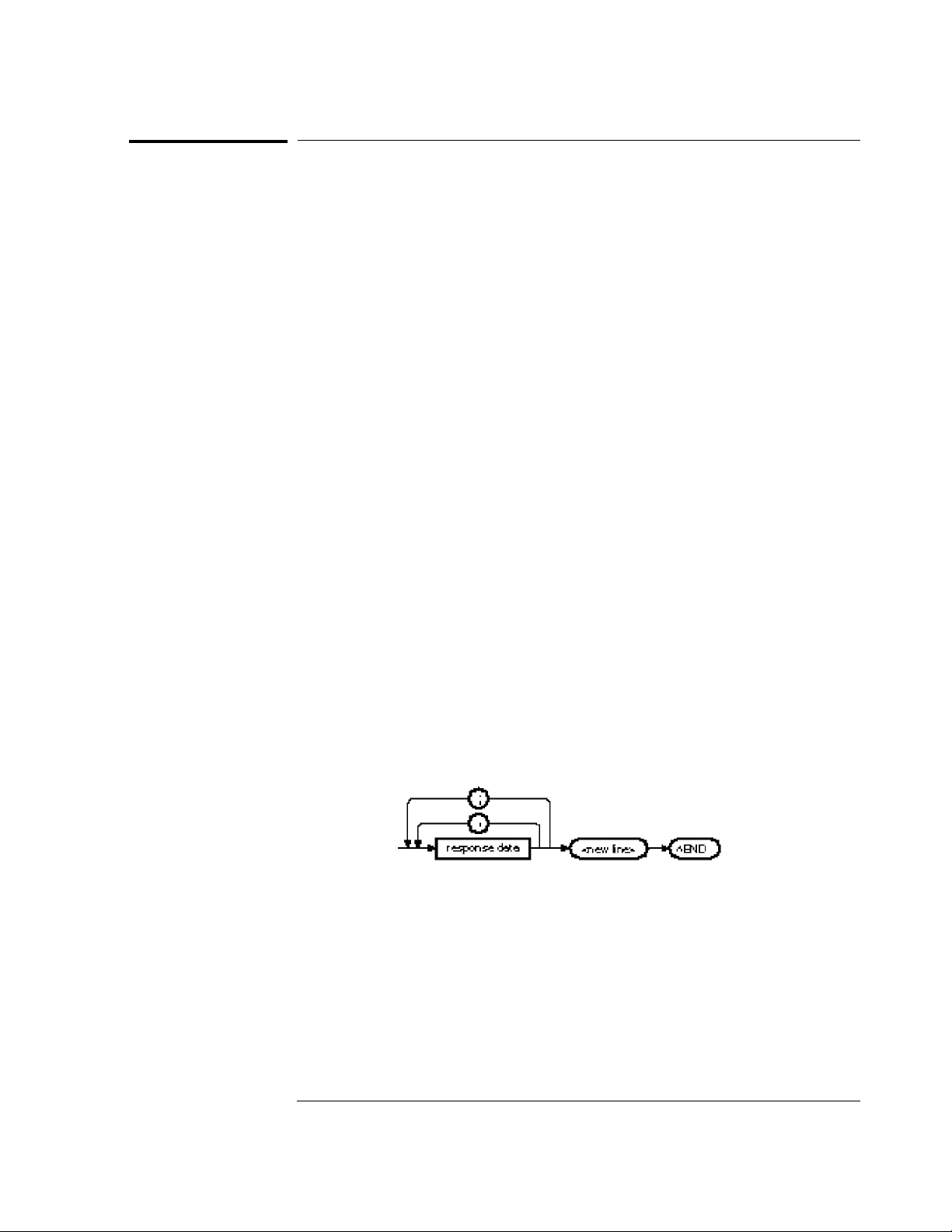
Chapter 3 Programming Your Universal Counter for Remote Operation
Overview of Response Message Formats
Overview of Response Message Formats
Response Messages
Response messages are data sent from the Counter to a computer in response to a
query. (A query is a command followed by a question mark. Queries are used to
find out how the Counter is currently configured and to transfer data from the
Counter to the computer.)
After receiving a query, the Counter interrogates the requested configuration and
places the response in its GPIB output queue.
The output message remains in the queue until it is read or another command is
issued. When read, the message is transmitted across the GPIB to the computer.
You read the message by using some type of enter statement that includes the
device address and an appropriate variable. Use a print statement to display the
message. The followingBASIC example illustrates how to query the Counter
and display the message:
10 OUTPUT 703;":INP:COUP?"
20 ENTER 703; A$
30 PRINT A$
40 END
Response Message Syntax
Figure 3-5 shows the simplified syntax of a Response Message. Response
messages may contain both commas and semicolon separators. When a single
query command returns multiple values, a comma is used to separate each item.
When multiple queries are sent in the same program message, the groups of data
corresponding to each query are separated by a semicolon. Note that a <new
line> ^END is always sent as a response message terminator.
NOTE:
<new line> = ASCII character decimal 10
^END = EOI asserted concurrent with last byte
; = multiple response separator (ASCII character decimal 59)
, = data separator within a response (ASCII character decimal 44)
Figure 3-5. Simplified Response Message Syntax Diagram
3-16 Programming Guide
Page 87
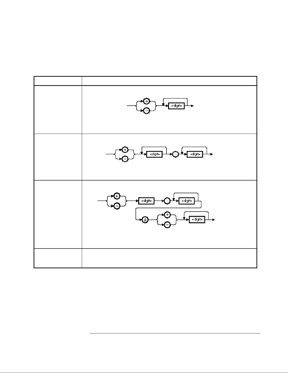
Chapter 3
Response Message Data Types
Table 3-3 contains explanations of response data types.
Table 3-3. Response Message Data Types
Type Description
<NR1> This numeric representation has an implicit radix point.
maximum number of characters in <NR1> response data is 17 (maximum
16 digits, 1 sign).
<NR2> This numeric representation has an explicit radix point.
The
The maximum number of characters in <NR2> response data is 17 (maximum
15 mantissa digits, 1 sign, 1 decimal point).
<NR3> This numeric representation has an explicit radix point and an exponent.
The maximum number of characters in <NR3> response data is 22 (maximum
15 mantissa digits, 2 signs, 1 decimal point, 1 ‘E’ character, 3 exponent digits).
Not a Number Not a Number is represented by the value 9.91E37. (Not a Number is defined in
IEEE 754). The Counter responds with this numeric value when queried for a
floating point number it cannot provide. This value will be formatted as an <NR3>.
Programming Guide 3-17
Page 88
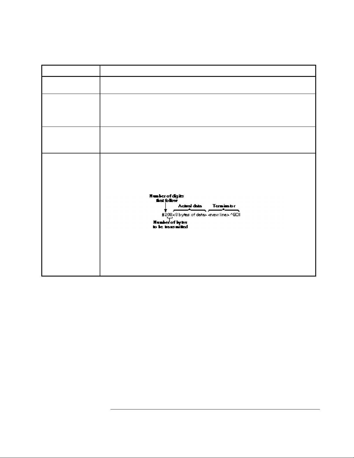
Chapter 3 Programming Your Universal Counter for Remote Operation
Overview of Response Message Formats
Table 3-3. Response Message Data Types (Continued)
Type Description
<Boolean> A single ASCII-encoded byte, 0 or 1, is returned for the query of settings that use
<Boolean> parameters.
<literal> ASCII-encoded bytes corresponding to the short form of the literal used as the
command parameter.
For example, if the :CALC3:AVER:TYPE MAXimum command is sent to the
Counter, the :CALC3:AVER:TYPE? response would be MAX.
<string> A string response consists of ASCII characters enclosed by double quotes.
For example, string data is used for the “<error description>” portion of
:SYST:ERR? response and for [:SENS]:FUNC? response.
<definite length
block>
The syntax is a pound sign (#) followed by a non-zero digit representing the
number of digits in the subsequent decimal integer. The decimal integer specifies
the number of 8-bitdata bytes being sent. This is followed bythe actual data. The
terminator is a line feed asserted with EOI. For example, for transmitting 8 bytes
of data, the format might be:
The “2” indicates the number of digits that follow and the two digits “08” indicate
the number of data bytes to be transmitted.
A zero-length block has the format: #0<new line>^EOI
<new line>is defined as a single ASCII-encoded byte corresponding to
10 decimal.
3-18 Programming Guide
Page 89

Chapter 3
Status Reporting
The Agilent 53131A/132A status registers conform to the SCPI and IEEE 488.2
standards.
Figure 3-6 shows all the status system register groups and queues in the Counter.
This is a high level drawing that does not show all the registers that are
contained in each group. It is intended as a guide to the bits used in each of these
register groups to monitor the Counter’s status. Note that besides the Operation
Status and the Questionable Data/Signal Register groups, a summary of the
Standard Status Structure Registers (defined by IEEE 488.2-1987) is shown.
Refer to the section in this chapter titled “How to Program the Counter for Status
Reporting” and the flowchart in Figure 3-10 for detailed information on
programming the status reporting system.
Programming Guide 3-19
Page 90

Chapter 3 Programming Your Universal Counter for Remote Operation
Status Reporting
Figure 3-6. Agilent 53131A/132A SCPI Status Reporting Summary
Functional Diagram
3-20 Programming Guide
Page 91
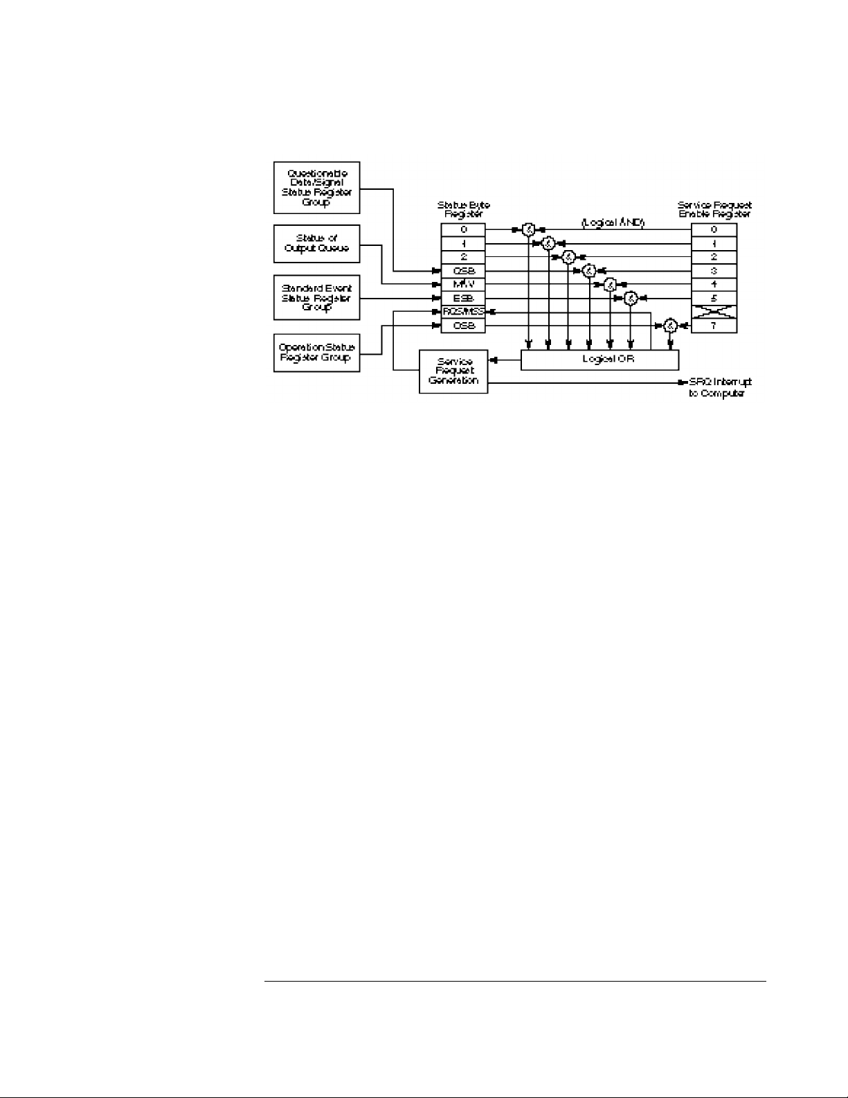
Chapter 3
Status Byte Register and Service Request Enable Register
Figure 3-7. Status Byte and Service Request Enable
Status Byte Register
The Status Byte Register is the summary-level register in the status reporting
structure. It contains summary bits that monitor activity in the other status
registers and queues as shown in Figure 3-7.
The Status Byte Register is a live register—its summary bits are set TRUE or
FALSE (one or zero) by the presence or absence of the condition which is being
summarized.
The Status Byte Register can be read with either a serial poll or the *STB?
query.
The Status Byte Register is altered only when the state of the overlying status
data structures is altered.
The entire Status Byte Register can be cleared by sending the *CLS command,
by itself in a program message, to the Counter.
Table 3-4 lists the Status Byte Register bits and briefly describes each bit.
Programming Guide 3-21
Page 92

Chapter 3 Programming Your Universal Counter for Remote Operation
Status Reporting
Table 3-4. Status Byte Register
BIT WEIGHT SYMBOL DESCRIPTION
0 Not used
1 Not used
2 Not used
Questionable Data/Signal Status Register
3 8 QSB
4 16 MAV Message Available Summary Bit
5 32 ESB Standard Event Status Register Summary Bit
6 64 RQS/MSS Request Service/Master Status Summary Bit
7 128 OSB Operation Status Register Summary Bit
Summary Bit
A detailed description of each bit in the Status Byte Register follows:
● Bits 0–2 are not used.
● Bit 3 (QSB) summarizes the Questionable Data/Signal Status Event
Register.
This bit indicates whether or not one or more of the enabled
Questionable Data/Signal events have occurred since the last reading or
clearing of the Questionable Data/Signal Status Event Register.
This bit is set TRUE (one) when an enabled event in the Questionable
Data/Signal Status Event Register is set TRUE. Conversely, this bit is
set FALSE (zero) when no enabled events are set TRUE.
● Bit 4 (MAV) summarizes the Output Queue.
This bit indicates whether or not the Output Queue is empty.
This bit is set TRUE (one) when the Counter is ready to accept a request
by the external computer to output data bytes; that is, the Output Queue
is not empty. This bit is set FALSE (zero) when the Output Queue is
empty.
3-22 Programming Guide
Page 93

Chapter 3
● Bit 5 (ESB) summarizes the Standard Event Status Register.
This bit indicates whether or not one of the enabled Standard Event
Status Register events have occurred since the last reading or clearing of
the Standard Event Status Register.
This bit is set TRUE (one) when an enabled event in the Standard Event
Status Register is set TRUE. Conversely, this bit is set FALSE (zero)
when no enabled events are set TRUE.
● Bit 6 (RQS/MSS) summarizes IEEE 488.1 RQS and Master Summary
Status.
When a serial poll is used to read the Status Byte Register,
the RQS bit indicates if the device was sending SRQ TRUE. The RQS
bit is set FALSE by a serial poll.
When *STB? is used to read the Status Byte Register, the MSS bit
indicates the Master Summary Status. The MSS bit indicates whether or
not the Counter has at least one reason for requesting service.
● Bit 7 (OSB) summarizes the Operation Status Event Register.
This bit indicates whether or not one or more of the enabled Operation
events have occurred since the last reading or clearing of the Operation
Status Event Register.
This bit is set TRUE (one) when an enabled event in the Operation
Status Event Register is set TRUE. Conversely, this bit is set FALSE
(zero) when no enabled events are set TRUE.
Service Request Enable Register
The Service Request Enable Register selects which summary bits in the Status
Byte Register may cause service requests as shown in
Figure 3-7.
Use *SRE to write to this register and *SRE? to read this register.
Use *SRE 0 to clear the register. A cleared register does not allow status
information to generate the service requests. (Power-on also clears this register.)
Programming Guide 3-23
Page 94
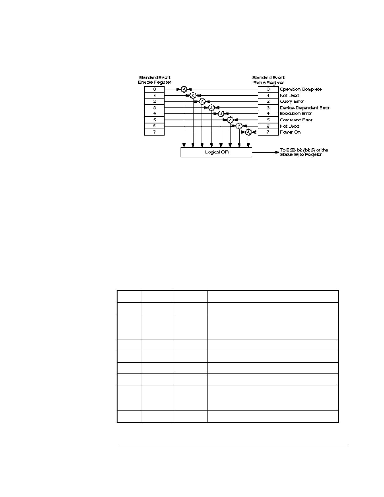
Chapter 3 Programming Your Universal Counter for Remote Operation
Status Reporting
Standard Event Status Register Group
Figure 3-8. Standard Event Status Reporting
Standard Event Status Register
The Standard Event Status Register contains bits that monitor specific IEEE
488.2-defined events as shown in Figure 3-8.
Use *ESR? to read this register.
Use *ESR? or *CLS to clear this register.
Table 3-5 lists the Standard Event Status Register bits and briefly describes each
bit.
Table 3-5. Standard Event Status Register
BIT WEIGHT SYMBOL DESCRIPTION
0 1 OPC Operation Complete
1 (RQC) Not used because this instrument cannot
request permission to become active
IEEE 488.1 controller-in-charge.
2 4 QYE Query Error
3 8 DDE Device-Specific Error
4 16 EXE Execution Error
5 32 CME Command Error
6 (URQ) Not used because this instrument does not
define any local controls as “User Request”
controls.
7 128 PON Power On
3-24 Programming Guide
Page 95

Chapter 3
A detailed description of each bit in the Standard Event Status Register follows:
● Bit 0 (Operation Complete) is an event bit which is generated in
response to the *OPC command. This bit indicates that the Counter has
completed all pending operations.
If there are no pending operations at the time *OPC executes, this bit sets
immediately.
If there is a pending operation at the time *OPC executes, this event bit
sets when the pending operation condition transistions from TRUE to
FALSE.
If
the :TRIGger:COUNt:AUTO is OFF, or
statistics are disabled, or
the function is set to Totalize or Voltage Peaks,
then the pending operation condition is set TRUE when either: 1) a single
measurement is initiated, or 2) a continuous measurement cycle is
initiated. The pending operation condition is set FALSE when the
measurement cycle terminates.
If
the TRIGger:COUNt:AUTO is ON, and
statistics are enabled, and
the function is set to Totalize or Voltage Peaks,
then the pending operation condition is set TRUE when a block of
measurements is initiated. The pending operation condition is set
FALSE when the block of measurements completes; that is, when the
last measurement in the block completes.
Bit 1 is not used.
? ● Bit 2 (Query Error) is an event bit which indicates that either 1) an
attempt was made to read the Output Queue when it was empty or 2)
data in the Output Queue has been lost.
Errors -400 through -499 are query errors.
Programming Guide 3-25
Page 96

Chapter 3 Programming Your Universal Counter for Remote Operation
Status Reporting
● Bit 3 (Device-Specific Error) is an event bit which indicates an operation
did not properly complete due to some condition of the Counter.
Errors -300 through -399 and all those with positive error numbers
(+2000 through ...) are device-specific errors.
● Bit 4 (Execution Error) is an event bit which indicates that a command
could not be executed 1) because the parameter was out of range or
inconsistent with the Counter’s capabilities, or 2) because of some condition
of the Counter.
Errors -200 through -299 are execution errors.
● Bit 5 (Command Error) is an event bit which indicates one of the
following has occurred: 1) an IEEE 488.2 syntax error, 2) a semantic error
indicating an unrecognized command, or 3) a Group Execute Trigger was
entered into the input buffer inside of a program message.
● Bit 6 is not used.
● Bit 7 (Power On) is an event bit which indicates that an off-to-on
transition has occurred in the Counter’s power supply.
Standard Event Status Enable Register
The Standard Event Status Enable Register selects which events in the Standard
Event Status Register are reflected in the ESB summary bit (bit 5) of the Status
Byte Register as shown in
Figure 3-8.
Use *ESE to write to this register and *ESE? to read this register.
Use *ESE 0 to clear the register. (Power-on also clears this register.)
3-26 Programming Guide
Page 97
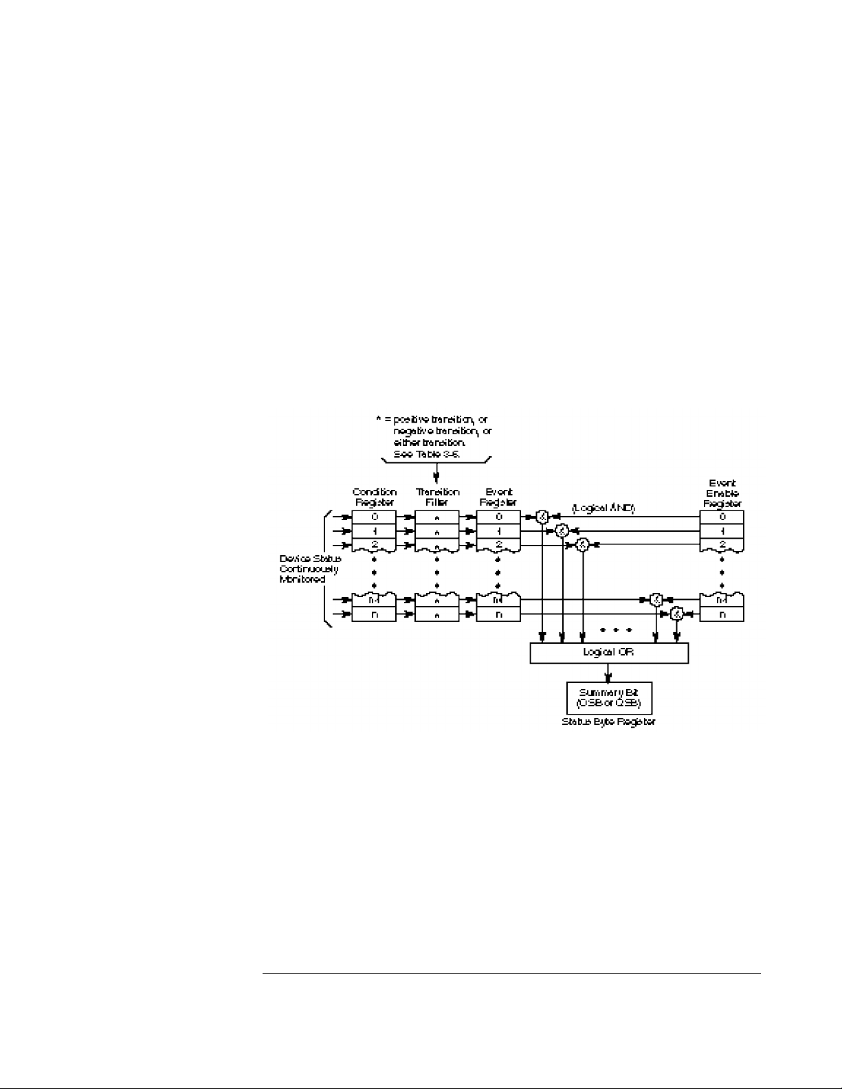
Chapter 3
Operation Status Register Group and Questionable Data/Signal
Status Register Group
The Operation Status Register Group and the Questionable Data/Signal Status
Register Group each have a complete set of registers that consists of the
following:
● a condition register
● a positive transition filter register
● a negative transition filter register
● an event register
● an event enable register
Figure 3-9 shows the model that these register groups follow.
Figure 3-9. Operation and Questionable Status Reporting Model
Programming Guide 3-27
Page 98

Chapter 3 Programming Your Universal Counter for Remote Operation
Status Reporting
Condition Register
A condition register continuously monitors the hardware and firmware status of
the Counter. There is no latching or buffering for this register; it is updated in
real time. Reading a condition register does not change its contents.
To read the condition registers use:
:STATus:OPERation:CONDition?
:STATus:QUEStionable:CONDition?
Transition Filter
A transition filter specifies the transition criteria for setting event bits TRUE.
When the transition filter specifies a positive transition, the event becomes
TRUE when its associated condition makes a FALSE to TRUE transition only.
When the transition filter specifies a negative transition, the event becomes
TRUE when its associated condition makes a TRUE to FALSE transition only.
When the transition filter specifies either a positive or a negative transition, the
event becomes TRUE when its associated condition makes either a FALSE to
TRUE or a TRUE to FALSE transition.
A transition filter is defined by a positive and negative transition filter register.
Table 3-6 describes how the transition filter registers define the transition
criteria for setting an event bit TRUE.
Table 3-6. Transition Filter Definition
Positive
Transition
Filter Bit
TRUE FALSE positive transition
FALSE TRUE negative transition
TRUE TRUE either a positive or negative transition
FALSE FALSE neither transition (event reporting is disabled)
Negative
Transition
Filter Bit
Transition Which Causes the
Event-Bit to be set TRUE
3-28 Programming Guide
Page 99

Chapter 3
Transition filters are unaffected by *CLS or queries. Transition filters are set to
default values by :STATus:PRESet and power-on.
To write to the transitions filter registers use:
:STATus:OPERation:PTRansition
:STATus:OPERation:NTRansition
:STATus:QUEStionable:PTRansition
:STATus:QUEStionable:NTRansition
To read the transition filter registers use:
:STATus:OPERation:PTRansition?
:STATus:OPERation:NTRansition?
:STATus:QUEStionable:PTRansition?
:STATus:QUEStionable:NTRansition?
Event Register
An event register captures changes in conditions.
An event register bit (event bit) shall be set TRUE when an associated event
occurs. These bits, once set, are “sticky.” That is, they cannot be cleared even if
they do not reflect the current status of a related condition, until they are read.
To read the event registers use:
:STATus:OPERation[:EVENt]?
:STATus:QUEStionable[:EVENt]?
Use event register queries or *CLS to clear event registers.
Event Enable Register
An event enable register selects which event bits in the corresponding event
register can generate a summary bit.
To write the event enable registers use:
:STATus:OPERation:ENABle
:STATus:QUEStionable:ENABle
To read the event enable registers use:
:STATus:OPERation:ENABle?
:STATus:QUEStionable:ENABle?
The event enable registers are cleared by :STATus:PRESet and power-on.
Programming Guide 3-29
Page 100

Chapter 3 Programming Your Universal Counter for Remote Operation
Status Reporting
Operation Status Register Group
The Operation Status Register Group monitors conditions which are part of the
Counter’s normal operation.
Table 3-7 lists the Operation Status Register bits and briefly describes each bit.
Table 3-7. Operation Status Register
BIT WEIGHT DESCRIPTION
0 1 Calibrating
1 Not used
2 Not used
3 Not used
4 16 Measuring
5 Not used
6 Not used
7 Not used
8 256 Computing Statistics
9 512 Using Internal Reference
10 1024 In Limit Event
11–14 Not used
15 Not used since some controllers may have difficulty
reading a 16-bit unsigned integer. The value of this bit
shall always be 0.
A detailed description of each bit in the Operation Status Register follows:
● Bit 0 (Calibrating) is a condition bit which indicates the Counter is
currently performing a (front-panel invoked or GPIB invoked) calibration.
The condition bit is TRUE (one) during a calibration and FALSE (zero)
otherwise.
3-30 Programming Guide
 Loading...