


Specifications describe the instrument’s
warranted performance over the
temperature range of 0 °C to 40 °C
(except as noted). Supplemental
characteristics are intended to provide
information that is useful in applying
the instrument by giving non-warranted
performance parameters. These are
denoted as typical, typically, nominal,
or approximate. Warm-up time must
be greater than or equal to 30 minutes
after power on for all specifications.
Agilent
4396B 1.8 GHz
Network/Spectrum/Impedance Analyzer
Data Sheet
Network Measurement
Source characteristics
Frequency characteristics (Option 4396B-800)
Range . . . . . . . . . . . . . . . . . . . . . . . . . . . . . . . . . . . . . . . . .100 kHz to 1.8 GHz
Resolution . . . . . . . . . . . . . . . . . . . . . . . . . . . . . . . . . . . . . . . . . . . . . .≤ 1 mHz
Frequency reference
Accuracy
23 ±5 °C, referenced to 23 °C . . . . . . . . . . . . . . . . . . .< ±5.5 ppm/year
Aging . . . . . . . . . . . . . . . . . . . . . . . . . . . . . . . . . .< ±2.5 ppm/year typically
Initial achievable accuracy . . . . . . . . . . . . . . . . . . . . . . .< ±1.0 ppm typically
Temperature stability
23 ±5 °C, referenced to 23 °C . . . . . . . . . . . . . . . . . .< ±2 ppm typically
Precision frequency reference (Option 4396B-1D5)
Accuracy
0 °C to 40 °C, referenced to 23 °C . . . . . . . . . . . . . . .< ±0.13 ppm/year
Aging . . . . . . . . . . . . . . . . . . . . . . . . . . . . . . . . . .< ±0.1 ppm/year typically
Initial achievable accuracy . . . . . . . . . . . . . . . . . . . . . .< ±0.02 ppm typically
Temperature stability
0 °C to 40 °C, referenced to 23 °C . . . . . . . . . . . .< ±0.01 ppm typically

2
Output Characteristics
Power range . . . . . . . . . . . . . . . . . . . . . . . . . . . . . . . . . . . . . .–60 dBm to +20 dBm
Power sweep range . . . . . . . . . . . . . . . . . . . . . . . . . . . . . . . . . . . . . . . . . . . . .20 dB
Power sweep linearity
23 ±5 °C, 50 MHz, relative to stop power . . . . . . . . . . . . . . . . . . . . . .±0.5 dB
Resolution . . . . . . . . . . . . . . . . . . . . . . . . . . . . . . . . . . . . . . . . . . . . . . . . . . .0.1 dB
Flatness
23 ±5 °C, relative to 50 MHz, 0 dBm output . . . . . . . . . . . . . . . . . . . . .±1.0 dB
Level accuracy
23 ±5 °C, 50 MHz, 0 dBm output . . . . . . . . . . . . . . . . . . . . . . . . . . .< ± 0.5 dB
Level linearity
Output power Linearity
1
–20 dBm ≤ power ≤ +20 dBm ±0.7 dB
–40 dBm ≤ power < –20 dBm ±1.0 dB
–60 dBm ≤ power < –40 dBm ±1.5 dB
Spectral purity characteristics
Harmonics
+15 dBm output . . . . . . . . . . . . . . . . . . . . . . . . . . . . . . . . . . . . . . . .< –30 dBc
Non-harmonics spurious
+15 dBm output . . . . . . . . . . . . . . . . . . . . . . . . . . . . . . . . . . . . . . . .< –30 dBc
Noise sidebands
SPAN = 0, IFBW (or RBW) ≤ 3 kHz
frequency ≤ 1 GHz
≥ 10 kHz offset from carrier . . . . . . . . . . . . . . . .< –105 dBc/Hz typically
≥ 1 MHz offset from carrier . . . . . . . . . . . . . . . .< –110 dBc/Hz typically
frequency > 1 GHz . . . . . . . . . . . . .Add [20 log(frequency(GHz) )] typically
Impedance . . . . . . . . . . . . . . . . . . . . . . . . . . . . . . . . . . . . . . . . . . . . . .50 Ω nominal
Return loss
≤ 0 dBm,100 MHz < frequency ≤ 1.8 GHz . . . . . . . . . . . . . . .> 14 dB typically
≤ 0 dBm, 100 kHz ≤ frequency ≤ 100 MHz . . . . . . . . . . . . . . .> 23 dB typically
Connector . . . . . . . . . . . . . . . . . . . . . . . . . . . . . . . . . . . . . . . . . . . . .Type-N female
1. At 23 ±5 °C, relative to 0 dBm output

3
Receiver Characteristics
Input characteristics
Frequency range
IFBW ≤ 3 kHz . . . . . . . . . . . . . . . . . . . . . . . . .100 kHz to 1.8 GHz
IFBW = 10 kHz, 40 kHz . . . . . . . . . . . . . . . . . .1 MHz to 1.8 GHz
Full scale input level
R input . . . . . . . . . . . . . . . . . . . . . . . . . . . . . . . . . . . . . .+20 dBm
A, B inputs . . . . . . . . . . . . . . . . . . . . . . . . . . . . . . . . . . . .–5 dBm
IF bandwidth (IFBW) . . . . . . . . .10, 30, 100, 300, 1 k, 3 k, 10 k, 40 kHz
Noise level
Noise level Noise level
Frequency Input port IFBW = 10 Hz IFBW = 40 kHz
100 k ≤ freq. < 10 MHz R < –85 dBm < –50 dBm
100 k ≤ freq. < 10 MHz A, B < –110 dBm < –75 dBm
10 MHz ≤ freq. R < [ –100 + 3 f ] dBm
1
< [–65 + 3 f ] dBm
1
10 MHz ≤ freq. A, B < [ –125 + 3 f ] dBm
1
< [–90 + 3 f ] dBm
1
Input crosstalk
≥ 300 kHz
A to/from B . . . . . . . . . . . . . . . . . . . . . . . . . . . . . . . . . .< –100 dB
R to A, B . . . . . . . . . . . . . . . . . . . . . . . . . . . . . . . . . . . .< –120 dB
A, B to R . . . . . . . . . . . . . . . . . . . . . . . . . . . . . . . . . . . . . .< –80 dB
Source crosstalk (A, B)
≥ 300 kHz . . . . . . . . . . . . . . . . . . . . . . . . . . . .< –124 dB typically
Maximum safe input level . . . . . . . . . . .+20 dBm or ±25 Vdc typically
Connector . . . . . . . . . . . . . . . . . . . . . . . . . . . . . . . . . . .Type-N female
Impedance . . . . . . . . . . . . . . . . . . . . . . . . . . . . . . . . . . .50 Ω nominal
Return loss
frequency ≥ 500 kHz . . . . . . . . . . . . . . . . . . . . . . . . . . . . .> 20 dB
100 kHz ≤ frequency < 500 kHz . . . . . . . . . . . . .> 12 dB typically
3 MHz ≤ frequency ≤ 50 MHz . . . . . . . . . . . . . . > 35 dB typically
Multiplexer switching impedance change . . . . . . . . .< 1 Ω typically
1. f is measurement frequency (GHz).

4
Magnitude Characteristics
Absolute amplitude accuracy (R, A, B)
–20 dBm input, 23 ±5 °C . . . . . . . . . . . . . . .< ±1.5 dB (±0.9 dB typically)
Ratio accuracy (A/R, B/R)
–20 dBm input, 23 ±5 °C, IFBW ≤ 3 kHz
100 k ≤ frequency < 1 MHz . . . . . . . . . . . . .< ±1 dB (±0.6 dB typically)
frequency ≥ 1 MHz . . . . . . . . . . . . . . . . . .< ±0.5 dB (±0.3 dB typically)
Dynamic accuracy (A/R, B/R)
Input level
(relative to full scale input level)
1
Dynamic accuracy
2
0 dB < ±0.3 dB
–10 dB to –70 dB < ±0.05 dB
–80 dB < ±0.1 dB
–90 dB < ±0.3 dB
–100 dB < ±1.0 dB
–110 dB < ±0.8 dB typically
–120 dB < ±2.5 dB typically
Residual responses
A, B inputs, frequency ≥ 3 MHz . . . . . . . . . . . . . . . . .< –95 dBm typically
R input, frequency ≥ 3 MHz . . . . . . . . . . . . . . . . . . . .< –70 dBm typically
See “EMC” under “Others” in “Common Specifications for Network
and Spectrum Measurement.”
Trace noise
A/R, B/R measurement,
–10 dBm input, IFBW = 300 Hz . . . . . . . . . . .< 0.002 dB rms typically
Stability 0.01 dB/°C typically
Dynamic accuracy (dB)
Input level (dB)
Spec
Typical
1. Full scale input level = –5 dBm
2. At 23 ±5 °C, IFBW = 10Hz, R input = –35 dBm, Reference power level = –35 dBm
Figure 1. Magnitude dynamic accuracy

5
Phase Characteristics
Measurements format . . . . . . . . . . . . . . .Phase format, expanded phase format
Frequency response (deviation from linear phase) (A/R, B/R)
–20 dBm input, 23 ±5 °C, IFBW ≤ 3 kHz
100 k ≤ frequency < 1 MHz . . . . . . . . . . . . . . . . .< ±6 deg (±4 deg typically)
frequency ≥ 1 MHz . . . . . . . . . . . . . . . . . . . . . . . < ±3 deg (±2 deg typically)
Dynamic accuracy (A/R, B/R)
Input level
(relative to full scale input level)
1
Dynamic accuracy
2
0 dB < ±3 deg
–10 dB < ±0.6 deg
–20 dB to –70 dB < ±0.3 deg
–80 dB < ±0.7 deg
–90 dB < ±2.3 deg
–100 dB < ±7 deg
–110 dB < ±8 deg typically
–120 dB < ±25 deg typically
Trace noise
A/R, B/R measurement,
–10 dBm input, IFBW = 300 Hz . . . . . . . . . . . .< 0.04 deg rms typically
Stability . . . . . . . . . . . . . . . . . . . . . . . . . . . . . . . . . . . . . . . 0.1 deg/°C typically
Dynamic accuracy (dB)
Input level (dB)
Spec
Typical
1. Full scale input level = –5 dBm
2. At 23 ±5 °C, IFBW = 10 Hz, R input = –35 dBm, Reference power level = –35 dBm
Figure 2. Phase dynamic accuracy

6
Group Delay Characteristics
Accuracy
In general, the following formula can be used to determine the accuracy,
in seconds, of a specific group delay measurement:
23 ±5 °C . . . . . . . . . . . . . . . . . . . . . . . . . . . . . . . . . . . . . . . . . . . . . . . . . . . . .
Depending on the aperture, input level, and device length, the phase
accuracy used in either incremental phase accuracy or worst case phase
accuracy.
Sweep Characteristics
Sweep type . . . . . . . . .Linear frequency, log frequency, power, list frequency
Trigger type . . . . . . . . . . . . . . . . .Hold, single, number of groups, continuous
Trigger source . . . . . . . . . . . . . . . . . .Free run, external, manual, GPIB (bus)
Event trigger . . . . . . . . . . . . . . . . . . . . . . . . . . . . . . . . . . . .On point, On sweep
phaseAccuracy(deg)
Aperture(Hz) x 360 deg)
Group delay accuracy (sec)
Aperture (Hz)
@ 1.8 GHz
with 7 mm full 2-port calibration
Device electrical length 10 m
with insertion loss of less than 1 dB
Figure 3. Typical group delay accuracy

7
Spectrum Measurement
Specifications in this section describe the instrument’s warranted performance
for spectrum measurement using S input (except as noted).
Frequency Characteristics
Frequency range . . . . . . . . . . . . . . . . . . . . . . . . . . . . . . . . . . . .2 Hz to 1.8 GHz
Frequency readout accuracy
. . . . . . . . . . . . . . . . . . .±((freq readout) x (freq ref accuracy) + RBW + ))
where NOP means number of display points
Frequency reference (Option 4396B-800)
Accuracy
23 ±5 °C, referenced to 23 °C . . . . . . . . . . . . . . . . . . . . .< ±5.5 ppm/year
Aging . . . . . . . . . . . . . . . . . . . . . . . . . . . . . . . . . . . .< ±2.5 ppm/year typically
Initial achievable accuracy . . . . . . . . . . . . . . . . . . . . . . . . . .< ±1 ppm typically
Temperature stability
23 ±5 °C, referenced to 23 °C . . . . . . . . . . . . . . . . . . .< ±2 ppm typically
Precision frequency reference (Option 4396B-1D5)
Accuracy
0 °C to 40 °C, referenced to 23 °C . . . . . . . . . . . . . . . . < ±0.13 ppm/year
Aging . . . . . . . . . . . . . . . . . . . . . . . . . . . . . . . . . . . .< ±0.1 ppm/year typically
Initial achievable accuracy . . . . . . . . . . . . . . . . . . . . . . . .< ±0.02 ppm typically
Temperature stability
0 °C to 40 °C, referenced to 23 °C . . . . . . . . . . . .< ±0.01 ppm typically
Resolution bandwidth (RBW)
Range . . . . . . . . . . . . . . . . . . . . . . . . . . . . . . . . . . .1 Hz to 3 MHz, 1-3-10 step
Selectivity (60 dB BW/3 dB BW)
RBW ≥ 10 kHz . . . . . . . . . . . . . . . . . . . . . . . . . . . . . . . . . . . . . . . . . . .< 10
RBW ≤ 3 kHz . . . . . . . . . . . . . . . . . . . . . . . . . . . . . . . . . . . . . . . . . . . . .< 3
Accuracy
RBW ≥ 10 kHz . . . . . . . . . . . . . . . . . . . . . . . . . . . . . . . . . . . . . . . . .< ±20%
RBW ≤ 3 kHz . . . . . . . . . . . . . . . . . . . . . . . . . . . . . . . . . . . . . . . . . .< ±10%
Video bandwidth
Range . . . . . . . . . . . . . .0.003 Hz to 3 MHz, 1-3-10 step, 1 ≤ RBW/VBW ≤ 300
SPAN
NOP

8
Noise sidebands
Offset from carrier Noise sidebands
1
≥ 1 kHz < –95 dBc/Hz
≥ 10 kHz < –105 dBc/Hz
≥ 1 MHz < –110 dBc/Hz
Residual FM
RBW ≤ 10 Hz
Option 4396B-800 . . . . . . . . . . . . .< 1 x f (GHz) Hz
pk-pk
in 10 sec typically
Frequency = 1 GHz . . . . . . . . . . . . . . . . . . . . . . . . . .< 1 Hz
pk-pk
typically
Option 4396B-1D5 . . . . . . . . . . .< 0.1 x f (GHz) HZ
pk-pk
in 10 sec typically
Frequency = 1 GHz . . . . . . . . . . . . . . . . . . . . . . . . < 0.1 Hz
pk-pk
typically
RBW ≤ 1 kHz . . . . . . . . . . . . . . . . . . . . . . . . .< 3 Hz
pk-pk
in 100 msec typically
Noise sideband (dBc/Hz)
Frequency offset (Hz)
Carrier frequency = 1 GHz
SPEC
TYPICAL
Figure 4. typical noise sidebands (with Option 4396B-1D5)
1. Center frequency ≤ 1 GHz. Add [20log(frequency(GHz))] for frequency > 1 GHz.

9
On-screen dynamic range
1 GHz center frequency, may be limited by average noise level.
Amplitude characteristics
Amplitude range . . . . . . . . . . . . . . . .Displayed average noise level to +30 dBm
Reference level range . . . . . . . . . . . . . . . . . . . . . . . . . . .–100 dBm to +30 dBm
(or equivalent in dBµV, dBV, V, W)
Scale
Log . . . . . . . . . . . . . . . . . . . . . . . . . . . . . . . . . . . . . .0.1 dB/div to 20 dB/div
Linear
Watt . . . . . . . . . . . . . . . . . . . . . . . . . . . . . . . . . . . . . . . . . .1.0 x 10
–12
W/div
Volt . . . . . . . . . . . . . . . . . . . . . . . . . . . . . . . . . . . . . . . . . . .1.0 x 10
–9
V/div
Measurement format . . . . . . . . . . . . . . . . . . . . . . .SPECTRUM or NOISE (/HZ)
Display unit . . . . . . . . . . . . . . . . . . . . . . . . . . . . .dBm, dBµV, dBV, Volts, Watts
On-screen dynamic range (dBc)
Offset frequency (Hz)
Figure 5. Typical on-screen dynamic range
10
Typical Dynamic Range
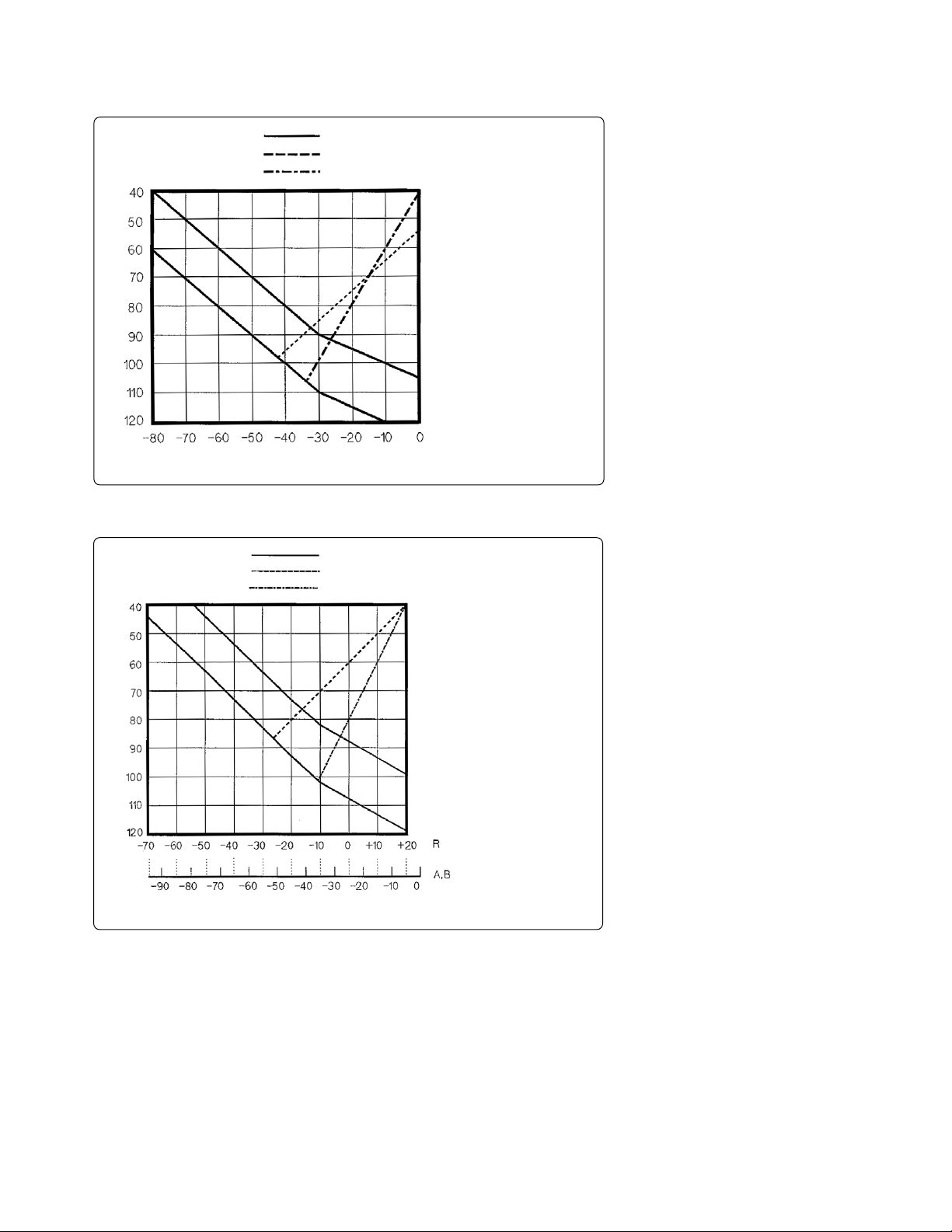
Figure 6. Typical dynamic range at S input
Figure 7. Typical dynamic range at R, A, and B inputs
Dynamic range (dB)
Input level (dBm)
Sensitivity
2nd harmonic distortion
3rd order inter-modulation distoration
Input attenuator = 10 dB
10 MHz ≤ frequency ≤ 1 GHz
100HzBW
1HzBW
Dynamic range (dB)
Input level (dBm)
Sensitivity
2nd harmonic distortion
3rd order inter-modulation distoration
10 MHz ≤ frequency ≤ 1 GHz
100HzBW
1HzBW

11
Spurious responses
Second harmonic distortion
≥ 10 MHz, –35 dBm mixer input . . . . . . . . . . . . . . . . . . . . . . . . .< –70 dBc
< 10 MHz, –35 dBm mixer input . . . . . . . . . . . . . . . . . . . . . . . . .< –60 dBc
Third order intermodulation distortion
each input mixer level of two tones = –30 dBm, separation ≥ 20 kHz
≥ 10 MHz . . . . . . . . . . . . . . . . . . . . . . . . . . . . . . . . . . . . . . . . . . .< –75 dBc
< 10 MHz . . . . . . . . . . . . . . . . . . . . . . . . . . . . . . . . . . . . . . . . . . .< –65 dBc
Other spurious
–30 dBm mixer input, offset ≥ 1 kHz . . . . . . . . . . . . . . . . . . . . . .< –70 dBc
Residual response
≥ 3 MHz, 0 dB attenuator . . . . . . . . . . . . . . . . . . . . . . . . . . . . . . .< –100 dBm
1 kHz ≤ frequency < 3 MHz, 0 dB attenuator . . . . . . . . . . . . . . . . .< –90 dBm
See “EMC” under “Others” in “Common Specifications for Network . . . . . . .
and Spectrum Measurement.”
Local oscillator feedthrough . . . .< –25 dBm input mixer level equivalent typically
Gain compression
≥ 10 MHz, input mixer level < –10 dBm . . . . . . . . . . . . . . .< 0.3 dB typically
Displayed average noise level
frequency ≥ 10 MHz,
ref. level ≤ –40 dBm, att. = 0 dB . . . . . . . . . . . < [–150 + 3f (GHz)] dBm/Hz
10 kHz ≤ frequency < 10 MHz,
ref. level ≤ –40 dBm, att. = 0 dB . . . . . . . . . . . . . . . . . . . . .< –125 dBm/Hz
Maximum safe input level
Average continuous power . . . . . . . . . . . . . . . . . . . . . . . . . . . . . .+30 dBm (1 W)
Peak pulse power
Pulse width < 10 µ s,
duty cycle < 1%, input attenuator ≥ 30 dB . . . . . . . . . .+50 dBm (100 W)
dc voltage . . . . . . . . . . . . . . . . . . . . . . . . . . . . . . . . . . . . . . . . . . . . . . . . .0 Vdc
Input attenuator
Range . . . . . . . . . . . . . . . . . . . . . . . . . . . . . . . . . . . .0 dB to 60 dB, 10 dB step
Level accuracy
Calibrator accuracy (–20 dBm 20 MHz) . . . . . . . .< ±0.4 dB (±0.2 dB typically)
Average noise level (dBm/Hz)
Frequency (Hz)
Ref. level ≤ -40 dBm
Input attenuator = 0 dB
SPEC
Typical
Figure 8. Typical displayed average noise level

12
Frequency response
2 ±5 °C, aft. = 10 dB, referenced to level at 20 MHz
10 MHz ≤ frequency ≤ 1.8 GHz . . . . . . . . . . . .< ±0.5 dB (±0.3 dB typically)
2 Hz ≤ frequency < 10 MHz . . . . . . . . . . . . . . .< ±1.5 dB (±0.8 dB typically)
For small signal measurement, fidelity is degraded by noise floor according to below formula:
20log
10
(1 ±10 x 3.5) dB typically
where x is signal to noise floor ratio in dB.
This fidelity error can be reduced by narrower video bandwidth or sweep averaging.
Linear scale
23 ±5 °C, –10 dBm ≥ [ ref level – input att ] ≥ –50 dBm except for gain compression
RBW ≤ 300 kHz . . . . . . . . . . . . . . . . . . . . . . . . . . . .< ±3% of reference level
RBW ≥ 1 MHz . . . . . . . . . . . . . . . . . . . . . . . . . . . .< ±10% of reference level
IF gain switching uncertainty
input att. fixed, referenced to –20 dBm [ ref. level – input acct ] . . .< ±0.3 dB
Input attenuator switching uncertainty
20 dB to 40 dB, referenced to 10 dB . . . . . . . . . . . . . . . . . . . . . . . . .< ±1.0 dB
50 dB to 60 dB, referenced to 10 dB . . . . . . . . . . . . . . . . . . . . . . . . .< ±1.5 dB
RBW switching uncertainty
SPAN < 100 x RBW for RBW ≥10 kHz,
23 ±5 °C, referenced to 10 kHz RBW . . . . . . . . . . . . . . . . . . . . . . < ±0.5 dB
Temperature drift
S input . . . . . . . . . . . . . . . . . . . . . . . . . . . . . . . . . . . . . . .0.05 dB/°C typically
R, A, B inputs . . . . . . . . . . . . . . . . . . . . . . . . . . . . . . . . . . 0.1 dB/°C typically
–x
20
Amplitude fidelity
Log scale
Amplitude fidelity Amplitude fidelity
1
Amplitude fidelity
1
Range @ 1 Hz ≤ RBW ≤ 3 kHz @ 10 kHz ≤ RBW ≤ 300 kHz @ 1 MHz ≤ RBW ≤ 3 MHz
(dB from ref. level) Spec. Typical Spec. Typical Spec. Typical
0 dB ≥ range ≥ –30 dB ±0.05 dB ±0.02 dB ±0.3 dB ±0.12 dB ±1.0 dB ±0.4 dB
–30 dB > range ≥ –40 dB ±0.07 dB ±0.03 dB ±0.3 dB ±0.12 dB ±1.0 dB ±0.4 dB
–40 dB > range ≥ –50 dB ±0.12 dB ±0.05 dB ±0.4 dB ±0.15 dB ±1.2 dB ±0.5 dB
–50 dB > range ≥ –60 dB ±0.4 dB ±0.12 dB ±0.7 dB ±0.3 dB ±1.4 dB ±0.6 dB
–60 dB > range ≥ –l0 dB ±1.2 dB ±0.8 dB ±1.5 dB ±0.6 dB ±2.2 dB ±0.8 dB
–10 dB > range ≥ –80 dB ±4 dB ±1 dB ±4.3 dB ±1.2 dB ––
–80 dB > range ≥ –90 dB – +3 dB –– ––
–90 dB > range ≥ –100 dB – ±10 dB –– ––
1. At 23 ±5 °C, 10 dBm ≥ [ ref. level input att ] > –50 dBm except for gain compression

13
Sweep characteristics
Sweep type . . . . . . . . . . . . . . . . . . . . . . . . . . . . . . . . . . . .Linear, zero span, list
Trigger type . . . . . . . . . . . . . . . . . .Hold, single, number of groups, continuous
Trigger source . . . . . . . . . . . . . . . . . . . .Free run, external, video, manual, gate
Sweep time
RBW SPAN Typical sweep time
3 MHz 1.8 GHz 40 ms
1 MHz 1 GHz 60 ms
300 kHz 1 GHz 340 ms
100 kHz 100 MHz 100 ms
30 kHz 100 MHz 460 ms
10 kHz 10 MHz 400 ms
3 kHz 10 MHz 2.4 s
1 kHz 1 MHz 651 ms
300 Hz 1 MHz 3 s
100 Hz 100 kHz 1.4 s
30 Hz 100 kHz 3.2 s
10 Hz 10 kHz 1.5 s
3 Hz 10 kHz 12 s
1 Hz 1 kHz 11 s
– Zero Span –
1
Zero span
Normal zero span . . . . . . . . . . . . . . . . . . . . . . . . . . . .≥ 25 µ s/display point
Repetitive zero span . . . . . . . . . . . . . . . . . . . . . . . . . ≥ 0.5 µs/display point
Number of display points
span ≠ zero
RBW ≥ 10 kHz
Sweep time = auto . . . . . . . . . . . . . . . . . . . . . . . . . . . . .801 points (fixed)
Sweep time = manual . . . . . . . . . . . . . . ≤ 801 points (automatically set)
RBW ≤ 3 kHz . . . . . . . . . . . . . . . . . . . . . . . .≤ 801 points (automatically set)
span = zero . . . . . . . . . . . . . . . . . . . . . . . . . . . . . .2 to 801 points (selectable)
1. See the next item for sweep time at zero span.

14
Input and Output Characteristics
RF input
Connector . . . . . . . . . . . . . . . . . . . . . . . . . . . . . . . . . . . . . . . .Type-N female
Impedance . . . . . . . . . . . . . . . . . . . . . . . . . . . . . . . . . . . . . . . .50 Ω nominal
Return Loss
S input
> 50 MHz, input att. ≥ 10 dB . . . . . . . . . . . . . . . . . . .> 14 dB typically
≤ 50 MHz, input att. ≥ 10 dB . . . . . . . . . . . . . . . . . . .> 25 dB typically
R, A, B inputs . . . . . . . . . . . . . . . . . . . . same as network measurement
Coupling
S input . . . . . . . . . . . . . . . . . . . . . . . . . . . . . . . . . . . . . . . . . . . . . . . . .DC
R, A, B inputs . . . . . . . . . . . . . . . . . . . . . . . . . . . . . . . . . . . . . . . . . . .AC
Crosstalk
S Input, input att = 10 dB
S input to A, B inputs . . . . . . . . . . . . . . . . . . . . . . . . .< –30 dB typically
A, B inputs to S input . . . . . . . . . . . . . . . . . . . . . . . . .< –22 dB typically
Cal output
Connector . . . . . . . . . . . . . . . . . . . . . . . . . . . . . . . . . . . . . . . . . . .BNC female
Impedance . . . . . . . . . . . . . . . . . . . . . . . . . . . . . . . . . . . . . . . . . . . . . . . .50 Ω
Output frequency . . . . . . . . . . . . . . . . . . . . . . . . . . . . . . . . . . . . . . . . .20 MHz
Output level . . . . . . . . . . . . . . . . . . . . . . . . . . . . . . . . . . . . .–20 dBm ±0.4 dB
Return loss . . . . . . . . . . . . . . . . . . . . . . . . . . . . . . . . . . . . . .> 26 dB typically

15
Specifications when Option 4396B-1D6 time-gated spectrum analysis is installed
Gate length
Range . . . . . . . . . . . . . . . . . . . . . . . . . . . . . . . . . . . . . . . . . . . . . . .2 µs to 3.2 s
Resolution
Range of gate length (Tg) Resolution
2 µs ≤ Tg ≤ 32 ms 0.5 µs
32 ms < Tg ≤ 64 ms 1 µs
64 ms < T
g
≤ 160 ms 2.5 µs
160 ms < Tg ≤ 320 ms 5 µs
320 ms < Tg ≤ 1.28 s 20 µs
1.28 ms < Tg ≤ 3.2 s 100 µs
Gate delay
Range . . . . . . . . . . . . . . . . . . . . . . . . . . . . . . . . . . . . . . . . . . . . . . .2 µs to 3.2 s
Resolution
Range of gate delay (Td) Resolution
2 µs ≤ Td≤ 32 ms 0.5 µs
32 ms < Td≤ 64 ms 1 µs
64 ms < Td≤ 160 ms 2.5 µs
160 ms < Td≤ 320 ms 5 µs
320 ms < Td≤ 1.28 s 20 µs
1.28 ms < Td≤ 3.2 s 100 µs
Additional amplitude error
Log scale . . . . . . . . . . . . . . . . . . . . . . . . . . . . . . . . . . . . . . < 0.3 dB typically
Linear scale . . . . . . . . . . . . . . . . . . . . . . . . . . . . . . . . . . . . . . . < 3% typically
Gate control modes . . . . . . . . . . . . . . . . . . . . . . . . . Edge pos, Edge neg, or level
Gate trigger input (external trigger input is used)
Connector . . . . . . . . . . . . . . . . . . . . . . . . . . . . . . . . . . . . . . . . . . BNC female
Trigger level . . . . . . . . . . . . . . . . . . . . . . . . . . . . . . . . . . . . . . . . . . . . . . . TTL
Gate output
Connector . . . . . . . . . . . . . . . . . . . . . . . . . . . . . . . . . . . . . . . . . . BNC female
Output level. . . . . . . . . . . . . . . . . . . . . . . . . . . . . . . . . . . . . . . . . . . . . . . . TTL
Specifications with Option 4396B-1D7 50 Ω to 75 Ω input impedance conversion
All specifications are identical to the standard 4396B except the following items.
Amplitude range . . . . . . . . . . . . . . . . . Displayed average noise level to 24 dBm
Displayed average noise level
≥ 10 MHz . . . . . . . . . . . . . . . . . . . . . < [–148 + 3f (GHz)] dBm/Hz typically
Level accuracy
20 MHz, after level cal . . . . . . . . . . . . . . . . . . . . . . . . . . < ±0.4 dB typically
Frequency response
input attenuator = 10 dB . . . . . . . . . . . . . . . . . . . . . . . . < ±0.5 dB typically

16
Impedance Measurement (Option 4396B-010)
Measurement functions
Measurement parameters . . . . . . . . . . . . . . . . . . . . . . .Z, Y, L, C, Q, R, X, G, B, θ
Display parameters . . . . . . . . . . . . . . . . . . . . . . . . . . . .[Z], θ
z
, R, X, [Y], θy, G, B,
[Γ], θ
g
, Γx, Γy, Cp, Cs, Lp, Ls, Rp, Rs, D, Q
Display formats
• Vertical lin/log scale
• Complex plane
• Polar/Smith/admittance chart
Sweep parameters
• Linear frequency sweep
• Logarithmic frequency sweep
• List frequency sweep
• Linear power sweep (dBm)
IF bandwidth
• 10, 30, 100, 300,1 k, 3 k, 10 k, 40 k [Hz]
Calibration
• OPEN/SHORT/LOAD 3 term calibration
• Fixture compensation
• Port extension correction
Unknown port
• 7-mm connector
Output characteristics
1
Frequency range . . . . . . . . . . . . . . . . . . . . . . . . . . . . . . . . 100 kHz to 1.8 GHz
Frequency resolution . . . . . . . . . . . . . . . . . . . . . . . . . . . . . . . . . . . . . .1 mHz
Output level . . . . . . . . . . . . . . . . . . . . . . . . –60 to +20 dBm (@RF OUT port)
Output level accuracy . . . . . . . . . . . . . . . . . . . A + B + 6 [dB] x F/(1.8 x 10
9
)
Where,
A = 2 dB (±5 °C)
B = 0 dB(GSC ≤ 0 dBm ), or 1 dB (–40 ≤ GSC < 0 dBm ),
or 2 dB (–60 ≤ GSC < –40 dBm )
F is output frequency.
Output level resolution . . . . . . . . . . . . . . . . . . . . . . . . . . . . . . . . . . . . . .0.1 dB
Measurement port impedance . . . . . . . . . . . . . . . . . . . . . . . . . .Nominal 50 Ω
1. Signal level at the measurement port is 6 dB lower than the RF GUT port
when the measurement port is terminated by 50 Ω.

17
External DC bias input
1
Maximum voltage . . . . . . . . . . . . . . . . . . . . . . . . . . . . . . . . . . . . . . . . . . .±40 V
Maximum current . . . . . . . . . . . . . . . . . . . . . . . . . . . . . . . . . . . . . . . . . .20 mA
Measurement Basic Accuracy (Supplemental Performance Characteristics)
Measurement accuracy is specified at the connecting surface of the 7-mm
connector of the 43961A under the following conditions:
Warm-up time . . . . . . . . . . . . . . . . . . . . . . . . . . . . . . . . . . . . . . . . . . .> 30 minutes
Ambient temperature . . . . . . . . . . . . . . . . . . . . . . . . . . . . . . . . . . . . . .23 °C ±5 °C
(at the same temperature at which calibration was performed)
Signal level (@50 Ω terminated) . . . . . . . . . . . . . . . . . . . . . . . . . . . –6 to 14 dBm
Correction . . . . . . . . . . . . . . . . . . . . . . . . . . . . . . . . . . . . . . . . . . . . . . . . . . . . . .ON
IFBW . . . . . . . . . . . . . . . . . . . . . . . . . . . . . . . . . . . . . . . . . . . . . . . . . . . . .≤ 300 Hz
Averaging (cal) . . . . . . . . . . . . . . . . . . . . . . . . . . . . . . . . . . . . . . . . . . . . . . . . . . ≥ 8
1. 2 kΩ ±5% resistor is inserted for DC bias current limitation.

18
IZI – θ accuracy
IZI accuracy Z
a
= A + (B/IZmI + C x IZmI) x 100[%]
θ accuracy θ
a
= sin–1(Za/100)
Where, is IZ
m
I is IZI measured. A, B, and C are obtained from Figure 9.
Figure 9. Impedance measurement accuracy

19
IYI – θ accuracy
IYI accuracy Y
a
= A + (B x IYmI + C/IYmI ) x 100[%]
θ accuracy θ
a
= sin–1(Ya/100)
Where, IY
m
I is IYI measured. A, B, and C are obtained from Figure 9.
R – X accuracy (depends on D)
Accuracy D ≤ 0.2 0.2 < D ≤ 5 5 < D
R
a
±Xmx Xa/100[Ω]R
a
/cosθ [%] Ra[%]
X
a
Xa[%] Xa/sinθ [%] ±Rmx Xa/100[Ω]
Where,
D can be calculated as: R/X, or
R/(2πf x L
s
), or
R x 2πf x C
s
θ can be calculated as: tan
–1
(X/R), or
tan
–1
(2πf x Ls/R), or
tan
–1
(1/(R x 2πf x Cs))
R
a
= A + (B/lRml + C x lRml) x 100 [%]
X
a
= A + (B/lXml + C x lXml) x 100 [%]
R
m
and Xmare the measured R and X,
respectively. A, B, and C are obtained from Figure 9.
G – B accuracy (depends on D)
Accuracy D ≤ 0.2 0.2 < D ≤ 5 5 < D
G
a
±Bmx Ba/100[S] Ga/cosθ [%] G
a
[%]
B
a
B
a
[%] B
a
/sinθ [%] ±Gm x Ga/100[S]
Where,
D can be calculated as: G/B, or
G/(2πf x C
p
), or
G x 2πf x L
p
θ can be calculated as: tan
–1
(B/G), or
tan
–1
(2πf x Cp/G), or
tan
–1
(1/(G x 2πf x Lp))
G
a
= A + (B/lGml + C x lGml) x 100 [%]
B
a
= A + (B/lBml + C x lBml) x 100 [%]
G
m
and Bmare the measured R and B,
respectively. A, B, and C are obtained from Figure 9.

20
D accuracy
Accuracy D ≤ 0.2 0.2 < D
D
a
za/100 (za/100) x (1 + D2)
Where Zais IZI accuracy.
L accuracy (depends on D)
Accuracy D ≤ 0.2 0.2 < D
L
a
La/100 La(1 + D2)
Where,
L
a
= A + (B/IZ1I + C x IZ1I x 100[%]
IZ
1
I = 2πf x Lm, f is frequency in Hz, and Lmis measured L. A, B, and C are
obtained from Figure 9.
C accuracy (depends on D)
Accuracy D ≤ 0.2 0.2 < D
C
a
C
a
Ca(1 + D2)
Where,
C
a
= A + (B/IZcI + C x IZcI x 100[%]
IZ
c
I = 2πf x Cm,f is frequency in Hz, and Cmis measured C. A, B, and C are
obtained from Figure 9.

21
Common Specifications for Network and Spectrum Measurement
Display
TFT LCD
Size/type . . . . . . . . . . . . . . . . . . . . . . . . . . . . . . . . . . . . . .8.4 inch color LCD
Resolution . . . . . . . . . . . . . . . . . . . . . . . . . . . . . . . . . . . . . . . . . . . .640 x 480
Effective display area . . . . . . . . . . . . . . . . . . .115 mm x 160 mm (430 x 600 dots)
Number of display channels . . . . . . . . . . . . . . . . . . . . . . . . . . . . . . . . . . . . . . . . . . . . . . .2
Format . . . . . . . . . . . . . .Single, dual split or overwrite, graphic, and tabular
Number of traces
For measurement . . . . . . . . . . . . . . . . . . . . . . . . . . . . . . . . . . . . . . .2 traces
For memory . . . . . . . . . . . . . . . . . . . . . . . . . . . . . . . . . . . . . . . . . . .2 traces
Data math . . . . . . . . . . . . . . . . . . . . . . . . . . . . . . . . . . . . . .Gain x data – offset,
gain x memory – offset,
gain x (data memory) – offset,
gain x (data + memory) – offset,
gain x (data/memory ) – offset
Data hold . . . . . . . . . . . . . . . . . . . . . . . . . . . . . .Maximum hold, minimum hold
Marker
Number of markers
Main marker . . . . . . . . . . . . . . . . . . . . . . . . . . . . . . . . . . . .1 for each channel
Submarker . . . . . . . . . . . . . . . . . . . . . . . . . . . . . . . . . . . . .7 for each channel
∆ marker . . . . . . . . . . . . . . . . . . . . . . . . . . . . . . . . . . . . . .1 for each channel
Storage
Type . . . . . . . . . . . . Built-in flexible disk drive, volatile RAM disk memory
Disk format . . . . . . . . . . . . . . . . . . . . . . . . . . . . . . . . . . . . . . . . . . . . . .LIF, DOS
GPIB
Interface . . . . . . . . . . . . . . . . . . . . . . . . . .IEEE 488.1-1987, IEEE 488.2-1987,
IEC 625, and JIS C 1901-1987 standards compatible
Interface function . . . . . . . . . . . . . . . . .SH1, AH1, T6, TE0, L4, LE0, SR1, RL1,
PP0, DC 1, DT1, C1, C2, C3, C4, C11, E2
Data transfer formats . . . . . . . . . . . . . . . . . . . . . . . . . . . . . . . . . . . . . . . . .ASCII,
32 and 64 bit IEEE 754 Floating point format,
DOS PC format (32 bit IEEE With byte order reversed)
Printer
Interface . . . . . . . . . . . . . . . . . . . . . . . .Centronics interface, PCL, and ESC/P

22
Probe power
Output voltage . . . . . . . . . . . . +15 V (300 mA), –12.6 V (160 mA), GND nominal
Keyboard
Connector . . . . . . . . . . . . . . . . . . . . . . . . . . . . . . . . . . Mini Din (IBM PS/2 style)
I/O port (4 bit in 1 S bit out port)
Connector . . . . . . . . . . . . . . . . . . . . . . . . . . . . . . . . . . . . . . . . . . . . D sub 15 pins
Level TTL Level
General Characteristics
Input and output characteristics
External reference input
Frequency . . . . . . . . . . . . . . . . . . . . . . . . . . . . . . . . 10 MHz ±100 Hz typically
Level . . . . . . . . . . . . . . . . . . . . . . . . . . . . . . . . . . . . . . . . . > –6 dBm typically
Input impedance . . . . . . . . . . . . . . . . . . . . . . . . . . . . . . . . . . . . . 50 Ω nominal
Connector . . . . . . . . . . . . . . . . . . . . . . . . . . . . . . . . . . . . . . . . . . . BNC female
Internal reference output
Frequency . . . . . . . . . . . . . . . . . . . . . . . . . . . . . . . . . . . . . . . . . . . . . . 10 MHz nominal
Level . . . . . . . . . . . . . . . . . . . . . . . . . . . . . . . . . . . . . . . . . . . 2 dBm typically
Output impedance . . . . . . . . . . . . . . . . . . . . . . . . . . . . . . . . . . . . 50 Ω nominal
Connector . . . . . . . . . . . . . . . . . . . . . . . . . . . . . . . . . . . . . . . . . . . BNC female
Reference oven output (Option 4396B-1D5 )
Frequency. . . . . . . . . . . . . . . . . . . . . . . . . . . . . . . . . . . . . . . . 10 MHz nominal
Level 0 dBm typically
Output impedance . . . . . . . . . . . . . . . . . . . . . . . . . . . . . . . . . . . . 50 Ω nominal
Connector . . . . . . . . . . . . . . . . . . . . . . . . . . . . . . . . . . . . . . . . . . . BNC female
Figure 10. 1/O port pin assignments

23
2nd IF output
Frequency . . . . . . . . . . . . . . . . . . . . . . . . . . . . . . . . . . . . . .21.42 MHz nominal
output impedance . . . . . . . . . . . . . . . . . . . . . . . . . . . . . . . . . . . . .50 Ω nominal
Connector . . . . . . . . . . . . . . . . . . . . . . . . . . . . . . . . . . . . . . . . . . . . .BNC female
External trigger input
Level . . . . . . . . . . . . . . . . . . . . . . . . . . . . . . . . . . . . . . . . . . . . . . . . . .TTL level
Pulse width (T
p
) . . . . . . . . . . . . . . . . . . . . . . . . . . . . . . . . . . . . .≥ 2 µ s typically
Polarity . . . . . . . . . . . . . . . . . . . . . . . . . . . . . . . . . .positive/negative selective
Connector . . . . . . . . . . . . . . . . . . . . . . . . . . . . . . . . . . . . . . . . . . . .BNC female
External program Run/Cont input
Level . . . . . . . . . . . . . . . . . . . . . . . . . . . . . . . . . . . . . . . . . . . . . . . . . .TTL level
Connector . . . . . . . . . . . . . . . . . . . . . . . . . . . . . . . . . . . . . . . . . . . . .BNC female
Gate output (Option 4396B-1D6)
Level . . . . . . . . . . . . . . . . . . . . . . . . . . . . . . . . . . . . . . . . . . . . . . . . . .TTL level
Connector . . . . . . . . . . . . . . . . . . . . . . . . . . . . . . . . . . . . . . . . . . . . BNC female
Positive trigger signal
Negative trigger signal
Figure 11. Trigger signal

24
S-parameter test set interface
Connector . . . . . . . . . . . . . . . . . . . . . . . . . . . . . . . . . . . . . . . . . . D-SUB (25 pin)
External monitor output
Connector . . . . . . . . . . . . . . . . . . . . . . . . . . . . . . . . . . . . . . . D-Sub 15 pins HD
Resolution . . . . . . . . . . . . . . . . . . . . . . . . . . . . . . . . . . . . . . . . . . 640 x 480 VGA
Operation Conditions
Temperature
Disk drive non-operating condition . . . . . . . . . . . . . . . . . . . . 0 °C to 40 °C
Disk drive operating condition . . . . . . . . . . . . . . . . . . . . . . 10 °C to 40 °C
Humidity
Wet bulb temperature ≤ 29 °C, without condensation
Disk drive non-operating condition . . . . . . . . . . . . . . . . 15% to 95% RH
Disk drive operating condition . . . . . . . . . . . . . . . . . . . . 15% to 80% RH
Altitude . . . . . . . . . . . . . . . . . . . . . . . . . . . . . . . . . . . . . . . . 0 to 2,000 meters
Warm-up time . . . . . . . . . . . . . . . . . . . . . . . . . . . . . . . . . . . . . . . . . . 30 minutes
Non-Operation Conditions
Temperature . . . . . . . . . . . . . . . . . . . . . . . . . . . . . . . . . . . . . . . . –20 °C to 60 °C
Humidity
Wet bulb temperature ≤ 45°C, without condensation . . . . 15% to 95% RH
Altitude . . . . . . . . . . . . . . . . . . . . . . . . . . . . . . . . . . . . . . . . 0 to 4,572 meters
Figure 12. S-parameter test set interface pin assignments

25
Others
EMC
1
. . . . . Complies with CISPR 11(1990) / EN 55011 (1991): Group 1, Class A
Complies with IEC 801-2 (1991) / EN 50082-1 (1992): 4 kV CD, 8 kV AD
Complies With IEC 1000-3-2 (1995) / EN 61000-3-2 (1995)
Complies With IEC 1000-3-3 (1994) / EN 61000-3-3 (1995)
Complies With IEC 801-3 (1984) / EN 50082-1 (1992): 3 V/m
Complies With IEC 801-4 (1988) / EN 50082-1 (1992):
1 kV / Main, 0.5 kV / Signal Line
Power requirements . . . 90 V to 132 V, or 198 V to 264 V, 47 to 63 Hz, 300 VA max
Weight . . . . . . . . . . . . . . . . . . . . . . . . . . . . . . . . . . . . . . . . . . . . . . . . . 21.5 kg max
Dimensions . . . . . . . . . . . . . . . . . . . . . . . . . . . . . . . . 425(W) x 235(H) x 553(D) mm
1. When tested at 3 V/m according to IEC 8013/1984, the residual response will be within
specifications over the full immunity test frequency range of 26 MHz to 1000 MHz, except when the
analyzer frequency is identical to the transmitted interference signal test frequency, the residual
response may be up to -95 dBm from 300 MHz to 1000 MHz.

26

27

Agilent Technologies’ Test and Measurement
Support, Services, and Assistance
Agilent Technologies aims to maximize the value
you receive, while minimizing your risk and problems. We strive to ensure that you get the test
and measurement capabilities you paid for and
obtain the support you need. Our extensive support resources and services can help you choose
the right Agilent products for your applications
and apply them successfully. Every instrument
and system we sell has a global warranty.
Support is available for at least five years beyond
the production life of the product. Two concepts
underlie Agilent’s overall support policy: “Our
Promise” and “Your Advantage.”
Our Promise
Our Promise means your Agilent test and measurement equipment will meet its advertised performance and functionality. When you are choosing new equipment, we will help you with product information, including realistic performance
specifications and practical recommendations
from experienced test engineers. When you
use Agilent equipment, we can verify that it
works properly, help with product operation, and
provide basic measurement assistance for the
use of specified capabilities, at no extra cost
upon request. Many self-help tools are available.
Your Advantage
Your Advantage means that Agilent offers
a wide range of additional expert test and
measurement services, which you can purchase
according to your unique technical and business
needs. Solve problems efficiently and gain a
competitive edge by contracting with us for
calibration, extra-cost upgrades, out-of-warranty
repairs, and onsite education and training, as well
as design, system integration, project management,
and other professional engineering services.
Experienced Agilent engineers and technicians
worldwide can help you maximize your productivity,
optimize the return on investment of your Agilent
instruments and systems, and obtain dependable
measurement accuracy for the life of those products.
www.agilent.com/find/emailupdates
Get the latest information on the products and
applications you select.
Agilent T&M Software and Connectivity
Agilent’s Test and Measurement software and
connectivity products, solutions and developer
network allows you to take time out of connecting your instruments to your computer with tools
based on PC standards, so you can focus on your
tasks, not on your connections. Visit
www.agilent.com/find/connectivity
for more information.
By internet, phone, or fax, get assistance with
all your test & measurement needs
Phone or Fax
United States:
(tel) 800 452 4844
Canada:
(tel) 877 894 4414
(fax) 905 282 6495
China:
(tel) 800 810 0189
(fax) 800 820 2816
Europe:
(tel) (31 20) 547 2323
(fax) (31 20) 547 2390
Japan:
(tel) (81) 426 56 7832
(fax) (81) 426 56 7840
Korea:
(tel) (82 2) 2004 5004
(fax) (82 2) 2004 5115
Latin America:
(tel) (305) 269 7500
(fax) (305) 269 7599
Taiwan:
(tel) 0800 047 866
(fax) 0800 286 331
Other Asia Pacific Countries:
(tel) (65) 6375 8100
(fax) (65) 6836 0252
Email: tm_asia@agilent.com
Online Assistance:
ww.agilent.com/find/assist
Product specifications and descriptions in this
document subject to change without notice.
© Agilent Technologies, Inc. 2003, 2000, 1997
Printed in USA, October 2, 2003
5965-6311E
Agilent Email Updates
 Loading...