

Page 1

Agilent
4395A
Netw
ork/Spectrum/Impedance
Analyzer
This
man
prex
F
Service
ual
applies
JP1KE02197 or
or
additional
n
um
b
ers,
read
Manual
SERIAL NUMBERS
directly
imp
\Serial
abo
ortan
to
instrumen
v
e,
and
t
information
Num
b
er"
ts
with serial
MY41100220
ab
out
in
App
endix
or
ab
serial
A.
num
o
v
ber
e.
Agilent Part No. 04395-90120
Printed in Japan August 2002
Fifth Edition
Page 2

Notice
The
information
This
do
reserved.
language
cumen
No part
without
t
con
con
tained
tains
of this
the
prior
in
this
proprietary
documen
written
do
cumen
information
t
ma
y
b
consen
t
t
e
photo
of
is
subject
the
that
is protected
copied,
Agilen
to c
hange without
repro
duced,
t
T
ec
hnologies
by
copyrigh
or
notice.
t. All
translated
Compan
righ
ts
are
to
another
y
.
Agilen
Kobe
1-3-2,
Hy
ogo,
t
T
ec
hnologies
Instrument
Murotani,
651-2241
Japan,
Division
Nishi-Ku,
Japan
L
Kob
TD.
e-shi,
c
Copyright 1998, 2000-2002 AgilentTechnologies Japan, Ltd.
Page 3
Manual
Printing History
The man
c
hanges
at
reprint
technical
F
ebruary
Septem
June
Marc
August
ual's prin
when
do not
c
hanges
1998
ber
1998
2000
:
h
2001
2002
ting
a
new
cause the
are
:
:
:
:
:
:
::
::
:
:
:
edition
incorp
:
:
:
:
:
::
:
:
:
:
::
:
:
:
:
date
::
:
:
:
:
:
:
:
:
::
:
:
:
:
:
:
:
:
and
is prin
date to
orated.
::
::
:
:
:
:
::
::
:
:
:
:
:
:
:
:
:
part
ted. (Minor
change.)
:
:
:
:
:
:
:
:
:
:
:
:
::
::
:
:
:
:
:
:
:
:
:
:
:
::
::
n
um
b
er
indicate
corrections and
The
:
:
:
:
:
:
:
:
:
:
:
:
:
:
::
::
::
::
:
:
:
:
:
:
:
:
:
:
:
:
:
:
::
::
::
::
:
::
:
:
:
:
:
:
:
:
its
man
ual
::
::
:
First
:
:
Second
:
:
:
:
Third Edition
:
:
:
F
ourth
:
:
:
:
:
Fifth
curren
t edition.
updates
part
n
um
Edition (P
Edition
Edition
Edition
b
er
art
(P
art
(Part
(P
art
(P
art
The prin
that are
c
hanges
Num
Num
Numb
Num
Num
ting date
incorporated
when
extensive
b
er
04395-90100)
b
er
04395-90110)
er 04395-90110)
b
er
04395-90110)
b
er 04395-90120)
iii
Page 4
Safety
Summary
The follo
service,
sp
ecic
wing general
and
W
equipment.
of
the
instrumen
The
Agilent
with
these
Note
Note
Ground
T
o
a
v
oid
safet
y earth
repair
ARNINGS
In
addition
t.
Te
chnologies
r
e
quir
ements.
4395A
DEGREE
LEDs in
CLASS
The
Instrument
electric
sho
ground
safet
of
this
elsewhere
it
comply
1
c
k
hazard,
b
y
the
y
precautions
instrumen
in this
violates
Comp
any
safet
assumes
with
2in
IEC1010-1. 4395A
4395A
LED
are
PR
ODUCT
the
Class
instrumen
supplied
t. F
manual
y
INST
p
o
w
m
ust
b
ailure to
standards
no
ALLA
1
in
accordance
t
er
cable
e
observ
comply with
may
impair
of
design,
liability
TION
for
CA
are INDOOR
c
hassis
with
and cabinet
earth
ed
during
the
the
TEGOR
with
blade.
all
phases of
these precautions
protection
man
ufacture,
customer's
Y
USE pro
I
Iand
pro
and in
failur
POLLUTION
duct.
IEC825-1.
must
b
e
connected
operation,
or with
vided
b
tended use
e
to
y
the
c
omply
to
a
DO
NOT
Operate
Do
not
op
erate
electrical
Keep
Op
erating
internal
comp
ma
y
discharge
DO
instrumen
Aw
a
y
From
p
ersonnel
adjustments
onen
ts
with
exist
ev
en
circuits b
NOT Service Or Adjust Alone
Do not attempt in
In
An
Explosiv
the
instrumen
t
the
with
efore touc
in
Liv
m
ust
must
p
o
the
tin
suc
h
an
en
e
Circuits
not
remo
b
e
made
wer
cable connected.
p
o
w
er
cable
hing them.
ternal service or adjustmen
rst aid and resuscitation, is presen
e
Atmosphere
the
presence
vironmen
v
e
instrumen
b
y
qualied
remo
t.
of
ammable
t
constitutes
t
co
main
Under certain
v
ed. T
oa
v
ers.
tenance
void
a
denite
Comp
gasses
safety
onen
p
ersonnel.
or
fumes.
t
replacement
conditions, dangerous
injuries, alw
a
ys
Op
eration
hazard.
Do
not
replace
disconnect
t unless another p erson, capable of rendering
and
v
oltages
p
o
w
er
of
an
and
y
iv
Page 5

DO
NOT Substitute
Parts
Or Modify
Instrument
Because of
p
erform unauthorized
T
ec
hnologies
the danger
Sales
maintained.
Dangerous
W
arnings
this
manual.
W
arning
Procedure
,
suc
h
as
Instructions con
Dangerous
Use
Safety
General
Symbols
denitions
Instruction
necessary
of in
troducing
modications
and
Service
W
arnings
the example
v
oltages,
extreme
of
safet
y
sym
man
for
Oce
belo
tained
caution
b
ols
ual
the
user
additional hazards,
to
the
instrumen
for service
w, precede
in
the
capable
when
used
symb
ol: the
to
refer
and repair
poten
w
arnings
of
causing
handling,
on
equipmen
pro
to
the
do not
t.
Return
tially
dangerous
m
ust
b
death,
testing,
t
or
duct
is
mark
instruction
install substitute
the
instrumen
to ensure
e
follo
are
and
in
man
that safet
w
ed.
present
adjusting
uals
ed
with
man
ual.
pro
are
t
cedures
in
this
this
listed
this
sym
parts
to
a
Agilen
y features
throughout
instrument.
instrument.
b
elo
w.
b
ol
when
or
t
are
it
is
Alternating
Direct
On
(Supply).
curren
curren
t.
t.
O (Supply).
In
p
osition
Out
p
Frame
equipmen
This
Warning
practice, condition or the like, whic
of
push-button switc
osition
(or c
of
hassis) terminal.
t
whic
h.
push-button
h
normally
switc
h.
A connection
include all
exp
to the
osed
frame (c
metal
sign denotes a hazard. It calls atten
h, if not correctly performed or adhered to,
hassis)
of
the
structures.
tion to a pro cedure,
could result in injury or death to p ersonnel.
This
Caution
practice, condition or the like, whic
could result in damage to or destruction
This
Note
sign denotes a hazard. It calls atten
tion to a pro cedure,
h, if not correctly performed or adhered to,
of part or all of the pro duct.
sigh denotes imp ortant information. It calls attention to a
procedure, practice, condition or the like, which is essential to highlight.
Axed to pro duct containing static sensitive devices use anti-static handling
procedures to prevent electrostatic discharge damage to component.
v
Page 6

Certification
Agilent
at
calibration
and T
calibration
W
This
w
orkmanship for
certain
the
option,
F
or
b
y
Agilen
Buy
T
ec
Agilen
T
ec
prop
op
Tec
the
time
ec
hnology
arranty
Agilen
comp
sp
ecied
either
w
arran
Agilen
eration
t
tT
ec
er
shall
hnologies
t
T
ec
hnologies
erty
installed
of
hnologies
measurements
facilities
t
t
y
T
hnologies
hnologies
of
shipmen
,
to
T
ec
hnologies
a
onen
ts
p
erio
repair or
service or
ec
hnologies.
pa
yall
from
for
use
the
instrumen
Compan
t
from the
the
exten
of
other
p
erio
d
listed
d.
During the
replace
repair, this
shall
shipping c
another
w
arran
with
on
that
y
certies
factory.
are traceable
t
allo
w
ed
In
ternational
instrument
of
one
y
ear
in
Gener
al
warran
pro
ducts
product
Buy
er
shall
pa
y
shipping
harges,
coun
try
.
ts
that
its
an
instrumen
instrumen
t,
or
soft
w
that
this
Agilent
to the
b
ythe
Institution's calibration
Standards
product
from
the
Information
t
y
p
erio
that
pro
m
prepa
y
shipping
c
harges
duties,
t.
are, or
soft
ware
t
will
Agilen
and
execute
t
rm
pro
duct
Tec
hnologies further
United States
Organization
is w
arran
ted
date
of
shipmen
of
this
d,
ust
T
v
b
to
taxes
and
ec
w
are
Agilen
e
t
to
b
e
defectiv
e
returned
charges
return
for
rm
w
its
programming
hnologies
will
met
its
published
National Institute
facility
memb
against
man
T
ec
the
pro
are
do
b
e
unin
defects
t,
except
ual,
the w
hnologies
e.
to
a
service
to Agilen
pro
duct
to
ducts
returned
designated
instruction
es
not
w
terrupted
specications
certies that
of
,or
to the
ers.
in
material
that
in
the
arrant
y shall
Compan
tT
Buy
b
arran
facilit
ec
hnologies
er.
to
y
Agilen
t
that
or
error
y
will,
y
designated
Ho
Agilen
its
Standards
and
case
of
b
e
for
at
its
and
wev
er,
t
t
when
the
free.
Limitation
The
foregoing w
main
tenance
misuse,
preparation
No other warr
implied warranties of mer
vi
op
Of
arrant
b
y
Buy
eration
or main
anty is expr
W
arranty
y shall
er,
outside
tenance.
Buy
not
apply
to
defects
er-supplied
the
en
vironmen
essedor
chantability and tness for a p
softw
tal
implied. A
resulting
are or
sp
gilent Technologies sp
interfacing,
ecications
from
improp
unauthorized mo
for
the
pro
ecically disclaims the
articular purp
duct,
ose.
er
or
or
inadequate
dication
improper
or
site
Page 7

Exclusiv
The r
shal
l
b
ased
e Remedies
emedies
not
b
e
liable
on c
ontract,
Assistance
Pro
duct main
Agilen
F
Addresses
or
t
T
an
y
assistance,
ec
hnologies
are
pr
ovide
d
her
ein
ar
for any
tort, or
dire
ct, indir
any other
tenance agreemen
pro
ducts.
con
tact
y
our
pro
vided
at
the bac
e
buyer's
ts
and
nearest
kof
sole
ect,
spe
le
gal
the
other
Agilen
this man
and
exclusive
cial, incidental,
ory.
customer
t
assistance
T
ec
hnologies Sales
ual.
reme
or c
dies. A
onse
gilent T
quential
agreemen
and Service
damages,
ts
are
echnolo
a
v
ailable
Oce.
gies
whether
for
vii
Page 8

Typeface
Conventions
Bold
Italics
Computer
4
HARDKEYS
N
NN
N
N
N
N
N
N
N
N
N
N
N
N
N
N
N
N
N
SOFTKEYS
Boldface t
sym
Italic
b
ols.
typ
ype
eis
is used
used for
when
a
term
emphasis and
is
dened.
for titles
F
or
example:
of man
uals
and
icons
other
are
publications.
Italic
t
yp
e
is
also
used
for
k
eyb
oard
en
tries
when
a
name or
m
ust
b
e
t
yp
ed in
place of
lename
t
yp
Computer
5
N
N
NN
NN
Labeled
Softk
e
the
eys
means to
name
of
fon
t
k
eys
on
lo
cated
is
a
used
the
to
typ
le
the
the w
e
the
w
ord
suc
h
as
for on-screen
instrumen
righ
t
of
ords in
copy
file1
t
fron
the
CR
italics.
,
to
F
t
yp
e
.
prompts and
t
panel
are
T
are
enclosed
or
example:
a
space,
messages.
enclosed
in
and
in
N
NN
N
N
.
av
copy
then
5
4
ariable
to
.
viii
Page 9
Documentation
Map
The follo
Op
wing man
eration
Man
The
Op
also
provides
p
erformance, and
ual
eration
Programming Man
The
Programming
and
describ
HP
Instrumen
The HP
t
Instrument
programming language,
a general
Pr
o
gr
amming
BASIC
Service
The
man
Manual
Service
ual
L
anguage R
is
uals
are
a
v
ailable
(Agilen
ual (Agilen
es
BASIC
t
P
art Num
Man
ual
information
some
Man
ho
w
HP Instrumen
Users
BASIC
describ
on
topics
tP
art Num
ual
sho
Handb
User's
es
options
ab
ws
o
provide
programming reference.
T
echniques
(Option
Man
option
ual
0BW
efer
0BW
explains
,
enc
only),
only
HP
Instrument
e
.
(Agilen
ho
.
for
the
ber
04395-90020)
all
function
and
out
the
b
er
ho
w
to
t BASIC
ok
(Agilen
Handb
some
helpful
It
is
t
w
to
adjust,
analyzer.
accessed
accessories
analyzer's
04395-90021)
write and
works
with the
t
P
art
Num
o
ok
in
tro
hin
ts
divided
in
to
BASIC
P
art
Num
b
troublesho
from
a
v
ailable,
features.
use BASIC
b
er
duces
y
on
getting
three
b
Interfac
er
04395-90120)
ot,
the
fron
t
panel
sp
ecications,
program to
analyzer..
E2083-90005)
ou
to
the
HP
the
most
o
oks,
HP
Instrument
e
T
e
chniques
and
repair
the
k
eys
system
control
Instrumen
use
from
,
and
HP
instrumen
and
softk
the
analyzer
t
BASIC
it,
and
pro
BASIC
Instrument
t. This
eys.
It
vide
ix
Page 10

Page 11

Contents
1.
General Information
INTR
ODUCTION
OR
GANIZA
PERF
ORMANCE TESTS
CALIBRA
CALCULA
Calculation
P
erformance
Ho
w
RECOMMENDED
Calibration
2.
P
erformance
INTR
ODUCTION
1.
FREQUENCY A
Description
Sp
ecication
T
est
Pro
cedure
2.
SOUR
Description
Specication
T
est
Pro
cedure
3. NON-SWEEP
Description
Sp
ecication
Test
Pro
cedure
4. PO
WER SWEEP LINEARITY TEST (NA)
Description .
Specication
T
est Equipmen
Procedure
5. HARMONICS/NON-HARMONIC SPURIOUS TEST (NA)
Description .
Specication . . . . . . . . . . . . . . . . . . . . . . . . . . . . 2-15
Test Equipment. . . . . . . . . . . . . . . . . . . . . . . . . . . 2-15
Procedure . . . . . . . . . . . . . . . . . . . . . . . . . . . . . 2-15
6. DC BIAS TEST (NA) (Option 001) . . . . . . . . . . . . . . . . . 2-18
Description . . . . . . . . . . . . . . . . . . . . . . . . . . . . . 2-18
Specication . . . . . . . . . . . . . . . . . . . . . . . . . . . . 2-18
TION
TION
TION
Sheet .
T
to
Use
Data
T
ests
.
Equipmen
.
CE
LEVEL
.
Equipmen
.
.
Equipment
.
. . . . . . . . . . . . . .
.
.
.
.
.
.
.
.
.
.
.
.
.
. .
. .
. .
. .
OF
SER
VICE
CYCLE
SHEET
est
.
.
TEST
.
.
.
.
t
.
.
. .
.
.
. .
t
.
.
.
PO
.
. .
.
.
.
.
.
. . . . . . . . . . . . . . . . . . . .
. . . . . . . . .
t. . . . . . . . . . . . . . . . . . . . . .
. . . . . . . . . . . . . . . . . . .
AND
.
.
Record
.
.
.
EQUIPMENT
Required
.
.
.
CCURA
.
.
. .
.
.
.
.
.
.
.
.
A
CCURA
.
.
.
.
.
.
. .
. .
.
.
.
WER
. .
.
.
.
.
.
.
.
.
.
LINEARITY
MANUAL .
. .
.
.
.
.
PERF
.
.
.
.
.
.
.
. .
for
Step
.
.
.
CY
TEST
.
.
.
.
.
.
.
.
.
.
.
CY/FLA
.
.
.
.
.
.
. .
.
.
.
. .
. .
.
.
.
.
.
.
.
. .
. .
. .
. .
.
.
.
.
.
.
.
.
.
.
.
.
.
.
.
.
.
.
.
.
.
.
.
.
.
. .
. .
. .
ORMANCE
.
.
.
.
.
.
.
.
.
.
.
.
.
.
. .
A
tten
uator
.
.
.
.
.
(NA)
.
.
.
.
.
.
.
.
.
. .
.
.
.
.
.
.
.
.
.
.
TNESS
.
.
.
.
.
.
.
.
.
.
. .
.
.
.
.
.
.
. .
TEST
.
.
.
.
. .
. .
. .
.
.
.
.
. .
.
.
.
.
.
. . . . . . . . . . . . . . . . . . . 2-11
TEST RECORD
.
.
.
.
.
.
.
.
.
.
.
.
. .
. .
.
.
.
.
.
.
.
.
.
.
.
.
.
.
.
.
.
.
.
.
.
.
.
.
.
.
.
.
. .
. .
.
.
.
.
.
.
.
.
.
.
.
.
.
.
.
.
.
.
.
.
.
.
.
.
.
.
.
.
.
.
.
.
.
.
. .
.
.
.
.
.
.
.
.
.
.
.
TEST
.
.
.
.
.
.
. .
(NA)
.
.
. .
. .
.
.
. . . . . . . . . . . . . . 2-11
. . . . . . . . . . . . . . . 2-11
.
.
.
. .
.
.
(NA) .
. .
.
.
.
.
.
.
.
.
.
.
. .
.
.
. .
. .
.
.
.
.
.
.
.
.
.
.
.
.
.
.
.
.
.
.
.
.
.
.
.
.
.
.
. .
. .
.
. .
.
. . . . . . . . 2-11
.
. . . . . . . . . 2-15
.
.
.
.
.
.
.
.
.
.
.
.
.
.
.
. .
.
.
.
.
.
. .
. .
.
. .
. .
. .
.
.
.
.
.
.
.
.
.
.
.
.
.
.
.
.
.
.
. .
. .
. .
.
.
.
.
.
.
.
.
.
.
.
.
.
.
.
.
.
.
.
.
.
.
.
.
.
.
.
.
.
.
.
.
.
.
. .
. .
.
.
.
.
.
.
.
.
.
.
. .
. .
.
.
.
.
.
.
. 2-4
.
.
.
.
.
.
.
.
.
.
.
.
.
.
.
.
. .
.
.
.
.
.
.
. .
. .
.
.
.
.
.
.
.
.
. . . . . 2-11
. . . . . . 2-15
1-1
1-1
1-3
1-4
1-4
1-4
1-4
1-4
1-5
1-6
2-1
2-2
2-2
2-2
2-2
2-2
2-4
2-4
2-4
2-4
2-8
2-8
2-8
2-8
2-8
Contents-1
Page 12

Test
Equipment
Pro
cedure
7.
RECEIVER
Description .
Sp
ecication
T
est Equipmen
Pro
cedure
8.
INPUT
Description
Sp
T
est
Pro
9.
INPUT
Description
Sp
T
est
Pro
10.
ABSOLUTE
Description
Sp
T
est
Pro
11.
MA
Description
Sp
T
est
Pro
12.
MA
Description
Specication
T
est
Pro
13.
DISPLA
Description
Specication
T
est
Pro
14. AMPLITUDE FIDELITY TEST (SA) .
Description
Specication
Test Equipmen
Procedure
15. INPUT A
Description .
Specication . . . . . . . . . . . . . . . . . . . . . . . . . . . . 2-58
Test Equipment. . . . . . . . . . . . . . . . . . . . . . . . . . . 2-58
Procedure . . . . . . . . . . . . . . . . . . . . . . . . . . . . . 2-58
16. NOISE SIDEBANDS TEST (SA) . . . . . . . . . . . . . . . . . . 2-61
Description . . . . . . . . . . . . . . . . . . . . . . . . . . . . . 2-61
Specication . . . . . . . . . . . . . . . . . . . . . . . . . . . . 2-61
Test Equipment. . . . . . . . . . . . . . . . . . . . . . . . . . . 2-61
CR
ecication
Equipmen
cedure .
IMPED
ecication .
Equipmen
cedure
ecication .
Equipmen
cedure
GNITUDE
ecication
Equipmen
cedure
GNITUDE
Equipmen
cedure
YED
Equipmen
cedure
. .
. .
. .
.
.
.
.
.
.
.
.
.
.
.
. .
. .
.
.
.
.
.
.
.
.
.
.
. .
. .
. .
. .
. .
. .
. .
NOISE
. .
.
t.
.
.
OSST
. .
.
t
. .
.
.
t
.
.
.
.
t
.
.
.
.
.
t
. .
.
.
.
t.
. .
.
.
. .
t
.
.
. . . . . . . . . . . . . . . . . . . . . . . . .
. . . . . . . . . . . . . .
t.
. . . . . . . . . . . . . . . . . . .
TTENUATOR SWITCHING UNCER
. . . . . . . . . . . . . . . . . . . . . . .
LEVEL TEST
.
.
.
.
.
.
.
.
.
. .
. .
. .
. .
. .
.
.
.
.
.
.
.
ALK
TEST
. .
. .
.
.
.
.
.
.
. .
.
.
.
ANCE
.
.
.
.
AMPLITUDE
.
. .
.
.
RA
.
.
.
.
RA
.
.
. .
A
VERA
.
.
.
TEST
.
.
. .
.
.
.
.
.
.
.
.
.
.
.
.
.
.
.
. .
.
.
.
TIO/PHASE
. .
.
.
.
.
.
.
.
.
.
.
TIO/PHASE
.
.
.
.
.
.
. .
. .
. .
GE
.
.
.
. .
. .
. .
. .
.
.
.
.
. . . . . . . . . . . . . . . . . . . . . . . . .
.
.
.
.
. .
.
.
. .
.
.
.
.
.
.
.
.
.
.
. .
.
.
.
.
.
.
.
.
.
.
.
.
.
.
. .
. .
NOISE
.
.
.
. .
.
.
(NA)
.
.
. .
.
.
.
.
ACCURA
.
.
.
.
.
.
.
.
.
.
.
.
.
.
(NA) .
.
.
.
.
. .
. .
.
.
.
.
.
.
.
.
.
. .
.
.
.
.
.
.
.
.
. .
.
.
.
.
.
(NA)
.
.
. .
.
.
.
.
.
.
.
.
.
.
. .
.
.
CY
.
.
.
.
.
.
.
.
.
.
.
.
.
.
. .
D
YNAMIC
.
.
.
.
.
. .
.
.
.
.
.
.
.
.
.
FREQUENCY
.
.
.
.
.
.
.
.
.
.
.
.
.
.
.
.
LEVEL
.
.
.
.
.
.
.
.
. .
. .
. .
.
.
. .
. .
. .
. .
.
. .
. .
. .
. .
. .
. .
. .
. .
.
.
.
.
.
.
.
.
.
.
.
. .
. .
.
.
. .
. .
. .
. .
. .
. .
. .
.
.
.
.
.
.
.
.
.
.
.
.
.
.
. .
. .
. .
. .
.
.
.
.
.
.
.
.
.
.
.
.
.
.
.
.
.
.
. .
. .
.
.
.
.
.
.
.
. .
. .
.
.
.
.
.
.
.
.
.
.
.
.
.
.
.
.
.
.
. .
. .
. .
.
.
.
.
.
.
.
.
.
.
.
.
.
.
.
.
TEST
.
. .
.
.
.
.
. .
.
.
.
.
.
.
.
.
.
.
.
.
.
.
.
.
TEST
.
.
.
.
. .
.
.
. . . . . .
(NA)
. .
.
.
.
.
.
.
.
.
.
A
CCURA
.
.
.
.
.
.
.
.
. .
.
.
.
RESPONSE
. .
. .
.
.
.
.
.
.
.
.
.
(SA)
.
.
. .
.
.
.
. .
.
.
.
.
. . . . . . . . . . . . . . 2-53
TAINTY TEST (SA)
.
.
.
. .
.
.
.
.
.
.
. .
.
.
.
.
.
.
.
.
.
.
CY
TEST
.
.
.
.
.
.
.
.
.
.
.
.
.
.
.
.
.
.
.
.
.
.
.
.
.
.
.
. .
.
.
.
.
.
.
.
.
.
.
.
. .
. .
. .
.
.
.
.
.
.
.
.
.
.
.
.
.
.
. .
. . . . . . . . . 2-53
. . . . . . . . . . 2-54
TEST
. .
. .
. .
.
.
.
.
.
. .
.
.
.
.
. .
. .
.
.
.
.
.
.
.
. .
. .
. 2-21
.
.
.
.
.
.
.
.
.
.
.
.
. .
. .
. .
.
.
.
.
.
.
.
.
.
.
.
.
. .
. .
.
. .
.
.
.
.
.
.
.
.
.
. .
. .
.
.
.
.
.
.
.
.
.
.
.
.
.
.
.
.
.
.
.
.
.
.
.
.
.
.
. .
. .
. .
.
.
.
.
.
.
.
.
.
.
.
.
(NA)
.
.
.
.
.
.
.
.
.
.
. .
.
.
.
.
. .
. .
.
. .
.
.
.
. . . . . 2-58
.
.
.
.
.
. 2-36
.
.
.
.
.
.
.
.
. .
.
.
(NA)
. 2-45
.
.
.
.
.
.
.
.
. .
. 2-45
. .
. .
. .
.
.
.
.
.
.
. .
. 2-50
.
.
.
. 2-50
.
.
.
.
. . . . 2-53
. . 2-58
2-18
2-18
2-21
2-21
2-21
2-21
2-24
2-24
2-24
2-24
2-24
2-27
2-27
2-27
2-27
2-27
2-31
2-31
2-31
2-31
2-31
2-36
2-36
2-36
2-37
2-45
2-45
2-45
2-50
2-50
2-50
2-53
Contents-2
Page 13
Procedure
17.
AMPLITUDE
Description
Specication
T
est
Equipmen
Pro
cedure .
18.
SECOND
Description
Sp
ecication .
T
est
Equipmen
Pro
cedure
19.
THIRD ORDER
Description
Sp
ecication
T
est Equipmen
Pro
cedure
20.
OTHER
Description
Sp
ecication
T
est Equipmen
Pro
cedure
21.
RESIDUAL
Description
Sp
ecication
T
est
Equipmen
Pro
cedure
. .
. .
A
CCURA
.
.
. .
. .
.
t
.
.
. .
. .
HARMONIC
.
.
.
.
. .
t
.
.
.
.
.
.
INTERMODULATION
.
.
.
.
.
.
.
t
.
.
.
.
.
.
SPURIOUS
.
.
. .
.
.
.
t.
.
.
.
.
.
RESPONSE
.
.
.
.
.
.
. .
t
.
.
.
.
.
.
. .
. .
.
.
CY/FREQUENCY
. .
. .
. .
.
.
.
.
.
.
. .
. .
. .
. .
. .
.
DISTOR
.
.
.
. .
. .
. .
.
.
.
.
.
.
.
.
.
.
. .
. .
. .
.
.
.
.
.
.
.
. .
. .
. .
.
.
.
.
.
.
.
.
.
.
.
.
.
.
.
. .
.
.
.
(SA)
.
.
.
.
.
.
.
.
.
.
.
.
.
. .
TEST
.
.
.
.
.
.
.
.
.
.
.
.
.
.
.
.
.
.
.
.
.
.
.
. .
.
.
.
.
. .
.
.
. .
.
.
TION
. .
.
.
.
.
. .
.
.
.
.
.
.
.
.
.
.
.
.
.
.
.
.
.
(SA)
.
.
.
.
.
.
.
.
.
. .
.
.
. .
.
.
TEST
. .
.
.
.
. .
.
.
.
.
.
.
.
.
.
. .
.
.
.
.
.
.
.
.
.
.
.
.
.
.
.
.
.
.
.
.
.
.
.
RESPONSE
. .
.
.
. .
. .
. .
. .
.
.
.
.
(SA)
.
.
.
.
.
.
.
. .
. .
.
.
.
.
DISTOR
. .
. .
.
.
.
.
.
.
.
.
. .
.
.
. .
.
.
.
.
.
. .
. .
.
.
.
.
.
.
.
.
.
.
.
.
.
.
.
.
.
.
.
.
.
.
.
.
.
.
.
. .
.
. .
.
.
. .
.
.
.
.
.
.
.
.
.
. .
.
.
TION
. .
.
.
.
.
.
.
.
.
.
.
. .
.
.
.
.
.
.
.
. .
.
.
.
.
.
. .
TEST
.
.
. .
.
.
. .
.
.
.
.
.
.
.
.
.
TEST
.
.
.
.
. .
.
.
.
.
.
.
.
.
. .
.
.
.
. .
. .
.
.
.
.
.
.
.
. .
.
. .
.
.
.
.
.
.
.
. .
.
.
.
.
. .
.
.
.
.
. .
.
.
.
.
. .
.
.
(SA)
.
.
.
.
.
.
.
. .
.
.
.
.
. .
(SA)
.
.
. .
.
.
. .
.
.
.
.
. .
.
.
.
.
.
.
.
.
. .
.
.
.
.
.
.
.
.
. .
.
.
.
.
.
.
.
.
.
.
.
.
. .
.
. .
.
.
.
.
.
.
.
.
.
.
.
. .
.
.
.
.
.
.
. .
.
. .
.
.
.
. .
.
.
.
.
.
.
.
.
. .
.
.
.
.
.
.
.
2-61
.
2-65
2-65
.
2-65
.
2-65
. 2-65
.
2-71
.
2-71
2-71
.
2-71
.
2-71
.
2-73
.
2-73
.
2-73
.
2-73
.
2-73
.
2-76
2-76
.
2-76
.
2-76
.
2-76
.
2-79
.
2-79
. 2-79
.
2-79
.
2-79
3.
Calculation
INTR
ODUCTION .
2.
SOUR
Lev
el
Lev
el
3. NON-SWEEP
Reference
Non-Sw
4. PO
6.
DC
DC Bias V
DC Bias Curren
7. RECEIVER NOISE LEVEL TEST .
8.
INPUT CR
10 Hz
1 kHz
100 kHz
10. ABSOLUTE AMPLITUDE ACCURACY TEST . . . . . . . . . . . 3-8
Input R . . . . . . . . . . . . . . . . . . . . . . . . . . . . . . 3-8
Input A . . . . . . . . . . . . . . . . . . . . . . . . . . . . . . 3-9
Input B . . . . . . . . . . . . . . . . . . . . . . . . . . . . . . 3-10
11. MAGNITUDE RATIO/PHASE DYNAMIC ACCURACY TEST . . . . 3-11
Step Attenuator Calibration Value at 50 MHz . . . . . . . . . . . . . 3-11
A/R Measurement . . . . . . . . . . . . . . . . . . . . . . . . . 3-11
Sheet
CE
LEVEL
Accuracy
Flatness
(0
eep
P
WER
SWEEP
BIAS
TEST
oltage Lev
Freq.>1 kHz
Freq.
Freq.500 kHz
. .
.
.
A
CCURA
.
.
. .
. .
.
.
.
.
.
.
PO
WER
LINEARITY
dBm)
o
w
OSSTALK TEST .
. .
er
Linearit
LINEARITY
(Option
el
tLev
el Accuracy
>
100 kHz
. .
y
001)
Accuracy . . . . . . . . . . . . . . . . . . . 3-5
. . . . . . . .
. . . . . . . . . . . . . . . . . . . . . . 3-7
.
.
.
.
.
.
.
.
.
.
.
.
.
.
.
.
CY/FLA
. .
.
. .
.
. . . . . . . . . . . .
TNESS
. .
.
.
.
. .
TEST
. .
.
.
. .
. .
TEST
.
.
.
. .
. . . . . . . . . . . . . .
. . . . .
. . . . . . . . . . . . . . . . . . .
TEST .
.
.
.
.
.
. .
. .
. .
.
.
.
.
.
.
.
.
. .
. .
.
.
.
.
.
.
.
.
.
. . . . . . . . . . . . 3-6
. . . . . . . . . . . . . . . 3-7
. .
.
.
.
.
.
.
.
.
.
.
.
.
.
.
.
.
.
.
.
.
.
.
.
.
.
.
.
.
.
.
.
.
.
.
.
. .
.
.
.
.
.
.
. . . . . . . . . 3-7
.
.
.
. .
.
.
.
.
.
.
.
.
.
.
.
.
.
.
.
.
.
.
.
.
.
.
.
.
.
.
.
.
.
.
. .
. .
. 3-4
. .
.
.
.
. . . . . 3-5
. 3-7
3-1
3-1
3-1
3-2
3-3
3-3
3-3
3-5
Contents-3
Page 14

B/R Measuremen
13.
DISPLA
Input
Input A
Input
14.
AMPLITUDE FIDELITY
Step
Amplitude
Input
Input
Input
Input
Input
Input
15.
INPUT A
Step
Input
Input
Input
Input
17.
AMPLITUDE
Input
Reference
A
t
F
A
t
F
Input
Reference
A
t
F
A
t
F
Input B
Reference
A
t
Frequencies
A
t
F
18.
THIRD
YED
R
.
. .
B
.
A
tten
uator
R .
A
B
R .
A
B
A
tten
uator
A
tten
R
A
B .
R
.
at
requencies
requencies
A
.
at
requencies
requencies
.
at
requencies
ORDER
t .
A
VERA
. .
. .
.
.
.
.
.
Calibration
Fidelit
TTENUA
. .
.
.
.
.
.
.
. .
.
.
.
.
.
.
Calibration
uator
.
. .
.
.
.
. .
A
.
.
.
50
MHz
<
.
.
.
50 MHz
<
.
.
.
50
MHz .
<
y
Switc
CCURA
1
1
1
1
1
1
. .
. .
GE
NOISE
. .
. .
.
.
.
.
.
. .
. .
. .
V
.
.
.
.
. .
.
.
.
.
.
.
.
.
.
. .
. .
.
.
.
.
.
.
.
.
.
.
.
. .
. .
TOR
SWITCHING
V
hing
Uncertain
.
.
.
.
.
.
.
.
.
.
.
.
.
.
.
CY/FREQUENCY
.
.
.
.
.
.
.
.
MHz
.
.
MHz
.
.
.
.
.
.
.
.
.
.
MHz
.
.
MHz
.
.
.
.
.
.
.
. .
MHz .
MHz
HARMONIC
. .
.
.
. .
. .
. .
.
.
.
. .
. .
. .
alue
.
. .
.
.
.
.
.
.
. .
. .
.
.
.
.
.
.
. .
.
alue
.
.
.
.
.
.
.
.
.
.
.
. .
.
.
.
.
.
.
.
.
. .
.
.
.
.
.
.
. .
.
.
.
.
.
.
.
. .
. .
.
.
.
.
. .
DISTOR
.
.
LEVEL
. .
.
. .
. .
. .
at
50
. .
.
.
.
.
.
.
.
.
.
.
.
at
50
t
y
.
.
.
.
.
.
. .
.
.
.
.
.
.
.
.
.
.
.
.
.
.
.
.
.
.
. .
.
.
.
TEST
.
.
. .
. .
. .
. .
MHz
. .
. .
.
.
.
. .
. .
.
.
.
.
.
.
. .
. .
.
.
.
UNCER
MHz
.
.
. .
.
.
.
. .
. .
.
.
.
RESPONSE
.
.
.
.
.
.
.
.
.
.
.
.
.
.
.
.
.
.
.
.
.
.
. .
.
.
.
.
.
.
.
.
.
. .
TION
.
.
.
.
. .
.
.
.
.
.
.
.
.
. .
.
.
.
.
. .
.
.
T
AINTY
.
.
.
.
.
. .
.
.
.
.
.
.
.
.
.
.
. .
.
.
.
.
. .
.
.
.
.
.
.
.
.
TEST
.
.
.
. .
.
.
.
.
.
.
.
.
.
.
.
.
.
.
.
.
.
.
.
.
.
.
.
.
.
.
.
.
.
.
.
. .
.
.
.
.
.
.
.
.
.
.
.
.
.
.
.
.
.
.
.
.
.
.
.
.
. .
.
.
. .
.
.
.
.
.
.
.
.
.
.
.
.
.
. .
.
.
.
.
TEST
.
. .
.
.
.
.
.
.
. .
TEST .
.
.
.
. .
.
.
.
.
.
.
.
.
.
.
.
.
. .
.
.
.
.
.
.
.
.
. .
.
. .
.
.
.
.
. .
.
.
. .
.
.
.
.
.
. .
.
.
.
.
.
.
.
. .
.
.
.
.
. .
.
.
.
. .
.
.
.
.
.
. .
.
.
.
.
. .
.
.
.
.
.
.
.
.
.
.
. .
.
. .
.
.
.
. .
.
.
. .
.
.
.
.
.
.
. .
.
.
.
.
.
.
.
.
.
.
.
.
. .
. .
.
.
. .
.
.
.
.
.
.
.
.
.
.
. .
.
.
.
.
.
.
.
.
.
.
.
.
.
. .
.
.
.
.
. .
.
.
. .
.
.
.
.
.
. .
.
. .
.
.
.
.
.
.
.
.
.
.
. .
.
.
. .
. .
.
.
. .
. .
.
.
.
.
.
.
.
.
.
.
.
.
.
.
.
.
.
.
.
.
.
.
. 3-11
3-12
3-12
.
3-12
. 3-13
3-14
3-14
.
3-14
. 3-14
.
3-14
.
3-15
.
3-15
.
3-15
.
3-15
.
3-16
.
3-16
.
3-16
.
3-16
.
3-16
.
3-17
.
3-18
.
3-18
.
3-18
. 3-19
.
3-20
.
3-20
. 3-20
.
3-21
.
3-22
.
3-22
.
3-22
. 3-23
.
3-24
.
3-24
4. P
erformance
1.
2. SOUR
3. NON SWEEP PO
4. PO
5. HARMONICS/NON-HARMONIC SPURIOUS TEST . . . . . . . . . . 4-4
6. DC BIAS ACCURACY TEST . . . . . . . . . . . . . . . . . . . . 4-5
7. RECEIVER NOISE LEVEL TEST . . . . . . . . . . . . . . . . . . 4-6
8. INPUT CROSSTALK TEST . . . . . . . . . . . . . . . . . . . . . 4-7
Contents-4
T
est
Record
FREQUENCY
without Option 1D5 .
with Option 1D5
CE LEVEL A
Lev
el Accuracy .
Level Flatness
WER SWEEP LINEARITY TEST
Harmonics . . . . . . . . . . . . . . . . . . . . . . . . . . . . . 4-4
Non-Harmonic Spurious . . . . . . . . . . . . . . . . . . . . . . . 4-4
10 HzFreq.<1kHz . . . . . . . . . . . . . . . . . . . . . . . 4-7
A
CCURA
. . . . . . . . . . . . . . . . . .
. . . . . . . . . . . . . . . . . . . . . .
. . . . . . . . . . . . .
WER LINEARITY
CY
TEST
. .
. . . . . . . . . . . . . . . . . . . . . . 4-1
CCURACY/FLATNESS TEST
.
.
.
. .
.
.
. . . . . . . . . . . . . . 4-2
TEST .
. . . . . . . . . . . . . .
. . . . . . . . . . . . . 4-3
.
.
.
.
. . . . . . . . 4-1
. .
. . . . . . . . 4-2
.
.
.
.
. .
.
. . . . 4-2
. . 4-3
4-1
Page 15

1 kHz
100
9.
100 kHz
100
10.
Input
Input
Input
11.
A/R
B/R
12.
A/R
B/R
13.
Input
Input
Input
14.
Input
Input
Input
15.
Input
Input
Input
16.
Input
17. AMPLITUDE
Input
Lev
F
Input
Level
F
Input
Level Accuracy .
F
18. SECOND HARMONIC DISTOR
19. THIRD ORDER INTERMODULA
20. OTHER SPURIOUS TEST .
21. RESIDUAL RESPONSE TEST .
F
req.
<
100 kHz
kHz
F
req.
500
MHz
INPUT
ABSOLUTE AMPLITUDE
MA
MA
DISPLA
AMPLITUDE FIDELITY
INPUT
NOISE
requency
requency
requency Response .
IMPED
F
req.
MHz
<
F
req.
R
.
.
A
.
.
B .
. .
GNITUDE
Measuremen
Measurement
GNITUDE
Measuremen
Measurement
YED
R
.
.
A
.
. .
B
.
.
R
.
.
A
.
.
B
.
.
A
TTENUA
R
.
.
A
.
.
B
. .
SIDEBANDS
R
.
.
R
.
. .
el
Accuracy .
Resp
A
.
.
Accuracy .
Resp
B
.
.
ANCE TEST
100
MHz
500 MHz
.
.
.
.
.
.
.
.
.
. .
. .
.
.
RA
TIO/PHASE
t
.
.
. .
RA
TIO/PHASE
t
.
.
.
.
A
.
.
.
.
.
.
.
.
.
onse
.
onse
.
VERA
.
.
.
.
.
.
.
.
.
.
A
. .
.
.
GE
.
.
.
.
.
.
.
.
.
. .
. .
.
.
.
.
.
.
TOR SWITCHING
.
.
.
.
.
.
.
.
.
TEST
.
.
.
CCURA
. .
. .
. .
.
.
.
.
.
. .
. .
.
. .
.
.
.
. . . . . . . .
. . . . . . . . . . . . . . . . . . . . .
. .
.
.
.
.
.
. .
.
.
.
. .
ACCURA
.
.
.
.
.
. .
. .
.
.
.
.
.
D
.
. .
. .
.
.
.
.
.
FREQUENCY
.
. .
. .
.
.
.
.
.
NOISE
.
.
. .
.
.
.
.
.
.
.
.
.
.
.
TEST .
.
.
.
.
.
.
.
.
. .
.
.
.
.
.
.
.
. .
.
.
.
.
.
.
.
.
.
.
.
.
.
.
.
.
.
.
CY/FREQUENCY
. .
.
.
.
. .
.
.
.
.
.
.
.
.
.
.
.
.
.
.
.
.
. .
. .
.
.
. .
.
TION TEST .
. . . . . . . . . . . . . . . .
.
.
.
.
.
.
.
.
.
. .
. .
. .
. .
. 4-7
.
. .
. .
. .
. .
. .
. .
. .
.
.
.
. .
. .
. .
. .
. .
.
.
.
.
.
.
.
.
.
.
.
.
. .
. .
. .
. .
. .
. .
. .
. .
. .
. .
. .
. .
.
.
.
.
.
.
.
.
CY TEST
.
.
.
. .
. .
.
.
.
.
.
.
.
.
YNAMIC
. .
.
.
. .
.
.
LEVEL
.
.
.
.
.
. .
.
.
.
. .
.
.
.
.
.
.
.
.
.
.
.
.
.
.
.
.
. .
.
.
.
.
. .
.
.
. . . . . . . . . . . . . . . . . . 4-21
TION DISTOR
. . . . . .
A
. .
.
.
.
.
.
.
.
.
.
.
TEST
.
.
.
.
.
.
. .
.
.
.
.
.
.
.
.
.
.
.
UNCER
.
.
.
.
.
.
.
.
.
.
. .
. .
. .
RESPONSE
.
.
.
.
.
.
. .
. .
.
.
. .
.
.
.
. .
. .
.
.
.
. .
. .
.
.
.
.
.
.
.
. .
. .
. .
.
.
.
.
.
.
.
.
.
.
.
.
.
.
.
.
.
.
.
.
.
.
.
.
.
. .
. .
. .
. .
CCURA
.
.
RESPONSE
.
.
.
.
. .
.
.
.
.
T
.
. .
.
.
.
.
.
.
CY
TEST
.
.
.
.
.
.
.
.
.
.
.
.
.
.
.
.
.
.
.
.
.
.
.
.
.
.
.
.
.
.
.
.
.
.
.
.
.
.
.
.
.
.
.
.
.
.
.
.
.
.
.
.
.
.
.
.
.
.
.
.
.
.
.
.
. .
. .
.
.
AINTY
.
.
.
.
.
.
.
.
.
.
.
.
.
.
.
. .
.
.
. .
.
.
. . . . . . . . .
TION TEST
. . . . . . . . . . . . 4-24
.
.
.
.
.
.
.
.
. .
.
.
.
TEST
.
.
.
.
.
.
.
.
.
.
TEST
.
.
.
.
.
.
. .
.
.
.
.
.
. .
.
.
.
.
.
.
.
.
.
.
.
.
.
.
.
.
.
.
.
.
. .
. .
. .
TEST
.
. .
.
.
.
.
.
.
.
.
.
.
.
.
.
.
.
.
.
.
.
.
.
.
.
.
.
.
.
.
. .
. .
. .
. .
.
.
.
.
.
.
.
. .
.
.
.
.
.
.
.
.
.
.
.
.
.
.
.
.
. 4-15
.
.
.
.
.
.
.
.
.
.
.
.
.
.
.
.
.
.
.
.
.
.
.
.
.
. .
.
.
.
.
.
.
.
.
.
.
.
.
.
.
.
.
.
.
.
. .
. .
.
.
. .
. 4-18
.
.
.
.
.
.
.
.
.
.
. .
. .
. 4-19
.
.
.
.
.
.
.
.
.
.
. . . 4-22
. . . 4-23
. . . . . 4-23
. . . . 4-24
4-7
4-7
4-7
4-7
4-8
4-8
4-9
4-10
4-11
4-11
4-12
4-13
4-13
4-13
4-13
4-13
4-14
4-14
4-14
4-15
4-15
4-16
4-16
4-16
4-16
4-17
4-17
4-18
4-18
4-18
4-19
4-20
4-21
Contents-5
Page 16

5. Adjustmen
In
tro
Safet
Required Con
Windo
Soft
ware
Required
Order
P
erforming Adjustmen
Setting
Preparation
Installing
Installing
Installing
Getting
1.
F
requency
Required
Pro
2.
Ov
Required
Pro
Required
Pro
3.
Lo
Required
Pro
4.
Source
Required
Pro
5. Source
Required
Pro
6.
Input
Required
Procedure
7.
Input
Required
Procedure
8.
IF 24 dB Gain/Phase Adjustmen
Required Equipmen
Procedure
9. Receiv
Required Equipmen
Procedure
10. IF 8 dB/16 dB Gain Adjustment . . . . . . . . . . . . . . . . . . 5-25
Required Equipment . . . . . . . . . . . . . . . . . . . . . . . . 5-25
Procedure . . . . . . . . . . . . . . . . . . . . . . . . . . . . . 5-25
11. Temperature Adjustment. . . . . . . . . . . . . . . . . . . . . . 5-26
Required Equipment . . . . . . . . . . . . . . . . . . . . . . . . 5-26
Procedure . . . . . . . . . . . . . . . . . . . . . . . . . . . . . 5-26
12. Receiver Flatness Adjustment. . . . . . . . . . . . . . . . . . . . 5-27
ts
duction
y
Considerations
of
cedure
en
cedure
cedure
cal
cedure
cedure
cedure
.
.
troller .
ws
NT
PC
Requirements
T
est
Equipmen
Adjustmen
Up
the
System
for
Using
an GPIB
HP
VEE
Adjustmen
Started .
Reference
Equipmen
.
. .
Reference
Equipment
.
.
Equipmen
.
.
D
AC
Adjustmen
Equipmen
.
.
Po
w
er
Adjustmen
Equipmen
.
.
Flatness
Equipmen
. .
DC
Oset
Equipmen
. .
Lo
cal
Null
Equipmen
. . . . . . . . . .
. . . .
er Gain Adjustmen
. . . . . . . . . . . . . . . . . . . . . . .
.
.
.
.
.
.
.
. .
. .
. .
. .
. .
. .
. .
.
. .
. .
. .
. .
. .
. .
. .
.
.
.
.
.
.
.
.
.
.
.
.
.
.
.
.
.
. .
. .
. .
. .
. .
(P
ersonal
ts
.
ts .
the
Card (82340
for
t
.
.
.
t
.
.
Adjustmen
.
.
. .
t
.
.
.
t
.
.
.
t
.
.
.
Adjustmen
t
. .
. .
Adjustmen
t
. .
. .
Adjustment
t
t . . . . . . . . . . . . .
. . . . . . . . . . . . . . . . . . . . . . . . .
t . . . . . . . .
Computer) .
. .
. .
t
.
.
.
.
.
.
. .
. .
.
.
.
.
.
Adjustmen
Windo
Program
Adjustmen
t
.
.
.
. .
.
.
.
.
.
.
. .
.
.
ws
.
.
.
.
.
.
.
.
.
t
(Option
.
.
. .
.
.
.
.
.
.
.
.
.
.
.
.
.
.
.
.
t
.
.
.
.
.
.
.
.
t
.
. .
. .
.
t
.
.
.
.
.
.
.
.
.
.
t.
. . . . . . . . . . . . . .
. .
. .
. .
. .
. .
. .
.
.
.
.
.
.
.
.
.
.
.
. .
.
.
.
.
.
.
.
.
.
. .
. .
. .
. .
. .
. .
.
.
.
.
.
.
.
.
.
.
.
.
.
.
.
.
.
.
.
.
.
.
.
.
.
.
.
.
.
.
. .
. .
. .
. .
t
Program .
or
82341)
NT
.
.
.
in
to
Your
PC .
.
.
.
.
.
t
.
.
.
.
.
.
.
.
. .
.
.
.
.
.
1D5)
.
.
.
.
.
.
.
.
.
.
.
.
.
.
.
.
.
.
.
.
.
.
.
.
.
.
.
.
.
. .
.
.
.
.
.
.
.
.
.
.
.
.
. .
.
.
.
.
.
.
.
.
.
.
.
. .
. .
.
.
.
.
.
.
.
.
.
.
. .
.
.
.
.
.
.
.
.
.
.
. .
. .
. .
.
.
.
.
. .
. . . . . . . . . . . . . . . . . . . 5-18
t . . . . . . . . . . . . . . . . . . 5-20
. . . . . . . . . . . . . . . . 5-22
.
.
.
.
.
.
.
.
.
.
.
.
.
.
. .
.
.
.
.
.
.
.
.
.
.
.
.
.
.
. .
.
.
.
.
.
.
.
.
.
. .
.
.
. .
.
. .
. .
. .
.
.
.
.
.
.
.
.
.
.
.
.
.
. .
. .
. .
. .
.
.
.
.
.
.
.
.
.
.
.
. .
. .
.
.
.
. .
. .
.
.
.
.
.
.
.
.
.
.
.
.
.
.
.
.
.
.
.
.
.
.
. .
. .
.
.
.
.
.
.
.
.
.
.
.
.
.
.
.
.
. .
.
.
.
.
.
.
.
. .
. .
.
.
.
.
.
.
.
.
.
.
.
.
.
.
.
.
.
.
.
. .
.
.
.
.
.
.
.
.
.
.
.
.
.
.
.
.
.
.
.
.
.
. .
.
.
.
.
.
.
.
.
.
.
.
.
.
.
.
.
.
.
.
.
.
.
.
.
.
.
.
.
.
.
. .
.
.
.
.
.
.
.
.
.
. .
. .
.
.
.
.
.
.
.
. .
. .
. .
.
.
.
.
.
.
.
.
.
.
.
. . . . . . . . . . . 5-20
. . . . . . . 5-22
. . . . . . 5-22
.
.
. .
. .
. .
.
.
.
.
.
.
.
.
.
. .
.
.
.
.
.
.
.
.
.
.
.
.
.
. .
.
.
.
.
. .
.
. .
.
.
.
.
.
. .
.
.
.
. .
.
.
.
.
.
.
.
.
.
.
.
. .
.
. .
.
.
.
.
.
. .
.
.
.
.
.
.
.
.
.
. .
. .
.
.
.
.
.
.
. .
.
.
. .
.
.
. .
.
. .
.
.
. .
.
.
.
. .
.
.
.
.
.
.
.
.
.
.
.
.
. .
.
.
.
.
.
. .
.
. .
.
.
.
.
. 5-2
.
.
.
.
.
.
.
.
.
.
.
.
. 5-10
.
.
.
.
.
.
.
.
. 5-15
.
.
.
.
.
5-1
5-1
5-2
5-2
5-3
5-3
5-4
5-4
5-6
5-6
5-6
5-6
5-6
5-8
5-8
5-8
5-10
5-10
5-10
5-10
5-13
5-13
5-13
5-14
5-14
5-14
5-15
5-15
5-16
5-16
5-16
5-18
5-18
5-20
Contents-6
Page 17

13.
14.
15.
6.
T
INTR
TR
ST
INSPECT
INSPECT
In
External
P
Required Equipmen
Pro
cedure
Receiv
Required Equipmen
Pro
cedure
IF BPF
Required
Pro
cedure
DC Bias
Required
Pro
cedure
roublesho
ODUCTION
OUBLESHOOTING
AR
T
Chec
k
Check
Chec
k
Check
Chec
k
Chec
k
ternal
Chec
k
Execute
Execute
erformance
P
erform
.
.
er
Atten
.
.
Flatness Adjustmen
Equipmen
.
.
Adjustment
Equipmen
.
.
oting
HERE
the
the F
Error
the
the
the
T
ests
the
Tests
.
THE
PO
F
an
ront
Message
THE
REAR
GPIB
P
arallel
mini
DIN
F
ailure
P
ow
er-On
All
In
ternal
the
Individual
Failure
T
ests
Adjustmen
t .
. .
. .
.
.
.
.
.
.
.
uator Adjustmen
t .
.
.
.
.
.
. .
. .
. .
t .
t
.
.
.
.
.
.
.
.
. .
. .
(Option 010)
t
.
.
.
.
.
.
. .
. .
. .
.
.
.
.
.
.
SUMMARY
.
.
.
.
.
.
.
WER
.
P
In
F
ON
.
.
. .
anel
LEDs
.
P
ANEL
terface
Interface
Keyb
T
roublesho
Selftest
T
ests
T
T
roublesho
ailure
ts
and
SEQUENCE
.
.
and
.
.
. .
FEA
.
.
. .
oard
Connector
oting
.
.
.
est
.
oting
T
roublesho
Correction Constan
. .
.
. .
t .
.
.
. .
. .
.
.
. .
.
.
. .
.
.
.
.
.
.
Displa
. .
TURE
.
.
.
.
.
.
.
.
.
oting .
.
.
.
.
.
. .
.
.
.
.
.
.
.
.
.
. .
. .
.
. .
. .
.
. .
.
.
.
. .
.
.
ys
. .
.
.
.
.
.
.
.
.
.
.
.
.
.
. .
.
.
.
.
.
.
.
. .
.
.
.
. .
. .
.
. .
.
.
.
.
.
.
. .
.
.
.
.
. .
.
.
.
.
.
.
.
.
. .
.
.
.
.
.
.
.
.
.
. .
.
.
.
.
.
.
.
.
.
.
.
.
ts .
.
. .
. .
.
. .
.
.
.
.
.
.
. .
.
.
.
.
.
.
.
.
.
.
.
.
.
.
.
.
. .
.
.
.
.
. .
.
.
. .
.
.
.
.
.
.
.
.
.
.
.
.
.
.
. .
.
. .
. .
.
.
.
.
.
.
.
.
. .
.
.
.
.
.
.
.
.
.
.
.
.
.
.
. .
.
.
. .
.
.
. .
.
.
.
. .
.
.
.
.
.
.
.
.
.
.
.
.
.
. .
.
. .
.
.
.
.
.
.
.
.
. .
.
.
.
.
.
.
. .
.
.
.
.
.
.
.
.
. .
.
.
. .
.
.
. .
.
.
.
. .
.
.
.
. .
.
.
.
.
.
.
.
.
.
.
. .
.
.
.
.
.
.
.
.
.
.
.
.
.
.
.
.
.
.
. .
.
.
.
. .
.
. .
.
.
. .
.
.
. .
.
.
.
.
.
.
.
.
. .
.
.
.
. .
.
.
.
.
.
.
.
.
.
.
.
.
.
.
.
.
.
.
.
. .
.
.
.
.
.
.
.
.
. .
.
.
. .
.
. .
. .
.
.
.
.
.
.
.
.
.
.
.
. .
.
.
.
.
.
.
.
.
.
.
.
.
.
.
.
.
.
.
.
.
.
.
.
. .
.
.
.
.
.
.
.
.
.
. .
.
.
. .
.
. .
.
.
.
.
.
.
.
.
.
.
. .
.
. .
.
.
.
.
.
.
.
.
.
5-27
.
5-27
.
5-29
5-29
.
5-29
5-30
.
5-30
.
5-30
. 5-31
.
5-31
.
5-31
.
.
.
.
.
.
.
.
.
.
.
.
.
.
.
.
6-1
6-1
6-3
6-4
6-4
6-4
6-4
6-5
6-5
6-5
6-5
6-6
6-6
6-6
6-6
6-8
6-9
6-9
7.
P
o
w
er
Supply
INTR
ODUCTION
ST
ART
HERE
1. Chec
2.
Chec
A50
3. Chec
Measure the A1 +5 VD V
FIND OUT WHY THE F
1. Chec
2. Chec
FIND OUT WHY THE A50 SHUTDO
1. Disconnect the Cable from
2. RemoveAssemblies . . . . . . . . . . . . . . . . . . . . . . . . 7-7
3. Disconnect the Cable from the A9J2 . . . . . . . . . . . . . . . . 7-7
FIND OUT WHY THE A1 +5 VD LED IS NOT ON STEADILY . . . . . 7-9
1. Check the A40 Pre-Regulator . . . . . . . . . . . . . . . . . . . 7-9
2. Check the A50 DC-DC Converter . . . . . . . . . . . . . . . . . 7-9
3. Disconnect Cables on the A1 CPU . . . . . . . . . . . . . . . . . 7-10
Troublesho
.
.
kthe
Fan
k
the
A50
Shutdown LED .
k the A1 +5 VD LED
k the Line V
k the A50 SHUTDO
oting
.
.
.
.
.
.
.
.
is Rotating
SHUTDO
. . . . . . . . . . . . . . . . . . . .
AN IS NOT R
oltage, Selector Switc
.
.
.
.
.
.
.
. .
. .
. .
.
.
.
.
.
.
.
.
.
.
.
.
.
.
.
.
.
.
.
. .
. .
. .
. .
.
.
.
.
. .
. .
.
.
.
.
.
.
.
.
.
.
.
.
.
. .
. .
WN LED
. . . . . . . .
oltage . . . . . . . . . . . . . . . . . . 7-5
WN LED
the A1J10 .
.
.
.
.
.
.
.
.
.
.
.
. .
.
. . . . . . . . . . . . 7-4
OTATING . . . . . . . . .
h Setting,
. . . . . . . . . . . . . . . . .
WN LED IS OFF
. . . . . . . . . . . . . . . 7-7
and F
use . . . . . . . 7-6
. . . . .
. . . . 7-7
.
.
.
. . . 7-4
. . . 7-6
Contents-7
7-1
7-3
7-3
7-3
7-6
Page 18

TR
8.
Digital Con
INTR
A1
FIRMW
ST
TR
4. Remo
5.
OUBLESHOOT
1. T
2.
CPU
Ordering
Installing
AR
1.
Chec
Chec
2.
3.
4. Chec
5.
6.
7. Chec
8.
OUBLESHOOT
1.
2.
ve
Assemblies
Remo
v
e
Assem
roubleshoot
T
roublesho
trol T
ODUCTION
Replacemen
ARE INST
the
the
T
HERE
Chec
k
the
k
the
4
k
the
A1
Chec
k
Error
Chec
k
the
kthe
Chec
k
the
Chec
k
the
k
the
Chec
k
the
Run
the
In
Chec
k
the
. .
. .
blies
.
.
.
THE
FAN
the
F
an
.
.
ot
the
A50
DC-DC Con
roublesho
ALLA
Firm
w
Firmw
.
.
P
o
w
er-On
5
Ch
1
Eigh
Messages
A1
DRAM
A1 V
A30
F
A53
FDD
A32
I-BASIC
A33
EXT I/O
THE
ternal
A52 LCD(Liquid
.
.
t
. .
TION
are
are .
.
.
and
t
LEDs
olatile
ron
t Keyb
T
est
oting
.
.
.
. .
Disk
ette
. .
.
.
.
Sequence
5
4
Ch
2
.
.
and
Memory
.
.
In
Interface
A51
GSP
3:
A51
.
.
.
.
.
.
. .
AND THE
.
.
.
.
verter
.
.
.
.
. .
. .
.
.
.
.
.
.
. .
.
.
.
.
.
.
.
Op
erations .
.
.
.
.
.
.
.
.
Flash
Memory .
.
oard .
.
.
.
terface
and
GSP
Crystal
.
.
and
A52
.
.
.
.
.
. .
. .
A50 DC-DC
.
.
. .
. .
.
.
. .
.
.
.
.
.
.
.
.
.
.
. .
.
.
.
.
.
.
.
.
. .
. .
. .
.
.
.
.
. .
. .
.
.
.
.
. .
. .
.
.
. .
the
mini
.
.
.
.
LCD
.
.
.
.
Displa
y)
.
.
.
.
. .
. .
CONVERTER
. .
. .
. .
. .
. .
. .
.
.
.
.
.
.
.
.
. .
. .
.
.
.
.
.
. .
. .
. .
.
.
. .
.
.
.
.
.
. .
.
.
.
.
.
.
.
.
.
.
.
.
.
.
.
.
. .
. .
DIN
Keyb
.
.
.
.
.
.
.
.
.
.
.
.
.
.
.
.
. .
. .
. .
.
.
. .
.
.
.
.
.
.
.
. .
.
.
.
.
. .
. .
.
.
.
. .
.
.
. .
.
.
.
.
oard
.
.
.
.
. .
. .
.
.
.
.
.
.
.
.
.
.
.
.
.
. .
. .
.
. .
. .
.
.
. .
.
.
.
.
.
. .
.
.
.
.
.
.
.
. .
. .
.
.
.
.
.
.
.
.
.
.
.
.
.
.
.
.
.
.
.
.
.
. .
.
.
.
.
.
. .
.
.
.
.
.
.
.
.
.
.
. .
.
. .
. .
.
.
.
.
.
.
.
.
.
.
.
.
.
.
.
.
.
.
.
.
.
.
. .
.
.
.
.
.
.
.
.
. .
.
.
.
.
.
.
.
. 7-11
.
7-11
. 7-12
.
7-12
.
7-13
.
.
.
. 8-4
.
.
.
.
.
.
.
.
.
.
.
.
.
8-1
8-3
8-4
8-4
8-6
8-6
8-6
8-6
8-7
8-8
8-9
8-10
8-10
8-10
8-11
8-12
8-12
8-12
9.
Accessories
INTR
ODUCTION
VERIFY
Using
Large
Odd
INSPECT
INSPECT
Verify
Insp
Insp
Verify Shorts and Opens .
10. Replaceable P
Introduction
Ordering Information
Direct Mail Order System
Exchange Assem
Replaceable Parts List . . . . . . . . . . . . . . . . . . . . . . . . . 10-2
T
roublesho
OPERA
75
Connectors
Spurious Signals
App
earing
THE
CONNECTORS
THE A
the Prob
ect
the
T
est
ect the Calibration Kit .
arts
. . .
blies . . . . . . . . . . . . . . . . . . . . .
oting
.
.
.
.
TIONS
Op
CCESSORIES
eP
Set
.
.
with
in the
ens
and
ow
er .
. .
.
. . . . . . . . . . . . . . . . . . . . . . . . .
. . . . . . . . . . . . . . . . . .
.
.
.
.
.
. .
. .
.
.
.
.
.
.
.
.
.
.
.
.
.
.
. .
. .
.
.
.
.
.
.
.
.
.
50
Connectors
Sp
ectrum
Shorts in
. .
.
.
. . . . . . . . . . . . . . . . . . . .
. . . . . . . . .
. . . . . .
.
.
.
.
the Net
.
.
.
.
.
.
.
.
.
.
.
.
.
.
.
.
.
.
.
.
.
. .
Measuremen
work
.
.
.
.
.
.
.
.
.
.
.
.
. . . . . . . . . . . . . . . . 10-1
t
.
.
.
.
.
.
Measuremen
.
.
.
. .
.
.
.
.
.
.
.
.
.
. .
.
. . . . . . . . . . . . 9-5
t
.
.
. .
. .
.
.
.
.
.
.
.
. .
. .
.
.
.
.
.
. . . . . . . 10-1
.
.
.
.
. .
.
.
.
.
.
.
. .
. .
.
.
. . . . 10-2
.
.
.
.
.
.
.
.
.
.
.
. .
. 9-4
.
.
. 9-5
. 10-1
9-1
9-2
9-2
9-2
9-2
9-3
9-4
9-5
Contents-8
Page 19

11. P
A.
B.
ost Repair
INTR
ODUCTION
POST
Man
In
Man
Change
Change
Change
Change
Change
Change
Serial
P
REP
ual
tro
duction .
ual Changes
F
use
Num
o
w
er
Requiremen
Procedures
AIR
PROCEDURES
Changes
. .
1
.
.
.
2
.
.
. .
3 .
4
Selection .
5
6
.
.
.
ber
.
.
.
.
.
.
.
.
. .
. .
.
.
.
.
.
t
.
. .
.
. .
.
.
. .
.
.
. .
.
.
.
.
.
.
.
.
.
. .
. .
. .
. .
. .
. .
. .
.
.
11-1
. .
. .
. .
. .
. .
. .
.
.
.
.
.
.
.
.
11-1
. .
. .
. .
. .
.
.
.
.
.
.
.
.
.
.
.
. .
. .
. A-1
.
.
.
.
.
.
.
.
.
.
.
.
.
.
.
.
.
. .
. .
. .
. .
.
.
.
.
.
.
. .
. .
. .
. .
.
.
.
.
.
.
.
.
.
.
.
. .
. .
.
.
.
.
.
.
.
.
.
.
.
.
.
.
.
.
.
. .
. A-7
.
.
.
.
.
.
.
.
.
.
.
.
.
. .
. .
. .
. .
.
.
.
.
.
.
.
.
. .
. .
. .
. .
.
.
.
.
.
.
.
.
.
.
.
.
.
. .
. .
.
.
.
.
.
.
.
.
.
.
.
.
.
.
.
.
.
. .
. A-10
.
.
.
.
.
.
.
.
.
.
.
.
.
. .
. .
. .
.
.
.
.
.
.
.
.
.
.
. .
. .
. .
.
.
.
.
.
.
.
.
.
.
.
.
.
.
.
.
.
.
.
.
.
.
.
.
.
.
.
.
.
.
.
.
.
.
. .
. .
. A-17
A-1
A-3
A-8
A-9
A-11
A-13
Replacing
F
use
Selection
P
o
w
er
Requiremen
P
o
wer
Messages
Error
Messages
Error
Messages
Index
F
Cable .
use
.
.
.
ts
.
.
.
in
Alphab
in
Numerical
.
.
.
.
.
.
.
.
.
.
.
.
etical
.
. .
.
.
.
.
.
.
Order
Order
.
.
.
.
.
.
.
.
.
.
.
.
.
.
.
.
.
.
.
.
. .
. .
. .
. .
.
.
.
.
.
.
.
.
.
.
.
.
.
.
.
.
.
. .
. .
. .
. .
.
.
.
.
.
.
.
.
.
.
.
.
.
.
.
.
.
.
.
.
. .
. .
.
.
.
.
.
.
. .
.
.
.
.
.
.
.
.
.
.
.
.
Messages-1
.
.
.
.
.
.
.
.
.
.
.
.
.
. .
.
.
.
.
Messages-16
B-1
B-1
B-2
B-2
Contents-9
Page 20
Figures
2-1. F
requency Accuracy
2-2.
Source
2-3.
Source
2-4. Non-sw
2-5.
P
2-6.
Harmonics
2-7.
DC
2-8.
DC
2-9.
Receiv
2-10. Input
2-11.
Imp
2-12.
Absolute
2-13. Absolute
2-14.
A/R
2-15.
A/R
2-16.
B/R
2-17.
B/R
2-18.
A/R
2-19.
B/R
2-20.
Av
2-21.
Amplitude
2-22.
Input
2-23.
Noise
2-24. F
2-25.
F
2-26.
F
2-27. Second
2-28.
Third Order
2-29.
Other
2-30. Residual Response T
5-1. Adjustmen
5-2. List Bo
5-3. F
5-4. F
5-5. Ov
5-6. Location of the O
5-7. Source Power Adjustment Setup . . . . . . . . . . . . . . . . . . . 5-14
5-8. Input DC Oset Adjustment Location . . . . . . . . . . . . . . . . . 5-17
5-9. Input Local Null Adjustment Location . . . . . . . . . . . . . . . . . 5-19
5-10. IF 24 dB Gain/Phase Adjustment Setup . . . . . . . . . . . . . . . . 5-20
5-11. IF 24 dB Gain/Phase Adjustment Lo cation . . . . . . . . . . . . . . 5-21
5-12. Receiver Gain Adjustment Setup . . . . . . . . . . . . . . . . . . . 5-23
Lev
el
Accuracy
Lev
el Flatness
eep
P
o
w
o
w
er
Sw
eep
Linearit
T
est Setup
Bias
V
oltage
Bias
Curren
er
Noise
Crosstalk
edance
Magnitude
Magnitude
Magnitude
Magnitude
Magnitude
Magnitude
erage
requency Resp
requency
requency
requency Reference Adjustmen
requency Reference Adjustmen
en Reference Adjustmen
T
est
Amplitude
Amplitude Accuracy
Noise
Fidelity
A
tten
uator
Sidebands
Resp
Resp
Harmonics
Intermo
Spurious
t Hardw
x
. . . . . . . . . . . . . . . . . . . . . . . . .
T
est
Setup
T
est
Setup
Test
Setup .
er
Linearit
Lev
t
Lev
Lev
el
T
est
Setup
Ratio/Phase
Ratio/Phase
Ratio/Phase
Ratio/Phase
Ratio/Phase
Ratio/Phase
Lev
el
Test
Accuracy
T
est
onse
onse
onse
Distortion
T
est
are Setup
VEN FREQ ADJ. .
y
T
est
y
T
est
Setup
. .
. .
el
T
est
Setup
el
T
est
Setup
T
est
Setup .
Setup
Accuracy
T
Setup
T
Test
T
dulation Distortion
Setup
est Setup
.
est
Setup
est
est
.
.
.
.
. .
Dynamic
Dynamic
Dynamic
Dynamic
F
F
Setup
T
est
.
Setup
Setup 2
Setup
T
. .
. . . . . . . . .
t Setup
.
.
.
.
.
.
.
.
.
.
.
.
.
.
. .
.
.
.
.
. .
. .
. .
. .
.
.
. .
.
.
.
.
.
.
.
.
.
.
.
Setup
.
.
T
est
T
est
requency Resp
requency
.
1
Setup
.
1
3
est
.
. . . . . . . . . . . . . . . . . .
t Setup
t Location
.
.
.
.
.
.
.
.
.
. .
. .
. .
. .
. .
.
.
.
.
.
.
.
.
.
.
.
.
.
.
.
.
.
.
.
.
.
.
.
.
.
.
.
.
.
.
. .
. .
. .
.
.
. .
. .
.
.
.
.
.
.
.
.
.
.
.
.
.
.
.
.
.
.
.
.
.
.
.
.
.
.
.
.
.
.
.
.
.
.
. .
. .
.
.
.
.
.
.
.
.
.
.
Setup
Setup
.
.
.
.
. .
.
Setup
.
1
.
.
.
.
.
.
.
.
. .
2
.
.
.
.
.
.
.
.
.
Accuracy
Accuracy
Accuracy
Accuracy
Resp
.
.
.
.
.
.
. .
.
.
.
.
.
.
.
.
.
.
. .
.
Test
.
.
.
. . . . . . . . . . . .
. . . . . . . . . . . . . . . . .
. . . .
T
est Setup
Test
Setup 2
T
est
Setup
T
est
Setup
onse
T
est
onse
T
est
.
.
.
.
.
.
.
.
.
.
. .
.
.
.
.
.
. .
. .
.
.
.
.
.
.
.
.
.
.
. .
. .
.
.
.
.
.
Setup .
.
.
.
.
.
. . . . . . . . . . . . 5-5
.
. . . . . . . . . . . . . . 5-9
. . . . . . . . . . . . . 5-11
Setup
Setup
.
. .
.
.
.
.
. .
.
.
.
.
. .
.
.
. .
. .
1 .
1
2
.
.
.
.
.
.
.
.
.
.
.
.
. .
.
.
.
.
.
.
.
.
.
.
.
.
.
.
.
.
.
.
.
.
. .
. .
.
.
.
.
.
.
.
.
.
.
. .
.
.
.
.
.
.
.
.
.
.
.
. 2-15
.
.
.
.
.
.
.
.
.
.
.
.
.
.
.
.
. .
.
.
.
.
.
.
. .
. .
.
.
.
.
.
.
.
.
.
.
.
.
.
.
.
.
.
.
.
. 2-41
.
.
.
.
.
.
.
.
.
.
. .
.
.
.
.
.
.
.
.
.
.
.
.
.
.
.
.
.
.
.
.
.
.
.
. .
. .
. 2-66
.
.
.
.
.
.
.
.
.
.
.
. .
. .
.
.
.
.
.
.
.
.
.
.
. . 2-79
. . . . . 5-7
. . . . 5-8
. 5-11
2-3
2-5
2-6
2-9
2-12
2-18
2-20
2-21
2-24
2-28
2-32
2-34
2-37
2-39
2-43
2-46
2-48
2-50
2-54
2-59
2-62
2-68
2-69
2-72
2-74
2-77
Contents-10
Page 21
5-13. Receiv
5-14.
IF
5-15.
Receiv
5-16. Receiv
5-17.
Receiv
5-18.
IF BPF
5-19.
DC
5-20.
DC
6-1.
Troublesho
7-1.
P
7-2.
A50
7-3.
A1 +5
7-4.
Remo
7-5.
A1
7-6.
A40J1 Output
7-7.
A1
7-8.
F
7-9.
A50
8-1.
Digital
8-2.
A1 EEPR
8-3.
Firm
8-4.
Bo
8-5.
A1
8-6.
Bo
9-1.
Prob
10-1.
T
10-2.
Bottom
10-3.
Angle
10-4.
Angle
10-5. Angle
10-6.
Angle
10-7.
Angle
10-8.
F
10-9.
F
10-10. F
10-11.
10-12.
10-13. F
10-14.
10-15. F
10-16. Rear Assem
10-17. Rear Assem
10-18. Rear Assem
10-19. Rear Assem
10-20. Rear Assembly Parts 5/8 . . . . . . . . . . . . . . . . . . . . . . 10-24
10-21. Rear Assembly Parts (Opt. 1D5) 6/8 . . . . . . . . . . . . . . . . . 10-25
10-22. Rear Assembly Parts 7/8 . . . . . . . . . . . . . . . . . . . . . . 10-26
10-23. Rear Assembly Parts 8/8 . . . . . . . . . . . . . . . . . . . . . . 10-27
10-24. Main Frame Assembly Parts 1/23 . . . . . . . . . . . . . . . . . . . 10-28
10-25. Main Frame Assembly Parts 2/23 . . . . . . . . . . . . . . . . . . . 10-29
10-26. Main Frame Assembly Parts (FDD Assembly) 3/23 . . . . . . . . . . . 10-30
F
F
Front Assembly P
er Gain
8
dB/16
er
Flatness Adjustmen
er Flatness
er
A
tten
Flatness Adjustmen
Bias
Adjustmen
Bias
Adjustmen
o
w
er
Supply
SHUTDO
VD LED
ving
Line
CPU
Connector
CPU
Connector
an
T
roublesho
DC-DC
Con
OM Lo
w
are
Revision
otloader
Eigh
t
LEDs'
otloader
e
P
o
w
op
View
(Ma
View (Ma
Assem
Assem
Assem
Assem
Assembly
ron
t
Assem
ron
t
Assem
ront
Assembly
ron
t
Assem
ron
t
Assem
ront Assem
ront Assem
Adjustment
dB
Gain
Adjustmen
uator
Adjustment
t
t
oting Organization
Lines
Simplied
WN
LED
Lo
cation
F
use
Lo
V
oltage
Lo
oting
Conv
erter
trol
Group
cation
Lab
Men
u
Displa
P
attern
Displa
y .
er
Connector
jor
Assem
jor
bly
P
arts
bly
P
arts
bly
P
arts
bly P
arts 4/5
Parts
bly
P
arts
bly
P
arts
Parts
bly P
arts 4/8
bly
P
arts
bly P
arts 6/8
arts 7/8
bly P
arts 8/8
bly P
arts
bly P
arts 2/8
bly P
arts 3/8
bly Parts 4/8
Location
Adjustmen
Setup
Setup
Lo
cation .
.
.
.
cations
.
.
cations
Setup
T
roublesho
Simplied
.
el .
y
.
.
.
V
oltages
blies)
Assem
1/5
2/5
(Opt.
5/5 .
1/8
2/8
3/8
5/8
1/8 . . . . . . . . . . . . . . . . . . . . . . 10-20
. .
.
.
.
.
.
.
.
.
.
.
.
t
Setup
t Setup
t
Setup
Setup .
t Setup
1
.
.
.
2
.
. .
. .
Blo
c
.
.
.
.
.
.
.
.
. .
.
.
.
.
.
.
.
.
.
.
oting
Blo
.
.
.
.
. .
.
.
.
.
.
.
.
.
.
.
.
.
.
.
.
.
.
blies)
.
.
. .
.
.
.
. .
.
. . .
. . . . . . . . . . . . . . . . .
. . . . . . .
. . . . . . . . . . . . . .
. . . .
. . . . . . . . . . . . . . . . . .
.
.
. .
.
.
.
001)
3/5
. .
. .
.
.
. .
.
.
.
.
.
.
. .
.
. .
. . . . . . . . . . . . . . . . . . . 10-17
.
.
.
. .
. .
. .
. .
(
<
1 MHz)
(
1
MHz)
. .
. .
. .
.
.
.
.
. .
. .
.
.
.
.
k
Diagram
. .
. .
.
.
.
.
.
.
. .
. .
. .
.
.
.
.
.
.
.
.
. .
.
.
Setup
c
k
Diagram
.
.
.
.
.
.
.
.
.
.
. .
.
.
.
.
.
.
.
.
. .
.
.
.
.
.
.
.
.
.
.
.
.
.
.
.
.
.
.
.
.
.
.
.
.
.
.
.
.
.
. .
. .
.
.
.
.
.
.
.
.
. .
. .
.
.
.
.
. . . . . . . . . . . . . . . 10-19
. . . . . . . . . . . . . . . . . . 10-22
.
.
. .
.
. .
.
. .
.
.
.
.
.
.
. .
.
.
.
.
.
.
.
.
.
.
.
.
.
. .
.
. .
.
.
.
.
.
.
.
.
.
.
.
.
.
.
.
.
.
.
. .
.
.
.
.
. .
.
.
. .
.
.
.
.
.
.
.
.
. .
.
.
.
.
.
.
.
.
.
.
.
.
.
.
.
.
.
.
.
.
.
.
.
. .
.
. .
.
.
.
.
.
.
.
. .
.
.
.
.
.
.
.
.
.
.
.
.
. .
.
.
.
.
. .
.
.
.
. .
. .
.
.
.
. .
. .
. .
. .
.
.
.
.
.
. .
. .
.
.
.
.
.
.
.
.
.
.
. .
. .
. .
.
.
.
.
.
.
.
.
. .
.
.
.
.
.
.
.
.
.
.
.
.
.
. .
. .
.
.
.
.
.
.
.
.
.
.
.
.
.
.
.
. .
.
.
.
. .
.
.
.
.
.
.
.
.
.
.
. .
. .
.
.
.
.
.
.
.
.
.
.
.
.
. .
.
.
.
.
.
.
.
.
.
.
.
.
.
.
.
.
.
.
.
.
.
.
.
.
.
.
.
.
.
.
.
.
.
.
.
.
. .
. .
.
.
.
.
. .
.
.
.
.
.
.
.
.
. .
. . . . . . . . 10-21
. .
. .
. 5-24
. .
. .
. 5-25
.
.
.
.
.
5-27
. .
. .
.
.
.
.
.
.
. .
. .
.
.
.
.
.
.
.
.
.
.
. .
.
.
.
.
.
. .
. .
.
.
.
.
.
.
.
.
. .
. .
.
.
.
.
.
.
.
.
.
.
.
.
. .
. .
. .
. .
.
.
.
.
.
.
.
.
.
.
.
.
.
.
.
.
.
.
.
.
.
.
.
.
.
.
.
.
.
.
.
.
.
.
.
.
.
.
. .
.
.
.
.
.
.
.
. .
.
.
.
.
.
.
.
.
. .
. .
.
.
.
.
.
.
.
.
. . . . . 10-18
. . . . 10-23
5-28
.
5-29
. 5-30
.
5-31
.
5-32
. 6-2
.
.
. 7-4
.
.
.
.
.
.
.
. 8-3
.
.
.
. 8-9
.
.
.
.
.
. 10-9
. 10-10
.
.
. 10-15
.
7-2
7-3
7-6
7-8
7-9
7-10
7-12
7-13
8-2
8-4
8-5
8-7
9-5
10-4
10-6
10-7
10-8
10-11
10-12
10-13
10-14
10-16
Contents-11
Page 22
10-27. Main
10-28.
10-29.
10-30. Main
10-31.
10-32.
10-33.
10-34.
10-35.
10-36.
10-37.
10-38.
10-39.
10-40.
10-41.
10-42.
10-43.
10-44.
10-45.
10-46.
A-10. T
A-11.
A-12.
A-13.
A-1.
A-2.
A-3.
A-4.
A-5.
A-6.
A-7.
A-8.
A-9.
B-1.
Main
Main
Main
Main F
Main
Main
Main F
Main
Main
Main F
Main
Main
Main F
Main
Main
Main
Main
Main F
F
ron
F
ron
F
ron
F
ron
Main
F
ron
Rear
F
ron
F
ron
op
Main
Main
Serial
P
o
w
Frame
F
rame
F
rame Assem
Frame
F
rame
rame Assem
F
rame
F
rame
rame Assem
F
rame
F
rame
rame Assem
F
rame
F
rame
rame
F
rame
F
rame
F
rame Assem
F
rame
rame Assem
t
Assem
t
Assem
t
Assem
t
Assembly
F
rame
t
Assem
Assembly
t
Assem
t
Assem
View
(Ma
F
rame Assem
Frame
Num
b
er
Cable
Assembly
Assem
Assem
Assem
Assem
Assem
Assem
Assem
Assem
Assem
Assem
Assem
Assem
Assem
bly
bly
bly
Assem
bly
bly
bly
Assembly
er
bly
bly P
bly
bly
bly P
bly
bly
bly P
bly
bly
bly
bly
bly
bly
bly
bly
bly
bly
bly
Parts
P
arts
P
arts
P
arts
bly
P
arts
P
arts
P
arts
P
arts
jor
Assem
bly P
Plate
Supplied
Parts
P
arts
arts 6/23
P
arts
Parts
arts 9/23
P
arts
P
arts
arts
P
arts
Parts
P
arts
P
arts
Parts
P
arts
P
arts
P
arts
P
arts
P
arts
P
arts
3/7 .
4/7
5/7
6/7
P
arts
5/8
7/8
3/8
4/8
blies)
arts (A5
Parts
.
.
.
(FDD Assem
5/23
.
. .
(A20
Motherb
8/23 .
. .
(A1
CPU
11/23 .
12/23
(A9
Input
14/23 .
15/23
(Pre-regulator
(A50 DC-DC
(A5
and
(A2
DC
(YTO
(YTO
(YTO
23/23
.
.
.
.
.
.
.
.
.
.
.
.
.
.
.
(FDD
.
.
.
.
.
.
.
.
. .
.
.
.
.
.
.
.
.
and A7
(YTO Assem
.
.
.
. .
.
.
.
.
.
.
.
. .
. .
.
Board
. .
.
.
Multiplexer
. .
.
.
A7
Bias
Assem
Assem
Assem
.
.
.
.
. .
.
.
.
.
Assem
.
.
.
.
.
.
.
.
.
.
. .
.
.
bly)
. .
. .
. .
oard
. .
. .
.
.
.
Assem
. .
.
.
.
. .
.
.
.
Assem
Conv
Assem
Assem
bly)
bly)
bly)
.
.
.
.
.
.
. .
.
.
.
.
.
.
.
bly)
.
.
.
.
.
.
.
.
.
.
. .
.
.
.
Assem
bly)
. .
.
.
.
.
4/23
.
. .
. .
.
Assem
. .
.
.
.
bly)
. .
.
.
.
.
Assem
.
.
.
.
.
.
bly)
erter
Assem
blies)
bly)
19/23
20/23 .
21/23
22/23
.
.
.
.
.
.
.
.
.
.
.
. .
.
.
.
3/23 .
.
. .
.
.
.
.
.
.
. .
.
.
.
.
blies)
20/23
.
.
.
. .
. .
.
.
. .
.
.
bly)
. .
.
.
10/23
.
.
.
.
.
.
.
.
16/23
18/23
.
.
.
.
.
.
.
.
.
.
.
. .
.
.
.
.
.
.
.
.
.
.
.
.
.
.
18/23
.
.
.
.
. .
.
. .
.
7/23
.
.
.
.
bly)
.
.
bly)
.
.
.
.
.
.
.
.
.
.
.
.
.
.
.
.
.
. .
.
.
.
.
.
. .
.
.
.
.
.
13/23
.
.
.
.
.
.
17/23
.
.
.
. .
.
.
.
.
. .
.
.
.
.
.
.
.
.
.
.
.
.
.
.
.
.
.
.
.
.
.
.
.
.
.
.
.
.
. .
.
.
.
.
.
.
.
.
. .
.
.
.
.
. .
. .
.
.
.
.
.
.
.
.
.
. .
.
.
.
.
.
. .
.
. .
.
. .
.
.
.
.
. .
.
. .
.
.
.
.
.
.
.
.
.
.
.
.
.
.
.
.
.
.
. .
.
. .
.
.
. .
.
.
.
.
. .
. .
.
.
.
.
.
.
.
.
.
. .
.
.
.
.
. .
.
.
. .
.
. .
.
. .
.
. .
.
.
.
.
.
.
.
.
. .
.
.
. .
.
.
.
.
.
.
10-31
.
10-32
.
10-33
10-34
.
10-35
10-36
. 10-37
.
10-38
. 10-39
10-40
.
10-41
. 10-42
10-43
.
10-44
.
10-45
.
10-46
.
10-47
.
10-48
.
10-49
. 10-50
.
A-3
.
A-4
.
A-5
A-6
.
A-7
.
A-8
A-9
.
A-11
.
A-12
.
A-13
.
A-15
.
A-16
.
A-17
.
B-3
Contents-12
Page 23
Tables
1-1.
P
erformance
1-2.
Recommended
1-3.
Calibration
2-1.
Source
2-2.
Source
2-3.
Non-Sw
2-4.
P
o
w
er
2-5.
P
ow
er Sw
2-6.
Harmonics
2-7.
Non-Harmonics
2-8.
DC
Bias
2-9. DC
2-10.
2-11.
2-12.
2-13.
2-14.
2-15.
2-16.
2-17. B/R
2-18.
2-19.
2-20. Input
2-21.
2-22.
2-23.
2-24.
2-25.
5-1.
5-2. Adjustmen
6-1. T
6-2. T
6-3. T
6-4. T
7-1. A50 P
10-1. Manufacturers Code List .
10-2. List of Abbreviations . . . . . . . . . . . . . . . . . . . . . . . . 10-3
10-3. Top View (Major Assemblies) . . . . . . . . . . . . . . . . . . . . 10-5
10-4. Bottom View (Major Assemblies) . . . . . . . . . . . . . . . . . . . 10-6
10-5. Angle Assembly Parts 1/5 . . . . . . . . . . . . . . . . . . . . . . 10-7
10-6. Angle Assembly Parts 2/5 . . . . . . . . . . . . . . . . . . . . . . 10-8
10-7. Angle Assembly Parts (Opt. 001) 3/5 . . . . . . . . . . . . . . . . . 10-9
10-8. Angle Assembly Parts 4/5 . . . . . . . . . . . . . . . . . . . . . . 10-10
Bias Curren
Receiv
Input
Absolute
Absolute
A/R
A/R
B/R
Displa
Amplitude
Noise Sideband
F
F
Other Spurious
Residual
Required
er
Crosstalk
Dynamic Accuracy
Dynamic
Dynamic
Dynamic
y
A
requency
requency
roubleshooting Information for In
roubleshooting Information for External T
roubleshooting
roubleshooting Information for P
ower Supplies .
T
ests
Data
Lev
el
Flatness
Level
Flatness T
eep
P
o
w
Sw
eep
Linearit
eep
Linearit
T
est
Lev
el
Noise
Amplitude
Amplitude
Accuracy
Accuracy
Accuracy
ed
Av
erage
Fidelit
tten
uator
Resp
Resp
Resp
onse
T
est
Equipmen
t and Correction Constan
.
.
.
Test
Equipment
Required
T
est
est Settings
er
Linearit
Settings
T
est
T
est
Settings
t
Lev
T
est Settings
T
est
Noise
y
T
Switc
Test
onse
onse
Test
Test
Information for P
y
y
Test
y
T
est
.
Settings
el
T
est
T
est
Settings
Accuracy
Accuracy
T
est
T
est
T
est
T
est
Level
est
Settings
hing
Settings .
T
est
Settings
T
est
Settings
Settings .
Settings .
t
for
.
. . . . . . . . . . . . . . . . . . . . . . . 7-14
.
.
.
. .
. .
. .
. .
.
.
.
. .
. .
.
.
.
.
.
.
.
.
for
8496G
Settings
T
est
Settings 1
Settings
.
.
.
.
Settings
. .
T
T
Settings
Settings
Settings
Settings
Test
Uncertain
Adjustmen
. . . . . . . . . . . . . . . .
Opt.
001
1
. .
. .
2
.
.
.
.
Settings
2
.
.
.
.
.
.
.
.
.
.
.
.
est
Settings
est
Settings
Settings
.
.
. .
.
1
.
2
.
.
.
.
. .
ts Items
ternal T
erformance Test F
erformance T
.
.
. .
.
.
.
.
.
.
.
.
.
.
.
.
.
.
.
.
. .
.
.
.
.
.
.
.
.
.
.
.
. .
1
2
1
.
.
.
2
.
.
. .
1
.
.
.
2
.
.
.
.
.
.
.
.
t
y
T
est
Settings
.
.
.
.
. .
. .
.
.
.
.
.
.
.
.
. .
. .
ts
.
. .
. .
est F
est F
and
H60
.
. .
. .
.
.
.
.
.
.
.
.
.
.
. .
.
.
.
.
.
.
.
.
.
.
.
.
.
.
.
.
.
. .
.
. .
. .
.
.
.
.
.
.
.
.
.
.
.
. .
.
.
.
.
.
. .
.
.
.
.
.
.
.
.
.
.
.
.
.
.
.
.
.
.
.
.
.
.
.
.
.
.
.
.
.
.
. .
. .
.
.
.
.
.
.
.
. .
.
.
.
.
.
.
. .
.
.
.
.
.
. .
. .
.
.
.
.
. . . . . . . . . . . . 5-4
ailure . . . . . . . . . . 6-7
ailure .
est F
. .
ailure 1
ailure 2
.
.
.
.
.
.
.
.
.
.
.
.
.
.
.
.
.
.
.
.
.
.
.
. 1-7
.
.
.
.
.
.
.
.
.
.
.
.
.
.
.
.
. .
. .
.
.
.
.
.
.
.
.
.
.
.
.
.
.
.
.
. .
. 2-13
.
.
.
. .
.
.
.
.
.
.
.
.
.
.
.
.
.
.
.
.
.
.
.
.
.
. .
. .
. .
.
.
.
.
.
.
.
.
.
.
.
.
.
.
.
.
. .
.
.
.
.
.
.
.
.
.
.
.
.
.
. 2-35
.
.
.
.
.
.
.
.
.
.
.
.
.
.
.
.
.
.
. .
.
.
.
.
.
.
.
.
.
.
.
.
.
.
.
.
.
.
.
.
.
.
.
.
.
.
.
.
.
.
.
.
. .
. .
.
.
.
.
.
.
.
. 2-63
.
.
.
.
.
.
.
.
. .
. .
. .
.
.
.
.
.
.
.
. .
. 2-77
.
.
.
.
.
.
.
.
.
.
.
.
.
.
.
. 5-3
. . . . . . . 6-8
. . . . . . . 6-9
. . . . . .
. . . . . . 10-2
. 6-10
1-3
1-5
2-6
2-7
2-9
2-12
2-16
2-17
2-19
2-20
2-22
2-25
2-33
2-38
2-40
2-42
2-44
2-51
2-55
2-60
2-67
2-70
2-80
Contents-13
Page 24

10-9. Angle
10-10.
10-11.
10-12. F
10-13.
10-14.
10-15.
10-16.
10-17.
10-18.
10-19.
10-20.
10-21.
10-22.
10-23.
10-24.
10-25.
10-26.
10-27.
10-28.
10-29.
10-30.
10-31.
10-32.
10-33.
10-34.
10-35.
10-36.
10-37.
10-38. Main
10-39.
10-40.
10-41.
10-42.
10-43. Main
10-44.
10-45.
10-46. Main F
10-47.
10-48. Main F
A-10. Fuse Selection . . . . . . . . . . . . . . . . . . . . . . . . . . . A-10
F
F
F
Fron
F
F
Fron
Rear
Rear
Rear Assem
Rear
Rear
Rear Assem
Rear
Rear
Main
Main
Main F
Main
Main
Main
Main
Main
Main
Main
Main
Main
Main
Main
Main
Main
Main
Main
Main F
11-1. P
A-1. Man
A-2. Man
A-3. F
A-4. Front Assembly Parts 4/7 . . . . . . . . . . . . . . . . . . . . . . A-4
A-5. Front Assembly Parts 5/7 . . . . . . . . . . . . . . . . . . . . . . A-5
A-6. Front Assembly Parts 6/7 . . . . . . . . . . . . . . . . . . . . . . A-6
A-7. Main Frame Assembly Parts (FDD Assembly) 3/23 . . . . . . . . . . . A-7
A-8. Front Assembly Parts 5/8 . . . . . . . . . . . . . . . . . . . . . . A-8
A-9. Rear Assembly Parts 7/8 . . . . . . . . . . . . . . . . . . . . . . A-9
Assembly
ron
t
Assem
ron
t Assem
ront
Assem
ron
t
Assem
t Assem
ron
t
Assem
ron
t
Assem
t Assem
Assem
Assem
Assem
Assem
Assem
Assem
F
rame Assem
F
rame
rame Assem
F
rame
F
rame
F
rame
F
rame
F
rame
F
rame
Frame
F
rame
F
rame
F
rame
F
rame Assem
Frame
F
rame
F
rame
Frame
F
rame
F
rame
rame Assem
rame Assembly P
rame Assem
ost Repair Pro cedures
ual Changes b
ual Changes b
ront Assembly P
Parts
bly
P
arts
bly P
arts 2/8
bly
P
arts
bly
Parts
bly P
arts 5/8
bly
P
arts
bly
P
arts
bly P
arts
bly
P
arts
bly
P
arts
bly P
arts
bly
P
arts
bly
P
arts
bly
P
arts
bly
P
arts
bly
P
arts
Assem
Assem
Assem
Assem
Assembly
Assem
Assem
Assem
Assem
Assem
Assem
Assembly
Assem
Assem
Assembly
Assem
Assem
arts 3/7
bly
bly
bly
bly
bly
bly
bly
bly
bly
bly
bly
bly
bly P
bly
bly
bly P
bly
bly P
bly P
y Serial Num
yFirmw
5/5 .
1/8
3/8
4/8 .
6/8
7/8 .
8/8
1/8
2/8 .
3/8
4/8
5/8 .
(Opt.
7/8
8/8
P
P
P
Parts
P
P
P
P
P
P
P
P
P
Parts
P
P
Parts
P
. .
.
.
.
.
.
.
.
.
.
.
.
. .
. .
. .
. .
.
.
.
. .
. .
. .
. .
. .
. .
. .
.
.
.
.
. .
. .
. .
. .
.
.
.
.
.
.
.
.
.
.
.
. .
.
.
.
.
.
.
. .
. .
. .
. .
. .
. .
. .
.
. .
. .
. .
. .
. .
.
.
.
.
.
.
.
.
.
.
. .
.
.
.
.
.
.
.
.
.
.
.
. .
. .
. .
. .
.
.
.
.
.
.
.
.
. .
. .
. .
. .
.
.
.
.
.
. .
. .
. .
.
.
.
.
.
.
.
.
.
.
.
.
.
.
.
.
.
.
.
.
.
.
.
.
.
.
.
.
.
. .
. .
. .
.
.
.
.
.
.
.
.
. .
. .
. .
. .
.
.
.
.
.
. .
. .
. .
.
.
.
.
.
.
.
.
.
.
.
.
.
.
.
.
.
.
.
.
.
.
.
.
.
.
.
.
.
. .
. .
. .
.
.
.
.
.
.
.
.
. .
. .
. .
.
.
.
.
.
.
.
. .
. .
.
.
.
.
.
.
.
.
.
.
.
.
.
.
.
.
1D5)
6/8
.
.
.
.
.
.
.
.
.
.
.
.
.
. .
. .
.
.
.
.
.
.
.
.
. .
. .
.
.
.
.
.
.
.
.
.
.
.
.
.
. .
.
.
.
.
.
.
.
.
.
.
.
.
.
.
.
arts
1/23
.
.
.
.
.
.
.
.
.
.
.
.
.
.
.
.
.
.
arts
2/23
.
.
.
.
.
.
. .
. .
. .
.
.
.
.
.
.
arts
(FDD
(FDD Assem
arts
5/23
arts
6/23
arts
(A20
arts
8/23
arts
9/23
arts
(A1
arts
11/23
arts
12/23
arts
(A9
arts 14/23
15/23 .
arts
(Pre-regulator
arts
(A50
(A5
arts (A2
arts
(YTO
arts (YTO Assem
arts (YTO Assem
arts 23/23
. . . . . . . . . . . . . . . . . . . . . . . 11-1
are V
. . . . . . . . . . . . . . . .
Assem
.
.
Motherb
.
.
CPU
Input
DC-DC
and
DC Bias
Assem
ber
ersion
bly)
3/23
bly)
4/23
.
.
.
. .
.
.
.
.
.
oard
.
. .
.
.
.
.
.
.
.
Board
. .
.
.
. .
.
A7
. . . . . . .
. . . . . . . . . . .
. . . . . . . . . . . . . . . . . A-2
Assem
.
.
.
.
.
.
Multiplexer
.
.
.
.
.
.
Assem
Con
v
Assem
Assembly)
bly)
20/23 .
bly) 21/23
bly) 22/23
.
.
.
.
.
.
.
.
.
.
.
.
.
.
.
.
.
.
.
.
. .
.
.
.
.
.
.
.
.
.
.
.
.
.
.
.
. .
. .
.
.
.
Assem
erter
blies)
bly)
7/23
.
.
.
.
.
.
.
.
.
.
. .
bly)
10/23
.
.
.
.
.
.
.
.
. .
. .
.
.
Assem
.
.
bly)
bly)
.
.
.
.
.
.
.
.
16/23 .
Assem
bly)
18/23
19/23 .
.
.
. . . . . . . . . . 10-48
. . . . . . . . . . 10-49
. . . . . . . . . . . 10-50
.
.
.
.
.
.
.
.
.
.
.
.
.
.
.
.
.
.
.
.
.
.
.
.
.
.
.
.
.
.
.
.
.
13/23
.
.
.
.
. .
17/23
.
.
. .
.
.
. . . . . . . A-1
. . . . . . A-3
.
.
.
.
.
.
.
.
.
.
. .
.
.
.
.
.
.
.
. .
.
.
.
.
.
10-11
.
10-12
. 10-13
.
10-14
.
10-15
. 10-16
.
10-17
.
10-18
. 10-19
.
10-20
.
10-21
. 10-22
.
10-23
.
10-24
10-25
.
10-26
.
10-27
.
10-28
.
10-29
. 10-30
.
10-31
.
10-32
.
10-33
.
10-34
.
10-35
.
10-36
.
10-37
.
10-38
.
10-39
.
10-40
.
10-41
.
10-42
.
10-43
. 10-44
.
10-45
.
10-46
.
10-47
Contents-14
Page 25

A-11. F
A-12.
A-13.
ront
F
ron
T
op
A-14. Main
A-15.
B-1.
Main
Fuse
Assembly
t
Assem
bly
View (Ma
Frame
F
rame
Assem
Assem
Selection .
Parts
3/8 .
P
arts
4/8
jor Assem
bly
bly
. .
.
blies) .
P
arts
Parts
. .
. .
.
.
.
.
.
.
.
. .
. .
. .
. .
(A5
and
A7
(YTO Assem
.
.
.
.
.
.
.
.
. .
. .
. .
. .
Assem
blies)
bly) 20/23
.
.
.
.
.
.
.
. .
. .
.
.
18/23
. .
.
.
. .
.
. .
. .
.
. .
. .
.
.
. .
. .
.
. .
. .
.
.
. .
. .
.
.
. .
. .
.
.
. .
. .
.
.
. .
.
A-11
.
A-12
.
A-14
A-15
.
A-16
. B-1
Contents-15
Page 26

Page 27

General Information
INTRODUCTION
This
Service
Analyzer.
troublesho
Manual
This
oting
man
and
is
a
guide
ual
pro
repairing
to
vides
the analyzer.
servicing
information
the
ab
4395A
out
p
Net
w
ork/Sp
erformance
ectrum/Imp
test, adjustmen
1
edance
t,
ORGANIZA
This
man
section describ
Perfomanc
Calculation
additional calculation
Performanc
for
all
test
A
djustments
an
assem
R
OM
on
program
Note
T
r
oublesho
analyzer, and th
ual
bly
(PN
TION
consists
es the
e
T
est
She
et
e
T
est
items.
pro
.
Some
the
A1
04395-18004).
The next
oting.
us narro
OF
of
names of
pro
vides
pro
R
e
c
vides
of the
CPU
The
SERVICE
ma
jor
c
hapters
the tabs
the
vides
a
calculation
to
determine
ord
pro
vides
pro
cedures
adjustments
b
oard.
The
four, four
troublesho
wdo
wn the cause of a problem to the defectiv
pro
cedures
a
for
correction
chapters
oting
MANUAL
listed
and
the
sheet
the
nal
p
erformance
adjusting
up
dates
strategy
b
elo
w.
The
con
ten
t
required for
for
those
test
results.
test
the
analyzer
correction
constan
are
the
core
is to
systematically
c
hapters
of
eac
performance
p
erfomance
record.
constan
ts
is up
troublesho
chapter is the rst of a series of troublesho oting procedures. It c
analyzer independen
t of system peripherals, and suggests
how to remedy system problems.
are
divided
h
c
hapter.
test
of
tests
The
record
after
repair
ts
stored
dated b
y
oting
v
erify
using
c
hapters.
eassem
hecks the operation
by
the
analyzer.
that
require
sheets
or
replacemen
in
to
the
p
ortions
bly. This
tabs. This
pro
vides
t
of
the
Flash
adjustmen
of
the
of the
t
Power Supply T
Digital Contr
Accessories T
roubleshooting
ol T
roubleshooting
roubleshooting
Each of the ve functional group chapters ab oveveries its constituentassemblies until
the faulty assembly is identied.
and calibration kit devices.
Accessories Troubleshooting
Accessories Troubleshooting
veries external RF cables
is the last of the gray-tabbed
troubleshooting chapters.
General Information 1-1
Page 28

Note
The
following
chapters
are, for
the
most
part,
reference
material.
Replac
eable
miscellaneous
Post-R
adjustmen
assem
App
compatible
assignmen
Messages
epair
bly
.
endices
ts
with
t
list,
contains
Parts
c
hassis
Pro
ce
and
v
contains
earlier
and
pro
vides
parts,
dur
es
con
erication
the
man
shipmen
the
p
the
service
part
n
um
together
tains
the
pro
cedures
ual
c
hanges
t
congurations
ow
er requiremen
related
b
ers
and
with
table
to
information
t.
error
illustrations
ordering
of
related
b
e
p
erformed
of
message
of
information.
service
pro
after
(required
the
analyzer),
list.
the
replaceable
cedures.
repair
to
the
or
replacement
mak
e
motherb
It
this
is
assemblies
a
table
of
of eac
man
ual
oard
pin
and
h
1-2 General Information
Page 29
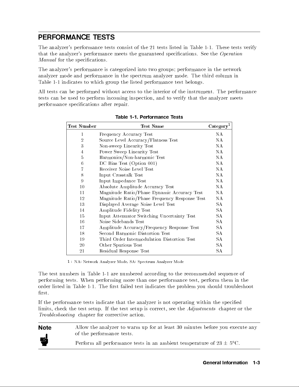
PERF
ORMANCE TESTS
The analyzer's
that
the
analyzer's
Manual
for the
The analyzer's
analyzer
T
able
All
tests
p
erformance
1-1
tests
can b
mo
de
indicates
can
e used
T
performance
p
erformance
specications.
performance
and
p
erformance
to
whic
b
e
p
erformed without
to
p
erform
sp
ecications
est
Num
b
er
1
2
3
4
5
6
7
8
9
10
11
12
13
14
15
16
17
18
19
20
21
tests
consist
meets
is categorized
in
h
group the
incoming
after
repair.
T
able 1-1.
F
requency
Source
Non-sw
P
Lev
eep
o
w
er
Sweep
of
the
the guaran
into
t
the
sp
ectrum
listed p
access to
insp
erformance test
the in
ection,
P
erformance
Test
Accuracy
el
Accuracy/Flatness
Linearit
y
T
est
Test
Linearity
21
teed sp
w
o
analyzer
Name Category
Test
Harmonics/Non-harmonic T
DC Bias
Receiver
Input Crosstalk
Input Imp
Absolute
Magnitude
Magnitude
Displa
Amplitude
Input
Noise
Amplitude
Second
Third
Other
Residual
T
est
(Option
Noise
edance
Amplitude
Ratio/Phase
Ratio/Phase
y
ed
Av
erage
Fidelit
A
tten
uator
Sidebands
Accuracy/F
Harmonic
Order
In
Spurious
Resp
onse
Lev
el
T
est
T
est
Noise
y
T
Switc
T
est
Distortion
termo
T
est
Test
001)
T
est
Accuracy
Dynamic
F
requency
Lev
est
hing
requency
dulation
tests
listed
in
T
able
1-1
. These
ecications. See
groups;
p
mo
erformance
de.
The
the
in
third
belongs.
terior of
and
to
T
v
T
ests
est
the
erify
instrumen
that
the
t.
analyzer
est NA
T
est
Accuracy
Resp
el
T
est
Uncertain
Resp
T
est
Distortion
onse
t
y
onse
T
est
T
T
est
T
est
est
T
est
Op
the
net
column
The
NA
NA
NA
NA
NA
NA
NA
NA
NA
NA
NA
SA
SA
SA
SA
SA
SA
SA
SA
SA
tests v
eration
w
ork
in
p
erformance
meets
1
erify
1
:
NA:
Net
w
ork Analyzer
The test n
performing tests. When
order listed in T
umbers in T
able 1-1 are n
performing more than one performance test, perform them in the
able 1-1. The rst failed test indicates the problem y
rst.
If the p erformance tests indicate
limits, c
Troubleshooting
Note
heck the test setup. If the test setup is correct, see the
chapter for corrective action.
Allow the analyzer to warm up for at least 30 minutes before you execute any
of the p erformance tests.
Perform all performance tests in an ambient temperature of 2365C.
Mo
de,
SA:
Sp
ectrum
Analyzer
umb
ered according to the recommended sequence of
Mo
de
ou should troubleshoot
that the analyzer is not operating within the specied
Adjustments
chapter or the
General Information 1-3
Page 30
CALIBRA
TION CYCLE
The analyzer
frequency
under
the p
CAL
The
Chapter
of
which
erformance
CULA
Calculation
4.
Calculation
Use
the
calculation
p
erformance
whic
h calculations
P
erformance
The
p
erformance
uncertain
analyzer's
ties
sp
measuremen
requires p
p
erformance
the analyzer
tests
TION
SHEET
Sheet
Sheet
sheet as
test
results.
are required
T
est
Record
test
(if
applicable).
ecications
t
uncertain
erio
dic
v
erication
is used.
con
tained
and
P
Calculation
record
are
measured
ties
are
p
erformance
Verify
in
this
AND
erformance
an
aid
for
to
obtain
lists
all test
The
measuremen
valid
only
v
erication
depends
the analyzer's
man
ual.
PERF
T
est
Record
recording
sheet
en
tries
the
test
poin
ts,
t
and
dep
when
to
remain
on the
operating
p
erformance
ORMANCE
tables
ra
w
measuremen
are
pro
vided
results.
acceptable
uncertain
ends
the
t
y
on
the
test
recommended
and en
TEST
are
pro
only
test
sho
ws
equipmen
in
calibration.
vironmental
at
RECORD
vided
t
data
for
limits,
ho
w
equipmen
least
once
in Chapter
and
calculating
p
erformance
and
measuremen
accurately
t
used.
t
is
used.
The
conditions
a
y
ear
3and
tests
the
The
listed
using
the
in
t
Ho
w
to
Use
The
follo
wing
pro
cedure
p
erformance
1. Mak
2.
F
ollo
column
provided,
3.
Calculate the
test
eextra
w
the
in
record the
record:
copies of
p
erformance
the
calculation
test
Record the test results in the T
4. When appropriate, cop
is
recommended
the
test pro
measured
result
y
when
calculation
sheet
cedure and
sheet.
using
F
or
v
alues
the
appropriate
tests
directly
est Result column in the calculation sheet.
the test results from the calculation sheet to the performance test
record.
5. Keep the performance test record for trac
periods of time.
using
and
the
record the
where
in
equation
king
gradual c
the
calculation
p
erformance
measured
no
calculation
the
p
erformance
giv
en
sheet and
test
data
sheet
test
in
the
record.
in
en
calculation sheet.
the
try
record.
the
sp
spaces are
hanges in test results o
ecied
ver long
1-4 General Information
Page 31

RECOMMENDED
Table
ma
y
T
able 1-2
1-2 lists
b
e
substituted
the
equipmen
if
.
TEST EQUIPMENT
t
required
the equipmen
T
able
for
t meets
1-2.
Recommended
p
erformance
or exceeds
testing
the critical
T
est
Equipment
the
analyzer.
specications
Other
given
equipment
in
Equipmen
Frequency
Counter
t
Frequency
2
F
requency
Standard
F
6
Sp
Net
P
P
o
o
ectrum
w
ork
w
er
Meter
w
er
Sensor
Analyzer
Analyzer
F
F
No
F
0
P
o
wer
Sensor
F
0
F
unction
Genarator
F
Accuracy:
Multimeter No
Signal
Generator
F
Phase
SSB
dBc/Hz
6
1.9
2
requency:
0
1
2
10
requency
requency
substitute
requency
26
dBm
requency
60
dBm
requency
substitute
requency
Noise
Phase
Critical
Range: 500
0
7
/y
ear
10
10
MHz,Time
10
/y
ear
Range:
Range:
Range
to
0
dBm
Range :
to
0
35
Range
6
0.2 dB,Return
Range
at
100
Noise
Specications
MHz,Time Base
Base
100
Hz
to
300
kHz
to
:
1
MHz
to
1MHz
to
dBm
:
10
Hz
to
loss:
:
1
MHz to
Hz
oset:
at
1
kHz
oset:
1.5
500
500
500
500
<
Error:
GHz
500
kHz,
>
0
Error:
MHz
MHz,P
o
w
er:
MHz,P
o
w
er:
Lev
el
20
dB
MHz,
SSB
112 dBc/Hz,
<
0
121
Recommended
Agilent
5334B
P
art
1
Model/
Num
b
Qt
er
5061B 1
8566A/B 1
8753A/B/C 1
436A
Opt.
022
,
437B,
or
438A
8482A 1
8481D 1
3325A 1
3458A 1
8663A 1
y
1
1
Signal
Generator
F
requency
Phase
SSB
Phase
Noise
Range
at
Noise
100
:
50 MHz
Hz
at
1
oset:
kHz
to 100.2
<
oset:
0
112
<
MHz, SSB
dBc/Hz,
0
121
8642B 1
dBc/Hz
Step
Atten
A
tten
uator
uator/Switc
3
h
A
tten
uation
Range
:
0
dB
to
100
dB,
dB,VSWR:
1.02
Step:
No substitute 11713A
10
8496G
Opt.
5
001
and
H60
4
Driver
50 T
ype-N Calibration
No substitute 85032B 1
Kit
T/R T
est Sets
50 MHz Lo
wP
ass Filter
Frequency Range: 300 kHz to 500 MHz,
Directivity:
Rejection at 75 MHz:
40 dB
60 dB
85044A 1
PN 0955-0306 1
50 Feedthrough Rejection at 75 MHz:60 dB PN 04192-61002 1
Termination 50 Termination, type-N(m) 909C Opt. 012 or part of
85032B
6
General Information 1-5
1
1
3
Page 32

Table
1-2. Recommended
Test
Equipment (continued)
Equipmen
6
dB
Fixed
6
dB
Fixed
10
dB
Fixed
Two-W
ay
Cables T
Adapters BNC(f
Po
A
A
tten
tten
A
w
tten
er
t
uation
uation
uation
Splitter
50
,
50
,
50
,
Frequency
T
rac
yp
e-N
BNC cable,
BNC
T
ee
BNC(m)-(f
BNC(f
N(m)-N(m)
N(m)-BNC(f
APC7.5-N(f
N(m)-N(f
N(m)-N(f
N(m)-N(f
king:
cable,
cable,
)-BNC(f
)-Dual
Critical
)
),
VSWR
),
VSWR
Range: 100
0.15
dB
50
61 cm,
122
cm,
)
adapter,
)-(f
)
Banana
adapter,
)
adapter,
)
adapter,
Specications
1.015
1.015
kHz to
500
50
50
50
adapter,
Plug
50
50
50
Adapter,
50
MHz,
50
Output
Recommended
Agilen
t
8491A
Opt.
8491A
Opt.
7
8491A
Opt.
8
11667A 1
11500B
or
part
PN 8120-1839 2
PN
8120-1840
PN
1250-0080
PN
1250-0781
PN
1251-2277
PN
1250-1475
PN
1250-0780
11524A
or
part
P
art
006
006
010
Num
&
&
of
of
11851B
85032B
Model/
b
Opt.
Opt.
Qt
er
H60
H60
9
10
y
2
2
1
4
2
1
1
1
1
2
1
1:
Option
001
(optional
2:
Required
3:
Calibration
later
4:
An
5:
Required
6:
The
7:
An
8:
An
9:
The
10:
The
Calibration Data Required for Step A
The four p erformance tests listed belo
standard (the atten
attenuators).
3. Non-Sw
11. Magnitude Ratio/Phase Dynamic Accuracy Test
14. Amplitude FidelityTest
15. Input Attenuator Switching UncertaintyTest
in
8496G
85032B
8491A
8491A
11851B
85032B
for
this
step
when
Opt.
Opt.
eep P
testing
v
alues
c
hapter.
includes
includes
includes
time
base)
an
analyzer
at
50
MHz
atten
uator
with
an
8496G
step
a
t
yp
e-N(m)
006
xed
atten
010
xed
atten
three
N(m)-N(m)
t
wo
APC7.5-N(f )
uation v
ower Linearit
alues at a frequency 50 MHz
is
equipp
are
required
required
atten
uator
uator
yT
not
uator
50
required,
with
with
est
ed
termination.
cables
adapters.
when
a
with
Option
1D5
in
the
tests.
lo
w
VSWR
(
is
used
in
the
required
required
w measure the analyzer's performance against a kno
lo
w
VSWR
lo
w
VSWR
of
61
cm
ttenuator
and a
frequency
(High
See
the
Calibr
1.02)
can
tests.
(
(
N(m)-N(m) cable
standard
Stabilit
b
e
1.015)
1.015) can
of the 8496G Opt. 001 and H60 step
in
y
F
ation
Data
purchased
can b
be
Table
requency
Re
quir
by
sp
e purc
purchased
of 88
1-2
is
Reference).
e
d
for
ecifying
hased b
b
cm.
a
v
ailable.
option
y
sp
y
sp
Step
ecifying
ecifying
A
ttenuators
H60.
Opt.
Opt.
H60.
H60.
wn
These tests require the calibrated values of the attenuators listed in Table 1-3 . The
attenuation values (referenced to 0 dB setting) are required in the calculation sheet. The
attenuation values used in the tests are listed in each calculation sheet.
1-6 General Information
Page 33

Table
1-3. Calibration
Data Required
for 8496G
Opt. 001
and
H60
The calibration
The
measuremen
only
when
the
of T
able 1-3
.
The calibration
T
ec
hnologies.
y
our
nearest
Agilen
uncertain
t
uncertain
uncertain
of step
F
or
information
t
T
t
y
ties
t
y
of
atten
ec
hnologies
F
requencyAtten
uation
50 MHz 0dB0.0037
10
dB0.0042 dB
20
dB0.0046
30
dB0.0052
40
dB0.0079
50
dB0.0125
60 dB0.0144
70
dB0.0327
80
dB0.0532
90
dB0.0543
100
dB0.0850
is
the
listed
the
step
uators,
ab
out the
primary
8496G
service
source
in
the
p
erformance
atten
uation
Opt.
calibration and
cen
ter.
of
data
001
Uncertain
t
dB
dB
dB
dB
dB
dB
dB
dB
dB
dB
measuremen
test
record
satises
and
H60,
are
the
a
v
ailable
y
t
that
error
of
giv
a
v
ailable
in
p
erformance
Chapter
en
in
the
at
uncertain
tests.
4
are
v
alid
third column
Agilen
t
ties,
con
tact
Note
The
8496G
atten
uation
segmen
these
segmen
segmen
When
dB
segmen
segment
ts.
Eac
t
that
setting
ts
in the
Opt.
segmen
h
atten
ts.
The
is
used.
the
for
tests.
001
and
ts,
10
uation
attenuations
step
atten
atten
uations
H60
programmable
dB
segmen
from
uator
from
t,
20
dB
10
dB
to
70
from 40
for
40
dB
the calibration,
dB
to
step atten
segmen
dB
is
to
70
70
dB.
Then
uator
t,
and
t
obtained
dB
dep
specify
use
has
w
o40
b
end
one of
the
y
on
four
dB
com
the
sp
bining
40
the 40
ecied
dB
General Information 1-7
Page 34

Page 35

2
Performance
INTRODUCTION
This
c
hapter
are
describ
The
test
p
erformance
mo
de
p
mode
performance
Eac
h
pro
con
ed
sequentially
name
indicates
b
elongs
erformance
cedure
consists of
tains
group.
group.
Description:
Sp
ecication:
T
est
Pro
cedure:
Note
Equipmen
t:
Allo
of
P
erform
w
the
T
ests
the
p
erformance
in the
the tested
to.
NA
SA
the
describ
describ
describ
describ
the
analyzer
p
erformance
all
p
following
performance
indicates
indicates
follo
wing
es
the
es the
es
test
es
the
to
w
tests.
erformance
test
pro
cedures.
pages.
and to
the
p
erformance
the p
erformance test
parts:
test
pro
cedure.
performance
equipmen
test
arm
tests
pro
up
t
cedure
for
in
an
The
whic
test
veried
required
step
at least
am
bien
test pro
h
b
elongs
belongs
in
in the
b
y
30
t
temp
p
the
step.
min
cedures listed
erformance
to
the
to
the
test.
test.
utes
b
efore
erature
group
net
of
work
sp
ectrum
y
ou
23
6
in T
able 1-1
the
tested
analyzer
analyzer
execute
C.
5
an
y
Note
Before
Chapter
in
the
Chapter
p
erforming
3
and
the
test
pro
CALCULATION
1.
an
the
p
cedure.
y
tests,
mak
erformance
F
or
an
explanation
SHEET AND
e
extra
copies
test
record
in
of
PERFORMANCE
of
Chapter
ho
w
to
the
calculation
4.
use
TEST
These
these
sheet in
are
required
records,
RECORD
see
in
Performance Tests 2-1
Page 36

1.
FREQUENCY A
Description
CCURACY
TEST
(NA)
This test
of
the
accuracy
Option 1D5).
Specification
F
Precision
T
est
F
F
uses a
4395A
of
the
requency
@23
@0C
Equipment
or
testing
F
requency
BNC
N(m)-BNC(f
or
testing
F
requency
F
requency
BNC
BNC
N(m)-BNC(f
C,
6
5
frequency
to
cable,
cable,
cable,
reference
RF
frequency coun
OUT
signal
internal
accuracy
referenced to
55
a
standard
Coun
an
Coun
Standard
reference
C,
referenced
ter
61
cm
:
)
adapter
4395A equipp
ter
61 cm
122
)
:
cm
adapter
ter and
when
frequency reference
C
23
accuracy
to
4395A (not
:
:
:
:
:
:
:
:
:
:
:
:
:
:
:
:
:
::
::
:
ed
:
:
:
:
:
:
:
:
::
:
:
:
:
:
:
:
:
:
:
:
:
:
:
:
:
:
:
:
:
::
::
:
:
:
:
:
23
:
::
:
:
:
:
:
:
with
:
:
:
:
:
:
:
:
:
:
:
:
it
::
C
::
:
:
:
:
:
:
:
:
a frequency
is
tuned
:
:
:
:
:
:
:
:
equipped
:
:
:
:
:
:
:
::
:
:
:
:
:
Opt.
:
:
:
:
:
:
:
:
:
:
:
:
:
:
:
:
:
:
:
:
:
:
:
::
to
(or the
:
:
:
:
:
:
(option
::
::
::
without Opt.
:
:
:
:
:
:
:
::
:
:
:
:
:
:
:
:
:
1D5
:
:
:
:
:
:
:
:
::
:
:
:
:
:
:
:
:
::
:
:
:
:
:
:
::
:
:
:
standard
100
MHz.
high stabilit
:
:
:
:
:
:
:
1D5)
:
:
:
:
:
:
:
:
:
:
:
:
:
:
:
:
:
:
:
:
:
:
:
:
:
:
::
:
:
:
:
:
:
:
:
:
:
:
:
:
:
:
:
:
:
:
:
:
:
:
:
:
:
:
:
:
:
:
:
:
:
:
::
:
:
::
:
to
measure
This
test
y
frequency
:
::
::
::
:
:
:
:
:
:
:
:
:
:
:
:
:
:
:
1D5)
:
:
:
:
::
::
:
:
:
:
:
:
:
:
:
:
:
:
:
:
:
:
:
:
:
:
:
:
:
:
::
:
:
:
:
:
:
:
:
:
:
:
:
:
:
:
:
:
:
:
:
:
:
:
:
:
:
:
::
:
:
:
:
:
:
:
:
:
:
:
:
:
:
:
:
:
::
:
:
:
:
::
the
actual
c
hecks
the frequency
reference
:
:
:
:
:
:
:
:
:
:
:
:
::
::
::
:
:
:
:
:
:
:
:
:
:
:
:
:
:
::
:
:
:
:
:
:
:
:
:
:
:
:
:
:
:
:
:
:
:
:
:
:
:
:
:
:
:
:
::
:
:
:
:
:
:
:
:
:
:
:
:
::
:
:
:
:
:
:
:
:
:
:
:
:
:
::
:
:
:
:
:
:
:
frequency
for
:
:
:
:
:<
6
:
:
:
:
<
6
0.13
:
:
:
:
:
:
:
:
::
:
:
:
PN
8120-1839
:
::
PN 1250-0780
:
:
:
:
:
:
::
:
:
:
:
:
:
:
:
:
:
:
:
:
PN
8120-1839
:
:
:
PN 8120-1840
:
:
:
PN
1250-0780
5.5
ppm
ppm
:
5334B
:
:
5334B
5061B
1
1:
The
5061B
can
b
e replaced
Procedure
1.
Connect the
For testing a standard 4395A (not equipped with Option 1D5), do not connect an
to the EXT REF Input connector in the 4395A rear panel.
For testing
bet
ween the EXT REF Input connector and the REF O
rear panel.
2-2 Performance Tests
test equipmen
an 4395A equipped with Option 1D5, connect a BNC(m)-BNC(m) cable
with an
tas
y10
MHz frequency
sho
wn
in
Figure
standard
2-1
.
with
time
base
error
of
<
VEN connector on the 4395A
0
10
/y
6
1
x
10
ear.
y cable
Page 37

2.
Initialize the
Con
Gate
INT/EXT
3.
Press
the con
Con
Center F
Frequency Span: ZER
4
Meas
trols
frequency coun
trols
Time
Switch
N
N
N
N
N
N
NN
NN
NN
NN
N
N
N
N
N
N
N
follo
N
ws:
ANALYZER TYPE
5
,
as
trol
Settings
requency: 100 MHz
(rear
N
N
N
N
N
N
N
Figure
ter.
panel)
N
N
NN
NN
NN
NN
N
N
O
2-1.
Frequency
Then
set
the
Settings
1
sec.
External(When
N
N
N
N
N
N
NN
NN
NN
NN
N
N
N
N
N
N
N
N
N
N
N
N
N
N
N
N
N
NN
NN
Center
Span
NN
Strok
5,4
NNNNNNN
ZERO SPAN
5
,
NETWORK ANALYZER
,
Key
4
4
Accuracy
frequency
NN
N
N
N
N
N
N
N
N
N
N
N
,
4
es
5,4
5,4
0
0
1
NNNNNNNNNNNNNNNNNNNNNN
the
Preset
5,4
M/
T
est
Setup
standard
frequency
5
to
initialize
5
is
connected)
standard
the
is
4395A
connected).
.
Then
set
The source p o
4.
Press
4
Trigger
wer no
NNNNN
SINGLE
5
,
wissetto
NNNNNNNNNNNNNNN
to mak
5. Record the frequency coun
(\Test Result" column).
0 dBm (preset v
easw
eep. W
alue).
ait for the frequency coun
ter reading to settle.
ter reading to 1 Hz resolution in the p erformance test record
Performance Tests 2-3
Page 38

2.
SOURCE LEVEL
Description
ACCURA
CY/FLA
TNESS
TEST
(NA)
This test
OUT
0
dBm.
as p
Specification
Level
Flatness
T
est
P
P
Multimeter
50
BNC
N(m)-BNC(f
BNC(f
Procedure
uses a
signal
o
w
@23
@23
Equipment
o
w
o
w
at
The
er
deviation
accuracy
C,
6
5
6
C, relativ
5
er
Meter
er
Sensor
F
eedthrough
cable,
)-Dual
level
po
wer
sev
eral
accuracy is
from
50
MHz,
:
::
::
:
:
:
:
:
:
:
:
:
:
61
cm
)
adapter
Banana
meter and
frequencies
the
p
0
dBm
e
to
50
::
:
:
:
:
:
:
:
:
:
:
::
::
:
:
:
:
:
:
:
:
::
::
:
:
:
:
:
:
:
:
:
:
:
:
:
:
:
:
Plug Adapter
chec
o
w
MHz,
:
:
:
::
::
:
:
:
:
:
:
:
:
::
:
:
:
a
p
o
from
ked
er
reading
output
0
:
:
:
:
:
:
:
:
:
:
:
:
:
::
:
:
:
:
:
:
:
:
:
:
:
:
:
:
:
w
er
10
at
dBm
:
:
:
:
:
::
:
:
:
:
:
:
:
:
:
:
:
sensor
Hz
a
frequency
tak
:
:
:
:
:
output
:
:
::
::
:
:
:
:
:
:
:
:
:
:
:
:
:
:
:
:
:
:
:
:
:
::
:
:
:
:
:
:
to
measure
to
500
MHz
50
en
at
50
:
:
:
::
::
::
:
:
:
:
:
::
:
:
:
:
:
:
:
:
:
:
:
::
::
::
:
:
:
:
:
:
:
:
:
:
:
::
::
:
:
:
:
:
:
:
:
:
:
:
:
:
:
:
:
:
:
:
:
:
:
:
:
:
:
:
:
:
:
:
:
:
MHz.
MHz.
:
:
:
:
:
:
:
:
:
::
:
:
:
:
:
:
:
::
:
:
:
:
:
:
when
:
:
:
:
:
:
:
:
:
:
:
:
:
:
:
:
:
:
:
:
:
:
:
:
:
the
:
:
:
:
::
:
:
:
:
:
:
:
:
:
:
:
:
:
::
actual
the
The
:
:
::
:
436A
:
:
::
:
:
:
:
:
:
:
:
:
:
::
:
:
:
:
:
::
:
:
:
:
:
:
:
:
:
:
signal
lev
:
:
:
:
:
Opt.
:
:
:
:
:
:
:
:
:
:
:
::
:
:
:
:
p
ow
el
atness
:
:
:
::
:
:
:
:
:
:
:
:
:
:
:
::
:
:
:
:
:
:
:
:
:
::
:
:
:
er lev
el of
amplitude
is
::
::
:
:
:
:
:
:
:
:
:
:
:
022
,
437B, or
:
::
::
::
::
:
:
:
:
:
:
:
:
:
:
:
PN
:
:
:
:
:
:
PN 8120-1839
:
:
:
:
:
:
PN
:
:
:
:
:
:
PN
the RF
is set
to
calculated
:
:
<
6
1.0
dB
:
:
:
:
6
2.0
dB
438A
:
:
:
:
:
8482A
:
:
:
:
::
3458A
04192-61002
1250-0780
1251-2277
1.
Connect the
sensor.
2.
Connect
the
p
o
test
w
er
sensor
equipmen
to
the
p
o
w
er
meter.
t
as
sho
wn
in
Figure
Calibrate
2-2.
the
p
o
w
er
meter
for
the
po
wer
2-4 Performance Tests
Page 39

N
N
NN
NN
N
N
N
N
N
N
N
N
N
N
N
N
N
N
N
N
N
3.
Press
the
The
4.
Source
a. W
b.
5.
Source
a.
b. Press
5
4
,
Meas
con
trols
Con
trol
Cen
ter
F
F
requency
source
ait
Record
for
Lev
the
Lev
for
p
el
the
the
lev
el
Record the
Reading
4
Center
[ref
ANALYZER
as
follo
Settings
requency:
Span:
o
w
er
Accuracy
po
el
accuracy
Flatness
test
]"
5,4
N
ws:
0
no
wis
p
o
w
er
wer
meter reading
result
column
5,4
M/
1
test frequency 1 MHz listed in T
frequencies.
Figure
N
N
N
NN
NN
N
N
N
TYPE
50
Hz
set to
T
est
meter
test).
T
est
of
for
5
N
N
N
N
N
N
N
,
MHz
reading
(High
the
the
to c
2-2.
Source
N
N
NN
NN
N
N
N
N
N
N
N
N
N
N
N
N
N
N
NETWORK
Key
4
Center
4
Span
0
dBm
to
in
F
requencies)
lev
el
accuracy
lev
el
atness test).
hange the
able 2-1
Lev
N
N
N
N
N
N
N
NN
NN
N
N
N
N
N
N
ANALYZER
Strok
5
,
N
N
N
5
,
(preset
settle.
the
p
erformance
4395A cen
.T
el
Accuracy
N
N
N
N
N
N
N
N
N
N
N
N
N
,
4
Preset
T
est
5
to
Setup
initialize
the
es
5
,
4
5
N
N
NN
N
N
N
ZERO
v
alue).
test
5
4
0
N
N
N
N
N
N
N
N
in
,
4
M/
N
N
N
N
N
N
N
SPAN
the
N
5
N
N
N
N
NN
N
N
N
test
record
calculation
(\T
est
sheet (\P
ter frequency to the rst atness
able 2-1 lists atness test poin
4395A
Result"
ow
ts for
.
Then
column
er Meter
high
set
Performance Tests 2-5
Page 40

c. W
sheet
d.
Change
each
e.
Calculate
results
ait for
(\P
frequency
the p
the
in
o
test
the
w
er
4395A
Table
ow
er
meter
Meter
Reading"
cen
.
results
p
erformance
using
2-1. Source
reading
ter
frequency
the
test
Cen
to
settle.
column).
in
equation
record.
Level
Flatness T
4395A
ter
F
requency
1MHz
3
10
45
75
110
140
190
235
290
345
400
445
470
500
Then
accordance
given
in
MHz
MHz
MHz
MHz
MHz
MHz
MHz
MHz
MHz
MHz
MHz
MHz
MHz
MHz
record
with
the
est Settings
the
reading
T
able
2-1
calculation
1
and
sheet.
in
rep
the
calculation
eat
Record
step 5-c
the
for
test
6.
Source
a.
Connect
Lev
el
Flatness
the
test
T
est
(Lo
w
F
requencies)
equipmen
tas
sho
wn
in
Figure
2-3
.
Figure 2-3. Source Level Flatness Test Setup
2-6 Performance Tests
Page 41

b.
Initialize the
Controls
Measuremen
Displa
Measurement
NPLC
c.
Press
test
frequency
frequencies.
4
Center
multimeter.
t
F
y Reading
Metho
5
5
5
,
4
,
4
1
0
10
Hz
unction
Value
d
5
,
4
to c
x1
listed
T
able
Then set
hange the
in
T
able
2-2.
Source
the con
trols as
Settings
A
C
Volts
dBm Reading
Syncronous
100
4395A cen
2-2
.
T
able
Lev
el
Flatness
4395A
Cen
ter F
requency
160
500
2-2
10
50
500
2
12
60
Mode
kHz
kHz
kHz
kHz
kHz
follows:
Value
Sampling
ter
frequency
lists
atness
T
est
Hz
Hz
Hz
Con
v
ersion
to
the
test p
Settings 2
rst
oints
atness
for lo
w
d.
W
sheet
e.
Change
eac
f.
Calculate
results in
ait
for
(\P
h
frequency
the
o
w
er
the
4395A cen
test
the p
m
ultimeter
Meter
.
results
erformance
reading
Reading"
ter
frequency
using
the
test
to
settle.
column).
in
equation
record.
Then
accordance
giv
en
in
record
with
the
the
reading in
T
able
2-2
calculation
and
sheet.
the
calculation
rep
eat
Record
step
the
6-d
for
test
Performance Tests 2-7
Page 42

3.
NON-SWEEP PO
Description
WER LINEARITY
TEST
(NA)
This test
of
the
The
In
this
dBm
sensor's
adding the
calibrated
Specification
Lev
T
est Equipment
P
P
T
Step
A
4395A
p
o
wer
test, the
using
non-linearit
el
linearity
o
w
er
o
w
er
yp
e-N
A
tten
uator
uses a
RF
linearity
the
attenuation
atten
1
:
@23
Meter
Sensor
Cable,
tten
uator
driv
po
wer
OUT
is referenced
input p
step
atten
y
uation
C,
6
5
:
:
:
:
:
:
:
:
:
:
61
cm
1
,
10
er
:
meter and
signal
ow
er to
uator.
and
noise.
used and
v
alues
relativ
e
:
:
:
:
:
:
::
:
:
:
:
:
:
:
::
:
:
dB
Step,
:
:
:
:
:
:
:
at
of
to
:
:
:
:
:
:
:
a
sev
to a
the
This
The
the p
the
Output
0
40
p
o
w
er
0
dBm
:
:
:
:
:
:
:
:
:
:
:
:
VSWR
:
:
:
:
high
eral
p
step
dBm
<
output
:
:
:
::
:
:
:
::
:
sensitivit
p
o
p
o
w
o
w
er
reduces
actual
o
w
er
atten
P
o
w
p
o
0
40
dBm
:
:
:
:
:
:
:
:
:
:
:
:
:
:
::
:
:
w
er
settings
er
lev
el
sensor
measuremen
p
o
wer
meter
uator
er
w
er
:
:
:
:
:
:
:
:
:
:
:
:
:
:
:
:
:
:
:
:
1.02
:
:
:
:
:
:
:
y
p
o
of
0
is
main
of the
reading.
at
:
:
:
:
::
:
:
:
:
:
:
::
:
:
:
:
:
:
:
:
:
:
:
:
w
er
and
dBm.
tained
RF OUT
50
:
:
:
:
:
:
:
:
:
:
:
:
:
::
::
:
:
:
:
sensor
t
MHz.
:
:
:
to
then
calculates the
b
et
uncertain
Therefore,
:
:
:
:
:
436A
:
:
::
:
:
:
:
:
:
:
:
:
:
:
:
:
:
:
:
:
:
::
::
measure
w
een
t
signal is
:
:
:
:
:
:
:
:
11500B
:
:
:
8496G
:
:
:
:
:
0
y
caused
this
Linearit
6
6
Opt.
:
:
:
:
:
:
:
:
the actual
po
60
dBm
b
calculated
test
requires
1
y
1.0
dB
1.5
dB
022
,
:
:
:
:
:
:
or
part
Opt.
:
:
:
:
:
:
wer
and
y
the
437B,
:
:
:
:
001
:
:
:
:
po
linearity
0
30
p
ow
b
y
the
or
438A
:
:
::
8481D
of
11851B
and
:
:
:
11713A
wer
.
er
H60
1:
Calibration v
Procedure
1. Record
(\Calibration
2. Connect the po
po
3. Set the step atten
po
4. Connect the test
2-8 Performance Tests
the step
wer sensor.
wer sensor from excess input.
attenuator
V
alue" column).
wer sensor to the po
uator to 30 dB before connecting the test equipmen
equipment as sho
alues for
attenuation
50 MHz
settings
wer meter, and calibrate the p
wn in Figure 2-4
of
10
dB
calibration v
to
50
alues
.
dB
in
at
50
the
MHz
calculation
are
required.
sheet
ower meter for the
t. This protects the
Page 43

5.
6.
7.
8.
Press
set
the
Con
Cen
F
requency
The
source
Set
the
W
ait
Record
column
4
for
Meas
5
con
trols
trol
ter
step
the
the
of the
Figure
N
N
N
N
N
N
N
N
N
N
N
N
N
N
N
N
N
N
NN
NN
N
N
N
N
ANALYZER
,
as follo
N
ws:
Settings
F
requency:
p
o
atten
p
p
o
Span:
w
o
w
w
er
no
uator to
er
meter
er
meter
0Hz
w
is
calculation sheet
T
able
2-4.
N
N
N
N
N
N
N
N
N
N
N
N
N
N
TYPE
,
50
MHz
set
to
the rst
reading to
reading
2-3.
Non-sweep
N
N
N
N
N
N
N
N
N
N
N
N
N
N
N
N
N
N
NN
NETWORK
Key
4
4
0
dBm
setting
settle.
in
the
for the
Non-Sw
eep
Po
wer
NN
N
N
N
N
N
N
N
N
N
N
N
N
N
N
N
N
N
N
ANALYZER
Strok
5
,
5
,
4
5
N
N
N
N
N
N
ZERO
Center
Span
(preset
30
dB
calculation
reference
P
o
wer
Linearity T
N
N
N
NN
NN
N
N
N
,
4
Preset
es
5
5
,
,
4
0
N
N
N
N
N
N
N
N
N
N
N
N
N
N
N
NN
SPAN
v
alue).
listed
sheet.
0
dBm.
Linearity T
4
M/
N
N
N
N
N
N
in
est
Setup
5
to
initialize
5
the
second
Use
\P
o
est Settings
w
er
the
column
Meter
4395A
of
T
Reading"
.
Then
able
2-3
.
ower
Step
A
4395A
Source P
0 dBm 30 dB
+15 dBm 50 dB
+10 dBm 40 dB
0
10 dBm 20 dB
0
20 dBm 10 dB
0
30 dBm 10 dB
0
40 dBm 10 dB
0
50 dBm 10 dB
tten
uator
Performance Tests 2-9
Page 44

9.
Change
Record
column of
10.
Rep
11.
Calculate the
test
the
the p
eat
step
results
source
ow
er meter
p
o
w
er
the calculation
9
for
eac
h
setting.
test results
in
the
p
erformance
and
the
reading in
sheet for
using
the
test
step atten
uator setting
the calculation
the
non-sw
equations
giv
record.
eep
en
in accordance
sheet. Use
p
o
w
er
linearit
in
the
\Po
w
y
test.
calculation
er
with T
Meter
sheet.
able 2-3
Reading"
Record
.
the
2-10 Performance Tests
Page 45

4.
POWER
Description
SWEEP LINEARITY
TEST
(NA)
This test
dBm
sensitivit
is measured.
p
o
w
This
reduces the
p
o
w
meter
Specification
Sw
Sw
T
est
P
P
Step
A
T
sets the
to
0
30
y
p
ow
er
linearit
test
uses
measurement
er
of
the
reading.
eep
range
eep linearit
@23
o
w
o
w
tten
yp
C,
6
5
Equipment
er
Meter
er
Sensor
A
tten
uator driv
e-N
Cable,
dBm
Then
RF
uator,
4395A to
and
er sensor,
the
y
is
sp
ecied
a
step
OUT
:
:
:
:
y
50
MHz,
:
:
:
:
:
:
:
:
:
10
er
61
0
p
atten
signal
:
:
:
:
:
:
:
:
:
::
dB
:
:
:
:
cm
o
relativ
:
:
:
the p
ow
5
dBm
to
the actual
w
er
sw
eep
as
values
uator
to
uncertaint
is
calculated
:
:
:
:
:
:
:
:
::
eto
:
:
:
:
:
:
:
:
:
:
:
:
:
:
:
:
Step
,
VSWR
:
:
:
:
:
:
:
:
:
:
:
::
:
:
:
:
er
15
po
linearit
relative
main
y caused
:
:
:
stop p
:
:
:
:
:
:
:
:
:
:
:
:
:
:
:
:
:
sw
eep
dBm
w
er
tain the
:
:
:
:
:
:
::
:
:
:
:
:
:
:
:
:
:
:
:
of
b
:
ow
:
:
:
:
:
:
::
mo
in
the
y
for
to the
b
y
adding
:
:
:
er
:
:
:
:
:
1.02
:
:
:
:
5
y
:
:
:
:
:
:
:
:
:
:
de
and
dB
4395A
a
sw
stop p
po
wer
the
:
:
:
:
:
:
:
:
:
:
::
:
:
:
:
:
:
:
:
:
:
:
:
:
:
then
steps.
:
:
:
:
:
Using a
RF
eep
span
o
w
sensor input
p
o
w
er
the
atten
:
:
:
:
:
:
::
:
:
:
:
:
:
:
:
:
:
:
:
:
:
:
:
:
:
:
:
:
:
:
::
:
:
:
:
:
:
:
::
:
:
:
:
mak
OUT
er.
sensor's
uation
:
:
:
:
:
:
:
:
:
:
:
:
:
:
:
436A
:
:
:
:
:
:
:
:
:
:
:
:
:
:
:
:
:
:
:
:
:
:
:
:
es
a
po
signal
+20
linearit
:
:
:
:
::
::
:
:
:
:
:
:
:
:
:
:
:
:
p
ow
wer
at
dB is
lev
el
used
:
:
:
:
:
::
::
Opt.
:
:
:
:
:
:
8496G
::
:
:
:
:
11500B
er sw
eep from
meter and
eac
h
calculated. The
0
35
y
error.
and the
:
:
:
:
:
:
:
:
:
022,
::
:
:
:
Opt.
:
:
:
:
:
or
:
:
:
:
:
:
:
:
part
sw
eep
dBm.
The
po
:
:
:
:
:
:
:
437B,
:
:
:
:
001
:
:
:
:
a
::
:
:
:
0
high
p
oin
This
actual
wer
:
:
:
:
6
0.5
or
:
:
:
and
:
:
11713A
of
11851B
50
t
20
dB
dB
438A
8481D
H60
Procedure
1.
Connect
p
o
w
er
2. Set
3.
the
p
ow
er sensor
Connect
the
sensor.
step
the
po
wer
sensor to
atten
uator
from excess
test
equipmen
to
input.
the p
30
tas
dB
sho
o
b
efore
wn
w
er
in
meter.
Then
connecting
Figure
2-5
calibrate
the
test
.
the
p
o
equipmen
w
er
t.
meter
This
for
the
protects
the
Performance Tests 2-11
Page 46

4.
Press
set
the
Con
P
o
CW
Start
Stop
Num
Trigger:
T
rigger
5.
Press
the 4395A po
test
settings. V
4
Meas
con
w
4
T
rigger
trol
er
F
P
b
Figure
N
N
N
N
N
N
N
N
N
N
N
N
N
N
N
N
N
N
NN
NN
N
N
N
N
N
N
N
N
N
N
N
N
N
ANALYZER
5
,
trols
as follo
Settings
Sw
eep
requency:
P
o
w
er:
0
50
o
w
er:
0
30
er
of
P
oin
ts:
Manual
Ev
en
t:On
N
N
N
N
N
N
N
N
NN
NN
NN
NN
SINGLE
5
,
wer to the rst sw
erify that the step atten
N
TYPE
ws:
50
MHz
dBm
dBm
5
P
oin
t
N
N
N
N
N
N
N
N
NN
NN
NN
TRIGGER:[MANUAL]
,
2-5.
N
N
N
N
N
,
NN
NN
NN
NN
Po
wer
N
N
N
N
N
N
N
N
N
N
N
N
N
N
N
N
NETWORK
NN
NN
N
N
N
N
N
N
N
N
N
N
N
NN
eep p
ointof050 dBm listed in T
Sweep
N
N
NN
NN
N
N
N
N
N
N
N
ANALYZER
Key
4
Sw
eep
4
Source
4
Sta
rt
5
4
Stop
4
Sw
eep
4
T
rigger
4
T
rigger
(Then
N
N
N
N
N
N
N
N
N
N
N
TRIGGER
NN
NN
NN
NN
NN
NN
uator is set to 10 dB.
Linearity T
N
N
N
N
N
N
N
N
N
N
N
N
N
N
NN
NN
N
N
N
Strok
es
N
N
N
N
N
N
NN
N
N
N
N
N
SWEEP
5
,
N
N
N
N
N
N
N
N
N
N
N
N
CW
FREQ
5
,
5
5
,
,
5
N
N
N
N
N
5
,
,
4
4
-
5
5
5
,
,
4
4
-
3
N
N
N
N
N
N
N
N
N
N
N
N
N
NUMBER
,
N
N
N
N
N
NN
NN
NN
NN
TRIGGER[xxx]
5
,
N
NN
NN
N
N
N
N
N
N
N
TRIGGER[xxx]
5
,
the
softk
N
N
N
N
NN
NN
NN
NN
N
N
N
N
N
N
[ON
N
N
N
N
N
N
N
N
NN
NN
MANUAL
,
NN
N
,
4
Preset
N
N
N
N
N
N
N
N
N
TYPE
N
N
N
N
N
N
N
N
N
5
4
0
5
,
4
0
N
N
NN
NN
N
N
N
of
N
N
N
N
N
N
N
N
N
N
N
N
N
N
N
N
N
ey
N
N
N
N
N
N
N
N
N
POINT]
NN
NN
NN
to
N
N
,
N
N
N
N
N
N
N
,
4
4
x1
4
x1
N
N
N
N
N
N
N
N
N
N
N
N
N
N
NN
NN
lab
N
N
NN
NN
est
5
to
N
N
N
NN
N
N
N
N
N
N
MENU
5
,
4
0
5
5
5
N
N
N
N
N
N
N
N
N
N
N
POINTS
N
N
N
NN
NN
NN
NN
NN
N
N
N
N
N
N
N
el
NN
NN
N
N
N
N
N
start
Setup
initialize
N
N
N
N
N
N
N
N
N
N
N
N
POWER
,
5
,
4
M/
N
NN
NN
N
N
N
N
N
N
,
4
N
N
N
N
N
NN
NN
NN
MANUAL
,
N
NN
NN
N
N
N
N
N
N
N
TRIG
,
c
hanges
a
p
o
w
able 2-4. T
N
N
NN
N
N
N
5
5
,
5
NN
N
N
N
N
N
N
N
N
N
N
N
N
EVENT
er
the
N
N
N
N
N
N
N
N
N
SWEEP
5
4
x1
N
N
N
N
N
N
N
N
NN
NN
to
sweep
4395A
N
N
N
N
NN
N
N
.
Then
N
N
N
N
N
N
N
NN
N
N
N
N
N
N
N
N
N
N
N
N
N
N
N
N
N
N
N
NN
NN
NN
N
[ON
and
able 2-4 lists
N
SWEEP]
to
set
N
N
N
N
N
N
N
N
2-12 Performance Tests
Table 2-4. P
Source P
ow
er Sw
eep Linearity T
ower
Step A
ttenuator
4395A
0
50 dBm 10 dB
0
45 dBm 10 dB
0
40 dBm 10 dB
0
35 dBm 10 dB
0
30 dBm 10 dB
est Settings 1
Page 47
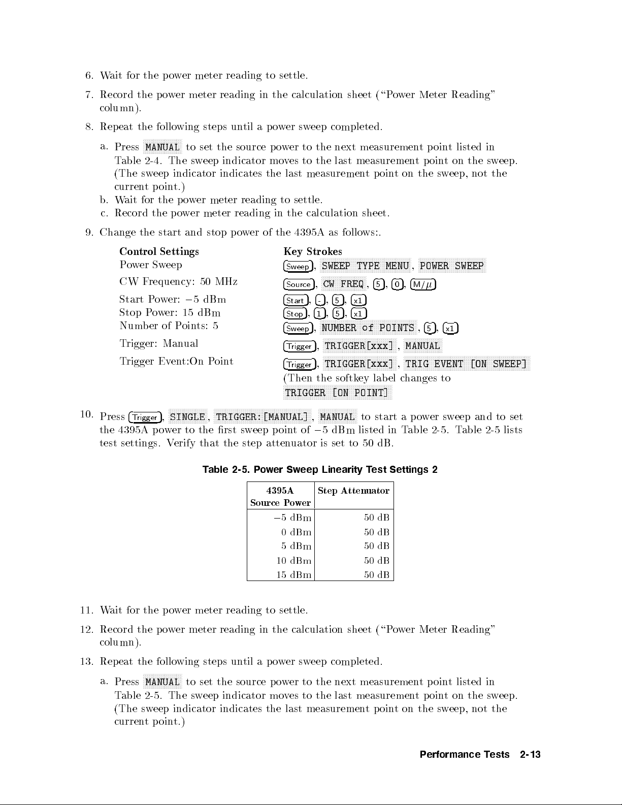
6.
W
7.
Record the
column).
8.
Rep
a.
b.
c.
9.
Change
10.
Press
the
test
ait
for
the
eat
the
NN
N
N
Press
T
(The
curren
W
Record the
MANUAL
able
2-4
sweep
t
ait
for
the
Con
trol
P
ow
er Sw
CW
F
requency:
Start
P
Stop
P
Num
b
T
rigger:
T
rigger
4
T
rigger
4395A
settings.
er
p
o
w
er
meter
po
wer
meter reading
following
N
N
N
N
N
N
N
N
N
NN
.
The
p
oin
the
po
start
Settings
eep
o
w
er:
o
w
er:
of
Man
Ev
en
N
N
N
SINGLE
5
,
p
o
w
er
V
steps un
NN
NN
N
to
set
sw
eep
indicator indicates
t.)
p
o
w
er meter
wer
meter
and
stop
50 MHz
0
5
dBm
15
dBm
P
oin
ts:
ual
t:On
P
N
N
N
N
N
N
N
NN
N
N
N
N
N
N
N
N
,
to
the
erify that
reading to
til a
the
source
indicator
reading to
reading
p
o
w
5
oin
t
N
N
N
N
N
N
N
N
N
N
NN
N
N
N
N
N
rst
sw
the step
N
TRIGGER:[MANUAL]
er
N
N
N
eep
N
N
N
in the
N
settle.
calculation sheet
po
wer
p
o
w
er
mo
v
es to
the last
settle.
in
the
of
the
4395A
Key
4
Sw
4
Source
4
Sta
4
Stop
4
Sw
4
T
rigger
4
T
rigger
(Then
N
N
N
N
N
N
N
TRIGGER
N
N
N
N
N
N
N
N
N
N
NN
N
N
N
N
N
p
oin
t
atten
uator
sweep
eep
rt
eep
N
N
N
N
N
completed.
to
the
next measuremen
the last
measurement
calculation
as
Strok
es
N
N
N
N
N
N
N
N
N
N
N
N
SWEEP
5
,
N
N
N
N
N
N
N
N
N
N
N
CW
FREQ
,
5
,
5
4
4
-
5
5
5
,
4
4
5
1
N
N
N
N
N
N
N
N
N
NN
NN
NUMBER
,
N
N
N
NN
NN
N
N
N
TRIGGER[xxx]
5
,
N
N
N
N
N
N
N
N
N
N
TRIGGER[xxx]
5
,
the
softk
N
N
NN
N
N
N
N
N
N
N
N
N
N
N
N
N
[ON
N
N
N
N
N
N
N
N
N
N
NN
N
MANUAL
,
0
5
dBm
is
set
N
of
5
5
,
5
,
5
N
N
N
N
N
N
N
N
N
(\Po
measurement
p
oin
sheet.
follo
ws:.
N
N
N
N
N
NN
NN
NN
N
N
N
N
N
N
N
N
N
N
N
TYPE
N
N
N
N
NN
NN
N
N
N
N
5
,
,
4
5
,
5
4
x1
5
,
4
x1
NN
NN
N
N
N
N
N
N
N
N
N
N
N
N
N
N
N
N
N
of POINTS
N
N
N
N
N
N
N
N
N
N
N
N
N
N
N
N
N
N
NN
NN
N
N
N
N
N
N
N
N
N
N
NN
NN
N
N
N
N
N
N
N
N
ey
lab
N
N
N
N
N
N
N
N
N
N
NN
N
N
N
N
N
N
N
N
N
N
to
listed
50
N
start
dB.
POINT]
N
N
N
N
N
N
to
w
t
on
N
N
N
N
N
N
N
N
NN
NN
MENU
5
,
4
0
NN
NN
NN
NN
N
N
N
N
N
N
N
N
N
N
MANUAL
,
N
N
N
N
N
N
N
TRIG
,
el
c
hanges to
N
N
N
a
in
T
er
Meter
tp
oint
poin
the
N
N
N
N
N
N
N
N
N
N
POWER
,
5
4
M/
N
N
N
N
N
5
,
4
5
N
N
NN
NN
N
N
N
N
N
N
N
N
N
N
N
N
N
N
N
N
N
N
N
N
N
N
N
N
N
N
EVENT
p
o
w
er
able 2-5
Reading"
listed in
t
on
sw
eep,
N
N
N
N
N
N
N
N
NN
NN
SWEEP
5
,
4
x1
N
N
N
N
N
N
NN
NN
N
N
N
N
sw
eep
.
T
NN
N
N
N
N
N
N
N
able
the
not
N
N
N
N
N
N
N
N
[ON
N
N
N
N
N
N
N
N
N
N
and
sw
eep.
the
N
N
N
N
NN
NN
N
N
SWEEP]
to
2-5
N
N
N
N
N
N
set
lists
N
N
N
N
N
N
N
N
T
able
2-5.
P
o
w
er
Sw
eep
Linearity
w
er
dBm
dBm
dBm
Step
4395A
Source
11. Wait for the po
12. Record the po
column).
13. Repeat the following steps until a p ower sweep completed.
a.
NNNNNNNNNNNNNNNNNNNN
Press
Table 2-5. The sweep indicator moves to the last measurementpointonthesweep.
(The sweep indicator indicates the last measurementpoint on the sweep, not the
currentpoint.)
wer meter reading to settle.
wer meter reading in the calculation sheet
MANUAL
to set the source power to the next measurement point listed in
Po
0
5
0
5
10 dBm 50 dB
15 dBm 50 dB
Atten
T
est
uator
50
50
50
Settings
dB
dB
dB
(\Power Meter Reading"
2
Performance Tests 2-13
Page 48

b.
c.
W
ait
Record
for
the
the
po
p
o
w
er
meter
wer
meter reading
reading
to
in the
settle.
calculation sheet.
14. Calculate
test
results
the test
in
the
results using
p
erformance
the equation
test
record.
giv
en
in
the
calculation
sheet.
Record
the
2-14 Performance Tests
Page 49

5.
HARMONICS/NON-HARMONIC SPURIOUS
Description
TEST (NA)
This test
measure
The
are most
RF
sets the
the
RF
OUT
OUT
signal frequency
lik
ely
to
4395A RF
Specification
Spectral
Purity
Harmonics
@+10
dBm
Non-harmonics spurious
@+10
T
est Equipment
Sp
ectrum
T
yp
e-N
BNC
Cable,
cable,
dBm
Analyzer
61
122
Procedure
1.
Connect
the
test
OUT signal
signal's
second,third
is set
b
e
observ
ed.
Characteristics
output
output
cm
equipmen
cm
:
::
:
:
::
::
:
:
:
:
:
:
:
:
:
:
:
:
:
:
:
:
:
:
:
:
::
:
:
:
:
:
t
as
po
w
er
to
+10
dBm
and
uses
a
sp
ectrum
and
non
harmonic
to v
alues where
::
:
:
:
:
:
:
:
:
:
:
:
:
:
:
:
:
:
:
::
::
:
:
:
:
:
:
::
::
::
::
:
:
:
:
:
:
:
:
:
:
:
:
:
:
:
::
::
:
:
:
:
:
:
:
:
:
:
:
:
:
:
:
:
:
sho
wn
in
Figure
:
:
:
:
:
:
:
:
:
:
:
:
:
::
harmonics
:
:
:
:
::
:
:
:
:
:
:
:
:
:
:
:
:
:
:
:
:
:
:
::
:
:
:
2-6.
:
::
:
:
:
:
:
:
::
:
:
::
:
:
:
spurious
:
:
:
:
:
:
:
::
::
:
:
:
:
:
:
:
:
and
non-harmonic
:
:
:
:
:
:
:
::
::
:
:
:
::
:
:
:
:
:
:
:
::
:
11500B
:
:
:
:
:
:
:
at
sev
:
:
:
:
:
:
:
:
:
:
:
:
:
:
:
:
:
:
:
:
:
::
::
eral
:
:
:
:
:
or
:
:
:
::
:
:
:
:
:
:
:
part
:
analyzer
frequencies.
spurious
::
:<
0
30
:
:
:
<
0
30
:
:
::
8566A/B
of
11851B
PN
8120-1840
to
dBc
dBc
Figure 2-6. Harmonics Test Setup
Performance Tests 2-15
Page 50

Note
Connect
4395A
conguration, b
the
EXT
same
the sp
REF
reference
ectrum analyzer's
Input
oth the
on
spectrum
frequency
the rear
to
10 MHz
panel as
analyzer and
eliminate
frequency
shown
the 4395A
frequency
reference
in Figure
are
oset
errors.
output
2-6.
With this
phase
lo
to
the
c
k
ed
to
2. Initialize
with
the
3.
On the
Con
Reference
4.
Press
4
Meas
the con
Con
F
requency
Source
5.
|Harmonics
a.
On
the
frequency
the
sp
sp
ectrum
spectrum
trols
N
N
N
N
ANALYZER
5
,
trols as
trol
Settings
P
o
w
T
4395A
listed in
ectrum
analyzer
analyzer, set
Lev
el
N
N
N
NN
NN
NN
N
N
N
N
N
N
N
N
N
N
follows:
Span:
est|
er:
,
Cen
0
+10
press
4395A
ter
analyzer,
man
N
N
N
N
N
N
N
N
N
NN
NN
NN
N
TYPE
Hz
dBm
4
Center
the rst
F
requency
10
500
10
MHz
100
MHz
250
MHz
500
MHz
the con
N
N
N
N
N
N
NETWORK
,
5
,
4
column
T
able
kHz
kHz
and
ual.
N
N
N
NN
NN
5
1
2nd
NN
,
p
erform
trols
Settings
+10
N
N
N
N
N
N
N
N
N
N
N
N
N
N
N
N
ANALYZER
Key
4
Span
4
Source
5
,
4
4
0
k/m
of
T
2-6.
Harmonics
Harmonics
F
requency
20
1
20
200
500
1.0
as
dBm
N
N
N
NN
NN
NN
Strok
N
N
NN
ZERO
5
,
5
,
5
to
able
kHz
MHz
MHz
MHz
MHz
GHz
the
follo
N
N
N
N
N
N
N
N
N
N
es
NN
N
N
N
N
N
N
N
N
N
N
NN
N
N
N
N
N
POWER
set
2-6
Sp
3rd
FREQ
ws:
N
N
,
N
N
N
N
SPAN
N
N
N
N
.
ectrum
F
ZER
O
calibration
5
N
N
N
N
4
able
est
1.5
300
750
N
N
NN
5
1
cen
30
1.5
,
30
to initialize
5
5
,
4
4
x1
0
ter
frequency
2-6
lists
Settings
Analyzer
kHz
MHz
MHz
MHz
MHz
GHz
Span
4
Preset
N
N
N
N
N
N
N
,
the
T
T
HarmonicsFrequency
requency
the 4395A
test
frequencies.
1
kHz
1
kHz
1
kHz
1
kHz
1
kHz
1
kHz
to
the
RBW
30
30
30
30
30
30
in
accordance
.Then
rst
Hz
Hz
Hz
Hz
Hz
Hz
cen
set
ter
b.
On
the
sp
ectrum
harmonic lev
i. Set the 8566A/B cen
ii. Set the 8566A/B frequency span and RBW in accordance with T
iii. Press
iv. Press
v. Set the 8566A/B cen
vi. Press
vii. Press
viii. Record the delta marker reading in the calculation sheet (\Delta Marker Reading"
2-16 Performance Tests
4
4
and to place the delta mak
second column of Table 2-6.
4
4
column).
analyzer,
el of the rst test
ter frequency to the same v
5
to
SINGLE
PEAK SEARCH
SINGLE
PEAK SEARCH
makeasw
5,4
ter frequency to the second harmonics frequency listed in the
5
to makeasweep. Wait for the completion of the sweep.
5
to move the marker to the peak of the second harmonic.
p
erform
5
1
the
following
frequency 10 kHz.
eep. W
to mo
er reference at the peak.
ait for the completion of the sw
ve the mark
steps
to
measure
alue as the 4395A cen
er to the p eak of the fundamen
the
second
able 2-6
eep.
and
third
ter frequency
.
tal
signal
.
Page 51

c.
Change
eac
ix.
Set
third
x. Press
xi.
Press
xii.
Record the
column).
h
frequency
the
8566A/B
column
4
SINGLE
4
PEAK
the
measuremen
.
cen
ter
of
Table
5
to
make
5
SEARCH
to
delta mark
t
frequency
2-6.
asw
eep. W
mo
v
e
er reading
setting
to
ait
the
mark
in the
in
accordance
the
third
harmonics
for
the
completion
er
to
the
peak
calculation sheet
with
T
able
frequency
of
the
of the
third harmonic.
(\Delta Mark
2-6
and rep
sw
eep.
eat step
listed in
er Reading"
5-b for
the
d. Calculate
6.
|Non-Harmonic
a.
On
the
Con
Reference
b.
On the
frequency
c.
On
the
spurious
test
results
Spurious
spectrum
trols
Lev
4395A
,
listed
spectrum
lev
el
of
using
analyzer, set
el
press
4
Center
in
the
rst
4395A
Cen
ter
F
requency
230
330
430
500
analyzer, p
the
rst
T
est|
T
able
test
the
5
,
column
10
MHz
MHz
MHz
MHz
equation
the con
5
5
4
,
4
,
1
4
0
x1
of
2-7.
Non-Harmonics
Non-Harmonics
Hz
erform the
frequency
giv
en
trols
as
Settings
+20
dBm
5
to set
T
able
F
requency
830.00001
following
10
Hz.
in
the
calculation
follo
ws:
the
cen
ter
frequency
2-7
.
T
able
2-7
T
est
Settings
Sp
ectrum
Analyzer
SpuriousFrequency
MHz
600
MHz
500
MHz
400
MHz
330
MHz
steps
to
measure
lists
Span
10
1
1
1
1
sheet.
to
test
frequencies.
RBW
Hz10Hz
30
kHz
30
kHz
30
kHz
30
kHz
the
the
rst
cen
Hz
Hz
Hz
Hz
non-harmonic
ter
d. P
erform
i.
ii.
iii. Press
iv. Press
v. Set the 8566A/B cen
vi. Press
vii. Press
the
follo
wing
Set the
Set
8566A/B cen
the
8566A/B
4
SINGLE
4
PEAK SEARCH
5
to makeasw
and to place the
Table 2-7
.
4
4
5
SINGLE
to makeasw
PEAK SEARCH
steps
to
test
ter frequency
frequency
5
to mo
5,4
1
delta mak
non-harmonics
to the
span and
eep. W
RBW
ait for the completion of the sw
ve the mark
er reference at the peak.
spurious
same v
in
alue
accordance
as
of
the
4395A
with
er to the p eak of the
.
4395A
T
cen
able
ter
2-7
eep.
fundamental signal
ter frequency to the frequency listed in the second column of
5
to mo
eep. W
ve the mark
ait for the completion of the sw
er to the p eak of
the non-harmonic spurious.
eep.
frequency
.
viii. Record the delta marker reading in the calculation sheet (\Delta Marker Reading"
column).
e. Change the measurement setting in accordance with Table 2-7 and repeat step 6-d for
each frequency.
f. Calculate test results using the equation given in the calculation sheet.
Performance Tests 2-17
.
Page 52

6.
DC BIAS
Description
TEST (NA)
(Option
001)
This test
4395A
Specification
DC
T
est
Multimeter
BNC
N(m)-BNC(f
BNC(f
Procedure
uses a
.
Bias
Lev
Voltage
@23
6
5
Curren
t
@23
6
5
1:
Curren
2:
V
Equipment
cable,
)-Dual
multimeter
el Accuracy
C
:
:
:
:
:
:
C
:
:
:
:
:
t
at
DC
oltage
at
DC
:
:
:
:
:
:
:
:
61
cm
:
::
)
adapter
Banana
to measure
:
:
:
:
:
::
::
:
:
:
:
:
:
:
:
:
:
source
connector
source connector
:
:
:
:
:
:
:
:
:
:
:
:
:
:
:
:
:
:
:
:
:
:
:
:
:
Plug
Adapter
::
:
:
thte
actual
:
:
:
:
:
:
:
:
:
:
:
:
:
:
::
::
::
:
:
:
:
:
::
::
:
:
:
:
:
:
:
:
:
:
:
:
:
:
:
:
:
:
:
:
::
:
:
:
:
:
:
:
:
:
:
:
:
:
:
:
DC
dias
v
oltage
:
:
:
:
:
:
:
:
::
:
6
(0.1% +
:
:
:
:
:
:
:
:
:
:
6
(0.5%
:
:
:
:
:
:
:
:
:
:
:
:
:
:
::
::
::
:
:
:
:
:
:
:
:
:
:
:
:
:
:
:
:
:
:
:
:
:
:
:
:
:
:
::
:
:
:
:
:
:
:
:
::
:
:
:
:
:
:
:
and
currecn
4mV
+
+
30
A
+Vdc
::
:
:
:
:
:
:
:
:
:
:
:
:
:
:
:
:
:
:
:
::
::
:
:
:
:
:
:
:
:
:
:
:
:
:
:
:
:
:
:
:
:
:
:
:
t
Idc[mA]
2
[V]/10[k]mA)
:
:
:
:
:
:
:
:
:
:
:
:
:
:
:
:
:
:
:
:
:
:
:
:
:
::
lev
els
1
2
:
:
:
:
PN
8120-1839
PN
1250-0780
PN
1251-2277
of
the
5[]mV)
::
:
3458A
1.
DC
a. Connect
Bias
V
oltage
the
Lev
test
el
T
est
equipmen
t
as
sho
wn
in
Figure
Figure 2-7. DC Bias Voltage Level Test Setup
2-7
.
2-18 Performance Tests
Page 53

b.
Press
4
Meas
c. Initialize
Con
Measuremen
Display
Measuremen
NPLC
d.
Set
the
5
,
the m
trols
Reading V
4395A
NN
NN
N
N
N
N
N
N
N
N
N
N
N
N
N
NN
NN
NN
NN
NN
NN
ANALYZER
N
TYPE
ultimeter. Then
t
F
unction DC
alue V
t
Range
and
the
m
NN
N
N
N
N
N
N
N
N
N
N
,
NN
NETWORK
N
ultimeter
T
able 2-8.
N
N
N
N
N
N
N
N
N
N
N
N
set the
to
DC Bias
N
NN
NN
NN
NN
NN
NN
N
N
ANALYZER
controls
Settings
Volts
Reading V
Auto
100
the
rst
N
N
N
N
N
N
N
N
N
N
N
Range
column
Level
NN
NN
NN
NN
,
as
follo
Mode
alue
T
4
Preset
est
of
5
to
ws:
T
able
Settings
initialize
2-8
the
4395A
.
2.
e.
W
ait
sheet
f.
Change
rep
eat
g.
Calculate
results
DC
Bias Curren
a.
Connect
for
the
m
ultimeter reading
(\Multimeter
the
setting
step
1-e
for
test
results
in
the
p
erformance
t Lev
the
test
4395A
DC
0
0
Reading"
of
the
each
setting.
using
el
T
est
equipmen
Lev
el
40
V
10
V
0
4
V
0
V
4
V
10
V
40
V
4395A
the
test
t
as
DC
Curren
to settle.
column).
and
equation
record.
shown
4395A
t
100
100
Limit
Multimeter
(Auto
mA
mA
100 mA 10 V
100
mA
100
mA
100
mA
100
mA
Then
the
m
ultimeter
giv
en
in Figure
record
in
2-8.
in
the
calculation
the
accordance
Range
Range)
100
10
10
10
100
reading
V
V
1
V
V
V
V
sheet.
in
the
with
Record the
calculation
T
able
2-8
and
test
Performance Tests 2-19
Page 54

Figure
2-8.
DC
Bias
Current
Lev
el
T
est
Setup
b. Initialize
c.
Set
the
m
Con
trols
Measuremen
Displa
y
Reading
Measuremen
NPLC
the
4395A
ultimeter.
t
F
unction
V
t
Range
and
the
T
able
DC
0
Then
alue
m
ultimeter
2-9.
4395A
Lev
100
mA
0
10
mA
0
1
mA
0
20
20A
set
the
con
trols
as
follo
ws:
Settings
DC
I
Mo
de
A
Reading
Auto
Range
V
alue
100
to
the
rst
column
DC
Bias
Current
4395A
DC
V
el
oltage
Limit
20
20
V
V
of
Lev
el
Test
Multimeter
(Auto
T
able
Settings
Range)
100
2-9
Range
mA
10
mA
20 V 1mA
20
A
V
100
A
20 V 100A
1mA 20 V 1mA
10 mA 20 V 10 mA
100 mA 20 V 100 mA
d. W
ait for the m
ultimeter reading to
settle. Then record the reading in the calculation
sheet (\Multimeter Reading" column).
e. Change the setting of the 4395A and the multimeter in accordance with Table 2-9 and
repeat step 2-d for each setting.
f. Calculate test results using the equation given in the calculation sheet. Record the test
results in the performance test record.
2-20 Performance Tests
Page 55

7.
RECEIVER NOISE
Description
LEVEL TEST
(NA)
This test
at
IF
when
In
this
measured
the
BW
the
data
test,
with
measures the
10
Hz.
inputs
the
values
Specification
Noise
lev
el
1:
f
T
est
Equipment
50
T
ermination
This
are
noise
are con
the
mark
F
100
100
is
measuremen
4395A receiv
measures
the
er noise
noise
levels
lev
el
(noise
using
the
o
or)
mark
in
the
er
statistics
net
terminated.
lev
el (trace
v
erted
er
statistics
mean v
to
log
alue) is
magnitude
function.
measured in
format
[dBm].
linear
This
format
Noise
is
done
Lev
requency @IFBW=10
freq.
<
100
kHz
(three
kHz
freq.
t
frequency
required)
(MHz).
:
::
:
:
:
:
:
:
:
:
:
:
:
:
:
:
:
:
:
:
:
:
:
<
[
0
909C
115
<
0
+
Opt.
85
f
dBm
1
/100
w
ork
analyzer
function (mean)
[Unit].
to
a
v
oid
Then
el
Hz
]
dBm
012 or
part
of
mo
the
sk
ewing
85032B
de
Procedure
1.
Connect
the test
equipment
as
sho
wn
in
Figure
2-9
.
Figure 2-9. Receiver Noise Level Test Setup
Performance Tests 2-21
Page 56

2.
Press
4
Meas
the
con
trols
Con
trol Settings
Input P
F
ormat: LINEAR
Scale/Division:
Input
Input
Format:
Scale/Division:
Input
Input
F
ormat:
Scale/Division:
Input
Source P
F
requency
IF
BW: 10
Num
b
Statistics:
NN
NN
N
N
N
ANALYZER
5
,
as
follo
ort: R
A
tten
P
ort: A
LINEAR
A
tten
P
ort:
LINEAR
A
tten
o
w
Span:
er
of
ON
N
N
N
N
N
N
N
N
uator
uator
B
uator
er:
Hz
P
oin
N
N
NN
ws:
0
NN
5
5
5
ts:
NN
50
NN
NN
NN
N
N
TYPE
U
R:
U
A:
U
B: 10
dBm
0
Hz
51
N
N
10
10
N
N
N
N
N
NN
NN
N
N
N
NETWORK
,
dB
dB
dB
N
N
N
N
N
N
N
N
N
N
N
N
N
NN
NN
NN
NN
NN
NN
ANALYZER
Key Strok
4
Meas
4
F
o
rmat
4
Scale Ref
4
Scale Ref
4
Meas
4
F
o
rmat
4
Scale
4
Scale
4
Meas
4
F
o
rmat
4
Scale
4
Scale
4
Source
4
Span
4
Bw/Avg
4
Sw
eep
4
Utilit
c
hanges
N
N
N
N
N
N
N
N
N
N
N
N
N
NN
NN
es
N
N
N
N
N
R
5
,
N
N
N
N
N
N
NN
LIN
5
,
N
N
NN
SCALE/DIV
5
,
NN
NN
ATTENUATOR
5
,
NN
N
N
N
A
5
,
N
N
N
N
N
N
N
N
LIN
5
,
N
N
N
N
SCALE/DIV
5
,
Ref
N
N
N
N
ATTENUATOR
5
,
Ref
N
NN
NN
B
5
,
N
NN
N
N
N
N
N
LIN
5
,
N
N
N
N
SCALE/DIV
5
,
Ref
N
N
N
N
ATTENUATOR
5
,
Ref
N
N
N
N
N
NN
NN
POWER
5
,
N
NN
N
N
N
N
N
N
N
N
N
ZERO
5
,
N
N
N
N
N
N
IF
5
,
N
N
NN
N
N
N
N
N
N
NUMBER
5
,
N
N
N
N
N
N
N
N
N
N
STATISTICS
5
,
y
to
NN
NN
,
NN
NN
NN
MAG
NN
NN
NN
NN
N
N
N
N
N
N
N
N
MAG
N
N
N
N
N
N
NN
NN
N
N
N
N
N
MAG
N
N
N
N
N
N
N
N
N
N
NN
NN
N
N
N
N
N
N
SPAN
N
N
NN
NN
BW
N
N
N
N
N
N
N
N
N
N
N
N
N
N
N
N
STATISTICS
4
Preset
NN
NN
N
N
N
N
N
N
N
N
N
NN
NN
NN
NN
N
N
N
N
N
N
N
N
N
N
N
N
N
N
N
N
N
,
N
N
N
N
N
N
N
N
N
N
N
N
N
N
N
N
N
N
N
NN
N
N
N
N
NN
NN
N
N
N
N
N
N
NN
N
N
N
N
N
N
N
NN
N
N
N
N
N
NN
N
N
N
N
N
NN
4
N
NN
,
N
of
N
N
N
N
N
N
N
N
N
NN
N
N
N
N
N
N
N
N
N
N
N
NN
5
-
NN
4
N
N
N
N
N
N
N
N
NN
5
N
N
N
N
N
N
N
N
N
N
N
N
NN
NN
N
N
N
N
N
N
N
N
N
N
N
N
N
N
N
N
N
N
NN
N
N
N
N
N
N
N
N
N
N
N
N
,
4
5
N
5
,
1
N
N
NN
N
N
N
N
POINTS
N
N
N
N
N
N
N
N
N
N
N
N
N
N
N
NN
NN
N
N
N
N
5
4
N
N
N
on
N
to
N
N
N
N
N
N
initialize
,
5
,
4
5
NN
N
N
N
N
N
N
N
N
N
MENU
5
,
,
4
5
N
NN
NN
NN
N
N
N
N
MENU
5
,
,
4
5
N
N
N
N
N
N
N
N
N
NN
MENU
5
,
4
0
5
,
4
0
x1
N
N
N
N
N
N
N
N
N
N
N
N
N
N
N
N
N
N
N
N
N
NN
OFF
N
N
N
N
N
N
N
N
N
N
ON
N
N
NN
,
N
N
N
4
M/
N
N
N
N
4
M/
N
N
N
N
4
M/
NN
N
4
5
N
N
N
N
N
N
N
N
N
NN
NN
N
N
ATTEN
,
N
N
N
N
ATTEN
,
N
N
N
N
ATTEN
,
5
x1
5
4
5
N
N
(Then
N
N
N
N
N
N
N
off
the
4395A
5
NN
NN
N
N
N
N
N
N
N
N
N
N
N
N
5
N
N
N
NN
NN
NN
N
N
N
N
N
N
N
5
N
N
N
N
N
N
N
N
N
N
N
NN
NN
NN
5
,
,
4
4
1
x1
the
N
N
N
N
.)
N
N
R
N
N
A
N
B
N
N
N
,
N
N
N
,
N
N
N
,
5
5
,
4
1
5
,
4
1
5
,
4
1
softk
.
Then
4
4
4
ey
set
5
5
,
4
0
x1
5
5
,
4
0
x1
5
5
,
4
0
x1
lab
el
3.
Press
100
kHz
4. Perform the following steps to measure the receiver noise level.
a.
Press
b.
Press
4
Center
5
,
listed
4
Meas
4
Trigger
5
5
,
,
4
4
0
1
in
T
able
NNNNN
5
,
R
to set the 4395A input to R input.
NNNNNNNNNNNNNNNNNNNN
5
,
SINGLE
5
5
to
4
0
,
4
2-10
set
the
x1
.
T
able
2-10. Receiv
to makeasweep. Wait for the completion of the sweep.
4395A
Cen
4395A
ter
cen
ter frequency
er Noise
F
requency
100
1
kHz
10
kHz
100
kHz
1MHz
11 MHz
101 MHz
499 MHz
Hz
Test
Settings
to the
rst
cen
ter
frequency
2-22 Performance Tests
Page 57

c. Record
column).
righ
d.
Press
e.
Press
f.
Record
column).
g.
Press
h.
Press
i.
Record the
column).
5.
Change
eac
h setting.
6.
Con
calculation
v
ert
the 4395A
t-hand
4
Meas
4
T
rigger
the
4
Meas
4
T
rigger
the
the
sheet.
The trace
corner
N
NN
NN
A
5
to
,
N
N
N
N
N
N
N
SINGLE
5
,
4395A
N
NN
NN
5
B
,
to
N
NN
N
N
N
N
SINGLE
5
,
4395A trace
4395A
unit
cen
of
Record
trace mean
mean v
of
the
displa
set
the
N
NN
NN
NN
NN
NN
NN
to
trace
mean
set
the
N
N
N
N
N
N
N
N
N
N
N
N
N
to
mean v
ter
frequency
the
test
the
alue
4395A
make
4395A
mak
e
results
test
value
[Unit] in
is
displa
y
.
to
A
input.
asw
eep. W
v
alue
[Unit]
input
to
a
sw
eep.
alue
[Unit]
in
accordance with
from
[Unit]
results
[dBm]
the calculation
y
ed
as
a
ait for
in
the
B
input.
W
ait
for
in
the
to
[dBm]
in
mark
er
statistic
the completion
calculation
the
completion
calculation
Table
2-10,
using
the
p
erformance
sheet (\T
(mean)
of the
sheet
of
sheet
and
the
equation
test
(\T
the
(\T
rep
race
in the
sweep.
race
sweep.
race
eat
given
record.
Mean"
upper
Mean"
Mean"
step
in the
4
for
Performance Tests 2-23
Page 58

8.
INPUT CROSST
Description
ALK TEST
(NA)
This test
R,
A,
measures the
and
B
inputs
Specification
T
est
Input
T
50
crosstalk
R
to
A,
B(@R
freq.
<
freq.
Equipment
yp
e-N
Cable,
T
ermination
Procedure
1.
Connect
the
when
p
ort att.=20
100 kHz
100
kHz
61
cm
(t
test
equipment
crosstalk (signal
RF
OUT
dB, 10
:
:
:
:
:
:
:
:
:
:
:
:
:
:
:
:
:
:
:
:
:
::
:
:
:
:
:
:
:
:
:
:
w
o
required)
as sho
signal
:
:
:
::
:
:
:
:
::
::
wn
:
::
:
leakage
is
supplied
interference)
dBm input,
:
:
:
:
::
::
::
:
:
:
:
:
:
:
:
:
:
::
:
:
:
:
:
::
:
:
:
:
:
:
:
in
Figure
b
et
w
een
t
w
o
inputs
to
one
input
and
the
other is
A&
B
p
ort
att.=0
:
:
:
:
:
:
:
:
:
:
:
:
:
:
:
:
:
:
:
:
:
:
:
:
:
:
:
:
::
::
::
:
:
:
:
:
:
:
:
:
:
:
:
:
:
:
:
:
:
:
:
:
:
:
:
:
:
:
:
:
:
:
909C
2-10
.
dB)
:
:
::
::
:
:
:
:
:
:
:
::
11500B
Opt. 012
::
:
:
:
:
:
:
:
:
:
:
:
:
:
:
or
part
or part
of
the
4395A
terminated.
:
:
:
<
0
100
:
:
:
<
0
120
of
11851B
of
85032B
dB
dB
2.
Press
4
Meas
NNNNNNNNNNNNNNNNNNNNNNN
5
,
ANALYZER TYPE
the controls as follows:
Control Settings Key Strokes
Dual Channel: On
2-24 Performance Tests
Figure 2-10. Input Crosstalk T
NNNNNNNNNNNNNNNNNN
NNNNNNNNNNNNNNNNNNNNNNN
NETWORK ANALYZER,4
,
NNNNNNNNNNNNNNNNNNNNNNNNN
4
5
Display
,
changes to
est Setup
NN
5
Preset
to initialize the 4395A. Then set
NNNNNNNNNNNNNNNNNNNNNNNNNNNNNNNNNNNNNNNNNNNNNNNNNN
DUAL CHAN on OFF
NNNNNNNNNNNNNNNNNNNNNNNNNNNNNNNNNNNNNNNNNNNNNNNNNN
DUAL CHAN ON off
(Then the softkey lab el
.
Page 59

Active
Input
F
Reference Lev
Active
Input
F
Reference
Source P
Input
Input
Input
Channel: CH
Port:
ormat:
Channel: CH
Port:
ormat:
A
A
A
LOG
LOG
Lev
ow
tten
tten
tten
A/R
B/R
er:
uator
uator
uator
MA
el:
MA
el:
+10
G
0
100 dB
G
0
100 dB
dBm
R:
A:
B:
0dB
1
2
20dB
0dB
4
5
Ch
1
4
5
Meas
4
Fo
rmat
4
Scale Ref
4
5
Ch
2
4
5
Meas
4
Fo
rmat
4
Scale Ref
4
Source
4
Scale
4
Scale
4
Scale
N
N
N
N
NN
NN
NN
A/R
,
NN
NN
NN
LOG MAG
5
,
NN
REFERENCE
5
,
N
N
N
N
NN
NN
NN
B/R
,
NN
NN
NN
LOG MAG
5
,
NN
REFERENCE
5
,
N
N
N
N
N
N
N
POWER
5
,
N
N
ATTENUATOR
5
,
Ref
N
N
ATTENUATOR
5
,
Ref
N
N
ATTENUATOR
5
,
Ref
N
NN
NN
NN
NN
N
N
N
N
N
N
N
N
N
NN
NN
N
N
N
N
N
N
N
N
N
N
N
NN
NN
NN
NN
NN
NN
NN
N
N
N
N
N
N
N
N
N
N
N
NN
NN
N
5
VALUE
N
NN
N
N
N
N
N
N
N
N
N
N
N
N
N
N
N
NN
N
N
N
N
N
N
N
N
N
N
N
N
N
N
N
N
N
NN
NN
NN
NN
N
N
N
N
N
N
N
N
N
N
N
N
N
N
N
N
N
NN
NN
,
N
N
N
N
N
N
N
NN
NN
NN
NN
N
N
N
N
N
NN
NN
NN
N
N
N
N
NN
NN
NN
N
N
N
N
N
N
N
VALUE
5
5
,
,
4
4
4
1
N
N
N
N
N
N
N
N
N
N
N
x1
0
N
N
N
N
N
N
N
N
N
N
N
N
N
N
NN
NN
NN
MENU
N
N
N
N
N
N
N
N
N
N
N
N
NN
NN
NN
N
N
MENU
N
N
N
N
N
N
N
N
NN
NN
NN
N
N
N
N
N
N
MENU
,
,
4
-
N
N
N
N
N
N
N
5
,
,
4
-
5
N
N
N
N
N
N
NN
N
N
N
N
N
ATTEN
,
N
N
N
N
N
N
N
N
N
N
N
N
N
ATTEN
,
N
N
N
NN
NN
N
N
N
N
N
N
N
ATTEN
,
5
5
,
,
4
4
0
1
5
5
,
,
4
4
0
1
N
N
N
NN
NN
NN
NN
N
N
N
N
N
N
R
,
N
NN
NN
NN
N
N
4
NN
N
N
N
N
N
N
N
N
N
N
A
,
4
N
N
N
N
N
N
N
N
N
N
N
N
B
,
4
5
5
,
4
4
x1
0
5
5
,
4
4
x1
0
5
5
5
,
,
4
4
x1
0
2
5
5
,
4
0
x1
5
5
,
4
0
x1
3.
Press
4
Sta
T
able
2-11
4. Press
5.
6.
7.
4
Stop
T
able
2-11
Press
4
Bw/Avg
in
T
able
Press
4
Sw
setting
P
a.
b.
c.
d. Record the mark
e.
f.
g. Record the marker reading in the calculation sheet (\Maker Reading" column for R into
11
erform
Press
Press
the sw
Press
(A/R).
A crosstalk).
Press
the sweep.
Press
(B/R).
B crosstalk).
5
,
rt
5
,
2-11
5
eep
listed
the
4
Sweep
4
Ch1
eep.
4
Search
4
Ch2
4
Search
5
,
4
1
5
,
4
1
N
NN
IF
5
,
N
N
N
N
N
N
NUMBER
,
follo
5
,
5,4
Trigger
5
,
5,4
Trigger
5
,
4
4
N
NN
5
5
0
k/m
N
N
N
N
N
N
N
N
in
wing
N
N
N
N
COUPLED CH on OFF
NN
NNNNNNNNN
MAX
NNNNNNNNNNN
MAX
to
,
4
5
N
N
N
N
N
N
N
BW
N
N
N
N
N
N
T
able
NN
N
N
N
N
N
5
er reading in the calculation sheet (\Maker Reading"
5
set
the
start
x1
to
set
the
stop
N
N
,
N
N
N
N
N
N
N
of
steps
N
N
N
N
N
N
NNNNNNNNNNNNNNNNN
,
to mo
NNNNNNNNNNNNNNNNNNNN
,
to move the channel 2 marker to the maximum point on the trace
5
5
to
,
4
4
x1
2
N
N
N
N
N
N
NN
N
N
N
N
N
N
N
N
N
N
N
N
N
N
N
N
POINTS
2-11
T
able
F
NN
N
N
N
N
N
N
N
SINGLE
SINGLE
N
,
2-11.
Start Stop IF
requencyFrequency
10
Hz
1
kHz
100
kHz
to test
N
N
N
NN
N
N
N
N
N
N
N
N
N
N
N
NN
NNN
to mak
ve the c
to makeasweep on channel 2. Wait for the completion of
frequency
frequency
set
the
IF
5
5
,
,
4
1
100
500
N
N
N
easw
4
x1
Crosstalk
1
kHz
kHz
MHz
4
1
Input
the input
N
N
N
N
N
N
hannel 1 mark
to
the
rst
to
the
rst
test
Bandwidth
5
to
set
30
30
crosstalk of
eep on c
er to the maximum p oin
to
the
n
T
est
T
est Settings
Num
BW
P
2
Hz
Hz
Hz
the 4395A
hannel 1. W
the
um
oin
b
b
er
test
setting
setting
rst
er
of
of
ts
11
101
201
ait for the completion of
10
10
kHz
test
setting
p
oin
ts
to
.
t on the trace
column for R in
Hz
listed
the
listed
2
Hz listed
rst
in
in
test
to
Performance Tests 2-25
Page 60

8.
Press
T
able
4
Sw
2-11
eep
,
N
N
N
N
N
COUPLED
5
,
and
N
N
N
N
N
N
rep
N
N
NN
NN
NN
NN
NN
NN
N
N
N
N
N
N
N
N
N
N
N
N
N
NN
NN
NN
NN
NN
NN
N
N
off
for
N
,
each
c
hange
setting.
the 4395A
test settings
in accordance
with the
eat
CH
step
ON
7
2-26 Performance Tests
Page 61

9.
INPUT IMPED
Description
ANCE TEST
(NA)
This test
4395A
accurately
The
return
Ho
w
this
Specification
Return
T
est
Net
T/R
50
APC7.5-N(f
T
uses a
R,
A,
.
4395A
ev
test.
yp
has
loss of
er,
it
cannot
Loss
100
Equipment
w
ork
Analyzer
T
est
Sets
T
yp
e-N
e-N
Cable,
and
netw
ork analyzer
B
inputs.
no
capabilit
the B
(or
measure
(@att.=10
F
requency
kHz
freq.
100
MHz
:
:
:
:
:
:
Calibration
)
adapter
61
cm
:
::
:
A)
dB)
<
:
:
:
:
:
:
::
(four
input
freq.
:
and a
One-p
ort
y
for making
using
the
R
100
MHz
:
:
:
:
:
:
:
:
::
:
:
:
:
:
Kit
:
:
:
:
:
:
:
:
:
:
required)
full
A/R
input's
:
:
:
:
:
:
:
:
:
:
:
:
:
:
:
:
:
:
:
:
:
T/R
test
calibration
an A/B
(or
return
:
:
:
:
:
:
:
:
:
:
:
:
:
:
:
:
:
:
:
:
:
:
:
:
:
:
:
:
:
:
:
:
:
::
::
set
to
measure
is
p
erformed
measurement.
B/R)
measuremen
loss.
Therefore,
:
::
:
:
:
:
:
:
:
:
:
:
:
:
:
::
:
:
:
::
:
:
:
:
:
:
:
:
:
:
:
::
:
:
:
:
:
:
:
:
:
:
:
:
:
:
:
:
:
:
:
:
:
:
:
:
:
:
:
:
:
:
:
:
:
:
the
to
The 4395A
t
capabilit
a net
Return
@att.=10
:
:
:
:
:
:
:
:
:
:
:
:
:
:
:
:
:
:
:
:
:
:
:
:
:
:
:
:
:
:
:
:
:
:
:
return
measured
25 dB
15
:
:
:
:
11524A
11500B or
work
Loss
dB
:
:
:
:
:
:
:
:
:
losses
can
y
analyzer is
dB
::
:
:
:
:
:
:
::
:
:
the
measure
of
:
:
:
:
::
:
:
:
:
:
or
part
part of
the
:
:
:
of
the
return loss
the
4395A
used in
:
8753A/B/C
:
:
:
:
:
85044A
:
:
:
:
85032B
of
85032B
11851B
.
1
1:
Procedure
1.
Connect
of
the
This
SHOR
test
calibration
T(f ),
the
test
p
ort cable.
kit
includes
LOAD(f
equipmen
)
in
t
sev
the
calibration
as
eral
sho
terminations
kit
wn
in
85032B
Figure
and
.
2-11
adapters.
. Don't
This
test
connect an
requires
Performance Tests 2-27
the OPEN(f
ything to
),
the end
Page 62

2.
3.
Press
set the
Con
Input
Input
Input A
On
the
to
measure
4
Meas
con
net
N
N
N
N
N
N
N
N
N
N
N
N
ANALYZER TYPE
5
,
trols
as
trol
Settings
A
tten
uator
A
tten
uator
ttenuator
w
ork analyzer,
the
return
NN
N
N
N
follo
N
N
N
N
N
N
N
N
N
N
N
ws:
R:
A:
B: 10dB
loss
N
N
N
N
N
N
N
N
N
NN
10dB
10dB
perform
from
Figure
N
2-11.
Impedance
N
N
N
N
N
N
N
N
N
N
N
N
NN
N
N
N
N
N
N
N
N
N
N
N
N
N
N
N
N
N
NETWORK ANALYZER
,
the follo
300
N
Key Strok
4
Scale
4
Scale
4
Scale
kHz
to
N
N
N
N
N
N
NN
N
N
N
N
N
N
N
N
N
N
N
,
es
NN
NN
N
N
N
N
N
N
ATTENUATOR
5
,
Ref
N
N
N
N
N
N
N
N
N
N
ATTENUATOR
5
,
Ref
N
N
N
N
N
N
N
NN
NN
ATTENUATOR
5
,
Ref
wing steps
100
MHz.
T
est
4
Preset
N
N
N
N
N
N
N
N
N
N
NN
NN
Setup
5
N
N
N
N
N
N
NN
NN
NN
NN
NN
N
N
N
N
N
N
N
N
N
N
N
N
N
N
to set
to
initialize the
NN
NN
N
N
N
N
N
N
N
N
N
N
N
N
N
N
MENU
N
N
N
N
N
N
N
N
N
N
N
N
N
N
N
NN
NN
MENU
N
N
N
N
N
N
N
NN
NN
NN
NN
N
N
N
MENU
the net
N
N
N
NN
N
N
N
NN
N
,
N
N
,
N
N
,
work
NN
N
N
N
N
N
N
N
N
ATTEN
N
N
N
N
N
N
N
N
N
N
N
ATTEN
N
N
N
N
N
N
NN
NN
NN
ATTEN
4395A
N
N
N
N
N
N
N
N
N
NN
R
,
4
N
N
N
NN
NN
NN
N
N
A
,
4
NN
N
N
N
N
N
N
N
N
B
,
4
analyzer
.
Then
5
5
5
,
,
4
4
x1
0
1
5
5
,
1
5
,
1
con
5
,
4
4
0
x1
5
5
4
,
4
0
x1
trols
a. Press
b. Press
c. Press
d.
Press
e.
Press
f.
Press
initiate a calibration.
g. Connect a type N(f ) open to the end of the test port cable.
h.
Press
i. Remove the open from the test p ort cable and connect a type N(f ) short to the test
port cable.
2-28 Performance Tests
5
4
Preset
4
Start
4
Stop
4
Menu
4
Avg
4
CAL
NNNNNNNNNNNNNNNNNNNNNNNNNNNNNNNNNNN
(S11):OPENS
to initialize the net
5
5
,
5
,
4
4
0
3
5,4
5,4
5,4
5
,
5
0
1
NNNNNNNNNNNNNNNNN
SWEEP TYPE MENU
5
,
NN
NNNNNNNNNNNNNNN
IF BW
NNNNNNNNNNNNN
NNNNNNNNNNNNNNNNNNNNNNNNN
CAL KIT [7mm]
,
5
,
,
4
4
k/m
0
5,4
M/
0
NNNNNNNNNNNNNNNNNNNNNNNNN
5,4
5,4
,
4
0
1
NNNNNNNNNNNNNNNNNNNNNNNNNN
,
OPEN (M)
work analyzer.
5
.
5
.
NNNNNNNNNNNNNNNNN
NNNNN
LOG FREQ
,
5,4
x1
0
NNNNNNNNNNNNN
NNN
N50
,
.Wait until a beep sounds. Then press
5
.
NNNN
NNNNNNNNN
NNNNNNNNNNNNN
RETURN
,
NNNNNNNNNNNNN
NNNNNNN
,
NNNNNNNNNNNNNNNNNNNNNNNNN
CALIBRATION MENU
NNNNNNNNNNNN
NNNNNNNNNNNNN
S11 1-PORT
,
NNNNNNNNNNNNNNNNNNN
to
NNNNNNNNNNNNNNNNNNNNNNNNNNNNNNNN
DONE:OPENS
.
Page 63

4.
5.
6.
7.
8.
9.
10.
j.
Press
k. Remo
test
l.
Press
m.
Press
n. Remo
Connect
On
the
for
the
On
the
to
the
Record
test
record
Remo
v
On the
for the
On
the
to
the
NN
NN
N
N
N
N
N
N
N
N
N
N
N
N
N
NN
SHORTS
ve
p
ort
NN
NN
LOAD
NN
N
N
DONE:1-PORT
ve
the
net
w
completion
net
w
maxim
the
e
the
netw
completion of
net
w
maximum
N
the short
cable.
NN
NN
NN
N
N
N
N
.
Wait
N
N
N
N
N
N
N
N
N
NN
NN
NN
NN
the
t
yp
test
p
ork
analyzer,
ork
analyzer,
um
p
net
w
ork
(\Test
test
p
ork
analyzer,
ork analyzer,
poin
NN
NN
N
N
N
N
N
N
N
N
N
N
N
N
N
NN
NN
NN
NN
NN
N
N
N
NN
CAL
)
(M)
til
NN
NN
NN
50
press
sw
press
the
press
sw
press
the
NN
.
a
b
N
to
to
eep.
trace.
from
eep.
trace.
W
test p
eep
complete
load
the
4
MENU
4
MKR F
mark
4
MENU
4
MKR
SHORT
,
from the
un
NN
NN
NN
N
N
N
N
N
N
N
N
e
N(f
ort
cable
of
the
oin
t
on
analyzer's
Result" column).
ort
cable
the
t
on
ait
un
ort
sounds.
from
4395A
5
,
CTN
er
reading (with
the
4395A
5
,
F
CTN
til
a
b
eep
sounds.
cable
and
connect
the
calibration
the
test
p
ort
R
input.
NN
NN
N
N
N
N
N
N
N
N
N
N
N
N
N
N
N
N
N
NN
NN
NN
NN
N
N
N
N
N
N
N
N
N
N
SEARCH
input
N
N
N
N
N
N
N
N
N
N
N
N
N
N
N
N
N
SEARCH
N
MENU
N
N
N
N
N
N
N
N
N
N
N
N
NN
N
NN
NN
NN
NN
TRIGGER
NN
NN
NN
MKR
5
,
R
N
N
N
N
NN
N
N
N
N
N
N
N
N
N
N
TRIGGER MENU
N
N
N
N
N
MKR
5
,
sequence.
cable
NN
N
N
N
N
N
N
SINGLE
,
N
N
NN
NN
NN
NN
N
N
an opp
and
connect
N
N
N
N
N
N
N
N
SINGLE
,
N
N
N
N
N
N
N
N
N
N
N
Then press
a
t
yp
NN
N
N
N
N
N
N
N
N
N
N
N
N
N
N
N
N
N
N
N
N
N
N
N
N
N
N
N
N
N
N
N
NN
[OFF]
N
N
N
N
[OFF]
,
osite sign)
NN
N
N
N
N
N
N
N
N
N
N
N
N
N
N
N
N
N
N
NN
NN
NN
NN
N
N
N
,
e
to
NN
it
to
N
NN
NN
DONE:SHORTS
N(f
)
50
mak
NN
NN
N
N
N
N
N
MAX
to
in
to
the
make
N
N
N
N
N
N
N
N
N
N
MAX
to
N
N
N
N
N
N
load
e
a
mo
the
A
a
mo
N
N
N
N
N
N
N
NN
NN
NN
NN
sw
eep.
v
e
the
p
erformance
input.
sw
eep.
v
ethe
NN
NN
N
N
N
N
N
to the
W
mark
W
marker
N
.
ait
er
ait
11.
Record
test
12.
Remo
13.
On
for
14.
On
to
15.
Record
test
16.
On
to
a. Press
b. Press
c. Press
d.
e.
f.
g. Connect a type N(f) open to the end of the test port cable.
h.
i. Remove the op en from the test port cable and connect a type N(f ) short to the test
j.
the
net
w
ork
analyzer's
record
the
the
the
the
record (\T
the
measure
Press
Press
Press
initiate a calibration.
Press
port cable.
Press
(\T
ve
the
test
net
w
ork
completion
net
w
ork
maxim
um
the
net
net
w
ork
the
4
Preset
4
Start
4
5,455,405,405,4
Stop
4
Menu
5
4
Avg
5
4
CAL
NNNNNNNNNNNNNNNNNNNNNNNNNNNNNNNNNNN
(S11):OPENS
NNNNNNNNNNNNNNNNNNNN
SHORTS
est
Result"
p
ort
analyzer,
of
analyzer,
p
oin
w
ork
analyzer's
est Result"
analyzer, p
return
5
to initialize the net
5,4
5,4
,
0
1
NNNNNNNNNNNNNNNNNNNNNNNN
SWEEP TYPE MENU
5
,
NNNNNNNNN
NNNNNNNN
IF BW
NNNNNNNNNNNNNNNNNNN
CAL KIT [7mm]
,
NNNNNNNNNNNNNNNNNNNNNNNNNNNNN
,
SHORT (M)
cable
press
the
sw
press
t
on
the trace.
loss
5,4
5,4
0
NNNNNNNNNNNNNNNNNNNNNNN
5,4
,
4
1
NNNNNNNNNNNNNNNNNNNNNN
NNNNNNNNNNNNNNNNNNNNNNNNNN
,
OPEN (M)
mark
er
reading
column).
from
the
4395A
N
N
TRIGGER
5
4
eep.
4
mark
column).
erform the
from
100
5
M/
5
M/
5,4
0
0
,
.Wait until a beep sounds. Then press
,
MENU
MKR
F
CTN
er
reading
following
MHz
work analyzer.
.
.
NNNNNNNNNNNNNNNNNNNNNNNN
LOG FREQ
,
5
.
5,4
x1
NNNNNNNNNNNNNNNNN
N 50
,
.Wait until a beep sounds. Then press
A
N
N
N
N
N
N
N
N
N
N
N
N
N
NN
N
MKR
5
,
to
500
NNNNNNNNNNNNNNNNNNN
RETURN
(with
an opp
input
and
N
N
N
N
N
N
NN
N
N
N
N
N
N
N
N
N
(with
steps to
NN
N
N
N
MENU
N
N
N
N
SEARCH
MHz.
N
,
N
N
N
N
N
N
N
N
N
N
N
N
N
,
N
N
N
N
N
N
N
N
NN
NN
N
N
N
N
an
opp
NNNNNNNNNNNNNNNNNNN
CALIBRATION MENU
osite
connect
N
N
N
N
N
N
N
N
N
SINGLE
N
N
N
N
N
N
N
N
N
N
[OFF]
osite
set
the
NNNNNNNNNNNNNNNNNNNNNNNNN
sign)
in
the
it
to
the
B
N
N
N
N
N
N
N
N
N
N
to
mak
e
a
N
NN
N
N
N
N
N
N
N
N
,
sign)
net
N
MAX
to
in
w
ork
NNNNNNNNNNNNNNNNNNN
NNNNNN
,
NNNNNNNNNNNNNNNNNNNNNNNNNNNNNNNNNNN
DONE:SHORTS
mo
the
analyzer
S11 1-PORT
N
N
N
N
N
N
N
p
erformance
input.
sw
eep.
W
ait
v
e
the
mark
performance
con
trols
NNNNNNNNNNNNN
to
NNNNNNNNNNNNNNNNNNNNNNNNNNNNNNNN
DONE:OPENS
.
er
.
Performance Tests 2-29
Page 64

17.
18.
19.
20.
21.
22.
23.
k. Remo
test
l.
Press
m.
Press
n. Remo
Connect
On the
for
the
On the
to
the maxim
Record
test
record
Remo
v
On
the
for
the
On
the
to
the
ve
the short
port
cable.
NN
NN
NN
NN
NN
NN
NN
LOAD
.
NN
NN
DONE:1-PORT CAL
ve
the
net
completion
netw
the
e
the
net
completion
net
maxim
Wait
NN
NN
NN
N
N
N
N
N
N
N
N
N
N
N
NN
the t
ype
test
p
w
ork
analyzer,
ork
analyzer,
um
p
net
w
ork
(\T
est
test
p
ort
w
ork
analyzer, press
w
ork
analyzer,
um
p
NN
NN
ort
of
oin
Result" column).
of
oin
from the
until
NN
NN
N
N
N
N
N
cable
on
cable
on
ab
N
N
N
N
N
N
N
50
to
press
sw
eep.
press
the
from
sw
eep.
press
the
NN
NN
N(f )
the
t
analyzer's
the
t
test p
ort cable
eep
sounds.
to complete
load
from
the
4395A
5
MENU
MKR F
er
the
MENU
MKR
,
CTN
reading
4395A
5
,
FCTN
4
4
trace.
mark
4
4
trace.
and connect
the
calibration
the
test
p
ort
R
input.
NN
NN
NN
NN
N
N
N
N
N
N
N
N
N
N
N
N
N
N
N
N
N
NN
NN
NN
NN
NN
N
N
N
(with
input
N
N
N
N
N
N
N
N
NN
NN
NN
N
N
SEARCH
N
N
N
N
N
N
N
N
N
N
N
N
N
MENU
N
N
N
N
N
N
N
NN
N
N
N
N
TRIGGER MENU
N
N
NN
NN
MKR SEARCH
5
,
R
N
N
N
N
N
N
N
N
N
N
N
NN
N
N
N
TRIGGER
N
N
N
N
N
MKR
5
,
N
N
N
N
N
N
N
an
and
N
N
N
N
N
N
N
N
N
N
,
N
N
NN
NN
,
N
N
N
N
a
t
sequence.
cable
NN
NN
NN
NN
N
N
N
N
N
N
SINGLE
NN
NN
NN
N
N
N
N
N
N
N
N
N
N
[OFF]
opp
osite sign)
connect
N
N
N
N
N
N
N
N
N
N
N
NN
N
SINGLE
N
NN
NN
NN
N
N
N
N
N
N
N
N
N
[OFF]
yp
N
N
N
N
N
N
e
N(f
)
50
load
to
the
N
N
N
N
N
to
mak
e
a
sw
eep.
W
ait
N
N
NN
NN
NN
NN
N
N
N
N
N
N
N
MAX
to
to
mak
NN
NN
NN
mov
in the
the
A
e
a
to
mo
e
the
mark
performance
input.
sweep.
v
W
e
the
mark
er
ait
er
,
it
N
N
N
to
N
N
N
N
N
N
N
MAX
,
24. Record
test
record (\T
25.
Remo
26.
On
the
for
the
27.
On
the
to
the
28. Record
test
record
the net
v
e
the
test
net
w
ork
completion
net
w
ork
maxim
the net
(\T
w
ork
est
p
analyzer,
analyzer,
um
p
work
est
analyzer's
Result"
ort
cable from
of
the
oin
t
on
analyzer's
Result"
mark
column).
press
sw
eep.
press
the
trace.
mark
column).
the
4
MENU
4
MKR
er
reading
4395A
5
,
F
CTN
er
reading
A
N
N
NN
N
N
N
N
N
N
N
N
N
N
N
N
N
TRIGGER
N
N
N
N
N
N
MKR
5
,
(with
input
N
N
N
N
N
N
N
N
MENU
N
NN
NN
N
N
N
N
SEARCH
(with
an
opp
osite
sign)
in
the
p
erformance
and
connect
N
N
NN
N
N
N
N
N
N
an
N
N
N
N
N
N
SINGLE
,
N
N
N
N
N
N
NN
opp
N
NN
N
N
[OFF]
N
N
NN
N
N
N
N
N
N
N
N
N
N
N
N
N
N
N
N
N
N
N
N
N
N
N
N
osite
N
N
N
N
N
N
N
N
N
N
N
,
it
to
to
mak
N
N
N
N
N
N
N
MAX
sign)
the
B
input.
e
a
sw
eep.
W
ait
NN
NN
to
mo
v
e
the
mark
er
in
the
p
erformance
2-30 Performance Tests
Page 65

10.
ABSOLUTE
Description
AMPLITUDE A
CCURA
CY
TEST
(NA)
This test
function
m
ultimeter.
multimeter.
frequency
In
this
divided through
input
Specification
Absolute
T
est
P
P
Multimeter
Tw
50
T
BNC
N(m)-BNC(f )
N(m)-N(m)
BNC(f
measures a
in
the
Then
The
range.
test,
the
or
the
m
amplitude
@
0
10
dBm
freq.
Equipment
o
w
er
Meter
o
w
er
Sensor
o-W
a
y
P
Feedthrough
yp
e-N
Cable,
cable,
)-Dual
o
test signal
net
w
ork
it compares
accuracy
4395A
at
wo-w
ultimeter.
input,
100
Hz,
:
:
:
:
:
:
:
:
:
:
:
:
:
:
:
:
:
:
:
:
w
er
Splitter
:
:
61
cm
61
cm
:
adapter
adapter
Banana
amplitude using
analyzer
the 4395A
of
the
RF
OUT
ay
p
o
w
er
accuracy (R,
input
att.
IFBW
:
:
:
:
:
:
:
:
:
:
:
:
:
:
:
:
::
:
:
:
:
:
:
:
:
:
:
:
:
::
::
Plug
:
:
:
:
:
:
:
:
:
:
:
:
:
:
:
:
:
:
:
:
::
:
:
:
:
:
:
:
:
:
:
::
::
Adapter
:
::
:
:
:
:
:
:
3
:
:
:
:
:
:
:
:
mo
de
and
absolute
signal
:
splitter
A,
=
10
kHz
::
:
:
:
:
:
:
:
:
:
:
:
:
:
:
:
:
:
::
:
:
:
:
:
:
:
:
:
::
::
:
:
:
:
:
:
:
:
:
:
:
is
B)
:
:
:
:
:
:
:
:
:
:
:
:
:
:
using
reading with
amplitude
used as
and
applied
dB,
23
6
5
:
:
:
:
:
:
:
:
:
:
:
:
:
:
:
:
:
:
::
:
:
:
:
:
:
:
:
:
:
:
:
:
:
:
:
:
:
:
:
:
:
:
:
:
:
:
:
::
:
:
:
:
:
:
:
:
:
:
:
:
:
:
:
:
:
:
:
:
:
:
:
:
:
::
::
:
:
:
:
:
:
:
:
:
:
:
:
::
::
::
the 4395A
a
p
o
w
er
the reading
measuremen
the test
to
C
:
:
:
:
:
::
::
:
:
:
:
:
:
:
:
:
:
:
:
:
:
:
:
:
::
:
:
:
:
:
:
:
:
:
:
:
:
:
:
:
:
:
:
:
:
:
:
:
:
:
::
:
:
:
:
:
:
:
:
:
:
:
:
:
:
:
:
:
:
::
::
::
::
::
:
:
:
:
:
absolute
meter, a
signal. The
an
4395A
::
:
:
:
:
:
::
::
:
:
:
436A
:
:
:
:
:
:
:
:
:
:
:
:
:
:
:
:
:
:
:
:
:
:
::
:
:
:
:
:
:
:
:
:
:
:
:
:
:
:
:
:
:
::
::
:
:
:
:
:
:
:
:
:
:
:
:
:
:
:
:
:
:
:
:
:
:
:
:
:
:
amplitude
po
of
t
is
v
input
:
:
:
:
:
:
::
:
:
:
:
:
:
:
:
:
:
:
:
:
:
:
:
:
:
:
:
11500B
:
:
:
:
:
:
:
:
:
:
:
:
:
:
:
:
:
:
wer
sensor and
the
p
o
w
eried
RF OUT
and
:
:
:
:
:
:
Opt.
022
:
:
:
:
:
:
:
:
:
:
:
::
:
:
:
:
:
:
::
:
:
:
:
:
:
:
:
:
:
:
:
:
::
::
:
:
:
:
:
:
:
::
::
::
::
::
measuremen
er
meter
o
v
er
the
signal
the
p
o
w
:
:
:
::
::
:<
,
437B,
:
:
:
:
:
:
:
:
:
:
:
:
:
:
:
:
:
:
:
:
:
:
:
:
:
PN
04192-61002
or
part
:
:
:
:
PN
:
:
:
:
PN
::
::
PN 1250-1475
:
:
:
PN
t
a
or
the
en
tire
is
er
sensor
6
1.5
dB
or
438A
:
:
:
:
8482A
:
:
:
:
3458A
:
:
:
11667A
of
11851B
8120-1839
1250-0780
1251-2277
Procedure
1.
F
or
testing
a.
Connect
lo
w frequencies
the
test
equipmen
t
as
sho
wn
in
Figure
2-12
.
Performance Tests 2-31
Page 66

b.
Initialize
c.
Press
set
the
m
Con
trols
Measuremen
Displa
y
Reading
Measurement
NPLC
N
NN
NN
ANALYZER
5
,
4
Meas
the
con
trols
Figure
ultimeter.
t
F
unction
V
Method
NN
N
N
N
N
N
N
N
N
N
N
N
N
N
N
N
N
N
NN
as
follo
2-12.
alue
NN
NN
NN
TYPE
ws:
Then
N
N
N
N
N
N
N
N
Absolute
set
N
NN
NN
NN
N
N
N
N
N
NETWORK
,
Amplitude
the
con
Settings
A
C
V
dBm
Syncronous
100
N
N
N
N
N
N
N
N
N
N
N
N
N
NN
NN
NN
ANALYZER
trols
as
olts
Mo
Reading
NN
N
N
N
N
N
N
N
N
N
N
N
N
N
Accuracy
follo
ws:
de
V
alue
Sampling
N
N
N
N
N
,
4
Preset
T
Con
5
to
est
Setup
v
ersion
initialize
1
the
4395A
.
Then
Control Settings
Source P
Input A
Input A
Input A
ower:04dBm
ttenuator R: 10dB
ttenuator A: 10dB
ttenuator B: 10dB
Number of Points: 11
Frequency Span: 0 Hz
Statistics: ON
2-32 Performance Tests
Key Strok
4
Source
4
Scale
4x15
4
Scale Ref
4x15
4
Scale Ref
4x15
4
Sweep
es
NNNNNNNNNNNNNNN
NN
POWER,4
5
,
NNNNNNNNN
NNNNNNNNNNNNNNNNNNNNNNNNN
ATTENUATOR MENU
5
,
Ref
NNNNNNNNNNNNNNNNNNNNNN
5
,
ATTENUATOR MENU
NNNNNNNNNNNNNNNNNNNNNNNNN
ATTENUATOR MENU
5
,
NNNNNNNNNNNNNNNNNNNNNNNNNNNNNNNNNNNNNNNNNNNNNNNNNN
5
,
NUMBER of POINTS,415,415,4x15
NNNNNNNNNNNNNNNNNNNNNNNNNNNNN
4
5
,
Span
ZERO SPAN
NNNNNNNNNNNNNNNNNNNNNNNNNNNNNNNNNNNNNNNNNNNNNNNNNNNNN
4
5
,
Utility
STATISTICS on OFF
label changes to
5,4
-
NNNNNNNNNNNNNNNNNNNNNNNNNNNNNNNNNNNNNNNNNNNNNNNNNNNNN
x1
4
NNNNNNNNNNNNN
NNNNNNNNNNNNNNNNNNNNNNNNN
NNNNNNNNNNNNNNNNNNNNNN
NNNNNNNNN
NNNNNNNNNNNNNN
ATTEN R
,
NNNNNNNNNNNNNNNNNNNNNN
,
ATTEN A,4
NNNNNNNNNNNNNNNNNNNNNNN
ATTEN B
,
(Then the softkey
5
5,4
STATISTICS ON off
5
,
5,4
,
4
0
1
N
5,405
,
1
5
,
5
,
4
,
4
0
1
.)
Page 67

d.
e. P
Press
ii.
4
Meas
erform the
i.
Press
4
frequency
Press
4
Bandwidth
NN
NN
N
5
R
,
following
5
Center
100 kHz
Bw/Avg
to
10
set
the
4395A
steps to
5
5
5
,
,
,
4
1
N
5
,
Hz
T
N
N
N
N
N
IF
able
4
N
N
4
0
0
listed in
NN
NN
NN
NN
N
BW
,
listed
2-12.
test the
,
4
x1
5
,
4
4
1
in
Table
Absolute
to
5
to
Table
5
,
4
0
the
absolute
set
the
2-12.
5
to
x1
2-12.
Amplitude
R
set
input.
4395A
Table
the
amplitude
cen
ter
2-12 lists
4395A
IF
Accuracy
accuracy
frequency
test
to the
frequencies.
Bandwidth to
T
est
Settings
at
the
rst test
the rst
1
R
input.
test IF
iii.
Press
iv.
Record the
(\4395A
mean
of
v.
Change
T
able
4
T
rigger
Reading"
v
alue
the displa
the
2-12
,
N
N
N
N
N
N
N
N
N
N
N
N
N
N
N
N
N
SINGLE
5
,
N
trace mean
column
is
displa
y
y
.
4395A
and
rep
center
eat
NN
to
mak
v
alue
and
ed
as
a
frequency and
steps
Cen
e
a
and
\Meter
mark
1-e-iii
4395A
ter
Frequency
100
200
500
10 kHz 100 Hz
20
50
100 kHz 100 Hz
200
500
sw
eep. W
the
m
ultimeter
Reading"
er
statistic
IF Bandwidth
and
1-e-iv
1
2
5
Hz
Hz
Hz
kHz
kHz
kHz
kHz
kHz
kHz
kHz
ait
for
(mean)
for eac
IF
BW
10
Hz
10
Hz
10
Hz
100
Hz
100
Hz
100
Hz
100
Hz
100
Hz
100
Hz
100
Hz
the
reading
column,
in the
h cen
completion
in
the
resp
ectively).
upper
in
accordance
ter frequency
of
the
sw
calculation
The trace
right-hand
with
.
eep.
sheet
corner
f.
Remo
v
e
the
p
o
w
er
g.
Press
4
Meas
splitter
N
N
N
N
N
A
5
to
,
set
the
from
4395A
the
to
R
the
input,
A
input.
and
connect
it
directly
to the
A input.
h. Repeat step 1-e to test the absolute amplitude accuracy at the 4395A A input.
i. Remo
j.
k. Repeat step 1-e to test the absolute amplitude accuracy at
l. Calculate
Press
ve the po
wer splitter from the A input, and connect it directly to the B input.
NNNNN
5
B
4
Meas
to set the 4395A to the B input.
the test results using the equation giv
the B input.
en in the calculation sheet. Record the
test results in the performance test record.
2.
For testing high frequencies
a. Connect the p ower sensor to the power meter. Calibrate the power meter for the power
sensor.
b. Connect the test equipment as shown in Figure 2-13.
Performance Tests 2-33
Page 68

c.
d.
N
N
N
N
N
N
N
N
N
Press
4
Meas
set
the
Con
Source
IF
Input
Input
Input A
Number of P
Frequency Span: 0 Hz
Statistics: ON
Press
4
Meas
ANALYZER
5
,
con
trols
as
trol
Settings
P
o
w
er:
BW:
100
A
tten
uator
A
tten
uator
ttenuator B: 10dB
NNNNN
5
,
R
to set the 4395A to the R input.
Figure
N
N
N
N
N
N
N
N
N
N
NN
N
N
N
N
N
follows:
0
4
dBm
Hz
R:
A:
oints: 11
2-13.
N
N
N
N
N
N
N
TYPE
10dB
10dB
N
N
N
N
N
N
N
N
Absolute
N
N
N
N
N
N
N
N
N
N
N
N
N
NETWORK
,
Amplitude
N
N
N
N
N
N
NN
N
N
N
N
N
N
N
N
N
N
N
N
N
N
N
N
N
N
N
N
N
N
ANALYZER
Key
4
Source
4
Bw/Avg
4
Scale
4x15
4
Scale
4x15
4
Scale Ref
4x15
4
Sw
eep
4
Span
4
Utility
label changes to
N
Strok
es
N
N
N
NN
NN
POWER
5
,
N
NN
N
IF
5
,
N
ATTENUATOR
5
,
Ref
N
ATTENUATOR
5
,
Ref
NNNNNNNNNNNNNNNNNNNN
ATTENUATOR MENU
5
,
NNNNNNNN
NUMBER of POINTS
5
,
NNNNNNNNNNNNNNNNNN
ZERO SPAN
5
,
NNN
NNNNNNNNNNNNNNNNNNNNNNNNN
STATISTICS on OFF
5
,
Accuracy T
NN
N
N
N
N
,
4
Preset
NN
NN
N
N
N
N
N
N
5
,
,
4
-
N
N
N
N
N
N
N
N
N
N
N
N
N
BW
,
4
N
N
N
N
N
N
N
N
NNNNNNNNNNNNNNNNNNNNNNNNN
1
N
N
N
N
N
N
N
N
N
NN
NN
NN
NN
NN
NN
NN
NN
NN
NN
NN
N
N
N
NNNNNNNNNNNNNNNNNNNNNNNNN
NNNNNNNNNNN
NNNNNNNNNNNNNNNNNNNNNNNNNNNNNNNNNNNNNNNNNNNNNNNNNNNNN
STATISTICS ON off
est
Setup
5
to
initialize
5
5
,
4
4
4
x1
5
5
5
,
,
4
4
0
0
N
N
N
N
N
N
N
N
N
N
N
N
N
N
N
N
N
NN
NN
MENU
N
N
N
N
N
N
N
N
NN
NN
NN
NN
NN
NN
NN
MENU
NNNNNNNNNNNNNNNNN
NNNNNNNNNNNNNNNNNNNNNNNNN
2
the
5
,
4
x1
N
N
N
N
N
N
N
N
NN
NN
ATTEN
,
N
N
N
N
N
NN
NN
N
N
N
ATTEN
,
NNNNNNNNNNNNNNNNNNNN
NN
ATTEN B
,
5,4
,
4
1
(Then the
N
N
NN
1
N
5,4
N
N
N
NN
NN
NN
NN
4395A
NN
NN
NN
N
R
,
NN
N
N
N
N
A
,
NNN
,
5
x1
softkey
.)
4
4
4
1
1
1
.
5
,
5
,
5,4
Then
5
,
4
0
5
,
4
0
5
,
0
e. Perform the following steps to test the absolute amplitude accuracy at the R input.
2-34 Performance Tests
Page 69

i.
Press
1 MHz
4
Center
listed in
5
5
,
4
1
T
5
,
4
to set
M/
T
able
2-13
able 2-13.
the 4395A
.
T
able
2-13
center
lists
Absolute Amplitude
4395A
Cen
ter
F
requency
10
20
50
100
125
175
200
225
275
300
325
375
400
425
475
500
frequency to
test
frequencies.
Accuracy T
1
MHz
2
MHz
5
MHz
8
MHz
MHz
MHz
MHz
MHz
MHz
MHz
MHz
MHz
MHz
MHz
MHz
MHz
MHz
MHz
MHz
MHz
the rst
est Settings
test frequency
2
N
N
N
N
N
N
N
N
N
N
N
N
NN
N
N
N
N
N
ii. Press
iii.
iv. Change
f.
Remo
g.
Press
4
Record
(\4395A
mean
v
of
the
displa
2-e-ii.
v
e
the
4
Meas
5
,
T
rigger
the
trace
Reading"
alue
is
y
.
the 4395A
and
2-e-iii.
p
o
w
er
N
N
N
NN
A
5
to
,
SINGLE
displa
splitter
set
N
to
mean
v
alue
column and
y
ed
as a
cen
ter
for
eac
h cen
from
the 4395A
mak
e
a
sw
and
the
\Meter Reading"
marker
frequency
ter frequency
the
R input,
to
the
eep.
W
ait
for
p
o
w
er
meter
statistic (mean)
in
accordance
.
and connect
A
input.
the
completion
reading
column,
in the
with
it directly
T
in
resp
upp
able
of
the
calculation
ectiv
ely).
er
righ
2-13
,
to the
the
t-hand
and
sw
The
rep
A
eep.
sheet
trace
corner
eat
input.
steps
h. Repeat step 2-e to test the absolute amplitude accuracy at the 4395A A input.
i. Remo
j.
Press
ve the po
NNNNN
B
5
,
4
Meas
wer splitter from the A input, and connect it directly to the
to set the 4395A to the B input.
Binput.
k. Repeat step 2-e to test the absolute amplitude accuracy at the B input.
l. Calculate the test results using the equation given in the calculation sheet. Record the
test results in the performance test record.
Performance Tests 2-35
Page 70

11.
MAGNITUDE
Description
RATIO/PHASE
D
YNAMIC
A
CCURA
CY
TEST
(NA)
Dynamic accuracy
comp
onen
ts
of
a
T
o
measure
4395A
dBm
(full
then
measures
The
signal
measured
v
alues.
The
phase
the
individual
In
this
a
VSWR
caused b
p
erformance
Specification
Magnitude
(relativ
0
the
dynamic
R
input (reference
scale
input
the
amplitude
magnitude ratio
dynamic
atten
test,
a
step
1.015
y
mismatc
test
ratio/phase
10
60
Input
to
full
scale
0
dB
Input Lev
dB
Input
dB
>
Input Lev
>
Input
e
0
0
80 dB
is a
measure of
signal
as
lev
el)
magnitude
at
the
accuracy
uator
attenuator
are
used.
h
error.
record are
Lev
el
input
lev
el
>
Lev
el
el
Level
0
how
well
that
signal
accuracy
input). A
to
0
ratio
test
values
is
segmen
with its
Using
When
valid.
dynamic accuracy
el
0
0
10dB
0
60
dB
0
80
dB
100
dB
v
aries
,
this
tthe
110
dBm
from
input
are then
measured
ts
is
small
VSWR
these
they
10
dB)
test
is
atten
are
Magnitude
a
receiv
in
amplitude
applies
same time,
to
one
of
0
10
dB
to
v
aried
by
compared
at
3
MHz
when
compared
1.02
uators
used,
the
(A/R,
Accuracy
<
6
<
6
<
6
<
er
measures
o
v
er
a
xed lev
it
applies
the
4395A
0
100 dB
inserting kno
to
the
inserted
(where
reduces
measuremen
B/R)
Ratio
0.4
0.05
0.3
6
3
dB
and
Dynamic
1
dB
dB
dB
the
to
t
w
the
magnitude
asp
ecied dynamic
el signal
a
signal
's
A
or
and the
wn atten
atten
phase
the
test
o
6
dB
xed
the
measurement
t
uncertain
of
0
that
B inputs
phase of
uation
uation's
error
limits).
atten
Phase
and
20 dBm
v
aries
(test input).
the
v
alues.
con
tribution
uators
uncertainties
ties
listed
Dynamic
<
6
3
deg
<
6
0.3
<
6
1.8
<
6
18
deg
phase
range.
to
the
from
0
10
signals.
The
calibrated
b
y
with
in
the
Accuracy
deg
deg
It
1
1: R
input lev
A
tthe
MHz,
Test Equipment
Two-WayP
Step A
Attenuator driv
6 dB Fixed A
6 dB Fixed A
Type-N Cable, 61 cm (three required)
N(m)-N(m) adapter
2-36 Performance Tests
ower Splitter
ttenuator
1: Calibration values for attenuation settings of 10 dB to 100 dB at 50 MHz are required.
el
(B
input
lev
following
415.0
1
er
ttenuation (t
ttenuation, VSWR
poin
MHz
, 10 dB Step, VSWR
::::
::::::::::: ::::::::::::::
:::::::::::: :::::::::::::::::::: ::::::::::::::: ::::::::::
el
ts, measuremen
:::::::::::::: :::::::
w
o required)
for
A/B)
=
full
scale
t
error
1.02
:::::::::::: :::::::::::
1.015 (t
:::::
input
ma
y
exceed
::::::::::::: ::::::::::::
:::::::::::: :
::::::::::::::: ::::::::::
wo required)
::::::::::: :::::::::::
lev
the
el
0
10
dB,
sp
ecications:
:::::::
::::::
IFBW
=
10
124.0
8496G Opt. 001 and H60
:::::::::::::
8491A Opt. 006 &
11500B or part
Hz, 23
MHz,
:::::::::::::
::::::::::::
8491A Opt. 006
C,
6
5
136.0
Opt. H60
of 11851B
PN 1250-1475
11667A
11713A
Page 71

Procedure
1.
Record
V
alue" column).
2.
Press
the
3.
|A/R Dynamic
a.
the
4
Meas
con
trols
Con
trol
Dual
Mark
Start
Stop
IF
BW:
Num
b
Connect
step
atten
N
NN
NN
N
N
N
N
N
N
N
N
N
N
N
NN
ANALYZER
5
,
as
Settings
Channel: On
er:
DISCRETE
F
requency:
F
requency:
10
er
of
the
NN
follo
ws:
Hz
P
oin
ts:
Accuracy T
test
uator
50
NN
NN
NN
NN
NN
N
N
N
N
N
N
N
N
N
N
TYPE
3
MHz
50.1
MHz
2
equipmen
MHz
calibration v
N
NN
NN
N
N
N
N
N
N
N
N
N
N
N
NN
NN
NN
NN
NN
NN
N
NETWORK
,
est (Magnitude
t
as
sho
NN
ANALYZER
Key
4
Displa
c
hanges
4
Ma
rk
er
N
N
N
N
N
MKR
to
4
5
Start
5
4
Stop
4
Bw/Avg
4
Sw
eep
wn in
alues in
N
N
N
N
N
N
N
N
N
N
N
NN
NN
NN
NN
N
Strokes
N
N
N
N
N
N
N
N
N
N
N
N
DUAL
5
,
y
N
N
N
N
DUAL
to
N
N
N
N
N
N
NN
NN
NN
MKR [CONT]
5
,
N
N
N
N
NN
NN
NN
N
N
N
N
N
N
N
N
N
N
[DISCRETE]
5
,
,
4
4
3
M/
5
5
,
,
,
4
4
0
5
N
N
N
N
NN
NN
NN
IF BW
5
,
N
N
N
N
N
N
N
NN
N
N
N
N
NUMBER
5
,
Ratio
Figure 2-14
,
4
Preset
N
NN
NN
NN
NN
N
N
N
N
N
CHAN
N
N
N
N
N
N
N
N
N
N
NN
NN
CHAN
NN
N
N
N
N
N
N
N
N
N
N
N
N
N
N
N
N
N
N
N
N
N
NN
NN
NN
5
5
,
4
4
1
.
N
N
N
N
N
N
N
,
4
1
N
N
N
N
N
N
N
N
N
N
N
N
N
N
of POINTS
at
50
.
the calculation
5
to
initialize
N
N
N
N
N
N
N
N
N
N
N
N
NN
NN
NN
NN
N
N
N
N
N
M/
0
N
N
N
N
5
N
N
OFF
N
N
N
ON
,
N
N
N
N
and
N
4
N
N
5
x1
N
N
N
N
NN
off
N
N
N
5
N
N
(Then
NN
NN
NN
N
N
5
,
4
2
Phase
on
NN
NN
N
N
N
N
N
N
N
N
N
N
N
(Then the
N
N
N
N
.)
5
,
4
5
,
4
N
N
N
N
N
NN
N
N
MHz
sheet (\Calibration
the
N
.
softkey
,
4
x1
4395A
the
5
at
softk
label
3
MHz)|
.
Then
ey lab
c
hanges
set
el
Figure 2-14. A/R Magnitude Ratio/Phase Dynamic Accuracy Test Setup 1
b. On the 4395A, set the controls as follows:
Performance Tests 2-37
Page 72

c.
Set
d.
Press
calibration.
Con
trol Settings
Source P
Activ
Input
F
ormat: LOG
Av
Av
Input
Input
Activ
Input
F
ormat:
Av
Av
the
4
Cal
ow
e
Channel:
P
ort:
eraging
eraging:
A
tten
A
tten
e
Channel:
P
ort:
PHASE
eraging
eraging:
step
atten
N
N
N
N
N
CALIBRATE
5
,
W
er:
A/R
F
actor:
ON
uator
uator A:
A/R
F
actor:
ON
N
N
N
N
N
N
N
N
N
NN
ait
0
2
CH
MAG
CH
uator
NN
N
N
N
N
N
N
N
N
for
dBm
1
4
R:
0dB
0dB
2
4
to
0
N
N
N
N
N
N
N
N
N
N
N
N
N
MENU
the
completion
dB.
N
N
NN
NN
N
RESPONSE
,
Key Strok
4
Source
4
Ch
1
4
Meas
4
F
o
rmat
4
Bw/Avg
4
Bw/Avg
lab
el c
4
Scale
4
Scale
4
Ch
2
4
Meas
4
F
o
rmat
4
Bw/Avg
N
N
N
N
N
N
N
N
N
N
AVERAGING
c
hanges to
N
N
N
N
N
N
N
N
N
N
N
N
NN
NN
N
N
N
N
N
N
N
N
,
of
the
es
N
N
N
N
N
N
N
N
NN
POWER
5
,
5
N
N
N
N
N
N
N
N
N
N
N
A/R
5
,
N
N
N
N
N
N
N
N
LOG
5
,
N
N
N
N
N
N
AVERAGING
5
,
N
N
N
N
NN
AVERAGING on
5
,
hanges
N
NN
NN
ATTENUATOR
5
,
Ref
N
N
N
N
ATTENUATOR
5
,
Ref
5
N
NN
NN
N
N
N
N
N
N
A/R
5
,
N
N
N
N
N
N
N
N
PHASE
5
,
N
N
N
N
N
N
AVERAGING
5
,
N
N
N
N
N
N
N
N
N
N
NN
N
N
N
N
N
N
N
N
N
N
N
N
N
N
N
N
N
N
N
N
N
N
THRU
to
sw
eep.
NN
NN
NN
N
5
,
,
4
4
-
NN
NN
NN
NN
NN
NN
NN
N
MAG
N
N
NN
NN
NN
NN
N
N
N
N
N
N
N
N
N
N
N
N
NN
NN
NN
N
N
N
N
N
N
N
N
N
N
N
N
N
N
N
N
N
NN
NN
NN
NN
AVERAGING
to
N
N
N
N
N
N
N
N
N
N
N
N
N
N
N
N
N
NN
NN
N
N
N
N
N
N
N
N
N
N
N
N
N
N
NN
NN
NN
NN
N
N
N
N
N
N
N
N
N
N
N
N
N
N
N
N
N
N
N
N
N
N
N
N
N
N
NN
N
N
N
N
N
N
N
N
N
N
N
N
N
N
N
N
N
N
N
NN
N
N
OFF
N
N
N
N
N
NN
NN
p
erform
NN
NN
N
N
N
N
N
press
on
N
N
N
N
N
AVERAGING
Then
5
5
,
4
x1
2
N
N
N
N
N
NN
NN
NN
NN
N
N
N
N
N
N
N
N
FACTOR
N
NN
NN
NN
N
N
N
N
N
N
NN
NN
N
N
N
N
N
N
N
N
N
N
N
N
FACTOR
(Then
N
N
N
N
N
the resp
N
,
NN
N
N
N
N
N
N
N
N
N
N
N
N
N
OFF
N
N
N
N
N
N
N
N
N
N
N
NN
NN
NN
N
N
N
N
N
N
N
ON off
N
N
N
N
N
N
N
N
N
N
N
N
N
N
MENU
,
N
N
N
N
N
N
N
N
N
N
NN
NN
MENU
,
N
N
N
N
N
N
N
N
N
N
N
N
N
NN
,
the
N
N
N
N
N
N
NN
NN
NN
NN
N
N
ON off
N
N
N
N
N
N
N
N
N
N
NN
DONE:RESPONSE
5
,
4
4
(Then
NN
N
N
N
N
N
N
N
N
N
N
NN
NN
N
N
N
N
ATTEN
N
N
N
N
N
N
N
N
N
ATTEN
5
,
4
4
softkey
N
N
N
N
.)
onse
N
N
N
N
N
N
N
N
N
N
5
4
x1
the softk
N
N
N
N
N
N
N
.)
N
N
N
N
N
N
N
N
N
N
N
R
N
N
N
N
N
N
N
N
N
NN
A
5
4
x1
(THR
N
N
N
N
N
N
N
N
N
N
N
N
N
N
,
NN
N
,
label
N
N
NN
N
ey
5
5
,
4
4
0
2
1
5
5
,
4
4
2
0
1
U)
N
N
N
.
e.
Set
the
step
atten
uator
to
the
rst
setting
T
able 2-14.
Input
f.
On
the
4395A
,
press
4
Source
in
the
third
columns
g.
Perform
i.
ii.
iii. Record the c
iv. Press
v. Record the channel 2 marker reading directly in the performance test record. Use
the
follo
Press
4
Trigger
completion of the sw
Press
4
Marker
ratio dynamic accuracy
level in the
4+5
to movethechannel 2 marker to 3 MHz.
the test result column of the phase measurement corresponding to the input level in
the rst column of Table 2-14.
of
T
wing
steps
NNNNNNNNNNNNN
NNNNNNNNNNNNNNNNNNNNNNNNN
NUMBER OF GROUPS
5
,
eep.
5
5
to mo
,
4
*
hannel 1 mark
rst column of T
A/R Dynamic
4395A
NN
POWER
5
,
able
to
ve the c
. Use the
Step
Lev
el
0
dB
NN
NN
N
N
N
N
N
N
N
N
N
N
N
,
2-14.
measure
NNNNNNNNNNNN
hannel 1 mark
er reading in the calculation sheet for the magnitude
able 2-14.
10
dB in
Accuracy
A
tten
uator
10
5
5
,
the
4
5
4
5,4
to
x1
dynamic
5
x1
4
8
,
4395A reading column corresponding to the input
the
second
T
est
4395A
Source
dB
set
the
to mak
er to 50.1 MHz.
8
source
accuracy
easw
column
Settings
P
o
w
er
dBm
p
o
w
.
eep. W
of
1
er
to
the
ait for the
T
able
rst setting
2-14
.
h. Change the cable connection as shown in Figure 2-15.
2-38 Performance Tests
Page 73

Figure
i.
On
the
4395A
Con
trol Settings
Source
Active
Av
eraging
Activ
Averaging
Input
Input A
2-15.
A/R
,
set
the
P
o
w
er: 8
dBm
Channel: CH
F
actor:
e
Channel:
CH
Factor:
A
tten
uator
R:
ttenuator A: 0dB
Magnitude
con
trols
1
4
2
4
10dB
Ratio/Phase
as
follo
ws:
Key
4
Source
4
5
Ch
1
4
Bw/Avg
4
5
Ch
2
4
Bw/Avg
4
Scale
4x15
4
Scale Ref
Dynamic
Strok
es
N
N
N
N
N
N
N
N
N
N
N
N
N
N
N
N
N
5
Ref
POWER
,
5
,
5
,
5
,
NN
NN
NN
N
N
N
N
N
N
N
N
N
N
N
AVERAGING
N
N
N
N
N
N
N
N
N
N
N
N
N
N
N
N
NN
AVERAGING
N
N
N
N
N
N
NN
NN
NN
NN
NN
ATTENUATOR
,
NNNNNNNNNNNNNNNNNNNNNN
ATTENUATOR MENU
5
,
Accuracy
5
,
4
4
x1
8
N
N
N
N
N
N
N
N
NN
NN
NN
NN
NN
NN
N
N
N
N
N
N
N
NN
NN
N
N
N
N
N
N
N
N
NNNNNNNNNNNNNNNNNNNNNNNNN
5
N
N
N
N
N
N
N
N
N
N
N
N
N
FACTOR
N
N
N
N
N
N
N
N
N
N
NN
NN
FACTOR
N
N
N
NN
NN
NN
NN
NN
NN
MENU
T
est
N
N
N
N
N
N
5
,
4
4
NN
NN
N
5
,
4
4
N
N
N
N
N
N
NN
N
N
ATTEN
,
NNNNNNNNNNNNNNNNNNNNNN
ATTEN A,4
,
Setup
,
4
,
4
NN
NN
NN
x1
x1
NN
2
5
5
NN
NN
NN
N
N
N
5
5
,
R
,
,
4
4
1
0
N
5,4x15
0
j. Set the step atten
NN
k.
Press
calibration. W
NNNNNNNNNNNNNNNNNNNNNNNNN
CALIBRATE MENU
5
,
4
Cal
ait for the completion of the sw
uator to 10 dB.
NN
NNNNNNNNNNNNNNNNN
NNNNNNNNNNNNNNNNNNNNNNNN
RESPONSE
,
NN
NNNNNNNNNNNN
THRU
,
to p
eep. Then press
erform the resp onse (THR
NNNNNNNNNNNNNNNN
NNNNNNNNNNNNNNNNNNNNNNNNN
DONE:RESPONSE
Performance Tests 2-39
U)
.
Page 74

l. Set
the step
attenuator
T
able
to the
2-15.
rst setting
A/R
Dynamic
20dB in
Accuracy
the second
T
est Settings
colum
of
T
able
2-15
.
2
m.
P
erform
i.
Press
completion of
ii.
Press
iii.
Record
ratio
lev
el in
iv.
Press
v.
Record
the
test
the
rst
the
follo
4
T
rigger
4
Ma
rk
er
the
dynamic
the
5
to
4
+
the
result
column
wing
N
N
N
N
N
N
N
N
NN
NUMBER OF
5
,
the
5
5
,
to
4
*
c
hannel
accuracy
rst
column
mo
v
e
c
hannel
column
of
steps
NN
NN
N
N
N
sw
eep.
mo
1
the
2
T
able
N
N
N
N
N
N
N
mark
.
c
hannel
mark
of
N
ve
N
to
N
N
Use
of
N
N
N
the
2-15.
N
GROUPS
the c
4395A
Input
Level
0
20
0
30
0
40
0
50
0
60
0
70
0
80
0
90
0
100
measure
N
NN
NN
NN
N
N
N
N
N
N
N
N
N
N
hannel
er
reading
the
4395A
T
able
2-15
2
marker
er
reading
phase
Step
dB
dB
dB
dB
dB
dB
dB
dB
dB
the
dynamic
N
5
,
5
4
,
4
5
x1
1
mark
in
the calculation
reading
.
to
directly
measuremen
Atten
to
3
MHz.
uator
20
30
40 dB
50
60
70 dB
80
90
100
accuracy
mak
er
to
column
in
the
t
corresp
dB
dB
dB
dB
dB
dB
dB
e
a
sw
50.1
MHz.
sheet for
corresp
p
erformance
.
eep.
W
onding
ait
for
the
onding
test
to
the
the
magnitude
to
the
input
record.
input
lev
Use
el
in
4.
n.
Change
and
|B/R
a.
Connect the
the
step
atten
p
erform
step
3-m
Dynamic Accuracy
test equipmen
uator
for
Test
setting
eac
h
in
setting.
accordance
(Magnitude Ratio
tas
shown
in
Figure
at
2-16
with
50
.
the
MHz
second
and
Phase
column
at
of T
3
MHz)|
able 2-15
,
2-40 Performance Tests
Page 75

b.
On
Figure
the
4395A
Control
Source
Activ
Input
F
ormat:
Av
eraging F
Av
eraging: ON
Input A
Input A
2-16.
B/R
,
set
the
Settings
P
o
w
er:
0
2
e Channel:
P
ort:
LOG
CH 1
B/R
MA
actor: 4
ttenuator R: 0dB
ttenuator B: 0dB
Magnitude
con
trols
dBm
G
Active Channel: CH 2
Input P
ort: B/R
Format: PHASE
Averaging Factor: 4
Averaging: ON
c. Set the step attenuator to 0 dB.
Ratio/Phase
as
follo
Dynamic
ws:
Key
Strok
es
N
N
N
N
N
N
N
N
N
N
N
N
N
N
N
N
N
4
Source
4
5
Ch
1
4
5
Meas
4
F
o
rmat
4
Bw/Avg
4
Bw/Avg
label c
4
Scale Ref
4
Scale Ref
4
5
Ch 2
4
5
Meas
4
Format
POWER
5
,
N
NN
NN
N
N
N
N
N
N
B/R
,
N
N
N
N
N
N
N
LOG
5
,
N
N
N
N
N
AVERAGING FACTOR
5
,
NN
NN
NN
AVERAGING
5
,
hanges to
NNNNNNNNNNNNNNNNN
ATTENUATOR MENU
5
,
NN
NNNNNNNNNNNNNNNNNNNNNNNNN
ATTENUATOR MENU
5
,
NNNNNNNNNNN
,
B/R
NNNNN
NNNNNNNNNNNN
PHASE
5
,
5
,
,
4
-
N
N
N
N
N
N
N
N
N
NN
NN
NN
N
MAG
N
N
N
NN
NN
NN
NN
N
N
N
N
N
N
N
N
NN
NN
NN
N
N
N
N
N
N
N
N
N
N
N
NN
NNNNNNN
AVERAGING ON off
NNNNNNNNNNNNNNNNNNNNNNNNN
NNNNNNNNNNNNNNNNNNNNNNNNNNNNNNNNNNNNNNNNNNNNNNNNNN
4
Bw/Avg
5
,
AVERAGING FACTOR,445,4x15
NNNNNNNNNNNNNNNNNNNNNNNNNNNNNNNNNNNNNNNNNNNNNNNNNN
AVERAGING on OFF
changes to
NNNNNNNNNNNNNNNNNNNNNNNNNNNNNNNNNNNNNNNNNNNNNNNNNN
AVERAGING ON off
Accuracy
5
,
4
4
2
N
N
N
N
N
N
N
N
N
NN
NN
NN
NN
NN
NN
NN
NN
on
NNNNNNNNNNNNNNNNNNNNNNNNN
x1
NN
NN
N
N
N
OFF
5
N
N
N
N
N
N
N
N
N
N
N
N
N
N
N
N
NN
T
est
N
5
,
,
4
4
(Then
NNNNNNNNNNNNNNNNNN
Setup
5
4
x1
the
.)
NNNNN
NNNNNNNNNNNNNNNNNNNN
NNNNNNNNNNNNNNNNN
ATTEN R
,
NN
ATTEN B
,
NNNNNN
NNNNNNNNNNNNNNNNNNNNN
(Then the softkey label
.)
1
softk
,
4
,
4
0
0
5,4
5,4
ey
x1
x1
5
5
Performance Tests 2-41
Page 76

d.
Press
calibration.
e.
Set the
NN
NN
CALIBRATE
5
4
,
Cal
W
step atten
N
N
N
N
N
ait
N
N
N
N
N
N
N
N
NN
for
uator to
NN
NN
NN
NN
the
Table
NN
N
N
N
N
N
N
N
N
N
N
N
N
N
MENU
completion
the
2-16. B/R
NN
NN
N
N
N
N
N
NN
RESPONSE
,
rst
NN
NN
N
N
N
N
N
N
N
N
N
N
N
N
N
N
N
NN
NN
NN
NN
of
the
setting
Dynamic Accuracy
N
,
THRU
sweep.
10
dB
N
N
N
to
p
erform
Then press
in
the
second
Test
the
resp
onse
N
NN
N
N
N
N
N
N
N
N
N
N
N
NN
DONE:RESPONSE
column
Settings 1
NN
NN
NN
NN
of
(THR
NN
NN
N
N
N
N
N
N
N
T
able 2-16
U)
N
N
N
N
NN
.
.
f.
On
in
g.
Perform
iii.
iv.
h.
Change
the
the
third
i.
Press
completion
ii.
Press
Record
ratio
level
Press
v.
Record
the
the
4395A
,
press
columns
the
follo
wing
4
5
,
T
rigger
of the
5
,
rker
5
to
result
cable
4
c
hannel
rst
mo
c
hannel
4
Ma
the
dynamic
in
the
4
+
the
test
rst column
the
4395A
Input Lev
5
4
Source
of
T
able 2-14
steps
N
N
N
N
N
N
NN
NN
NN
N
N
N
N
N
N
N
N
N
N
sweep.
to
mo
1
mark
the c
2
mark
T
able
N
.
of
NUMBER OF
5
*
accuracy
column
ve
column
of
connection
Source P
the
accuracy
make
er
to
column
in the
t
corresp
.
4395A
source
asw
50.1
performance
Step A
el
0dB 10 dB 8 dBm
N
N
N
N
N
N
N
N
N
N
N
NN
NN
NN
POWER
,
.
to
measure
N
N
N
N
N
N
N
N
NN
NN
NN
N
N
N
N
N
N
N
N
GROUPS
v
e
the
c
hannel
er
reading
Use
the
of
T
able
hannel
er
the
2-16
as
2
reading
phase
.
sho
wn
tten
5
,
,
4
4
x1
8
the
N
N
N
N
N
5
,
,
4
4
5
1
in
4395A
2-16
.
mark
er
directly
measuremen
in Figure
uator
5
to
set
dynamic
5
to
x1
mark
the
calculation
reading
to
3
MHz.
2-17
o
w
er
po
.
eep.
MHz.
sheet
corresp
onding
wer
to the
W
ait
for
for
the magnitude
onding
test
to
the
rst setting
the
to
the input
record.
input
lev
Use
el
in
2-42 Performance Tests
Page 77

Figure
2-17.
B/R
Magnitude
Ratio/Phase
Dynamic
Accuracy
Test
Setup
2
Performance Tests 2-43
Page 78
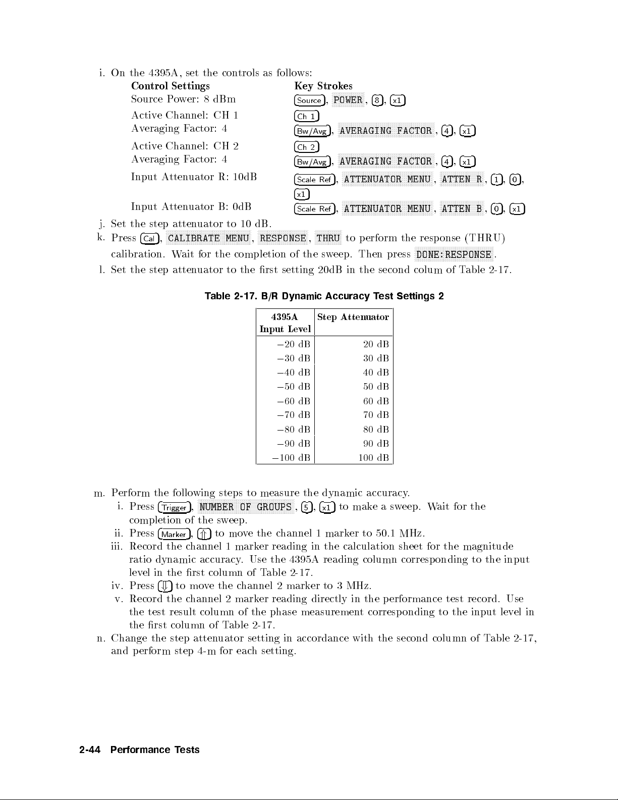
i.
On the
j.
Set the
k.
Press
calibration.
l.
Set
4395A,
Control
Source
Activ
Averaging
Activ
Av
Input A
Input
the
P
e Channel:
e
Channel:
eraging
tten
A
tten
step atten
N
N
CALIBRATE
5
4
,
Cal
step
set the
Settings Key
o
w
er:
Factor:
F
actor:
uator
uator
N
N
N
N
N
N
N
N
NN
NN
Wait
atten
8
dBm
CH 1
CH
R:
B:
uator to
NN
N
N
N
N
N
N
N
N
N
N
N
N
N
for the
uator
T
able 2-17.
controls
4
4
10dB
0dB
N
N
N
N
N
N
MENU
to
as follo
2
10
dB.
N
N
N
N
NN
NN
the
N
N
N
,
N
RESPONSE
rst
B/R
NN
completion of
N
N
N
N
N
NN
NN
setting
Dynamic
4
4
4
4
4
4
4x15
4
NN
N
N
N
ws:
Source
Ch
Bw/Avg
Ch 2
Bw/Avg
Scale
Scale
N
N
N
N
N
the
1
N
N
,
Strok
5
5
Ref
Ref
N
N
N
THRU
20dB
es
N
NN
NN
NN
NN
NN
NN
POWER
5
,
N
N
N
NN
NN
NN
AVERAGING
5
,
N
N
N
N
N
N
N
N
N
AVERAGING
5
,
N
N
N
N
N
N
N
ATTENUATOR
5
,
N
NN
N
N
N
N
ATTENUATOR
5
,
N
N
N
N
N
N
N
NN
NN
to
sw
eep.
in
Accuracy
N
N
N
N
5
,
4
,
8
NN
NN
NN
NN
N
N
N
N
N
N
N
N
N
N
N
N
N
N
N
NN
NN
NN
NN
N
N
N
N
N
N
N
NN
NN
NN
NN
N
N
N
N
N
N
N
N
N
N
N
N
N
N
N
N
N
N
NN
NN
p
erform
Then
press
the
second colum
T
est
5
4
x1
N
N
NN
NN
NN
NN
NN
NN
NN
N
N
N
N
FACTOR
N
N
N
N
N
N
N
N
N
N
N
N
N
N
NN
NN
NN
FACTOR
N
N
N
N
N
N
N
N
N
N
N
N
NN
NN
NN
NN
MENU
NN
NN
N
N
N
N
N
N
N
N
N
N
N
N
N
N
N
N
MENU
the resp
N
N
N
N
N
N
N
DONE:RESPONSE
Settings
N
N
N
N
5
,
,
4
4
NN
N
N
5
,
,
4
4
N
N
N
N
N
N
N
N
N
N
N
N
N
ATTEN
,
N
NN
N
N
N
N
N
N
N
N
NN
ATTEN
,
onse (THR
NN
NN
NN
N
N
N
N
N
N
N
N
N
N
of T
2
4
x1
4
x1
N
NN
N
N
N
N
N
N
5
5
NN
NN
NN
N
N
N
N
N
N
N
N
N
N
N
N
able
N
N
N
N
R
,
N
NN
N
B
,
NN
NN
NN
5
4
1
5
4
0
U)
N
N
N
.
2-17
5
,
,
4
0
5
,
4
x1
.
m.
P
erform
i.
ii. Press
iii.
iv. Press
v.
n. Change the step atten
and perform step 4-m for each setting.
the
follo
wing
steps to
N
NN
NN
N
N
N
N
N
N
N
N
N
N
N
N
N
N
N
N
N
N
N
NN
NN
Press
4
T
rigger
completion
4
Mark
Record
ratio dynamic accuracy
level in the rst column of T
Record the c
the test result column of the phase measuremen
the rst column of T
the
5
4
+
NUMBER
5
,
of
the
sw
5
,
5
to
4
*
er
c
hannel
to mo
vethe c
hannel 2 mark
uator setting in accordance with the second column of T
NN
OF
eep.
mov
e
1
mark
. Use the 4395A
hannel 2 mark
able
2-17.
4395A
Input
0
20
0
30
0
40
0
50
0
60
0
70
0
80
0
90 dB
0
100
measure the
N
N
N
N
N
N
N
N
N
N
N
N
N
N
N
N
GROUPS
the
c
hannel
er
reading
able 2-17.
er reading directly in the performance test record. Use
Lev
N
N
N
N
Step
A
tten
uator
el
20
dB
dB
dB
dB
dB
dB
dB
dB
dynamic accuracy
5
5
,
4
5
to
,
4
x1
1
mark
in the
er
calculation
reading column corresp onding to the input
to 3 MHz.
dB
30
dB
40
dB
50
dB
60
dB
70
dB
80
dB
90
dB
100
dB
.
mak
e
a
sw
eep.
W
ait
for
er
to
50.1
MHz.
sheet
for
the
magnitude
t corresponding to the input lev
the
able 2-17
el
in
,
2-44 Performance Tests
Page 79

12.
MAGNITUDE
Description
RATIO/PHASE
FREQUENCY
RESPONSE
TEST
(NA)
This test
through
B/R
from the
the
Specification
Magnitude
Phase frequency
T
est Equipment
Tw
T
N(m)-N(m)
Procedure
1.
Press
the
applies the
a
p
o
w
measuremen
ideal
deviation
@
0
10
dBm
@
0
10
dBm
o-W
a
y
P
yp
e-N
Cable,
4
Meas
con
trols
from
ratio
o
5
,
RF OUT
er
splitter.
ts.
magnitude
linear
accuracy
input,input
resp
input,input
w
er
Splitter
61
adapter
N
N
N
N
N
N
N
N
N
N
N
ANALYZER TYPE
as
follo
It
The magnitude
ratio
phase.
onse
cm
(t
w
:
:
::
NN
N
N
N
N
N
N
N
N
N
N
N
N
N
N
N
N
ws:
signal to
then
measures
v
alue
(A/R,
att.= 10
(Deviation
att.=
10
:
:
:
:
::
::
o
required)
::
:
:
:
:
:
:
N
N
N
N
N
N
N
N
N
N
N
NN
N
N
N
NETWORK ANALYZER
,
the 4395A
the
ratio frequency
of
0
dB.
The
B/R)
dB,Freq.
from
Linear
dB,F
req.
::
::
:
:
:
:
:
:
:
:
:
:
:
:
:
:
:
:
:
:
:
:
:
:
:
:
:
N
N
N
N
N
N
N
NN
N
N
N
N
N
N
N
N
N
N
N
N
N
N
N
N
N
N
N
N
R
input
magnitude
response
phase
100
Hz,IF
Phase)
100
Hz,IF
:
:
:
:
:
:
:
:
:
:
:
:
:
::
::
:
:
:
:
::
::
:
N
N
N
NN
N
N
N
N
N
N
N
N
N
N
N
N
,
and
ratio
frequency
BW
(A/R,
BW
:
:
::
::
:
:
:
:
:
:
:
:
:
:
:
5
4
Preset
either
and
phase
is measured
resp
3
kHz,
B/R)
3 kHz,
::
::
:
:
:
:
:
:
:
:
:
:
:
:
:
11500B
:
:
:
:
:
:
:
:
:
to
initialize
the
onse
:
:
:
:
:
:
as
:
:
the
A
:
of
23
23
:
:
::
or
B
input
the A/R
the
deviation
is
measured
C
6
5
C
6
5
:
:
:
:
:
:
or
part
::
:
PN
4395A
and
:
:
<
:
:
:
<
::
::
:
11667A
of
11851B
1250-1475
.
Then
as
6
2dB
6
12
set
Con
trol
Settings
Statistics:
Dual Channel:
Source
IF
BW: 1
Input A
Input A
Input A
2.
|A/R Magnitude Ratio/Phase F
a. Connect the test equipmen
ON
On
P
o
w
er:
0
4
dBm
kHz
ttenuator R: 10 dB
ttenuator
ttenuator B: 10 dB
A: 10 dB
Key
Strok
NN
N
N
N
4
Utilit
c
hanges
4
Displa
c
hanges
4
Source
4
Bw/Avg
4
Scale Ref
4
Scale Ref
4
Scale Ref
requency Response T
t as sho
wn in setup 1 of Figure
STATISTICS
5
,
y
to
N
N
N
DUAL
5
,
y
to
N
NN
N
POWER
5
,
N
5
,
5
,
5
,
5
,
es
N
N
N
N
N
N
N
N
N
N
N
N
N
N
N
N
N
N
NN
NN
N
N
N
N
N
N
N
N
N
N
N
N
N
N
N
N
N
on
N
N
N
N
N
N
N
N
N
N
N
N
N
N
N
N
N
STATISTICS
N
N
N
N
N
N
N
N
DUAL
N
N
N
N
N
N
N
N
N
N
N
N
IF
NN
NNNNNNNNNNNNNNNNNNNNNNNNN
ATTENUATOR MENU
NNNNNNNNNNNNNNNNNNNNN
ATTENUATOR MENU
NNNNNN
ATTENUATOR MENU
NN
NN
NN
NN
N
N
N
N
N
N
N
N
N
N
CHAN on
N
NN
NN
NN
N
N
N
N
N
N
N
N
N
CHAN
N
N
N
N
N
N
N
5
,
,
4
-
N
N
N
NN
NN
NN
N
BW
,
4
1
NNNNNNNNNNNNNNNNNNNNNNNNN
est|
OFF
NN
N
N
N
N
N
N
N
N
N
N
N
N
N
N
N
ON
N
N
N
N
N
N
N
N
NN
NN
NN
N
N
OFF
N
N
N
N
N
N
N
N
N
N
NN
NN
NN
N
ON
5
,
4
4
x1
4
5
5
,
4
k/m
NNNNNNNNNNNNNNNNNNNN
NNNNNNNNNNNNNNNNNNNNNNNNN
NNNNNNNNNNNNNNNN
2-18.
N
N
N
N
N
N
N
N
N
N
N
N
N
N
N
N
5
NN
NN
N
N
N
NN
N
N
N
N
N
N
N
N
off
N
off
N
N
(Then
NN
N
(Then
N
N
N
,
,
,
the
N
N
N
N
N
N
.)
the
N
N
N
.
NN
NNNNNNNNNNNNNNNNNNNNN
ATTEN R
NNNNNNNNNNNNNNNNNNNNN
ATTEN A
NNNNNN
NNNNNNNNNNNNNNNNN
ATTEN B
softk
ey
softk
ey
5,4
5,4
4
0
1
NN
415,405,4x15
5,4
5,4
4
0
1
lab
lab
x1
x1
el
el
5
5
Performance Tests 2-45
Page 80

b.
Set
the
Figure
4395A
2-18.
con
A/R
trols
Magnitude
as
follo
ws:
Ratio/Phase
Frequency
Response
T
est
Setup
Control
Activ
Input
F
ormat:
Activ
Input
F
ormat:
Start
Stop
Num
c.
Press
4
d.
Set the 4395A con
Control Settings
Active Channel: CH 1
Data!Memory
Active Channel: CH 2
Data!Memory
Settings
e
Channel:
P
ort:
LOG
e
Channel:
P
ort:
PHASE
F
requency:
Frequency:
b
er
of
5
,
T
rigger
A/R
MA
A/R
P
oin
ts: 500
N
N
N
N
N
N
N
N
N
N
N
N
N
N
N
N
NN
SINGLE
trols as follo
CH
1
G
CH
2
1
MHz
500 MHz
NN
to
make
asw
ws:
Key
Strok
5
4
Ch
1
4
5
Meas
4
F
o
rmat
4
5
Ch 2
4
5
Meas
4
F
ormat
4
5
,
Start
5
,
4
Stop
4
Sw
eep
eep. W
Key Strok
5
4
Ch 1
4
Display
4
5
Ch 2
4
Display
es
N
N
N
N
N
N
N
NN
N
N
A/R
,
N
NN
N
N
N
N
N
N
N
N
N
N
N
N
N
LOG
5
,
N
,
5
,
4
4
5
5
,
ait for
MAG
N
N
N
N
N
N
N
N
NN
A/R
N
NN
NN
N
N
N
N
N
N
N
N
N
N
N
PHASE
5
,
4
1
M/
5
5
,
4
,
4
0
N
NN
NN
N
N
N
N
N
N
N
N
N
N
N
N
N
NUMBER
the completion
es
NNNNNNN
NNNNNNNNNNNNNNNNNNNNNNNNN
DATA!MEMORY
5
,
NNNNNNNNNNNNNNNN
DATA!MEMORY
5
,
N
N
N
N
N
N
N
N
5
5
,
4
0
M/
N
N
N
N
N
N
NN
NN
NN
N
N
N
N
N
of
POINTS
NNNNNN
NNNNNNNNNNNNNNNNNNNNNN
5
N
N
N
N
N
N
N
N
N
N
N
N
N
N
N
5
,
4
5
of the
,
5
,
4
0
sweep.
5
,
4
4
x1
0
e. Reverse the cable connections of the 4395A A and R inputs as shown in setup 2 of
Figure 2-18.
f.
Press
4
Trigger
NNNNNNNNNNNNNNNNNNNN
5
,
SINGLE
to makeasweep. Wait for the completion of the sweep.
5
g. Set the 4395A controls as follows:
Control Settings Key Strokes
2-46 Performance Tests
Page 81

h.
Press
maxim
maxim
i.
Record
magnitude
j.
Press
N
N
N
N
N
N
N
N
MKR
v
ary the
k.
Press
mean v
the
l.
Press
and
minim
Activ
e Channel:
Data Math:
Auto
Scale
Activ
e
Channel:
Data
Math:
Auto
Scale
4
5
,
Ch 1
um
and
um
and
the larger
ratio).
5
4
,
Ch
N
2
N
N
N
N
N
N
N
N
N
NN
N
N
N
N
N
N
!
DELAY
electrical dela
NN
N
N
N
N
N
N
N
N
N
PHASE
alue
displa
y
4
Sea
rch
minim
um
p
N
N
N
N
N
N
.
um
N
N
N
N
is
5
oin
DA
T
D
A
T
NN
5
4
4
N
N
,
,
Search
minim
minim
value
Ma
rk
er
!
N
N
N
N
N
N
N
N
N
N
N
N
N
N
N
N
ELECTRICAL
,
N
N
NN
NN
NN
NN
N
N
N
N
N
N
N
N
N
displa
N
N
N
N
N
N
N
N
N
MAX
p
oin
ts.
N
y
and
ts
OFFSET
NN
CH 1
A+MEM
CH
2
A+MEM
NN
NN
NN
N
N
N
MAX
and
um
p
oin
um
p
oin
in the
N
N
N
N
N
N
N
N
N
N
N
N
MKR
!
5
,
N
N
NN
N
N
N
N
N
N
N
N
N
N
N
N
N
N
yun
til
N
and
en
ed
as
a
4
Sea
rch
on
the
4
Search
ts
on
ts.
p
erformance
NN
NN
N
N
N
N
N
N
N
N
STOP
N
N
N
N
N
N
N
N
N
NN
N
DELAY
the
ter
the
mark
NN
N
N
MIN
5
,
trace.
5
,
the
N
N
N
N
N
,
4
Cal
N
N
N
N
.
Then
trace
trace
er
statistic
N
N
N
N
N
N
N
to
Compare
4
Ch
4
Displa
455
,
4
Scale
4
Ch
4
Displa
455
,
4
Scale
NN
NN
NN
NN
MIN
trace.
5
,
is
mo
5
1
5
,
y
5
4
x1
5
Ref
5
2
5
,
y
5
4
x1
5
Ref
N
N
N
to
test
N
N
N
N
N
N
N
N
N
N
N
MORE
press
in
the
mean v
(mean)
v
e
the
the
N
NN
NN
NN
NN
NN
NN
N
N
N
N
N
DATA
,
N
N
N
DATA
,
mo
Compare
N
NN
,
N
MATH [xxx]
N
N
N
N
N
N
N
N
NN
NN
NN
NN
AUTO
N
N
N
N
N
N
N
N
N
N
N
N
N
N
N
N
MATH
N
N
N
N
NN
NN
NN
NN
N
N
N
AUTO SCALE
v
e
the
record
N
N
N
N
N
N
N
N
N
N
N
N
NN
ELECTRICAL
5
or
4
*
most
alue using
in
c
hannel
absolute
N
N
N
N
N
NN
NN
NN
NN
NN
NN
NN
N
N
N
N
N
N
SCALE
N
NN
NN
NN
N
N
N
N
N
N
[xxx]
N
N
N
N
N
N
N
N
N
N
N
N
N
c
hannel
the
(\T
est
NN
N
N
N
N
N
N
N
N
N
N
N
5
and
4
+
horizon
the
2
values
NN
NN
NN
N
N
N
N
N
N
N
N
N
N
N
N
N
N
N
N
N
N
N
N
N
N
N
N
N
N
NN
N
NN
N
1
absolute
Result"
N
N
N
N
N
N
N
N
N
N
NN
NN
DELAY
turn
tal
numeric
upp
er
mark
er
N
NN
NN
NN
NN
NN
NN
DATA+MEM
,
N
N
N
N
N
N
N
N
N
N
N
N
DATA+MEM
,
mark
v
alues
column
N
N
N
N
N
N
N
N
N
N
N
N
N
N
N
N
MENU
the
p
osition.
keys.
righ
t-hand
to
the
at
the
N
N
N
N
N
N
N
N
N
N
N
NN
N
N
N
N
N
N
N
N
NN
NN
NN
er
to
the
at
N
N
N
N
N
NN
N
,
RPG
The
maximum
maxim
N
NN
NN
NN
GAIN
,
N
N
N
N
N
N
N
GAIN
,
the
for
knob
trace
corner
um
NN
NN
N
N
N
N
A/R
and
NN
N
N
to
N
5
,
4
,
.
N
5
,
,
4
.
of
m.
*
|B/R
Connect
Record
phase).
Magnitude
the
the larger
Ratio/Phase
test
equipmen
v
alue
in
the
p
erformance
F
requency
t
as
sho
wn
in
setup
Resp
test
onse T
1
of
Figure 2-19
record
est|
(\T
est
.
Result"
column
for
A/R
Performance Tests 2-47
Page 82

Set
the
Figure
4395A
con
2-19.
trols
B/R
Magnitude
as
follo
ws:
Ratio/Phase
Frequency
Response
T
est
Setup
Control
Activ
Input
F
ormat:
Activ
Input
F
ormat:
Start
Stop
Num
Press
4
Set
the 4395A con
Control Settings
Active Channel: CH 1
Data!Memory
Active Channel: CH 2
Data!Memory
Settings
e
Channel:
P
ort:
LOG
e
Channel:
P
ort:
PHASE
F
requency:
Frequency:
b
er
of
5
,
T
rigger
B/R
MA
B/R
P
oin
ts: 500
N
N
N
N
N
N
N
N
N
N
N
N
N
N
N
N
NN
SINGLE
trols as follo
CH
1
G
CH
2
1
MHz
500 MHz
NN
to
make
asw
ws:
Key
Strok
5
4
Ch
1
4
5
Meas
4
F
o
rmat
4
5
Ch 2
4
5
Meas
4
F
ormat
4
5
,
Start
5
,
4
Stop
4
5
Sw
eep
eep. W
Key Strok
5
4
Ch 1
4
Display
4
5
Ch 2
4
Display
es
N
N
N
N
N
N
N
NN
N
N
B/R
,
N
NN
N
N
N
N
N
N
N
N
N
N
N
N
N
LOG
5
,
N
,
5
,
4
4
,
ait for
MAG
N
N
N
N
N
N
N
N
NN
B/R
N
NN
NN
N
N
N
N
N
N
N
N
N
N
N
PHASE
5
,
4
1
M/
5
5
,
4
,
5
N
4
0
NN
NN
N
N
N
N
N
N
N
N
N
N
N
N
N
NUMBER
the completion
es
NNNNNNN
NNNNNNNNNNNNNNNNNNNNNNNNN
DATA!MEMORY
5
,
NNNNNNNNNNNNNNNN
DATA!MEMORY
5
,
N
N
N
N
N
N
N
N
5
5
,
4
0
M/
N
N
N
N
N
N
NN
NN
NN
N
N
N
N
N
N
of
POINTS
NNNNNN
NNNNNNNNNNNNNNNNNNNNNN
5
N
N
N
N
N
N
N
N
N
N
N
N
N
N
,
4
5
of the
5
,
4
5
,
0
sweep.
5
5
,
4
4
x1
0
Reverse the cable connections of the 4395A A and R inputs as shown in setup 2 of
Figure 2-18.
NNNNNNNNNNNNNNNNNNNN
Press
4
5
,
Trigger
SINGLE
to makeasweep. Wait for the completion of the sweep.
Set the 4395A controls as follows:
Control Settings Key Strokes
2-48 Performance Tests
Page 83

Activ
Data Math:
Auto
Activ
Data
Auto
Press
and
minim
minim
e Channel:
Scale
e
Channel:
Math:
Scale
4
5
,
Ch 1
um
um
p
oin
4
Search
p
ts.
DA
D
oin
CH 1
T
A+MEM
CH
A
T
A+MEM
NN
NN
NN
5
,
MAX
ts
on
5
4
Ch
1
N
NN
NN
NN
NN
NN
NN
N
N
N
N
N
N
N
N
N
N
N
NN
NN
NN
NN
NN
NN
NN
NN
NN
N
N
SCALE
N
NN
NN
NN
N
N
N
N
N
N
N
N
N
N
N
N
c
hannel
NN
N
N
N
N
N
N
N
N
N
N
N
N
N
N
[xxx]
N
N
N
N
N
NN
v
alues
DATA
4
5
,
Displa
y
4x15
4
Scale
2
NN
N
N
N
and
4
Search
the
trace.
4
Ch
4
Displa
4x15
4
Scale
NN
NN
5
,
MIN
Compare
5
Ref
5
2
5
,
y
5
Ref
NN
NN
N
N
N
to
mo
the
MATH [xxx]
N
N
N
N
N
N
N
N
NN
NN
NN
AUTO
,
N
N
N
N
N
N
N
N
N
N
N
N
N
N
N
N
N
N
DATA
,
N
MATH
N
N
N
N
NN
NN
NN
NN
N
N
AUTO SCALE
v
e
the
absolute
N
NN
NN
NN
NN
NN
NN
N
NN
N
N
N
N
N
N
N
N
N
,
N
N
N
N
N
N
N
N
N
N
N
NN
,
N
1
at
N
DATA+MEM
N
N
N
N
N
N
N
N
N
N
N
N
N
N
N
DATA+MEM
mark
er
the
maxim
N
NN
NN
NN
NN
NN
NN
GAIN
N
N
N
N
N
N
N
N
GAIN
maxim
um
N
N
N
N
and
N
5
,
N
N
,
5
4
,
4
,
.
5
5
5
,
,
4
4
5
.
um
N
N
N
N
N
N
N
N
N
NN
,
N
N
N
N
N
NN
NN
NN
,
to
the
Record
magnitude
Press
N
N
N
N
ELECTRICAL
dela
Press
value
Press
minim
p
oin
Record
phase).
N
N
N
N
N
N
N
N
N
N
yun
ts.
the
4
Ch
N
N
N
N
NN
N
N
N
N
til the
NN
N
N
N
N
N
N
N
PHASE
is
displa
4
Sea
rch
um
the
2
N
N
larger v
ratio).
5
,
4
Ma
N
N
N
N
N
N
N
N
N
N
N
DELAY
N
N
N
N
N
N
N
N
N
NN
OFFSET
y
N
N
MAX
5
,
p
oints
larger
alue in
rk
er
!
N
N
N
N
N
N
N
NN
N
N
N
N
trace is
NN
NN
NN
N
N
N
N
N
N
N
ed
as
N
N
N
N
N
NN
NN
and
on
v
alue
5
N
.
N
N
N
the
N
a
N
N
N
N
N
MKR
,
Then
in
and
mark
4
Sea
trace.
in
the p
N
N
N
N
N
!
the
en
rch
the
N
N
NN
NN
N
STOP
press
ter
er
5
N
,
N
N
most
statistic
p
N
N
N
N
MIN
Compare
erformance
N
N
N
N
N
N
N
5
,
,
4
Cal
5
or
*
horizon
trace
NN
NN
to
4
+
(mean)
mo
the
4
the
N
N
N
N
N
erformance
test
N
N
N
N
N
N
N
N
N
N
N
N
NN
MORE
5
and
tal
p
mean v
v
e
the
absolute
test
record
N
N
ELECTRICAL
,
turn
osition.
in
record
(\T
N
N
N
N
N
N
N
N
N
N
NN
NN
N
N
the
alue using
the
upp
c
hannel
v
alues
(\T
N
N
N
N
N
RPG
er
2
N
est
Result"
N
N
N
N
N
N
N
N
N
N
N
DELAY
numeric
righ
mark
at
est
Result"
N
N
NN
NN
N
N
N
knob
t-hand
er
the
N
N
N
N
N
N
N
N
N
N
N
MENU
to
keys.
to
the
maxim
column
N
N
N
N
N
N
N
N
NN
N
,
v
ary
The
corner
maxim
um
column
N
N
N
N
N
MKR
the
and
for
N
N
N
trace
of
for
A/R
N
N
N
NN
NN
N
N
N
N
N
N
N
N
N
!
DELAY
electrical
mean
the
displa
um
and
minim
A/R
N
N
N
N
N
N
N
,
y
.
um
Performance Tests 2-49
Page 84

13.
DISPLAYED
Description
AVERA
GE
NOISE
LEVEL
TEST
(SA)
This test
lev
el
In
this
measured
the
in
data
uses the
the
test,
v
with
4395A
the
alues are
Specification
Displa
y
ed
a
freq.
1 kHz,
freq.
100
freq.
10
1:
f
T
est
Equipment
50
T
ermination
Procedure
1.
Connect
the
4395A mark
sp
noise
the
mark
v
erage
kHz,
MHz,
is
measuremen
test
ectrum
lev
el
(trace
conv
erted to
er
statistics
noise
lev
ref. lev
(three
ref.
ref.
el
lev
lev
t
frequency
required)
equipmen
er statistics
analyzer
mean
log magnitude
function.
el
0
40
el
0
40
el
0
40
(MHz).
t
as
sho
mo
v
dBm,
dBm,
dBm,
:
:
:
:
wn
function to
de.
alue)
is measured
att.=0
att.=0
att.=0 dB
:
:
::
::
:
:
in
Figure 2-20
format
dB
dB
:
:
:
:
:
measure
in linear
[dBm].
:
:
:
:
:
:
:
:
:
:
:
::
:
:
:
:
:
:
:
:
:
.
:
:
:
::
:
:
:
909C
the
This
:
:
:
::
::
:
:
displa
:
:
:
Opt.
y
ed
format [W
is
done
:
::
::
::
:
:
::
:
:
:
:
:
:
<
[
0
145+
012
a
v
erage
att]. Then
to
a
v
oid
:
<
0
120
:
:
<
0
133
1
/100]
f
or
part
noise
the
sk
ewing
dBm/Hz
dBm/Hz
dBm/Hz
of
85032B
2-50 Performance Tests
Figure 2-20. Average Noise Level Test Setup
Page 85

2.
3.
4.
Press
4
Meas
set
the
con
Con
trol Settings
Reference Lev
Input
Input
Input
UNIT:
Statistics: ON
Detection:
Press
4
Meas
P
erform
a.
Set
the
the rst
Con
Cen
RBW:
F
requency
5
,
trols
Atten
A
A
W
5
,
the
con
settings
trol
ter
tten
tten
NN
NN
N
N
N
N
N
N
N
N
N
N
N
N
N
as
el:
uator
uator
uator
ATT
Sample
NN
N
to
set
wing
trols
Settings
F
requency:
3
Hz
Span:
NN
follo
as
listed
ANALYZER
N
N
R
follo
NN
NN
NN
NN
NN
TYPE
ws:
0
40 dBm
R:
A:
B:
the
steps
follo
N
N
N
N
N
N
N
N
N
0
dB
0
dB
0
dB
4395A
ws.
in
1
30
Hz
NN
NN
N
N
N
N
N
SPECTRUM
,
to
test
(This
T
able
kHz
N
to
N
N
N
N
N
N
N
N
the
the
2-18
N
N
NN
NN
NN
NN
NN
NN
N
N
N
N
N
ANALYZER
Key Strok
4
Scale
Ref
4
Scale
Ref
4
Scale Ref
4
Scale Ref
4
5
F
o
rmat
4
5
,
Utilit
y
c
hanges
4
5
,
Meas
R
input.
displa
sets
the
).
Key Strok
4
Center
4
Bw/Avg
4
Span
N
N
N
N
N
N
N
N
NN
NN
NN
NN
NN
N
,
es
N
N
N
N
N
N
N
N
N
N
NN
REFERENCE
5
,
N
N
N
N
N
N
NN
NN
NN
ATTENUATOR
5
,
N
N
NN
NN
NN
NN
N
N
ATTENUATOR MENU
5
,
NN
NN
NN
N
N
N
N
N
N
ATTENUATOR
5
,
NN
N
N
N
N
N
N
N
N
N
N
N
N
WATT
,
N
N
N
N
N
N
N
N
N
N
N
N
N
N
N
NN
STATISTICS
N
N
N
N
DETECTION[xxx]
y
cen
5
NN
N
N
N
N
N
N
N
N
N
STATISTICS
to
N
N
N
N
N
N
NN
NN
NN
N
N
N
N
ed
av
erage
ter frequency
es
5
5
,
,
4
1
N
N
N
N
N
N
RES BW
5
,
5
,
,
4
4
3
0
NN
NN
N
N
N
N
NN
N
N
N
4
N
N
5
4
NN
NN
N
N
N
N
NN
N
N
N
N
k/m
N
N
,
Preset
NN
NN
NN
NN
NN
NN
N
N
N
N
N
N
N
N
N
N
N
N
N
N
N
N
N
N
N
N
N
N
N
NN
NN
NN
NN
N
N
N
N
N
N
N
5
NN
NN
N
N
N
N
4
x1
5
N
N
N
N
N
N
N
N
N
N
N
N
N
NN
NN
NN
NN
N
N
N
N
N
on
N
N
N
N
N
N
N
N
N
NN
noise
N
N
,
5
to
N
N
N
N
N
N
N
NN
NN
VALUE
N
N
N
NN
NN
NN
NN
MENU
NN
NN
NN
N
N
N
NN
N
N
N
N
N
N
N
MENU
N
N
N
N
N
N
NN
NN
OFF
N
N
N
N
N
N
N
N
N
N
ON
NN
NN
N
N
N
,
,RBW
5
,
4
3
initialize
NN
NN
NN
NN
5
4
-
N
N
N
N
NN
NN
NN
N
N
ATTEN
,
N
N
NN
N
N
N
N
N
N
N
N
N
ATTEN A
,
NN
NN
N
N
N
N
N
N
N
N
N
ATTEN
,
NN
NN
N
N
N
N
N
(Then
N
N
NN
NN
NN
NN
N
N
N
N
N
N
N
off
N
N
N
N
N
N
N
N
N
N
NN
NN
NN
SAMPLE
lev
el
at
and frequency
5
4
x1
,
N
NN
NN
N
N
.)
N
4
4
NN
NN
NN
NN
N
N
N
N
N
N
N
the
the
5
,
NN
NN
N
N
N
N
N
N
N
N
NN
N
N
4395A
5
,
4
0
NN
NN
N
N
N
R
,
N
N
N
N
N
N
N
N
,
N
N
N
N
N
N
N
N
B
,
the
4395A
5
4
x1
5
4
0
5
4
0
5
4
0
softk
,
,
,
R
.
Then
5
4
x1
5
4
x1
5
4
x1
ey
input.
span
lab
el
to
T
able
2-18.
Displa
y
ed
Av
erage
Cen
ter
F
requency
1
kHz
10
kHz
100
kHz
1
MHz1kHz
11
MHz1kHz
20
MHz1kHz
101
MHz1kHz
201 MHz 1 kHz 10 kHz
499 MHz 1 kHz 10 kHz
NN
NNNNNNNNNNNNNNNNNN
SINGLE
5
b. Press
c. Record the 4395A trace mean v
d. Change the center frequency, frequency span, and RBW settings in accordance with
5.
Press
4
column). The trace mean value is displayed as a marker statistic (mean) in the upper
right-hand corner of the display.
Table 2-18. Then rep eat steps 4-b and 4-c for each setting.
4
Meas
,
Trigger
NNNNN
5
,
A
to set the 4395A to the A input.
to mak
e
asw
eep. Wait for the completion of the sw
alue [Unit] in the calculation sheet (\T
4395A
RBW F
3
Hz
10
Hz
10
Hz
Noise
requency
Lev
el
100
100
10
10
10
10
Test
Span
30
kHz
kHz
kHz
kHz
Settings
Hz
Hz
Hz
eep.
race Mean [Unit]"
Performance Tests 2-51
Page 86

6. Rep
7.
Press
8.
Rep
eat step
4
Meas
eat
step
5
4to
N
N
B
,
4
N
N
N
to
to
test the
set
the 4395A
test
the
display
displa
ed a
to the
yed
verage
B input.
av
erage noise
noise
lev
level
el
at
the
at the
4395A
A
4395A B
input.
input.
9. Con
calculation
vert
the unit
of the
sheet. Record
test results
the
test
from [W
results
att] to
[dBm]
in
[dBm]
the
p
using
the
erformance
equation
test
record.
giv
en
in
the
2-52 Performance Tests
Page 87

14.
AMPLITUDE FIDELITY
Description
TEST (SA)
This test
applied
inserting
value
inserted
The
error sources
accuracy
the
omitted.
The
the
of
10
These
determined b
6
and
output
reduce
measuremen
Specification
chec
to
the
kno
wn
at
the
atten
atten
amplitude
at RBW
in
the
Magnitude
amplitude delit
delit
y
is
kHz
and
tests
are
y
10
dB
xed
connector and
the
measuremen
t
ks the
uation's
not
uncertain
4395A amplitude
4395A
attenuation
uator
delit
y
4395A
R
atio/Phase
yp
c
hec
at
signal lev
not
necessary
the
delit
atten
R
input
values.
setting
calibrated
p
erformance
3
kHz are
net
w
ork
Dynamic
erformance
k
ed
at
signal
els
y
at
higher
uators
the 4395A
t
uncertain
ties
listed
through
of
10
v
alues.
exactly
analyzer
lev
0
50
b
ecause
with
a
S
input,
ties
in
delity
a
Each
dB.
at
RBWs
A
c
at
lo
els
dB
the
signal
VSWR
caused
the
p
at
RBW
step
atten
uator.
signal amplitude
Then
the
measured
3 kHz
same
as
those
mo
de.
Because
cur
acy
Test
,the
w
signal
(from
delit
lev
resp
erformance
0
els
of
lev
60
dB
the
y
and
ectiv
b
y
mismatc
p
els
(from
reference
erformance
1.015
ely
test
of
are not
the
are
the
are
.
These
10
kHz.
The
signal
[dB]
v
alues
of
the
dynamic
delity
not
the
reference
lev
delit
connected
xed
h error.
record
A
50.1
amplitude
is
measured
are
tested in
magnitude
accuracy
test
at
tested
el)
at these
y
at
at
atten
When
are
an
v
in
an
alid.
MHz
to
compared
this test.
ratio
the
RBW
this
test.
lev
el)
RBW
levels
are theoretically
RBW
to
the
uators
they
of
signal
are
CW
is
v
a
reference
with
The
dynamic
is
tested
at an
of
1
3
are
used,
signal
aried b
to
in
3
kHz
That
is,
RBW
MHz.
kHz.
generator
used
to
the
is
y
the
is
Amplitude
Log
Test Equipment
Signal Generator
Step A
Attenuator Driver
Type-N Cable, 61 cm (two required)
BNC cable, 122 cm
6 dB Fixed Attenuation, VSWR1.015
10 dB Fixed Attenuation, VSWR1.015
delit
scale
1
ttenuator
y
(relativ
0
0
30
0
40
0
50
0
60
0
70 dB
C, RBW = 10 Hz,
@2365
full sc
ale input level
::::
1
, 10 dB step, VSWR
::::::::::: :::::::::::::::::::: ::::::::::::::: ::::::::::::::: ::::
:::::::::::::: :::::::::::::::::::: :::::::::::::: :::::::::
Range
e
to
full
scale
input
dB
range
>
0
0
10 dB
0
0
0
0
0
0
30 dB
dB
>
range
dB
>
range
dB
>
range
dB
>
range
>
range
::::::::::::::: ::::::::::
lev
el)
40 dB
50
dB
60
dB
70
dB
80 dB
20 dBm
ref. value
:::::::::::::: :::::::::::
1.02
::::::::::: :::
:::::::::::::: :::::::::::::::
::::::::::::::: ::::::
:::::::::::: ::::::::
Amplitude
6
6
6
6
6
6
+30 dBm,
:::::::
0.05
0.07
0.15
0.35
0.8
1.8 dB
Fidelit
dB
dB
dB
dB
dB
ref. input level
8491A Opt. 006 & Opt. H60
8491A Opt. 010 & Opt. H60
1
y
=
:::::::::::::
8496G Opt. 001 and H60
11500B or part of 11851B
PN 8120-1840
8663A
11713A
Performance Tests 2-53
Page 88

1:
Procedure
1.
Record the
(\Calibration V
2.
Connect
Calibration
step atten
the
test
v
alues
for
atten
uator 50
alue" column).
equipmen
t
as
uation
settings
of
MHz calibration
sho
wn
in
Figure
10
dB
values
2-21
to 60
dB at
.
50 MHz
in the
are required.
calculation sheet
Note
Connect
the
4395A EXT
conguration,
same
reference
signal
generator's
REF Input
b
oth
the
frequency
on the
signal
to
10
MHz
rear
generator
obtain
panel
a
stable
frequency
as
sho
and
the
measurement.
reference output
wn
in
Figure
4395A
are
phase
2-21
to the
.
With
lo
c
k
ed to
this
the
3. Initialize
the
signal
Controls Settings
Frequency 50.1
Amplitude 6 dBm
4. Press
set the con
4
Meas
,
trols as
follows
NNNNNN
NNNNNNNNNNNNNNNNNNNNNNNNN
ANALYZER TYPE
5
Control Settings
Center F
requency: 50.1 MHz
Frequency Span: 120 Hz
RBW: 10 Hz
Video BW: 10 Hz
5.
Press
4
Meas
NNNNN
5
,
R
to set the 4395A to the R input.
2-54 Performance Tests
Figure
generator.
NNNNNNNNNN
2-21.
Amplitude
Then
set
the
con
MHz
NNNNNN
NNNNNNNNNNNNNNNNNNNNNNNNN
SPECTRUM ANALYZER
,
NNNNNNNNNNNNNNNNNNNNNN
Key Strok
5,4
4
Center
4
5,415,425,405,4x15
Span
4
4
Bw/Avg
Bw/Avg
5
,
5
,
Fidelity
trols
,
T
as
4
Preset
est
Setup
follo
ws:
5
to initialize the 4395A. Then
es
5
5,4
0
5,4
5,4
.
5,4
1
M/
5
NNNNNNNNNNNNNNNNNNNN
RES BW,415,405,4x15
NNNNNNNNNNNNNNNNNNNNNNNNNN
VIDEO BW,415,405,4x15
1
Page 89

6.
7.
8.
Press
N
NN
N
N
N
N
N
N
N
N
N
N
ATTEN
Set the
P
erform
a.
On
b.
On the
6
0.1
c.
On
sw
d.
Press
mark
e.
Set
4
Scale Ref
N
NN
NN
NN
R
the
the
eep.
the step
5
NN
step atten
er
,
N
5
,
4
,
4
1
the
follo
4395A
signal generator,
dB.
4395A
4
5
Sea
rch
on
the
NN
NN
N
N
N
N
N
N
N
N
N
N
N
N
N
5
,
,
4
x1
uator to
wing
,
press
,press
N
N
N
N
NN
NN
NN
N
MAX
,
p
eak
NN
to
steps
4
REFERENCE
5
0
,
attenuator
NN
4
4
Ma
of
NN
Sea
T
NN
set
rigger
rk
the
T
NN
NN
N
N
N
N
N
N
N
N
N
N
VALUE
the
10
dB.
to
measure
5
,
rch
adjust
5
,
N
N
1MODE MENU
5
,
er
carrier
to the
able
N
N
N
NN
NN
N
,
4395A
N
NN
NN
N
N
N
N
N
N
MAX
the
N
N
N
N
N
N
N
N
N
N
SINGLE
N
N
NN
NN
NN
NN
N
N
rst
2-19.
4
-
to
NN
NN
NN
N
N
N
N
N
(reference
Amplitude
0
1
con
trols
the amplitude
mo
v
e
amplitude
NN
N
N
to
mak
N
setting
N
N
N
N
N
N
N
N
N
N
NN
N
FIXED 1MKR
,
5
5
5
,
,
4
4
,
4
x1
the
e
N
N
N
NN
NN
NN
lev
20
Fidelity
5
,
4
Scale Ref
to the
mark
un
til
asw
NN
N
N
N
N
N
N
N
N
el of
dB
in
NN
NN
N
N
N
N
N
ATTENUATOR
5
,
reference setting
delity
eep. W
N
N
N
N
N
.
er
to
the
p
the
4395A
ait for
N
N
N
N
NN
N
to place
the amplitude
the
second
T
est
Settings
N
N
N
N
N
N
N
N
NN
NN
NN
NN
NN
NN
N
N
N
N
N
N
MENU
for the
eak
of
the
mark
er
reads
the completion
the delta
delity).
column
of
N
N
N
N
N
N
N
NN
NN
N
,
test.
carrier.
0
20
reference
T
able
dB
of
2-19
the
.
f.
g.
9. Remo
10.
Press
11.
Press
NNNNNNNNNNNNNNNNNNNNNNN
ATTEN A
P
erform the
i.
Press
ii.
Press
iii.
Record
Use the
in
the rst
Change
Table
2-19
ve the xed atten
4
Meas
4
Scale Ref
,
5
4
the
,
5
1
following
4
T
rigger
4
Sea
rch
the
\
4395A
step
.
Then
N
NNNN
A
to
NNNNNNNNNNN
5
,
5
,
4
0
dB
from
Reference
steps
N
N
N
N
N
N
N
N
N
.
uator
to
N
to
er
reading
Table
setting in
step
NNNNNNNNNNN
N
N
N
N
N
N
N
N
N
N
SINGLE
5
,
N
N
N
N
N
N
N
N
N
N
N
MAX
5
,
delta
mark
Reading"
column of
atten
p
erform
uation from the R input, and connect
set the 4395A to the A input.
NNNNNNNNNNNNNNNNNNNNNNNNN
REFERENCE VALUE
5
,
,
to set the 4395A con
4
x1
measure
mak
e
column
2-19.
8-f
,
4
-
Input
0
0
0
0
0
0
0
a
sw
in
corresp
accordance with
for
eac
5,4
5,4
1
Step
A
tten
uator
Lev
el
10 dB
20
dB
30
dB
40 dB
50
dB
60
dB
70
dB
the
amplitude
eep.
W
ait for
the
calculation
onding
h
setting.
5,4
5,4
0
trols to the reference setting for the test.
x1
Scale Ref
20
dB
30
dB
40
dB
50
dB
60
dB
70
dB
80
dB
delit
y
.
the completion
sheet
for
the amplitude
to
the
dB
from
the second
it to the A input.
NNNNNNNNNNN
NNNNNNNNNNNNNNNNNNNNNNNNN
ATTENUATOR MENU
5
,
of
the
the
reference
column of
NNNNNNNNNNN
sw
eep.
delity
,
lev
.
el
12. Set the step atten
13. Repeat step 8 to measure the amplitude delity at the 4395A A input.
14. Remove the xed attenuation from the A input, and connect it to the B input.
15.
Press
4
5
,
Meas
uator to 10 dB.
NNNNN
B
to set the 4395A to the B input.
Performance Tests 2-55
Page 90

16.
17.
18.
19.
20.
Press
4
NN
N
N
N
N
N
N
N
Scale Ref
N
N
N
N
NN
NN
NN
B
eat
results in
N
ATTEN
Set the
Rep
Calculate
test
Initialize
NN
REFERENCE
5
N
,
the
4
1
the
,
5
,
4
8
to
test
the
signal
5
0
NN
step atten
step
NN
N
N
N
N
N
N
N
N
N
N
N
N
N
NN
NN
NN
NN
5
,
,
to
4
x1
uator to
measure
results using
p
set
erformance
generator.
NN
NN
N
N
N
N
N
N
N
N
N
N
N
N
VALUE
the
10
dB.
the
amplitude
the equations
test
Then
N
NN
NN
N
,
4395A
record.
4
5
-
set
5
,
4
1
con
delity
the con
,
trols
4
0
5
,
4
x1
given
trols as
5
,
4
Scale Ref
to the
at the
in the
NN
NN
N
N
N
N
N
N
N
N
N
N
N
N
N
ATTENUATOR
5
,
reference setting
4395A B
calculation
follows:
NN
input.
NN
NN
NN
NN
NN
for the
sheet.
N
N
N
N
N
N
MENU
N
N
N
N
N
N
N
NN
NN
N
test.
Record
,
the
Controls
F
requency
Amplitude
21. Press
set
the con
Con
Cen
F
RBW:
Video
22.
Press
23.
Press
405
,
4
24.
Set
the
25.
P
erform
a.
On
b.
On
6
c.
On
sw
d.
Press
mark
e. Set the step atten
f. P
ii.
iii. Record the delta mark
5
4
Meas
trol
ter
requency
5
4
Meas
4
Scale
5
,
to
x1
step
the
the
the
0.1 dB.
the
eep.
4
Search
er
erform the follo
i.
Press
Press
N
N
N
N
NN
NN
NN
N
N
N
N
N
N
N
N
N
N
N
N
N
ANALYZER TYPE
,
trols
Settings
F
requency:
Span:
10
Hz
BW:
N
N
N
N
N
R
to
,
5
,
Ref
set
the
atten
follo
4395A
signal
4395A
5
,
on
the p
4
Trigger
4
Search
N
as
follo
120
10
Hz
set
the
N
N
N
N
N
NN
N
N
N
N
N
N
N
N
N
REFERENCE
4395A
uator
wing
,
press
generator,
, press
N
N
N
N
NN
NN
NN
N
MAX
,
eak
uator to 10 dB.
wing steps to measure the
NNNNNNNNNNNNNNNNNNNN
5
,
SINGLE
NNNNNNN
MAX
5
,
N
N
N
N
N
NN
NN
ws
50.1
N
N
N
N
N
N
N
N
to
steps
4
Sea
4
T
4
Mark
of
NNNN
.
Settings
50.1
MHz
6
dBm
N
N
N
N
NN
NN
NN
N
N
N
N
N
N
N
N
N
N
N
N
N
N
N
N
N
N
N
NN
NN
NN
N
N
N
Strok
5
,
5
,
4
1
5
,
5
,
5
5
,
4
4
1
0
reference
the
amplitude
mo
v
e
to
mak
N
N
N
N
N
N
N
N
NN
N
FIXED 1MKR
,
eep. W
N
N
N
N
N
N
N
N
N
N
N
N
N
N
N
,
es
5
5
,
,
4
4
0
5
5
5
,
,
4
4
2
N
N
N
N
N
N
N
N
NN
NN
NN
RES BW
NN
NN
NN
NN
N
N
N
N
N
N
VIDEO
5
,
,
4
4
x1
setting
the
mark
un
til
e
asw
N
N
NN
NN
NN
NN
N
N
N
N
N
N
N
lev
el
amplitude delit
ait for the completion of the sw
4
Preset
5
,
4
.
5
,
4
x1
0
N
N
N
N
N
N
,
4
N
N
N
N
N
N
N
N
N
N
BW
Scale
delit
er
the
eep. W
N
N
N
N
N
N
N
N
N
N
of
the
5
to
5
,
4
4
M/
1
5
5
,
5
4
1
0
N
N
5
,
,
4
1
N
5
,
Ref
for
the
y
.
to
the
4395A
ait for
NN
N
to
place
amplitude
initialize the
5
,
5
4
x1
5
5
,
4
4
0
x1
N
N
N
N
NN
N
N
N
N
N
N
N
N
N
N
N
N
N
N
N
test.
eak
mark
the
the
N
of
er reads
delit
ATTENUATOR
p
y.
4395A
N
N
N
N
N
N
N
NN
N
N
N
N
N
N
N
N
N
N
N
MENU
the
carrier.
completion
delta
reference
y).
NN
N
N
N
N
N
N
SPECTRUM ANALYZER
,
Key
MHz
Hz
4395A
N
N
N
N
N
N
NN
N
N
N
N
N
N
N
VALUE
con
trols to
20 dB.
to
measure
5
,
rch
adjust
5
,
rigger
N
N
N
1MODE MENU
5
,
er
the
carrier
to makeasw
er reading in the calculation sheet for the amplitude delit
to
the
N
N
N
N
N
N
N
N
,
N
N
N
N
N
N
N
NN
NN
MAX
the
N
N
N
N
N
N
N
N
N
N
SINGLE
N
NN
NN
NN
NN
N
N
4
Center
4
Span
4
Bw/Avg
4
Bw/Avg
R input.
5
,
4
-
the
to
amplitude
N
N
N
N
N
N
NN
NN
N
N
N
N
N
N
N
N
N
(reference
N
N
0
N
N
,
.
N
N
N
N
ATT
30
eep.
Then
N
NN
N
N
N
N
N
dB
of
the
N
N
N
N
N
R
,
y.
26. Remo
27.
28.
29. Set the step attenuator to 20 dB.
2-56 Performance Tests
ve the xed atten
Press
4
Meas
Press
4
Scale Ref
405,4x15
, to set the 4395A controls to the reference setting for the test.
uation from the R input, and connect
NNNNN
5
,
A
to set the 4395A to the A input.
NNNNNNNNNNNNNNNNNNNNNNNNNNNNNNNNNNNNNNNNNNNNNNN
5
,
REFERENCE VALUE,4-5,415,405,4x15,4
Scale Ref
it to the A input.
NNNNNNNNNNNNNNNNNNNNNNNNNNNNNNNNNNNNNNNNNNNNNNN
5
,
ATTENUATOR MENU
NNNNNNNNNNNNNNNNN
,
ATT A
,
Page 91

30.
Repeat
step 25
to measure
the amplitude
delity
at the
4395A
A
input.
31. Remo
32.
Press
33.
Press
405
,
4
34.
Set the
35.
Rep
eat
x1
ve
4
Meas
4
Scale
5
the
,
to
step
step
xed
N
NN
NN
5
B
,
5
,
Ref
set
the 4395A
atten
25
atten
uation
to set
the 4395A
N
NN
NN
N
N
N
N
N
N
N
N
N
N
N
NN
NN
REFERENCE
uator
to
to
measure
NN
NN
NN
NN
NN
N
N
VALUE
controls
20
the
from
to the
N
N
N
N
N
N
N
N
N
NN
NN
NN
to the
dB.
amplitude
the
A
input,
B
input.
5
5
,
,
4
,
4
1
-
reference setting
delit
and
connect
5
5
,
,
4
4
4
0
x1
y
at the
Scale
it
N
NN
NN
ATTENUATOR
5
,
Ref
for
the
4395A B
to the
N
N
N
N
N
N
N
N
N
N
N
test.
input.
B input.
NN
NN
NN
NN
NN
NN
NN
N
N
N
N
N
N
MENU
N
NN
NN
N
N
N
N
N
N
N
N
N
N
N
ATT
N
B
,
N
N
N
N
N
NN
NN
NN
,
Performance Tests 2-57
Page 92

15.
INPUT A
Description
TTENUATOR
SWITCHING
UNCERT
AINTY
TEST
(SA)
This test
from
In
this
The
measuremen
uncertain
to k
atten
4395A
the input
Specification
A
T
est
Signal
Step
A
T
BNC
6dB
measures the
0
dB
to
test,
a
signal
eep the
input atten
@0
@40
tten
yp
amplitude is
t,
t
y
exclusiv
signal lev
uator)
constan
input
attenuator
dB
to
dB
to
Equipment
Generator
A
tten
uator driv
e-N
Cable,
cable,
Fixed
atten
uator
50
dB.
The
50.1
MHz
the
other
ely
el input
t.
F
uator
setting
uator
switc
30
dB, referenced
50
dB,
:
:
1
,
10
2
:
er
61
cm
122
cm
A
tten
uation,
4395A input
switc
hing
CW
signal
measured at
measuremen
.
The
applied
to
or
example,
is
increased
0
40
hing
uncertain
referenced
:
:
:
:
:
:
:
::
:
dB
step,
:
::
:
:
:
:
:
:
:
(t
w
o
required)
:
:
:
:
:
:
:
:
:
:
VSWR
attenuator
uncertain
is
each
t
signal
the
rst
the
b
dB.
to 10
to
10
:
:
:
:
:
VSWR
:
:
:
:
:
:
:
::
::
t
applied
4395A input
conditions
level
mixer
step
atten
y
10
dB. The
This
k
eeps
t
y
dB
:
::
dB
:
:
:
:
:
:
:
:
:
:
1.02
:
:
:
:
:
:
:
:
:
:
:
:
:
:
:
:
:
:
:
:
:
1.015
(t
switching
y
is
referenced
to
the 4395A
are
k
is con
(the
in
uator
4395A reference
the
:
:
:
:
:
:
:
:
:
:
::
::
:
:
:
:
:
:
:
:
:
:
:
:
:
:
:
:
:
:
:
::
:
:
:
:
:
:
:
:
:
:
:
:
:
:
:
:
:
:
:
w
o
required)
uncertain
to
the
input through
atten
uator
ept
constan
trolled using
ternal
4395A
:
:
:
:
:
:
:
is
decreased
:
:
:
:
:
:
:
:
:
:
::
:
:
:
:
:
:
:
:
:
:
:
:
:
:
:
:
:
:
:
:
:
:
:
:
circuit
in
ternal
:
:
:
::
:
:
:
:
:
:
:
:
::
:
:
:
:
:
:
:
:
:
:
::
::
:
:
:
:
t
setting.
t
to
::
::
:
:
:
:
:
:
:
:
:
:
:
:
:
:
::
:
:
:
:
:
:
8491A
y
o
v
er
10 dB
measure
the step
stage
follo
b
y
10
level
is
IF
gain
::
:
:
:
:
:
:
:
:
::
:
:
:
:
:
:
:
:
8496G
:
:
:
:
:
:
:
:
11500B
:
:
:
:
:
:
:
Opt.
the
en
tire
attenuator
a step
A
dB,
:
:
::
:
t
eac
the
atten
wing
set
constan
:
:
:
:
::
:
:
:
:
:
:
Opt.
:
:
:
or
:
:
:
:
006
attenuator.
h
switc
uator
when
to
the
:
:
:
:
:
:
:
:
:
::
:
001
:
:
:
:
part
:
PN
&
range
setting.
hing
so
the
input
the
v
alue
t.
:
<
6
1.0
:
<
6
1.5
:
:
:
:
:
8663A
and
:
:
:
:
11713A
of
11851B
8120-1840
Opt. H60
as
of
dB
dB
H60
1:
Calibration
Procedure
1.
Record the
(\Calibration
2.
Set the step atten
3. On the signal generator, initialize the signal generator. Then set the con
Controls Settings
Frequency 50.1 MHz
Amplitude +12 dBm
4. Connect the test equipment as shown in Figure 2-22.
Note
2-58 Performance Tests
v
alues
for
atten
uation
settings
step atten
Value"
Connect the signal generator's 10 MHz frequency reference output to the
4395A EXT REF Input on the rear panel as shown in Figure 2-22. With this
conguration, both the signal generator and the 4395A are phase locked to the
same reference frequency to obtain a stable measurement.
uator 50
column).
uator to 40 dB.
MHz calibration
of
10
dB
to
50
dB
at
v
alues
in
50 MHz
the
are required.
calculation
sheet
trols as follo
ws:
Page 93

N
N
NN
NN
N
N
N
N
5.
Press
4
Meas
set
the
con
Con
trol
Cen
ter
F
requency
RBW:
Scale/Division:
6.
Press
4
Meas
7.
Press
4
N
N
ATTEN R
8.
P
a.
b.
c. Set the 4395A con
Scale
N
N
N
N
N
N
NN
NN
NN
N
N
N
N
N
N
N
N
N
,
erform
the
Press
4
Trigger
Press
4
Search
marker on the
the rst settings listed in T
Control Settings Key Strok
Input A
Reference Level:040 dBm
N
ANALYZER
5
,
trols
as
Settings
F
requency:
Span:
10
Hz
N
N
N
N
N
R
5
to
,
N
N
N
REFERENCE
5
,
Ref
5
,
5
,
4
4
1
0
follo
wing
5
,
NNNNNN
5
,
ttenuator R: 0 dB
Figure
N
N
N
N
N
N
N
N
N
N
N
follo
5
set
N
N
N
NN
NN
NN
N
N
5
4
x1
N
N
N
N
N
N
N
N
N
N
N
SINGLE
NNNNN
MAX,4
peak of the carrier.
trols as follo
N
N
N
N
N
NN
NN
N
N
N
N
N
TYPE
ws:
50.1
120
Hz
dB/Div
the
4395A
N
N
N
N
N
N
N
N
N
N
N
N
N
N
,
to set
steps to
NN
N
N
N
N
N
N
N
to
Marker
2-22.
Input
N
N
NN
NN
N
N
N
N
N
N
N
N
SPECTRUM
,
MHz
to
N
N
NN
NN
NN
N
N
N
N
N
N
N
N
VALUE
the
4395A
measure the
mak
e
NNNNNN
NNNNNNNNNNNNNNNNNNNNNNNNN
1MODE MENU
5
,
ws. This sets the input atten
able 2-20
A
ttenuator
N
N
N
N
N
N
N
N
N
N
N
N
N
N
N
N
N
N
N
NN
NN
N
ANALYZER
Key
Strok
5
4
Center
5
,
4
Span
4
Bw/Avg
4
Scale
Ref
the
R
input.
N
N
5
5
,
4
-
sw
4
3
con
eep.
.
4
Scale Ref
4
Scale Ref
,
N
,
a
Accuracy
N
N
N
N
N
N
N
N
N
N
N
N
N
N
N
N
N
N
N
N
N
,
es
5
,
4
4
0
trols
input atten
W
,
5
,
4
1
5
,
5
5
NNNNNN
FIXED 1MKR
,
4
5
0
5
5
,
,
4
4
0
2
N
N
N
N
N
N
N
N
N
N
N
N
N
NN
N
RES
BW
N
N
N
N
N
NN
NN
N
N
N
N
SCALE/DIV
,
5
,
,
4
4
x1
Scale
to
the
ait
for
NNNNNNNNNNNNNNNNNNNNNNNNN
es
NNNNNNNNNN
ATTENUATOR MENU
5
,
NNNNNNNNNNNNNNNNNNNN
5
,
REFERENCE VALUE,4-5,445,405,4x15
T
est
Setup
5
to
4
Preset
5
,
4
4
.
5
,
4
x1
N
N
N
N
,
4
N
N
N
N
N
N
N
N
N
N
reference
uator switc
the
NNNNNNNNNNNNNNNNNNNNNNNNN
initialize
5
5
,
4
1
M/
5
5
5
,
4
,
1
N
N
Ref
completion
N
4
0
N
N
x1
N
N
5
,
,
4
4
5
x1
N
N
N
N
N
N
NN
NN
ATTENUATOR
5
,
setting
to place the delta reference
uator and reference lev
NNNNNNNNNNNN
NNNNNNNNNNNNNNNNNNNNNNNNN
the
5
5
NN
N
N
N
N
N
N
N
N
N
N
N
N
N
N
N
N
for
hing uncertainly
of the
NNNNNNNNNN
ATTEN R
,
NN
N
N
N
NN
NNNNNNNNNNNNN
4395A
NN
NN
N
N
N
N
N
N
MENU
the
sw
eep.
N
N
N
N
,
test.
,
.
.
4
0
Then
el
5,4
x1
to
5
Performance Tests 2-59
Page 94

Table
2-20. Input
Attenuator
Switching Uncertainty
Test
Settings
9.
10.
11.
d.
Set
T
e.
P
ii.
iii.
f.
Change
atten
Remo
Press
Press
N
N
N
N
N
N
N
N
N
N
N
ATTEN
the
step
able 2-20
erform
i.
Press
Press
Record
column).
the
uator
v
e
the
5
4
,
Meas
4
Scale
N
N
Ref
N
N
N
N
N
N
N
NN
N
A
,
4
1
atten
.
the
follo
4
T
rigger
4
Sea
rch
the
4395A
setting
xed
N
N
N
N
N
A
to
NN
REFERENCE
5
,
5
5
,
4
0
5
5
delta
atten
set
N
N
N
N
N
N
,
4
x1
uator
wing
N
NN
NN
SINGLE
,
N
N
N
N
N
MAX
,
input
in
the
N
N
N
N
N
N
N
N
5
,
Input
N
N
N
N
N
to
A
tten
to
the
steps.
N
N
N
N
N
N
N
N
N
N
N
N
N
N
to
N
N
N
N
.
mark
er
attenuator
accordance
uation
N
N
4395A to
N
N
N
N
N
NN
N
N
N
N
N
N
N
VALUE
set
the
from
N
N
N
N
4395A Step
0
N
N
dB
dB
dB
dB
dB
with
the
the
,
4
e
5
-
Reference
0
0
0
setting
a
setting, the
R
A
,
sw
4
3
con
T
5
50 dB
eep.
the
calculation
able
input,
input.
5
,
,
4
0
trols
40
20 dBm
10
0
10
W
2-20
and
4
x1
to
uator
20
30
40
50
rst
mak
reading in
N
N
N
N
N
N
N
4395A
Lev
el
dBm
dBm
dBm
dBm
listed in
ait
for
the
sheet
reference lev
.
Rep
eat
connect
5
,
4
Scale
Ref
the reference
A
tten
uator
50
30
20
10
0
the third
completion
(\4395A
el
setting,
step 8-e
it
to
the
NN
N
N
N
N
N
N
N
N
N
N
N
N
ATTENUATOR
5
,
setting
dB
dB
dB
dB
dB
column of
of
for eac
A
N
N
N
N
N
N
N
N
N
N
N
NN
for
the
sw
Reading"
and
the
h setting.
input.
N
N
N
N
N
N
N
N
N
N
N
N
N
N
N
N
N
N
N
MENU
the
test.
eep.
step
N
,
12.
Rep
eat
step
8to
measure
input.
13.
Remo
v
e
the
xed
atten
N
N
N
N
14.
Press
4
Meas
15.
Press
4
N
ATTEN
16.
Rep
input.
17. Calculate the test results using the equation giv
test results in the performance test record.
Scale
NN
NN
N
N
N
N
N
N
N
N
N
N
N
N
N
N
N
N
B
eat
step
N
B
5
to set
,
N
N
N
N
N
N
N
N
N
N
N
REFERENCE
5
,
Ref
N
N
,
5
5
,
,
4
4
4
1
8
0
to
measure
x1
the
uation
the 4395A
N
N
N
N
N
N
N
N
N
NN
NN
NN
N
N
N
5
,
to
set
the input
input
from
N
N
N
N
N
N
N
N
N
N
VALUE
the
to
N
N
N
N
N
N
NN
,
4395A
atten
the
the
5
4
-
atten
,
A
B
4
3
con
uator
5
uator
input,
input.
5
,
,
4
0
trols
switc
hing
uncertainly
and
connect
5
,
4
4
Scale
x1
to
the
switc
hing
en in the calculation sheet. Record the
it
N
N
N
N
ATTENUATOR
5
,
Ref
reference setting
uncertainly
N
to
N
at
the
4395A
the
B
input.
N
N
N
N
N
N
N
N
N
N
N
N
N
N
NN
NN
NN
N
N
N
N
N
N
N
N
N
N
N
N
MENU
for the
at
the
4395A
A
N
N
N
N
N
N
N
NN
,
test.
A
2-60 Performance Tests
Page 95

16.
NOISE SIDEBANDS
Description
TEST (SA)
This test
input.
eac
h
delta mark
applies 10
Then
carrier
this
using a
er
mo
Specification
Noise
sidebands
T
est
Equipment
Signal
T
BNC
yp
e-N
Generator
Cable,
cable,
Procedure
1.
Initialize
2.
Connect
the
the
MHz, 100
measures
4395A NOISE
de,
the
Oset
:
61
cm
122
cm
signal
test
noise
noise
from
1
kHz
100
::
::
:
:
:
:
:
:
::
::
:
:
:
:
:
:
:
generator.
equipmen
MHz, and
sidebands
FORM
sidebands
Carrier
kHz
:
:
:
:
:
:
:
:
:
:
:
:
:
:
:
:
:
:
:
::
::
Then
tas
sho
500 MHz
at
osets
function. Using
lev
el
is
:
:
:
:
:
::
::
:
:
:
:
:
:
:
:
:
:
:
:
:
:
:
:
:
:
set
the
wn
in
Figure
CW
1
displa
y
::
::
:
:
:
:
:
:
:
:
::
:
:
:
:
:
:
:
amplitude
2-23
frequency
kHz,
the
ed
directly
Noise
:
:
:
:
:
:
:
::
:
:
:
:
:
:
:
:
:
::
to
.
10
<
:
<
0
0
:
:
:
:
::
0
signals
kHz,
100
noise
form
in
[dBc/Hz].
Sidebands
97
dBc/Hz
110
dBc/Hz
:
:
:
:
:
::
:
:
:
:
:
:
:
:
:
:
:
:
dBm.
to
kHz
function
::
::
::
11500B
:
:
:
:
:
:
the
:
:
and
:
or
:
:
4395A
:
:
:
part
:
:
PN
R
1
MHz from
and
:
:
:
:
:
:
:
of
8120-1840
the
8663A
11851B
Note
Connect
4395A
the
EXT
conguration,
same
reference
signal
generator's
REF Input
b
oth
the
frequency
on the
signal
to
10
MHz
rear
generator
obtain
panel
a
stable
frequency
as
sho
and
the 4395A
measuremen
reference
wn
in
output
Figure
are phase
t.
2-23
to
.
loc
the
With
ked
this
to
the
Performance Tests 2-61
Page 96

3.
4.
Press
set
the con
Con
Input
Reference
Noise
Input
On
the
T
able 2-21
4
Meas
trol
signal
N
N
N
N
N
N
N
ANALYZER
5
,
trols
Settings
P
ort:
Lev
Form:
A
tten
generator,
.
N
N
N
N
NN
NN
N
N
as
follo
R
el:
ON
uator:
Figure
N
N
N
N
N
N
N
N
N
N
N
N
N
N
N
N
TYPE
ws:
0
dBm
Auto
set
N
N
N
NN
NN
N
,
the
2-23. Noise
N
N
N
N
N
N
N
N
N
N
N
NN
NN
N
N
N
N
N
SPECTRUM
frequency
N
Key
4
Meas
4
Scale
4
Utilit
c
hanges
4
Scale
(Then the
N
N
N
ATTEN
Sidebands
N
N
N
N
N
N
N
N
N
N
N
N
N
ANALYZER
Strok
N
5
Ref
5
,
y
Ref
N
N
N
N
N
N
N
N
N
N
N
N
NN
to
N
N
NN
NN
N
N
N
N
N
N
N
N
N
N
N
N
N
,
4
es
N
N
N
N
R
N
N
N
N
N
N
N
N
N
N
N
N
N
N
N
REFERENCE
5
,
N
N
N
N
N
N
N
N
N
N
NN
N
N
N
N
N
N
N
N
NOISE FORM
to
5
,
NN
NN
N
N
N
AUTO
the
N
N
N
N
N
NN
NN
N
N
N
N
NOISE
N
N
N
N
N
N
N
N
N
N
N
N
N
N
N
ATTENUATOR
softkey
N
N
N
N
N
N
N
N
N
N
N
N
N
N
N
N
man
rst
T
est
Preset
N
N
N
NN
N
N
N
N
N
N
N
N
N
N
N
N
N
N
N
N
N
N
N
N
N
N
N
N
N
N
N
N
FORM
N
N
N
N
N
N
NN
NN
N
lab
NN
NN
).
carrier
Setup
5
to initialize
N
N
N
N
N
N
N
N
N
N
N
N
N
N
N
N
N
NN
VALUE
N
N
N
NN
N
N
N
N
N
N
N
N
N
N
N
N
N
OFF
N
N
N
NN
NN
N
N
N
N
N
N
N
N
ON
N
N
N
N
N
N
N
N
N
N
N
N
N
N
N
MENU
el
c
hanges
frequency
N
N
N
N
on
N
N
N
N
N
N
,
4
N
N
(Then
N
N
N
N
N
N
N
off
N
N
N
,
5
,
4
0
N
N
N
N
N
.)
N
N
N
N
N
N
N
N
N
N
ATTEN
to
10
the
x1
N
N
N
N
4395A
5
the
N
N
N
N
N
N
auto
MHz
NN
NN
softk
N
N
N
N
N
N
N
N
in
.
ey
N
N
N
N
MAN
Then
N
N
N
N
N
N
lab
N
el
2-62 Performance Tests
Page 97

Table
2-21. Noise
Sideband T
est Settings
Signal
Generator
Carrier
5.
On
the
4395A
6.
Perform
a.
b.
c.
d. Perform the following steps to measure the noise sideband level at610 kHz oset from
the follo
On
the
Con
RBW: 100
Video
F
requency
P
erform
the
carrier.
i.
Press
ii.
Press
at the
iii.
Press
carrier.
iv.
Record
v. Press
vi. Record the delta mark
On the 4395A, set the con
Control Settings
RBW: 1 kHz
Video BW: 3 Hz
Frequency Span: 25 kHz
the carrier.
i. Press
ii.
Press
at the peak of the carrier.
,
4395A
trol
BW:
the
4
T
rigger
4
Sea
peak
5
4
0
the
5,4
4
1
4
Trigger
4
Search
F
requency
10
100
500
press
4
wing
,
set
Settings
Hz
1
Hz
Span:
follo
wing
N
N
SINGLE
5
,
N
N
N
MAX
5
,
rch
of
the
5
,
,
4
4
1
delta
5
k/m
NNNNNNNNNNNNNNNNNNNN
5
,
SINGLE
NNNNNNNNNNN
5
,
MAX,4
Cen
F
requency
MHz
MHz
MHz
Center
steps
the
N
N
N
N
N
N
N
N
N
N
k/m
to mo
10
100
500
5
5
,
,
4
1
to
measure
con
trols
2.5
kHz
steps
to
N
N
N
N
N
N
N
N
N
N
N
N
N
to
N
N
N
,
4
Ma
rk
er
carrier.
5
to
mo
marker
ve the delta mark
er reading in the performance
trols as follo
to makeasweep. Wait for the completion of the sweep.
Marker
ter
100
MHz
10
100
MHz
10
100
MHz
10
5
,
4
4
0
M/
as
follows:
measure
mak
e
a
N
N
N
N
N
N
N
N
N
N
NN
1MODE MENU
5
,
v
e
the delta
reading
NNNNNNNNNNNNNNNNNNNNNNNNNNNNNNNN
5
,
1MODE MENU
4395A Oset
RBW VBW F
1
Hz
1
kHz
1kHz 10 Hz 250 kHz
kHz
1
kHz
1kHz 10 Hz 250 kHz
kHz
1
kHz
1
kHz
kHz
5
the
Key
4
Bw/Avg
4
Bw/Avg
4
Span
sw
NN
NN
NN
N
in
ws:
Key Strok
4
Bw/Avg
4
Bw/Avg
4
Span
3
100
1
Hz
3
100
1
Hz
3
10
100
to
set
noise
Strok
5
,
5
,
5
,
4
2
the
noise
eep. W
N
N
N
N
N
N
N
N
N
N
N
N
N
N
,
marker
the
p
erformance
er to an oset of +1 kHz from the carrier.
5
,
5
,
5,4
2
NNNNNNNNNNNNNN
,
requency
Hz
Hz
Hz
Hz
Hz
Hz
Hz
Hz
Hz
Hz
the
cen
ter
sideband
es
N
N
N
N
N
N
N
N
N
N
NN
N
N
N
N
N
N
N
RES
N
N
N
NN
VIDEO
5
,
4
ait for
N
N
N
N
N
N
1MKR
es
NN
NNNNNNNNNNNNNNNNNN
RES BW
NNNNNNNNNNNNNNNNNNNNN
VIDEO BW,4
5,4
1MKR
N
BW
N
N
N
N
N
N
N
N
N
N
N
N
N
N
N
BW
5
5
,
,
4
5
.
sideband
the completion
N
N
N
NN
NN
to
to an
5,4
k/m
5
to place the delta marker reference
Span
2.5
kHz
25
kHz
2.5
MHz
2.5
kHz
25
kHz
2.5
MHz
2.5
kHz
25
kHz
250
kHz
2.5
MHz
frequency
lev
el
at
5
5
,
,
N
N
N
N
4
k/m
place the
oset of
,
NNNNN
5
,
4
4
1
0
N
N
5
,
,
4
4
1
5
lev
el
test
record.
test record.
5,4
4
k/m
1
5,4x15
3
from
6
6
100
6
6
6
100
6
6
6
100
6
to
10
eac
h
oset
5
5
,
4
4
0
x1
5
x1
at
6
1
kHz
of the
delta mark
0
1
kHz
5
Carrier
6
1kHz
10
kHz
kHz
1
MHz
6
1
kHz
10
kHz
kHz
1
MHz
6
1
kHz
10
kHz
kHz
1
MHz
MHz.
v
alue.
oset
sw
er
from
eep.
reference
the
from
Performance Tests 2-63
Page 98

iii.
Press
carrier.
iv.
Record
v.
Press
carrier.
vi.
Record
e.
On the
Con
Video
F
requency Span:
f. P
erform
from
the
i.
Press
ii.
Press
at the
iii.
Press
the
iv.
Record
v.
Press
carrier.
vi.
Record
g.
On
the
Con
RBW:
Video
F
requency
h.
Perform
the
carrier.
i.
Press
ii.
Press
at
iii.
Press
carrier.
iv. Record
v.
Press
vi. Record the delta mark
4
0
4
1
4395A,
trol
BW:
the
carrier.
4
T
4
Sea
peak
4
0
carrier.
4
1
4395A
trol
BW:
the follo
4
T
4
Sea
the
p
4
0
4
1
5
the
5
the
rigger
5
the
5
the
10
rigger
eak
5
the
5
5
,
4
,
4
1
delta
5
,
4
,
4
0
k/m
delta
set the
Settings
10
follo
wing
N
N
SINGLE
5
,
N
N
N
MAX
5
,
rch
of the
5
,
,
4
4
1
delta
5
,
,
4
4
0
0
delta
,
set
Settings
kHz
100
Span:
wing
uutmkrmaxk
N
NN
SINGLE
5
,
N
N
N
MAX
5
,
rch
of the
5
,
,
4
4
1
delta
5
,
4
M/
5
,
0
mark
5
mark
Hz
250 kHz
N
N
N
N
N
N
N
NN
N
N
NN
NN
NN
,
5
,
0
mark
5
,
4
k/m
mark
the
Hz
2.5
NN
N
N
N
N
N
N
N
N
N
N
N
NN
N
,
M/
mark
to
5
4
k/m
er
to mo
er
con
trols
steps
NN
NN
N
N
N
N
N
to
4
Ma
rk
carrier.
5
,
4
4
k/m
0
er
5
to
er
con
trols
MHz
steps
ey
N
N
N
N
N
N
N
N
N
to
4
Ma
rk
carrier.
5
to
mo
er
mo
v
e
er
to mo
ve
the delta
reading in
ve
the delta
reading
to
mak
5
,
er
5
reading
mo
reading
to
mak
5
,
er
ve
reading
the
reading in the performance test record.
in
as
follo
ws:
Key
4
Bw/Avg
4
Span
measure
ea
sweep.
N
N
N
N
N
NN
NN
NN
N
N
N
N
N
N
N
N
N
mo
e
the
follo
e
N
N
N
NN
a
NN
NN
N
MENU
v
e
in
delta
in
ws:
Key
4
Bw/Avg
4
Bw/Avg
4
Span
sw
NN
N
N
N
N
N
in
mark
1MODE
to
v
as
measure
N
N
N
N
N
1MODE MENU
the delta
delta
marker
the p
erformance test
marker
the p
erformance test
Strok
es
N
NN
NN
VIDEO
5
,
5
5
,
,
4
4
2
the
noise
Wait
N
N
N
N
N
N
N
N
N
the
the
the p
the
eep.
N
N
N
N
the
NN
N
N
N
N
N
NN
1MKR
,
delta
p
erformance test
mark
erformance test
Strok
es
N
N
N
N
RES
5
,
N
N
NN
VIDEO
5
,
5
5
,
,
4
4
2
noise
W
ait
N
N
N
N
N
N
N
N
N
N
N
N
N
N
1MKR
,
marker
p
erformance
er
to an
to an
to an
oset
NN
N
N
N
N
N
N
N
N
N
N
N
N
N
BW
5
5
,
,
4
0
5
sideband
for
the
NN
NN
N
N
N
to place
mark
er
er
to
N
N
N
N
N
N
N
N
N
N
N
N
N
NN
N
BW
N
N
N
N
N
N
N
N
N
N
N
N
N
N
N
N
BW
5
5
,
,
4
.
5
sideband
for
the
N
NN
NN
NN
to
to an
oset
oset of
record.
of
record.
N
N
N
N
NN
5
,
,
4
1
5
4
k/m
lev
el
completion
the delta
to
an
record.
an
oset
record.
5
5
,
4
,
4
0
1
N
N
N
N
N
N
5
,
,
4
1
5
4
M/
lev
el
completion
place the
oset
test
record.
of
+1
4
0
oset
,
4
0
of
+10
5
,
at
of
4
k/m
5
,
at
delta
0
MHz
0
kHz
5
4
x1
+100
of
+100
5
5
,
4
0
+1
1
MHz
10
of
the
mark
0
4
x1
MHz
of
the
mark
from
kHz
from
kHz
100
kHz
5
from
the
from
the
oset
sw
eep.
er
reference
kHz
from
oset
sweep.
er
reference
the
carrier.
the
from
the
from
7. On the signal generator, set the frequency to the next cen
Table 2-21
8. On
9. Repeat step 6 to measure the noise sideband lev
10. On the signal generator, set the
11. On the 4395A, press
12. Repeat step 6 to measure the noise sideband level from the carrier of 500 MHz.
2-64 Performance Tests
the 4395A, press
Table 2-21.
.
5
to
5
4
4
,
Center
5,455,405,405,4
Center
5
,
5
,
5
,
4
4
0
1
frequency to the next cen
4
4
M/
0
M/
set the cen
el from the carrier of 100
5
to set the center frequency to 500 MHz.
ter frequency 100 MHz in
ter frequency to 100 MHz.
MHz.
ter frequency 500 MHz in
Page 99

17.
AMPLITUDE A
Description
CCURACY/FREQUENCY
RESPONSE
TEST
(SA)
This test
o
v
er
deviation
A
t
frequency ranges
meter
measuremen
with the
are
is
done
A
t
lo
generator
used
Specification
Amplitude
F
measures the
the
en
from
through
reading of
p
erformed
to
remo
w
frequencies
using the
as
the
@
0
20
requency
@
0
20
frequency
frequency
tire
t
measuremen
accuracy
dBm
resp
dBm
amplitude measuremen
frequency
the
absolute amplitude
a
p
o
using
t
wice
v
e
the
(
input,
onse
input,
<
range.
1
MHz, this
w
er
splitter.
a
p
o
w
er
the p
ow
while
frequency
<
1
MHz), this
4395A sp
t
standard.
50
input att.=
100
Hz
100
Hz
meter
er
rev
ersing
ectrum
MHz,
:
:
:
:
:
:
The
test applies
The
and a
meter
connections
trac
king b
test measures
input
10dB,
:
:
:
:
:
:
:
:
:
:
:
:
t accuracy
frequency
accuracy at
signal
to
measuremen
::
:
po
obtain
att.=
referenced
:
:
:
:
:
:
:
:
:
lev
wer
etw
:
:
:
::
el
the
een t
10
:
:
:
:
:
of the
resp
onse
is
a frequency
a
CW
signal
is
measured
sensor. Then
absolute
of
the
p
o
w
er
w
o
output
the CW
t.
The
dB,
:
:
:
:
:
:
:
:
23
:
:
to
:
:
6
lev
:
:
:
:
signal
function
C
5
el
:
:
:
:
:
:
4395A
calculated
of 50
to
the
b
y
doing
the
4395A
amplitude
splitter's
p
orts
lev
generator's
:
:
:
:
:
:
:
at
50
MHz,
:
:
:
::
:
:
:
:
:
:
:
:
:
:
:
:
:
sp
as
MHz.
4395A
a
accuracy
t
w
of
the
el
of
:
:
:
:
:
:
:
:
:
::
:
ectrum
the
accuracy
input
4395A sp
reading
.
o output
p
o
w
er
the
function
output
:
:
::
::
:
:
C
23
6
5
:
:
:
:
:
:
:
:
:
:
:
:
:
:
:
:
measuremen
and
p
o
w
er
ectrum
is
compared
These
:
:
:
ports.
splitter.
lev
:
:
:
<
6
:
:
:
<
6
:
:
:
<
6
tests
This
el
is
0.8
1.3
3.0
t
dB
dB
dB
T
est
Equipment
P
o
w
er
Meter
P
ow
er Sensor
Signal
F
Tw
T
BNC
BNC
N(m)-N(m) adapter
N(m)-BNC(f ) adapter
Procedure
1.
Generator
unction
o-Wa
yp
e-N Cable,
cable,
cable, 122
For testing high frequencies
a. Connect the po
sensor.
b. Connect the test equipment as shown in Figure 2-24.
:
:
:
Genarator
y
P
o
w
er
61
cm
:
:
:
:
:
:
:
:
:
:
::
::
:
:
:
:
:
:
:
:
:
:
:
:
:
:
:
:
:
:
:
::
::
::
:
:
:
:
:
:
:
:
:
:
:
:
Splitter
61 cm
:
cm
:
:
:
:
:
::
::
:
:
:
:
:
:
::
::
::
::
:
:
:
:
:
:
:
:
:
:
::::::::::::: :
:::
::::::::::::: ::::::::::::
wer sensor to the po
:
:
:
:
:
:
:
:
:
:
:
:
:
:
:
:
:
:
:
::
::
::
::
:
:
:
:
:
:
:
:
:
:
:
:
:
:
:
:
:
:
:
:
:
:
:
:
:
:
::
::
::
::
:
:
:
:
:
:
:
:
:
:
:
:
:
:
:
:
:
:
::
::
::
::
:
:
:
:
:
:
:
:
:
:
:
:
:
:
:
:
:
::
::
::
::
::
::
:
:
:
:
:
:
:
:
:
:
:
::
::
:
:
:
:
:
:
:
:
:
:
::
:
:
:
:
:::::::::::::: :::::::::::
wer
meter. Calibrate the p o
:
:
:
::
::
:
:
:
:
:
:
436A
Opt.
:
:
:
:
:
:
:
:
::
::
::
::
:
:
:
:
::
::
:
:
:
:
:
:
:
:
:
:
:
:
:
:
:
:
:
:
:
:
:
:
:
::
::
::
:
:
:
:
:
:
:
:
:
:
:
:
:
:
:
:
:
:
:
:
::
::
::
::
::
:
:
:
:
:
:
:
:
:
:
:
:
:
:
:
11500B
::
::
::
::
::
::
:
:
:
:
:
:
:
:
:
:
:
:
:
:
:
::
:
:
:
:
:
:
:
:
:
:
::
:::::::::::::: ::::
::::::::::::: ::::::::::::
wer meter for the po
022
,
437B,
:
:
:
:
:
:
:
:
:
:
:
:
:
::
::
::
:
:
:
:
:
:
:
:
:
:
:
:
:
:
:
:
:
:
:
or
part of
:
:
:
::
::
::
:
:
:
:
:
:
:
:
::
or
438A
:
:
:
::
::
8482A
:
:
:
:
:
:
:
8663A
:
:
::
::
:
3325A
:
:
:
:
:
:
11667A
11851B
PN 8120-1839
PN
8120-1840
PN 1250-1475
PN 1250-0780
wer
Performance Tests 2-65
Page 100

Note
Connect
4395A
the signal
EXT
REF
conguration, b
same
reference
generator's 10
Input
oth the
frequency
MHz frequency
on
the rear
panel as
signal generator
to
obtain
a
stable
shown
and the
measuremen
reference
in Figure
4395A are
t.
output
2-24.
phase
to
the
With this
lo
c
k
ed
to
the
c.
Initialize
d.
Press
Then
the
4
Meas
set
the
Control
signal
NN
NN
NN
N
N
N
N
ANALYZER
5
,
con
Settings Key Strokes
Frequency Span: 1 kHz
Reference Lev
Scale/Division: 1 dB/Div
e.
f.
Press
Press
4
4
5
,
Meas
Scale Ref
NNNNN
R
to set the 4395A to the R input.
NNNNNNN
5
,
ATTENUATOR MENU
10 dB.
NNNNNNNNNNNNNNNNNNNN
g. Press
4
Bw/Avg
5
,
RES BW,435,405,405,4
lists the test settings at frequencies1MHz.
2-66 Performance Tests
Figure
generator.
N
N
N
N
N
N
N
N
N
N
N
N
N
NN
NN
NN
NN
N
N
N
N
N
TYPE
trols
as
follows:
el:010 dBm
NNNNNNNNNNNNNNNNNNNNNNNNN
2-24.
Frequency Response
Then set
NN
NN
N
N
N
N
N
SPECTRUM
,
NNNNNNNNNNNNNNN
NN
N
N
N
the amplitude
N
N
N
N
N
N
N
N
N
N
N
N
N
N
NN
NN
4
Span
4
Scale Ref
4
Scale Ref
NNNNNNN
NNNNNNNNNNNNNNNN
,
ATTEN R,415,405,4x15
5
k/m
Test
Setup 1
to
0
14 dBm.
NN
NN
N
N
N
N
N
N
N
N
N
N
N
N
N
N
N
N
N
NN
NN
ANALYZER
5,4
1
5
5
,
5,4
k/m
NNNNNNNNNNNNNNNNN
REFERENCE VALUE
,
NN
NNNNNNNNNNNNNNNNNNNNNNNNN
SCALE/DIV,4
,
N
5
5
Preset
to
4
NNNNNNNNNNNNNNNNNNNNNNNNN
NN
initialize
NNNNN
,
5,4
x1
1
the
4
5,4
-
5,4
1
4395A
0
5,4
x1
.
5
5
to set the input attenuator to
in the rst column of Table 2-22.Table 2-22
 Loading...