

Page 1

HP 4395A Network/Spectrum/Impedance Analyzer
Programming Manual
SERIAL NUMBERS
This manual applies directly to instruments with serial number prex JP1KE.
For additional important information about serial
numbers, read in \Serial Number" in Chapter 12.
HP Part No. 04395-90001
Printed in JAPAN September 1997
First Edition
Page 2
Notice
The information contained in this document is sub ject to change without notice.
This document contains proprietary information that is protected by copyright. All rights are
reserved. No part of this documentmay be photocopied, reproduced, or translated to another
language without the prior written consent of the Hewlett-Packard Company.
Hewlett-Packard Japan, LTD.
Kobe Instrument Division
1-3-2, Murotani, Nishi-Ku, Kobe-shi,
Hyogo, 651-22 Japan
R
MS-DOS
is a U.S. registered trademark of Microsoft Corporation.
The customer shall have the personal, non-transferable rights to use, copy, or modify
SAMPLE PROGRAMS in this manual for the Customer's internal operations. The customer
shall use the SAMPLE PROGRAMS solely and exclusively for their own purpose and shall
not license, lease, market, or distribute the SAMPLE PROGRAMS or mo dication of any
part thereof.
HP shall not be liable for the quality
HP especially disclaims that the op eration of the SAMPLE PR
, performance, or behavior of the SAMPLE PROGRAMS.
OGRAMS shall b e
uninterrupted or error free. The SAMPLE PROGRAMS are provided AS IS.
HP DISCLAIMS THE IMPLIED WARRANTIES OF MERCHANTABILITY AND FITNESS
FOR A PARTICULAR PURPOSE.
HP shall not be liable for any infringementofany patent, trademark, copyright, or other
proprietary rights by the SAMPLE PROGRAMS or their use. HP does not warrant that the
SAMPLE PROGRAMS are free from infringements of such rights of third parties. However,
HP will not knowingly infringe or deliver software that infringes the patent, trademark,
copyright, or other proprietary right of a third party.
c
Copyright 1997 Hewlett-Packard Japan, LTD.
Page 3

Manual Printing History
The manual's printing date and part number indicate its current edition. The printing date
changes when a new edition is printed. (Minor corrections and updates that are incorporated
at reprint do not cause the date to change.) The manual part number changes when extensive
technical changes are incorporated.
September 1997
::::::::::::::: ::::::::::::::::::::::::: ::::::::::::::::::::::
First Edition
iii
Page 4

Typeface Conventions
Bold
Boldface type is used when a term is dened. For example:
symbols.
Italics
Italic type is used for emphasis and for titles of manuals and other
publications.
Italic type is also used for keyboard entries when a name or a variable
must be typed in place of the words in italics. For example:
Computer
4
HARDKEYS
lename
type the name of a le suchas
Computer font is used for on-screen prompts and messages.
5
Labeled keys on the instrument front panel are enclosed in45.
means to type the word
file1
copy
NNNNNNNNNNNNNNNNNNNNNNNNNN
SOFTKEYS
Softkeys located to the right of the LCD are enclosed in
Graphic Symbols
General denitions of other graphic symbols used in manuals.
COMPUTER
denotes information for a programmer using an external
computer as the system controller.
icons
copy
,totype a space, and then to
.
NNNNN
.
are
iBASIC
denotes information for a programmer using an analyzer with HP
Instrument BASIC as the system controller.
iv
Page 5

Documentation Map
The following manuals are available for the analyzer.
Operation Manual (HP Part Number 04395-90000)
The Operation Manual describes all function accessed from the front panel keys and softkeys. It
also provides information on options and accessories available, specications, system
performance, and some topics about the analyzer's features.
Programming Manual (HP Part Number 04395-90001)
The Programming Manual shows how to write and use BASIC program to control the analyzer
and describes how HP Instrument BASIC works with the analyzer..
HP Instrument BASIC Users Handbo ok (HP Part Number E2083-90005)
The HP Instrument BASIC User's Handb ook introduces you to the HP Instrument BASIC
programming language, provide some helpful hints on getting the most use from it, and provide
a general programming reference. It is divided into three books,
Programming Techniques,HP Instrument BASIC InterfaceTechniques
BASIC Language Reference
Service Manual (Option 0BW only), (HP Part Numb er 04395-90100)
The Service Manual explains how to adjust, troubleshoot, and repair the instrument. This
manual is option 0BW only.
.
HP Instrument BASIC
, and
HP Instrument
v
Page 6

Sample Program Disks
Two sample program disks (HP Part Number 04395-18000) are furnished with HP 4395A.
The disks contain the sample programs listed in this manual.
Sample program disk for external controller
(Disk 1 of 2)
This disk contains the programs for the users who work mainly on the external
controller.
Sample program disk for HP Instrument BASIC
(Disk 2 of 2)
This disk contains the programs for the users who work mainly on the HP 4395A
using HP Instrument BASIC.
vi
Page 7

Contents
1. Introduction
Document Concepts and Usage . . . . . . . . . . . . . . . . . . . . . 1-1
Overview of the HP-IB Remote Control System . . . . . . . . . . . . . . 1-1
Required Equipment . . . . . . . . . . . . . . . . . . . . . . . . 1-2
Controller . . . . . . . . . . . . . . . . . . . . . . . . . . . . . 1-3
Device Selector . . . . . . . . . . . . . . . . . . . . . . . . . . . 1-3
Writing and Running Programs . . . . . . . . . . . . . . . . . . . . . 1-5
Easy Program Writing . . . . . . . . . . . . . . . . . . . . . . . . 1-5
Running (Executing) Programs . . . . . . . . . . . . . . . . . . . . 1-8
Saving Programs . . . . . . . . . . . . . . . . . . . . . . . . . . 1-8
Retrieving a Program You Saved . . . . . . . . . . . . . . . . . . . 1-8
2. Programming Measurement Sequence
HP-IB Commands Overview . . . . . . . . . . . . . . . . . . . . . . 2-1
Sending a HP-IB Command . . . . . . . . . . . . . . . . . . . . . 2-1
To Execute an HP-IB Command with a Parameter . . . . . . . . . . . 2-2
To Execute a Query . . . . . . . . . . . . . . . . . . . . . . . . . 2-2
To Program a Basic Measurement. . . . . . . . . . . . . . . . . . . . 2-4
Set I/O Path . . . . . . . . . . . . . . . . . . . . . . . . . . . . 2-5
Set Up the MeasurementParameters . . . . . . . . . . . . . . . . . 2-5
Perform Calibration . . . . . . . . . . . . . . . . . . . . . . . . . 2-6
Connect DUT . . . . . . . . . . . . . . . . . . . . . . . . . . . 2-6
Trigger a Measurement . . . . . . . . . . . . . . . . . . . . . . . 2-6
Post-Processing . . . . . . . . . . . . . . . . . . . . . . . . . . . 2-7
Transfer Data . . . . . . . . . . . . . . . . . . . . . . . . . . . 2-7
3. Processing and Tranferring Data
Data Processing Flow . . . . . . . . . . . . . . . . . . . . . . . . . 3-2
To Modify Calibration Data . . . . . . . . . . . . . . . . . . . . . . 3-3
Read Error-Corrected Data . . . . . . . . . . . . . . . . . . . . . 3-4
Modify Calibration Data . . . . . . . . . . . . . . . . . . . . . . . 3-4
Restore Modied Calibration Data . . . . . . . . . . . . . . . . . . 3-4
To Modify Error-Corrected Data . . . . . . . . . . . . . . . . . . . . 3-5
Read Error-Corrected Data . . . . . . . . . . . . . . . . . . . . . 3-6
Restore Modied Error-Corrected Data . . . . . . . . . . . . . . . . 3-6
To Modify Trace Data . . . . . . . . . . . . . . . . . . . . . . . . . 3-7
Read Trace Data . . . . . . . . . . . . . . . . . . . . . . . . . . 3-8
Restore Modied Trace Data . . . . . . . . . . . . . . . . . . . . . 3-8
To Get Measurement Data Using ASCII Format . . . . . . . . . . . . . 3-9
Set the Receive Array . . . . . . . . . . . . . . . . . . . . . . . . 3-9
Set Data Transfer Format . . . . . . . . . . . . . . . . . . . . . . 3-10
Read Data . . . . . . . . . . . . . . . . . . . . . . . . . . . . . 3-10
Contents-1
Page 8

To Get MeasurementTrace Using Binary Format . . . . . . . . . . . . . 3-11
Set the Receive Array . . . . . . . . . . . . . . . . . . . . . . . . 3-12
Set Data Transfer Format . . . . . . . . . . . . . . . . . . . . . . 3-12
Read Data . . . . . . . . . . . . . . . . . . . . . . . . . . . . . 3-12
Data Formats in Binary Transferring . . . . . . . . . . . . . . . . . 3-13
File Headers . . . . . . . . . . . . . . . . . . . . . . . . . . . . 3-14
Saving a Data File . . . . . . . . . . . . . . . . . . . . . . . . . . 3-15
Creating a File to Contain the Data . . . . . . . . . . . . . . . . . . 3-15
Opening the File and Transferring the Data . . . . . . . . . . . . . . 3-15
Data Levels . . . . . . . . . . . . . . . . . . . . . . . . . . . . . 3-16
Calibration Types and Standard Classes, and Calibration Arrays . . . . . . 3-17
4. Synchronizing the HP 4395A with a Controller
Using the *OPC Command . . . . . . . . . . . . . . . . . . . . . . 4-2
Suspending a Program Running on a Controller (*OPC) . . . . . . . . . 4-2
Using the WAIT Command of BASIC . . . . . . . . . . . . . . . . . . 4-2
Using the EXECUTE Statement to Synchronize with the Completion of Sweep 4-3
Using SRQ. . . . . . . . . . . . . . . . . . . . . . . . . . . . . . 4-3
Using the *WAI Command . . . . . . . . . . . . . . . . . . . . . . . 4-4
5. Status Reporting System and Processing Generated In
terruptions
General Status Register Model . . . . . . . . . . . . . . . . . . . . . 5-2
Event Register . . . . . . . . . . . . . . . . . . . . . . . . . . . 5-2
Enable Register . . . . . . . . . . . . . . . . . . . . . . . . . . . 5-3
Status Byte Register . . . . . . . . . . . . . . . . . . . . . . . . 5-3
Transition Filter and Condition Register . . . . . . . . . . . . . . . . 5-3
Status Register Structure . . . . . . . . . . . . . . . . . . . . . . . 5-5
Status Bit Denitions of the Status Byte (STB) . . . . . . . . . . . . 5-6
Status Bit Denitions of ESB, ESR, and OSR . . . . . . . . . . . . . 5-7
OSPT, OSNT . . . . . . . . . . . . . . . . . . . . . . . . . . . . 5-9
OSPT (Operation Status PositiveTransition Filter) . . . . . . . . . . . 5-9
OSNT (Operation Status Negative Transition Filter) . . . . . . . . . . 5-9
How to Use the Status Registers in a Program
. . . . . . . . . . . . . . 5-10
Reading an Event Register Directly . . . . . . . . . . . . . . . . . . 5-10
To Rep ort Command Error Occurrence . . . . . . . . . . . . . . . . . 5-11
Enable Error Bit . . . . . . . . . . . . . . . . . . . . . . . . . . 5-11
Report Command Error . . . . . . . . . . . . . . . . . . . . . . . 5-12
Output Error . . . . . . . . . . . . . . . . . . . . . . . . . . . . 5-12
Return to Execute HP-IB command . . . . . . . . . . . . . . . . . . 5-13
ToWait for Sweep End . . . . . . . . . . . . . . . . . . . . . . . . 5-14
Enable Sweep-End Bit . . . . . . . . . . . . . . . . . . . . . . . . 5-14
Enable SRQInterrupt . . . . . . . . . . . . . . . . . . . . . . . . 5-15
Wait Until Measurement Is Done . . . . . . . . . . . . . . . . . . . 5-15
Generate SRQ . . . . . . . . . . . . . . . . . . . . . . . . . . . 5-15
Contents-2
Page 9

6. Using the Trigger System in HP 4395A
To Measure Continuously . . . . . . . . . . . . . . . . . . . . . . . 6-2
Set Trigger Source . . . . . . . . . . . . . . . . . . . . . . . . . 6-2
Start Continuous MeasurementSweep . . . . . . . . . . . . . . . . . 6-2
ToTrigger a MeasurementFrom the Controller . . . . . . . . . . . . . . 6-3
Set Trigger Source . . . . . . . . . . . . . . . . . . . . . . . . . 6-3
Trigger a Measurement . . . . . . . . . . . . . . . . . . . . . . . 6-3
Set Trigger Source . . . . . . . . . . . . . . . . . . . . . . . . . 6-4
Trigger a Measurement . . . . . . . . . . . . . . . . . . . . . . . 6-4
Setting the Gate Trigger . . . . . . . . . . . . . . . . . . . . . . . . 6-4
Setting the Gate Delay . . . . . . . . . . . . . . . . . . . . . . . 6-5
Setting the Gate Length . . . . . . . . . . . . . . . . . . . . . . . 6-5
7. Using the I/O Port
Overview . . . . . . . . . . . . . . . . . . . . . . . . . . . . . . 7-1
To Synchronize External Handler with Analyzer . . . . . . . . . . . . . 7-2
Send Signal to the External Handler . . . . . . . . . . . . . . . . . . 7-2
Read Signal from the External Handler . . . . . . . . . . . . . . . . 7-3
8-bit I/O port . . . . . . . . . . . . . . . . . . . . . . . . . . . . 7-4
I/O Pins . . . . . . . . . . . . . . . . . . . . . . . . . . . . . . 7-4
IBASIC Commands for the 8-bit I/O Port Control . . . . . . . . . . . 7-4
HP-IB Commands for the 8-bit I/O Port Control . . . . . . . . . . . . 7-4
The 24-bit I/O Port . . . . . . . . . . . . . . . . . . . . . . . . . . 7-5
I/O Port . . . . . . . . . . . . . . . . . . . . . . . . . . . . . . 7-5
Control Signal Lines . . . . . . . . . . . . . . . . . . . . . . . . . 7-6
Port C or Port D Status Output Signal . . . . . . . . . . . . . . . 7-6
WRITE STROBE Output Signal . . . . . . . . . . . . . . . . . . 7-6
INPUT1 Input Signal . . . . . . . . . . . . . . . . . . . . . . . 7-6
OUTPUT1 or OUTPUT2 Output Signal . . . . . . . . . . . . . . . 7-6
PASS/FAIL Output . . . . . . . . . . . . . . . . . . . . . . . . 7-7
WRITE STROBE Output for the PASS/FAIL Output . . . . . . . . . 7-7
SWEEP END Output . . . . . . . . . . . . . . . . . . . . . . . 7-7
+5V Output . . . . . . . . . . . . . . . . . . . . . . . . . . . 7-7
Pin Assignment. . . . . . . . . . . . . . . . . . . . . . . . . . . 7-8
Power-ON Default . . . . . . . . . . . . . . . . . . . . . . . . . 7-10
Basic I/O circuit . . . . . . . . . . . . . . . . . . . . . . . . . . 7-11
IBASIC Commands for 24-bit I/O Port Control . . . . . . . . . . . . . 7-11
Data Output . . . . . . . . . . . . . . . . . . . . . . . . . . . 7-11
Data Input . . . . . . . . . . . . . . . . . . . . . . . . . . . . 7-12
HP-IB commands for 24-bit I/O port control . . . . . . . . . . . . . . 7-12
Data Output . . . . . . . . . . . . . . . . . . . . . . . . . . . 7-12
Data Input . . . . . . . . . . . . . . . . . . . . . . . . . . . . 7-12
Setting Input/Output Directions of Ports C and D . . . . . . . . . . 7-12
Positive or Negative Logic Setting . . . . . . . . . . . . . . . . . . 7-13
OUTPUT1 and OUTPUT2 Level Setting Commands . . . . . . . . . 7-13
Checking Input to INPUT1 . . . . . . . . . . . . . . . . . . . . 7-13
Contents-3
Page 10

8. Application Programming
To Read Data Using the Marker SearchFunction . . . . . . . . . . . . . 8-2
Searching Maximum Value . . . . . . . . . . . . . . . . . . . . . . 8-2
Reading Data . . . . . . . . . . . . . . . . . . . . . . . . . . . 8-3
Marker Readout . . . . . . . . . . . . . . . . . . . . . . . . . . 8-4
ToPerform Limit Test . . . . . . . . . . . . . . . . . . . . . . . . . 8-5
To Set List Sweep . . . . . . . . . . . . . . . . . . . . . . . . . . . 8-8
To Print Analyzer Display . . . . . . . . . . . . . . . . . . . . . . . 8-10
Printer Preparation . . . . . . . . . . . . . . . . . . . . . . . . . 8-10
Execute Print . . . . . . . . . . . . . . . . . . . . . . . . . . . 8-10
To Observe Printing . . . . . . . . . . . . . . . . . . . . . . . . . 8-10
Programs for the Network Analyzer Mode . . . . . . . . . . . . . . . . 8-11
ToPerform 1 Pass 2 Port Calibration . . . . . . . . . . . . . . . . . 8-11
To Analyze a Filter . . . . . . . . . . . . . . . . . . . . . . . . . 8-12
To Analyze a Crystal Filter . . . . . . . . . . . . . . . . . . . . . 8-15
To Measure Gain Compression . . . . . . . . . . . . . . . . . . . . 8-20
Programs for the Spectrum Analyzer Mo de . . . . . . . . . . . . . . . . 8-24
To Obtain Total Harmonic Distortion (THD) . . . . . . . . . . . . . . 8-24
To Obtain an Integral of a Power . . . . . . . . . . . . . . . . . . . 8-25
To Obtain Adjacent Channel Power . . . . . . . . . . . . . . . . . . 8-28
To Obtain Occupied Power Bandwidth . . . . . . . . . . . . . . . . 8-30
To Calculate an S/N Ratio . . . . . . . . . . . . . . . . . . . . . . 8-33
Programs for the Impedance Analyzer Mo de
. . . . . . . . . . . . . . . 8-36
ToPerform Calibration . . . . . . . . . . . . . . . . . . . . . . . 8-36
To Measure Capacitance and the factor D . . . . . . . . . . . . . . . 8-37
To Measure a Varactor Dio de Using DC Bias Sweep (With Option 010) . . 8-41
Hints and Notes on Programming . . . . . . . . . . . . . . . . . . . . 8-45
Increasing your program execution speed . . . . . . . . . . . . . . . . 8-45
ANAOCH
Command . . . . . . . . . . . . . . . . . . . . . . . . . . 8-45
Self-assigning of an HP-IB Address . . . . . . . . . . . . . . . . . . 8-45
Key Stroke Recording . . . . . . . . . . . . . . . . . . . . . . . . 8-46
Solving Problems on Your Program . . . . . . . . . . . . . . . . . . 8-46
If There Is No Response From an Instrument on the HP-IB Bus . . . . 8-46
If the Disk Cannot Be Read . . . . . . . . . . . . . . . . . . . . 8-46
If an HP-IB Command Error Occurs . . . . . . . . . . . . . . . . 8-46
If a Query Error Occurs . . . . . . . . . . . . . . . . . . . . . . 8-46
9. Introducing HP Intrument BASIC System
Overview of HP Instrument BASIC . . . . . . . . . . . . . . . . . . . 9-1
Controlling the Analyzer . . . . . . . . . . . . . . . . . . . . . . . . 9-2
Using HP Instrument BASIC for the First Time . . . . . . . . . . . . . 9-2
Allocating Screen Area for HP Instrument BASIC . . . . . . . . . . . . 9-2
Entering BASIC Statements from the FrontPanel Keys . . . . . . . . . . 9-3
Getting into/out of the EDIT Mode . . . . . . . . . . . . . . . . . . . 9-3
Getting into the EDIT Mode . . . . . . . . . . . . . . . . . . . . . 9-3
Entering the EDIT Mode from the Keyboard . . . . . . . . . . . . . . 9-3
Getting Out of the EDIT Mode . . . . . . . . . . . . . . . . . . . . 9-3
Editing Programs in the EDIT Mode . . . . . . . . . . . . . . . . . . 9-4
Deleting Characters . . . . . . . . . . . . . . . . . . . . . . . . . 9-4
Back Space . . . . . . . . . . . . . . . . . . . . . . . . . . . . 9-4
Deleting Characters . . . . . . . . . . . . . . . . . . . . . . . . 9-4
Contents-4
Page 11

Inserting Characters . . . . . . . . . . . . . . . . . . . . . . . . . 9-4
Moving the Cursor . . . . . . . . . . . . . . . . . . . . . . . . . 9-4
Scrolling Lines and Pages . . . . . . . . . . . . . . . . . . . . . . 9-4
Scrolling Lines . . . . . . . . . . . . . . . . . . . . . . . . . . 9-4
Scrolling Pages . . . . . . . . . . . . . . . . . . . . . . . . . . 9-5
Jumping from the Current Line . . . . . . . . . . . . . . . . . . . . 9-5
Jumping to a Specied Line . . . . . . . . . . . . . . . . . . . . 9-5
Jumping to the Top/Bottom of a Program . . . . . . . . . . . . . . 9-5
Inserting/Deleting/Recalling Lines . . . . . . . . . . . . . . . . . . 9-5
Clearing Line . . . . . . . . . . . . . . . . . . . . . . . . . . . . 9-5
Renumbering Program Line Numbers . . . . . . . . . . . . . . . . . . 9-6
Listing Programs . . . . . . . . . . . . . . . . . . . . . . . . . . . 9-6
Listing on the Screen . . . . . . . . . . . . . . . . . . . . . . . . 9-6
Listing to the Printer . . . . . . . . . . . . . . . . . . . . . . . . 9-6
Saving Programs (SAVE) . . . . . . . . . . . . . . . . . . . . . . . 9-7
Listing File Names (CAT) . . . . . . . . . . . . . . . . . . . . . . . 9-8
Listing to Screen . . . . . . . . . . . . . . . . . . . . . . . . . . 9-8
Listing to Printer . . . . . . . . . . . . . . . . . . . . . . . . . . 9-8
Getting Programs (GET) . . . . . . . . . . . . . . . . . . . . . . . 9-9
On Key Label Function . . . . . . . . . . . . . . . . . . . . . . . . 9-9
Pass Control Between the External Controller . . . . . . . . . . . . . . 9-10
Pass Control . . . . . . . . . . . . . . . . . . . . . . . . . . . . 9-10
To Execute an HP Instrument BASIC Command from the External Controller 9-11
To Load an Array in an HP Instrument BASIC Program to the External
Controller . . . . . . . . . . . . . . . . . . . . . . . . . . . . 9-12
Available I/O Interfaces and Select Co des . . . . . . . . . . . . . . . . 9-12
External RUN/CONTinue Connector . . . . . . . . . . . . . . . . . . 9-12
Graphics . . . . . . . . . . . . . . . . . . . . . . . . . . . . . . . 9-13
HP Instrument BASIC Graphics Commands . . . . . . . . . . . . . . 9-13
Hard Copies . . . . . . . . . . . . . . . . . . . . . . . . . . . . 9-14
Initial settings . . . . . . . . . . . . . . . . . . . . . . . . . . . 9-14
Example of Graphics Programming . . . . . . . . . . . . . . . . . . 9-14
Drawing a Straight Line . . . . . . . . . . . . . . . . . . . . . . 9-14
Drawing a Circle . . . . . . . . . . . . . . . . . . . . . . . . . 9-14
The Keyboard . . . . . . . . . . . . . . . . . . . . . . . . . . . . 9-15
Character Entry Keys . . . . . . . . . . . . . . . . . . . . . . . . 9-15
Cursor-Control and Display-Control Keys . . . . . . . . . . . . . . . 9-15
Numeric Keypad . . . . . . . . . . . . . . . . . . . . . . . . . . 9-16
Editing Keys . . . . . . . . . . . . . . . . . . . . . . . . . . . . 9-16
Program Control Keys . . . . . . . . . . . . . . . . . . . . . . . . 9-16
System Control Keys . . . . . . . . . . . . . . . . . . . . . . . . 9-17
Softkeys and Softkey Control . . . . . . . . . . . . . . . . . . . . . 9-17
Softkey Control Keys . . . . . . . . . . . . . . . . . . . . . . . . 9-17
Softkeys . . . . . . . . . . . . . . . . . . . . . . . . . . . . . . 9-17
Softkeys Accessed from
4
Shift
5-4F95
Key . . . . . . . . . . . . . . . . 9-18
IBASIC Menu . . . . . . . . . . . . . . . . . . . . . . . . . . 9-18
Softkeys Accessed form
Using
4
CTRL
5
Key in Edit Mode . . . . . . . . . . . . . . . . . . . . . 9-19
4
5
Key . . . . . . . . . . . . . . . . . . . 9-19
F10
Run Light Indications . . . . . . . . . . . . . . . . . . . . . . . . 9-20
BASIC Commands Sp ecic to HP 4395A . . . . . . . . . . . . . . . . 9-21
DATE . . . . . . . . . . . . . . . . . . . . . . . . . . . . . . . 9-21
Contents-5
Page 12

DATE$ . . . . . . . . . . . . . . . . . . . . . . . . . . . . . . 9-21
EXECUTE . . . . . . . . . . . . . . . . . . . . . . . . . . . . . 9-21
READIO . . . . . . . . . . . . . . . . . . . . . . . . . . . . . 9-22
SET TIME . . . . . . . . . . . . . . . . . . . . . . . . . . . . . 9-22
SET TIMEDATE . . . . . . . . . . . . . . . . . . . . . . . . . . 9-22
TIME . . . . . . . . . . . . . . . . . . . . . . . . . . . . . . . 9-23
TIME$ . . . . . . . . . . . . . . . . . . . . . . . . . . . . . . 9-23
WRITEIO . . . . . . . . . . . . . . . . . . . . . . . . . . . . . 9-23
BASIC Commands Not Implemented . . . . . . . . . . . . . . . . . 9-24
10. Facilitating Program Execution and Utilizing Storage Devices
Running a Program through the Softkey Interface . . . . . . . . . . . . . 10-1
Automatically Starting a Program at Power-ON (AUTOST) . . . . . . . . 10-2
Using Storage Devices . . . . . . . . . . . . . . . . . . . . . . . . . 10-3
Floppy Disk Drive . . . . . . . . . . . . . . . . . . . . . . . . . 10-3
Memory Disk . . . . . . . . . . . . . . . . . . . . . . . . . . . . 10-4
11. Command Reference
12. Manual Changes
Introduction . . . . . . . . . . . . . . . . . . . . . . . . . . . . . 12-1
Manual Changes . . . . . . . . . . . . . . . . . . . . . . . . . . . 12-1
Serial Number . . . . . . . . . . . . . . . . . . . . . . . . . . . . 12-2
A. Commands in Entry Blo ckA
ADDRCONTt<
numeric>. . . . . . . . . . . . . . . . . . . . . . . A-1
ANAOCHf1j2g. . . . . . . . . . . . . . . . . . . . . . . . . . . . A-1
ATT[RjAjB]t<
numeric>[DB] . . . . . . . . . . . . . . . . . . . . . A-2
ATTAUTOtfOFFjONj0j1g. . . . . . . . . . . . . . . . . . . . . . A-2
ATTPf1j2gt<
numeric>[DB] . . . . . . . . . . . . . . . . . . . . . . A-3
AUTO . . . . . . . . . . . . . . . . . . . . . . . . . . . . . . . . A-3
AVERtfOFFjONj0j1g. . . . . . . . . . . . . . . . . . . . . . . . . A-3
AVERFACTt<
numeric>. . . . . . . . . . . . . . . . . . . . . . . A-4
AVERREST . . . . . . . . . . . . . . . . . . . . . . . . . . . . . A-4
B. Commands in Entry Blo ckB
BACIt<
numeric>[PCT] . . . . . . . . . . . . . . . . . . . . . . . B-1
BEEPDONEtfOFFjONj0j1g. . . . . . . . . . . . . . . . . . . . . . B-1
BEEPFAILtfOFFjONj0j1g. . . . . . . . . . . . . . . . . . . . . . B-2
BEEPWARNtfOFFjONj0j1g. . . . . . . . . . . . . . . . . . . . . B-2
BLIGHTtfOFFjONj0j1g. . . . . . . . . . . . . . . . . . . . . . . B-2
BOTVt<
BWt<
numeric>. . . . . . . . . . . . . . . . . . . . . . . . . . B-3
numeric>[HZ] . . . . . . . . . . . . . . . . . . . . . . . . . B-3
BWAUTOtfOFFjONj0j1g. . . . . . . . . . . . . . . . . . . . . . . B-4
BWLMT<numeric>. . . . . . . . . . . . . . . . . . . . . . . . . B-4
BWSRATt<
numeric>[PCT] . . . . . . . . . . . . . . . . . . . . . . B-4
Contents-6
Page 13

C. Commands in Entry Blo ckC(3C included)
C0t<
C1t<
C2t<
numeric
numeric
numeric
>
. . . . . . . . . . . . . . . . . . . . . . . . . . . C-1
>
. . . . . . . . . . . . . . . . . . . . . . . . . . . C-1
>
. . . . . . . . . . . . . . . . . . . . . . . . . . . C-2
CALCASSI . . . . . . . . . . . . . . . . . . . . . . . . . . . . . C-2
CALECPARA . . . . . . . . . . . . . . . . . . . . . . . . . . . . C-2
CALItfNONEjRESPjRAIjS111jS221jFUL2jONE2jIMPg. . . . . . . . . . C-2
CALKtfAPC7jAPC35jN50jN75jUSEDg. . . . . . . . . . . . . . . . . C-3
CALSt<
CBRIt<
CENTt<
CHADt<
numeric>. . . . . . . . . . . . . . . . . . . . . . . . . . C-3
numeric>[PCT] . . . . . . . . . . . . . . . . . . . . . . . C-3
numeric>[HZjDBM] . . . . . . . . . . . . . . . . . . . . . C-4
string>. . . . . . . . . . . . . . . . . . . . . . . . . . . C-4
CHANf1j2g. . . . . . . . . . . . . . . . . . . . . . . . . . . . . C-4
CIN . . . . . . . . . . . . . . . . . . . . . . . . . . . . . . . . . C-5
CIRFtfRIjLINjLOGjRXjGBjSWRg. . . . . . . . . . . . . . . . . . . C-5
CLAD . . . . . . . . . . . . . . . . . . . . . . . . . . . . . . . . C-5
CLASIMPfAjBjCg. . . . . . . . . . . . . . . . . . . . . . . . . . C-5
CLASS11fAjBjCg. . . . . . . . . . . . . . . . . . . . . . . . . . . C-6
CLASS22fAjBjCg. . . . . . . . . . . . . . . . . . . . . . . . . . . C-6
CLEL . . . . . . . . . . . . . . . . . . . . . . . . . . . . . . . . C-6
CLES . . . . . . . . . . . . . . . . . . . . . . . . . . . . . . . . C-6
3
CLS . . . . . . . . . . . . . . . . . . . . . . . . . . . . . . . . C-6
CNTSt<
numeric>[HZjDBM] . . . . . . . . . . . . . . . . . . . . . C-6
CNTSAUTOtfOFFjONj0j1g. . . . . . . . . . . . . . . . . . . . . . C-7
COLOt<
COLORt<
parameter>. . . . . . . . . . . . . . . . . . . . . . . . . C-7
numeric>[PCT] . . . . . . . . . . . . . . . . . . . . . . C-8
COMCfAjBjCg. . . . . . . . . . . . . . . . . . . . . . . . . . . . C-8
COMCDATfAjBjC
gtf
OFFjONj0j1g. . . . . . . . . . . . . . . . . . C-8
COMKDONE . . . . . . . . . . . . . . . . . . . . . . . . . . . . C-9
COMP . . . . . . . . . . . . . . . . . . . . . . . . . . . . . . . C-9
COMS . . . . . . . . . . . . . . . . . . . . . . . . . . . . . . . . C-9
COMSDONE . . . . . . . . . . . . . . . . . . . . . . . . . . . . . C-9
CONT . . . . . . . . . . . . . . . . . . . . . . . . . . . . . . . . C-9
CONVt<
parameter>. . . . . . . . . . . . . . . . . . . . . . . . . C-10
COPA. . . . . . . . . . . . . . . . . . . . . . . . . . . . . . . . C-10
COPTtfOFFjONj0j1g. . . . . . . . . . . . . . . . . . . . . . . . C-10
CORRtfOFFjONj0j1g. . . . . . . . . . . . . . . . . . . . . . . . C-11
COUCtfOFFjONj0j1g. . . . . . . . . . . . . . . . . . . . . . . . C-11
COUT . . . . . . . . . . . . . . . . . . . . . . . . . . . . . . . . C-11
CREDt<
CWFREQt<
string>. . . . . . . . . . . . . . . . . . . . . . . . . . . C-12
numeric>[HZ] . . . . . . . . . . . . . . . . . . . . . . C-12
Contents-7
Page 14
D. Commands in Entry Blo ckD
DATAOVALt<
DATGAINt<
numeric>. . . . . . . . . . . . . . . . . . . . . . . D-1
numeric>. . . . . . . . . . . . . . . . . . . . . . . . D-1
DATMEM . . . . . . . . . . . . . . . . . . . . . . . . . . . . . . D-1
DATOVALt<
numeric>. . . . . . . . . . . . . . . . . . . . . . . . D-2
DATOVE . . . . . . . . . . . . . . . . . . . . . . . . . . . . . . D-2
DAYMYEAR . . . . . . . . . . . . . . . . . . . . . . . . . . . . . D-2
DCCTLtfVOLTjCURRg. . . . . . . . . . . . . . . . . . . . . . . D-2
DCIt<
numeric>[A] . . . . . . . . . . . . . . . . . . . . . . . . . . D-3
DCOtfOFFjONj0j1g. . . . . . . . . . . . . . . . . . . . . . . . . D-3
DCVt<
numeric>[V] . . . . . . . . . . . . . . . . . . . . . . . . . D-3
DEFC. . . . . . . . . . . . . . . . . . . . . . . . . . . . . . . . D-3
DEFECfR1jC1jL1jC0gt<
numeric>. . . . . . . . . . . . . . . . . . . D-4
DEFGO . . . . . . . . . . . . . . . . . . . . . . . . . . . . . . . D-4
DEFStf1-8g. . . . . . . . . . . . . . . . . . . . . . . . . . . . . D-4
DEFSLOADfRjLgt<
DEFSOPENfGjCgt<
DEFSSHORfRjLgt<
numeric
numeric
>
. . . . . . . . . . . . . . . . . . . . D-5
>
. . . . . . . . . . . . . . . . . . . . D-5
numeric>. . . . . . . . . . . . . . . . . . . . . D-6
DETtfPOSjNEGjSAMg. . . . . . . . . . . . . . . . . . . . . . . . D-6
DHOLD
ttf
OFFjMAXjMINg. . . . . . . . . . . . . . . . . . . . . D-7
DIN . . . . . . . . . . . . . . . . . . . . . . . . . . . . . . . . . D-7
DISAtfALLIjHIHBjALLBjBASSg. . . . . . . . . . . . . . . . . . . D-7
DISECIRCfOFFjONj0j1g. . . . . . . . . . . . . . . . . . . . . . . D-8
DISECPARAfOFFjONj0j1g. . . . . . . . . . . . . . . . . . . . . . D-8
DISFtfDOSjLIF
g
. . . . . . . . . . . . . . . . . . . . . . . . . . D-8
DISL . . . . . . . . . . . . . . . . . . . . . . . . . . . . . . . . D-9
DISLLIST . . . . . . . . . . . . . . . . . . . . . . . . . . . . . . D-9
DISMAMPtfULjMDg. . . . . . . . . . . . . . . . . . . . . . . . . D-9
DISMPRMtfSTSPjCTSPg. . . . . . . . . . . . . . . . . . . . . . D-9
DISPtfDATAjMEMOjDATMg. . . . . . . . . . . . . . . . . . . . . D-10
DMKRtfONjFIXjTRACjOFFg. . . . . . . . . . . . . . . . . . . . . D-10
DMKRAUVt<
DMKRPRMt<
DMKRVALt<
numeric
>
. . . . . . . . . . . . . . . . . . . . . . . D-10
numeric>[HZjDBM] . . . . . . . . . . . . . . . . . . . D-11
numeric>. . . . . . . . . . . . . . . . . . . . . . . . D-11
DONE . . . . . . . . . . . . . . . . . . . . . . . . . . . . . . . . D-11
DOUT . . . . . . . . . . . . . . . . . . . . . . . . . . . . . . . D-12
DSKEY . . . . . . . . . . . . . . . . . . . . . . . . . . . . . . . D-12
DUACtfOFFjONj0j1g. . . . . . . . . . . . . . . . . . . . . . . . D-12
E. Commands in Entry Blo ckE(3E included)
EDITDONE . . . . . . . . . . . . . . . . . . . . . . . . . . . . . E-1
EDITLIML . . . . . . . . . . . . . . . . . . . . . . . . . . . . . E-1
EDITLIST . . . . . . . . . . . . . . . . . . . . . . . . . . . . . . E-1
ELEDt<
numeric>[SjMSjUSjNSjPSjFS] . . . . . . . . . . . . . . . . . E-1
ENKEY . . . . . . . . . . . . . . . . . . . . . . . . . . . . . . . E-2
EQUCtCIRfAjBjCjDjEg. . . . . . . . . . . . . . . . . . . . . . . E-2
ESB? . . . . . . . . . . . . . . . . . . . . . . . . . . . . . . . . E-2
3
ESEt<
ESNBt<
3
ESR? . . . . . . . . . . . . . . . . . . . . . . . . . . . . . . . . E-3
numeric
>
. . . . .
. . . . . . . . . . . . . . . . . . . . . E-2
numeric>. . . . . . . . . . . . . . . . . . . . . . . . . . E-3
EXPPtfOFFjONj0j1g. . . . . . . . . . . . . . . . . . . . . . . . . E-3
Contents-8
Page 15
F. Commands in Entry BlockF
FILCt<
FIXEt<
string1>,<string2>,<string3>,<string4>. . . . . . . . . . . . F-1
numeric
>
. . . . . . . . . . . . . . . . . . . . . . . . . . F-1
FIXKDONE . . . . . . . . . . . . . . . . . . . . . . . . . . . . . F-1
FIXTtfNONEjHP16191jHP16192jHP16193jHP16194jUSEDg. . . . . . . . F-2
FMTt<
parameter>. . . . . . . . . . . . . . . . . . . . . . . . . . F-2
FORM2 . . . . . . . . . . . . . . . . . . . . . . . . . . . . . . . F-3
FORM3 . . . . . . . . . . . . . . . . . . . . . . . . . . . . . . . F-3
FORM4 . . . . . . . . . . . . . . . . . . . . . . . . . . . . . . . F-3
FORM5 . . . . . . . . . . . . . . . . . . . . . . . . . . . . . . . F-3
FREO . . . . . . . . . . . . . . . . . . . . . . . . . . . . . . . . F-3
FULS . . . . . . . . . . . . . . . . . . . . . . . . . . . . . . . . F-3
FWDI . . . . . . . . . . . . . . . . . . . . . . . . . . . . . . . . F-4
FWDM . . . . . . . . . . . . . . . . . . . . . . . . . . . . . . . F-4
FWDT . . . . . . . . . . . . . . . . . . . . . . . . . . . . . . . F-4
G. Commands in Entry Blo ckG
GATCTLtfLEVjEDGg. . . . . . . . . . . . . . . . . . . . . . . . G-1
GATDLYt<
GATLENt<
numeric>[S] . . . . . . . . . . . . . . . . . . . . . . . G-1
numeric>[S] . . . . . . . . . . . . . . . . . . . . . . . G-2
GCLEAR . . . . . . . . . . . . . . . . . . . . . . . . . . . . . . G-2
GRODAPERt<
numeric>[PCT] . . . . . . . . . . . . . . . . . . . . G-2
H. Commands in Entry BlockH
HOLD . . . . . . . . . . . . . . . . . . . . . . . . . . . . . . . . H-1
I. Commands in Entry Blo ckI(3I included)
3
IDN? . . . . . . . . . . . . . . . . . . . . . . . . . . . . . . . . I-1
INID . . . . . . . . . . . . . . . . . . . . . . . . . . . . . . . . I-1
INP8IO? . . . . . . . . . . . . . . . . . . . . . . . . . . . . . . . I-1
INPT? . . . . . . . . . . . . . . . . . . . . . . . . . . . . . . . . I-1
INPUCALCf1-12gt<
INPUCALKt<
block>. . . . . . . . . . . . . . . . . . . . . . . . . I-2
INPUCOMCf1j2j3
INPUDATAt<
INPUDTRCt<
numeric (1)>,<numeric (2)>, ... ,<numeric (n)
numeric (1)>,<numeric (2)>,... ,<numeric (n)>. . . . . I-3
INPURAWf1-4gt<
INTEt<
numeric>[PCT] . . . . . . . . . . . . . . . . . . . . . . . I-3
numeric (1)>,<numeric (2)>, ... ,<numeric (n)
>
. . I-2
gtt<numeric (1)>,<numeric (2)>, ... ,<numeric (n)>. I-2
>
. . . . . I-3
numeric (1)>,<numeric (2)>,... ,<numeric (n)>. . . I-3
ISOD . . . . . . . . . . . . . . . . . . . . . . . . . . . . . . . . I-4
ISOL . . . . . . . . . . . . . . . . . . . . . . . . . . . . . . . . I-4
K. Commands in Entry BlockK
KEYt<
numeric
>
. . . . . . . . . . . . . . . . . . . . . . . . . . K-1
KITD . . . . . . . . . . . . . . . . . . . . . . . . . . . . . . . . K-1
Contents-9
Page 16

L. Commands in Entry Blo ckL
LABECOMKt<
LABEFIXt<
LABEFWDfTjMgt<
LABEIMPfAjBjCgt<
LABERESfPjIgt<
LABEREVfTjMgt<
LABES11fAjBjCgt<
LABES22fAjBjCgt<
LABKt<
LABSt<
string>. . . . . . . . . . . . . . . . . . . . . . . . . . . L-4
string
string>. . . . . . . . . . . . . . . . . . . . . . . . L-1
string
>
. . . . . . . . . . . . . . . . . . . . . . . . . L-1
string>. . . . . . . . . . . . . . . . . . . . . . L-2
string
>
. . . . . . . . . . . . . . . . . . . . . L-2
string>. . . . . . . . . . . . . . . . . . . . . . . L-2
string>. . . . . . . . . . . . . . . . . . . . . . L-3
string>. . . . . . . . . . . . . . . . . . . . . . L-3
string>. . . . . . . . . . . . . . . . . . . . . . L-3
>
. . . . . . . . . . . . . . . . . . . . . . . . . . . L-4
LIMCLEL . . . . . . . . . . . . . . . . . . . . . . . . . . . . . . L-4
LIMDt<
numeric>. . . . . . . . . . . . . . . . . . . . . . . . . . L-4
LIMEDONE . . . . . . . . . . . . . . . . . . . . . . . . . . . . . L-5
LIMIAMPOt<
numeric
>
. . . . . . . . . . . . . . . . . . . . . . . L-5
LIMILINEtfOFFjONj0j1g. . . . . . . . . . . . . . . . . . . . . . . L-5
LIMIPRMOt<
numeric
>
. . . . . . . . . . . . . . . . . . . . . . . L-5
LIMITESTtfOFFjONj0j1g. . . . . . . . . . . . . . . . . . . . . . L-6
LIMLt<
LIMMt<
LIMPRMt<
numeric
>
. . . . . . . . . . . . . . . . . . . . . . . . . . L-6
numeric>. . . . . . . . . . . . . . . . . . . . . . . . . . L-6
numeric>[HZjDBM] . . . . . . . . . . . . . . . . . . . . L-7
LIMSADD . . . . . . . . . . . . . . . . . . . . . . . . . . . . . . L-7
LIMSDEL . . . . . . . . . . . . . . . . . . . . . . . . . . . . . . L-7
LIMSDON . . . . . . . . . . . . . . . . . . . . . . . . . . . . . . L-7
LIMSEDIt[<numeric>] . . . . . . . . . . . . . . . . . . . . . . . . L-8
LIMUt<
numeric>. . . . . . . . . . . . . . . . . . . . . . . . . . L-8
LISDFBASE . . . . . . . . . . . . . . . . . . . . . . . . . . . . . L-8
LISDOBASE . . . . . . . . . . . . . . . . . . . . . . . . . . . . . L-9
LISV . . . . . . . . . . . . . . . . . . . . . . . . . . . . . . . . L-9
LVCDT[AjBjR]t<
numeric>[DB] . . . . . . . . . . . . . . . . . . . . L-9
M. Commands in Entry BlockM
MATHtfDATAjDDVMjDMNMjDPLMg. . . . . . . . . . . . . . . . . M-1
MAXDCIt<
MAXDCVt<
MEASt<
numeric>[A] . . . . . . . . . . . . . . . . . . . . . . . M-1
numeric>[V] . . . . . . . . . . . . . . . . . . . . . . . M-2
parameter>. . . . . . . . . . . . . . . . . . . . . . . . . M-2
MEASTATtfOFFjONj0j1g. . . . . . . . . . . . . . . . . . . . . . M-4
MKRtfOFFjONj0j1g. . . . . . . . . . . . . . . . . . . . . . . . . M-4
MKRAMPO . . . . . . . . . . . . . . . . . . . . . . . . . . . . . M-5
MKRAUV? . . . . . . . . . . . . . . . . . . . . . . . . . . . . . M-5
MKRCENT . . . . . . . . . . . . . . . . . . . . . . . . . . . . . M-5
MKRCONTtfOFFjONj0j1g. . . . . . . . . . . . . . . . . . . . . . M-5
MKRCOUPtfOFFjONj0j1g. . . . . . . . . . . . . . . . . . . . . . M-6
MKRDELA . . . . . . . . . . . . . . . . . . . . . . . . . . . . . M-6
MKRLtfOFFjONj0j1g. . . . . . . . . . . . . . . . . . . . . . . . M-6
MKRMIDD . . . . . . . . . . . . . . . . . . . . . . . . . . . . . M-7
MKRNOItfOFFjONj0j1g. . . . . . . . . . . . . . . . . . . . . . . M-7
MKROtfDATAjMEMOg. . . . . . . . . . . . . . . . . . .
MKROFS . . . . . . . . . . . . . . . . . . . . . . . . . . . . . . M-7
MKRPt<
numeric>. . . . . . . . . . . . . . . . . . . . . . . . . . M-8
MKRPKD . . . . . . . . . . . . . . . . . . . . . . . . . . . . . . M-8
Contents-10
. . . . M-7
Page 17
MKRPRMt<
numeric>[HZjDBM] . . . . . . . . . . . . . . . . . . . M-8
MKRREF . . . . . . . . . . . . . . . . . . . . . . . . . . . . . . M-8
MKRSTAR . . . . . . . . . . . . . . . . . . . . . . . . . . . . . M-9
MKRSTOP . . . . . . . . . . . . . . . . . . . . . . . . . . . . . M-9
MKRSWPRM . . . . . . . . . . . . . . . . . . . . . . . . . . . . M-9
MKRTHRE . . . . . . . . . . . . . . . . . . . . . . . . . . . . . M-9
MKRTIMEtfOFFjONj0j1g. . . . . . . . . . . . . . . . . . . . . . M-9
MKRUNITtfDBMjDBVjDBUVjWjVg. . . . . . . . . . . . . . . . . M-10
MKRVAL? . . . . . . . . . . . . . . . . . . . . . . . . . . . . . . M-10
MKRZM . . . . . . . . . . . . . . . . . . . . . . . . . . . . . . . M-10
MODI1 . . . . . . . . . . . . . . . . . . . . . . . . . . . . . . . M-10
MODICOMK . . . . . . . . . . . . . . . . . . . . . . . . . . . . M-11
MODIFIX . . . . . . . . . . . . . . . . . . . . . . . . . . . . . . M-11
MONDYEAR . . . . . . . . . . . . . . . . . . . . . . . . . . . . M-11
N. Commands in Entry BlockN
NA . . . . . . . . . . . . . . . . . . . . . . . . . . . . . . . . . N-1
NEGL . . . . . . . . . . . . . . . . . . . . . . . . . . . . . . . . N-1
NEXP . . . . . . . . . . . . . . . . . . . . . . . . . . . . . . . . N-1
NUMGt<
numeric
>
. . . . . . . . . . . . . . . . . . . . . . . . . N-1
O. Commands in Entry Blo ckO(3O included)
OFSDt<
OFSLt<
OFSZt<
numeric>[S] . . . . . . . . . . . . . . . . . . . . . . . . . O-1
numeric>. . . . . . . . . . . . . . . . . . . . . . . . . . O-1
numeric>[OHM] . . . . . . . . . . . . . . . . . . . . . . . O-2
OMII . . . . . . . . . . . . . . . . . . . . . . . . . . . . . . . . O-2
3
OPC . . . . . . . . . . . . . . . . . . . . . . . . . . . . . . . . O-2
OPEP . . . . . . . . . . . . . . . . . . . . . . . . . . . . . . . . O-2
3
OPT? . . . . . . . . . . . . . . . . . . . . . . . . . . . . . . . O-3
OSEt<
numeric>. . . . . . . . . . . . . . . . . . . . . . . . . . . O-3
OSER? . . . . . . . . . . . . . . . . . . . . . . . . . . . . . . . O-3
OSNTt<
OSPTt<
numeric>. . . . . . . . . . . . . . . . . . . . . . . . . . O-4
numeric>. . . . . . . . . . . . . . . . . . . . . . . . . . O-4
OSR? . . . . . . . . . . . . . . . . . . . . . . . . . . . . . . . . O-4
OUT1ENVfHjLg. . . . . . . . . . . . . . . . . . . . . . . . . . . O-4
OUT1fHjLg. . . . . . . . . . . . . . . . . . . . . . . . . . . . . O-5
OUT2ENVfHjLg. . . . . . . . . . . . . . . . . . . . . . . . . . . O-5
OUT2fHjLg. . . . . . . . . . . . . . . . . . . . . . . . . . . . . O-5
OUT8IOt<
OUTAIOt<
OUTBIOt<
OUTCIOt<
OUTDIOt<
OUTEIOt<
OUTFIOt<
OUTGIOt<
OUTHIOt<
numeric>. . . . . . . . . . . . . . . . . . . . . . . . . O-5
numeric>. . . . . . . . . . . . . . . . . . . . . . . . . O-6
numeric>. . . . . . . . . . . . . . . . . . . . . . . . . O-6
numeric>. . . . . . . . . . . . . . . . . . . . . . . . . O-6
numeric>. . . . . . . . . . . . . . . . . . . . . . . . . O-6
numeric>. . . . . . . . . . . . . . . . . . . . . . . . . O-7
numeric>. . . . . . . . . . . . . . . . . . . . . . . . . O-7
numeric
>
. . . . . . . . . . . . . . . . . . . . . . . . O-7
numeric>. . . . . . . . . . . . . . . . . . . . . . . . . O-7
OUTPCALCf1-12g? . . . . . . . . . . . . . . . . . . . . . . . . . O-8
OUTPCALK? . . . . . . . . . . . . . . . . . . . . . . . . . . . . O-8
OUTPCOMCf1j2j3g? . . . . . . . . . . . . . . . . . . . . . . . . . O-8
OUTPCOMK? . . . . . . . . . . . . . . . . . . . . . . . . . . . . O-8
Contents-11
Page 18

OUTPINPCIO? . . . . . . . . . . . . . . . . . . . . . . . . . . . O-9
OUTPDATA? . . . . . . . . . . . . . . . . . . . . . . . . . . . . O-9
OUTPDATAP?t<
numeric>. . . . . . . . . . . . . . . . . . . . . . O-9
OUTPDMKR? . . . . . . . . . . . . . . . . . . . . . . . . . . . . O-10
OUTPDTRC? . . . . . . . . . . . . . . . . . . . . . . . . . . . . O-10
OUTPDTRCP?t<
numeric>. . . . . . . . . . . . . . . . . . . . . . O-10
OUTPERRO? . . . . . . . . . . . . . . . . . . . . . . . . . . . . O-11
OUTPFAIP? . . . . . . . . . . . . . . . . . . . . . . . . . . . . . O-11
OUTPINPCIO? . . . . . . . . . . . . . . . . . . . . . . . . . . . O-11
OUTPINPDIO? . . . . . . . . . . . . . . . . . . . . . . . . . . . O-11
OUTPINPEIO? . . . . . . . . . . . . . . . . . . . . . . . . . . . O-12
OUTPLIMF? . . . . . . . . . . . . . . . . . . . . . . . . . . . . . O-12
OUTPLIML? . . . . . . . . . . . . . . . . . . . . . . . . . . . . . O-12
OUTPLIMM? . . . . . . . . . . . . . . . . . . . . . . . . . . . . O-13
OUTPMEMO? . . . . . . . . . . . . . . . . . . . . . . . . . . . . O-13
OUTPMEMOP?t<
numeric
>
. . . . . . . . . . . . . . . . . . . . . O-13
OUTPMKR? . . . . . . . . . . . . . . . . . . . . . . . . . . . . . O-14
OUTPMSTA? . . . . . . . . . . . . . . . . . . . . . . . . . . . . O-14
OUTPMTRC? . . . . . . . . . . . . . . . . . . . . . . . . . . . . O-14
OUTPMTRCP?t<
numeric>. . . . . . . . . . . . . . . . . . . . . . O-14
OUTPMWID? . . . . . . . . . . . . . . . . . . . . . . . . . . . . O-15
OUTPRAWf1-4g? . . . . . . . . . . . . . . . . . . . . . . . . . . O-15
OUTPSMKRf1-7g?. . . . . . . . . . . . . . . . . . . . . . . . . . O-15
OUTPSWPRM? . . . . . . . . . . . . . . . . . . . . . . . . . . . O-15
OUTPSWPRMP?t<
numeric>. . . . . . . . . . . . . . . . . . . . . O-16
P. Commands in Entry Blo ckP(3P included)
PARStfOFFjONj0j1g. . . . . . . . . . . . . . . . . . . . . . . . . P-1
3
PCBt<
numeric>. . . . . . . . . . . . . . . . . . . . . . . . . . P-1
PEAKCENT . . . . . . . . . . . . . . . . . . . . . . . . . . . . . P-1
PEAKREF . . . . . . . . . . . . . . . . . . . . . . . . . . . . . . P-2
PENtf1-6g. . . . . . . . . . . . . . . . . . . . . . . . . . . . . P-2
PHAOt<
numeric>[DEG] . . . . . . . . . . . . . . . . . . . . . . . P-2
PHAUfRADjDEGg. . . . . . . . . . . . . . . . . . . . . . . . . . P-3
PKDLTXt<
PKDLTYt<
numeric>[HZjDBM] . . . . . . . . . . . . . . . . . . . . P-3
numeric
>
. . . . . . . . . . . . . . . . . . . . . . . . P-3
PKPOLtfPOSjNEGg. . . . . . . . . . . . . . . . . . . . . . . . . P-4
PKTHREtfOFFjONj0j1g. . . . . . . . . . . . . . . . . . . . . . . P-4
PKTHVALt<
POINt<
numeric>. . . . . . . . . . . . . . . . . . . . . . . . P-4
numeric
>
. . . . . . . . . . . . . . . . . . . . . . . . . . P-5
POREtfOFFjONj0j1g. . . . . . . . . . . . . . . . . . . . . . . . . P-5
PORT1t<
PORT2t<
PORTAt<
PORTBt<
PORTRt<
PORTZt<
numeric>[SjMSjUSjNSjPS] . . . . . . . . . . . . . . . . . . P-5
numeric>[S] . . . . . . . . . . . . . . . . . . . . . . . . P-6
numeric>[S] . . . . . . . . . . . . . . . . . . . . . . . . P-6
numeric>[S] . . . . . . . . . . . . . . . . . . . . . . . . P-6
numeric>[S] . . . . . . . . . . . . . . . . . . . . . . . . P-7
numeric
>
. . . . . . . . . . . . . . . . . . . . . . . . . P-7
POSL . . . . . . . . . . . . . . . . . . . . . . . . . . . . . . . . P-7
POWEt<
PREP . . . . . . . . . . . . .
numeric>[DBM] . . . . . . . . . . . . . . . . . . . . . . . P-7
. . . . . . . . . . . . . . . . . . . P-8
PRES . . . . . . . . . . . . . . . . . . . . . . . . . . . . . . . . P-8
Contents-12
Page 19

PRIC . . . . . . . . . . . . . . . . . . . . . . . . . . . . . . . . P-8
PRICFIXE . . . . . . . . . . . . . . . . . . . . . . . . . . . . . . P-8
PRICVARI . . . . . . . . . . . . . . . . . . . . . . . . . . . . . . P-9
PRINALL . . . . . . . . . . . . . . . . . . . . . . . . . . . . . . P-9
PRIS . . . . . . . . . . . . . . . . . . . . . . . . . . . . . . . . P-9
PRSMKRS . . . . . . . . . . . . . . . . . . . . . . . . . . . . . . P-9
PRSOFTtfOFFjONj0j1g. . . . . . . . . . . . . . . . . . . . . . . P-10
PURGt<
string>. . . . . . . . . . . . . . . . . . . . . . . . . . . P-10
R. Commands in Entry BlockR(3R included)
RAID . . . . . . . . . . . . . . . . . . . . . . . . . . . . . . . . R-1
RAIISOL . . . . . . . . . . . . . . . . . . . . . . . . . . . . . . R-1
RAIRESP . . . . . . . . . . . . . . . . . . . . . . . . . . . . . . R-1
RECC . . . . . . . . . . . . . . . . . . . . . . . . . . . . . . . . R-1
RECDt<
string>. . . . . . . . . . . . . . . . . . . . . . . . . . . R-2
REFD . . . . . . . . . . . . . . . . . . . . . . . . . . . . . . . . R-2
REFL . . . . . . . . . . . . . . . . . . . . . . . . . . . . . . . . R-2
REFPt<
REFVt<
REFXt<
REFYt<
RESAVDt<
numeric>. . . . . . . . . . . . . . . . . . . . . . . . . . R-2
numeric>. . . . . . . . . . . . . . . . . . . . . . . . . . R-2
numeric>. . . . . . . . . . . . . . . . . . . . . . . . . . R-3
numeric>. . . . . . . . . . . . . . . . . . . . . . . . . . R-3
string>. . . . . . . . . . . . . . . . . . . . . . . . . . R-3
RESC . . . . . . . . . . . . . . . . . . . . . . . . . . . . . . . . R-4
RESCOM . . . . . . . . . . . . . . . . . . . . . . . . . . . . . . R-4
RESD . . . . . . . . . . . . . . . . . . . . . . . . . . . . . . . . R-4
RESPDONE . . . . . . . . . . . . . . . . . . . . . . . . . . . . . R-4
REST . . . . . . . . . . . . . . . . . . . . . . . . . . . . . . . . R-4
RESTMDISKtf2g. . . . . . . . . . . . . . . . . . . . . . . . . . R-5
REVI . . . . . . . . . . . . . . . . . . . . . . . . . . . . . . . . R-5
REVM . . . . . . . . . . . . . . . . . . . . . . . . . . . . . . . R-5
REVT . . . . . . . . . . . . . . . . . . . . . . . . . . . . . . . . R-5
RFOtfOFFjONj0j1g. . . . . . . . . . . . . . . . . . . . . . . . . R-5
RSCO . . . . . . . . . . . . . . . . . . . . . . . . . . . . . . . . R-6
3
RST . . . . . . . . . . . . . . . . . . . . . . . . . . . . . . . . R-6
S. Commands in Entry Blo ckS(3S included)
SA . . . . . . . . . . . . . . . . . . . . . . . . . . . . . . . . . S-1
SADDt<
numeric>. . . . . . . . . . . . . . . . . . . . . . . . . . S-1
SAUNITtfDBMjDBVjDBUVjWjVg. . . . . . . . . . . . . . . . . . . S-1
SAV1 . . . . . . . . . . . . . . . . . . . . . . . . . . . . . . . . S-2
SAV2 . . . . . . . . . . . . . . . . . . . . . . . . . . . . . . . . S-2
SAVC . . . . . . . . . . . . . . . . . . . . . . . . . . . . . . . . S-2
SAVCALtfOFFjONj0j1g. . . . . . . . . . . . . . . . . . . . . . . S-2
SAVCOM . . . . . . . . . . . . . . . . . . . . . . . . . . . . . . S-3
SAVDASCt<
string>. . . . . . . . . . . . . . . . . . . . . . . . . S-3
SAVDATtfOFFjONj0j1g. . . . . . . . . . . . . . . . . . . . . . . S-3
SAVDDATt<
SAVDTIFt<
SAVDSTAt<
string>. . . . . . . . . . . . . . . . . . . . . . . . . S-3
string
>
. . . . . . . . . . . . . . . . . . . . . . . . . S-4
string>. . . . . . . . . . . . . . . . . . . . . . . . . S-4
SAVDTRCtfOFFjONj0j1g. . . . . . . . . . . . . . . . . . . . . . . S-4
SAVEUSEK . . . . . . . . . . . . . . . . . . . . . . . . . . . . . S-5
Contents-13
Page 20

SAVIMP . . . . . . . . . . . . . . . . . . . . . . . . . . . . . . . S-5
SAVMEMtfOFFjONj0j1g. . . . . . . . . . . . . . . . . . . . . . . S-5
SAVMTRCtfOFFjONj0j1g. . . . . . . . . . . . . . . . . . . . . . S-5
SAVRAWtfOFFjONj0j1g. . . . . . . . . . . . . . . . . . . . . . . S-6
SAVUCOMK . . . . . . . . . . . . . . . . . . . . . . . . . . . . . S-6
SAVUFIXT . . . . . . . . . . . . . . . . . . . . . . . . . . . . . S-6
SCACtfOFFjONj0j1g. . . . . . . . . . . . . . . . . . . . . . . . . S-6
SCAFtfDATAjMEMOg. . . . . . . . . . . . . . . . . . . . . . . . S-7
SCALt<
numeric>. . . . . . . . . . . . . . . . . . . . . . . . . . S-7
SCRNtfOFFjONj0j1g. . . . . . . . . . . . . . . . . . . . . . . . . S-7
SDEL . . . . . . . . . . . . . . . . . . . . . . . . . . . . . . . . S-8
SDON . . . . . . . . . . . . . . . . . . . . . . . . . . . . . . . . S-8
SEAL . . . . . . . . . . . . . . . . . . . . . . . . . . . . . . . . S-8
SEAMtfPEAKjMAXjMINjTARGjPKSAjPKSRjPKSLjOFFg. . . . . . . . S-8
SEANPK . . . . . . . . . . . . . . . . . . . . . . . . . . . . . . S-9
SEANPKL . . . . . . . . . . . . . . . . . . . . . . . . . . . . . . S-9
SEANPKR . . . . . . . . . . . . . . . . . . . . . . . . . . . . . . S-9
SEAR . . . . . . . . . . . . . . . . . . . . . . . . . . . . . . . . S-9
SEARSTR . . . . . . . . . . . . . . . . . . . . . . . . . . . . . . S-9
SEARSTRL . . . . . . . . . . . . . . . . . . . . . . . . . . . . . S-9
SEARSTRR . . . . . . . . . . . . . . . . . . . . . . . . . . . . . S-10
SEATARGt<
SEDIt<
SETCDATEt<
SETCTIMEt<
SETZt<
numeric>[DBjDEGjSjOHM] . . . . . . . . . . . . . . . . S-10
numeric
>
. . . . . . . . . . . . . . . . . . . . . . . . . . S-10
numeric (year)>,<numeric (month)>,<numeric (day)>. . . S-11
numeric (hour)>,<numeric (minute)>,<numeric (second)
>
. S-11
numeric>[OHM] . . . . . . . . . . . . . . . . . . . . . . . S-11
SGTRKtfOFFjONj0j1g. . . . . . . . . . . . . . . . . . . . . . . . S-12
SIMFCHAR . . . . . . . . . . . . . . . . . . . . . . . . . . . . . S-12
SING . . . . . . . . . . . . . . . . . . . . . . . . . . . . . . . . S-12
SMKRf1-7
gtf
OFFjONj0j1g. . . . . . . . . . . . . . . . . . . . . . S-12
SMKRAUVf1-7g? . . . . . . . . . . . . . . . . . . . . . . . . . . S-13
SMKRPf1-7gt<
SMKRPRMf1-7gt<
numeric>. . . . . . . . . . . . . . . . . . . . . . . S-13
numeric>[HZjDBM] . . . . . . . . . . . . . . . . S-13
SMKRVALf1-7g?.. . . . . . . . . . . . . . . . . . . . . . . . . . S-14
SPANt<
SPECFWDfMjTgt<
SPECIMPfAjBjCgt<
SPECRESfIjPgt<
SPECREVfMjTgt<
SPECS11fAjBjCgt<
SPECS22fAjBjCgt<
numeric>[HZjDBM] . . . . . . . . . . . . . . . . . . . . . S-14
numeric (1)>[,<numeric (2)>[, . . . [,<numeric (7)>] . S-14
numeric 1>[,<numeric 2>[, . . . [,<numeric 7>] . . . S-15
numeric (1)>[,<numeric (2)>[, . . . [,<numeric (7)>] . . S-15
numeric (1)>[,<numeric (2)>[, . . . [,<numeric (7)>]. . S-15
numeric (1)>[,<numeric (2)>[, . . . [,<numeric (7)>] . S-15
numeric (1)>[,<numeric (2)>[, . . . [,<numeric (7)>] . S-16
SPLDtfOFFjONj0j1g. . . . . . . . . . . . . . . . . . . . . . . . . S-16
SQUI . . . . . . . . . . . . . . . . . . . . . . . . . . . . . . . . S-16
3
SREt<
numeric
>
. . . . . . . . . . . . . . . . . . . . . . . . . . S-16
STANfA-Gg. . . . . . . . . . . . . . . . . . . . . . . . . . . . . S-17
STARt<
3
STB? . . . . . . . . . . . . . . . . . . . . . . . . . . . . . . . . S-17
numeric>[HZjDBM] . . . . . . . . . . . . . . . . . . . . . S-17
STDD . . . . . . . . . . . . . . . . . . . . . . . . . . . . . . . . S-17
STDTtfOPENjSHORjLOADjDELAjARBIg. . . . . . . . . . . . . . . S-18
STODfDISKjMEM0g. . . . . . . . . . . . . . . . . . . . . . . . . S-18
STOPt<
numeric>[HZjDBM] . . . . . . . . . . . . . . . . . . . . . S-18
Contents-14
Page 21

STORMDISK . . . . . . . . . . . . . . . . . . . . . . . . . . . . S-19
SVCO . . . . . . . . . . . . . . . . . . . . . . . . . . . . . . . . S-19
SWAIt<
SWETt<
numeric
>
. . . . . . . . . . . . . . . . . . . . . . . . . . S-19
numeric>[S] . . . . . . . . . . . . . . . . . . . . . . . . . S-19
SWETAUTOtfOFFjONj0j1g. . . . . . . . . . . . . . . . . . . . . . S-20
SWPTtfLINFjLOGFjLISTjPOWEg. . . . . . . . . . . . . . . . . . S-20
T. Commands in Entry BlockT(3T included)
TERIt<
numeric>[OHM] . . . . . . . . . . . . . . . . . . . . . . . T-1
TESS? . . . . . . . . . . . . . . . . . . . . . . . . . . . . . . . . T-1
TINTt<
TITLt<
TMARGt<
TOPVt<
numeric
string
>
. . . . . . . . . . . . . . . . . . . . . . . . . . T-1
>
. . . . . . . . . . . . . . . . . . . . . . . . . . . T-2
numeric>. . . . . . . . . . . . . . . . . . . . . . . . . T-2
numeric>. . . . . . . . . . . . . . . . . . . . . . . . . . T-2
TRACKtfOFFjONj0j1g. . . . . . . . . . . . . . . . . . . . . . . . T-3
TRAD . . . . . . . . . . . . . . . . . . . . . . . . . . . . . . . . T-3
TRAN . . . . . . . . . . . . . . . . . . . . . . . . . . . . . . . . T-3
3
TRG.. . . . . . . . . . . . . . . . . . . . . . . . . . . . . . . T-3
TRGEVEtfSWEjPOINg. . . . . . . . . . . . . . . . . . . . . . . T-3
TRGPtfPOSjNEG
g
. . . . . . . . . . . . . . . . . . . . . . . . . T-4
TRGStfINTjEXTjBUSjMANjGATg. . . . . . . . . . . . . . . . . . T-4
3
TST? . . . . . . . . . . . . . . . . . . . . . . . . . . . . . . . . T-4
U. Commands in Entry Blo ckU
USKEY . . . . . . . . . . . . . . . . . . . . . . . . . . . . . . . U-1
V. Commands in Entry BlockV
VBWt<
numeric
>
. . . . . . . . . . . . . . . . . . . . . . . . . . V-1
VBWTtfLINjLOGg. . . . . . . . . . . . . . . . . . . . . . . . . V-1
VELOFACTt<
numeric>. . . . . . . . . . . . . . . . . . . . . . . V-1
W. Commands in Entry Blo ckW(3W included)
3
WAI . . . . . . . . . . . . . . . . . . . . . . . . . . . . . . . . W-1
WIDSIN . . . . . . . . . . . . . . . . . . . . . . . . . . . . . . . W-1
WIDSOUT . . . . . . . . . . . . . . . . . . . . . . . . . . . . . . W-1
WIDTtfOFFjONj0j1g. . . . . . . . . . . . . . . . . . . . . . . . . W-1
WIDVt<
numeric>. . . . . . . . . . . . . . . . . . . . . . . . . . W-2
WIDVTYPEtfDIVS2jMULS2jDIV2jFIXedg. . . . . . . . . . . . . . . W-2
X. Commands in Entry BlockX
XMKRCENT . . . . . . . . . . . . . . . . . . . . . . . . . . . . X-1
XMKRSTAR . . . . . . . . . . . . . . . . . . . . . . . . . . . . . X-1
XMKRSTOP . . . . . . . . . . . . . . . . . . . . . . . . . . . . . X-1
XMKRZM . . . . . . . . . . . . . . . . . . . . . . . . . . . . . . X-1
XPEAKCENT . . . . . . . . . . . . . . . . . . . . . . . . . . . . X-1
Contents-15
Page 22

Z. Commands in Entry Blo ck Z ( Other commands included)
ZA . . . . . . . . . . . . . . . . . . . . . . . . . . . . . . . . . Z-1
ZMAPERt<
numeric
>
. . . . . . . . . . . . . . . . . . . . . . . . Z-1
Other Commands . . . . . . . . . . . . . . . . . . . . . . . . . . . Z-2
:PROGram[:SELected]:DEFinet<
block
>
. . . . . . . . . . . . . . . . Z-2
:PROGram[:SELected]:DELete[:SELected] . . . . . . . . . . . . . . . . Z-3
:PROGram[:SELected]:DELete:ALL . . . . . . . . . . . . . . . . . . . Z-3
:PROGram[:SELected]:EXECutet<
:PROGram[:SELected]:MALLocatetf<
:PROGram[:SELected]:NAMEt<
:PROGram[:SELected]:NUMBert<
string
>
. . . . . . . . . . . . . . . Z-3
string
numeric>j
>
DEFaultg. . . . . . . . Z-3
. . . . . . . . . . . . . . . . Z-3
string>,<numeric (1)>[,<numeric
(2)>[, . . . [,<numeric (n)>]. . . . . . . . . . . . . . . . . . . . . Z-3
:PROGram[:SELected]:STATetfRUNjPAUSejSTOPjCONTinueg. . . . . . Z-4
:PROGram[:SELected]:STRingt<
string (varname)>,<string (value 1)>[,<string
(value 2)>[, . . . [,<string (value n)>] . . . . . . . . . . . . . . . . Z-4
:PROGram[:SELected]:WAIT . . . . . . . . . . . . . . . . . . . . . . Z-5
:PROGram:EXPLicit:DEFinet\PROG",<string
>
. . . . . . . . . . . . Z-5
:PROGram:EXPLicit:DELetet\PROG" . . . . . . . . . . . . . . . . . Z-5
:PROGram:EXPLicit:EXECutet\PROG",<string>. . . . . . . . . . . . Z-5
:PROGram:EXPLicit:MALLocatet\PROG",f<
numeric>j
DEFaultg. . . . . Z-6
:PROGram:EXPLicit:NAMEt\PROG",<string>. . . . . . . . . . . . . Z-6
:PROGram:EXPLicit:NUMBert\PROG",<string>[,<numeric>]. . . . . . Z-6
:PROGram:EXPLicit:STATet\PROG",fRUNjPAUSejSTOPjCONTinueg. . Z-6
:PROGram:EXPLicit:STRingt\PROG",<varname>[,<string>] . . . . . . Z-6
:PROGram:EXPLicit:WAIT \PROG" . . . . . . . . . . . . . . . . . . Z-6
Messages
Status Notations . . . . . . . . . . . . . . . . . . . . . . . . . . .Messages-1
Error Messages in Numerical Order . . . . . . . . . . . . . . . . . . .Messages-2
Index
Contents-16
Page 23

Figures
1-1. Conguration of an HP-IB Remote Control System . . . . . . . . . . . 1-3
2-1. Program Flow . . . . . . . . . . . . . . . . . . . . . . . . . . . 2-4
2-2. Sample Program : Basic Measurement (1/2) . . . . . . . . . . . . . . 2-4
3-1. Data Arrays, Data Processing, and HP-IB Command . . . . . . . . . . 3-2
3-2. Sample Program : To Mo dify Calibration Data . . . . . . . . . . . . . 3-3
3-3. Sample Program : To Mo dify Error-Corrected Data . . . . . . . . . . . 3-5
3-4. Sample Program : To Mo dify Trace Data . . . . . . . . . . . . . . . 3-7
3-5. Sample Program : To Get MeasurementTrace Using ASCII Format . . . . 3-9
3-6. Sample Program : To Get MeasurementTrace Using IEEE 64-bit Floating
PointFormat (For External Controller) . . . . . . . . . . . . . . . 3-11
3-7. Form 2 Data Transfer Format . . . . . . . . . . . . . . . . . . . . 3-13
3-8. Form 3 Data Transfer Format . . . . . . . . . . . . . . . . . . . . 3-13
3-9. FORM3 Data Transfer Format . . . . . . . . . . . . . . . . . . . . 3-14
3-10. Saving Data on a Floppy Disk . . . . . . . . . . . . . . . . . . . . 3-15
4-1. Sample program: Wait until the preceding command is completed. . . . . 4-2
4-2. Sample program: Wait until the preceding command is completed. . . . . 4-3
5-1. General Status Register Mo del . . . . . . . . . . . . . . . . . . . . 5-2
5-2. Transition Filter and Condition Register . . . . . . . . . . . . . . . . 5-3
5-3. Status Rep orting Structure . . . . . . . . . . . . . . . . . . . . . . 5-5
5-4. Example of Reading Status Byte (1) . . . . . . . . . . . . . . . . . . 5-6
5-5. Example of Reading Status Byte (2) . . . . . . . . . . . . . . . . . . 5-6
5-6. Example of Generating a Service Request (SRQ) . . . . . . . . . . . . 5-9
5-7. Sample Program : To Report Command Error Occurrence . . . . . . . . 5-11
5-8. Command-Error Bit Enabling . . . . . . . . . . . . . . . . . . . . 5-12
5-9. Sample Program : ToWait for Sweep End . . . . . . . . . . . . . . . 5-14
5-10. Sweep-End Bit Enabling . . . . . . . . . . . . . . . . . . . . . . . 5-14
6-1. Trigger System . . . . . . . . . . . . . . . . . . . . . . . . . . . 6-1
6-2. Sample Program : ToTrigger Measurements Continuously . . . . . . . . 6-2
6-3. Sample Program : ToTrigger a Measurement from Controller (1) . . . . . 6-3
6-4. Sample Program : ToTrigger a Measurement from Controller (2) . . . . . 6-4
6-5. Sample Program : Setting the Gate Trigger . . . . . . . . . . . . . . 6-5
7-1. 8-bit I/O Port . . . . . . . . . . . . . . . . . . . . . . . . . . . 7-1
7-2. Sample Program : Synchronization of an External Handler with the Analyzer 7-2
7-3. 8-Bit Data of OUT0-7 . . . . . . . . . . . . . . . . . . . . . . . . 7-2
7-4. Sending Signal to an the External Handler . . . . . . . . . . . . . . . 7-2
7-5. Reading Signal from the External Handler . . . . . . . . . . . . . . . 7-3
7-6. Write Strobe Signal Timing Chart . . . . . . . . . . . . . . . . . . 7-6
7-7. The Overview of 24-bit I/O Ports . . . . . . . . . . . . . . . . . . . 7-8
7-8. 24-bit I/O port Connector Pin Number . . . . . . . . . . . . . . . . 7-8
8-1. Sample Program : Reading Data Using Marker Searc
hFunction . . . . . 8-2
8-2. Marker on Trace . . . . . . . . . . . . . . . . . . . . . . . . . . 8-2
8-3. Sample Program : Limit Test (1/2) . . . . . . . . . . . . . . . . . . 8-5
Contents-17
Page 24

8-4. Sample Program : List Sweep . . . . . . . . . . . . . . . . . . . . 8-8
8-5. Sample Program : To Observe Printing . . . . . . . . . . . . . . . . 8-10
8-6. Sample Program : 1 Pass 2 Port Calibration (1/2) . . . . . . . . . . . 8-11
8-7. Conceptual View of a Bandpass-ltered Waveform . . . . . . . . . . . 8-13
8-8. Sample Program : To Analyze a Filter (1/2) . . . . . . . . . . . . . . 8-14
8-9. Analyzing a Crystal Filter . . . . . . . . . . . . . . . . . . . . . . 8-16
8-10. Sample Program : Crystal Filter Analysis (1/4) . . . . . . . . . . . . . 8-17
8-11. Gain Compression Measurement . . . . . . . . . . . . . . . . . . . 8-21
8-12. Sample Program : Gain Compression Measurement (1/2) . . . . . . . . 8-21
8-13. Total Harmonic Distortion in a Signal . . . . . . . . . . . . . . . . . 8-24
8-14. Sample Program : Total Harmonic Distortion (THD) . . . . . . . . . . 8-25
8-15. Integral Calculation of a Power . . . . . . . . . . . . . . . . . . . . 8-26
8-16. Sample Program : Integral Calculation of a Power (1/2) . . . . . . . . . 8-26
8-17. Adjacent Channel Power . . . . . . . . . . . . . . . . . . . . . . . 8-28
8-18. Sample Program : Adjacent Channel Power Calculation (1/2) . . . . . . 8-29
8-19. 99 % Occupied Power Bandwidth . . . . . . . . . . . . . . . . . . . 8-31
8-20. Sample Program : Occupied Power Bandwidth Calculation (1/2) . . . . . 8-31
8-21. Calculating an S/N ratio . . . . . . . . . . . . . . . . . . . . . . . 8-33
8-22. Sample Program : Calculating an S/N ratio (1/3) .
. . . . . . . . . . . 8-33
8-23. Sample Program : Calibration (1/2) . . . . . . . . . . . . . . . . . . 8-36
8-24. C-D Measurement. . . . . . . . . . . . . . . . . . . . . . . . . . 8-38
8-25. Sample Program : C-D Measurement (1/4) . . . . . . . . . . . . . . 8-38
8-26. Characteristic of a Varactor Dio de . . . . . . . . . . . . . . . . . . 8-41
8-27. Sample Program : Measuring Varactor Diode Characteristic (1/3) . . . . 8-42
9-1. Sample Program : ToTransfer the Program to IBASIC (on External
Controller) . . . . . . . . . . . . . . . . . . . . . . . . . . . 9-11
9-2. Sample Program : To Load HP Instrument BASIC Program Array (on
External Controller) . . . . . . . . . . . . . . . . . . . . . . . 9-12
9-3. Screen Structure . . . . . . . . . . . . . . . . . . . . . . . . . . 9-13
12-1. Serial Number Plate . . . . . . . . . . . . . . . . . . . . . . . . . 12-2
K-1. Key Co des . . . . . . . . . . . . . . . . . . . . . . . . . . . . . K-1
Contents-18
Page 25

Tables
3-1. Calibration Types and Standard Classes . . . . . . . . . . . . . . . . 3-17
3-2. Calibration Array. . . . . . . . . . . . . . . . . . . . . . . . . . 3-18
5-1. Status Bit Denitions of the Status Byte (STB) . . . . . . . . . . . . 5-6
5-2. Status Bit Denitions of the Standard Event Status Register (ESR) . . . . 5-7
5-3. Status Bit Denitions of the Event Status Register B (ESB) . . . . . . . 5-8
5-4. Status Bit Denitions of the Operation Status Register (OSR) . . . . . . 5-8
7-1. Assignment of Signals to Pins (Standard) . . . . . . . . . . . . . . . 7-9
7-2. 24-bit I/O Port, Basic I/O Circuit . . . . . . . . . . . . . . . . . . 7-11
8-1. Marker Readout . . . . . . . . . . . . . . . . . . . . . . . . . . 8-4
12-1. Manual Changes by Serial Number . . . . . . . . . . . . . . . . . . 12-1
12-2. Manual Changes by Firmware Version . . . . . . . . . . . . . . . . . 12-2
Contents-19
Page 26

Page 27
1
Introduction
Document Concepts and Usage
This manual provides an intro duction to writing BASIC programs for the HP 4395A
Network/Spectrum/Impedance Analyzer (analyzer). To reduce the time required for you to
learn how to write programs for the analyzer,the examples shown in this guide are supplied on
sample disks. You can perform each example sequentially or you can select the examples that
apply to your immediate needs and learn those techniques. Use the table of contents and the
index to quickly lo cate these examples.
Also, depending upon your experience in writing BASIC programs using HP-IB commands,
you maywant to do one of the following:
1. If you are an experienced programmer and ha
can scan the examples in this guide to nd out ho
ve programmed HP-IB systems before, you
w the analyzer can b e used in y
our
system.
2. If you are not experienced in programming for HP-IB instrumen
to read this manucal from the beggining. Chapter 1 will help y
ts, we recommend you
ou greatly, providing
programming basics.
3. Sample programs will giveyou a hintonhow to use an HP-IB command in your program.
For detailed information on an HP-IB command, see Chapter 11.
4. The HP 4395A provides the HP Instrument BASIC feature. If you use the HP Instrument
BASIC for the rst time, see Chapter 9 which describes the usage of the feature.
Overview of the HP-IB Remote Control System
This chapter provides information on how to congure the HP-IB remote-control system and
the basic use of the HP-IB commands. In the examples used in this man
commands are the simple HP-IB commands. Note that no SCPI commands are a
for the HP 4395A. Chapter 11 describ es all the HP-IB commands that are a
ual, most of the
vailable
vailable for the
HP 4395A.
What is HP-IB?
The Hewlett-Packard Interface Bus (
hp-ib
) is used for remote
control of the HP 4395A Network/Spectrum Analyzer (analyzer).
HP-IB is a standard for interfacing instruments to computers and
peripherals. This standard supports worldwide standards
IEEE 488.1, IEC-625, and IEEE 488.2. The HP-IB interface
allows the analyzer to be controlled by an external computer. The
computer sends commands or instructions to and receiv
es data
from the instrument through the HP-IB.
Introduction 1-1
Page 28

Required Equipment
To perform the examples in this manual, you need the following equipment:
1. The analyzer and the accessories required to test a sp ecic device under test (
2. For the HP-IB system controller,
If the analyzer has the HP Instrument BASIC installed, it can be used as the system
controller.
Or,
An HP Vectra PC with HP-IB interface card (HP 82341D etc.) or an HP 9000 Series 700
computer with HP-IB interface card (HP E2071D etc.). For any computer, you need an
HP-IB control software, for example HP BASIC for windows. (You can use HP 9000
Series 200/300 computer, too).
3. Peripherals (printer, plotter, and so on) and any HP-IB instruments that are required for
your application.
4. HP 10833A/B/C/D HP-IB cables to interconnect the computer, the analyzer, and any
peripherals.
dut
).
1-2 Introduction
Page 29
Controller
In the HP-IB terminology,a
device to
talk
(output data) or
controller
listen
is dened to be a device that can permit an HP-IB
(receive incoming data).
When multiple controllers exist on an HP-IB bus, only one of them can be active at a time
and can control other devices on the bus. The active controller can issue a
PASS CONTROL
command to pass control to another controller in the same HP-IB remote control system.
In a multiple-controller conguration, you can designate one of the controllers as the
controller
. The system controller becomes active by default when the system p ower is turned
system
ON. When another controller is serving as the active controller, the system controller can
issue an
ABORT
select code
to become the active controller at any time.
Device Selector
The active controller can control any of the connected HP-IB devices. To select which HP-IB
device to put under its control, the active controller uses the device selector mapp ed to that
target device. Then, the active controller can send various commands to control the b ehavior
or activity of the target device.
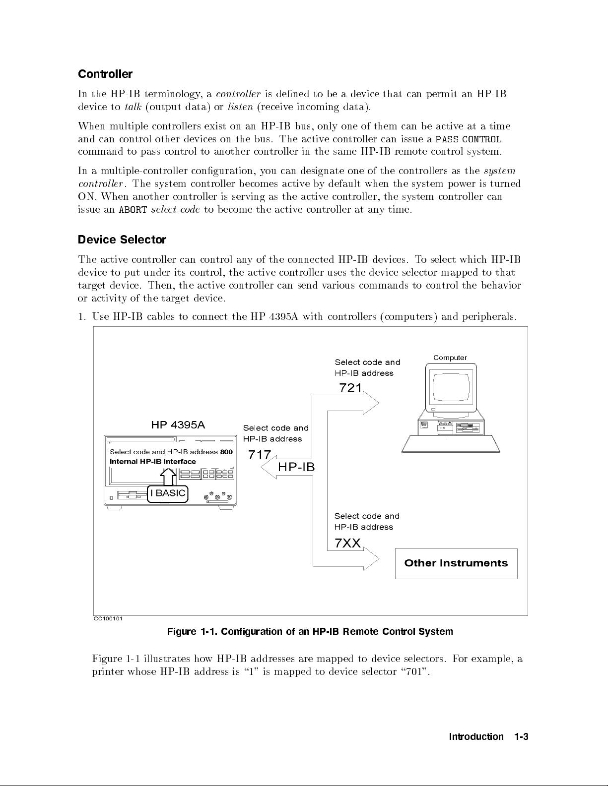
1. Use HP-IB cables to connect the HP 4395A with con
trollers (computers) and peripherals.
Figure 1-1. Configuration of an HP-IB Remote Control System
Figure 1-1 illustrates how HP-IB addresses are mapped to device selectors. For example, a
printer whose HP-IB address is \1" is mapp ed to device selector \701".
Introduction 1-3
Page 30

The HP Instrument BASIC feature is internally connected to the HP 4395A via the built-in
interface. The interface select co de for the built-in interface is dened as \8." Thus it is
distinguished from the external select code \7."
From HP Instrument BASIC, any address ranging from \00" to \30" can b e used to
designate the analyzer, which is only the device that is connected to the built-in interface.
Throughout this manual, the address \00" is always used for the analyzer so that its device
selecter is \800."
How large a system can you
congure?
maximum of 15 devices can be connected on one bus system.
The length of cable between one device and another must be less
than or equal to four meters. The total length of cable in one bus
system must be less than or equal to two meters timesthe number
of devices connected on the bus (the HP-IB controller counts as
one device). The total length of cable must not exceed 20 meters
Star, linear, and combinational cable congurations are allowed.
There must be no lo op.
It is recommended that no more than four piggybac
be stacked together on one device. Otherwise, the resulting
structure could exert enough force on the connector moun
damage it.
k connectors
ting to
1-4 Introduction
Page 31

Writing and Running Programs
Easy Program Writing
This section serves a simple programming example, which describ es procedures required to
write and run a program using HP Instrument BASIC. See Chapter 9 for general description
of the HP Instrument BASIC and its usage. You can also type in the program without using
the BASIC feature.
In this example, the HP 4395A is set to the condition shown below:
ACTIVE CHANNEL Block Channel 1 (Default)
MEASUREMENT Blo ck Network Analyzer
A/R
LOG MAGFormat (Default)
Display Scale : Auto
SWEEP Blo ck Center Frequency : 70MHz
Span Frequency : 100kHz
This example requires no keyborad operation;all the pro cedure can be done b
y pressing the
keys on the front panel.
1. Turn ON the HP 4395A
2. Press the key and softkeys as shown below to display the softkeys for the network
analyzer.
NNNNNNNNNNNNNNNNNNNNNNNNNNNNNNNNNNNNNNNNN
4
5
ANALYZER TYPE
Meas
NNNNNNNNNNNNNNNNNNNNNNNNNNNNNNNNNNNNNNNNNNNNNNNNNN
NETWORK ANALYZER
3. Press
4
System
NNNNNNNNNNNNNNNNNNNN
5
IBASIC
NNNNNNNNNNNNNN
Edit
The system go es to the edit mode. The cursor is lo cated at the line 10.
d a
10 _
4. Press
NNNNNNNNNNNNNNNNNNNNNNNNNNNNNNNNNNNNNNNNN
ASSIGN Hp4395
This brings the command b elow at the cursor.
d a
10 ASSIGN Hp4395 TO 800_
5. Press
4x15
Introduction 1-5
Page 32

This conrms the entry of a command and the cursor moves to the next line.
d a
10 ASSIGN Hp4395 TO 800
20 _
6. Press
NNNNNNNNNNNNNNNNNNNNNNNNNNNNNNNNNNNNNNNNN
OUTPUT Hp4395
You will see the following character strings on the screen:
d a
10 ASSIGN Hp4395 TO 800
20 OUTPUT Hp4395""
7. Press the key shown belowtoenter the preset command.
4
5
Preset
At the cursor displayed is the HP-IB command \
;PRES
" which presets an instrument.
d a
10 ASSIGN Hp4395 TO 800
20 OUTPUT Hp4395;";PRES"
Then press
Note
4
5
.
x1
If you place more than one command in a OUTPUT statemen
t, they should
be delimited using \;". The delimiter is automatically inserted when y
ou enter
HP-IB commands with the keys on the front panel.
8. Press the key and softkeys as shown below to specify the measurement parameter to A/R.
NNNNNNNNNNNNNNNNNNNNNNNNNNNNNNNNNNNNNNNNN
OUTPUT Hp4395
This generates the program co de as follo
NNNNNNNNNNNNNNNNNNNNNNNNNNNNNNNNNNNNNNNNN
4
5
ANALYZER TYPE
Meas
NNNNNNNNNNNNNNNNNNNNNNNNNNNNNNNNNNNNNNNNNNNNNNNNNN
NETWORK ANALYZER
ws:
NNNNNNNNNNNNNNNNNNNN
RETURN
NNNNNNNNNNN
A/R
d a
10 ASSIGN Hp4395 TO 800
20 OUTPUT Hp4395;";PRES "
30 OUTPUT Hp4395;";NA;MEAS AR"
Then press
4
5
.
x1
9. Press the key and softkeys as shown below to specify the center and span frequencies.
4
System
NNNNNNNNNNNNNNNNNNNN
5
IBASIC
NNNNNNNNNNNNNNNNNNNNNNNNNNNNNNNNNNNNNNNNN
OUTPUT Hp4395
4
Cent54754054M/
54
Span54154054054k/m54x1
5
1-6 Introduction
Page 33

d a
10 ASSIGN Hp4395 TO 800
20 OUTPUT Hp4395;";PRES"
30 OUTPUT Hp4395;";NA;MEAS AR"
40 OUTPUT Hp4395;";CENT 70E6;SPAN 100E3"
50 _
10. Press the key and softkeys as shown below to auto-scaling.
4
System
NNNNNNNNNNNNNNNNNNNN
5
IBASIC
NNNNNNNNNNNNNNNNNNNNNNNNNNNNNNNNNNNNNNNNN
OUTPUT Hp4395
4
Scale Ref
NNNNNNNNNNNNNNNNNNNNNNNNNNNNNNNN
5
AUTO SCALE
4x15
d a
10 ASSIGN Hp4395 TO 800
20 OUTPUT Hp4395;";PRES"
30 OUTPUT Hp4395;";NA;MEAS AR"
40 OUTPUT Hp4395;";CENT 70E6;SPAN 100E3"
50 OUTPUT Hp4395;";AUTO"
60 _
11. Enter END command to end the program.
4
System
NNNNNNNNNNNNNNNNNNNN
5
IBASIC
NNNNNNNNNNN
END
4
5
x1
d a
10 ASSIGN Hp4395 TO 800
20 OUTPUT Hp4395;";PRES"
30 OUTPUT Hp4395;";NA;MEAS AR"
40 OUTPUT Hp4395;";CENT 70E6;SPAN 100E3"
50 OUTPUT Hp4395;";AUTO"
60 END
70 _
12. Press the key below to exit the edit mode.
NNNNNNNNNNNNNNNNNNNNNNNNNN
END EDIT
The LCD switches back to the measurement results.
Note
HP Instrument BASIC cannot be used to program certain operations, suchas
the pro cedures for calibration.
Introduction 1-7
Page 34

Running (Executing) Programs
Press the following key and softkeys from the front panel to execute the program:
4
System
NNNNNNNNNNNNNNNNNNNN
5
IBASIC
NNNNNNNNNNN
Run
The system executes the program. You can execute the
RUN
statement from the keyboard.
Type and press as follows:
RUN
4
5
Enter
Saving Programs
Simple procedure for saving a program is shown here. See \Saving Programs (SAVE)" in
Chapter 9 for details.
1. Connect the keyboard to the HP 4395A
2. Press the keys and softkeys as shown below to switch the screen area alloation.
4
Display
NNNNNNNNNNNNNN
5
NNNNNNNNNNNNNNNNNNNNNNNNNNNNNNNNNNNNNNNNNNNNNNNNNNNNNNNN
MORE
DISPLAY ALLOCATION
NNNNNNNNNNNNNNNNNNNNNNNNNNNNN
ALL BAISC
3. Select the storage device where you wish to saveyour program.
4
System
NNNNNNNNNNNNNNNNNNNN
5
IBASIC
NNNNNNNNNNNNNN
MORE
NNNNNNNNNNNNNNNNN
MSI[]
4. In the key sequence above, choose [INTERNAL] to save the program on a oppy disk or
[MEMORY] on the memory disk.
5. Press the keys and softkeys as shown below.
4
System
NNNNNNNNNNNNNNNNNNNN
5
IBASIC
NNNNNNNNNNNNNN
MORE
NNNNNNNNNNNNNN
SAVE
This gives:
SAVE ""
6. From the keyboard, typ e in a le name you want to use. Note that the SAVE command
does not work if any le that has the same name already resides in the storage. In this
case, use a dierent name or overwrite the le with RE-SAVE command.
Retrieving a Program You Saved
1. Press the keys and softkeys as shown below to switch the screen area alloation.
4
Display
NNNNNNNNNNNNNN
5
NNNNNNNNNNNNNNNNNNNNNNNNNNNNNNNNNNNNNNNNNNNNNNNNNNNNNNNN
MORE
DISPLAY ALLOCATION
NNNNNNNNNNNNNNNNNNNNNNNNNNNNN
ALL BAISC
2. Select the storage device which stores the le you wish to retrieve.
4
System
NNNNNNNNNNNNNNNNNNNN
5
IBASIC
NNNNNNNNNNNNNN
MORE
NNNNNNNNNNNNNNNNN
MSI[]
3. Press
4
System
NNNNNNNNNNNNNNNNNNNN
5
IBASIC
NNNNNNNNNNNNNN
MORE
NNNNNNNNNNN
GET
4. From the keyboard, typ e in the le name.
5. Use CAT command to list the names of les, if y
ou are not certain an exact name of the
le.
1-8 Introduction
Page 35

Programming Measurement Sequence
This chapter provides basic pro cedures required for programming a measurement sequence.
The chaper covers:
HP-IB Commands Overview
To Program a Basic Measurement
HP-IB Commands Overview
All the analyzer's front-panel keys have a corresponding HP-IB command. By executing an
HP-IB command, you can operate the analyzer as if y
For example, Pressing
4
Preset
5
is the same as executing the HP-IB command,
ou were pressing the corresponding key.
PRES
.
Sending a HP-IB Command
2
Combine the BASIC
OUTPUT
statement with the HP-IB select co de, the device address, and
nally the analyzer command. For example, to execute
Using HP Instrument BASIC
And press
4
5
. The analyzer go es to the preset state.
Return
Using an External Controller
And press
4
5
. The analyzer is set to HP-IB remote mode. Then the analyzer goes to
Return
the preset state.
PRES
command, type:
Programming Measurement Sequence 2-1
Page 36

What is HP-IB remote
mode?
Executing an
OUTPUT
statement that is addressed to the analyzer,
sets it to the HP-IB remote mo de. In the remote mo de, all the
analyzer's front-panel keys are locked out, except
4
5
puts the analyzer back in local mo de. In lo cal mo de, all
Local
4
Local
5
. Pressing
front-panel keys are enabled.
Note
In the ab ove example, the OUTPUT statement can b e written as follows if
you use it with an ASSIGN statement:
ASSIGN @Hp4395 TO 800
OUTPUT @Hp4395;"PRES"
This style might make modication of a program easier, depending howyour
program is organized.
To Execute an HP-IB Command with a Parameter
Some HP-IB commands require a numeric parameter. For example:
OUTPUT @Hp4395;"CENT 25000000" ! Set center frequency to 25 MHz.
(The space b etween the command and the numeric parameter is mandatory.)
You can program it to be entered each time the program is run. For example:
100 INPUT "Enter center frequency(Hz).";F_cent
110 OUTPUT @Hp4395;"CENT ";F_cent
Executing this gives you:
d a
Enter center frequency (Hz).
25000000
The analyzer's center frequency is set to 25 MHz.
To Execute a Query
A query command is a command that inquires an instrument informations suchas
measurement data. In general, a query command is used in an OUTPUT statement with an
ENTER statement asso ciated. Note that executing a query command does not always result
in a single numerical value; it may contain multiple values or charater strings. See Chapter 11
for details.
10 OUTPUT @Hp4395;"CNTS?"
20 ENTER @Hp4395;A
Any HP-IB command that is used with a numeric parameter can also be used as query
command. For example, the
CENT
numeric parameter
command used in the previous example,
can be combined with a?, and used as a query command as follows,
10 OUTPUT @Hp4395;"CENT?"
20 ENTER @Hp4395;A
30 PRINT A
2-2 Programming Measurement Sequence
Page 37

A query command is used mostly in an OUTPUT statement followed by an ENTER
statement;the OUTPUT statement sends the query command to the HP 4395A and the
ENTER statement receive a return value from the analyzer.
The
CENT?
command returns the current center frequency, which is put intoA. Executing this
program results in the following:
d a
25000000
By interrogating the analyzer to determine the values of the start and stop frequencies, or the
center frequency and frequency span, the computer can keep track of the actual frequencies.
Programming Measurement Sequence 2-3
Page 38

To Program a Basic Measurement
This section describ es how to organize the commands into a measurement sequence.
Figure 2-1 shows a typical program ow for a measurement.
Figure 2-1. Program Flow
The following program p erforms the measurementow controlling the analyzer using HP-IB.
This guide shows program lists of sample programs for an external con
sample programs in this guide with HP Instrument BASIC, change the select co de from 7
to 8 and change the HP-IB address from 17 to 00 (that is, use 800 instead of 717).
d a
10 !
20 !Fig.2-2 Basic Measurement
30 !
40 ASSIGN @Hp4395 TO 717 ! When iBASIC is used, change "717" to "800".
50 !
60 OUTPUT @Hp4395;"PRES" ! Preset HP 4395A
70 OUTPUT @Hp4395;"CHAN1;NA;MEAS S21;FMT LOGM"
80 INPUT "Enter center frequency (Hz).",F_cent
90 INPUT "Enter frequency span (Hz).",F_span
100 OUTPUT @Hp4395;"CENT ";F_cent
110 OUTPUT @Hp4395;"SPAN ";F_span
120 !
130 ! Frequency Response Calibration
140 OUTPUT @Hp4395;"CALK N50" ! Select 50 ohm type-N Cal. kit
150 OUTPUT @Hp4395;"CALI RESP" ! Select Response cal.
160 OUTPUT @Hp4395;"CLES" ! Clear all status
170 INPUT "Connect THRU, then press [Enter].",Dum$
180 OUTPUT @Hp4395;"*SRE 4;ESNB 1" ! Set enable STB and ESB
troller. To use the
Figure 2-2. Sample Program : Basic Measurement (1/2)
2-4 Programming Measurement Sequence
Page 39

190 ON INTR 7 GOTO Cal_end ! \ When iBASIC is used, change "7" to "8".
200 ENABLE INTR 7;2 !/
210 OUTPUT @Hp4395;"STANC" ! Measure THRU
220 Calibrating: GOTO Calibrating
230 Cal_end: !
240 OUTPUT @Hp4395;"RESPDONE" ! Calculating cal coefficients
250 OUTPUT @Hp4395;"*OPC?" ! \ Waiting calculation end
260 ENTER @Hp4395;Dum !/
270 DISP "Response cal completed."
280 !
290 ! Measurement
300 INPUT "Connect DUT, then press [Enter].",Dum$
310 OUTPUT @Hp4395;"CLES" ! Clear all status registers
320 OUTPUT @Hp4395;"*SRE 4;ESNB 1"
330 ON INTR 7 GOTO Sweep_end ! \ When iBASIC is used,
340 ENABLE INTR 7;2 ! / change "7" to "8"
350 OUTPUT @Hp4395;"SING" ! Sweep mode is SINGLE
360 Measuring: GOTO Measuring
370 Sweep_end: !
380 OUTPUT @Hp4395;"MKR ON" ! Marker 1 ON
390 OUTPUT @Hp4395;"SEAM MAX" ! Search MAX
400 OUTPUT @Hp4395;"OUTPMKR?" ! Output marker value
410 ENTER @Hp4395;Val1,Val2,Swp
420 PRINT "Max val:",Val1;"dB"
430 PRINT "Swp.Prmtr:",Swp;"Hz"
440 END
c b
Figure 1-3. Sample Program : Basic Measurement (2/2)
Set I/O Path
40 ASSIGN @Hp4395 TO 717 ! When iBASIC is used, change "717" to "800".
This operation allows you to use
@Hp4395
, instead of
717
(or
800
), as the HP-IB address in the
program.
Set Up the Measurement Parameters
60 OUTPUT @Hp4395;"PRES"
70 OUTPUT @Hp4395;"CHAN1;NA;MEAS S21;FMT LOGM"
80 INPUT "Enter center frequency (Hz).",F_cent
90 INPUT "Enter frequency span (Hz).",F_span
100 OUTPUT @Hp4395;"CENT ";F_cent
110 OUTPUT @Hp4395;"SPAN ";F_span
You can execute HP-IB commands in the same sequence as key op eration. Lines 60
and 70 p erform the same op eration as pressing
NNNNNNNNNNNNNNNNNNNNNNNNNNNNNNNNNNNNNNNNNNNNNNNNNN
NETWORK ANALYZER
NNNNNNNNNNNNNNNNNNNNNNNNNNNNNNNNNNNNNN
S PARAMETERS
NNNNNNNNNNNNNNNNNNNNNNNNNNNNNNNNNNNNNNNNNNNNNNNNNNNNNNNN
Trans:FDW S21[B/R]
4
Preset54Chan 154Meas
4
Format
NNNNNNNNNNNNNNNNNNNNNNNNNNNNNNNNNNNNNNNNN
5
ANALYZER TYPE
NNNNNNNNNNNNNNNNNNNNNNN
5
LOG MAG
.
In general, the procedure for setting up measurements on the analyzer via HP-IB follows the
same sequence as performing the pro cedure manually. There is no required order, as long as
the desired frequency range, number of points, and power level are set before performing the
calibration.
In line 70, several HP-IB commands, separated by semicolon, are executed in a line. This is
the same as:
Programming Measurement Sequence 2-5
Page 40

70 OUTPUT @Hp4395;"CHAN1"
71 OUTPUT @Hp4395;"NA"
72 OUTPUT @Hp4395;"MEAS S21"
73 OUTPUT @Hp4395;"FMT LOGM"
In lines 80 to 110 (setting frequency), parameters are required with the HP-IB command. To
set parameters, see \To Execute an HP-IB Command with a Parameter" later in this chapter.
Perform Calibration
130 ! Frequency Response Calibration
140 OUTPUT @Hp4395;"CALK N50" ! Select 50 ohm type-N Cal. kit
150 OUTPUT @Hp4395;"CALI RESP" ! Select Response cal.
160 OUTPUT @Hp4395;"CLES" ! Clear all status
170 INPUT "Connect THRU, then press [Return].",Dum$
180 OUTPUT @Hp4395;"*SRE 4;ESNB 1" ! Set enable STB and ESB
190 ON INTR 7 GOTO Cal_end ! \ When iBASIC is used, change "7" to "8".
200 ENABLE INTR 7;2 !/
210 OUTPUT @Hp4395;"STANC" ! Measure THRU
220 Calibrating: GOTO Calibrating
230 Cal_end: !
240 OUTPUT @Hp4395;"RESPDONE" ! Calculating cal coefficients
250 OUTPUT @Hp4395;"*OPC?" ! \ Waiting calculation end
260 ENTER @Hp4395;Dum !/
270 DISP "Response cal completed."
In lines 140 to 240, the HP-IB program follo
ws the key strokes required to calibrate from the
front panel. This program performs a response calibration.
Line 170 requests the operator to connect a THR
U calibration standard.
Lines 180 through 220 use the status bytes to detect the completion of the THRU calibration.
See \ToWait for Sweep End" in Chapter 5.
All the setting and calibration procedures are completed. No
wyou can start measuring your
DUT.
Connect DUT
300 INPUT "Connect DUT, then press [Enter].",Dum$
Line 300 requests the operator to connect a DUT to the analyzer.
Trigger a Measurement
310 OUTPUT @Hp4395;"CLES" ! Clear all status registers
320 OUTPUT @Hp4395;"*SRE 4;ESNB 1"
330 ON INTR 7 GOTO Sweep_end ! \ When iBASIC is used,
340 ENABLE INTR 7;2 ! / change "7" to "8"
350 OUTPUT @Hp4395;"SING" ! Sweep mode is SINGLE
360 Measuring: GOTO Measuring
370 Sweep_end: !
Lines 310 to 370 enable SRQinterruption for sweep end detection. For details, see \ToWait
for Sweep End" in Chapter 5.
2-6 Programming Measurement Sequence
Page 41

In line 350, the analyzer executed a single trigger. For more advanced trigger control, see
Chapter 6.
Post-Processing
380 OUTPUT @Hp4395;"MKR ON" ! Marker 1 ON
390 OUTPUT @Hp4395;"SEAM MAX" ! Search MAX
Line 380 activates the marker and line 390 moves the marker to the maximum value on the
trace. For details on using the marker, see Chapter 3.
Transfer Data
400 OUTPUT @Hp4395;"OUTPMKR?" ! Output marker value
410 ENTER @Hp4395;Val1,Val2,Swp
The measured data is transferred to the controller. For details about data transfer, see
Chapter 3.
Programming Measurement Sequence 2-7
Page 42

Page 43
3
Processing and Tranferring Data
This chapter illustrates how to transfer and receive data stored in the HP 4395A between the
controller via HP-IB.
Measurement data can be read out of the analyzer in the following ways:
1. The entire trace (or data for a specied number of p oints) can be read out in the following
ways:
Data arrays | In regard to the data processing ow, the following data arrays are
available.
RAWDATA ARRAYS
CALIBRATION COEFFICIENT ARRAYS
DATA ARRAYS
MEMORY ARRAYS
DATA TRACE ARRAYS
MEMORY TRACE ARRAYS
Note
When you transfer these data to HP 4395A, set HP 4395A's conguration
the same way as when you received data. Without this, you will be unable
to measure correct data. Be sure to set up CALIBRA
TION COEFFICIENT
ARRAYS.
Data format | The analyzer provides four data transfer formats.
FORM2 IEEE 32 bit oating point format
FORM3 IEEE 64 bit oating point format
FORM4 ASCII format
R
FORM5 MS-DOS
personal computer format
Depending on the format, the data transfer sp eed and the number of digits are changed.
Generally, binary data transfer (FORM2, FORM3, or FORM5) is faster than ASCI I
(FORM4).
2. Data can b e read o the trace selectiv
ely using the markers.
The presentvalue of the marker (real-imaginary data and sweep parameter) is retrieved.
For additional information on the marker functions, see Chapter 8.
Processing and Tranferring Data 3-1
Page 44
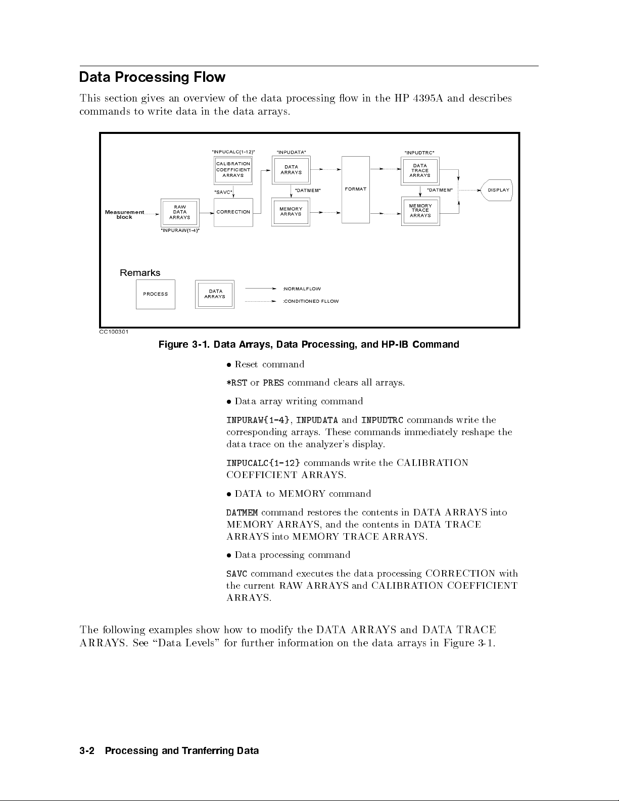
Data Processing Flow
This section gives an overview of the data processing ow in the HP 4395A and describes
commands to write data in the data arrays.
Figure 3-1. Data Arrays, Data Processing, and HP-IB Command
Reset command
*RSTorPRES
Data array writing command
INPURAW{1-4},INPUDATA
command clears all arrays.
and
INPUDTRC
commands write the
corresponding arrays. These commands immediately reshape the
data trace on the analyzer's display.
INPUCALC{1-12}
commands write the CALIBRATION
COEFFICIENT ARRAYS.
DATA to MEMORY command
DATMEM
command restores the contents in DATA ARRAYS into
MEMORY ARRAYS, and the contents in DATA TRACE
ARRAYS into MEMORY TRACE ARRAYS.
Data processing command
SAVC
command executes the data pro cessing CORRECTION with
the currentRAW ARRAYS and CALIBRATION COEFFICIENT
ARRAYS.
The following examples showhow to mo dify the DATA ARRAYS and DATA TRACE
ARRAYS. See \Data Levels" for further information on the data arrays in Figure 3-1.
3-2 Processing and Tranferring Data
Page 45

To Modify Calibration Data
d a
10 !
20 !Fig.3-2 To Modify Calibration Data
30 !
40 ASSIGN @Hp4395 TO 717 ! When iBASIC is used, change "717" to "800"
50 !
60 OUTPUT @Hp4395;"PRES"
70 OUTPUT @Hp4395;"NA"
80 INPUT "Enter center frequency(Hz).",F_cent
90 INPUT "Enter frequency span(Hz).",F_span
100 OUTPUT @Hp4395;"CENT ";F_cent
110 OUTPUT @Hp4395;"SPAN ";F_span
120 OUTPUT @Hp4395;"HOLD"
130 !
140 ! Calibration
150 OUTPUT @Hp4395;"CLES"
160 OUTPUT @Hp4395;"*SRE 4;ESNB 1" ! Set enable STB and ESB
170 INPUT "Connect THRU and press [RETURN] to do CAL.",Dum$
180 OUTPUT @Hp4395;"CALI RESP"
190 ON INTR 7 GOTO Cal_end ! \ When iBASIC is used,
200 ENABLE INTR 7;2 ! / change "7" to "8"
210 OUTPUT @Hp4395;"STANC" ! Measure THRU
220 Calibrating:GOTO Calibrating
230 Cal_end: !
240 OUTPUT @Hp4395;"RESPDONE" ! Calculating cal coefficient
250 OUTPUT @Hp4395;"*OPC?" ! \ Wait until calculating ends
260 ENTER @Hp4395;Dum !/
270 DISP "Calibration Complete"
280 !
290 ! Read Calibration Data
300 DIM Dat(1:801,1:2) ! When iBASIC is used, change "801" to "802"
310 OUTPUT @Hp4395;"POIN?" !\
320 ENTER @Hp4395;Nop ! | When iBASIC is used,delete these lines
330 REDIM Dat(1:Nop,1:2) !/
340 ASSIGN @Dt TO 717;FORMAT OFF ! When iBASIC is used,
350 OUTPUT @Hp4395;"FORM3" ! change "717" to "800"
360 OUTPUT @Hp4395;"OUTPCALC1?"
370 ENTER @Dt USING "%,8A";Head$
380 ENTER @Dt;Dat(*)
390 ENTER @Dt USING "%,1A";Dum$ ! When iBASIC is used, delete this line
400 !
410 ! Modify Calibration Data
420 !
430 ! Restore Calibration Data
440 OUTPUT @Hp4395;"INPUCALC1 ";
450 OUTPUT @Dt USING "#,8A";Head$
460 OUTPUT @Dt;Dat(*),END
470 ASSIGN @Dt TO *
480 OUTPUT @Hp4395;"SAVC" ! Redraw Trace
490 END
c b
Figure 3-2. Sample Program : To Modify Calibration Data
This program measures calibration standards, reads the obtained calibration data, and
restores the data in the analyzer.
Processing and Tranferring Data 3-3
Page 46

Read Error-Corrected Data
290 ! Read Calibration Data
300 DIM Dat(1:801,1:2) ! When iBASIC is used, change "801" to "802"
310 OUTPUT @Hp4395;"POIN?"
320 ENTER @Hp4395;Nop
330 REDIM Dat(1:Nop,1:2) ! | When iBASIC is used, delete these lines
340 ASSIGN @Dt TO 717;FORMAT OFF
350 OUTPUT @Hp4395;"FORM3"
360 OUTPUT @Hp4395;"OUTPCALC1?"
370 ENTER @Dt USING "%,8A";Head$
380 ENTER @Dt;Dat(*)
390 ENTER @Dt USING "%,1A";Dum$ ! | When iBASIC is used, delete these lines
The controller can read out the error co ecients using the HP-IB commands
12}
. Each point is a real/imaginary pair, and the number of points in the array is the same as
OUTPCALC{1-
the number of p oints in the sweep. For details on data transfer, see Chapter 3.
Each calibration type uses only as many arrays as needed, starting with array 1, and each
array stores a specic error coecient. Therefore, it is necessary to know the type of
calibration about to b e read out: attempting to read an array not being used in the curren
t
calibration causes the \REQUESTED DATA NOT CURRENTLYAVAILABLE" warning to
be displayed. For assignment of data arrays, see \Calibration Types and Standard Classes,
and Calibration Arrays" in this chapter.
Modify Calibration Data
400 !
410 ! Modify Calibration Data
420 !
In this portion of program, you mo dify the CALIBRATION COEFFICIENT ARRAY, which
is contained in
Dat(1:801,1:2)
.
Restore Modified Calibration Data
430 ! Restore Calibration Data
440 OUTPUT @Hp4395;"INPUCALC1 ";
450 OUTPUT @Dt USING "#,8A";Head$
460 OUTPUT @Dt;Dat(*),END
Line 440 op ens the CALIBRATION COEFFICIENT ARRAY 1 in the analyzer. This array is
used to restore the data.
Lines 450 and 460 send the le header (
(
END
). The le header is an input in line 370.
), calibration data (
Dat(*)
) and the terminator
Head$
This example sets the trigger to HOLD at line 120. The analyzer do es not redraw the trace
with the new CALIBRATION COEFFICIENT ARRAYS when the trigger is set to HOLD.
You can redraw the trace by issuing the HP-IB command
SAVC
.
3-4 Processing and Tranferring Data
Page 47

To Modify Error-Corrected Data
d a
10 !
20 !Fig.3-3 To Modify Error-Corrected Data
30 !
40 ASSIGN @Hp4395 TO 717 ! When iBASIC is used, change "717" to "800"
50 !
60 OUTPUT @Hp4395;"PRES"
70 OUTPUT @Hp4395;"NA"
80 INPUT "Enter center frequency(Hz).",F_cent
90 INPUT "Enter frequency span(Hz).",F_span
100 OUTPUT @Hp4395;"CENT ";F_cent
110 OUTPUT @Hp4395;"SPAN ";F_span
120 !
130 INPUT "Connect DUT and press [RETURN].",Dum$
140 OUTPUT @Hp4395;"CLES"
150 OUTPUT @Hp4395;"*SRE 4;ESNB 1" ! Set enable STB and ESB
160 ON INTR 7 GOTO Sweep_end ! \ When iBASIC is used,
170 ENABLE INTR 7;2 ! / change "7" to "8"
180 OUTPUT @Hp4395;"SING"
190 Measuring: GOTO Measuring
200 Sweep_end: !
210 DISP "Measurement Complete"
220 !
230 ! Read Error-Corrected Data
240 DIM Dat(1:801,1:2) ! When iBASIC is used, change "801" to "802"
250 OUTPUT @Hp4395;"POIN?" !\
260 ENTER @Hp4395;Nop ! | When iBASIC is used, delete these lines
270 REDIM Dat(1:Nop,1:2) !/
280 ASSIGN @Dt TO 717;FORMAT OFF ! When iBASIC is used,
290 OUTPUT @Hp4395;"FORM3" ! change "717" to "800"
300 OUTPUT @Hp4395;"OUTPDATA?"
310 ENTER @Dt USING "%,8A";Head$
320 ENTER @Dt;Dat(*)
330 ENTER @Dt USING "%,1A";Dum$ ! When iBASIC is used, delete this line
340 !
350 ! Modify Error-Corrected Data
360 !
370 ! Restore Error-Corrected Data
380 OUTPUT @Hp4395;"INPUDATA ";
390 OUTPUT @Dt USING "#,8A";Head$
400 OUTPUT @Dt;Dat(*),END
410 ASSIGN @Dt TO *
420 END
c b
Figure 3-3. Sample Program : To Modify Error-Corrected Data
This program measures the DUT, reads the obtained data, and restores the data in the
analyzer.
Processing and Tranferring Data 3-5
Page 48
Read Error-Corrected Data
230 ! Read Error-Corrected Data
240 DIM Dat(1:801,1:2) ! When iBASIC is used, change "801" to "802"
250 OUTPUT @Hp4395;"POIN?" !\
260 ENTER @Hp4395;Nop ! | When iBASIC is used, delete these lines
270 REDIM Dat(1:Nop,1:2) !/
280 ASSIGN @Dt TO 717;FORMAT OFF ! When iBASIC is used,
290 OUTPUT @Hp4395;"FORM3" ! change "717" to "800"
300 OUTPUT @Hp4395;"OUTPDATA?"
310 ENTER @Dt USING "%,8A";Head$
320 ENTER @Dt;Dat(*)
330 ENTER @Dt USING "%,1A";Dum$ ! When iBASIC is used, delete this line
OUTPDATA?
Restore Modified Error-Corrected Data
370 ! Restore Error-Corrected Data
380 OUTPUT @Hp4395;"INPUDATA ";
390 OUTPUT @Dt USING "#,8A";Head$
400 OUTPUT @Dt;Dat(*),END
Line 380 op ens the DATA ARRAYS in the analyzer to restore the data.
Lines 390 to 400 transfer data in FORM3 (a similar procedure is used in the \T
Calibration Data" example).
command retrieves DATA ARRAYS in the analyzer.
o Modify
3-6 Processing and Tranferring Data
Page 49

To Modify Trace Data
d a
10 !
20 !Fig.3-4 To Modify Trace Data
30 !
40 ASSIGN @Hp4395 TO 717 ! When iBASIC is used, change "717" to "800"
50 !
60 OUTPUT @Hp4395;"PRES"
70 OUTPUT @Hp4395;"NA"
80 INPUT "Enter center frequency(Hz).",F_cent
90 INPUT "Enter frequency span(Hz).",F_span
100 OUTPUT @Hp4395;"CENT ";F_cent
110 OUTPUT @Hp4395;"SPAN ";F_span
120 !
130 INPUT "Connect DUT and press [RETURN].",Dum$
140 OUTPUT @Hp4395;"CLES"
150 OUTPUT @Hp4395;"*SRE 4;ESNB 1" ! Set enable STB and ESB
160 ON INTR 7 GOTO Sweep_end ! \ When iBASIC is used,
170 ENABLE INTR 7;2 ! / change "7" to "8"
180 OUTPUT @Hp4395;"SING"
190 Measuring: GOTO Measuring
200 Sweep_end: !
210 DISP "Measurement Complete"
220 !
230 ! Read Trace Data
240 DIM Dat(1:801,1:2) ! When iBASIC is used, change "801" to "802"
250 OUTPUT @Hp4395;"POIN?" !\
260 ENTER @Hp4395;Nop ! | When iBASIC is used, delete these lines
270 REDIM Dat(1:Nop,1:2) !/
280 ASSIGN @Dt TO 717;FORMAT OFF ! When iBASIC is used,
290 OUTPUT @Hp4395;"FORM3" ! change "717" to "800"
300 OUTPUT @Hp4395;"OUTPDTRC?"
310 ENTER @Dt USING "%,8A";Head$
320 ENTER @Dt;Dat(*)
330 ENTER @Dt USING "%,1A";Dum$ ! When iBASIC is used, delete this line
340 !
350 ! Modify Trace Data
360 !
370 ! Restore Trace Data
380 OUTPUT @Hp4395;"INPUDTRC ";
390 OUTPUT @Dt USING "#,8A";Head$
400 OUTPUT @Dt;Dat(*),END
410 ASSIGN @Dt TO *
420 END
c b
Figure 3-4. Sample Program : To Modify Trace Data
This program measures the DUT, reads the obtained data, and restores the data into the
analyzer. For details on how to read the data array, see Chapter 3.
For details on how to mo dify the trace on the display, see the \To Mo dify Calibration Data"
example.
Processing and Tranferring Data 3-7
Page 50

Read Trace Data
230 ! Read Trace Data
240 DIM Dat(1:801,1:2) ! When iBASIC is used, change "801" to "802"
250 OUTPUT @Hp4395;"POIN?" !\
260 ENTER @Hp4395;Nop ! | When iBASIC is used, delete these lines
270 REDIM Dat(1:Nop,1:2) !/
280 ASSIGN @Dt TO 717;FORMAT OFF ! When iBASIC is used,
290 OUTPUT @Hp4395;"FORM3" ! change "717" to "800"
300 OUTPUT @Hp4395;"OUTPDTRC?"
310 ENTER @Dt USING "%,8A";Head$
320 ENTER @Dt;Dat(*)
330 ENTER @Dt USING "%,1A";Dum$ ! When iBASIC is used, delete this line
The
OUTPDTRC?
transfer, see \To Get Measurement Data Using ASCI I Format" and Figure 3-6.
Restore Modified Trace Data
370 ! Restore Trace Data
380 OUTPUT @Hp4395;"INPUDTRC ";
390 OUTPUT @Dt USING "#,8A";Head$
400 OUTPUT @Dt;Dat(*),END
command (line 300) retrieves trace data in the analyzer. For details on data
Line 380 op ens the DATA TRACE ARRAYS in the analyzer to restore the data.
Lines 390 and 400 transfer data in FORM3 (a similar procedure is used in the \T
Calibration Data" example).
o Mo dify
3-8 Processing and Tranferring Data
Page 51

To Get Measurement Data Using ASCII Format
This section provides pro cedures required for getting data using ASCII format, taking a
measurement trace as an example.
d a
10 !
20 !Fig.3-5 To Get Measurement Trace Using ASCII Format
30 !
40 ASSIGN @Hp4395 TO 717 ! When iBASIC is used, change "717" to "800"
50 !
60 INPUT "ENTER CENTER FREQUENCY (Hz)",F_cent
70 INPUT "ENTER FREQUENCY SPAN (Hz)",F_span
80 OUTPUT @Hp4395;"CENT";F_cent
90 OUTPUT @Hp4395;"SPAN";F_span
100 !
110 OUTPUT @Hp4395;"CLES"
120 OUTPUT @Hp4395;"*SRE 4;ESNB 1"
130 ON INTR 7 GOTO Sweep_end ! \ When iBASIC is used, change "7" to "8"
140 ENABLE INTR 7;2 !/
150 OUTPUT @Hp4395;"SING" ! Trigger a Measurement
160 Measuring: GOTO Measuring ! Measuring
170 Sweep_end: !
180 DIM Dat(1:801,1:2),Swp(1:801) ! For spectrum measurement, change
190 OUTPUT @Hp4395;"FORM4" ! "Dat(1:801,1:2)" to "Dat(1:801)"
200 OUTPUT @Hp4395;"OUTPDTRC?"
210 ENTER @Hp4395 USING "%,K";Dat(*)
220 OUTPUT @Hp4395;"OUTPSWPRM?"
230 ENTER @Hp4395 USING "%,K";Swp(*)
240 !
250 OUTPUT @Hp4395;"POIN?"
260 ENTER @Hp4395;Nop
270 FOR I=1 TO Nop
280 PRINT Swp(I);"Hz",Dat(I,1);"dB" ! For spectrum measurement, change
290 NEXT I ! "Dat(I,1)" to "Dat(I)"
300 END
c b
Figure 3-5. Sample Program : To Get Measurement Trace Using ASCII Format
Set the Receive Array
180 DIM Dat(1:801,1:2),Swp(1:801)
Line 180 sets the array size to the analyzer's maximum number of measurement points (801).
In this example, it is assumed that the analyzer is in the network analyzer mo de of operation,
in which each point has complex data. If you use the analyzer in the sp ectrum analyzer mode,
each measurement p oint has only real data, so you must set the data array
Dat
as follows:
180 DIM Dat(1:801),Swp(1:801)
280 PRINT Swp(I);"Hz",Dat(I);"dB"
If the number of measurement points changes, then so does the number of data. You must
control the number of entered measurement data (see lines 210 and 230).
Processing and Tranferring Data 3-9
Page 52

Set Data Transfer Format
190 OUTPUT @Hp4395;"FORM4"
Line 190 tells the analyzer to use the ASCI I transfer format.
Read Data
200 OUTPUT @Hp4395;"OUTPDTRC?"
210 ENTER @Hp4395 USING "%,K";Dat(*)
220 OUTPUT @Hp4395;"OUTPSWPRM?"
230 ENTER @Hp4395 USING "%,K";Swp(*)
OUTPDTRC?
In line 210 and 230, you must choose
retrieves DATA TRACE ARRAYS, and
%,K
to allow for an insucientnumber of data points to
ll the array (which is 801 as declared in line 180).
What are other data
arrays?
You can retrieve the following data arrays, exchanging HP-IB
command
OUTPDTRC?
see Chapter 11.
RAWDATA ARRAYS
DATA ARRAYS
MEMORY ARRAYS
MEMORY TRACE ARRAYS
CALIBRATION COEFFICIENT
ARRAYS
OUTPSWPRM?
retrieves sweep parameters.
in line 200. For details on each command,
OUTPRAW{1-4}?
OUTPDATA?
OUTPMEMO?
OUTPMTRC?
OUTPCALC{1-12}?
3-10 Processing and Tranferring Data
Page 53

To Get Measurement Trace Using Binary Format
This section provides pro cedures required for getting data using binary format, taking a
measurement trace as an example.
Before running the program in Figure 3-6 , you must mo dify the dimension of the data arrays
to match to the analyzer typ e (network or spectrum). (See the \Set the Receive Array"
example.)
d a
10 !
20 !Fig.3-6 To Get Measurement Trace Using
30 ! IEEE 64-bit Floating point Format (For External Controller)
40 !
50 ASSIGN @Hp4395 TO 717
60 !
70 INPUT "ENTER CENTER FREQUENCY (Hz)",F_cent
80 INPUT "ENTER FREQUENCY SPAN (Hz)",F_span
90 OUTPUT @Hp4395;"CENT";F_cent
100 OUTPUT @Hp4395;"SPAN";F_span
110 !
120 OUTPUT @Hp4395;"CLES"
130 OUTPUT @Hp4395;"*SRE 4;ESNB 1"
140 ON INTR 7 GOTO Sweep_end !
150 ENABLE INTR 7;2 !
160 OUTPUT @Hp4395;"SING"
170 Measuring:GOTO Measuring
180 Sweep_end: !
190 DIM Dat(1:801,1:2),Swp(1:801) ! For spectrum measurement, change
200 OUTPUT @Hp4395;"POIN?" ! "Dat(1:801,1:2)" to "Dat(1:801)"
210 ENTER @Hp4395;Nop
220 REDIM Dat(1:Nop,1:2),Swp(1:Nop)
230 OUTPUT @Hp4395;"FORM3"
240 ASSIGN @Dt TO 717;FORMAT OFF
250 OUTPUT @Hp4395;"OUTPDTRC?"
260 ENTER @Dt USING "%,8A";A$
270 ENTER @Dt;Dat(*)
280 ENTER @Dt USING "%,1A";B$
290 OUTPUT @Hp4395;"OUTPSWPRM?"
300 ENTER @Dt USING "%,8A";A$
310 ENTER @Dt;Swp(*)
320 ENTER @Dt USING "%,1A";B$
330 ASSIGN @Dt TO *
340 !
350 FOR I=1 TO Nop
360 PRINT Swp(I);"Hz",Dat(I,1);"dB" ! For spectrum measurement, change
370 NEXT I ! "Dat(I,1)" to "Dat(I)"
380 END
c b
Figure 3-6.
Sample Program : To Get Measurement Trace Using IEEE 64-bit Floating Point Format (For
External Controller)
This program is similar to the ASCII transfer program. However, you must set the data
transfer format OFF when using the binary data transfer format.
Processing and Tranferring Data 3-11
Page 54

Set the Receive Array
190 DIM Dat(1:801,1:2),Swp(1:801)
200 OUTPUT @Hp4395;"POIN?"
210 ENTER @Hp4395;Nop
220 REDIM Dat(1:Nop,1:2),Swp(1:Nop)
Line 190 sets the array size to the analyzer's maximum number of measurement points (801).
In this example, it is assumed that the analyzer is in the network analyzer mo de of operation,
in which each point has complex data. If you use the analyzer in the spectrum analyzer mode,
each measurement p oint has only real data, so you must set the data array
Dat
as follows:
190 DIM Dat(1:801),Swp(1:801)
220 REDIM Dat(1:Nop),Swp(1:Nop)
360 PRINT Swp(I);"Hz",Dat(I);"dB"
Lines 200 and 210 interrogate the analyzer to determine the number of measurement p oints.
Line 220 resizes the receive array to match the data.
Set Data Transfer Format
200 OUTPUT @Hp4395;"FORM3"
210 ASSIGN @Dt TO 717;FORMAT OFF
To use FORM3 the computer must be instructed to stop formatting the incoming data with
the
ENTER
statement. This is done by dening an I/O path with ASCII formatting OFF. The
I/O path p oints to the analyzer. This path can be used to read or write data to the analyzer,
as long as that data is in binary rather than ASCII format.
What are other binary data
formats?
You can use the following data transfer formats, bychanging the
HP-IB command
IEEE 32 bit oating point format
MS-DOS
FORM3
in line 200.
R
personal computer format
FORM2
FORM5
Read Data
250 OUTPUT @Hp4395;"OUTPDTRC?"
260 ENTER @Dt USING "%,8A";A$
270 ENTER @Dt;Dat(*)
280 ENTER @Dt USING "%,1A";B$
290 OUTPUT @Hp4395;"OUTPSWPRM?"
300 ENTER @Dt USING "%,8A";A$
310 ENTER @Dt;Swp(*)
320 ENTER @Dt USING "%,1A";B$
FORM3 has an eight-byte header to deal with. The rst twobytes are the ASCII characters
#6. This indicates that a xed length block transfer follows and that the next 6 bytes form an
integer specifying the number of bytes in the block to follow. The header must be read in so
that data order is maintained (lines 260 and 300).
At the data end, the terminator \lf^
3-12 Processing and Tranferring Data
eoi
" is sent(lines 280 and 320).
Page 55
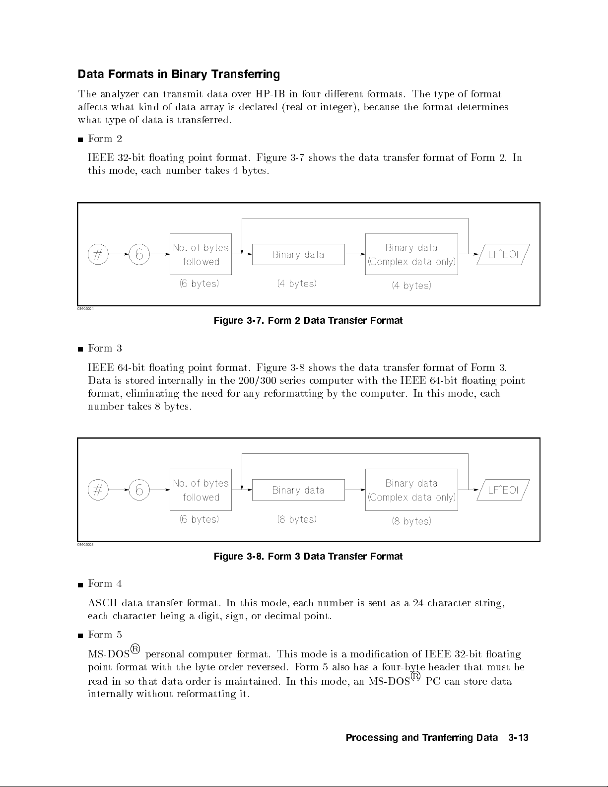
Data Formats in Binary Transferring
The analyzer can transmit data over HP-IB in four dierent formats. The type of format
aects what kind of data array is declared (real or integer), b ecause the format determines
what type of data is transferred.
Form 2
IEEE 32-bit oating point format. Figure 3-7 shows the data transfer format of Form 2. In
this mo de, eachnumber takes 4 bytes.
Figure 3-7. Form 2 Data Transfer Format
Form 3
IEEE 64-bit oating point format. Figure 3-8 shows the data transfer format of Form 3.
Data is stored internally in the 200/300 series computer with the IEEE 64-bit oating p oin
format, eliminating the need for any reformatting by the computer. In this mo de, each
number takes 8 bytes.
Figure 3-8. Form 3 Data Transfer Format
Form 4
ASCII data transfer format. In this mo de, eachnumber is sent as a 24-character string,
eachcharacter being a digit, sign, or decimal point.
Form 5
R
MS-DOS
point format with the byte order reversed. Form 5 also has a four-byte header that must be
read in so that data order is maintained. In this mo de, an MS-DOS
internally without reformatting it.
personal computer format. This mo de is a modication of IEEE 32-bit oating
R
PC can store data
t
Processing and Tranferring Data 3-13
Page 56

File Headers
When using the binary data transfer format, the transferred data must be accompanied by
the le header that represents the data length. In this example, the data transfer format is
FORM3 and the transferred data is congured as follows:
Figure 3-9. FORM3 Data Transfer Format
If you are not reading the header, you can create it using the number of data points. Change
the program lines 440 to 460 as follows:
440 OUTPUT @Hp4395;"POIN?"
441 ENTER @Hp4395;Nop
442 V$=VAL$(Nop*2*8)
443 Numv=LEN(V$)
444 Head$="000000"
445 FOR I=1 TO Numv
446 Head$[7-I,7-I]=V$[Numv-I+1,Numv-I+1]
447 NEXT I
448 !
449 OUTPUT @Hp4395;"INPUCALC1 ";
450 OUTPUT @Dt USING "#,8A";"#6"&Head$
460 OUTPUT @Dt;Dat(*),END
Lines 440 to 442 calculate the number of bytes transferred (8 byte for real part, 8 byte for
imaginary part), and represents it in the string format.
Line 443 counts the number of characters in the string that contains the number of bytes
transferred.
Line 444 enters 0 as the initial value in all header arrays.
Lines 445 to 447 place the number of bytes transferred to the header array digit by digit from
the sixth array to the rst arra
For example, if the number of points is 201, the value of
y of the header.
Head$is003216
.
3-14 Processing and Tranferring Data
Page 57

Saving a Data File
This section explains howtosave data from the HP 4395A to a storage device. All examples
contained herein assume that you intend to output measurement data from the HP 4395A
upon completion of a measurement and then save the data on a oppy disk.
If you wish to use the following sample program with Instrument BASIC, specify in advance a
memory disk or oppy disk drive as the target storage device.
d a
10 DIM Dat(1:802,1:2)
20 ASSIGN @Hp4395 TO 717
40 OUTPUT @Hp4395;"POIN?"
50 ENTER @Hp4395;Nop
60 REDIM Dat(1:Nop,1:2)
70 OUTPUT @Hp4395;"FORM4"
80 OUTPUT @Hp4395;"OUTPDTRC?"
90 ENTER @Hp4395;Dat(*)
100 !
110 !
120 Fname$="data01"
130 PURGE Fname$
140 CREATE Fname$,1
150 ASSIGN @F TO Fname$;FORMAT ON
160 OUTPUT @F;Dat(*)
170 ASSIGN @F TO *
180 !
190 END
c b
Figure 3-10. Saving Data on a Floppy Disk
Creating a File to Contain the Data
120 Fname$="data01"
130 PURGE Fname$
140 CREATE Fname$,1
The above code creates a le named
named
data01
.
data01
. Notice that line 120 deletes any existing le
Opening the File and Transferring the Data
150 ASSIGN @F TO Fname$;FORMAT ON
160 OUTPUT @F;Dat(*)
170 ASSIGN @F TO *
The above code opens the le in the ASCII format, and transfers the trace data to the le.
Line 170 closes the le; this statement is required if you are dealing with multiple les.
Processing and Tranferring Data 3-15
Page 58
Data Levels
The analyzer has the following data arrays in internal memory:
Raw data
These arrays store the results of all the preceding data processing operations. Note that the
numbers here are still complex pairs.
When the Network analyzer mo de and the full 2-port error correction are on, the raw data
arrays contain all four S-parameter measurements required for accuracy enhancement.
Error corrected data
The results of error correction are stored in the data arrays as complex number pairs.
Formatted data
This is the array of data being displayed. It reects all post-processing functions suchas
electrical delay, and the units of the array read out depends on the current display format.
Calibration coecients (Network and imp edance analyzer only)
The results of a calibration are stored arrays of calibration co ecien
ts that are used by the
error correction routines. Each array corresp onds to a sp ecic error term in the error mo del.
The calibration co ecients are read out with
OUTPCALC{1-12}?
.
xture compensation coecients (Imp edance analyzer only)
The results of a xture compensation are stored arrays of xture compensation coecien
that are used by the error correction routines. Each array corresponds to a specic
error term in the error model. The xture compensation coecien
OUTPCOMC{1-3}?
.
ts are read out with
Formatted data is generally the most useful, because it is the same information as that
seen on the display.However, if post-processing is not necessary
smoothing, error corrected data is more desirable. Error corrected data also giv
opportunity to load the data in
to the instrument and apply post-processing at a later time.
,asmay be the case with
es you the
ts
3-16 Processing and Tranferring Data
Page 59

Calibration Types and Standard Classes, and Calibration Arrays
Table 3-1 lists which standard classes are required for each calibration type. This table
shows that, for example, S111 port calibration requires three calibrations;S11A(OPEN),
S11B(SHORT), and S11C(LOAD).
Table 3-1. Calibration Types and Standard Classes
Class Response Resp onse and
Response:
Response and isolation:
Response
Isolation
Reection:
1
S11A (opens)
S11B (shorts)
S11C (loads)
S22A (opens)
S22B (shorts)
S22C (loads)
Transmission:
1
Forward match
Forward thru
Reverse match
Isolation
S
11
1-port
S
22
1-port
One-path
2-port
Full
2-port
ZA cal-
ibration
Reverse thru
Isolation:
1
Forward
Reverse
Impedance
analyzer cal
IMPA (OPEN)
IMPB (SHORT)
IMPC (LOAD)
1
These subheadings must be called when doing 2-port calibrations.
Processing and Tranferring Data 3-17
Page 60

Table 3-2 sp ecies where the calibration coecients are stored for dierent calibration types.
Table 3-2. Calibration Array
Array Resp onse1Response and
1
3
1 ERor E
T
Isolation
EX(ED)
2 ET(ER) E
3 E
1-port
ZA cal
E
D
S
R
1
2-port
E
E
E
4 E
5 E
6 E
7 E
8 E
9 E
10 E
11 E
12 E
1
Meaning of rst subscript: D=directivity; S=source match;
X=crosstalk; L=load match; T=transmission tracking.
Meaning of second subscript: F=forward; R=reverse.
2
One path, 2-p ort cal duplicates arrays 1 to 6 in arra
ys 7 to
12.
3
Response and isolation corrects for crosstalk and
transmission tracking in transmission measurements,
and for directivity and reection tracking in reection
measurements.
12
DF
SF
RF
XF
LF
TF
DR
SR
RR
XR
LR
TR
The table shows that, for example, for 1 port calibration (or calibration for impedance
analyzer mo de), ED(directive error-correction coecients) is stored in the rst element
of an array,ES(source match error-correction co ecients) in the second, and ER(reverse
error-correction coecients) in the third.
3-18 Processing and Tranferring Data
Page 61

4
Synchronizing the HP 4395A with a Controller
You can use a program running on a controller to remotely instruct an HP-IB compatible
device to calibrate itself, output measurement data, p erform calculations or other tasks.
Implementing such a remote control system, however, requires you to keep the HP 4395A
synchronized with the program execution.
For example, when obtaining measurement data, the controller must wait until the HP 4395A
completes the current measurement pro cess. For calibration, the controller must wait until the
HP 4395A nishes processing the data.
You can synchronize the HP 4395A with the controller in several ways:
Use the
completed.
Use the
Use an EXECUTE
completion of the sweep pro cess.
Use an SRQ to suspend the external controller until the completion of the sweep pro cess.
Also, you can use a
this technique does not provide synchronization with a controller.
*OPC?
WAIT
command to suspend the controller until the preceding command is
command of BASIC.
SING
*WAI
statement of Instrument BASIC to susp end the program until the
command to susp end the execution of an HP-IB command although
Synchronizing the HP 4395A with a Controller 4-1
Page 62
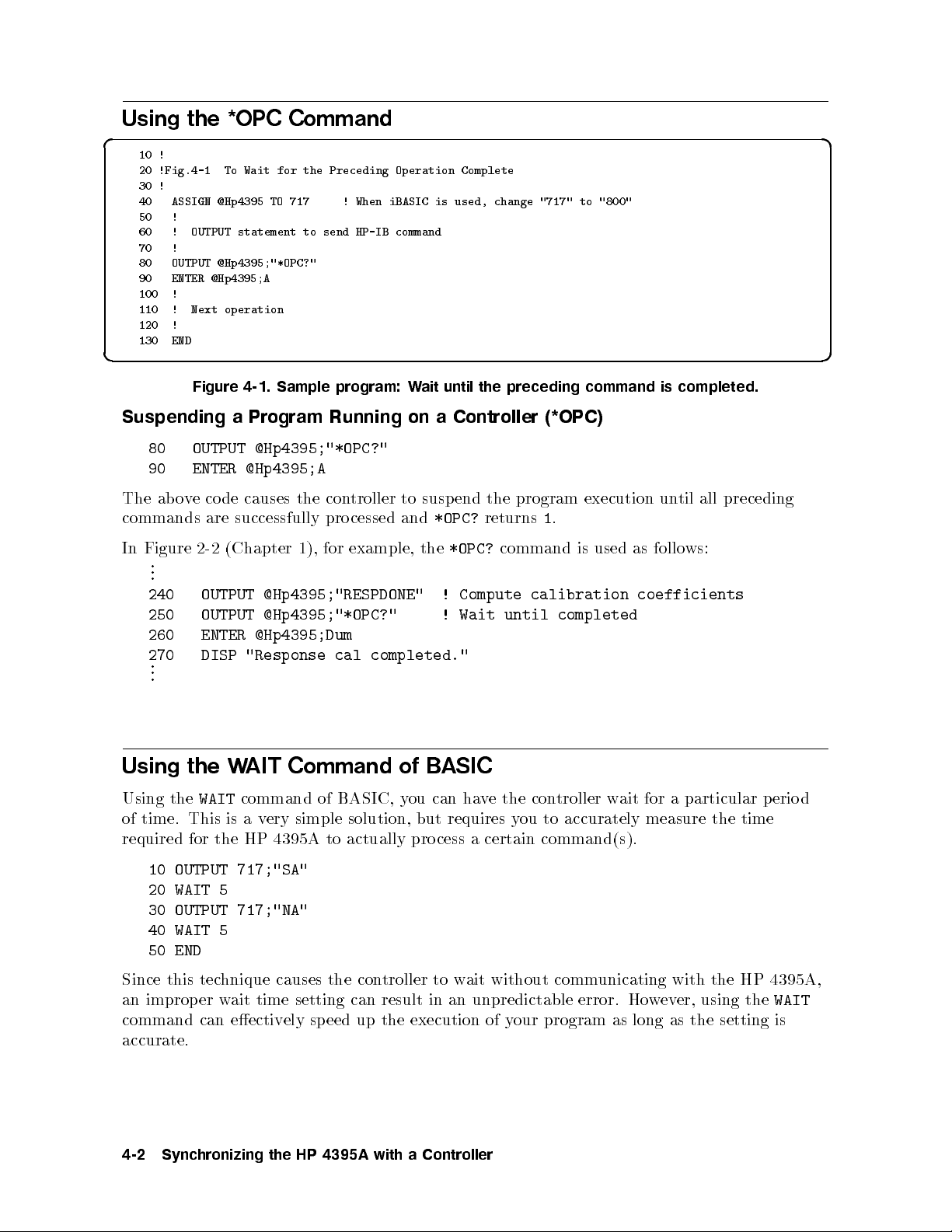
Using the *OPC Command
d a
10 !
20 !Fig.4-1 To Wait for the Preceding Operation Complete
30 !
40 ASSIGN @Hp4395 TO 717 ! When iBASIC is used, change "717" to "800"
50 !
60 ! OUTPUT statement to send HP-IB command
70 !
80 OUTPUT @Hp4395;"*OPC?"
90 ENTER @Hp4395;A
100 !
110 ! Next operation
120 !
130 END
c b
Figure 4-1. Sample program: Wait until the preceding command is completed.
Suspending a Program Running on a Controller (*OPC)
80 OUTPUT @Hp4395;"*OPC?"
90 ENTER @Hp4395;A
The above code causes the controller to suspend the program execution until all preceding
commands are successfully processed and
*OPC?
returns1.
In Figure 2-2 (Chapter 1), for example, the
.
.
.
*OPC?
command is used as follows:
240 OUTPUT @Hp4395;"RESPDONE" ! Compute calibration coefficients
250 OUTPUT @Hp4395;"*OPC?" ! Wait until completed
260 ENTER @Hp4395;Dum
270 DISP "Response cal completed."
.
.
.
Using the WAIT Command of BASIC
Using the
WAIT
command of BASIC, you can have the controller wait for a particular period
of time. This is a very simple solution, but requires you to accurately measure the time
required for the HP 4395A to actually process a certain command(s).
10 OUTPUT 717;"SA"
20 WAIT 5
30 OUTPUT 717;"NA"
40 WAIT 5
50 END
Since this technique causes the controller to wait without communicating with the HP 4395A,
an improper wait time setting can result in an unpredictable error. However, using the
WAIT
command can eectively speed up the execution of your program as long as the setting is
accurate.
4-2 Synchronizing the HP 4395A with a Controller
Page 63

Using the EXECUTE Statement to Synchronize with the Completion
of Sweep
d a
10 !
20 !Fig.4-2 To Wait for the Preceding Operation Complete
30 !
40 ASSIGN @Hp4395 TO 800 ! Only iBASIC is available
50 !
60 ! OUTPUT statement to send HP-IB command
70 !
80 EXECUTE "SING"
90 OUTPUT @Hp4395;"MKR ON"
100 OUTPUT @Hp4395;"SEAM MAX"
110 ! Next operation
120 !
130 END
c b
Figure 4-2. Sample program: Wait until the preceding command is completed.
Here is a tip: You can just issue a single EXECUTE \SING" statement to synchronize with
the completion of sweep. This is useful, for example, when you want to use the marker after a
single cycle of measurement.
80 EXECUTE "SING"
This causes the controller to wait until one cycle of sweep is completed.
90 OUTPUT @Hp4395;"MKR ON"
100 OUTPUT @Hp4395;"SEAM MAX"
Because the measurement is already completed, you can eectively use the marker.
Note that the
EXECUTE
command is supp orted for Instrument BASIC only.
Using SRQ
You can also use an SRQ to implement synchronization with the completion of sweep. This
technique is recommended when you are using an external controller. For how to synchronize
an SRQ with the completion of a sweep pro cess that uses an SRQ, refer to \ToWait for
Sweep End" in Chapter 5.
Synchronizing the HP 4395A with a Controller 4-3
Page 64

Using the *WAI Command
Note
If the active controller is an external controller, using the
*WAI
command
cannot perfectly synchronize the controller with the HP 4395A.
The
*WAI
command prevents the HP 4395A from pro cessing any newly received commands
until it nishes processing all preceding commands. If the HP 4395A receives a new HP-IB
command during the wait, it stores the command in a buer.
Example)
10 OUTPUT 717;"SING"
20 OUTPUT 717;"*WAI"
30 OUTPUT 717;"AUTO"
40 PRINT "Program end"
50 END
AUTO
The above program inhibits the HP 4395A from processing the
completion of the
whether or not the
HP 4395A do es not execute the
regardless of the program execution on the con
SING
command. However, the controller executes line 40 of the program,
SING
command has b een successfully processed. On the other hand, the
AUTO
command until the completion of the
troller.
command until the
SING
command,
4-4 Synchronizing the HP 4395A with a Controller
Page 65
Status Reporting System and Processing Generated
Interruptions
The analyzer has a status reporting ssytem to report the condition of the analyzer. This
chapter gives you an overview of the status reporting system.
This chapter provides the following information:
General status register model
Status bit denitions of the Status Byte
Status bit denitions of the Standard Event Status Register
Status bit Denitions of the Operation Status Register
OSPT, OSNT
Using the Service Request (SRQ)
Reporting command error occurrence (with sample program)
Waiting for sweep end (with sample program)
5
What is an SRQ?
An SRQ (Service Request) is an interrupt generated by the
analyzer. The analyzer can be setup to sen
the attention of the controller. The controller can ignore the SRQ
or it can b e setup to interrupt the program using the ON INTR
commands. The Status Byte can be used to dene the specic
event that generates an SRQ (for example, the end of sweep
complete).
tan SRQ when it needs
Status Reporting System and Processing Generated Interruptions 5-1
Page 66

General Status Register Model
The analyzer has a status reporting system to report the condition of the analyzer.
Figure 5-1. General Status Register Model
The status rep orting system has a hierarchical structure as shown in Figure 5-1. When the
analyzer condition satises the particular condition, the corresponding bit of the ev
is set \1". Therefore, you can check the analyzer condition by reading the event register.
ent register
When the event register bit is set to \1", and corresp onding enable register bit is also \1", the
summary bit of the status byte register is set to \1". You can read the status byte register by
using the serial poll.
If the corresp onding bit of the service request enable register is \1", the service request (SR
is generated with the positive transition of the status b
SRQ, you can notify the controller that the analyzer is requesting service.
Event Register
Reects the correspondent analyzer condition as a bit status. These bits monitor the changing
analyzer state continuously and change the bit status as required.
You cannot change bit status by HP-IB command.
The analyzer has the following event registers:
Standard Event Status Register (ESB) Contains the summary of general processing which
includes completion of sweep. See Table 5-2 for details.
Event Status Register (ESR) Contains the information on occurrence of an op eration failure
such as a command error. See Table 5-3 for details.
Operation Status Event Register (OSR) Contains only the information that a program is
runnig and/or data is b eing transfered to the prin
yte register bit. By generating the
ter. See Table 5-4 for details.
Q)
5-2 Status Reporting System and Processing Generated Interruptions
Page 67

Enable Register
The enable register selects whichevent register bits can set the bit in the summary bit of the
status byte register that is connected to SRQ generation. The register bits work like mask
bits. When you want to set a bit in the status byte register by a specic register condition,
set the corresp onding enable register to 1. This sets a 1 bit in the status byte register with a
corresponding event register bit.
Status Byte Register
If enabled event register is set to 1, the corresponding bit of the status byte register is set to
1. This register also indicates the output queue and SRQ status.
The value of the status byte register can be read by using the
SPOLL
statement or the
*STB?
query from the controller. Reading the status byte register by either command does not aect
the contents of the status byte register. Table 5-1 lists the contents of the status byte register.
A serial poll initiated by using the
the RQS bit. The
*STB?
command reads bit 6 as the MSS bit.
SRQ (Service Request) can be generated b
SPOLL
command reads bit 6 of the status byte register as
y the status byte register by setting the service
request enable register. For more information about SRQ, see Figure 5-6 in this chapter.
Transition Filter and Condition Register
The transition lter allows you to select which transitions of the analyzer condition will set a
bit in the event register.
When the status register has a transition lter, there is a lo
wer register called a condition
register under the event register. The transition lter is between the event register and the
condition register. The transition lter enables you to select a positive and/or negative
transition of the condition register bit to set a bit in the corresp onding ev
example, if you set the negative transition lter, a 1 is set in the ev
ent register bychanging
ent register. For
from 1 to 0 in the event register.
Figure 5-2. Transition Filter and Condition Register
Status Reporting System and Processing Generated Interruptions 5-3
Page 68

For the HP 4395A, only the \Program Running" bit of the operation status register has a
transition lter. By using the transition lter, you can generate an SRQ either at the start or
the end of the program execution.
5-4 Status Reporting System and Processing Generated Interruptions
Page 69

Status Register Structure
Figure 5-3 shows the status rep orting structure of the HP 4395A.
Figure 5-3. Status Reporting Structure
Status Reporting System and Processing Generated Interruptions 5-5
Page 70

Status Bit Definitions of the Status Byte (STB)
The status bytes consist of 8-bit registers, with each bit representing a specic analyzer
condition. The value of the Status Byte can b e read by using
SPOLL(717)
statement from an
external controller. This command reads a value directly from the analyzer without being
set to remote. So, you can operate front panel keys while a controller is reading the Status
Byte. Contents of the Status Byte can also be read by using the
*STB?
command. Reading
the Status Byte does not aect the contents of the Status Byte. Table 5-1 shows contents of
Status Byte.
Table 5-1. Status Bit Definitions of the Status Byte (STB)
Bit Name Description
2 Event Status Register B
Summary Bit
3 Questionable Status
Register Summary Bit
One of the enabled bits in Event Status Register B (Instrument
Event Status Register) has b een set.
The analyzer has no op eration to report the event to the
Questionable Status Register group. This register is available to
keep the consistency with other SCPI compatible instruments.
4 Message in Output
Queue
5 Standard Event Status
Register Summary Bit
6 Request Service One of the enabled Status Byte bits is causing an SR
7 Operation Status
Register Summary Bit
A command has prepared information to b e output, but it has
not been read yet.
One of the enabled bits in the Standard Ev
ent Status Register
has b een set.
Q.
One of the enabled bits in the Operation Status Register has been
set.
For example, to read the contents of Message in the output queue,
d a
10 Stat=SPOLL(717)
20 Stb4=BIT(Stat,4)
30 PRINT Stb4
40 END
c b
Figure 5-4. Example of Reading Status Byte (1)
or,
d a
10 ASSIGN Hp4395 TO 717
20 OUTPUT Hp4395;"*STB?"
30 ENTER Hp4395;Stat
40 Stb4=BIT(Stat,4)
50 PRINT Stb4
60 END
c b
Figure 5-5. Example of Reading Status Byte (2)
5-6 Status Reporting System and Processing Generated Interruptions
Page 71

Status Bit Definitions of ESB, ESR, and OSR
The Standard Event Status Register (
Status Register), and Operation Status Register (
ESR
), Event Status Register B (
OSR
) are subordinate to the Status Byte.
ESB
; InstrumentEvent
Each register can set a bit with a condition that is watched by status bit. A status bit is
cleared when it is read by query or the
CLESor*CLS
command is executed.
Table 5-2. Status Bit Definitions of the Standard Event Status Register (ESR)
Bit Name Description
0 Operation Complete A command for which OPC has b een enabled, and completed an
operation.
1 Request Control The analyzer has been commanded to perform an op eration that
requires control of a peripheral, and needs control of HP-IB.
2 Query Error 1. The analyzer has been addressed to talk, but there is nothing
in the output queue to transmit.
2. Data in the Output Queue has been lost.
3 Device Dep endent Error An error, other than a command error, a query error, and an
execution error has o ccurred.
4 Execution Error 1. A program data element following a header exceeded its input
range, or is inconsistent with the analyzer's capabilities.
2. A valid program message could not be prop erly executed due
to some analyzer condition.
5 Command Error 1. An IEEE 488.2 syntax error has o ccurred. Possible violations
include, a data element violated the analyzer listening formats
or a data elementtyp e is unacceptable to the analyzer.
2. A semantic error that indicates an unrecognized header w
as
received has occurred. Unrecognized headers include incorrect
device-specic headers and incorrect or unimplemented IEEE
488.2 common commands.
3. A Group Execute Trigger (
GET
)was entered into the Input
Buer of a program message.
6 User Request The operator pressed a front panel key or an optional keyboard
key or turned the rotary knob.
7 Power ON This bit is set when a p ower-on sequence occurs.
Status Reporting System and Processing Generated Interruptions 5-7
Page 72
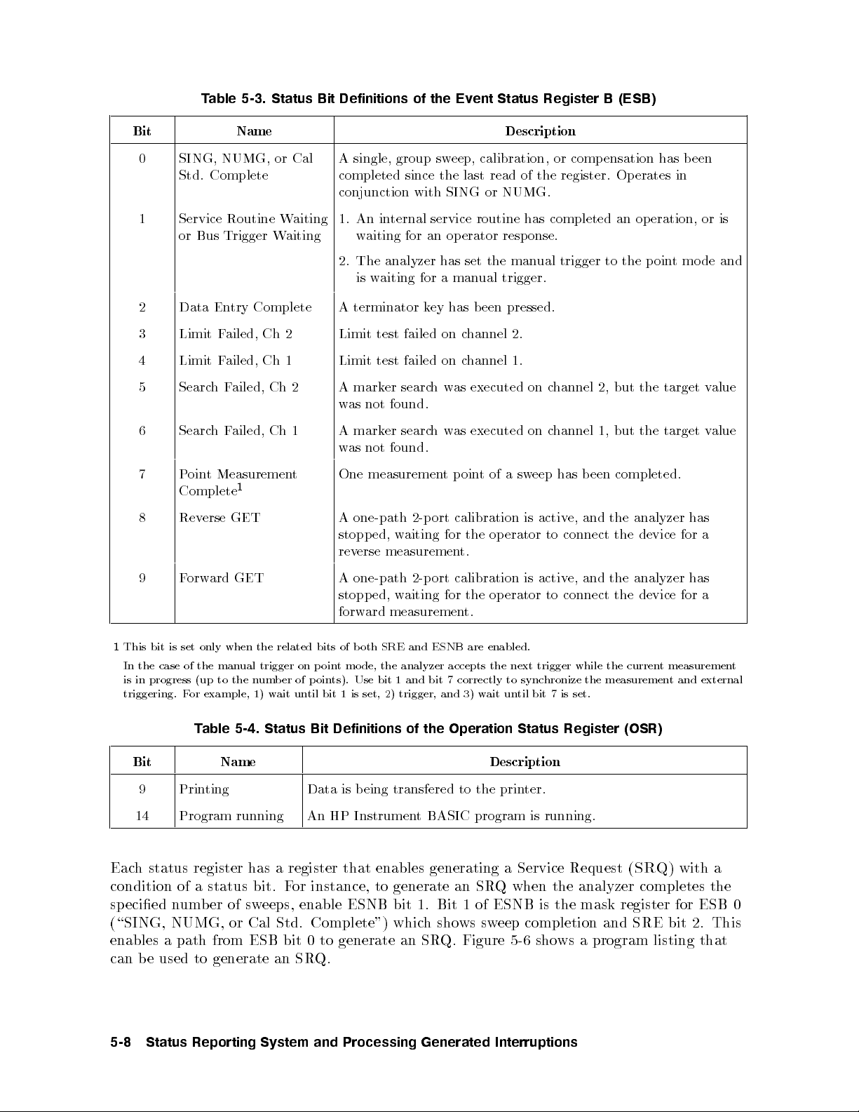
Table 5-3. Status Bit Definitions of the Event Status Register B (ESB)
Bit Name Description
0 SING, NUMG, or Cal
Std. Complete
A single, group sweep, calibration, or compensation has been
completed since the last read of the register. Operates in
conjunction with SING or NUMG.
1 Service Routine Waiting
or Bus Trigger Waiting
1. An internal service routine has completed an operation, or is
waiting for an op erator response.
2. The analyzer has set the manual trigger to the point mode and
is waiting for a manual trigger.
2 Data Entry Complete A terminator key has been pressed.
3 Limit Failed, Ch 2 Limit test failed on channel 2.
4 Limit Failed, Ch 1 Limit test failed on channel 1.
5 SearchFailed, Ch 2 A marker searchwas executed on channel 2, but the target value
was not found.
6 SearchFailed, Ch 1 A marker searchwas executed on channel 1, but the target value
was not found.
7 Point Measurement
Complete
1
One measurement pointofasweep has been completed.
8 Reverse GET A one-path 2-p ort calibration is active, and the analyzer has
stopped, waiting for the op erator to connect the device for a
reverse measurement.
9 Forward GET A one-path 2-p ort calibration is active, and the analyzer has
stopped, waiting for the op erator to connect the device for a
forward measurement.
1
This bit is set only when the related bits of both SRE and ESNB are enabled.
In the case of the manual trigger on point mo de, the analyzer accepts the next trigger while the current measuremen
is in progress (up to the number of points). Use bit 1 and bit 7 correctly to synchronize the measuremen
t and external
triggering. For example, 1) wait until bit 1 is set, 2) trigger, and 3) wait until bit 7 is set.
Table 5-4. Status Bit Definitions of the Operation Status Register (OSR)
Bit Name Description
9 Printing Data is being transfered to the printer.
14 Program running An HP Instrument BASIC program is running.
Each status register has a register that enables generating a Service Request (
SRQ
) with a
condition of a status bit. For instance, to generate an SRQ when the analyzer completes the
specied number of sweeps, enable ESNB bit 1. Bit 1 of ESNB is the mask register for ESB 0
(\SING, NUMG, or Cal Std. Complete") which shows sweep completion and SRE bit 2. This
enables a path from ESB bit 0 to generate an SR
can be used to generate an SR
Q.
Q. Figure 5-6 shows a program listing that
t
5-8 Status Reporting System and Processing Generated Interruptions
Page 73

d a
10 ASSIGN Hp4395 TO 717
20 !
30 OUTPUT Hp4395;"CLES" ! Clears status registers
40 OUTPUT Hp4395;"ESNB 1" ! Enables mask register of "SING. NUMG. or
50 ! ! Cal Std. Complete" of ESB
60 OUTPUT Hp4395;"*SRE 4" ! Enables mask register of "Event Status
70 ! ! Register B" of STB
80 !
90 ON INTR 7 GOTO End ! Declare SRQ interrupt
100 ENABLE INTR 7;2
110 OUTPUT Hp4395;"SING" ! Execute single sweep
120 GOTO 120 ! Endless loop
130 !
140 End: ! Exit from loop when sweep is completed
150 END
c b
Figure 5-6. Example of Generating a Service Request (SRQ)
OSPT, OSNT
OSPT (Operation Status Positive Transition Filter)
Sets the positiv e transition lter. Setting a bit in OSPT will cause a 0 to 1 transition in the
osr
corresponding bit of the associated Operation Status Register (
in the asso ciated bit of corresp onding Op eration Status Ev
ent Register (
) to cause a 1 to be written
oser
).
Bit 14 of the analyzer's OSR is used to sho
w program status. When bit 14 of OSPT is set to
1, starting a program causes a 1 to be written in bit 14 of OSER. (This sets bit 7 of STB to
1.)
OSNT (Operation Status Negative Transition Filter)
Sets the negative transition lter. Setting a bit in the negativ
e transition lter will cause a 1
to 0 transition in the corresponding bit of the asso ciated Op eration Status Register to cause a
1 to be written in the associated bit of corresponding Operation Status Event Register.
Bit 14 of the analyzer's OSR is used to show program status. When bit 14 of OSNT is set to
1, stopping a program causes a 1 to be written in bit 14 of OSER. (This sets bit 7 of STB to
1.)
Status Reporting System and Processing Generated Interruptions 5-9
Page 74

How to Use the Status Registers in a Program
You can use the status registers to determine the specic analyzer status in the program. To
determine the contents of the status register, the following metho ds are used:
Read an event register directly.
Use the Service Request (SRQ).
Reading an Event Register Directly
You can read the contents of the event register directly to determine the specic analyzer
condition. Use this method if you do not need to know the timing of the event register
changes. The following procedure reads the register directly:
1. Query the event register or the condition register contents.
2. Retrieve a return value.
The list shown below is an HP-BASIC sample program using the BIT function.
OUTPUT @Hp4395"ESB?"
ENTER @Hp4395Esb
IF BIT(Esb,4) THEN
DISP "LIMIT TEST FAILED AT Ch 1."
Queries instrument event status register contents.
Retrieve return value.
If bit 4 of the instrument event status r
egister is set to 1, the limit test
failed on channel 1.
END IF
Module 4-. Reading an Event Register
Related HP-IB Commands. The following query commands can be used to read the
contents of an event register directly.
*STB?
*ESR?
ESB?
OSR?
Returns Status Byte Register contents.
Returns Event Status Register contents.
Returns InstrumentEvent Status Register contents.
Returns Operation Status Register contents.
5-10 Status Reporting System and Processing Generated Interruptions
Page 75
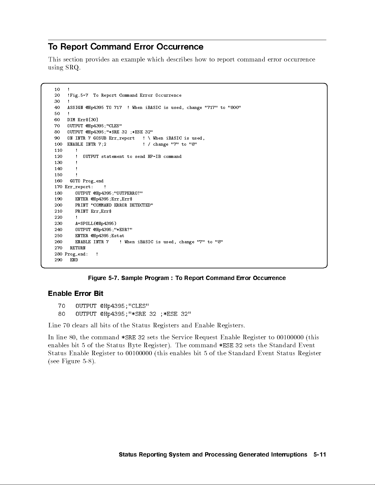
To Report Command Error Occurrence
This section provides an example which describes how to report command error occurrence
using SRQ.
d a
10 !
20 !Fig.5-7 To Report Command Error Occurrence
30 !
40 ASSIGN @Hp4395 TO 717 ! When iBASIC is used, change "717" to "800"
50 !
60 DIM Err$[30]
70 OUTPUT @Hp4395;"CLES"
80 OUTPUT @Hp4395;"*SRE 32 ;*ESE 32"
90 ON INTR 7 GOSUB Err_report ! \ When iBASIC is used,
100 ENABLE INTR 7;2 ! / change "7" to "8"
110 !
120 ! OUTPUT statement to send HP-IB command
130 !
140 !
150 !
160 GOTO Prog_end
170 Err_report: !
180 OUTPUT @Hp4395;"OUTPERRO?"
190 ENTER @Hp4395;Err,Err$
200 PRINT "COMMAND ERROR DETECTED"
210 PRINT Err,Err$
220 !
230 A=SPOLL(@Hp4395)
240 OUTPUT @Hp4395;"*ESR?"
250 ENTER @Hp4395;Estat
260 ENABLE INTR 7 ! When iBASIC is used, change "7" to "8"
270 RETURN
280 Prog_end: !
290 END
c b
Figure 5-7. Sample Program : To Report Command Error Occurrence
Enable Error Bit
70 OUTPUT @Hp4395;"CLES"
80 OUTPUT @Hp4395;"*SRE 32 ;*ESE 32"
Line 70 clears all bits of the Status Registers and Enable Registers.
In line 80, the command
enables bit 5 of the Status Byte Register). The command
*SRE 32
sets the Service Request Enable Register to 00100000 (this
*ESE 32
sets the Standard Event
Status Enable Register to 00100000 (this enables bit 5 of the Standard Event Status Register
(see Figure 5-8).
Status Reporting System and Processing Generated Interruptions 5-11
Page 76

Figure 5-8. Command-Error Bit Enabling
Report Command Error
90 ON INTR 7 GOSUB Err_report ! \ When iBASIC is used,
100 ENABLE INTR 7;2 ! / change "7" to "8"
110 !
120 ! OUTPUT statement to send HP-IB command
130 !
140 !
150 !
160 GOTO Prog_end
170 Err_report: !
If an HP-IB command (executed between lines 100 and 160) causes an HP-IB command error,
the analyzer generates an SRQ and the controller branches to
OUTPUT
statement:
Err_report
.For example, the
120 OUTPUT @Hp4395;"CENT "
Output Error
180 OUTPUT @Hp4395;"OUTPERRO?"
190 ENTER @Hp4395;Err,Err$
200 PRINT "COMMAND ERROR DETECTED"
210 PRINT Err,Err$
These commands retrieve the error number and description.
In the error shown in the line 120 example, the con
5-12 Status Reporting System and Processing Generated Interruptions
Setting center frequency, but no parameter
troller displays the following:
Page 77

d a
COMMAND ERROR DETECTED
-109 "Missing parameter"
Many dierent kinds are dened for HP-IB errors. Refer to the error code table when an error
occurs.
Return to Execute HP-IB command
230 A=SPOLL(@Hp4395)
240 OUTPUT @Hp4395;"*ESR?"
250 ENTER @Hp4395;Estat
260 ENABLE INTR 7 ! When iBASIC is used, change "7" to "8"
270 RETURN
Lines 230 to 270 clear SRQ before returning to the main routine.
Line 230 reads the analyzer's status byte. The
Byte Register of the address
@Hp4395
(analyzer), and enters the value intoA. The command
A=SPOLL(@Hp4395)
statement reads the Status
error causes the SRQ and with bit 5 and bit 6 of the Status Byte Register set, the v
is 96. Reading the Status Byte Register by using the
SPOLL
command clears SRQ (status byte
bit 6).
In line 240 and line 250, the command
Register. With Bit 5 of Standard Event Status Register set, the value of
the Standard Event Status Register by using the
A branchto
Err_report
disables the interrupt. Therefore, the return from
*ESR?
reads the contents of the Standard Event Status
*ESR?
Estat
command clears the register.
is 32. Reading
Err_report
reenable the interrupt.
alue of
must
A
Status Reporting System and Processing Generated Interruptions 5-13
Page 78

ToWait for Sweep End
d a
10 !
20 !Fig.5-9 To Wait for Sweep End
30 !
40 ASSIGN @Hp4395 TO 717 ! When iBASIC is used, change "717" to "800"
50 OUTPUT @Hp4395;"TRGS INT"
60 OUTPUT @Hp4395;"CLES"
70 OUTPUT @Hp4395;"*SRE 4;ESNB 1"
80 ON INTR 7 GOTO Sweep_end ! \ When iBASIC is used, change "7" to "8"
90 ENABLE INTR 7;2 !/
100 OUTPUT @Hp4395;"SING"
110 Measuring:GOTO Measuring
120 Sweep_end: !
130 DISP "MEASUREMENT COMPLETE"
140 END
c b
Figure 5-9. Sample Program : ToWait for Sweep End
Enable Sweep-End Bit
60 OUTPUT @Hp4395;"CLES"
70 OUTPUT @Hp4395;"*SRE 4;ESNB 1"
Line 60 clears all bits of the Status Registers and the Enable Registers.
In line 70, the command
enables bit 2 of the Status Byte Register). The command
*SRE 4
sets the Service Request Enable Register to 00000100 (this
ESNB 1
Register B to 0000000000000001 (this enables bit 0 of the Ev
Figure 5-10).
sets the Event Status Enable
ent Status Register B. See
Figure 5-10. Sweep-End Bit Enabling
Enable Registers select whichevents in the analyzer can cause a service request (SR
Q). By
setting bit 0 of the Event Status Enable Register B to 1, the occurrence of the corresponding
5-14 Status Reporting System and Processing Generated Interruptions
Page 79

event (sweep-end) sets bit 0 of the Event Status Register B. When this bit is set (and is
enabled), itis used to set a summary bit in the Status Byte Register (bit 2). Also, because
bit 2 of Service Request Enable Register is set, setting the corresponding bit (Event Status
Register B summary bit) generates an SRQ. The SRQ sets bit 6 of the Status Byte Register.
Enable SRQ Interrupt
80 ON INTR 7 GOTO Sweep_end ! \ When iBASIC is used, change "7" to "8"
90 ENABLE INTR 7;2 !/
.
.
.
120 Sweep_end: !
Line 80 denes a branch. When the SRQinterrupt is generated from the HP-IB interface
(whose select co de is 7), the controller go es to
Sweep_end
(Line 120).
Line 90 enables an interrupt from interface 7 (HP-IB) when bit 1 (SRQ bit) of the interrupt
register (of the controller) is set byavalue of 2.
Wait Until Measurement Is Done
100 OUTPUT @Hp4395;"SING"
110 Measuring: GOTO Measuring
The controller loops back in line 110 until an SRQinterrupt o ccurs.
Generate SRQ
On a single sweep end, bit 0 of the ESB is set (whic
h sets bit 2 of the Status Byte Register)
and an SRQ is generated.
120 Measuring: GOTO Measuring
130 Sweep_end: !
Loop until SRQ interrupt
AtSRQ interrupt, jump to here
Once an SRQ is generated, the SRQinterrupt is disabled.
Status Reporting System and Processing Generated Interruptions 5-15
Page 80

Page 81

6
Using the Trigger System in HP 4395A
This chapter describes how to control the trigger system of the analyzer.
To trigger a measurement from a controller, the following steps are commonly used:
1. Set the trigger source to:
Bus, or Internal (free run)
(In External, Video, Manual or Gate trigger, you cannot trigger from the controller, so
these sources are not mentioned in this guide.)
2. Set the number of measurements and the analyzer is initiated. You can set the number of
measurements as:
(Hold)|Single|Number of Group|Continuous
3. Generate the trigger event and the analyzer starts a measurement.
The analyzer trigger system has three states: Idle, W
aiting for Trigger, and Measurement.
Figure 6-1. Trigger System
Using the Trigger System in HP 4395A 6-1
Page 82

In Figure 6-1,
1. After a
HOLD
HP-IB command execution, the analyzer returns to the \Idle" state.
2. By setting the number of measurements, the analyzer changes from the \Idle" state to the
\Waiting for Trigger" state.
3. At the \Waiting for Trigger" state, a trigger input (corresponding to the trigger source)
starts a measurement.
Bus HP-IB command
*TRG
or BASIC command
TRIGGER
triggers
measurements.
Internal (free run) There is no need for a trigger input. The analyzer starts the
measurements immediately.
4. After the measurement is complete, the next state depends on the number of
measurements.
Single goes to the \Idle" state(4-a).
Number of Groups Go es to the \Waiting for Trigger" state until the number of groups not
measured yet equals zero(4-b).
After all measurements are completed, goes to \Idle" state(4-a).
Continuous go es to the \Waiting for Trigger" state(4-b).
To Measure Continuously
d a
10 !
20 !Fig.6-2 To Trigger Measurement Continuously
30 !
40 ASSIGN @Hp4395 TO 717 ! When iBASIC is used, change "717" to "800"
50 OUTPUT @Hp4395;"TRGS INT"
60 OUTPUT @Hp4395;"CONT"
70 END
c b
Figure 6-2. Sample Program : To Trigger Measurements Continuously
Set Trigger Source
50 OUTPUT @Hp4395;"TRGS INT"
Set the trigger source to internal.
Start Continuous Measurement Sweep
60 OUTPUT @Hp4395;"CONT"
The analyzer changes to the \Waiting for Trigger" state. In this program, the internal trigger
source is selected and the analyzer immediately starts continuous measurements.
6-2 Using the Trigger System in HP 4395A
Page 83

What can you do to
abort a measurement?
Send the command:
OUTPUT @Hp4395;"HOLD"
Note
The HP 4395A will fail in prop er measurement data transfer when it is
triggerd using the internal trigger source. If you want to transfer measurement
data to the controller, you must use either the
SING
or the
NUMG
parameter
command to synchronize the controller and the analyzer. To use these
commands, see \Using the EXECUTE Statement to Synchronize with
the Completion of Sweep" in Chapter 4 and \ToWait for Sweep End" in
Chapter 5.
To Trigger a Measurement From the Controller
Two metho ds of triggering a measurement from the controller are shown in Figure 6-3 and
Figure 6-4.
d a
10 !
20 !Fig.6-3 To Trigger Measurement From Controller(1)
30 !
40 ASSIGN @Hp4395 TO 717 ! When iBASIC is used, change "717" to "800"
50 OUTPUT @Hp4395;"TRGS INT"
60 OUTPUT @Hp4395;"SING"
70 END
10 !
c b
Figure 6-3. Sample Program : To Trigger a Measurement from Controller (1)
Set Trigger Source
50 OUTPUT @Hp4395;"TRGS INT"
Set the trigger source to internal.
Trigger a Measurement
60 OUTPUT @Hp4395;"SING"
The analyzer changes to the \Waiting for Trigger" state. In this program, the internal source
is selected and the analyzer immediately starts a measurement. After the measurement, the
analyzer go es to the \Idle" state.
How can you perform
averaging?
When you set the averaging on, you must also set the number of
measurements to the same value as the averaging factor. For
example, if the averaging factor is 10, replace line 60 as follows:
60 OUTPUT @Hp4395;"NUMG 10"
How can you wait for a
measurementtobe
completed?
When you want to return the measurement data to the controller,
you must wait for the measurement to be completed. For details,
see Chapter 4.
Using the Trigger System in HP 4395A 6-3
Page 84

d a
10 !
20 !Fig.6-4 To Trigger Measurement From Controller(2)
30 !
40 ASSIGN @Hp4395 TO 717 ! When iBASIC is used, change "717" to "800"
50 OUTPUT @Hp4395;"TRGS BUS"
60 OUTPUT @Hp4395;"CONT"
70 OUTPUT @Hp4395;"*TRG"
80 END
c b
Figure 6-4. Sample Program : To Trigger a Measurement from Controller (2)
Set Trigger Source
50 OUTPUT @Hp4395;"TRGS BUS"
Set the trigger source to bus.
Trigger a Measurement
70 OUTPUT @Hp4395;"*TRG"
Triggers the analyzer. When the trigger source is set to bus, y
ou can use the group execution
trigger as follows:
70 TRIGGER 7
What is Group Execution
Trigger (GET)?
The HP BASIC command
*TRG
command. The HP BASIC command is used to trigger all
TRIGGER
can b e used instead of the
triggerable instruments on a BUS at the same time. Therefore, to
trigger all triggerable instruments on select code 7(HP-IB bus)
execute the command:
TRIGGER 7
Setting the Gate Trigger
The gate trigger can b e set via the controller, though it cannot b e controlled directly.You
should dene Gate Length and Gate Delay as b elow.
Gate Delay=/2 + SD
Gate Length =/4
Wheremeans Signal Length and SD means Signal. And you should measure these
parameters with an oscilloscope. See
Operation Manual
for details in the gate trigger.
6-4 Using the Trigger System in HP 4395A
Page 85

d a
10 !
20 !Fig.6-5 Gate Trigger configure
30 !
40 ASSIGN @Hp4395 TO 717 ! When iBASIC is used, change "717" to "800"
50 OUTPUT @Hp4395;"TRGS GAT"
60 OUTPUT @Hp4395;"GATCTL LEV"
70 OUTPUT @Hp4395;"GATDLY 10E-6"
80 OUTPUT @Hp4395;"GATLEN 100E-6"
90 END
c b
Figure 6-5. Sample Program : Setting the Gate Trigger
Setting the Gate Delay
70 OUTPUT @Hp4395;"GATDLY 10E-6"
Set the gate delayto10sec.
Setting the Gate Length
80 OUTPUT @Hp4395;"GATLEN 100E-6"
Set the gate length to 100sec.
Using the Trigger System in HP 4395A 6-5
Page 86

Page 87

7
Using the I/O Port
This chapter describes how to use the I/O port of the analyzer with the HP-IB. For general
operation of the I/O port, see the
The I/O p ort on the analyzer's rear panel communicates with external devices (for example, a
handler on a production line). HP 4395Ahas 8 bit I/O port and 24 bit I/O port.
Overview
This section gives you an overview of the usage of the I/O p ort, taking the 8-bit I/O port as
an example.
Operation Manual
.
Figure 7-1. 8-bit I/O Port
The I/O p ort consists of the following 15 TTL compatible signals:
8-bit output
4-bit input
3 grounds
The signals IN 0 to IN 3 and OUT 0 to OUT 7 can be read and set by HP-IB commands.
Using the I/O Port 7-1
Page 88

To Synchronize External Handler with Analyzer
d a
10 !
20 !Fig.7-2 Synchronization of an External Handler
30 ! with the Analyzer
40 !
50 ASSIGN @Hp4395 TO 717 ! When iBASIC is used, change "717" to "800"
60 !
70 !
80 OUTPUT @Hp4395;"OUT8IO 8"
90 !
100 REPEAT !
110 OUTPUT @Hp4395;"INP8IO?" !
120 ENTER @Hp4395;Inpio ! Waiting Handler Response
130 A=BIT(Inpio,3) !
140 UNTIL A=1 !
150 !
160 !
170 END
c b
Figure 7-2. Sample Program : Synchronization of an External Handler with the Analyzer
Send Signal to the External Handler
80 OUTPUT @Hp4395;"OUT8IO 8"
The
OUT8IO
8
command sets the OUT 3 line to TRUE (1).
parameter
command sets the 8-bit data value of the OUT 0-7 lines. The
OUT8IO
Figure 7-3. 8-Bit Data of OUT0-7
Figure 7-4. Sending Signal to an the External Handler
7-2 Using the I/O Port
Page 89

Read Signal from the External Handler
100 REPEAT
110 OUTPUT @Hp4395;"INP8IO?"
120 ENTER @Hp4395;Inpio
130 A=BIT(Inpio,3)
140 UNTIL A=1
The
INP8IO?
command returns the 4-bit data value of the IN 0-3 lines.
Lines 100 to 140 wait for the external handler to set signal on line IN 3 to TRUE (1).
Figure 7-5. Reading Signal from the External Handler
Using the I/O Port 7-3
Page 90
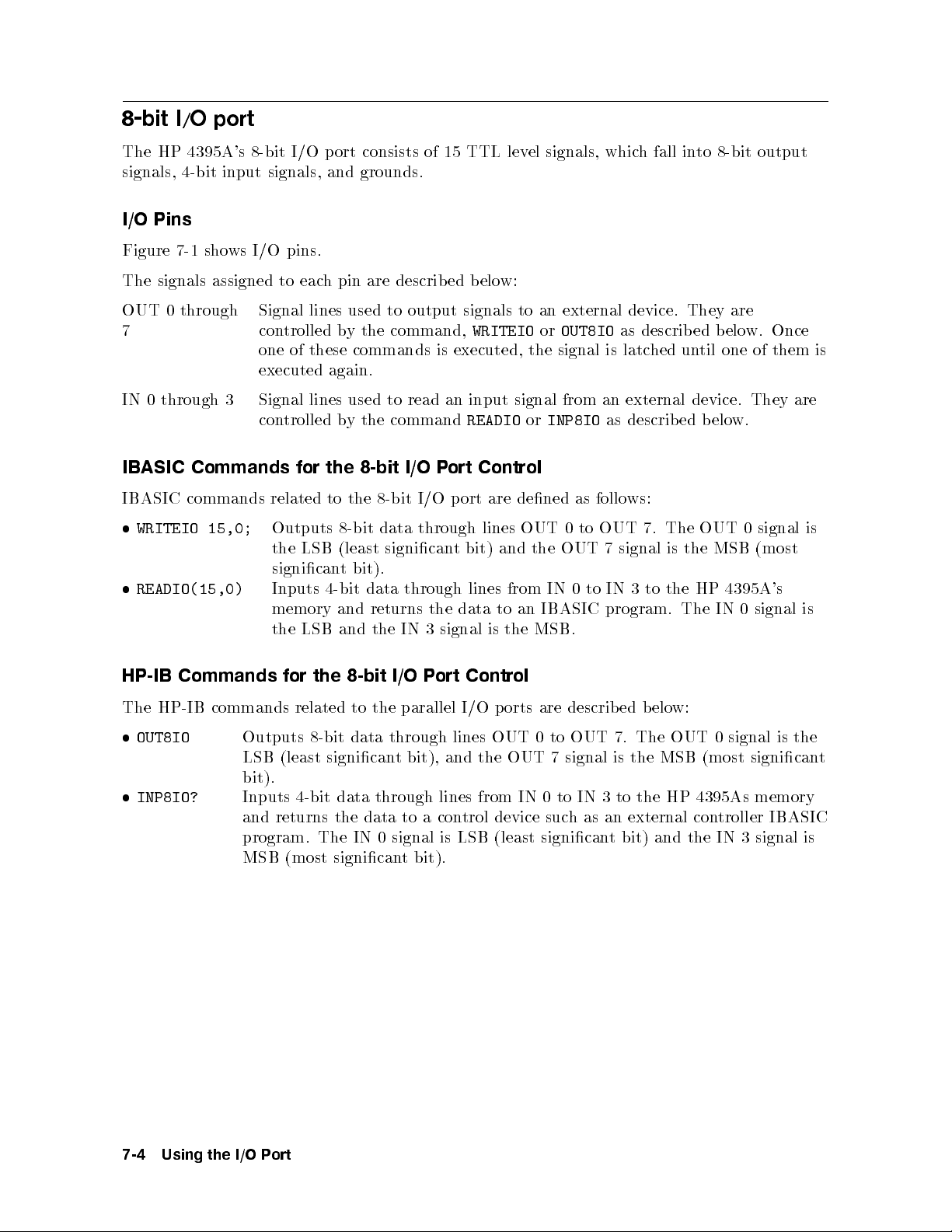
8-bit I/O port
The HP 4395A's 8-bit I/O port consists of 15 TTL level signals, which fall into 8-bit output
signals, 4-bit input signals, and grounds.
I/O Pins
Figure 7-1 shows I/O pins.
The signals assigned to each pin are described below:
OUT 0 through7Signal lines used to output signals to an external device. They are
controlled by the command,
WRITEIOorOUT8IO
as described below. Once
one of these commands is executed, the signal is latched until one of them is
executed again.
IN 0 through 3 Signal lines used to read an input signal from an external device. They are
controlled by the command
READIOorINP8IO
as described below.
IBASIC Commands for the 8-bit I/O Port Control
IBASIC commands related to the 8-bit I/O port are dened as follo ws:
WRITEIO 15,0;
Outputs 8-bit data through lines OUT 0 to OUT 7. The OUT 0 signal is
the LSB (least signicant bit) and the OUT 7 signal is the MSB (most
signicant bit).
READIO(15,0)
Inputs 4-bit data through lines from IN 0 to IN 3 to the HP 4395A's
memory and returns the data to an IBASIC program. The IN 0 signal is
the LSB and the IN 3 signal is the MSB.
HP-IB Commands for the 8-bit I/O Port Control
The HP-IB commands related to the parallel I/O ports are described belo
OUT8IO
Outputs 8-bit data through lines OUT 0 to OUT 7. The OUT 0 signal is the
LSB (least signicant bit), and the OUT 7 signal is the MSB (most signicant
bit).
INP8IO?
Inputs 4-bit data through lines from IN 0 to IN 3 to the HP 4395As memory
and returns the data to a control device such as an external controller IBASIC
program. The IN 0 signal is LSB (least signicant bit) and the IN 3 signal is
MSB (most signicant bit).
w:
7-4 Using the I/O Port
Page 91
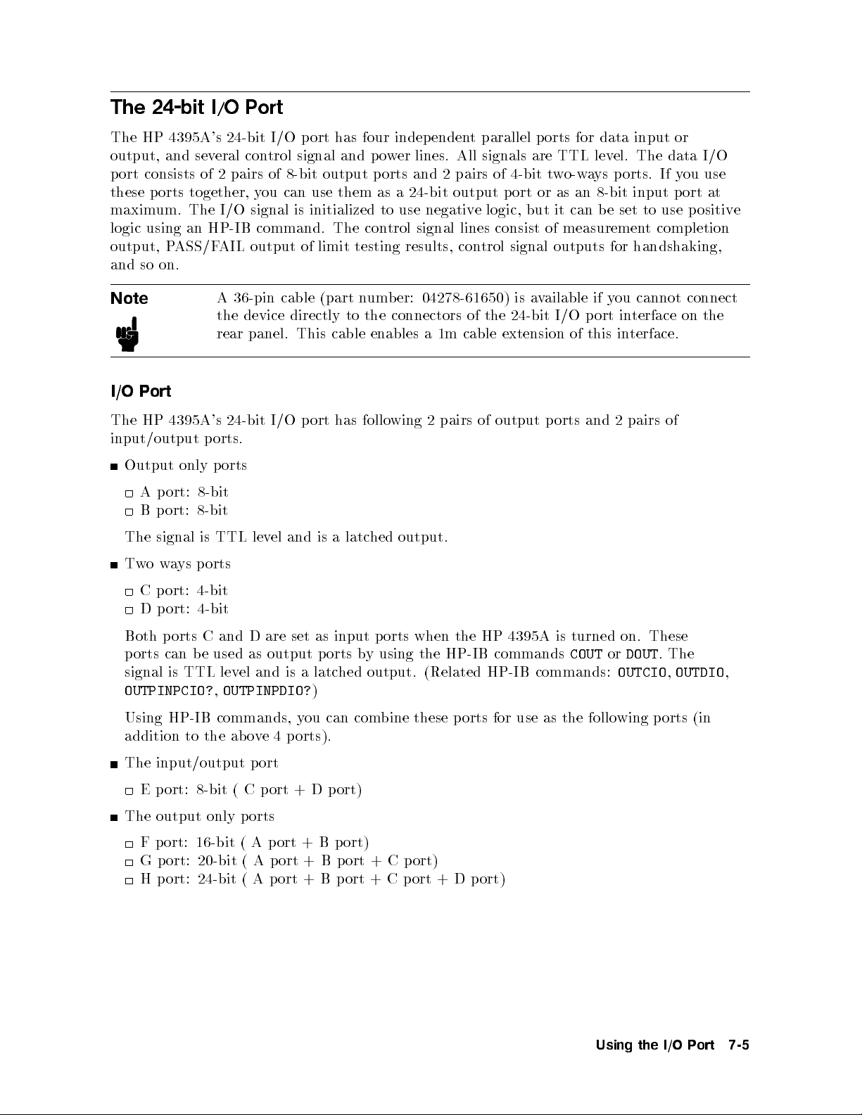
The 24-bit I/O Port
The HP 4395A's 24-bit I/O port has four independent parallel ports for data input or
output, and several control signal and p ower lines. All signals are TTL level. The data I/O
port consists of 2 pairs of 8-bit output ports and 2 pairs of 4-bit two-ways p orts. If you use
these ports together, you can use them as a 24-bit output port or as an 8-bit input port at
maximum. The I/O signal is initialized to use negative logic, but it can be set to use positive
logic using an HP-IB command. The control signal lines consist of measurement completion
output, PASS/FAIL output of limit testing results, control signal outputs for handshaking,
and so on.
Note
A 36-pin cable (part number: 04278-61650) is available if you cannot connect
the device directly to the connectors of the 24-bit I/O port interface on the
rear panel. This cable enables a 1m cable extension of this interface.
I/O Port
The HP 4395A's 24-bit I/O port has follo
wing 2 pairs of output ports and 2 pairs of
input/output ports.
Output only ports
A port: 8-bit
B port: 8-bit
The signal is TTL level and is a latched output.
Twoways ports
C port: 4-bit
D port: 4-bit
Both ports C and D are set as input p orts when the HP 4395A is turned on. These
ports can be used as output ports b
y using the HP-IB commands
signal is TTL level and is a latched output. (Related HP-IB commands:
OUTPINPCIO?,OUTPINPDIO?
)
COUTorDOUT
OUTCIO,OUTDIO
. The
,
Using HP-IB commands, you can combine these ports for use as the following ports (in
addition to the above 4 p orts).
The input/output port
E port: 8-bit ( C p ort + D p ort)
The output only p orts
F port: 16-bit ( A port + B port)
G port: 20-bit ( A port + B port + C port)
H port: 24-bit ( A port + B port + C port + D port)
Using the I/O Port 7-5
Page 92

Control Signal Lines
The I/O p orts include 10 types of output signal lines and one input signal line. These control
signals are TTL-compatible (excluding the power supply line). Each of them are describ ed
below.
Port C or Port D Status Output Signal
These signals are used to report the direction setting (input or output) of p ort C or D to
external devices. Each of these signals is set to LOW resp ectively when port C or D is
assigned as an input p ort. It is set to HIGH respectively when p ort C or D is dened as an
output port. (Related HP-IB commands:
CIN,COUNT,DIN
, and
DOUT
.)
WRITE STROBE Output Signal
When data is output to any output p ort, a negative pulse is output to the WRITE STROBE
output. This negative output pulse noties an external device of data output to the parallel
I/O port. The pulse width is 10s(typical). Figure 7-6 shows the timing chart for the
WRITE STROBE output and data output.
Figure 7-6. Write Strobe Signal Timing Chart
INPUT1 Input Signal
When a negative pulse is input to INPUT1, OUTPUT1 and OUTPUT2 are set to LOW
or HIGH. The time interval is 200 ns (typical). An HP-IB command is used to determine
whether LOW or HIGH is to be set. The pulse width of the signal input to INPUT1 must be
1s or more. (Related HP-IB commands:
TRGOUT
.)
OUT1ENVH,OUT1ENVL,OUT2ENVH,OUT2ENVL
, and
OUTPUT1 or OUTPUT2 Output Signal
This signal (a latch output signal) can be set to LOW or HIGH by inputting a negative pulse
to INPUT1 or using an HP-IB command. (Related HP-IB commands:
and
OUT2L
.)
Note
You can change the logic level of an OUTPUT signal by synchronizing
it with a measurement trigger, when you turn
output function using the HP-IB command
ON
TRGOUT ON
OUT1H,OUT1L,OUT2H
the trigger detection
. This function is used
only in frequency transient measurements to send a load signal to a device
immediately after a triggering measurement. The time interval between the
measurement trigger and the logic level change is 85s(typical).
7-6 Using the I/O Port
Page 93

PASS/FAIL Output
Outputs a HIGH (positive logic) or LOW (negative logic) signal when the limit test passed,
and a LOW (p ositive logic) or HIGH (negative logic) when the limit test failed. This is valid
when the limit test function is set to
WRITE STROBE Output for the PASS/FAIL Output
Outputs a negative pulse when a limit test result has been output through the PASS/FAIL
output line. The output signal informs an external device of the limit test result b eing output
through the PASS/FAIL output. The pulse width is 10s(typical).
SWEEP END Output
When the HP 4395A completes a measurement in the Tester mo de or a sweep in the Analyzer
mode, a negative pulse is output. When measurements are repeated with a continuous trigger,
the pulse is output at every measurementorsweep end. The pulse width is 20s(typical).
+5V Output
ON
.
A +5V output can b e provided to an external device. The maximum curren
mA. This line does not have a fuse. When excessive currentows, the HP 4395A's protection
circuit automatically shuts down its internal power supply circuits. If you remove the cause of
the excessive current, the HP 4395A's power will be turned on but the HP 4395A's setups are
reset to the default settings.
t supplied is 100
Using the I/O Port 7-7
Page 94
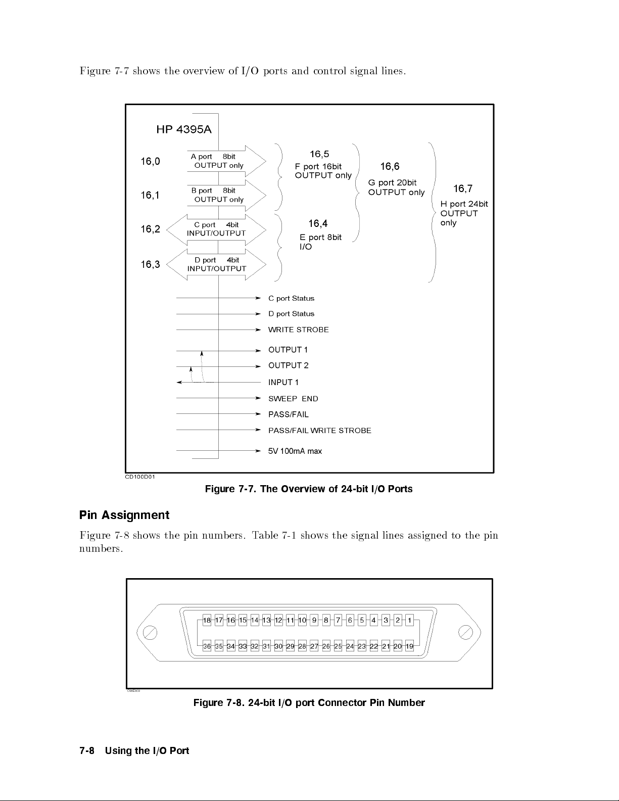
Figure 7-7 shows the overview of I/O ports and control signal lines.
Figure 7-7. The Overview of 24-bit I/O Ports
Pin Assignment
Figure 7-8 shows the pin numbers. Table 7-1 shows the signal lines assigned to the pin
numbers.
Figure 7-8. 24-bit I/O port Connector Pin Number
7-8 Using the I/O Port
Page 95
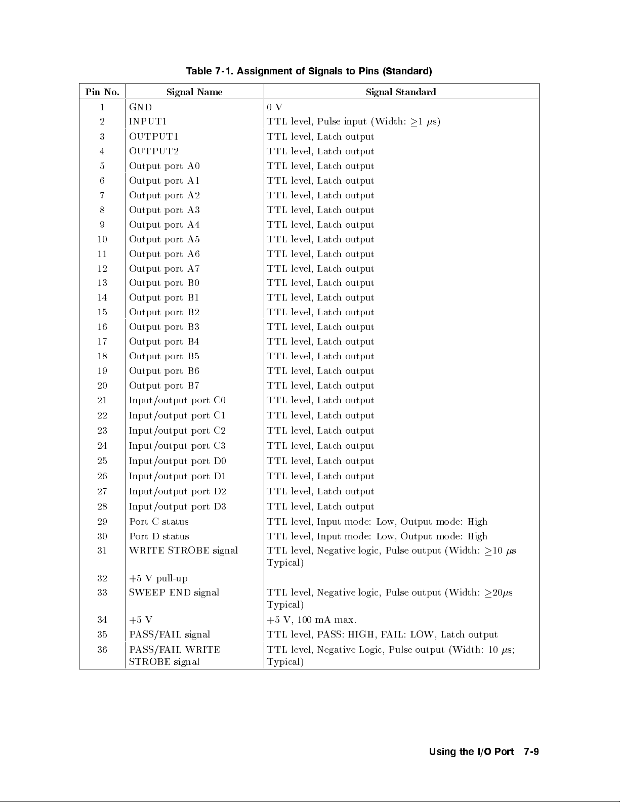
Table 7-1. Assignment of Signals to Pins (Standard)
Pin No. Signal Name Signal Standard
1 GND 0V
2 INPUT1 TTL level, Pulse input (Width:1s)
3 OUTPUT1 TTL level, Latch output
4 OUTPUT2 TTL level, Latch output
5 Output p ort A0 TTL level, Latch output
6 Output p ort A1 TTL level, Latch output
7 Output p ort A2 TTL level, Latch output
8 Output p ort A3 TTL level, Latch output
9 Output p ort A4 TTL level, Latch output
10 Output port A5 TTL level, Latch output
11 Output port A6 TTL level, Latch output
12 Output port A7 TTL level, Latch output
13 Output port B0 TTL level, Latch output
14 Output port B1 TTL level, Latch output
15 Output port B2 TTL level, Latch output
16 Output port B3 TTL level, Latch output
17 Output port B4 TTL level, Latch output
18 Output port B5 TTL level, Latch output
19 Output port B6 TTL level, Latch output
20 Output port B7 TTL level, Latch output
21 Input/output p ort C0 TTL level, Latch output
22 Input/output p ort C1 TTL level, Latch output
23 Input/output p ort C2 TTL level, Latch output
24 Input/output p ort C3 TTL level, Latch output
25 Input/output p ort D0 TTL level, Latch output
26 Input/output p ort D1 TTL level, Latch output
27 Input/output p ort D2 TTL level, Latch output
28 Input/output p ort D3 TTL level, Latch output
29 Port C status TTL level, Input mo de: Low, Output mode: High
30 Port D status TTL level, Input mo de: Low, Output mode: High
31 WRITE STROBE signal TTL level, Negative logic, Pulse output (Width:10s
Typical)
32 +5 V pull-up
33 SWEEP END signal TTL level, Negative logic, Pulse output (Width:20s
Typical)
34 +5 V +5 V, 100 mA max.
35 PASS/FAIL signal TTL level, PASS: HIGH, FAIL: LOW, Latch output
36 PASS/FAIL WRITE
STROBE signal
TTL level, Negative Logic, Pulse output (Width: 10s;
Typical)
Using the I/O Port 7-9
Page 96

Power-ON Default
The 24-bit I/O port is set to the following defaults at p ower-on. (These settings do not
change when
Logic type Negative logic
WRITE STROBE
signal
SWEEP END signal HIGH
Port A Negative 0
Port B Negative 0
Port C Input
Port D Input
OUTPUT1 HIGH, pulled HIGH by the falling edge of INPUT1 (
OUTPUT2 HIGH, pulled HIGH by the falling edge of INPUT1 (
PASS/FAIL signal (Negativ e)
4
Preset
5
is pressed.)
HIGH
0!
0!
0!
HIGH
HIGH
HIGH
OUT1ENVH
OUT2ENVH
)
)
7-10 Using the I/O Port
Page 97

Basic I/O circuit
Table 7-2. 24-bit I/O Port, Basic I/O Circuit
Basic
circuit
I/O pin
Basic
circuit
Input port
INPUT1 Port C, D (input)
Output port Others
1
I/O pins
OUTPUT1, 2
port A1,B1, C(output)1, D(output)
1
+5V pullup
Write strobe signal
SWEEP END signal
Port C status, Port D status
1
Common to all bits
IBASIC Commands for 24-bit I/O Port Control
IBASIC commands related to 24-bit I/O p ort are described in the following paragraphs.
Data Output
The following commands output data to the corresponding p orts (A to H). If you use C, D, E,
F, G, or H p ort as the output port, you must use the HP-IB command
COUT
and/or
DOUT
to
set the C and/or D port as an output port.
WRITEIO 16,0;
WRITEIO 16,1;
WRITEIO 16,2;
Output 8-bit data to p ort A.
Output 8-bit data to p ort B.
Output 4-bit data to p ort C.
Using the I/O Port 7-11
Page 98

WRITEIO 16,3;
WRITEIO 16,4;
WRITEIO 16,5;
WRITEIO 16,6;
WRITEIO 16,7;
Output 4-bit data to p ort D.
Output 8-bit data to p ort E.
Output 16-bit data to p ort F.
Output 20-bit data to p ort G.
Output 24-bit data to p ort H.
Data Input
The following commands read data sent from an external device to an input port (C to E) and
return the value to an HP IBASIC program. If you use the port as an input port, the p ort
must be dened as an input p ort using the HP-IB commands
READIO(16,2)
READIO(16,3)
READIO(16,4)
Reads 4-bit data from p ort C and returns the value.
Reads 4-bit data from p ort D and returns the value.
Reads 4-bit data from p ort E and returns the value.
CIN
and/or
DIN
.
HP-IB commands for 24-bit I/O port control
The HP-IB commands related to the parallel I/O ports are summarized b elow.
Data Output
The following commands output data to ports (A to H). If y
the output port, you must use the HP-IB command
COUT
ou use C, D, E, F, G or H p ort as
and/or
DOUT
to set the C, D port to
output port.
OUTAIO
OUTBIO
OUTCIO
OUTDIO
OUTEIO
OUTFIO
OUTGIO
OUTHIO
Outputs 8-bit data to p ort A.
Outputs 8-bit data to p ort B.
Outputs 4-bit data to p ort C.
Outputs 4-bit data to p ort D.
Outputs 8-bit data to p ort E.
Outputs 16-bit data to p ort F.
Outputs 20-bit data to p ort G.
Outputs 24-bit data to p ort H.
Data Input
The following commands read data sent from an external device to an input port (C to E) and
return the value to the HP-IB. If you use the port as an input port, the port must be dened
as an input port using the HP-IB command
OUTPINPCIO?
OUTPINPDIO?
OUTPINPEIO?
Reads 4-bit data from p ort C and returns its v
Reads 4-bit data from p ort D and returns its v
Reads 8-bit data from p ort E and returns its value to the HP-IB.
CIN
and/or
DIN
.
alue to the HP-IB.
alue to the HP-IB.
Setting Input/Output Directions of Ports C and D
The following commands set the input/output directions of p orts C and D. When the power is
turned ON, p orts C and D are dened as input ports.
4
Preset
5
does not aect the setup. This
setting is saved to an instrument state le using the Save function.
CIN
COUT
DIN
DOUT
Denes port C as an input port.
Denes port C as an output port.
Denes port D as an input port.
Denes port D as an output port.
7-12 Using the I/O Port
Page 99

Positive or Negative Logic Setting
You can set the logic level of the following ports and signal to negative or positive using the
following HP-IB command
4
5
does not aect this setup. This setup is saved to an instrument state le using the Save
Preset
NEGLorPOSL
. When the power is turned ON, negative logic is set.
function.
Output ports A to H
Input ports C and D
PASS/FAIL signal
OUTPUT1 and OUTPUT2 Level Setting Commands
The following commands set the logic level of OUTPUT1 and OUTPUT2.
OUT1H
OUT1L
OUT2H
OUT2L
Sets OUTPUT1 to HIGH.
Sets OUTPUT1 to LOW.
Sets OUTPUT2 to HIGH.
Sets OUTPUT2 to LOW.
Checking Input to INPUT1
This command checks whether a pulse has been input to INPUT1. Send this command after a
pulse has been input to INPUT1 and the return v
it will be \0". Once \1" is read by this command, it will b e reset to \
alue will b e \1". If no pulse has b een input,
0
"until the next pulse
is input.
Using the I/O Port 7-13
Page 100

 Loading...