

HP 4395A Network/Spectrum/Impedance Analyzer
Operation Manual
SERIAL NUMBERS
This manual applies directly to instruments which have the serial number prex JP1KE.
For additional important information about serial numbers,
read \Serial Number" in Appendix D of this Manual.
HP Part No. 04395-90010
Printed in JAPAN September 1998
Second Edition

Notice
The information contained in this document is subject to change without notice.
This document contains proprietary information that is protected by copyright. All rights are
reserved. No part of this document may be photocopied, reproduced, or translated to another
language without the prior written consent of the Hewlett-Packard Company.
Hewlett-Packard Japan, LTD.
Kobe Instrument Division
1-3-2, Murotani, Nishi-ku, Kobe-shi,
Hyogo, 651-2241 Japan
c
Copyright 1997,1998 Hewlett-Packard Japan, LTD.

Manual Printing History
The manual printing date and part number indicate its current edition. The printing date
changes when a new edition is printed. (Minor corrections and updates that are incorporated
at reprint do not cause the date to change.) The manual part number changes when extensive
technical changes are incorporated.
September 1997
September 1998
::::: ::::::: :::::: ::::::: ::::::: :::::: ::::::: ::::::: :::::: ::::::: :::
::::: ::::::: ::::::: :::::: ::::::: ::::::: :::::: ::::::: ::::::: :::::: :
First Edition
Second Edition
iii
Certication
Hewlett-Packard Company certies that this product met its published specications at the
time of shipment from the factory. Hewlett-Packard further certies that its calibration
measurements are traceable to the United States National Institute of Standards and
Technology, to the extent allowed by the Institution's calibration facility, or to the calibration
facilities of other International Standards Organization members.
Warranty
This Hewlett-Packard instrument product is warranted against defects in material and
workmanship for a period of one year from the date of shipment, except that in the case of
certain components listed in
General Information
of this manual, the warranty shall be for the
specied period. During the warranty period, Hewlett-Packard Company will, at its option,
either repair or replace products that prove to be defective.
For warranty service or repair, this product must be returned to a service facility designated by
HP. Buyer shall prepay shipping charges to HP and HP shall pay shipping charges to return the
product to Buyer. However, Buyer shall pay all shipping charges, duties, and taxes for products
returned to HP from another country.
HP warrants that its software and rmware designated by HP for use with an instrument will
execute its programming instruction when property installed on that instrument. HP does not
warrant that the operation of the instrument, or software
, or rmware will be uninterrupted or
error free.
Limitation Of Warranty
The foregoing warranty shall not apply to defects resulting from improper or inadequate
maintenance by Buyer, Buyer-supplied software or interfacing, unauthorized modication or
misuse, operation outside the environmental specications for the product, or improper site
preparation or maintenance.
No other warranty is expressed or implied. HP specically disclaims the implied warranties
of merchantability and tness for a particular purpose.
iv
Exclusive Remedies
The remedies provided herein are buyer's sole and exclusive remedies. HP shall not be liable
for any direct, indirect, special, incidental, or consequential damages, whether based on
contract, tort, or any other legal theory.
Assistance
Product maintenance agreements and other customer assistance agreements are available for
Hewlett-Packard products.
For any assistance, contact your nearest Hewlett-Packard Sales and Service Oce.Addresses
are provided at the back of this manual.
v
Safety Summary
The following general safety precautions must be observed during all phases of operation,
service, and repair of this instrument. Failure to comply with these precautions or with specic
WARNINGS
elsewhere in this manual may impair the protection provided by the equipment.
In addition it violates safety standards of design, manufacture, and intended use of the
instrument.
The Hewlett-Packard Company assumes no liability for the customer's failure to comply with
these requirements.
Note
HP 4395A comply with INSTALLATION CATEGORY II and POLLUTION
DEGREE 2 in IEC1010-1. HP 4395A are INDOOR USE product.
Note
LEDs in this product are Class 1 in accordance with IEC825-1.
CLASS 1 LED PRODUCT
Ground The Instrument
To avoid electric shock hazard, the instrument chassis and cabinet must be connected to a
safety earth ground by the supplied power cable with earth blade
.
DO NOT Operate In An Explosive Atmosphere
Do not operate the instrument in the presence of ammable gasses or fumes
. Operation of any
electrical instrument in such an environment constitutes a denite safety hazard.
Keep Away From Live Circuits
Operating personnel must not remove instrument covers. Component replacement and internal
adjustments must be made by qualied maintenance personnel. Do not replace components
with the power cable connected. Under certain conditions, dangerous voltages may exist even
with the power cable removed. To avoid injuries, always disconnect power and discharge
circuits before touching them.
DO NOT Service Or Adjust Alone
Do not attempt internal service or adjustment unless another person, capable of rendering rst
aid and resuscitation, is present.
DO NOT Substitute Parts Or Modify Instrument
Because of the danger of introducing additional hazards, do not install substitute parts
or perform unauthorized modications to the instrument. Return the instrument to a
Hewlett-Packard Sales and Service Oce for service and repair to ensure that safety features
are maintained.
vi

Dangerous Procedure Warnings
Warnings
, such as the example below, precede potentially dangerous procedures throughout
this manual. Instructions contained in the warnings must be followed.
Warning
Dangerous voltages, capable of causing death, are present in this
instrument. Use extreme caution when handling, testing, and adjusting
this instrument.
vii

Safety Symbols
General denitions of safety symbols used on equipment or in manuals are listed below.
Instruction manual symbol: the product is marked with this symbol when it is
necessary for the user to refer to the instruction manual.
Alternating current.
Direct current.
On (Supply).
O (Supply).
In position of push-button switch.
Out position of push-button switch.
Frame (or chassis) terminal. A connection to the frame (chassis) of the
equipment which normally include all exposed metal structures.
This
Warning
condition or the like, which, if not correctly performed or adhered to
sign denotes a hazard. It calls attention to a procedure, practice,
, could
result in injury or death to personnel.
This
Caution
sign denotes a hazard. It calls attention to a procedure
condition or the like, which, if not correctly performed or adhered to
, practice,
, could
result in damage to or destruction of part or all of the product.
This
Note
sign denotes important information. It calls attention to a
procedure, practice, condition or the like, which is essential to highlight.
Axed to product containing static sensitive devices use anti-static handling
procedures to prevent electrostatic discharge damage to component.
viii
Typeface Conventions
Bold
Italics
Computer
4
HARDKEYS
NNNNNNNNNNNNNNNNNNNNNNNNNN
SOFTKEYS
Boldface type is used when a term is dened. For example:
icons
are
symbols.
Italic type is used for emphasis and for titles of manuals and other
publications.
Italic type is also used for keyboard entries when a name or a variable
must be typed in place of the words in italics.For example:
lename
type the name of a le such as
means to type the word
file1
copy
, to type a space, and then to
.
copy
Computer font is used for on-screen prompts and messages.
5
Labeled keys on the instrument front panel are enclosed in45.
NNNNN
Softkeys located to the right of the LCD are enclosed in
.
ix

Documentation Map
The following manuals are available for the analyzer.
Operation Manual (HP Part Number 04395-90010)
The Operation Manual describes all function accessed from the front panel keys and
softkeys. It also provides information on options and accessories available, specications,
system performance, and some topics about the analyzer's features.
Programming Manual (HP Part Number 04395-90001)
The Programming Manual shows how to write and use BASIC program to control the
analyzer and describes how HP Instrument BASIC works with the analyzer..
HP Instrument BASIC Users Handbook (HP Part Number E2083-90005)
The HP Instrument BASIC User's Handbook introduces you to the HP Instrument BASIC
programming language, provide some helpful hints on getting the most use from it, and
provide a general programming reference. It is divided into three books,
BASIC Programming Techniques,HP Instrument BASIC Interface Techniques
Instrument BASIC Language Reference
Service Manual (Option 0BW only), (HP Part Number 04395-90100)
The Service Manual explains how to adjust, troubleshoot, and repair the instrument.
This manual is option 0BW only.
.
HP Instrument
, and
HP
x
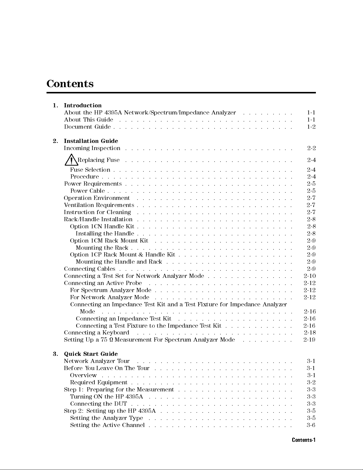
Contents
1. Introduction
About the HP 4395A Network/Spectrum/Impedance Analyzer ......... 1-1
About This Guide .............................. 1-1
Document Guide . . . . . . . . . . . . . . . . . . . . . . . . . . . . . . . 1-2
2. Installation Guide
Incoming Inspection ............................. 2-2
Replacing Fuse ............................. 2-4
Fuse Selection . . . . . . . . . . . . . . . . . . . . . . . . . . . . . . . 2-4
Procedure . . . . . . . . . . . . . . . . . . . . . . . . . . . . . . . . .
Power Requirements . . . . . . . . . . . . . . . . . . . . . . . . . . . . .
Power Cable . . . . . . . . . . . . . . . . . . . . . . . . . . . . . . . .
Operation Environment ...........................
Ventilation Requirements . . . . . . . . . . . . . . . . . . . . . . . . . . .
Instruction for Cleaning .. ...... ...... ...... ...... .
Rack/Handle Installation . . . . . . . . . . . . . . . . . . . . . . . . . . .
Option 1CN Handle Kit . . . . . . . . . . . . . . . . . . . . . . . . . . .
Installing the Handle . . . . . . . . . . . . . . . . . . . . . . . . . . .
Option 1CM Rack Mount Kit ...... ...... ...... ..... .
Mounting the Rack . . . . . . . . . . . . . . . . . . . . . . . . . . . .
Option 1CP Rack Mount & Handle Kit . . . . . . . . . . . . . . . . . . . .
Mounting the Handle and Rack . . . . . . . . . . . . . . . . . . . . . .
Connecting Cables . . . . . . . . . . . . . . . . . . . . . . . . . . . . . .
Connecting a Test Set for Network Analyzer Mode . . . . . . . . . . . . . . .
Connecting an Active Probe .........................
For Spectrum Analyzer Mode . . . . . . . . . . . . . . . . . . . . . . . . 2-12
For Network Analyzer Mode ........................ 2-12
Connecting an Impedance Test Kit and a Test Fixture for Impedance Analyzer
Mode ................................. 2-16
Connecting an Impedance Test Kit ...... ...... ...... .. 2-16
Connecting a Test Fixture to the Impedance TestKit............
Connecting a Keyboard ...........................
Setting Up a 75 Measurement For Spectrum Analyzer Mode .........
2-4
2-5
2-5
2-7
2-7
2-7
2-8
2-8
2-8
2-9
2-9
2-9
2-9
2-9
2-10
2-12
2-16
2-18
2-19
3. Quick Start Guide
Network Analyzer Tour .... ...... ...... ...... .....
Before You Leave On The Tour .......... ...... ...... ..
Overview .................................
Required Equipment . . . . . . . . . . . . . . . . . . . . . . . . . . . . 3-2
Step 1: Preparing for the Measurement . . . . . . . . . . . . . . . . . . . . 3-3
Turning ON the HP 4395A .........................
Connecting the DUT . . . . . . . . . . . . . . . . . . . . . . . . . . . .
Step 2: Setting up the HP 4395A . . . . . . . . . . . . . . . . . . . . . . .
Setting the Analyzer Type .........................
Setting the Active Channel . . . . . . . . . . . . . . . . . . . . . . . . .
3-1
3-1
3-1
3-3
3-3
3-5
3-5
3-6
Contents-1

Selecting the Input . . . . . . . . . . . . . . . . . . . . . . . . . . . . . 3-6
Setting the Frequency Range . . . . . . . . . . . . . . . . . . . . . . . . 3-7
Performing the Automatic Scaling . . . . . . . . . . . . . . . . . . . . . . 3-8
Step 3: Making a Calibration . . . . . . . . . . . . . . . . . . . . . . . . . 3-10
Step 4: Reading a Measurement Result .................... 3-12
Reading a Measured Value by Using Marker ................. 3-12
Step 5: Printing Out the Measurement Result ................. 3-14
Conguring and Connecting a Printer . . . . . . . . . . . . . . . . . . . . 3-14
Making a Hardcopy of the LCD Display ................... 3-14
Spectrum Analyzer Tour ........ ...... ...... ...... . 3-15
Before You Leave On The Tour ........................ 3-15
Overview ................................. 3-15
Required Equipment . . . . . . . . . . . . . . . . . . . . . . . . . . . . 3-16
Step 1: Preparing for a Measurement . . . . . . . . . . . . . . . . . . . . . 3-17
Turning ON the HP 4395A ........ ...... ...... ..... 3-17
Connecting the DUT . . . . . . . . . . . . . . . . . . . . . . . . . . . . 3-17
Step 2: Setting Up the HP 4395A . . . . . . . . . . . . . . . . . . . . . . . 3-18
Setting the Analyzer Type ......................... 3-18
Setting the Active Channel . . . . . . . . . . . . . . . . . . . . . . . . . 3-19
Selecting the Input . . . . . . . . . . . . . . . . . . . . . . . . . . . . . 3-19
Setting the Frequency Range . . . . . . . . . . . . . . . . . . . . . . . .
Step 3: Making a Measurement . . . . . . . . . . . . . . . . . . . . . . . .
Reading the Peak Level Using the Marker . . . . . . . . . . . . . . . . . .
Setting the Resolution Bandwidth to See Low Level Signals
...... ...
Searching for Harmonics Using the Search Function .............
Step 4: Saving and Recalling HP 4395A Settings . . . . . . . . . . . . . . . .
Preparing the Disk . . . . . . . . . . . . . . . . . . . . . . . . . . . . .
Saving HP 4395A Settings .........................
Entering the File Name .........................
Recalling the HP 4395A Settings ......................
Impedance Analyzer Tour ..........................
Before You Leave On The Tour .......................
Overview ................................
Required Equipment . . . . . . . . . . . . . . . . . . . . . . . . . . .
Step 1: Preparing for the Measurement . . . . . . . . . . . . . . . . . . .
3-20
3-22
3-22
3-23
3-25
3-26
3-26
3-27
3-27
3-29
3-31
3-31
3-31
3-32
3-33
Connecting the Impedance TestKit .. ...... ...... ...... 3-33
Turning ON the HP 4395A ........................ 3-33
Setting Up the HP 4395A . . . . . . . . . . . . . . . . . . . . . . . . . . 3-34
Setting the Analyzer Type ...... ...... ..... ...... . 3-34
Activating Channel 1 . . . . . . . . . . . . . . . . . . . . . . . . . . . 3-35
Setting the Sweep Parameters ......................
Setting the Output Level . . . . . . . . . . . . . . . . . . . . . . . . .
Setting the IF Bandwidth . . . . . . . . . . . . . . . . . . . . . . . . .
Setting the Averaging Factor ...... ...... ...... .....
Step 3: Making a Calibration . . . . . . . . . . . . . . . . . . . . . . . .
OPEN Calibration ............................
SHORT Calibration . . . . . . . . . . . . . . . . . . . . . . . . . . . .
LOAD Calibration .... ...... ...... ..... ...... .
3-36
3-37
3-38
3-39
3-41
3-41
3-42
3-43
Step 4: Connecting and Setting Up a Test Fixture .. ...... ...... 3-45
Connecting the xture . . . . . . . . . . . . . . . . . . . . . . . . . . 3-45
Setting the Electrical Length . . . . . . . . . . . . . . . . . . . . . . .
3-45
Fixture Compensation ........ ...... ..... ...... . 3-47
Step 5: Carrying Out Impedance Measurement ........ ...... .
Selecting the Measurement Parameters for Channel 1 ...........
Connecting the DUT . . . . . . . . . . . . . . . . . . . . . . . . . . .
3-49
3-49
3-50
Contents-2

Performing the Automatic Scaling . . . . . . . . . . . . . . . . . . . . . 3-50
Step 6: Switching from Channel 1 to Channel 2 ........ ...... . 3-52
Setting the Averaging Factor for Channel 2 ........ ...... .. 3-53
Step 7: Selecting the measurement parameters for Channel 2 ........ 3-54
Step 8: Dual Channel Display . . . . . . . . . . . . . . . . . . . . . . . . 3-56
4. Front and Rear Panels
Features of HP 4395A ............................ 4-1
Front Panel ................................. 4-1
1. Hardkeys . . . . . . . . . . . . . . . . . . . . . . . . . . . . . . . . 4-2
ACTIVE CHANNEL Block ........................ 4-2
MEASUREMENT Block . . . . . . . . . . . . . . . . . . . . . . . . . . 4-2
SWEEP Key Block . . . . . . . . . . . . . . . . . . . . . . . . . . . . 4-2
MARKER Block ........ ...... ...... ...... ... 4-2
INSTRUMENT STATE Block ....................... 4-2
ENTRY keys . . . . . . . . . . . . . . . . . . . . . . . . . . . . . . . 4-2
2. Softkeys .... ...... ...... ...... ...... .... 4-2
Softkeys that are Joined by Vertical Lines . . . . . . . . . . . . . . . . . 4-3
Softkeys That Toggle Between On and O States . . . . . . . . . . . . . . 4-3
Softkeys that Show Status Indications in Brackets . . . . . . . . . . . . . 4-3
3. HP-IB \
4.
4
Preset
REMOTE
5
Key ........ ...... ...... ...... .....
" Indicator . . . . . . . . . . . . . . . . . . . . . . . .
5. PROBE POWER Connector . . . . . . . . . . . . . . . . . . . . . . . .
4-3
4-3
4-3
6. Analyzer Input Terminals R, A, and B . . . . . . . . . . . . . . . .
7. RF OUT Connector .......... ...... ..... ......
8. DC SOURCE (DC Voltage/Current Output) Connector (Option 001) . . . 4-4
9. Built-in Flexible Disk Drive .......... ...... ...... .
10. LINE Switch . . . . . . . . . . . . . . . . . . . . . . . . . . . . . .
11. Liquid Crystal Display (LCD) ......................
Screen Display . . . . . . . . . . . . . . . . . . . . . . . . . . . . . . . .
1. Active Channel . . . . . . . . . . . . . . . . . . . . . . . . . . . . .
2. Measured Input(s) . . . . . . . . . . . . . . . . . . . . . . . . . . . .
3. Format . . . . . . . . . . . . . . . . . . . . . . . . . . . . . . . . .
4. SCALE/DIV . . . . . . . . . . . . . . . . . . . . . . . . . . . . . . .
5. Reference Level ............................ 4-7
6. Marker Data Readout .......... ...... ...... .... 4-7
7. Marker Statistics and Width Value .................... 4-7
8. Softkey Labels ............................. 4-8
9. PASS/FAIL ...............................
10. Sweep Time . . . . . . . . . . . . . . . . . . . . . . . . . . . . . .
11. Sweep Parameter Span/Stop Value .. ...... ...... .....
12. Power Level . . . . . . . . . . . . . . . . . . . . . . . . . . . . . .
13. CW Frequency . . . . . . . . . . . . . . . . . . . . . . . . . . . . .
14. Video Bandwidth (VBW) ............ ...... ......
15. Input Attenuator ...........................
16. Sweep Parameter Center/Start Value ........ ...... ....
17. RBW/IFBW .............................. 4-9
18. Status Notations . . . . . . . . . . . . . . . . . . . . . . . . . . . . 4-9
19. External Reference ........ ...... ...... ...... 4-10
20. Active Entry Area . . . . . . . . . . . . . . . . . . . . . . . . . . .
21. Message Area .............................
22. Title .................................
Rear Panel Features and Connectors .. ...... ...... ...... .
4-4
4-4
4-5
4-5
4-5
4-5
4-6
4-7
4-7
4-7
4-8
4-8
4-8
4-8
4-8
4-8
4-8
4-8
4-10
4-10
4-10
4-11
Contents-3

1. External Reference Input Connector . . . . . . . . . . . . . . . . . . . 4-11
2. Internal Reference Output Connector .................. 4-11
3. External Program RUN/CONT Input ........ ..... ...... 4-12
4. I/O Port ................................ 4-12
5. Power Cable Receptacle . . . . . . . . . . . . . . . . . . . . . . . . . 4-12
6. HP-IB Interface . . . . . . . . . . . . . . . . . . . . . . . . . . . . . 4-12
7. External Monitor Terminal . . . . . . . . . . . . . . . . . . . . . . . . 4-12
8. Parallel Interface ............................ 4-12
9. 24-bit I/O Port ............................. 4-12
10. mini-DIN Keyboard Connector ...... ...... ...... ... 4-12
11. Test Set I/O Interface ....................... 4-13
12. Gate Output (Option 1D6 Only) . . . . . . . . . . . . . . . . . . . . . 4-13
13. External Trigger Input . . . . . . . . . . . . . . . . . . . . . . . . . 4-13
14. Reference Oven Output (Option 1D5 Only) . . . . . . . . . . . . . . . . 4-13
5. Preparations for Measurements
Selecting an appropriate connection of DUT . . . . . . . . . . . . . . . . . . 5-1
For Network Measurement . . . . . . . . . . . . . . . . . . . . . . . . . 5-1
Connecting DUT for Directional Transmission Characteristic Measurement . . 5-1
Connecting DUT for Directional Transmission and Reection Characteristics
Measurement . . . . . . . . . . . . . . . . . . . . . . . . . . . . .
Connecting DUT for Bi-directional Transmission and Reection Characteristics
(Four S Parameters) Measurement . . . . . . . . . . . . . . . . . . .
Connecting DUT for Transmission Characteristic Measurement When the
Output Signal is in a Circuit . . . . . . . . . . . . . . . . . . . . . .
Connecting DUT for Transmission Characteristic Measurement When the Input
and Output Signals are in a Circuit .. ...... ...... ....
For Spectrum Measurement .. ...... ...... ..... .....
Connecting DUT When Directly Measuring the Signal .. ...... ...
Connecting DUT When Measuring the Signal in a Circuit . . . . . . . . . .
For Impedance Measurement (Option 010) . . . . . . . . . . . . . . . . . .
Connecting the Impedance TestKit .. ...... ...... ......
Presetting HP 4395A . . . . . . . . . . . . . . . . . . . . . . . . . . . . .
5-2
5-2
5-3
5-5
5-6
5-6
5-6
5-8
5-8
5-9
6. Setting and Optimizing Measurement Conditions
Selecting the Analyzer Mode .......... ...... ...... ... 6-2
Selecting the Active Channel . . . . . . . . . . . . . . . . . . . . . . . . . 6-2
Dual Channel Display ............................ 6-3
Setting Up the Trigger System ........ ...... ...... .... 6-4
Setting Up the Trigger System .......................
Using the External Trigger . . . . . . . . . . . . . . . . . . . . . . . . .
Setting the Trigger Signal Polarity . . . . . . . . . . . . . . . . . . . . .
Generating a Trigger Event on Each Measurement Point (NA, ZA Mode) . . . . 6-5
Setting the Sweep Conditions . . . . . . . . . . . . . . . . . . . . . . . . .
Selecting the Sweep Mode .........................
Selecting the Sweep Type .. ...... ...... ...... .....
Using the Power Sweep Function (NA, ZA Mode) .............. 6-7
Selecting the Input Port/Measurement Parameter ............... 6-7
To Select the Input Port in NA Mode .................... 6-7
With the T/R Test Set .. ...... ...... ...... ......
With the S-Parameter Test Set .. ...... ...... ...... ..
To Select the Input Port in SA Mode ........ ...... ......
To Select the Measurement Parameter in ZA mode . . . . . . . . . . . . . .
Selecting the Measurement Format (NA, ZA Mode) . . . . . . . . . . . . . . .
Contents-4
6-4
6-4
6-5
6-6
6-6
6-6
6-7
6-7
6-8
6-8
6-10
Selecting the Measurement Format in NA Mode ............... 6-10
Displaying the Trace as a Smith Chart (NA, ZA Mode) ........ .... 6-10
How To Change Marker Readout Format (NA, ZA Mode) ........... 6-11
Using the Impedance Conversion Function (NA Mode) ............ 6-11
To Display Phase beyond6180 Degrees (NA, ZA Mode) ........... 6-12
Using the Complex Plane Format (ZA Mode) . . . . . . . . . . . . . . . . . 6-12
Displaying R-X in the Complex Plane ................... 6-12
Using the Marker ............................ 6-13
Adjusting the Scale Setting . . . . . . . . . . . . . . . . . . . . . . . . 6-13
Selecting the Display Unit .......................... 6-14
Selecting the Display Unit in SA Mode .. ...... ...... ..... 6-14
Selecting the Phase Unit (NA, ZA Mode) .................. 6-14
Setting the Frequency Range . . . . . . . . . . . . . . . . . . . . . . . . . 6-15
Setting the Center Frequency . . . . . . . . . . . . . . . . . . . . . . . . 6-15
Setting the Marker Position to Center . . . . . . . . . . . . . . . . . . . . 6-15
Setting the Maximum Peak to Center .... ...... ...... .... 6-17
Change the Center Frequency by the Specied Step Size . . . . . . . . . . . 6-17
Example: Displaying Harmonics (SA Mode) ................ 6-18
Setting the Frequency Span ........................ 6-19
Narrowing the Span Setting (SA Mode) ................... 6-20
Setting the Frequency Range to Full Span . . . . . . . . . . . . . . . .
Setting the Sweep Parameters Using
4
Start
5
and
4
Stop
5
............
Zooming ToaPart of the Trace . . . . . . . . . . . . . . . . . . . . . .
Change the Zooming Factor . . . . . . . . . . . . . . . . . . . . . . .
Displaying a Zoomed Trace on the Other Channel ...... ......
Adjusting the Scale and Reference ......................
6-20
6-21
6-22
6-22
6-22
6-23
Automatically Adjusting the Scale and Reference (NA, ZA Mode) ...... 6-23
Manually Adjusting the Scale and Reference (NA, ZA Mode)
Setting the Reference (SA Mode) .....................
Using the Numeric Keys ...... ...... ...... ......
Using the Marker .. ...... ...... ...... ...... .
Changing the Scale per Division (SA Mode) ...... ...... ....
Setting the IF/Resolution/Video Bandwidth .. ...... ...... ....
Setting the IF Bandwidth (NA, ZA Mode) ...... ...... ..... .
Setting the IF Bandwidth to Auto Mode . . . . . . . . . . . . . . . . . .
...... .. 6-23
6-24
6-24
6-24
6-25
6-26
6-26
6-26
Setting the Resolution Bandwidths (SA Mode) . . . . . . . . . . . . . . . . 6-27
Setting the Resolution Bandwidth to Auto Mode . . . . . . . . . . . . . . 6-27
Setting the Video Bandwidth (SA Mode) . . . . . . . . . . . . . . . . . . . 6-28
Resetting the Video Bandwidth . . . . . . . . . . . . . . . . . . . . . 6-28
7. Calibration
Calibration Required for the Network Analyzer Mode .............
To Select an Appropriate Calibration Method ................
Performing a Response Calibration .....................
Performing a Response & Isolation Calibration . . . . . . . . . . . . . . . .
Performing an S11 1-Port Calibration ....................
Performing an S22 1-Port Calibration ....................
Performing a Full 2-Port Calibration . . . . . . . . . . . . . . . . . . . . .
Performing a 1-Path 2-Port Calibration ................... 7-8
Selecting the Calibration Kit ........................ 7-10
Customizing the User Dened Calibration Kit ...... ..... .....
Dening the Standard Denition .....................
Step 1: Preparation ...... ...... ...... ...... ..
Step 2: Opening the Dene Standard Menu ...............
Step 3: Entering C Parameters .....................
7-1
7-1
7-2
7-2
7-4
7-5
7-6
7-10
7-10
7-10
7-10
7-11
Contents-5
Step 4: Entering OFFSET Parameters . . . . . . . . . . . . . . . . . . 7-11
Step 5: Entering a Standard Class Label . . . . . . . . . . . . . . . . . 7-11
Step 6: Completing the Denition of a Calibration Kit .......... 7-11
Dening a Class Assignment ....................... 7-12
Step 1: Preparing for the Class Assignment ............... 7-12
Step 2: Specifying the Standard Class . . . . . . . . . . . . . . . . . . 7-12
Step 3: Creating the Standard Class Label . . . . . . . . . . . . . . . . 7-13
Labeling and Saving Calibration Kit . . . . . . . . . . . . . . . . . . . 7-13
Verifying the Denition of the User-Dened Calibration Kit . . . . . . . . 7-13
Calibration Required for the Impedance Analyzer Mode .. ...... .... 7-14
OPEN/SHORT/LOAD Calibration ...................... 7-14
Calibration Procedure ........ ...... ...... ...... 7-14
Connecting the Test Fixture ........................ 7-15
Setting the Electrical Length of the Test Fixture . . . . . . . . . . . . . . . 7-17
Setting the User Dened Fixture ...................... 7-17
Performing Fixture Compensation . . . . . . . . . . . . . . . . . . . . . . 7-18
Selecting the Calibration Kit ........................ 7-19
Dening a Custom Fixture Compensation Kit .. ...... ...... .. 7-19
Step 1: Opening the Fixture Compensation Kit Modication Menu .... . 7-19
Step 2: Specifying Parameter Values ...... ...... ...... . 7-20
Step 3: Specifying the Standard Label ..................
8. Analyzing the Measurement Results
Interpreting the Trace ........ ...... ...... ...... ..
To Read a Value Using the Marker ...... ...... ...... ...
Improving the Readout Resolution (SA Mode) ...... ...... ...
To Select Marker Readout Unit (SA Nide) .................
To Use the Sub-markers ........ ...... ...... ......
To Use the1Marker . . . . . . . . . . . . . . . . . . . . . . . . . . . .
To Search for a Point that has the Target Value (NA, SA Mode) ........ 8-5
To Search for the Peak-to-Peak of Ripples Using the Statistics Function .... 8-7
Step 1: To Specify the Search Range ...................
Step 2: To Search For the Ripple .....................
To Search for a Single Peak on the Trace ..................
To Search for Multiple Peaks ........................
To Dene the Peak for Search (To Ignore Unnecessary Peaks) . . . . . . . . . 8-10
Dening the Peak Slope to Ignore the Relatively Broad Peaks (NA, ZA Mode) 8-10
Entering Directly ........................... 8-10
Using the Marker .. ...... ...... ..... ...... .. 8-10
Dening Peak Height (SA Mode) .. ...... ...... ...... . 8-11
Specifying the Peak Threshold to Ignore the Absolutely Small P
eaks .... 8-11
Entering Directly ...........................
Using the Marker .. ...... ...... ..... ...... ..
To Specify the Search Range ........................
Using the Marker ............................
Using the 1Marker . . . . . . . . . . . . . . . . . . . . . . . . . . . .
To Use the Trace Memory ...... ...... ...... ...... ..
To Store the Trace into the Trace Memory . . . . . . . . . . . . . . . . . .
To Display Memory Traces ......................... 8-14
To Use the Trace Math Function .. ...... ..... ...... .... 8-15
To Turn O the Data Math Function ....................
To Multiply the Trace .. ...... ...... ...... ...... .
To Clear a Multiplied Trace . . . . . . . . . . . . . . . . . . . . . . . . .
To Overlay Multiple Traces . . . . . . . . . . . . . . . . . . . . . . . . . .
To Store the Trace into the Overlay Trace . . . . . . . . . . . . . . . . . .
7-20
8-2
8-2
8-3
8-3
8-4
8-5
8-7
8-7
8-8
8-9
8-11
8-11
8-12
8-12
8-12
8-14
8-14
8-15
8-15
8-15
8-16
8-16
Contents-6
To Clear the Overlay Traces ........................ 8-16
To Print . . . . . . . . . . . . . . . . . . . . . . . . . . . . . . . . . . . 8-17
To Print Out a Display Image . . . . . . . . . . . . . . . . . . . . . . . . 8-17
To See or Print a Measured Value List . . . . . . . . . . . . . . . . . . . . 8-17
To Print an Analyzer Setting ........................ 8-17
To Save and Recall the Settings and Data ........ ...... ..... 8-19
To Save an Analyzer Setting or Measurement Data . . . . . . . . . . . . . . 8-19
Specifying the Data Format . . . . . . . . . . . . . . . . . . . . . . . . 8-20
Specifying a Data Array Type ...................... 8-20
To Recall a Saved Analyzer Setting ..................... 8-20
To Save a Display Image to a TIFF File ................... 8-21
To Save Measured Data for a Spreadsheet . . . . . . . . . . . . . . . . . . 8-21
To Copy a File between Floppy Disk and Memory Disk . . . . . . . . . . . . 8-22
To Initialize a Disk for Use .......... ...... ...... ... 8-22
To Initialize the Memory Disk for Use . . . . . . . . . . . . . . . . . . . . 8-23
To Back Up the Memory Disk . . . . . . . . . . . . . . . . . . . . . . . . 8-23
Typical Network Measurement Techniques .. ...... ...... .... 8-24
Measuring 3 dB Bandwidth Using the Width Function ............ 8-25
Measuring Electrical Length ........ ...... ...... .... 8-26
Setting the Velocity Factor of a Cable . . . . . . . . . . . . . . . . . . . 8-27
Measuring Phase Deviation . . . . . . . . . . . . . . . . . . . . . . . . .
Deviation from the Linear Phase .......... ...... .....
Group Delay . . . . . . . . . . . . . . . . . . . . . . . . . . . . . . .
Setting the Group Delay Aperture ...................
Compensating for the Electrical Delay Caused by an Extension Cable . . . . .
If the Electrical Delay of the Extension Cable is Known
...... ....
If the Electrical Delay of the Extension Cable is Unknown . . . . . . . . .
Measuring the Electrical Length of a Cable ...............
Reection of a Opened or Shorted Cable ................
Typical Spectrum Measurement Techniques ..................
Measuring the Noise Level .... ...... ...... ...... ...
Converting to a Dierent Unit of Equivalent Noise Bandwidth
...... . 8-34
Measuring the Carrier to Noise Ratio ...... ...... ...... ..
Time Gated Spectrum Analysis .......................
Gate Trigger Mode . . . . . . . . . . . . . . . . . . . . . . . . . . . .
8-28
8-28
8-28
8-29
8-30
8-30
8-31
8-31
8-31
8-33
8-34
8-36
8-37
8-37
Edge Mode .............................. 8-37
Level Mode .............................. 8-38
RBW Filter Response Time . . . . . . . . . . . . . . . . . . . . . . . . 8-39
Performing Time Gated Spectrum Analysis ................ 8-40
Step 1: Determining the Gate Trigger Parameters ...... ...... 8-40
Step 2: Connecting the Gate Trigger Source . . . . . . . . . . . . . . .
Step 3: Setting the Center and Span Frequency .............
Step 4: Adjusting the Gate Trigger .......... ...... ...
8-42
8-42
8-42
Setting the RBW/VBW and Using the Averaging Function . . . . . . . . . . 8-43
Setting the Resolution Bandwidth . . . . . . . . . . . . . . . . . . . .
Setting the Video Bandwidth (VBW) ..................
Measuring the Spectrum .. ...... ...... ...... ....
Measuring Zero Span . . . . . . . . . . . . . . . . . . . . . . . . . . . .
8-43
8-44
8-45
8-46
Reading Transition Time Using the Marker ................ 8-47
Tracking Unstable Harmonics Using the Search Track Function . . . . . . . . 8-49
Typical Impedance Measurement Techniques .... ...... ...... .
Applying DC Bias .. ...... ...... ...... ..... ....
Setting the Upper Limit for DC Bias . . . . . . . . . . . . . . . . . . . .
Setting up and Applying Output Voltage/Current . . . . . . . . . . . . . .
Equivalent Circuit Analysis . . . . . . . . . . . . . . . . . . . . . . . . .
8-50
8-50
8-51
8-51
8-52
Contents-7
Menus Associated with Equivalent Circuit Analysis ............ 8-52
Equivalent Circuit Menu . . . . . . . . . . . . . . . . . . . . . . . . 8-52
Select Equivalent Circuit Menu . . . . . . . . . . . . . . . . . . . . . 8-53
Dene Equivalent Circuit Parameter Menu ............... 8-53
Using the Equivalent Circuit Analysis Function ...... ...... .. 8-55
Calculating Approximate Values of Equivalent Circuit Constants ..... 8-55
Simulating a Trace from the Equivalent Circuit Parameters . . . . . . . . 8-55
Determining Q Value Using the Width Search Function . . . . . . . . . . . . 8-56
Widths Menu ............................... 8-56
Width Value Menu . . . . . . . . . . . . . . . . . . . . . . . . . . . . . 8-56
Using the Anti-Resonance Point . . . . . . . . . . . . . . . . . . . . . . 8-57
Using the Resonance Point .. ...... ...... ..... ..... 8-57
Using the Admittance Chart ....................... 8-57
Port Extension . . . . . . . . . . . . . . . . . . . . . . . . . . . . . . . 8-58
9. Advanced Techniques for Optimizing Measurements
Reducing Sweep Time (Using List Sweep) ................... 9-2
Planning the sweep list .. ...... ...... ...... ...... 9-2
Editing a Sweep List . . . . . . . . . . . . . . . . . . . . . . . . . . . . 9-3
To Modify or Delete the Segment . . . . . . . . . . . . . . . . . . . . . 9-4
Executing the List Sweep .. ...... ...... ...... .....
Improving Dynamic Range (NA Mode) . . . . . . . . . . . . . . . . . . . . .
Adjusting the IF Bandwidth .... ...... ...... ..... ...
Using List Sweep .. ...... ...... ...... ...... ...
Performing GO/NO-GO Test of a Filter (using limit line) . . . . . . . . . . . . .
Planning the Limit Lime ..........................
Editing a Limit Line Table .........................
To Modify or Delete the Segment . . . . . . . . . . . . . . . . . . . . .
Executing a Limit Line Test ........................
To Make a Limit Line Test Active .....................
To Beep When the Limit Test is Failed . . . . . . . . . . . . . . . . . . .
To Oset the Limit Line ..........................
Stabilizing the Trace . . . . . . . . . . . . . . . . . . . . . . . . . . . . .
To Stop the Sweep . . . . . . . . . . . . . . . . . . . . . . . . . . . . .
To Use the Averaging Function . . . . . . . . . . . . . . . . . . . . . . .
To Use Maximum or Minimum Hold Function ................ 9-13
To Capture an Unstable Signal Using Signal Track .............. 9-14
9-5
9-6
9-6
9-7
9-8
9-9
9-9
9-10
9-10
9-10
9-11
9-12
9-13
9-13
9-13
10. Examples of Applications
Measuring Transmission Characteristics of a Filter (NA Mode) ......... 10-2
Measurement Setup ............................
Connection ...............................
Analyzer Settings .. ...... ...... ...... ...... ..
Performing Calibration . . . . . . . . . . . . . . . . . . . . . . . . . .
Measurement ..............................
Read Out Insertion Loss Using the Marker . . . . . . . . . . . . . . . . . .
6 dB Bandwidth . . . . . . . . . . . . . . . . . . . . . . . . . . . . . .
Ripple . . . . . . . . . . . . . . . . . . . . . . . . . . . . . . . . . . .
Measuring Phase Response . . . . . . . . . . . . . . . . . . . . . . . . . 10-5
Using the Expanded Phase Mode .... ...... ..... ...... . 10-6
Reection Measurement (NA) . . . . . . . . . . . . . . . . . . . . . . . . .
Measurement Setup ............................
Connection ...............................
Analyzer Settings .. ...... ...... ...... ...... ..
Performing Calibration . . . . . . . . . . . . . . . . . . . . . . . . . .
Contents-8
10-2
10-2
10-2
10-3
10-3
10-3
10-3
10-4
10-7
10-8
10-8
10-8
10-8

Measurement .............................. 10-9
Return Loss and Reection Coecient ................... 10-9
Standing Wave Ratio (SWR) . . . . . . . . . . . . . . . . . . . . . . . . . 10-10
S-Parameters Measurement . . . . . . . . . . . . . . . . . . . . . . . . . 10-11
Data Readout Using the Marker . . . . . . . . . . . . . . . . . . . . . . 10-11
Impedance Measurement . . . . . . . . . . . . . . . . . . . . . . . . . . 10-12
Admittance Measurement .. ...... ...... ...... ..... 10-13
Gain Compression Measurement (NA) . . . . . . . . . . . . . . . . . . . . . 10-14
Measurement Setup ............................ 10-14
Connection ............................... 10-14
Analyzer Settings ............................ 10-15
Performing Calibration . . . . . . . . . . . . . . . . . . . . . . . . . . 10-15
Measurement .............................. 10-15
Absolute Output Level Measurement .................... 10-16
AM Signal Measurement (SA) . . . . . . . . . . . . . . . . . . . . . . . . . 10-18
Test Signal . . . . . . . . . . . . . . . . . . . . . . . . . . . . . . . . . 10-18
Measurement Setup ............................ 10-18
Connection ............................... 10-18
Analyzer Settings ............................ 10-18
Carrier Amplitude and Frequency Measurement Using the Marker ...... 10-18
Modulating Frequency and Modulation Index Measurement Using 1Marker
FM Signal Measurement (SA) . . . . . . . . . . . . . . . . . . . . . . . . .
Test Signal . . . . . . . . . . . . . . . . . . . . . . . . . . . . . . . . .
Measurement Setup ............................
Connection ...............................
Analyzer Settings ............................
Frequency Deviation of Wide Band FM Signal . . . . . . . . . . . . . . . .
Frequency Deviation . . . . . . . . . . . . . . . . . . . . . . . . . . .
Carrier Level and Modulating Frequency ...... ...... .....
Evaluation of a Chip Capacitor (ZA Mode) . . . . . . . . . . . . . . . . . . .
Measurement Setup ............................
Connection ...............................
Analyzer Settings ............................
Calibration ...............................
Connecting the Test Fixture .......................
.. 10-19
10-21
10-21
10-21
10-21
10-21
10-21
10-21
10-22
10-24
10-24
10-24
10-24
10-25
10-25
Setting the Electrical Length of the Test Fixture . . . . . . . . . . . . . . 10-26
Fixture Compensation ...... ...... ...... ...... .. 10-26
Capacitance and Dissipation Factor under Swept Frequency .... ..... 10-27
Setting Measurement Parameters ..................... 10-27
Measurement .............................. 10-27
jZj
and(Phase) under Swept Frequency ...... ...... ......
Equivalent Circuit Analysis . . . . . . . . . . . . . . . . . . . . . . . . .
Evaluation of a Crystal Resonator (ZA Mode) .. ...... ...... ...
Measurement Setup ............................
Connection ...............................
Analyzer Settings ............................
Calibration ...............................
Connecting the Test Fixture .......................
10-28
10-29
10-31
10-31
10-31
10-31
10-31
10-31
Setting the Electrical Length of the Test Fixture . . . . . . . . . . . . . . 10-31
Fixture Compensation ...... ...... ...... ...... .. 10-32
Setting Measurement Parameters .....................
Measurement ..............................
10-32
10-32
Readout of Resonance Frequency (Fr) and Crystal Impedance (CI) ...... 10-33
Equivalent Circuit Analysis . . . . . . . . . . . . . . . . . . . . . . . . .
Admittance Chart .............................
10-33
10-35
Contents-9

Using the Marker .. ...... ...... ..... ...... .... 10-35
Evaluation of a Varactor Diode - DC Bias Sweep Using List Sweep Function (ZA
Mode) .................................. 10-36
Measurement Setup ............................ 10-36
Connection ............................... 10-36
Analyzer Settings .. ...... ...... ...... ...... .. 10-36
Dening the Sweep List ......................... 10-36
Calibration .. ...... ...... ...... ...... ..... 10-37
Connecting the Test Fixture ....................... 10-38
Setting the Electrical Length of the Test Fixture . . . . . . . . . . . . . . 10-38
Fixture Compensation ........ ...... ..... ...... . 10-38
Measuring Capacitance under DC Bias Conditions .............. 10-38
11. Specications and Supplemental Characteristics
Network Measurement . . . . . . . . . . . . . . . . . . . . . . . . . . . . 11-1
Source Characteristics .......... ...... ...... ..... 11-1
Frequency Characteristics ........................ 11-1
Output Characteristics . . . . . . . . . . . . . . . . . . . . . . . . . . 11-1
Receiver Characteristics .. ...... ...... ...... ...... 11-3
Input Characteristics . . . . . . . . . . . . . . . . . . . . . . . . . . . 11-3
Magnitude Characteristics ........................
Phase Characteristics ..........................
Group Delay Characteristics ........................
Sweep Characteristics ...........................
Measurement Throughput1...... ...... ...... ...... .
Spectrum Measurement ...........................
Frequency Characteristics .. ...... ...... ...... .....
Amplitude Characteristics .........................
Sweep Characteristics ...........................
Input Characteristics . . . . . . . . . . . . . . . . . . . . . . . . . . . .
Specications when Option 1D6 Time-Gated spectrum analysis is installed . . .
Specications when Option 1D7 50 to 75 Input Impedance Conversion is
installed . . . . . . . . . . . . . . . . . . . . . . . . . . . . . . . .
HP 4395A Option 010 Impedance Measurement ................
Measurement Functions ..........................
Display Formats ...... ...... ...... ...... ...... 11-14
Sweep Parameters . . . . . . . . . . . . . . . . . . . . . . . . . . . . . 11-14
IF Bandwidth .......... ...... ...... ...... ... 11-14
Calibration ................................ 11-14
Measurement Port Type .......................... 11-14
Output Characteristics . . . . . . . . . . . . . . . . . . . . . . . . . . .
Measurement Basic Accuracy (Supplemental Performance Characteristics) . . . . 11-16
jZj-
Accuracy .. ...... ...... ...... ...... ....
jYj-
Accuracy ..............................
R-XAccuracy (Depends on D) . . . . . . . . . . . . . . . . . . . . . . .
G-BAccuracy (Depends on D) . . . . . . . . . . . . . . . . . . . . . . .
DAccuracy ................................
LAccuracy (Depends on D) . . . . . . . . . . . . . . . . . . . . . . . . .
CAccuracy (Depends on D) . . . . . . . . . . . . . . . . . . . . . . . . . 11-19
Common to Network/Spectrum/Impedance Measurement . . . . . . . . . . . . 11-20
Display ..................................
Marker ..................................
Hard copy . . . . . . . . . . . . . . . . . . . . . . . . . . . . . . . . .
Storage ..................................
HP-IB . . . . . . . . . . . . . . . . . . . . . . . . . . . . . . . . . . .
11-4
11-5
11-6
11-6
11-6
11-7
11-7
11-8
11-12
11-12
11-13
11-13
11-14
11-14
11-14
11-17
11-18
11-18
11-18
11-19
11-19
11-20
11-20
11-20
11-20
11-20
Contents-10
Printer parallel port ............................ 11-21
Option 001 DC Voltage/Current Source ................... 11-21
Probe Power .. ...... ...... ...... ...... ..... 11-21
Specications When HP Instrument BASIC Is Operated . . . . . . . . . . . . 11-21
General Characteristics . . . . . . . . . . . . . . . . . . . . . . . . . . . 11-24
Input and Output Characteristics ...... ...... ...... ... 11-24
Internal Clock . . . . . . . . . . . . . . . . . . . . . . . . . . . . . . 11-25
Operation Conditions . . . . . . . . . . . . . . . . . . . . . . . . . . . . 11-25
Non-operation Conditions .. ...... ...... ...... ..... 11-26
Others .. ...... ...... ...... ...... ...... .. 11-26
Furnished Accessories ............................ 11-28
System Performance at Network Measurement ................ 11-29
Typical System Performance ......................... 11-29
Introduction . . . . . . . . . . . . . . . . . . . . . . . . . . . . . . . . 11-29
Comparison of Typical Error-Corrected Measurement Uncertainty ...... 11-29
Reection Uncertainty of a One-Port Device . . . . . . . . . . . . . . . . . 11-30
Reection Uncertainty of a Two-Port Device ................ 11-31
Transmission Uncertainty of a Low-Loss Device ........ ...... . 11-32
Transmission Uncertainty of a Wide Dynamic Range Device ......... 11-33
Types of Residual Measurement Errors .... ...... ...... .... 11-34
Residual Systematic Errors . . . . . . . . . . . . . . . . . . . . . . . . .
Residual Random Errors ...... ...... ...... ...... ..
Residual Drift Errors . . . . . . . . . . . . . . . . . . . . . . . . . . . .
System Error Model .. ...... ...... ...... ...... ...
Reection Uncertainty Equations . . . . . . . . . . . . . . . . . . . . . . .
Total Reection Magnitude Uncertainty (E
Total Reection Phase Uncertainty (E
rp
) ........ ...... ..
rm
)...................
Transmission Uncertainty Equations .....................
Total Transmission Magnitude Uncertainty (E
Total Transmission Phase Uncertainty (E
tp
)...............
tm
) .................
Dynamic Accuracy . . . . . . . . . . . . . . . . . . . . . . . . . . . . . .
Magnitude Dynamic Accuracy .. ...... ...... ...... ...
11-34
11-34
11-34
11-35
11-36
11-36
11-36
11-37
11-37
11-37
11-38
11-38
Determining Relative Magnitude Dynamic Accuracy Error Contribution . . . . 11-38
Phase Dynamic Accuracy . . . . . . . . . . . . . . . . . . . . . . . . . .
11-39
Determining Relative Phase Dynamic Accuracy Error Contribution .. .... 11-39
Dynamic Accuracy Error Contribution . . . . . . . . . . . . . . . . . . . . 11-40
Dynamic Accuracy Error Contribution . . . . . . . . . . . . . . . . . . . . 11-41
Dynamic Accuracy Error Contribution . . . . . . . . . . . . . . . . . . . . 11-42
Eects of Temperature Drift ......................... 11-43
Temperature Drift with S11One-Port Calibration . . . . . . . . . . . . . . . 11-44
Temperature Drift with Full Two-Port Calibration ..............
11-45
System performance with Dierent Test Sets and Connector Types .. ..... 11-46
Determining Expected System performance . . . . . . . . . . . . . . . . . .
Procedures ........ ...... ...... ..... ...... .
11-53
11-53
12. Accessories and Options
Options Available ..............................
DC SOURCE (Option 001) . . . . . . . . . . . . . . . . . . . . . . . . . .
High Stability Frequency Reference (Option 1D5) .... ...... .... 12-1
Time-Gated Spectrum Analyzer (Option 1D6) ................ 12-1
50 to 75 Input Impedance Conversion (Option 1D7)
...... ......
Impedance Measurement Function (Option 010) ...............
Handle Kit (Option 1CN) . . . . . . . . . . . . . . . . . . . . . . . . . .
Rack Mount Kit (Option 1CM) . . . . . . . . . . . . . . . . . . . . . . . .
Rack Mount and Handle Kit (Option 1CP) ..................
12-1
12-1
12-1
12-1
12-1
12-1
12-1
Contents-11
Measurement accessories available ...................... 12-2
Test Sets ................................. 12-2
HP 87511A/B S Parameter Test Set .................... 12-2
HP 87512A/B Transmission/Reection TestSet........ ...... . 12-2
Active Probes ............................... 12-2
HP 41800A Active Probe (5 Hz to 500 MHz) .......... ...... 12-2
HP 41802A 1 M Input Adapter (5 Hz to 100 MHz) . . . . . . . . . . . . . 12-2
HP 1141A Dierential Probe .......... ...... ...... . 12-2
Power Splitters .............................. 12-2
HP 11850C,D Three-way Power Splitters .. ...... ...... ... 12-2
HP 11667A Power Splitter ...... ...... ...... ..... . 12-2
Calibration Kits .............................. 12-3
Cables .................................. 12-3
HP 11857D 7 mm Test Port Return Cable Set ............... 12-3
HP 11857B 75 Type-N Test Port Return Cable Set .. ...... .... 12-3
HP 11851B 50 Type-N RF Cable Set . . . . . . . . . . . . . . . . . . . 12-3
BNC Cables ............................... 12-3
Adapters ................................. 12-3
HP 11852B 50 to 75 Minimum Loss Pad (DC to 2 GHz) ...... ... 12-3
Adapter Kits . . . . . . . . . . . . . . . . . . . . . . . . . . . . . . . 12-3
System accessories available .........................
Printer ..................................
HP-IB cable ...... ...... ...... ...... ...... ..
External Monitors .............................
12-5
12-5
12-5
12-5
A. Basic Measurement Theory
System Overview ..............................
Data Processing ...............................
Overview .................................
Data Processing for Network Measurement .... ...... ...... .
Digital Filter . . . . . . . . . . . . . . . . . . . . . . . . . . . . . . .
Ratio Calculations ............................
Frequency Characteristics Correction by Corrective Data Arrays .... .. A-5
Averaging . . . . . . . . . . . . . . . . . . . . . . . . . . . . . . . .
Raw Data Arrays ............................
Calibration Coecient Arrays ...... ...... ...... .... A-5
Data Arrays . . . . . . . . . . . . . . . . . . . . . . . . . . . . . . . A-5
Memory Arrays ............................. A-5
Electrical Delay and Phase Oset . . . . . . . . . . . . . . . . . . . . . A-5
Conversion .. ...... ...... ...... ...... ..... A-5
Format .................................
Data Hold . . . . . . . . . . . . . . . . . . . . . . . . . . . . . . . .
Data Math . . . . . . . . . . . . . . . . . . . . . . . . . . . . . . . .
Data Trace Arrays . . . . . . . . . . . . . . . . . . . . . . . . . . . .
Memory Trace Arrays .... ...... ...... ...... ....
Scaling .................................
Data Processing for Spectrum Measurement . . . . . . . . . . . . . . . . .
Decimation Windowing . . . . . . . . . . . . . . . . . . . . . . . . . .
Fast Fourier Transform (
fft
) .... ...... ...... ...... . A-7
Absolute Squared (ABS2)......................... A-8
Video Averaging . . . . . . . . . . . . . . . . . . . . . . . . . . . . .
Detection . . . . . . . . . . . .. ...... ...... ...... .
Attenuator Adjustment . . . . . . . . . . . . . . . . . . . . . . . . . .
Averaging . . . . . . . . . . . . . . . . . . . . . . . . . . . . . . . .
Frequency Characteristics Level Correction ........ ...... ..
A-2
A-3
A-3
A-3
A-4
A-4
A-5
A-5
A-6
A-6
A-6
A-6
A-6
A-6
A-7
A-7
A-8
A-8
A-8
A-8
A-8
Contents-12

Raw Data Arrays ............................ A-8
Memory Arrays ............................. A-8
Format/Unit conversion ......................... A-8
Data Hold . . . . . . . . . . . . . . . . . . . . . . . . . . . . . . . . A-8
Data Math . . . . . . . . . . . . . . . . . . . . . . . . . . . . . . . . A-8
Data Trace Array ...... ...... ...... ..... ..... A-9
Memory Trace Array . . . . . . . . . . . . . . . . . . . . . . . . . . . A-9
Scaling ................................. A-9
Data Processing for Impedance Measurement ........ ...... .. A-10
Digital Filter . . . . . . . . . . . . . . . . . . . . . . . . . . . . . . . A-10
Voltage/Current Ratio .......................... A-10
I-V to Reection Coecient Conversion . . . . . . . . . . . . . . . . . . A-11
Calibration Coecient Arrays/Calibration ................. A-11
Averaging . . . . . . . . . . . . . . . . . . . . . . . . . . . . . . . . A-11
Raw Data Arrays ............................ A-11
Fixture Compensation Coecient Arrays/Fixture Compensation ...... A-11
Data Arrays . . . . . . . . . . . . . . . . . . . . . . . . . . . . . . . A-11
Memory Arrays ............................. A-11
Conversion ............................... A-11
Format ................................. A-11
Data Hold . . . . . . . . . . . . . . . . . . . . . . . . . . . . . . . .
Data Math . . . . . . . . . . . . . . . . . . . . . . . . . . . . . . . .
Data Trace Array ...... ...... ...... ..... .....
Memory Trace Array . . . . . . . . . . . . . . . . . . . . . . . . . . .
Scaling .................................
Network Measurement Basics . . . . . . . . . . . . . . . . . . . . . . . . .
S-parameters ........ ...... ...... ...... .....
Conversion Function . . . . . . . . . . . . . . . . . . . . . . . . . . . .
Smith Chart . . . . . . . . . . . . . . . . . . . . . . . . . . . . . . . .
Polar Chart ........ ...... ...... ...... ..... .
Electrical Delay .. ...... ...... ...... ...... ....
Averaging (Sweep Averaging) . . . . . . . . . . . . . . . . . . . . . . . .
IF Band Reduction . . . . . . . . . . . . . . . . . . . . . . . . . . . . .
Group Delay . . . . . . . . . . . . . . . . . . . . . . . . . . . . . . . .
Spectrum Measurement Basics ........................
A-11
A-12
A-12
A-12
A-12
A-13
A-13
A-14
A-15
A-15
A-15
A-16
A-16
A-16
A-19
Detection Modes . . . . . . . . . . . . . . . . . . . . . . . . . . . . . . A-19
Positive and Negative Peak Modes .................... A-19
Sample Mode .............................. A-19
Swept Spectrum Analyzers versus FFT Analyzers .... ...... .... A-19
Selectivity of the RBW . . . . . . . . . . . . . . . . . . . . . . . . . . . A-21
Noise measurement ........ ...... ...... ...... ..
Noise Format and Marker Noise Form.... ...... ...... ...
Sample Detection Mode for Noise Measurement ..............
VBW for Noise Measurement . . . . . . . . . . . . . . . . . . . . . . .
Impedance Measurement Basics . . . . . . . . . . . . . . . . . . . . . . . .
I-V Measurement Method . . . . . . . . . . . . . . . . . . . . . . . . . .
Basic Concept of I-V Method .......... ...... ..... ...
A-22
A-22
A-22
A-22
A-23
A-23
A-23
How This Is Dierent From Impedance Conversion in the Network Analyzer
Mode ................................. A-23
Impedance Measurement Scheme . . . . . . . . . . . . . . . . . . . . . . . A-25
Measurement Block Diagram . . . . . . . . . . . . . . . . . . . . . . . .
Test Signal Level at DUT . . . . . . . . . . . . . . . . . . . . . . . . . .
Measurement Points and Display Points . . . . . . . . . . . . . . . . . . . .
Channel Coupling ..............................
Limit Line Concept ...... ...... ...... ...... .....
A-25
A-25
A-27
A-28
A-29
Contents-13
How Limit Lines are Entered . . . . . . . . . . . . . . . . . . . . . . . . A-29
Turning ON/OFF Limit Line/Limit Test ................... A-30
Segments Entering Order Needs Notice ................... A-30
Saving the Limit Line Table . . . . . . . . . . . . . . . . . . . . . . . . . A-31
Osetting the Sweep Parameter or Amplitude of the Limit Lines .... ... A-31
Supported Display Formats . . . . . . . . . . . . . . . . . . . . . . . . . A-31
Use a Sucient Number of Points or Errors May Occur . . . . . . . . . . . . A-31
Displaying, Printing, or Plotting Limit Test Data . . . . . . . . . . . . . . . A-31
Results of Plotting or Printing the Display with Limit Lines ON . . . . . . . . A-31
Markers . . . . . . . . . . . . . . . . . . . . . . . . . . . . . . . . . . . A-32
Three Types of Markers ........ ...... ...... ...... A-32
Marker Value ...... ...... ...... ...... ..... .. A-32
Marker Time Mode . . . . . . . . . . . . . . . . . . . . . . . . . . . . . A-32
Continuous/Discrete Mode .. ...... ...... ...... ..... A-32
Marker on the Data Trace or on the Memory Trace ............. A-32
1Mode .................................. A-33
Marker Search Function .... ...... ...... ...... .... A-33
Width Function .............................. A-33
Peak Denition .............................. A-35
Peak Denition for Network Analyzer Mode . . . . . . . . . . . . . . . . A-35
Peak Denition for Spectrum Analyzer Mode ...............
HP-IB . . . . . . . . . . . . . . . . . . . . . . . . . . . . . . . . . . . .
How HP-IB Works .... ...... ...... ...... ...... .
Talker . . . . . . . . . . . . . . . . . . . . . . . . . . . . . . . . . .
Listener . . . . . . . . . . . . . . . . . . . . . . . . . . . . . . . . .
Controller . . . . . . . . . . . . . . . . . . . . . . . . . . . . . . . .
HP-IB Requirements . . . . . . . . . . . . . . . . . . . . . . . . . . . .
HP-IB Capabilities of the HP 4395A . . . . . . . . . . . . . . . . . . . . .
Bus Mode . . . . . . . . . . . . . . . . . . . . . . . . . . . . . . . . .
Setting Addresses .............................
Calibration for Network Measurement ....................
Introduction . . . . . . . . . . . . . . . . . . . . . . . . . . . . . . . .
Accuracy Enhancement ..........................
Sources of Measurement Errors . . . . . . . . . . . . . . . . . . . . . . .
Directivity ................................
A-36
A-37
A-37
A-37
A-37
A-37
A-38
A-38
A-39
A-39
A-40
A-40
A-40
A-40
A-41
Source Match .... ...... ...... ...... ...... ... A-42
Load Match ................................ A-43
Isolation (Crosstalk) ............................ A-43
Frequency Response (Tracking) . . . . . . . . . . . . . . . . . . . . . . . A-44
Compensation for Measurement Errors ...... ...... ..... .. A-44
Modifying Calibration Kits .... ...... ...... ...... ...
Glossary . . . . . . . . . . . . . . . . . . . . . . . . . . . . . . . . . .
Dening the Standards . . . . . . . . . . . . . . . . . . . . . . . . . .
Standard Types .............................
Oset and Delay . . . . . . . . . . . . . . . . . . . . . . . . . . . . .
Specifying the Standard Class ......................
A-45
A-45
A-45
A-46
A-47
A-47
Accuracy Enhancement Fundamentals-Characterizing Systematic Errors ... A-49
One-Port Error Model ..........................
A-49
Measuring reection coecient . . . . . . . . . . . . . . . . . . . . . A-49
Directivity Error . . . . . . . . . . . . . . . . . . . . . . . . . . . . A-49
Source match error ..........................
Frequency response error ...... ...... ...... .....
How calibration standards are used to quantify these error terms . . . . .
Two-Port Error Model ..........................
Measuring Transmission Coecient . . . . . . . . . . . . . . . . . . .
A-50
A-50
A-51
A-54
A-54
Contents-14
Load Match Error ........................... A-54
Isolation Errors ............................ A-55
Error Terms the HP 4395A Can Reduce .......... ...... . A-55
Saving and Recalling Instrument States and Data ............... A-58
Storage Devices ............................... A-58
Disk Requirements . . . . . . . . . . . . . . . . . . . . . . . . . . . . . A-58
Disk Formats ............................... A-58
Memory Disk Capacity . . . . . . . . . . . . . . . . . . . . . . . . . . . A-58
Copy Files Between the Memory Disk and the Flexible Disk ......... A-59
File Types And Data Saved . . . . . . . . . . . . . . . . . . . . . . . . . . A-59
Binary Files and ASCII Files .... ...... ...... ...... .. A-59
Data Groups . . . . . . . . . . . . . . . . . . . . . . . . . . . . . . . . A-59
Instrument States and Internal Data Arrays (STATE).. ...... .... A-59
Internal Data Arrays (DATA ONLY) .................... A-59
Graphics image (GRAPHICS) ....................... A-60
File Type and Data Group Combinations . . . . . . . . . . . . . . . . . . . A-60
File Names .... ...... ...... ...... ...... ..... A-61
Auto Recall Function . . . . . . . . . . . . . . . . . . . . . . . . . . . . A-61
File Structure .... ...... ...... ...... ...... .... A-62
File Structure of Internal Data Arrays File for Binary Files . . . . . . . . . . A-62
File Header ...............................
Data Group ...............................
File Structure of Internal Data Arrays File for ASCII File . . . . . . . . . . .
Status Block and Data Block .......................
File Structure for Single Channel and Dual Channel .... ...... ..
Data Array Names for the Spectrum Analyzer . . . . . . . . . . . . . . .
Data Array Names for the Network Analyzer ...... ...... ...
Data Groups of the Spectrum Analyzer .... ...... ...... ..
Data Groups of the Network Analyzer ..................
Save Data Format ..............................
CAL Data Group . . . . . . . . . . . . . . . . . . . . . . . . . . . . . .
A-62
A-62
A-66
A-66
A-68
A-68
A-69
A-69
A-69
A-71
A-71
B. Softkey Reference
4
Chan 154Chan 254Meas
4
5
Format
4
Display
4
Scale Ref
4
Bw/Avg
4
Cal
4
Sweep
4
Source
4
Trigger
4
Center54Span54Start
4
Marker
4
Search
4
Utility
4
System
4
Local54Preset
4
Copy
4
Save
4
Recall
...................................
5
................................... B-7
5
.................................. B-11
5
................................... B-14
5
..................................... B-16
5
.................................... B-29
5
...................................
5
...................................
54
54
Marker
5
5
....................................
5
5
.................................... B-48
5
.................................... B-52
5
....................................
5
...............................
!
...................................
...................................
5
.................................
5
.............................
5
Stop
...........................
B-2
B-5
B-32
B-34
B-35
B-36
B-39
B-42
B-44
B-47
B-54
Contents-15
C. Input Range and Default Settings
Active Channel Block ............................ C-1
4
5
and
4
5
Chan 1
Chan 2
............................. C-1
Measurement Block ............................. C-2
4
5
Meas
4
Format
4
Display
4
Scale Ref
4
Bw/Avg
4
Cal
...... ...... ...... ...... ...... ..... C-2
5
.................................. C-2
5
.................................. C-3
5
...... ...... ...... ...... ...... ... C-5
5
.................................. C-13
5
.................................... C-13
Sweep Block .... ...... ...... ...... ...... .... C-14
4
5
Sweep
4
Source
4
Trigger
4
Center
4
Span
4
Start
...... ...... ...... ...... ...... ..... C-14
5
.................................. C-15
5
.................................. C-16
5
...... ...... ...... ...... ...... ..... C-16
5
...... ...... ...... ...... ...... ..... C-16
5&4
Stop
5
............................... C-17
Marker Block ................................ C-17
4
5
Marker
4
Marker
4
Search
4
Utility
.................................. C-17
5
...... ...... ...... ...... ...... ... C-18
!
5
..................................
5
...... ...... ...... ...... ...... .....
Instrument State Block . . . . . . . . . . . . . . . . . . . . . . . . . . . .
4
5
System
4
Copy
4
Save
4
Local
..................................
5
...... ...... ...... ...... ...... .....
5
...... ...... ...... ...... ...... .....
5
...... ...... ...... ...... ...... .....
Results of Power Loss to Battery Backup Memory (Factory Setting) . . . . . . .
Predened Calibration Kits . . . . . . . . . . . . . . . . . . . . . . . . . .
Predened Standard Class Assignments . . . . . . . . . . . . . . . . . . .
C-18
C-19
C-20
C-20
C-20
C-21
C-21
C-21
C-22
C-24
D. Manual Changes
Introduction . . . . . . . . . . . . . . . . . . . . . . . . . . . . . . . . .
Manual Changes . . . . . . . . . . . . . . . . . . . . . . . . . . . . . . .
Serial Number . . . . . . . . . . . . . . . . . . . . . . . . . . . . . . . .
Messages
Error Messages in Alphabetical Order . . . . . . . . . . . . . . . . . . . . .Messages-1
Error Messages in Numerical Order .. ...... ..... ...... ...Messages-15
Index
D-1
D-1
D-2
Contents-16
Figures
2-1. Power Cable Supplied ........................... 2-6
2-2. Rack Mount Kits Installation ........................ 2-8
2-3. Connecting a Transmission/Reection TestSet................ 2-10
2-4. Connecting an S-parameter TestSet..................... 2-11
2-5. Spectrum Analyzer Mode (One Active Probe) ................ 2-12
2-6. Network Analyzer Mode (One Active Probe) . . . . . . . . . . . . . . . . . 2-13
2-7. Network Analyzer Mode (Two Active Probes) ................ 2-14
2-8. Using a Transmission/Reection TestSet................... 2-15
2-9. Connecting the Impedance TestKit ..................... 2-16
2-10. Connecting Test Fixture .......................... 2-17
2-11. Connecting a Keyboard .. ...... ...... ..... ...... . 2-18
3-1. Required Equipment . . . . . . . . . . . . . . . . . . . . . . . . . . . .
3-2. Transmission/Reection Test Set Setup ...................
3-3. S-Parameter Test Set Setup . . . . . . . . . . . . . . . . . . . . . . . . .
3-4. Required Equipment . . . . . . . . . . . . . . . . . . . . . . . . . . . .
3-5. Required Equipment . . . . . . . . . . . . . . . . . . . . . . . . . . . .
3-6. Connecting the Impedance TestKit .....................
3-7. Connecting the test xture . . . . . . . . . . . . . . . . . . . . . . . . .
4-1. Front Panel Layout ............................
4-2. Screen Display (Single Channel, Cartesian Format) . . . . . . . . . . . . . .
4-3. Rear panel ................................
5-1. Connecting DUT for Directional Transmission Characteristic Measurement . . .
5-2. Connecting DUT for Directional Transmission and Reection Characteristics
Measurement . . . . . . . . . . . . . . . . . . . . . . . . . . . . . .
5-3. Connecting DUT for Bi-directional Transmission and Reection Characteristics
(Four S Parameters) Measurement . . . . . . . . . . . . . . . . . . . .
5-4. Connecting DUT for Transmission Characteristic Measurement When the Output
Signal is in a Circuit .......................... 5-3
5-5. Connecting DUT for Transmission and Reection Characteristics Measurement
When the Output Signal is in a Circuit . . . . . . . . . . . . . . . . . . 5-4
5-6. Connecting DUT for Transmission Characteristic Measurement When the Input
and Output Signals are in a Circuit ...................
5-7. Connecting DUT When Directly Measuring the Signal ............
5-8. Connecting DUT When Measuring the Signal in a Circuit . . . . . . . . . . .
5-9. Connecting the Impedance TestKit .....................
6-1. Dual Channel Display ...... ...... ...... ...... ...
6-2. Location of EXT TRIGGER Connector . . . . . . . . . . . . . . . . . . . .
6-3. Smith Chart . . . . . . . . . . . . . . . . . . . . . . . . . . . . . . . .
6-4. Expanded Phase Format .... ...... ...... ...... ....
6-5. Marker Readout of Complex Plane ........ ...... ...... . 6-13
6-6. Marker to Center ............................. 6-16
6-7. Peak to Center .............................. 6-17
6-8. Displaying Harmonics ...........................
6-9. Narrowing Span with Signal Track .....................
6-10. Setting the Sweep Parameters .......................
6-11. Zooming the Trace . . . . . . . . . . . . . . . . . . . . . . . . . . . . .
3-2
3-3
3-4
3-16
3-32
3-33
3-45
4-1
4-6
4-11
5-1
5-2
5-3
5-5
5-6
5-7
5-8
6-3
6-5
6-11
6-12
6-18
6-20
6-21
6-22
Contents-17

6-12. Autoscale Function ........ ...... ...... ..... ... 6-23
6-13. Marker to Reference . . . . . . . . . . . . . . . . . . . . . . . . . . . . 6-24
6-14. Changing Scale/Div. ............................ 6-25
6-15. Setting IF Bandwidth (IFBW) . . . . . . . . . . . . . . . . . . . . . . . . 6-26
6-16. Setting Resolution Bandwidth (RBW) .................... 6-27
6-17. Setting Video Bandwidth (VBW) ...................... 6-28
7-1. Connecting Calibration Standards . . . . . . . . . . . . . . . . . . . . . . 7-15
7-2. Connecting Test Fixture ........ ...... ...... ...... 7-16
7-3. Model of Fixture Compensation Kit . . . . . . . . . . . . . . . . . . . . . 7-19
8-1. Marker Readout . . . . . . . . . . . . . . . . . . . . . . . . . . . . . . 8-2
8-2. Sub-marker and Maker List . . . . . . . . . . . . . . . . . . . . . . . . . 8-4
8-3.1Marker ................................. 8-5
8-4. Ripple Parameters Readout . . . . . . . . . . . . . . . . . . . . . . . . . 8-7
8-5. Peak Search . . . . . . . . . . . . . . . . . . . . . . . . . . . . . . . . 8-8
8-6. Searching for Multiple Peaks ........................ 8-9
8-7. Peak Denition .............................. 8-10
8-8. Threshold Function ............................ 8-11
8-9. Search Range ............................... 8-13
8-10. Reading Saved Data from Spreadsheet Software . . . . . . . . . . . . . . . 8-21
8-11. Bandwidth Measurement Using Width Function ............ ... 8-25
8-12. Measuring Electrical Length ........................
8-13. Deviation from the Linear Phase ......................
8-14. Setting Group Delay Aperture .. ...... ...... ..... ....
8-15. Port Extension With the T/R Test Set ........ ...... ......
8-16. Cable Measurement Conguration (Transmission) ..............
8-17. Cable Measurement Conguration (Reection) . . . . . . . . . . . . . . . .
8-18. Noise Readout . . . . . . . . . . . . . . . . . . . . . . . . . . . . . . .
8-19. C/N Measurement .............................
8-20. Edge Mode ................................
8-21. Level Mode ................................
8-22. Time Domain Measurement Conguration . . . . . . . . . . . . . . . . . .
8-23. Target and Trigger Signal Timing on the Oscilloscope . . . . . . . . . . . . .
8-24. Gate Parameters . . . . . . . . . . . . . . . . . . . . . . . . . . . . . .
8-25. Time Gated Measurement Conguration . . . . . . . . . . . . . . . . . . .
8-26. Time Gated Spectrum Analysis .......................
8-26
8-28
8-29
8-30
8-31
8-32
8-34
8-36
8-37
8-38
8-40
8-41
8-41
8-42
8-45
8-27. Marker Time ............................... 8-48
8-28. Tracking Unstable Harmonics Using Search Track ........ ..... . 8-49
8-29. Connecting DC SOURCE to Impedance test kit . . . . . . . . . . . . . . . . 8-50
8-30. Q Measurement Examples ...... ...... ...... ...... . 8-57
9-1. Reducing Sweep Time by Optimizing the Number of Display Points ...... 9-2
9-2. List Sweep Editor .............................
9-3. Sweep List Edit Display ........ ...... ...... ......
9-4. Setting IF Bandwidth (IFBW) . . . . . . . . . . . . . . . . . . . . . . . .
9-5. Dynamic Range Enhancement .......................
9-6. Limit Line Image .............................
9-7. Frequency, Upper and Lower Limit . . . . . . . . . . . . . . . . . . . . .
9-8. Limit Line Editor .. ...... ...... ..... ...... ....
9-9. Limit Line Test ..............................
9-3
9-4
9-6
9-7
9-8
9-8
9-9
9-11
9-10. Osetting Limit Lines ...... ...... ...... ...... ... 9-12
9-11. Maximum Holding the Drifting Signal . . . . . . . . . . . . . . . . . . . . 9-14
9-12. Display When Starting Signal Track . . . . . . . . . . . . . . . . . . . . .
9-13. Display After Signal Has Drifted ........ ...... ...... ..
10-1. Transmission Measurement Setup . . . . . . . . . . . . . . . . . . . . . .
10-2. Response of a SAW Filter . . . . . . . . . . . . . . . . . . . . . . . . . .
10-3. Using the Marker to Determine 6 dB Bandwidth . . . . . . . . . . . . . . .
9-15
9-15
10-2
10-3
10-4
Contents-18
10-4. Using Peak Search to Determine Ripple ................... 10-5
10-5. Amplitude and Phase Response of a SAW Filter ............... 10-6
10-6. Expanded Phase Mode . . . . . . . . . . . . . . . . . . . . . . . . . . . 10-6
10-7. Reection Measurement .......................... 10-7
10-8. Reection Measurement Setup ....................... 10-8
10-9. Return Loss . . . . . . . . . . . . . . . . . . . . . . . . . . . . . . . . 10-9
10-10. SWR ...... ...... ...... ...... ..... ...... 10-10
10-11. S11on Polar Chart . . . . . . . . . . . . . . . . . . . . . . . . . . . . . 10-11
10-12. Impedance Measurement . . . . . . . . . . . . . . . . . . . . . . . . . . 10-12
10-13. Admittance Measurement ...... ...... ...... ...... . 10-13
10-14. Gain Compression Measurement Setup ................... 10-14
10-15. Gain Compression ............................. 10-16
10-16. Input vs. Output Power Level at the01 dB Gain Compression Point ..... 10-17
10-17. Carrier Amplitude and Frequency of AM Signal ............... 10-19
10-18. Modulating Frequency of AM Signal . . . . . . . . . . . . . . . . . . . . . 10-19
10-19. Wide Band FM Signal Measurement . . . . . . . . . . . . . . . . . . . . . 10-22
10-20. Zooming Carrier Signal of FM Signal .................... 10-23
10-21. Connecting the Impedance TestKit ..................... 10-24
10-22. Connecting the Test Fixture .. ...... ...... ...... .... 10-26
10-23. Csand D Characteristics of a Chip Capacitor under Swept Frequency . . . . . 10-28
10-24.jZjandCharacteristics of a Chip Capacitor under Swept Frequency ..... 10-29
10-25. Equivalent Circuit Parameters .... ...... ...... ...... .
10-29
10-26. Simulation of Frequency-based Characteristics Using Resulting Equivalent Circuit
Parameters . . . . . . . . . . . . . . . . . . . . . . . . . . . . . . .
10-27. Frequency-based Characteristics of a Crystal Resonator ...........
10-28. Readout of the Frand CI Values of a Crystal Resonator . . . . . . . . . . . .
10-29. Equivalent Circuit Parameters .... ...... ...... ...... .
10-30
10-32
10-33
10-34
10-30. Simulation of Frequency-based Characteristics Using Resulting Equivalent Circuit
Parameters . . . . . . . . . . . . . . . . . . . . . . . . . . . . . . .
10-31. Admittance Chart for a Crystal Resonator . . . . . . . . . . . . . . . . . .
10-32. Characteristics of a Varactor Diode under DC Bias Sweep ........ ..
11-1. Magnitude Dynamic Accuracy .... ...... ...... ...... .
11-2. Phase Dynamic Accuracy . . . . . . . . . . . . . . . . . . . . . . . . . .
11-3. Noise Sidebands . . . . . . . . . . . . . . . . . . . . . . . . . . . . . .
11-4. Typical Displayed Average Noise Level ...... ...... ..... ..
10-34
10-35
10-38
11-4
11-5
11-8
11-9
11-5. Typical On-screen Dynamic Range (Center: 50 MHz) . . . . . . . . . . . . . 11-10
11-6. Typical Dynamic Range at Inputs R, A, and B ................ 11-11
11-7. Impedance Measurement Accuracy ..................... 11-17
11-8. 8 bit I/O Port Pin Assignments ....................... 11-22
11-9. 24-bit I/O Interface Pin Assignment . . . . . . . . . . . . . . . . . . . . . 11-22
11-10. Trigger Signal (External trigger input) . . . . . . . . . . . . . . . . . . . .
11-11. S-Parameter Test Set Interface Pin Assignments .... ...... .....
11-12. Front View .... ...... ...... ...... ..... .....
11-13. Rear View . . . . . . . . . . . . . . . . . . . . . . . . . . . . . . . . .
11-14. Side View . . . . . . . . . . . . . . . . . . . . . . . . . . . . . . . . .
11-24
11-25
11-26
11-27
11-27
11-15. Total Reection Magnitude Uncertainty of One-Port Device . . . . . . . . . . 11-30
11-16. Total Reection Phase Uncertainty of One-Port Device . . . . . . . . . . . . 11-30
11-17. Total Reections Magnitude Uncertainty of Two-Port Device .... ..... 11-31
11-18. Total Reection Phase Uncertainty of Two-Port Device . . . . . . . . . . . . 11-31
11-19. Total Transmission Magnitude Uncertainty of a Low-Loss Device ....... 11-32
11-20. Total Transmission Phase Uncertainty of a Low-Loss Device
...... ...
11-21. Total Transmission Magnitude Uncertainty of a Wide Dynamic Range Device
11-22. Total Transmission Phase Uncertainty of a Wide Dynamic Range Device . . . .
11-32
. 11-33
11-33
11-23. HP 4395A/85046A System Error Model ................... 11-35
Contents-19

11-24. Typical Magnitude Dynamic Accuracy Error
(@Reference Power Level=Full Scale) . . . . . . . . . . . . . . . . . . 11-40
11-25. Typical Phase Dynamic Accuracy Error
(@Reference Power Level=Full Scale) . . . . . . . . . . . . . . . . . . 11-40
11-26. Typical Magnitude Dynamic Accuracy Error
(@Reference Power Level=020 dB from Full Scale) .. ...... ... 11-41
11-27. Typical Phase Dynamic Accuracy Error
(@Reference Power Level=020 dB from Full Scale) .. ...... ... 11-41
11-28. Typical Magnitude Dynamic Accuracy Error
(@Reference Power Level=060 dB from Full Scale) .. ...... ... 11-42
11-29. Typical Phase Dynamic Accuracy Error
(@Reference Power Level=060 dB from Full Scale) .. ...... ... 11-42
11-30. Total Reection Magnitude Uncertainty (@One-Port Cal) ........... 11-44
11-31. Total Refection Phase Uncertainty (@One-Port Cal) ............. 11-44
11-32. Total Transmission Magnitude Uncertainty (@Full Two-Port Cal) ....... 11-45
11-33. Total Transmission Phase Uncertainty (@Full Two-Port Cal) . . . . . . . . . . 11-45
A-1. Schematic block diagram . . . . . . . . . . . . . . . . . . . . . . . . . . A-2
A-2. Data Processing for Network Measurement .... ...... ...... . A-4
A-3. Data Processing for Spectrum Measurement . . . . . . . . . . . . . . . . . A-7
A-4. Data Processing for Impedance Measurement ...... ...... .... A-10
A-5. S-Parameters of a Two-Port Device .......... ...... .....
A-6. Reection Impedance and Admittance Conversions .............
A-7. Transmission Impedance and Admittance Conversions ............
A-8. Constant Group Delay ...........................
A-9. Higher Order Phase Shift . . . . . . . . . . . . . . . . . . . . . . . . . .
A-10. Rate of Phase Change Versus Frequency ..................
A-11. Variations in Frequency Aperture . . . . . . . . . . . . . . . . . . . . . .
A-12. Swept Spectrum Analyzers versus Step FFT Analyzers . . . . . . . . . . . .
A-13. Resolving Small Adjacent Signal .. ...... ...... ...... ..
A-14. I-V Measurement Method . . . . . . . . . . . . . . . . . . . . . . . . . .
A-15. Impedance Test Kit Block Diagram ...... ...... ...... ...
A-16. Test Signal Level . . . . . . . . . . . . . . . . . . . . . . . . . . . . . .
A-17. Measurement Points and Display Points . . . . . . . . . . . . . . . . . . .
A-18. The Concept of Segments as a Point between Two Sets of Limit Lines . . . . .
A-19. Bandwidth Search Example ........................
A-13
A-14
A-14
A-17
A-17
A-18
A-18
A-20
A-21
A-23
A-25
A-25
A-27
A-29
A-34
A-20. Peak Denition for Network Analyzer Mode . . . . . . . . . . . . . . . . . A-35
A-21. Peak Denition for Spectrum Analyzer Mode .. ...... ...... .. A-36
A-22. Analyzer Single Bus Concept . . . . . . . . . . . . . . . . . . . . . . . . A-39
A-23. Directivity ................................ A-41
A-24. Source Match .... ...... ...... ...... ...... ... A-42
A-25. Load Match ................................
A-26. Sources of Error in a Reection Measurement . . . . . . . . . . . . . . . .
A-27. Reection Coecient ...........................
A-28. Eective Directivity EDF...... ...... ...... ...... ..
A-29. Source Match E
A-30. Reection Tracking E
...... ...... ...... ...... .....
SF
..........................
RF
A-31. \Perfect Load" Termination ........................
A-32. Measured Eective Directivity .......................
A-43
A-49
A-49
A-50
A-50
A-51
A-51
A-52
A-33. Short Circuit Termination ......................... A-52
A-34. Open Circuit Termination . . . . . . . . . . . . . . . . . . . . . . . . . . A-53
A-35. Measured S
...............................
11
A-36. Major Sources of Error . . . . . . . . . . . . . . . . . . . . . . . . . . .
A-37. Transmission Coecient ........ ...... ...... ......
A-38. Load Match E
A-39. Isolation E
XF
..............................
LF
...... ...... ...... ..... ...... ..
A-53
A-54
A-54
A-55
A-55
Contents-20

A-40. Full Two-Port Error Model .......... ...... ...... ... A-56
A-41. File Header Structure ...... ...... ...... ...... ... A-62
A-42. RAW Data Group Structure for the Network Analyzer ............ A-63
A-43. RAW Data Group Structure for the Spectrum Analyzer . . . . . . . . . . . . A-63
A-44. CAL Data Group Structure for the Network Analyzer .... ...... .. A-64
A-45. CAL Data Group Structure for the Spectrum Analyzer . . . . . . . . . . . . A-64
A-46.
A-47. CAL Data Group Structure . . . . . . . . . . . . . . . . . . . . . . . . . A-71
DATA,MEMORY,DATA TRACE
D-1. Serial Number Plate ............ ...... ...... .... D-2
and
MEMORY TRACE
Data Group Structure . . A-65
Contents-21
Tables
2-1. Contents ................................. 2-3
2-2. Fuse Selection . . . . . . . . . . . . . . . . . . . . . . . . . . . . . . . 2-4
2-3. Rack Mount Kits . . . . . . . . . . . . . . . . . . . . . . . . . . . . . . 2-8
7-1. Calibration Method Selection Table .... ...... ...... ..... 7-2
7-2. Example of the Standard Denitions (HP 85032B 50 Type-N Calibration Kit) . 7-10
7-3. Example: Standard Class Assignment of the HP 85032B ...... ..... 7-12
8-1. Allowable RWB Settings and Minimum Gate Length ............. 8-44
8-2. Default Settings When Switched to Normal Span or Zero Span ........ 8-46
8-3. Minimum Time Resolution ......................... 8-47
8-4. Equivalent Circuit Selection Guide ..................... 8-54
10-1. Sweep List for Evaluating a Varactor Diode ................. 10-37
11-1. Signal Source Assignment .........................
11-2. Parameters of System error Model .. ...... ...... ...... .
11-3. Typical System Performance for Devices with 7 mm Connectors
HP 4395A with HP 87511A Test Set (300 kHz to 500 MHz) . . . . . . . . .
11-4. Typical System Performance for Devices with 3.5 mm Connectors
HP 4395A with HP 87511A Test Set (300 kHz to 500 MHz) . . . . . . . . .
11-5. Typical System Performance for Devices with 50 Type-N Connectors
HP 4395A with HP 87511A or 85044A Test Set (300 kHz to 500 MHz) ... 11-49
11-6. Typical System Performance for Devices with 75 Type-N Connectors
HP 4395A with HP 87511B Test Set (300 kHz to 500 MHz) . . . . . . . . .
11-7. Typical System Performance for Devices with 50 Type-N Connectors
HP 4395A with HP 87512A Test Set (100 Hz to 500 MHz) .........
11-8. Typical System Performance for Devices with 75 Type-N Connectors
HP 4395A with HP 87512B Test Set (100 Hz to 500 MHz) .........
11-9. Reection Measurement Uncertainty Worksheet . . . . . . . . . . . . . . .
11-10. Transmission Measurement Uncertainty Worksheet . . . . . . . . . . . . . .
12-1. Supported Printers and Printing Modes ................... 12-5
A-1. Obtaining Parameters in 1 Marker Mode . . . . . . . . . . . . . . . . . . . A-33
A-2. Standard Denitions . . . . . . . . . . . . . . . . . . . . . . . . . . . . A-46
A-3. Standard Class Assignments Table . . . . . . . . . . . . . . . . . . . . . . A-47
A-4. Valid Characters for File Names . . . . . . . . . . . . . . . . . . . . . . . A-61
A-5. Suxes and Extensions Added Automatically ........ ...... ..
A-6. Contents of ASCII Files ..........................
A-7. Data Groups and Data Array Names for Spectrum Analyzer .. ...... . A-68
A-8. Data Groups and Data Array Names for the Network Analyzer Mode ..... A-69
A-9. Network Measurement Type Versus Raw Data Saved . . . . . . . . . . . . .
A-10. Calibration Type for Network Measurement Versus CAL Data Saved ..... A-70
C-1. 3.5 mm Standard Cal Kit . . . . . . . . . . . . . . . . . . . . . . . . . .
C-2. 7 mm Standard Cal Kit . . . . . . . . . . . . . . . . . . . . . . . . . . . C-22
C-3. 50 Type-N Standard Cal Kit . . . . . . . . . . . . . . . . . . . . . . . . C-22
C-4. 75 Type-N Standard Cal Kit . . . . . . . . . . . . . . . . . . . . . . . . C-23
C-5. Standard Class Assignments Table (7 mm and 3.5 mm) ...... ......
C-6. Standard Class Assignments Table (50 Type-N) . . . . . . . . . . . . . . .
C-7. Standard Class Assignments Table (75 Type-N) . . . . . . . . . . . . . . .
D-1. Manual Changes by Serial Number ........ ...... ...... .
11-23
11-35
11-47
11-48
11-50
11-51
11-52
11-54
11-55
A-61
A-67
A-70
C-22
C-24
C-24
C-25
D-1
Contents-22

D-2. Manual Changes by Firmware Version . . . . . . . . . . . . . . . . . . . . D-1
Contents-23

1
Introduction
About the HP 4395A Network/Spectrum/Impedance Analyzer
The HP 4395A Network/Spectrum/Impedance Analyzer provides excellent vector network
and spectrum measurement performance from 10 Hz to 500 MHz. Providing both network
and spectrum measurement capabilities, the HP 4395A is a cost eective solution for the
development and production testing of electronic devices.
Optionally, the HP 4395A can serve as an impedance analyzer as well. This requires Option 010
and the HP 43961A Impedance Test Kit.
About This Guide
This guide is the Operation Manual for the HP 4395A. It includes the following
chapters/appendixes:
\Chapter 1 Introduction" This chapter.
\Chapter 2 Installation
Provides procedures needed to install the HP 4395A.
Guide"
\Chapter 3 Quick Start
Guide"
\Chapter 4 Front and Rear
Panels"
\Chapter 5 Preparations for
Provides a quick-start tutorial which lets you learn the basics of
network, spectrum, and impedance analyzer modes.
Illustrates and describes the HP 4395A's front and rear panel
features.
Provides the procedures needed to prepare for a measurement.
Measurement"
\Chapter 6 Setting and
Optimizing Measurement
Provides the procedures for setting and optimizing measurement
conditions of HP 4395A.
Conditions"
\Chapter 7 Calibration" Provides general procedures for using the HP 4395A as an
impedance analyzer.
\Chapter 8 Analyzing the
Measurement Results"
\Chapter 9 Advanced
Techniques for Optimizing
Explains how to analyze and process the measurement results
obtained in each analyzer mode.
Provides advanced measurement techniques that can be used to
optimize your measurement tasks.
Measurement Tasks"
\Chapter 10 Examples of
Applications"
\Chapter 11 Specications
Contains example applications of the HP 4395A for each of
network, spectrum, and impedance analyzer modes.
Provides detailed information on the HP 4395A's specications.
and Supplemental
Characteristics"
\Chapter 12 Accessories and
Lists options and accessories available with the HP 4395A.
Options"
Introduction 1-1
\Appendix A Analyzer
Features"
provides additional information on analyzer features beyond the
basics covered in the previous chapters.
\Appendix B Softkey
Reference"
\Appendix C Input Range and
Default Settings"
\Appendix D Manual
Changes"
Document Guide
For information on using HP-IB commands to program the HP 4395A, refer to
Manual
, which contains a complete command reference with ready-to-use sample programs.
Shows the hierarchy of softkeys that appear on the HP 4395A's
display.
Lists the valid ranges and initial settings of the various functions
of the HP 4395A.
Provides information on changes to the manual and on the
product serial number.
Programming
1-2 Introduction
2
Installation Guide
This chapter provides installation and setup instructions. It contains the following information:
Incoming Inspection
Replacing Fuse
Power Requirements
Operation Environment
Ventilation Requirements
Instruction for Cleaning
Rack/Handle Installation
Connecting Cables
Connecting a Test Set for Network Analyzer Mode
Connecting an Active Probe
Connecting an Impedance Test Kit and a Test Fixture
Connecting a Keyboard
Setting Up a 75 Measurement For Spectrum Analyzer Mode
Installation Guide 2-1

Incoming Inspection
Incoming Inspection
Warning
Inspect the shipping container for damage. If the shipping container or cushioning material
is damaged, it should be kept until the contents of the shipment have been checked for
completeness and the HP 4395A has been checked mechanically and electrically. The contents
of the shipment should be as listed in Table 2-1. If the contents are incomplete, if there is
mechanical damage or defect, or if the HP 4395A does not pass the power-on selftests, notify
the nearest Hewlett-Packard oce. If the shipping container is damaged, or the cushioning
material shows signs of unusual stress, notify the carrier as well as the Hewlett-Packard oce.
Keep the shipping materials for the carrier's inspection.
To avoid hazardous electrical shock, do not turn on the HP 4395A when
there are signs of shipping damage to any portion of the outer enclosure
(for example, covers, panel, or display)
2-2 Installation Guide
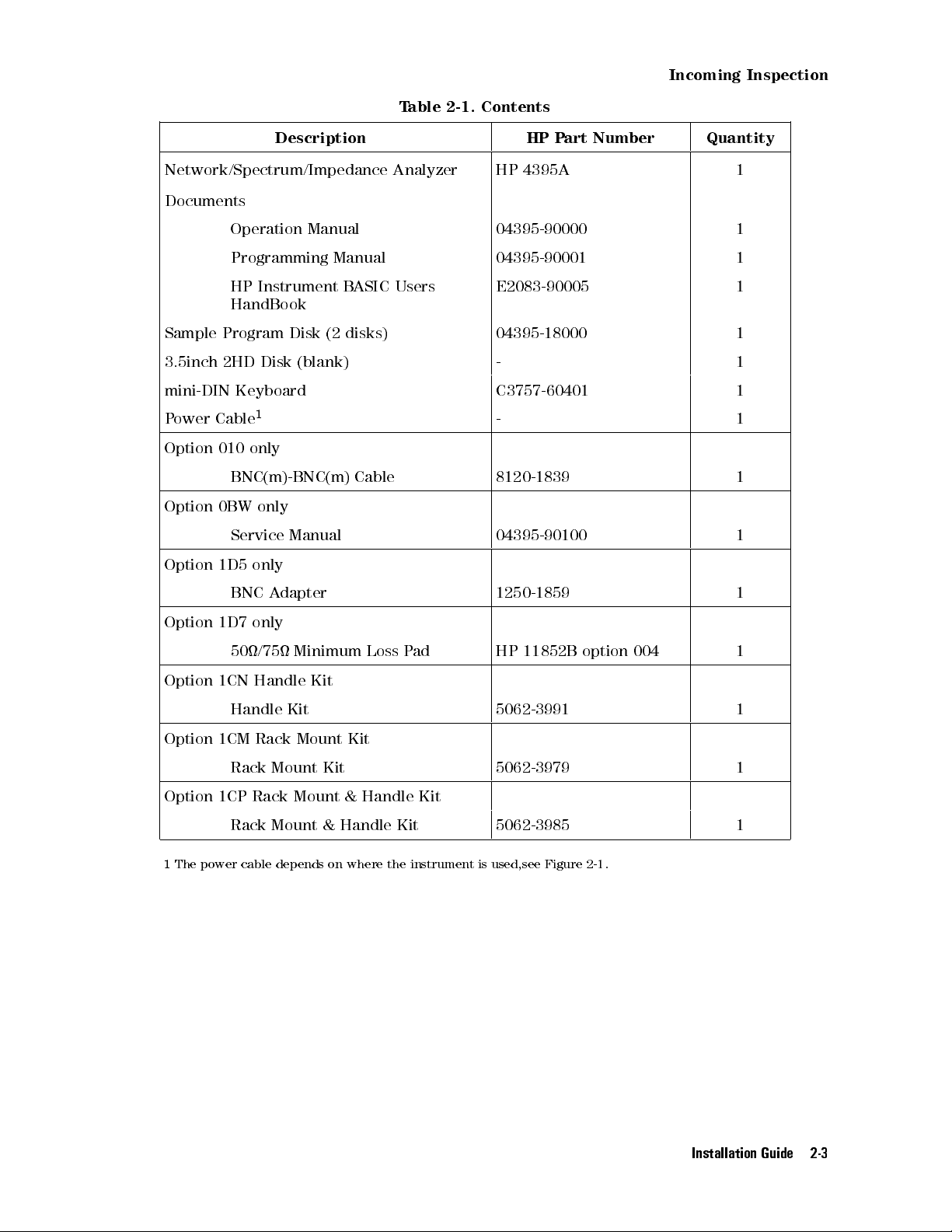
Incoming Inspection
Table 2-1. Contents
Description HP Part Number Quantity
Network/Spectrum/Impedance Analyzer HP 4395A 1
Documents
Operation Manual 04395-90000 1
Programming Manual 04395-90001 1
HP Instrument BASIC Users
E2083-90005 1
HandBook
Sample Program Disk (2 disks) 04395-18000 1
3.5inch 2HD Disk (blank) - 1
mini-DIN Keyboard C3757-60401 1
Power Cable
1
- 1
Option 010 only
BNC(m)-BNC(m) Cable 8120-1839 1
Option 0BW only
Service Manual 04395-90100 1
Option 1D5 only
BNC Adapter 1250-1859 1
Option 1D7 only
50/75 Minimum Loss Pad HP 11852B option 004 1
Option 1CN Handle Kit
Handle Kit 5062-3991 1
Option 1CM Rack Mount Kit
Rack Mount Kit 5062-3979 1
Option 1CP Rack Mount & Handle Kit
Rack Mount & Handle Kit 5062-3985 1
1
The power cable depends on where the instrument is used,see Figure 2-1.
Installation Guide 2-3

Replacing Fuse
Replacing Fuse
Fuse Selection
Select proper fuse according to the Table 2-2.
Table 2-2. Fuse Selection
Fuse Rating/Type Fuse Part Number
5A 250Vac
UL/CSA type 2110-0030
Time Delay
For ordering the fuse,contact your nearest Hewlett-Packard Sales and Service Oce.
Procedure
Lever a small minus screwdriver to
dismount the fuse holder above the AC
line receptacle on the rear panel.
Caution
2-4 Installation Guide
Use the proper fuse for the line voltage selected. Use only fuses with the
required current rating and of the specied type as replacements. DO NOT use
a mended fuse or short-circuit the fuse-holder in order to by-pass a blown fuse.
Find out what caused the fuse to blow!
To check or replace the fuse, pull the fuse
holder and remove the fuse.To reinstall
the fuse, insert a fuse with the proper
rating into the fuse holder.
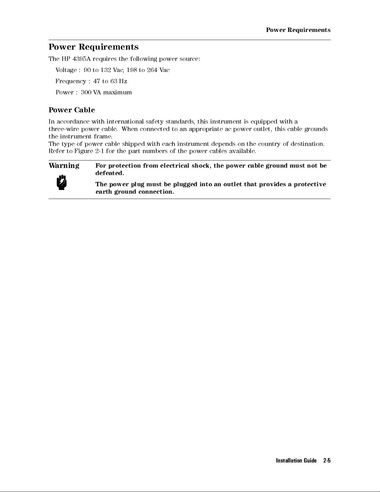
Power Requirements
Power Requirements
The HP 4395A requires the following power source:
Voltage : 90 to 132 Vac, 198 to 264 Vac
Frequency : 47 to 63 Hz
Power : 300 VA maximum
Power Cable
In accordance with international safety standards, this instrument is equipped with a
three-wire power cable. When connected to an appropriate ac power outlet, this cable grounds
the instrument frame.
The type of power cable shipped with each instrument depends on the country of destination.
Refer to Figure 2-1 for the part numbers of the power cables available.
Warning
For protection from electrical shock, the power cable ground must not be
defeated.
The power plug must be plugged into an outlet that provides a protective
earth ground connection.
Installation Guide 2-5

Power Requirements
2-6 Installation Guide
Figure 2-1. Power Cable Supplied
Operation Environment
Operation Environment
The HP 4395A must be operated under within the following environment conditions, and
sucient space must be kept behind the HP 4395A to avoid obstructing the air ow of the
cooling fans.
Temperature: 10Cto40C
Humidity: less than 80% RH
Note
Ventilation Requirements
To ensure adequate ventilation, make sure that there is adequate clearance of at least 180mm
behind and 60mm sides.
Instruction for Cleaning
To prevent electrical shock, disconnect the HP 4395A power cable from the receptacle before
cleaning. Wipe with a dry cloth or a soft cloth that is soaked with water and wrung tightly
without undue pressure to clean the casing. Do not attempt to clean the HP 4395A internally
The HP 4395A must be protected from temperature extremes which could
cause condensation within the instrument.
.
Installation Guide 2-7

Rack/Handle Installation
Rack/Handle Installation
The HP 4395A can be rack mounted and used as a component in a measurement system.
Figure 2-2 shows how to rack mount the HP 4395A.
Table 2-3. Rack Mount Kits
Option Description HP Part Number
1CN Handle Kit 5062-3991
1CM Rack Mount Kit 5062-3979
1CP Rack Mount & Handle Kit 5062-3985
Figure 2-2. Rack Mount Kits Installation
Option 1CN Handle Kit
Option 1CN is a handle kit containing a pair of handles and the necessary hardware to attach
them to the instrument.
Installing the Handle
1. Remove the adhesive-backed trim strips1
HP 4395A.
2. Attach the front handles3
3. Attach the trim strips4
2-8 Installation Guide
to the sides using the screws provided.
to the handles.
from the left and right front sides of the

Rack/Handle Installation
Option 1CM Rack Mount Kit
Option 1CM is a rack mount kit containing a pair of anges and the necessary hardware to
mount them to the instrument in an equipment rack with 482.6 mm (19 inches) horizontal
spacing.
Mounting the Rack
1. Remove the adhesive-backed trim strips1
from the left and right front sides of the
HP 4395A.
2. Attach the rack mount ange2
to the left and right front sides of the HP 4395A using the
screws provided.
3. Remove all four feet (lift bar on the inner side of the foot, and slide the foot toward the
bar).
Option 1CP Rack Mount & Handle Kit
Option 1CP is a rack mount kit containing a pair of anges and the necessary hardware to
mount them to an instrument which has handles attached, in an equipment rack with 482.6
mm (19 inches) spacing.
Mounting the Handle and Rack
1. Remove the adhesive-backed trim strips1
from the left and right front sides of the
HP 4395A.
2. Attach the front handle3
and the rack mount ange5
together on the left and right front
sides of the HP 4395A using the screws provided.
3. Remove all four feet (lift bar on the inner side of the foot, and slide the foot toward the
bar).
Connecting Cables
Use shielded cables when you connect the DUT and accessories for testing.
For more information about the cables, see chapter 12.
Installation Guide 2-9

Connecting a Test Set for Network Analyzer Mode
Connecting a Test Set for Network Analyzer Mode
To use the network analyzer mode of the HP 4395A, a test set is required to measure the
transmission and reection characteristics of the device under test (DUT).
You can use either the HP 87512A/B transmission/reection (T/R) test set or the HP 87511A/B
S-parameter test set. The HP 87512A/B T/R test set measures reection and transmission in the
forward direction only. The HP 87511A/B S-parameter test set measures both the forward and
reverse directions without reconnection.
For more information about the test sets, see Chapter 12.
Connecting a Transmission/Reection Test Set
Figure 2-3. Connecting a Transmission/Reection Test Set
1. Place the transmission/reection (T/R) test set in front of the HP 4395A.
2. Connect the R and A ports of the HP 4395A and the T/R test set to each other
.
3. Connect the RF OUT port of the HP 4395A and the RF IN port of the T/R test set with a
semi-rigid cable.
Note
When you use the HP 87512B, press
4
Cal
NNNNNNNNNNNNNN
5
MORE
NNNNNNNNNNNNNNNNNNNN
SET Z0
. Then press
4754554
to set the characteristic impedance (Z0)to75.
2-10 Installation Guide
5
2
1

Connecting an S-parameter Test Set
Connecting a Test Set for Network Analyzer Mode
Figure 2-4. Connecting an S-parameter Test Set
1. Place the HP 4395A on the S-parameter test set.
2. Connect the TEST SET-I/O INTERCONNECT interface on the rear panel of the HP 4395A
and the NETWORK ANALYZER-I/O INTERCONNECT interface of the test set using the cable
furnished with the test set.
3. Connect the RF OUT, R, A, and B inputs of the HP 4395A to the S-parameter test set to each
other.
N
NNNNNNNNNNNNN
Note
When you use the HP 87511B, press
to set the characteristic impedance (Z0)to75.
4
Cal
5
MORE
NNNNNNNNNNNNNNNNNNNN
SET Z0
. Then press
4754554
2
1
5
Installation Guide 2-11
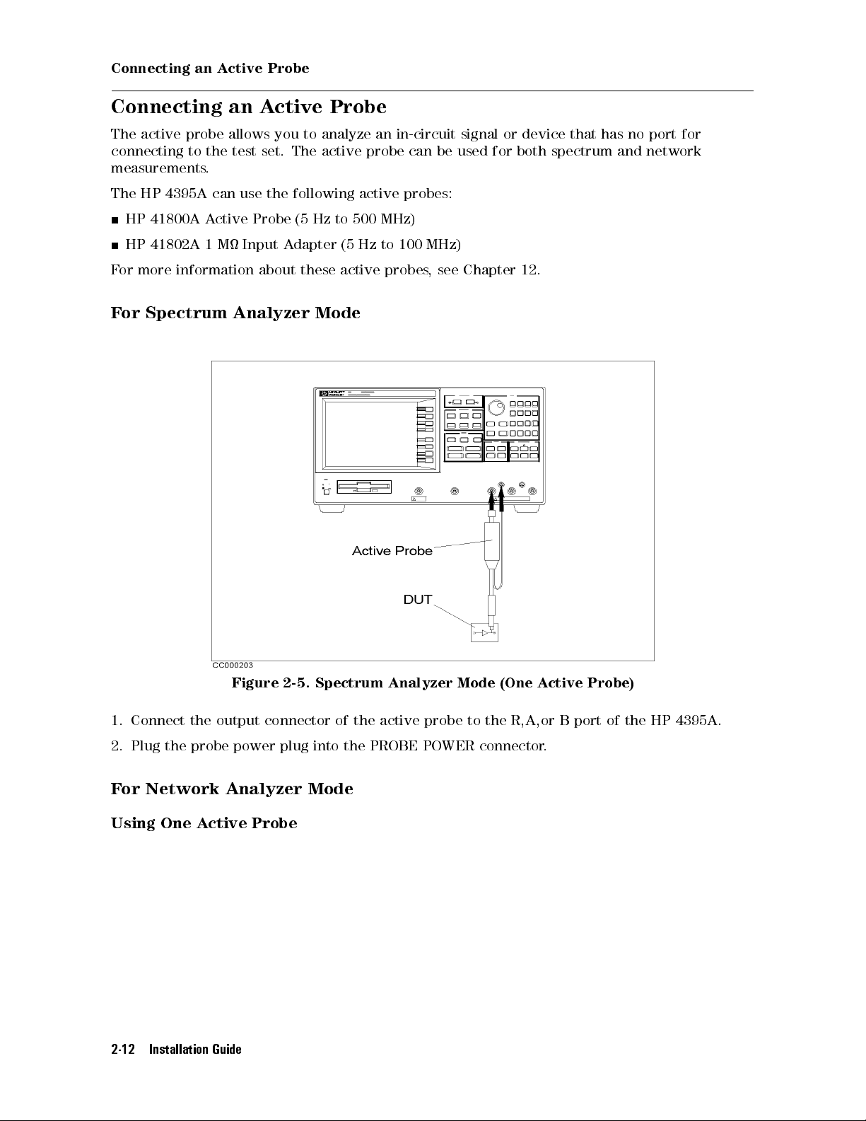
Connecting an Active Probe
Connecting an Active Probe
The active probe allows you to analyze an in-circuit signal or device that has no port for
connecting to the test set. The active probe can be used for both spectrum and network
measurements.
The HP 4395A can use the following active probes:
HP 41800A Active Probe (5 Hz to 500 MHz)
HP 41802A 1 M Input Adapter (5 Hz to 100 MHz)
For more information about these active probes, see Chapter 12.
For Spectrum Analyzer Mode
Figure 2-5. Spectrum Analyzer Mode (One Active Probe)
1. Connect the output connector of the active probe to the R,A,or B port of the HP 4395A.
2. Plug the probe power plug into the PROBE POWER connector.
For Network Analyzer Mode
Using One Active Probe
2-12 Installation Guide

Figure 2-6. Network Analyzer Mode (One Active Probe)
1. Connect the power splitter to the RF OUT port.
Connecting an Active Probe
2. Connect one output from the power splitter to the R input.
3. Connect the other output of the power splitter to the DUT
4. Connect the active probe to the B input and plug the probe plug into the PROBE POWER
connector.
5. If necessary, terminate the DUT with a load.
Note
For more information about these power splitters, see Chapter 12.
The following power splitters are available for the HP 4395A:
HP 11850C,D Three-way Power Splitter
HP 11667A Two-way Power Splitter
.
Installation Guide 2-13
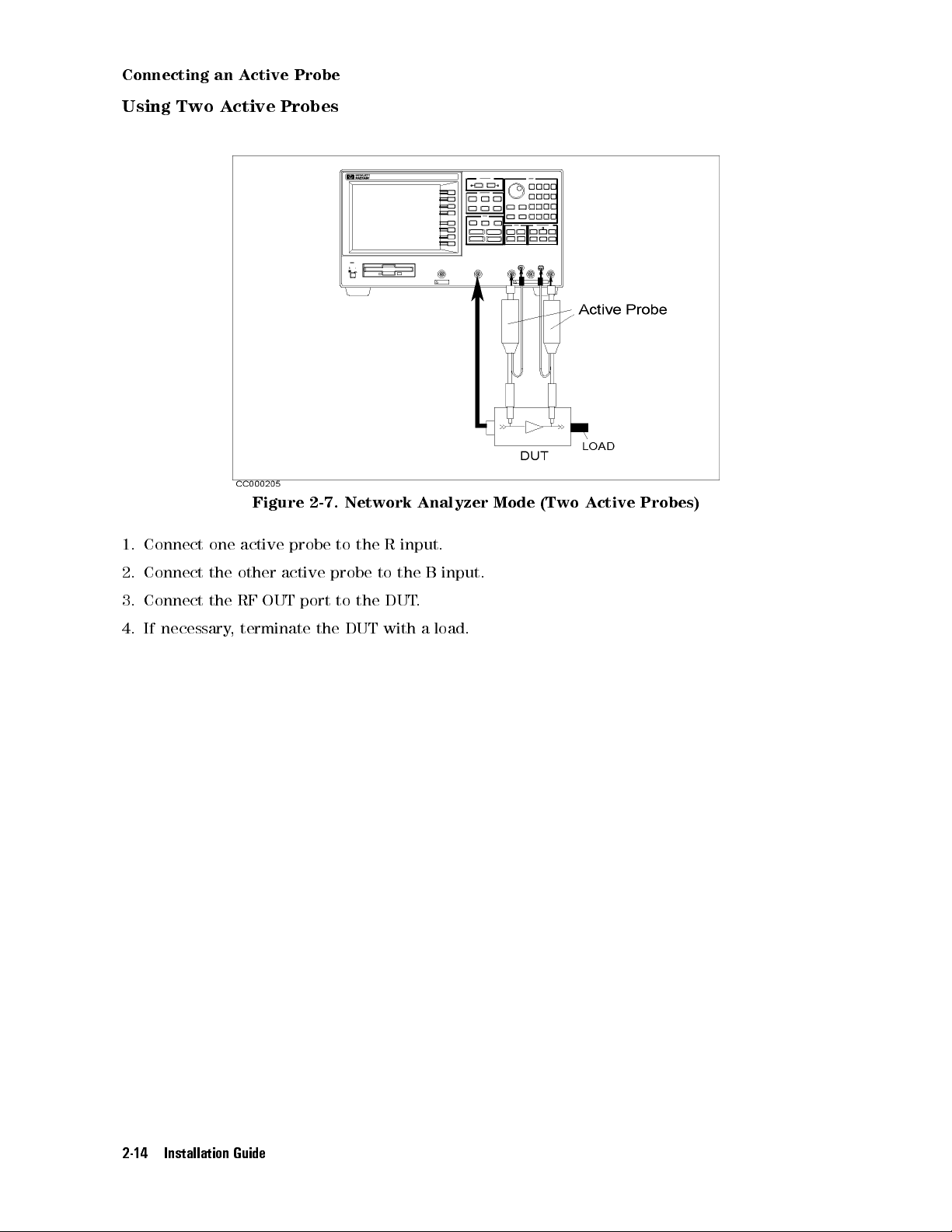
Connecting an Active Probe
Using Two Active Probes
Figure 2-7. Network Analyzer Mode (Two Active Probes)
1. Connect one active probe to the R input.
2. Connect the other active probe to the B input.
3. Connect the RF OUT port to the DUT
.
4. If necessary, terminate the DUT with a load.
2-14 Installation Guide

Using a Transmission/Reection Test Set
Figure 2-8. Using a Transmission/Reection Test Set
Connecting an Active Probe
1. Connect the HP 87512A/B T/R test set.
2. Connect the active probe to the B input.
3. If necessary, terminate the DUT with a load.
Installation Guide 2-15

Connecting an Active Probe
Connecting an Impedance Test Kit and a Test Fixture for Impedance
Analyzer Mode
Connecting an Impedance Test Kit
To start the impedance measurement, you need to connect the HP 43961A Impedance Test Kit
to the HP 4395A. See Figure 2-9.
1. Verify the HP 4395A is turned o.
2. Connect the N-cable to the RF OUT port of the HP 4395A.
3. Connect two connectors of the HP 43961A to the R and A ports of the HP 43961A.
4. Connect the other connector of the N-cable to the RF IN port of the HP 43961A.
5. Turn on the HP 4395A.
Figure 2-9. Connecting the Impedance Test Kit
Connecting a Test Fixture to the Impedance Test Kit
To connect the test xture to the impedance test kit, see the applicable test xture manual for
instructions. The following is a general procedure:
1. Turn the APC-7 connector of the impedance test kit OUTPUT port.
2. Verify that the connector sleeve is retracted fully.
3. Set the mounting posts of the test station into the twin locating holes at the corner of the
test xture.
4. Connect the connector on the underside of the test xture to the OUTPUT port of the
impedance test kit.
2-16 Installation Guide

Figure 2-10. Connecting Test Fixture
Connecting an Active Probe
Installation Guide 2-17

Connecting a Keyboard
Connecting a Keyboard
An mini-DIN keyboard can be connected to the mini-DIN connector on the rear panel of the
HP 4395A. The mini-DIN keyboard provides an easier way to enter characters for the le
names, display titles, and Instrument BASIC programs. It can also access the HP 4395A softkey
functions by using keyboard function keys.For more information on the mini-DIN keyboard,
see
Programming Manual
.
Figure 2-11. Connecting a Keyboard
2-18 Installation Guide
Setting Up a 75 Measurement For Spectrum Analyzer Mode
Setting Up a 75 Measurement For Spectrum Analyzer Mode
Note
This operation requires the option 1D7 50 to 75 Input Impedance
Conversion. For detail information about option 1D7, see Chapter 12.
1. Attach the HP 11852B Option 004 50 N(m)/75 N(f) minimum loss pad to R, A, or B input.
2. Press
3.
4. Press
Press
4
5
.
Cal
NNNNNNNNNNNNNNNNNNNNNN
N
INPUT Z
4*5
.
to set the impedance of the source (75 ). Then press
4
Entry O
5
.
5. Select the input port:
Attached to Press
NNNNNNNNNNNNNNNNNNNNNNNNNNNNNNNNNNNNNNNNNNNN
Input R
Input A
LVL CAL DATA R
NNNNNNNNNNNNNNNNNNNNNNNNNNNNNNNNNNNNNNNNNNNN
LVL CAL DATA A
NNNNNNNNNNNNNNNNNNNNNNNNNNNNNNNNNNNNNNNNNNNN
Input B
6. Enter the insertion loss of the minimum loss pad in dB and press
Note
Perform this procedure each time the HP 4395A is preset because the
HP 4395A does not retain this setting in memory
LVL CAL DATA B
4
5
.
2
1
.
Installation Guide 2-19

3
Quick Start Guide
Network Analyzer Tour
In this section, you explore the network analyzer mode of operation. Before starting this tour,
verify that the HP 4395A is correctly installed (see chapter 2, \Installation Guide," if you need
additional information).
Before You Leave On The Tour
On this tour, you will learn how to make a basic network analyzer measurement by measuring
the transmission characteristics of a bandpass lter.
Overview
The following is a short summary of the tour:
1. Preparing for a measurement
Turning ON the HP 4395A
Connecting the DUT
2. Setting up the HP 4395A
Selecting the analyzer type
Setting the active channel
Setting the input port
Setting the frequency range
Performing the automatic scaling
3. Making a calibration
4. Reading a measurement result
Reading a measured value by using marker
5. Printing out the measurement result
Conguring and connecting a printer
Making a hardcopy of the display
After you nish this tour, you will understand how to make a basic measurement in the
network analyzer mode of operation.
Quick Start Guide 3-1
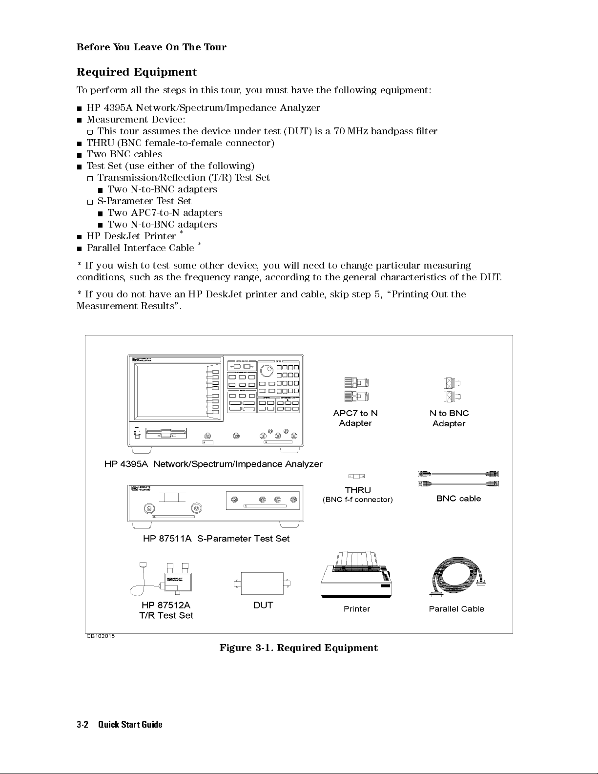
Before You Leave On The Tour
Required Equipment
To perform all the steps in this tour, you must have the following equipment:
HP 4395A Network/Spectrum/Impedance Analyzer
Measurement Device:
This tour assumes the device under test (DUT) is a 70 MHz bandpass lter
THRU (BNC female-to-female connector)
Two BNC cables
Test Set (use either of the following)
Transmission/Reection (T/R) Test Set
Two N-to-BNC adapters
S-Parameter Test Set
Two APC7-to-N adapters
Two N-to-BNC adapters
HP DeskJet Printer
Parallel Interface Cable
* If you wish to test some other device, you will need to change particular measuring
conditions, such as the frequency range, according to the general characteristics of the DUT.
*
*
* If you do not have an HP DeskJet printer and cable
Measurement Results".
, skip step 5, \Printing Out the
3-2 Quick Start Guide
Figure 3-1. Required Equipment

Step 1: Preparing for the Measurement
Step 1: Preparing for the Measurement
You must set up the test set before you turn ON the HP 4395A. The setup procedure for the
test set is described in \Connecting a Test Set for Network Analyzer Mode" in Chapter 2.
Turning ON the HP 4395A
Press the LINE switch.
The HP 4395A performs a power on self-test. About 20 seconds later
number, and other information should appear on the LCD to indicate that the HP 4395A has
normally started up.
Connecting the DUT
Connect the DUT as shown in Figure 3-2 or Figure 3-3.
, the model name, revision
Figure 3-2. Transmission/Reection Test Set Setup
Quick Start Guide 3-3

Step 1: Preparing for the Measurement
Figure 3-3. S-Parameter Test Set Setup
3-4 Quick Start Guide
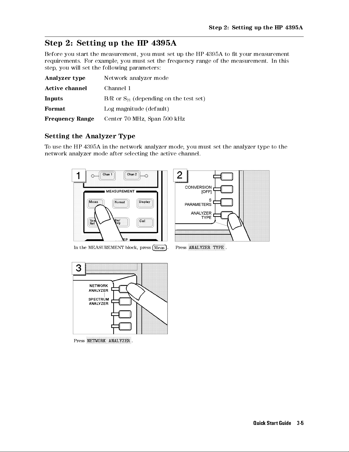
Step 2: Setting up the HP 4395A
Step 2: Setting up the HP 4395A
Before you start the measurement, you must set up the HP 4395A to t your measurement
requirements.For example, you must set the frequency range of the measurement. In this
step, you will set the following parameters:
Analyzer type
Active channel
Inputs
Format
Frequency Range
Network analyzer mode
Channel 1
B/R or S21(depending on the test set)
Log magnitude (default)
Center 70 MHz, Span 500 kHz
Setting the Analyzer Type
To use the HP 4395A in the network analyzer mode, you must set the analyzer type to the
network analyzer mode after selecting the active channel.
In the MEASUREMENT block, press
4
Meas
5
. Press
FFFFFFFFFFFFFFFFFFFFFFFFFFFFFFFFFF
ANALYZER TYPE
.
F
FFFFFFFFFFFFFFFFFFFFFFFFFFFFFFFFFFFFFFFF
Press
NETWORK ANALYZER
.
Quick Start Guide 3-5
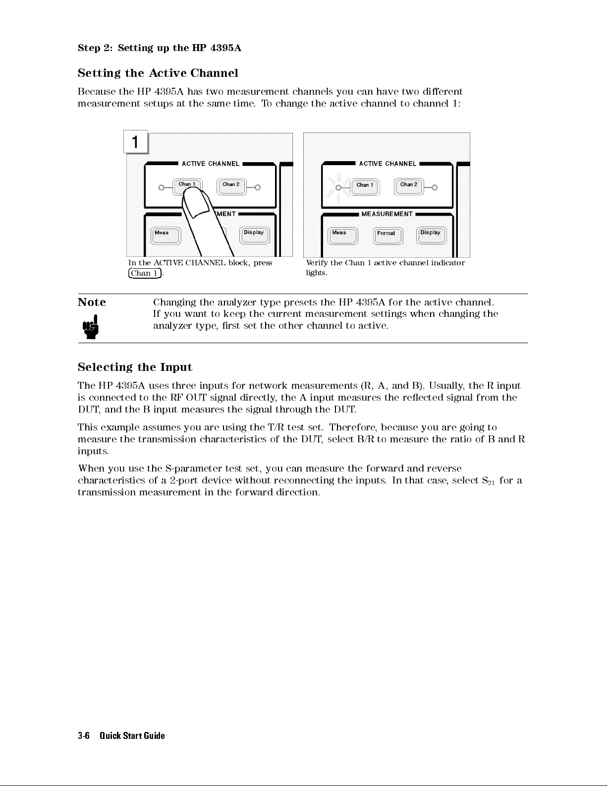
Step 2: Setting up the HP 4395A
Setting the Active Channel
Because the HP 4395A has two measurement channels you can have two dierent
measurement setups at the same time.To change the active channel to channel 1:
Note
In the ACTIVE CHANNEL block, press
4
5
Chan 1
.
Changing the analyzer type presets the HP 4395A for the active channel.
Verify the Chan 1 active channel indicator
lights.
If you want to keep the current measurement settings when changing the
analyzer type, rst set the other channel to active.
Selecting the Input
The HP 4395A uses three inputs for network measurements (R, A, and B). Usually
, the R input
is connected to the RF OUT signal directly, the A input measures the reected signal from the
DUT, and the B input measures the signal through the DUT
This example assumes you are using the T/R test set. Therefore
.
, because you are going to
measure the transmission characteristics of the DUT, select B/R to measure the ratio of B and R
inputs.
When you use the S-parameter test set, you can measure the forward and reverse
characteristics of a 2-port device without reconnecting the inputs
. In that case, select S
21
for a
transmission measurement in the forward direction.
3-6 Quick Start Guide
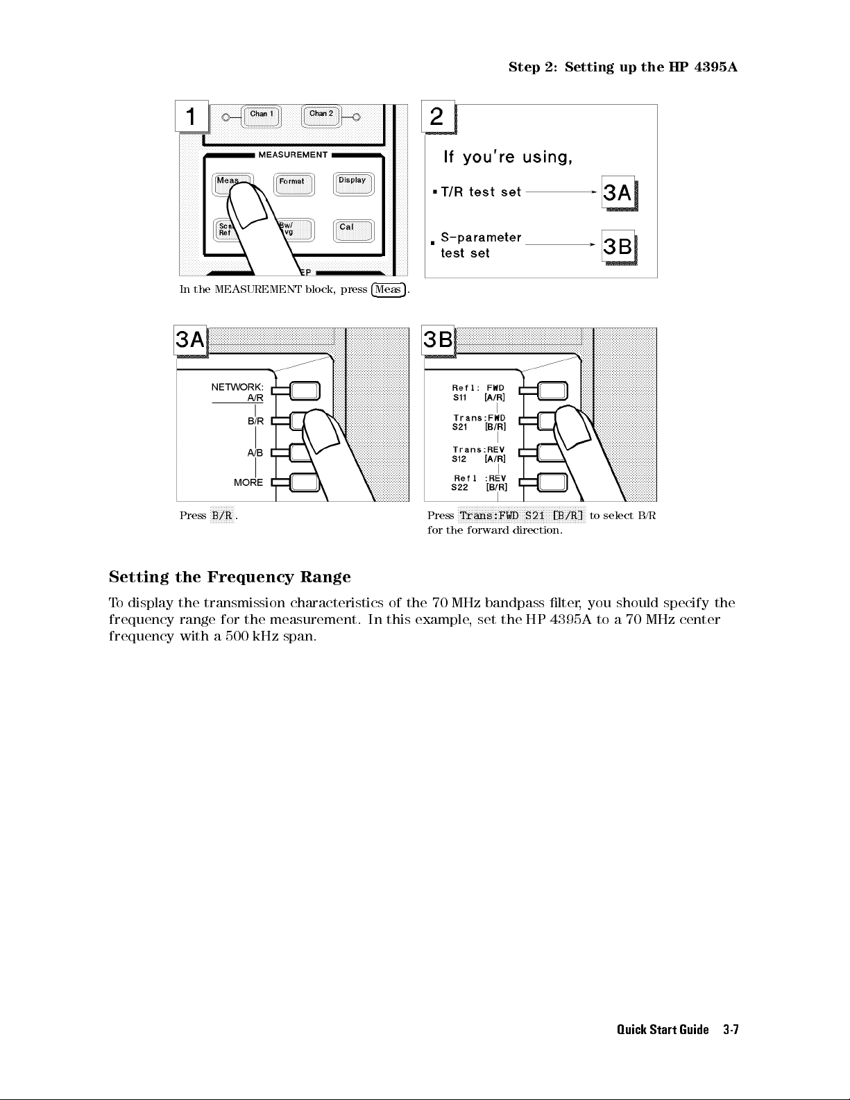
Step 2: Setting up the HP 4395A
In the MEASUREMENT block, press
F
FFFFFFFF
Press
B/R
. Press
Setting the Frequency Range
To display the transmission characteristics of the 70 MHz bandpass lter
frequency range for the measurement. In this example, set the HP 4395A to a 70 MHz center
frequency with a 500 kHz span.
4
Meas
5
.
F
FFFFFFFFFFFFFFFFFFFFFFFFFFFFFFFFFFFFFFFFFFFFFFF
Trans:FWD S21 [B/R]
for the forward direction.
to select B/R
, you should specify the
Quick Start Guide 3-7

Step 2: Setting up the HP 4395A
In the SWEEP block, press
Press
4
5
. In the SWEEP block, press
M/
4
Center
5
. Press
475405
.
4
5
.
Span
Press
455405405
Performing the Automatic Scaling
Often, the trace obtained after specifying the frequency range is too large or too small
vertically for the grid. However, by using the automatic scaling function, you can obtain the
optimum vertical setting automatically.
3-8 Quick Start Guide
. Press
4
k/m
5
.
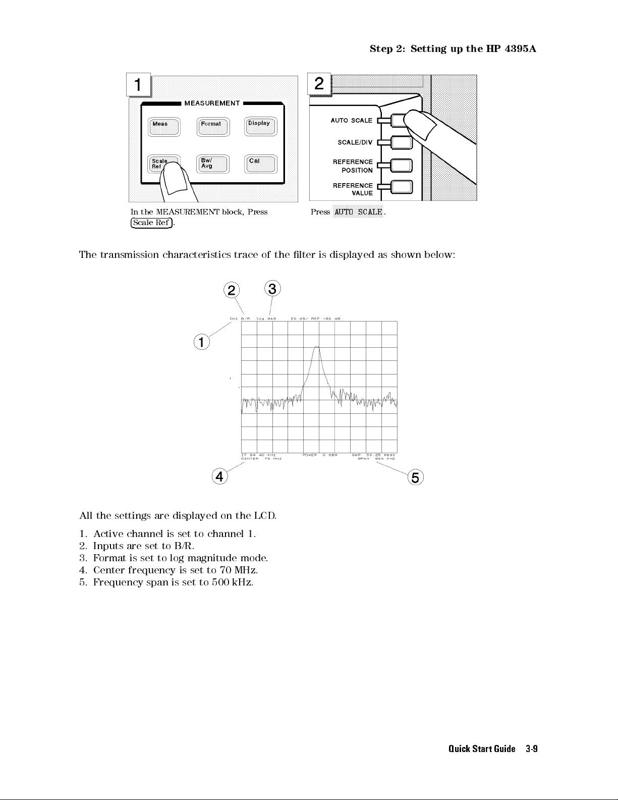
Step 2: Setting up the HP 4395A
In the MEASUREMENT block, Press
4
Scale Ref
The transmission characteristics trace of the lter is displayed as shown below:
5
.
Press
FFFFFFFFFFFFFFFFFFFFFFFFFF
AUTO SCALE
.
All the settings are displayed on the LCD.
1. Active channel is set to channel 1.
2. Inputs are set to B/R.
3. Format is set to log magnitude mode.
4. Center frequency is set to 70 MHz.
5. Frequency span is set to 500 kHz.
Quick Start Guide 3-9
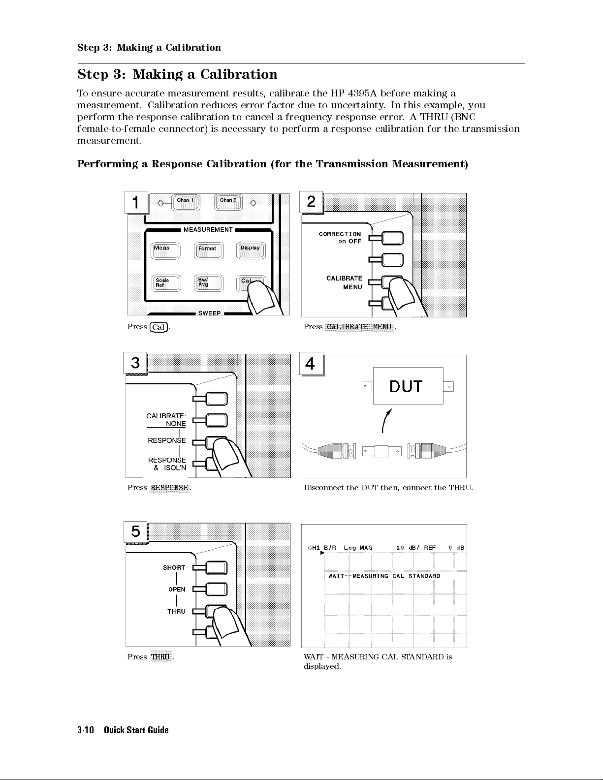
Step 3: Making a Calibration
Step 3: Making a Calibration
To ensure accurate measurement results, calibrate the HP 4395A before making a
measurement. Calibration reduces error factor due to uncertainty. In this example, you
perform the response calibration to cancel a frequency response error. A THRU (BNC
female-to-female connector) is necessary to perform a response calibration for the transmission
measurement.
Performing a Response Calibration (for the Transmission Measurement)
Press
Press
4
5
. Press
Cal
FFFFFFFFFFFFFFFFFFFFF
RESPONSE
. Disconnect the DUT then, connect the THRU.
FFFFFFFFFFFFFFFFFFFFFFFFFFFFFFFFFFFF
CALIBRATE MENU
.
F
FFFFFFFFFFF
THRU
Press
3-10 Quick Start Guide
. WAIT - MEASURING CAL STANDARD is
displayed.

Step 3: Making a Calibration
FFFFFFFFFFFF
The
THRU
softkey label is underlined when
the measurement is completed.
Disconnect the THRU and reconnect the DUT.
\
Cor
" is displayed on the left side of the display to show that the frequency response error is
corrected.
The measured value is now corrected for the frequency response error
Note
If the trace is changed, it requires an adjustment of the scale
automatic scaling again by pressing
FFFFFFFFFFFFFFFFFFFFFFFFFFFFFFFFFFFF
Press
DONE: RESPONSE
4
Scale Ref
.
NNNNNNNNNNNNNNNNNNNNNNNNNNNNNNN
N
5
AUTO SCALE
.
.Perform the
.
Quick Start Guide 3-11
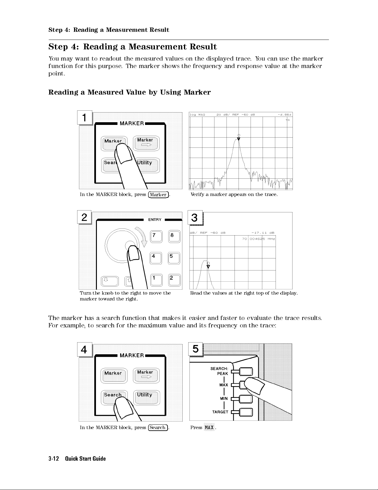
Step 4: Reading a Measurement Result
Step 4: Reading a Measurement Result
You may want to readout the measured values on the displayed trace.You can use the marker
function for this purpose. The marker shows the frequency and response value at the marker
point.
Reading a Measured Value by Using Marker
In the MARKER block, press
Turn the knob to the right to move the
marker toward the right.
The marker has a search function that makes it easier and faster to evaluate the trace results.
For example, to search for the maximum value and its frequency on the trace:
4
Marker
5
. Verify a marker appears on the trace.
Read the values at the right top of the display
.
In the MARKER block, press
3-12 Quick Start Guide
4
Search
5
. Press
F
FFFFFFFF
MAX
.
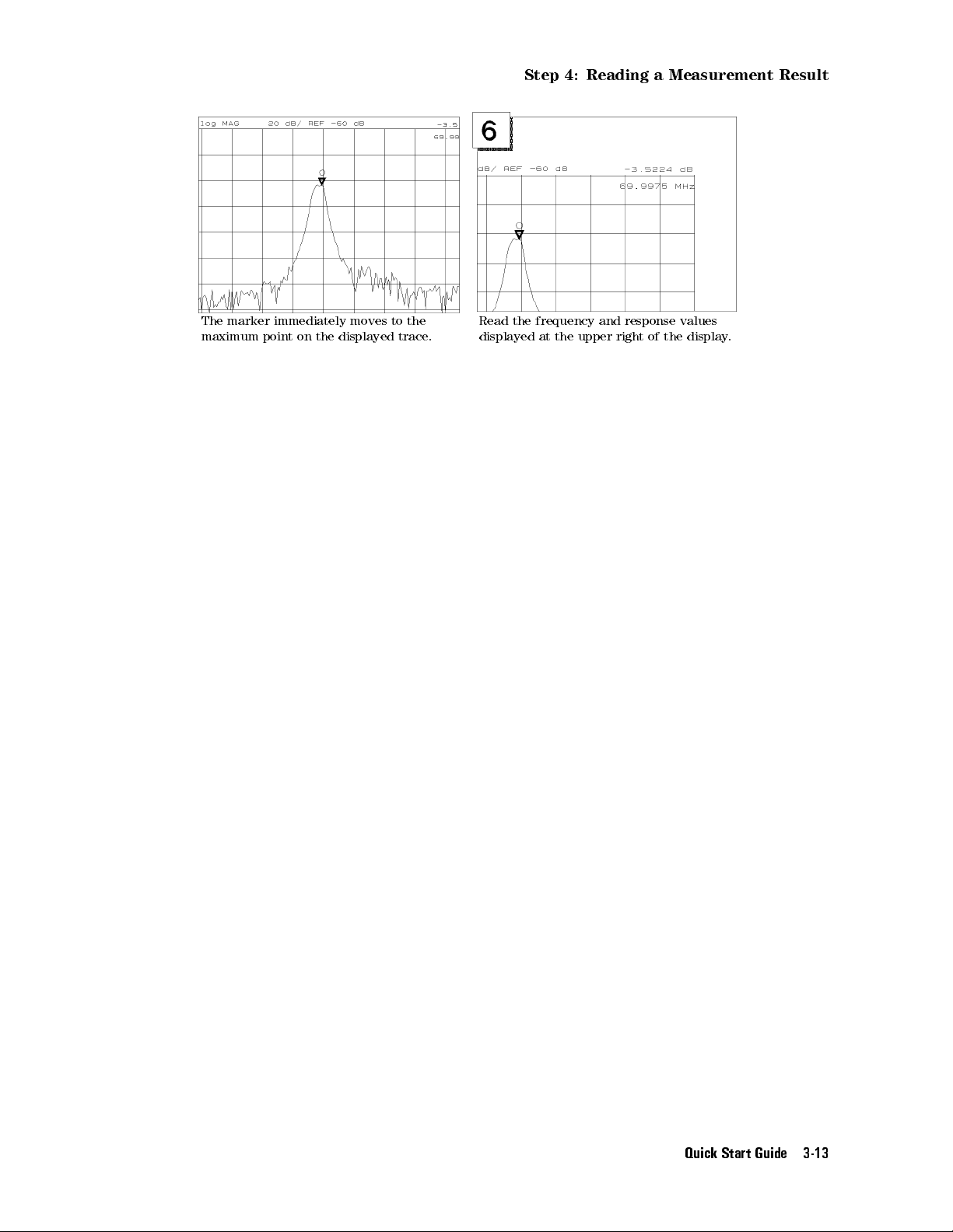
Step 4: Reading a Measurement Result
The marker immediately moves to the
maximum point on the displayed trace.
Read the frequency and response values
displayed at the upper right of the display.
Quick Start Guide 3-13
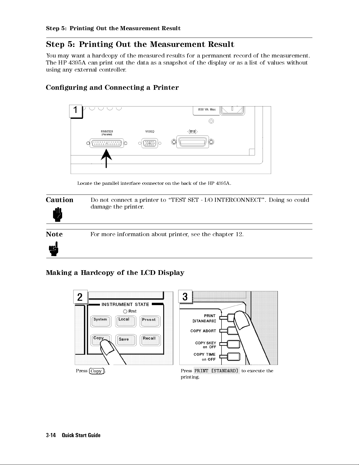
Step 5: Printing Out the Measurement Result
Step 5: Printing Out the Measurement Result
You may want a hardcopy of the measured results for a permanent record of the measurement.
The HP 4395A can print out the data as a snapshot of the display or as a list of values without
using any external controller.
Conguring and Connecting a Printer
Locate the parallel interface connector on the back of the HP 4395A .
Caution
Note
Making a Hardcopy of the LCD Display
Do not connect a printer to \TEST SET - I/O INTERCONNECT". Doing so could
damage the printer.
For more information about printer, see the chapter 12.
Press
4
5
. Press
Copy
F
FFFFFFFFFFFFFFFFFFFFFFFFFFFFFFFFFFFFFFFF
PRINT [STANDARD]
printing.
to execute the
3-14 Quick Start Guide
Spectrum Analyzer Tour
Spectrum Analyzer Tour
In this section, you explore the spectrum analyzer mode of operation. Before starting this tour,
verify the HP 4395A is correctly installed (see chapter 2, \Installation Guide," if you need
additional information).
Before You Leave On The Tour
On this tour, you will learn how to make a basic spectrum analyzer measurement by measuring
the output signal of a signal generator.
Overview
The following is a short summary of the tour:
1. Preparing for a measurement
Turning ON the HP 4395A
Connecting the test signal source
2. Setting up the HP 4395A
Selecting the analyzer type
Setting the active channel
Selecting the input
Setting the frequency range
3. Making a Measurement
Reading the peak level using the marker
Setting the resolution bandwidth to see low level signals
Searching for harmonics using the search function
4. Saving and recalling the HP 4395A settings
Preparing the disk
Saving HP 4395A settings
Entering the le name
Recalling the HP 4395A settings
After you nish this tour, you will understand how to make a basic measurement in the
spectrum analyzer mode of operation.
Quick Start Guide 3-15
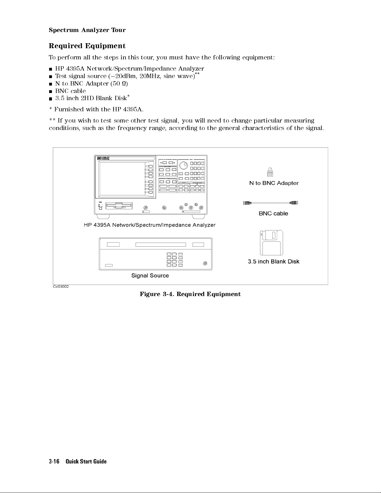
Spectrum Analyzer Tour
Required Equipment
To perform all the steps in this tour, you must have the following equipment:
HP 4395A Network/Spectrum/Impedance Analyzer
Test signal source (020dBm, 20MHz, sine wave)
N to BNC Adapter (50 )
BNC cable
3.5 inch 2HD Blank Disk
* Furnished with the HP 4395A.
** If you wish to test some other test signal, you will need to change particular measuring
conditions, such as the frequency range, according to the general characteristics of the signal.
*
**
3-16 Quick Start Guide
Figure 3-4. Required Equipment
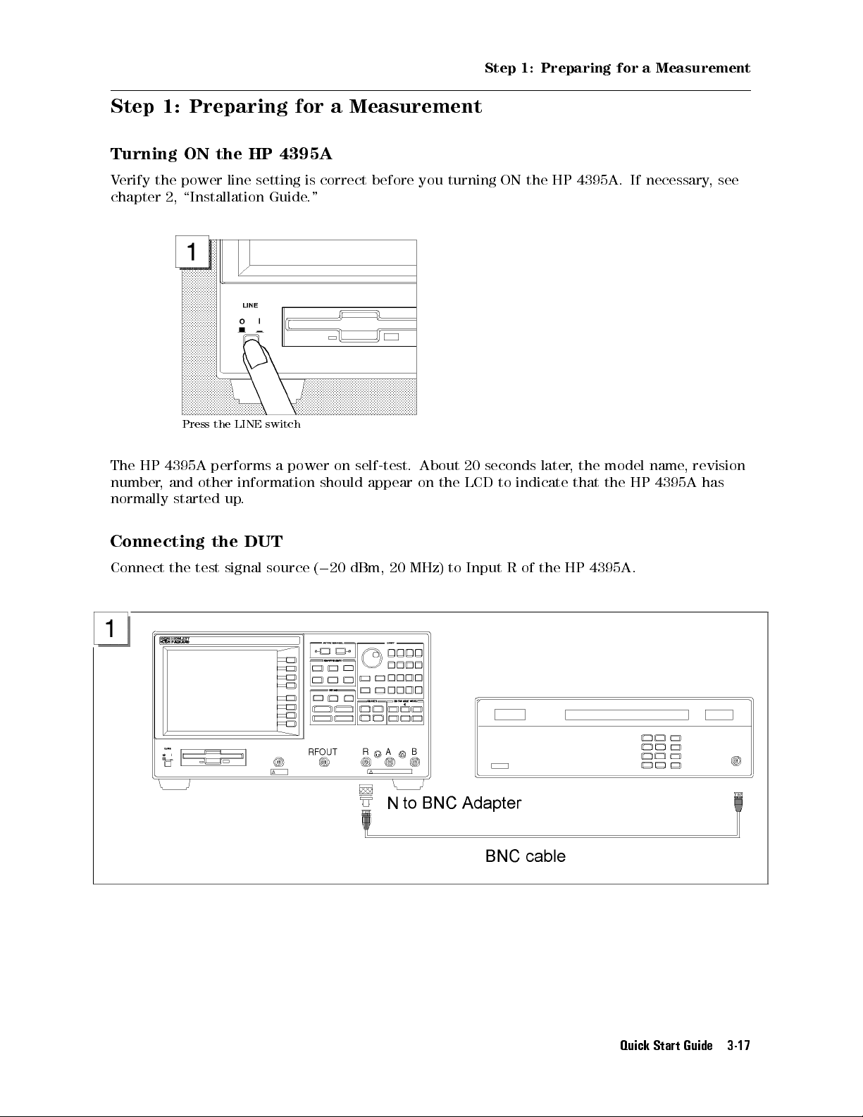
Step 1: Preparing for a Measurement
Step 1: Preparing for a Measurement
Turning ON the HP 4395A
Verify the power line setting is correct before you turning ON the HP 4395A. If necessary, see
chapter 2, \Installation Guide."
Press the LINE switch
The HP 4395A performs a power on self-test. About 20 seconds later
number, and other information should appear on the LCD to indicate that the HP 4395A has
normally started up.
Connecting the DUT
Connect the test signal source (020 dBm, 20 MHz) to Input R of the HP 4395A.
, the model name, revision
Quick Start Guide 3-17
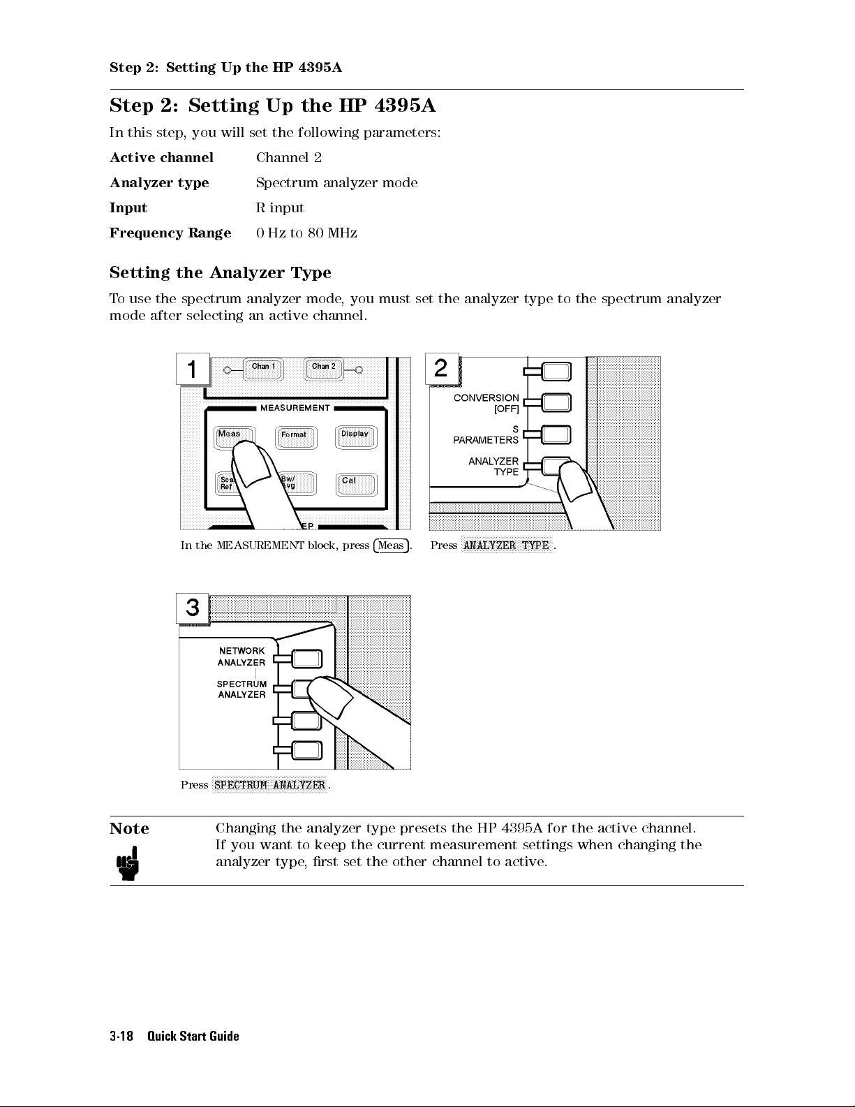
Step 2: Setting Up the HP 4395A
Step 2: Setting Up the HP 4395A
In this step, you will set the following parameters:
Active channel
Analyzer type
Input
Frequency Range
Channel 2
Spectrum analyzer mode
R input
0 Hz to 80 MHz
Setting the Analyzer Type
To use the spectrum analyzer mode, you must set the analyzer type to the spectrum analyzer
mode after selecting an active channel.
F
In the MEASUREMENT block, press
4
Meas
5
. Press
FFFFFFFFFFFFFFFFFFFFFFFFFFFFFFFFF
ANALYZER TYPE
.
FFFFFFFFFFFFFFFFFFFFFFFFFFFFFFFFFFFFFFFFFFF
Press
SPECTRUM ANALYZER
Note
Changing the analyzer type presets the HP 4395A for the active channel.
If you want to keep the current measurement settings when changing the
analyzer type, rst set the other channel to active.
3-18 Quick Start Guide
.
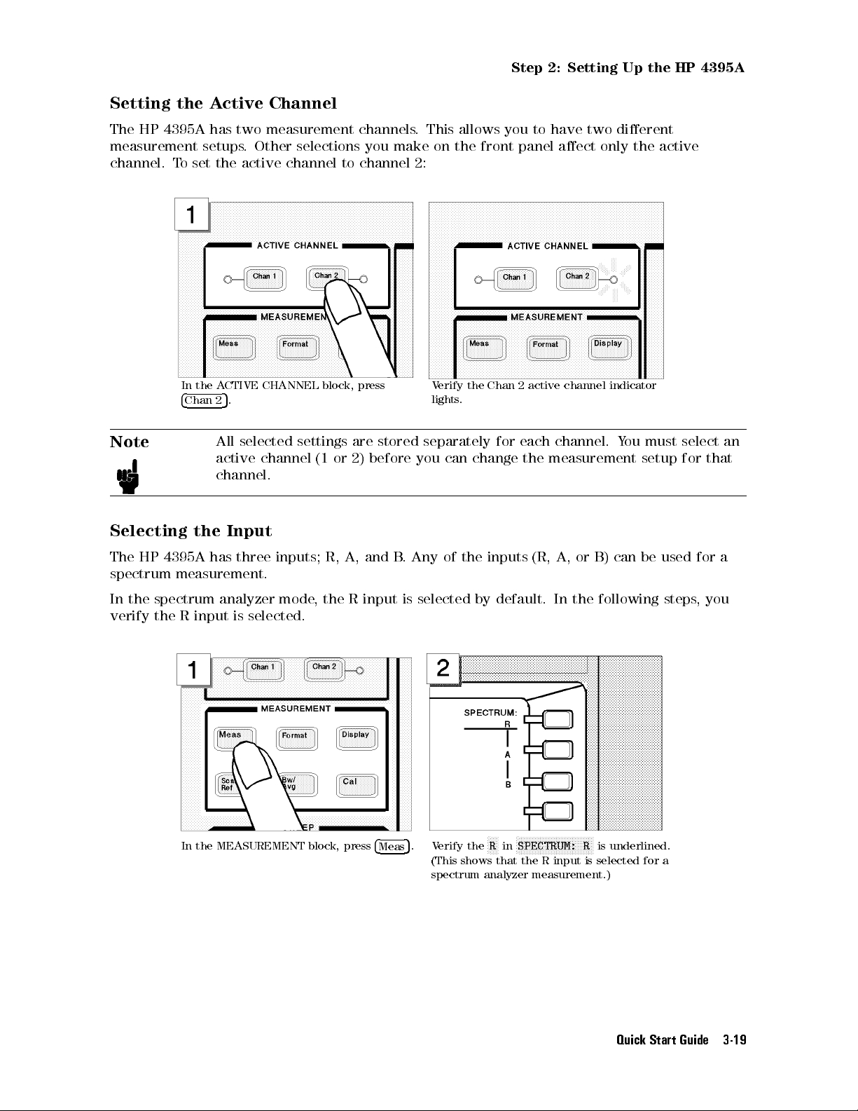
Step 2: Setting Up the HP 4395A
Setting the Active Channel
The HP 4395A has two measurement channels. This allows you to have two dierent
measurement setups. Other selections you make on the front panel aect only the active
channel. To set the active channel to channel 2:
Note
In the ACTIVE CHANNEL block, press
4
5
Chan 2
.
All selected settings are stored separately for each channel. Y
Verify the Chan 2 active channel indicator
lights.
ou must select an
active channel (1 or 2) before you can change the measurement setup for that
channel.
Selecting the Input
The HP 4395A has three inputs; R, A, and B
. Any of the inputs (R, A, or B) can be used for a
spectrum measurement.
In the spectrum analyzer mode, the R input is selected by default. In the following steps
verify the R input is selected.
, you
In the MEASUREMENT block, press
4
Meas
F
F
FFF
5
. Verify the
FFFFFFFFFFFFFFFFFFFFFFFFFFFF
R
in
SPECTRUM: R
is underlined.
(This shows that the R input is selected for a
spectrum analyzer measurement.)
Quick Start Guide 3-19

Step 2: Setting Up the HP 4395A
Setting the Frequency Range
The CAL OUT signal (20 MHz at020 dBm) is connected as test signal source.To see this signal
on display, you must set the appropriate frequency range (in this case, 0 to 80 MHz):
In the SWEEP block, press
Press
4
5
. Press
2
1
4
5
. Press
Start
405
4
Stop
.
5
.
Press
4
5
. Press
8540
Verify the 20 MHz signal is displayed as shown below:
3-20 Quick Start Guide
4
5
.
M/
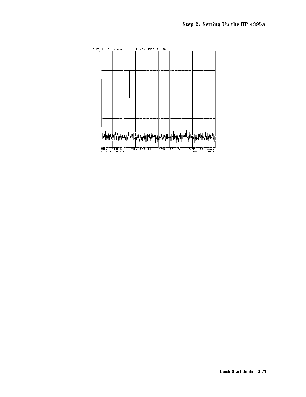
Step 2: Setting Up the HP 4395A
Quick Start Guide 3-21
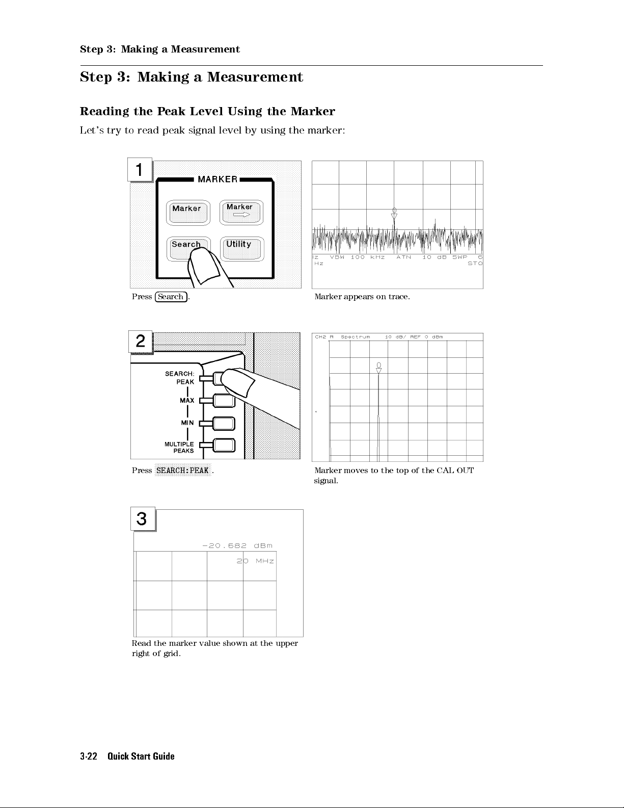
Step 3: Making a Measurement
Step 3: Making a Measurement
Reading the Peak Level Using the Marker
Let's try to read peak signal level by using the marker:
Press
4
5
. Marker appears on trace.
Search
FFFFFFFFFFFFFFFFFFFFFFFFFFFFF
Press
SEARCH:PEAK
Read the marker value shown at the upper
right of grid.
3-22 Quick Start Guide
. Marker moves to the top of the CAL OUT
signal.
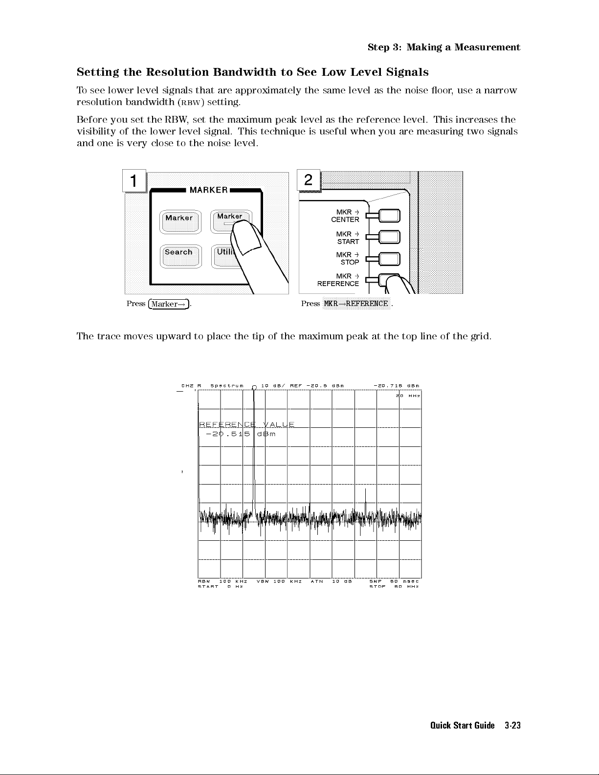
Step 3: Making a Measurement
Setting the Resolution Bandwidth to See Low Level Signals
To see lower level signals that are approximately the same level as the noise oor, use a narrow
resolution bandwidth (
Before you set the RBW, set the maximum peak level as the reference level. This increases the
visibility of the lower level signal. This technique is useful when you are measuring two signals
and one is very close to the noise level.
Press
4
Marker
rbw
) setting.
5
. Press
!
F
FFFFFFFFFFFFFFFFFFFFFFFFFFFFFFFFFFF
MKR!REFERENCE
.
The trace moves upward to place the tip of the maximum peak at the top line of the grid.
Quick Start Guide 3-23
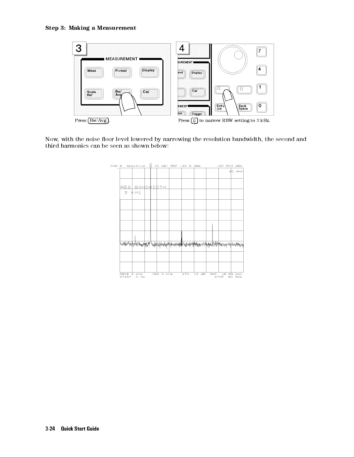
Step 3: Making a Measurement
Press
4
Bw/Avg
5
. Press
4+5
to narrow RBW setting to 3 kHz.
Now, with the noise oor level lowered by narrowing the resolution bandwidth, the second and
third harmonics can be seen as shown below:
3-24 Quick Start Guide

Step 3: Making a Measurement
Searching for Harmonics Using the Search Function
You can easily readout a harmonics' frequency and level by using the peak search function:
F
Press
4
Search
5
. Press
FFFFFFFFFFFFFFFFFFFFFFFFFFFF
SEARCH:PEAK
.
FFFFFFFFFFFFFFFFFFFFFFFF
Press
NEXT PEAK
To move the marker to the second (or third)
harmonic, press
. The marker moves to the third (or second)
FFFFFFFFFFFFFFFFFFFFFFFF
NEXT PEAK
again.
harmonic.
Quick Start Guide 3-25
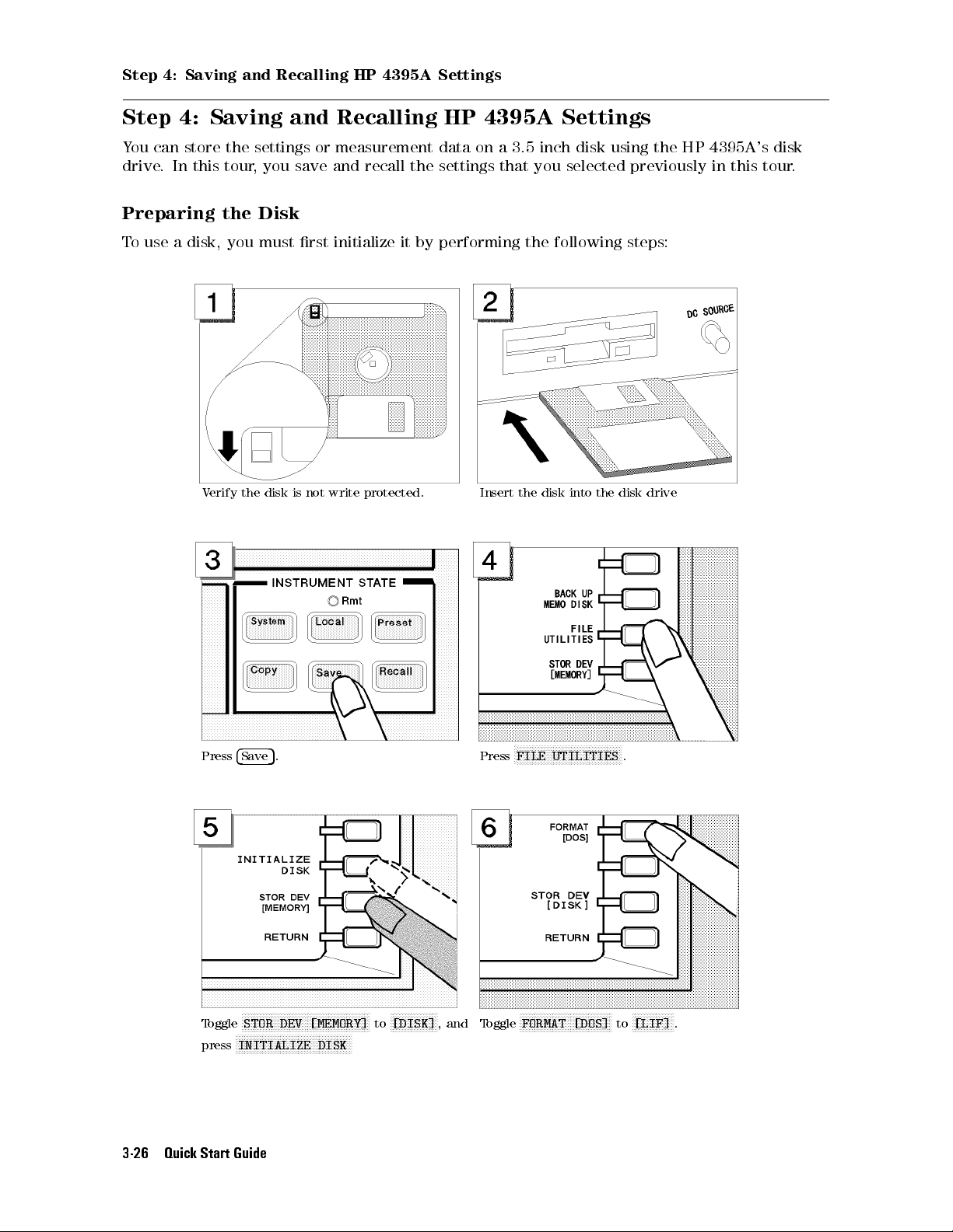
Step 4: Saving and Recalling HP 4395A Settings
Step 4: Saving and Recalling HP 4395A Settings
You can store the settings or measurement data on a 3.5 inch disk using the HP 4395A's disk
drive. In this tour, you save and recall the settings that you selected previously in this tour.
Preparing the Disk
To use a disk, you must rst initialize it by performing the following steps:
Verify the disk is not write protected. Insert the disk into the disk drive
Press
4
Save
F
FFFFFFFFFFFFFFFFFFFFFFFFFFFFFFFFFFFFFFFFFF
Toggle
STOR DEV [MEMORY]
F
FFFFFFFFFFFFFFFFFFFFFFFFFFFFFFFFFFFFFF
INITIALIZE DISK
press
3-26 Quick Start Guide
5
. Press
F
FFFFFFFFFFFFFFF
to
[DISK]
, and
Toggle
F
FFFFFFFFFFFFFFFFFFFFFFFFFFFFFFFFFFF
FILE UTILITIES
F
FFFFFFFFFFFFFFFFFFFFFFFFFFFFFF
FORMAT [DOS]
.
to
F
FFFFFFFFFFFFF
[LIF]
.
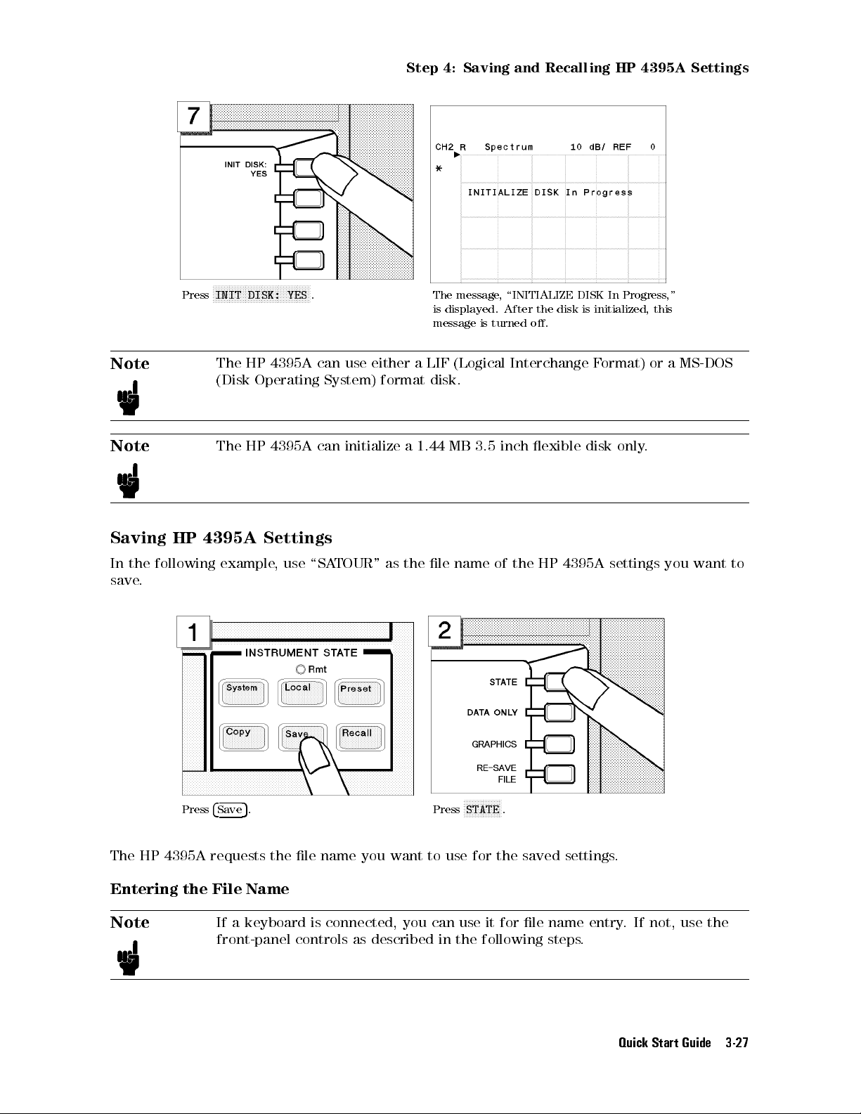
FFFFFFFFFFFFFFFFFFFFFFFFFFFFFFFFFFFF
Press
INIT DISK: YES
Step 4: Saving and Recalling HP 4395A Settings
. The message, \INITIALIZE DISK In Progress,"
is displayed. After the disk is initialized, this
message is turned o.
Note
The HP 4395A can use either a LIF (Logical Interchange Format) or a MS-DOS
(Disk Operating System) format disk.
Note
The HP 4395A can initialize a 1.44 MB 3.5 inch exible disk only
.
Saving HP 4395A Settings
In the following example, use \SATOUR" as the le name of the HP 4395A settings you want to
save.
Press
4
5
. Press
Save
FFFFFFFFFFFFFF
STATE
.
The HP 4395A requests the le name you want to use for the saved settings.
Entering the File Name
Note
If a keyboard is connected, you can use it for le name entry. If not, use the
front-panel controls as described in the following steps
.
Quick Start Guide 3-27

Step 4: Saving and Recalling HP 4395A Settings
Turn the rotary knob to move the arrow
below the rst character,S.
Keep entering characters until SATOUR is
entered.
FFFFFFFFFFFFFFFFFFFFFFFFFFFFFFFFFF
Press
SELECT LETTER
If you enter a wrong character, press
FFFFFFFFFFFFFFFFFFFFFFFFFF
BACK SPACE
to erase the character.
.
To complete the le name entry, press
Note
3-28 Quick Start Guide
The le name for a LIF format can be up to 10 characters long. However, with
the HP 4395A, the last 2 characters are reserved for a sux. Therefore, you
can enter a le name of up to 8 characters. Either upper or lower case is
recognized in the LIF format.
A le name for a MS-DOS(DOS) format consists of a le name and an extension.
The le name can be up to 8 characters long and the extension contains up to 3
characters. A period separates the extension from the le name
FFFFFFFFFFFF
DONE
.Verify the disk access indicator lights (this
shows that the HP 4395A is saving the
settings to the disk).
. The extension

Step 4: Saving and Recalling HP 4395A Settings
part reserved by the HP 4395A. Therefore, you can enter a le name of up to 8
characters. The le name is not case sensitive in the DOS format.
Recalling the HP 4395A Settings
You can recall the le containing the saved HP 4395A settings anytime you want. This is
true, even if you change the current HP 4395A settings. In this example, you will preset the
HP 4395A and then recall the settings in the SATOUR le.
Presetting
Press
4
5
.
Preset
The HP 4395A is set to the preset conditions
previous examples are stored in the SATOUR le on the disk.
. However, the HP 4395A settings from the
Quick Start Guide 3-29
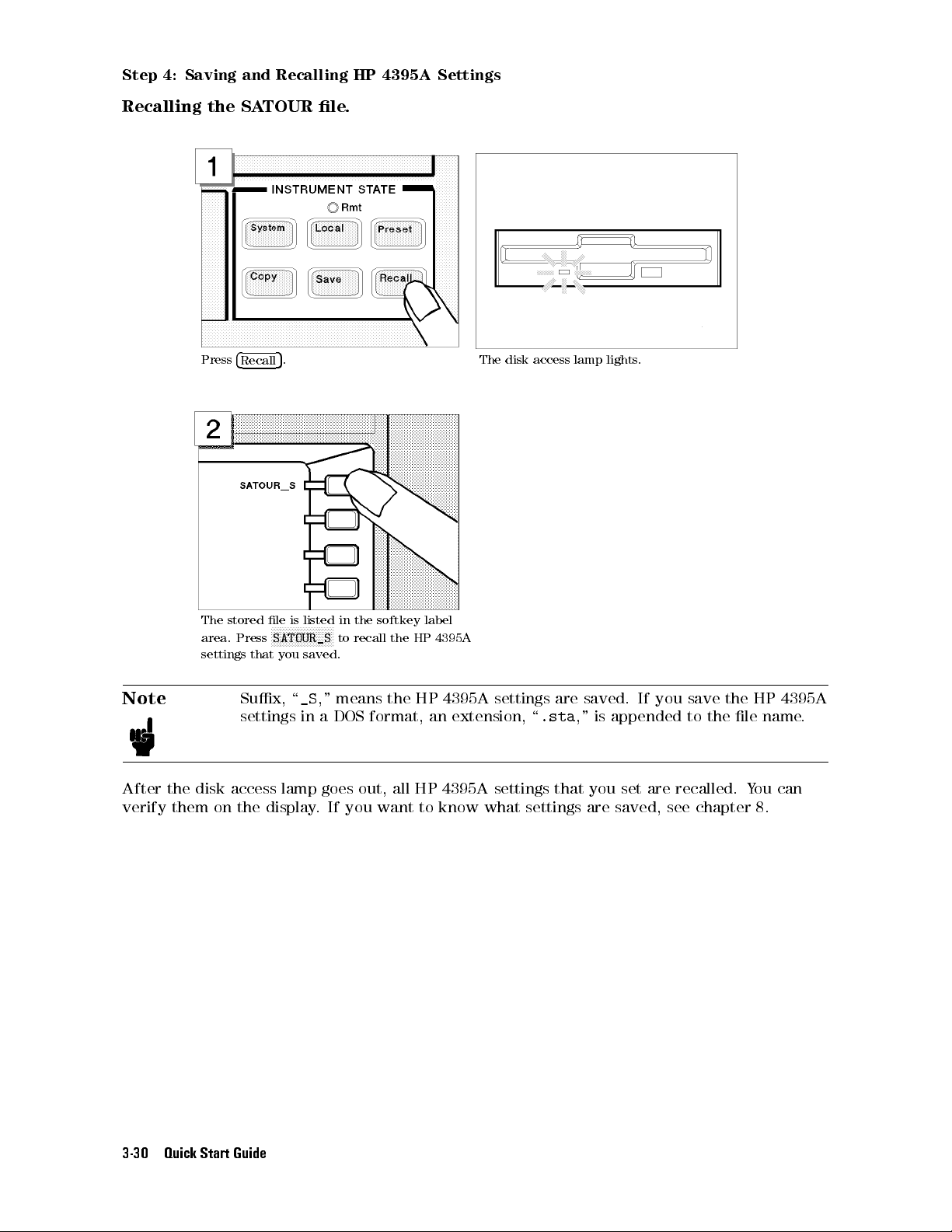
Step 4: Saving and Recalling HP 4395A Settings
Recalling the SATOUR le.
Press
4
5
. The disk access lamp lights.
Recall
The stored le is listed in the softkey label
area. Press
settings that you saved.
Note
After the disk access lamp goes out, all HP 4395A settings that you set are recalled. You can
verify them on the display. If you want to know what settings are saved, see chapter 8.
FFFFFFFFFFFFFFFFFFFFF
SATOUR_S
Sux, \_S," means the HP 4395A settings are saved. If you save the HP 4395A
settings in a DOS format, an extension, \
to recall the HP 4395A
.sta
," is appended to the le name.
3-30 Quick Start Guide

Impedance Analyzer Tour
Impedance Analyzer Tour
In this section, you explore the impedance analyzer mode of operation. Before starting this
tour, make sure that your HP 4395A is correctly installed (see chapter 1, \Installation and
Setup Guide," if you need additional information).
Note
Your HP 4395A must be equipped with option 010 to serve as an impedance
analyzer. Otherwise, impedance analyzer mode is not available.
Before You Leave On The Tour
Through this tour, you will learn how to make a basic impedance analyzer measurement by
measuring the impedance characteristics of a chip capacitor.
Overview
The following is a short summary of the tour:
1. Preparing for a measurement
Connecting the impedance test kit
Turning ON the HP 4395A
2. Setting up the HP 4395A
Selecting the analyzer type
Activating Channel 1
Setting the sweep parameters
Setting the output level
Setting the IF bandwidth
3. Calibrating the HP 4395A
OPEN calibration
SHORT calibration
LOAD calibration
4. Connecting and setting up a test xture
Connecting the xture
Setting the electrical length
Fixture compensation
5. Carrying out impedance measurement
Selecting the measurement parameters for Channel 1
Connecting the DUT
Performing the Automatic Scaling
6. Switching from Channel 1 to Channel 2
7. Selecting the measurement parameters for Channel 2
8. Dual channel display
Quick Start Guide 3-31

Impedance Analyzer Tour
After you nish this tour, you will understand how to make a basic measurement in impedance
analyzer mode. If you want to learn how to perform more complex tasks, refer to Chapters 5
through 9.
Required Equipment
To perform all the steps in this tour, you must have the following equipment:
Figure 3-5. Required Equipment
1. HP 4395A Network/Spectrum/Impedance Analyzer with Option 010 equipped
2. HP 43961A Impedance Test Kit
3. Calibration kit (included in the HP 43961A)
4. Test xture of your choice
5. Short device for the test xture
6. DUT (chip capacitor)
If you wish to test some other device instead of a chip capacitor
particular measuring conditions, such as the frequency range, according to the general
characteristics of the DUT.
*
, you will need to change
3-32 Quick Start Guide
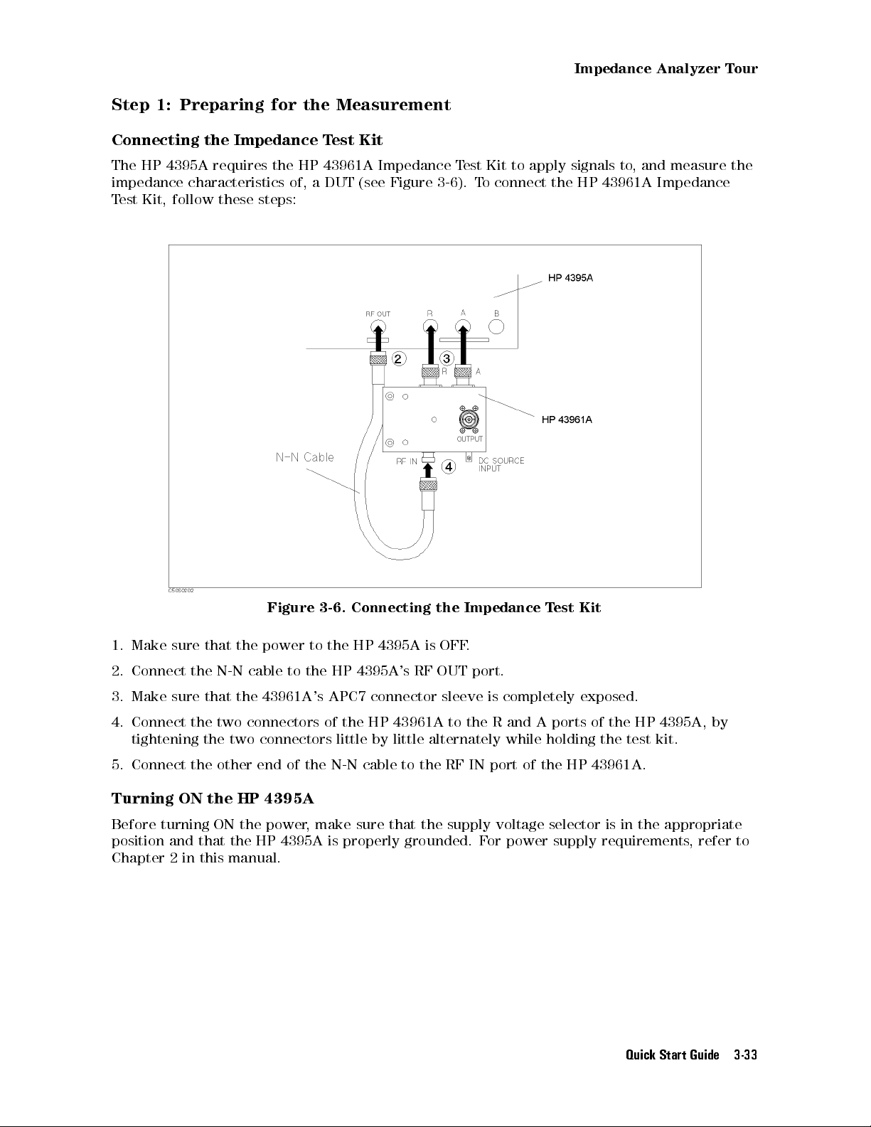
Impedance Analyzer Tour
Step 1: Preparing for the Measurement
Connecting the Impedance Test Kit
The HP 4395A requires the HP 43961A Impedance Test Kit to apply signals to, and measure the
impedance characteristics of, a DUT (see Figure 3-6). To connect the HP 43961A Impedance
Test Kit, follow these steps:
Figure 3-6. Connecting the Impedance Test Kit
1. Make sure that the power to the HP 4395A is OFF
2. Connect the N-N cable to the HP 4395A
3. Make sure that the 43961A's APC7 connector sleeve is completely exposed.
4. Connect the two connectors of the HP 43961A to the R and A ports of the HP 4395A, by
tightening the two connectors little by little alternately while holding the test kit.
5. Connect the other end of the N-N cable to the RF IN port of the HP 43961A.
Turning ON the HP 4395A
Before turning ON the power, make sure that the supply voltage selector is in the appropriate
position and that the HP 4395A is properly grounded. For power supply requirements, refer to
Chapter 2 in this manual.
's RF OUT port.
.
Quick Start Guide 3-33
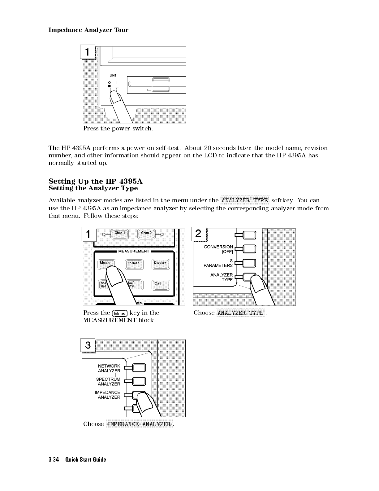
Impedance Analyzer Tour
Press the power switch.
The HP 4395A performs a power on self-test. About 20 seconds later, the model name, revision
number, and other information should appear on the LCD to indicate that the HP 4395A has
normally started up.
Setting Up the HP 4395A
Setting the Analyzer Type
Available analyzer modes are listed in the menu under the
use the HP 4395A as an impedance analyzer by selecting the corresponding analyzer mode from
that menu. Follow these steps:
NNNNNNNNNNNNNNNNNNNNNNNNNNNNNNNNNNNNNNNNN
ANALYZER TYPE
softkey.You can
Press the
MEASRUREMENT block.
Choose
3-34 Quick Start Guide
4
5
key in the
Meas
NNNNNNNNNNNNNNNNNNNNNNNNNNNNNNNNNNNNNNNNNNNNNNNNNNNNNNNN
IMPEDANCE ANALYZER
Choose
.
NNNNNNNNNNNNNNNNNNNNNNNNNNNNNNNNNNNNNNNNN
ANALYZER TYPE
.
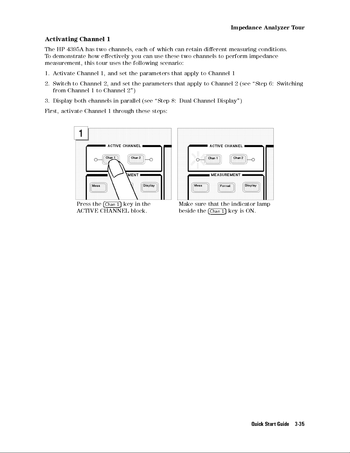
Impedance Analyzer Tour
Activating Channel 1
The HP 4395A has two channels, each of which can retain dierent measuring conditions.
To demonstrate how eectively you can use these two channels to perform impedance
measurement, this tour uses the following scenario:
1. Activate Channel 1, and set the parameters that apply to Channel 1
2. Switch to Channel 2, and set the parameters that apply to Channel 2 (see \Step 6: Switching
from Channel 1 to Channel 2")
3. Display both channels in parallel (see \Step 8: Dual Channel Display")
First, activate Channel 1 through these steps:
Press the
ACTIVE CHANNEL block.
4
Chan 1
5
key in the
Make sure that the indicator lamp
beside the
4
Chan 1
5
key is ON.
Quick Start Guide 3-35

Impedance Analyzer Tour
Setting the Sweep Parameters
This tour assumes that the frequency is being swept from 100 kHz to 500 MHz.
Follow these steps:
Press the
4
Sweep
5
key. Choose
NNNNNNNNNNNNNNNNNNNNNNNNNN
Choose
LOG FREQ
to have the
HP 4395A accept log frequency
settings.
NNNNNNNNNNNNNNNNNNNNNNNNNNNNNNNNNNNNNNNNNNNNNNN
SWEEP TYPE MENU
access the sweep type menu.
Press the
4
Start
5
key.
to
To specify the frequency at which
to start the sweep, enter
using the numeric keys.
3-36 Quick Start Guide
415405405
Press the
4
k/m
5
the unit is kHz.
key to indicate that
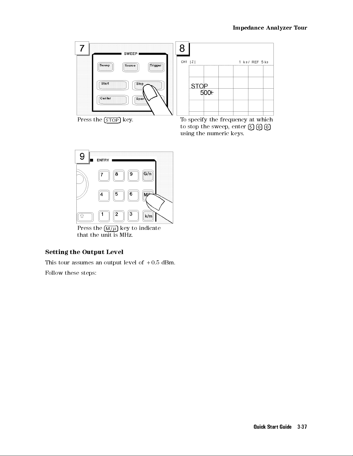
Impedance Analyzer Tour
Press the
Press the
that the unit is MHz.
Setting the Output Level
This tour assumes an output level of +0.5 dBm.
Follow these steps:
4
5
key. To specify the frequency at which
STOP
4
5
key to indicate
M/
to stop the sweep, enter
using the numeric keys.
455405405
Quick Start Guide 3-37
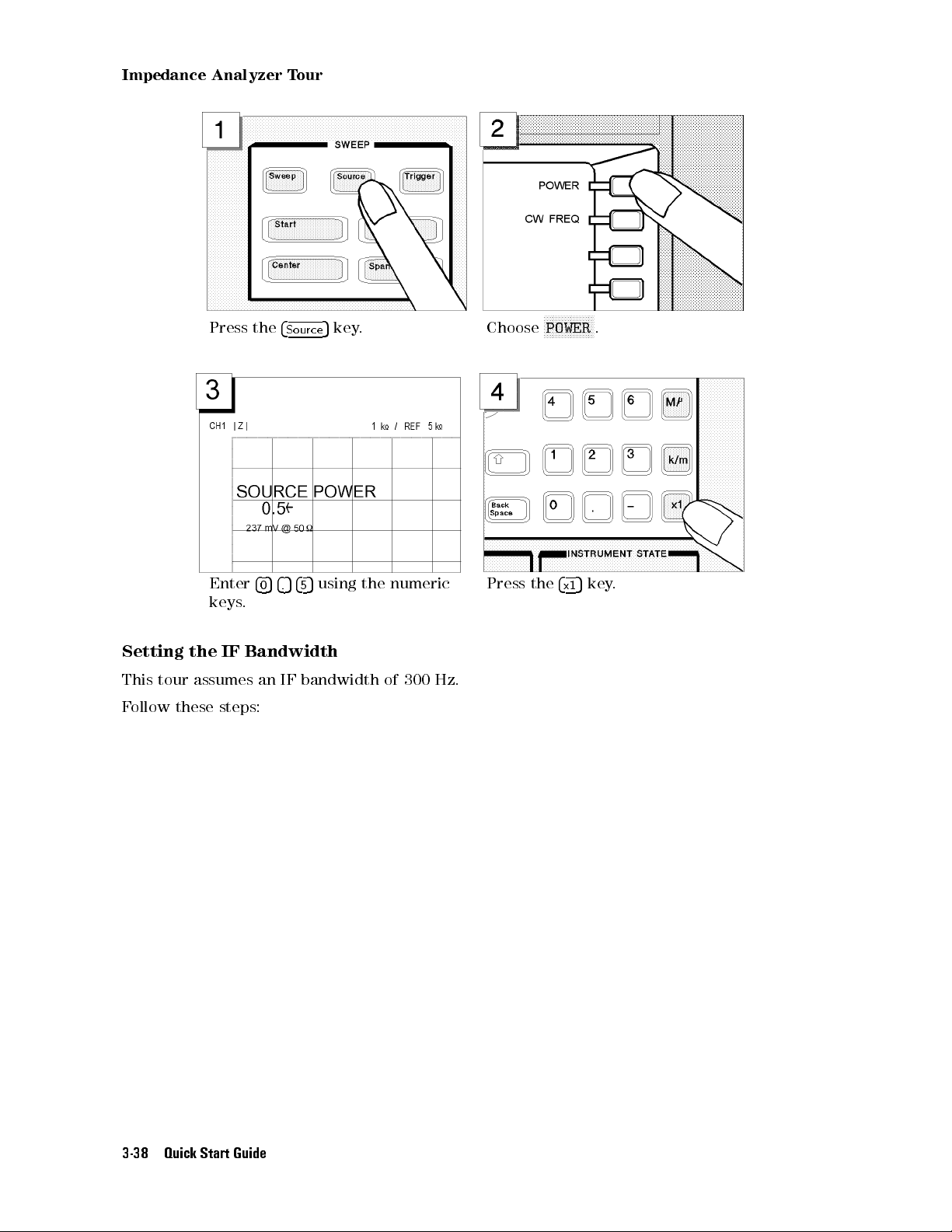
Impedance Analyzer Tour
Press the
Enter
keys.
Setting the IF Bandwidth
This tour assumes an IF bandwidth of 300 Hz.
Follow these steps:
4
4
054.545
5
Source
key. Choose
5
using the numeric
Press the
NNNNNNNNNNNNNNNNN
POWER
4
5
x1
.
key.
3-38 Quick Start Guide
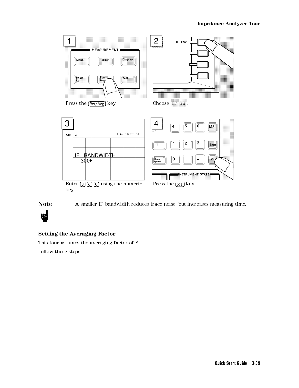
Impedance Analyzer Tour
Press the
Enter
key.
Note
Setting the Averaging Factor
4
4
3540540
A smaller IF bandwidth reduces trace noise, but increases measuring time.
5
Bw/Avg
key. Choose
5
using the numeric
Press the
NNNNNNNNNNNNNNNNN
IF BW
4
2
1
5
.
key.
This tour assumes the averaging factor of 8.
Follow these steps:
Quick Start Guide 3-39
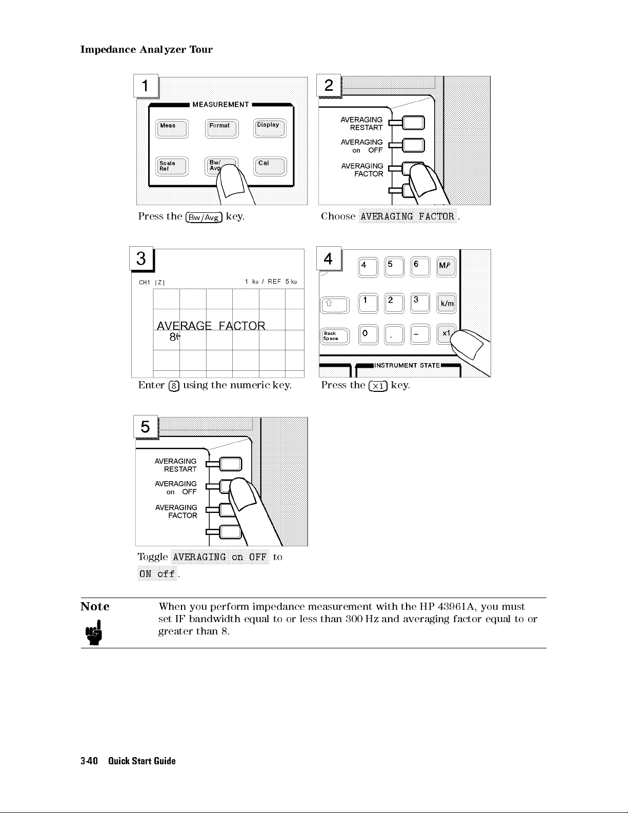
Impedance Analyzer Tour
Press the
Enter
4
8
4
5
using the numeric key. Press the
Bw/Avg
5
key. Choose
NNNNNNNNNNNNNNNNNNNNNNNNNNNNNNNNNNNNNNNNNNNNNNNNNN
AVERAGING FACTOR
4
5
key.
2
1
.
Toggle
NNNNNNNNNNNNNNNNNNNN
ON off
Note
When you perform impedance measurement with the HP 43961A, you must
set IF bandwidth equal to or less than 300 Hz and averaging factor equal to or
greater than 8.
3-40 Quick Start Guide
NNNNNNNNNNNNNNNNNNNNNNNNNNNNNNNNNNNNNNNNNNNNNNNNNN
AVERAGING on OFF
.
to

Impedance Analyzer Tour
Step 3: Making a Calibration
Calibrating the HP 4395A in impedance analyzer mode requires that the HP 4395A be
connected with the HP 43961A impedance test kit. A proper calibration is required for the
HP 4395A to perform measurements within the guaranteed accuracy range.
For impedance analyzer mode, the HP 4395A must be calibrated for each of the following three
circuit states:
OPEN (0 S termination)
SHORT (0 termination)
LOAD (50 termination)
To calibrate the HP 4395A, access the calibration menu through these steps:
Press the
With the calibration menu displayed on the LCD screen, calibrate the HP 4395A for the OPEN,
SHORT, and LOAD states in order.
Note
OPEN Calibration
Follow these steps:
4
5
key. Choose
Cal
Be sure to use the calibration kit included in the HP 43961A package
NNNNNNNNNNNNNNNNNNNNNNNNNNNNNNNNNNNNNNNNNNNN
CALIBRATE MENU
.
.
Quick Start Guide 3-41
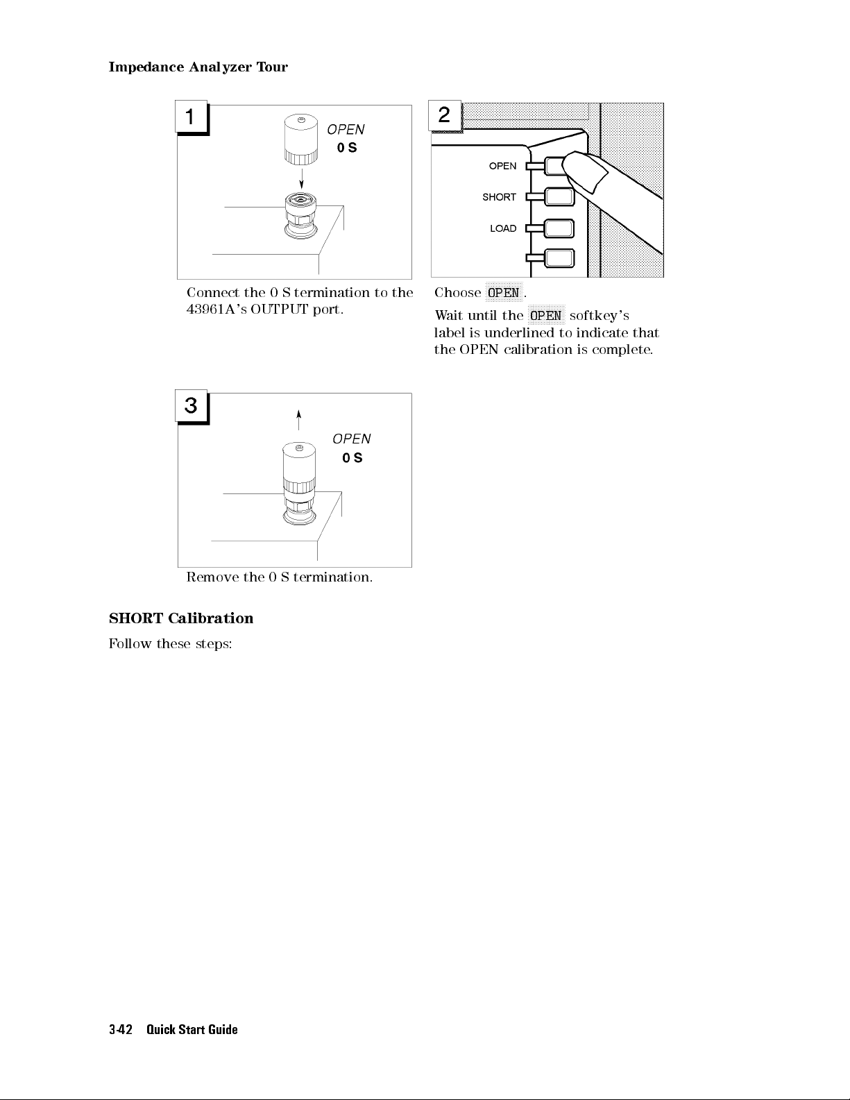
Impedance Analyzer Tour
Connect the 0 S termination to the
43961A's OUTPUT port.
Remove the 0 S termination.
SHORT Calibration
Follow these steps:
Choose
Wait until the
label is underlined to indicate that
the OPEN calibration is complete.
NNNNNNNNNNNNNN
OPEN
.
NNNNNNNNNNNNNN
OPEN
softkey's
3-42 Quick Start Guide
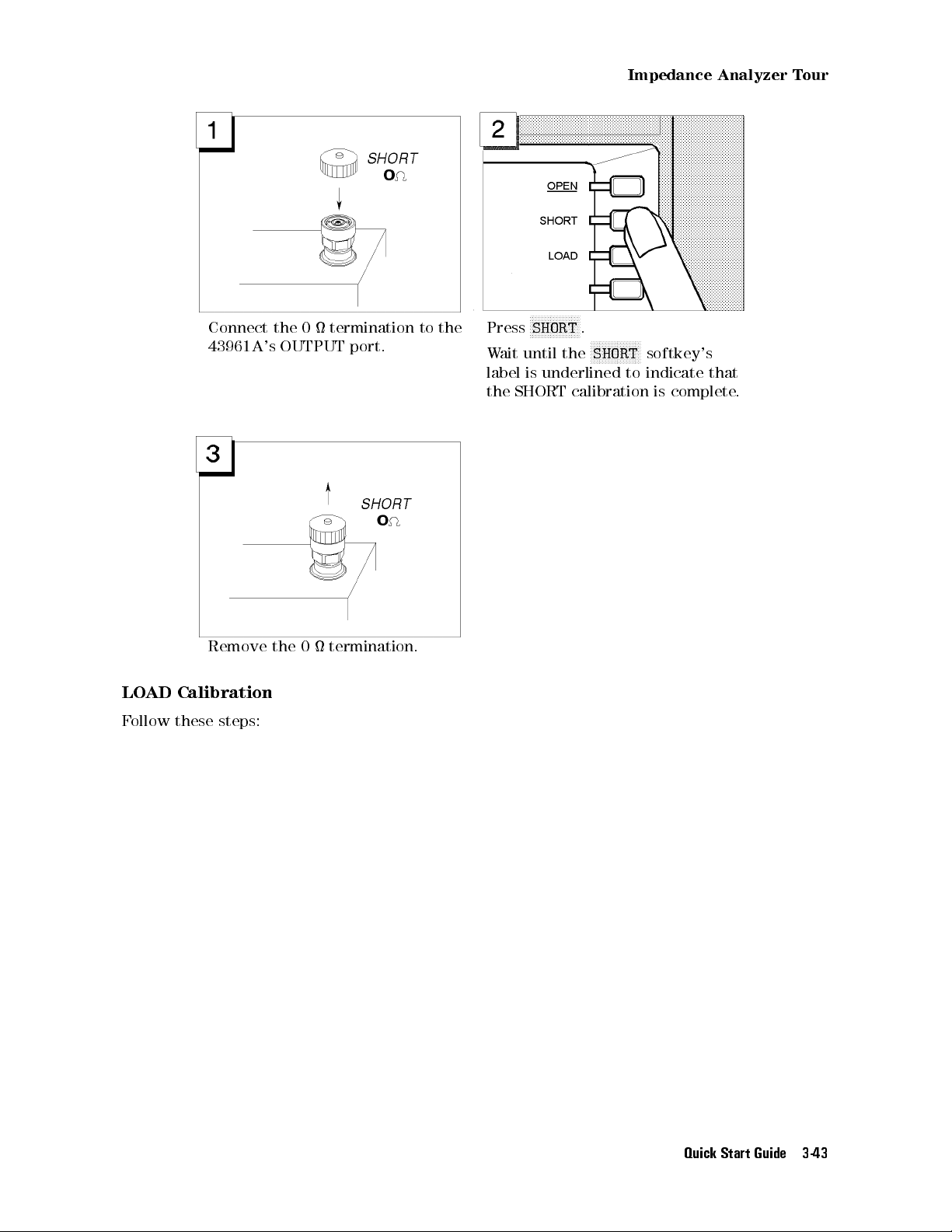
Impedance Analyzer Tour
Connect the 0 termination to the
43961A's OUTPUT port.
Remove the 0 termination.
LOAD Calibration
Follow these steps:
NNNNNNNNNNNNNNNNN
Press
SHORT
Wait until the
label is underlined to indicate that
the SHORT calibration is complete.
.
NNNNNNNNNNNNNNNNN
SHORT
softkey's
Quick Start Guide 3-43
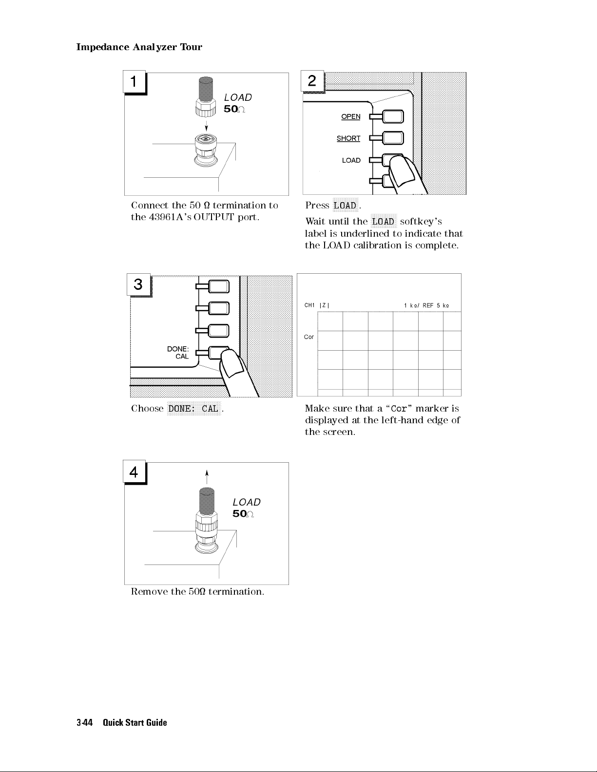
Impedance Analyzer Tour
Connect the 50 termination to
the 43961A's OUTPUT port.
Choose
NNNNNNNNNNNNNNNNNNNNNNNNNNNNN
DONE: CAL
. Make sure that a \
NNNNNNNNNNNNNN
Press
LOAD
.
Wait until the
label is underlined to indicate that
the LOAD calibration is complete.
displayed at the left-hand edge of
the screen.
NNNNNNNNNNNNNN
LOAD
softkey's
Cor
" marker is
Remove the 50 termination.
3-44 Quick Start Guide
 Loading...