

Page 1

Agilent 4294A Precision Impedance Analyzer
Service Manual
Third Edition
Manufacturing No. 04294-90110
January 2007
Page 2

Notices
The information contained in this document is subject to change without notice.
This document contains proprietary information that is protected by copyright. All rights
are reserved. No part of this document may be photocopied, reproduced, or translated to
another language without the prior written consent of Agilent Technologies.
Microsoft®,MS-DOS®,Windows®,Visual C++®,Visual Basic®,VBA® and Excel® are
registered
UNIX is a registered trademark in U.S. and other countries, licensed
exclusively through X/Open Company Limited.
Portions ©Copyright 1996, Microsoft Corporation. All rights reserved.
© Copyright 1999, 2000, 2007 Agilent Technologies
Manual Printing History
The manual’s printing date and part number indicate its current edition. The printing date
changes when a new edition is printed. (Minor corrections and updates that are
incorporated at reprint do not cause the date to change.) The manual part number changes
when extensive technical changes are incorporated.
October 1999 First Edition
June 2000 Second Edition
January 2007 Third Edition
2
Page 3

Safety Summary
The following general safety precautions must be observed during all phases of operation,
service, and repair of this instrument. Failure to comply with these precautions or with
specific WARNINGS elsewhere in this manual may impair the protection provided by the
equipment. In addition it violates safety standards of design, manufacture, and intended use
of the instrument.
The Agilent Technologies Company assumes no liability for the customer’s failure to
comply with these requirements.
NOTE 4294A comply with INSTALLATION CATEGORY II and POLLUTION DEGREE 2 in
IEC61010-1. 4294A are INDOOR USE product.
NOTE LEDs in 4294A are Class 1 in accordance with IEC60825-1.
CLASS 1 LED PRODUCT
• Ground The Instrument
To avoid electric shock hazard, the instrument chassis and cabinet must be connected to
a safety earth ground by the supplied power cable with earth blade.
• DO NOT Operate In An Explosive Atmosphere
Do not operate the instrument in the presence of flammable gasses or fumes. Operation
of any electrical instrument in such an environment constitutes a definite safety hazard.
• Keep Away From Live Circuits
Operating personnel must not remove instrument covers. Component replacement and
internal adjustments must be made by qualified maintenance personnel. Do not replace
components with the power cable connected. Under certain conditions, dangerous
voltages may exist even with the power cable removed. To avoid injuries, always
disconnect power and discharge circuits before touching them.
• DO NOT Service Or Adjust Alone
Do not attempt internal service or adjustment unless another person, capable of
rendering first aid and resuscitation, is present.
• DO NOT Substitute Parts Or Modify Instrument
Because of the danger of introducing additional hazards, do not install substitute parts
or perform unauthorized modifications to the instrument. Return the instrument to a
Agilent Technologies Sales and Service Office for service and repair to ensure that
safety features are maintained.
• Dangerous Procedure Warnings
Warnings, such as the example below, precede potentially dangerous procedures
throughout this manual. Instructions contained in the warnings must be followed.
WARNING Dangerous voltages, capable of causing death, are presenting this instrument. Use
extreme caution when handling, testing, and adjusting this instrument.
3
Page 4

Safety Symbol
General definitions of safety symbols used on the instrument or in manuals are listed
below.
Instruction Manual symbol: the product is marked with this symbol when it is necessary for
the user to refer to the instrument manual.
Alternating current.
Direct current.
On (Supply).
Off (Supply).
In position of push-button switch.
Out position of push-button switch.
Frame (or chassis) terminal. A connection to the frame (chassis) of the equipment which
normally include all exposed metal structure.
WARNING This warning sign denotes a hazard. It calls attention to a procedure, practice,
condition or the like, which, if not correctly performed or adhered to, could result in
injury or death to personnel.
CAUTION This Caution sign denotes a hazard. It calls attention to a procedure, practice, condition or
the like, which, if not correctly performed or adhered to, could result in damage to or
destruction of part or all of the product.
NOTE Note denotes important information. It calls attention to a procedure, practice, condition or
the like, which is essential to highlight.
Certification
Agilent Technologies Company certifies that this product met its published specifications
at the time of shipment from the factory. Agilent Technologies further certifies that its
calibration measurements are traceable to the United States National Institute of Standards
and Technology, to the extent allowed by the Institution’s calibration facility, or to the
calibration facilities of other International Standards Organization members.
4
Page 5

Warranty
This Agilent Technologies instrument product is warranted against defects in material and
workmanship for a period corresponding to the individual warranty periods of its
component products. Instruments are warranted for a period of one year. Fixtures and
adapters are warranted for a period of 90 days. During the warranty period, Agilent
Technologies Company will, at its option, either repair or replace products that prove to be
defective.
For warranty service or repair, this product must be returned to a service facility designated
by Agilent Technologies. Buyer shall prepay shipping charges to Agilent Technologies and
Agilent Technologies shall pay shipping charges to return the product to Buyer. However,
Buyer shall pay all shipping charges, duties, and taxes for products returned to Agilent
Technologies from another country.
Agilent Technologies warrants that its software and firmware designated by Agilent
Technologies for use with an instrument will execute its programming instruction when
property installed on that instrument. Agilent Technologies does not warrant that the
operation of the instrument, or software, or firmware will be uninterrupted or error free.
Limitation of Warranty
The foregoing warranty shall not apply to defects resulting from improper or inadequate
maintenance by Buyer, Buyer-supplied software or interfacing, unauthorized modification
or misuse, operation outside the environmental specifications for the product, or improper
site preparation or maintenance.
IMPORTANT No other warranty is expressed or implied. Agilent Technologies specifically disclaims the
implied warranties of merchantability and fitness for a particular purpose.
Exclusive Remedies
The remedies provided herein are buyer’s sole and exclusive remedies. Agilent
Technologies shall not be liable for any direct, indirect, special, incidental, or
consequential damages, whether based on contract, tort, or any other legal theory.
Assistance
Product maintenance agreements and other customer assistance agreements are available
for Agilent Technologies products.
5
Page 6

For any assistance, contact your nearest Agilent Technologies Sales and Service Office.
Addresses are provided at the back of this manual.
Typeface Conventions
Bold Boldface type is used when a term is defined. For
example: icons are symbols.
Italic Italic type is used for emphasis and for titles of
manuals and other publications.
[Hardkey] Indicates a hardkey labeled “Hardkey.”
Softkey Indicates a softkey labeled “Softkey.”
[Hardkey] - Softkey1 - Softkey2 Indicates keystrokes [Hardkey] - Softkey1 -
Softkey2.
4294A Documentation Map
The following manuals are available for the 4294A.
• Operation Manual (Agilent P/N: 04294-900x0)
Most of basic information necessary for using 4294A is described in this manual. It
includes the way of installation, preparation, measurement operation including
calibration, performances (specifications), key definitions, and error messages. For
GPIB programming, see the Programming Manual together with “HP Instrument
BASIC User's Handbook”.
• Programming Manual (Agilent P/N: 04294-900x1)
The Programming Manual shows how to write and use BASIC program to control the
4294A and describes how HP Instrument BASIC works with the analyzer.
• HP Instrument BASIC User's Handbook (Agilent P/N: E2083-90005)
The HP Instrument BASIC User’s Handbook introduces you to the HP Instrument
BASIC programming language, provide some helpful hints on getting the most use
from it, and provide a general programming reference. It is divided into three books,
HP Instrument BASIC Programming Techniques, HP Instrument BASIC Interface
Techniques, and HP Instrument BASIC Language Reference.
• Service Manual (Agilent P/N: 04294-901x0, Option 0BW only)
This manual describes how to adjust and repair the 4294A, and how to carry out
performance tests. This manual will be attached if you take the Option
0BW.
NOTE The number position shown by “x” in the part numbers above indicates the edition number.
6
Page 7

1. General Information
Organization of Service Manual . . . . . . . . . . . . . . . . . . . . . . . . . . . . . . . . . . . . . . . . . . . . . . . . . . . . . . . . . . 14
Instruments Covered by This Manual. . . . . . . . . . . . . . . . . . . . . . . . . . . . . . . . . . . . . . . . . . . . . . . . . . . . . . 15
Require Equipment . . . . . . . . . . . . . . . . . . . . . . . . . . . . . . . . . . . . . . . . . . . . . . . . . . . . . . . . . . . . . . . . . . . . 16
2. Performance Test
Performance Test . . . . . . . . . . . . . . . . . . . . . . . . . . . . . . . . . . . . . . . . . . . . . . . . . . . . . . . . . . . . . . . . . . . . . 20
Introduction . . . . . . . . . . . . . . . . . . . . . . . . . . . . . . . . . . . . . . . . . . . . . . . . . . . . . . . . . . . . . . . . . . . . . . . . 20
Test Equipment . . . . . . . . . . . . . . . . . . . . . . . . . . . . . . . . . . . . . . . . . . . . . . . . . . . . . . . . . . . . . . . . . . . . . 20
Frequency Accuracy Test . . . . . . . . . . . . . . . . . . . . . . . . . . . . . . . . . . . . . . . . . . . . . . . . . . . . . . . . . . . . . 21
OSC Level Accuracy Test . . . . . . . . . . . . . . . . . . . . . . . . . . . . . . . . . . . . . . . . . . . . . . . . . . . . . . . . . . . . . 23
DC Bias Monitor Accuracy Test . . . . . . . . . . . . . . . . . . . . . . . . . . . . . . . . . . . . . . . . . . . . . . . . . . . . . . . . 31
DC Bias Level Accuracy Test . . . . . . . . . . . . . . . . . . . . . . . . . . . . . . . . . . . . . . . . . . . . . . . . . . . . . . . . . . 35
Measurement Accuracy Test . . . . . . . . . . . . . . . . . . . . . . . . . . . . . . . . . . . . . . . . . . . . . . . . . . . . . . . . . . . 38
Calculation Sheet . . . . . . . . . . . . . . . . . . . . . . . . . . . . . . . . . . . . . . . . . . . . . . . . . . . . . . . . . . . . . . . . . . . . . 52
OSC Level Accuracy Test . . . . . . . . . . . . . . . . . . . . . . . . . . . . . . . . . . . . . . . . . . . . . . . . . . . . . . . . . . . . . 52
DC Bias Monitor Accuracy Test . . . . . . . . . . . . . . . . . . . . . . . . . . . . . . . . . . . . . . . . . . . . . . . . . . . . . . . . 54
DC Bias Level Accuracy Test . . . . . . . . . . . . . . . . . . . . . . . . . . . . . . . . . . . . . . . . . . . . . . . . . . . . . . . . . . 55
Measurement Accuracy Test . . . . . . . . . . . . . . . . . . . . . . . . . . . . . . . . . . . . . . . . . . . . . . . . . . . . . . . . . . . 56
Performance Test Record . . . . . . . . . . . . . . . . . . . . . . . . . . . . . . . . . . . . . . . . . . . . . . . . . . . . . . . . . . . . . . . 68
Frequency Accuracy Test . . . . . . . . . . . . . . . . . . . . . . . . . . . . . . . . . . . . . . . . . . . . . . . . . . . . . . . . . . . . . 68
OSC Level Accuracy Test . . . . . . . . . . . . . . . . . . . . . . . . . . . . . . . . . . . . . . . . . . . . . . . . . . . . . . . . . . . . . 69
DC Bias Monitor Accuracy Test . . . . . . . . . . . . . . . . . . . . . . . . . . . . . . . . . . . . . . . . . . . . . . . . . . . . . . . . 70
DC Bias Level Accuracy Test . . . . . . . . . . . . . . . . . . . . . . . . . . . . . . . . . . . . . . . . . . . . . . . . . . . . . . . . . . 71
Measurement Accuracy Test . . . . . . . . . . . . . . . . . . . . . . . . . . . . . . . . . . . . . . . . . . . . . . . . . . . . . . . . . . . 72
Contents
3. Adjustment
Safety Considerations . . . . . . . . . . . . . . . . . . . . . . . . . . . . . . . . . . . . . . . . . . . . . . . . . . . . . . . . . . . . . . . . . . 82
Required Controller . . . . . . . . . . . . . . . . . . . . . . . . . . . . . . . . . . . . . . . . . . . . . . . . . . . . . . . . . . . . . . . . . . . 82
Required Equipment . . . . . . . . . . . . . . . . . . . . . . . . . . . . . . . . . . . . . . . . . . . . . . . . . . . . . . . . . . . . . . . . . . . 82
Warm-up for Adjustment . . . . . . . . . . . . . . . . . . . . . . . . . . . . . . . . . . . . . . . . . . . . . . . . . . . . . . . . . . . . . . . 82
Order of Adjustment . . . . . . . . . . . . . . . . . . . . . . . . . . . . . . . . . . . . . . . . . . . . . . . . . . . . . . . . . . . . . . . . . . . 83
Preparation for using the Adjustment Program . . . . . . . . . . . . . . . . . . . . . . . . . . . . . . . . . . . . . . . . . . . . . . 84
Installing an GPIB Card (82340, 82341 or 82350) . . . . . . . . . . . . . . . . . . . . . . . . . . . . . . . . . . . . . . . . . . 84
Installing HP VEE for Personal Computer . . . . . . . . . . . . . . . . . . . . . . . . . . . . . . . . . . . . . . . . . . . . . . . . 84
Installing Adjustment Program into Your PC (preliminary). . . . . . . . . . . . . . . . . . . . . . . . . . . . . . . . . . . 84
Equipment Setup . . . . . . . . . . . . . . . . . . . . . . . . . . . . . . . . . . . . . . . . . . . . . . . . . . . . . . . . . . . . . . . . . . . . 84
Running the Adjustment Program . . . . . . . . . . . . . . . . . . . . . . . . . . . . . . . . . . . . . . . . . . . . . . . . . . . . . . . . 86
Frequency Accuracy Correction Constants . . . . . . . . . . . . . . . . . . . . . . . . . . . . . . . . . . . . . . . . . . . . . . . . . 87
Required Equipment . . . . . . . . . . . . . . . . . . . . . . . . . . . . . . . . . . . . . . . . . . . . . . . . . . . . . . . . . . . . . . . . . 87
Procedure. . . . . . . . . . . . . . . . . . . . . . . . . . . . . . . . . . . . . . . . . . . . . . . . . . . . . . . . . . . . . . . . . . . . . . . . . . 87
Image Rejection Correction Constants . . . . . . . . . . . . . . . . . . . . . . . . . . . . . . . . . . . . . . . . . . . . . . . . . . . . . 88
Required Equipment . . . . . . . . . . . . . . . . . . . . . . . . . . . . . . . . . . . . . . . . . . . . . . . . . . . . . . . . . . . . . . . . . 88
Procedure. . . . . . . . . . . . . . . . . . . . . . . . . . . . . . . . . . . . . . . . . . . . . . . . . . . . . . . . . . . . . . . . . . . . . . . . . . 88
LPOT-Mixer Offset Correction Constants . . . . . . . . . . . . . . . . . . . . . . . . . . . . . . . . . . . . . . . . . . . . . . . . . . 89
Required Equipment . . . . . . . . . . . . . . . . . . . . . . . . . . . . . . . . . . . . . . . . . . . . . . . . . . . . . . . . . . . . . . . . . 89
Procedure. . . . . . . . . . . . . . . . . . . . . . . . . . . . . . . . . . . . . . . . . . . . . . . . . . . . . . . . . . . . . . . . . . . . . . . . . . 89
Null Detector Offset Correction Constants. . . . . . . . . . . . . . . . . . . . . . . . . . . . . . . . . . . . . . . . . . . . . . . . . . 90
7
Page 8

Contents
Required Equipment . . . . . . . . . . . . . . . . . . . . . . . . . . . . . . . . . . . . . . . . . . . . . . . . . . . . . . . . . . . . . . . . . 90
Procedure . . . . . . . . . . . . . . . . . . . . . . . . . . . . . . . . . . . . . . . . . . . . . . . . . . . . . . . . . . . . . . . . . . . . . . . . . 90
Null Loop Phase Correction Constants . . . . . . . . . . . . . . . . . . . . . . . . . . . . . . . . . . . . . . . . . . . . . . . . . . . . 91
Required Equipment . . . . . . . . . . . . . . . . . . . . . . . . . . . . . . . . . . . . . . . . . . . . . . . . . . . . . . . . . . . . . . . . . 91
Procedure . . . . . . . . . . . . . . . . . . . . . . . . . . . . . . . . . . . . . . . . . . . . . . . . . . . . . . . . . . . . . . . . . . . . . . . . . 91
HPOT-Amplifier Offset Correction Constants . . . . . . . . . . . . . . . . . . . . . . . . . . . . . . . . . . . . . . . . . . . . . . . 92
Required Equipment . . . . . . . . . . . . . . . . . . . . . . . . . . . . . . . . . . . . . . . . . . . . . . . . . . . . . . . . . . . . . . . . . 92
Procedure . . . . . . . . . . . . . . . . . . . . . . . . . . . . . . . . . . . . . . . . . . . . . . . . . . . . . . . . . . . . . . . . . . . . . . . . . 92
Relative Impedance Correction Constants . . . . . . . . . . . . . . . . . . . . . . . . . . . . . . . . . . . . . . . . . . . . . . . . . . 93
Required Equipment . . . . . . . . . . . . . . . . . . . . . . . . . . . . . . . . . . . . . . . . . . . . . . . . . . . . . . . . . . . . . . . . . 93
Procedure . . . . . . . . . . . . . . . . . . . . . . . . . . . . . . . . . . . . . . . . . . . . . . . . . . . . . . . . . . . . . . . . . . . . . . . . . 93
DC Bias Monitor Correction Constants . . . . . . . . . . . . . . . . . . . . . . . . . . . . . . . . . . . . . . . . . . . . . . . . . . . . 94
Required Equipment . . . . . . . . . . . . . . . . . . . . . . . . . . . . . . . . . . . . . . . . . . . . . . . . . . . . . . . . . . . . . . . . . 94
Procedure . . . . . . . . . . . . . . . . . . . . . . . . . . . . . . . . . . . . . . . . . . . . . . . . . . . . . . . . . . . . . . . . . . . . . . . . . 94
DC Bias Level Correction Constants . . . . . . . . . . . . . . . . . . . . . . . . . . . . . . . . . . . . . . . . . . . . . . . . . . . . . . 96
Required Equipment . . . . . . . . . . . . . . . . . . . . . . . . . . . . . . . . . . . . . . . . . . . . . . . . . . . . . . . . . . . . . . . . . 96
Procedure . . . . . . . . . . . . . . . . . . . . . . . . . . . . . . . . . . . . . . . . . . . . . . . . . . . . . . . . . . . . . . . . . . . . . . . . . 96
OSC Level Monitor Correction Constants . . . . . . . . . . . . . . . . . . . . . . . . . . . . . . . . . . . . . . . . . . . . . . . . . . 97
Required Equipment . . . . . . . . . . . . . . . . . . . . . . . . . . . . . . . . . . . . . . . . . . . . . . . . . . . . . . . . . . . . . . . . . 97
Procedure . . . . . . . . . . . . . . . . . . . . . . . . . . . . . . . . . . . . . . . . . . . . . . . . . . . . . . . . . . . . . . . . . . . . . . . . . 97
OSC Level Correction Constants . . . . . . . . . . . . . . . . . . . . . . . . . . . . . . . . . . . . . . . . . . . . . . . . . . . . . . . . . 99
Required Equipment . . . . . . . . . . . . . . . . . . . . . . . . . . . . . . . . . . . . . . . . . . . . . . . . . . . . . . . . . . . . . . . . . 99
Procedure . . . . . . . . . . . . . . . . . . . . . . . . . . . . . . . . . . . . . . . . . . . . . . . . . . . . . . . . . . . . . . . . . . . . . . . . . 99
Impedance Measurement Correction Constants. . . . . . . . . . . . . . . . . . . . . . . . . . . . . . . . . . . . . . . . . . . . . 100
Required Equipment . . . . . . . . . . . . . . . . . . . . . . . . . . . . . . . . . . . . . . . . . . . . . . . . . . . . . . . . . . . . . . . . 100
Procedure . . . . . . . . . . . . . . . . . . . . . . . . . . . . . . . . . . . . . . . . . . . . . . . . . . . . . . . . . . . . . . . . . . . . . . . . 100
Frequency Reference Adjustment (Opt.1D5 only). . . . . . . . . . . . . . . . . . . . . . . . . . . . . . . . . . . . . . . . . . . 103
Required Equipment . . . . . . . . . . . . . . . . . . . . . . . . . . . . . . . . . . . . . . . . . . . . . . . . . . . . . . . . . . . . . . . . 103
Procedure . . . . . . . . . . . . . . . . . . . . . . . . . . . . . . . . . . . . . . . . . . . . . . . . . . . . . . . . . . . . . . . . . . . . . . . . 103
4. Troubleshooting
TROUBLESHOOTING SUMMARY . . . . . . . . . . . . . . . . . . . . . . . . . . . . . . . . . . . . . . . . . . . . . . . . . . . . 106
START HERE. . . . . . . . . . . . . . . . . . . . . . . . . . . . . . . . . . . . . . . . . . . . . . . . . . . . . . . . . . . . . . . . . . . . . . . 108
INSPECT THE POWER ON SEQUENCE . . . . . . . . . . . . . . . . . . . . . . . . . . . . . . . . . . . . . . . . . . . . . . . . 109
Check the Fan . . . . . . . . . . . . . . . . . . . . . . . . . . . . . . . . . . . . . . . . . . . . . . . . . . . . . . . . . . . . . . . . . . . . . 109
Check the Front Panel LEDs and Displays. . . . . . . . . . . . . . . . . . . . . . . . . . . . . . . . . . . . . . . . . . . . . . . 109
Check Error Message . . . . . . . . . . . . . . . . . . . . . . . . . . . . . . . . . . . . . . . . . . . . . . . . . . . . . . . . . . . . . . . 109
INSPECT THE REAR PANEL FEATURE . . . . . . . . . . . . . . . . . . . . . . . . . . . . . . . . . . . . . . . . . . . . . . . . 110
Check the GPIB Interface . . . . . . . . . . . . . . . . . . . . . . . . . . . . . . . . . . . . . . . . . . . . . . . . . . . . . . . . . . . . 110
Check the Parallel Interface . . . . . . . . . . . . . . . . . . . . . . . . . . . . . . . . . . . . . . . . . . . . . . . . . . . . . . . . . . 110
Check the mini DIN Keyboard Connector . . . . . . . . . . . . . . . . . . . . . . . . . . . . . . . . . . . . . . . . . . . . . . . 110
Internal Tests Failure Troubleshooting. . . . . . . . . . . . . . . . . . . . . . . . . . . . . . . . . . . . . . . . . . . . . . . . . . . . 111
Check the Power-On Selftest . . . . . . . . . . . . . . . . . . . . . . . . . . . . . . . . . . . . . . . . . . . . . . . . . . . . . . . . . 111
Execute All Internal Tests. . . . . . . . . . . . . . . . . . . . . . . . . . . . . . . . . . . . . . . . . . . . . . . . . . . . . . . . . . . . 111
Execute the Individual Test. . . . . . . . . . . . . . . . . . . . . . . . . . . . . . . . . . . . . . . . . . . . . . . . . . . . . . . . . . . 111
External Tests Failure Troubleshooting . . . . . . . . . . . . . . . . . . . . . . . . . . . . . . . . . . . . . . . . . . . . . . . . . . . 113
Performance Tests Failure Troubleshooting. . . . . . . . . . . . . . . . . . . . . . . . . . . . . . . . . . . . . . . . . . . . . . . . 115
Perform Adjustments and Correction Constants . . . . . . . . . . . . . . . . . . . . . . . . . . . . . . . . . . . . . . . . . . 115
8
Page 9

5. Power Supply Troubleshooting
INTRODUCTION . . . . . . . . . . . . . . . . . . . . . . . . . . . . . . . . . . . . . . . . . . . . . . . . . . . . . . . . . . . . . . . . . . . 118
START HERE. . . . . . . . . . . . . . . . . . . . . . . . . . . . . . . . . . . . . . . . . . . . . . . . . . . . . . . . . . . . . . . . . . . . . . . 120
1. Check the Fan . . . . . . . . . . . . . . . . . . . . . . . . . . . . . . . . . . . . . . . . . . . . . . . . . . . . . . . . . . . . . . . . . . . 120
2.Check the A50 SHUTDOWN LED . . . . . . . . . . . . . . . . . . . . . . . . . . . . . . . . . . . . . . . . . . . . . . . . . . . 120
A50 Shutdown LED . . . . . . . . . . . . . . . . . . . . . . . . . . . . . . . . . . . . . . . . . . . . . . . . . . . . . . . . . . . . . . . . 121
3.Check the A50 Five LEDs . . . . . . . . . . . . . . . . . . . . . . . . . . . . . . . . . . . . . . . . . . . . . . . . . . . . . . . . . . 121
4. Check the A1 +5 VD LED . . . . . . . . . . . . . . . . . . . . . . . . . . . . . . . . . . . . . . . . . . . . . . . . . . . . . . . . . 121
5. Check the A9 Two LEDs . . . . . . . . . . . . . . . . . . . . . . . . . . . . . . . . . . . . . . . . . . . . . . . . . . . . . . . . . . 122
FIND OUT WHY THE FAN IS NOT ROTATING . . . . . . . . . . . . . . . . . . . . . . . . . . . . . . . . . . . . . . . . . . 125
1. Check the Line Voltage, Selector Switch Setting, and Fuse . . . . . . . . . . . . . . . . . . . . . . . . . . . . . . . . 125
2. Check the A40 Pre-Regulator . . . . . . . . . . . . . . . . . . . . . . . . . . . . . . . . . . . . . . . . . . . . . . . . . . . . . . . 125
3. Check the A50 SHUTDOWN LED . . . . . . . . . . . . . . . . . . . . . . . . . . . . . . . . . . . . . . . . . . . . . . . . . . 126
FIND OUT WHY THE A50 SHUTDOWN LED IS OFF . . . . . . . . . . . . . . . . . . . . . . . . . . . . . . . . . . . . . 127
1. Disconnect the Cable from the A50P3 . . . . . . . . . . . . . . . . . . . . . . . . . . . . . . . . . . . . . . . . . . . . . . . . 127
2. Remove A50 . . . . . . . . . . . . . . . . . . . . . . . . . . . . . . . . . . . . . . . . . . . . . . . . . . . . . . . . . . . . . . . . . . . . 127
3. Remove Assemblies . . . . . . . . . . . . . . . . . . . . . . . . . . . . . . . . . . . . . . . . . . . . . . . . . . . . . . . . . . . . . . 127
FIND OUT WHY THE A1 +5 VD LED IS NOT ON STEADILY . . . . . . . . . . . . . . . . . . . . . . . . . . . . . . 128
1. Check the A50 DC-DC Converter . . . . . . . . . . . . . . . . . . . . . . . . . . . . . . . . . . . . . . . . . . . . . . . . . . . 128
2. Measure the A1 +5VD Voltage. . . . . . . . . . . . . . . . . . . . . . . . . . . . . . . . . . . . . . . . . . . . . . . . . . . . . . 128
3. Disconnect Cables on the A1 CPU . . . . . . . . . . . . . . . . . . . . . . . . . . . . . . . . . . . . . . . . . . . . . . . . . . . 128
3. Remove Assemblies . . . . . . . . . . . . . . . . . . . . . . . . . . . . . . . . . . . . . . . . . . . . . . . . . . . . . . . . . . . . . . 129
TROUBLSHOOT THE FAN AND THE A50 DC-DC CONVERTER . . . . . . . . . . . . . . . . . . . . . . . . . . . 131
1. Troubleshoot the Fan. . . . . . . . . . . . . . . . . . . . . . . . . . . . . . . . . . . . . . . . . . . . . . . . . . . . . . . . . . . . . . 131
2. Troubleshoot the A50 DC-DC Converter . . . . . . . . . . . . . . . . . . . . . . . . . . . . . . . . . . . . . . . . . . . . . . 132
Contents
6. Digital Control Troubleshooting
INTRODUCTION . . . . . . . . . . . . . . . . . . . . . . . . . . . . . . . . . . . . . . . . . . . . . . . . . . . . . . . . . . . . . . . . . . . 134
A1 CPU Replacement. . . . . . . . . . . . . . . . . . . . . . . . . . . . . . . . . . . . . . . . . . . . . . . . . . . . . . . . . . . . . . . . . 136
FIRMWARE INSTALLATION . . . . . . . . . . . . . . . . . . . . . . . . . . . . . . . . . . . . . . . . . . . . . . . . . . . . . . . . . 137
Ordering the Firmware Diskette . . . . . . . . . . . . . . . . . . . . . . . . . . . . . . . . . . . . . . . . . . . . . . . . . . . . . . . 137
Installing the Firmware . . . . . . . . . . . . . . . . . . . . . . . . . . . . . . . . . . . . . . . . . . . . . . . . . . . . . . . . . . . . . . 137
START HERE. . . . . . . . . . . . . . . . . . . . . . . . . . . . . . . . . . . . . . . . . . . . . . . . . . . . . . . . . . . . . . . . . . . . . . . 139
1. Check the Power-On Sequence. . . . . . . . . . . . . . . . . . . . . . . . . . . . . . . . . . . . . . . . . . . . . . . . . . . . . . 139
2. Check the A1 CPU . . . . . . . . . . . . . . . . . . . . . . . . . . . . . . . . . . . . . . . . . . . . . . . . . . . . . . . . . . . . . . . 141
3. Check the A1 DRAM and Flash Memory. . . . . . . . . . . . . . . . . . . . . . . . . . . . . . . . . . . . . . . . . . . . . . 141
4. Check the A1 Volatile Memory. . . . . . . . . . . . . . . . . . . . . . . . . . . . . . . . . . . . . . . . . . . . . . . . . . . . . . 142
5. Check the A30 Front Keyboard . . . . . . . . . . . . . . . . . . . . . . . . . . . . . . . . . . . . . . . . . . . . . . . . . . . . . 142
6. Check the A53 FDD . . . . . . . . . . . . . . . . . . . . . . . . . . . . . . . . . . . . . . . . . . . . . . . . . . . . . . . . . . . . . . 143
7. Check the A32 I-BASIC Interface and the mini DIN Keyboard . . . . . . . . . . . . . . . . . . . . . . . . . . . . 143
8. Check the 24 BIT I/O PORT . . . . . . . . . . . . . . . . . . . . . . . . . . . . . . . . . . . . . . . . . . . . . . . . . . . . . . . . 143
9. Check the LAN Operation. . . . . . . . . . . . . . . . . . . . . . . . . . . . . . . . . . . . . . . . . . . . . . . . . . . . . . . . . . 144
TROUBLESHOOT THE A51 GSP and A52 LCD . . . . . . . . . . . . . . . . . . . . . . . . . . . . . . . . . . . . . . . . . . 146
1. Run the Internal Test 4: A51 GSP. . . . . . . . . . . . . . . . . . . . . . . . . . . . . . . . . . . . . . . . . . . . . . . . . . . . 146
2. Check the A52 LCD (Liquid Crystal Display) . . . . . . . . . . . . . . . . . . . . . . . . . . . . . . . . . . . . . . . . . . 146
7. Service Related Menus
DIAGNOSTIC TEST Menu . . . . . . . . . . . . . . . . . . . . . . . . . . . . . . . . . . . . . . . . . . . . . . . . . . . . . . . . . . . . 148
9
Page 10

Contents
Test Status . . . . . . . . . . . . . . . . . . . . . . . . . . . . . . . . . . . . . . . . . . . . . . . . . . . . . . . . . . . . . . . . . . . . . . . . 148
Test Descriptions. . . . . . . . . . . . . . . . . . . . . . . . . . . . . . . . . . . . . . . . . . . . . . . . . . . . . . . . . . . . . . . . . . . 149
8. Theory of Operation
OVERALL OPERATION . . . . . . . . . . . . . . . . . . . . . . . . . . . . . . . . . . . . . . . . . . . . . . . . . . . . . . . . . . . . . 156
OVERALL MEASUREMENT THEORY . . . . . . . . . . . . . . . . . . . . . . . . . . . . . . . . . . . . . . . . . . . . . . . 156
OVERALL OPERATION AND FUNCTIONAL GROUPS . . . . . . . . . . . . . . . . . . . . . . . . . . . . . . . . . 156
POWER SUPPLY OPERATION . . . . . . . . . . . . . . . . . . . . . . . . . . . . . . . . . . . . . . . . . . . . . . . . . . . . . . . . 158
Line Power Module . . . . . . . . . . . . . . . . . . . . . . . . . . . . . . . . . . . . . . . . . . . . . . . . . . . . . . . . . . . . . . . . 159
A40 Preregulator. . . . . . . . . . . . . . . . . . . . . . . . . . . . . . . . . . . . . . . . . . . . . . . . . . . . . . . . . . . . . . . . . . . 160
A50 DC-DC Converter . . . . . . . . . . . . . . . . . . . . . . . . . . . . . . . . . . . . . . . . . . . . . . . . . . . . . . . . . . . . . . 160
Regulated + 5V Digital Supply( + 5VD) . . . . . . . . . . . . . . . . . . . . . . . . . . . . . . . . . . . . . . . . . . . . . . . . 160
A50 Shutdown LED . . . . . . . . . . . . . . . . . . . . . . . . . . . . . . . . . . . . . . . . . . . . . . . . . . . . . . . . . . . . . . . . 160
A9 Floating Power Supply . . . . . . . . . . . . . . . . . . . . . . . . . . . . . . . . . . . . . . . . . . . . . . . . . . . . . . . . . . . 160
DIGITAL CONTROL OPERATION . . . . . . . . . . . . . . . . . . . . . . . . . . . . . . . . . . . . . . . . . . . . . . . . . . . . . 161
A1 CPU. . . . . . . . . . . . . . . . . . . . . . . . . . . . . . . . . . . . . . . . . . . . . . . . . . . . . . . . . . . . . . . . . . . . . . . . . . 163
A30 Front Keyboard . . . . . . . . . . . . . . . . . . . . . . . . . . . . . . . . . . . . . . . . . . . . . . . . . . . . . . . . . . . . . . . . 163
A32 I-BASIC Interface. . . . . . . . . . . . . . . . . . . . . . . . . . . . . . . . . . . . . . . . . . . . . . . . . . . . . . . . . . . . . . 163
A34 I/O Connector . . . . . . . . . . . . . . . . . . . . . . . . . . . . . . . . . . . . . . . . . . . . . . . . . . . . . . . . . . . . . . . . . 163
A51 GSP . . . . . . . . . . . . . . . . . . . . . . . . . . . . . . . . . . . . . . . . . . . . . . . . . . . . . . . . . . . . . . . . . . . . . . . . . 164
A54 Inverter . . . . . . . . . . . . . . . . . . . . . . . . . . . . . . . . . . . . . . . . . . . . . . . . . . . . . . . . . . . . . . . . . . . . . . 164
A52 LCD (Liquid Crystal Display) . . . . . . . . . . . . . . . . . . . . . . . . . . . . . . . . . . . . . . . . . . . . . . . . . . . . 164
A53 FDD. . . . . . . . . . . . . . . . . . . . . . . . . . . . . . . . . . . . . . . . . . . . . . . . . . . . . . . . . . . . . . . . . . . . . . . . . 164
SOURCE THEORY . . . . . . . . . . . . . . . . . . . . . . . . . . . . . . . . . . . . . . . . . . . . . . . . . . . . . . . . . . . . . . . . . . 165
A7 Synthesizer . . . . . . . . . . . . . . . . . . . . . . . . . . . . . . . . . . . . . . . . . . . . . . . . . . . . . . . . . . . . . . . . . . . . 165
A2 Hc Amp. . . . . . . . . . . . . . . . . . . . . . . . . . . . . . . . . . . . . . . . . . . . . . . . . . . . . . . . . . . . . . . . . . . . . . . 166
TRANSDUCER THEORY . . . . . . . . . . . . . . . . . . . . . . . . . . . . . . . . . . . . . . . . . . . . . . . . . . . . . . . . . . . . 167
A3 Hp Amp. . . . . . . . . . . . . . . . . . . . . . . . . . . . . . . . . . . . . . . . . . . . . . . . . . . . . . . . . . . . . . . . . . . . . . . 168
A4 Lc Amp. . . . . . . . . . . . . . . . . . . . . . . . . . . . . . . . . . . . . . . . . . . . . . . . . . . . . . . . . . . . . . . . . . . . . . . 168
A5 IV Converter & Lp Amp. . . . . . . . . . . . . . . . . . . . . . . . . . . . . . . . . . . . . . . . . . . . . . . . . . . . . . . . . . 168
A6 Vector Generator . . . . . . . . . . . . . . . . . . . . . . . . . . . . . . . . . . . . . . . . . . . . . . . . . . . . . . . . . . . . . . . . 168
VECTOR RATIO DETECTOR THEORY. . . . . . . . . . . . . . . . . . . . . . . . . . . . . . . . . . . . . . . . . . . . . . . . . 169
A8 Vector Ratio Detector . . . . . . . . . . . . . . . . . . . . . . . . . . . . . . . . . . . . . . . . . . . . . . . . . . . . . . . . . . . . 169
9. Parts Replacement
Replaceable Part List . . . . . . . . . . . . . . . . . . . . . . . . . . . . . . . . . . . . . . . . . . . . . . . . . . . . . . . . . . . . . . . . . 172
Ordering Information . . . . . . . . . . . . . . . . . . . . . . . . . . . . . . . . . . . . . . . . . . . . . . . . . . . . . . . . . . . . . . . 172
Exchange Assemblies . . . . . . . . . . . . . . . . . . . . . . . . . . . . . . . . . . . . . . . . . . . . . . . . . . . . . . . . . . . . . . . 172
Parts List . . . . . . . . . . . . . . . . . . . . . . . . . . . . . . . . . . . . . . . . . . . . . . . . . . . . . . . . . . . . . . . . . . . . . . . . . 173
Replacement Procedure . . . . . . . . . . . . . . . . . . . . . . . . . . . . . . . . . . . . . . . . . . . . . . . . . . . . . . . . . . . . . . . 203
Top Cover Removal . . . . . . . . . . . . . . . . . . . . . . . . . . . . . . . . . . . . . . . . . . . . . . . . . . . . . . . . . . . . . . . . 203
Bottom Cover Removal . . . . . . . . . . . . . . . . . . . . . . . . . . . . . . . . . . . . . . . . . . . . . . . . . . . . . . . . . . . . . 203
Side Cover Removal . . . . . . . . . . . . . . . . . . . . . . . . . . . . . . . . . . . . . . . . . . . . . . . . . . . . . . . . . . . . . . . . 203
Front Panel Removal . . . . . . . . . . . . . . . . . . . . . . . . . . . . . . . . . . . . . . . . . . . . . . . . . . . . . . . . . . . . . . . 204
Rear Panel Removal . . . . . . . . . . . . . . . . . . . . . . . . . . . . . . . . . . . . . . . . . . . . . . . . . . . . . . . . . . . . . . . . 204
A1 CPU Board Replacement . . . . . . . . . . . . . . . . . . . . . . . . . . . . . . . . . . . . . . . . . . . . . . . . . . . . . . . . . 205
A2/A8/A50/A51 Replacement . . . . . . . . . . . . . . . . . . . . . . . . . . . . . . . . . . . . . . . . . . . . . . . . . . . . . . . . 205
A3 Hp Amplifier Replacement . . . . . . . . . . . . . . . . . . . . . . . . . . . . . . . . . . . . . . . . . . . . . . . . . . . . . . . . 205
10
Page 11

A4 Lc Amplifier Replacement . . . . . . . . . . . . . . . . . . . . . . . . . . . . . . . . . . . . . . . . . . . . . . . . . . . . . . . . 206
A5 IV Convertor & Lp Amplifier Replacement . . . . . . . . . . . . . . . . . . . . . . . . . . . . . . . . . . . . . . . . . . . 206
A6 Vector Generator Replacement . . . . . . . . . . . . . . . . . . . . . . . . . . . . . . . . . . . . . . . . . . . . . . . . . . . . . 206
A7 Synthesizer Replacement . . . . . . . . . . . . . . . . . . . . . . . . . . . . . . . . . . . . . . . . . . . . . . . . . . . . . . . . . 207
A9 Floating Power Supply Replacement . . . . . . . . . . . . . . . . . . . . . . . . . . . . . . . . . . . . . . . . . . . . . . . . 207
A53 FDD Removal . . . . . . . . . . . . . . . . . . . . . . . . . . . . . . . . . . . . . . . . . . . . . . . . . . . . . . . . . . . . . . . . . 208
A52 LCD Removal . . . . . . . . . . . . . . . . . . . . . . . . . . . . . . . . . . . . . . . . . . . . . . . . . . . . . . . . . . . . . . . . . 209
A40 Preregulator Replacement . . . . . . . . . . . . . . . . . . . . . . . . . . . . . . . . . . . . . . . . . . . . . . . . . . . . . . . . 209
Power Switch Replacement. . . . . . . . . . . . . . . . . . . . . . . . . . . . . . . . . . . . . . . . . . . . . . . . . . . . . . . . . . . 210
10. Post Repair Procedures
POST REPAIR PROCEDURES. . . . . . . . . . . . . . . . . . . . . . . . . . . . . . . . . . . . . . . . . . . . . . . . . . . . . . . . . 214
A. Manual Changes
Manual Changes . . . . . . . . . . . . . . . . . . . . . . . . . . . . . . . . . . . . . . . . . . . . . . . . . . . . . . . . . . . . . . . . . . . . . 218
Contents
B. Power Requirement
Replacing Fuse . . . . . . . . . . . . . . . . . . . . . . . . . . . . . . . . . . . . . . . . . . . . . . . . . . . . . . . . . . . . . . . . . . . . . . 220
Fuse Selection . . . . . . . . . . . . . . . . . . . . . . . . . . . . . . . . . . . . . . . . . . . . . . . . . . . . . . . . . . . . . . . . . . . . . 220
Power Requirements . . . . . . . . . . . . . . . . . . . . . . . . . . . . . . . . . . . . . . . . . . . . . . . . . . . . . . . . . . . . . . . . . . 221
Power Cable . . . . . . . . . . . . . . . . . . . . . . . . . . . . . . . . . . . . . . . . . . . . . . . . . . . . . . . . . . . . . . . . . . . . . . 221
C. Error messages
Order of Alphabet . . . . . . . . . . . . . . . . . . . . . . . . . . . . . . . . . . . . . . . . . . . . . . . . . . . . . . . . . . . . . . . . . . . . 224
11
Page 12

Contents
12
Page 13

1. General Information
1 General Information
This Service Manual is a guide to servicing the 4294A Precision Impedance Analyzer. The
Service Manual provides information about performance testing, adjusting,
troubleshooting, and repairing the 4294A.
13
Page 14

General Information
Organization of Service Manual
Organization of Service Manual
This manual consists of the major chapters listed below. This section describes the names
of the chapters and the content of each chapter.
• Performance Test provides procedures for performance testing the 4294A.
• Adjustment provides procedures for adjusting the 4294A after repair or replacement of
an assembly. Most of the adjustments update the correction constants stored into the
EEPROM on the A1 CPU. The correction constants are updated by using the
adjustment program.
• Troubleshooting provides troubleshooting procedures to isolate any faulty functional
group or faulty assembly. Faulty assembly isolation procedures for the faulty functional
group follow this chapter.
• Power Supply Troubleshooting provides troubleshooting procedures to isolate any
faulty assembly within the power supply functional group.
• Digital Control Troubleshooting provides troubleshooting procedures to isolate any
faulty assembly within the digital control functional group.
• Service Related Menus documents the functions of the menus accessed from [System],
DIAGNOSTIC TEST. These menus are used to test, verify, and troubleshoot the 4294A.
• Theory of Operation explains the overall operation of the 4294A, the division into
functional groups, and the operation of each functional group.
• Parts Replacement provides part numbers and illustrations of the replaceable
assemblies and miscellaneous chassis parts. This chapter also provides procedures to
disassemble portions of the analyzer when certain assemblies have to be replaced.
• Post Repair Procedures contains the table of related service procedures. It is a table of
adjustments and verification procedures to be performed after repair or replacement of
each assembly.
• Appendices contains manual change information (required to make this manual
compatible with earlier shipment configurations of the analyzer), power requirements
and error messages of the analyzer.
14 1
Page 15
Instruments Covered by This Manual
Agilent Technologies uses a two-part, ten-character serial number label (See Figure 1-1)
attached to the instrument’s rear panel. The first five characters are the serial prefix and the
last five digits are the suffix.
Figure 1-1 Serial Number Label
An instrument manufactured after the printing date of this manual may have serial number
prefix that is not listed on the title page. This unlisted serial number prefix indicates the
instrument is different from those described in this manual. The manual for this new
instrument may be accompanied by a yellow Manual Changes supplement or have a
different manual part number. This sheet contains “change information” that explains how
to adapt the manual to the newer instrument.
General Information
Instruments Covered by This Manual
1. General Information
In addition to change information, the supplement may contain information for correcting
errors (Errata) in the manual. To keep this manual as current and accurate as possible,
Agilent Technologies recommends that you periodically request the latest Manual Changes
supplement. The supplement for this manual is identified by this manual’s printing data
and is available from Agilent Technologies. If the serial prefix or number of an instrument
is lower than that on the title page of this manual, see Appendix A, Manual Changes. For
information concerning, a serial number prefix that is not listed on the title page or in the
Manual Changes supplement, contact the nearest Agilent Technologies office.
1 15
Page 16

General Information
Require Equipment
Require Equipment
Table 1-1 lists the recommended equipment for performing maintenance on the 4294A.
Table 1-1 Recommended Test Equipment
Equipment Critical Specifications Recommended Model Qty.
Frequency Counter Frequency Range: 10 MHz, Time
Base Error: ≤ ±1.9×10
–7
/year
Frequency Standard Frequency: 10 MHz, Time Base Error:
–10
≤ ±1×10
/year
5334B,
or 53181A
5061B,
or 5071A
1 P, A
1 P, A
Use
Multimeter No Substitute 3458A 1 P, A
Power Meter No Substitute 437B,
1 P, A
438A,
E4418A/B,
or E4419A/B
Power Sensor Frequency Range: 1 MHz to 110 MHz
8482A 1 P, A
Power: –30 dBm to 20 dBm
Standard Capacitor No substitute 16380A 1 P, A
Standard Capacitor No substitute 16380C 1 P
Standard Resistor No substitute 42030A 1 P
4TP OPEN termination No substitute 42090A 1 P, A
*1
4TP SHORT termination No substitute 42091A 1 P, A
Performance Test Kit No substitute 16190A 1 P
7mm Terminal Adapter No substitute 42942A 1 P
Test Leads 1m No substitute
Test Leads 2m No substitute
100 Ω Resistor No substitute
4TP to BNC Interface
No substitute p/n 04294-61002 1 P, A
16048G
16048H
p/n 04294-61001
*2
*2
*3
1 P
1 P
1 P, A
Box
Two-Way Power Splitter Frequency Range 1 MHz to 110 MHz,
11667A 1 P, A
Output Tracking ≤ 0.15 dB
Cables BNC(m)-BNC(m) Cable, 61 cm
Banana(m)-Banana(m) Cable
p/n 8120-1839
11058A
1
2
P, A
A
16 1
Page 17

Table 1-1 Recommended Test Equipment
General Information
Require Equipment
1. General Information
Equipment Critical Specifications Recommended Model Qty.
Adapter 7 mm-N(m) Adapter
Dual Banana-BNC(f) Adapter
N(m)-BNC(m) Adapter
BNC(f)-BNC(f) Adapter
BNC(m)-Banana(m) Adapter
11525A
p/n 1251-2277
p/n 1250-0077
p/n 1250-1830
p/n 1250-1263
1
1
1
4
4
Use
P
P, A
P, A
A
A
Termination 50 Ω termination 909C Opt.012 1 P, A
*1.P:Performance Test A:Adjustment
*2.16048A/D cannot be used for a substitute.
*3.furnished with the 4294A
*1
1 17
Page 18

General Information
Require Equipment
18 1
Page 19

2. Performance Test
2 Performance Test
This chapter contains the performance test for the 4294A Precision Impedance Analyzer.
These performance tests are used to verify that the analyzer’s performance meets its
specifications.
19
Page 20

Performance Test
Performance Test
Performance Test
Introduction
This section provides the test procedures used to verify that the 4294A’s specifications are
met. The performance tests can also be used for incoming inspection, and for verification
after troubleshooting or adjustment. If the performance tests indicate that the 4294A is
NOT operating within the specified limits, check your test setup, then proceed with
troubleshooting if necessary.
War m Up Time
Allow the 4294A to warm up for at least 30 minutes before you execute any of the
performance tests
Ambient Conditions
Perform all performance tests in ambient conditions of 23 °C ± 5 °C, ≤ 70% RH.
Performance Test Interval
The performance test should be performed periodically. The recommended test interval is
12 months.
NOTE The test interval depends on maintenance of use and the environmental conditions under
which the instrument is used. You may find that the test interval could be shortened or
lengthened; however, such a decision should be based on substantial quantitative data.
Performance Test Record and Calculation Sheet
Performance test record lists all test points, acceptable test limits, test result entry columns,
and measurement uncertainties. The listed measurement uncertainties are valid only when
the recommended test equipment is used.
The calculation sheet is used as an aid for recording raw measurement data, and for
calculating the performance test results.
The procedure for using the calculation sheet and performance test record is;
1. Photo copy the calculation sheet.
2. Follow the performance test procedure and record the measurement values, the
4294A’s reading, etc., into the specified column on the calculation sheet.
3. Calculate the test result using the appropriate equation given on the calculation sheet,
and record the test result into the Test Result column of the performance test record.
Test Equipment
Table 1-1 lists the recommended equipment for performing maintenance on the 4294A.
20 2
Page 21
Performance Test
Performance Test
Frequency Accuracy Test
This test checks the frequency accuracy of the internal frequency reference with a
frequency counter and a frequency standard.
Specification
Frequency Accuracy: ± 20 ppm at (23±5) ºC (without Option 1D5)
± 0.13 ppm at 0 ºC to 55 ºC (with Option 1D5)
Test Equipment
Description Recommended Model
Frequency Counter 5334B or 53181A
Frequency Standard 5071A
4TP to BNC Interface Box p/n 04294-61002
BNC(m) -BNC(m) Cable, 61 cm p/n 8120-1839
2. Performance Test
BNC(m)-BNC(m) Cable, 122 cm p/n 8120-1840
Procedure
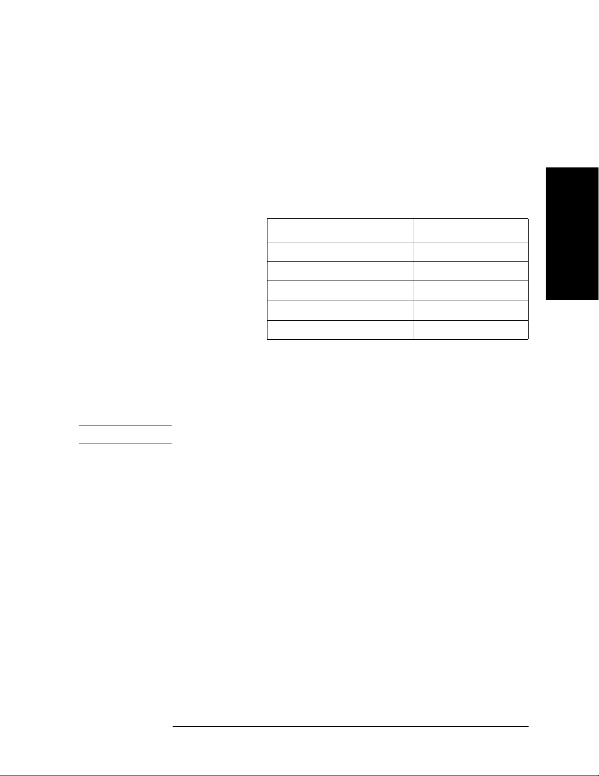
1. Connect the test equipment as shown in Figure 2-1. For testing the 4294A with Option
1D5, connect a BNC(m)-BNC(m) cable between the EXT REF Input connector and the
REF OVEN connector on the analyzer rear panel.
NOTE If testing the 4294A without Option 1D5, the frequency standard is not required.
2 21
Page 22
Performance Test
Performance Test
Figure 2-1 Frequency Accuracy Test Setup
2. Initialize the frequency counter. Then set the controls as follows.
Gate Time: 1 sec.
INT/EXT Switch (rear panel, 5334B only)
*1.If the frequency standard is not connected, set the switch to INT.
EXT
*1
3. Press [Preset] to initialize the 4294A. Then set the controls as follows.
Setting Operation
Frequency Span: 0 Hz [Span] - [0] - [×1]
Center Frequency: 10 MHz [Center] - [1] - [0] - [M/m]
OSC Level: 0.25 V [Source] - LEVEL - [.] - [2] - [5] - [×1]
Number of Points: 2 [Sweep] - NUMBER OF POINTS - [2] - [×1]
Trigger Mode: Single [Trigger] - Single
4. Subtract 10 MHz (analyzer setting) from the frequency counter reading, and record the
result on the performance test record.
22 2
Page 23

Performance Test
Performance Test
OSC Level Accuracy Test
This test checks the actual power level of the test signal at 10 MHz.
Specification
OSC Level Accuracy: ±[(10 + 0.05 × f [MHz]) % + 1mV]
Test Equipment
Description Recommended Model
Multimeter 3458A
Power Meter 437B, 438A,
E4418A/B,
or E4419A/B
Power Sensor 8482A
Two-way Power Splitter 11667A
61 cm BNC(m) to BNC(m)
Cable
7 mm-N(m) Adapter 11525A
Dual Banana-BNC(f) Adapter p/n 1251-2277
N(m)-BNC(m) Adapter p/n 1250-0077
4TP-BNC Interface Box p/n 04294-61002
OPEN Termination 42090A
N(m)-Termination, 50 Ω 909C Opt.012
p/n 8120-1839
2. Performance Test
Procedure
Accessory: Nothing, 40 Hz to 100 kHz
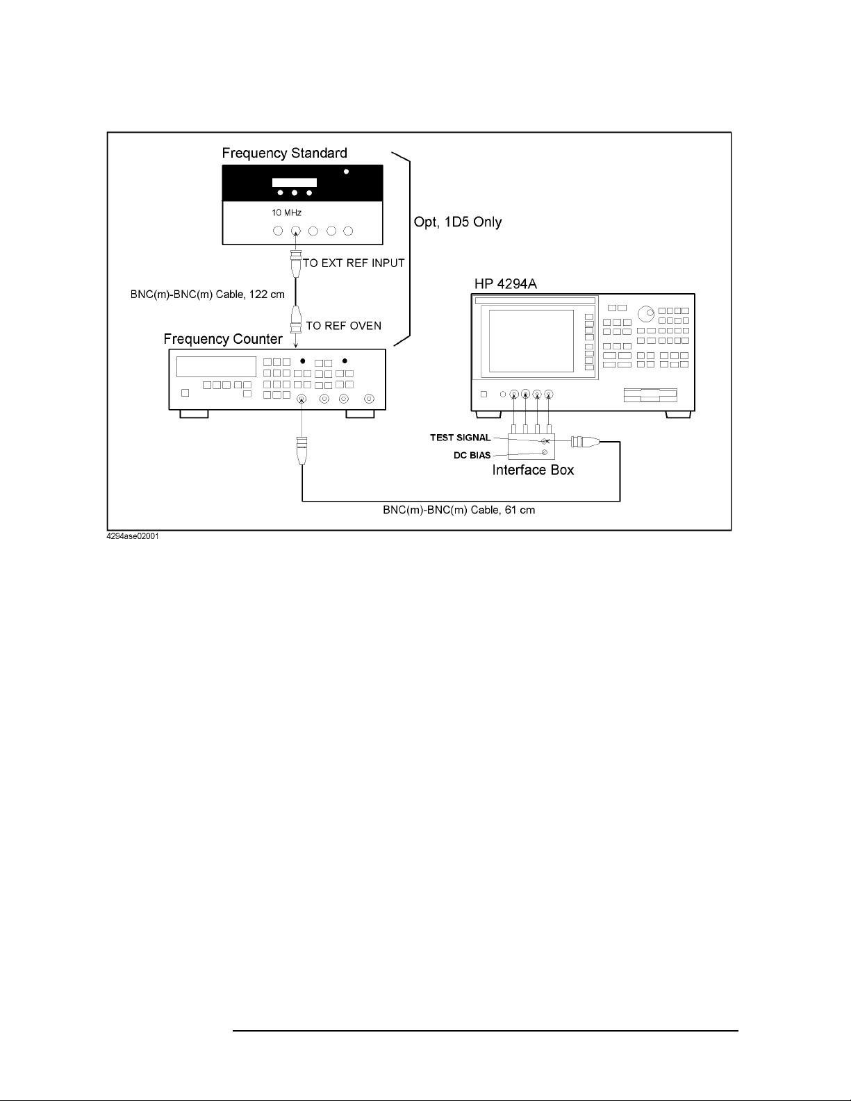
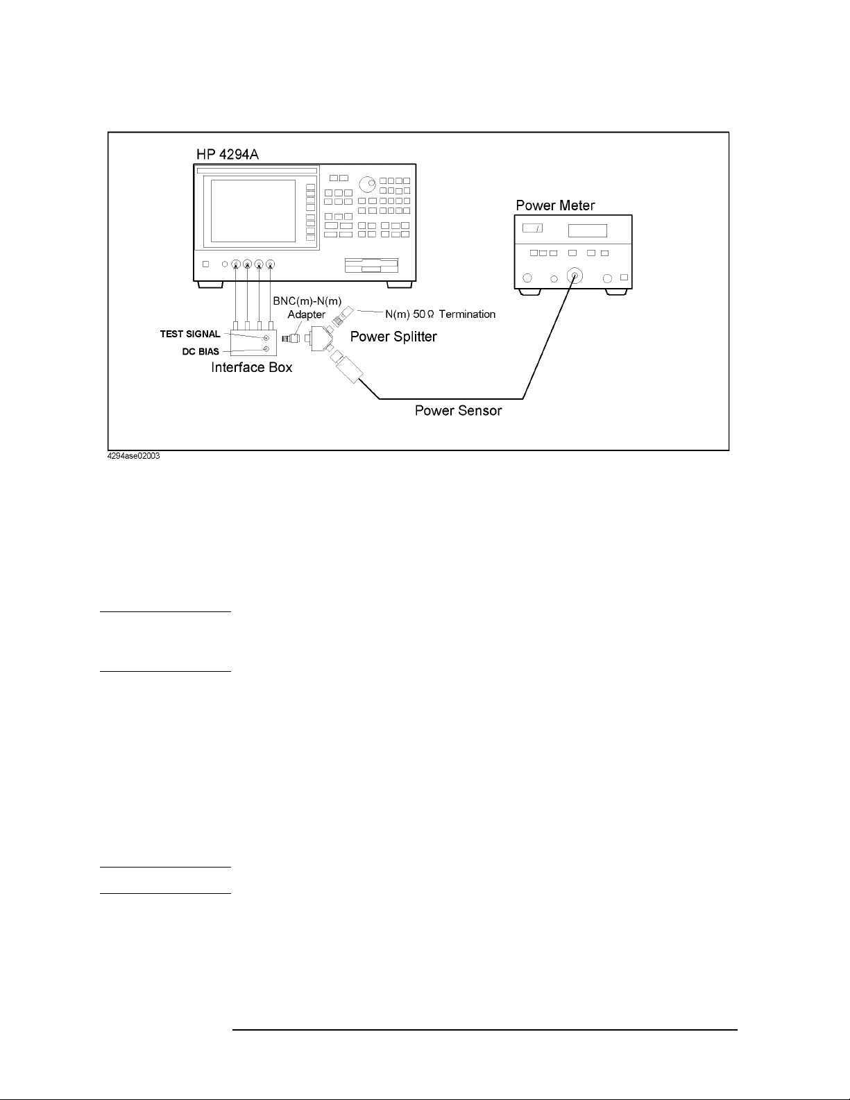
1. Connect the equipment as shown in Figure 2-2.
2 23
Page 24

Performance Test
Performance Test
Figure 2-2 OSC Level Accuracy Test Setup 1
2. Press Reset key (blue,⇒) to initialize the multimeter, then Set it as follows.
a. Press [ACV] to set the measurement mode to AC voltage.
b. Press S(blue - N Rdgs/Trig),⇓,⇓,⇓ to display SETACV.
c. Press ⇒,⇓,⇓,⇓ to display SYNC, then press [Enter]
d. Press [NPLC] - [1] - [0] - [0] - [Enter]
3. Press [Preset] to initialize the 4294A. Then set the controls as follows.
Setting Operation
Frequency Span: 0 Hz [Span] - [0] - [×1]
Center Frequency: 1 kHz [Center] - [1] - [k/m]
OSC Level: 1 V [Source] - LEVEL - [1] - [×1]
OSC Level Monitor: ON [Display] - OSC MON
Number of Points [Sweep] - NUMBER OF POINTS - [2] - [×1]
4. Press [Trigger] - Single for a single sweep measurement:
5. Record the multimeter reading and the OSC Level Monitor Reading to the calculation
sheet.
6. Calculate the monitor accuracy according to the calculation sheet, and record the
monitor accuracy into the calculation sheet.
NOTE OPEN Reading is recorded in the Step22.
24 2
Page 25

7. Confirm that the monitor accuracy is within the monitor accuracy limit.
NOTE If the monitor accuracy is beyond the limit, OSC Level Test fails.
8. Repeat from Step 4 to 7 for all OSC level and frequency setting in Table 2-1
Table 2-1 OSC Level Accuracy Test (Interface box) Settings 1
Performance Test
Performance Test
OSC Level Frequency
1.0 V 1 kHz
100 kHz
0.5 V 40 Hz
1 kHz
10 kHz
100 kHz
0.25 V 1 kHz
100 kHz
0.125 V 1 kHz
100 kHz
0.064 V 1 kHz
100 kHz
0.016 V 1 kHz
100 kHz
2. Performance Test
Accessory: Nothing, 1 MHz to 110 MHz
9. Connect the power sensor to the power meter. Calibrate the power meter for the power
sensor.
10. Set the power meter measurement mode to “Watt”
11. Disconnect the BNC(m)-BNC(m) Cable from the interface box, and connect the
equipment as shown in
2 25
Figure 2-3.
Page 26
Performance Test
Performance Test
Figure 2-3 OSC Level Accuracy Test Setup 2
12. Set the 4294A as follows.
Setting Operation
Center Frequency: 1 MHz [Center] - [1] - [M/μ]
OSC Level: 0.75 V [Source] - LEVEL - [.] - [7] - [5] - [×1]
NOTE The OSC level must be set to 0.75V because impedance mismatching occurs between the
4294A and the power sensor. The calculation sheet and the test record say the OSC level is
0.5 V.
13. Press [Trigger] - Single for a single sweep measurement:
14. Record the following values according to the calculation sheet.
a. OSC level monitor reading
b. Power meter reading
c. OSC level calculated from the power meter reading.
d. OSC level monitor accuracy.
15. Confirm that the OSC level monitor accuracy is within the monitor accuracy limit.
NOTE If the monitor accuracy is beyond the limit, OSC Level Test fails.
26 2
Page 27

Performance Test
Performance Test
16. Repeat from Step 13 to 15 for all frequency settings in Table 2-2
Table 2-2 OSC Level Accuracy Test (Interface box) Settings 2
Frequency
1 MHz
10 MHz
15 MHz
16 MHz
50 MHz
110 MHz
17. Disconnect the all test equipment from the 4294A, then connect the OPEN termination
directly to the 4294A UNKNOWN terminals.
18. Press [Source] - LEVEL - [.] - [5] - [×1] to set the 4294A OSC level to 0.5 V.
19. Press [Trigger] - Single for a single sweep measurement:
20. Read the level monitor reading for all OSC level and frequency setting in Table 2-2,
then record them to the OPEN Reading column in the calculation sheet.
21. Press [Trigger] - Single for a single sweep measurement:
22. Read the level monitor reading for all OSC level and frequency setting in Table 2-1,
then record them to the OPEN Reading column in the calculation sheet.
23. Calculate the test results according to the calculation sheet, then record them to the test
record.
With 42942A Terminal Adapter
24. Disconnect the all test equipment from the 4294A, then connect the equipment as
shown in
Figure 2-4
2. Performance Test
2 27
Page 28

Performance Test
Performance Test
Figure 2-4 42942A Setup
25. Setup the 42942A as follows.
a. Press [Cal],Adapter,7mm 42942A,SETUP.
b. Connect the OPEN termination furnished with the 42942A to the 7mm connector.
c. Press PHASE COMP to measure the phase compensation data.
d. Press OPEN to measure the open compensation data.
e. Connect the SHORT termination furnished with the 42942A instead of the OPEN
termination.
f. Press SHORT to measure the short compensation data.
g. Connect the 50 Ω termination furnished with the 42942A instead of the SHORT
termination.
h. Press LOAD to measure the load compensation data.
i. Press done to activate the measured compensation data.
26. Connect the instruments as shown in Figure 2-5.
28 2
Page 29

Figure 2-5 OSC Level Accuracy Test Setup 3
Performance Test
Performance Test
2. Performance Test
27. Set the 4294A as follows.
Setting Operation
Center Frequency: 1 MHz [Center] - [1] - [M/m]
OSC Level: 0.75 V [Source] - LEVEL - [.] - [7] - [5] - [×1]
NOTE The OSC level must be set to 0.75V because a impedance mismatch occurs between the
4294A and the power sensor.
28. Press [Trigger] - Single for a single sweep measurement:
29. Record the following values according to the calculation sheet.
a. OSC level monitor reading
b. Power meter reading
c. OSC level calculated from the power meter reading.
d. OSC level monitor accuracy.
30. Confirm that the monitor accuracy is within the monitor accuracy limit.
NOTE If the monitor accuracy is beyond the limit, OSC Level Test fails.
2 29
Page 30

Performance Test
Performance Test
31. Repeat from Step 28 to 30 for all frequency settings in Table 2-3
Table 2-3 OSC Level Accuracy Test (Interface box) Settings 3
Frequency
1 MHz
10 MHz
15 MHz
16 MHz
50 MHz
110 MHz
32. Disconnect the test equipment from the 7mm connect, then connect the OPEN
termination to the 7mm connector.
33. Press [Source] - LEVEL - [.] - [5] - [×1] to set the 4294A OSC level to 0.5 V.
34. Press [Trigger] - Single for a single sweep measurement:
35. Read the level monitor reading for all OSC level and frequency setting in Table 2-3,
then record them to the calculation sheet.
36. Calculate the test results according to the calculation sheet, then record them to the test
record.
30 2
Page 31

Performance Test
Performance Test
DC Bias Monitor Accuracy Test
This test checks the accuracy of the DC bias monitor.
Specification
Voltage Monitor Accuracy: ±[0.2 % + ( 5 + 0.3 × |Imon(mA)| ) mV]
at (23 ± 5) ºC
Current Monitor Accuracy: ±[1 % + ( 0.5 + |Vmon(mV)| / 10000) mA]
at (23 ± 5) ºC
Test Equipment
Description Recommended Model
Multimeter 3458A
61 cm BNC(m)-BNC(m) Cable p/n 8120-1839
Dual Banana-BNC(f) Adapter p/n 1251-2277
4TP-BNC Interface Box p/n 04294-61002
Procedure
1. Connect the equipment as shown in Figure 2-6
Figure 2-6 DC Bias Monitor Accuracy Test (voltage) Setup
2. Performance Test
2. Press Reset key (blue - ⇒) to initialize the multimeter, then Set it as follows.
a. Press [DCV] to set the measurement mode to DC voltage.
2 31
Page 32

Performance Test
Performance Test
b. Press [NPLC] - [1] - [0] - [0] - [Enter].
3. Press [Preset] to initialize the 4294A, then set it as follows.
Setting Operation
Adapter: None [Cal] - ADAPTER - NONE
OSC Level: 0 V
*1
[Source] - [0] - [×1]
DC Bias: On [Source] - BIAS MENU - BIAS
DC Bias Mode: Voltage [Source] - BIAS MENU - MODE - VOLT
DC Bias Monitor: Voltage [Display] - BIAS MON - VOLT
DC Bias Level: 0 V [Source] - BIAS MENU - VOLTAGE LEVEL - [0] -
[×1]
*1.OSC level is set to 5 mV automatically.
4. Press [Trigger] - Single for a single sweep measurement:
5. Record the multimeter reading and the DC Bias monitor reading on the calculation
sheet.
6. Calculate the result according to the calculation sheet, then record it on the
performance test record.
7. Perform Step 5 and 6 for all setting in Table 2-4
Table 2-4 DC Bias Monitor Accuracy Test (voltage) Setting
Bias Level
0 V
25 V
40 V
–25 V
–40 V
8. Connect the equipment as shown in Figure 2-7
32 2
Page 33

Figure 2-7 DC Bias Monitor Accuracy Test (current) Setup
Performance Test
Performance Test
2. Performance Test
9. Press Reset key (blue - ⇒) to initialize the multimeter, then Set it as follows.
a. Press [DCI] to set the measurement mode to DC current.
b. Press [NPLC] - [1] - [0] - [0] - [Enter].
10. Press [Preset] to initialize the 4294A, then set it as follows.
Setting Operation
OSC Level: 0 V
*1
[Source] - [0] - [×1]
DC Bias Mode: Voltage [Source] - BIAS MENU - MODE - VOLT
DC Bias Monitor: Current [Display] - BIAS MON - CURRENT
DC Bias Level: 0 V [Source] - BIAS MENU - VOLTAGE LEVEL - [0] -
[×1]
*1.OSC level is set to 5 mV automatically.
11. Perform as follows to adjust the actual 4294A OSC output level to the test point.
a. Set the DC Bias level to “DC Bias Setting 1” column in the calculation sheet.
b. Press [Trigger] - Single for a single sweep measurement:
c. Record the multimeter reading to “Multimeter reading 1” column in the calculation
sheet.
d. Calculate “DC Bias Setting 2” according to the calculation sheet, then set the DC
Bias level to it.
NOTE When test point is “0 mA”, Step b and c is not required.
2 33
Page 34

Performance Test
Performance Test
12. Press [Trigger] - Single for a single sweep measurement.
13. Record the multimeter reading and the DC Bias monitor reading, then record them on
the calculation sheet.
14. Calculate the result according to the calculation sheet, then record it on the
performance test record.
15. Perform Step 11 and 14 for all setting in Table 2-5
Table 2-5 DC Bias Monitor Accuracy Test (current) Setting
Bias Level
0 mA
20 mA
100 mA
–20 mA
–100 mA
34 2
Page 35

Performance Test
Performance Test
DC Bias Level Accuracy Test
This test checks the accuracy of the DC bias level at several level.
Specification
Voltage Monitor Accuracy: ±[0.1 % + (5 + 30 × |Imon(mA)| ) mV]
at (23 ± 5) ºC
Current Monitor Accuracy: ±[2 % + ( 0.2 + |Vmon(mV)| / 20) mA]
at (23 ± 5) ºC
Test Equipment
Description Recommended Model
Multimeter 3458A
SHORT Termination 42091A
61 cm BNC(m)-BNC(m) Cable p/n 8120-1839
2. Performance Test
Dual Banana-BNC(f) Adapter p/n 1251-2277
4TP-BNC Interface Box p/n 04294-65002
Procedure
NOTE Calibration factor must be calculated in DC Bias Monitor Accuracy Test before this test is
performed.
1. Connect the equipment as shown in Figure 2-8
2 35
Page 36

Performance Test
Performance Test
Figure 2-8 DC Bias Level Accuracy Test (voltage) Setup
2. Press Reset key (blue - ⇒) to initialize the multimeter, then Set it as follows.
a. Press [DCV] to set the measurement mode to DC voltage.
b. Press [NPLC] - [1] - [0] - [0].
3. Press [Preset] to initialize the 4294A, then set it as follows.
Setting Operation
Adapter: None [Cal] - ADAPTER - NONE
OSC Level: 0 V [Source] - [0] - [×1]
DC Bias: On [Source] - BIAS MENU - BIAS
DC Bias Mode: Voltage [Source] - BIAS MENU - MODE - VOLT
DC Bias Monitor: Voltage [Display] - BIAS MON - VOLT
DC Bias Level: 0 V [Source] - BIAS MENU - VOLTAGE LEVEL - [0] -
[×1]
4. Press [Trigger] - Single for a single sweep measurement:
5. Record the multimeter reading on the calculation sheet.
6. Calculate the result according to the calculation sheet, then record it on the
performance test record.
7. Perform Step 5 and 6 for all setting in Table 2-6.
36 2
Page 37

Performance Test
Performance Test
Table 2-6 DC Bias Monitor Accuracy Test (voltage) Setting
Bias Level
0 V
25 V
40 V
–25 V
–40 V
8. Disconnect the all test equipment from the 4294A, then connect the SHORT
Termination to the 4294A UNKNOWN Terminal.
9. Press [Preset] to initialize the 4294A, then set it as follows.
Setting Operation
OSC Level: 0 V [Source] - [0] - [×1]
2. Performance Test
DC Bias Mode: Current [Source] - BIAS MENU - MODE - CURRENT
DC Bias Monitor: Current [Display] - BIAS MON - CURRENT
DC Bias Level: 0 A [Source] - BIAS MENU - CURRENT LEVEL - [0] -
[×1]
10. Press [Trigger] - Single for a single sweep measurement:
11. Record the DC Bias Monitor reading to “DC Bias Reading 1” on the calculation sheet.
12. Calculate the result according to the calculation sheet, then record it on the calculation
sheet.
13. Perform Step 11 and 12 for all setting in Table 2-7
Table 2-7 DC Bias Monitor Accuracy Test (current) Setting
Bias Level
0 mA
20 mA
100 mA
–20 mA
–100 mA
2 37
Page 38

Performance Test
Performance Test
Measurement Accuracy Test
This test checks the DC bias level of the stimulus signal at several frequencies from 40 Hz
to 110 MHz.
Specification
Measurement Accuracy: Basic Accuracy: 0.08%
See the Specifications on Operation Manual for details.
Test Equipment
Description Recommended Model
Standard Capacitor Set 16380A
Standard Capacitor Set 16380C
Standard Resistor Set 42030A
Terminal Adapter 42942A
Performance Test Kit 16190A
100 Ω Resistor
1m Test Leads 16048G
2m Test Leads 16048H
*1.A attachment to the 4294A
Procedure
1. Record the 16380A, 16380C, 42030A, 16190A calibration values on the calculation
sheet.
2. Press [Preset] to initialize the 4294A.
3. Press [Cal], then confirm that Adapter is set to NONE. If it is not set to NONE, Press
ADAPTER - NONE.
4. Connect the OPEN Termination to the 4294A UNKNOWN Terminal as shown in
Figure 2-9.
*1
p/n 04294-61001
38 2
Page 39

Figure 2-9 Measurement Accuracy Test Setup (Accessory: None)
Performance Test
Performance Test
2. Performance Test
5. Press [Cal] - FIXTURE COMPEN - OPEN
6. Connect the SHORT termination instead of the OPEN termination
7. Press [Cal] - FIXTURE COMPEN - SHORT
8. Press [Meas] - more 1/3 - Cp-D to set the 4294A Measurement mode to Cp-D.
9. Create the sweep list shown in Figure 2-10. Segment 1 is added by the following
procedure.
a. Press [Sweep] - EDIT LIST - [ADD] to add a segment to the sweep list.
b. Edit the segment as follows.
Setting Operation
Start Frequency: 40 Hz START - [4] - [0] - [×1]
Stop Frequency: 1 kHz STOP - [1] - [k/m]
Number of Point: 2 NUMBER OF POINT - [2]
OSC level: 500 mV more 1/3 - OSC LEVEL - [5] - [0] - [0] - [k/m]
Bandwidth more 2/3 - BANDWIDTH - 5 PRECISE
NOTE Press the START or STOP Softkey. Do NOT press the front panel key printed “Start” or
“Stop”.
2 39
Page 40

Performance Test
Performance Test
Figure 2-10 Sweep List for Measurement Accuracy Test
c. Press done.
10. Press done to save the sweep list menu.
11. Press TYPE - LIST to set the sweep type to the list sweep.
12. Connect the 1 pF standard capacitor to the 4294A UNKNOWN Terminal as shown in
Figure 2-9 on page 39.
13. Press [Trigger] - SINGLE to make a measurement.
14. Press [Copy] - SELECT CONTENTS - LIST VALUE to show the list as shown in Figure
2-11.
40 2
Page 41

Figure 2-11 Measurement Value List
Performance Test
Performance Test
2. Performance Test
15. Record the 4294A reading on the calculation sheet for all setting in Table 2-8, then
Calculate the test result.
2 41
Page 42

Performance Test
Performance Test
Table 2-8 Measurement Accuracy Test(Accessory: None, Standard
Capacitor) Setting
Standard
Capacitor
1 pF 0.5 V 1 MHz
10 pF 0.5 V 1 kHz
100 pF 0.5 V 1 kHz
OSC Level Frequency
3 MHz
1 MHz
3 MHz
10 MHz
0.1 V 1 kHz
100 kHz
1 MHz
3 MHz
10 MHz
0.1 V 1 kHz
100 kHz
1 MHz
3 MHz
10 MHz
1000 pF 0.5 V 1 kHz
10 kHz
100 kHz
0.1 V 1 kHz
0.01 μF
0.1 μF
1 μF
0.5 V 120 Hz
1 kHz
10 kHz
0.1 V 1 kHz
0.5 V 120 Hz
1 kHz
10 kHz
0.1 V 1 kHz
0.5 V 120 Hz
1 kHz
0.1 V 1 kHz
42 2
Page 43

Performance Test
Performance Test
16. Connect the 10 Ω standard resistor to the 4294A UNKNOWN Terminal as shown in
Figure 2-9 on page 39.
17. Press [Meas] - R-X to set the measurement mode to R-X.
18. Press [Trigger] - SINGLE to make a measurement.
19. Record the 4294A reading on the calculation sheet for all setting in Table 2-9, then
calculate the test result.
Table 2-9 Measurement Accuracy Test(Accesory:None, Standard
Resister) Setting
2. Performance Test
Standard
Capacitor
10 Ω 0.5 V 1 kHz
1 Ω 0.5 V 1 kHz
100 mΩ 0.5 V 1 kHz
10 mΩ 0.5 V 1 kHz
20. Disconnect all the equipment from the 4294A, then connect the equipment as shown in
Figure 2-12.
Figure 2-12 Measurement Accuracy Test(Accessory: 42942A Terminal Adapter)
OSC Level Frequency
0.1 V 1 kHz
0.1 V 1 kHz
0.1 V 1 kHz
0.1 V 1 kHz
2 43
Page 44

Performance Test
Performance Test
21. Press [Cal] - Adapter - 7mm 42942A to set the adapter to the 42942A.
22. Setup the 4294A as follows.
NOTE If Setup is completed in OSC level accuracy test, this operation is not required.
a. Press SETUP.
b. Connect the OPEN termination furnished with the 42942A to the 7mm connector.
c. Press PHASE COMP to measure the phase compensation data.
d. Press OPEN to measure the open compensation data.
e. Connect the SHORT termination furnished with the 42942A instead of the OPEN
termination.
f. Press SHORT to measure the short compensation data.
g. Connect the 50 Ω termination furnished with the 42942A instead of the SHORT
termination.
h. Press LOAD to measure the load compensation data.
i. Press done to activate the measured compensation data.
23. Press [Meas] - |Z|-θ to set the measurement mode.
24. Press [B] - [Format] - PHASE UNIT to set the phase display unit to radian.
25. Connect the 50 Ω Termination furnished with the 16190A to the 7mm connector.
26. Press [Trigger] - Single to make a measurement.
27. Record the 4294A reading on the calculation sheet for all setting in Table 2-10, then
calculate the test result.
Table 2-10 Measurement Accuracy Test (Accessory: 42942A
Terminal Adapter, 50 Ω) Setting
OSC Level Frequency
0.5 V 1 kHz
1 MHz
10 MHz
100 MHz
28. Connect the 10 cm airline and the OPEN termination to the 7mm connector as
follows.(refer to
a. Fully retract the threads on the test head 7mm connector. Then insert the marked
side tip of the airline center conductor into the connector center conductor.
Figure 2-13)
b. Gently cover the airline center conductor with the airline outer conductor, with the
Agilent logo side down. (To prevent damage, do not let the center conductor scrape
the edge of the outer conductor.) Mate the outer conductors. Then tie the connection
by the 136 N·cm. (A 1/2 inch open end wrench may be necessary to hold the airline
stationary)
44 2
Page 45

c. Gently inserts the airline center conductor into the open termination center
conductor. Mate the outer conductors. Then tie the connection by the 136 N·cm
torque.
Figure 2-13 10cm Airline with OPEN Measurement Test Setup
Performance Test
Performance Test
2. Performance Test
29. Press [Trigger] - Single to make a measurement.
30. Record the 4294A reading on the calculation sheet for all setting in Table 2-11, then
calculate the test result.
Table 2-11 Measurement Accuracy Test (Accessory: 42942A
Terminal Adapter, SHORT or OPEN Termination)
Setting
OSC Level Frequency
0.5 V 1 MHz
10 MHz
100 MHz
31. Connect the 10cm airline and SHORT termination to the 7mm connector as follows.
(refer to
a. Remove the OPEN termination from the airline.
b. Gently inserts the airline center conductor into the short termination center
Figure 2-14)
conductor. Mate the outer conductors. Then tie the connection by the 136 N·cm
2 45
Page 46

Performance Test
Performance Test
torque. (A 1/2 inch open end wrench may be necessary to hold the airline
stationary.)
Figure 2-14 10 cm Airline with SHORT Measurement Test Setup
32. Press [Trigger] - Single to make a measurement.
33. Record the 4294A reading on the calculation sheet for all setting in Table 2-11 on page
45, then calculate the test result.
34. Disconnect all the equipment from the 4294A, then perform the setup as follows
a. Connect the 1m Test Leads to the 4294A UNKNOWN Terminal.
b. Press [Cal] - ADAPTER - 4TP 1M - SETUP.
c. Connect the 100 Ω Resistor to 1m Test Leads as shown in Figure 2-15.
46 2
Page 47

Figure 2-15 Connection for phase compensation
Performance Test
Performance Test
2. Performance Test
d. Press PHASE COMP to measure the phase compensation data.
e. Connect the 100 Ω Resistor’s all terminals to the test leads as shown in Figure 2-16.
Figure 2-16 Connection for load compensation
f. Press LOAD to measure the load compensation data.
g. Press done to activate the compensation data.
2 47
Page 48

Performance Test
Performance Test
Figure 2-17 Measurement Accuracy Test Setup (Accessory: 1m Test Leads)
35. Connect the OPEN Termination as shown in Figure 2-17.
36. Press [Cal] - FIXTURE COMPEN - OPEN.
37. Connect the SHORT termination instead of the OPEN termination.
38. Press [Cal] - FIXTURE COMPEN - SHORT.
39. Connect the 10 pF standard capacitor to the 4294A UNKNOWN Terminal as shown in
Figure 2-17.
40. Press [Meas] - more 1/3 - Cp-D to set the 4294A Measurement mode to Cp-D.
41. Press [Trigger] - Single to make a measurement.
42. Record the 4294A reading on the calculation sheet for all setting in Table 2-12, then
Calculate the test result.
48 2
Page 49

Performance Test
Performance Test
Table 2-12 Measurement Accuracy Test(Accesory:1m Test Leads,
Standard Capacitor) Setting
Standard
Capacitor
10 pF 0.5 V 1 kHz
100 pF 0.5 V 1 kHz
43. Connect the 1 Ω standard resistor as shown in Figure 2-17.
44. Press [Meas] - R-X to set the measurement mode to R-X.
45. Press [Trigger] - Single to make a measurement.
46. Record the 4294A reading on the calculation sheet for all setting in Table 2-13, then
Calculate the test result.
OSC Level Frequency
1 MHz
3 MHz
10 MHz
100 kHz
1 MHz
3 MHz
10 MHz
Table 2-13 Measurement Accuracy Test(Accesory:1m Test Leads,
Standard Resistor) Setting
2. Performance Test
Standard
Capacitor
1 Ω 0.5 V 1 kHz
100 mΩ 0.5 V 1 kHz
47. Disconnect all the equipment from the 4294A, then perform the setup as follows.
a. Connect the 2m Test Leads to the 4294A UNKNOWN Terminal.
b. Press [Cal] - ADAPTER - 4TP 2M - SETUP.
c. Connect the 100 Ω Resistor to 2m Test Leads as shown in Figure 2-15 on page 47.
d. Press PHASE COMP to measure the phase compensation data.
e. Connect the 100 Ω Resistor’s all terminals to the test leads as shown in Figure 2-16
on page 47.
f. Press LOAD to measure the load compensation data.
g. Press done to activate the compensation data.
48. Connect the Standard capacitor as shown in Figure 2-18.
2 49
OSC Level Frequency
Page 50

Performance Test
Performance Test
Figure 2-18 Measurement Accuracy Test Setup (Accessory: 2m Test Leads)
49. Press [Cal] - FIXTURE COMPEN - OPEN
50. Connect the SHORT termination instead of the OPEN termination
51. Press [Cal] - FIXTURE COMPEN - SHORT
52. Connect the 10 pF standard capacitor to the 4294A UNKNOWN Terminal as shown in
Figure 2-18.
53. Press [Meas] - more 1/3 - Cp-D to set the 4294A Measurement mode to Cp-D.
54. Press [Trigger] - Single to make a measurement.
55. Record the 4294A reading on the calculation sheet for all setting in Table 2-14, then
Calculate the test result.
50 2
Page 51

Performance Test
Performance Test
Table 2-14 Measurement Accuracy Test(Accesory:2m Test Leads,
Standard Capacitor) Setting
Standard
Capacitor
10 pF 0.5 V 1 kHz
100 pF 0.5 V 1 kHz
56. Connect the Standard resistor as shown in Figure 2-18.
57. Press [Meas] - R-X to set the measurement mode to R-X.
58. Press [Trigger] - Single to make a measurement.
59. Record the 4294A reading on the calculation sheet for all setting in Table 2-15, then
Calculate the test result.
OSC Level Frequency
1 MHz
3 MHz
10 MHz
100 kHz
1 MHz
3 MHz
10 MHz
Table 2-15 Measurement Accuracy Test(Accesory:2m Test Leads,
Standard Resistor) Setting
2. Performance Test
Standard
Capacitor
1 Ω 0.5 V 1 kHz
100 mΩ 0.5 V 1 kHz
OSC Level Frequency
2 51
Page 52

Performance Test
Calculation Sheet
Calculation Sheet
OSC Level Accuracy Test
OSC Level Accuracy(Accessory: Nothing, 40 Hz to 100 kHz)
OSC
Level
[a]
1.0 V 1 kHz V V V ± 0.1001 V V mV
0.5 V 40 Hz V V V ± 0.0500 V V mV
0.25 V 1 kHz V V V ± 0.0250 V V mV
0.125 V 1 kHz V V V ± 0.0125 V V mV
0.064 V 1 kHz V V V ± 0.0064 V V mV
0.016 V 1 kHz V V V ± 0.0016 V V mV
Freq. Monitor
Reading
[b]
100 kHz V V V ± 0.1001 V V mV
1 kHz V V V ± 0.0500 V V mV
10 kHz V V V ± 0.0500 V V mV
100 kHz V V V ± 0.0500 V V mV
100 kHz V V V ± 0.0250 V V mV
100 kHz V V V ± 0.0125 V V mV
100 kHz V V V ± 0.0064 V V mV
Multimeter
Reading
[b]
Monitor
Accuracy
[b–c]
Monitor
Accuracy
Limit
OPEN
Reading
[d]
Test Result
[d×c/b–a]
100 kHz V V V ± 0.0016 V V mV
52 2
Page 53

OSC Level Accuracy (Accessory: Nothing, 1 MHz to 110 MHz)
Performance Test
Calculation Sheet
OSC
Level
[a]
0.5 V 1 MHz V W V V ± 0.0904 V V mV
Freq. Monitor
Reading
[b]
10 MHz V W V V ± 0.0938 V V mV
15 MHz V W V V ± 0.0956 V V mV
16 MHz V W V V ± 0.0960 V V mV
50 MHz V W V V ± 0.1088 V V mV
110 MHz V W V V ± 0.1313 V V mV
Power
Meter
Reading
[c]
Calculated
OSC level
[d]
250 c×=
Monitor
Accuracy
[b–d]
Monitor
Accuracy
Limit
OPEN
Reading
[e]
Test Re s u l t
[e×d/b–a]
OSC Level Accuracy (with 42942A Terminal Adapter)
OSC
Level
[a]
0.5 V 1 MHz V W V V ± 0.0904 V V mV
Freq. Monitor
Reading
[b]
Power
Meter
Reading
[c]
Calculated
OSC level
[d]
250 c×=
Monitor
Accuracy
[b–d]
Monitor
Accuracy
Limit
OPEN
Reading
[e]
Test Re s u l t
[e×d/b–a]
2. Performance Test
10 MHz V W V V ± 0.0938 V V mV
15 MHz V W V V ± 0.0956 V V mV
16 MHz V W V V ± 0.0960 V V mV
50 MHz V W V V ± 0.1088 V V mV
110 MHz V W V V ± 0.1313 V V mV
2 53
Page 54

Performance Test
Calculation Sheet
DC Bias Monitor Accuracy Test
DC Bias Monitor Accuracy Test (voltage)
Bias Level Monitor Reading
[a]
0 V V V V
25 V V V V
40 V V V V
–25 V V V V
–40 V V V V
DC Bias Monitor Accuracy
Bias Level
[a]
0 mA 0 V –––––––––– –––––––––– mA mA mA
20 mA 0.5 V mA V mA mA mA
100 mA 2.5 V mA V mA mA mA
–20 mA –0.5 V mA V mA mA mA
DC Bias
Setting 1 [b]
Multimeter
Reading 1
[c]
DC Bias
Setting 2
[d]=a×b/c
Multimeter
Reading [b]
Monitor
Reading [e]
Test Result
[b–a]
Multimeter
Reading 2
[f]
Test R es ul t
[e–f]
–100 mA –2.5 V mA V mA mA mA
54 2
Page 55

DC Bias Level Accuracy Test
DC Bias Level Accuracy Test (voltage)
Performance Test
Calculation Sheet
Bias Level [a] Multimeter
Reading [b]
Test Result
Equation [b–a]
0 V V V
25 V V V
40 V V V
–25 V V V
–40 V V V
DC Bias Level Accuracy Test (current)
Bias Level [a]
Cal Factor
*1
[b]
Monitor Reading
[c]
Test Result
[b×c–a]
0 mA mA mA
20 mA mA mA
100 mA mA mA
–20 mA mA mA
–100 mA mA mA
2. Performance Test
*1.Calculate f/e in DC Bias Monitor Accuracy Test Calculation Sheet
2 55
Page 56

Performance Test
Calculation Sheet
Measurement Accuracy Test
Standard Calibration Values (16380A/C,42030A)
Stand ard Frequency Parameter Calibration Value Reference
Designation
1 pF 1 MHz Cp pF CV1
D CV2
3 MHz Cp pF CV3
D CV4
10 pF 1 kHz Cp pF CV5
D CV6
1 MHz Cp pF CV7
D CV8
3 MHz Cp pF CV9
D CV10
10 MHz Cp pF CV11
D CV12
100 pF 1 kHz Cp pF CV13
D CV14
1 MHz Cp pF CV15
D CV16
3 MHz Cp pF CV17
D CV18
10 MHz Cp pF CV19
D CV20
1000 pF 1 kHz Cp pF CV21
D CV22
56 2
Page 57

Performance Test
Calculation Sheet
Standard Frequency Parameter Calibration Value Reference
Designation
0.01 μF 120 Hz Cp nF CV23
D CV24
1 kHz Cp nF CV25
D CV26
10 kHz Cp nF CV27
D CV28
0.1 μF 120 Hz Cp nF CV29
D CV30
1 kHz Cp nF CV31
D CV32
10 kHz Cp nF CV33
D CV34
1 μF 120 Hz Cp μF CV35
D CV36
1 kHz Cp μF CV37
D CV38
10 Ω DC R Ω CV39
1 Ω DC R Ω CV40
2. Performance Test
100 mΩ DC R mΩ CV41
10 mΩ DC R mΩ CV42
2 57
Page 58
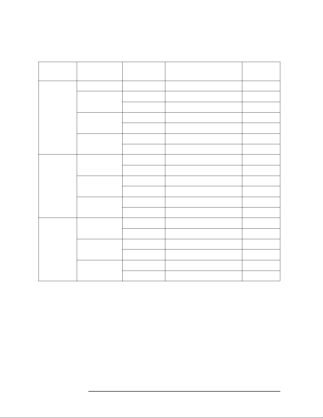
Performance Test
Calculation Sheet
Standard Calibration Values (16190A)
Table 2-16 Standard Calibration Value
Stand ard Frequency Parameter Calibration Value Reference
Designation
50 Ω DC R Ω CV43
1 MHz |Z| Ω CV44
θ mrad CV45
10 MHz |Z| Ω CV46
θ mrad CV47
100 MHz |Z| Ω CV48
θ mrad CV49
Airline with 1 MHz |Z| Ω CV50
OPEN θ rad CV51
10 MHz |Z| Ω CV52
θ rad CV53
100 MHz |Z| Ω CV54
θ rad CV55
Airline with 1 MHz |Z| Ω CV56
SHORT θ rad CV57
10 MHz |Z| Ω CV58
θ rad CV59
100 MHz |Z| Ω CV60
θ rad CV61
58 2
Page 59

Measurement Accuracy Test
Accessory: Nothing
Standard: 1 pF
Performance Test
Calculation Sheet
OSC Level Frequency Parameter 4294A reading
[a]
0.5 V 1 MHz Cp pF a – CV1
D a – CV2
3 MHz Cp pF a – CV3
D a – CV4
Accessory: Nothing
Standard: 10 pF
OSC Level Frequency Parameter 4294A reading
[a]
0.5 V 1 kHz Cp pF a – CV5
D a – CV6
1 MHz Cp pF a – CV7
D a – CV8
3 MHz Cp pF a – CV9
Test Result
Equation
Test Result
Equation
2. Performance Test
D a – CV10
10 MHz Cp pF a – CV11
D a – CV12
0.1 V 1 kHz Cp pF a – CV5
D a – CV6
2 59
Page 60

Performance Test
Calculation Sheet
Accessory: Nothing
Standard: 100 pF
OSC Level Frequency Parameter 4294A reading
[a]
0.5 V 1 kHz Cp pF a – CV13
D a – CV14
100 kHz Cp pF a – CV13
D a – CV14
1 MHz Cp pF a – CV15
D a – CV16
3 MHz Cp pF a – CV17
D a – CV18
10 MHz Cp pF a – CV19
D a – CV20
0.1 V 1 kHz Cp pF a – CV13
D a – CV14
100 kHz Cp pF a – CV13
Test Result
Equation
D a – CV14
1 MHz Cp pF a – CV15
D a – CV16
3 MHz Cp pF a – CV17
D a – CV18
10 MHz Cp pF a – CV19
D a – CV20
60 2
Page 61

Accessory: Nothing
Standard: 1000 pF
Performance Test
Calculation Sheet
OSC Level Frequency Parameter 4294A reading
[a]
0.5 V 1 kHz Cp pF a – CV21
D a – CV22
10 kHz Cp pF a – CV21
D a – CV22
100 kHz Cp pF a – CV21
D a – CV22
0.1 V 1 kHz Cp pF a – CV21
D a – CV22
Accessory: Nothing
Standard: 0.01 μF
OSC Level Frequency Parameter 4294A reading
[a]
0.5 V 120 Hz Cp nF a – CV23
Test Result
Equation
Test Result
Equation
2. Performance Test
D a – CV24
1 kHz Cp nF a – CV25
D a – CV26
10 kHz Cp nF a – CV27
D a – CV28
0.1 V 1 kHz Cp nF a – CV25
D a – CV26
2 61
Page 62

Performance Test
Calculation Sheet
Accessory: Nothing
Standard: 0.1 μF
OSC Level Frequency Parameter 4294A reading
[a]
0.5 V 120 Hz Cp nF a – CV29
D a – CV30
1 kHz Cp nF a – CV31
D a – CV32
10 kHz Cp nF a – CV33
D a – CV34
0.1 V 1 kHz Cp nF a – CV31
D a – CV32
Accessory: Nothing
Standard: 1 μF
OSC Level Frequency Parameter 4294A reading
[a]
0.5 V 120 Hz Cp μF a – CV35
Test Result
Equation
Test Result
Equation
D a – CV36
1 kHz Cp μF a – CV37
D a – CV38
0.1 V 1 kHz Cp μF a – CV35
D a – CV36
Accessory: Nothing
Standard: 10 Ω
OSC Level Frequency Parameter 4294A reading
[a]
0.5 V 1 kHz R Ω a – CV39
0.1 V 1 kHz R Ω a – CV39
Test Result
Equation
62 2
Page 63

Accessory: Nothing
Standard: 1 Ω
Performance Test
Calculation Sheet
OSC Level Frequency Parameter 4294A reading
[a]
0.5 V 1 kHz R Ω a – CV40
0.1 V 1 kHz R Ω a – CV40
Accessory: Nothing
Standard: 100 mΩ
OSC Level Frequency Parameter 4294A reading
[a]
0.5 V 1 kHz R mΩ a – CV41
0.1 V 1 kHz R mΩ a – CV41
Accessory: Nothing
Standard: 10 mΩ
OSC Level Frequency Parameter 4294A reading
[a]
0.5 V 1 kHz R mΩ a – CV42
Test Result
Equation
Test Result
Equation
Test Result
Equation
2. Performance Test
0.1 V 1 kHz R mΩ a – CV42
Accessory: 42942A Terminal Adapter
Standard: 50 Ω
OSC Level Frequency Parameter 4294A reading
[a]
0.5 V 1 kHz |Z| Ω a – CV43
θ rad a
1 MHz |Z| Ω a – CV44
θ rad a – CV45
10 MHz |Z| Ω a – CV46
θ rad a – CV47
100 MHz |Z| Ω a – CV48
θ rad a – CV49
Test Result
Equation
2 63
Page 64

Performance Test
Calculation Sheet
Accessory: 42942A Terminal Adapter
Standard: OPEN
OSC Level Frequency Parameter 4294A reading
[a]
0.5 V 1 MHz |Z| Ω a – CV50
θ rad a – CV51
10 MHz |Z| Ω a – CV52
θ rad a – CV53
100 MHz |Z| Ω a – CV54
θ rad a – CV55
Accessory: 42942A Terminal Adapter
Standard: SHORT
OSC Level Frequency Parameter 4294A reading
[a]
0.5 V 1 MHz |Z| Ω a – CV44
θ rad a – CV45
10 MHz |Z| Ω a – CV46
Test Result
Equation
Test Result
Equation
θ rad a – CV47
100 MHz |Z| Ω a – CV48
θ rad a – CV49
Accessory: 1m Test Leads
Standard: 10 pF
OSC Level Frequency Parameter 4294A reading
[a]
0.5 V 1 kHz Cp pF a – CV5
D a – CV6
1 MHz Cp pF a – CV7
D a – CV8
3 MHz Cp pF a – CV9
D a – CV10
10 MHz Cp pF a – CV11
D a – CV12
Test Result
Equation
64 2
Page 65

Accessory: 1m Test Leads
Standard: 100 pF
Performance Test
Calculation Sheet
OSC Level Frequency Parameter 4294A reading
[a]
0.5 V 1 kHz Cp pF a – CV13
D a – CV14
100 kHz Cp pF a – CV13
D a – CV14
1 MHz Cp pF a – CV15
D a – CV16
3 MHz Cp pF a – CV17
D a – CV18
10 MHz Cp pF a – CV19
D a – CV20
Accessory: 1m Test Leads
Standard: 1 Ω
OSC Level Frequency Parameter 4294A reading
[a]
Test Result
Equation
Test Result
Equation
2. Performance Test
0.5 V 1 kHz R Ω a – CV40
Accessory: 1m Test Leads
Standard: 100 mΩ
OSC Level Frequency Parameter 4294A reading
[a]
0.5 V 1 kHz R mΩ a – CV41
Test Result
Equation
2 65
Page 66

Performance Test
Calculation Sheet
Accessory: 2m Test Leads
Standard: 10 pF
OSC Level Frequency Parameter 4294A reading
[a]
0.5 V 1 kHz Cp pF a – CV5
D a – CV6
1 MHz Cp pF a – CV7
D a – CV8
3 MHz Cp pF a – CV9
D a – CV10
10 MHz Cp pF a – CV11
D a – CV12
Accessory: 2m Test Leads
Standard: 100 pF
OSC Level Frequency Parameter 4294A reading
[a]
0.5 V 1 kHz Cp pF a – CV13
Test Result
Equation
Test Result
Equation
D a – CV14
100 kHz Cp pF a – CV13
D a – CV14
1 MHz Cp pF a – CV15
D a – CV16
3 MHz Cp pF a – CV17
D a – CV18
10 MHz Cp pF a – CV19
D a – CV20
Accessory: 2m Test Leads
Standard: 1 Ω
OSC Level Frequency Parameter 4294A reading
[a]
0.5 V 1 kHz R Ω a – CV40
Test Result
Equation
66 2
Page 67

Accessory: 2m Test Leads
Standard: 100 mΩ
Performance Test
Calculation Sheet
OSC Level Frequency Parameter 4294A reading
[a]
Test Result
Equation
0.5 V 1 kHz R mΩ a – CV41
2. Performance Test
2 67
Page 68

Performance Test
Performance Test Record
Performance Test Record
Agilent Technologies 4294A Precision Impedance Analyzer
Serial Number: Options:
Temperature: ºC Date:
Humidity: %RH Tested by:
Frequency Accuracy Test
Without Option 1D5
Frequency Tes t L im it Test Result Measurement
Uncertainty
10 MHz ±200 Hz Hz ±2.2 Hz
With Option 1D5
Frequency Tes t L im it Test Result Measurement
Uncertainty
10 MHz ±1.3 Hz Hz ±0.20 Hz
68 2
Page 69

Performance Test
Performance Test Record
OSC Level Accuracy Test
OSC Level Accuracy (Accessory: Nothing)
OSC Level Frequency Test L im it Test Result Measurement
Uncertainty
1.0 V 1 kHz ±101 mV mV ±0.2 mV
100 kHz ±101 mV mV ±0.8 mV
0.5 V 40 Hz ±51.0 mV mV ±0.06 mV
1 kHz ±51.0 mV mV ±0.09 mV
10 kHz ±51.0 mV mV ±0.09 mV
100 kHz ±51.0 mV mV ±0.42 mV
1 MHz ±51.3 mV mV ±5.2 mV
10 MHz ±53.5 mV mV ±5.3 mV
2. Performance Test
15 MHz ±54.8 mV mV ±5.3 mV
16 MHz ±55.0 mV mV ±5.3 mV
50 MHz ±63.5 mV mV ±5.4 mV
110 MHz ±78.5 mV mV ±5.7 mV
0.25 V 1 kHz ±26.0 mV mV ±0.06 mV
100 kHz ±26.0 mV mV ±0.22 mV
0.125 V 1 kHz ±13.5 mV mV ±0.04 mV
100 kHz ±13.5 mV mV ±0.12 mV
0.064 V 1 kHz ±7.4 mV mV ±0.01 mV
100 kHz ±7.4 mV mV ±0.05 mV
0.016 V 1 kHz ±2.6 mV mV ±0.004 mV
100 kHz ±2.6 mV mV ±0.02 mV
2 69
Page 70

Performance Test
Performance Test Record
OSC Level Accuracy (with 42942A Terminal Adapter)
OSC Level Frequency Test L im it Test Result Measurement
Uncertainty
0.5 V 1 MHz ±51.3 mV mV ±5.2 mV
10 MHz ±53.5 mV mV ±5.3 mV
15 MHz ±54.8 mV mV ±5.3 mV
16 MHz ±55.0 mV mV ±5.3 mV
50 MHz ±63.5 mV mV ±5.4 mV
110 MHz ±78.5 mV mV ±5.7 mV
DC Bias Monitor Accuracy Test
Bias Level Te s t L im it Tes t Re s ul t Measurement
Uncertainty
0 V ±5.0 mV mV ±0.001 mV
25 V ±55.0 mV mV ±0.61 mV
40 V ±85.0 mV mV ±0.86 mV
–25 V ±55.0 mV mV ±0.61 mV
–40 V ±85.0 mV mV ±0.86 mV
0 mA ±0.50 mA mA ±0.001 mA
20 mA ±0.75 mA mA ±0.004 mA
100 mA ±1.75 mA mA ±0.016 mA
–20 mA ±0.75 mA mA ±0.004 mA
–100 mA ±1.75 mA mA ±0.016 mA
70 2
Page 71

Performance Test
Performance Test Record
DC Bias Level Accuracy Test
Bias Level Te s t L im it Tes t Re s ul t Measurement
Uncertainty
0 V ±5.0 mV mV ±0.001 mV
25 V ±30.3 mV mV ±0.61 mV
40 V ±45.6 mV mV ±0.86 mV
–25 V ±30.3 mV mV ±0.61 mV
–40 V ±45.6 mV mV ±0.86 mV
0 mA ±0.20 mA mA ±0.001 mA
20 mA ±0.60 mA mA ±0.004 mA
100 mA ±2.20 mA mA ±0.016 mA
–20 mA ±0.60 mA mA ±0.004 mA
–100 mA ±2.20 mA mA ±0.016 mA
2. Performance Test
2 71
Page 72

Performance Test
Performance Test Record
Measurement Accuracy Test
Accessory: Nothing
Standard: 1 pF
OSC Level Frequency Parameter Tes t Li mi t Tes t Res u lt Measurement
Uncertainty
0.5 V 1 MHz Cp ±0.0015 pF pF ±0.0005 pF
D ±0.0015 ±0.0002
3 MHz Cp ±0.0057 pF pF ±0.0010 pF
D ±0.0057 ±0.0008
Accessory: Nothing
Standard: 10 pF
OSC Level Frequency Parameter Tes t Li mi t Tes t Res u lt Measurement
Uncertainty
0.5 V 1 kHz Cp ±0.41 pF pF ±0.0010 pF
D ±0.041 ±0.0001
1 MHz Cp ±0.0083 pF pF ±0.0025 pF
D ±0.0008 ±0.0002
3 MHz Cp ±0.033 pF pF ±0.0030 pF
D ±0.0033 ±0.0005
10 MHz Cp ±0.101 pF pF ±0.015 pF
D ±0.0101 ±0.003
0.1 V 1 kHz Cp ±2.00 pF pF ±0.0010 pF
D ±0.200 ±0.0001
72 2
Page 73

Performance Test
Performance Test Record
Accessory: Nothing
Standard: 100 pF
OSC Level Frequency Parameter Tes t Li mi t Tes t Res u lt Measurement
Uncertainty
0.5 V 1 kHz Cp ±0.47 pF pF ±0.010 pF
D ±0.0047 ±0.0001
100 kHz Cp ±0.079 pF pF ±0.025 pF
D ±0.0008 ±0.0002
1 MHz Cp ±0.076 pF pF ±0.025 pF
D ±0.0008 ±0.0002
3 MHz Cp ±0.30 pF pF ±0.030 pF
D ±0.0030 ±0.0005
10 MHz Cp ±1.00 pF pF ±0.15 pF
D ±0.0100 ±0.003
0.1 V 1 kHz Cp ±2.07 pF pF ±0.010 pF
D ±0.0207 ±0.0001
100 kHz Cp ±0.102 pF pF ±0.025 pF
D ±0.0010 ±0.0002
1 MHz Cp ±0.087 pF pF ±0.025 pF
D ±0.0009 ±0.0002
2. Performance Test
3 MHz Cp ±0.32 pF pF ±0.030 pF
D ±0.0032 ±0.0005
10 MHz Cp ±1.01 pF pF ±0.15 pF
D ±0.0101 ±0.003
2 73
Page 74

Performance Test
Performance Test Record
Accessory: Nothing
Standard: 1000 pF
OSC Level Frequency Parameter Tes t Li mi t Tes t Res u lt Measurement
Uncertainty
0.5 V 1 kHz Cp ±1.15 pF pF ±0.10 pF
D ±0.0012 ±0.0001
10 kHz Cp ±0.79 pF pF ±0.10 pF
D ±0.0008 ±0.0001
100 kHz Cp ±0.76 pF pF ±0.10 pF
D ±0.0008 ±0.0001
0.1 V 1 kHz Cp ±2.8 pF pF ±0.10 pF
D ±0.0028 ±0.0001
Accessory: Nothing
Standard: 0.01 μF
OSC Level Frequency Parameter Tes t Li mi t Tes t Res u lt Measurement
Uncertainty
0.5 V 120 Hz Cp ±0.033 nF nF ±0.0025 nF
D ±0.0033 ±0.0001
1 kHz Cp ±0.0079 nF nF ±0.001 nF
D ±0.0008 ±0.0001
10 kHz Cp ±0.0076 nF nF ±0.0025 nF
D ±0.0008 ±0.0002
0.1 V 1 kHz Cp ±0.0102 nF nF ±0.001 nF
D ±0.0010 ±0.0001
74 2
Page 75

Performance Test
Performance Test Record
Accessory: Nothing
Standard: 0.1 μF
OSC Level Frequency Parameter Tes t Li mi t Tes t Res u lt Measurement
Uncertainty
0.5 V 120 Hz Cp ±0.30 nF nF ±0.025 nF
D ±0.0030 ±0.0001
1 kHz Cp ±0.076 nF nF ±0.01 nF
D ±0.0008 ±0.0001
10 kHz Cp ±0.077 nF nF ±0.025 nF
D ±0.0008 ±0.0002
0.1 V 1 kHz Cp ±0.085 nF nF ±0.01 nF
D ±0.0008 ±0.0001
Accessory: Nothing
Standard: 1 μF
OSC Level Frequency Parameter Tes t Li mi t Tes t Res u lt Measurement
Uncertainty
0.5 V 120 Hz Cp ±0.0030 μF μF ±0.0004 μF
D ±0.0030 ±0.00015
1 kHz Cp ±0.00077 μF μF ±0.0001 μF
D ±0.0008 ±0.0001
2. Performance Test
0.1 V 1 kHz Cp ±0.00085 μF μF ±0.0001 μF
D ±0.0008 ±0.0001
2 75
Page 76

Performance Test
Performance Test Record
Accessory: Nothing
Standard: 10 Ω
OSC Level Frequency Parameter Tes t Li mi t Tes t Res u lt Measurement
Uncertainty
0.5 V 1 kHz R ±0.0100 Ω Ω ±0.003 Ω
0.1 V 1 kHz R ±0.0114 Ω Ω ±0.003 Ω
Accessory: Nothing
Standard: 1 Ω
OSC Level Frequency Parameter Tes t Li mi t Tes t Res u lt Measurement
Uncertainty
0.5 V 1 kHz R ±0.0033 Ω Ω ±0.001 Ω
0.1 V 1 kHz R ±0.0040 Ω Ω ±0.001 Ω
Accessory: Nothing
Standard: 100 mΩ
OSC Level Frequency Parameter Tes t Li mi t Tes t Res u lt Measurement
Uncertainty
0.5 V 1 kHz R ±2.6 mΩ mΩ ±0.1 mΩ
0.1 V 1 kHz R ±3.2 mΩ mΩ ±0.1 mΩ
Accessory: Nothing
Standard: 10 mΩ
OSC Level Frequency Parameter Tes t Li mi t Tes t Res u lt Measurement
Uncertainty
0.5 V 1 kHz R ±2.5 mΩ mΩ ±0.01 mΩ
0.1 V 1 kHz R ±3.1 mΩ mΩ ±0.01 mΩ
76 2
Page 77

Performance Test
Performance Test Record
Accessory: 42942A Terminal Adapter
Standard: 50 Ω
OSC Level Frequency Parameter Tes t Lim i t Test Result Measurement
Uncertainty
0.5 V 1 kHz |Z| ±0.31 Ω Ω ±0.090 Ω
θ ±6.1 mrad mrad ±1.8 mrad
1 MHz |Z| ±0.31 Ω Ω ±0.090 Ω
θ ±6.1 mrad mrad ±1.8 mrad
10 MHz |Z| ±0.31 Ω Ω ±0.090 Ω
θ ±6.2 mrad mrad ±1.8 mrad
100 MHz |Z| ±0.54 Ω Ω ±0.010 Ω
θ ±10.9 mrad mrad ±2.0 mrad
Accessory: 42942A Terminal Adapter
Standard: 10 cm Airline with OPEN
OSC Level Frequency Parameter Tes t Lim i t Test Result Measurement
Uncertainty
0.5 V 1 MHz |Z| ±155 Ω Ω ±44 Ω
θ ±7.1 mrad mrad ±2.0 mrad
10 MHz |Z| ±15.7 Ω Ω ±4.4 Ω
θ ±7.2 mrad mrad ±2.0 mrad
2. Performance Test
100 MHz |Z| ±2.32 Ω Ω ±0.43 Ω
θ ±10.8 mrad mrad ±2.0 mrad
Accessory: 42942A Terminal Adapter
Standard: 10 cm Airline with SHORT
OSC Level Frequency Parameter Tes t Lim i t Test Result Measurement
Uncertainty
0.5 V 1 MHz |Z| ±0.0062 Ω Ω ±0.0017 Ω
θ ±54.4 mrad mrad ±15 mrad
10 MHz |Z| ±0.0165 Ω Ω ±0.0043 Ω
θ ±15.3 mrad mrad ±4.0 mrad
100 MHz |Z| ±0.157 Ω Ω ±0.027 Ω
θ ±14.7 mrad mrad ±2.5 mrad
2 77
Page 78

Performance Test
Performance Test Record
Accessory: 1m Test Leads
Standard: 10 pF
OSC Level Frequency Parameter Tes t Li mi t Tes t Res u lt Measurement
Uncertainty
0.5 V 1 kHz Cp ±0.41 pF pF ±0.0010 pF
D ±0.041 ±0.0001
1 MHz Cp ±0.013 pF pF ±0.0025 pF
D ±0.0013 ±0.0002
3 MHz Cp ±0.041 pF pF ±0.0030 pF
D ±0.0041 ±0.0005
10 MHz Cp ±0.124 pF pF ±0.015 pF
D ±0.0124 ±0.003
Accessory: 1m Test Leads
Standard: 100 pF
OSC Level Frequency Parameter Tes t Li mi t Tes t Res u lt Measurement
Uncertainty
0.5 V 1 kHz Cp ±0.49 pF pF ±0.010 pF
D ±0.0049 ±0.0001
100 kHz Cp ±0.102 pF pF ±0.025 pF
D ±0.0010 ±0.0002
1 MHz Cp ±0.128 pF pF ±0.025 pF
D ±0.0013 ±0.0002
3 MHz Cp ±0.38 pF pF ±0.030 pF
D ±0.0038 ±0.0005
10 MHz Cp ±1.22 pF pF ±0.15 pF
D ±0.0122 ±0.003
78 2
Page 79

Performance Test
Performance Test Record
Accessory: 1m Test Leads
Standard: 1 Ω
OSC Level Frequency Parameter Tes t Li mi t Tes t Res u lt Measurement
Uncertainty
0.5 V 1 kHz R ±0.0055 Ω Ω ±0.001 Ω
Accessory: 1m Test Leads
Standard: 100 mΩ
OSC Level Frequency Parameter Tes t Li mi t Tes t Res u lt Measurement
Uncertainty
0.5 V 1 kHz R ±4.6 mΩ mΩ ±0.1 mΩ
Accessory: 2m Test Leads
Standard: 10 pF
OSC Level Frequency Parameter Tes t Li mi t Tes t Res u lt Measurement
Uncertainty
0.5 V 1 kHz Cp ±0.41 pF pF ±0.0010 pF
D ±0.041 ±0.0001
1 MHz Cp ±0.015 pF pF ±0.0025 pF
D ±0.0015 ±0.0002
3 MHz Cp ±0.045 pF pF ±0.0030 pF
D ±0.0045 ±0.0005
2. Performance Test
10 MHz Cp ±0.134 pF pF ±0.015 pF
D ±0.0134 ±0.003
2 79
Page 80

Performance Test
Performance Test Record
Accessory: 2m Test Leads
Standard: 100 pF
OSC Level Frequency Parameter Tes t Li mi t Tes t Res u lt Measurement
Uncertainty
0.5 V 1 kHz Cp ±0.49 pF pF ±0.010 pF
D ±0.0049 ±0.0001
100 kHz Cp ±0.104 pF pF ±0.025 pF
D ±0.0010 ±0.0002
1 MHz Cp ±0.128 pF pF ±0.025 pF
D ±0.0013 ±0.0002
3 MHz Cp ±0.42 pF pF ±0.030 pF
D ±0.0042 ±0.0005
10 MHz Cp ±1.33 pF pF ±0.15 pF
D ±0.0133 ±0.003
Accessory: 2m Test Leads
Standard: 1 Ω
OSC Level Frequency Parameter Tes t Li mi t Tes t Res u lt Measurement
Uncertainty
0.5 V 1 kHz R ±0.0055 Ω Ω ±0.001 Ω
Accessory: 2m Test Leads
Standard: 100 mΩ
OSC Level Frequency Parameter Tes t Li mi t Tes t Res u lt Measurement
Uncertainty
0.5 V 1 kHz R ±4.6 mΩ mΩ ±0.1 mΩ
80 2
Page 81

1. Chapter Title
2. Chapter Title 3. Adjustment
3 Adjustment
This Chapter describes the Adjustment procedures requires procedures required to ensure
that the 4294A Precision Impedance Analyzer is within its specifications.
4. Chapter Title
5. Chapter Title
81
Page 82

Adjustment
Safety Considerations
Safety Considerations
This manual contains NOTEs, CAUTIONs, and WARNINGs that must be followed to
ensure the safety of the operator and to keep the instrument in a safe and serviceable
condition. The Adjustment must be performed by qualified service personnel.
WARNING Any interruption of the protective ground conductor (inside or outside the analyzer)
or disconnection of the protective ground terminal can make the can make the
instrument dangerous. Intentional interruption of the protective ground system for
any reason is prohibited.
Required Controller
The following controller system is required to run the adjustment program.
Windows PC PC-AT Compatible, RAM:≥64MBytes, CPU Pentium 200 MHz or
faster
OS Microsoft® Windows XP®, Windows 2000
Software HP VEE (6.1 or 6.2)
GPIB Card 82350, 82340, 82341
®
Required Equipment
Table 1-1 lists the equipment required to perform the Adjustment procedures described in
this chapter. Use only calibrated test equipment when adjusting the 4294A.
Warm-up for Adjustment
Warm-up the analyzer for at least 30 minute before performing any of the following
Adjustment procedures to ensure procedures to ensure proper results and correct
instrument operation.
82 3
Page 83

Adjustment
Order of Adjustment
Order of Adjustment
When performing more than one Adjustment, perform them in the order they appear in this
chapter. The procedures are presented in the following order.
• Write ID
1. Chapter Title
CAUTION Perform this adjustment only when the EEPROM is replaced. To perform it, select the
WRITE_ID on the adjustment program.
• Initialize Correction Constant
CAUTION Perform this adjustment only when the EEPROM is replaced. To perform it, the Init_CC
on the adjsutment program.
• Frequency Accuracy Correction Constants
• Image Rejection Correction Constants
• Lp-Mixer Correction Constants
• Null Offset Correction Constants
• Null Phase Correction Constants
• Relative Impedance Correction Constants
• DC Bias Monitor Correction Constants
• DC Bias Level Correction Constants
• OSC Level Monitor Correction Constants
• OSC Level Correction Constants
• Impedance Measurement Correction Constants
2. Chapter Title 3. Adjustment
• Frequecy Reference Adjustment
3 83
4. Chapter Title
5. Chapter Title
Page 84

Adjustment
Preparation for using the Adjustment Program
Preparation for using the Adjustment Program
To use the Adjustment Program, some preparation is required. This section describes how
to its procedure.
Installing an GPIB Card (82340, 82341 or 82350)
Install an GPIB Card into your computer (see the GPIB Card manual). The select code of
the GPIB Card should be set to “7”.
Installing HP VEE for Personal Computer
Install the HP VEE into your computer (see the HP VEE for Windows®).
Installing Adjustment Program into Your PC (preliminary)
1. Make a copy of the 4294A adjustment program named ADJ4294A.EXE in a directory
of your harddisk drive.
2. Double-click the filename on the Windows’Explorer to start extracting the
self-extracting archive.
3. You will be prompted to enter directory name for installing the program files. Click
Unzip to use default directory (C:\ADJ4294A).
4. Confirm the message that you successfully extract the files and click OK and Close.
Equipment Setup
Performing adjustments requires the system described in this section. The Hardware Setup
is shown in
Figure 3-1.
84 3
Page 85

Figure 3-1 Adjustment Hardware Setup
Adjustment
Preparation for using the Adjustment Program
1. Chapter Title
2. Chapter Title 3. Adjustment
3 85
4. Chapter Title
5. Chapter Title
Page 86

Adjustment
Running the Adjustment Program
Running the Adjustment Program
1. Start the HP VEE.
2. Load the adjustment program file into the HP VEE as follows.
a. Pull down the File menu from the HP VEE window and select Open.
b. Select the file C:\ADJ4294A\ADJ4294A.VEE and click Open.
3. You may be asked to add drivers for the equipment during the program loading. Click
OK and enter the GPIB address for each equipment. Enter 0 as the address for the
equipment which are not used for the adjustment. (Refer to
Table 3-1 Device Name and GPIB Address Example
Device Name Equipment GPIB Address
4294A 4294A 717
P_Meter Power Meter 713
Table 3-1)
F_Counter Frequency Counter 703
3458A Multimeter 722
4. Click START button on the HP VEE Screen.
5. Follow the instruction shown on the display.
86 3
Page 87

Frequency Accuracy Correction Constants
Frequency Accuracy Correction Constants
The purpose of this procedure is to adjust the signal frequency accuracy.
Required Equipment
Adjustment
1. Chapter Title
Description Recommended Model
Frequency Counter 53181A or 5334B
BNC(m)-BNC(m) Cable, 61 cm p/n 04294-61001
Dual Banana-BNC(f) Adapter p/n 1251-2277
Procedure
1. Run the adjustment program.
2. Choose the Adj_FreqAccy.
3. Connect the equipment as shown in Figure 3-2.
CAUTION Confirm Nothing is connected to the EXT REF input on the rear panel.
Figure 3-2 Frequency Accuracy Correction Constants Setup
2. Chapter Title 3. Adjustment
4. Follow the adjustment program instruction to update the correction constants.
3 87
4. Chapter Title
5. Chapter Title
Page 88

Adjustment
Image Rejection Correction Constants
Image Rejection Correction Constants
The purpose of this procedure is to generate the correction constants that are used to adjust
the Vector Ratio Detector.
Required Equipment
None
Procedure
1. Run the adjustment program.
2. Choose the Adj_ImageRej.
3. Confirm nothing is connected to the 4294A UNKOWN terminal.
4. Follow the adjustment program instruction to update the correction constants.
88 3
Page 89

Adjustment
LPOT-Mixer Offset Correction Constants
1. Chapter Title
L
The purpose of this procedure is to adjust the L
-Mixer Offset Correction Constants
POT
POT
-Mixer Offset.
Required Equipment
None
Procedure
1. Run the adjustment program.
2. Choose the Adj_LpMix_Leak.
3. Confirm nothing is connected to the 4294A UNKOWN terminal.
4. Follow the adjustment program instruction to update the correction constants.
2. Chapter Title 3. Adjustment
3 89
4. Chapter Title
5. Chapter Title
Page 90

Adjustment
Null Detector Offset Correction Constants
Null Detector Offset Correction Constants
The purpose of this procedure is to adjust the Null Detector Offset.
Required Equipment
Description Recommended Model
4TP OPEN termination 42090A
Procedure
1. Run the adjustment program.
2. Choose the Adj_NullOffset.
3. Connect the OPEN termination as shown in Figure 3-3
Figure 3-3 Null Detector Offset Correction Constants Setup
4. Follow the adjustment program instruction to update the correction constants.
90 3
Page 91

Null Loop Phase Correction Constants
Null Loop Phase Correction Constants
The purpose of this procedure is to adjust the phase of the null loop.
Required Equipment
Adjustment
1. Chapter Title
Description Recommended Model
4TP OPEN termination 42090A
Procedure
1. Run the adjustment program.
2. Choose the Adj_NullPhase.
3. Connect the OPEN termination as shown in Figure 3-4
Figure 3-4 Null Loop Correction Constants Setup
2. Chapter Title 3. Adjustment
4. Follow the adjustment program instruction to update the correction constants.
3 91
4. Chapter Title
5. Chapter Title
Page 92

Adjustment
HPOT-Amplifier Offset Correction Constants
H
The purpose of this procedure is to adjust the H
-Amplifier Offset Correction Constants
POT
POT
Required Equipment
Description Recommended Model
4TP OPEN termination 42090A
Procedure
1. Run the adjustment program.
2. Choose the Adj_HpAmp_Ofst.
3. Connect the OPEN termination as shown in Figure 3-6
Figure 3-5 Relative Impedance Correction Constants Setup
-amplifier offset.
4. Follow the adjustment program instruction to update the correction constants.
92 3
Page 93

Adjustment
Relative Impedance Correction Constants
Relative Impedance Correction Constants
The purpose of this procedure is to adjust the relative impedance between the range
resistors.
Required Equipment
1. Chapter Title
Description Recommended Model
4TP OPEN termination 42090A
Procedure
1. Run the adjustment program.
2. Choose the Adj_Relative_Z.
3. Connect the OPEN termination as shown in Figure 3-6
Figure 3-6 Relative Impedance Correction Constants Setup
2. Chapter Title 3. Adjustment
4. Follow the adjustment program instruction to update the correction constants.
3 93
4. Chapter Title
5. Chapter Title
Page 94

Adjustment
DC Bias Monitor Correction Constants
DC Bias Monitor Correction Constants
The purpose of this procedure is to adjust the DC Bias Monitor.
Required Equipment
Description Recommended Model
Multimeter 3458A
Inter face Box p/n 04294-61002
100 Ω resistor
BNC(m)-BNC(m) Cable, 61 cm p/n 8120-1839
Dual Banana-BNC(f) Adapter p/n 1251-2277
*1.An attachment to the 4294A
Procedure
1. Run the adjustment program.
2. Choose the Adj_DC_MON.
3. Connect the equipment termination as shown in Figure 3-7.
Figure 3-7 DC Bias Monitor Correction Constants Setup 1
p/n 04294-61001
*1
4. Click OK, then wait till the measurement finish.
5. Disconnect the dual banana plug from the multimeter, then connect it as shown in
94 3
Page 95

DC Bias Monitor Correction Constants
Figure 3-8
Figure 3-8 DC Bias Monitor Correction Constants Setup 2
Adjustment
1. Chapter Title
2. Chapter Title 3. Adjustment
6. Click OK, then wait till the measurement finish.
7. Disconnect the dual banana plug from the multimeter, then connect it as shown in
Figure 3-9
Figure 3-9 DC Bias Monitor Correction Constants Setup 3
4. Chapter Title
5. Chapter Title
8. Follow the adjustment program instruction to update the correction constants.
3 95
Page 96

Adjustment
DC Bias Level Correction Constants
DC Bias Level Correction Constants
The purpose of this procedure is to adjust the DC bias level.
Required Equipment
Description Recommended Model
Multimeter 3458A
Inter face Box p/n 04294-61002
100 Ω resistor
BNC(m)-BNC(m) Cable, 61 cm p/n 8120-1839
Dual Banana-BNC(f) Adapter p/n 1251-2277
*1.An attachment to the 4294A
Procedure
1. Run the adjustment program.
2. Choose the Adj_DC_BIAS.
3. Connect the equipment termination as shown in Figure 3-10.
Figure 3-10 DC Bias Level Correction Constants Setup 1
p/n 04294-61001
*1
4. Follow the adjustment program instruction to update the correction constants.
96 3
Page 97

OSC Level Monitor Correction Constants
OSC Level Monitor Correction Constants
The purpose of this procedure is to adjust the OSC level monitor.
Required Equipment
Adjustment
1. Chapter Title
Description Recommended Model
Multimeter 3458A
Interface Box p/n 04294-61002
BNC(m)-BNC(m) Cable, 61 cm p/n 8120-1839
Dual Banana-BNC(f) Adapter p/n 1251-2277
Power Meter 437B, 438A,
Power Sensor 8482A
Power Splitter 11667A
50 Ω termination, N(m) 909C Opt.012
Procedure
1. Run the adjustment program.
2. Choose the Adj_OSC_MON.
3. Connect the equipment as shown in Figure 3-11
2. Chapter Title 3. Adjustment
E4418A/B,
or E4419A/B
3 97
4. Chapter Title
5. Chapter Title
Page 98

Adjustment
OSC Level Monitor Correction Constants
Figure 3-11 OSC Level Monitor Correction Constants Setup 1
4. Click OK, then wait till the measurement finish.
5. Disconnect equipment from the 4294A, then connect the equipment as shown in Figure
3-12.
Figure 3-12 OSC Level Monitor Correction Constants Setup 2
6. Follow the adjustment program instruction to update the correction constants.
98 3
Page 99

OSC Level Correction Constants
OSC Level Correction Constants
The purpose of this procedure is to adjust the output oscillation level.
Required Equipment
Adjustment
1. Chapter Title
Description Recommended Model
4TP OPEN termination 42090A
Procedure
1. Run the adjustment program.
2. Choose the Adj_OSC_LEVEL.
3. Connect the equipment as shown in Figure 3-13
Figure 3-13 OSC Level Correction Constants Setup
2. Chapter Title 3. Adjustment
4. Follow the adjustment program instruction to update the correction constants.
3 99
4. Chapter Title
5. Chapter Title
Page 100

Adjustment
Impedance Measurement Correction Constants
Impedance Measurement Correction Constants
The purpose of this procedure is to adjust the relative impedance between the range
resistors.
Required Equipment
Description Recommended Model
Multimeter 3458A
100 Ω resistor p/n 04294-61001
Banana(m)-Banana(m) Cable 11058A, 2ea
BNC(f)-BNC(f) Adapter p/n 1250-1830, 4ea
BNC(m)-Banana(f) Adapter p/n 1250-1263, 4ea
Procedure
1. Run the adjustment program.
2. Choose the Adj_4TP_LOAD.
3. Connect the 100 Ω resistor to the multimeter as shown in Figure 3-14
100 3
 Loading...