

Page 1

HP 4294A Precision Impedance Analyzer
Programming Manual
Second Edition
SERIAL NUMBERS
This manual applies directly to instrum e nts which has
the serial number prefix JP1KG. For additional important
information about serial numbers, see Appendix A.
HP Part No. 04294-90011
June 1999
Printed in Japan
Page 2

Notices
The information contained in this document is subject to change without notice.
This document contains proprietary information that is protected by copyright.All
rights are reserved. No part of this document may be photocopied, reproduced, or
translated to another language without the prior written consent of the
Hewlett-Packard Company.
Hewlett-Packard Japan, LTD.
Kobe Instrument Division
1-3-2, Murotani, Nishi-Ku, Kobe-shi, Hyogo, 651-2241 Japan
MS-DOS, Windows, Windows 95, Windows NT, Visual C++, Visual Basic and
Excel are U.S. registered trademark of Micros oft Corporation.
UNIX is a registered trademark of the United States and other countries, licensed
exclusively through X/Open Company Limited.
© Copyright 1999 Hewllet-Packard Japan, Ltd.
Manual Printing History
The manual’s printing date and part number indicate its current edition. The
printing date changes when a new edition is printed. (Minor corrections and
updates that are incorporated at reprint do not cause the date to change.) The
manual part number changes when extensive technical changes are incorporated.
April 1999 First Edition June 1999 Second Edition
2
Page 3

Sample Program Disk
A sample program disk (HP Part Number 04294-18010) is furnished with this
manual. The disk contains the sample programs listed in this manual.
The customer shall have the personal, non-transferable rights to use, copy, or
modify SAMPLE PROGRAMS in this manual for the Customer’s internal
operations. The customer shall use the SAMPLE PROGRAMS solely and
exclusively for t hei r own purpose and shall not license, lease, market, or distribute
the SAMPLE PROGRAMS or modification of any part thereof.
HP shall not be liable for the quality, pe rformance, or behavior of the SAMPLE
PROGRAMS. HP especially disclaims that the operation of the SAMPLE
PROGRAMS shall be uninterrupted or error free. The SAMPLE PROGRAMS are
provided AS IS.
HP DISCLAIMS THE IMPLIED WARRANTIES OF MERCHANTABILITY AND FITNESS FOR A PARTICULAR PURPOSE.
HP shall not be liable for any infringement of any patent, trademark, copyright, or
other proprietary rights by the SAMPLE PROGRAMS or their use. HP does not
warrant that the SAMP LE PROGRAMS are free from infringe ments of s uch right s
of third parties. However, HP will not knowingly infringe or deliver software that
infringes the patent, trademark, copyright, or other proprietary right of a third
party.
3
Page 4

4
Page 5

1. To make the effective use of this manual
The contents of this manual . . . . . . . . . . . . . . . . . . . . . . . . . . . . . . . . . . . . . . . . . . . . . . . . . . . . . . . . . . . . . 20
How To Use This Manual. . . . . . . . . . . . . . . . . . . . . . . . . . . . . . . . . . . . . . . . . . . . . . . . . . . . . . . . . . . . . . . 22
Sample programs. . . . . . . . . . . . . . . . . . . . . . . . . . . . . . . . . . . . . . . . . . . . . . . . . . . . . . . . . . . . . . . . . . . . 22
Other manuals attached to this unit. . . . . . . . . . . . . . . . . . . . . . . . . . . . . . . . . . . . . . . . . . . . . . . . . . . . . . . . 23
Operation Manual (HP part number: 04294-900x0). . . . . . . . . . . . . . . . . . . . . . . . . . . . . . . . . . . . . . . . . 23
HP Instrument BASIC User’s Handbook (HP part number: E2083-90005). . . . . . . . . . . . . . . . . . . . . . . 23
Service Manual (option 0BW only) (HP part number: 04294-901x0) . . . . . . . . . . . . . . . . . . . . . . . . . . . 23
2. Remote Control, Overview
HP-IB Remote Control System, Overview. . . . . . . . . . . . . . . . . . . . . . . . . . . . . . . . . . . . . . . . . . . . . . . . . . 26
System configuration. . . . . . . . . . . . . . . . . . . . . . . . . . . . . . . . . . . . . . . . . . . . . . . . . . . . . . . . . . . . . . . . . 26
Controller . . . . . . . . . . . . . . . . . . . . . . . . . . . . . . . . . . . . . . . . . . . . . . . . . . . . . . . . . . . . . . . . . . . . . . . . . 28
Device selector . . . . . . . . . . . . . . . . . . . . . . . . . . . . . . . . . . . . . . . . . . . . . . . . . . . . . . . . . . . . . . . . . . . . . 28
Sending HP-IB Command Messages . . . . . . . . . . . . . . . . . . . . . . . . . . . . . . . . . . . . . . . . . . . . . . . . . . . . . . 29
HP-IB commands . . . . . . . . . . . . . . . . . . . . . . . . . . . . . . . . . . . . . . . . . . . . . . . . . . . . . . . . . . . . . . . . . . . 29
Message syntax . . . . . . . . . . . . . . . . . . . . . . . . . . . . . . . . . . . . . . . . . . . . . . . . . . . . . . . . . . . . . . . . . . . . . 29
The Basics of Writing/Running Programs . . . . . . . . . . . . . . . . . . . . . . . . . . . . . . . . . . . . . . . . . . . . . . . . . . 30
An easy way of writing a program . . . . . . . . . . . . . . . . . . . . . . . . . . . . . . . . . . . . . . . . . . . . . . . . . . . . . . 30
Running the program. . . . . . . . . . . . . . . . . . . . . . . . . . . . . . . . . . . . . . . . . . . . . . . . . . . . . . . . . . . . . . . . . 32
Saving and Reading the Program . . . . . . . . . . . . . . . . . . . . . . . . . . . . . . . . . . . . . . . . . . . . . . . . . . . . . . . . . 33
Saving the program generated. . . . . . . . . . . . . . . . . . . . . . . . . . . . . . . . . . . . . . . . . . . . . . . . . . . . . . . . . . 33
Reading the file saved. . . . . . . . . . . . . . . . . . . . . . . . . . . . . . . . . . . . . . . . . . . . . . . . . . . . . . . . . . . . . . . . 33
Remote Control using a LAN. . . . . . . . . . . . . . . . . . . . . . . . . . . . . . . . . . . . . . . . . . . . . . . . . . . . . . . . . . . . 34
Contents
3. Setting Measurement Conditions
Setting Measurement Parameters . . . . . . . . . . . . . . . . . . . . . . . . . . . . . . . . . . . . . . . . . . . . . . . . . . . . . . . . . 36
Setting Measurement Signals . . . . . . . . . . . . . . . . . . . . . . . . . . . . . . . . . . . . . . . . . . . . . . . . . . . . . . . . . . . . 38
Setting a oscillator. . . . . . . . . . . . . . . . . . . . . . . . . . . . . . . . . . . . . . . . . . . . . . . . . . . . . . . . . . . . . . . . . . . 38
Setting a DC bias. . . . . . . . . . . . . . . . . . . . . . . . . . . . . . . . . . . . . . . . . . . . . . . . . . . . . . . . . . . . . . . . . . . . 38
Setting a Sweep Condition . . . . . . . . . . . . . . . . . . . . . . . . . . . . . . . . . . . . . . . . . . . . . . . . . . . . . . . . . . . . . . 39
Setting a sweep parameter. . . . . . . . . . . . . . . . . . . . . . . . . . . . . . . . . . . . . . . . . . . . . . . . . . . . . . . . . . . . . 39
Setting a sweep range . . . . . . . . . . . . . . . . . . . . . . . . . . . . . . . . . . . . . . . . . . . . . . . . . . . . . . . . . . . . . . . . 39
Setting sweep time . . . . . . . . . . . . . . . . . . . . . . . . . . . . . . . . . . . . . . . . . . . . . . . . . . . . . . . . . . . . . . . . . . 39
Setting a sweep direction. . . . . . . . . . . . . . . . . . . . . . . . . . . . . . . . . . . . . . . . . . . . . . . . . . . . . . . . . . . . . . 39
Setting a sweep type . . . . . . . . . . . . . . . . . . . . . . . . . . . . . . . . . . . . . . . . . . . . . . . . . . . . . . . . . . . . . . . . . 39
Setting the On-screen Arrangement . . . . . . . . . . . . . . . . . . . . . . . . . . . . . . . . . . . . . . . . . . . . . . . . . . . . . . . 40
Setting the way of displaying a trace . . . . . . . . . . . . . . . . . . . . . . . . . . . . . . . . . . . . . . . . . . . . . . . . . . . . 40
Setting a display scale. . . . . . . . . . . . . . . . . . . . . . . . . . . . . . . . . . . . . . . . . . . . . . . . . . . . . . . . . . . . . . . . 41
Setting Averaging . . . . . . . . . . . . . . . . . . . . . . . . . . . . . . . . . . . . . . . . . . . . . . . . . . . . . . . . . . . . . . . . . . . . . 43
Setting a measurement bandwidth. . . . . . . . . . . . . . . . . . . . . . . . . . . . . . . . . . . . . . . . . . . . . . . . . . . . . . . 43
Setting averaging. . . . . . . . . . . . . . . . . . . . . . . . . . . . . . . . . . . . . . . . . . . . . . . . . . . . . . . . . . . . . . . . . . . . 43
Combining Two or More Sweep Conditions (List Sweep). . . . . . . . . . . . . . . . . . . . . . . . . . . . . . . . . . . . . . 44
Making/editing a segment. . . . . . . . . . . . . . . . . . . . . . . . . . . . . . . . . . . . . . . . . . . . . . . . . . . . . . . . . . . . . 44
Deleting a segment . . . . . . . . . . . . . . . . . . . . . . . . . . . . . . . . . . . . . . . . . . . . . . . . . . . . . . . . . . . . . . . . . . 45
Setting a trace color of each segment . . . . . . . . . . . . . . . . . . . . . . . . . . . . . . . . . . . . . . . . . . . . . . . . . . . . 45
Setting the Limit Test Functions. . . . . . . . . . . . . . . . . . . . . . . . . . . . . . . . . . . . . . . . . . . . . . . . . . . . . . . . . . 46
Making/editing a segment. . . . . . . . . . . . . . . . . . . . . . . . . . . . . . . . . . . . . . . . . . . . . . . . . . . . . . . . . . . . . 46
5
Page 6

Contents
Deleting a segment . . . . . . . . . . . . . . . . . . . . . . . . . . . . . . . . . . . . . . . . . . . . . . . . . . . . . . . . . . . . . . . . . . 47
Displacing the ranges in parallel. . . . . . . . . . . . . . . . . . . . . . . . . . . . . . . . . . . . . . . . . . . . . . . . . . . . . . . . 47
Saving/Recalling the Measurement Conditions. . . . . . . . . . . . . . . . . . . . . . . . . . . . . . . . . . . . . . . . . . . . . . 48
A Sample Program for Setting Measurement Conditions . . . . . . . . . . . . . . . . . . . . . . . . . . . . . . . . . . . . . . 49
4. Getting Ready For Accurate Measurement
Adapter Setting. . . . . . . . . . . . . . . . . . . . . . . . . . . . . . . . . . . . . . . . . . . . . . . . . . . . . . . . . . . . . . . . . . . . . . . 54
User Calibration . . . . . . . . . . . . . . . . . . . . . . . . . . . . . . . . . . . . . . . . . . . . . . . . . . . . . . . . . . . . . . . . . . . . . . 57
Fixture Compensation . . . . . . . . . . . . . . . . . . . . . . . . . . . . . . . . . . . . . . . . . . . . . . . . . . . . . . . . . . . . . . . . . 62
Port Extension Compensation . . . . . . . . . . . . . . . . . . . . . . . . . . . . . . . . . . . . . . . . . . . . . . . . . . . . . . . . . . . 69
5. Starting a Measurement (Trigger) and Detecting the Completion of a Measurement (End of Sweeps)
Triggering a Measurement (Starting a Measurement) . . . . . . . . . . . . . . . . . . . . . . . . . . . . . . . . . . . . . . . . . 72
Trigger system. . . . . . . . . . . . . . . . . . . . . . . . . . . . . . . . . . . . . . . . . . . . . . . . . . . . . . . . . . . . . . . . . . . . . . 72
Triggering a measurement . . . . . . . . . . . . . . . . . . . . . . . . . . . . . . . . . . . . . . . . . . . . . . . . . . . . . . . . . . . . 73
Waiting for the Completion of One or More Sweeps (Detecting the Completion of a Measurement) . . . . 74
Using the status register . . . . . . . . . . . . . . . . . . . . . . . . . . . . . . . . . . . . . . . . . . . . . . . . . . . . . . . . . . . . . . 74
Using the *OPC? command . . . . . . . . . . . . . . . . . . . . . . . . . . . . . . . . . . . . . . . . . . . . . . . . . . . . . . . . . . . 76
Inserting a wait . . . . . . . . . . . . . . . . . . . . . . . . . . . . . . . . . . . . . . . . . . . . . . . . . . . . . . . . . . . . . . . . . . . . . 76
6. Reading/Writin g Meas urement Data
Data Transfer Format . . . . . . . . . . . . . . . . . . . . . . . . . . . . . . . . . . . . . . . . . . . . . . . . . . . . . . . . . . . . . . . . . . 78
ASCII format (Form 4). . . . . . . . . . . . . . . . . . . . . . . . . . . . . . . . . . . . . . . . . . . . . . . . . . . . . . . . . . . . . . . 78
IEEE 32-bit floating point format (Form 2) . . . . . . . . . . . . . . . . . . . . . . . . . . . . . . . . . . . . . . . . . . . . . . . 79
IEEE 64-bit floating point format (Form 3) . . . . . . . . . . . . . . . . . . . . . . . . . . . . . . . . . . . . . . . . . . . . . . . 80
MS-DOS personal computer format (Form 5) . . . . . . . . . . . . . . . . . . . . . . . . . . . . . . . . . . . . . . . . . . . . . 80
Internal Data Processing. . . . . . . . . . . . . . . . . . . . . . . . . . . . . . . . . . . . . . . . . . . . . . . . . . . . . . . . . . . . . . . . 81
Data processing sequence. . . . . . . . . . . . . . . . . . . . . . . . . . . . . . . . . . . . . . . . . . . . . . . . . . . . . . . . . . . . . 81
Internal data array. . . . . . . . . . . . . . . . . . . . . . . . . . . . . . . . . . . . . . . . . . . . . . . . . . . . . . . . . . . . . . . . . . . 81
Reading/Writing Data. . . . . . . . . . . . . . . . . . . . . . . . . . . . . . . . . . . . . . . . . . . . . . . . . . . . . . . . . . . . . . . . . . 84
Reading/writing measurement data . . . . . . . . . . . . . . . . . . . . . . . . . . . . . . . . . . . . . . . . . . . . . . . . . . . . . 84
Reading level monitoring results . . . . . . . . . . . . . . . . . . . . . . . . . . . . . . . . . . . . . . . . . . . . . . . . . . . . . . . 87
Reading limit test results. . . . . . . . . . . . . . . . . . . . . . . . . . . . . . . . . . . . . . . . . . . . . . . . . . . . . . . . . . . . . . 89
When to read/write data . . . . . . . . . . . . . . . . . . . . . . . . . . . . . . . . . . . . . . . . . . . . . . . . . . . . . . . . . . . . . . 93
7. Processing Measurement Results
Reading Measurement Data at Specific Measurement Points (Using the Marker Function). . . . . . . . . . . . 96
Moving the marker . . . . . . . . . . . . . . . . . . . . . . . . . . . . . . . . . . . . . . . . . . . . . . . . . . . . . . . . . . . . . . . . . . 96
Reading the marker-specified value . . . . . . . . . . . . . . . . . . . . . . . . . . . . . . . . . . . . . . . . . . . . . . . . . . . . . 98
Sample program for using the marker function . . . . . . . . . . . . . . . . . . . . . . . . . . . . . . . . . . . . . . . . . . . . 98
Analyzing Measurement Results . . . . . . . . . . . . . . . . . . . . . . . . . . . . . . . . . . . . . . . . . . . . . . . . . . . . . . . . 100
Equivalent circuit analysis . . . . . . . . . . . . . . . . . . . . . . . . . . . . . . . . . . . . . . . . . . . . . . . . . . . . . . . . . . . 100
Statistics analysis . . . . . . . . . . . . . . . . . . . . . . . . . . . . . . . . . . . . . . . . . . . . . . . . . . . . . . . . . . . . . . . . . . 102
Bandwidth analysis. . . . . . . . . . . . . . . . . . . . . . . . . . . . . . . . . . . . . . . . . . . . . . . . . . . . . . . . . . . . . . . . . 103
Various analysis methods available with the waveform analysis commands. . . . . . . . . . . . . . . . . . . . . 106
8. Saving/Recalling a Measurement Result/Measurement Setup
Save/Recall of a File. . . . . . . . . . . . . . . . . . . . . . . . . . . . . . . . . . . . . . . . . . . . . . . . . . . . . . . . . . . . . . . . . . 112
6
Page 7

Specifying a location for save/recall. . . . . . . . . . . . . . . . . . . . . . . . . . . . . . . . . . . . . . . . . . . . . . . . . . . . 112
Saving data into a file . . . . . . . . . . . . . . . . . . . . . . . . . . . . . . . . . . . . . . . . . . . . . . . . . . . . . . . . . . . . . . . 112
Recalling a file . . . . . . . . . . . . . . . . . . . . . . . . . . . . . . . . . . . . . . . . . . . . . . . . . . . . . . . . . . . . . . . . . . . . 113
Copying/deleting a file . . . . . . . . . . . . . . . . . . . . . . . . . . . . . . . . . . . . . . . . . . . . . . . . . . . . . . . . . . . . . . 114
Creating a directory . . . . . . . . . . . . . . . . . . . . . . . . . . . . . . . . . . . . . . . . . . . . . . . . . . . . . . . . . . . . . . . . . 114
Sample Program for Save/Recall . . . . . . . . . . . . . . . . . . . . . . . . . . . . . . . . . . . . . . . . . . . . . . . . . . . . . . . . 115
9. Communication with External Equipment (Using the I/O Ports)
Using the I/O Ports . . . . . . . . . . . . . . . . . . . . . . . . . . . . . . . . . . . . . . . . . . . . . . . . . . . . . . . . . . . . . . . . . . . 120
8-bit I/O port . . . . . . . . . . . . . . . . . . . . . . . . . . . . . . . . . . . . . . . . . . . . . . . . . . . . . . . . . . . . . . . . . . . . . . 120
24-bit I/O port . . . . . . . . . . . . . . . . . . . . . . . . . . . . . . . . . . . . . . . . . . . . . . . . . . . . . . . . . . . . . . . . . . . . . 122
Sample Program to Use the I/O Port . . . . . . . . . . . . . . . . . . . . . . . . . . . . . . . . . . . . . . . . . . . . . . . . . . . . . 129
10. Handling Errors
Using the Status Register . . . . . . . . . . . . . . . . . . . . . . . . . . . . . . . . . . . . . . . . . . . . . . . . . . . . . . . . . . . . . . 132
Using the Error Queue . . . . . . . . . . . . . . . . . . . . . . . . . . . . . . . . . . . . . . . . . . . . . . . . . . . . . . . . . . . . . . . . 133
Sample program for error handling . . . . . . . . . . . . . . . . . . . . . . . . . . . . . . . . . . . . . . . . . . . . . . . . . . . . . . 134
Contents
11. Using HP Instrument BASIC
HP Instrument BASIC, Overview . . . . . . . . . . . . . . . . . . . . . . . . . . . . . . . . . . . . . . . . . . . . . . . . . . . . . . . 138
Controlling HP 4294A . . . . . . . . . . . . . . . . . . . . . . . . . . . . . . . . . . . . . . . . . . . . . . . . . . . . . . . . . . . . . . . . 138
Reserving an Area for BASIC on the Screen. . . . . . . . . . . . . . . . . . . . . . . . . . . . . . . . . . . . . . . . . . . . . . . 139
Entering BASIC Commands Using the Keys Located on the Front Panel. . . . . . . . . . . . . . . . . . . . . . . . . 139
Editing a Program. . . . . . . . . . . . . . . . . . . . . . . . . . . . . . . . . . . . . . . . . . . . . . . . . . . . . . . . . . . . . . . . . . . . 140
Starting up and exiting edit mode . . . . . . . . . . . . . . . . . . . . . . . . . . . . . . . . . . . . . . . . . . . . . . . . . . . . . . 140
Editing a program . . . . . . . . . . . . . . . . . . . . . . . . . . . . . . . . . . . . . . . . . . . . . . . . . . . . . . . . . . . . . . . . . . 140
Re-numbering a line number. . . . . . . . . . . . . . . . . . . . . . . . . . . . . . . . . . . . . . . . . . . . . . . . . . . . . . . . . . 142
Running a Program. . . . . . . . . . . . . . . . . . . . . . . . . . . . . . . . . . . . . . . . . . . . . . . . . . . . . . . . . . . . . . . . . . . 143
Running a program through the softkey interface. . . . . . . . . . . . . . . . . . . . . . . . . . . . . . . . . . . . . . . . . . 143
Automatically starting a program at power-on. . . . . . . . . . . . . . . . . . . . . . . . . . . . . . . . . . . . . . . . . . . . 143
Listing a Program (LIST) . . . . . . . . . . . . . . . . . . . . . . . . . . . . . . . . . . . . . . . . . . . . . . . . . . . . . . . . . . . . . . 144
Displaying a program listing on the screen. . . . . . . . . . . . . . . . . . . . . . . . . . . . . . . . . . . . . . . . . . . . . . . 144
Outputting a program listing to the printer . . . . . . . . . . . . . . . . . . . . . . . . . . . . . . . . . . . . . . . . . . . . . . . 144
Saving a Program (SAVE) . . . . . . . . . . . . . . . . . . . . . . . . . . . . . . . . . . . . . . . . . . . . . . . . . . . . . . . . . . . . . 145
Listing File Names (CAT). . . . . . . . . . . . . . . . . . . . . . . . . . . . . . . . . . . . . . . . . . . . . . . . . . . . . . . . . . . . . . 146
Displaying a list of file names on the screen. . . . . . . . . . . . . . . . . . . . . . . . . . . . . . . . . . . . . . . . . . . . . . 146
Outputting a list of file names to the printer . . . . . . . . . . . . . . . . . . . . . . . . . . . . . . . . . . . . . . . . . . . . . . 146
Reading a Program (GET) . . . . . . . . . . . . . . . . . . . . . . . . . . . . . . . . . . . . . . . . . . . . . . . . . . . . . . . . . . . . . 147
ON KEY LABEL Functions. . . . . . . . . . . . . . . . . . . . . . . . . . . . . . . . . . . . . . . . . . . . . . . . . . . . . . . . . . . . 148
Pass Control Involved with an External Controller . . . . . . . . . . . . . . . . . . . . . . . . . . . . . . . . . . . . . . . . . . 149
Pass control . . . . . . . . . . . . . . . . . . . . . . . . . . . . . . . . . . . . . . . . . . . . . . . . . . . . . . . . . . . . . . . . . . . . . . . 149
Communicating with an external controller . . . . . . . . . . . . . . . . . . . . . . . . . . . . . . . . . . . . . . . . . . . . . . 150
Usable I/O Interfaces and Select Code. . . . . . . . . . . . . . . . . . . . . . . . . . . . . . . . . . . . . . . . . . . . . . . . . . . . 151
External RUN/CONTinue Connector. . . . . . . . . . . . . . . . . . . . . . . . . . . . . . . . . . . . . . . . . . . . . . . . . . . . . 151
Displaying Graphics . . . . . . . . . . . . . . . . . . . . . . . . . . . . . . . . . . . . . . . . . . . . . . . . . . . . . . . . . . . . . . . . . . 152
Graphics commands of Instrument BASIC. . . . . . . . . . . . . . . . . . . . . . . . . . . . . . . . . . . . . . . . . . . . . . . 152
Hard copy . . . . . . . . . . . . . . . . . . . . . . . . . . . . . . . . . . . . . . . . . . . . . . . . . . . . . . . . . . . . . . . . . . . . . . . . 153
Default setting. . . . . . . . . . . . . . . . . . . . . . . . . . . . . . . . . . . . . . . . . . . . . . . . . . . . . . . . . . . . . . . . . . . . . 153
7
Page 8

Contents
A sample graphics program . . . . . . . . . . . . . . . . . . . . . . . . . . . . . . . . . . . . . . . . . . . . . . . . . . . . . . . . . . 153
Keyboard . . . . . . . . . . . . . . . . . . . . . . . . . . . . . . . . . . . . . . . . . . . . . . . . . . . . . . . . . . . . . . . . . . . . . . . . . . 154
Character entry keys. . . . . . . . . . . . . . . . . . . . . . . . . . . . . . . . . . . . . . . . . . . . . . . . . . . . . . . . . . . . . . . . 154
Cursor control and display control . . . . . . . . . . . . . . . . . . . . . . . . . . . . . . . . . . . . . . . . . . . . . . . . . . . . . 154
Numeric keys . . . . . . . . . . . . . . . . . . . . . . . . . . . . . . . . . . . . . . . . . . . . . . . . . . . . . . . . . . . . . . . . . . . . . 155
Edit keys . . . . . . . . . . . . . . . . . . . . . . . . . . . . . . . . . . . . . . . . . . . . . . . . . . . . . . . . . . . . . . . . . . . . . . . . . 155
Program control keys . . . . . . . . . . . . . . . . . . . . . . . . . . . . . . . . . . . . . . . . . . . . . . . . . . . . . . . . . . . . . . . 155
System control keys . . . . . . . . . . . . . . . . . . . . . . . . . . . . . . . . . . . . . . . . . . . . . . . . . . . . . . . . . . . . . . . . 156
Softkeys . . . . . . . . . . . . . . . . . . . . . . . . . . . . . . . . . . . . . . . . . . . . . . . . . . . . . . . . . . . . . . . . . . . . . . . . . 156
Soft control keys. . . . . . . . . . . . . . . . . . . . . . . . . . . . . . . . . . . . . . . . . . . . . . . . . . . . . . . . . . . . . . . . . . . 156
Softkeys accessed from [Shift]+[F9] key.. . . . . . . . . . . . . . . . . . . . . . . . . . . . . . . . . . . . . . . . . . . . . . . . 157
The [Ctrl] in edit mode. . . . . . . . . . . . . . . . . . . . . . . . . . . . . . . . . . . . . . . . . . . . . . . . . . . . . . . . . . . . . . 158
Displaying program execution status . . . . . . . . . . . . . . . . . . . . . . . . . . . . . . . . . . . . . . . . . . . . . . . . . . . 158
Instrument BASIC Commands Specific to HP 4294A. . . . . . . . . . . . . . . . . . . . . . . . . . . . . . . . . . . . . . . . 159
DATE . . . . . . . . . . . . . . . . . . . . . . . . . . . . . . . . . . . . . . . . . . . . . . . . . . . . . . . . . . . . . . . . . . . . . . . . . . . 159
DATE$ . . . . . . . . . . . . . . . . . . . . . . . . . . . . . . . . . . . . . . . . . . . . . . . . . . . . . . . . . . . . . . . . . . . . . . . . . . 159
READIO . . . . . . . . . . . . . . . . . . . . . . . . . . . . . . . . . . . . . . . . . . . . . . . . . . . . . . . . . . . . . . . . . . . . . . . . . 160
SET TIME. . . . . . . . . . . . . . . . . . . . . . . . . . . . . . . . . . . . . . . . . . . . . . . . . . . . . . . . . . . . . . . . . . . . . . . . 160
SET TIMEDATE . . . . . . . . . . . . . . . . . . . . . . . . . . . . . . . . . . . . . . . . . . . . . . . . . . . . . . . . . . . . . . . . . . 160
TIME. . . . . . . . . . . . . . . . . . . . . . . . . . . . . . . . . . . . . . . . . . . . . . . . . . . . . . . . . . . . . . . . . . . . . . . . . . . . 161
TIME$. . . . . . . . . . . . . . . . . . . . . . . . . . . . . . . . . . . . . . . . . . . . . . . . . . . . . . . . . . . . . . . . . . . . . . . . . . . 161
WRITEIO . . . . . . . . . . . . . . . . . . . . . . . . . . . . . . . . . . . . . . . . . . . . . . . . . . . . . . . . . . . . . . . . . . . . . . . . 161
Instrument BASIC Commands that Cannot be Run on HP 4294A . . . . . . . . . . . . . . . . . . . . . . . . . . . . . . 162
12. Using LAN
Advantages of LAN Connection . . . . . . . . . . . . . . . . . . . . . . . . . . . . . . . . . . . . . . . . . . . . . . . . . . . . . . . . 164
Getting Ready for Using LAN . . . . . . . . . . . . . . . . . . . . . . . . . . . . . . . . . . . . . . . . . . . . . . . . . . . . . . . . . . 165
Getting ready for LAN connection. . . . . . . . . . . . . . . . . . . . . . . . . . . . . . . . . . . . . . . . . . . . . . . . . . . . . 165
Connecting with LAN. . . . . . . . . . . . . . . . . . . . . . . . . . . . . . . . . . . . . . . . . . . . . . . . . . . . . . . . . . . . . . . 166
Transferring Files. . . . . . . . . . . . . . . . . . . . . . . . . . . . . . . . . . . . . . . . . . . . . . . . . . . . . . . . . . . . . . . . . . . . 167
File transfer procedure using ftp. . . . . . . . . . . . . . . . . . . . . . . . . . . . . . . . . . . . . . . . . . . . . . . . . . . . . . . 167
File transfer procedure using a file transfer application. . . . . . . . . . . . . . . . . . . . . . . . . . . . . . . . . . . . . 169
Saving/Recalling a File in/from an External Computer. . . . . . . . . . . . . . . . . . . . . . . . . . . . . . . . . . . . . . . 171
Controlling HP 4294A . . . . . . . . . . . . . . . . . . . . . . . . . . . . . . . . . . . . . . . . . . . . . . . . . . . . . . . . . . . . . . . . 174
Control by use of sockets . . . . . . . . . . . . . . . . . . . . . . . . . . . . . . . . . . . . . . . . . . . . . . . . . . . . . . . . . . . . 174
Control by making use of the dynamic data disk . . . . . . . . . . . . . . . . . . . . . . . . . . . . . . . . . . . . . . . . . . 184
13. Application Sample Programs
Basic Measurement . . . . . . . . . . . . . . . . . . . . . . . . . . . . . . . . . . . . . . . . . . . . . . . . . . . . . . . . . . . . . . . . . . 186
Measuring a Dielectric Material . . . . . . . . . . . . . . . . . . . . . . . . . . . . . . . . . . . . . . . . . . . . . . . . . . . . . . . . . 190
Measuring a Magnetic Material . . . . . . . . . . . . . . . . . . . . . . . . . . . . . . . . . . . . . . . . . . . . . . . . . . . . . . . . . 196
Measurement controlling oscillator level. . . . . . . . . . . . . . . . . . . . . . . . . . . . . . . . . . . . . . . . . . . . . . . . . . 201
14. Using Printer
Printing onto a Printer Directly Connected to HP 4294A . . . . . . . . . . . . . . . . . . . . . . . . . . . . . . . . . . . . . 208
Setting images to be printed . . . . . . . . . . . . . . . . . . . . . . . . . . . . . . . . . . . . . . . . . . . . . . . . . . . . . . . . . . 208
How to print screen. . . . . . . . . . . . . . . . . . . . . . . . . . . . . . . . . . . . . . . . . . . . . . . . . . . . . . . . . . . . . . . . . 209
Printing onto a Printer Available on an External Computer . . . . . . . . . . . . . . . . . . . . . . . . . . . . . . . . . . . . 210
8
Page 9

15. Setting the Display (LCD)
Setting the LCD Screen . . . . . . . . . . . . . . . . . . . . . . . . . . . . . . . . . . . . . . . . . . . . . . . . . . . . . . . . . . . . . . . 212
Setting colors for images on the LCD screen . . . . . . . . . . . . . . . . . . . . . . . . . . . . . . . . . . . . . . . . . . . . . 212
Setting overall condition for the LCD screen . . . . . . . . . . . . . . . . . . . . . . . . . . . . . . . . . . . . . . . . . . . . . 212
Restoring factory setting. . . . . . . . . . . . . . . . . . . . . . . . . . . . . . . . . . . . . . . . . . . . . . . . . . . . . . . . . . . . . 212
Sample program for setting the LCD screen . . . . . . . . . . . . . . . . . . . . . . . . . . . . . . . . . . . . . . . . . . . . . . . 213
16. HP-IB Command Reference
Notational conventions in this command reference . . . . . . . . . . . . . . . . . . . . . . . . . . . . . . . . . . . . . . . . . . 216
Syntax . . . . . . . . . . . . . . . . . . . . . . . . . . . . . . . . . . . . . . . . . . . . . . . . . . . . . . . . . . . . . . . . . . . . . . . . . . . 216
Description . . . . . . . . . . . . . . . . . . . . . . . . . . . . . . . . . . . . . . . . . . . . . . . . . . . . . . . . . . . . . . . . . . . . . . . 216
Parameters. . . . . . . . . . . . . . . . . . . . . . . . . . . . . . . . . . . . . . . . . . . . . . . . . . . . . . . . . . . . . . . . . . . . . . . . 216
Query response . . . . . . . . . . . . . . . . . . . . . . . . . . . . . . . . . . . . . . . . . . . . . . . . . . . . . . . . . . . . . . . . . . . . 216
Corresponding key . . . . . . . . . . . . . . . . . . . . . . . . . . . . . . . . . . . . . . . . . . . . . . . . . . . . . . . . . . . . . . . . . 217
IEEE common command . . . . . . . . . . . . . . . . . . . . . . . . . . . . . . . . . . . . . . . . . . . . . . . . . . . . . . . . . . . . . . 218
*CLS . . . . . . . . . . . . . . . . . . . . . . . . . . . . . . . . . . . . . . . . . . . . . . . . . . . . . . . . . . . . . . . . . . . . . . . . . . . . 218
*ESE . . . . . . . . . . . . . . . . . . . . . . . . . . . . . . . . . . . . . . . . . . . . . . . . . . . . . . . . . . . . . . . . . . . . . . . . . . . . 218
*ESR? . . . . . . . . . . . . . . . . . . . . . . . . . . . . . . . . . . . . . . . . . . . . . . . . . . . . . . . . . . . . . . . . . . . . . . . . . . . 219
*IDN? . . . . . . . . . . . . . . . . . . . . . . . . . . . . . . . . . . . . . . . . . . . . . . . . . . . . . . . . . . . . . . . . . . . . . . . . . . . 219
*OPC. . . . . . . . . . . . . . . . . . . . . . . . . . . . . . . . . . . . . . . . . . . . . . . . . . . . . . . . . . . . . . . . . . . . . . . . . . . . 219
*OPC? . . . . . . . . . . . . . . . . . . . . . . . . . . . . . . . . . . . . . . . . . . . . . . . . . . . . . . . . . . . . . . . . . . . . . . . . . . . 219
*OPT? . . . . . . . . . . . . . . . . . . . . . . . . . . . . . . . . . . . . . . . . . . . . . . . . . . . . . . . . . . . . . . . . . . . . . . . . . . . 220
*RST . . . . . . . . . . . . . . . . . . . . . . . . . . . . . . . . . . . . . . . . . . . . . . . . . . . . . . . . . . . . . . . . . . . . . . . . . . . . 220
*SRE . . . . . . . . . . . . . . . . . . . . . . . . . . . . . . . . . . . . . . . . . . . . . . . . . . . . . . . . . . . . . . . . . . . . . . . . . . . . 220
*STB? . . . . . . . . . . . . . . . . . . . . . . . . . . . . . . . . . . . . . . . . . . . . . . . . . . . . . . . . . . . . . . . . . . . . . . . . . . . 221
*TRG. . . . . . . . . . . . . . . . . . . . . . . . . . . . . . . . . . . . . . . . . . . . . . . . . . . . . . . . . . . . . . . . . . . . . . . . . . . . 221
*TST? . . . . . . . . . . . . . . . . . . . . . . . . . . . . . . . . . . . . . . . . . . . . . . . . . . . . . . . . . . . . . . . . . . . . . . . . . . . 221
*WAI . . . . . . . . . . . . . . . . . . . . . . . . . . . . . . . . . . . . . . . . . . . . . . . . . . . . . . . . . . . . . . . . . . . . . . . . . . . . 222
HP 4294A commands. . . . . . . . . . . . . . . . . . . . . . . . . . . . . . . . . . . . . . . . . . . . . . . . . . . . . . . . . . . . . . . . . 223
ACCUD. . . . . . . . . . . . . . . . . . . . . . . . . . . . . . . . . . . . . . . . . . . . . . . . . . . . . . . . . . . . . . . . . . . . . . . . . . 223
ADDRCONT. . . . . . . . . . . . . . . . . . . . . . . . . . . . . . . . . . . . . . . . . . . . . . . . . . . . . . . . . . . . . . . . . . . . . . 223
ADDRGW. . . . . . . . . . . . . . . . . . . . . . . . . . . . . . . . . . . . . . . . . . . . . . . . . . . . . . . . . . . . . . . . . . . . . . . . 224
ADDRIP . . . . . . . . . . . . . . . . . . . . . . . . . . . . . . . . . . . . . . . . . . . . . . . . . . . . . . . . . . . . . . . . . . . . . . . . . 225
ANAODATA. . . . . . . . . . . . . . . . . . . . . . . . . . . . . . . . . . . . . . . . . . . . . . . . . . . . . . . . . . . . . . . . . . . . . . 226
ANAOMEMO. . . . . . . . . . . . . . . . . . . . . . . . . . . . . . . . . . . . . . . . . . . . . . . . . . . . . . . . . . . . . . . . . . . . . 226
ANARANG. . . . . . . . . . . . . . . . . . . . . . . . . . . . . . . . . . . . . . . . . . . . . . . . . . . . . . . . . . . . . . . . . . . . . . . 227
ANARFULL . . . . . . . . . . . . . . . . . . . . . . . . . . . . . . . . . . . . . . . . . . . . . . . . . . . . . . . . . . . . . . . . . . . . . . 228
ANASEGM. . . . . . . . . . . . . . . . . . . . . . . . . . . . . . . . . . . . . . . . . . . . . . . . . . . . . . . . . . . . . . . . . . . . . . . 228
AUTO . . . . . . . . . . . . . . . . . . . . . . . . . . . . . . . . . . . . . . . . . . . . . . . . . . . . . . . . . . . . . . . . . . . . . . . . . . . 228
AVER. . . . . . . . . . . . . . . . . . . . . . . . . . . . . . . . . . . . . . . . . . . . . . . . . . . . . . . . . . . . . . . . . . . . . . . . . . . . 229
AVERFACT. . . . . . . . . . . . . . . . . . . . . . . . . . . . . . . . . . . . . . . . . . . . . . . . . . . . . . . . . . . . . . . . . . . . . . . 229
AVERREST. . . . . . . . . . . . . . . . . . . . . . . . . . . . . . . . . . . . . . . . . . . . . . . . . . . . . . . . . . . . . . . . . . . . . . . 229
BACI . . . . . . . . . . . . . . . . . . . . . . . . . . . . . . . . . . . . . . . . . . . . . . . . . . . . . . . . . . . . . . . . . . . . . . . . . . . . 230
BEEPDONE . . . . . . . . . . . . . . . . . . . . . . . . . . . . . . . . . . . . . . . . . . . . . . . . . . . . . . . . . . . . . . . . . . . . . . 230
BEEPFAIL. . . . . . . . . . . . . . . . . . . . . . . . . . . . . . . . . . . . . . . . . . . . . . . . . . . . . . . . . . . . . . . . . . . . . . . . 231
BEEPWARN . . . . . . . . . . . . . . . . . . . . . . . . . . . . . . . . . . . . . . . . . . . . . . . . . . . . . . . . . . . . . . . . . . . . . . 231
BLIGHT . . . . . . . . . . . . . . . . . . . . . . . . . . . . . . . . . . . . . . . . . . . . . . . . . . . . . . . . . . . . . . . . . . . . . . . . . 232
BMON. . . . . . . . . . . . . . . . . . . . . . . . . . . . . . . . . . . . . . . . . . . . . . . . . . . . . . . . . . . . . . . . . . . . . . . . . . . 232
BOTV . . . . . . . . . . . . . . . . . . . . . . . . . . . . . . . . . . . . . . . . . . . . . . . . . . . . . . . . . . . . . . . . . . . . . . . . . . . 233
Contents
9
Page 10

Contents
BWFACT . . . . . . . . . . . . . . . . . . . . . . . . . . . . . . . . . . . . . . . . . . . . . . . . . . . . . . . . . . . . . . . . . . . . . . . . 234
CAL{A|B|C}. . . . . . . . . . . . . . . . . . . . . . . . . . . . . . . . . . . . . . . . . . . . . . . . . . . . . . . . . . . . . . . . . . . . . . 234
CALDON . . . . . . . . . . . . . . . . . . . . . . . . . . . . . . . . . . . . . . . . . . . . . . . . . . . . . . . . . . . . . . . . . . . . . . . . 234
CALECPARA. . . . . . . . . . . . . . . . . . . . . . . . . . . . . . . . . . . . . . . . . . . . . . . . . . . . . . . . . . . . . . . . . . . . . 235
CALP . . . . . . . . . . . . . . . . . . . . . . . . . . . . . . . . . . . . . . . . . . . . . . . . . . . . . . . . . . . . . . . . . . . . . . . . . . . 235
CALQUI . . . . . . . . . . . . . . . . . . . . . . . . . . . . . . . . . . . . . . . . . . . . . . . . . . . . . . . . . . . . . . . . . . . . . . . . . 235
CALS . . . . . . . . . . . . . . . . . . . . . . . . . . . . . . . . . . . . . . . . . . . . . . . . . . . . . . . . . . . . . . . . . . . . . . . . . . . 235
CALST . . . . . . . . . . . . . . . . . . . . . . . . . . . . . . . . . . . . . . . . . . . . . . . . . . . . . . . . . . . . . . . . . . . . . . . . . . 236
CBRI. . . . . . . . . . . . . . . . . . . . . . . . . . . . . . . . . . . . . . . . . . . . . . . . . . . . . . . . . . . . . . . . . . . . . . . . . . . . 236
CENT . . . . . . . . . . . . . . . . . . . . . . . . . . . . . . . . . . . . . . . . . . . . . . . . . . . . . . . . . . . . . . . . . . . . . . . . . . . 237
CHAD. . . . . . . . . . . . . . . . . . . . . . . . . . . . . . . . . . . . . . . . . . . . . . . . . . . . . . . . . . . . . . . . . . . . . . . . . . . 238
CIN . . . . . . . . . . . . . . . . . . . . . . . . . . . . . . . . . . . . . . . . . . . . . . . . . . . . . . . . . . . . . . . . . . . . . . . . . . . . . 238
CLEL . . . . . . . . . . . . . . . . . . . . . . . . . . . . . . . . . . . . . . . . . . . . . . . . . . . . . . . . . . . . . . . . . . . . . . . . . . . 238
CLES. . . . . . . . . . . . . . . . . . . . . . . . . . . . . . . . . . . . . . . . . . . . . . . . . . . . . . . . . . . . . . . . . . . . . . . . . . . . 239
COLO . . . . . . . . . . . . . . . . . . . . . . . . . . . . . . . . . . . . . . . . . . . . . . . . . . . . . . . . . . . . . . . . . . . . . . . . . . . 239
COLOR. . . . . . . . . . . . . . . . . . . . . . . . . . . . . . . . . . . . . . . . . . . . . . . . . . . . . . . . . . . . . . . . . . . . . . . . . . 240
COM{A|B|C} . . . . . . . . . . . . . . . . . . . . . . . . . . . . . . . . . . . . . . . . . . . . . . . . . . . . . . . . . . . . . . . . . . . . . 240
COMS. . . . . . . . . . . . . . . . . . . . . . . . . . . . . . . . . . . . . . . . . . . . . . . . . . . . . . . . . . . . . . . . . . . . . . . . . . . 240
COMST{A|B|C}. . . . . . . . . . . . . . . . . . . . . . . . . . . . . . . . . . . . . . . . . . . . . . . . . . . . . . . . . . . . . . . . . . . 241
CONT . . . . . . . . . . . . . . . . . . . . . . . . . . . . . . . . . . . . . . . . . . . . . . . . . . . . . . . . . . . . . . . . . . . . . . . . . . . 241
COPA . . . . . . . . . . . . . . . . . . . . . . . . . . . . . . . . . . . . . . . . . . . . . . . . . . . . . . . . . . . . . . . . . . . . . . . . . . . 241
COPT . . . . . . . . . . . . . . . . . . . . . . . . . . . . . . . . . . . . . . . . . . . . . . . . . . . . . . . . . . . . . . . . . . . . . . . . . . . 242
COUT . . . . . . . . . . . . . . . . . . . . . . . . . . . . . . . . . . . . . . . . . . . . . . . . . . . . . . . . . . . . . . . . . . . . . . . . . . . 242
CRED . . . . . . . . . . . . . . . . . . . . . . . . . . . . . . . . . . . . . . . . . . . . . . . . . . . . . . . . . . . . . . . . . . . . . . . . . . . 243
CWFREQ . . . . . . . . . . . . . . . . . . . . . . . . . . . . . . . . . . . . . . . . . . . . . . . . . . . . . . . . . . . . . . . . . . . . . . . . 243
DATMEM . . . . . . . . . . . . . . . . . . . . . . . . . . . . . . . . . . . . . . . . . . . . . . . . . . . . . . . . . . . . . . . . . . . . . . . . 244
DATOVAL . . . . . . . . . . . . . . . . . . . . . . . . . . . . . . . . . . . . . . . . . . . . . . . . . . . . . . . . . . . . . . . . . . . . . . . 244
DCALLOAD{R|L}. . . . . . . . . . . . . . . . . . . . . . . . . . . . . . . . . . . . . . . . . . . . . . . . . . . . . . . . . . . . . . . . . 245
DCALOPEN{G|C}. . . . . . . . . . . . . . . . . . . . . . . . . . . . . . . . . . . . . . . . . . . . . . . . . . . . . . . . . . . . . . . . . 246
DCALSHOR{R|L}. . . . . . . . . . . . . . . . . . . . . . . . . . . . . . . . . . . . . . . . . . . . . . . . . . . . . . . . . . . . . . . . . 247
DCI . . . . . . . . . . . . . . . . . . . . . . . . . . . . . . . . . . . . . . . . . . . . . . . . . . . . . . . . . . . . . . . . . . . . . . . . . . . . . 248
DCMOD . . . . . . . . . . . . . . . . . . . . . . . . . . . . . . . . . . . . . . . . . . . . . . . . . . . . . . . . . . . . . . . . . . . . . . . . . 248
DCO . . . . . . . . . . . . . . . . . . . . . . . . . . . . . . . . . . . . . . . . . . . . . . . . . . . . . . . . . . . . . . . . . . . . . . . . . . . . 249
DCOMLOAD{R|L} . . . . . . . . . . . . . . . . . . . . . . . . . . . . . . . . . . . . . . . . . . . . . . . . . . . . . . . . . . . . . . . . 249
DCOMOPEN{G|C} . . . . . . . . . . . . . . . . . . . . . . . . . . . . . . . . . . . . . . . . . . . . . . . . . . . . . . . . . . . . . . . . 250
DCOMSHOR{R|L} . . . . . . . . . . . . . . . . . . . . . . . . . . . . . . . . . . . . . . . . . . . . . . . . . . . . . . . . . . . . . . . . 251
DCRNG . . . . . . . . . . . . . . . . . . . . . . . . . . . . . . . . . . . . . . . . . . . . . . . . . . . . . . . . . . . . . . . . . . . . . . . . . 251
DCV . . . . . . . . . . . . . . . . . . . . . . . . . . . . . . . . . . . . . . . . . . . . . . . . . . . . . . . . . . . . . . . . . . . . . . . . . . . . 252
DEFC . . . . . . . . . . . . . . . . . . . . . . . . . . . . . . . . . . . . . . . . . . . . . . . . . . . . . . . . . . . . . . . . . . . . . . . . . . . 252
DEFEC{R1|C1|L1|C0}. . . . . . . . . . . . . . . . . . . . . . . . . . . . . . . . . . . . . . . . . . . . . . . . . . . . . . . . . . . . . . 253
DFLT. . . . . . . . . . . . . . . . . . . . . . . . . . . . . . . . . . . . . . . . . . . . . . . . . . . . . . . . . . . . . . . . . . . . . . . . . . . . 254
DIN . . . . . . . . . . . . . . . . . . . . . . . . . . . . . . . . . . . . . . . . . . . . . . . . . . . . . . . . . . . . . . . . . . . . . . . . . . . . . 254
DISA. . . . . . . . . . . . . . . . . . . . . . . . . . . . . . . . . . . . . . . . . . . . . . . . . . . . . . . . . . . . . . . . . . . . . . . . . . . . 255
DISECIRC . . . . . . . . . . . . . . . . . . . . . . . . . . . . . . . . . . . . . . . . . . . . . . . . . . . . . . . . . . . . . . . . . . . . . . . 255
DISECPARA. . . . . . . . . . . . . . . . . . . . . . . . . . . . . . . . . . . . . . . . . . . . . . . . . . . . . . . . . . . . . . . . . . . . . . 256
DISL . . . . . . . . . . . . . . . . . . . . . . . . . . . . . . . . . . . . . . . . . . . . . . . . . . . . . . . . . . . . . . . . . . . . . . . . . . . . 256
DISLLIST. . . . . . . . . . . . . . . . . . . . . . . . . . . . . . . . . . . . . . . . . . . . . . . . . . . . . . . . . . . . . . . . . . . . . . . . 256
DISMAMP . . . . . . . . . . . . . . . . . . . . . . . . . . . . . . . . . . . . . . . . . . . . . . . . . . . . . . . . . . . . . . . . . . . . . . . 257
DISMPRM . . . . . . . . . . . . . . . . . . . . . . . . . . . . . . . . . . . . . . . . . . . . . . . . . . . . . . . . . . . . . . . . . . . . . . . 257
10
Page 11

Contents
DISP . . . . . . . . . . . . . . . . . . . . . . . . . . . . . . . . . . . . . . . . . . . . . . . . . . . . . . . . . . . . . . . . . . . . . . . . . . . . 258
DMKR. . . . . . . . . . . . . . . . . . . . . . . . . . . . . . . . . . . . . . . . . . . . . . . . . . . . . . . . . . . . . . . . . . . . . . . . . . . 259
DMKRAUV . . . . . . . . . . . . . . . . . . . . . . . . . . . . . . . . . . . . . . . . . . . . . . . . . . . . . . . . . . . . . . . . . . . . . . 260
DMKRP. . . . . . . . . . . . . . . . . . . . . . . . . . . . . . . . . . . . . . . . . . . . . . . . . . . . . . . . . . . . . . . . . . . . . . . . . . 261
DMKRPRM . . . . . . . . . . . . . . . . . . . . . . . . . . . . . . . . . . . . . . . . . . . . . . . . . . . . . . . . . . . . . . . . . . . . . . 262
DMKRVAL . . . . . . . . . . . . . . . . . . . . . . . . . . . . . . . . . . . . . . . . . . . . . . . . . . . . . . . . . . . . . . . . . . . . . . . 263
DMODE . . . . . . . . . . . . . . . . . . . . . . . . . . . . . . . . . . . . . . . . . . . . . . . . . . . . . . . . . . . . . . . . . . . . . . . . . 264
DOUT . . . . . . . . . . . . . . . . . . . . . . . . . . . . . . . . . . . . . . . . . . . . . . . . . . . . . . . . . . . . . . . . . . . . . . . . . . . 264
DPI . . . . . . . . . . . . . . . . . . . . . . . . . . . . . . . . . . . . . . . . . . . . . . . . . . . . . . . . . . . . . . . . . . . . . . . . . . . . . 265
DSKEY . . . . . . . . . . . . . . . . . . . . . . . . . . . . . . . . . . . . . . . . . . . . . . . . . . . . . . . . . . . . . . . . . . . . . . . . . . 265
E4TP . . . . . . . . . . . . . . . . . . . . . . . . . . . . . . . . . . . . . . . . . . . . . . . . . . . . . . . . . . . . . . . . . . . . . . . . . . . . 266
ECAL{P|A|B|C} . . . . . . . . . . . . . . . . . . . . . . . . . . . . . . . . . . . . . . . . . . . . . . . . . . . . . . . . . . . . . . . . . . . 266
ECALDON . . . . . . . . . . . . . . . . . . . . . . . . . . . . . . . . . . . . . . . . . . . . . . . . . . . . . . . . . . . . . . . . . . . . . . . 266
ECALQUI . . . . . . . . . . . . . . . . . . . . . . . . . . . . . . . . . . . . . . . . . . . . . . . . . . . . . . . . . . . . . . . . . . . . . . . . 267
EDITDONE. . . . . . . . . . . . . . . . . . . . . . . . . . . . . . . . . . . . . . . . . . . . . . . . . . . . . . . . . . . . . . . . . . . . . . . 267
EDITLIML . . . . . . . . . . . . . . . . . . . . . . . . . . . . . . . . . . . . . . . . . . . . . . . . . . . . . . . . . . . . . . . . . . . . . . . 267
EDITLIST . . . . . . . . . . . . . . . . . . . . . . . . . . . . . . . . . . . . . . . . . . . . . . . . . . . . . . . . . . . . . . . . . . . . . . . . 267
ENKEY . . . . . . . . . . . . . . . . . . . . . . . . . . . . . . . . . . . . . . . . . . . . . . . . . . . . . . . . . . . . . . . . . . . . . . . . . . 267
EQUC . . . . . . . . . . . . . . . . . . . . . . . . . . . . . . . . . . . . . . . . . . . . . . . . . . . . . . . . . . . . . . . . . . . . . . . . . . . 268
EQUC0? . . . . . . . . . . . . . . . . . . . . . . . . . . . . . . . . . . . . . . . . . . . . . . . . . . . . . . . . . . . . . . . . . . . . . . . . . 268
EQUCPARS4?. . . . . . . . . . . . . . . . . . . . . . . . . . . . . . . . . . . . . . . . . . . . . . . . . . . . . . . . . . . . . . . . . . . . . 269
ESB? . . . . . . . . . . . . . . . . . . . . . . . . . . . . . . . . . . . . . . . . . . . . . . . . . . . . . . . . . . . . . . . . . . . . . . . . . . . . 270
ESNB. . . . . . . . . . . . . . . . . . . . . . . . . . . . . . . . . . . . . . . . . . . . . . . . . . . . . . . . . . . . . . . . . . . . . . . . . . . . 271
EXPP. . . . . . . . . . . . . . . . . . . . . . . . . . . . . . . . . . . . . . . . . . . . . . . . . . . . . . . . . . . . . . . . . . . . . . . . . . . . 271
FILC . . . . . . . . . . . . . . . . . . . . . . . . . . . . . . . . . . . . . . . . . . . . . . . . . . . . . . . . . . . . . . . . . . . . . . . . . . . . 272
FMT. . . . . . . . . . . . . . . . . . . . . . . . . . . . . . . . . . . . . . . . . . . . . . . . . . . . . . . . . . . . . . . . . . . . . . . . . . . . . 272
FORM2 . . . . . . . . . . . . . . . . . . . . . . . . . . . . . . . . . . . . . . . . . . . . . . . . . . . . . . . . . . . . . . . . . . . . . . . . . . 273
FORM3 . . . . . . . . . . . . . . . . . . . . . . . . . . . . . . . . . . . . . . . . . . . . . . . . . . . . . . . . . . . . . . . . . . . . . . . . . . 273
FORM4 . . . . . . . . . . . . . . . . . . . . . . . . . . . . . . . . . . . . . . . . . . . . . . . . . . . . . . . . . . . . . . . . . . . . . . . . . . 273
FORM5 . . . . . . . . . . . . . . . . . . . . . . . . . . . . . . . . . . . . . . . . . . . . . . . . . . . . . . . . . . . . . . . . . . . . . . . . . . 273
FORMFEED . . . . . . . . . . . . . . . . . . . . . . . . . . . . . . . . . . . . . . . . . . . . . . . . . . . . . . . . . . . . . . . . . . . . . . 274
HIDI . . . . . . . . . . . . . . . . . . . . . . . . . . . . . . . . . . . . . . . . . . . . . . . . . . . . . . . . . . . . . . . . . . . . . . . . . . . . 274
HOLD . . . . . . . . . . . . . . . . . . . . . . . . . . . . . . . . . . . . . . . . . . . . . . . . . . . . . . . . . . . . . . . . . . . . . . . . . . . 274
INID . . . . . . . . . . . . . . . . . . . . . . . . . . . . . . . . . . . . . . . . . . . . . . . . . . . . . . . . . . . . . . . . . . . . . . . . . . . . 275
INP8IO? . . . . . . . . . . . . . . . . . . . . . . . . . . . . . . . . . . . . . . . . . . . . . . . . . . . . . . . . . . . . . . . . . . . . . . . . . 275
INPT? . . . . . . . . . . . . . . . . . . . . . . . . . . . . . . . . . . . . . . . . . . . . . . . . . . . . . . . . . . . . . . . . . . . . . . . . . . . 275
INPUCALC{1-3} . . . . . . . . . . . . . . . . . . . . . . . . . . . . . . . . . . . . . . . . . . . . . . . . . . . . . . . . . . . . . . . . . . 276
INPUCOMC{1-3}. . . . . . . . . . . . . . . . . . . . . . . . . . . . . . . . . . . . . . . . . . . . . . . . . . . . . . . . . . . . . . . . . . 277
INPUDATA. . . . . . . . . . . . . . . . . . . . . . . . . . . . . . . . . . . . . . . . . . . . . . . . . . . . . . . . . . . . . . . . . . . . . . . 277
INPUDTRC. . . . . . . . . . . . . . . . . . . . . . . . . . . . . . . . . . . . . . . . . . . . . . . . . . . . . . . . . . . . . . . . . . . . . . . 278
INTE . . . . . . . . . . . . . . . . . . . . . . . . . . . . . . . . . . . . . . . . . . . . . . . . . . . . . . . . . . . . . . . . . . . . . . . . . . . . 278
KEY. . . . . . . . . . . . . . . . . . . . . . . . . . . . . . . . . . . . . . . . . . . . . . . . . . . . . . . . . . . . . . . . . . . . . . . . . . . . . 279
LANDSCAPE . . . . . . . . . . . . . . . . . . . . . . . . . . . . . . . . . . . . . . . . . . . . . . . . . . . . . . . . . . . . . . . . . . . . . 280
LIMCLEL . . . . . . . . . . . . . . . . . . . . . . . . . . . . . . . . . . . . . . . . . . . . . . . . . . . . . . . . . . . . . . . . . . . . . . . . 280
LIMDSTAR. . . . . . . . . . . . . . . . . . . . . . . . . . . . . . . . . . . . . . . . . . . . . . . . . . . . . . . . . . . . . . . . . . . . . . . 281
LIMDSTOP. . . . . . . . . . . . . . . . . . . . . . . . . . . . . . . . . . . . . . . . . . . . . . . . . . . . . . . . . . . . . . . . . . . . . . . 282
LIMEDONE . . . . . . . . . . . . . . . . . . . . . . . . . . . . . . . . . . . . . . . . . . . . . . . . . . . . . . . . . . . . . . . . . . . . . . 282
LIMIAMPO. . . . . . . . . . . . . . . . . . . . . . . . . . . . . . . . . . . . . . . . . . . . . . . . . . . . . . . . . . . . . . . . . . . . . . . 283
LIMIPRMO. . . . . . . . . . . . . . . . . . . . . . . . . . . . . . . . . . . . . . . . . . . . . . . . . . . . . . . . . . . . . . . . . . . . . . . 283
11
Page 12

Contents
LIMITEST . . . . . . . . . . . . . . . . . . . . . . . . . . . . . . . . . . . . . . . . . . . . . . . . . . . . . . . . . . . . . . . . . . . . . . . 284
LIMLSTAR. . . . . . . . . . . . . . . . . . . . . . . . . . . . . . . . . . . . . . . . . . . . . . . . . . . . . . . . . . . . . . . . . . . . . . . 284
LIMLSTOP. . . . . . . . . . . . . . . . . . . . . . . . . . . . . . . . . . . . . . . . . . . . . . . . . . . . . . . . . . . . . . . . . . . . . . . 285
LIMSADD . . . . . . . . . . . . . . . . . . . . . . . . . . . . . . . . . . . . . . . . . . . . . . . . . . . . . . . . . . . . . . . . . . . . . . . 286
LIMSDEL. . . . . . . . . . . . . . . . . . . . . . . . . . . . . . . . . . . . . . . . . . . . . . . . . . . . . . . . . . . . . . . . . . . . . . . . 287
LIMSDON . . . . . . . . . . . . . . . . . . . . . . . . . . . . . . . . . . . . . . . . . . . . . . . . . . . . . . . . . . . . . . . . . . . . . . . 287
LIMSEDI . . . . . . . . . . . . . . . . . . . . . . . . . . . . . . . . . . . . . . . . . . . . . . . . . . . . . . . . . . . . . . . . . . . . . . . . 288
LIMSEGM . . . . . . . . . . . . . . . . . . . . . . . . . . . . . . . . . . . . . . . . . . . . . . . . . . . . . . . . . . . . . . . . . . . . . . . 289
LIMSQUI . . . . . . . . . . . . . . . . . . . . . . . . . . . . . . . . . . . . . . . . . . . . . . . . . . . . . . . . . . . . . . . . . . . . . . . . 289
LIMSTAR. . . . . . . . . . . . . . . . . . . . . . . . . . . . . . . . . . . . . . . . . . . . . . . . . . . . . . . . . . . . . . . . . . . . . . . . 290
LIMSTEST . . . . . . . . . . . . . . . . . . . . . . . . . . . . . . . . . . . . . . . . . . . . . . . . . . . . . . . . . . . . . . . . . . . . . . . 291
LIMSTOP . . . . . . . . . . . . . . . . . . . . . . . . . . . . . . . . . . . . . . . . . . . . . . . . . . . . . . . . . . . . . . . . . . . . . . . . 292
LIMUSTAR . . . . . . . . . . . . . . . . . . . . . . . . . . . . . . . . . . . . . . . . . . . . . . . . . . . . . . . . . . . . . . . . . . . . . . 293
LIMUSTOP. . . . . . . . . . . . . . . . . . . . . . . . . . . . . . . . . . . . . . . . . . . . . . . . . . . . . . . . . . . . . . . . . . . . . . . 294
LIMVSTAR . . . . . . . . . . . . . . . . . . . . . . . . . . . . . . . . . . . . . . . . . . . . . . . . . . . . . . . . . . . . . . . . . . . . . . 295
LIMVSTOP. . . . . . . . . . . . . . . . . . . . . . . . . . . . . . . . . . . . . . . . . . . . . . . . . . . . . . . . . . . . . . . . . . . . . . . 296
LISPAN. . . . . . . . . . . . . . . . . . . . . . . . . . . . . . . . . . . . . . . . . . . . . . . . . . . . . . . . . . . . . . . . . . . . . . . . . . 297
LISV . . . . . . . . . . . . . . . . . . . . . . . . . . . . . . . . . . . . . . . . . . . . . . . . . . . . . . . . . . . . . . . . . . . . . . . . . . . . 297
LMARG . . . . . . . . . . . . . . . . . . . . . . . . . . . . . . . . . . . . . . . . . . . . . . . . . . . . . . . . . . . . . . . . . . . . . . . . . 298
LMAXS?. . . . . . . . . . . . . . . . . . . . . . . . . . . . . . . . . . . . . . . . . . . . . . . . . . . . . . . . . . . . . . . . . . . . . . . . . 299
LMINS? . . . . . . . . . . . . . . . . . . . . . . . . . . . . . . . . . . . . . . . . . . . . . . . . . . . . . . . . . . . . . . . . . . . . . . . . . 300
MANP. . . . . . . . . . . . . . . . . . . . . . . . . . . . . . . . . . . . . . . . . . . . . . . . . . . . . . . . . . . . . . . . . . . . . . . . . . . 301
MANS. . . . . . . . . . . . . . . . . . . . . . . . . . . . . . . . . . . . . . . . . . . . . . . . . . . . . . . . . . . . . . . . . . . . . . . . . . . 301
MAXDCV. . . . . . . . . . . . . . . . . . . . . . . . . . . . . . . . . . . . . . . . . . . . . . . . . . . . . . . . . . . . . . . . . . . . . . . . 302
MEAS . . . . . . . . . . . . . . . . . . . . . . . . . . . . . . . . . . . . . . . . . . . . . . . . . . . . . . . . . . . . . . . . . . . . . . . . . . . 303
MEASTAT . . . . . . . . . . . . . . . . . . . . . . . . . . . . . . . . . . . . . . . . . . . . . . . . . . . . . . . . . . . . . . . . . . . . . . . 304
MINDCV . . . . . . . . . . . . . . . . . . . . . . . . . . . . . . . . . . . . . . . . . . . . . . . . . . . . . . . . . . . . . . . . . . . . . . . . 305
MKR . . . . . . . . . . . . . . . . . . . . . . . . . . . . . . . . . . . . . . . . . . . . . . . . . . . . . . . . . . . . . . . . . . . . . . . . . . . . 305
MKRAMPO . . . . . . . . . . . . . . . . . . . . . . . . . . . . . . . . . . . . . . . . . . . . . . . . . . . . . . . . . . . . . . . . . . . . . . 306
MKRAUV?. . . . . . . . . . . . . . . . . . . . . . . . . . . . . . . . . . . . . . . . . . . . . . . . . . . . . . . . . . . . . . . . . . . . . . . 306
MKRCENT. . . . . . . . . . . . . . . . . . . . . . . . . . . . . . . . . . . . . . . . . . . . . . . . . . . . . . . . . . . . . . . . . . . . . . . 306
MKRCOUP. . . . . . . . . . . . . . . . . . . . . . . . . . . . . . . . . . . . . . . . . . . . . . . . . . . . . . . . . . . . . . . . . . . . . . . 307
MKRDSPAN. . . . . . . . . . . . . . . . . . . . . . . . . . . . . . . . . . . . . . . . . . . . . . . . . . . . . . . . . . . . . . . . . . . . . . 307
MKRL. . . . . . . . . . . . . . . . . . . . . . . . . . . . . . . . . . . . . . . . . . . . . . . . . . . . . . . . . . . . . . . . . . . . . . . . . . . 307
MKRLIMSTAR . . . . . . . . . . . . . . . . . . . . . . . . . . . . . . . . . . . . . . . . . . . . . . . . . . . . . . . . . . . . . . . . . . . 308
MKRLIMSTOP . . . . . . . . . . . . . . . . . . . . . . . . . . . . . . . . . . . . . . . . . . . . . . . . . . . . . . . . . . . . . . . . . . . 308
MKRLIMVSTAR. . . . . . . . . . . . . . . . . . . . . . . . . . . . . . . . . . . . . . . . . . . . . . . . . . . . . . . . . . . . . . . . . . 309
MKRLIMVSTOP . . . . . . . . . . . . . . . . . . . . . . . . . . . . . . . . . . . . . . . . . . . . . . . . . . . . . . . . . . . . . . . . . . 309
MKRMANP . . . . . . . . . . . . . . . . . . . . . . . . . . . . . . . . . . . . . . . . . . . . . . . . . . . . . . . . . . . . . . . . . . . . . . 309
MKRMON . . . . . . . . . . . . . . . . . . . . . . . . . . . . . . . . . . . . . . . . . . . . . . . . . . . . . . . . . . . . . . . . . . . . . . . 310
MKRMOV . . . . . . . . . . . . . . . . . . . . . . . . . . . . . . . . . . . . . . . . . . . . . . . . . . . . . . . . . . . . . . . . . . . . . . . 310
MKRO . . . . . . . . . . . . . . . . . . . . . . . . . . . . . . . . . . . . . . . . . . . . . . . . . . . . . . . . . . . . . . . . . . . . . . . . . . 311
MKROFS . . . . . . . . . . . . . . . . . . . . . . . . . . . . . . . . . . . . . . . . . . . . . . . . . . . . . . . . . . . . . . . . . . . . . . . . 311
MKRP. . . . . . . . . . . . . . . . . . . . . . . . . . . . . . . . . . . . . . . . . . . . . . . . . . . . . . . . . . . . . . . . . . . . . . . . . . . 312
MKRPKD . . . . . . . . . . . . . . . . . . . . . . . . . . . . . . . . . . . . . . . . . . . . . . . . . . . . . . . . . . . . . . . . . . . . . . . . 312
MKRPRM. . . . . . . . . . . . . . . . . . . . . . . . . . . . . . . . . . . . . . . . . . . . . . . . . . . . . . . . . . . . . . . . . . . . . . . . 313
MKRREF . . . . . . . . . . . . . . . . . . . . . . . . . . . . . . . . . . . . . . . . . . . . . . . . . . . . . . . . . . . . . . . . . . . . . . . . 313
MKRSTAR . . . . . . . . . . . . . . . . . . . . . . . . . . . . . . . . . . . . . . . . . . . . . . . . . . . . . . . . . . . . . . . . . . . . . . . 314
MKRSTOP . . . . . . . . . . . . . . . . . . . . . . . . . . . . . . . . . . . . . . . . . . . . . . . . . . . . . . . . . . . . . . . . . . . . . . . 314
12
Page 13

Contents
MKRTR. . . . . . . . . . . . . . . . . . . . . . . . . . . . . . . . . . . . . . . . . . . . . . . . . . . . . . . . . . . . . . . . . . . . . . . . . . 314
MKRTRMAX . . . . . . . . . . . . . . . . . . . . . . . . . . . . . . . . . . . . . . . . . . . . . . . . . . . . . . . . . . . . . . . . . . . . . 314
MKRTRMIN. . . . . . . . . . . . . . . . . . . . . . . . . . . . . . . . . . . . . . . . . . . . . . . . . . . . . . . . . . . . . . . . . . . . . . 315
MKRVAL?. . . . . . . . . . . . . . . . . . . . . . . . . . . . . . . . . . . . . . . . . . . . . . . . . . . . . . . . . . . . . . . . . . . . . . . . 315
MKRXUNIT . . . . . . . . . . . . . . . . . . . . . . . . . . . . . . . . . . . . . . . . . . . . . . . . . . . . . . . . . . . . . . . . . . . . . . 316
MKRZM . . . . . . . . . . . . . . . . . . . . . . . . . . . . . . . . . . . . . . . . . . . . . . . . . . . . . . . . . . . . . . . . . . . . . . . . . 316
NEGL . . . . . . . . . . . . . . . . . . . . . . . . . . . . . . . . . . . . . . . . . . . . . . . . . . . . . . . . . . . . . . . . . . . . . . . . . . . 317
NEXNPK?. . . . . . . . . . . . . . . . . . . . . . . . . . . . . . . . . . . . . . . . . . . . . . . . . . . . . . . . . . . . . . . . . . . . . . . . 317
NEXP . . . . . . . . . . . . . . . . . . . . . . . . . . . . . . . . . . . . . . . . . . . . . . . . . . . . . . . . . . . . . . . . . . . . . . . . . . . 318
NEXPK? . . . . . . . . . . . . . . . . . . . . . . . . . . . . . . . . . . . . . . . . . . . . . . . . . . . . . . . . . . . . . . . . . . . . . . . . . 318
NPEAK? . . . . . . . . . . . . . . . . . . . . . . . . . . . . . . . . . . . . . . . . . . . . . . . . . . . . . . . . . . . . . . . . . . . . . . . . . 319
NUMG. . . . . . . . . . . . . . . . . . . . . . . . . . . . . . . . . . . . . . . . . . . . . . . . . . . . . . . . . . . . . . . . . . . . . . . . . . . 319
OMON. . . . . . . . . . . . . . . . . . . . . . . . . . . . . . . . . . . . . . . . . . . . . . . . . . . . . . . . . . . . . . . . . . . . . . . . . . . 320
OPEP. . . . . . . . . . . . . . . . . . . . . . . . . . . . . . . . . . . . . . . . . . . . . . . . . . . . . . . . . . . . . . . . . . . . . . . . . . . . 320
OSE . . . . . . . . . . . . . . . . . . . . . . . . . . . . . . . . . . . . . . . . . . . . . . . . . . . . . . . . . . . . . . . . . . . . . . . . . . . . . 320
OSER?. . . . . . . . . . . . . . . . . . . . . . . . . . . . . . . . . . . . . . . . . . . . . . . . . . . . . . . . . . . . . . . . . . . . . . . . . . . 321
OSNT . . . . . . . . . . . . . . . . . . . . . . . . . . . . . . . . . . . . . . . . . . . . . . . . . . . . . . . . . . . . . . . . . . . . . . . . . . . 321
OSPT. . . . . . . . . . . . . . . . . . . . . . . . . . . . . . . . . . . . . . . . . . . . . . . . . . . . . . . . . . . . . . . . . . . . . . . . . . . . 322
OSR? . . . . . . . . . . . . . . . . . . . . . . . . . . . . . . . . . . . . . . . . . . . . . . . . . . . . . . . . . . . . . . . . . . . . . . . . . . . . 322
OUT1{H|L}. . . . . . . . . . . . . . . . . . . . . . . . . . . . . . . . . . . . . . . . . . . . . . . . . . . . . . . . . . . . . . . . . . . . . . . 322
OUT1ENV{H|L} . . . . . . . . . . . . . . . . . . . . . . . . . . . . . . . . . . . . . . . . . . . . . . . . . . . . . . . . . . . . . . . . . . 322
OUT2{H|L}. . . . . . . . . . . . . . . . . . . . . . . . . . . . . . . . . . . . . . . . . . . . . . . . . . . . . . . . . . . . . . . . . . . . . . . 323
OUT2ENV{H|L} . . . . . . . . . . . . . . . . . . . . . . . . . . . . . . . . . . . . . . . . . . . . . . . . . . . . . . . . . . . . . . . . . . 323
OUT8IO . . . . . . . . . . . . . . . . . . . . . . . . . . . . . . . . . . . . . . . . . . . . . . . . . . . . . . . . . . . . . . . . . . . . . . . . . 323
OUTAIO . . . . . . . . . . . . . . . . . . . . . . . . . . . . . . . . . . . . . . . . . . . . . . . . . . . . . . . . . . . . . . . . . . . . . . . . . 324
OUTBIO . . . . . . . . . . . . . . . . . . . . . . . . . . . . . . . . . . . . . . . . . . . . . . . . . . . . . . . . . . . . . . . . . . . . . . . . . 324
OUTCIO . . . . . . . . . . . . . . . . . . . . . . . . . . . . . . . . . . . . . . . . . . . . . . . . . . . . . . . . . . . . . . . . . . . . . . . . . 325
OUTDIO . . . . . . . . . . . . . . . . . . . . . . . . . . . . . . . . . . . . . . . . . . . . . . . . . . . . . . . . . . . . . . . . . . . . . . . . . 325
OUTEIO . . . . . . . . . . . . . . . . . . . . . . . . . . . . . . . . . . . . . . . . . . . . . . . . . . . . . . . . . . . . . . . . . . . . . . . . . 326
OUTFIO . . . . . . . . . . . . . . . . . . . . . . . . . . . . . . . . . . . . . . . . . . . . . . . . . . . . . . . . . . . . . . . . . . . . . . . . . 326
OUTGIO . . . . . . . . . . . . . . . . . . . . . . . . . . . . . . . . . . . . . . . . . . . . . . . . . . . . . . . . . . . . . . . . . . . . . . . . . 327
OUTHIO . . . . . . . . . . . . . . . . . . . . . . . . . . . . . . . . . . . . . . . . . . . . . . . . . . . . . . . . . . . . . . . . . . . . . . . . . 327
OUTPCALC{1-3}? . . . . . . . . . . . . . . . . . . . . . . . . . . . . . . . . . . . . . . . . . . . . . . . . . . . . . . . . . . . . . . . . . 328
OUTPCERR? . . . . . . . . . . . . . . . . . . . . . . . . . . . . . . . . . . . . . . . . . . . . . . . . . . . . . . . . . . . . . . . . . . . . . 328
OUTPCOMC{1-3}? . . . . . . . . . . . . . . . . . . . . . . . . . . . . . . . . . . . . . . . . . . . . . . . . . . . . . . . . . . . . . . . . 329
OUTPDATA? . . . . . . . . . . . . . . . . . . . . . . . . . . . . . . . . . . . . . . . . . . . . . . . . . . . . . . . . . . . . . . . . . . . . . 330
OUTPDATAP? . . . . . . . . . . . . . . . . . . . . . . . . . . . . . . . . . . . . . . . . . . . . . . . . . . . . . . . . . . . . . . . . . . . . 330
OUTPDC?. . . . . . . . . . . . . . . . . . . . . . . . . . . . . . . . . . . . . . . . . . . . . . . . . . . . . . . . . . . . . . . . . . . . . . . . 331
OUTPDCP?. . . . . . . . . . . . . . . . . . . . . . . . . . . . . . . . . . . . . . . . . . . . . . . . . . . . . . . . . . . . . . . . . . . . . . . 331
OUTPDMKR?. . . . . . . . . . . . . . . . . . . . . . . . . . . . . . . . . . . . . . . . . . . . . . . . . . . . . . . . . . . . . . . . . . . . . 332
OUTPDTRC? . . . . . . . . . . . . . . . . . . . . . . . . . . . . . . . . . . . . . . . . . . . . . . . . . . . . . . . . . . . . . . . . . . . . . 333
OUTPDTRCP? . . . . . . . . . . . . . . . . . . . . . . . . . . . . . . . . . . . . . . . . . . . . . . . . . . . . . . . . . . . . . . . . . . . . 334
OUTPERRO? . . . . . . . . . . . . . . . . . . . . . . . . . . . . . . . . . . . . . . . . . . . . . . . . . . . . . . . . . . . . . . . . . . . . . 335
OUTPFAIP? . . . . . . . . . . . . . . . . . . . . . . . . . . . . . . . . . . . . . . . . . . . . . . . . . . . . . . . . . . . . . . . . . . . . . . 335
OUTPIAC? . . . . . . . . . . . . . . . . . . . . . . . . . . . . . . . . . . . . . . . . . . . . . . . . . . . . . . . . . . . . . . . . . . . . . . . 335
OUTPIACP? . . . . . . . . . . . . . . . . . . . . . . . . . . . . . . . . . . . . . . . . . . . . . . . . . . . . . . . . . . . . . . . . . . . . . . 336
OUTPINPCIO? . . . . . . . . . . . . . . . . . . . . . . . . . . . . . . . . . . . . . . . . . . . . . . . . . . . . . . . . . . . . . . . . . . . . 336
OUTPINPDIO?. . . . . . . . . . . . . . . . . . . . . . . . . . . . . . . . . . . . . . . . . . . . . . . . . . . . . . . . . . . . . . . . . . . . 337
OUTPINPEIO? . . . . . . . . . . . . . . . . . . . . . . . . . . . . . . . . . . . . . . . . . . . . . . . . . . . . . . . . . . . . . . . . . . . . 337
13
Page 14

Contents
OUTPLIMF?. . . . . . . . . . . . . . . . . . . . . . . . . . . . . . . . . . . . . . . . . . . . . . . . . . . . . . . . . . . . . . . . . . . . . . 338
OUTPLIML? . . . . . . . . . . . . . . . . . . . . . . . . . . . . . . . . . . . . . . . . . . . . . . . . . . . . . . . . . . . . . . . . . . . . . 338
OUTPLIMM? . . . . . . . . . . . . . . . . . . . . . . . . . . . . . . . . . . . . . . . . . . . . . . . . . . . . . . . . . . . . . . . . . . . . . 339
OUTPMAX?. . . . . . . . . . . . . . . . . . . . . . . . . . . . . . . . . . . . . . . . . . . . . . . . . . . . . . . . . . . . . . . . . . . . . . 339
OUTPMEMO? . . . . . . . . . . . . . . . . . . . . . . . . . . . . . . . . . . . . . . . . . . . . . . . . . . . . . . . . . . . . . . . . . . . . 340
OUTPMEMOP? . . . . . . . . . . . . . . . . . . . . . . . . . . . . . . . . . . . . . . . . . . . . . . . . . . . . . . . . . . . . . . . . . . . 340
OUTPMIN? . . . . . . . . . . . . . . . . . . . . . . . . . . . . . . . . . . . . . . . . . . . . . . . . . . . . . . . . . . . . . . . . . . . . . . 341
OUTPMINMAX?. . . . . . . . . . . . . . . . . . . . . . . . . . . . . . . . . . . . . . . . . . . . . . . . . . . . . . . . . . . . . . . . . . 341
OUTPMKR?. . . . . . . . . . . . . . . . . . . . . . . . . . . . . . . . . . . . . . . . . . . . . . . . . . . . . . . . . . . . . . . . . . . . . . 342
OUTPMSTA?. . . . . . . . . . . . . . . . . . . . . . . . . . . . . . . . . . . . . . . . . . . . . . . . . . . . . . . . . . . . . . . . . . . . . 343
OUTPMTRC?. . . . . . . . . . . . . . . . . . . . . . . . . . . . . . . . . . . . . . . . . . . . . . . . . . . . . . . . . . . . . . . . . . . . . 343
OUTPMTRCP?. . . . . . . . . . . . . . . . . . . . . . . . . . . . . . . . . . . . . . . . . . . . . . . . . . . . . . . . . . . . . . . . . . . . 344
OUTPMWID?. . . . . . . . . . . . . . . . . . . . . . . . . . . . . . . . . . . . . . . . . . . . . . . . . . . . . . . . . . . . . . . . . . . . . 345
OUTPRESO? . . . . . . . . . . . . . . . . . . . . . . . . . . . . . . . . . . . . . . . . . . . . . . . . . . . . . . . . . . . . . . . . . . . . . 346
OUTPRESR? . . . . . . . . . . . . . . . . . . . . . . . . . . . . . . . . . . . . . . . . . . . . . . . . . . . . . . . . . . . . . . . . . . . . . 347
OUTPSMKR{1-7}? . . . . . . . . . . . . . . . . . . . . . . . . . . . . . . . . . . . . . . . . . . . . . . . . . . . . . . . . . . . . . . . . 348
OUTPSWPRM? . . . . . . . . . . . . . . . . . . . . . . . . . . . . . . . . . . . . . . . . . . . . . . . . . . . . . . . . . . . . . . . . . . . 349
OUTPSWPRMP? . . . . . . . . . . . . . . . . . . . . . . . . . . . . . . . . . . . . . . . . . . . . . . . . . . . . . . . . . . . . . . . . . . 349
OUTPVAC? . . . . . . . . . . . . . . . . . . . . . . . . . . . . . . . . . . . . . . . . . . . . . . . . . . . . . . . . . . . . . . . . . . . . . . 349
OUTPVACP? . . . . . . . . . . . . . . . . . . . . . . . . . . . . . . . . . . . . . . . . . . . . . . . . . . . . . . . . . . . . . . . . . . . . . 350
PARS. . . . . . . . . . . . . . . . . . . . . . . . . . . . . . . . . . . . . . . . . . . . . . . . . . . . . . . . . . . . . . . . . . . . . . . . . . . . 350
PAV ER . . . . . . . . . . . . . . . . . . . . . . . . . . . . . . . . . . . . . . . . . . . . . . . . . . . . . . . . . . . . . . . . . . . . . . . . . . 351
PAV ERFACT . . . . . . . . . . . . . . . . . . . . . . . . . . . . . . . . . . . . . . . . . . . . . . . . . . . . . . . . . . . . . . . . . . . . . 351
PDELT . . . . . . . . . . . . . . . . . . . . . . . . . . . . . . . . . . . . . . . . . . . . . . . . . . . . . . . . . . . . . . . . . . . . . . . . . . 352
PEAK? . . . . . . . . . . . . . . . . . . . . . . . . . . . . . . . . . . . . . . . . . . . . . . . . . . . . . . . . . . . . . . . . . . . . . . . . . . 352
PEAKCENT . . . . . . . . . . . . . . . . . . . . . . . . . . . . . . . . . . . . . . . . . . . . . . . . . . . . . . . . . . . . . . . . . . . . . . 353
PHAU . . . . . . . . . . . . . . . . . . . . . . . . . . . . . . . . . . . . . . . . . . . . . . . . . . . . . . . . . . . . . . . . . . . . . . . . . . . 353
PKDLTX . . . . . . . . . . . . . . . . . . . . . . . . . . . . . . . . . . . . . . . . . . . . . . . . . . . . . . . . . . . . . . . . . . . . . . . . . 354
PKDLTY . . . . . . . . . . . . . . . . . . . . . . . . . . . . . . . . . . . . . . . . . . . . . . . . . . . . . . . . . . . . . . . . . . . . . . . . . 355
PKPOL . . . . . . . . . . . . . . . . . . . . . . . . . . . . . . . . . . . . . . . . . . . . . . . . . . . . . . . . . . . . . . . . . . . . . . . . . . 355
POIN. . . . . . . . . . . . . . . . . . . . . . . . . . . . . . . . . . . . . . . . . . . . . . . . . . . . . . . . . . . . . . . . . . . . . . . . . . . . 356
PORE . . . . . . . . . . . . . . . . . . . . . . . . . . . . . . . . . . . . . . . . . . . . . . . . . . . . . . . . . . . . . . . . . . . . . . . . . . . 356
PORTL . . . . . . . . . . . . . . . . . . . . . . . . . . . . . . . . . . . . . . . . . . . . . . . . . . . . . . . . . . . . . . . . . . . . . . . . . . 357
PORTZ . . . . . . . . . . . . . . . . . . . . . . . . . . . . . . . . . . . . . . . . . . . . . . . . . . . . . . . . . . . . . . . . . . . . . . . . . . 357
POSL. . . . . . . . . . . . . . . . . . . . . . . . . . . . . . . . . . . . . . . . . . . . . . . . . . . . . . . . . . . . . . . . . . . . . . . . . . . . 358
POWE. . . . . . . . . . . . . . . . . . . . . . . . . . . . . . . . . . . . . . . . . . . . . . . . . . . . . . . . . . . . . . . . . . . . . . . . . . . 358
POWMOD . . . . . . . . . . . . . . . . . . . . . . . . . . . . . . . . . . . . . . . . . . . . . . . . . . . . . . . . . . . . . . . . . . . . . . . 359
PREP. . . . . . . . . . . . . . . . . . . . . . . . . . . . . . . . . . . . . . . . . . . . . . . . . . . . . . . . . . . . . . . . . . . . . . . . . . . . 359
PRES. . . . . . . . . . . . . . . . . . . . . . . . . . . . . . . . . . . . . . . . . . . . . . . . . . . . . . . . . . . . . . . . . . . . . . . . . . . . 359
PRIC . . . . . . . . . . . . . . . . . . . . . . . . . . . . . . . . . . . . . . . . . . . . . . . . . . . . . . . . . . . . . . . . . . . . . . . . . . . . 360
PRINALL . . . . . . . . . . . . . . . . . . . . . . . . . . . . . . . . . . . . . . . . . . . . . . . . . . . . . . . . . . . . . . . . . . . . . . . . 360
PRSOFT . . . . . . . . . . . . . . . . . . . . . . . . . . . . . . . . . . . . . . . . . . . . . . . . . . . . . . . . . . . . . . . . . . . . . . . . . 360
PURG . . . . . . . . . . . . . . . . . . . . . . . . . . . . . . . . . . . . . . . . . . . . . . . . . . . . . . . . . . . . . . . . . . . . . . . . . . . 361
RECD . . . . . . . . . . . . . . . . . . . . . . . . . . . . . . . . . . . . . . . . . . . . . . . . . . . . . . . . . . . . . . . . . . . . . . . . . . . 361
REFP. . . . . . . . . . . . . . . . . . . . . . . . . . . . . . . . . . . . . . . . . . . . . . . . . . . . . . . . . . . . . . . . . . . . . . . . . . . . 362
REFV . . . . . . . . . . . . . . . . . . . . . . . . . . . . . . . . . . . . . . . . . . . . . . . . . . . . . . . . . . . . . . . . . . . . . . . . . . . 363
REFX . . . . . . . . . . . . . . . . . . . . . . . . . . . . . . . . . . . . . . . . . . . . . . . . . . . . . . . . . . . . . . . . . . . . . . . . . . . 364
REFY . . . . . . . . . . . . . . . . . . . . . . . . . . . . . . . . . . . . . . . . . . . . . . . . . . . . . . . . . . . . . . . . . . . . . . . . . . . 364
RESAVD. . . . . . . . . . . . . . . . . . . . . . . . . . . . . . . . . . . . . . . . . . . . . . . . . . . . . . . . . . . . . . . . . . . . . . . . . 365
14
Page 15

Contents
RESD. . . . . . . . . . . . . . . . . . . . . . . . . . . . . . . . . . . . . . . . . . . . . . . . . . . . . . . . . . . . . . . . . . . . . . . . . . . . 365
RPLHEI?. . . . . . . . . . . . . . . . . . . . . . . . . . . . . . . . . . . . . . . . . . . . . . . . . . . . . . . . . . . . . . . . . . . . . . . . . 366
RPLLHEI?. . . . . . . . . . . . . . . . . . . . . . . . . . . . . . . . . . . . . . . . . . . . . . . . . . . . . . . . . . . . . . . . . . . . . . . . 366
RPLPP? . . . . . . . . . . . . . . . . . . . . . . . . . . . . . . . . . . . . . . . . . . . . . . . . . . . . . . . . . . . . . . . . . . . . . . . . . . 366
RPLPPS?. . . . . . . . . . . . . . . . . . . . . . . . . . . . . . . . . . . . . . . . . . . . . . . . . . . . . . . . . . . . . . . . . . . . . . . . . 367
RPLRHEI? . . . . . . . . . . . . . . . . . . . . . . . . . . . . . . . . . . . . . . . . . . . . . . . . . . . . . . . . . . . . . . . . . . . . . . . 367
RSCO . . . . . . . . . . . . . . . . . . . . . . . . . . . . . . . . . . . . . . . . . . . . . . . . . . . . . . . . . . . . . . . . . . . . . . . . . . . 367
SADD . . . . . . . . . . . . . . . . . . . . . . . . . . . . . . . . . . . . . . . . . . . . . . . . . . . . . . . . . . . . . . . . . . . . . . . . . . . 368
SAVCAL . . . . . . . . . . . . . . . . . . . . . . . . . . . . . . . . . . . . . . . . . . . . . . . . . . . . . . . . . . . . . . . . . . . . . . . . . 369
SAVDASC. . . . . . . . . . . . . . . . . . . . . . . . . . . . . . . . . . . . . . . . . . . . . . . . . . . . . . . . . . . . . . . . . . . . . . . . 369
SAVDAT . . . . . . . . . . . . . . . . . . . . . . . . . . . . . . . . . . . . . . . . . . . . . . . . . . . . . . . . . . . . . . . . . . . . . . . . . 370
SAVDDAT. . . . . . . . . . . . . . . . . . . . . . . . . . . . . . . . . . . . . . . . . . . . . . . . . . . . . . . . . . . . . . . . . . . . . . . . 370
SAVDSTA. . . . . . . . . . . . . . . . . . . . . . . . . . . . . . . . . . . . . . . . . . . . . . . . . . . . . . . . . . . . . . . . . . . . . . . . 371
SAVDTIF. . . . . . . . . . . . . . . . . . . . . . . . . . . . . . . . . . . . . . . . . . . . . . . . . . . . . . . . . . . . . . . . . . . . . . . . . 371
SAVDTRC. . . . . . . . . . . . . . . . . . . . . . . . . . . . . . . . . . . . . . . . . . . . . . . . . . . . . . . . . . . . . . . . . . . . . . . . 372
SAVMEM . . . . . . . . . . . . . . . . . . . . . . . . . . . . . . . . . . . . . . . . . . . . . . . . . . . . . . . . . . . . . . . . . . . . . . . . 372
SAVMTRC . . . . . . . . . . . . . . . . . . . . . . . . . . . . . . . . . . . . . . . . . . . . . . . . . . . . . . . . . . . . . . . . . . . . . . . 373
SAVPSTA . . . . . . . . . . . . . . . . . . . . . . . . . . . . . . . . . . . . . . . . . . . . . . . . . . . . . . . . . . . . . . . . . . . . . . . . 373
SCAC . . . . . . . . . . . . . . . . . . . . . . . . . . . . . . . . . . . . . . . . . . . . . . . . . . . . . . . . . . . . . . . . . . . . . . . . . . . 374
SCAF. . . . . . . . . . . . . . . . . . . . . . . . . . . . . . . . . . . . . . . . . . . . . . . . . . . . . . . . . . . . . . . . . . . . . . . . . . . . 374
SCAL. . . . . . . . . . . . . . . . . . . . . . . . . . . . . . . . . . . . . . . . . . . . . . . . . . . . . . . . . . . . . . . . . . . . . . . . . . . . 375
SCOL. . . . . . . . . . . . . . . . . . . . . . . . . . . . . . . . . . . . . . . . . . . . . . . . . . . . . . . . . . . . . . . . . . . . . . . . . . . . 376
SCRN . . . . . . . . . . . . . . . . . . . . . . . . . . . . . . . . . . . . . . . . . . . . . . . . . . . . . . . . . . . . . . . . . . . . . . . . . . . 376
SDEL. . . . . . . . . . . . . . . . . . . . . . . . . . . . . . . . . . . . . . . . . . . . . . . . . . . . . . . . . . . . . . . . . . . . . . . . . . . . 377
SDELT. . . . . . . . . . . . . . . . . . . . . . . . . . . . . . . . . . . . . . . . . . . . . . . . . . . . . . . . . . . . . . . . . . . . . . . . . . . 378
SDON . . . . . . . . . . . . . . . . . . . . . . . . . . . . . . . . . . . . . . . . . . . . . . . . . . . . . . . . . . . . . . . . . . . . . . . . . . . 378
SEAL. . . . . . . . . . . . . . . . . . . . . . . . . . . . . . . . . . . . . . . . . . . . . . . . . . . . . . . . . . . . . . . . . . . . . . . . . . . . 378
SEAM . . . . . . . . . . . . . . . . . . . . . . . . . . . . . . . . . . . . . . . . . . . . . . . . . . . . . . . . . . . . . . . . . . . . . . . . . . . 379
SEANPK . . . . . . . . . . . . . . . . . . . . . . . . . . . . . . . . . . . . . . . . . . . . . . . . . . . . . . . . . . . . . . . . . . . . . . . . . 379
SEANPKL. . . . . . . . . . . . . . . . . . . . . . . . . . . . . . . . . . . . . . . . . . . . . . . . . . . . . . . . . . . . . . . . . . . . . . . . 379
SEANPKR. . . . . . . . . . . . . . . . . . . . . . . . . . . . . . . . . . . . . . . . . . . . . . . . . . . . . . . . . . . . . . . . . . . . . . . . 380
SEAR. . . . . . . . . . . . . . . . . . . . . . . . . . . . . . . . . . . . . . . . . . . . . . . . . . . . . . . . . . . . . . . . . . . . . . . . . . . . 380
SEARLINE . . . . . . . . . . . . . . . . . . . . . . . . . . . . . . . . . . . . . . . . . . . . . . . . . . . . . . . . . . . . . . . . . . . . . . . 380
SEARMAX . . . . . . . . . . . . . . . . . . . . . . . . . . . . . . . . . . . . . . . . . . . . . . . . . . . . . . . . . . . . . . . . . . . . . . . 381
SEARMAXP. . . . . . . . . . . . . . . . . . . . . . . . . . . . . . . . . . . . . . . . . . . . . . . . . . . . . . . . . . . . . . . . . . . . . . 382
SEARMIN. . . . . . . . . . . . . . . . . . . . . . . . . . . . . . . . . . . . . . . . . . . . . . . . . . . . . . . . . . . . . . . . . . . . . . . . 383
SEARMINP. . . . . . . . . . . . . . . . . . . . . . . . . . . . . . . . . . . . . . . . . . . . . . . . . . . . . . . . . . . . . . . . . . . . . . . 384
SEARNG. . . . . . . . . . . . . . . . . . . . . . . . . . . . . . . . . . . . . . . . . . . . . . . . . . . . . . . . . . . . . . . . . . . . . . . . . 384
SEATARG. . . . . . . . . . . . . . . . . . . . . . . . . . . . . . . . . . . . . . . . . . . . . . . . . . . . . . . . . . . . . . . . . . . . . . . . 385
SEATARGL. . . . . . . . . . . . . . . . . . . . . . . . . . . . . . . . . . . . . . . . . . . . . . . . . . . . . . . . . . . . . . . . . . . . . . . 385
SEDI . . . . . . . . . . . . . . . . . . . . . . . . . . . . . . . . . . . . . . . . . . . . . . . . . . . . . . . . . . . . . . . . . . . . . . . . . . . . 386
SEGM . . . . . . . . . . . . . . . . . . . . . . . . . . . . . . . . . . . . . . . . . . . . . . . . . . . . . . . . . . . . . . . . . . . . . . . . . . . 387
SEGMNUM . . . . . . . . . . . . . . . . . . . . . . . . . . . . . . . . . . . . . . . . . . . . . . . . . . . . . . . . . . . . . . . . . . . . . . 388
SETCDATE. . . . . . . . . . . . . . . . . . . . . . . . . . . . . . . . . . . . . . . . . . . . . . . . . . . . . . . . . . . . . . . . . . . . . . . 388
SETCTIME . . . . . . . . . . . . . . . . . . . . . . . . . . . . . . . . . . . . . . . . . . . . . . . . . . . . . . . . . . . . . . . . . . . . . . . 389
SIMFCHAR . . . . . . . . . . . . . . . . . . . . . . . . . . . . . . . . . . . . . . . . . . . . . . . . . . . . . . . . . . . . . . . . . . . . . . 389
SING . . . . . . . . . . . . . . . . . . . . . . . . . . . . . . . . . . . . . . . . . . . . . . . . . . . . . . . . . . . . . . . . . . . . . . . . . . . . 389
SMKR{1-7} . . . . . . . . . . . . . . . . . . . . . . . . . . . . . . . . . . . . . . . . . . . . . . . . . . . . . . . . . . . . . . . . . . . . . . 390
SMKRAUV{1-7}? . . . . . . . . . . . . . . . . . . . . . . . . . . . . . . . . . . . . . . . . . . . . . . . . . . . . . . . . . . . . . . . . . 390
15
Page 16

Contents
SMKRP{1-7} . . . . . . . . . . . . . . . . . . . . . . . . . . . . . . . . . . . . . . . . . . . . . . . . . . . . . . . . . . . . . . . . . . . . . 391
SMKRPRM{1-7} . . . . . . . . . . . . . . . . . . . . . . . . . . . . . . . . . . . . . . . . . . . . . . . . . . . . . . . . . . . . . . . . . . 392
SMKRVAL{1-7}?. . . . . . . . . . . . . . . . . . . . . . . . . . . . . . . . . . . . . . . . . . . . . . . . . . . . . . . . . . . . . . . . . . 393
SPAN . . . . . . . . . . . . . . . . . . . . . . . . . . . . . . . . . . . . . . . . . . . . . . . . . . . . . . . . . . . . . . . . . . . . . . . . . . . . 394
SPLD. . . . . . . . . . . . . . . . . . . . . . . . . . . . . . . . . . . . . . . . . . . . . . . . . . . . . . . . . . . . . . . . . . . . . . . . . . . . 395
STAR. . . . . . . . . . . . . . . . . . . . . . . . . . . . . . . . . . . . . . . . . . . . . . . . . . . . . . . . . . . . . . . . . . . . . . . . . . . . 396
STOD . . . . . . . . . . . . . . . . . . . . . . . . . . . . . . . . . . . . . . . . . . . . . . . . . . . . . . . . . . . . . . . . . . . . . . . . . . . 397
STOP. . . . . . . . . . . . . . . . . . . . . . . . . . . . . . . . . . . . . . . . . . . . . . . . . . . . . . . . . . . . . . . . . . . . . . . . . . . . 398
SUBNET. . . . . . . . . . . . . . . . . . . . . . . . . . . . . . . . . . . . . . . . . . . . . . . . . . . . . . . . . . . . . . . . . . . . . . . . . 399
SWED. . . . . . . . . . . . . . . . . . . . . . . . . . . . . . . . . . . . . . . . . . . . . . . . . . . . . . . . . . . . . . . . . . . . . . . . . . . 400
SWET . . . . . . . . . . . . . . . . . . . . . . . . . . . . . . . . . . . . . . . . . . . . . . . . . . . . . . . . . . . . . . . . . . . . . . . . . . . 400
SWPP . . . . . . . . . . . . . . . . . . . . . . . . . . . . . . . . . . . . . . . . . . . . . . . . . . . . . . . . . . . . . . . . . . . . . . . . . . . 401
SWPT . . . . . . . . . . . . . . . . . . . . . . . . . . . . . . . . . . . . . . . . . . . . . . . . . . . . . . . . . . . . . . . . . . . . . . . . . . . 401
TARL?. . . . . . . . . . . . . . . . . . . . . . . . . . . . . . . . . . . . . . . . . . . . . . . . . . . . . . . . . . . . . . . . . . . . . . . . . . . 402
TARR? . . . . . . . . . . . . . . . . . . . . . . . . . . . . . . . . . . . . . . . . . . . . . . . . . . . . . . . . . . . . . . . . . . . . . . . . . . 403
THRR . . . . . . . . . . . . . . . . . . . . . . . . . . . . . . . . . . . . . . . . . . . . . . . . . . . . . . . . . . . . . . . . . . . . . . . . . . . 404
TINT . . . . . . . . . . . . . . . . . . . . . . . . . . . . . . . . . . . . . . . . . . . . . . . . . . . . . . . . . . . . . . . . . . . . . . . . . . . . 406
TITL . . . . . . . . . . . . . . . . . . . . . . . . . . . . . . . . . . . . . . . . . . . . . . . . . . . . . . . . . . . . . . . . . . . . . . . . . . . . 406
TMARG . . . . . . . . . . . . . . . . . . . . . . . . . . . . . . . . . . . . . . . . . . . . . . . . . . . . . . . . . . . . . . . . . . . . . . . . . 407
TOPV . . . . . . . . . . . . . . . . . . . . . . . . . . . . . . . . . . . . . . . . . . . . . . . . . . . . . . . . . . . . . . . . . . . . . . . . . . . 408
TRAC . . . . . . . . . . . . . . . . . . . . . . . . . . . . . . . . . . . . . . . . . . . . . . . . . . . . . . . . . . . . . . . . . . . . . . . . . . . 409
TRACK. . . . . . . . . . . . . . . . . . . . . . . . . . . . . . . . . . . . . . . . . . . . . . . . . . . . . . . . . . . . . . . . . . . . . . . . . . 409
TRGEVE. . . . . . . . . . . . . . . . . . . . . . . . . . . . . . . . . . . . . . . . . . . . . . . . . . . . . . . . . . . . . . . . . . . . . . . . . 410
TRGP . . . . . . . . . . . . . . . . . . . . . . . . . . . . . . . . . . . . . . . . . . . . . . . . . . . . . . . . . . . . . . . . . . . . . . . . . . . 410
TRGS . . . . . . . . . . . . . . . . . . . . . . . . . . . . . . . . . . . . . . . . . . . . . . . . . . . . . . . . . . . . . . . . . . . . . . . . . . . 411
USKEY. . . . . . . . . . . . . . . . . . . . . . . . . . . . . . . . . . . . . . . . . . . . . . . . . . . . . . . . . . . . . . . . . . . . . . . . . . 411
WIDFVAL. . . . . . . . . . . . . . . . . . . . . . . . . . . . . . . . . . . . . . . . . . . . . . . . . . . . . . . . . . . . . . . . . . . . . . . . 412
WIDSIN . . . . . . . . . . . . . . . . . . . . . . . . . . . . . . . . . . . . . . . . . . . . . . . . . . . . . . . . . . . . . . . . . . . . . . . . . 412
WIDSOUT . . . . . . . . . . . . . . . . . . . . . . . . . . . . . . . . . . . . . . . . . . . . . . . . . . . . . . . . . . . . . . . . . . . . . . . 413
WIDT . . . . . . . . . . . . . . . . . . . . . . . . . . . . . . . . . . . . . . . . . . . . . . . . . . . . . . . . . . . . . . . . . . . . . . . . . . . 413
WIDVTYPE . . . . . . . . . . . . . . . . . . . . . . . . . . . . . . . . . . . . . . . . . . . . . . . . . . . . . . . . . . . . . . . . . . . . . . 414
ZMAPER . . . . . . . . . . . . . . . . . . . . . . . . . . . . . . . . . . . . . . . . . . . . . . . . . . . . . . . . . . . . . . . . . . . . . . . . 415
Instrument BASIC control commands. . . . . . . . . . . . . . . . . . . . . . . . . . . . . . . . . . . . . . . . . . . . . . . . . . . . 416
:PROGram:CATalog?. . . . . . . . . . . . . . . . . . . . . . . . . . . . . . . . . . . . . . . . . . . . . . . . . . . . . . . . . . . . . . . 416
:PROGram[:SELected]:DEFine . . . . . . . . . . . . . . . . . . . . . . . . . . . . . . . . . . . . . . . . . . . . . . . . . . . . . . . 416
:PROGram[:SELected]:DELete:ALL. . . . . . . . . . . . . . . . . . . . . . . . . . . . . . . . . . . . . . . . . . . . . . . . . . . 417
:PROGram[:SELected]:DELete:[SELected] . . . . . . . . . . . . . . . . . . . . . . . . . . . . . . . . . . . . . . . . . . . . . 417
:PROGram[:SELected]:EXECute. . . . . . . . . . . . . . . . . . . . . . . . . . . . . . . . . . . . . . . . . . . . . . . . . . . . . . 417
:PROGram[:SELected]:MALLocate . . . . . . . . . . . . . . . . . . . . . . . . . . . . . . . . . . . . . . . . . . . . . . . . . . . 417
:PROGram[:SELected]:NAME . . . . . . . . . . . . . . . . . . . . . . . . . . . . . . . . . . . . . . . . . . . . . . . . . . . . . . . 418
:PROGram[:SELected]:NUMBer. . . . . . . . . . . . . . . . . . . . . . . . . . . . . . . . . . . . . . . . . . . . . . . . . . . . . . 418
:PROGram[:SELected]:STATe . . . . . . . . . . . . . . . . . . . . . . . . . . . . . . . . . . . . . . . . . . . . . . . . . . . . . . . . 419
:PROGram[:SELected]:STRing . . . . . . . . . . . . . . . . . . . . . . . . . . . . . . . . . . . . . . . . . . . . . . . . . . . . . . . 419
:PROGram[:SELected]:WAIT . . . . . . . . . . . . . . . . . . . . . . . . . . . . . . . . . . . . . . . . . . . . . . . . . . . . . . . . 420
Commands starting with :PROGram:EXPLicit . . . . . . . . . . . . . . . . . . . . . . . . . . . . . . . . . . . . . . . . . . . 420
A. Manual Changes
Manual Changes. . . . . . . . . . . . . . . . . . . . . . . . . . . . . . . . . . . . . . . . . . . . . . . . . . . . . . . . . . . . . . . . . . . . . 422
16
Page 17

B. Status Reporting System
General Status Register Model. . . . . . . . . . . . . . . . . . . . . . . . . . . . . . . . . . . . . . . . . . . . . . . . . . . . . . . . . . 424
Event register. . . . . . . . . . . . . . . . . . . . . . . . . . . . . . . . . . . . . . . . . . . . . . . . . . . . . . . . . . . . . . . . . . . . . . 424
Enable register. . . . . . . . . . . . . . . . . . . . . . . . . . . . . . . . . . . . . . . . . . . . . . . . . . . . . . . . . . . . . . . . . . . . . 425
Status byte register . . . . . . . . . . . . . . . . . . . . . . . . . . . . . . . . . . . . . . . . . . . . . . . . . . . . . . . . . . . . . . . . . 425
Transition filter and condition register . . . . . . . . . . . . . . . . . . . . . . . . . . . . . . . . . . . . . . . . . . . . . . . . . . 425
Status Register Structure. . . . . . . . . . . . . . . . . . . . . . . . . . . . . . . . . . . . . . . . . . . . . . . . . . . . . . . . . . . . . . . 427
C. HP-IB command table
HP-IB command list sorted according to function. . . . . . . . . . . . . . . . . . . . . . . . . . . . . . . . . . . . . . . . . . . 432
D. Error messages
Order of error number. . . . . . . . . . . . . . . . . . . . . . . . . . . . . . . . . . . . . . . . . . . . . . . . . . . . . . . . . . . . . . . . . 442
Contents
17
Page 18

Contents
18
Page 19

1 To make the effective use of this manual
This manual describes the contents and the use of this manual, and makes references to
some other manuals.
19
Page 20

To make the effective use of this manual
The contents of this manual
The contents of this manual
This manual is a guide to writing BASIC programs for the impedance analyzer HP 4294A.
Chapter 1 , “To make the effective use of this manual.”
This manual describes the contents and the use of this manual, and makes references
to some other manuals.
Chapter 2 , “Remote Control, Overview.”
This chapter describes how to set up an HP-IB remote control system, and the basic
use of HP-IB commands.
Chapter 3 , “Setting Measurement Conditions.”
This chapter describes how to set measurement con ditions.
Chapter 4 , “Getting Ready For Accurate Measurement.”
This chapter describes how to apply adapte r se tting, user calibration, fixture
compensation, and port extension compensation.
Chapter 5 , “Starting a Measurement (Trigger) and Detecting the Completion of a
Measurement (End of Sweeps).”
This chapter describes how to generate a trigger to start a measurem ent and how to
detect the completion of a measurement.
Chapter 6 , “Reading/W riting Measurement Data.”
This chapter describes how to read or write measurement data and how to obtain
level monitoring and limit test results.
Chapter 7 , “Processing Measurement Results.”
This chapter describes how to process measurement results using the marker
function, the equivalent circuit analysis function, the trace bandwidth analysis
function, and analysis commands.
Chapter 8 , “Saving/Recalling a Measurement Result/Measurement Setup.”
This chapter describes how to save/recall a measurement result, measurement setup,
and so on into/from a file.
Chapter 9 , “Communication with External Equipment (Using the I/O Ports).”
This chapter describes how to use the 8-bit I/O port and the 24-bit I/O port of the
HP 4294A to communicate with external equipment (for example, handlers in
production lines).
Chapter 10 , “Handling Errors.”
This chapter describes how to handle an error that may occurred in the HP 4294A
while running a program.
20 Chapter 1
Page 21

To make the effective use of this manual
The contents of this manual
Chapter 11 , “Using HP Instrument BASIC.”
This chapter describes an overview of HP Instrument BASIC as well as how to use
the keyboard. Read this chapter before using HP Instru ment BASIC built in the
HP 4294A.
Chapter 12 , “Using LAN.”
This chapter describes LAN (Local Area Network)-based file transfer and remote control.
Chapter 13 , “Application Sample Programs.”
This chapter provides sample measurements (sample programs).
Chapter 14 , “Using Printer.”
This chapter describes procedures for printing your measurement results on a printer.
Chapter 15 , “Setting the Display (LCD).”
This chapter describes procedures for setting colors for traces and characters on the
LCD and brightness of the display.
Chapter 16 , “HP-IB Command Reference.”
This chapter is the HP-IB command reference for the HP 4294A. The commands are
described in alphabetical order for each of the IEEE common commands, the
HP 4294A command, and the Instrument BASIC control commands.
Appendix A , “Manual Changes.”
This appendix contains the information required to adapt th is manual to earlier
versions or configurations of the HP 4294A than th e current printing date of this
manual. The information in this manual applies directly to an HP 4294A whose
serial number prefix is listed on the title page of this manual.
Appendix B , “Status Reporting System.”
This appendix describes the status reporting system of the HP 4294A.
Appendix C , “HP-IB command tab le.”
This appendix provided the HP 4294A HP-IB command list sorted according to
function.
Appendix D , “Error messages.”
The HP 4294A provides error messages to indicate its operating status. This
appendix describes the error messages of the the HP 4294A.
Chapter 1 21
Page 22

To make the effective use of this manual
How To Use This Manual
How To Use This Manual
This manual may be used as follows dependi ng on how you are familiar with writing BASIC programs.
1. If you have experience in writing programs for the HP-IB system, pick sample
programs suitable for your application out of those carried in this man ual.
2. If you have no experience in writing programs for HP-IB equipment, it is
recommended to read this manual from the beginning. In particular, Chapter 2 ,
“Remote Control, Overview,” describes entry-level programming skills.
3. Sample programs may be useful if you want to be given a programming hint about
some HP-IB commands. For descriptions of HP-IB commands in detail, see Chapter
16 , “HP-IB Command Reference.”
4. You can use HP Instrument BASIC functions too in this unit. Chapter 11 , “Using HP
Instrument BASIC,” describes how to use Instrument BASIC. Read this chapter if you
are a novice in Instrument BASIC.
Sample programs
The HP BASIC sample programs carried in this manual are stored in the sample program
disk (HP part number 04294-18010) attached to this manu al in text form. These sample
programs are in DOS format.
How to load a sample program
To use a sample program, load it onto HP BASIC by use of the GET command. Here
follows an example in which the sample program setup.bas is loaded.
GET "setup.bas"
22 Chapter 1
Page 23

To make the effective use of this manual
Other manuals attached to this unit
Other manuals attached to this unit
Read the manuals given below in using HP 4294A.
Operation Manual
Most of basic information necessary for using HP 4294A is described in this manual. It
includes the way of installation, measurement operation, examples of measurement,
performances (specifications), and information as to options and accessories. For HP-IB
programming, see this manual together with “HP Instrument BASIC User's Handbook”.
HP Instrument BASIC User’s Handbook
This manual describes how to use HP Instrument BASIC showing sample p rograms in
general and suggestions. This manual describes every HP Instrument BASIC command.
This manual comprises three parts; “HP Instrument BASIC Programming T echnique”, “HP
Instrument BASIC Interface Technique”, and “HP Instrument BASIC Language
Reference”.
Service Manual (option 0BW only)
This manual describes how to adjust and re pair HP 4294A, and h ow to carry out
performance tests. This manual will be attached if you take the option 0BW.
(HP part number: 04294-900x0)
(HP part number: E2083-90005)
(HP part number: 04294-901x0)
Chapter 1 23
Page 24

To make the effective use of this manual
Other manuals attached to this unit
24 Chapter 1
Page 25

2 Remote Control, Overview
This chapter describes how to set up an HP-IB remote control system, and the basic use of
HP-IB commands.
25
Page 26

Remote Control, Overview
HP-IB Remote Control System, Overview
HP-IB Remote Control System, Overview
This section describes the configuration of an HP-IB remote control system.
System configuration
Connect HP 4294A and an external controller (computer) by use of an HP-IB cable. Figur e
2-1 shows an overview of the configuration of an HP-IB remote control system.
Figure 2-1 Configuration of an HP-IP remote control system
What is HP-IB?
HP-IB (Hewlett-Packard Interface Bus) is one of interface standards for connecting a
computer and peripheral devices, and complies with IEEE 488.1, IEC-625, IEEE 48 8.2 and
JIS-C1901, which are worldwide standards. Using the HP-IB interface allows you to
control HP 4294A from an external computer. The computer sends commands and
instructions through the HP-IB to HP 4294A and receives data sent from HP 4294A.
26 Chapter 2
Page 27

Remote Control, Overview
HP-IB Remote Control System, Overview
Necessary equipment
1. HP 4294A precision impedance analyzer and accessories necessary for measuring test
samples
2. HP-IB system controller
You can use HP 4294A as a system controller. To use only HP
Instrument BASIC without using an external computer, set
HP 4294A in system contr oller mode. For details , see Chapter 11 ,
“Using HP Instrument BASIC.”
or
To use an external computer as a system controller, either HP
Vectra PC (or an IBM PC compatible) on which an HP-IB
interface such as HP 82341D or the like is mounted or HP 9000
series 700 on which an HP-IB interface such as HP E2071D is
mounted is required. In either case, software such as HP BASIC
for Windows or the like is required so as to control this unit
through the HP-IB. Besides series 700, HP 9000 series 300 may
be used, but several peripheral devices are required in that
instance.
To use an external computer as a system controller,
a. set HP 4294A in addressable only mode.
[Local] - ADDRESSABLE ONL Y
Press
.
b. Set the HP-IP's address to 17.
[Local] - ADDRESS HPIB: - [1] - [7] - [
Press
1]
××××
.
3. Peripheral devices compliant with the intended use and some other devices
4. HP-IB cables (HP 10833A/B/C/D) used for connecting the computer, HP 4294A, and
peripheral devices
Chapter 2 27
Page 28

Remote Control, Overview
HP-IB Remote Control System, Overview
The system size you can set up
• You can connect up to 15 devices with a single HP-IB system.
• The length of a cable that connects a device with another must be not more than 4
meters. Make the total length of connection cables u sed in a single HP-IB system not
more than 2 meters times the number of devices (count the controller as one device).
You cannot set up a system makeup in which the total cable length exceeds 20 meters.
• Limit the number of connectors attached to a single device up to 4. Attaching 5
connectors or more exerts an excessive force on them and may cause a failure.
• Star, linear, and combinational cable configurations are allowed. There must be no loop.
Controller
A device that can permit talking (outputting data) and listening (receiving data) is called a
controller as against an HP-IB device.
The active controller, if connected with two or more controllers, can control other devices
on the bus. A single controller only among multiple controllers can be active at a time. The
active controller can pass control to another controller by use of the PASS CONTROL
command.
When the power of the system controller is turned on, it becomes the active controller.
When another controller is active, the system controller can execute
“ABORT <select code>” so that it becomes an active controller anytime.
Device selector
HP-IB device control is carried out by receiving comm ands f rom the activ e con troller. The
active controller can work the device selector to select a target device.
HP Instrument BASIC is connected with HP 4294A by way of the built-in interface within
HP 4294A. The interface select code of the built-in interface is set to 8 so as to distinguish
it from the external select code 7.
Since this unit alone is connected with the built-in interface, any address from “00”
through “30” may be used to specify the analyzer put under the internal connection from
Instrument BASIC. In this unit, address “00” is used so that the device selector turns to
“800”.
28 Chapter 2
Page 29

Remote Control, Overview
Sending HP-IB Command Messages
Sending HP-IB Command Messages
HP-IB commands
HP-IB commands can be grouped into the two classes given below.
IEEE common commands
Commands defined by IEEE488.2
HP 4294A commands
Commands specific to HP 4294A. All the measurement functions and some
general-purpose functions are covered.
Message syntax
Here follows the description of the syntax to be used in sending program messages by the
HP-IB. A program message is a message you send from an external controller to a
measuring instrument. The content of a program message is made up of a series of
commands that are properly set off and terminated by delimiter and a message terminator.
Uppercase letters and lowercase letters
The difference between uppercase letters and lowercase letters are disregarded.
Program message terminator
A program message must terminate with one of three program message terminators; <new
line>, <^END>, or <new line><^END>. <^END> means that EOI turns to the active level
on the HP-IB interface as soon as the immediately preceding data byte is sent out. For
example, the OUTPUT statement of HP BASIC automatically sends a message terminator
next to the last data byte.
Parameters
A space (ASCII code 32) must be put between the last command mnemonic and the first parameter.
To send two or more parameters by a single command, each parameter must be delimited by a comma (,).
A message including two or more commands
T o send two or more commands within a single message, each command must be delimited
by a semicolon (;). An example is given below in which the “PRES” command and the
“*CLS” command are sent within a single message.
OUTPUT 717;"PRES;*CLS"
Chapter 2 29
Page 30

Remote Control, Overview
The Basics of Writing/Running Programs
The Basics of Writing/Running Programs
An easy way of writing a program
Here follows the description of a procedure to write an Instrument BASIC program as an
example of simple programming. For how to use Instrument BASIC, see Chapter 11 ,
“Using HP Instrument BASIC.”
This example sets HP 4294A as shown below.
ACTIVE TRACE block Trace A (default setting) MEASUREMENT block Cs-Rs
Linear Y axis format (default setting)
Display scale: automatic
SWEEP block Center frequency: 70 MHz
Span frequency: 100 kHz
This example is so schemed that the program can be handled using the keys alone located
on the front panel without touching the keyboard. You can also enter a program by use of
the keyboard.
Step 1.
Step 2.
Step 3.
Step 4.
Step 5.
Turn on HP 4294A.
Press the following key and soft keys.
[System]
IBASIC
-
-
Edit
The system gets in system edit mode. The cursor appears on line 10.
10 _
Press the following soft keys.
ASSIGN @Hp4294
The command automatically appears at the cursor position.
10 ASSIGN @Hp4294 TO 800_
Press the following key.
[
1]
××××
The command is entered into the System, and the cursor moves to the next line.
10 ASSIGN @Hp4294 TO 800
20 _
Press the following soft keys.
OUTPUT @Hp4294
Character strings appear as shown below.
10 ASSIGN @Hp4294 TO 800
20 OUTPUT @Hp4294;""
30 Chapter 2
Page 31

Remote Control, Overview
The Basics of Writing/Running Programs
Step 6.
Press the following key to enter the preset command.
[Preset]
The HP-IB command “;PRES” to be used for presetting the equipment automatically
appears at the cursor position.
10 ASSIGN @Hp4294 TO 800
20 OUTPUT @Hp4294;";PRES"
[
1]
Next, press
××××
.
NOTE To send two or more commands within a single OUTPUT s tatem ent, you need to delimit
the commands by a semicolon. In entering HP-IB commands by use of the control panel
keys, a semicolon is automatically put before each command.
Step 7.
Press the following soft keys to set the measurement parameters Cs-Rs.
OUTPUT @Hp4294
[Meas]
-
Cs-Rs
-
Program code is generated as shown below.
10 ASSIGN @Hp4294 TO 800
20 OUTPUT @Hp4294;";PRES "
30 OUTPUT @Hp4294;";MEAS CSR"
Step 8.
Step 9.
[
1]
Next, press
××××
.
Press the following keys and soft keys to set a center frequency and a span frequency.
[System]
[k/m]
-
10 ASSIGN @Hp4294 TO 800
20 OUTPUT @Hp4294;";PRES"
30 OUTPUT @Hp4294;";MEAS CSR"
40 OUTPUT @Hp4294;";CENT 70E6;SPAN 100E3"
50 _
-
IBASIC
-
[
1]
××××
OUTPUT @Hp4294
-
[Cent]
-
-
[7]
-
[0]
-
[M/
µµµµ
]
-
[Span]
-
[1]
-
[0]
Press the following keys and soft keys to achieve automatic scaling.
[System]
10 ASSIGN @Hp4294 TO 800
20 OUTPUT @Hp4294;";PRES"
30 OUTPUT @Hp4294;";MEAS CSR"
40 OUTPUT @Hp4294;";CENT 70E6;SPAN 100E3"
50 OUTPUT @Hp4294;";AUTO"
IBASIC
-
OUTPUT @Hp4294
-
[Scale Ref]
-
AUTO SCALE
-
-
[
1]
××××
-
[0]
60 _
Chapter 2 31
Page 32

Remote Control, Overview
The Basics of Writing/Running Programs
Step 10.
Step 11.
Enter the END command to quit the program.
[System]
10 ASSIGN @Hp4294 TO 800
20 OUTPUT @Hp4294;";PRES"
30 OUTPUT @Hp4294;";MEAS CSR"
40 OUTPUT @Hp4294;";CENT 70E6;SPAN 100E3"
50 OUTPUT @Hp4294;";AUTO"
60 END
70 _
IBASIC
-
-
END
-
[
1]
××××
Press the following soft key to exit edit mode.
done
The measurement screen returns.
NOTE In certain cases, some operation to handle user calibration or the like cannot be properly
programmed.
Running the program
Press the following key and soft keys to run the program.
[System]
IBASIC - Run
-
The System runs the program. You can also run the program by typing as given below.
[Enter]
RUN
32 Chapter 2
Page 33

Remote Control, Overview
Saving and Reading the Program
Saving and Reading the Program
Saving the program generated
A simple saving procedure is given here. For details see “Saving a Program (SAVE)” on
page 145.
Step 1.
Step 2.
Step 3.
Step 4.
Step 5.
Step 6.
First, connect the keyboard.
Press the key and soft keys as given below to switch the screen.
[Display] - more 1/2 - ALLOCATION - ALL BASIC
Select an intended storage unit in wh ich you save the program.
[System] - IBASIC - more 1/3
MASS STORE[]
-
Pressing [INTERNAL] selects a floppy disk, [MEMORY] selects a volatile memory disk
(RAM disk), or [FLASH MEMORY] selects a non-volatile memory disk (flash memory
disk) for the storage unit.
Press the key a nd soft keys as given below.
[System]
IBASIC - more 1/3 - SAVE
-
Then, the screen will look like as shown below.
SAVE ""
Enter an optional file name by use of the keyboard. If a file having the same name is
present in the storage unit, the SAVE command cannot save the file. Either give another
file name or use the RE-SAVE command to overwrite the existing file.
Reading the file saved
Step 1.
Step 2.
Step 3.
Step 4.
Step 5.
Press the key an d soft keys as given below to switch the screen.
[Display] - more 1/2 - ALLOCATION - ALL BASIC
Select the storage unit on which a file in view is present.
[System] - IBASIC - more 1/3
MASS STORE[]
-
Press the key a nd soft keys as given below.
[System] - IBASIC - more 1/3 - GET
Enter the name of the file in view by use of the keyboard.
If you are not sure of your file name, use the CAT command to list files to look up the file
name.
Chapter 2 33
Page 34

Remote Control, Overview
Remote Control using a LAN
Remote Control using a LAN
HP 4294Acan be connected with a local area network (LAN).
Connecting HP 4294A with a LAN allows you to send HP-IB commands to or read data
from an external controller connected to a single LAN via the LAN itself.
For how to connect with a LAN and how to set up remote control, see Chapter 12 , “Using
LAN.”
34 Chapter 2
Page 35

3 Setting Measurement Conditions
This chapter describes how to set measurement conditions.
35
Page 36

Setting Measurement Conditions
Setting Measurement Parameters
Setting Measurement Parameters
To set measurement parameters, use the command given below. This command sets
measurement parameters both for trace A and trace B together.
• “MEAS” on page 303
You can set measurement parameters in combination as shown in Table 3-1 depending on
the parameters to be used at the time of sending a command.
Table 3-1 Measurement parameters
Parameters for
sending a
command
IMPH |Z| IRIM R X LSR Ls Rs LSQ Ls Q CSR Cs Rs CSQ Cs Q CSD Cs D AMPH |Y| ARIM G B LPG Lp G LPQ Lp Q CPG Cp G CPQ Cp Q CPD Cp D
Parameters to be set
Trace A Trace B
θ
θ
COMP Z Y IMLS |Z| Ls IMCS |Z| Cs IMLP |Z| Lp IMCP |Z| Cp IMRS |Z| Rs IMQ |Z| Q IMD |Z| D LPR Lp Rp CPR Cp Rp
36 Chapter 3
Page 37

Setting Measurement Conditions
Setting Measurement Parameters
Here follow brief descriptions of the measurement parameters in Table 3-1 |Z| Impedance amplitude (absolute value) |Y| Admittance amplitude (absolute value)
Impedance phase (for |Z|-θ),
θ
Admittance phase (for |Y|-θ) Z Impedance (complex number (R+jX)) Y Admittance (complex number (G+jB)) R, Rs Equivalent series resistance X Equivalent series reactance Ls Equivalent series inductance Cs Equivalent series capacitance Rp Equivalent parallel resistance G Equivalent parallel conductance B Equivalent parallel susceptance Lp Equivalent parallel inductance Cp Equivalent parallel capacitance D Dissipation factor Q Quality factor (Inverse of D)
Chapter 3 37
Page 38

Setting Measurement Conditions
Setting Measurement Signals
Setting Measurement Signals
Setting a oscillator
To set a oscillator level, use the commands given below.
• “POWMOD” on page 359
• “POWE” on pa ge 358
Either a voltage or a current can be used to set a oscillator level. Firstly, specify which to
use, a voltage or a current, by use of the “POWMOD” command, then set a level by use of
the “POWE” command.
To set a oscillator frequency at the time of oscillator level sweep and DC bias sw eep, use
the command gi ven below.
• “CWFREQ” on page 243
Setting a DC bias
To turn on or off the DC bias output or to select an output mode, use the commands given below.
• “DCO” on page 249
• “DCMOD” on page 248
To set a DC bias level, use the commands given below.
• “DCI” on page 248
• “DCV” on page 252
To set a DC bias output range, use the command given below.
• “DCRNG” on page 251
If the DC bias output is ei ther in cons tant volt age mode or in co nstant cur rent mode, use the
commands given below to set the limit of the current output or the voltage output . Both in
constant voltage mode and in constant current mode, set the limit of output level in terms
of voltage.
• “MAXDCV” on page 302
• “MINDCV” on page 305
38 Chapter 3
Page 39

Setting Measurement Conditions
Setting a Sweep Condition
Setting a Sweep Condition
Setting a sweep parameter
Choose a sweep parameter from among the oscillator frequency, oscillator level, and DC
bias level. To set the parameter, use the com m a nd given below.
• “SWPP” on page 401
The following settings of sweep condition will be memorized with respect to each
parameter chosen above.
Setting a sweep range
To set a sweep range, use one of two ways, those are, by means of specifying the central
value and the span of the sweep range or by means of specifying the start point and the
endpoint of the sweep range. To specify the central value and the span, use the commands
given below.
• “CENT” on page 237
• “SPAN” on page 394
To specify the start point and the end point, use the commands given below.
• “STAR” on page 396
• “STOP” on page 398
To set the number of measurement points within the sweep range, use the command given
below.
• “POIN” on page 356
Setting sweep time
To set sweep time, use the command given below.
• “SWET” on page 400
You can set the point delay time (waiting time for measurement start at each measurement
point) and the sweep delay time (waiting time for sweep start at each sweep). To set them,
use the commands given below.
• “PDELT” on page 352
• “SDELT” on page 378
Setting a sweep direction
To set a sweep direction, use the command given below.
• “SWED” on pa ge 400
Setting a sweep type
To set a sweep type, use the command given below.
• “SWPT” on page 401
Chapter 3 39
Page 40

Setting Measurement Conditions
Setting the On-screen Arrangement
Setting the On-screen Arrangement
You carry out most of the settings of on-screen arrangement independently for trace A and
trace B. Making settings of on-screen arrangement will take effect on an active trace. Thus
you need to use the command given below so as to properly switch the active trace settings
from one trace to another.
• “TRAC” on page 409
Setting the way of displaying a trace
You can select one of two ways of displaying traces A and B, those are, laying one trace
over another on the same area or horizontally splitting the screen into two halves to display
traces separately. In laying one trace over another, you can cause an inactive trace to
disappear. To make these settings, use the commands given below.
• “SPLD” on page 395
• “HIDI” on page 274
If the results of measurement are stored in a memory trace (to be carried out by use of the
“DATMEM” command on page 244), then set a trace to display by use of the command
given below.
• “DISP” on page 258
To turn on the function for accumulating a group of measurement results over another
without updating the display of trace of each, use the command given below.
• “ACCUD” on page 223
NOTE The parameters set by use of the “SPLD” command and the “ACCUD” command are
common to traces A and B.
If a phase is used as the measurement parameter, you can select a unit for the phase to
display. You can also specify whether or not to display extended phases (not repeatedly
displaying phases out s i de the range from -180 ° to +180 °). To make these settings, use the
commands given below.
• “PHAU” on page 353
• “EXPP” on page 271
If a scalar value is used as the measurement parameter, you can set an of f set for the data to
be displayed in a data trace by use of the command given below.
• “DATOVAL” on page 244
40 Chapter 3
Page 41

Setting Measurement Conditions
Setting the On-screen Arrangement
Setting a display scale
If both a data trace and a memory trace are displayed concurrently, you can separately set
different scales to the data trace and the memory trace, so use the commands given below
to specify whether to use the same scale for both the data trace and the memory trace, or
specify which trace to set a scale to, data trace or memory trace (when not using the same
scale).
• “SCAC” on page 374
• “SCAF” on page 374
NOTE The commands above are closely related to displaying a trace, that is, there can be
instances in which executing the commands above elsewhere than setting a proper display
trace causes an error, changing the settings of a trace to display also changes some other
items in a linked manner, and the like. So you need to be careful in deciding the sequence
of executing commands in writing a program.
Three ways of setting a display scale are available depending on the display format to be
set by use of the comma nd given below. So you need to set a display format before setting
a display scale,
• “FMT” on page 272
NOTE The display format you can choose varies depend ing on measurement parameters.
NOTE Settings for a display scale and a display format are set for each parameter. That is, the
resultant settings become those for the parameters that has been selected in the active trace
at the time of making these settings. (not the settings for trace A or trace B.)
Here follow the descriptions of individual methods.
In an instance of linear/log Y axis format
Since the display scale of the X axis depends on the sweep settings, set the display scale of
the Y axis (the axis for the measurement parameter) only. To set the scale, use the scale
parameters to be set by use of the commands given below.
• “SCAL” on page 375
• “REFP” on page 362
• “REFV” on page 363
• “TOPV” on page 408
• “BOTV” on page 233
In the case of a log Y axis, however, you make the settings by use of the “TOPV”
command and the “BOTV” command only. The relation between the commands and the
scale parameters are as shown in Figure 3-1.
Chapter 3 41
Page 42

Setting Measurement Conditions
Setting the On-screen Arrangement
Figure 3-1 Comma nds for setting the display scale parameters
In an instance of a polar chart format
Make the settings by use of the full-scale value (the value of the outermost circle) alone. T o
make the settings, use the command given below.
• “REFV” on page 363
In an instance of a complex plane format
Set the scale parameters by use of the commands given below.
• “SCAL” on page 375
• “REFX” on page 364
• “REFY” on page 364
The center line of the grid along the X axis and that along the Y axis are always used as the
lines for the reference values, and you cannot change them. The relation between the
commands and the scale parameters are as shown in Figure 3-1.
42 Chapter 3
Page 43

Setting Measurement Conditions
Setting Averaging
Setting a measurement bandwidth
To set a measurement bandwidth, use the command given below.
• “BWFACT” on page 234
Setting averaging
Setting sweep averaging
To set sweep averaging or to control it, use the comm and given below.
• “AVER” on page 229
• “AVERFACT” on page 229
• “AVERREST” on page 229
Setting Averaging
Setting point averaging
To set point averaging, use the commands given below.
• “PAVER” on page 351
• “PAVERFACT” on page 351
Chapter 3 43
Page 44

Setting Measurement Conditions
Combining Two or More Sweep Conditions (List Sweep)
Combining Two or More Sweep Conditions (List Sweep)
Combining sweep condition setting segments involved with up to 18 identical sweep
parameters allows you to carry out a sweep (list sweep). To carry out a list sweep, prepare
a table of segments.
At the start and the end of making a table, send the comm ands given below.
• “EDITLIST” on page 267
• “EDITDONE” on page 267
NOTE With the “EDITDONE” command not executed, the settings resulting from making,
editing, and deleti ng by us e of the comman ds giv en below wi ll not ta ke ef fect. (The t able to
be used in carrying out a list sweep is left as it was before the execution of the
“EDITLIST” command.)
Making/editing a segment
To make a new segment, use the commands given below. The “SADD” command adds a
segment so that you can edit them. To make settings of the parameters of a segment, use the
commands for setting the identical parameters described in “Setting Measurement Signals”
on page 38, “Setting a Sweep Condition” on page 39 and “Setting Averaging” on page
43. After having set the parameters, send the “SDON” command to finish setting the
segment.
• “SADD” on page 368
• “SDON” on page 378
Each segment is assigned a segment number (a row number in the table) so as to be used
for specifying a segment to be set, changed or deleted. To specify a segment number to be
worked on, use the command given below.
• “SEGM” on page 387
Executing the “SADD” command makes an additional insertion under the line of a
specified segment (if not specified, the segment to be worked on at the time of executing
the command involved), and the added segment becomes the target of setting. Thus you
don't need to specify segment numbers in using the “SADD” command to make a new
table by adding se gmen ts i n a s equ ence you intend. You need to specify a segment number
only when adding a segment at an opt ional position of an existing table.
T o change the settings of the parameters for the existing segments, use the command given
below to make a specified segment (if not specified, the segment to be work ed on at the
time of executing the command involved) changeable. After having changed the
parameters, send the “SDON” command to finish changing segments.
• “SEDI” on page 386
44 Chapter 3
Page 45

Setting Measurement Conditions
Combining Two or More Sweep Conditions (List Sweep)
Deleting a segment
To delete a segment, use the commands given below.
• “SDEL” on page 377
• “CLEL” on page 238
The “SDEL” command deletes a specified segment (if not specified, the segment to be
worked on at the time of executing the command involved) out of the table. The “CLEL”
command deletes all the segments out of the table.
Setting a trace color of each segment
To specify a trace color of each segment, use the commands given below.
• “SCOL” on page 376
Chapter 3 45
Page 46

Setting Measurement Conditions
Setting the Limit Test Functions
Setting the Limit Test Functions
To turn on or off the limit test functions, use the command given below.
• “LIMITEST” on page 284
To use the limit test functions, you need to make a limit line tabl e. The lim it line table is a
table that includes the limits of sweep ranges (segments) defined by start points and
endpoints. At the start and the end of making a table, send the commands given below.
• “EDITLIML” on page 267
• “LIMEDONE” on page 282
NOTE With the “LIMEDONE” command not executed, the settings resulting from making,
editing, and deleting by use of the commands giv e n below will not take effect. (The limit
line table is left as it was before the execution of the “EDITLIML” command.)
Making/editing a segment
To make a new segment, use the command given below. This command adds a segment
and makes it ready to be edited.
• “LIMSADD” on page 286
To set a segment's range (a start point and an end point), use the commands given below.
• “LIMSTAR” on page 290
• “MKRLIMSTAR” on page 308
• “LIMSTOP” on page 292
• “MKRLIMSTOP” on page 308
To set a range for limiting start points, use the commands given below.
• “LIMUSTAR” on page 293
• “LIMLSTAR” on page 284
• “LIMVSTAR” on page 295
• “MKRLIMVSTAR” on page 309
• “LIMDSTAR” on page 281
To set a range for limiting endpoints, use the commands given below.
• “LIMUSTOP” on page 294
• “LIMLSTOP” on page 285
• “LIMVSTOP” on page 296
• “MKRLIMVSTOP” on page 309
• “LIMDSTOP” on page 282
46 Chapter 3
Page 47

Setting Measurement Conditions
Setting the Limit Test Functions
To turn on or off the ranges for limiting individual segments, use the command given below.
• “LIMSTEST” on page 291
After having set the parameters, send the command given below to finish setting segments.
• “LIMSDON” on page 287
Each segment is assigned a segment number (a row number in the limit line table) so as to
be used for specifying a segment to be set, changed, or deleted. To specify a segment
number, use the command given below.
• “LIMSEGM” on page 289
Executing the “LIMSADD” command makes an additional insertion under the line of a
specified segment (if not specified, the segment to be worked on at the time of executing
the command involved), and the added segment becomes the target of setting. Thus you
don't need to specify segment numbers in using the “LIMSADD” command to make a new
table by adding se gmen ts i n a s equ ence you intend. You need to specify a segment number
only when adding a new segment at an optional position of an existing table.
To change the settings of the parameters for existing segments, use the command given
below to make a specified segment (if not specified, the segment to be work ed on at the
time of executing the command involved) changeable. After having changed the
parameters, send the “LIMSDON” command to finish changing segments.
• “LIMSEDI” on page 288
Deleting a segment
To delete a segment, use the commands given below.
• “LIMSDEL” on page 287
• “LIMCLEL” on page 280
The “LIMSDEL” command deletes a specified segment (if not specified, the segment to be
worked on at the time of executing the command involved) out of the limit line table. The
“LIMCLEL” command deletes all the segments included in the limit line table.
Displacing the ranges in parallel
To displace the ranges in parallel, you can set an offset distance for the ranges of all the
segments by use of the commands given below.
• “LIMIAMPO” on page 283
• “LIMIPRMO” on page 283
Chapter 3 47
Page 48

Setting Measurement Conditions
Saving/Recalling the Measurement Conditions
Saving/Recalling the Measurement Conditions
You can save the measurement conditions in a file. Thus saving frequently used
measurement conditions in a file in advance allows you to set HP 4294A to a measurement
condition you intend by merely recalling the file in using them, so you don't need to send a
number of commands. To save or recall measurement conditions, use the commands given
below. See Chapter 8 , “Saving/Recalling a Measurement Result/Measurement Setup,” for
details of saving/recalling.
• “SAVDSTA” on page 371
• “RECD” on page 361
48 Chapter 3
Page 49

Setting Measurement Conditions
A Sample Program for Setting Measurement Conditions
A Sample Program for Setting Measurement Conditions
Here follows a sample program for setting measurement conditions. The program is given
a file name setup.bas, and stored in the sample program disk.
This program resets HP 4294A, then makes settings as shown below and delivers the
message of completion when the settings are completed.
Item Setting
Adaptor setting No adaptor Measurement parameter A: Impedance amplitude
B: Impedance phase Limit of DC bias output 15 V DC bias range 10 mA range Type of sweep List sweep (refer to a separate table) How to indicate list sweeps Segment by segment Separation of trace A and trace B Turned on Whether to lay a trace over another Turned on Trace A Trace to be displayed DATA
Display format Log Y axis format The maximum value to be displayed on
the screen
The minimu m v alue t o be di sp laye d on
the screen
Trace B Trace to be displayed DATA
Display format Linear Y axis format Position of the grid's reference line 5 Value of the grid's reference line 0 Value for one graduation of the gr id 72 Unit of indicating a phase ° (degrees) Whether to turn on of off the extended
phase indication
1E-3
1E-9
Turned on
Setting in the list sweep table Segment 1 Segment 2 Segment 3
Start frequency 1 MHz 20 MHz 40 MHz Stop frequency 20 MHz 40 MHz 100 MHz The number of measurement points 21 51 21 Oscillator output setting mode In voltage In voltage In voltage Oscillator output level 1 V 1 V 1 V DC bias output mode Constant voltag e Constant voltage Constant voltage DC bias output level 10 V 10 V 10 V Measurement ba ndwidth Bandwidth 1 Bandwidth 5 Bandwidth 1 The number of points put to averaging 1 4 1 Trace color Pen 1 Pen 2 Pen 3
Chapter 3 49
Page 50

Setting Measurement Conditions
A Sample Program for Setting Measurement Conditions
Lines 90 to 130 These lines distinguish between an external controller and the
Instrument BASIC, and set the HP-IB address.
Lines 150 to 180 These lines substitute the settings of adapter sele ction, measurement
parameters, limit of DC bias output, and of DC bias range to the
variables Adapter$, Meas_para$, Dc_b_max, Dc_b_rng$,
respectively.
Lines 220 to 500 These lines substitute the parameter settings neces sary for making a
list sweep table to the variables List_star(*), List_stop(*), Nop(*),
Osc_mode$(*), Osc_pow(*), Dc_b_mode$(*), Dc_bias(*),
Bw_fact$(*), P_ave(*) respectively.
Lines 540 to 680 These line substitute the display-related parameter settings to the
variables Split$, Accumulate$, Disp_a$, Disp_b$, Fmt_a$, Fmt_b$,
Top_v_a, Btm_v_a, Ref_p_b, Ref_v_b, Scal_b, Phase_unit$,
Exp_phase$, respectively.
Lines 700 to 710 These lines reset the HP 4294A, then set the adapter s election to the
variable Adapter$.
Lines 750 to 900 These lines make a list sweep table.
Lines 920 to 970 These lines set the measurement parameter to Meas_para$, limit of
DC bias output to Dc_b_max, DC bias range to Dc_b_rng$, On/Off
setting of DC bias to On and set the type of sweep to List Sweep, its
display format to Segment By Segmen t.
Lines 980 to 990 These lines set the parameters related to the display common to trace
A and trace B.
Lines 1030 to 1070 These lines set the parameters related to the display of trace A.
Lines 1110 to 1180 These lines set the parameters related to the display of trace B.
Lines 1200 to 1230 These lines wait execution of commands for making settings, indicate
the message of completion, and end the program.
Example 3-1 Setting measurement conditions
10 DIM Adapter$[9],Meas_para$[5],Dc_b_rng$[9],Buff$[9] 20 DIM Osc_mode$(1:3)[9],Dc_b_mode$(1:3)[9],Bw_fact$(1:3)[9] 30 DIM Split$[9],Accumulate$[9],Disp_a$[9],Disp_b$[9] 40 DIM Fmt_a$[9],Fmt_b$[9],Phase_unit$[9],Exp_phase$[9] 50 REAL List_star(1:3),List_stop(1:3),Osc_pow(1:3),Dc_bias(1:3) 60 REAL Dc_b_max,Top_v_a,Btm_v_a,Ref_v_b,Scal_b 70 INTEGER Nop(1:3),P_ave(1:3),Ref_p_b 80 ! 90 IF SYSTEM$("SYSTEM ID")="HP4294A" THEN 100 ASSIGN @Hp4294a TO 800 110 ELSE 120 ASSIGN @Hp4294a TO 717 130 END IF 140 ! 150 Adapter$="OFF" 160 Meas_para$="IMPH" 170 Dc_b_max=15.0 180 Dc_b_rng$="M10" 190 ! 200 ! List Sweep Table
50 Chapter 3
Page 51

Setting Measurement Conditions
A Sample Program for Setting Measurement Conditions
210 ! -- Segment 1 -220 List_star(1)=1.0E+6
230 List_stop(1)=2.0E+7
240 Nop(1)=21
250 Osc_mode$(1)="VOLT"
260 Osc_pow(1)=1.0
270 Dc_b_mode$(1)="CVOLT"
280 Dc_bias(1)=10.0
290 Bw_fact$(1)="1"
300 P_ave(1)=1
310 ! -- Segment 2 -320 List_star(2)=2.0E+7
330 List_stop(2)=4.0E+7
340 Nop(2)=51
350 Osc_mode$(2)="VOLT"
360 Osc_pow(2)=1.0
370 Dc_b_mode$(2)="CVOLT"
380 Dc_bias(2)=10.0
390 Bw_fact$(2)="5"
400 P_ave(2)=4
410 ! -- Segment 3 -420 List_star(3)=4.0E+7
430 List_stop(3)=1.0E+8
440 Nop(3)=21
450 Osc_mode$(3)="VOLT"
460 Osc_pow(3)=1.0
470 Dc_b_mode$(3)="CVOLT"
480 Dc_bias(3)=10.0
490 Bw_fact$(3)="1"
500 P_ave(3)=1
510 !
520 ! Display Setting
530 !
540 Split$="ON"
550 Accumulate$="ON"
560 ! -- Trace A -570 Disp_a$="DATA"
580 Fmt_a$="LOGY"
590 Top_v_a=1.0E-3
600 Btm_v_a=1.0E-9
610 ! -- Trace B -620 Disp_b$="DATA"
630 Fmt_b$="LINY"
640 Ref_p_b=5
650 Ref_v_b=0.
660 Scal_b=72.0
670 Phase_unit$="DEG"
680 Exp_phase$="ON"
690 !
700 OUTPUT @Hp4294a;"PRES"
710 OUTPUT @Hp4294a;"E4TP "&Adapter$
720 !
730 ! List Sweep Tabel Edit
740 !
750 OUTPUT @Hp4294a;"EDITLIST"
760 FOR I=1 TO 3
770 OUTPUT @Hp4294a;"SADD"
780 OUTPUT @Hp4294a;"STAR ";List_star(I)
Chapter 3 51
Page 52

Setting Measurement Conditions
A Sample Program for Setting Measurement Conditions
790 OUTPUT @Hp4294a;"STOP ";List_stop(I)
800 OUTPUT @Hp4294a;"POIN ";Nop(I)
810 OUTPUT @Hp4294a;"POWMOD "&Osc_mode$(I)
820 OUTPUT @Hp4294a;"POWE ";Osc_pow(I)
830 OUTPUT @Hp4294a;"DCMOD "&Dc_b_mode$(I)
840 OUTPUT @Hp4294a;"DCV ";Dc_bias(I)
850 OUTPUT @Hp4294a;"BWFACT "&Bw_fact$(I)
860 OUTPUT @Hp4294a;"PAVERFACT ";P_ave(I)
870 OUTPUT @Hp4294a;"SDON"
880 OUTPUT @Hp4294a;"SCOL ";((I-1) MOD 6)+1
890 NEXT I
900 OUTPUT @Hp4294a;"EDITDONE"
910 !
920 OUTPUT @Hp4294a;"MEAS "&Meas_para$
930 OUTPUT @Hp4294a;"MAXDCV ";Dc_b_max
940 OUTPUT @Hp4294a;"DCRNG "&Dc_b_rng$
950 OUTPUT @Hp4294a;"DCO ON"
960 OUTPUT @Hp4294a;"SWPT LIST"
970 OUTPUT @Hp4294a;"LISPAN SEGMENT"
980 OUTPUT @Hp4294a;"SPLD "&Split$
990 OUTPUT @Hp4294a;"ACCUD "&Accumulate$
1000 !
1010 ! Trace A Setting
1020 !
1030 OUTPUT @Hp4294a;"TRAC A"
1040 OUTPUT @Hp4294a;"DISP "&Disp_a$
1050 OUTPUT @Hp4294a;"FMT "&Fmt_a$
1060 OUTPUT @Hp4294a;"TOPV ";Top_v_a
1070 OUTPUT @Hp4294a;"BOTV ";Btm_v_a
1080 !
1090 ! Trace B Setting
1100 !
1110 OUTPUT @Hp4294a;"TRAC B"
1120 OUTPUT @Hp4294a;"DISP "&Disp_b$
1130 OUTPUT @Hp4294a;"FMT "&Fmt_b$
1140 OUTPUT @Hp4294a;"REFP ";Ref_p_b
1150 OUTPUT @Hp4294a;"REFV ";Ref_v_b
1160 OUTPUT @Hp4294a;"SCAL ";Scal_b
1170 OUTPUT @Hp4294a;"PHAU "&Phase_unit$
1180 OUTPUT @Hp4294a;"EXPP "&Exp_phase$
1190 !
1200 OUTPUT @Hp4294a;"*OPC?"
1210 ENTER @Hp4294a;Buff$
1220 PRINT "Measurement Condition Setup Complete"
1230 END
52 Chapter 3
Page 53

4 Getting Ready For Accurate Measurement
This chapter describes how to apply adapter setting, user calibration, fixture compensation,
and port extension compensation.
53
Page 54

Getting Ready For Accurate Measurement
Adapter Setting
Adapter Setting
To select an adapter, use the command given below.
• “E4TP” on page 266
If you select any alternative other than NONE, you need to measure the data shown in the
table below so as to calculate setup data for the adapter selected.
Adapter Phase Open Short Load
NONE Unnecessary Unnecessary Unnecessary Unnecessary
4TP 1M Necessary Unnecessary Unnecessary Necessary
4TP 2M Necessary Unnecessary Unnecessary Necessary
7mm 42942A Necessary Necessary Necessary Necessary
PROBE 42941A Necessary Necessary Necessary Necessary
To measure data, use the command given below.
• “ECAL{P |A|B|C}” on page 266
Y o u measure several data items by use of the command above, execute the command given
below to calculate setup data for the adapter selected, then store them in non-volatile
memory (EEPROM).
• “ECALDON” on page 266
NOTE If you execute the “ECAL{P|A|B|C}” command in a manner that measures unnecessary
data, an error occurs, and the command is ignored.
To suspend the work above, execute the command given below.
• “ECALQUI” on page 267
A sample program for adapter setting is shown in Example 4-1. This program is given a
file name adapter.bas and is stored in the sample program disk.
This program selects 7mm 42942A for adapter setting, measures phase data, open data,
short data, and load data, then stores them in non-volatile memory.
Lines 40 to 100 These lines distinguish between the external controller and Instrument
BASIC, and set the HP-IB address and the select code.
Line 110 This line substitutes the adapter selection to the variable Ad apter$.
Lines 130 to 160 These lines reset the HP 4294A, then set the adapter s election to the
variable Adapter$.
Lines 180 to 190 These lines set 1 to bit 8 of the instrument event status register (the bit
for completion of the measurement of calibration data and
compensation data) and to bit 2 of the service requ est enable register
so as to use SRQ.
Lines 210 to 310 These lines measure phase data, open data, short data, and load data by
54 Chapter 4
Page 55

Getting Ready For Accurate Measurement
Adapter Setting
use of the sub-program FNAdap_setup. If an error is detected after
respective measurement, the program is terminated.
Lines 330 to 350 These lines calculate setup data and store them in no n-volatile
memory.
Lines 360 to 380 These lines indicate the message of completion and terminate the
program.
Here follows the description of FNAdap_setup, a data measurement sub-program for
calculating setup data, shown in lines 420 to 800.
Line 450 This line clears the status byte register. Lines 460 to 470 These lines prompt for the connection for the measurement specified
by Standard$ and wait for you to press the y key and the return key.
Lines 490 to 500 These lines set the target of branch for an SRQ interrupt to make the
SRQ interrupt effective.
Lines 510 to 600 These lines send the commands to execute the measurement specified
by Standard$.
Line 620 This line waits for measurement to fi nish.
Lines 640 to 740 These lines check whether an error occurs during measurement. If no
error occurred, then these lines indicate the message of measurement
completion and returns a 0 as the return value from the sub-program. If
an error occurred, then these lines indicate an error message, execute
the command that suspends data measurement, and return -1 as the
return value from the sub-program.
Lines 760 to 780 These lines are steps for any key other than the y key pressed in
response to line 470. These lines execute the command that suspends
data measurement, then return -1 as the return value from the
sub-program.
Example 4-1 Data measurement for adapter setting
10 DIM Adapter$[9],Buff$[9] 20 INTEGER Scode,Result 30 CLEAR SCREEN 40 IF SYSTEM$("SYSTEM ID")="HP4294A" THEN 50 ASSIGN @Hp4294a TO 800 60 Scode=8 70 ELSE 80 ASSIGN @Hp4294a TO 717 90 Scode=7 100 END IF 110 Adapter$="APC7" 120 ! 130 OUTPUT @Hp4294a;"PRES" 140 OUTPUT @Hp4294a;"*OPC?" 150 ENTER @Hp4294a;Buff$ 160 OUTPUT @Hp4294a;"E4TP "&Adapter$ 170 ! 180 OUTPUT @Hp4294a;"ESNB 256" 190 OUTPUT @Hp4294a;"*SRE 4" 200 ! 210 Result=FNAdap_setup(@Hp4294a,Scode,"Phase") 220 IF Result<>0 THEN Prog_end
Chapter 4 55
Page 56

Getting Ready For Accurate Measurement
Adapter Setting
230 !
240 Result=FNAdap_setup(@Hp4294a,Scode,"Open")
250 IF Result<>0 THEN Prog_end
260 !
270 Result=FNAdap_setup(@Hp4294a,Scode,"Short")
280 IF Result<>0 THEN Prog_end
290 !
300 Result=FNAdap_setup(@Hp4294a,Scode,"Load")
310 IF Result<>0 THEN Prog_end
320 !
330 OUTPUT @Hp4294a;"ECALDON"
340 OUTPUT @Hp4294a;"*OPC?"
350 ENTER @Hp4294a;Buff$
360 PRINT "All Data Measurement Complete"
370 !
380 Prog_end: END
390 !
400 ! Adapter Setup Data Measurement Function
410 !
420 DEF FNAdap_setup(@Hp4294a,INTEGER Scode,Standard$)
430 DIM Inp_char$[9],Err_mes$[50]
440 INTEGER Err_no
450 OUTPUT @Hp4294a;"*CLS"
460 PRINT "Set "&Standard$&"-Connection"
470 INPUT "OK? [Y/N]",Inp_char$
480 IF UPC$(Inp_char$)="Y" THEN
490 ON INTR Scode GOTO Meas_end
500 ENABLE INTR Scode;2
510 SELECT Standard$
520 CASE "Phase"
530 OUTPUT @Hp4294a;"ECALP"
540 CASE "Open"
550 OUTPUT @Hp4294a;"ECALA"
560 CASE "Short"
570 OUTPUT @Hp4294a;"ECALB"
580 CASE "Load"
590 OUTPUT @Hp4294a;"ECALC"
600 END SELECT
610 PRINT "Now measuring..."
620 Meas_wait: GOTO Meas_wait
630 Meas_end: !
640 OUTPUT @Hp4294a;"OUTPERRO?"
650 ENTER @Hp4294a;Err_no,Err_mes$
660 IF Err_no=0 THEN
670 PRINT Standard$&" Data Measurement Complete"
680 RETURN 0
690 ELSE
700 PRINT "Error: "&Err_mes$
710 PRINT "Program Interruption"
720 OUTPUT @Hp4294a;"ECALQUI"
730 RETURN -1
740 END IF
750 ELSE
760 PRINT "Program Interruption"
770 OUTPUT @Hp4294a;"ECALQUI"
780 RETURN -1
790 END IF
800 FNEND
56 Chapter 4
Page 57

Getting Ready For Accurate Measurement
User Calibration
User Calibration
Selecting either 7mm or PROBE in setting the adapter allows you to use user calibration
functions. To turn on the user calibr ation functi ons or of f , u se the co mmand given below. If
no user calibration coefficients have been retained, the user calibration functions cannot be
turned on.
• “CALST” on page 236
To measure open data, short data, and load data for calculating the user calibration
coefficients, use the command given below.
• “CAL{A|B|C}” on page 234
NOTE User calibration data and fixture compensation data are measured either at fixed points
preset by HP 4294A (fixed measuremen t po ints) or at sweep measurement points set at the
time of command execution (user measurement points). In the case of the former, the
compensation coefficient at a sweep measurement point is obtained by interpolation. To
select points for measuring data, use the “CALP” command on page 235.
To set standard values to be used in measuring these data, use the commands given below.
• “DCALOPEN{G|C}” on page 246
• “DCALSHOR{R|L}” on page 247
• “DCALLOAD{R|L}” on page 245
After having measured individual data, you execute the command given below to calculate
the user calibration coefficient and to store it in volatile memory (RAM).
• “CALDON” on page 234
NOTE To calculate the user calibration coefficient, all of the open data, short data, and load data
are required. If you execute this command before the measurement of data is not fully
completed, an error occurs and the command is ignored.
To suspend the work above, execute the command given below.
• “CALQUI” on page 235
Chapter 4 57
Page 58

Getting Ready For Accurate Measurement
User Calibration
To read open data, short data, or load data measured, use the command given below.
• “OUTPCALC{1-3}?” on page 328
You can calculate the user calibration coefficients by entering open data, short data, and
load data (data read by use of the command above, or the like). To enter data, use the
command given below.
• “INPUCALC{1-3}” on page 276
NOTE Enter data after setting the standard values, because the standard values used in measuring
the data is needed to calculate user calibration coefficients.
NOTE To make use of the input data, you need to enter all of open data, short data, and load data.
At the instant when all the data are entered, the calibration coefficient is automatically
calculated and stored in volatile memory. So you don't need to execute the “CALDON”
command if you enter all the data.
NOTE Enter data after having made settings identical with the data measurement points (fixed
measurement points, user-selected measurement points) set at the time the input data are
acquired. In addition, in the case of the user-selected measurement points, enter data after
having made sweep settings identical with the data measurement points.
Example 4-2 shows a sample program for measuring data to be used for calculating a user
calibration coefficient. This program is given a file name user_cal.bas and is stored in the
sample program disk.
You enter standard values for open data, short data, and load data, then this program
measures open data, short data, and load data, calculates the user calibration coefficient,
and stores it in volatile memory.
Lines 50 to 110 These lines distinguish between the external controller and Instrument
BASIC, set the HP-IB address and the select code.
Line 120 This line substitutes the selection of data meas urement points to the
variable Cal _point$.
Lines 160 to 190 These lines reset the HP 4294A, then set data measurem ent points to
Cal_point$.
Lines 230 to 280 These lines use the sub-program Inp_data to acquire standard values
you enter to be used as open data, short data, and load data.
Lines 290 to 340 These lines get the standard values you entered ready for subsequent
use. The open standard capacitance needs to be in femtofarad, so these
lines make necessary conversion.
Lines 380 to 390 These lines set 1 to bit 8 of the instrument event status register (the bit
for the completion of the measurement of calibration data and
compensation data) and to bit 2 of the service requ est enable register
so as to use SRQ.
Lines 410 to 480 These lines measure open data, short data, and load data by use of the
sub-program FNUser_cal. If an error is detected after respective
measurement, the program is terminated.
Lines 500 to 520 These lines calculate the user calibration coefficient and store it in
58 Chapter 4
Page 59

Getting Ready For Accurate Measurement
User Calibration
volatile memory.
Lines 530 to 540 These lines indicate the message of completion and terminate the
program.
Here follows the description of FNUser_cal, a data measurement sub-program for the user
calibration, shown in lin es 580 to 920.
Line 610 This line clears the status byte register.
Lines 620 to 630 These lines prompt for the connection for the measurement specified
by Standard$ and wait for you to press the y key and the return key.
Lines 650 to 660 These lines set the target of branch for an SRQ interrupt to make the
SRQ interrupt effective.
Lines 670 to 740 These lines send the commands to execute the standard measurement
specified by Standard$.
Line 760 This line waits for measurement to fi nish.
Lines 780 to 880 These lines check whether an error occurs during measurement. If no
error occurred, then these lines indicate the message of measurement
completion and return 0 as the return value from the sub-program. If
an error occurred, then these lines indicate an error message, execute
the command that suspends data measurement, and return -1 as the
return value from the sub-program.
Lines 900 to 920 These lines are steps for any key other than the y key pressed in
response to line 630. These lines execute the command that suspends
date measurement, then return -1 as the return value from the
sub-program.
Here follows the description of the sub-program Inp_data for entering data shown in lines
980 to 1090.
Line 1000 This line makes a return to the start line of input, if an error occurs due
to an invalid input or the like, so that you can make entries again.
Lines 1020 to 1030 These lines prompt you to enter a data item specified by Mes$, and
wait for you to enter it.
Lines 1040 to 1060 These lines indicate the value entered, and wait for you to press either
the y key or the n key to notify whether the input is correct or not.
Line 1070 This line makes a return to the start line of input if any key other than
the y key is pressed in response to line 1060.
Chapter 4 59
Page 60

Getting Ready For Accurate Measurement
User Calibration
Example 4-2 Data measurement for user calibration
10 DIM Input_val$[9],Buff$[9],Adapter$[9] 20 REAL Open_g,Open_c,Short_r,Short_l,Load_r,Load_l 30 INTEGER Scode,Err_no 40 CLEAR SCREEN 50 IF SYSTEM$("SYSTEM ID")="HP4294A" THEN 60 ASSIGN @Hp4294a TO 800 70 Scode=8 80 ELSE 90 ASSIGN @Hp4294a TO 717 100 Scode=7 110 END IF 120 Cal_point$="USER" 130 ! 140 ! Initial Setting 150 ! 160 OUTPUT @Hp4294a;"PRES" 170 OUTPUT @Hp4294a;"*OPC?" 180 ENTER @Hp4294a;Buff$ 190 OUTPUT @Hp4294a;"CALP ";Cal_point$ 200 ! 210 ! Entry Standard Value 220 ! 230 CALL Inp_data("Open(G)",Open_g) 240 CALL Inp_data("Open(C)",Open_c) 250 CALL Inp_data("Short(R)",Short_r) 260 CALL Inp_data("Short(L)",Short_l) 270 CALL Inp_data("Load(R)",Load_r) 280 CALL Inp_data("Load(L)",Load_l) 290 OUTPUT @Hp4294a;"DCALOPENG ";Open_g 300 OUTPUT @Hp4294a;"DCALOPENC ";Open_c/1.E-15 310 OUTPUT @Hp4294a;"DCALSHORR ";Short_r 320 OUTPUT @Hp4294a;"DCALSHORL ";Short_l 330 OUTPUT @Hp4294a;"DCALLOADR ";Load_r 340 OUTPUT @Hp4294a;"DCALLOADL ";Load_l 350 ! 360 ! Data Measurement 370 ! 380 OUTPUT @Hp4294a;"ESNB 256" 390 OUTPUT @Hp4294a;"*SRE 4" 400 ! 410 Result=FNUser_cal(@Hp4294a,Scode,"Open") 420 IF Result<>0 THEN Prog_end 430 ! 440 Result=FNUser_cal(@Hp4294a,Scode,"Short") 450 IF Result<>0 THEN Prog_end 460 ! 470 Result=FNUser_cal(@Hp4294a,Scode,"Load") 480 IF Result<>0 THEN Prog_end 490 ! 500 OUTPUT @Hp4294a;"CALDON" 510 OUTPUT @Hp4294a;"*OPC?" 520 ENTER @Hp4294a;Buff$ 530 PRINT "All Data Measurement Complete" 540 Prog_end: END 550 !
60 Chapter 4
Page 61

Getting Ready For Accurate Measurement
User Calibration
560 ! User Calibration Data Measurement Function
570 !
580 DEF FNUser_cal(@Hp4294a,INTEGER Scode,Standard$)
590 DIM Inp_char$[9],Err_mes$[50]
600 INTEGER Err_no
610 OUTPUT @Hp4294a;"*CLS"
620 PRINT "Set "&Standard$&"-Connection"
630 INPUT "OK? [Y/N]",Inp_char$
640 IF UPC$(Inp_char$)="Y" THEN
650 ON INTR Scode GOTO Meas_end
660 ENABLE INTR Scode;2
670 SELECT Standard$
680 CASE "Open"
690 OUTPUT @Hp4294a;"CALA"
700 CASE "Short"
710 OUTPUT @Hp4294a;"CALB"
720 CASE "Load"
730 OUTPUT @Hp4294a;"CALC"
740 END SELECT
750 PRINT "Now measuring..."
760 Meas_wait: GOTO Meas_wait
770 Meas_end: !
780 OUTPUT @Hp4294a;"OUTPERRO?"
790 ENTER @Hp4294a;Err_no,Err_mes$
800 IF Err_no=0 THEN
810 PRINT Standard$&" Data Measurement Complete"
820 RETURN 0
830 ELSE
840 PRINT "Error: "&Err_mes$
850 PRINT "Program Interruption"
860 OUTPUT @Hp4294a;"CALQUI"
870 RETURN -1
880 END IF
890 ELSE
900 PRINT "Program Interruption"
910 OUTPUT @Hp4294a;"CALQUI"
920 RETURN -1
930 END IF
940 FNEND
950 !
960 ! Data Input Function
970 !
980 SUB Inp_data(Mes$,Inp_val)
990 DIM Inp_char$[30]
1000 ON ERROR GOTO Inp_start
1010 Inp_start:!
1020 PRINT "Input "&Mes$
1030 INPUT "Value?",Inp_char$
1040 Inp_val=VAL(UPC$(Inp_char$))
1050 PRINT "Input value: ";Inp_val
1060 INPUT "OK? [Y/N]",Inp_char$
1070 IF UPC$(Inp_char$)<>"Y" THEN Inp_start
1080 OFF ERROR
1090 SUBEND
Chapter 4 61
Page 62

Getting Ready For Accurate Measurement
Fixture Compensation
Fixture Compensation
To turn on or off the open/short/load compensation of the fixture compensation functions,
use the command given below. You can set open/short/load compensation separately. But if
no compensation coefficients are retained, the functions cannot be turned on.
• “COMST{A|B|C}” on page 241
To measure open data, short data, and load data for calculating compensation coefficients
in open/short/load compensation of the fixture compensation functions, use the commands
given below. Executing these commands calculates fixture compensation coefficients of
measured data and stores them in volatile memory (RAM). In addition, the compensation
function for measured data is turned on.
• “COM{A|B|C}” on page 240
NOTE User calibration data and fixture compensation data are measured either at fixed points
preset by HP 4294A (fixed measuremen t po ints) or at sweep measurement points set at the
time of command execution (user-selected measurement points). In the case of the former,
the compensation coefficient at a sweep measur ement point is ob tained by interpolation. To
select points for measuring data, use the “CALP” command on page 235.
To set standard values to be used in measuring these data, use the commands given below.
• “DCOMOPEN{G|C}” on page 250
• “DCOMSHOR{R|L}” on page 251
• “DCOMLOAD{R|L}” on page 249
To read open data, short data, or load data measured, use the command given below.
• “OUTPCOMC{1-3}?” on page 329
You can calculate fixture compensation coefficients by entering open data, short data, and
load data (data read by use of the command above, or the like). To enter data, use the
command given below. Executing these commands the fixture compensation coefficients
of measured data and stores them in volatile memo ry (RAM). In addition, the
compensation function for measured data is turn ed on.
• “INPUCOMC{1-3}” on page 277
NOTE Enter data after setting the standard values, because the standard values used in measuring
the data is needed to calculate fixture compensation coefficients.
NOTE Enter data after having made settings identical with the data measurement points (fixed
measurement points, user-selected measurement points) set at the time the input data are
acquired. In addition, in the case of the user-selected measurement points, enter data after
having made sweep settings identical with the data measurement points.
62 Chapter 4
Page 63

Getting Ready For Accurate Measurement
Fixture Compensation
Example 4-3 shows a sample program for measuring data to be used for calculating a
fixture compensation coefficient. This program is given a file name com_meas.bas and is
stored in the sample program disk.
You enter standard values for open data, short data, and load data, then this program
measures open data, short data, and load data at fixed measurement points preset by
HP 4294A, and stores the measured data and the defined standard values in a flash disk
(non-volatile memory disk) by giving the data the filename COM_DATA and STD_VAL,
respectively.
Lines 60 to 150 These lines distinguish between the external controller and Instrument
BASIC, and set the HP-IB address and select code. In the case of
Instrument BASIC, flash memory is used as the storage unit.
Lines 160 to 180 These lines substitute the selection of data measurement points to the
variable Cal_point$, the name of the file to be retained measured data
to the variable File$, and the name of the file to be retained standard
value to the variable Std_file$, respectively.
Lines 220 to 250 These lines reset the HP 4294A, then substitutes the data measurement
points to Cal_point$.
Lines 290 to 340 These lines use the sub-program Inp_data to acquire standard values
you enter to be used as open data, short data, and load data.
Lines 350 to 400 These lines set the standard values. The open standard capacitance
needs to be in femtofarad, so these lines make necessary conversion.
Lines 440 to 450 These lines set 1 to bit 8 of the instrumen t event s tatus register (the bit
for the completion of the measurement of calibration data and
compensation data) and to bit 2 of the service request enable register
so as to use SRQ.
Lines 470 to 540 These lines measure open data, short data, and load data by use of the
sub-program FNFixt_comp. If an error is detected after respective
measurement, the program is terminated.
Lines 580 to 740 These lines decide on the IEEE 64-bit floating-point format for the
data transfer format, read open data, short data, and load data, and
store them in the arrays Com_o(*), Com_s(*), and Com_l(*)
respectively.
Lines 790 to 810 These lines delete a file named File$ if already exists.
Lines 830 to 860 This lines create a file named File$ and write the data stored in the
arrays Com_o(*), Com_s(*), Com_l(*) to that file.
Lines 880 to 900 These lines delete a file named Std_file$ if already exists.
Lines 910 to 950 This lines create a file named File$ and write the open/short/load
standard values.
Lines 970 to 980 These lines indicate the message of completion and terminate the
program.
Here follows th e description of FNFixt_comp, a data measurement sub-program for the
fixture compensation, shown in lines 1020 to 1280.
Line 1050 This line clears the status byte register.
Lines 1060 to 1070 These lines prompt the connection for the measurement specified by
Chapter 4 63
Page 64

Getting Ready For Accurate Measurement
Fixture Compensation
Standard$ and wait for you to press the y key and the return key.
Lines 1090 to 1100 These lines set the target of branch for an SRQ interrupt to make the
SRQ interrupt effective.
Lines 1110 to 1180 These lines send the commands to execute the standard measurement
specified by Standard$.
Line 1200 This line waits for measurement to finish.
Lines 1220 to 1230 These lines indicate the message of measurement completion and
return 0 as the return value from the sub-program.
Lines 1250 to 1260 These lines are steps for any key other than the y key pressed in
response to line 970. These lines return -1 as the return value from the
sub-program.
See Example 4-2 on page 60 for the sub-program Inp_data.
Example 4-3 Date measurement for fixture compensation
10 DIM Adapter$[9],Buff$[9],File$[20],Std_file$[20],Cal_point$[9],
Size$[9]
20 DIM Com_o(1:100,1:2),Com_s(1:100,1:2),Com_l(1:100,1:2)
30 REAL Open_g,Open_c,Short_r,Short_l,Load_r,Load_l
40 INTEGER Result,Scode
50 CLEAR SCREEN
60 IF SYSTEM$("SYSTEM ID")="HP4294A" THEN
70 ASSIGN @Hp4294a TO 800
80 ASSIGN @Binary TO 800;FORMAT OFF
90 MASS STORAGE IS ":INTERNAL1,5"
100 Scode=8
110 ELSE
120 ASSIGN @Hp4294a TO 717
130 ASSIGN @Binary TO 717;FORMAT OFF
140 Scode=7
150 END IF
160 Cal_point$="FIXED"
170 File$="COM_DATA"
180 Std_file$="STD_VAL"
190 !
200 ! Initial Setting
210 !
220 OUTPUT @Hp4294a;"PRES"
230 OUTPUT @Hp4294a;"*OPC?"
240 ENTER @Hp4294a;Buff$
250 OUTPUT @Hp4294a;"CALP ";Cal_point$
260 !
270 ! Entry Standard Value
280 !
290 CALL Inp_data("Open(G)",Open_g)
300 CALL Inp_data("Open(C)",Open_c)
310 CALL Inp_data("Short(R)",Short_r)
320 CALL Inp_data("Short(L)",Short_l)
330 CALL Inp_data("Load(R)",Load_r)
340 CALL Inp_data("Load(L)",Load_l)
350 OUTPUT @Hp4294a;"DCOMOPENG ";Open_g
360 OUTPUT @Hp4294a;"DCOMOPENC ";Open_c/1.E-15
370 OUTPUT @Hp4294a;"DCOMSHORR ";Short_r
380 OUTPUT @Hp4294a;"DCOMSHORL ";Short_l
390 OUTPUT @Hp4294a;"DCOMLOADR ";Load_r
400 OUTPUT @Hp4294a;"DCOMLOADL ";Load_l
410 !
420 ! Data Measurement
430 !
64 Chapter 4
Page 65

Getting Ready For Accurate Measurement
Fixture Compensation
440 OUTPUT @Hp4294a;"ESNB 256"
450 OUTPUT @Hp4294a;"*SRE 4"
460 !
470 Result=FNFixt_comp(@Hp4294a,Scode,"Open")
480 IF Result<>0 THEN Prog_end
490 !
500 Result=FNFixt_comp(@Hp4294a,Scode,"Short")
510 IF Result<>0 THEN Prog_end
520 !
530 Result=FNFixt_comp(@Hp4294a,Scode,"Load")
540 IF Result<>0 THEN Prog_end
550 !
560 ! Data Reading
570 !
580 OUTPUT @Hp4294a;"FORM3"
590 !
600 OUTPUT @Hp4294a;"OUTPCOMC1?"
610 ENTER @Hp4294a USING "#,2A";Buff$
620 ENTER @Hp4294a USING "#,6A";Size$
630 ENTER @Binary;Com_o(*)
640 ENTER @Hp4294a USING "#,1A";Buff$
650 !
660 OUTPUT @Hp4294a;"OUTPCOMC2?"
670 ENTER @Hp4294a USING "#,8A";Buff$
680 ENTER @Binary;Com_s(*)
690 ENTER @Hp4294a USING "#,1A";Buff$
700 !
710 OUTPUT @Hp4294a;"OUTPCOMC3?"
720 ENTER @Hp4294a USING "#,8A";Buff$
730 ENTER @Binary;Com_l(*)
740 ENTER @Hp4294a USING "#,1A";Buff$
750 !
760 ! Data Saving
770 !
780 Data_size=VAL(Size$)*3
790 ON ERROR GOTO Skip_purge1
800 PURGE File$
810 Skip_purge1: OFF ERROR
820 PRINT "Compensation Data Save file: "&File$
830 CREATE File$,Data_size
840 ASSIGN @File TO File$;FORMAT OFF
850 OUTPUT @File;Com_o(*),Com_s(*),Com_l(*)
860 ASSIGN @File TO *
870 !
880 ON ERROR GOTO Skip_purge2
890 PURGE Std_file$
900 Skip_purge2: OFF ERROR
910 PRINT "Standard Value Save file: "&Std_file$
920 CREATE Std_file$,48
930 ASSIGN @File TO Std_file$;FORMAT OFF
940 OUTPUT @File;Open_g,Open_c,Short_r,Short_l,Load_r,Load_l
950 ASSIGN @File TO *
960 !
970 PRINT "All Data Measurement Complete"
980 Prog_end: END
990 !
1000 ! Fixture Compensation Data Measurement Function
1010 !
1020 DEF FNFixt_comp(@Hp4294a,INTEGER Scode,Standard$)
1030 DIM Inp_char$[9],Err_mes$[50]
1040 INTEGER Err_no
1050 OUTPUT @Hp4294a;"*CLS"
1060 PRINT "Set "&Standard$&"-Connection"
1070 INPUT "OK? [Y/N]",Inp_char$
Chapter 4 65
Page 66

Getting Ready For Accurate Measurement
Fixture Compensation
1080 IF UPC$(Inp_char$)="Y" THEN
1090 ON INTR Scode GOTO Meas_end
1100 ENABLE INTR Scode;2
1110 SELECT Standard$
1120 CASE "Open"
1130 OUTPUT @Hp4294a;"COMA"
1140 CASE "Short"
1150 OUTPUT @Hp4294a;"COMB"
1160 CASE "Load"
1170 OUTPUT @Hp4294a;"COMC"
1180 END SELECT
1190 PRINT "Now measuring..."
1200 Meas_wait: GOTO Meas_wait
1210 Meas_end: !
1220 PRINT Standard$&" Data Measurement Complete"
1230 RETURN 0
1240 ELSE
1250 PRINT "Program Interruption"
1260 RETURN -1
1270 END IF
1280 FNEND
1290 !
1300 ! Data Input Function
1310 !
1320 SUB Inp_data(Mes$,Inp_val)
1330 DIM Inp_char$[30]
1340 ON ERROR GOTO Inp_start
1350 Inp_start:!
1360 PRINT "Input "&Mes$
1370 INPUT "Value?",Inp_char$
1380 Inp_val=VAL(UPC$(Inp_char$))
1390 PRINT "Input value: ";Inp_val
1400 INPUT "OK? [Y/N]",Inp_char$
1410 IF UPC$(Inp_char$)<>"Y" THEN Inp_start
1420 OFF ERROR
1430 SUBEND
66 Chapter 4
Page 67

Getting Ready For Accurate Measurement
Fixture Compensation
Example 4-4 shows a sample program that takes in data for fixture compensation to use
them. This sample program is given a file name com_inpu.bas and is stored in the sample
program disk.
This program reads open data, short data, and load data from the files (COM_DATA and
STD_VAL) retained by the program shown in Example 4-3, and sets them.
Lines 50 to 140 These lines distinguish between the external controller and Instrument
BASIC, and set the HP-IB address and the select code. In the case of
Instrument BASIC, flash memory is used as the storage unit.
Lines 150 to 180 These lines substitute the selection of data measurement points, the
number of compensation data measurement points (100 for fixed
measurement points), the name of the file for reading compensation
data, and the name of the file for reading standard value, respectively
to the variables Cal_point$, Point, File$ and Std_file$.
Lines 220 to 250 These lines reset the HP 4294A, then assign the data measurement
points to Cal_point$.
Lines 290 to 310 These lines read open data, short data, and load data from the file
named File$ in sequence as written in Example 4-3, and store them in
the arrays Com_o(*), Com_s(*), and Com_l(*) respectively.
Lines 330 to 350 These lines read open/short/load standard values from the file named
Std_file$ in sequence as written in Example 4-3, and store them in the
variables Open_g, Open_c, Short_r, Short_l, Load_r, and Load_l
respectively.
Lines 390 to 440 These lines set the standard values. The open standard capacitance
needs to be in femtofarad, so these lines make necessary conversion.
Line 480 This line decides on the IEEE 64-bit floating-point format for the data
transfer format.
Line 490 This line calculates data size from Point, and creates a header to be
used at the time of data transfer.
Lines 510 to 580 These lines enter data for open/short/load compensation. When the
data are entered, the open/short/load compensation of the fi xture
compensation functions is turned on.
Example 4-4 Data entry for fixture compensation
10 DIM Header$[9],Cal_point$[9],File$[20],Std_file$[20] 20 DIM Com_o(1:100,1:2),Com_s(1:100,1:2),Com_l(1:100,1:2) 30 REAL Open_g,Open_c,Short_r,Short_l,Load_r,Load_l 40 INTEGER Scode,Point 50 IF SYSTEM$("SYSTEM ID")="HP4294A" THEN 60 ASSIGN @Hp4294a TO 800 70 ASSIGN @Binary TO 800;FORMAT OFF 80 MASS STORAGE IS ":INTERNAL1,5" 90 Scode=8 100 ELSE 110 ASSIGN @Hp4294a TO 717 120 ASSIGN @Binary TO 717;FORMAT OFF 130 Scode=7 140 END IF 150 Cal_point$="FIXED"
Chapter 4 67
Page 68

Getting Ready For Accurate Measurement
Fixture Compensation
160 Point=100
170 File$="COM_DATA"
180 Std_file$="STD_VAL"
190 !
200 ! Initial Setting
210 !
220 OUTPUT @Hp4294a;"PRES"
230 OUTPUT @Hp4294a;"*OPC?"
240 ENTER @Hp4294a;Buff$
250 OUTPUT @Hp4294a;"CALP ";Cal_point$
260 !
270 ! Load Data
280 !
290 ASSIGN @File TO File$
300 ENTER @File;Com_o(*),Com_s(*),Com_l(*)
310 ASSIGN @File TO *
320 !
330 ASSIGN @File TO Std_file$
340 ENTER @File;Open_g,Open_c,Short_r,Short_l,Load_r,Load_l
350 ASSIGN @File TO *
360 !
370 ! Define Standard Value
380 !
390 OUTPUT @Hp4294a;"DCOMOPENG ";Open_g
400 OUTPUT @Hp4294a;"DCOMOPENC ";Open_c/1.E-15
410 OUTPUT @Hp4294a;"DCOMSHORR ";Short_r
420 OUTPUT @Hp4294a;"DCOMSHORL ";Short_l
430 OUTPUT @Hp4294a;"DCOMLOADR ";Load_r
440 OUTPUT @Hp4294a;"DCOMLOADL ";Load_l
450 !
460 ! Input Compensation Data
470 !
480 OUTPUT @Hp4294a;"FORM3"
490 Header$="#6"&IVAL$(Point*2*8,10)
500 !
510 OUTPUT @Hp4294a;"INPUCOMC1 "&Header$;
520 OUTPUT @Binary;Com_o(*),END
530 !
540 OUTPUT @Hp4294a;"INPUCOMC2 "&Header$;
550 OUTPUT @Binary;Com_s(*),END
560 !
570 OUTPUT @Hp4294a;"INPUCOMC3 "&Header$;
580 OUTPUT @Binary;Com_l(*),END
590 !
600 END
68 Chapter 4
Page 69

Getting Ready For Accurate Measurement
Port Extension Compensation
Port Extension Compensation
With either 7mm or PROBE selected in setting the adapter, you can compensate the delay
time due to port extension by use of the port extension compensation functions at the time
of connecting an extension cable to the adapter.
• “PORE” on page 356
With the port extension compensation functions turned on, you can set the extent of
compensation in terms of the value resultin g from converting either delay time or delay
time into an electrical length (delay time × ray velocity). T o set the extent of compensation,
use the commands given below.
• “POR TZ” on page 357
• “POR TL” on page 357
Chapter 4 69
Page 70

Getting Ready For Accurate Measurement
Port Extension Compensation
70 Chapter 4
Page 71

5 Starting a Measurement (Trigger) and
Detecting the Completion of a
Measurement (End of Sweeps)
This chapter describes how to generate a trigger to start a measurement and how to detect
the completion of a measurement.
71
Page 72

Starting a Measurement (Trigger) and Detecting the Completion of a Measurement
(End of Sweeps)
Triggering a Measurement (Starting a Measurement)
Triggering a Measurement (Starting a Measurement)
Trigger system
The trigger system of the HP 4294A has 3 states: “Idle”, “Waiting for Trigger”, and
“Measurement” as shown in Figure 5-1.
Figure 5-1 Trigger system
The state transitions in the trigger system are described below.
Executing the following command causes a transition to the “Idle” state.
• “HOLD” on page 274
Setting the number of sweeps using the following command causes a transition to the
“Waiting for Trigger” state.
Command Number of measurements
“SING” on page 389 Once “NUMG” on page 319 Specified number of times “CONT” on page 241 Continuous (until “HOLD”, “SING”, or “NUMG” is executed)
Generating a trigger in the “Waiting for Trig ger” state causes a transition to the
“Measurement” state and performs a measurement (one or more sweeps). The method to
generate a trigger varies depending on the trigger source setting. To set the trigger source,
use the following command.
• “TRGS” on page 411
72 Chapter 5
Page 73

Starting a Measurement (Trigger) and Detecting the Completion of a Measurement
(End of Sweeps)
Triggering a Measurement (Starting a Measurement)
Trigger source setting Method to generate a trigger
Internal trigger (INT) Automatically generates an internal trigger. External trigger (EXT) Enter a tr igger signal from the EXT TRIGGER terminal
on the rear panel to generate a trigger.
HP-IB/LAN trigger (BUS) Execute the “*TRG” command on page 221 or the
HP BASIC TRIGGER command to generate a trigger.
Manual trigger (MAN) U se the following key sequence on the front panel to
generate a trigger:
[Trigger]
SOURCE[ ]
-
MANUAL
-
The state transition after the completion of each sweep varies depending on the sweep count setting.
Once Transitions to the “Idle” state (a in Figure 5-1). Specified number
of times Repeats a transition to the “Waiting for Trig ger” state until the
specified number of sweeps are completed (b in Figure 5-1).
After the completion of the specified number of sweeps, causes a
transition to the “Idle” state (a in Figure 5-1).
Step 1.
Step 2.
Step 1.
Step 2.
Step 1.
Step 2.
Step 3.
Continuous Repeats a transition to the rigger wait state (b in Figure 5-1).
Triggering a measurement
To make measurements continuously (to automatically generate triggers continuously)
Use the “TRGS” command to set the trigger source to the internal trigger.
Use the “CONT” command to set the sweep setting to the continuos sweep.
To make a measurement at any desired time (to generate a trigger from an external controller)
Use the “TRGS” command to set the trigger source to the internal trigger.
Use the “SING” or “NUMG” command to execute a single sweep or the specified number
of sweeps at any desired time.
Or
Use the “TRGS” command to set the trigger source to the HP-IB/LAN trigger.
Use the “CONT” command to set the sweep setting to the continuous sweep.
Execute the “*TRG” command on page 221 or the HP BASIC TRIGGER command
(execute the group execution trigger) at any desired time.
NOTE You can use the group execution trigger (GET) when you want to trigger all devices
connected to the controller simultaneously that can be triggered.
Chapter 5 73
Page 74
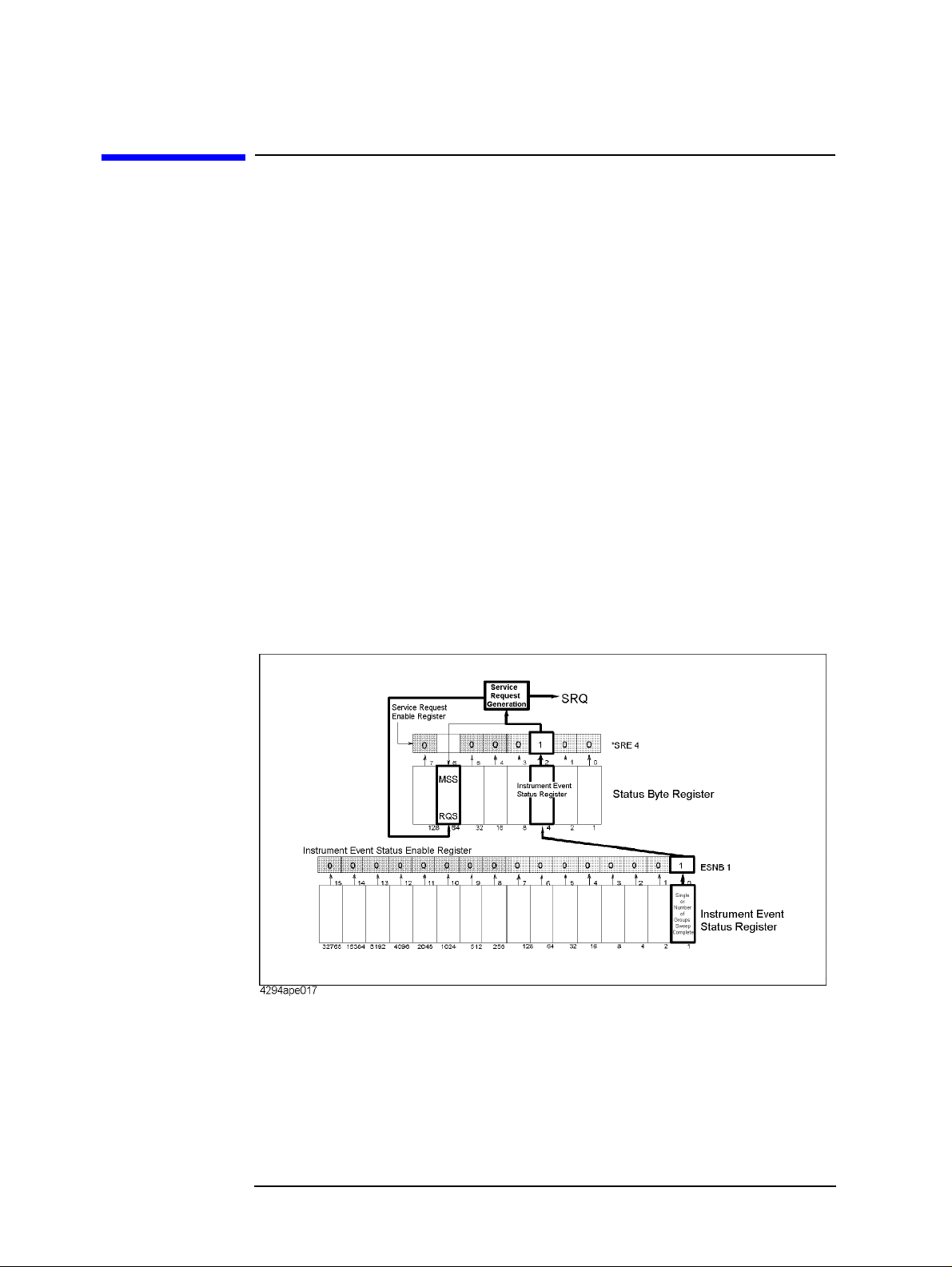
Starting a Measurement (Trigger) and Detecting the Completion of a Measurement
(End of Sweeps)
Waiting for the Completion of One or More Sweeps (Detecting the Completion of a Measurement)
Waiting for the Com pletion of One or More Sweeps (Detecting the Completion of a Measurement)
Using the status register
Y o u can detect the state of the HP 4294A through the status register . The com pletion of one
or more sweeps is indicated by the instrument event status register. To detect the
completion of one or more sweeps from a program using th e information in this register,
use an SRQ (service request).
To detect the completion of one or more sweeps using an SRQ, use the commands below.
• “*SRE” on page 220
• “ESNB” on page 271
The procedure is as follows:
Step 1.
Step 2.
Step 3.
Figure 5-2 SRQ generation sequence (at the end of one or more sweeps)
Make the setting so that the HP 4294A generates an SRQ when the sweep completion bit in
the instrument event status register is set to “1.”
Generates a trigger to start one or more sweeps.
Performs the interrupt processing in the program when an SRQ is generated.
Example 5-1 is a sample program using an SRQ to detect the completion of sweeps. This
program is stored on the sample program disk as the swp_srq.bas file.
This program sets the sweep averaging factor to 4, makes the SRQ setting, and then
performs 4 sweeps. When an SRQ is generated at the completion of the sweeps, the
program displays the completi on message and th en finishes.
74 Chapter 5
Page 75

Starting a Measurement (Trigger) and Detecting the Completion of a Measurement
(End of Sweeps)
Waiting for the Completion of One or More Sweeps (Detecting the
Completion of a Measurement)
Lines 30 to 90 Identifies the external controller and Instrument BASIC and sets the
HP-IB address and the select code.
Lines 110 to 130 Sets the trigger source to the internal trigger and sets the sweep
averaging factor to 4.
Lines 150 to 160 Enables bit 0 (sweep completion bit) in the instrument event status
register and sets bit 2 in the service request enable register to 1.
NOTE A bit, to indicate the completion of data measurements for adapter setting, user calibration,
and fixture compensation, is provided separat e ly from the sweep completion bit. To detect
the completion of these measurements, enable bit 8 in the instrument event status register.
Lines 170 to 190 Clears the status byte register and the instrument event status register.
Lines 210 to 220 Sets the branch destination for t he SR Q i nt err upt an d enables the SRQ
interrupt. Line 230 Executes the command to perform 4 sweeps. Line 250 Waits for the completion of the sweeps. Line 260 Displays the sweep completion message.
Example 5-1 Detecting the completion of sweeps using an SRQ
10 DIM Buff$[9] 20 INTEGER Scode 30 IF SYSTEM$("SYSTEM ID")="HP4294A" THEN 40 ASSIGN @Hp4294a TO 800 50 Scode=8 60 ELSE 70 ASSIGN @Hp4294a TO 717 80 Scode=7 90 END IF 100 ! 110 OUTPUT @Hp4294a;"TRGS INT" 120 OUTPUT @Hp4294a;"AVERFACT 4" 130 OUTPUT @Hp4294a;"AVER ON" 140 ! 150 OUTPUT @Hp4294a;"ESNB 1" 160 OUTPUT @Hp4294a;"*SRE 4" 170 OUTPUT @Hp4294a;"*CLS" 180 OUTPUT @Hp4294a;"*OPC?" 190 ENTER @Hp4294a;Buff$ 200 ! 210 ON INTR Scode GOTO Swp_end 220 ENABLE INTR Scode;2 230 OUTPUT @Hp4294a;"NUMG 4" 240 PRINT "Waiting..." 250 Swp_wait: GOTO Swp_wait 260 Swp_end: PRINT "Sweep Complete" 270 END
Chapter 5 75
Page 76

Starting a Measurement (Trigger) and Detecting the Completion of a Measurement
(End of Sweeps)
Waiting for the Completion of One or More Sweeps (Detecting the
Completion of a Measurement)
Using the *OPC? command
The “SING” command on page 389 and “NUMG” command on page 319 are overlap
commands, whose execution is finished at the completion of one or more sweeps.
Therefore, if you start one or more sweeps using these commands, you can detect the
completion of them using the following command.
• “*OPC?” on page 219
Example 5-2 shows a sample program to detect the completion of a sweep using the
“*OPC?” command. This program is stored on the sample program disk as the
swp_opc.bas file.
This program starts a sweep using the “SING” command, waits for the completion of the
execution of the “SING” command using the “*OPC?” comm and (the completion of a
single sweep), displays a message at the completion of the sweep, and then finishes.
Lines 20 to 60 Identifies the external controller and Instrument BASIC and sets the
HP-IB address.
Line 80 Sets the trigger source to the internal trigger.
Lines 90 Starts a single sweep.
Lines 110 to 120 Executes the “*OPC?” command and waits for 1 to be read out (the
completion of the sweep). Line 130 Displays the sweep completion message.
Example 5-2 Detecting the completion of a sweep using the “*OPC?” command
10 DIM Buff$[9] 20 IF SYSTEM$("SYSTEM ID")="HP4294A" THEN 30 ASSIGN @Hp4294a TO 800 40 ELSE 50 ASSIGN @Hp4294a TO 717 60 END IF 70 ! 80 OUTPUT @Hp4294a;"TRGS INT" 90 OUTPUT @Hp4294a;"SING" 100 PRINT "Waiting..." 110 OUTPUT @Hp4294a;"*OPC?" 120 ENTER @Hp4294a;Buff$ 130 PRINT "Sweep Complete" 140 END
Inserting a wait
You can make a setting so that the controller waits for the completion of one or more
sweeps performed by the HP 4294A (for example, in the case of HP BASIC, use the WAIT
command). This method is simple but, if you set an inappr opriate wait, unexpected errors
could occur.
76 Chapter 5
Page 77

6 Reading/Writing Measurement Data
This chapter describes how to read or write measurement data and h ow to obtain level
monitoring and limit test results.
77
Page 78

Reading/Writing Measurement Data
Data Transfer Format
Data Transfer Format
The format applicable when you read measuremen t param e ter settings from HP 4294A (as
when you read the sweep start point with “STAR?”) is the ASCII format, regardless of
which data transfer format has been specified.
You can select either the ASCII format (default) or one of the binary formats for reading
measurement data, waveform analysis result and so on from HP 4294A (as when you read
data trace array with “OUTPDTRC?”). As for binary formats, the IEEE 32-bit floating
point format, IEEE 64-bit floating point format, and MS-DOS personal computer format
are available to choose from. You can select the appropriate format f or your controller from
these options. Use the following commands for selecting a desired data transfer format:
Data Transfer Format Commands
IEEE 32-bit floating point format “FORM2” on page 273 IEEE 64-bit floating point format “FORM3” on page 273 ASCII format (Default) “FORM4” on page 273 MS-DOS personal computer format “FORM5” on page 273
ASCII format (Form 4)
When you select the ASCII format as data transfer format, numbers are transferred as
ASCII bytes, each of which corresponds to one of th e fo rmats shown below. Note also that
numbers are separated from one another with a comma (“,”) in accordance with the
IEEE488.2 specification.
NOTE Each numeric data character string is different in length from others. Before extracting
each piece of data from character strings, you must remember, therefore, that commas do
not always appear at the same locations.
• Integer Format
Figure 6-1 shows this format. Numbers are expressed as integers. For example, 201 is
expressed as “+201” or “201.”
Figure 6-1 Integer Format
78 Chapter 6
Page 79
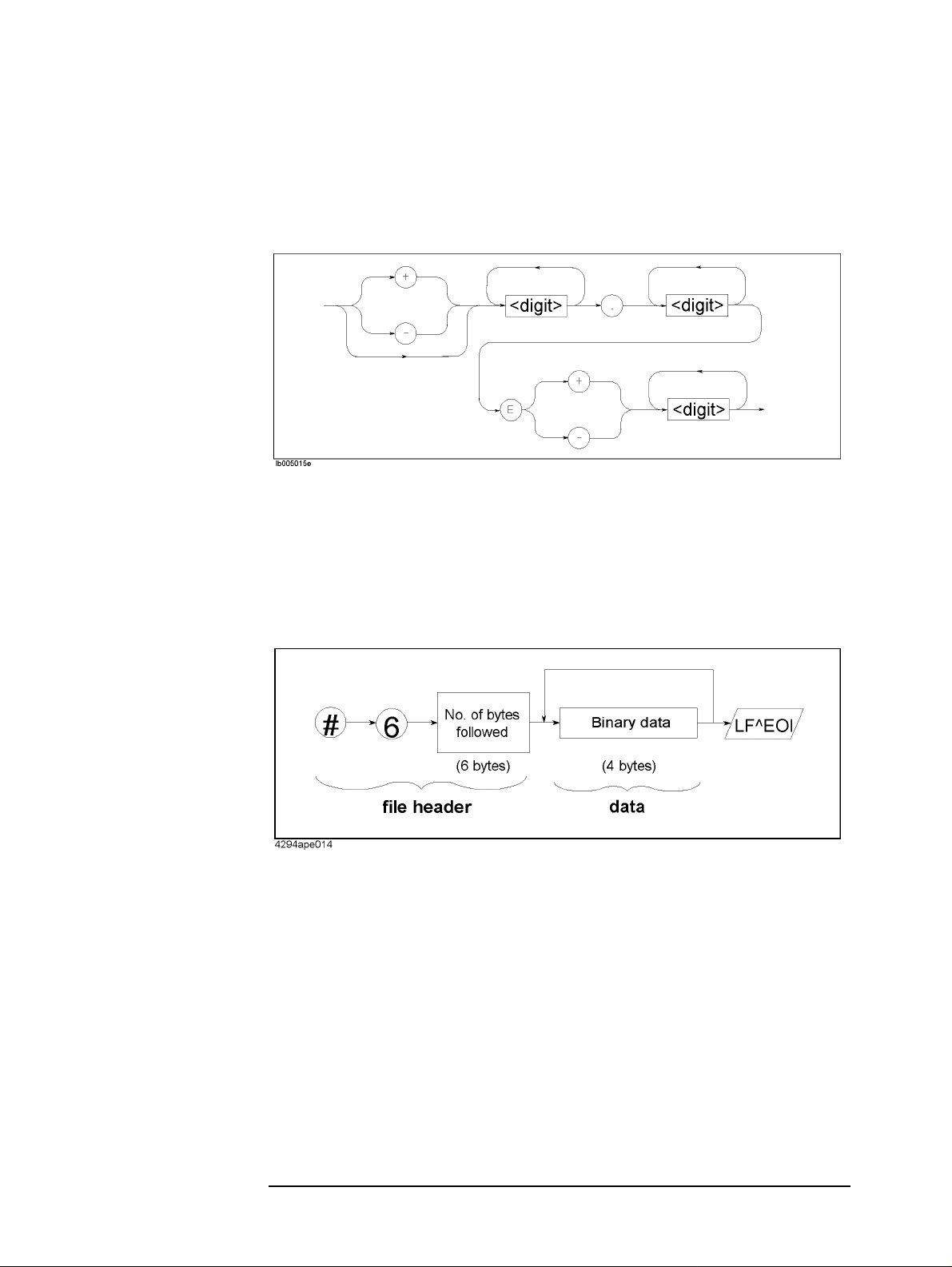
• Floating Point Format
Figure 6-2 shows this format. Numbers are expressed with floating points. For
example, 1000 is expressed as “1.0E3.”
Figure 6-2 Floating Point Format
IEEE 32-bit floating point format (Form 2)
Reading/Writing Measurement Data
Data Transfer Format
With this format, each number is expressed with four bytes. Therefore, data containing 201
measured values is 1,608 bytes long (2 pieces of data p er measurement point) . Numbers are
transferred in the format shown in Figure 6-3.
Figure 6-3 IEEE 32-bit Floating Point Data Transfer Format
Chapter 6 79
Page 80

Reading/Writing Measurement Data
Data Transfer Format
IEEE 64-bit floating point format (Form 3)
With this format, each number is expressed with eight bytes. Therefore, data containing
201 measured values is 3,216 bytes long (2 pieces of data per measurement point).
Numbers are transferred in the format shown in Figure 6-4.
Figure 6-4 IEEE 64-bit Floating Point Data Transfer Format
MS-DOS personal computer format (Form 5)
This format is identical to the IEEE 32-bit floating point format, excep t that data bytes are
arranged in the reverse order. You do not need to reformat your data when you manipulate
it on the personal computer in the DOS environment.
80 Chapter 6
Page 81
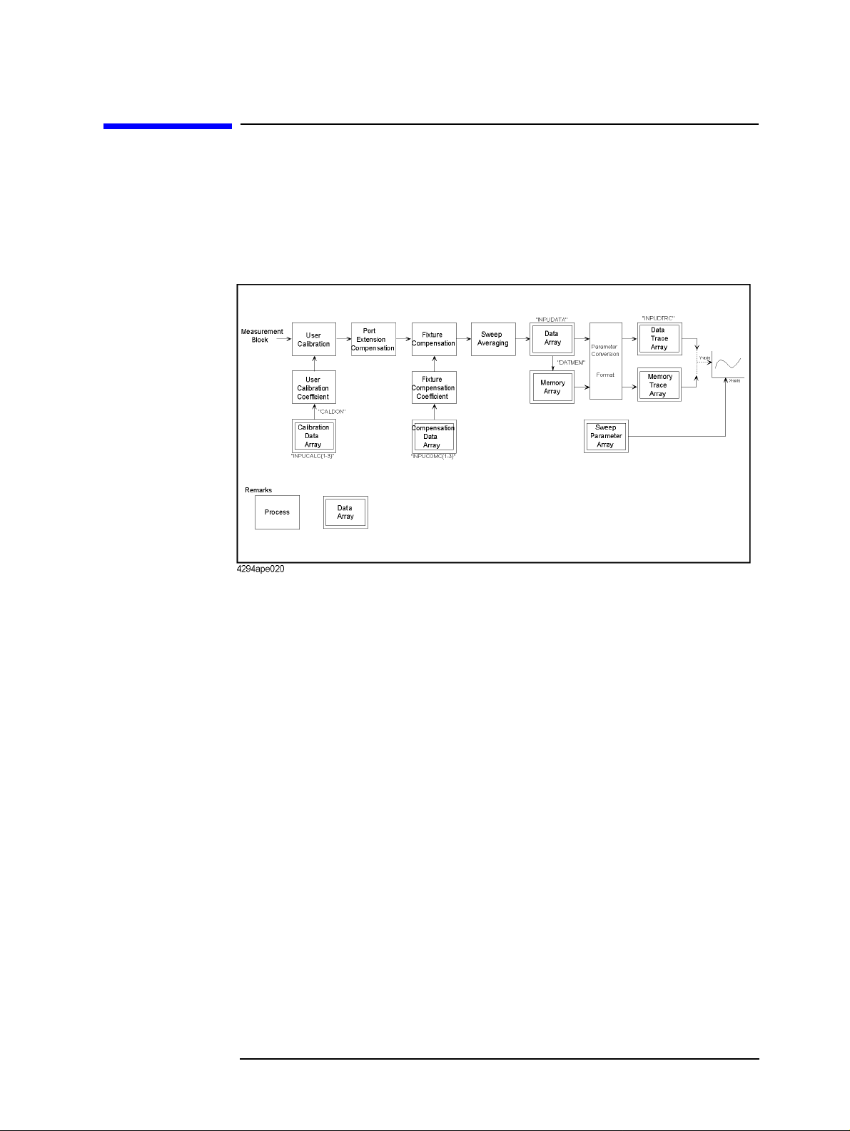
Internal Data Processing
Data processing sequence
Figure 6-5 outlines the sequence of data processing performed within HP 4294A.
Figure 6-5 HP 4294A Data Processing Sequence
Reading/Writing Measurement Data
Internal Data Processing
The following describes each of data arrays within Figure 6-5:
Internal data array
Data array
Data array contains the result of user calibration, port extension compensation, sweep
averaging and fixture compensation performed on the measured data. This result is stored
as complex number (R-X). Use the following commands to read or write data array:
• “OUTPDATA?” on page 330
• “OUTPDATAP?” on page 330
• “INPUDATA” on page 277
Memory array
Memory array contains a copy of the data ar ray availabl e when the “DATMEM” command
on page 244 is executed. Use the following commands to read memory array. Note that you
cannot write any memory array.
• “OUTPMEMO?” on page 340
• “OUTPMEMOP?” on page 340
Chapter 6 81
Page 82

Reading/Writing Measurement Data
Internal Data Processing
Data trace array
Data trace array contains data that appears on the screen as data trace, that is, the result of
measurement parameter conver sion and arithmeti c performed on data array. Array is stored
as complex number, regardless of whether the data is a scalar or vector. Therefore, if the
data is a scalar, “0” is stored in th e imaginary numb er part. Use the following command s to
read or write data trace array:
• “OUTPDTRC?” on page 333
• “OUTPDTRCP?” on page 334
• “INPUDTRC” on page 278
Memory trace array
Memory trace array contains data that appears on the screen as memory trace, that is, the
result of parameter conversion performed on memory array. Use the following commands
to read memory trace array. Note that you cannot write any memory trace array.
• “OUTPMTRC?” on page 343
• “OUTPMTRCP?” on page 344
Calibration data array
Calibration data array contains open, short, or load measurement data used for calculation
of user calibration coefficient. This data is stored a s comp lex number. Three different types
of arrays are available to choose from depending on the type of measurement data (open,
short, or load data).
Array Number
*1
Stored Data
1 Open measurement data for user calibration coefficient calculation 2 Short measurement data for user calibration coefficient calculation 3 Load measurement data for user calibration coefficient calculation
*1.This number corresponds to the number provided at the end of the command.
Use the following commands to read or write calibration data array:
• “OUTPCALC{1-3}?” on page 328
• “INPUCALC{1-3}” on page 276
Calibration coefficient is calculated and stored in volatile memory (RAM) when all arrays
are written.
82 Chapter 6
Page 83

Reading/Writing Measurement Data
Internal Data Processing
Compensation data array
Compensation data array contains open, short, or load measurement data used for
calculation of fixture compensation coefficient. This data is stored as complex number.
Three different types of arrays are available to choose from depending on the type of
measurement data (open, short, or load data).
Array Number
1
2
3
*1
Open measurement data for fixture compensation coefficient calculation
Short measurement data for fixture compensation coefficient calculation
Load measurement data for fixture compensation coefficient calculation
Stored Data
*1. This number corresponds to the number provided at the end of the command.
Use the following commands to read or write compensation data array:
• “OUTPCOMC{1-3}?” on page 329
• “INPUCOMC{1-3}” on page 277
Sweep parameter array
Sweep parameter array contains sweep parameters for all measurement points. Use the
following commands to read sweep parameter array. Note that you cannot write any sweep
parameter array.
• “OUTPSWPRM?” on page 349
• “OUTPSWPRMP?” on page 349
Saving array as file
You can save internal data array as a file. This feature saves time and effort when you wish
to temporarily save data array as a file without performing any arithmetic for recalling it
later. Use the following commands to save or recall internal data array. See Chapter 8 ,
“Saving/Recalling a Measurement Result/Measurement Setup,” for more information.
• “SAVCAL” on page 369
• “SAVDAT” on page 370
• “SAVDTRC” on page 372
• “SAVMEM” on page 372
• “SAVMTRC” on page 373
• “SAVDASC” on page 369
• “SAVDDAT” on page 370
• “RECD” on page 361
Chapter 6 83
Page 84

Reading/Writing Measurement Data
Reading/Writing Data
Reading/Writing Data
Reading/writing measurement data
Reading/writing array in the ASCII format
Example 6-1 shows an example of reading and writing array in the ASCII format. This
program is available under the filename of “data_b2a.bas” in the sample program disk.
This program reads the data trace array for trace B in the ASCII format and writes it to the
data trace array for trace A.
Lines 30 to 70 Identifies the external controller and Instrument BASIC and sets the
HP-IB address.
Line 90 Substitutes the number of measurement points to “Nop ” (variable).
Line 110 to 120 Specifies ASCII format as data transfer format, an d sets the number of
measurement points to Nop.
Line 140 to 150 Holds the trigger and displays traces A and B on separate screens.
Lines 160 to 190 Specifies trace B as active trace, performs auto scaling, and reads the
display format to assign it “Fmt$” (variable). Lines 210 to 220 Reads the data trace array for trace B and stores it in Trc(*). Lines 240 to 250 Specifies trace A as active trace and sets the display format to “Fmt$.” Line 260 Writes “Trc(*)” to the data trace array for trace A. Line 270 Performs auto scaling.
Example 6-1 Reading/Writing Data Trace Array in the ASCII Format
10 DIM Trc(1:201,1:2),Fmt$[9] 20 INTEGER Nop 30 IF SYSTEM$("SYSTEM ID")="HP4294A" THEN 40 ASSIGN @Hp4294a TO 800 50 ELSE 60 ASSIGN @Hp4294a TO 717 70 END IF 80 ! 90 Nop=201 100 ! 110 OUTPUT @Hp4294a;"FORM4" 120 OUTPUT @Hp4294a;"POIN ";Nop 130 ! 140 OUTPUT @Hp4294a;"HOLD" 150 OUTPUT @Hp4294a;"SPLD ON" 160 OUTPUT @Hp4294a;"TRAC B" 170 OUTPUT @Hp4294a;"AUTO" 180 OUTPUT @Hp4294a;"FMT?" 190 ENTER @Hp4294a;Fmt$ 200 ! 210 OUTPUT @Hp4294a;"OUTPDTRC?" 220 ENTER @Hp4294a;Trc(*) 230 !
84 Chapter 6
Page 85

Reading/Writing Measurement Data
Reading/Writing Data
240 OUTPUT @Hp4294a;"TRAC A"
250 OUTPUT @Hp4294a;"FMT "&Fmt$
260 OUTPUT @Hp4294a;"INPUDTRC ";Trc(*)
270 OUTPUT @Hp4294a;"AUTO"
280 !
290 END
Reading/writing data array in a binary format
Example 6-2 shows an example of reading and writing array in a binary format. This
program is available under the filename of “mem2dat.bas” in the sample program disk.
This program reads the memory trace array fo r trace A in the IEEE 64-bit floating point
format and writes it to the data trace array.
Lines 30 to 90 Identifies the external controller and Instrument BASIC and sets the
HP-IB address.
Line 110 to 120 Substitutes the trace selected as active trace and the number of
measurement points to the corresponding variables (Act_trc$, Nop),
respectively.
Line 140 to 150 Specifies the IEEE 64-bit floating point fo rmat as da ta transfer format,
and sets the number of measurement points to Nop.
Lines 170 to 180 Holds the trigger and sets the active trace to Act_trc$.
Lines 190 to 200 Clears error queue and specifies memory trace as the trace to be
displayed.
Lines 210 to 220 Checks for errors.
Line 240 An error message appears if error No.34 (error that occurs if an
attempt is made to use memory trace when no data has been stored as
memory trace). Then, program execution stops without performing
any operations.
Lines 260 to 270 Executes a memory trace array read command, reads the header, and
substitutes it to “Header$” (variable).
Line 280 Reads the memory trace array and stores it in “Trc(*)” (array variable).
Binary data must be read without being formatted. Therefore, an I/O
path (@Binary) that has been set to read without being formatted is
used.
Line 290 Reads the terminator (LF^EOI) provided at the end of the data.
Line 310 Specifies data trace as the trace to be displayed.
Lines 320 to 330 Writes “Trc(*)” to the data trace array. To do this, a data trace array
write command with “Header$” (header) is sent first. Next, “Trc(*)”
(data part) is sent. When the data part is sent, an I/O path (@Binary)
that has been set to send without being formatted is used.
Chapter 6 85
Page 86

Reading/Writing Measurement Data
Reading/Writing Data
Example 6-2 Reading/Writing Data Trace Array in a Binary Format
10 DIM Trc(1:201,1:2),Act_trc$[9],Err_mes$[50],Header$[9],Buff$[9] 20 INTEGER Err_no,Nop 30 IF SYSTEM$("SYSTEM ID")="HP4294A" THEN 40 ASSIGN @Hp4294a TO 800 50 ASSIGN @Binary TO 800;FORMAT OFF 60 ELSE 70 ASSIGN @Hp4294a TO 717 80 ASSIGN @Binary TO 717;FORMAT OFF 90 END IF 100 ! 110 Act_trc$="A" 120 Nop=201 130 ! 140 OUTPUT @Hp4294a;"FORM3" 150 OUTPUT @Hp4294a;"POIN ";Nop 160 ! 170 OUTPUT @Hp4294a;"HOLD" 180 OUTPUT @Hp4294a;"TRAC "&Act_trc$ 190 OUTPUT @Hp4294a;"*CLS" 200 OUTPUT @Hp4294a;"DISP MEMO" 210 OUTPUT @Hp4294a;"OUTPERRO?" 220 ENTER @Hp4294a;Err_no,Err_mes$ 230 IF Err_no=34 THEN 240 PRINT Err_mes$ 250 ELSE 260 OUTPUT @Hp4294a;"OUTPMTRC?" 270 ENTER @Hp4294a USING "#,8A";Header$ 280 ENTER @Binary;Trc(*) 290 ENTER @Hp4294a USING "#,1A";Buff$ 300 ! 310 OUTPUT @Hp4294a;"DISP DATA" 320 OUTPUT @Hp4294a;"INPUDTRC "&Header$; 330 OUTPUT @Binary;Trc(*),END 340 END IF 350 ! 360 END
86 Chapter 6
Page 87

Reading/Writing Measurement Data
Reading/Writing Data
Reading level monitoring results
To read monitoring result s of oscillator (OSC) power and DC bias levels, you need to use
the following commands to turn ON the level monitor function b e fore startin g
measurements:
• “OMON” on page 320
• “BMON” on page 232
Use the following commands to read the level moni toring results:
• “OUTPVAC?” on page 349
• “OUTPVACP?” on page 350
• “OUTPIAC?” on page 335
• “OUTPIACP?” on page 336
• “OUTPDC?” on page 331
• “OUTPDCP?” on page 331
Example 6-3 shows a sample program to read the level monitoring results. This program is
available under the filename of “lvl_mon.bas” in the sample program disk.
This program specifies the oscillator power and DC bias levels, turns ON the level monitor
function, performs sweep once, and reads and displays the level monitoring results.
Lines 50 to 110 Identifies the external controller and Instrument BASIC and sets the
HP-IB address.
Lines 130 to 170 Substitutes the selected sign al source output mode, the signal source
output level, the DC bias level, the DC bias range, and the selected DC
bias monitor func tion the corresponding variables (Osc_mode$,
Osc_pow, Dc_bias, Dc_b_rng$, Mon_bias$), respectively.
Lines 190 to 220 Resets the HP4294A and then sets the sweep start point, the sweep
stop point, and the number of measurement points to 10 MHz, 20
MHz, and 11, respectively.
Lines 230 to 270 Sets the signal source output mode, the signal source output level, the
DC bias level, and the DC bias range to Osc_mode$, Osc_pow,
Dc_bias and Dc_b_rng$, respectively.
Lines 280 to 300 Turns ON the DC bias output and the signal source output level
monitor function and sets the selected DC bias monitor function to
Mon_bias$.
Lines 320 to 340 Performs sweep once and waits for the sweep to be complete.
Line 360 Specifies the IEEE 64-bit floating point format as data transfer format.
Lines 380 to 410 Reads the signal source volt age level fo und by mo nitoring and stores it
in “Mon_osc_v(*).”
Lines 430 to 460 Reads the signal source current level fou nd by monit orin g and stores it
in “Mon_osc_i(*).”
Lines 480 to 510 Reads the DC bias level found by monitoring and stores it in
“Mon_bias(*).”
Lines 530 to 560 Reads the sweep parameter array and stores it in “Swp_prm(*).”
Chapter 6 87
Page 88

Reading/Writing Measurement Data
Reading/Writing Data
Lines 580 to 630 Displays the contents of “Swp_prm(*)”, “Mon_osc_v(*)”,
“Mon_osc_i(*)”, and “Mon_bias(*).”
Example 6-3 Reading Level Monitoring Results
10 DIM Mon_osc_v(1:11),Mon_osc_i(1:11),Mon_bias(1:11),Swp_prm(1:11) 20 DIM Osc_mode$[9],Mon_bias$[9],Header$[9],Buff$[9],Img$[30] 30 REAL Osc_pow,Dc_bias 40 CLEAR SCREEN 50 IF SYSTEM$("SYSTEM ID")="HP4294A" THEN 60 ASSIGN @Hp4294a TO 800 70 ASSIGN @Binary TO 800;FORMAT OFF 80 ELSE 90 ASSIGN @Hp4294a TO 717 100 ASSIGN @Binary TO 717;FORMAT OFF 110 END IF 120 ! 130 Osc_mode$="VOLT" 140 Osc_pow=1.0 150 Dc_bias=12.0 160 Dc_b_rng$="M10" 170 Mon_bias$="VOLT" 180 ! 190 OUTPUT @Hp4294a;"PRES" 200 OUTPUT @Hp4294a;"STAR 10MHZ" 210 OUTPUT @Hp4294a;"STOP 20MHZ" 220 OUTPUT @Hp4294a;"POIN 11" 230 OUTPUT @Hp4294a;"POWMOD "&Osc_mode$ 240 OUTPUT @Hp4294a;"POWE ";Osc_pow 250 OUTPUT @Hp4294a;"DCMOD VOLT" 260 OUTPUT @Hp4294a;"DCV ";Dc_bias 270 OUTPUT @Hp4294a;"DCRNG "&Dc_b_rng$ 280 OUTPUT @Hp4294a;"DCO ON" 290 OUTPUT @Hp4294a;"OMON ON" 300 OUTPUT @Hp4294a;"BMON "&Mon_bias$ 310 ! 320 OUTPUT @Hp4294a;"SING" 330 OUTPUT @Hp4294a;"*OPC?" 340 ENTER @Hp4294a;Buff$ 350 ! 360 OUTPUT @Hp4294a;"FORM3" 370 ! 380 OUTPUT @Hp4294a;"OUTPVAC?" 390 ENTER @Hp4294a USING "#,8A";Header$ 400 ENTER @Binary;Mon_osc_v(*) 410 ENTER @Hp4294a USING "#,1A";Buff$ 420 ! 430 OUTPUT @Hp4294a;"OUTPIAC?" 440 ENTER @Hp4294a USING "#,8A";Header$ 450 ENTER @Binary;Mon_osc_i(*) 460 ENTER @Hp4294a USING "#,1A";Buff$ 470 ! 480 OUTPUT @Hp4294a;"OUTPDC?" 490 ENTER @Hp4294a USING "#,8A";Header$ 500 ENTER @Binary;Mon_bias(*) 510 ENTER @Hp4294a USING "#,1A";Buff$ 520 ! 530 OUTPUT @Hp4294a;"OUTPSWPRM?" 540 ENTER @Hp4294a USING "#,8A";Header$ 550 ENTER @Binary;Swp_prm(*) 560 ENTER @Hp4294a USING "#,1A";Buff$ 570 ! 580 Img$="D.2DE,X,Z.4D,X,D.4DE,X,2D.3D"
88 Chapter 6
Page 89

Reading/Writing Measurement Data
Reading/Writing Data
590 PRINT "LEVEL MONITOR RESULT"
600 PRINT "Freq[Hz] OscV[V] OscI[A] DC V[V]"
610 FOR I=1 TO 11
620 PRINT USING Img$;Swp_prm(I),Mon_osc_v(I),Mon_osc_i(I),Mon_bias(
I)
630 NEXT I
640 END
Reading limit test results
To read limit test results, use the following commands:
• “OUTPFAIP?” on page 335
• “OUTPLIML ?” on page 338
• “OUTPLIMF?” on page 338
• “OUTPLIMM?” on page 339
Example 6-3 shows a sample program to read limit test results. This program is available
under the filename of “lim_test.bas” in the sample program disk.
This program creates a limit line table, turns ON the limit test fun c tion, performs sweep
once, and reads and displays those pieces of measurement data found to be unacceptable.
Lines 100 to 140 Identifies the external controller and Instrument BASIC and sets the
HP-IB address.
Lines 150 to 220 Substitutes the measurement parameter selection, the sweep start
point, the sweep stop point, the number of measurement points, the
maximum and minimum values of screen for trace A, and the
maximum and minimum values of screen for trace B to the
corresponding variables (Meas_para$, Star, Stop, Nop, Top_a, Btm_ a,
Top_b, Btm_b), respectively.
Lines 240 to 410 Substitutes the start point, the upper and lower limits for start point,
the stop point, and the upper and lower limits for stop po int for each of
the limit line table segments to the corresponding variables
(Lim_star_a(*), U_lim_star_a(*), L_lim_star_a(*), Lim_stop_a(*),
U_lim_stop_a(*), L_lim_stop_a(*)).
Lines 430 to 600 Substitutes the parameters of the limit line table for trace B to the
corresponding variables (Lim_star_b(*), U_lim_star_b(*),
L_lim_star_b(*), Lim_stop_b(*), U_lim_stop_b(*),
L_lim_stop_b(*)).
Lines 620 to 670 Resets the HP4294A and then sets the measurement parameter, the
sweep start point, the sweep stop point, and the number of
measurement points to the corresponding variables (Meas_para$, Star,
Stop, Nop), respectiv ely and enables traces A and B to be displayed on
separate screens.
Lines 690 to 710 Specifies trace A as active trace and sets the maximum and minimum
value of screen for trace A to Top_a, Btm_a, respectively.
Lines 720 to 850 Creates a limit line table for trace A and turns ON the limit test
function.
Line 870 to 890 Specifies trace B as active trace and sets the maximum and minimum
Chapter 6 89
Page 90

Reading/Writing Measurement Data
Reading/Writing Data
value of screen for trace B to Top_b, Btm_b, respectively.
Lines 900 to 1030 Creates a limit line table for trace B and turns ON the limit test
function.
Lines 1050 to 1070 Performs sweep once and waits for the sweep to be complete.
Lines 1090 to 1110 Specifies trace A as active trace and then reads the number of
measurement points for trace A where the measurement data was
found to be unacceptable.
Lines 1130 to 1230 Specifies the ASCII format as data transfer format and reads and
displays the sweep parameter value, test result, and upper and lower
limits for each of the measurements points for trace A where the
measurement data was found to be unacceptable.
Line 1250 Displays a message if the measurement data at all measurement points
for trace A was found to be acceptable.
Lines 1280 to 1300 Specifies trace B as active trace and then reads the number of
measurement points for trace B where the measurement data was
found to be unacceptable.
Lines 1320 to 1420 Specifies the ASCII format as data transfer format and reads and
displays the sweep parameter value, test result, and upper and lower
limits for each of the measurements points for trace B where the
measurement data was found to be unacceptable.
Line 1440 Displays a message if the measurement data at all measurement points
for trace B was found to be acceptable.
90 Chapter 6
Page 91

Example 6-4 Reading Limit Test Results
10 REAL Star,Stop,Top_a,Btm_a,Top_b,Btm_b 20 REAL Fail_res_a(1:41,1:4),Fail_res_b(1:41,1:4) 30 REAL Lim_star_a(1:3),U_lim_star_a(1:3),L_lim_star_a(1:3) 40 REAL Lim_stop_a(1:3),U_lim_stop_a(1:3),L_lim_stop_a(1:3) 50 REAL Lim_star_b(1:3),U_lim_star_b(1:3),L_lim_star_b(1:3) 60 REAL Lim_stop_b(1:3),U_lim_stop_b(1:3),L_lim_stop_b(1:3) 70 DIM Meas_para$[9],Buff$[9] 80 INTEGER Nop,Fail_nop 90 CLEAR SCREEN 100 IF SYSTEM$("SYSTEM ID")="HP4294A" THEN 110 ASSIGN @Hp4294a TO 800 120 ELSE 130 ASSIGN @Hp4294a TO 717 140 END IF 150 Meas_para$="CSD" 160 Star=1.0E+7 170 Stop=5.0E+7 180 Nop=41 190 Top_a=2.0E-5 200 Btm_a=0. 210 Top_b=.02 220 Btm_b=0. 230 ! 240 Lim_star_a(1)=1.0E+7 250 U_lim_star_a(1)=1.2E-5 260 L_lim_star_a(1)=8.E-6 270 Lim_stop_a(1)=2.0E+7 280 U_lim_stop_a(1)=1.2E-5 290 L_lim_stop_a(1)=8.E-6 300 Lim_star_a(2)=2.0E+7 310 U_lim_star_a(2)=1.2E-5 320 L_lim_star_a(2)=8.E-6 330 Lim_stop_a(2)=4.0E+7 340 U_lim_stop_a(2)=1.5E-5 350 L_lim_stop_a(2)=5.E-6 360 Lim_star_a(3)=4.0E+7 370 U_lim_star_a(3)=1.5E-5 380 L_lim_star_a(3)=5.E-6 390 Lim_stop_a(3)=5.0E+7 400 U_lim_stop_a(3)=1.5E-5 410 L_lim_stop_a(3)=5.E-6 420 ! 430 Lim_star_b(1)=1.0E+7 440 U_lim_star_b(1)=.005 450 L_lim_star_b(1)=0. 460 Lim_stop_b(1)=2.0E+7 470 U_lim_stop_b(1)=.005 480 L_lim_stop_b(1)=0. 490 Lim_star_b(2)=2.0E+7 500 U_lim_star_b(2)=.005 510 L_lim_star_b(2)=0. 520 Lim_stop_b(2)=4.0E+7 530 U_lim_stop_b(2)=.01 540 L_lim_stop_b(2)=0. 550 Lim_star_b(3)=4.0E+7 560 U_lim_star_b(3)=.01 570 L_lim_star_b(3)=0. 580 Lim_stop_b(3)=5.0E+7 590 U_lim_stop_b(3)=.01 600 L_lim_stop_b(3)=0. 610 !
Reading/Writing Measurement Data
Reading/Writing Data
Chapter 6 91
Page 92

Reading/Writing Measurement Data
Reading/Writing Data
620 OUTPUT @Hp4294a;"PRES"
630 OUTPUT @Hp4294a;"MEAS "&Meas_para$
640 OUTPUT @Hp4294a;"STAR ";Star
650 OUTPUT @Hp4294a;"STOP ";Stop
660 OUTPUT @Hp4294a;"POIN ";Nop
670 OUTPUT @Hp4294a;"SPLD ON"
680 !
690 OUTPUT @Hp4294a;"TRAC A"
700 OUTPUT @Hp4294a;"TOPV ";Top_a
710 OUTPUT @Hp4294a;"BOTV ";Btm_a
720 OUTPUT @Hp4294a;"EDITLIML"
730 FOR I=1 TO 3
740 OUTPUT @Hp4294a;"LIMSADD"
750 OUTPUT @Hp4294a;"LIMSTAR ";Lim_star_a(I)
760 OUTPUT @Hp4294a;"LIMUSTAR ";U_lim_star_a(I)
770 OUTPUT @Hp4294a;"LIMLSTAR ";L_lim_star_a(I)
780 OUTPUT @Hp4294a;"LIMSTOP ";Lim_stop_a(I)
790 OUTPUT @Hp4294a;"LIMUSTOP ";U_lim_stop_a(I)
800 OUTPUT @Hp4294a;"LIMLSTOP ";L_lim_stop_a(I)
810 OUTPUT @Hp4294a;"LIMSTEST ON"
820 OUTPUT @Hp4294a;"LIMSDON"
830 NEXT I
840 OUTPUT @Hp4294a;"LIMEDONE"
850 OUTPUT @Hp4294a;"LIMITEST ON"
860 !
870 OUTPUT @Hp4294a;"TRAC B"
880 OUTPUT @Hp4294a;"TOPV ";Top_b
890 OUTPUT @Hp4294a;"BOTV ";Btm_b
900 OUTPUT @Hp4294a;"EDITLIML"
910 FOR I=1 TO 3
920 OUTPUT @Hp4294a;"LIMSADD"
930 OUTPUT @Hp4294a;"LIMSTAR ";Lim_star_b(I)
940 OUTPUT @Hp4294a;"LIMUSTAR ";U_lim_star_b(I)
950 OUTPUT @Hp4294a;"LIMLSTAR ";L_lim_star_b(I)
960 OUTPUT @Hp4294a;"LIMSTOP ";Lim_stop_b(I)
970 OUTPUT @Hp4294a;"LIMUSTOP ";U_lim_stop_b(I)
980 OUTPUT @Hp4294a;"LIMLSTOP ";L_lim_stop_b(I)
990 OUTPUT @Hp4294a;"LIMSTEST ON"
1000 OUTPUT @Hp4294a;"LIMSDON"
1010 NEXT I
1020 OUTPUT @Hp4294a;"LIMEDONE"
1030 OUTPUT @Hp4294a;"LIMITEST ON"
1040 !
1050 OUTPUT @Hp4294a;"SING"
1060 OUTPUT @Hp4294a;"*OPC?"
1070 ENTER @Hp4294a;Buff$
1080 !
1090 OUTPUT @Hp4294a;"TRAC A"
1100 OUTPUT @Hp4294a;"OUTPFAIP?"
1110 ENTER @Hp4294a;Fail_nop
1120 !
1130 IF Fail_nop>0 THEN
1140 OUTPUT @Hp4294a;"FORM4"
1150 OUTPUT @Hp4294a;"OUTPLIMF?"
1160 FOR I=1 TO Fail_nop
1170 ENTER @Hp4294a USING "#,K,K,K,K";Fail_res_a(I,1),Fail_res_a(I,
2),Fail_res_a(I,3),Fail_res_a(I,4)
1180 NEXT I
1190 PRINT "-- Trace A Failed Point --"
1200 PRINT "Frequency L_Limit U_Limit"
1210 FOR I=1 TO Fail_nop
1220 PRINT Fail_res_a(I,1),Fail_res_a(I,4),Fail_res_a(I,3)
1230 NEXT I
1240 ELSE
92 Chapter 6
Page 93

Reading/Writing Measurement Data
Reading/Writing Data
1250 PRINT "-- Trace A All Pass --"
1260 END IF
1270 !
1280 OUTPUT @Hp4294a;"TRAC B"
1290 OUTPUT @Hp4294a;"OUTPFAIP?"
1300 ENTER @Hp4294a;Fail_nop
1310 !
1320 IF Fail_nop>0 THEN
1330 OUTPUT @Hp4294a;"FORM4"
1340 OUTPUT @Hp4294a;"OUTPLIMF?"
1350 FOR I=1 TO Fail_nop
1360 ENTER @Hp4294a USING "#,K,K,K,K";Fail_res_b(I,1),Fail_res_b(I,
2),Fail_res_b(I,3),Fail_res_b(I,4)
1370 NEXT I
1380 PRINT "-- Trace B Failed Point --"
1390 PRINT "Frequency L_Limit U_Limit"
1400 FOR I=1 TO Fail_nop
1410 PRINT Fail_res_b(I,1),Fail_res_b(I,4),Fail_res_b(I,3)
1420 NEXT I
1430 ELSE
1440 PRINT "-- Trace B All Pass --"
1450 END IF
1460 !
1470 END
When to read/write data
If a read command is executed while sweep is in progress, the data available when the
command execution starts is read. To ensure accuracy of data you obtain, be sure to wait
until the current sweep is complete before executing a read command. When you consider
the time it takes for your program to be executed to completion, you need to synchronize
the execution of a read command with the completion of the current sweep. To do this, use
the status report structure and the “*OPC?” command on page 219. See “Waiting for the
Completion of One or More Sweeps (Detecting the Completion of a Measurement)” on
page 74 for more information.
To write data properly, you need to execute a write command while no sweep is in
progress. You can write data while sweep is in progre ss. In t his case, h owever, the data you
write will be overwritten. You can hold sweep by executing the “HOLD” command on
page 274.
Chapter 6 93
Page 94

Reading/Writing Measurement Data
Reading/Writing Data
94 Chapter 6
Page 95

7 Processing Measurement Results
This chapter describes how to process measurement results using the marker function, the
equivalent circuit analysis function, the trace bandwidth analysis function, and analysis
commands.
95
Page 96

Processing Measurement Results
Reading Measurement Data at Specific Measurement Points (Using the Marker Function)
Reading Measurement Data at Specific Measurement Points (Using the Marker Function)
You can use the marker to read measurement data at specific points on the trace or search
for the point that meets a specific condition such as the maximum value. You need to use
the following command to turn ON the marker before using it.
• “MKR” on page 305
You can use the main marker (marker No.0; hereafter referred to as the marker) when you
execute the above command. To use one or more submarkers (markers No.1 through 7),
use the following command to turn them ON:
• “SMKR{1-7 }” on page 390
You can also use the ∆ marker to obtain the result of subtraction of the ∆ marker-specified
value from the marker or submarker-specified value or the dif ference between these values.
Use the following command to turn ON the ∆ marker:
• “DMKR” on page 259
When you turn ON a submarker or the ∆ marker, it appears where the marker is currently
located.
Moving the marker
Moving the marker to specific points
Use the following command to move the mar ker, one of the submarkers, or the ∆ marker to
a desired measurement point or sweep parameter value on the trace:
Specific Measurement Point Specifi c S w eep Parameter Value
Marker “MKRP” on page 312 “MKRPRM” on page 313
Submarker “SMKRP{1-7}” on page 391 “SMKRPRM{1-7}” on page 392
Marker “DMKRP” on page 261 “DMKRPRM” on page 262
∆
Moving after search for positions that meet specific conditions
Use the following command to search for an d move the marker to specific positions on the
active trace such as maximum value, minimum value, peak, and measurement parameter
value (target) specified with the “SEATARG” command (page 385):
• “SEAM” on page 379
When the active trace has two or more peaks or targets, the search is made as shown below
after execution of the above command.
Peak Maximum peak (minimum peak if the peak has been defined as
negative peak)
Target Targ et closest to the current marker position
You can use the following commands to sequentially search for the remaining peaks or
targets:
96 Chapter 7
Page 97

Processing Measurement Results
Reading Measurement Data at Specific Measurement Points (Using the
Marker Function)
• “SEANPK” on page 379
• “SEANPKL” on page 379
• “SEANPKR” on page 380
• “SEAL” on page 378
• “SEAR” on page 380
With the search function available with the marker, you can search, as peaks, for
measurement point that meet the definitions given in Figure 7-1. Use the following
commands to define peak:
• “PKDLTX” on page 354
• “PKDLTY” on page 355
• “PKPOL” on page 355
You can use the following command to set the ∆X and ∆Y respectively to the |X
at the marker-specified measurement point.
• “MKRPKD” on page 312
Figure 7-1 Defining Peak for Making Search by the Marker
Search is made over the entire sweep range, unless otherwise specified. You can, however,
use the following commands to limit the range to be searched:
L
| and |YL|
• “PARS” on page 350
• “SEARMAX” on page 381
• “SEARMAXP” on page 382
• “SEARMIN” on page 383
• “SEARMINP ” on page 384
• “MKRTR” on page 314
• “SEARNG” on page 384
• “SEGMNUM” on page 388
Chapter 7 97
Page 98

Processing Measurement Results
Reading Measurement Data at Specific Measurement Points (Using the
Marker Function)
Reading the marker-specified value
Use the following command to read the marker-specified measurement or sweep parameter value:
Measurement Parameter
Marker “OUTPMKR?” on page 342
“MKRVAL?” on page 315 “MKRAUV?” on page 306 “MKRPRM” on page 313
Submarker “OUTPSMKR{1-7}?” on page 348
“SMKRVAL{1-7}?” on
page 393
∆ Marker “OUTPDMKR?” on page 332
“DMKRVAL” on page 263
Used for query
Value
*1
Supplementary Reading for
Measurement Parameter
Value (Vector)
“SMKRAUV{1-7}?” on page
390
“DMKRAUV” on page 260
Used for query
*1
Sweep Parameter Value
Used for query
“SMKRPRM{1-7}” on page 392
Used for query
“DMKRPRM” on page 26 2
Used for query
*1.You can read parameter values only when you use the fixed ∆ marker.
You can use the following commands to display a list of all marker-specified values on the
HP 4294A LCD. Note, however, that you cannot use these commands to read these values.
• “MKRL” on page 307
Sample program for using the marker function
Example 7-1 shows a sample program for using the marker function. This program is
available under the filename of “marker.bas” in the sample program disk.
This program performs sweep once, uses the marker function to search for the maximum
peak and the minimum negative peak in the 10-100 MHz range, provides a submarker at
each of these peaks, and reads and displays the submarker-specified values.
Lines 30 to 70 Identifies the external controller and Instrument BASIC and sets the
HP-IB address.
Lines 90 to 110 Substitutes the lower and upper border values for the search range, and
the trace selected as active trace to the corresponding variables
(Sear_min$, Sear_max$, Act_trc$), respectively.
Lines 130 to 160 Resets the HP4294A, performs sweep once, and waits fo r the sweep to
be complete.
Lines 180 to 190 Sets the trace selected as active trace to Act_trc$, executes the auto
scale to automatically set the scale parameters so that waveforms fit on
the screen.
Lines 210 to 240 Turns ON the marker and sets the lower and upper border values for
the search range to Sear_min$ and Sear_max$, respectively.
Lines 260 to 300 Defines the peak by specifying “0.1/1e6” and “positive” as peak slope
threshold and peak polarity, searches for the peak and moves the
marker to that peak, and positions submarker 1 at the peak.
Lines 320 to 340 Redefines the peak by specifying “negative” as peak polarity, searches
for the peak and moves the marker to that negative peak, and positions
98 Chapter 7
Page 99

Reading Measurement Data at Specific Measurement Points (Using the
submarker 2 at the peak.
Lines 360 to 430 Reads and displays submarker-specified measurement parameter
values.
Example 7-1 Searching for Peaks Using the Marker
10 DIM Sear_min$[9],Sear_max$[9],Act_trc$[9],Buff$[9] 20 REAL P_peak,N_peak 30 IF SYSTEM$("SYSTEM ID")="HP4294A" THEN 40 ASSIGN @Hp4294a TO 800 50 ELSE 60 ASSIGN @Hp4294a TO 717 70 END IF 80 ! 90 Sear_min$="10MHZ" 100 Sear_max$="100MHZ" 110 Act_trc$="A" 120 ! 130 OUTPUT @Hp4294a;"PRES" 140 OUTPUT @Hp4294a;"SING" 150 OUTPUT @Hp4294a;"*OPC?" 160 ENTER @Hp4294a;Buff$ 170 ! 180 OUTPUT @Hp4294a;"TRAC "&Act_trc$ 190 OUTPUT @Hp4294a;"AUTO" 200 ! 210 OUTPUT @Hp4294a;"MKR ON" 220 OUTPUT @Hp4294a;"PARS ON" 230 OUTPUT @Hp4294a;"SEARMIN "&Sear_min$ 240 OUTPUT @Hp4294a;"SEARMAX "&Sear_max$ 250 ! 260 OUTPUT @Hp4294a;"PKDLTX 1MHZ" 270 OUTPUT @Hp4294a;"PKDLTY 0.1" 280 OUTPUT @Hp4294a;"PKPOL POS" 290 OUTPUT @Hp4294a;"SEAM PEAK" 300 OUTPUT @Hp4294a;"SMKR1 ON" 310 ! 320 OUTPUT @Hp4294a;"PKPOL NEG" 330 OUTPUT @Hp4294a;"SEAM PEAK" 340 OUTPUT @Hp4294a;"SMKR2 ON" 350 ! 360 OUTPUT @Hp4294a;"SMKRVAL1?" 370 ENTER @Hp4294a;P_peak 380 OUTPUT @Hp4294a;"SMKRVAL2?" 390 ENTER @Hp4294a;N_peak 400 ! 410 PRINT "Search Range: "&Sear_min$&" - "&Sear_max$ 420 PRINT "Positive Peak: ";P_peak;"[ohm]" 430 PRINT "Negative Peak: ";N_peak;"[ohm]" 440 END
Processing Measurement Results
Marker Function)
Chapter 7 99
Page 100

Processing Measurement Results
Analyzing Measurement Results
Analyzing Measurement Results
Equivalent circuit analysis
With the HP 429 4A, a total of five different circuit models is available to choose from for
equivalent circuit analysis as shown below depending on the type of measurement results
obtained.
Equivalent Circuit Analysis Model Sample Types
Inductor
A
with Large
Core Loss
B
Inductor and
Resistor
Resistor with
C
Large
Resistance
D Capacitor
Typical Frequency Characteristics
*1
E
*1.Measurement parameter: |Z|-θ, Vertical display format: logged |Z| and linear
Oscillator and
Vibrator
θ
Use the following command to select a desired circuit models:
• “EQUC” on page 268
Use the following command to perform equivalent circuit analysis:
• “CALECPARA” on page 235
NOTE The applicable range for equivalent circuit analysis is the same as the range searched by th e
marker .
100 Chapter 7
 Loading...