

Page 1

Agilent 4294A Precision Impedance Analyzer
Operation Manual
Third Edition
SERIAL NUMBERS
This manual applies directly to instruments that have
the serial number prefix JP1KG. For additional important
information about serial numbers, see Appendix A.
Part No. 04294-90020
December 1999
Printed in: Japan
Page 2

Notices
The information contained in this document is subject to change without notice.
This document contains propr ietar y infor mation t hat is pr otect ed by copyri ght. All
rights are reserved. No part of this document may be photocopied, reproduced, or
translated into another language without the prior written consent of Agilent
Technologies.
Agilent Technologies Japan, Ltd.
Kobe Instrument Division
1-3-2, Murotani, Nishi-Ku, Kobe-shi, Hyogo, 651- 2241 Japan
© Copyright 1999 Agilent Technologies Japan, Ltd.
Manual Printing History
The manual’s printing date and part number indicate its current edition. The
printing date changes when a new edition is printed. (Minor corrections and
updates incorporated in reprints do not necessitate a new printing date.) The
manual part number changes when extensive technical changes are incorporated.
April 1999 First Edition May 1999 Second Edition December 1999 Third Edition
Safety Summary
The following general safety precautions must be observed during all phases of
operation, service, and repair of this instrument. Failure to comply with these
precautions or with sp ecific WARNINGS el sewhere in t his manual may impai r the
protection provided by the equipment. Such noncompliance would also violate
safety standards of design, manufacture, and intended use of the instrument.
The Agilent T echnologies assumes no liability for the customer’s failure to comply
with these requirements.
NOTE The Agilent 4294A complies with INSTALLATION CATEGORY II and
POLLUTION DEGREE 2 in IEC61010-1. The Agilent 4294A is an INDOOR
USE product.
2
Page 3

NOTE LEDs in the Agilent 4294A are Class 1 in accordance with IEC60825-1,
CLASS 1 LED PRODUCT.
• Ground the Instrument
To avoid electric shock, the instrument chassis and cabinet must be grounded
with the supplied power cable’s grounding prong.
• DO NOT Operate in an Explosive Atmosphere
Do not operate the instrument in the presence of inflammable gasses or fumes.
Operation of any electrical instrument in such an environment clearly
constitutes a safety hazard.
• Keep Away from Live Circuits
Operators must not remove instrument covers. Component replacement and
internal adjust ments mu st be made by quali fied mai ntenan ce pers onne l. Do not
replace components with the power cable connected. Under certa in conditions,
dangerous voltage levels may exist even with the power cable removed. To
avoid injuries, always disconnect the power and discharge circuits before
touching them.
• DO NOT Service or Adjust Alone
Do not attempt internal servi ce or adj ustment unles s anothe r pers on, capab le of
rendering first aid and resuscitation, is present.
• DO NOT Su bstitute Part s or Modify the Instrument
To avoid the danger of introducing additional hazards, do not install substitute
parts or perform unauthorized modifications to the instrument. Return the
instrument to an Agilent Technologies S ales and Ser vice Of fi ce for ser vice and
repair to ensure that safety features are maintained in operational condition.
• Dangerous Procedure Warnings
Warnings, such as the example below, precede potentially dangerous
procedures throu ghout this manual . Instruct ions contain ed in the war nings must
be followed.
WARNING Dangerous voltage levels, capable of causing death, are present in this
instrument. Use extreme caution when handling, testing, or adjusting this
instrument.
Safety Symbols
General definitions of safety symbols used on the instrument or in manuals are listed belo w.
3
Page 4

Instruction Manual symbol: the product is marked with this symbol when it is
necessary for the user to refer to the instrument manual.
Alternating current.
Direct current.
On (Supply).
Off (Supply).
In-position of push-button switch.
Out-position of push-button switch.
Frame (or chassis) t ermi nal . A c onne ction to the frame (chassis) of the e qui pment ,
which normally includes all exposed metal structure.
WARNING This warning sign denotes a h azard. It ca lls atte ntion to a pr ocedu re, pr actice,
or condition that, if not correctly performed or adhered to, could result in
injury or death to personnel.
CAUTION This Caution sign denotes a hazard. It calls attention to a procedure, practice, or
condition that, if not correctly performed or adhered to, could result in damage to
or destruction of part or all of the product.
NOTE This Note sign denotes important information. It calls attention to a procedure,
practice, or condition that is essential for the user to understand.
Certification
Agilent Technologies certifies that this product met its published specifications at
the time of shipment from the factory. Agilent Technologies further certifies that
its calibration mea surements a re trace able to th e United S tates National I nstitut e of
Standards and Technology, to the extent allowed by the Institution’s calibration
facility or by the calibration fac ilities of other Intern ational S tandards Or ganizati on
members.
Warranty
This Agilent Technologies instrument product is warranted against defects in
material and workmanship for a period corresponding to the individual warranty
periods of its component products. Instruments are warranted for a period of one
4
Page 5

year. Fixtures and adapters are warranted for a period of 90 days. During the
warranty period, Agilent Technologies will, at its option, either repair or replace
products that prove to be defective.
For warranty service or repair, this product must be returned to a service facility
designated by Agilent Technologies. Buyer shall prepay shipping charges to
Agilent Technologies and Agilent Technologies shall pay shipping charges to
return the produ ct to Buyer. However , Buyer shall pay a ll sh ipping char ge s, d uties ,
and taxes for products returned to Agilent Technologies from another country.
Agilent Technologies warrants that its software and firmware designated by
Agilent Technologies for use with an instrument will execute its programming
instruction when properly installed on that instrument. Agilent Technologies does
not warrant that the operation of the instrument, or software, or firmware will be
uninterrupted or error free.
Limitation of Warranty
The foregoing warranty shall not apply to defects resulting from improper or
inadequate maintenance by Buyer, Buyer-supplied software or interfacing,
unauthorized modification or misuse, operation outside the environmental
specifications for the product, or improper site preparation or maintenance.
IMPORTANT No other warranty is expressed or implied. Agilent Technologies specifically
disclaims the implied warranties of merchantability and fitness for a particular
purpose.
Exclusive Remedies
The remedies provided herein are Buyer’s sole and exclusive remedies. Agilent
Technologies shall not be liable for any direct, indirect, special, incidental, or
consequential damages, whether based on contract, tort, or any other legal theory.
Assistance
Product maintenance agreements and other customer assistance agreements are
available for Agilent Technologies products.
For any assistance, contact your nearest Agilent Technologies Sales and Service
Office. Addresses are provided at the back of this manual.
5
Page 6

Typeface Conventions
Bold Boldface type is use d when a term is defined.
For example: icons are symbols.
Italic Italic type is used for emphasis and for titl es
of manuals and other publications.
[Hardkey] Indicates a hardkey labeled “Hardkey.” Softkey Indicates a softkey labeled “Softkey.” [Hardkey] - Softkey1 - Softkey2 Indicates keystrokes [Hardkey] - Softkey1 -
Softkey2.
Agilent 4294A Documentation Map
The following manuals are available for the Agilent 4294A.
• Operation Manual (Agilent P/N: 04294-900x0)
Most of the basic information necessary for using the Agilent 4294A is
provided in this manual. It describes installation, preparation, measurement
operation including calibration, performances (specifications), key definitions,
and error messages. For GP-IB programming, see the Programming Manual
together with HP Instrument BASIC User's Handbook.
• Programming Manual (Agilent P/N: 04294-900x1)
The Programming Manual shows how to write and use BASIC program to
control the Agilent 4294A and describes how HP Instrument BASIC works
with the analyzer.
• HP Instrument BASIC User's Handbook (Agilent P/N: E2083-90005)
The HP Instrument BASIC User’s Handbook introduces you to the HP
Instrument BASIC programming language, provides some helpful hints on
getting the most use from it, and includes a general programming reference. It
is divided into three books: HP Instrument BASIC Programming Techniques,
HP Instrument BASIC Interface Techniques, and HP Instru ment BASIC
Language Reference.
• Service Manual (Agilent P/N: 04294-90100, Option 0BW only)
This manual explains how to adjust and repair the Agilent
carry out performance tests. This manual is attached when Option 0BW is
ordered.
6
4294A and how to
Page 7

NOTE The number of “x” i n t he par t number of each manual (Agilent P/N), 0 f or the first
edition, is incremented by 1 each time a revision is made.
7
Page 8

8
Page 9

Contents
1. Installation
Incoming Inspection . . . . . . . . . . . . . . . . . . . . . . . . . . . . . . . . . . . . . . . . . . . . . . . . . . . . . . . . . . . . . . . . . . . 18
Precautions to Take Before Setting Up the Power Supply . . . . . . . . . . . . . . . . . . . . . . . . . . . . . . . . . . . . . 20
Setting Up and Replacing the Fuse. . . . . . . . . . . . . . . . . . . . . . . . . . . . . . . . . . . . . . . . . . . . . . . . . . . . . . 20
Power Source Requirements. . . . . . . . . . . . . . . . . . . . . . . . . . . . . . . . . . . . . . . . . . . . . . . . . . . . . . . . . . . 20
Power Cable . . . . . . . . . . . . . . . . . . . . . . . . . . . . . . . . . . . . . . . . . . . . . . . . . . . . . . . . . . . . . . . . . . . . . . . . . 21
Connecting the BNC Adapter (for Option 1D5 Only). . . . . . . . . . . . . . . . . . . . . . . . . . . . . . . . . . . . . . . . . 23
Using the LAN Port . . . . . . . . . . . . . . . . . . . . . . . . . . . . . . . . . . . . . . . . . . . . . . . . . . . . . . . . . . . . . . . . . . . 24
Connecting the Supplied Keyboard. . . . . . . . . . . . . . . . . . . . . . . . . . . . . . . . . . . . . . . . . . . . . . . . . . . . . . . 25
Using a Rackmount Kit. . . . . . . . . . . . . . . . . . . . . . . . . . . . . . . . . . . . . . . . . . . . . . . . . . . . . . . . . . . . . . . . . 26
Option 1CN Handle Kit. . . . . . . . . . . . . . . . . . . . . . . . . . . . . . . . . . . . . . . . . . . . . . . . . . . . . . . . . . . . . . . 26
Option 1CM Rackmount Kit. . . . . . . . . . . . . . . . . . . . . . . . . . . . . . . . . . . . . . . . . . . . . . . . . . . . . . . . . . . 27
Option 1CP Rackmount & Handle Kit . . . . . . . . . . . . . . . . . . . . . . . . . . . . . . . . . . . . . . . . . . . . . . . . . . . 27
Environmental Requirements . . . . . . . . . . . . . . . . . . . . . . . . . . . . . . . . . . . . . . . . . . . . . . . . . . . . . . . . . . . . 28
Ventilation Requirements . . . . . . . . . . . . . . . . . . . . . . . . . . . . . . . . . . . . . . . . . . . . . . . . . . . . . . . . . . . . . . . 28
Instructions for Cleaning . . . . . . . . . . . . . . . . . . . . . . . . . . . . . . . . . . . . . . . . . . . . . . . . . . . . . . . . . . . . . . . 28
2. Learning Operation Basics
Required Equipment. . . . . . . . . . . . . . . . . . . . . . . . . . . . . . . . . . . . . . . . . . . . . . . . . . . . . . . . . . . . . . . . . . . 30
Preparing for a Measurement . . . . . . . . . . . . . . . . . . . . . . . . . . . . . . . . . . . . . . . . . . . . . . . . . . . . . . . . . . . . 31
Connect the Agilent 16047E Test Fixture. . . . . . . . . . . . . . . . . . . . . . . . . . . . . . . . . . . . . . . . . . . . . . . . . 31
Turn ON the Power. . . . . . . . . . . . . . . . . . . . . . . . . . . . . . . . . . . . . . . . . . . . . . . . . . . . . . . . . . . . . . . . . . 32
Set the Adapter Type to “NONE” . . . . . . . . . . . . . . . . . . . . . . . . . . . . . . . . . . . . . . . . . . . . . . . . . . . . . . 32
Specifying Measurement Conditions . . . . . . . . . . . . . . . . . . . . . . . . . . . . . . . . . . . . . . . . . . . . . . . . . . . . . . 33
Initialize the Agilent 4294A to the Preset State . . . . . . . . . . . . . . . . . . . . . . . . . . . . . . . . . . . . . . . . . . . . 33
Select |Z|-θ as the Measurement Parameter . . . . . . . . . . . . . . . . . . . . . . . . . . . . . . . . . . . . . . . . . . . . . . . 33
Select Frequency as the Sweep Parameter . . . . . . . . . . . . . . . . . . . . . . . . . . . . . . . . . . . . . . . . . . . . . . . . 33
Select Logarithmic Sweep as the Sweep Type . . . . . . . . . . . . . . . . . . . . . . . . . . . . . . . . . . . . . . . . . . . . . 33
Set the Sweep Start Value to 100 Hz. . . . . . . . . . . . . . . . . . . . . . . . . . . . . . . . . . . . . . . . . . . . . . . . . . . . . 34
Set the Sweep Stop Value to 100 MHz . . . . . . . . . . . . . . . . . . . . . . . . . . . . . . . . . . . . . . . . . . . . . . . . . . . 34
Set the Measurement Bandwidth to 2 . . . . . . . . . . . . . . . . . . . . . . . . . . . . . . . . . . . . . . . . . . . . . . . . . . . . 34
Fixture Compensation. . . . . . . . . . . . . . . . . . . . . . . . . . . . . . . . . . . . . . . . . . . . . . . . . . . . . . . . . . . . . . . . . . 35
Perform Fixture Compensation for the Open Circuit State. . . . . . . . . . . . . . . . . . . . . . . . . . . . . . . . . . . . 35
Perform Fixture Compensation for the Short Circuit State. . . . . . . . . . . . . . . . . . . . . . . . . . . . . . . . . . . . 35
Carrying Out Measurement and Viewing Results . . . . . . . . . . . . . . . . . . . . . . . . . . . . . . . . . . . . . . . . . . . . 37
Connect the DUT . . . . . . . . . . . . . . . . . . . . . . . . . . . . . . . . . . . . . . . . . . . . . . . . . . . . . . . . . . . . . . . . . . . 37
Apply the Logarithmic Format to the Vertical Axis for |Z|. . . . . . . . . . . . . . . . . . . . . . . . . . . . . . . . . . . . 38
Apply the Linear Format to the Vertical Axis for θ . . . . . . . . . . . . . . . . . . . . . . . . . . . . . . . . . . . . . . . . . 38
Display the Measured |Z| and θ Values in Parallel . . . . . . . . . . . . . . . . . . . . . . . . . . . . . . . . . . . . . . . . . . 39
Auto-scale the |Z| Trace. . . . . . . . . . . . . . . . . . . . . . . . . . . . . . . . . . . . . . . . . . . . . . . . . . . . . . . . . . . . . . . 40
Auto-scale the θ Trace. . . . . . . . . . . . . . . . . . . . . . . . . . . . . . . . . . . . . . . . . . . . . . . . . . . . . . . . . . . . . . . . 40
Results of Analysis . . . . . . . . . . . . . . . . . . . . . . . . . . . . . . . . . . . . . . . . . . . . . . . . . . . . . . . . . . . . . . . . . . . 42
Determine the Self-resonance Frequency and Resonant Impedance . . . . . . . . . . . . . . . . . . . . . . . . . . . . 42
3. Front/Rear Panel and LCD Display
Front Panel . . . . . . . . . . . . . . . . . . . . . . . . . . . . . . . . . . . . . . . . . . . . . . . . . . . . . . . . . . . . . . . . . . . . . . . . . . 44
Hardkeys . . . . . . . . . . . . . . . . . . . . . . . . . . . . . . . . . . . . . . . . . . . . . . . . . . . . . . . . . . . . . . . . . . . . . . . . . . 44
1. ACTIVE TRACE block . . . . . . . . . . . . . . . . . . . . . . . . . . . . . . . . . . . . . . . . . . . . . . . . . . . . . . . . . . . . 45
9
Page 10

Contents
2. MEASUREMENT Block . . . . . . . . . . . . . . . . . . . . . . . . . . . . . . . . . . . . . . . . . . . . . . . . . . . . . . . . . . 45
3. STIMULUS Block. . . . . . . . . . . . . . . . . . . . . . . . . . . . . . . . . . . . . . . . . . . . . . . . . . . . . . . . . . . . . . . . 46
4. ENTRY Block . . . . . . . . . . . . . . . . . . . . . . . . . . . . . . . . . . . . . . . . . . . . . . . . . . . . . . . . . . . . . . . . . . . 46
5. MARKER Block. . . . . . . . . . . . . . . . . . . . . . . . . . . . . . . . . . . . . . . . . . . . . . . . . . . . . . . . . . . . . . . . . . 47
6. INSTRUMENT STATE Block . . . . . . . . . . . . . . . . . . . . . . . . . . . . . . . . . . . . . . . . . . . . . . . . . . . . . . . 47
7. Softkeys . . . . . . . . . . . . . . . . . . . . . . . . . . . . . . . . . . . . . . . . . . . . . . . . . . . . . . . . . . . . . . . . . . . . . . . . 48
8. Color LCD Display. . . . . . . . . . . . . . . . . . . . . . . . . . . . . . . . . . . . . . . . . . . . . . . . . . . . . . . . . . . . . . . . 48
9. Power Switch . . . . . . . . . . . . . . . . . . . . . . . . . . . . . . . . . . . . . . . . . . . . . . . . . . . . . . . . . . . . . . . . . . . . 48
10. UNKNOWN Terminals . . . . . . . . . . . . . . . . . . . . . . . . . . . . . . . . . . . . . . . . . . . . . . . . . . . . . . . . . . . 49
11. Built-in 3.5 Inch Floppy Disk Drive. . . . . . . . . . . . . . . . . . . . . . . . . . . . . . . . . . . . . . . . . . . . . . . . . . 49
Rear Panel. . . . . . . . . . . . . . . . . . . . . . . . . . . . . . . . . . . . . . . . . . . . . . . . . . . . . . . . . . . . . . . . . . . . . . . . . . . 50
1. External Reference Input Connector. . . . . . . . . . . . . . . . . . . . . . . . . . . . . . . . . . . . . . . . . . . . . . . . . . . 50
2. High Stability Frequency Reference (Option 1D5 Only). . . . . . . . . . . . . . . . . . . . . . . . . . . . . . . . . . . 50
3. External Trigger Input. . . . . . . . . . . . . . . . . . . . . . . . . . . . . . . . . . . . . . . . . . . . . . . . . . . . . . . . . . . . . . 51
4. LAN Port. . . . . . . . . . . . . . . . . . . . . . . . . . . . . . . . . . . . . . . . . . . . . . . . . . . . . . . . . . . . . . . . . . . . . . . . 51
5. Internal Reference Output. . . . . . . . . . . . . . . . . . . . . . . . . . . . . . . . . . . . . . . . . . . . . . . . . . . . . . . . . . . 51
6. External Program RUN/CONT Input. . . . . . . . . . . . . . . . . . . . . . . . . . . . . . . . . . . . . . . . . . . . . . . . . . 51
7. 8-bit I/O Port . . . . . . . . . . . . . . . . . . . . . . . . . . . . . . . . . . . . . . . . . . . . . . . . . . . . . . . . . . . . . . . . . . . . 51
8. Time Base Adjuster (for Option 1D5) . . . . . . . . . . . . . . . . . . . . . . . . . . . . . . . . . . . . . . . . . . . . . . . . . 51
9. Mini-DIN Keyboard Port. . . . . . . . . . . . . . . . . . . . . . . . . . . . . . . . . . . . . . . . . . . . . . . . . . . . . . . . . . . 51
10. 24-bit I/O Port. . . . . . . . . . . . . . . . . . . . . . . . . . . . . . . . . . . . . . . . . . . . . . . . . . . . . . . . . . . . . . . . . . . 52
11. Printer Port . . . . . . . . . . . . . . . . . . . . . . . . . . . . . . . . . . . . . . . . . . . . . . . . . . . . . . . . . . . . . . . . . . . . . 52
12. External Monitor Terminal . . . . . . . . . . . . . . . . . . . . . . . . . . . . . . . . . . . . . . . . . . . . . . . . . . . . . . . . . 52
13. GPIB Connector . . . . . . . . . . . . . . . . . . . . . . . . . . . . . . . . . . . . . . . . . . . . . . . . . . . . . . . . . . . . . . . . . 52
14. Inlet (with a fuse box). . . . . . . . . . . . . . . . . . . . . . . . . . . . . . . . . . . . . . . . . . . . . . . . . . . . . . . . . . . . . 52
Items Displayed on the LCD . . . . . . . . . . . . . . . . . . . . . . . . . . . . . . . . . . . . . . . . . . . . . . . . . . . . . . . . . . . . 53
1. Measurement Parameter Fields. . . . . . . . . . . . . . . . . . . . . . . . . . . . . . . . . . . . . . . . . . . . . . . . . . . . . . . 53
2. Scale/Reference Fields . . . . . . . . . . . . . . . . . . . . . . . . . . . . . . . . . . . . . . . . . . . . . . . . . . . . . . . . . . . . . 53
3. Marker Measurement Parameter Value Fields . . . . . . . . . . . . . . . . . . . . . . . . . . . . . . . . . . . . . . . . . . . 53
4. Menu Title Field . . . . . . . . . . . . . . . . . . . . . . . . . . . . . . . . . . . . . . . . . . . . . . . . . . . . . . . . . . . . . . . . . . 53
5. Softkey Label Area. . . . . . . . . . . . . . . . . . . . . . . . . . . . . . . . . . . . . . . . . . . . . . . . . . . . . . . . . . . . . . . . 54
6. Sweep Parameter Reading Fields . . . . . . . . . . . . . . . . . . . . . . . . . . . . . . . . . . . . . . . . . . . . . . . . . . . . . 55
7. Marker Status Fields. . . . . . . . . . . . . . . . . . . . . . . . . . . . . . . . . . . . . . . . . . . . . . . . . . . . . . . . . . . . . . . 55
8. Marker Statistics/Trace Bandwidth Analysis Fields. . . . . . . . . . . . . . . . . . . . . . . . . . . . . . . . . . . . . . . 56
9. Limit Line Test Fields. . . . . . . . . . . . . . . . . . . . . . . . . . . . . . . . . . . . . . . . . . . . . . . . . . . . . . . . . . . . . . 56
10. HP Instrument Basic Status Indicator. . . . . . . . . . . . . . . . . . . . . . . . . . . . . . . . . . . . . . . . . . . . . . . . . 56
11. dc Voltage/Current Bias Monitor Field. . . . . . . . . . . . . . . . . . . . . . . . . . . . . . . . . . . . . . . . . . . . . . . . 56
12. Sweep Stop/Span Value Field. . . . . . . . . . . . . . . . . . . . . . . . . . . . . . . . . . . . . . . . . . . . . . . . . . . . . . . 57
13. Test Signal Current Level Monitor Field . . . . . . . . . . . . . . . . . . . . . . . . . . . . . . . . . . . . . . . . . . . . . . 57
14. Test Signal Level/CW Frequency Setting Field . . . . . . . . . . . . . . . . . . . . . . . . . . . . . . . . . . . . . . . . . 57
15. Test Signal Voltage Level Monitor Field . . . . . . . . . . . . . . . . . . . . . . . . . . . . . . . . . . . . . . . . . . . . . . 57
16. Sweep Start/Center Value Field . . . . . . . . . . . . . . . . . . . . . . . . . . . . . . . . . . . . . . . . . . . . . . . . . . . . . 57
17. Instrument Status Area . . . . . . . . . . . . . . . . . . . . . . . . . . . . . . . . . . . . . . . . . . . . . . . . . . . . . . . . . . . . 57
18. Equivalent Circuit Parameters Field. . . . . . . . . . . . . . . . . . . . . . . . . . . . . . . . . . . . . . . . . . . . . . . . . . 60
19. External Reference Input Status Field . . . . . . . . . . . . . . . . . . . . . . . . . . . . . . . . . . . . . . . . . . . . . . . . 60
20. Parameter Setting/Instrument Message Field. . . . . . . . . . . . . . . . . . . . . . . . . . . . . . . . . . . . . . . . . . . 60
21. Title Field . . . . . . . . . . . . . . . . . . . . . . . . . . . . . . . . . . . . . . . . . . . . . . . . . . . . . . . . . . . . . . . . . . . . . . 61
4. Preparation of Measurement Accessories
10
Page 11

Contents
Selecting Accessories for Measurement. . . . . . . . . . . . . . . . . . . . . . . . . . . . . . . . . . . . . . . . . . . . . . . . . . . . 64
Connecting the Accessories . . . . . . . . . . . . . . . . . . . . . . . . . . . . . . . . . . . . . . . . . . . . . . . . . . . . . . . . . . . . . 66
Adapter Setting. . . . . . . . . . . . . . . . . . . . . . . . . . . . . . . . . . . . . . . . . . . . . . . . . . . . . . . . . . . . . . . . . . . . . . . 67
Adapter Selection . . . . . . . . . . . . . . . . . . . . . . . . . . . . . . . . . . . . . . . . . . . . . . . . . . . . . . . . . . . . . . . . . . . 68
Adapter Setup . . . . . . . . . . . . . . . . . . . . . . . . . . . . . . . . . . . . . . . . . . . . . . . . . . . . . . . . . . . . . . . . . . . . . . 69
Adapter Setup Procedure for the 16048G and 16048H. . . . . . . . . . . . . . . . . . . . . . . . . . . . . . . . . . . . . . . 70
Adapter Setup Procedure for the 16334A. . . . . . . . . . . . . . . . . . . . . . . . . . . . . . . . . . . . . . . . . . . . . . . . . 72
Adapter Setup Procedure for the 16451B. . . . . . . . . . . . . . . . . . . . . . . . . . . . . . . . . . . . . . . . . . . . . . . . . 73
Adapter Setup Procedure for the 42942A. . . . . . . . . . . . . . . . . . . . . . . . . . . . . . . . . . . . . . . . . . . . . . . . . 74
Adapter Setup Procedure for the 42941A. . . . . . . . . . . . . . . . . . . . . . . . . . . . . . . . . . . . . . . . . . . . . . . . . 78
5. Setting Measurement Conditions
Putting the Agilent 4294A into the Preset State (Presetting) . . . . . . . . . . . . . . . . . . . . . . . . . . . . . . . . . . . . 82
Selecting Trace (Active Trace) . . . . . . . . . . . . . . . . . . . . . . . . . . . . . . . . . . . . . . . . . . . . . . . . . . . . . . . . . . 83
Selecting Sweep Parameter. . . . . . . . . . . . . . . . . . . . . . . . . . . . . . . . . . . . . . . . . . . . . . . . . . . . . . . . . . . . . . 84
Selecting Linear, Log, or List Sweep . . . . . . . . . . . . . . . . . . . . . . . . . . . . . . . . . . . . . . . . . . . . . . . . . . . . . . 87
Setting Sweep Range . . . . . . . . . . . . . . . . . . . . . . . . . . . . . . . . . . . . . . . . . . . . . . . . . . . . . . . . . . . . . . . . . . 89
Setting by start and stop values. . . . . . . . . . . . . . . . . . . . . . . . . . . . . . . . . . . . . . . . . . . . . . . . . . . . . . . . . 89
Setting by center and span values. . . . . . . . . . . . . . . . . . . . . . . . . . . . . . . . . . . . . . . . . . . . . . . . . . . . . . . 89
Setting sweep range with marker . . . . . . . . . . . . . . . . . . . . . . . . . . . . . . . . . . . . . . . . . . . . . . . . . . . . . . . 90
Using Time as Sweep Parameter (Zero Span Sweep) . . . . . . . . . . . . . . . . . . . . . . . . . . . . . . . . . . . . . . . . . 94
Setting Number of Points (NOP) . . . . . . . . . . . . . . . . . . . . . . . . . . . . . . . . . . . . . . . . . . . . . . . . . . . . . . . . . 97
Selecting Sweep Direction . . . . . . . . . . . . . . . . . . . . . . . . . . . . . . . . . . . . . . . . . . . . . . . . . . . . . . . . . . . . . . 99
Manual Sweep (Measurement at a Specified Point) . . . . . . . . . . . . . . . . . . . . . . . . . . . . . . . . . . . . . . . . . 100
Setting Time Delay for Measurement. . . . . . . . . . . . . . . . . . . . . . . . . . . . . . . . . . . . . . . . . . . . . . . . . . . . . 102
Setting with sweep time . . . . . . . . . . . . . . . . . . . . . . . . . . . . . . . . . . . . . . . . . . . . . . . . . . . . . . . . . . . . . 102
Setting with time delay at measurement point. . . . . . . . . . . . . . . . . . . . . . . . . . . . . . . . . . . . . . . . . . . . 102
Setting with sweep time delay. . . . . . . . . . . . . . . . . . . . . . . . . . . . . . . . . . . . . . . . . . . . . . . . . . . . . . . . . 103
Setting Fixed Frequency (CW Frequency). . . . . . . . . . . . . . . . . . . . . . . . . . . . . . . . . . . . . . . . . . . . . . . . . 104
Setting Oscillator Level . . . . . . . . . . . . . . . . . . . . . . . . . . . . . . . . . . . . . . . . . . . . . . . . . . . . . . . . . . . . . . . 105
Selecting Unit for Oscillator Level (Voltage or Current) . . . . . . . . . . . . . . . . . . . . . . . . . . . . . . . . . . . . . . 106
Setting and Applying dc Bias. . . . . . . . . . . . . . . . . . . . . . . . . . . . . . . . . . . . . . . . . . . . . . . . . . . . . . . . . . . 107
1. Selecting dc bias mode . . . . . . . . . . . . . . . . . . . . . . . . . . . . . . . . . . . . . . . . . . . . . . . . . . . . . . . . . . . . 107
2. Setting fixed dc bias level. . . . . . . . . . . . . . . . . . . . . . . . . . . . . . . . . . . . . . . . . . . . . . . . . . . . . . . . . . 107
3. Setting limits for dc voltage . . . . . . . . . . . . . . . . . . . . . . . . . . . . . . . . . . . . . . . . . . . . . . . . . . . . . . . . 108
4. Setting dc bias range to 1 mA. . . . . . . . . . . . . . . . . . . . . . . . . . . . . . . . . . . . . . . . . . . . . . . . . . . . . . . 108
5. Turning dc bias ON or OFF . . . . . . . . . . . . . . . . . . . . . . . . . . . . . . . . . . . . . . . . . . . . . . . . . . . . . . . . 109
6. Optimizing dc bias range. . . . . . . . . . . . . . . . . . . . . . . . . . . . . . . . . . . . . . . . . . . . . . . . . . . . . . . . . . . 109
Selecting a Method to Start Measurement (Trigger Source) . . . . . . . . . . . . . . . . . . . . . . . . . . . . . . . . . . . 111
Selecting Sweep Trigger/Measurement Point Trigger . . . . . . . . . . . . . . . . . . . . . . . . . . . . . . . . . . . . . . . . 112
Selecting Polarity of External Trigger Input Signal . . . . . . . . . . . . . . . . . . . . . . . . . . . . . . . . . . . . . . . . . . 113
Specifying Sweep Times and Stopping Sweep. . . . . . . . . . . . . . . . . . . . . . . . . . . . . . . . . . . . . . . . . . . . . . 114
Single sweep . . . . . . . . . . . . . . . . . . . . . . . . . . . . . . . . . . . . . . . . . . . . . . . . . . . . . . . . . . . . . . . . . . . . . . 114
Sweep by specified times . . . . . . . . . . . . . . . . . . . . . . . . . . . . . . . . . . . . . . . . . . . . . . . . . . . . . . . . . . . . 114
Sweep with unlimited times (continuous sweep) . . . . . . . . . . . . . . . . . . . . . . . . . . . . . . . . . . . . . . . . . . 115
Stopping sweep . . . . . . . . . . . . . . . . . . . . . . . . . . . . . . . . . . . . . . . . . . . . . . . . . . . . . . . . . . . . . . . . . . . . 115
Sweeping Multiple Sweep Ranges with Different Conditions in a Single Action (List Sweep) . . . . . . . . 116
Preparing list sweep table . . . . . . . . . . . . . . . . . . . . . . . . . . . . . . . . . . . . . . . . . . . . . . . . . . . . . . . . . . . . 118
Selecting the list sweep as the sweep type . . . . . . . . . . . . . . . . . . . . . . . . . . . . . . . . . . . . . . . . . . . . . . . 124
11
Page 12

Contents
Setting the Horizontal Axis of the Graph for the List Sweep. . . . . . . . . . . . . . . . . . . . . . . . . . . . . . . . . 124
Setting Measurement Accuracy, Stability, and Time . . . . . . . . . . . . . . . . . . . . . . . . . . . . . . . . . . . . . . . . . 126
Setting measurement bandwidth . . . . . . . . . . . . . . . . . . . . . . . . . . . . . . . . . . . . . . . . . . . . . . . . . . . . . . . 126
Averaging between sweeps (sweep-to-sweep averaging) . . . . . . . . . . . . . . . . . . . . . . . . . . . . . . . . . . . 126
Averaging for each measurement point (point averaging) . . . . . . . . . . . . . . . . . . . . . . . . . . . . . . . . . . . 127
6. Calibration
Selecting Appropriate Calibration Method . . . . . . . . . . . . . . . . . . . . . . . . . . . . . . . . . . . . . . . . . . . . . . . . 130
A. Calibration When Using Direct Connection Type Test Fixture. . . . . . . . . . . . . . . . . . . . . . . . . . . . . . . 133
B. Calibration for Four-Terminal Pair, 1-m Extension. . . . . . . . . . . . . . . . . . . . . . . . . . . . . . . . . . . . . . . . 135
Fixture Compensation When the 16451B is Used . . . . . . . . . . . . . . . . . . . . . . . . . . . . . . . . . . . . . . . . . 136
C. Calibration for Four-Terminal Pair, 2-m Extension. . . . . . . . . . . . . . . . . . . . . . . . . . . . . . . . . . . . . . . . 137
D. Calibration When an Exclusive Fixture is Connected to the 42942A. . . . . . . . . . . . . . . . . . . . . . . . . . 139
E. Calibration When the 7-mm Port of the 42942A is Extended. . . . . . . . . . . . . . . . . . . . . . . . . . . . . . . . 141
F. Calibration When a Probe Adapter is Connected to the 42941A. . . . . . . . . . . . . . . . . . . . . . . . . . . . . . 143
G. Calibration When the 3.5-mm Port of the 42941A is Extended . . . . . . . . . . . . . . . . . . . . . . . . . . . . . . 145
User Calibration . . . . . . . . . . . . . . . . . . . . . . . . . . . . . . . . . . . . . . . . . . . . . . . . . . . . . . . . . . . . . . . . . . . . . 147
User Calibration Procedure. . . . . . . . . . . . . . . . . . . . . . . . . . . . . . . . . . . . . . . . . . . . . . . . . . . . . . . . . . . 147
Turning User Calibration On/Off . . . . . . . . . . . . . . . . . . . . . . . . . . . . . . . . . . . . . . . . . . . . . . . . . . . . . . 148
Defining Standard Values for User Calibration . . . . . . . . . . . . . . . . . . . . . . . . . . . . . . . . . . . . . . . . . . . 148
Port Extension Compensation . . . . . . . . . . . . . . . . . . . . . . . . . . . . . . . . . . . . . . . . . . . . . . . . . . . . . . . . . . 150
Fixture Compensation . . . . . . . . . . . . . . . . . . . . . . . . . . . . . . . . . . . . . . . . . . . . . . . . . . . . . . . . . . . . . . . . 151
Fixture compensation procedure. . . . . . . . . . . . . . . . . . . . . . . . . . . . . . . . . . . . . . . . . . . . . . . . . . . . . . . 151
Turning the fixture compensation on or off . . . . . . . . . . . . . . . . . . . . . . . . . . . . . . . . . . . . . . . . . . . . . . 152
Defining the standard values for fixture compensation . . . . . . . . . . . . . . . . . . . . . . . . . . . . . . . . . . . . . 152
Selecting Calibration/Compensation Data Points . . . . . . . . . . . . . . . . . . . . . . . . . . . . . . . . . . . . . . . . . . . 155
List of fixed calibration/compensation frequency points . . . . . . . . . . . . . . . . . . . . . . . . . . . . . . . . . . . . 156
7. Setting Up the Display of Measurement Results
Selecting the Measurement Parameters . . . . . . . . . . . . . . . . . . . . . . . . . . . . . . . . . . . . . . . . . . . . . . . . . . . 158
Selecting the Graph Axis Format. . . . . . . . . . . . . . . . . . . . . . . . . . . . . . . . . . . . . . . . . . . . . . . . . . . . . . . . 160
When Using Cartesian Coordinates . . . . . . . . . . . . . . . . . . . . . . . . . . . . . . . . . . . . . . . . . . . . . . . . . . . . 160
When Using Complex Parameters (COMPLEX Z-Y) . . . . . . . . . . . . . . . . . . . . . . . . . . . . . . . . . . . . . . 162
Auto-scaling the Trace . . . . . . . . . . . . . . . . . . . . . . . . . . . . . . . . . . . . . . . . . . . . . . . . . . . . . . . . . . . . . . . . 164
Manual Scale Setting (for measurements other than COMPLEX Z-Y). . . . . . . . . . . . . . . . . . . . . . . . . . . 166
Scaling the Trace Based on the Reference Line and Resolution per Division . . . . . . . . . . . . . . . . . . . . 166
Scaling the Trace Based on the Top and Bottom Values . . . . . . . . . . . . . . . . . . . . . . . . . . . . . . . . . . . . 169
Manually Scaling the Active Trace for a COMPLEX Z-Y Graph. . . . . . . . . . . . . . . . . . . . . . . . . . . . . . . 172
Scaling the Active Trace for a Complex Plane. . . . . . . . . . . . . . . . . . . . . . . . . . . . . . . . . . . . . . . . . . . . 172
Scaling the Active Trace for a Polar Chart . . . . . . . . . . . . . . . . . . . . . . . . . . . . . . . . . . . . . . . . . . . . . . . 175
Selecting the Target Trace Type (Data or Memory). . . . . . . . . . . . . . . . . . . . . . . . . . . . . . . . . . . . . . . . . . 177
Enabling or Disabling Coupled Scaling Mode. . . . . . . . . . . . . . . . . . . . . . . . . . . . . . . . . . . . . . . . . . . . . . 178
Trace-based Comparison and Calculation . . . . . . . . . . . . . . . . . . . . . . . . . . . . . . . . . . . . . . . . . . . . . . . . . 179
Identifying Differences between Data and Memory Traces through Comparison or Calculation. . . . . 179
Subtracting an Offset Value . . . . . . . . . . . . . . . . . . . . . . . . . . . . . . . . . . . . . . . . . . . . . . . . . . . . . . . . . . 184
Superimposing Multiple Traces . . . . . . . . . . . . . . . . . . . . . . . . . . . . . . . . . . . . . . . . . . . . . . . . . . . . . . . . . 185
Comparing traces using the list sweep function. . . . . . . . . . . . . . . . . . . . . . . . . . . . . . . . . . . . . . . . . . . 186
Monitoring the Test Signal Level (AC) . . . . . . . . . . . . . . . . . . . . . . . . . . . . . . . . . . . . . . . . . . . . . . . . . . . 189
12
Page 13

Contents
Monitoring the Test Signal Level on a Real-time Basis . . . . . . . . . . . . . . . . . . . . . . . . . . . . . . . . . . . . . 189
Using the Marker Feature to Determine the Test Signal Level. . . . . . . . . . . . . . . . . . . . . . . . . . . . . . . . 190
Monitoring the dc Bias Level. . . . . . . . . . . . . . . . . . . . . . . . . . . . . . . . . . . . . . . . . . . . . . . . . . . . . . . . . . . 193
Monitoring the dc Bias Level on a Real-time Basis . . . . . . . . . . . . . . . . . . . . . . . . . . . . . . . . . . . . . . . . 193
Using the Marker Feature to Determine the dc Bias Level. . . . . . . . . . . . . . . . . . . . . . . . . . . . . . . . . . . 194
Selecting the Phase Unit. . . . . . . . . . . . . . . . . . . . . . . . . . . . . . . . . . . . . . . . . . . . . . . . . . . . . . . . . . . . . . . 197
Displaying Phase Values without Wrapping at ±180° . . . . . . . . . . . . . . . . . . . . . . . . . . . . . . . . . . . . . . . . 198
Hiding the Non-active Trace. . . . . . . . . . . . . . . . . . . . . . . . . . . . . . . . . . . . . . . . . . . . . . . . . . . . . . . . . . . . 199
Splitting the Graph . . . . . . . . . . . . . . . . . . . . . . . . . . . . . . . . . . . . . . . . . . . . . . . . . . . . . . . . . . . . . . . . . . . 200
Configuring the Screen Assignments for HP Instrument BASIC. . . . . . . . . . . . . . . . . . . . . . . . . . . . . . . . 202
Adding a Title to the Measurement Screen. . . . . . . . . . . . . . . . . . . . . . . . . . . . . . . . . . . . . . . . . . . . . . . . . 205
Customizing Intensity and Color Settings for Screen Display . . . . . . . . . . . . . . . . . . . . . . . . . . . . . . . . . . 207
Setting the Foreground Intensity. . . . . . . . . . . . . . . . . . . . . . . . . . . . . . . . . . . . . . . . . . . . . . . . . . . . . . . 207
Adjusting the Background Intensity . . . . . . . . . . . . . . . . . . . . . . . . . . . . . . . . . . . . . . . . . . . . . . . . . . . . 207
Customizing the Color of Each Screen Item. . . . . . . . . . . . . . . . . . . . . . . . . . . . . . . . . . . . . . . . . . . . . . 208
Resetting All Items to Factory Default Colors . . . . . . . . . . . . . . . . . . . . . . . . . . . . . . . . . . . . . . . . . . . . 210
8. Analysis and Processing of Result
Specify the sweep parameter value and read the value on the trace. . . . . . . . . . . . . . . . . . . . . . . . . . . . . . 212
Listing data at several points on the trace. . . . . . . . . . . . . . . . . . . . . . . . . . . . . . . . . . . . . . . . . . . . . . . . . . 214
Displaying several marker positions using softkey labels . . . . . . . . . . . . . . . . . . . . . . . . . . . . . . . . . . . 214
Listing the marker positions with the marker list function. . . . . . . . . . . . . . . . . . . . . . . . . . . . . . . . . . . 215
Reading the difference from the reference point on the screen (delta marker) . . . . . . . . . . . . . . . . . . . . . 217
Placing the delta marker on the reference point with the main marker. . . . . . . . . . . . . . . . . . . . . . . . . . 217
Moving the delta marker alone to place it at a reference point. . . . . . . . . . . . . . . . . . . . . . . . . . . . . . . . 218
Displaying the main/sub-marker and reading the difference from the reference point. . . . . . . . . . . . . . 219
Reading actual measurement points only/reading interpolated values between measurement points . . . . 222
Search the maximum/minimum measurements . . . . . . . . . . . . . . . . . . . . . . . . . . . . . . . . . . . . . . . . . . . . . 223
Search the point of target measurement . . . . . . . . . . . . . . . . . . . . . . . . . . . . . . . . . . . . . . . . . . . . . . . . . . . 225
Search the maximum/minimum peak. . . . . . . . . . . . . . . . . . . . . . . . . . . . . . . . . . . . . . . . . . . . . . . . . . . . . 228
Define the Peak. . . . . . . . . . . . . . . . . . . . . . . . . . . . . . . . . . . . . . . . . . . . . . . . . . . . . . . . . . . . . . . . . . . . . . 232
Definition of peak polarity . . . . . . . . . . . . . . . . . . . . . . . . . . . . . . . . . . . . . . . . . . . . . . . . . . . . . . . . . . . 232
Define peak sharpness. . . . . . . . . . . . . . . . . . . . . . . . . . . . . . . . . . . . . . . . . . . . . . . . . . . . . . . . . . . . . . . 233
Define peak sharpness using a peak on the trace . . . . . . . . . . . . . . . . . . . . . . . . . . . . . . . . . . . . . . . . . . 233
Automatically performing search for each sweep (search tracking) . . . . . . . . . . . . . . . . . . . . . . . . . . . . . 235
Analyze trace bandwidth . . . . . . . . . . . . . . . . . . . . . . . . . . . . . . . . . . . . . . . . . . . . . . . . . . . . . . . . . . . . . . 236
Definitions of parameters in the trace bandwidth analysis . . . . . . . . . . . . . . . . . . . . . . . . . . . . . . . . . . . 236
Define the cutoff point in trace bandwidth analysis . . . . . . . . . . . . . . . . . . . . . . . . . . . . . . . . . . . . . . . . 238
Setting the delta marker in the trace bandwidth analysis . . . . . . . . . . . . . . . . . . . . . . . . . . . . . . . . . . . . 239
Implement trace bandwidth analysis. . . . . . . . . . . . . . . . . . . . . . . . . . . . . . . . . . . . . . . . . . . . . . . . . . . . 240
Set the marker separately for either trace A or B . . . . . . . . . . . . . . . . . . . . . . . . . . . . . . . . . . . . . . . . . . . . 243
Selecting target trace (data or memory) for marker analysis . . . . . . . . . . . . . . . . . . . . . . . . . . . . . . . . . . . 244
Selecting the sweep parameter value of the marker display as time from start or relaxation time . . . . . . 245
Clearing (turning off) the marker from the screen . . . . . . . . . . . . . . . . . . . . . . . . . . . . . . . . . . . . . . . . . . . 247
Turning off the sub-markers . . . . . . . . . . . . . . . . . . . . . . . . . . . . . . . . . . . . . . . . . . . . . . . . . . . . . . . . . . 247
Turning off the delta marker . . . . . . . . . . . . . . . . . . . . . . . . . . . . . . . . . . . . . . . . . . . . . . . . . . . . . . . . . . 247
Turning off all (main/sub/delta) markers at one time . . . . . . . . . . . . . . . . . . . . . . . . . . . . . . . . . . . . . . . 248
Calculate the equivalent circuit parameter and simulate the frequency characteristics . . . . . . . . . . . . . . . 249
Calculate the equivalent circuit parameter based on the measurement result. . . . . . . . . . . . . . . . . . . . . 249
13
Page 14

Contents
Simulate the frequency characteristics based on the equivalent circuit parameter. . . . . . . . . . . . . . . . . 252
Calculating the mean value, standard deviation, and peak-to-peak of the trace . . . . . . . . . . . . . . . . . . . . 254
Set a limit to the trace and make pass/fail evaluation . . . . . . . . . . . . . . . . . . . . . . . . . . . . . . . . . . . . . . . . 256
Set the limit line . . . . . . . . . . . . . . . . . . . . . . . . . . . . . . . . . . . . . . . . . . . . . . . . . . . . . . . . . . . . . . . . . . . 256
Conduct the limit line test. . . . . . . . . . . . . . . . . . . . . . . . . . . . . . . . . . . . . . . . . . . . . . . . . . . . . . . . . . . . 262
Move the limit line in vertical and horizontal directions on the screen . . . . . . . . . . . . . . . . . . . . . . . . . 264
Specify partial search range . . . . . . . . . . . . . . . . . . . . . . . . . . . . . . . . . . . . . . . . . . . . . . . . . . . . . . . . . . . . 267
When sweep type is other than list sweep:. . . . . . . . . . . . . . . . . . . . . . . . . . . . . . . . . . . . . . . . . . . . . . . 267
When the sweep type is list sweep: . . . . . . . . . . . . . . . . . . . . . . . . . . . . . . . . . . . . . . . . . . . . . . . . . . . . 269
Save and Recall the Agilent 4294A Internal Data . . . . . . . . . . . . . . . . . . . . . . . . . . . . . . . . . . . . . . . . . . . 270
Agilent 4294A internal data flow . . . . . . . . . . . . . . . . . . . . . . . . . . . . . . . . . . . . . . . . . . . . . . . . . . . . . 270
Save the setting state, calibration data and memory array (State Save) . . . . . . . . . . . . . . . . . . . . . . . . . 271
Save the calibration data and trace data (Data Save) . . . . . . . . . . . . . . . . . . . . . . . . . . . . . . . . . . . . . . . 273
Save the display screen (Graphic Save) . . . . . . . . . . . . . . . . . . . . . . . . . . . . . . . . . . . . . . . . . . . . . . . . . 275
Overwrite on the file to be saved . . . . . . . . . . . . . . . . . . . . . . . . . . . . . . . . . . . . . . . . . . . . . . . . . . . . . . 277
Create a file for automatic setting when power is on. . . . . . . . . . . . . . . . . . . . . . . . . . . . . . . . . . . . . . . 278
Recall the saved file . . . . . . . . . . . . . . . . . . . . . . . . . . . . . . . . . . . . . . . . . . . . . . . . . . . . . . . . . . . . . . . . 279
Print the measurement results and internal data with a printer . . . . . . . . . . . . . . . . . . . . . . . . . . . . . . . . . 281
Set the print form (color, resolution and how to handle the paper) . . . . . . . . . . . . . . . . . . . . . . . . . . . . 281
Print the measurements in graphic representation . . . . . . . . . . . . . . . . . . . . . . . . . . . . . . . . . . . . . . . . . 283
Print the measurements and settings (text). . . . . . . . . . . . . . . . . . . . . . . . . . . . . . . . . . . . . . . . . . . . . . . 283
9. Setting/Using Control and Management Functions
Re-displaying an Instrument Message .......................... 288
Setting/Checking the Internal Clock ...........................289
Setting/Checking the Date ..............................289
Setting/Checking the Time ..............................290
Setting the Built-in Speaker (Beep Sound) ........................292
Turning On/Off the Completion Beep . . . . . . . . . . . . . . . . . . . . . . . . . . . . . . . . . . . . . . . . . . . . . . . . . . 292
Turning On/Off the Warning Beep . . . . . . . . . . . . . . . . . . . . . . . . . . . . . . . . . . . . . . . . . . . . . . . . . . . . . 292
Managing Files...................................294
Creating a Directory ................................294
Copying a File...................................296
Deleting a File or Directory .............................299
Initializing a Recording Medium ...........................300
Setting/Checking the GP-IB..............................302
Switching between the System Controller Mode and Addressable-only Mode ..........302
Setting/Checking the GP-IB address ..........................302
Setting/Checking the LAN ...............................304
Setting/Checking the IP Address ...........................304
Setting/Checking the Gateway Address .........................305
Setting/Checking the Subnet Mask...........................307
Checking the MAC Address.............................308
Checking the Firmware Version.............................309
Checking by Key Operation . . . . . . . . . . . . . . . . . . . . . . . . . . . . . . . . . . . . . . . . . . . . . . . . . . . . . . . . . . 309
Checking by Powering On Again. . . . . . . . . . . . . . . . . . . . . . . . . . . . . . . . . . . . . . . . . . . . . . . . . . . . . . 309
Performing Self-Diagnosis of the Agilent 4294A ......................310
Performing the Internal Tests in a Batch Process . . . . . . . . . . . . . . . . . . . . . . . . . . . . . . . . . . . . . . . . . . 310
Checking the Result of Each Test. . . . . . . . . . . . . . . . . . . . . . . . . . . . . . . . . . . . . . . . . . . . . . . . . . . . . . 310
14
Page 15

Contents
10. Specifications and Supplemental Performance Characteristics
Basic Characteristics. . . . . . . . . . . . . . . . . . . . . . . . . . . . . . . . . . . . . . . . . . . . . . . . . . . . . . . . . . . . . . . . . . 314
Measurement Parameter ...............................314
Measurement Terminal ...............................314
Source Characteristics. . . . . . . . . . . . . . . . . . . . . . . . . . . . . . . . . . . . . . . . . . . . . . . . . . . . . . . . . . . . . . . 314
dc Bias Function ..................................316
Sweep Characteristics ................................318
Measurement Time . . . . . . . . . . . . . . . . . . . . . . . . . . . . . . . . . . . . . . . . . . . . . . . . . . . . . . . . . . . . . . . . . 319
Trigger Function ..................................319
Measurement Bandwidth/Averaging..........................319
Adapter Setup ...................................320
Calibration....................................320
Measurement Accuracy. . . . . . . . . . . . . . . . . . . . . . . . . . . . . . . . . . . . . . . . . . . . . . . . . . . . . . . . . . . . . . 320
Display Functions .................................332
Marker Functions .................................333
Equivalent Circuit A nalysis .............................334
Limit Line Test ..................................334
Mass Storage...................................334
Parallel Printer Port.................................334
GPIB ......................................335
HP Instrument BASI C................................335
8-Bit I/O Port...................................335
24-bit I/O Port (Handler Interface) ...........................335
LAN Interface ...................................337
General Characteristics. . . . . . . . . . . . . . . . . . . . . . . . . . . . . . . . . . . . . . . . . . . . . . . . . . . . . . . . . . . . . . . . 338
External Reference Input. . . . . . . . . . . . . . . . . . . . . . . . . . . . . . . . . . . . . . . . . . . . . . . . . . . . . . . . . . . . . 338
Internal Reference Output. . . . . . . . . . . . . . . . . . . . . . . . . . . . . . . . . . . . . . . . . . . . . . . . . . . . . . . . . . . . 338
High Stability Frequency Reference Output (Option 1D5). . . . . . . . . . . . . . . . . . . . . . . . . . . . . . . . . . . 338
External Trigger Input. . . . . . . . . . . . . . . . . . . . . . . . . . . . . . . . . . . . . . . . . . . . . . . . . . . . . . . . . . . . . . . 338
External Program RUN/CONT Input . . . . . . . . . . . . . . . . . . . . . . . . . . . . . . . . . . . . . . . . . . . . . . . . . . . 339
External Monitor Output. . . . . . . . . . . . . . . . . . . . . . . . . . . . . . . . . . . . . . . . . . . . . . . . . . . . . . . . . . . . . 339
Operating Conditions . . . . . . . . . . . . . . . . . . . . . . . . . . . . . . . . . . . . . . . . . . . . . . . . . . . . . . . . . . . . . . . 339
Non-operating Conditions. . . . . . . . . . . . . . . . . . . . . . . . . . . . . . . . . . . . . . . . . . . . . . . . . . . . . . . . . . . . 340
Other Specifications . . . . . . . . . . . . . . . . . . . . . . . . . . . . . . . . . . . . . . . . . . . . . . . . . . . . . . . . . . . . . . . . 340
Furnished Accessories ................................343
A. Manual Changes
Manual Changes . . . . . . . . . . . . . . . . . . . . . . . . . . . . . . . . . . . . . . . . . . . . . . . . . . . . . . . . . . . . . . . . . . . . . 346
B. Key Definitions
Functions of hardkeys. . . . . . . . . . . . . . . . . . . . . . . . . . . . . . . . . . . . . . . . . . . . . . . . . . . . . . . . . . . . . . . . . 348
Softkeys displayed by pressing the [Meas] key . . . . . . . . . . . . . . . . . . . . . . . . . . . . . . . . . . . . . . . . . . . . . 351
Softkeys displayed by pressing the [Format] key. . . . . . . . . . . . . . . . . . . . . . . . . . . . . . . . . . . . . . . . . . . . 353
Softkeys displayed by pressing the [Display] key . . . . . . . . . . . . . . . . . . . . . . . . . . . . . . . . . . . . . . . . . . . 354
Softkeys displayed by pressing the [Scale Ref] key. . . . . . . . . . . . . . . . . . . . . . . . . . . . . . . . . . . . . . . . . . 361
Softkeys displayed by pressing the [Bw/Avg] key. . . . . . . . . . . . . . . . . . . . . . . . . . . . . . . . . . . . . . . . . . . 364
Softkeys displayed by pressing the [Cal] key. . . . . . . . . . . . . . . . . . . . . . . . . . . . . . . . . . . . . . . . . . . . . . . 366
Softkeys displayed by pressing the [Sweep] key . . . . . . . . . . . . . . . . . . . . . . . . . . . . . . . . . . . . . . . . . . . . 371
15
Page 16

Contents
Softkeys displayed by pressing the [Source] key. . . . . . . . . . . . . . . . . . . . . . . . . . . . . . . . . . . . . . . . . . . . 376
Softkeys displayed by pressing the [Trigger] key . . . . . . . . . . . . . . . . . . . . . . . . . . . . . . . . . . . . . . . . . . . 378
Softkeys displayed by pressing the [Marker] key . . . . . . . . . . . . . . . . . . . . . . . . . . . . . . . . . . . . . . . . . . . 380
Softkeys displayed by pressing the [Marker→] key . . . . . . . . . . . . . . . . . . . . . . . . . . . . . . . . . . . . . . . . . 383
Softkeys displayed by pressing the [Search] key . . . . . . . . . . . . . . . . . . . . . . . . . . . . . . . . . . . . . . . . . . . . 385
Softkeys displayed by pressing the [Utility] key . . . . . . . . . . . . . . . . . . . . . . . . . . . . . . . . . . . . . . . . . . . . 390
Softkeys displayed by pressing the [System] key . . . . . . . . . . . . . . . . . . . . . . . . . . . . . . . . . . . . . . . . . . . 392
Softkeys displayed by pressing the [Local] key. . . . . . . . . . . . . . . . . . . . . . . . . . . . . . . . . . . . . . . . . . . . . 403
Softkeys displayed by pressing the [Copy] key . . . . . . . . . . . . . . . . . . . . . . . . . . . . . . . . . . . . . . . . . . . . . 405
Softkeys displayed by pressing the [Save] key . . . . . . . . . . . . . . . . . . . . . . . . . . . . . . . . . . . . . . . . . . . . . 409
Softkeys displayed by pressing the [Recall] key . . . . . . . . . . . . . . . . . . . . . . . . . . . . . . . . . . . . . . . . . . . . 415
C. Error messages
Error Messages (alphabetical order). . . . . . . . . . . . . . . . . . . . . . . . . . . . . . . . . . . . . . . . . . . . . . . . . . . . . . 418
16
Page 17

1 Installation
This chapter contains installation and setup instructions for the Agilent 4294A Precision
Impedance Analyzer. For information on connecting test accessories such as a test fixture,
adapter, probe, or measurement cable, refer to Chapter 4 , “Preparation of Measurement
Accessories.”
17
Page 18

Installation
Incoming Inspection
Incoming Inspection
WARNING To avoid hazardous electrical shock, do not turn on the Agilent 4294A if there are
signs of shipping damage to any portion of the outer enclosure (for example, covers,
panel, or display).
Check the shipping container for damage. If the shipping container or cushioning material
is damaged, it should be kept until the contents of the shipment have been checked for
completeness and the Agilent 4294A has been checked mechanically and electrically. The
contents of the shipment should be as listed in Table 1-1.
If the contents are incomplete, there is any mechanical damage or defect, or the analyzer's
power-on self-test fails, contact the nearest Agilent Technologies office. If the shipping
container is damaged or the cushioning material shows signs of unusual stress, notify the
carrier as well as the Agilent Technologies office. Save the shipping materials for the
carrier's inspection.
Table 1-1 Contents of the Agilent 4294A package
Agilent
product/part
number
1
Description Quantity
4294A 4294A Precision Impedance Analyzer 1 04294-900x0 Operation Manual (this guide) 1 04294-900x1 Programming Manual 1 E2083-90005 HP Instrument BASIC User's Handbook 1 04294-901x0
Service Manual
2
04294-180x0 Sample Program Disk (3.5-inch floppy disk) 1 04294-61001 100 Ω resistor (for adapter s etup) 1 C3757-60401
Mini-DIN keyboard
3
8120-4753 Power Cable 1 1250-1859
5062-3991
5062-3979
BNC Adapter
Handle Kit
Rack Mount Kit
4
5
6
1
1
1
1
1
5062-3985
Rack Mount & Handle Kit
7
1
1. The number of “x” in the part number of each manual or sample program disk,
0 for the first edition, is incremented by 1 each time a r evision is made. The latest edition comes with the product.
2. No t supplied unless the product is purchased with Option 0BW.
3. Not supplied if the product is purchased with Option 1A2 (without keyboard).
18 Chapter 1
Page 19

Installation
Incoming Inspection
4. No t supplied unless the product is purchased with option ID5 (High Stability
Frequency Reference)
5. No t supplied unless the product is purchased with Option 1CN.
6. Not supplied unless the product is purchased with option 1CM.
7. Not supplied unless the product is purchased with Option 1CP.
Chapter 1 19
Page 20
Installation
Precautions to Take Before Setting Up the Power Supply
Precautions to Take Before Setting Up the Power Supply
Before supplying electrical power to the Agilent 4294A, make sure that the correct fuse is
selected. Be sure to use a power source that meets the specifications listed later in this
section.
Setting Up and Replacing the Fuse
The Agilent 4294A requires the following fuse:
UL/CSA type, time delay, 5 A 250 Vac (Agilent part number 2110-0030)
Spare fuses are available from your nearest Agilent Te chnologies Sales and Service Office.
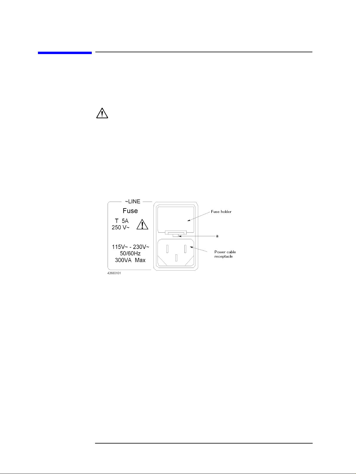
You can check and replace the fuse by dismounting the fuse folder shown in Figu re 1- 1 . To
dismount the fuse holder, first disconnect the power cable, then use a flat-blade
screwdriver or similar tool to push the por tio n mar ked “a” in Figu re 1 -1 upward so that the
holder surface rises up a little, and finally pull off the holder.
Figure 1-1 Fuse holder and power inlet
Power Source Requirements
The Agilent 4294A requires a power source that meets the following specifications. Voltage: 90 to 132 Vac or 198 to 264 Vac (auto select) Frequency: 47 to 63 Hz Power consumption: 300 VA (max)
20 Chapter 1
Page 21

Installation
Power Cable
Power Cable
In accordance with international safety standards, the Agilent 4294A uses a three-wire
power cable. When connected to an appropriate ac power outlet, this cable grounds the
instrument frame through one of the three wires.
The type of power cable shipped with each instrument depends on the country of
destination. Refer to Figure 1-2 for the part numbers of the power cables available.
WARNING For protection against electrical shock, the power cable grounding prong must not be
removed.
The power plug must be plugged into an outlet that provides an appropriate
receptacle for the ground connection.
Chapter 1 21
Page 22

Installation
Power Cable
Figure 1-2 Alternative Power Cable Options
22 Chapter 1
Page 23

Connecting the BNC Adapter (for Option 1D5 Only)
Connecting the BNC Adapter (for Option 1D5 Only)
When Option 1D5 is installed, connect the BNC cable that comes with this option between
the REF OVEN and EXT REF INPUT connectors on the rear panel of the Agilent 4294A.
Option 1D5 makes the frequency of the Agilent 4294A’s test signal both more stable and
more accurate.
Figure 1-3 Connecting the BNC Adapter (for Option 1D5 Only)
Installation
Chapter 1 23
Page 24

Installation
Using the LAN Port
Using the LAN Port
You can connect the Agilent 4294A to a local area network by using the RJ-45J UTP
(Unshielded Twisted Pair) LAN connector provided on the rear panel.
Step 1. To connect the 4294A to a LAN, securely insert the LAN cable into the LAN port.
Step 2. For the 4294A to communicate over a LAN, you must set up the network connection as
described in the section “Using LAN” in the “Programming Manual.”
Figure 1-4 Using the LAN Port
24 Chapter 1
Page 25

Installation
Connecting the Supplied Keyboard
Connecting the Supplied Keyboard
Step 1. Insert the cable of the supplied Mini-D IN keyboard into the key board connector on the rear
panel.
Step 2. Set the keyboard in a comfortable position.
NOTE Do not put anything on the keyboard. Doing so can cause an error during the power-on
self-test.
Figure 1-5 Connecting the Supplied Keyboard
1
1. The Agilent 4294A does not co me with a keyboard if it is purchased with Option 1A 2 (without keyboard) .
Chapter 1 25
Page 26

Installation
Using a Rackmount Kit
Using a Rackmount Kit
If you want to combine the Agilent 4294A with other instruments and a controller to
assemble a comprehensive measuring system, you can use one of the optional
rackmount/handle kits to install it in an efficient way. Figure 1-6 shows how to install the
rackmount kit.
Table 1-2 Rackmount/Handle Kits
Option ID Description Agilent part number
1CN Handle Kit 5062-3991
1CM Rackmount Kit 5062-3979
1CP Rackmount & Handle Kit 5062-3985
Figure 1-6 Installing the Rackmount/Handle Kit
Option 1CN Handle Kit
Option 1CN includes a pair of handles and the parts necessary for attaching the handles to
the Agilent 4294A.
Installing the Handles
Step 1. Remove the adhesive-backed trim strips (1) from the left and right side faces of the front
panel frame (Figure 1-6).
Step 2. Attach the front handles (3) to the side faces with the supplied screws.
26 Chapter 1
Page 27

Installation
Using a Rackmount Kit
Step 3. Attach the trim strips (4) to the handles.
Option 1CM Rackmount Kit
Option 1CM includes a pair of flanges and the parts necessary for attaching them to the
Agilent 4294A. With this option, you can mount the 4294A on an equipment rack with
482.6 mm (19 inch) horizontal spacing.
Mounting the Agilent 4294A on a Rack
Step 1. Remove the adhesive-backed trim strips (1) from the left and right side faces of the front
panel frame (Figure 1-6 on page 26).
Step 2. Attach the flanges (2) to the side faces with the supplied screws.
Step 3. Remove all four legs from the bottom face by pulling up the tabs and slidin g the legs out in
the direction indicated by the arrows.
Step 4. Mount the 4294A on the rack.
Option 1CP Rackmount & Handle Kit
Option 1CP includes two flanges and two handles along with their attachments.
Mounting the Agilent 4294A on a Rack (w ith Handles)
Step 1. Remove the adhesive-backed trim strips (1) from the left and right side faces of the front
panel frame (Figure 1-6 on page 26).
Step 2. Attach the handles (3) and flanges (5) to the side faces with the supplied screws.
Step 3. Remove all four legs from the bottom face by pulling up the tabs and slidin g the legs out in
the direction indicated by the arrows.
Step 4. Mount the 4294A on the rack.
Chapter 1 27
Page 28

Installation
Environmental Requirements
Environmental Requirements
The Agilent 4294A is designed to operate under the following environmental conditions
(with the floppy disk drive operational). For more information, refer to Chapter 10 ,
“Specifications and Supplemental Performance Characteristics,” on page 313.
T emp erature: 10°C to 40°C Humidity: 15% to 80% (relative humidity)
NOTE The Agilent 4294A must be protected from temperature extremes that could cause
condensation within the instrument.
Ventilation Requirements
To ensure adequate ventilation , make su re that th ere is adequ ate clearance of at least
180 mm behind the unit and 60 mm at each side.
Instructions for Cleaning
To prevent electrical shock, disconnect the Agilent 4294A's power cable from the power
outlet before cleaning.
To clean the exterior of the Agilent 4294A, gently wipe the surfaces with a dry cloth or a
soft cloth that is soaked with water and wrung tightly. Do not attempt to clean the 4294A
internally.
28 Chapter 1
Page 29

2 Learning Operation Basics
This chapter guides you through a tour of the basic measurement functions of the Agilent
4294A Precision Impedance Analyzer. If you are new to the Agilent 4294A, this tutorial
should help you get familiar with the instrument.
29
Page 30

Learning Operation Basics
Required Equipment
Required Equipment
To perform all of the steps in this tour, you must have the following equipment:
• Agilent 4294A Precision Impedance Analyzer (1 unit)
• 16047E Text Fixture for Lead Components (1 piece)
• DUT: Capacitor with lead wires having self-reson ance frequency of 100 MHz or lower ,
such as a 0.1 µF ceramic capacitor (1 piece)
Figure 2-1 Required Equipment
30 Chapter 2
Page 31

Learning Operation Basics
Preparing for a Measurement
Preparing for a Measurement
Prepare the Agilent 4294A for measurement by taking the following steps. This procedure
assumes that the Agilent 4294A has been correctly installed and set up as described in
Chapter 1 , “Installatio n,” on page 17.
Connect the Agilent 16047E Test Fixture
Connect the Agilent 4294A to the Agilent 16047E Test Fixture for Lead Components.
Step 1. Attach the 16047E test fixture to the test connector s on the front panel of the Agilent
4294A by gradually coupling the four BNC connectors and fastening screws of the fixture
with the test connectors and accessory mounting holes of the instrument until they are in
complete contact.
Step 2. Fasten two of the four BNC connectors to the corresponding test connectors by gradually
turning the BNC connectors' rotation levers until each pair of connectors is securely
connected. Be sure to align the grooves on both sides.
Step 3. Simultaneously turn the fixture's two fastening screws clockwise so that the fixture is
secured to the instrument.
Step 4. Finally, secure the remaining two BNC connectors of the fixture by turning their rotation
levers clockwise.
Figure 2-2 Connecting the Agilent 16047E Test Fixture
NOTE Reverse the above procedure when removing the Agilent 16047E Test Fixture.
Chapter 2 31
Page 32

Learning Operation Basics
Preparing for a Measurement
Turn ON the Power
Press the power switch to turn on the power to the Agilent 4294A.
The Agilent 4294A performs a power-on self-test. During the self-test, the model name,
firmware revision numb e r/dat e, options, copyright notice, and other i nf ormati on ap pear on
the LCD. When the self-test is completed, the measurement screen appears on the LCD.
Set the Adapter Type to “NONE”
Use the keystroke sequence [Cal] - ADAPTER [ ] - NONE to configure the Agilent 4294A to operate without an adapter .
This option must be selected when the Agilent 4294A is connected to a direct-coupling
type test fixture such as the Agilent 16047E. With the adapter type set to “NONE,” the
Instrument Status area on the measurement screen does not display the “EX1,” “EX2,”
“7mm,” and “PRB” indicators.
NOTE When you use the Agilent 4294A for actual applications, you may want to use an adapter
such as a 7-mm conversion adapter (terminal adapter), cable, or probe. To do so, you must
specify the appropriate adapter type and then perform a calibration procedure called
“Adapter Setup,” in which you calibrate the Agilent 4294A for the connected adapter by
measuring a specific calibration standard. However, because this example uses the Agilent
16047E, which is a direct-coupling fixture that does not require an adapter, you need not
perform the “Adapter Setup” procedure in this t our.
For the Agilent 4294A to perform measurement, you must select the appropriate
adapter type option. Whenever you start a new measurement session, you should
check the indicator (“EX1,” “EX2,” “7mm,” “PRB,” or blank) shown in the
Instrument Status area to confirm that the correct adapter type is selected. Do not
forget to check the adapter type, particularly if you frequently reconnect the Agilent
4294A to a number of alternative adapters (including a 7-mm conversion adapter,
probe, cable, test fixture, and so on).
32 Chapter 2
Page 33

Learning Operation Basics
Specifying Measurement Conditions
Specifying Measurement Conditions
Next, you need to specify how your Agilent 4294A should perform measurement.
NOTE Through this procedure, you will configure parameters that apply to both Traces A and B.
You can set each parameter without specifying the active trace or checking its current
setting.
Initialize the Agilent 4294A to the Preset State
Press the [Preset] key to initialize the Agilent 4294A. This puts the Agilent 4294A into its preset state.
NOTE If you turn on the Agilent 4294A wit h a power - on setti ng fil e residi ng on the flas h memor y
(nonvolatile memory disk) or on a floppy disk inserted in the floppy disk drive, the file is
automatically loaded, and the settings contained in the file are restored. Initializing the
Agilent 4294A to its preset state ensures that no specific settings are inherited from the last
measurement session. Therefore, you should initialize the Agilent 4294A by pressing the
[Preset] key whenever you are configuring it for a new measuremen t session, regardless of
whether you turned the instrument off and back on after the previous session.
Note that initializing the Agilent 4294A with the
adapter the instrument is configured to use. Once you have set the adapter type, the setting
is retained until you select another adapter type.
[Preset] key does not affect which type of
Select |Z|-θ as the Measurement Parameter
To select the measurement parameter, follow these steps:
Step 1. Press the
Step 2. Make sure that the
With the
reflects the impedance phase.
[Meas] key to display the Measurement Parameter menu.
|Z|-θ key is selected (this key is selected by default in the preset state).
|Z|-θ key selected, Trace A reflects the absolute impedance value while Trace B
Select Frequency as the Sweep Parameter
Step 1. Press the [Sweep] key to display t he Sweep menu .
Step 2. Check the PARAMETER [ ] s oftkey label to confirm that “FREQ” (frequency sweep) is
shown between the brackets
NOTE The Sweep Parameter menu, which is not used in this tour, allows you to change the s weep
parameter. You can access this menu by pressing the PARAMETER [ ] key.
[ ] (this setting is selected by default in the preset state).
Select Logarithmic Sweep as the Sweep Type
Step 1. From the Sweep menu, select TYPE [ ] to display the Sweep Type menu.
Chapter 2 33
Page 34

Learning Operation Basics
Specifying Measurement Conditions
Step 2. Press the LOG key to select Log (logarithmic) sweep.
Set the Sweep Start Value to 100 Hz
Step 1. Press the [Start] key. The current setting of the sweep start value appears in the Parameter
Setting field in the upper-left area of the screen.
Step 2. Type “100” into the Parameter Setting field using th ese ENTRY block keys:
Step 3. Specify that the value does not take any un it by pres sing the
This puts your entry into effect.
[×1] key in the ENTRY block.
[1][0][0].
Set the Sweep Stop Value to 100 MHz
Step 1. Press the [Stop] key. The current setting of the sweep stop value appears in the
Measurement Parameter field in the upper-left area of the screen.
Step 2. Type “100” into the Parameter Setting field using th ese ENTRY block keys:
Step 3. Suffix your entry with “M” (mega) by pressing the [M/m] key in the ENTRY block. This
puts your entry into effect.
[1][0][0].
Set the Measurement Bandwidth to 2
Step 1. Press the [Bw/Avg] key to display the Measurement Bandwidth/Averaging menu.
Step 2. Press the BANDWIDTH [ ] key to display the Measurement Bandwidth Setting menu.
Step 3. Set the measurement bandwidth to 2 by pressing the
2 key.
34 Chapter 2
Page 35

Learning Operation Basics
Fixture Compensation
Fixture Compensation
Next, you need to eliminate errors produced between the test fixture and the Agilent
4294A. This process is called “fixture compensation.” You can perform the process using
three compensation functions: OPEN, SHORT, and LOAD.
NOTE All calibration settings, including thos e established through fixture compensation, are
applied to both Traces A and B. You can execute each compensation function without
specifying the active trace or checking the current state.
Perform Fixture Compensation for the Open Circuit State
Step 1. Press the [Cal] key to display the Calibration menu.
Step 2. Press the
Step 3. Make sure that the two test electrodes, HIGH and LOW, of the connected text fixture
(Agilent 16047E) are open. Be sure to fix the two electrodes in position by turning
clockwise the fixture’s two electrode fastening screws.
Step 4. Press the
measuring the compensation data, a message “WAIT--MEASURING STANDARD” is
displayed in the Parameter Setting field in the upper-left area of the screen. Upon
completion of measurement, the
indicating that the OPEN compensation function is turned on.
FIXTURE COMPEN key to displa y t he Fixture Com pensation me nu.
OPEN key to measure the OPEN compensation data. While the instrument is
OPEN on OFF softkey label changes to OPEN ON off,
Perform Fixture Compensation for the Short Circuit State
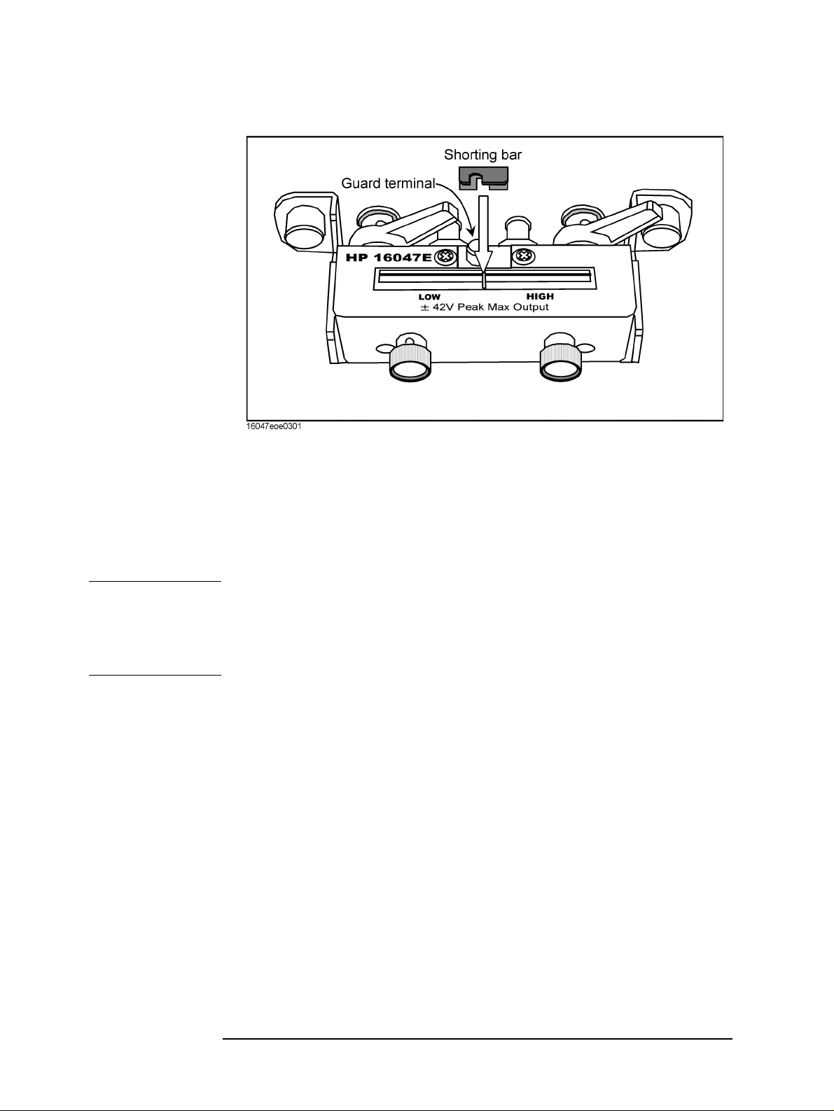
Step 1. Remove the short bar (a metal plate for SHORT compensation) from the upper part of the
Agilent 16047E by loosing the screws and then fit the short bar between the HIGH and
LOW terminals of the Agilent 16047E. Secure the short bar with the two electrode
fastening screws (Figure 2-3 on page 36).
Chapter 2 35
Page 36
Learning Operation Basics
Fixture Compensation
Figure 2-3 Setting Up the Test Circuit for SHORT Compensation
Step 2. Press the
SHORT key to measure the SHORT compensation data. While the instrument is
measuring the compensation data, a message “WAIT--MEASURING STANDARD” is
displayed in the Parameter Setting field in the upper-left area of the screen. Upon
completion of measurement, the
SHORT on OFF softkey label changes to SHORT ON off,
indicating that the SHORT compensation function is turned on.
Step 3. Remove the short bar from the Agilent 16047E's test electrodes.
NOTE The Agilent 4294A provides three fixture compensation functions: OPEN, SHORT, and
LOAD. You can turn on/off each of these compensation functions individually and use
them in any combination to perform the fixture compensation process. In typical
measurement use, it is recommended that you execute the OPEN and SHORT
compensation functions.
36 Chapter 2
Page 37

Carrying Out Measurement and Viewing Results
Connect the DUT
Step 1. Increase the distance between the HIGH and LOW electrodes of the Agilent 16047E by
turning their fastening screws counterclockwise.
Step 2. Fit the DUT's lead wires between the HIGH and LOW electrodes.
Step 3. Turn the fastening screws of the HIGH and LOW electrodes to secure the DUT's lead
wires.
Figure 2-4 Connecting the DUT
Learning Operation Basics
Carrying Out Measurement and Viewing Results
Chapter 2 37
Page 38

Learning Operation Basics
Carrying Out Measurement and Viewing Results
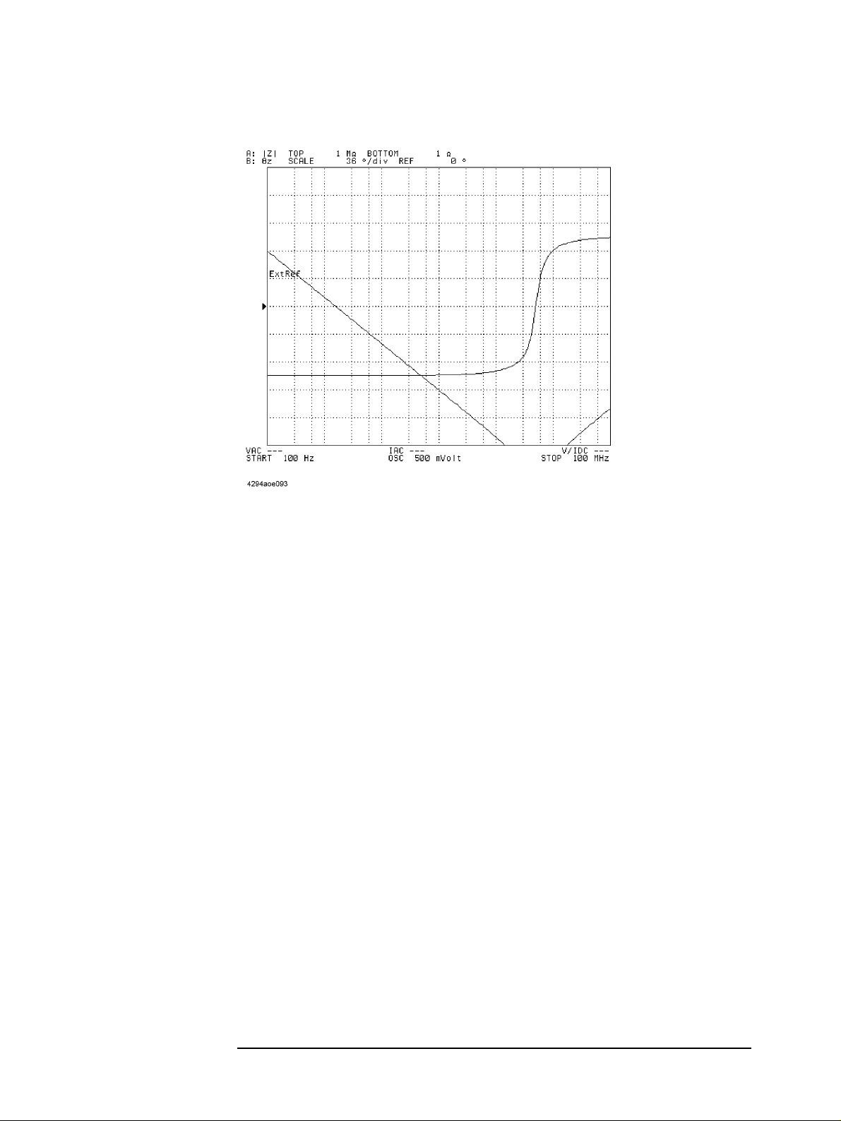
Figure 2-5 Measurement results displayed just after connecting the DUT
Apply the Logarithmic Format to the Vertical Axis for |Z|
Step 1. Make sure that Trace A is selected as the active trace (Trace A is active by default in the
preset state).
Step 2. Press the
Step 3. Press the LOG key to make the graph's vertical axis logarithmic.
[Format] key to display the Display Format menu.
Apply the Linear Format to the Vertical Axis for θ
Step 1. Press the [B] key to activate Trace B.
Step 2. Make sure that the graph's vertical axis is in the linear format with the
(this setting is selected by default in the preset state).
LIN key selected
38 Chapter 2
Page 39
Carrying Out Measurement and Viewing Results
Figure 2-6 Result of Applying the Logarithmic Format to the Graph
Learning Operation Basics
Display the Measured |Z| and θ Values in Parallel
Step 1. Press the [Display] key to display the Display menu.
Step 2. Press the
should change to
SPLIT on OFF key to split the screen into upper and lower halves (the key label
SPLIT ON off).
Chapter 2 39
Page 40
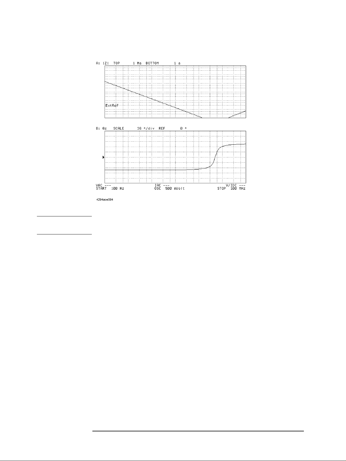
Learning Operation Basics
Carrying Out Measurement and Viewing Results
Figure 2-7 Displaying Traces A and B in Parallel
NOTE You do not need to check which trace is active when you split the screen because this
setting is applied to both Traces A and B.
Auto-scale the |Z| Trace
Step 1. Press the [A] key to activate Trace A.
Step 2. Press the
Step 3. Press the
[Scale Ref] key to display the Scale Reference menu.
AUTO SCALE key to auto-scale the trace for |Z|.
Auto-scale the θ Trace
Step 1. Press the [B] key to activate Trace B.
Step 2. Press the AUTO SCALE key to auto-scale the trace for θ.
40 Chapter 2
Page 41
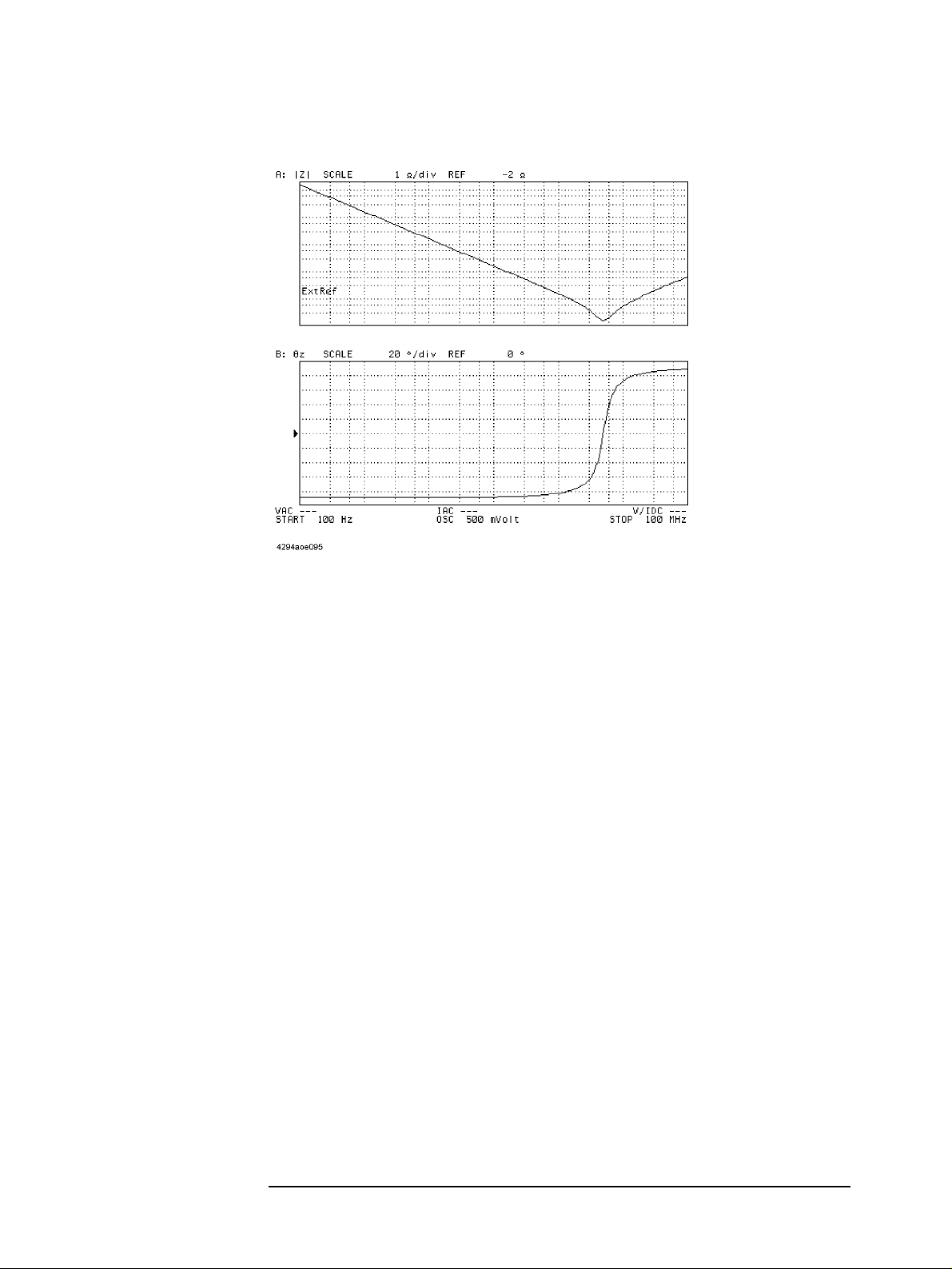
Figure 2-8 Results of Auto-scaling
Learning Operation Basics
Carrying Out Measurement and Viewing Results
Chapter 2 41
Page 42

Learning Operation Basics
Results of Analysis
Results of Analysis
Determine the Self-resonance Frequency and Resonant Impedance
Step 1. Press the [A] key to activate Trace A.
Step 2. Press the
identified by number 0) appears in the center of the graph.
Step 3. Press the
should change to
performs a search action upon completion of each sweep cycle.
Step 4. Press the
tracking function is enabled, the instrument detects and moves the main marker to the
minimum |Z| value each time it has completed one sweep cycle.
You can determine the self-resonance frequency and resonant impedance by reading the
sweep parameter (frequency) and measurement parameter values indicated by the main
marker that appears in the upper-left area of the graph for Trace A. In the example shown
in Figure 2-9, the DUT exhibits its self-resonance frequency and resonant impedance at
approximately 5.13 MHz and 155 mΩ, respectively.
Figure 2-9 Result of Searching for the Self-Resonance Frequency (with the Search Tracking
Function On)
[Search] key to display the Search menu. The main marker (a trace marker
SEARCH TRK on OFF key to turn on the search tracking function (the key label
SEARCH TRK ON off). When this function is enabled, the instrument
MIN key to move the main marker to the minimum |Z| value. Since the search
42 Chapter 2
Page 43

3 Front/Rear Panel and LCD Display
This chapter covers the features of the front and rear panels of the Agilent 4294A. It
contains illustrations and descriptions of the front panel features, the LCD display and its
labels, and the rear panel connectors.
43
Page 44
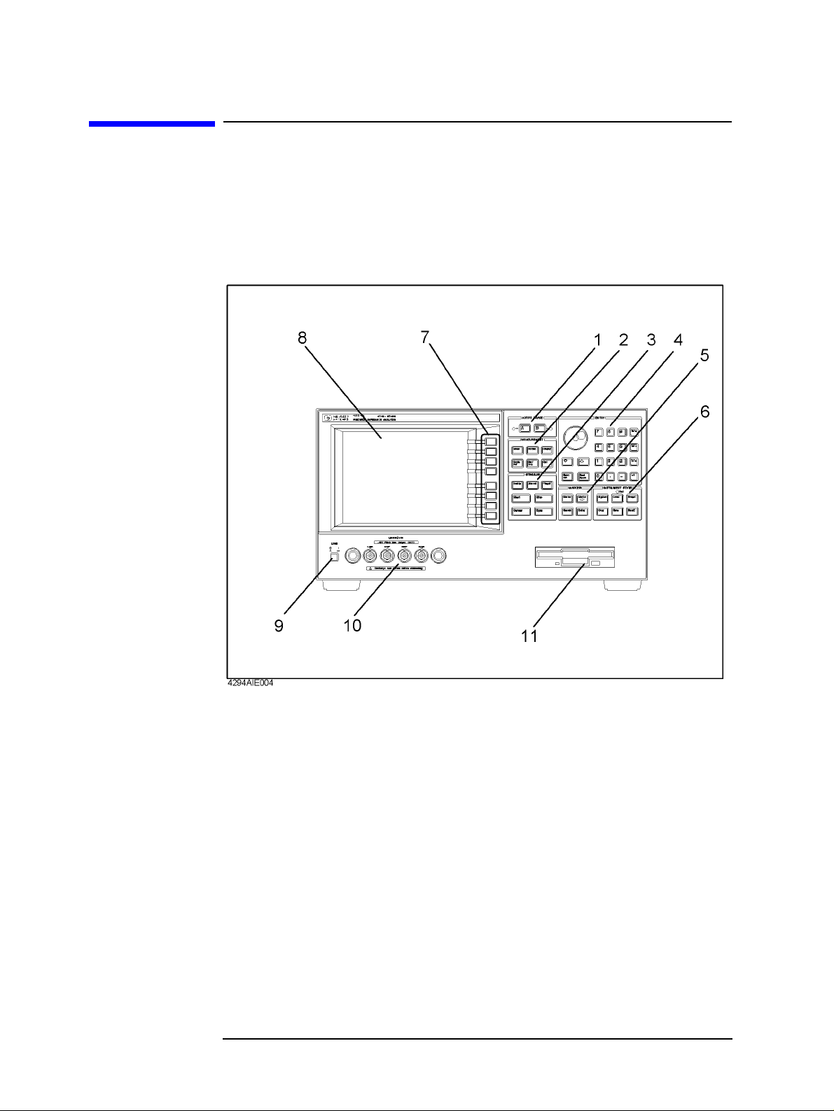
Front/Rear Panel and LCD Display
Front Panel
Front Panel
The front panel of the Agilent 4294A provides several blocks of hardkeys and an LCD
display with a series of softkeys along its right-hand edge. Also, there are a number of test
connectors and a power switch beneath the LCD display. Figure 3-1 shows the front panel
of the Agilent 4294A.
Figure 3-1 Front Panel of the Agilent 4294A
Hardkeys
The hardkeys are 46 physical keys located on the upper-right part of the front panel; they
are divided into six functionally classified blocks (#1 to #6 in Figure 3-1). Each hardkey is
labeled with text that describes its function. The eight keys laid out vertically along the
right-hand edge of the LCD display are called “softkeys” to distinguish them from the
hardkeys. Note that the term “hardkey” refers to all of the controls within each of the six
key blocks, including the circular-shaped rotary knob (❍) in the Entry block.
A hardkey either directly controls the functions of the Agilent 4294A, provides access to
softkey menus, or both.
44 Chapter 3
Page 45

Front/Rear Panel and LCD Display
Front Panel
NOTE As a typographic convention to distingu ish between hardkeys and softkeys, th is
manual uses a pair of brackets (
[ ]) to enclose hardkey labels while showing softkey
labels without enclosing them.
[Hardkey] key Indicates a hardkey labeled “Hardkey.” Softkey key Indicates a softkey labeled “Softkey.”
Note that descriptive text in this manual sometimes only indicates key labels without
following them by the word “key.”
When several keys are separated by a hyphen (-), pr ess them in the sequence indicated. For
example, you should use the keystroke sequence
[Scale Ref] - AUTO SCALE to enable
automatic scale adjustment. As an exception, numeric keys may appear without a hyphen
in between; for example, the keystroke sequence to enter a value of 100 may be expressed
as [1][0][0].
1. ACTIVE TRACE block
With the Agilent 4294A, you can v iew two traces (waveforms) for each s weep cycle: T race
A and Trace B. Some parameters, such as the sweep range, apply to both traces, while
other parameters can be separately configured for each trace. You can use the
in the Active Trace block to choose between Traces A and B. Once you have activated
either trace, you can configure measurement conditions and perform analysis on that
“active” trace. When you set measurement conditions, be aware of which trace is currently
active.
[A] or [B] key
[A] key Activates Trace A so you can set conditions and perform
analysis on Trace A.
[B] key Activates Trace B so you can set conditions and perform
analysis on Trace B.
2. MEASUREMENT Block
This block provides keys for configuring all measurement conditions except the test signal settings.
[Meas] key Provides access to a softkey menu that lets you select
measurement parameters.
[Format] key Provides access to softkey menus that let you select the
data display format (graph axis format) and set up the phase
display unit and phase expansion feature.
[Display] key Provides access to softkey menus that let you configure
general display options ( except the display f ormat and scale
setting) and perform equivalent circuit analysis.
[Scale Ref] key Provides access to a softkey menu that lets you configure
graph scale settings.
Chapter 3 45
Page 46

Front/Rear Panel and LCD Display
Front Panel
[Bw/Avg] key Provides access to a softkey menu that lets you configure
the bandwidth and averaging settings.
[Cal] key Provides access to a softkey menu that lets you set up the
calibration feature.
3. STIMULUS Block
This block provides keys for configuring the test signal parameters.
[Sweep] key Provides access to a softkey menu that lets you configure
the sweep settings for th e t e st signals.
[Source] key Provides access to a softkey menu that lets you configure
the frequency (CW frequency) , test signal level , and dc bias
conditions. When you are setting a sweep parameter, you
can use the
the sweep range.
[Trigger] key Provides access to a softkey menu that lets you set up the
trigger system.
[Start], [Stop], [Center], and [Span] keys to set
[Start] key Lets you specify the value at which to start the sweep.
[Stop] key Lets you specify the value at which to stop (finish) the
sweep.
[Center] key Lets you specify the sweep center value.
[Span] key Lets you specify the sweep span value.
4. ENTRY Block
Provides keys for entering numeric values and text strings. To configure a parameter, first
press the hardkey or softkey associated with the parameter to put the instrument into entry
mode, in which it can accept your entry with the name and current value of the parameter
shown in the upper-left area of the LCD display, and then use these keys to enter the
desired value.
❍
❍ (rotary knob) Y o u can adjust the current sett ing by turning thi s knob. This
❍❍
method immediately updates the parameter value without
requiring you to press a unit key. When working with a
particular configuration item, you can also use the rotary
knob to move the cursor horizontally.
[↑] and [↓] keys
(step keys)
The step keys allow you to increment or decrement the
current setting. This method immediately updates the
parameter value without requiring you to press a unit key.
[Entry Off] key This key switches the instrument from entry mode to
normal operation mode with the name and current setting
of the parameter no longer shown in the upper-left area of
the LCD display.
46 Chapter 3
Page 47

Front/Rear Panel and LCD Display
Front Panel
[Back Space] key Deletes the character to the left of cursor and moves the
cursor back one space. If you make a mistake in entering a
value through numeric keys , you can us e this k ey to correct
your entry.
[0] through [9] keys
(numeric keys) with
[-] keys
[G/n][M/µ][k/m][×1] keys
[.] and
(unit keys)
Use these keys to enter each numeral that makes up your
entry. Finally, press a unit key to put your entered value
into effect.
After entering your desired value through numeric keys,
press one of the unit keys to suffix the value with the
specific unit. Your entered value does not take effect until
you press a unit key. Each unit key, except the [×1] key,
represents two different units, identifying them with their
respective initial letters. Which unit to use is automatically
determined based on the selected parameter. Use the [×1]
key to enter a value that does not take a specific unit.
5. MARKER Block
The MARKER block provides keys for configuring marker settings. A marker is an
inverted triangle (∇) that appears on the measurement trace (waveform). The marker
allows you to read the value of a parameter at a specific point on the trace.
[Marker] key Provides access to a softkey menu that lets you configure
the basic marker settings such as turning on/off the marker
facility.
[Marker→] key Provides access to a softkey menu that lets you assign the
currently marked value to another parameter. From the
softkey menu, for example, you can select the
MKR→START key to use the sweep parameter value at the
current marker position as the value at which to start the
sweep; this way, you can start a new sweep cycle from the
current marker position.
[Search] key Provides access to a softkey menu that lets you activate the
marker search function. The marker search function
automatically moves the marker to a specific position (such
as the maximum value) on the trace so you can check the
value of the parameter at that position.
[Utility] key Provides access to a softkey menu that lets you activate
other marker functions in addition to the marker value
assignment (
[Marker→]) and marker search ([Search])
functions.
6. INSTRUMENT STATE Block
Provides keys for configuring basic instrument settings that are not directly related to
Chapter 3 47
Page 48

Front/Rear Panel and LCD Display
Front Panel
measurement or analysis.
[System] key Provides access to a softkey menu that lets you control and
manage the entire instrument. You can also set up the limit
line test function.
[Local] key Pressing this key switches the Agilent 4294A from remote
mode (in which it is controlled by an external controller) to
local mode (in which it accepts keystrokes from its front
panel). While the instrument is in remote mode, the “Rmt”
LED above this key is lit. This key also provides access to a
softkey menu that lets you configure the GP-IB and LAN
settings.
[Preset] key Initializes the Agilent 4294A to its preset state. No softkey
menu is displayed after you put the instrument into the
preset state by pressing this key, but you can display a
softkey menu by pressing one of the hardkeys associated
with softkey menus.
[Copy] key Provides access to a softkey menu that lets you control how
to output the screen contents to the printer.
[Save] key Provides access to a softkey menu that lets you save such
information as the current settings, measurement data, and
screen contents to the storage device of the Agilent 4294A.
[Recall] key Provides access to a softkey menu that lets you recall (load)
a state file from the storage device of the Agilent 4294A to
restore the settings and measurement data stored in the state
file.
7. Softkeys
The softkeys are eight keys located along the right -hand edg e of the LCD dis play. Pressing
a hardkey displays a menu of labels that define the functions of the softkeys. For more
information on softkey labels, refer to “5. Softkey Label Area” on page 54.
8. Color LCD Display
Displays nearly all information necessary for using the Agilent 4294A, including
measurement results (trace data), instrument status, analysis results, and softkey labels.
9. Power Switch
Turns on/off the power to the instrument. When you turn on the Agilent 4294A, it is
initialized to its power-on defaults, with no softkey menu shown on the screen. From this
state, you can display a softkey menu by pressing a specific hardkey. Note that if you turn
on the instrument with a power-on setting file (AUTOREC.STA) residing on the flash
memory (nonvolatile memory disk) or on a floppy disk inserted in the floppy disk drive,
the file is automatically loaded, and the settings contained in the file are restored.
48 Chapter 3
Page 49

Front/Rear Panel and LCD Display
Front Panel
10. UNKNOWN Terminals
These connectors let you connect the instrument with a device under test (DUT) via test
accessories (such as an adapter, test fixture, or cable). These accessories adopt a
four-terminal pair design, thereby enabling more accurate and wider-range dynamic
measurements. Each test connector has a pair of holes for securing the test accessory to the
instrument.
INSTALLATION CATEGORY I
CAUTION To prevent failure, do not apply dc voltage or current to the UNKNOWN terminal. Special
care must be taken with capacitors since they may be charged. Be sure to connect the DUT
to the UNKNOWN terminal (or test fixture) only after discharging them sufficiently.
11. Built-in 3.5 Inch Floppy Disk Drive
Allows you to store and retrieve such data as measurement data, instrument settings, screen
contents, and HP Instrument BASIC programs. This drive uses a 3.5-inch, MS-DOS format
floppy disk of 1.44 MB capacity.
Chapter 3 49
Page 50

Front/Rear Panel and LCD Display
Rear Panel
Rear Panel
Figure 3-2 Rear Panel
1. External Reference Input Connector
Allows you to connect an external frequency reference signal to the Agilent 4294A so that
its internal signal is phase locked to the external frequency reference signal to achieve a
more accurate frequency.
If Option 1D5 (High Stability Frequency Reference) is installed, connect the supplied
BNC(m)-BNC(m) adapter between this connector and “2. High Stability Frequency
Reference (Option 1D5 Only)”.
When an external frequency reference signal is input to this connector , the Agilent 4294 A's
test signal is automatically phase locked to that reference signal. When the reference signal
stops, the Agilent 4294A will automatically revert to its internal frequency reference
signal.
2. High Stability Frequency Reference (Option 1D5 Only)
This connector is intended for Option 1D5 (High Stability Frequency Reference) to output
the reference signal. If Option 1D5 is installed, connect the supplied BNC(m)-BNC(m)
adapter between this connector and Åu1. External Reference Input ConnectorÅv.
50 Chapter 3
Page 51

Front/Rear Panel and LCD Display
Rear Panel
3. External Trigger Input
Allows you to input a TTL-compatible signal to trigger the execution of measurement.
When the signal shows a rising or falling edge between the LOW and HIGH states, a
measurement cycle is triggered. Before you can trigger measurement by inputting a signal
through this connector, you have to specify that the trigger signal be input fr om an external
trigger source (via the external trigger input). To do so, use the keystrokes:
SOURCE [ ] - EXTERNAL. For more information on the input signal conditions specific to
this connector, refer to Chapter 10 , “Specifications and Supplemental Performance
Characteristics,” on page 313.
[Trigger] -
4. LAN Port
Allows you to connect the Agilent 4294A with a local area network (LAN). The “Tx”
(transmit) LED located on the right-hand side of the LAN port is lit while the Agilent
4294A is outputting data over the local area network. For more information on working
with a local area network, refer to the Programming Manual.
5. Internal Reference Output
Connects to the external reference input terminal of another instrument to phase lock it to
the Agilent 4294A.
6. External Program RUN/CONT Input
Allows you to input a TTL-compatible signal that triggers the RUN or CONTINUE
command for an HP Instru ment BASIC program . Wh en the sign al show s a ri sing or f allin g
edge between the LOW and HIGH states, then the command is triggered. For more
information on the input signal conditions specific to this connector, refer to Chapter 10 ,
“Specifications and Supplemental Performance Characteristics,” on page 313.
7. 8-bit I/O Port
Provides a data communications interface with an external device such as a handler on a
production line. This port supports 4-bit data for input and 8-bit data for output.
8. Time Base Adjuster (for Option 1D5)
This adjuster is used to fine-tune the operating frequency of the Agilent 4294A when it is
equipped with Option 1D5 (High Stability Frequency Reference).
NOTE This is intended for service center use only. Do not attempt to adjust the operating
frequency yourself.
9. Mini-DIN Keyboard Port
A PS/2 port intended for connecting a 101-key English keyboard. You can use a keyboard
to facilitate entry operations such as creating and executing HP Instrument Basic programs
or entering display titles.
NOTE This port only supports a 10 1-k ey English keyboard with a PS/2 connect or. Do not attempt
Chapter 3 51
Page 52

Front/Rear Panel and LCD Display
Rear Panel
to use an unsupported keyboard.
10. 24-bit I/O Port
Provides a data communications interface with an external device such as a handler on a
production line. This port supports 8-bit data for input/output and 16-bit data for output.
11. Printer Port
A parallel port that connects to a printer . Connecting a suppor ted printer allows you to print
out such data as measurement graphs and lists of measured values or settings. For a list of
supported printers, refer to “Print the measurement results and internal data with a printer”
on page 281.
12. External Monitor Terminal
Connects to an external color monitor. An external color monitor connected to this term inal
can display the same information as the Agilent 4294A's built-in LCD.
13. GPIB Connector
Allows you to connect the Agilent 4294A to any external controller or instrument that
supports GPIB (General Purpose Interface Bus). GPIB is useful when you want to
assemble an automatic measurement system by having the Agilent 4294A interact with a
controller and other instruments. For information on using GPIB to perform automatic
measurement, refer to “Programming Guide.”
14. Inlet (with a fuse box)
T o use the Agilent 4294A, you must connect this inlet with the three-wire power cable that
comes with the Agilent 4294A. For more information, refer to Chapter 1, “Installation and
Setup.”
52 Chapter 3
Page 53

Front/Rear Panel and LCD Display
Items Displayed on the LCD
Items Displayed on the LCD
Figure 3-3 Items displayed on the LCD (with split display mode off and full-screen mode on)
1. Measurement Parameter Fields
Each of these fields show the currently selected measurement parameters for either Trace A or B.
2. Scale/Reference Fields
These fields show the current scale settings for Traces A and B.
3. Marker Measurement Parameter Value Fields
These fields show the measurement parameter values that correspond to the current marker
position for Traces A and B.
4. Menu Title Field
This field shows the name of the current softkey menu, which consists of up to 8 softkey labels.
Chapter 3 53
Page 54

Front/Rear Panel and LCD Display
Items Displayed on the LCD
5. Softkey Label Area
Shows the labels that are, in the current context, associated with the softkeys on the
right-hand side. Table 3-1 lists the types of softkey options and their functions.
Table 3-1 Types of softkey options and their functions
Type of softkey option Function
Two or more softkey
labels joined with vertical
bars (
|)
Softkey label immediately
followed by a “➤” symbol
Softkey label followed by
ON off” or “on OFF”
“
You can select one of these options. The currently selected
softkey label is underlined.
Pressing the softkey displays a softkey sub-menu
associated with a specific function.
Pressing the corresponding softkey turns on/off the
function in a toggle fashion. The softkey label is followed
by “
ON off” when the function is on and “on OFF” when
the function is off.
Softkey label immediately
followed by “
[ ].”
The brackets (
setting of the associated function. If the function has two
[ ]) enclose text that describes the current
alternative settings, pressing the softkey toggles between
the settings. If the function has three or more alternative
settings, the label is usually followed by “➤,” and pressing
the softkey displays a softkey sub-menu for selecting one
of those settings.
more n/m This softkey label indicates that the softkey menu consists
of
m pages, and that the nth page of the menu is currently
displayed. You can use the
more n/m key to move to the
next page of the softkey menu (or to the first page if the
current page is the last one).
return This softkey label is contained in a softkey sub-menu that is
displayed when you press a softkey followed by “➤.” You
can press the corresponding softkey to return to the main
menu, that is, the original softkey menu that had been
displayed before you accessed the current menu, as long as
the current menu is a sub-menu.
done Select this softkey label to put your entry into effect and
return to the main menu.
yes This softkey label appears when you are prompted to
confirm yo ur entry before applying it. Pressing the
corresponding softkey puts your entry into effect.
cancel Select this softkey label to cancel your entry and return to
the main menu.
54 Chapter 3
Page 55

Table 3-1 Types of softkey options and their functions
Type of softkey option Function
Front/Rear Panel and LCD Display
Items Displayed on the LCD
Softkey label for setting a
parameter
1
Pressing the corresponding softkey displays the function's
current setting in the Parameter Setting field in the
upper-left part of the screen and allows you to change the
current setting with the Entry block keys (for example,
[Bw/Avg] - AVERATING FACTOR).
Softkey label for
executing a function
1
Pressing the corresponding softkey immediately executes
the associated function (for example,
MKR→START).
[Marker] -
1. These softkey labels are displayed without any special symbol.
NOTE Some softkey labels combine two or more of the functions shown in Table 3-1. For
example, the
[Sweep] - EDIT LIST, both turns on “sweep list edit mode” and displays a softkey
EDIT LIST key, which can be accessed through the keystroke sequence
sub-menu for editing the list.
Some of the softkey labels currently displayed may not be available depending on the
current context; such softkey labels are dimmed by displaying them at a lower contrast than
the other labels. When you choose the appropriate context by using another key, those
softkey labels will revert to the normal contrast and become available.
6. Sweep Parameter Reading Fields
These fields show the sweep parameter values that correspond to the current marker
position for Traces A and B.
7. Marker Status Fields
These fields provide textual representation of the current status of the marker facility.
Marker couple mode
Cpl Indicates that the marker facility is currently in couple mode. In this
mode, changes to Traces A and B are synchronized.
Marker search track mode
Max Indicates that the marker facility is currently in search track mode and
configured to detect the maximum value. The main marker moves to
the maximum value on the trace each time one sweep cycle is
completed.
Min Indicates that the marker facility is currently in search track mode and
configured to detect the minimum value. The main marker moves to
the minimum value on the trace each time one sweep cycle is
completed.
Targ Indicates that the marker facility is currently in search track mode and
configured to detect the specified target value. The main marker
moves to the target value on the trace each time one sweep cycle is
Chapter 3 55
Page 56

Front/Rear Panel and LCD Display
Items Displayed on the LCD
completed.
Peak Indicates that the marker facility is currently in search track mode and
configured to detect the peak value. The main marker moves to the
peak value on the trace each time one sweep cycle is completed.
∆ marker mode
∆Mkr Indicates that the marker facility is currently in default ∆ marker
mode. In this mode, the ∆ marker keeps track of changes to the trace,
maintaining the same position in terms of the sweep parameter value.
Fxd∆ Indicates that the marker facility is currently in fixed ∆ marker mode.
In this mode, the ∆ marker is fixed at a certain point on the screen,
without reflecting any changes to the trace. It remains in the same
position in terms of both the sweep parameter and measurement
parameter values.
Trk∆ Indicates that the marker facility is currently in tracking ∆ marker
mode. In this mode, the ∆ marker appears in the same position as, and
moves synchronously with, the main marker,
8. Marker Statistics/Trace Bandwidth Analysis Fields
These fields show the marker statistics (average, standard deviation, and peak-to-peak
values) or the results of trace bandwidth analysis (bandwidth, center value, Q peak, ∆L,
and ∆R) for Traces A and B. When both features are enabled, they display the marker
statistics only.
9. Limit Line Test Fields
These fields show the results of limit line tests as either “PASS” or “FAIL.” By performing
a limit line test, you can determine whether the trace of measurement results falls within
your specified limit line.
10. HP Instrument Basic Status Indicator
Indicates the execution status of HP Instrument BASIC.
* HP Instrument BASIC is currently executing a program or command.
You cannot execute an additional command.
_ HP Instrument BASIC ha s suspen ded the execut ion of a p rog ram. You
can resume the program using the CONTINUE command.
? HP Instrument BASIC is waiting for a keystroke to continue the
execution of a program. You cannot execute an additional command.
(blank) HP Instrument BASIC is not executing a program or command. You
can use commands other than the CONTINUE command.
11. dc Voltage/Current Bias Monitor Field
This field shows the monitor value (voltage or amperage) for the dc bias conditions that are
currently in effect. For this field to actually display the monitor value, you must apply dc
bias through the keystroke sequence
56 Chapter 3
[Source] - BIAS MENU - BIAS on OFF and then turn
Page 57

Front/Rear Panel and LCD Display
Items Displayed on the LCD
on the dc bias monitor feature through the keystroke sequence [Display] - BIAS MON [ ] -
VOLT/CURRENT.
12. Sweep Stop/Span Value Field
This field shows the sweep stop or span value that is currently in ef fect. Use the [Stop] key to set the sweep stop value and the
[Span] key to set the sweep span value.
13. Test Signal Current Level Monitor Field
This field shows the AC current level monitor value for the test signal that is currently in
effect. For this field to actually display the monitor value, you must turn on the test signal
level monitor feature through the keystroke sequence
[Display] - OSC MON on OFF.
14. Test Signal Level/CW Frequency Setting Field
This field shows the test signal level setting for frequency sweep or the CW frequency
setting for test signal level sweep or dc bias sweep. Use the [Source] key to change the
current value.
15. Test Signal Voltage Level Monitor Field
This field shows the AC voltage level monitor value for the test signal that is currently in
effect. For this field to actually display the monitor value, you must turn on the test signal
level monitor feature through the keystroke sequence
[Display] - OSC MON on OFF.
16. Sweep Start/Center Value Field
Shows the start or center value for the sweep settings that are currently in effect. Use the
[Start] key to set the sweep start value and the [Center] key to set the sweep center value.
17. Instrument Status Area
This area shows the status of various functions of the ins trument.
Trace validity
* After you have changed the measurement conditions, this indicator is
displayed until you update the measurement trace with the new
settings. T o get a correct measurement trace, yo u must update the trace
so that this indicator disappears.
dc bias status
DCB Indicates that the instrument is performing measurement under dc
voltage bias conditions (in variable voltage mode) or dc current bias
conditions (in variable current mode).
VC Indicates that the instrument is performing measurement under dc
voltage bias conditions (in constant voltage mode).
IC Indicates that the instrument is performing measurement under dc
current bias conditions (in constant current mode).
Chapter 3 57
Page 58

Front/Rear Panel and LCD Display
Items Displayed on the LCD
V ↓ Indicates that, because you specified dc voltage bias (in constant
voltage mode) with a setting that exceeds the defined voltage limit, the
actual applied voltage differs from the intended setting.
I ↓ Indicates that, because you specified dc current bias (in constant
current mode) with a setting that exceeds the defined curren t limi t, the
actual applied current differs from the intended setting.
(blank) Indicates that dc bias conditions are not applied.
Note that when dc bias conditions are app lied, th e “DC BI AS ON” ind ica tor appear s in th e
lower-right corner of the s creen, regar dless of which bias mode (DC B, VC, IC, V ↓, or I ↓)
is selected.
Adapter type
EX1 Indicates that the instrument is configured to use a 1-meter,
four-terminal pair cable.
EX2 Indicates that the instrument is configured to use a 2-meter,
four-terminal pair cable.
7mm Indicates that the instrument is configured to use the Agilent 42942A
Terminal Adapter (four-terminal pair to 7-mm conversion adapter).
PRB Indicates that the instrument is configured to use the 42941A
Impedance Probe.
(blank) Indicates that the instrument is configured to operate without an
adapter.
User calibration/port extension status
User calibration
feature
CAL ON Fixed Cal ON User-defined POR ON Fixed Por ON User-defined CAP ON ON Fixed CaP ON ON User-defined (blank) (Unknown)
Blank cells in the table indicate that the feature is off.
Port extension
feature
Correction point
setting
58 Chapter 3
Page 59

Fixture compensation status
Front/Rear Panel and LCD Display
Items Displayed on the LCD
Fixture Compensation
Correction point setting
feature
CMP ON Fixed Cmp ON User-defined (blank) (Unknown)
Blank cells in the table indicate that the feature is off.
NOTE The user correction and fixture compensation features share the same correction point
settings. You cannot set correction points specific to a single feature.
Averaging status
Avg Indicates that the sweep-to-sweep averaging feature is on. (blank) Indicates that the sweep-to-sweep averaging feature is off.
Averaging counter
(Positive integer) When the sweep-to-sweep averaging feature is on, this counter
indicates how many times the current trace has been subjected to
sweep-to-sweep averaging. After you have started sweep-to-sweep
averaging, the counter shows “1” upon the 1st sweep cycle, “2” upon
the 2nd cycle, and so on until it reaches the maximum number of
averaging cycles. To view a trace subjected to your specified number
of averaging cycles, you must wait for the instrument to repeat the
sweep cycles until the counter reaches that number.
Data trace definition
D–M Indicates that the currently displayed data trace represents the result of
subtracting the memory trace data from the measurement data.
D/M Indicates that the currently displayed data trace represents the r esult of
dividing the measurement data by the memory trace data.
D%M Indicates that the currently di splayed data trace repr esents the result of
DATA MEM–
the following operation: [%] (where DATA is the
------------------------------------
MEM
100×
measurement data and MEM is the memory trace data).
–O Indicates that the currently displayed data trace represents the result of
subtracting the offset value from the measurement data.
(blank) Indicates that the currently displayed data trace shows the exact
measurement data.
NOTE If “–O” appears below “D–M” or “D%M,” the data trace represents the result of
performing both operations on the measurement data.
Chapter 3 59
Page 60

Front/Rear Panel and LCD Display
Items Displayed on the LCD
Service mode status
Svc Indicates that the instrument is in service mode, which is intended for
servicing use only. The accuracy of data measured in this mode is not
guaranteed. For more information, refer to the “Service Manual.” (blank) Indicates that the instrument is ready for normal measurement use.
Sweep/trigger status
Hld Indicates that the sweep function is in Hold status (i.e., not enabled).
To enable the sweep function, you must select one of the available
sweep modes (single-cycle sweep, group sweep, or continuous sweep).
↓ Indicates that the instrument is performing a sweep cycle. This
indicator appears at the measurement point on the trace 1.5 seconds
after the start of a sweep cycle.
ext Indicates that the instrument is waiting for an external signal that
triggers the start of measurement. This indicator appears after you
have used the keystroke sequence
EXTERNAL to specify that the trigger signal be input from an external
[Trigger] - SOURCE [ ] -
trigger source (via the external trigger input).
man Indicates that the instrument is in manual trigger mode, in which you
can manually start measurement by pressing the
indicator appears after you have u sed the keystroke sequence
-
SOURCE [ ] - MANUAL.
MANUAL key. This
[Trigger]
bus Indicates that the instrument is waiting for a measurement trigger
command to be input through GP-IB or from a LAN. This indicator
appears after you have used the keystroke sequence
SOURCE [ ] - HP-IB/LAN.
[Trigger] -
18. Equivalent Circuit Parameters Field
This field shows the equivalent circuit parameter values after you have used the keystroke sequence
[Display] - more 1/2 - EQUIV CKT - PARAMETERS on OFF. T o use this field to
view the parameter values, you can first either apply the equivalent circuit analysis feature
to calculate the parameter values from the trace representing the mesured frequency
characteristics or enter the equivalent parameter values for simulating frequency
characteristics.
19. External Reference Input Status Field
When a reference signal is input to the external reference input terminal on the rear panel,
this field shows “ExtRef” (even if the instrument is not phase locked). The indicator
disappears when the reference signal stops.
20. Parameter Setting/Instrument Message Field
When you press a key to set a particular parameter (for example, the [Start] to set the sweep start value), this field shows the current setting. When you are changing the current setting, the field also serves as the place to enter the new value through the ENTRY block keys. In addition, an instrument message such as an error mess age may appear in the upper part of this field. For a list of common error messages, Refer to Appendix C , “Error
60 Chapter 3
Page 61

Front/Rear Panel and LCD Display
Items Displayed on the LCD
messages,” on page 417.
21. Title Field
This field provides a place to enter a title (up to 64 alphanumeric characters) that describes
the current screen. To enter the title, use the keystroke sequence
TITLE.
[Display] - more 1/2 -
Chapter 3 61
Page 62

Front/Rear Panel and LCD Display
Items Displayed on the LCD
62 Chapter 3
Page 63

4 Preparation of Measurement Accessories
This chapter describes the required preparation of accessories after finis hing installation of
the Agilent 4294A and before starting measurements. If you have not completed
installation, please refer to Chapter 1 , “Installation,” on page 17 before proceeding to this
chapter.
63
Page 64

Preparation of Measurement Accessories
Selecting Accessories for Measurement
Selecting Accessories for Measurement
Select the appropriate accessories (test fixture, adapter, probe, cable, etc.) for your
measurement in accordance with Table 4-1. Detailed specifications are described in
catalogs or in the operation manual of each accessory.
Table 4-1 Guidelines for Selecting Accessories
Type of
Device
Lead component
Condition Accessory Features of Accesso ry
Entire frequency range of 4294A 16047E Equipped with screws for firm ly
fixing the fixture to the 4294A.
Entire frequency range of 4294A 429 42A and 16092A For both chip and lead
components.
Entire frequency range of 4294A 42942A and 16093A Two binding-post-type
electrodes set 7 mm apart.
Entire frequency range of 4294A 42942A and 16093B Thre e binding-post- type
electrodes set 15 mm and
18 mm apart.
Frequency ≤ 40 MHz 16047C Frequency ≤ 40 MHz 16047D For axial and ra dial lead
components.
Frequency ≤ 13 MHz 16047A For axial and radial lead
components.
Frequency ≤ 10 MHz, Balanced
component and circuit measurement
Frequency ≤ 2 MHz, External dc bias
up to 200 V
16314A Three binding-post-type
electrodes.
16065A For axial and radial lead
components. Equipped with
safety cover.
Frequency ≤ 100 kHz, Component
terminal diameter ≤ 15 mm
Frequency ≤ 100 kHz, Component
terminal diameter ≤ 7.9 mm
Frequency ≤ 100 kHz, Component
terminal diameter ≤ 6 mm
Frequency ≤ 100 kHz, IC pin
diameter ≤ 1 mm
Frequency ≤ 100 kHz 16089D Four alligator clips.
16089A Two Kelvin c lips.
Cable length: approx. 1 m.
16089B Two Kelvin clips.
Cable length: approx. 1 m.
16089E Two Kelvin clips.
Cable length: approx. 1 m.
16089C Two Kelvin clips.
Cable length: approx. 1 m.
Cable length: approx. 1 m.
64 Chapter 4
Page 65

Table 4-1 Guidelines for Selecting Accessories
Prepar ation of Measurement Accessories
Selecting Accessories for Measurement
Type of
Device
Chip component
Condition Accessory Features of Accesso ry
Entire frequenc y range of 4294A,
Component size ≥ 0603
Entire frequenc y range of 4294A,
Component size ≥ 1608
Entire frequenc y range of 4294A,
Component size ≥ 2012
Entire frequenc y range of 4294A,
Component size ≥ 1608
Entire frequenc y range of 4294A,
Component size ≥ 1608
Entire frequency range of 4294A 42942A and 16092A For both chip and lead
Frequency ≤ 40 MHz, Component
size ≥ 1608
Frequency ≤ 15 MHz 16334A Tweezers type.
Frequency ≤ 10 MHz,
Component size ≥ 1608,
Low impedance device
16034G
16034H Can measure arra y- type
components.
42942A and 16191A Connect e d to the component’s
bottom face.
42942A and 16192A Connected to both sides of the
component.
42942A and 16193A Connect e d to the component’s
bottom face.
components.
16034E
Cable length: approx. 1 m.
16044A Connected to the device by four
terminals.
1
Circuit Entire frequency range of 4294A
Solid material
Liquid material
General Cable extension
1. Furnished with the 42941A Impedance Probe Kit.
Permittivity measurement 16451B Cable length: a pprox. 1 m. Permeability measurement 42942A and 16454A
Permittivity measurement
42941A and probe adapter
16048G and 16452A 16048G: approx. 1 m. 16048H and 16452A 16048H: approx. 2 m. 16048G and test fi xture 16048G: approx. 1 m. 16048H and test fi xture 16048H: approx. 2 m. 42942A, coaxial ca ble, and
test fixture
42941A, coaxial ca ble, and
test fixture
Probe type.
42941A: approx. 1.5 m.
NOTE The 16085B Terminal Adapter cannot be used in place of the 42942A Terminal Adapter.
The 16048A BNC 1 m Cable, the 16048B SMC 1 m Cable, the 16048D BNC 2 m Cable,
or the 16048E BNC 4 m Cable cannot be used in place of the 16048G or 16048H.
Chapter 4 65
Page 66

Preparation of Measurement Accessories
Connecting the Accessories
Connecting the Accessories
Step 1. Connect the measurement accessories to the Agilent 4294A.
Step 2. Press the power switch on the front panel of the Agilent 4294A to turn it on.
For more information on connecting accessories to the Agilent 4294A for measurement,
refer to the operation manual furnished with each accessory.
NOTE Whenever you connect accessories to or disconnect accessories from the Agilent 4294A,
you must first turn off the dc bias (Key s trok es:
this step is not taken, the dc bias may destroy the device.
When you connect or disconnect accessories with the Agilent 4294A turned on, error
messages such as “ADC OVERLOAD” or “BRIDGE UNBALANCED” may be displayed
on the LCD. However, this does not cause any special problem. To turn off the message,
press
[Entry Off] key.
The power-on self-test is executed at power-on. If an error is detected in the power-on
self-test, the message “CAUTION: POWER ON TEST FAILED” is displayed in the
upper-left area of the screen. In this case, contact your nearest Agilent Technologies office
or the company from which you purchased this instrument. For more information on the
self-test (self-diagnostic) function, refer to “Performing Self-Diagnosis of the Agilent
4294A” on page 310.
[Source] - BIAS MENU - BIAS ON off). If
66 Chapter 4
Page 67

Prepar ation of Measurement Accessories
Adapter Setting
You must ensure that the adapter setting is properly set after you finish connecting
accessories to the four-terminal pair port of the Agilent 4294A and before you start
measurement. If required, change it to the correct adapter setting. The adapter setting
includes adapter selection and the data acquisition process, which is called adapter setup.
Table 4-2 lists the device connection s and correspo ndin g adapter settings.
Table 4-2 Device Connections and Adapter Settings
Device Connection Accessory
Adapter
Selection
Adapter Setting
Adapter Setup (data measurement)
(√: required; blank: not required)
1
Phase
OPEN SHORT LOAD
A. Connect a direct
connection type test fixtur e
to the four-terminal pair port
of the Agilent
connect the devi ce to the
fixture contacts.
B. Extend the four-termin a l
pair port of the Agilent
4294A with a 1-meter-long
four-t erminal pair
configuration and connect
the device.
C. Extend the four-termin a l
pair port of the Agilent
4294A with a 2-meter-long
four-t erminal pair
configuration and connect
the device.
4294A and
16034E
16034G
16034H
16044A
16047A
16047C
16047D
16047E
2
16065A
2
16089A
2
16089B
2
16089C
2
16089D
2
16089E
16314A
16048G and test fixture
16048G and 16452A
16334A Four-terminal pair,
16451B Fou r-terminal pair,
16048H and test fixture 16048H and 16452A
No Adapter (
Four-terminal pair,
1 meter (
1 meter (
1 meter (
Four-terminal pair,
2 meters (
NONE)
4TP 1M)
4TP 1M)
4TP 1M)
4TP 2M)
√√
√√
√
√√
D. Connect the 42942 A
directly to the four-terminal
pair port of the Agilent
4294A, connect a dedica te d
test fixture to the 7-mm port,
and then connect the device
to the fixture contacts.
42942A and 16092A
42942A and 16093A
42942A and 16093B
42942A and 16191A
42942A and 16192A
42942A and 16193A
42942A and 16454A
42942A Terminal
Adapter (
42942A
7mm
)
√√√√
Chapter 4 67
Page 68

Preparation of Measurement Accessories
Adapter Setting
Table 4-2 Device Connections and Adapter Settings
Device Connection Accessory
Adapter
Selection
Adapter Setup (data measurement)
(√: required; blank: not required)
1
Phase
OPEN SHORT LOAD
E. Connect the 42942A
directly to the four-terminal
pair port of the Agilent
4294A, connect a coaxial
cable to the 7-mm port,
connect a test fixture, and
then connect the device to the
fixture contacts.
F. Connect the 42941A
directly to the four-terminal
pair port of the Agilent
4294A, connect a dedica te d
probe adapter to the 3.5-mm
port, and then connect the
device to the adapte r
contacts.
G. Connect t he 42941A
directly to the four-terminal
pair port of the Agilent
4294A, connect a coaxial
cable to the 3.5-mm port ,
connect a test fixture, and
then connect the device to the
fixture contacts.
42942A, coaxial cable, and test fixture
42941A and probe adapter 42941A Impedance
42941A, coaxial cable, and test fixture
42942A Terminal Adapter
7mm 42942A)
(
Probe
PROBE 42941A)
(
42941A Impedance
PROBE
Probe (
42941A
)
1. Phase compensation.
2. Although it has a cable, it is considered a direct-connection-type test fixture.
√√√√
√√√√
√√√√
Adapter Selection
The adapter selection setting must be confirmed before measurement in accordance with
the connection status of each accessory. If necessary, it must be changed to the correct
setting.
The adapter selection of the Agilent 429 4A can b e co nfirm ed an d, if necessary, changed as follows.
Step 1. Press
Step 2. The adapter selection status is displayed in the [] space of the ADAPTER [ ] key's softkey
[Cal] key to display the Calibration Menu.
label. Proceed to Step 3 if you need to change the selection.
Softkey Label Adapter Selection Status
ADAPTER [NONE] No Adapter ADAPTER [1M] Four-terminal pair, 1 meter ADAPTER [2M] Four-terminal pair, 2 meter ADAPTER [7mm] 42942A Terminal Adapter
68 Chapter 4
Page 69

Prepar ation of Measurement Accessories
Adapter Setting
Softkey Label Adapter Selection Status
ADAPTER [PROBE] 42941A Impedance Probe
NOTE Adapter selection status can also be confirmed through the display of the instrument status
area on the LCD's left side. Refer to “Adapter type” on page 58.
Step 3. Press
ADAPTER [ ] key to display the Adapter Setting Menu.
Step 4. Select the corresponding adapter selection from the following:
Adapter Selection Key Strokes
No Adapter Four-termi n al pair, 1 meter 4TP 1M Four-termi n al pair, 2 meters 4TP 2M 42942A Terminal Adapter 7mm 42942A 42941A Impedance Probe PROBE 42941A
NONE
Adapter Setup
The adapter setup is a process used to acquire the setup data of the adapter selected by the
“Adapter Selection” on page 68. The adapter setup is normally performed in th e following
cases.
• When using the 16048G with the Agilent 4294A for the first time after it is delivered.
• When using the 16048H with the Agilent 4294A for the first time after it is delivered.
• When using the 16334A with the Agilent 4294A for the first time after it is delivered.
• When using the 16451B with the Agilent 4294A for the first time after it is delivered.
• When using the 42942A with the Agilent 4294A for the first time after it is delivered.
• When using the 42941A with the Agilent 4294A for the first time after it is delivered.
• When making a measurement in an ambient temperature that is outside the range of
±5°C from the adapter setup temperature for the above accessories.
NOTE Generally, the adapter setup does not need to be performed except for the above cases.
For each adapter setup procedure, refer to:
• “Adapter Setup Procedure for the 16048G and 16048H” on page 70
• “Adapter Setup Procedure for the 16334A” on page 72
• “Adapter Setup Procedure for the 16451B” on page 73
• “Adapter Setup Procedure for the 42942A” on page 74
• “Adapter Setup Procedure for the 42941A” on page 78
Chapter 4 69
Page 70
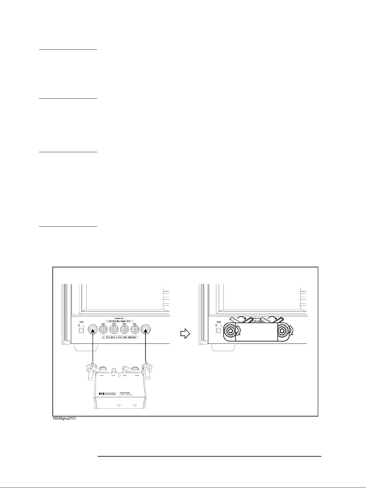
Preparation of Measurement Accessories
Adapter Setting
NOTE When you select “No Adapter” (NONE key) in adapter selection, adapter setup cannot be
performed.
Adapter setup data can be obtained and saved for each adapter selection.
Adapter setting (adapter selection and adapter setup data) is not affected by turning on/off
the Agilent 4294A or by pressing the [Preset] key to initialize the instrument settings.
Adapter Setup Procedure for the 16048G and 16048H
When you use the 16048G 1 m cable or 16048H 2 m cable with another accessory, only
perform the adapter setup for the 16048G or 16048H. The operation manuals of the
16048G and 16048H also describe the adapter setup procedure.
NOTE Adapter setup should be performed at an ambient temperature as close as possible to the
temperature in which the device measurement will actually be made.
If the ambient temperature for your measurement is outside the range of ±5°C from the
adapter setup temperature, it is recommended that you perform adapter setup again at the
appropriate temperature.
It takes a few minutes to complete each setup data measurement.
During each data measurement, the message “WAIT--MEASURING ADJUSTMENT
KIT” is displayed in the instrument state area in the LCD's upper-left side.
Step 1. Make sure that the 16048G or 16048H i s co rrectl y connect ed to th e fou r-terminal pair port
of the Agilent 4294A.
Figure 4-1 Connecting the 16048G or 16048H
70 Chapter 4
Page 71

Prepar ation of Measurement Accessories
Adapter Setting
NOTE The 16048G or 16048H cable must be directly connected to the four-terminal pair port of
the Agilent 4294A. If another accessory like a cable or adapter is inserted between the
16048G or 16048H and the four-terminal pair port of the Agilent 4294A, the correct
adapter setup data cannot be obtained and correct device measurement cannot be
performed after the adapter setup.
Step 2. More than 30 minutes warm-up time is required after turning on the Agilent 4294A.
Step 3. Make the correct adapter selection for the 16048G o r 1604 8H in accorda nce with “Adapt er
Selection” on page 68.
Step 4. After performing Step 4 of “Adapter Selection” on page 68, press the
SETUP key to
display the Adapter Setup Menu.
Step 5. Connect the Lcur and Lpot terminals on the 16048G or 16048H to the Hpot and Hcur
terminals of the 100 Ω Resister (furnished with the Agilent 4294A, Agilent Part Number:
04294-61001) as shown in Figure 4-2. Other terminals should remain open.
Figure 4-2 Connecting 100 Ω Resister (Phase Compensation Data Measurement)
Step 6. Press the
PHASE COMP [-] key to start the phase compensation data measurement.
NOTE The traces on the LCD display do not change during the phase compensation data
measurement.
When the phase compensation data measurement is completed, the softkey label changes
to PHASE COMP [DONE].
Step 7. Connect the Lcur, Lpot, Hpot, and Hcur terminals on the 16048G or 16048H to the Lcur,
Lpot, Hpot and Hcur terminals of the 100 Ω Resister as shown in Figure 4-3.
Chapter 4 71
Page 72

Preparation of Measurement Accessories
Adapter Setting
Figure 4-3 Connecting 100 Ω Resister (Load Data Measurement)
Step 8. Press the
LOAD [-] key to start the load data measurement.
NOTE When the load data measurement is completed, the softkey label changes to
LOAD [DONE].
Step 9. Press the
done key to start calculating the adapter setup data from the measured phase
compensation and load data. The adapter setup data is automatically saved to the EEPROM
(nonvolatile memory) in the Agilent 4294A.
NOTE Press the cancel key to cancel the adapter setup process. If the adapter setup process is
canceled, the previously obtained data is saved as the available adapter setup data.
Adapter Setup Procedure for the 16334A
Perform the adapter setup for the 16334A Tweezers Type Test Fixture in accordance with
the following procedure:
NOTE Adapter setup should be performed at an ambient temperature as close as possible to the
temperature in which the device measurement will actually be made.
If the ambient temperature for your measurement is outside the range of ±5°C from the
adapter setup temperature, it is recommended that you perform adapter setup again at the
appropriate temperature.
It takes a few minutes to complete each setup data measurement.
During each data measurement, the message “WAIT--MEASURING ADJUSTMENT
KIT” is displayed in the instrument state area in the LCD's upper-left side.
Step 1. Make sure that the 16334A is correctly connected to the four-terminal pair port of the
72 Chapter 4
Page 73

Prepar ation of Measurement Accessories
Adapter Setting
Agilent 4294A.
NOTE The 16334A must be directly connected to the four-terminal pair port of the Agilent
4294A. If another accessory su ch as a cable or adapter is inserted between the 16334A and
the four-terminal pair port of the Agilent 4294A, the correct adapter setup data cannot be
obtained and correct device measurement cannot be performed after the adapter setup.
Step 2. More than 30 minutes warm-up time is required after turning on the Agilent 4294A.
Step 3. Make the correct adapter selection for the 16334A in accordance with the “Adapter
Selection” on page 68.
Step 4. After performing Step 4 of the “Adapter Selection” on page 68, press the
SETUP key to
display the Adapter Setup Menu.
Step 5. Put the device contacts of the 16334A into the OPEN condition. Refer to the operation
manual of the 16334A for instructions on switching to the OPEN condition.
Step 6. Press the
PHASE COMP [-] key to start the phase compensation data measurement.
NOTE The traces on the LCD display do not change during the phase compensation data
measurement.
When the phase compensation data measurement is completed, the softkey label changes
to PHASE COMP [DONE].
Step 7. Connect a 100 Ω LOAD device to the 16334A.
Step 8. Press the
LOAD [-] key to start the load data measurement.
NOTE When the load data measurement is completed, the softkey label changes to
LOAD [DONE].
Step 9. Press the
done key to start calculating the adapter setup data from the measured phase
compensation and load data. The adapter setup data is automatically saved to the EEPROM
(nonvolatile memory) in the Agilent 4294A.
NOTE Press the cancel key to cancel the adapter setup process. If the adapter setup process is
canceled, the previously obtained data is saved as the available adapter setup data.
Adapter Setup Procedure for the 16451B
Perform the adapter setup for the 16451B Dielectric Test Fixture in accordance with the
following procedure:
NOTE Adapter setup should be performed at an ambient temperature as close as possible to the
temperature in which the device measurement will actually be made.
If the ambient temperature for your measurement is outside the range of ±5°C from the
adapter setup temperature, it is recommended that you perform adapter setup again at the
appropriate temperature.
It takes a few minutes to complete each setup data measurement.
Chapter 4 73
Page 74

Preparation of Measurement Accessories
Adapter Setting
During each data measurement, the message “WAIT--MEASURING ADJUSTMENT
KIT” is displayed in the instrument state area in the LCD's upper-left side.
Step 1. Make sure that the 16451B is correctly connected to the four-terminal pair port of the
Agilent 4294A.
NOTE The 16451B Dielectric Test Fixture must be directly connected to the four-terminal pair
port of the Agilent 4294A. If another accessory such as a cable or adapter is inserted
between the 16451B and the four-terminal pair port of the Agilent 4294A, the correct
adapter setup data cannot be obtained and correct device measurement cannot be
performed after the adapter setup.
Step 2. More than 30 minutes warm-up time is required after turning on the Agilent 4294A.
Step 3. Make the correct adapter selection for the 16451B in accord ance with “Adap ter Selection”
on page 68.
Step 4. After performing Step 4 of “Adapter Selection” on page 68, press the
SETUP key to
display the Adapter Setup Menu.
Step 5. Put the device contacts of the 16451B into the OPEN condition. Refer to the operation
manual of the 16451B for instructions on switching to the OPEN condition.
Step 6. Press the
PHASE COMP [-] key to start the phase compensation data measurement.
NOTE The traces on the LCD display do not change during the phase compensation data
measurement.
When the phase compensation data measurement is completed, the softkey label changes
to PHASECOMP[DONE].
Step 7. Press
done key to start calculating the adapter setup d ata from the measured load data. Th e
adapter setup data is automatically saved to the EEPROM (nonvolatile memory) in the
Agilent 4294A.
NOTE Press the cancel key to cancel the adapter setup process. If the adapter setup process is
canceled, the previously obtained data is saved as the available adapter setup data.
Adapter Setup Procedure for the 42942A
Perform the adapter setup for the 42942A Terminal Adapter in accordance with the
following procedure (operation manual of the 42942A also describes the adapter setup
procedure).
NOTE Adapter setup should be performed at an ambient temperature as close as possible to the
temperature in which the device measurement will actually be made.
If the ambient temperature for your measurement is outside the range of ±5°C from the
adapter setup temperature, it is recommended that you perform adapter setup again at the
appropriate temperature.
It takes a few minutes to complete each setup data measurement.
During each data measurement, the message “WAIT--MEASURING ADJUSTMENT
74 Chapter 4
Page 75

KIT” is displayed in the instrument state area in the LCD's upper-left side.
Step 1. Make sure that the 42942A is correctly connected to the four-terminal pair port of the
Agilent 4294A.
Figure 4-4 Connecting the 42942A
Prepar ation of Measurement Accessories
Adapter Setting
NOTE The 42942A must be directly connected to the four-terminal pair port of the Agilent
4294A. If another accessory su ch as a cable or adapter is inserted between the 42942A and
the four-terminal pair port of the Agilent 4294A, the correct adapter setup data cannot be
obtained and correct device measurement cannot be performed after the adapter setup.
Step 2. More than 30 minutes warm-up time is required after turning on the Agilent 4294A.
Step 3. Make the correct adapter selection for the 42942A in accordance with “Adapter Selection”
on page 68.
Step 4. After performing Step 4 of “Adapter Selection” on page 68, press the
SETUP key to
display the Adapter Setup Menu.
Step 5. Connect OPEN (0 S) t o the 7-mm port of the 4294 2A (the OP EN standard i s furnis hed with
the 42942A Terminal Adapter).
Chapter 4 75
Page 76
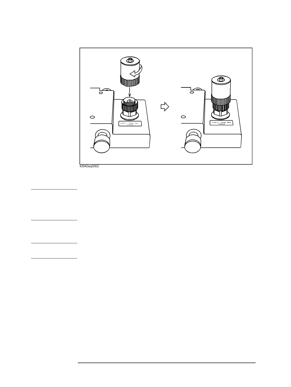
Preparation of Measurement Accessories
Adapter Setting
Figure 4-5 Connecting OPEN (0 S) to the 42942A
Step 6. Press the
PHASE COMP [-] key to start the phase compensation data measurement.
NOTE The traces on the LCD display do not change during the phase compensation data
measurement.
When the phase compensation data measurement is completed, the softkey label changes
to PHASECOMP[DONE].
Step 7. With the OPEN (0 S) standard connected to the 7-mm port, press the
OPEN [-] key to start
the open data measurement.
NOTE When the load data measurement is completed, the softkey label changes to
OPEN [DONE].
Step 8. Remove the OPEN (0 S) standard from the 7-mm port of the 42942A. Then connect the
SHORT (0 Ω) standard to the 7-mm port (the SHORT standard is furnished with the
42942A Terminal Adapter).
76 Chapter 4
Page 77

Figure 4-6 Connecting SHORT (0 Ω) to the 42942A
Prepar ation of Measurement Accessories
Adapter Setting
Step 9. Press the
SHORT [-] key to start the short data measurement.
NOTE When the short data measurement is completed, the softkey label changes to
SHORT [DONE].
Step 10. Remove the SHORT (0 Ω) standard from the 7-mm port of the 42942A. Then connect the
LOAD (50 Ω) standard to the 7-mm port (the LOAD standard is furnished with the
42942A Terminal Adapter).
Chapter 4 77
Page 78
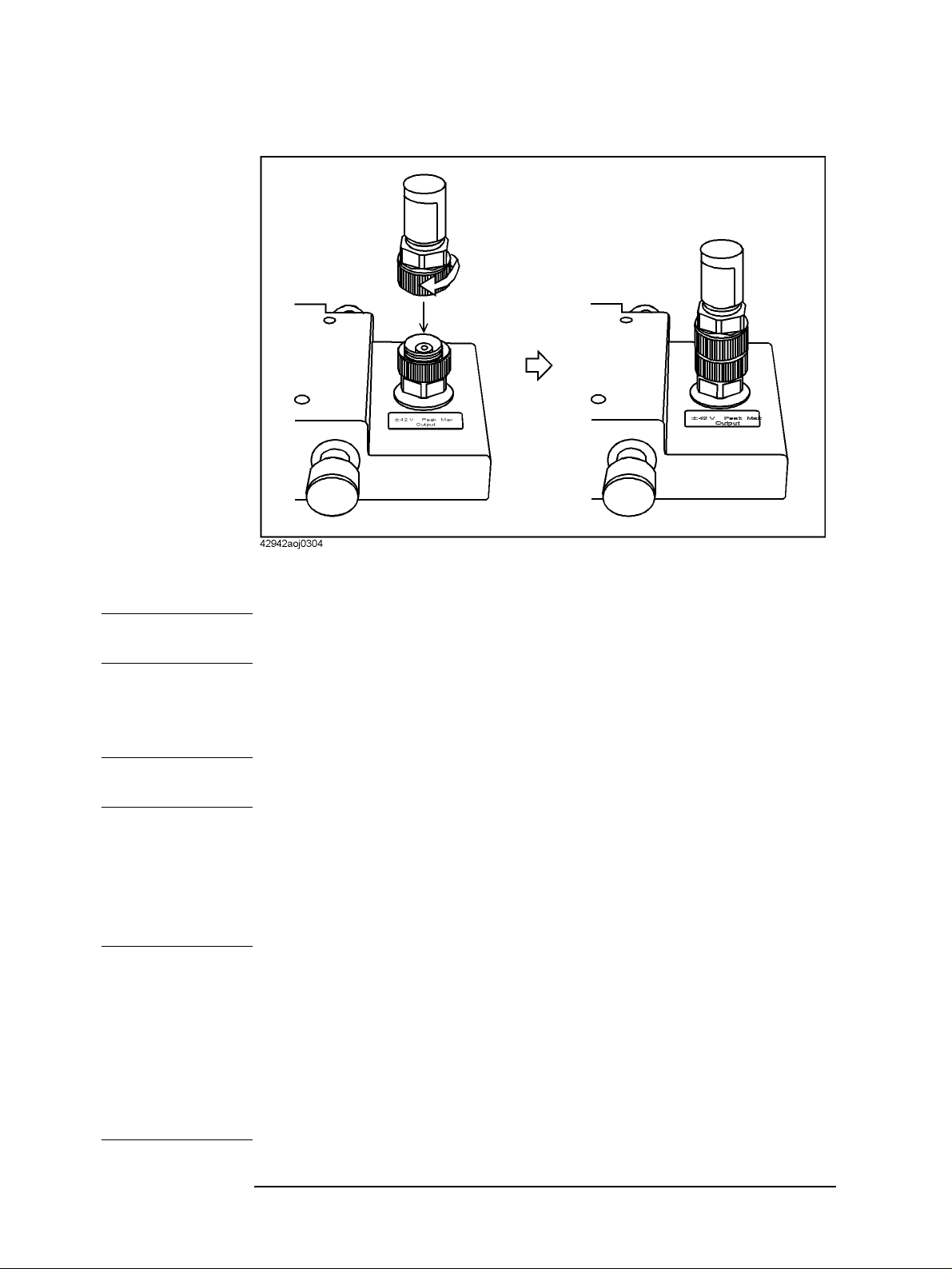
Preparation of Measurement Accessories
Adapter Setting
Figure 4-7 Connecting LOAD (50 Ω) to the 42942A
Step 11 . Press the
LOAD [-] key to start the load data measurement.
NOTE When the load data measurement is completed, the softkey label changes to
LOAD [DONE].
Step 12. Press the
done key to start calculating the adapter setup data from the measured OPEN,
SHORT, and LOAD data. The adapter setup data is automatically saved to the EEPROM
(nonvolatile memory) in the Agilent 4294A.
NOTE Press the cancel key to cancel the adapter setup process. If the adapter setup process is
canceled, the previously obtained data is saved as the available adapter setup data.
Adapter Setup Procedure for the 42941A
Perform the adapter setup for the 42941A Impedance Probe in accordance with the
following procedure (the o peration manual for the 4 2941A al so descri bes the adapter setu p
procedure).
NOTE Adapter setup should be performed at an ambient temperature as close as possible to the
temperature in which the device measurement will actually be made.
If the ambient temperature for your measurement is outside the range of ±5°C from the
adapter setup temperature, it is recommended that you perform adapter setup again at the
appropriate temperature.
It takes a few minutes to complete each setup data measurement.
During each data measurement, the message “WAIT--MEASURING ADJUSTMENT
KIT” is displayed in the instrument state area in the LCD's upper-left side.
78 Chapter 4
Page 79

Step 1. Make sure that the 42941A is correctly connected to the four-terminal pair port of the
Agilent 4294A.
Figure 4-8 Connecting the 42941A
Prepar ation of Measurement Accessories
Adapter Setting
NOTE The 42941A must be directly connected to the four-terminal pair port of the Agilent
4294A. If another accessory su ch as a cable or adapter is inserted between the 42941A and
the four-terminal pair port of the Agilent 4294A, the correct adapter setup data cannot be
obtained and correct device measurement cannot be performed after the adapter setup.
Step 2. More than 30 minutes warm-up time is required after turning on the Agilent 4294A.
Step 3. Make the correct adapter selection for the 42941A in accordance with the “Adapter
Selection” on page 68.
Step 4. After performing Step 4 of the “Adapter Selection” on page 68, press the
SETUP key to
display the Adapter Setup Menu.
Step 5. Leave the 3.5-mm port of the 42941A open (no connection). There is no OPEN standard
for the 42941A.
Step 6. Press the
PHASE COMP [-] key to start the phase compensation data measurement.
NOTE The traces on the LCD display do not change during the phase compensation data
measurement.
When the phase compensation data measurement is completed, the softkey label changes
to PHASE COMP [DONE].
Step 7. With nothing connected to the 3.5-mm port, press the
OPEN [-] key to start open data
measurement.
Chapter 4 79
Page 80

Preparation of Measurement Accessories
Adapter Setting
NOTE When the load data measurement is completed, the softkey label changes to
OPEN [DONE].
Step 8. Connect the SHOR T (0 Ω, HRM 504) to the 3.5-mm port (the SHORT is furnished with the
42941A Impedance Probe).
Step 9. Press the
SHORT [-] key to start the short data measurement.
NOTE When the short data measurement is completed, the softkey label changes to
SHORT [DONE].
Step 10. Remove the SHORT (0 Ω, HRM 504) from the 3.5-mm port of the 42941A. Then connect
the LOAD (50 Ω, HRM 601) to the 3.5-mm port (the LOAD is furnished with the 42941A
Impedance Probe).
Step 11 . Press the
LOAD [-] key to start the load data measurement.
NOTE When the load data measurement is completed, the softkey label changes to
LOAD [DONE].
Step 12. Press the
done key to start calculating the adapter setup data from the measured phase
compensation, OPEN, SHORT, and LOAD data. The adapter setup data is automatically
saved to the EEPROM (nonvolatile memory) in the Agilent 4294A.
NOTE Press the cancel key to cancel the adapter setup process. If the adapter setup process is
canceled, the previously obtained data is saved as the available adapter setup data.
80 Chapter 4
Page 81

5 Setting Measurement Conditions
This chapter explains how to set up the measurement conditions for the Agilent 4294A
Precision Impedance Analyzer, including the measurement signal and sweep.
NOTE Be sure to perform the “adapter setting” before starting your measurement. See “Adapter
Setting” on page 67 for how to perform the adapter setting.
81
Page 82

Setting Measurement Conditions
Putting the Agilent 4294A into the Preset State (Presetting)
Putting the Agilent 4294A into the Preset State (Presetting)
Step 1. Press the [Preset] key.
Executing presetting will put the Agilent 4294A into an initial state called the “preset state.”
When turning on the power to the Agilent 4294A, a power- on st ate file is loaded to rest ore
the setting stored in the file if it has been saved in the mass storage of the Agilent 4294A.
We recommend that you to perform presetting by pressing the
put the Agilent 4294A into a new setting, regardless of whether it is done immediately after
turning the power on.
[Preset] key each time you
Note that the adapter setting is not affected by initialization with the
set, it cannot be modified by pressing the [Preset] key.
[Preset] key; once it is
82 Chapter 5
Page 83

Setting Measurement Conditions
Selecting Trace (Active Trace)
Selecting Trace (Active Trace)
The Agilent 4294A can display the measurement results of one sweep measurement in two
traces (waveforms) on the screen. These traces are called trace A and trace B. Various
conditions or analyses can be applied to these traces independently, while others can be
applied to them in common, such as the sweep range.
Step 1. Press one of the following keys to select a trace for setting conditions or for analysis.
Active trace Key stroke
Trace A
Trace B [B]
[A]
The settings using the following keys (key operations) can be specified for trace A and
trace B independently. Before making settings with these keys (key operations), be sure to
check and select the active trace.
•[Format]
• [Display] - DEF TRACE [] (except for DATA → MEMORY)
• [Display] - OFFSET
• [Display] - more 1/2 - TITLE
• [Scale Ref]
• Keys in the MARKER block
The settings using keys other than those above can be commonly applied to trace A and
trace B. Therefore, you do not have to select the active trace or check its state before
making those settings. However, there are some exceptions. Refer to the operational
procedure of each function for details.
Chapter 5 83
Page 84

Setting Measurement Conditions
Selecting Sweep Parameter
Selecting Sweep Parameter
Step 1. Press the [Sweep] key.
Step 2. Press the PARAMETER [ ] key.
Step 3. Select the desired sweep parameter
Sweep parameter Key stroke
Frequency Oscillator level (voltage or current) OSC LEVEL dc bias DC BIAS
FREQ
NOTE When selecting the oscillator level as a sweep parameter, follow the steps shown in
“Selecting Unit for Oscillator Level (Voltage or Current)” on page 106 to select sweeping
by voltage or current level.
When selecting the dc bias as a sweep parameter, proceed to the setting shown in “Setting
and Applying dc Bias” on page 107.
The sweep parameter that is currently selected appears in the key label
PARAMETER [ ] key.
Softkey label Selecte d sweep parameter
PARAMETER [FREQ] Frequency PARAMETER [OLEV] Oscillator level (voltage or current) PARAMETER [DCB] dc bias
[ ] of the
NOTE See “Using Time as Sweep Parameter (Zero Span Sweep)” on page 94 for the
measurement with time as a sweep parameter (zero span measurement).
The sweep parameter can be set to trace A and trace B in common. It is not necessary to
select an active trace or to verify the current selection before setting the parameter.
84 Chapter 5
Page 85
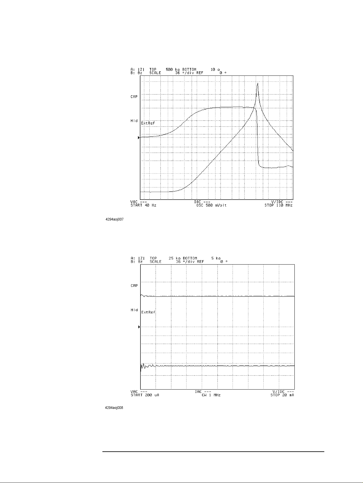
Figure 5-1 Sweep by Frequency
Setting Measurement Conditions
Selecting Sweep Par a met e r
Figure 5-2 Sweep by signal source current level
Chapter 5 85
Page 86

Setting Measurement Conditions
Selecting Sweep Parameter
Figure 5-3 Sweep by dc current bias (Constant dc bias current mode)
86 Chapter 5
Page 87

Selecting Linear, Log, or List Sweep
Selecting Linear, Log, or List Sweep
Step 1. Press the [Sweep] key to display the sweep menu.
Step 2. Press the TYPE [ ] key to display th e sweep type menu.
Step 3. Press one of the following keys to select the sweep type.
Sweep type Key stroke
Setting Measurement Conditions
Linear sweep Log (logarithm) sweep LOG List sweep LIST
LINEAR
NOTE If the oscillator level or the dc bias is selected as the sweep parameter, you cannot select the
log sweep. For how to select the sweep parameter, refer to Appendix , “Selecting Sweep
Parameter,” on page 84.
List sweep cannot be selected unless a list sweep table is prepared. Refer to “Sweeping
Multiple Sweep Ranges with Different Conditions in a Single Action (List Sweep)” on
page 116 to create the list sweep table.
The sweep type that is currently selected appears in the key label
Softkey label Selecte d sweep parameter
TYPE [FREQ] Linear sweep TYPE [LOG] Log sweep TYPE [LIST] List sweep
[ ] of the TYPE [ ] key.
NOTE The sweep type can be set to trace A and tr ace B in common. I t is n ot necessary to select an
active trace or to verify the current selection before setting the sweep type.
Chapter 5 87
Page 88

Setting Measurement Conditions
Selecting Linear, Log, or List Sweep
Figure 5-4 Linear sweep
Figure 5-5 Log (logarithm) sweep
88 Chapter 5
Page 89

Setting Measurement Conditions
Setting Sweep Range
Setting Sweep Range
Sweep range can be set by specifying either start and stop values or center and span values.
NOTE The measurement range can be set to trace A and trace B in common. It is not n ecessary to
select an active trace or to verify the current selection before setting the range.
Setting by start and stop values
Step 1. Press the [Start] key. This will display the current setting for sweep start value in the
parameter settings area located in the upper-left part of the screen.
Step 2. Use the keys or the rotary knob in the ENTRY block in one of the following ways to
specify a value for the sweep start.
• Enter the desired value with the numeric keys (
of the unit keys (
• Turn the rotary knob (❍
[G/n], [M/µ], [k/m], or [×1]).
❍) until the desired value is set.
❍❍
[0] to [9], [.], and [-]) and then press one
• Press the step keys ([↑][↓]) to set the desired value.
Step 3. Press the
[Stop] key. This will display the current setting for the sweep stop value in the
parameter settings area in the upper-left part of the screen.
Step 4. Use the keys or the rotary knob in the ENTRY block in one of the following ways to
specify a value for the sweep stop.
• Enter the desired value with the numeric keys (
of the unit keys (
• Turn the rotary knob (
[G/n], [M/µ], [k/m], or [×1]).
❍
❍) until the desired value is set.
❍❍
[0] to [9], [.], and [-]) and then press one
• Press the step keys ([↑][↓]) to set the desired value.
NOTE When the sweep parameter is set to frequency, the sweep start value cannot be greater than
the sweep stop value. Sweep with decreasing freq uency can b e po ssible by se tting a sw eep
range with increasing frequency and then specifying a downward sweep direction. Refer to
“Selecting Sweep Direction” on page 99 to specify the sweep direction.
Setting by center and span values
Step 1. Press the [Center] key. This will display the current setting for the sweep center value in
the parameter settings area located in the upper-left part of the screen.
Step 2. Use the keys or the rotary knob in the ENTRY block in one of the following ways to
specify a value for the sweep center.
• Enter the desired value with the numeric keys (
of the unit keys (
• Turn the rotary knob (❍
[G/n], [M/µ], [k/m], or [×1]).
❍) until the desired value is set.
❍❍
[0] to [9], [.], and [-]) and then press one
Chapter 5 89
Page 90

Setting Measurement Conditions
Setting Sweep Range
• Press the step keys ([↑][↓]) to set the desired value.
Step 3. Press the
[Stop] key. This will display the current setting for the sweep stop value in the
parameter settings area in the upper-left part of the screen.
Step 4. Use the keys or the rotary knob in the ENTRY block in one of the following ways to
specify a value for the sweep stop.
• Enter the desired value with the numeric keys (
of the unit keys (
• Turn the rotary knob (
[G/n], [M/µ], [k/m], or [×1]).
❍
❍) until the desired value is set.
❍❍
[0] to [9], [.], and [-]) and then press one
• Press the step keys ([↑][↓]) to set the desired value.
Setting sweep range with marker
The sweep start value, sweep stop value, and sweep center value are set to the value
indicated by the main marker on the trace. Also, the sweep span value can be set to the
delta value between the main marker and ∆ marker.
Step 1. Specify the active trace (the trace for setting) as the trace having the main marker that you
want to use for setting a sweep range.
Active trace Key stroke
Trace A
Trace B [B]
[A]
Step 2. Move the main marker to the point you want to use as a new sweep start value, sw eep stop
value, or sweep center value. The main marker can be moved in either of the following
ways.
•Press the
[Marker] key to display the current sweep parameter value showing the
current main maker’s position in the parameter settings area in the upper-left part of the
screen. Then, use the keys in the ENTRY block to move the main marker to the desired
location.
•Press the
MAX, MIN, TARGET, and PEAK keys to locate the main marker to the desired position.
Step 3. Press the
[Search] key to display the search menu. Then, use the search function with
[Marker →] key to di splay the marker Æ menu.
Step 4. Select one of the following methods to specify the sweep start value, sweep stop value, or
sweep center value as the location of the current main marker.
Setting sweep range Key stroke
Specify a new sweep start value as the current main marker location.
Specify a new sweep stop value as the current main marker location.
Specify a new sweep center value as the current main marker location.
MKR → START
MKR → STOP
MKR → CENTER
90 Chapter 5
Page 91

Setting Measurement Conditions
Setting sweep range Key stroke
Setting Sweep Range
Set the difference in the swee p parameter v alue
MKR ∆ → SPAN
between the current main marker positi on and
1
the delta marker position
as the new sweep
span value.
Search the trace for a peak2 and specify a new
more 1/2 - PEAK → CENTER
sweep center value as the location of the p eak
found.
The current main marker position is set as the
new sweep center value, and th e new sweep
more 1/2 - ZOOMING APERTURE to set the
zooming aperture, and then
MKR ZOOM
span value is set dependi ng on the specified
zooming aperture
3
. As a result, the trace will
be magnified (zoomed in) by focusing on the
main marker position.
1. For how to use the main marker and the delta marker, refer to Chapter 8 , “Analysis and
Processing of Result,” on page 211.
2. Refer to “Search the maximum/minimum peak” on page 228 and “Define the Peak” on
page 232 for information on the peak search f unction.
3. For the ratio of the new sweep span value to the current sweep span value (%), you can
set a value between 0.0 1% and 100% in steps of 0.0 1%. The power-on and preset settings are both 10%.
NOTE After you change the sweep range, the trace for the new sweep range will not be displayed
unless you perform a new sweep measurement.
Figure 5-6 Before
MKR → CENTER
Chapter 5 91
Page 92

Setting Measurement Conditions
Setting Sweep Range
Figure 5-7 After MKR → CENTER
Figure 5-8
92 Chapter 5
Page 93

Figure 5-9
Setting Measurement Conditions
Setting Sweep Range
Chapter 5 93
Page 94

Setting Measurement Conditions
Using Time as Sweep Parameter (Zero Span Sweep)
Using Time as Sweep Parameter (Zero Span Sweep)
Setting the sweep span to zero allows you to perform a measurement with time as a sweep
parameter. This kind of sweep is also called zero span sweep.
Step 1. Press the
[Sweep] key to display th e sweep menu.
Step 2. Press the PARAMETER [ ] key to display the sweep parameter menu.
Step 3. Press the
Step 4. Press the
FREQ key to select frequency as a sweep parameter.
[Span] key. This will display the current setting for sweep span value in the
parameter settings area in the upper-left part of the screen.
Step 5. Press
Step 6. Press the
[0] - [×1] to set the sweep span value to zero.
[Center] key. At this point, the value displayed in the parameter settings area in
the upper-left part of the screen shows that the signal source used has a fixed, not swept,
frequency.
Step 7. Use the keys or the rotary knob in the ENTRY block in one of the following ways to set the
fixed freq uency displayed on the s creen.
• Enter the desired value with the numeric keys (
of the unit keys (
• Turn the rotary knob (❍
[G/n], [M/µ], [k/m], or [×1]).
❍) until the desired value is set.
❍❍
[0] to [9], [.], and [-]) and then press one
• Press the step keys ([↑][↓]) to set the desired value.
Step 8. Press the
[Sweep] key to display the sweep menu.
Step 9. Press the TIME key to display the sweep time menu.
Step 10. Press the
SWEEP TIME key. This will display the current setting for sweep time in the
parameter settings area in the upper-left part of the screen. In other words, this shows the
current sweep span value in the time sweep.
Step 11 . Use the keys or the rotary knob in the ENTRY block in one of the following ways to
specify a value for the sweep time (sweep span).
• Enter the desired value with the numeric keys (
of the unit keys (
• Turn the rotary knob (
[G/n], [M/µ], [k/m], or [×1]).
❍
❍) until the desired value is set.
❍❍
[0] to [9], [.], and [-]) and then press one
• Press the step keys ([↑][↓]) to set the desired value.
NOTE Sweep time (sweep span value) can be set up to 10,000 seconds (approx. 2.8 hours).
When using a marker immediately after setting the zero span sweep from the preset state,
the sweep parameter value shown by the marker in the parameter settings area in the
upper-left part of the screen is indicated by a measurement point number (serial number s
from 1 to the number of points for all measurement points). At the same time, an identical
value entered with the
[Center] key for all measurement points is indicated in the marker
sweep parameter area in the upper-right p art of the screen . This sweep parameter v alue can
be converted into a time-based value for display by pressing the
94 Chapter 5
Page 95

Setting Measurement Conditions
Using Time as Sweep Parameter (Zero Span Sweep)
[Utility] - MKR X-AXIS [ ] - TIME keys.
Sweep parameters other than frequency can be selected in Step 3. In such a case, the fixed
value for the signal source is reflected in the selected parameter in Steps 5 and 6.
Settings for signal sources other than the fixed value in Steps 5 and 6 can be made in the
signal source menu, which can be accessed by pressing the
[Source] key.
The zero span sweep can also be achieved with the
sweep start value and sweep stop value as the same value.
Figure 5-10 Sweep span value = 20 kHz
[Start] and [Stop] keys to specify the
Chapter 5 95
Page 96

Setting Measurement Conditions
Using Time as Sweep Parameter (Zero Span Sweep)
Figure 5-11 Sweep span value = 0 Hz (zero span sweep)
96 Chapter 5
Page 97

Setting Measurement Conditions
Setting Number of Points (NOP)
Setting Number of Points (NOP)
Step 1. Press [Sweep] to display the sweep menu.
Step 2. Press the NUMBER OF POINTS key. This will display the current setting for number of
points in the parameter settings area in the upper-left part of the screen.
Step 3. Use keys or the rotary knob in the ENTRY block in one of the following ways to specify a
value for the number of points.
• Enter the desi red value with the numeric keys (
• Turn the rotary knob (
• Press the step keys ([↑][↓]) to set the desired value.
NOTE The number of sweep points can be set to any integer from 2 to 801.
When list is selected as a sweep type (list sweep), use a list sweep table to set the number
of points.
Setting the number of points is applied commonly to traces A and B.
Figure 5-12 Number of points: 51
❍
❍) until the desired value is set.
❍❍
[0] to [9]) and then press the [×1] key.
Chapter 5 97
Page 98

Setting Measurement Conditions
Setting Number of Points (NOP)
Figure 5-13 Number of points: 801
98 Chapter 5
Page 99

Setting Measurement Conditions
Selecting Sweep Direction
Selecting Sweep Direction
DUT can be measured in the desired sweep direction when its characteristics has hysteresis
with the sweep parameter.
Step 1. Press the
[Sweep] key to display th e sweep menu.
Step 2. Press the DIRECTION [ ] key to select the desired sweep direction (pr essing the key toggles
the direction).
Softkey label Selected sweep direction
DIRECTION [UP] Upward (from sweep start value to sweep stop
value)
DIRECTION [DOWN] Downward (from sweep stop value to sweep
start value)
NOTE Setting the sweep direction is applied commonly to traces A and B.
Chapter 5 99
Page 100

Setting Measurement Conditions
Manual Sweep (Measurement at a Specified Point)
Manual Sweep (Measurement at a Specified Point)
In the normal sweep mode, the Agilent 4294A performs measurement by automatically
changing the measurement point in response to triggering. When the set of measurements
performed is as many as the number of points, this is regarded as one sweep. On the other
hand, in the manual sweep mode the Agilent 4294A does not automatically change
measurement points (sweep), and the meas urement at a single point s pecified by the user is
regarded as one sweep. Since the measurement point can be arbitrarily specified by the
user, this function can be called a user-defined manual sweep. The Agilent 4294A will
continue measurement (sweep) at the same point unless it is changed by the user. Follow
the steps below to execute the manual sweep.
Step 1. Press the
Step 2. Press the
the softkey label to
[Sweep] key to display th e sweep menu.
MANUAL SWP on OFF key to turn the manual sweep function ON. Th is changes
MANUAL SWP ON off. At the same time, the current measurement
point “1” for manual sweep and sweep parameter value for the point are displayed in the
parameter settings area located in the upper left of the screen.
Step 3. Use the keys or the rotary knob in the ENTRY block in one of the following ways to
specify the measurement point (any integer value from 1 to the number of points).
• Enter the desired value with the numeric keys (
[×1] key.
❍
• Turn the rotary knob (
❍) until the desired value is set.
❍❍
[0] to [9], [.], and [-]) and then press the
• Press the step keys ([↑][↓]) to set the desired value.
NOTE Instead of directly setting the measurement point by using the keys or the rotary knob in the
ENTRY block, it can be set by moving the main marker to your desired point for the
manual sweep and pressing the
[Marker →] - MKR → MANUAL SWP keys. This operation
can assign the manual sweep point to the location of the main marker and is effective
before activating the manual sweep.
When you turn the sweep function ON and specify a measurement point, no measurement
is performed at the point as long as the sweep mode is disabled or the trigger is not
generated.
The number of points can be commonly set to traces A and B.
100 Chapter 5
 Loading...