

Page 1

HP 4291B RF Impedance/Material Analyzer
Programming Manual
SERIAL NUMBERS
This manual applies directly to instruments with serial number
prex \JP1KE" and above, or whose rmware is version 1.0.
For additional important information about serial numbers,
read \Serial Number" in Appendix A of this Manual.
HP Part No. 04291-90037
Printed in JAPAN March 1998
Second Edition
Page 2

Notice
The information contained in this document is subject to change without notice.
This document contains proprietary information that is protected by copyright. All rights are
reserved. No part of this document may be photocopied, reproduced, or translated to another
language without the prior written consent of the Hewlett-Packard Company.
Hewlett-Packard Japan, LTD.
Kobe Instrument Division
1-3-2, Murotani, Nishi-ku, Kobe-shi,
Hyogo, 651-2241 Japan
The customer shall have the personal, non-transferable rights to use
PROGRAMS in this manual for the Customer's internal operations
, copy, or modify SAMPLE
. The customer shall use the
SAMPLE PROGRAMS solely and exclusively for their own purpose and shall not license, lease,
market, or distribute the SAMPLE PROGRAMS or modication of any part thereof.
HP shall not be liable for the quality, performance, or behavior of the SAMPLE PROGRAMS. HP
especially disclaims that the operation of the SAMPLE PROGRAMS shall be uninterrupted or
error free. The SAMPLE PROGRAMS are provided AS IS.
HP DISCLAIMS THE IMPLIED WARRANTIES OF MERCHANTABILITY AND FITNESS FOR A
PARTICULAR PURPOSE.
HP shall not be liable for any infringement of any patent, trademark, copyright, or other
proprietary rights by the SAMPLE PROGRAMS or their use. HP does not warrant that the
SAMPLE PROGRAMS are free from infringements of such rights of third parties. However,HP
will not knowingly infringe or deliver software that infringes the patent, trademark, copyright,
or other proprietary right of a third party.
R
MS-DOS
c
is a U.S. registered trademark of Microsoft Corporation.
Copyright 1997,1998 Hewlett-Packard Japan, LTD.
Page 3

Manual Printing History
The manual printing date and part number indicate its current edition. The printing date
changes when a new edition is printed. (Minor corrections and updates that are incorporated
at reprint do not cause the date to change.) The manual part number changes when extensive
technical changes are incorporated.
December 1997
March 1998
::::::: ::::::: :::::: ::::::: ::::::: :::::: ::::::: ::::::: :::::: ::::::: ::::
::::: ::::::: ::::::: :::::: ::::::: ::::::: :::::: ::::::: ::::::: :::::: ::::
Second Edition
First Edition
iii
Page 4

Typeface Conventions
Bold
Boldface type is used when a term is dened. For example:
icons
symbols.
Italics
Italic type is used for emphasis and for titles of manuals and other
publications.
Italic type is also used for keyboard entries when a name or a variable
Computer
4
HARDKEYS
NNNNNNNNNNNNNNNNNNNNNNNNNN
SOFTKEYS
must be typed in place of the words in italics.For example:
lename
type the name of a le such as
means to type the word
file1
copy
, to type a space, and then to
.
Computer font is used for on-screen prompts and messages.
5
Labeled keys on the instrument front panel are enclosed in45.
Softkeys located to the right of the LCD are enclosed in
copy
NNNNN
.
Related Documentation Information
You can obtain more detailed information than provided by this manual by referring to the
following documents.
The following manuals are provided with the HP 4291B :
HP 4291B HP-IB Command Reference
for the complete HP-IB command list of the analyzer
are
.
HP 4291B Quick Start Guide
for learning about the analyzer itself and its front panel key
operation.
HP Instrument BASIC User's Handbook & its supplement for the HP 4291B
BASIC information.
The following documents also provide related information:
HP BASIC Programming Guide
for learning HP BASIC programming. (Furnished with the HP
BASIC system.)
Tutorial Description of the Hewlett-Packard Interface Bus
for an overview of the HP-IB and
IEEE 488 standard (HP literature no. 5952-0156).
Beginner's Guide to SCPI
for learning about a generic SCPI standard command set and its use
(HP part no. H2325-90001).
for Instrument
iv
Page 5

Contents
1. Introduction
How to Use This Manual . . . . . . . . . . . . . . . . . . . . . . . . . . . 1-1
Target Reader .... ...... ...... ...... ..... .... 1-1
What's in This Manual? ........................... 1-1
How to Use the Program Modules . . . . . . . . . . . . . . . . . . . . . . . 1-3
Building a Working Program Using Program Modules . . . . . . . . . . . . . 1-3
Initializing Module . . . . . . . . . . . . . . . . . . . . . . . . . . . . 1-3
Example ................................ 1-4
HP-IB Overview . . . . . . . . . . . . . . . . . . . . . . . . . . . . . . . 1-5
Controller . . . . . . . . . . . . . . . . . . . . . . . . . . . . . . . . . 1-5
Device Selector ...... ...... ...... ...... ......
HP-IB Commands ..............................
Common Commands . . . . . . . . . . . . . . . . . . . . . . . . . . . .
Instrument Control Commands .......................
Simple Commands . . . . . . . . . . . . . . . . . . . . . . . . . . . . .
Program Message Syntax . . . . . . . . . . . . . . . . . . . . . . . . . . .
Command Abbreviations . . . . . . . . . . . . . . . . . . . . . . . . . .
Upper and Lower Cases ..........................
Program Message Terminator . . . . . . . . . . . . . . . . . . . . . . . .
Multiple Messages .............................
Query and Response Message Syntax .. ...... ...... ......
Parameters ...... ...... ...... ...... ..... ...
Variable Types . . . . . . . . . . . . . . . . . . . . . . . . . . . . . .
Command Tree and Compound Header Usage .................
Preparation for Operation ..........................
Using Instrument BASIC for Controller ........ ...... .....
1. Connecting the HP-IB Cables ..................... 1-13
2. Setting the HP-IB Address . . . . . . . . . . . . . . . . . . . . . . . 1-13
3. Preparing Instrument BASIC . . . . . . . . . . . . . . . . . . . . . . 1-13
Using an External Controller . . . . . . . . . . . . . . . . . . . . . . . . 1-14
1. Connecting the HP-IB Cables ..................... 1-14
2. Setting the HP-IB Address . . . . . . . . . . . . . . . . . . . . . . .
3. Preparing HP BASIC ...... ...... ...... ..... ..
Sample Program Disk ............................
Loading a Program from Disk . . . . . . . . . . . . . . . . . . . . . . . .
1-6
1-7
1-7
1-7
1-7
1-8
1-8
1-8
1-8
1-9
1-9
1-9
1-9
1-11
1-13
1-13
1-14
1-14
1-15
1-15
Contents-1
Page 6

2. Setup and Measurement Program
Overview of HP-IB Control . . . . . . . . . . . . . . . . . . . . . . . . . . 2-1
Sending HP-IB Commands ......................... 2-1
Reducing Keystrokes by Eliminating Node Repetition ........... 2-2
Sending a Query and Reading the Response ................. 2-2
Automating the Impedance Measurement Procedure . . . . . . . . . . . . . . 2-3
1. Setting the Active Channel ........ ...... ...... ... 2-3
2. Setting Stimulus ............................ 2-4
Setting Frequency Sweep Range and Level .. ...... ..... ... 2-4
Setting OSC Level Sweep . . . . . . . . . . . . . . . . . . . . . . . . . 2-4
Setting dc Voltage Sweep (Option 001 Only) . . . . . . . . . . . . . . . . 2-5
Setting dc Current Sweep (Option 001 Only) . . . . . . . . . . . . . . . . 2-5
3. Performing Calibration ......................... 2-6
Checking Calibration State . . . . . . . . . . . . . . . . . . . . . . . . 2-6
4. Setting Port Extension and Electrical Length .. ...... ...... . 2-7
5. Performing Fixture Compensation .................... 2-7
6. Setting Measurement Parameter ..................... 2-9
7. Setting Display Format ......................... 2-10
8. Setting dc Bias (Option 001 Only) .. ...... ...... ...... 2-11
9. Triggering a Measurement . . . . . . . . . . . . . . . . . . . . . . . . 2-12
10. Setting Scale and Reference ......................
11. Getting Measured Data to the Controller ...... ...... ....
Sample Program: Basic Impedance Measurement Program ...........
Automating the Permittivity Measurement (Option 002 Only) . . . . . . . . . .
4. Selecting Fixture ............ ...... ..... .....
5. Performing Fixture Compensation ....................
6. Setting MUT Thickness .........................
7. Setting Measurement Parameter .....................
Cole-Cole Plot . . . . . . . . . . . . . . . . . . . . . . . . . . . . . .
Automating the Permeability Measurement (Option 002 Only) . . . . . . . . . .
4. Selecting Fixture ............ ...... ..... .....
5. Performing Fixture Compensation ....................
6. Setting MUT Size .. ...... ...... ..... ...... ...
7. Setting Measurement Parameter .....................
2-13
2-13
2-14
2-16
2-16
2-16
2-17
2-18
2-18
2-19
2-19
2-19
2-20
2-20
3. Data Processing and Transfer
Data Arrays . . . . . . . . . . . . . . . . . . . . . . . . . . . . . . . . . 3-1
Raw Data Array . . . . . . . . . . . . . . . . . . . . . . . . . . . . . . 3-2
Data Array ................................ 3-2
Data Trace Array ...... ...... ...... ...... ..... 3-2
Calibration Coecient Array . . . . . . . . . . . . . . . . . . . . . . . .
Accessing Arrays ............................
Compensation Coecient Array ...... ...... ...... ....
Accessing Arrays ............................
Monitor Array . . . . . . . . . . . . . . . . . . . . . . . . . . . . . . .
Stimulus Array ..............................
Arrays for Memory Trace . . . . . . . . . . . . . . . . . . . . . . . . . .
Accessing Memory Array . . . . . . . . . . . . . . . . . . . . . . . . .
Accessing Memory Trace Array . . . . . . . . . . . . . . . . . . . . . . 3-6
Data Transfer Methods . . . . . . . . . . . . . . . . . . . . . . . . . . . . 3-7
ASCII Transfer ..............................
Binary Transfer ..............................
Data Header . . . . . . . . . . . . . . . . . . . . . . . . . . . . . . .
Getting Data from Analyzer .. ...... ...... ..... ....
Sample Programs: Compensation Data Transfer ................
Contents-2
3-3
3-4
3-4
3-4
3-5
3-5
3-6
3-6
3-7
3-8
3-9
3-10
3-11
Page 7

Storing Compensation Data to Disk (CMP STOR) . . . . . . . . . . . . . . . 3-11
Loading Compensation Data from Disk (CMP LOAD).... ...... ... 3-13
4. Using Status Reporting System
General Status Register Model ........................ 4-1
Event Register . . . . . . . . . . . . . . . . . . . . . . . . . . . . . . . 4-2
Enable Register .............................. 4-2
Status Byte Register . . . . . . . . . . . . . . . . . . . . . . . . . . . . 4-2
Transition Filter and Condition Register . . . . . . . . . . . . . . . . . . . 4-3
Status Register Structure . . . . . . . . . . . . . . . . . . . . . . . . . . . 4-4
How to Use the Status Registers in a Program . . . . . . . . . . . . . . . . . 4-8
Reading an Event Register Directly . . . . . . . . . . . . . . . . . . . . . 4-8
SRQ and Interrupt . . . . . . . . . . . . . . . . . . . . . . . . . . . . . 4-9
Sample Program: Performing Calibration ................... 4-11
5. Using the Trigger System
Trigger System ............................... 5-2
Idle State ...... ...... ...... ..... ...... .... 5-2
Wait for Trigger State ........................... 5-2
Measurement State ............................ 5-3
Sweeping Once Using the HP-IB Trigger . . . . . . . . . . . . . . . . . . .
Sweeping a Specied Number of Times ...................
Triggering on Each Point Using the Manual Trigger . . . . . . . . . . . . . .
6. Using the I/O Port
I/O Port Pin Assignment ...........................
Accessing I/O Port ..............................
Access I/O Port from the External Controller .... ...... ......
Sample Program: BIN Sorting Using the I/O Port...... ...... ....
5-4
5-4
5-5
6-1
6-2
6-2
6-3
7. Using the User Traces
What's the User Trace? ...........................
Using a User Trace . . . . . . . . . . . . . . . . . . . . . . . . . . . . . .
Setting A Grid . . . . . . . . . . . . . . . . . . . . . . . . . . . . . . .
Setting Data Train for The Trace .. ...... ...... ...... ..
Turning ON the User Trace . . . . . . . . . . . . . . . . . . . . . . . . . 7-4
Using the Marker on a User Trace . . . . . . . . . . . . . . . . . . . . . . 7-4
Clearing a User Trace .... ...... ...... ...... ..... 7-4
Sample Program: Time Characteristic Measurement .............. 7-5
8. Programming Miscellaneous
Using Disks .................................
Saving the Analyzer Status . . . . . . . . . . . . . . . . . . . . . . . . .
Entering Trace Data From the Disk into a Program Variable ......... 8-2
Sample Program: Making HP CITIle .....................
Printing . . . . . . . . . . . . . . . . . . . . . . . . . . . . . . . . . . .
To Print Analyzer Display .........................
Printer Preparation .... ...... ...... ..... ......
Execute Print ........ ...... ..... ...... ..... 8-5
To Observe Printing ............................ 8-5
Controlling Instrument BASIC from an External Controller . . . . . . . . . . .
Reading or Putting the Variable Data .......... ...... ....
Reading Numeric Variable ........................
Putting Numeric Variable . . . . . . . . . . . . . . . . . . . . . . . . .
Reading String Variable .... ...... ...... ...... ...
7-1
7-2
7-3
7-3
8-1
8-1
8-3
8-5
8-5
8-5
8-6
8-6
8-6
8-6
8-7
Contents-3
Page 8

Putting String Variable . . . . . . . . . . . . . . . . . . . . . . . . . . 8-7
Simultaneously Running Instrument BASIC and External Controller Programs . 8-8
Controlling Instrument BASIC Execution Status .............. 8-8
Determining Instrument BASIC Execution State ...... ...... .. 8-8
Transferring Program Source . . . . . . . . . . . . . . . . . . . . . . . . 8-10
Uploading a Program from Controller to Instrument BASIC . . . . . . . . . 8-10
Downloading a program from Instrument BASIC to the Controller . . . . . . 8-10
Debugging Program ............................. 8-11
Processing Time Measurement .... ...... ...... ...... .. 8-12
Key Sequence Logging . . . . . . . . . . . . . . . . . . . . . . . . . . . . 8-13
Generating Equivalent Program For Empty Editor . . . . . . . . . . . . . . 8-13
Inserting Equivalent Codes into Your Program . . . . . . . . . . . . . . . . 8-13
Limitations ................................ 8-14
File Transfer Function . . . . . . . . . . . . . . . . . . . . . . . . . . . . 8-15
File Transfer from HP 4291B to External Controller .......... ... 8-16
File Transfer from External Controller to HP 4291B .......... ... 8-18
Displaying List of Files in Current Directory . . . . . . . . . . . . . . . . . 8-20
9. Facilitating Program Execution and Utilizing Storage Devices
How to Save Programs of Instrument BASIC . . . . . . . . . . . . . . . . . . 9-1
The Procedure to Save Programs ......................
Running a Program through the Softkey Interface . . . . . . . . . . . . . . .
Automatically Starting a Program at Power-ON (AUTOST) ...........
About
AUTOREC
...... ...... ...... ...... ......
Using Storage Devices ............................
BASIC Commands for Setting up the Storage Devices . . . . . . . . . . . . .
Floppy Disk Drive . . . . . . . . . . . . . . . . . . . . . . . . . . . . .
Memory Disk ...............................
Transfering Data between Floppy Disk and Memory Disk . . . . . . . . . . .
9-1
9-2
9-3
9-3
9-4
9-4
9-4
9-4
9-4
10. Introducing HP Instrument BASIC System
Overview of HP Instrument BASIC ......................
Controlling the Analyzer . . . . . . . . . . . . . . . . . . . . . . . . . . .
Using HP Instrument BASIC for the First Time . . . . . . . . . . . . . . . . .
Allocating Screen Area for HP Instrument BASIC .... ...... ....
Entering BASIC Statements from the Front Panel Keys . . . . . . . . . . . . . 10-3
Getting into/out of the EDIT Mode ...................... 10-3
Getting into the EDIT Mode ........................ 10-3
Entering the EDIT Mode from the Keyboard . . . . . . . . . . . . . . . . . 10-3
Getting Out of the EDIT Mode ...... ...... ..... ...... 10-3
Editing Programs in the EDIT Mode . . . . . . . . . . . . . . . . . . . . . .
Deleting Characters .... ...... ...... ...... ......
Back Space .......... ...... ...... ..... ....
Deleting Characters ...........................
Inserting Characters ........ ...... ...... ...... ..
Moving the Cursor . . . . . . . . . . . . . . . . . . . . . . . . . . . . .
Scrolling Lines and Pages . . . . . . . . . . . . . . . . . . . . . . . . . .
Scrolling Lines . . . . . . . . . . . . . . . . . . . . . . . . . . . . . .
Scrolling Pages . . . . . . . . . . . . . . . . . . . . . . . . . . . . . . 10-4
Jumping from the Current Line . . . . . . . . . . . . . . . . . . . . . . . 10-5
Jumping to a Specied Line .......................
Jumping to the Top/Bottom of a Program .................
Inserting/Deleting/Recalling Lines . . . . . . . . . . . . . . . . . . . . . .
Clearing Line ...............................
Renumbering Program Line Numbers ...... ...... ...... ...
10-1
10-2
10-2
10-2
10-4
10-4
10-4
10-4
10-4
10-4
10-4
10-4
10-5
10-5
10-5
10-5
10-5
Contents-4
Page 9

Listing Programs . . . . . . . . . . . . . . . . . . . . . . . . . . . . . . . 10-6
Listing on the Screen .... ...... ...... ...... ..... 10-6
Listing to the Printer . . . . . . . . . . . . . . . . . . . . . . . . . . . . 10-6
Saving Programs (SAVE) .... ...... ...... ...... ..... 10-6
Listing File Names (CAT).... ...... ...... ...... ..... 10-7
Listing to Screen . . . . . . . . . . . . . . . . . . . . . . . . . . . . . . 10-7
Listing to Printer .... ...... ...... ...... ...... . 10-8
Getting Programs (GET) ........................... 10-8
On Key Label Function . . . . . . . . . . . . . . . . . . . . . . . . . . . . 10-8
Pass Control Between the External Controller . . . . . . . . . . . . . . . . . 10-9
Pass Control . . . . . . . . . . . . . . . . . . . . . . . . . . . . . . . . 10-9
To Execute an HP Instrument BASIC Command from the External Controller . 10-10
To Load an Array in an HP Instrument BASIC Program to the External Controller 10-11
Available I/O Interfaces and Select Codes .......... ...... ... 10-11
External RUN/CONTinue Connector . . . . . . . . . . . . . . . . . . . . . . 10-11
Graphics .................................. 10-12
HP Instrument BASIC Graphics Commands ................. 10-12
Hard Copies . . . . . . . . . . . . . . . . . . . . . . . . . . . . . . . . 10-13
Initial settings . . . . . . . . . . . . . . . . . . . . . . . . . . . . . . . 10-13
Example of Graphics Programming ..................... 10-13
Drawing a Straight Line .... ...... ...... ...... ...
Drawing a Circle . . . . . . . . . . . . . . . . . . . . . . . . . . . . .
The Keyboard . . . . . . . . . . . . . . . . . . . . . . . . . . . . . . . .
Character Entry Keys .. ...... ...... ..... ...... ..
Cursor-Control and Display-Control Keys ........ ...... ....
Numeric Keypad . . . . . . . . . . . . . . . . . . . . . . . . . . . . . .
Editing Keys .. ...... ...... ...... ...... .....
Program Control Keys .... ...... ...... ...... .....
System Control Keys . . . . . . . . . . . . . . . . . . . . . . . . . . . .
Softkeys and Softkey Control . . . . . . . . . . . . . . . . . . . . . . . .
Softkey Control Keys ...........................
Softkeys .................................
Softkeys Accessed form
Using
4
5
Key in Edit Mode ........ ...... ..... .....
CTRL
4
5
Key........ ...... ..... ...
F10
Run Light Indications ...........................
10-13
10-13
10-14
10-14
10-14
10-14
10-15
10-15
10-15
10-16
10-16
10-16
10-16
10-17
10-17
BASIC Commands Specic to HP 4291B . . . . . . . . . . . . . . . . . . . . 10-18
DATE................................... 10-18
DATE$ .... ...... ...... ...... ...... ...... 10-18
READIO . . . . . . . . . . . . . . . . . . . . . . . . . . . . . . . . . . 10-18
SET TIME . . . . . . . . . . . . . . . . . . . . . . . . . . . . . . . . . 10-19
SET TIMEDATE ..............................
TIME ...................................
TIME$ .. ...... ...... ...... ...... ...... ..
WRITEIO .................................
10-19
10-19
10-19
10-20
11. Command Reference
Conventions and Denitions .........................
ABORt .... ...... ...... ...... ..... ...... ..
BLIGHTfOFFjONj0j1g............................ 11-3
CALCulate Subsystem ............................ 11-4
CALCulate:EVALuate Subsystem .. ...... ...... ..... ...
:BAND:FULL[:STATe]fOFFjONj0j1g...... ...... ...... .
:BAND:SPAN DMARker . . . . . . . . . . . . . . . . . . . . . . . . .
:BAND:STARt MARKer .. ...... ...... ..... ......
:BAND:STOP MARKer .... ...... ...... ..... ....
11-1
11-2
11-4
11-4
11-4
11-4
11-5
Contents-5
Page 10

:COUPlefOFFjONj0j1g......................... 11-5
:EFFect:ONf1j2g............................ 11-5
:EPARameters ............................. 11-6
:EPARameters:CIRCuitfAjBjCjDjEg................... 11-6
:EPARameters:SIMulation .. ...... ...... ...... .... 11-6
:INTerpolatefOFFjONj0j1g....................... 11-6
:MSTatisticsfOFFjONj0j1g...... ...... ...... ...... 11-6
:MSTatistics:DATA? ........................... 11-7
:MSTatistics[:STATe]fOFFjONj0j1g.................... 11-7
:ON[1] \TRf1-21g" .. ...... ...... ...... ..... .. 11-7
:ON2f\OFF"j\ACV"j\ACC"j\DCV"j\DCC"g................ 11-8
:PEAK:EXCursionf<
:PEAK:EXCursion:Xf<
:PEAK:EXCursion[:Y]f<
numeric>j
numeric>j
numeric>j
DMARkerg................ 11-8
DMARkerg...... ..... .... 11-8
DMARkerg.............. 11-9
:PEAK:POLarityfPOSitivejNEGativeg.................. 11-9
:PEAK:THResholdf<
numeric>j
MARKerg................. 11-9
:PEAK:THReshold:STATefOFFjONj0j1g.................. 11-10
:R:FORMatfRIMaginaryjMLIPhasejMLOPhasejRXjGBjSWRPhaseg..... 11-10
:REFerence:DATA? ........................... 11-10
:REFerence:X<numeric>........................ 11-11
:REFerence:Y[1]<numeric
>
......................
:REFerence:Y2<numeric>.......................
:WIDTh:DATA? .............................
:WIDTh:STATefOFFjONj0j1g...... ...... ..... .....
:WIDTh:XPOSition:IN ...... ...... ...... ...... ..
:WIDTh:XPOSition:OUT .... ...... ...... ...... ...
:WIDTh:YfDIVS2jMULS2jDIV2jFIXed[,<numeric>]g...... .....
:Yf1-8g:DATA? [CH1jCH2] . . . . . . . . . . . . . . . . . . . . . . . .
:Yf1-8g:VALuef1j2g? [CH1jCH2] . . . . . . . . . . . . . . . . . . . . .
:Yf1-8g:XPOSition<numeric>......................
:Y[1]:XPOSition:LPEak .........................
:Y[1]:XPOSition:LTARget . . . . . . . . . . . . . . . . . . . . . . . . .
:Y[1]:XPOSition:MAXimum .. ...... ...... ...... ...
:Y[1]:XPOSition:MINimum . . . . . . . . . . . . . . . . . . . . . . . .
:Y[1]:XPOSition:NPEak ........ ...... ...... .....
11-11
11-11
11-12
11-12
11-12
11-12
11-13
11-13
11-14
11-14
11-14
11-15
11-15
11-15
11-15
:Y[1]:XPOSition:PEAK . . . . . . . . . . . . . . . . . . . . . . . . . . 11-15
:Yf1-8g:XPOSition:POINt<numeric>.................. 11-15
:Y[1]:XPOSition:RPEak ......................... 11-16
:Y[1]:XPOSition:RTARget ........................ 11-16
:Y[1]:XPOSition:TARGet<numeric>...... ...... ..... .. 11-16
:Y[1]:XPOSition:TRACkfMAXimumjMINimumjTARGetjPEAKjOFFg.... 11-16
CALCulate:FORMatfMLINearjPHASejUPHasejREALjIMAGinaryjLFACtor
j
LTANgentjCPjCSjLPjLSjDjQjRPjRSjCOMPlexg...... ...... ...
11-17
CALCulate:FORMat:UNIT:ANGLefDEGjRADg............... 11-18
CALCulate:LIMit Subsystem ........................
:BEEPerfOFFjONj0j1g.........................
:BEEPer:CONDitionfPASSjFAILg...... ...... ...... ..
:BEEPer[:STATe]fOFFjONj0j1g......................
11-18
11-18
11-18
11-18
:CLEar . . . . . . . . . . . . . . . . . . . . . . . . . . . . . . . . . 11-19
:CONTrol:OFFSet<numeric>...... ...... ...... .... 11-19
:LINEfOFFjONj0j1g...... ...... ...... ..... ...
:OFFSetf<
numeric>j
MARKerg.....................
:SAVE .................................
:SEGMent<numeric
>
...... ...... ..... ...... ..
:SEGMent:ADD . . . . . . . . . . . . . . . . . . . . . . . . . . . . .
11-19
11-20
11-20
11-20
11-21
Contents-6
Page 11

:SEGMent:CONTrol[:DATA]<numeric>...... ...... ..... 11-21
:SEGMent:DELete . . . . . . . . . . . . . . . . . . . . . . . . . . . . 11-21
:SEGMent:DELTa<numeric>...................... 11-21
:SEGMent:EDIT . . . . . . . . . . . . . . . . . . . . . . . . . . . . . 11-22
:SEGMent:LOWer<numeric>...................... 11-22
:SEGMent:MIDDlef<
numeric>j
MARKerg...... ...... .... 11-22
:SEGMent:SAVE............................. 11-22
:SEGMent:UPPer<numeric
>
...................... 11-23
:STATefOFFjONj0j1g.......................... 11-23
CALCulate:MATH1 Subsystem ...... ...... ...... ..... 11-23
:CATalog? . . . . . . . . . . . . . . . . . . . . . . . . . . . . . . . . 11-23
:DIMension1<numeric>...... ...... ...... ...... 11-24
:DIMension2<numeric(in)>,<numeric(out)>,<numeric(hei)>....... 11-24
[:EXPRession]:CATalog? ......................... 11-24
[:EXPRession]:NAMEfADMjDCOjPERjRCOg............... 11-24
:STATefOFFjONj0j1g.......................... 11-25
CALCulate:MATH2 Subsystem ...... ...... ...... ..... 11-25
[:EXPRession]:CATalog? ......................... 11-25
[:EXPRession]:NAMEfSUBjADDjDIVjMULg...... ...... .... 11-26
:STATefOFFjONj0j1g.......................... 11-26
CENT<numeric>, CHANf1j2g, CLEM, CONT . . . . . . . . . . . . . . . .
DATA Subsystem . . . . . . . . . . . . . . . . . . . . . . . . . . . . . . .
DATA[:DATA]fAOFFjGAINjMZAPg,<numeric>...............
DATA[:DATA] OFFS,f<
DATA[:DATA]<array>,f<
n2>g
.................................
numeric>j
MARKerg.................
block>j<numeric11>,<numeric12>, ... ,<numeric
DATA[:DATA]fEQC0jEQC1jEQL1jEQR1g,<numeric>.............
DATA[:DATA]? LFA ............................
DATA[:DATA]? LLIS . . . . . . . . . . . . . . . . . . . . . . . . . . . .
DATA[:DATA]? LMAR ...........................
DATA[:DATA]?MEM............................
DATA[:DATA]? SPAR............................
DATA[:DATA]:VALue?fSPARjDATAjMEMjMONg,<numeric>.........
DATA:DEFinefOADMjSIMPjLIMPg,f<
numeric>j
DATAjDTRjTR1g....... 11-31
DATA:DELetefOADMjSIMPjLIMPg.....................
11-27
11-27
11-27
11-28
11-28
11-29
11-29
11-29
11-30
11-30
11-30
11-30
11-31
DATA:POINt? LFA............................. 11-31
DATMEM .................................. 11-32
DIAGnostic Subsystem . . . . . . . . . . . . . . . . . . . . . . . . . . . . 11-32
DIAGnostic:EREFerence:STATe?............ ...... ..... 11-32
DIAGnostic:FREVision? .......................... 11-32
DIAGnostic:INIT:RESult? . . . . . . . . . . . . . . . . . . . . . . . . . .
DIAGnostic:SERVice Subsystem . . . . . . . . . . . . . . . . . . . . . . .
DIAGnostic:TEST Subsystem ........................
DFLT, DISPfDATAjMEMOjDATMg......................
11-32
11-33
11-33
11-34
DISPlay Subsystem . . . . . . . . . . . . . . . . . . . . . . . . . ..... 11-34
DISPlay:ANNotation:FREQuencyfOFFjONj0j1g............... 11-34
DISPlay:BACKlightfOFFjONj0j1g...... ...... ...... ....
DISPlay:BRIGhtness<numeric>...... ...... ...... ....
11-34
11-35
DISPlay:CMAP Subsystem ......................... 11-36
:COLorf1-14g:DEFault . . . . . . . . . . . . . . . . . . . . . . . . . . 11-36
:COLorf1-14g:HSL<numeric(Hue)>,<numeric(Sat)>,<numeric(Lum)>... 11-36
:DEFault ................................
:LOAD .................................
:STORe . . . . . . . . . . . . . . . . . . . . . . . . . . . . . . . . .
DISPlay:CONTrast<numeric>.......................
11-37
11-37
11-37
11-37
Contents-7
Page 12

DISPlay[:WINDow]:ALLocationfINSTrumentjHIHBjBASicjBSTatusg...... 11-37
DISPlay[:WINDow]:FORMatfFBACkjULOWerg............... 11-38
DISPlay[:WINDow]:GRAPhics:STATefOFFjONj0j1g............. 11-38
DISPlay[:WINDow]:TEXTf1-40gSubsystem ...... ...... ..... 11-38
:CLEar . . . . . . . . . . . . . . . . . . . . . . . . . . . . . . . . . 11-39
:COLor<numeric>........................... 11-39
[:DATA]<string>...... ...... ...... ...... .... 11-39
:LOCate<numeric(x)>[,<numeric(y)>] ................. 11-40
:PAGEfUPjDOWNj<
numeric>g
..................... 11-40
:STATefOFFjONj0j1g.......................... 11-41
DISPlay[:WINDow]:TRACef1-21gSubsystem . . . . . . . . . . . . . . . . . 11-41
:CLEar . . . . . . . . . . . . . . . . . . . . . . . . . . . . . . . . . 11-41
:GRATicule:AXIS:COUPlefOFFjONj0j1g.................. 11-42
:GRATicule:FORMatfRECTanglejPOLarjSMIThjADMittancejCPLaneg.... 11-42
:GRATicule:GRID[:STATe]fOFFjONj0j1g.................. 11-43
:MARKer[1]:ALL DEFault . . . . . . . . . . . . . . . . . . . . . . . . 11-43
:MARKer[1]:ALL:STATefOFFjONj0j1g...... ...... ...... 11-43
:MARKer[1]:RELativefOFFjONj0j1g...... ...... ..... .. 11-43
:MARKer[1]:RELative:REFerencefFIXedjMARKerjTRACkedg....... 11-44
:MARKerf2-8g:STATefOFFjONj0j1g................... 11-44
:MARKerf1-8g:UNITfSPARameterjTIMEjIOMegag............
:STATefOFFjONj0j1g..........................
:X[:SCALe]:LEFT<numeric>...... ...... ...... ....
:X[:SCALe]:RIGHt<numeric>......................
:X[:SCALe]:RLEVel<numeric>.....................
:X:SPACingfLINearjLOGarithmicjOBASeg................
:X:UNIT<string
>
...... ...... ...... ..... ....
:Y[:SCALe]:AUTO ONCE .. ...... ...... ...... ....
:Y[:SCALe]:BOTTom<numeric>.....................
:Y[:SCALe]:COUPlefOFFjONj0j1g....................
:Y[:SCALe]:PDIVision<numeric>...... ...... ...... ..
:Y[:SCALe]:RLEVelf<
numeric>j
MARKerg................
:Y[:SCALe]:RPOSition<numeric>...... ...... ...... ..
:Y[:SCALe]:TOP<numeric>.......................
:Y:SPACingfLOGarithmicjLINearg...... ...... ...... ..
11-45
11-45
11-46
11-46
11-46
11-47
11-47
11-48
11-48
11-48
11-49
11-49
11-50
11-50
11-50
:Y:UNIT<string>...... ...... ...... ..... ..... 11-51
DISSMEMOfOFFjONj0j1g,DUACfOFFjONj0j1g............... 11-52
DPI<numeric>...... ...... ...... ...... ...... . 11-52
DUAMfIMPHjIRIMjAPPHjARIMjLSQjLPQjCSDjCPDjDMPHjDRIMjPMPHjPRIMg. 11-52
FMTfLINYjLOGYjPOLjSMITjADMjCOMPg................... 11-52
FORMat Subsystem .............................
FORMat[:DATA]fASCiijREAL,32jREAL,64jPACKed,32g...........
FREO . . . . . . . . . . . . . . . . . . . . . . . . . . . . . . . . . . . .
FORMFEEDfOFFjONj0j1g..........................
HCOPy Subsystem . . . . . . . . . . . . . . . . . . . . . . . . . . . . . .
HCOPy ..................................
HCOPy:ABORt . . . . . . . . . . . . . . . . . . . . . . . . . . . . . . .
HCOPy:DEFault ..............................
11-52
11-52
11-54
11-54
11-54
11-54
11-54
11-54
HCOPy:DEVice:CMAP:COLorfFIXedjVARiableg............... 11-55
HCOPy:DEVice:COLorfOFFjONj0j1g...... ...... ...... .. 11-55
HCOPy:DEVice:DPI<numeric>......................
HCOPy:DEVice:FORMFeedfOFFjONj0j1g...... ...... ......
HCOPy:DEVice:LANDScapefOFFjONj0j1g.................
HCOPy:DEVice:LEFTMarg<numeric>...... ...... ..... ..
HCOPy:DEVice:SKEYfOFFjONj0j1g...... ...... ..... ...
11-55
11-56
11-56
11-56
11-57
Contents-8
Page 13

HCOPy:DEVice:TOPMarg<numeric>.................... 11-57
HCOPy[:IMMediate] ............................ 11-57
HCOPy:ITEM Subsystem .......................... 11-57
:TDSTamp:STATefOFFjONj0j1g..................... 11-58
HOLD . . . . . . . . . . . . . . . . . . . . . . . . . . . . . . . . . . . . 11-59
INITiate Subsystem ...... ...... ...... ..... ...... 11-59
INITiate:CONTinuousfOFFjONj0j1g...... ...... ...... .. 11-59
INITiate[:IMMediate] . . . . . . . . . . . . . . . . . . . . . . . . . . . . 11-59
INITiate[:IMMediate]:AGAin:ALL . . . . . . . . . . . . . . . . . . . . . . 11-60
INSTrument Subsystem ........................... 11-61
INSTrumentfCH1jCH2g.......................... 11-61
INSTrument:COUPlefALLjNONEg..................... 11-61
INSTrument:NSELectf1j2g........................ 11-61
INSTrument[:SELect]fCH1jCH2g...... ...... ...... .... 11-62
INSTrument:STATefOFFjONj0j1g...................... 11-62
LANDSCAPEfOFFjONj0j1g, LISDfFBASjOBASg, LMARG<numeric>..... 11-63
MARDCENT, MARDSPAN, MARKfOFFjONj0j1g, MARKCENT, MARKREF
MARKSTAR, MARKSTOP, MARZ ..................... 11-63
MATHfDATAjDMNMjDPLMjDDVMjDMLMg.................. 11-63
MEASfIMAGjIPHjIREjIIMjAMAGjAPHjAREjAIMjRCMjRCPH
RCRjRCIMjDCMjDCPHjDCRjDCIMjPHMAjPPHjPREjPIMjCPjCSjLP
LSjDjQjRPjRSg...... ...... ...... ...... ......
MMEMory Subsystem ............................
MMEMory:CDIRectory [<string>] .....................
MMEMory:COPYf<
string(s)>,<string(m s)>,<string(d)>,<string(m d)>g
MMEMory:CREate:DIRectory<string>...... ...... ...... .
MMEMory:DELete<string(le name)>[,<string(m)>] .... ...... ..
MMEMory:INITialize<string>,fLIFjDOSg...... ..... ...... .
MMEMory:LOAD Subsystem ........................
:STATe<string(le name)>[,<string(m)>] ................
:TRACe SEL,<string(le name)>[,<string(m)>]......... .....
MMEMory:STORe Subsystem ........................
:DINTerchange:TIFF<string(le name)>[,<string(m)>]..... .....
j
j
11-63
11-63
11-63
.. 11-64
11-64
11-64
11-65
11-65
11-65
11-65
11-66
11-66
:DINTerchange:TRACe SEL,<string(le name)>[,<string(m)>]....... 11-66
:ITEM:TRACe:CATalog? ...... ...... ...... ...... .
11-66
:ITEM:TRACe:DELetefCCOjDATAjDTRjUTRjMEMjMTRjRAWg...... . 11-67
:ITEM:TRACe:SELectfCCOjDATAjDTRjUTRjMEMjMTRjRAWg....... 11-67
:STATe<string(le name)>[,<string(m)>] ................ 11-68
:TRACe SEL,<string(le name)>[,<string(m)>]......... ..... 11-68
NUMG<numeric>............................. 11-69
PROGram Subsystem . . . . . . . . . . . . . . . . . . . . . . . . . . . . .
PROGram:CATalog? ............................
PROGram[:SELected] Subsystem .... ...... ...... ......
:DEFine<block>...... ...... ...... ...... ....
:DELete[:SELected] . . . . . . . . . . . . . . . . . . . . . . . . . . .
:DELete:ALL . . . . . . . . . . . . . . . . . . . . . . . . . . . . . .
:EXECute<string>...........................
:MALLocatef<
numeric>j
DEFaultg...... ...... ...... .
11-69
11-69
11-69
11-69
11-70
11-70
11-70
11-71
:NAME<string>............................ 11-71
:NUMBer<var>,<numeric1>,<numeric2>, ... ,<numeric n>...... 11-71
:STATefRUNjPAUSejSTOPjCONTinueg...... ..... ...... .
:STRing<var>,<string1>,<string2>, ... ,<string n>...... .....
:WAIT .... ...... ...... ...... ...... .....
PROGram:EXPLicit Subsystem .......... ...... ...... .
:DEFine \PROG",<block
>
...... ...... ...... .....
11-72
11-72
11-72
11-73
11-73
Contents-9
Page 14

:DELete \PROG" . . . . . . . . . . . . . . . . . . . . . . . . . . . . 11-73
:EXECute \PROG",<string>....................... 11-73
:MALLocate \PROG",f<
numeric>j
DEFaultg............... 11-73
:NAME \PROG",<string>........................ 11-73
:NUMBer \PROG",<var>,<numeric1>,<numeric2>, ... ,<numeric n>.. 11-74
:STATe \PROG",fRUNjPAUSejSTOPjCONTinueg...... ...... .. 11-74
:STRing \PROG",<var>,<string1>,<string2>, ... ,<string n
>
...... 11-74
:WAIT \PROG" ............................. 11-74
PEAKCENT, POIDTIME<numeric>, PRSOFTfOFFjONj0j1g, SELM<numeric>11-75
SAVDSTAC<string>,SAVDTIF<string>, STODfDISKjMEMOg, STORMDISK .. 11-75
SENSe Subsystem .............................. 11-75
SENSe:AVERage1:COUNt<numeric>...... ...... ...... .. 11-75
SENSe:AVERage1[:STATe]fOFFjONj0j1g...... ...... ...... 11-75
SENSe:AVERage2:CLEar . . . . . . . . . . . . . . . . . . . . . . . . . . 11-76
SENSe:AVERage2:COUNt<numeric>...... ...... ...... .. 11-76
SENSe:AVERage2[:STATe]fOFFjONj0j1g...... ...... ...... 11-76
SENSe:CORRection1 Subsystem . . . . . . . . . . . . . . . . . . . . . . . 11-76
:CKITfAPC7jUDEFinedg........................ 11-77
:CKIT:LABel<string>......................... 11-77
:CKIT:SAVE............................... 11-77
:CKIT:STANdard1:C<numeric>...... ...... ...... ...
:CKIT:STANdard1:G<numeric>.....................
:CKIT:STANdard2:L<numeric>.....................
:CKIT:STANdard2:R<numeric>...... ...... ...... ...
:CKIT:STANdard3:R<numeric>...... ...... ...... ...
:CKIT:STANdard3:X<numeric>.....................
11-77
11-78
11-78
11-78
11-78
11-79
:COLLect[:ACQuire]fSTANdard1jSTANdard2jSTANdard3jSTANdard4g... 11-79
:COLLect:FPOintsfFIXedjUSERg.....................
:COLLect:SAVE .............................
:EDELay:STATefOFFjONj0j1g......................
:EDELay[:TIME]<numeric>.......................
[:STATe]? ................................
SENSe:CORRection2 Subsystem . . . . . . . . . . . . . . . . . . . . . . .
:CKIT[1]:LABel<string>...... ...... ..... ...... .
:CKIT[1]:SAVE .... ...... ...... ..... ...... ..
11-79
11-80
11-80
11-80
11-81
11-82
11-82
11-82
:CKIT[1]:STANdard1:C<numeric>...... ...... ...... .. 11-82
:CKIT[1]:STANdard1:G<numeric
>
...... ...... ...... . 11-82
:CKIT[1]:STANdard1[:SELect]fLISTjLPARameterg............ 11-83
:CKIT[1]:STANdard2:L<numeric>.................... 11-83
:CKIT[1]:STANdard2:R<numeric>...... ...... ...... .. 11-83
:CKIT[1]:STANdard2[:SELect]fLISTjLPARameterg............
:CKIT[1]:STANdard3:L<numeric>....................
:CKIT[1]:STANdard3:R<numeric>...... ...... ...... ..
11-83
11-84
11-84
:CKIT[1]:STANdard3[:SELect]fLISTjLPARameterg............ 11-84
:CKIT2fTEFLonjUDEFinedg......................
:CKIT2:LABel<string>.........................
:CKIT2:SAVE ..............................
:CKIT2:STANdard6:PREal<numeric>...... ...... ......
11-84
11-85
11-85
11-85
:CKIT2:STANdard6:PLFactor<numeric>................. 11-85
:CKIT2:STANdard6:THICkness<numeric>...... ...... .... 11-86
:COLLect[:ACQuire] STANdardf1-7g...... ...... ...... .
:COLLect:FPOintsfFIXedjUSERg....................
:COLLect:SAVE.............................
:OPEN[:STATe]fOFFjONj0j1g......................
:SHORt[:STATe]fOFFjONj0j1g......................
11-86
11-86
11-87
11-87
11-87
Contents-10
Page 15

:LOAD[:STATe]fOFFjONj0j1g...................... 11-87
SENSe:FREQuency Subsystem ....................... 11-88
:CENTerf<
numeric>j
DMARkerjMARKerjTPEakg............. 11-88
:MODEfFIXedjLISTjSWEepg...................... 11-88
:SPANf<
:STARtf<
:STOPf<
numeric>j
numeric>j
numeric>j
DMARkerjMZAPertureg............... 11-89
MARKerg...................... 11-89
MARKerg...................... 11-89
SENSe:LIST Subsystem . . . . . . . . . . . . . . . . . . . . . . . . . . . 11-90
:CLEar . . . . . . . . . . . . . . . . . . . . . . . . . . . . . . . . . 11-90
:SAVE ................................. 11-90
:SEGMent<numeric>.......................... 11-90
:SEGMent:ADD . . . . . . . . . . . . . . . . . . . . . . . . . . . . . 11-90
:SEGMent:AVERage:COUNt<numeric>................. 11-90
:SEGMent:CURRent<numeric>...... ...... ...... ... 11-91
:SEGMent:DELete . . . . . . . . . . . . . . . . . . . . . . . . . . . . 11-91
:SEGMent:EDIT . . . . . . . . . . . . . . . . . . . . . . . . . . . . . 11-91
:SEGMent:FREQuency:CENTer<numeric>...... ...... .... 11-91
:SEGMent:FREQuency:SPAN<numeric>...... ...... ..... 11-92
:SEGMent:FREQuency:STARtf<
:SEGMent:FREQuency:STOPf<
numeric>j
numeric>j
MARKerg........... 11-92
MARKerg........... 11-92
:SEGMent:POINts<numeric>......................
:SEGMent:POWer<numeric>......................
:SEGMent:QUIT . . . . . . . . . . . . . . . . . . . . . . . . . . . . .
:SEGMent:SAVE.............................
:SEGMent:VOLTage<numeric>.....................
SENSe:SWEep:COUNt<numeric>.....................
SENSe:SWEep:DWELlf1j2g<
numeric>...... ...... ...... .
SENSe:SWEep:DWELlf1j2g:AUTOfOFFjONj0j1g..............
SENSe:SWEep:POINts<numeric>.....................
SENSe:SWEep:SPACingfLINearjLOGarithmicg...............
SENSe:SWEep:TIME<numeric>......................
SENSe:SWEep:TIME:AUTOfOFFjONj0j1g..................
SING .......... ...... ...... ..... ...... ...
SOURce Subsystem .............................
SOURce1:FREQuency[:CWj:FIXed]<numeric>...............
SOURce1:fCURRentjPOWerg[:LEVel][:IMMediate][:AMPLitude]<numeric>.. 11-97
SOURce1:SWEep:DIRectionfUPjDOWNg.................. 11-98
SOURce1:SWEep:SPACingfLINearjLOGarithmicg............... 11-98
SOURce1:VOLTage Subsystem . . . . . . . . . . . . . . . . . . . . . . . . 11-98
:CENTerf<
numeric>j
DMARkerjMARKerjTPEakg...... ...... 11-98
[:LEVel][:IMMediate][:AMPLitude]<numeric>...... ...... ..
:MODEfFIXedjLISTjSWEepg......................
:SPANf<
:STARtf<
:STOPf<
numeric>j
numeric>j
numeric>j
DMARkerjMZAPertureg...............
MARKerg......................
MARKerg......................
SOURce2:fCURRentjVOLTagegSubsystem ..................
:ALC[:STATe]fOFFjONj0j1g.......................
:CENTerf<
numeric>j
DMARkerjMARKerjTPEakg............. 11-101
11-100
11-100
11-100
11-101
11-101
[:LEVel][:IMMediate][:AMPLitude]<numeric>...... ...... .. 11-101
:LIMit[:AMPlitude]<numeric>...... ...... ...... ... 11-102
:MODEfFIXedjSWEepg...... ...... ...... ...... .
:SPANf<
:STARtf<
numeric>j
numeric>j
DMARkerjMZAPertureg...............
MARKerg......................
:STATefOFFjONj0j1g..........................
:STOPf<
numeric>j
MARKerg......................
11-102
11-103
11-103
11-103
11-104
11-93
11-93
11-93
11-93
11-94
11-94
11-94
11-95
11-95
11-95
11-96
11-96
11-97
11-97
11-97
11-99
11-99
Contents-11
Page 16

SOURce2:SWEep:DIRectionfUPjDOWNg...... ...... ...... 11-104
SOURce2:SWEep:SPACingfLINearjLOGarithmicg............... 11-104
SPAN<numeric>,STAR<numeric>.................... 11-105
STATus Subsystem . . . . . . . . . . . . . . . . . . . . . . . . . . . . . . 11-105
STATus:INSTrument Subsystem . . . . . . . . . . . . . . . . . . . . . . . 11-105
:ENABle<numeric>...... ...... ...... ...... .. 11-105
[:EVENt]? ............................... 11-105
STATus:OPERation Subsystem .. ...... ...... ...... ... 11-106
:CONDition? .............................. 11-106
:ENABle<numeric>...... ...... ...... ...... .. 11-106
[:EVENt]? ............................... 11-106
:NTRansition<numeric>........................ 11-107
:PTRansition<numeric>...... ...... ...... ...... 11-107
STATus:PRESet .. ...... ...... ...... ...... .... 11-107
STATus:QUEStionable Subsystem .... ...... ...... ...... 11-108
:CONDition? .............................. 11-108
:ENABle<numeric>.......................... 11-108
[:EVENt]? ............................... 11-108
STOP<numeric>.............................. 11-109
STYPEfLINjLOGjLISTg, SWEDfUPjDOWNg, SWEDTIME<numeric>,
SWESfFREQjOLEVjDCVjDCIg......................
SYSTem Subsystem . . . . . . . . . . . . . . . . . . . . . . . . . . . . . .
SYSTem:BEEPerf1j2g:STATefOFFjONj0j1g.................
SYSTem:COMMunicate:GPIB Subsystem . . . . . . . . . . . . . . . . . . .
:CONTroller:ADDRess<numeric>....................
SYSTem:COMMunicate:PARallel Subsystem .................
[:RECeive]:DATA?.... ...... ...... ...... ......
:TRANsmit:DATA<numeric>...... ...... ...... ....
SYSTem:DATE<numeric(year)>,<numeric(month)>,<numeric(day)
>
.... 11-111
SYSTem:DATE:MODEfMDYjDMYg.....................
SYSTem:ERRor? ..............................
SYSTem:FIXTurefNONEjHP16191jHP16192jHP16193jHP16194jHP16453
j
HP16454SjHP16454LjUDEFinedg....................
SYSTem:FIXTure:DISTance<numeric>...................
SYSTem:FIXTure:LABel<string
>
.....................
11-109
11-109
11-109
11-109
11-110
11-110
11-110
11-110
11-111
11-111
11-111
11-112
11-112
SYSTem:FIXTure:SAVE...... ...... ...... ...... ... 11-112
SYSTem:KEY<numeric>...... ...... ...... ..... .. 11-112
SYSTem:KLOCkfOFFjONj0j1g....................... 11-113
SYSTem:PRESet .............................. 11-114
SYSTem:SECurity[:STATe]fONj1g...................... 11-114
SYSTem:TIME<numeric(hour)>,<numeric(min)>,<numeric(sec)>...... 11-114
SYSTem:VERSion? . . . . . . . . . . . . . . . . . . . . . . . . . . . . .
TMARG<numeric>...... ...... ...... ...... .....
TRACe Subsystem ..............................
TRACe:COPY TRf2-17g,TR1 ........................
TRACe:COPY TRf18-21g,TRf1-17g...... ...... ...... ...
TRACe[:DATA]<trace>,f<
n2>g
.................................
TRACe[:DATA]fTRXf18-21gjTRYf18-21gg,f<
<
numeric2>, ... ,<numeric n>g
block>j<numeric11>,<numeric12>, ... ,<numeric
block>j<numeric1>,
...... ...... ...... .. 11-117
TRACe[:DATA]:VALue?<trace>,<numeric>................
TRACe:POINts TRf18-21g[,<numeric>]......... ...... ....
TRIGger Subsystem .............................
TRIGger:EVENt:TYPEfPOINtjSWEepg...................
TRIGger:SLOPefPOSitivejNEGativeg....................
11-115
11-116
11-116
11-116
11-116
11-116
11-117
11-118
11-119
11-119
11-119
Contents-12
Page 17

TRIGger:SOURcefBUSjEXTernaljINTernaljMANualg...... ...... . 11-119
USKEY ................................... 11-121
Common Commands . . . . . . . . . . . . . . . . . . . . . . . . . . . . . 11-121
3
CLS ........ ...... ...... ...... ...... ... 11-121
3
ESE<numeric>............................. 11-121
3
ESR? . . . . . . . . . . . . . . . . . . . . . . . . . . . . . . . . . . . 11-121
3
IDN? . . . . . . . . . . . . . . . . . . . . . . . . . . . . . . . . . . . 11-121
3
OPC ...... ...... ...... ...... ...... ..... 11-122
3
OPT? . . . . . . . . . . . . . . . . . . . . . . . . . . . . . . . . . . . 11-122
3
PCB<numeric>...... ...... ...... ...... ..... 11-122
3
RST ........ ...... ...... ...... ...... ... 11-123
3
SRE<numeric>...... ...... ...... ..... ...... 11-123
3
STB? . . . . . . . . . . . . . . . . . . . . . . . . . . . . . . . . . . . 11-123
3
TRG ...... ...... ...... ...... ...... ..... 11-123
3
TST? . . . . . . . . . . . . . . . . . . . . . . . . . . . . . . . . . . . 11-123
3
WAI .... ...... ...... ...... ...... ...... . 11-124
Simple Commands . . . . . . . . . . . . . . . . . . . . . . . . . . . . . . 11-125
BLIGHTfOFFjONj0j1g...... ...... ...... ...... ... 11-125
CENT<numeric>............................. 11-125
CHAN1 .................................. 11-125
CHAN2 ..................................
CLEM . . . . . . . . . . . . . . . . . . . . . . . . . . . . . . . . . . .
CLOSE ........ ...... ...... ...... ..... ...
CONT . . . . . . . . . . . . . . . . . . . . . . . . . . . . . . . . . . .
CWD? . . . . . . . . . . . . . . . . . . . . . . . . . . . . . . . . . . .
DATMEM .................................
DFLT ...................................
DISPfDATAjMEMOjDATMg........................
DISSMEMOfOFFjONj0j1g...... ...... ..... ...... ..
DPI<numeric>..............................
DUACfOFFjONj0j1g...... ...... ...... ...... ....
11-126
11-126
11-126
11-126
11-126
11-126
11-127
11-127
11-127
11-128
11-128
DUAMfIMPHjIRIMjAMPHjARIMjLSQjLPQjCSDjCPDjDRLFjDRLTjDLFLT
j
DMLTjPRLFjPRCLTjPLFLTjPMLTg...... ...... ...... ..
FMTfLINYjLOGYjPOLjSMITjADMjCOMPg...... ...... ......
FNAME?<numeric>...... ...... ..... ...... .....
11-128
11-129
11-130
FNUM? .................................. 11-130
FORMFEEDfOFFjONj0j1g...... ...... ...... ..... .. 11-130
FREO . . . . . . . . . . . . . . . . . . . . . . . . . . . . . . . . . . . 11-130
FSIZE?<string>.............................. 11-131
HOLD . . . . . . . . . . . . . . . . . . . . . . . . . . . . . . . . . . . 11-131
LANDSCAPEfOFFjONj0j1g........................
LMARG<numeric>............................
LISDfFBASjOBASg...... ...... ...... ...... ....
MARDCENT . . . . . . . . . . . . . . . . . . . . . . . . . . . . . . . .
MARDSPAN................................
MARKfOFFjONj0j1g...........................
MARKCENT . . . . . . . . . . . . . . . . . . . . . . . . . . . . . . . .
MARKREF ................................
11-131
11-131
11-132
11-132
11-132
11-132
11-133
11-133
MARKSTAR ................................ 11-133
MARKSTOP . . . . . . . . . . . . . . . . . . . . . . . . . . . . . . . . 11-133
MARZ . . . . . . . . . . . . . . . . . . . . . . . . . . . . . . . . . . .
MATHfDATAjDMNMjDPLMjDDVMjDMLMg...... ...... .....
11-133
11-133
MEASfIMAGjIPHjIREjIIMjAMAGjAPHjAREjAIMjRCMjRCPHjRCRjRCIM
j
DCRjDCLFjDCLTjDCMjPREjPLFjPLTjPMAGjCPjCSjLPjLSjDjQjRPjRSg.... 11-134
NUMG<numeric>............................
11-135
Contents-13
Page 18

PEAKCENT . . . . . . . . . . . . . . . . . . . . . . . . . . . . . . . . 11-135
POIDTIME<numeric>........................... 11-135
PRSOFTfOFFjONj0j1g........................... 11-135
READ? .................................. 11-136
ROPEN<string
>
...... ...... ...... ...... ..... 11-136
RESTMDISK . . . . . . . . . . . . . . . . . . . . . . . . . . . . . . . . 11-137
SAVDSTAC<string>...... ...... ...... ...... .... 11-137
SAVDTIF<string>...... ...... ...... ..... ..... 11-137
SELM<numeric>............................. 11-138
SING ................................... 11-138
SPAN<numeric>............................. 11-138
STAR<numeric>...... ...... ..... ...... ...... 11-138
STODfDISKjMEMOg............................ 11-139
STOP<numeric>...... ...... ...... ...... ..... 11-139
STORMDISK . . . . . . . . . . . . . . . . . . . . . . . . . . . . . . . . 11-139
STYPEfLINjLOGjLISTg.......................... 11-139
SWEDfUPjDOWNg...... ...... ...... ...... .... 11-140
SWEDTIME<numeric>.......................... 11-140
SWESfFREQjOLEVjDCVjDCIg...... ...... ...... ..... 11-140
TMARG<numeric>............................ 11-141
USKEY ..................................
WOPEN<string>[,<numeric>]....... ...... ...... ....
WRITE<block>..............................
A. Manual Changes
Introduction . . . . . . . . . . . . . . . . . . . . . . . . . . . . . . . . .
Manual Changes . . . . . . . . . . . . . . . . . . . . . . . . . . . . . . .
Serial Number . . . . . . . . . . . . . . . . . . . . . . . . . . . . . . . .
Change 1 .......... ...... ...... ...... ..... .
11-141
11-141
11-142
A-1
A-1
A-2
A-3
B. Complex Operation Sub Program
Complex Opearation Sub Program . . . . . . . . . . . . . . . . . . . . . . .
Sample Program: Using Complex Operation Sub Program . . . . . . . . . . .
C. HP-IB Command List by Function
Front Panel Key List with Equivalent HP-IB Commands ............ C-2
HP-IB Only Functions and the HP-IB Commands . . . . . . . . . . . . . . . . C-33
D. SCPI Conformance Information
SCPI Version . . . . . . . . . . . . . . . . . . . . . . . . . . . . . . . . . D-1
HP-IB Commands Compatible to SCPI . . . . . . . . . . . . . . . . . . . . .
Simple Commands . . . . . . . . . . . . . . . . . . . . . . . . . . . . . .
E. Measurement Parameter Settings Using HP-IB Commands
Messages
Index
B-1
B-2
D-1
D-14
Contents-14
Page 19

Figures
1-1. HP-IB Device and Address ......................... 1-6
1-2. Program Message Terminators ...... ...... ...... ..... 1-8
1-3. Command Tree and Compound Header Usage ................ 1-12
2-1. Setting Parameters . . . . . . . . . . . . . . . . . . . . . . . . . . . . . 2-3
3-1. Simplied Data Processing Flow ...................... 3-1
3-2. Simplied Internal Process of ASCII and Binary Transfer . . . . . . . . . . . 3-7
3-3. IEEE 64-bit oating point format . . . . . . . . . . . . . . . . . . . . . . 3-8
3-4. IEEE 32-bit oating point format . . . . . . . . . . . . . . . . . . . . . . 3-9
3-5. Binary Data Header ............................ 3-9
4-1. General Status Register Model ........ ...... ..... .... 4-1
4-2. Transition Filter and Condition Register . . . . . . . . . . . . . . . . . . . 4-3
4-3. Status Register Structure . . . . . . . . . . . . . . . . . . . . . . . . . .
4-4. SRQ Generation Sequence .........................
5-1. Simplied Trigger System .... ...... ...... ...... ...
6-1. I/O Port Pin Assignment ...... ...... ...... ...... ..
6-2. Connecting I/O Port ............................
6-3. Timing Chart ...... ...... ...... ...... ..... ..
7-1. User Trace ........ ...... ...... ..... ...... .
8-1. Example of HP CITIle . . . . . . . . . . . . . . . . . . . . . . . . . . .
8-2. Sample Program : To Observe Printing ...................
10-1. Sample Program : To Transfer the Program to IBASIC (on External Controller) 10-10
10-2. Sample Program : To Load HP Instrument BASIC Program Array (on External
Controller) . . . . . . . . . . . . . . . . . . . . . . . . . . . . . . .
10-3. Screen Structure . . . . . . . . . . . . . . . . . . . . . . . . . . . . . .
11-1. Key Codes . . . . . . . . . . . . . . . . . . . . . . . . . . . . . . . . .
11-2. Fixed length block format .........................
11-113
11-136
11-3. Procedure of executing commands to read/write data ............ 11-137
A-1. Serial Number Plate ...... ...... ...... ...... .... A-2
E-1. Data Formatting Inside HP 4291B . . . . . . . . . . . . . . . . . . . . . . E-1
4-4
4-10
5-2
6-1
6-3
6-4
7-2
8-3
8-5
10-11
10-12
Contents-15
Page 20

Tables
3-1. Calibration Coecients . . . . . . . . . . . . . . . . . . . . . . . . . . . 3-3
4-1. Status Bit Denitions of the Status Byte Register .............. 4-5
4-2. Status Bit Denitions of the Instrument Event Status Register .... .... 4-6
4-3. Status Bit Denitions of the Standard Event Status Register ...... ... 4-7
4-4. Status Bit Denitions of the Operation Status Register ............ 4-7
7-1. HP-IB Commands for User Trace 1 to 4 .... ...... ...... ... 7-2
A-1. Manual Changes by Serial Number .... ...... ...... ..... A-1
A-2. Manual Changes by Firmware Version . . . . . . . . . . . . . . . . . . . . A-1
D-1. IEEE 488.2 Common Commands ...................... D-1
D-2. Instrument Control Commands ....................... D-2
D-3. Simple Commands . . . . . . . . . . . . . . . . . . . . . . . . . . . . . D-14
E-1. HP-IB Commands Setting Measurement Parameters (1/2) . . . . . . . . . . .
E-2. HP-IB Commands Setting Measurement Parameters (2/2) . . . . . . . . . . .
E-2
E-3
Contents-16
Page 21

1
Introduction
How to Use This Manual
This manual introduces HP-IB programming for the HP 4291B. It provides additional
information on how to write programs that might be dicult to understand when using only
the HP-IB Command Reference. It also provides information, techniques, and examples of how
to eectively control HP-IB instruments.
To use this manual eectively, you need one of the following HP-IB controllers:
HP Instrument BASIC. That is an internal HP-IB controller in the HP 4291B.
HP Vectra PC (or IBM compatible PC) with HP BASIC for Windows. An HP 9000 Series 700
(200 or 300) UNIX computer that has BASIC/UX.
This manual helps you to learn how to write programs that control the HP 4291B. T
o help you
learn quickly, many sample modules and programs are provided.
Target Reader
A target reader of this manual is a programmer who wants to control the HP 4291B through
the HP-IB interface.
This manual explains HP-IB programming using HP BASIC. Therefore, you should have some
experience using BASIC. If you have never written a program in B
ASIC, review the applicable
documentation listed at the end of this chapter before starting this manual. This manual does
not require extensive knowledge of BASIC programming.
This manual assumes you understand the operations and features of the HP 4291B. If you
have never operated the HP 4291B, read the
Quick Start Guide
to learn how to operate the
HP 4291B.
What's in This Manual?
The following chapters are provided in this manual:
Chapter 1 \Introduction" provides an introduction to this manual, how to use a sample
program, an HP-IB overview, hardware preparation, and a description of the sample program
disk. This chapter provides important information that is used throughout this manual. You
should read this chapter rst.
Chapter 2 \Setup and Measurement Program" provides HP-IB command basics. It also shows
how to build a measurement program including setups, compensating, triggering, and getting
data. If you want to build an automated measurement program, read this chapter.
Chapter 3 \Data Processing and Transfer" shows the data processing ow and the arrays
of the analyzer, describes how to access an internal data array (including trace data or
calibration data). If you want to get measured trace data from the analyzer
, read this
chapter.
Introduction 1-1
Page 22

Chapter 4 \Using Status Reporting System" describes the status reporting system of the
analyzer and how to use it. This chapter also describes an SRQ interrupt. If you want to
obtain the analyzer's status using a BASIC program, read this chapter.
Chapter 5 \Using the Trigger System" describes the SCPI trigger system and the procedures
for using several types of sweeps and triggers. Read this chapter to learn how to use single
or multiple sweeps.
Chapter 6 \Using the I/O Port" provides information on how to use the I/O port on the rear
panel. If you want to use the I/O port for communicating with an external instrument (such
as a handler), read this chapter.
Chapter 7 \Using the User Traces" describes how to use a user trace.
Chapter 8 \Programming Miscellaneous" provides information not directly concerned with
measurements, but useful for programming. This includes disk access, controlling Instrument
BASIC, or debugging a program.
Chapter 9 \Facilitating Program Execution and Utilizing Storage Devices" provides
information on how to execute instrument BASIC programs easily, and on strage system
relation to this function.
Chapter 10 \Introducing HP Intrument B
ASIC System" explains how to use HP 4291B's
Instrument BASIC function.
Chapter 11 explains all the HP-IB command functions and their syntax.
Appendix A \Manual Changes" shows revision information for this manual.
Appendix B provides the complex operation subprogram for the instrument B
ASIC which
does not has the complex operation function.
Appendix C lists all the HP-IB commands sorted by function (key label). This list helps you to
nd the commands that are functionally equivalent to the key operations
. Functions that are
only available from HP-IB and corresponding commands are also listed.
Appendix D provides the Standard Commands for Programmable Instruments (SCPI)
conformance information. All commands implemented in the analyzer are listed in this
chapter.
Appendix E helps you to understand about the measurement parameter setting commands by
explaining the theory of the data formatting inside the analyzer.
Error Messages lists all error messages with an explanation for each error.
1-2 Introduction
Page 23

How to Use the Program Modules
This manual provides many sample program modules that are not in a complete program
style.You can easily understand the module's objective because the program module does
not includes unnecessary code.You can use these modules to build your own program by
combining them.
The program modules are provided in the following style and typeface:
THIS IS A SAMPLE CODE.
As shown in the example above, a module has no line number, no initializing part, and no
This is a comment for a sample code.
END
statement. All these are required for an executable BASIC program.
Building a Working Program Using Program Modules
To make a program that uses sample program modules, perform the following steps:
1. Add an initializing module at the beginning of your program.
2. Arrange the program modules.
3. Add an
The line numbers are added automatically by the B
END
statement on the last line executed by your program.
ASIC editor.
Initializing Module
The initializing module denes a hardware identier as a variable to eliminate the dierence
between Instrument BASIC and HP BASIC. Usually, you can use the same program for
Instrument BASIC and HP BASIC by changing the initializing module. The initializing module
also intializes an HP-IB.
The following are the initializing modules for a program:
ASSIGN @Hp4291 TO 800
Scode=8
ABORT Scode
CLEAR @Hp4291
Assigning HP-IB address to 800.
Assigning interface select code to 8.
Get active control.
Preset the interface.
Module 1-1. Initialize Module for Instrument BASIC
ASSIGN @Hp4291 TO 717
Scode=7
ABORT Scode
CLEAR @Hp4291
Assigning HP-IB address to 717.
Assigning interface select code to 7.
Get active control.
Preset the interface.
Module 1-2. Initialize Module for the External Controller
Each module of this manual assumes that one of the initializing modules exists at the beginning
of the program, and uses the following variables without notice:
800
@Hp4291
Represents the device selector of the HP 4291B.
and
717
is for the external controller.
is for Instrument BASIC
Introduction 1-3
Page 24

Scode
Example
For example, a complete program using Module 2-2 in Chapter 2 and Instrument BASIC, is
shown below:
10 ASSIGN @Hp4291 TO 800 !
20 Scode=8 ! Module 1-1
30 ABORT Scode !
40 CLEAR @Hp4291 !
50 !
60 OUTPUT @Hp4291;"SYST:PRES;:INST CH2" ! Module 2-2
70 !
80 END
Represents the interface select code to which the HP 4291B is connected.8is
for Instrument BASIC and7is for the external controller.
1-4 Introduction
Page 25

HP-IB Overview
The HP-IB is a general purpose digital interface system that is used to integrate the controller,
measurement instruments, and peripherals into a system. HP-IB is Hewlett-Packard's
implementation of the IEEE 488 Bus.
Controller
The controller is a device that can address an HP-IB device to talk (output data) or listen
(receive data).
The active controller can control the other devices on the bus at that time (when multiple
controllers are connected). Only one controller can be active at a time. The active controller
can pass control to another controller by using the
Only one controller can be a system controller on the same bus. The system controller is
the active controller when the system is turned on. When another controller is the active
controller, the system controller can become the active controller at any time by executing
ABORT
select-code
.
PASS CONTROL
command.
Introduction 1-5
Page 26

Device Selector
HP-IB device control is accomplished by sending commands from the active controller. The
active controller can select the target device for the commands by specifying the device
selector.
Figure 1-1. HP-IB Device and Address
Figure 1-1 shows the relationship between the HP-IB address and the device selector
example, the device selector of the printer on HP-IB with an address of \1," is \701" on the
HP-IB.
HP Instrument BASIC is connected in the HP 4291B internally by the internal interface. The
interface select code of the internal interface is \8" to distinguish it from the external select
code of \7."
You can use any address from \00" to \30" to specify the internally connected analyzer from
Instrument BASIC, because only the analyzer is connected on the internal interface
manual uses address \00," thus the device selector is \800."
.For
. This
1-6 Introduction
Page 27

HP-IB Commands
The analyzer is equipped with the Hewlett-Packard Interface Bus (HP-IB) remote programming
digital interface. The HP-IB is Hewlett-Packard's hardware, software, documentation, and
support for the IEEE 488.1, IEC-625, IEEE 488.2, and JIS-C1901 worldwide standards for
interfacing instruments.
The HP-IB commands implemented in the HP 4291B are divided into the following three
categories: common commands, instrument control commands, and simple commands.
The HP 4291B's HP-IB commands conform to the Standard Commands for Programmable
Instruments (SCPI). SCPI is the new instrument command language for controlling instruments
that goes beyond IEEE 488.2 to address a variety of instrument functions in a standard
manner.
Common Commands
Common commands are dened by the IEEE 488.2 standard. All common commands begin
with an asterisk (3).
For example,
3
CLS
Instrument Control Commands
Instrument control commands are dened by SCPI, and include all measurement functions
and some general purpose functions. Instrument control commands consist of subsystems.
Each subsystem is a set of commands that roughly corresponds to a functional block inside the
instrument.
Instrument control commands have a hierarchical structure, called a
command tree,
that
consists of several nodes separated by colons.
For example,
CALCulate:EVALuate:BAND:FULL
Simple Commands
Simple commands are analyzer-specic commands that conform to IEEE 488.2. Each simple
command controls some measurement function that is normally programmed by sending
multiple instrument control commands.To reduce the number of program lines and make the
program simpler, these functions can also be executed by using a simple command instead of
the multiple instrument control commands.
Note
All HP-IB commands implemented the analyzer are listed in Chapter 11.
Introduction 1-7
Page 28

Program Message Syntax
This section explains the construction of program messages.A
program message
is the
message that you send from a computer to an instrument. Program messages consist of
commands combined with appropriate punctuation and program message terminators.
Command Abbreviations
Many instrument control commands have a long and a short form. The short form is obtained
by deleting the lower case letters. The analyzer accepts both forms.
For example, the short form of
(The analyzer does
not
accept anything in between, such as
:INITiateis:INIT
and the long form of it is
:INITIA
.)
:INITIATE
Some commands have a numerical sux. The numerical sux can be omitted, and the
analyzer recognizes that a numerical sux of1is implied in this command.
For example in
DISP:CMAP:COL
DISPlay:CMAP:COLor{1-14}
, it is recognized as
DISP:CMAP:COL1
, the numerical sux is
(the 1 is implied).
{1-14}
. If you send
Upper and Lower Cases
Letter cases (upper and lower) are ignored.
Program Message Terminator
A program message must end with the
program message terminators
.
.
Figure 1-2. Program Message Terminators
<^END>
means that End of Identify (EOI) is asserted on the HP-IB interface at the same time
the preceding data byte is sent.
The HP BASIC
OUTPUT
statement automatically sends program message terminators after the
last data byte.
1-8 Introduction
Page 29

Multiple Messages
To send more than one command in the same message, you must separate them with a
semicolon(;):
SENS:FREQ:STAR 100MAHZ;STOP 1GHZ
For more information, see \Command Tree and Compound Header Usage", later in this chapter.
Query and Response Message Syntax
All commands can be queried except the commands described as \no query" in the command
reference.To send a query message, add?after the last command mnemonic.
SENS:FREQ:STAR?
A query response indicates the current setting of the analyzer. A response message may
contain both commas and semicolons as separators. When a single query command returns
multiple values, a comma is used to separate each data item. When multiple queries are sent
in the same message, the group of data items corresponding to each query are separated by
a semicolon. For example, the ctitious query
QUERY1?;QUERY2?
might return a response
message of:
<data1>,<data1>;<data2>,<data2>
After the message,
<New Line><^END>
is always sent as a response message terminator.
Parameters
There must be a
<white space>
example below) and the rst parameter (
3
between the last command mnemonic (
100MAHZ
, in the example below).
SOUR:FREQ
, in the
SOUR:FREQ 100MAHZ
If you send more than one parameter with a single command, each parameter must be
separated by a comma.
DATA AOFF,2
Each command reference contains information about the parameters available for the
individual commands. There are parameters that are spelled out (for example OFF, ON, \TR1")
or parameters shown as a word enclosed in
3
<white space>
is a white space character (ASCII-encoded byte in the range of 00-09, 0B-20
<>
, that represents some value.
(0-9, 11-32 decimal) ) or a series of the white space characters.
Variable Types
The variable parameters used in HP-IB commands are of three types:<numeric>,<string>,
and<block>.
<
numeric>represents numeric parameters as follows:
100
100.0
1.0E6
100.
0
1.23,+235
0
7.89e001
.5
integer
xed decimal point
oating decimal point
fractional digits optional
leading signs allowed
use either E or e in exponentials
digits to the left of the decimal point are optional
Introduction 1-9
Page 30

The analyzer accepts<numeric>parameters in various formats and responds to a particular
query in a predened and xed format.
3
The analyzer setting programmed with a numeric parameter can assume a nite number of
values, so the analyzer automatically rounds o the parameter.For example, if you specied
the OSC level as
3
The<numeric>whose absolute value is less than 1000000 is returned in the xed decimal point format (If
501MV
, it would be rounded o to
500MV
.
the value is integer, the return format is integer).
The<numeric>whose absolute value is, or more than 1000000 is returned in the oating decimal point
format.
Sux
When a command has a specied sux, the sux multiplier and sux units can be used
with parameters as follows (the sux multiplier must be used with the sux unit):
Parameter Sux Unit Available Multipliers
Frequency
Power
Voltage
Current
Impedance
Admittance
Inductance
Capacitance
Time
Phase
distance
1
2
A
SIE
DEG
RAD
HZ
(Hz)
DBM
(dBm)
V
(Volt)
(Ampere)
OHM
()
(Siemens)
H
(henry)
F
(farad)
S
(second)
(
; default),
(radian)
M
(meter)
G
MA
K
M
U
N
P
F
: G ( giga;2109)
: M ( mega;2106)
: k ( kilo;210
: m ( milli;210
:( micro;210
: n ( nano;210
: p ( pico;210
: f ( femto;210
3
)
0
3
0
0
9
0
12
0
)
6
)
)
)
15
)
1
Resistance and reactance are the same
2
Conductance or susceptance are the same
The sux is optional and can be omitted. If you omit it, the analyzer assumes that the
default sux is sent.
<
string>is a string parameter that contains ASCII characters. A string must begin with a
double quote (ASCII 34 decimal) and end with a double quotation mark. You can include the
quotation mark as part of the string by typing it twice without any characters in between
the quotation marks.Or, you can avoid typing the quotation marks twice by using a single
quotation mark (ASCII 39 decimal).
Example of<string>TITLE
OUTPUT @Meter;"DISP:TEXT10 'TITLE'"
OUTPUT @Meter;"DISP:TEXT10 ""TITLE"""
The quote to mark the beginning and end of the string is called the
,
using single quote
using double quote
delimiter
. The query
response is the string with double quote delimiters.
<
block>is typically used to transfer large quantities of related data in binary format.
<
block>can be sent as the denite length blocks
.
General form of block parameters:
#<num_digits><num_bytes><data bytes>
1-10 Introduction
Page 31

The single decimal digit3<num_digits>
<num_bytes>
in
<data bytes>
. The decimal number
.
species how many digits are contained in
<num_bytes>
species how many data bytes will follow
Example of<block>1234567890
OUTPUT @Meter;"#2101234567890"
(2 means two digits follow, 10 means ten bytes follow.)
3
Digit is an ASCII-encoded byte in the range of 30-39 (48-57 decimal).
Command Tree and Compound Header Usage
Figure 1-3 presents the instrument control command structure. The top of the command tree is
called the
root.
To reach the low-level nodes, you must specify a particular path (like a DOS
le directory path). Some of the notable aspects of this organization are:
1. The paths through the tree are not all the same length.
2. The number of sub-nodes under a node is not constant.
3. Node names are reused.
After Power ON or after presetting, the current path is set to the root. The path settings are
changed as follows:
Program Message
Terminator
Colon (:)
A program message terminator (see page 1-4) sets the current path to
the root.
When a colon is placed between two command nodes
the current path down one level on the command-tree
, the colon moves
. When the
colon is the rst character of a header, it species that the following
command node is a root-level command.
Semicolon (;)
A semicolon separates two commands in the same message without
changing the current path.
Common command
Common commands, such as
*RST
, are not part of the command tree.
The parser interprets them in the same way, whatever the current
path setting, and they have no eect on the current path.
Simple Command
Simple commands are root-level commands and they have no
sub-node. The current path must be root, before and after the simple
command is parsed.
Figure 1-3 shows examples of how to use the colon and semicolon to navigate eciently
through the command tree.
Introduction 1-11
Page 32

Figure 1-3. Command Tree and Compound Header Usage
Rsets the current path to the root.
Dmoves the current path down one level.
Ndoes not change the current path.
(1) The leading colon before BB put the parser at the root.
(2) This example works the same as example (1). A leading colon before BB is unnecessary
because BB starts the parser at the root.
(3) The entire path is not given before FF, GG, and HH.
(4) OO 26 and NN:SS 187 are assumed to be prexed by the implied prex of the immediately
previous command, :CC:KK.
(5) The processing of common commands is unaected by any previous compound
commands. Also, the insertion of the common command does not aect the current path.
(6) The current path must be set to the root prior to the simple command (in this example,
CHAN1).
1-12 Introduction
Page 33

Preparation for Operation
This section describes HP-IB cable connection and address setting for the HP-IB control. You
can choose one of the following two methods to control the analyzer:
Using the Instrument BASIC controller.
Using an external controller.
In both case, you can use the following procedure to prepare the controller and the analyzer:
1. Connect the HP-IB cables.
2. Set the HP-IB Address.
3. Prepare the controller for use
Using Instrument BASIC for Controller
The HP Instrument BASIC system is a BASIC controller that is built in the analyzer.HP
Instrument BASIC is a subset of the HP BASIC.
You can control the HP 4291B internally by using the HP Instrument BASIC. HP Instrument
BASIC has a capability to be a system controller
. The other HP-IB instruments are also
controllable through the HP-IB connector that is located on the rear panel of the HP 4291B.
1. Connecting the HP-IB Cables
A connection between the analyzer and Instrument BASIC is not required because they are
already connected via the internal interface in the analyzer
. See Figure 1-1. However, if any
other HP-IB instruments must be connected, see \Connecting the HP-IB Cables" on the next
page.
2. Setting the HP-IB Address
This is not required because the front panel setting of the HP-IB address does not aect the
internal interface.You can use any address to specify the analyzer via the internal interface as
described in \Device Selector".
3. Preparing Instrument BASIC
To set up Instrument BASIC, perform the following steps:
1. Connect the mini-DIN keyboard to the rear panel connector. (See the
Quick Start Guide
.)
2. Turn the analyzer power on.
3. To allocate the Instrument BASIC output area on the LCD for the
4
Display
4.
Press
NNNNNNNNNNNNNNNNNNNNNNNNNNNNNNNNNNNNNNNNNNNNNNNNNNNNNNNN
5
DISPLAY ALLOCATION
4
System
NNNNNNNNNNNNNNNNNNNN
5
IBASIC
NNNNNNNNNNNNNN
EDIT
NNNNNNNNNNNNNNNNNNNNNNNNNNNNNNNNNNNNNNNNNNNNNNNNNNNNNNNNNNNNNN
HALF INST HALF BASIC
.
to open the Instrument BASIC editor.
PRINT
statement, press
For more information on how to use the Instrument BASIC editor, see Chapter 10.
If you connect the keyboard after turning on the analyzer, press
4
Preset
5
to enable key inputs.
Introduction 1-13
Page 34

Using an External Controller
You can use an external controller to control the analyzer. The analyzer has an HP-IB interface
on the rear panel. Connect the controller and the analyzer using an HP-IB cable.
1. Connecting the HP-IB Cables
Connect the analyzer and external instruments with HP-IB cables. The HP-IB connector is on
the rear panel of the analyzer.
These are the rules for connecting HP-IB cables:
The total number of HP-IB devices is up to 15 instruments.
The total length of all the cables used is up to 20m or 2m for each instrument.
You can connect the HP-IB cables in any conguration (linear, star, or combination), as long as
the above rules are satised.
Note
Do not use a screwdriver when connecting the HP-IB cables. The screwdriver
slots in the lock screws are provided for REMOVAL only.
2. Setting the HP-IB Address
The analyzer has no hardware switch for setting the HP-IB address
.You can only set it by front
panel operation. To change the HP-IB address of the analyzer, perform the following steps:
1. Press
2.
3. Enter the new address by using the numerical keys
4
Local
NNNNNNNNNNNNNNNNNNNNNNNNNNNNNNNNNNNNNNNNN
Press
ADDRESS: 4291
5
.
.
.(Avoid duplication with the HP-IB
address of the external controller.)
4. Press
4
5
to complete the operation.
x1
When you want to control another HP 4291B, change the HP-IB address to avoid duplication of
addresses on the same bus.
When the analyzer receives any HP-IB command from an external controller, the
turned on (above the
4
5
key) to indicate the analyzer is in the remote mode. In remote
Local
mode, front panel key operation is disabled. To cancel the remote mode, press
4
Local
Rmt
LED is
5
.
3. Preparing HP BASIC
To prepare HP BASIC for operation, see your HP BASIC system manual.
1-14 Introduction
Page 35
Sample Program Disk
The sample programs (not the program modules) in this manual are included on the furnished
Sample Program Disk
Format.
Loading a Program from Disk
To use a sample program, load it into the Instrument BASIC and then run it.
1. Insert the sample program disk into the internal disk drive that is below the display.
2.
Press
4
Display
3.
MSI ":INTERNAL"
NNNNNNNNNNNNNNNNNNNNNNNNNNNNNNNNNNNNNNNNNNNNNNNNNNNNNNNN
5
(HP part no. 04291-18020). This disk was formatted with MS-DOS
DISPLAY ALLOCATION
NNNNNNNNNNNNNNNNNNNNNNNNNNNNNNNNNNNNNN
BASIC STATUS
.
4. Type,
The applicable
GET "
lename"4
lename
is printed in front of the sample programs in this manual.
Return
5
.
Introduction 1-15
Page 36

Page 37

Setup and Measurement Program
This chapter describes a basic measurement program that includes setups, compensating,
triggering, and getting data. This chapter contains the following topics:
Overview of HP-IB Control
Automating the Impedance Measurement Procedure
Sample program: Basic Impedance Measurement Program
Automating the Permittivity Measurement (Option 002 Only)
Automating the Permeability Measurement (Option 002 Only)
Overview of HP-IB Control
2
Before starting to program, you should know how to send an HP-IB command to the analyzer
This section describes the following items:
Sending HP-IB commands.
Sending a query and reading the response.
If you have experience programming HP-IB instruments, you can skip this section and go to
\Automating the Impedance Measurement Procedure".
Sending HP-IB Commands
HP BASIC and Instrument BASIC use the
OUTPUT
statement to send HP-IB commands that
control HP-IB devices.For example:
OUTPUT @Hp4291;"SYSTEM:PRESET"
Module 2-1. Presetting the Analyzer
This line sends the HP-IB command within the double quotes (
device at address
the
4
5
key.
Preset
Note
@Hp4291
. This command presets the analyzer. This is equivalent to pressing
The short form of
SYSTem:PRESetisSYST:PRES
SYSTEM:PRESET
) to the HP-IB
. The short form of most
commands is used in this manual. For an explanation and listing of all
commands (including the short form) see the Chapter 11.
.
You can send multiple commands in a single line by separating each HP-IB command with a
semicolon (;).
Setup and Measurement Program 2-1
Page 38
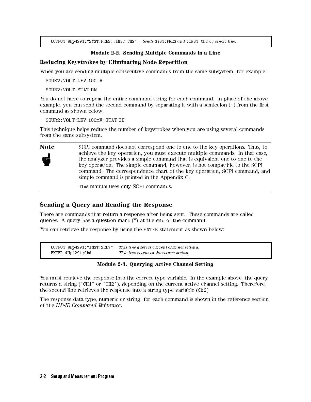
OUTPUT @Hp4291;"SYST:PRES;:INST CH2"
Sends
SYST:PRES
and
:INST CH2
by single line.
Module 2-2. Sending Multiple Commands in a Line
Reducing Keystrokes by Eliminating Node Repetition
When you are sending multiple consecutive commands from the same subsystem, for example:
SOUR2:VOLT:LEV 100mV
SOUR2:VOLT:STAT ON
You do not have to repeat the entire command string for each command. In place of the above
example, you can send the second command by separating it with a semicolon (;) from the rst
command as shown below:
SOUR2:VOLT:LEV 100mV;STAT ON
This technique helps reduce the number of keystrokes when you are using several commands
from the same subsystem.
Note
SCPI command does not correspond one-to-one to the key operations. Thus,to
achieve the key operation, you must execute multiple commands
. In that case,
the analyzer provides a simple command that is equivalent one-to-one to the
key operation. The simple command, however, is not compatible to the SCPI
command. The correspondence chart of the key operation, SCPI command, and
simple command is printed in the Appendix C.
This manual uses only SCPI commands.
Sending a Query and Reading the Response
There are commands that return a response after being sent. These commands are called
queries. A query has a question mark (?) at the end of the command.
You can retrieve the response by using the
OUTPUT @Hp4291;"INST:SEL?"
ENTER @Hp4291;Ch$
This line queries current channel setting.
This line retrieves the return string.
ENTER
statement as shown below:
Module 2-3. Querying Active Channel Setting
You must retrieve the response into the correct type variable
returns a string (\
CH1
"or\
CH2
"), depending on the current active channel setting. Therefore
the second line retrieves the response into a string type variable (
. In the example above, the query
Ch$
).
,
The response data type, numeric or string, for each command is shown in the reference section
of the
HP-IB Command Reference
.
2-2 Setup and Measurement Program
Page 39

Automating the Impedance Measurement Procedure
This section describes the sample program modules and equivalent commands for setting up the
analyzer using the following functions:
1. Setting the active channel
2. Setting stimulus.
3. Performing calibration.
4. Setting port extension and electrical length.
5. Performing xture compensation.
6. Setting measurement parameter.
7. Setting display format.
8. Setting dc bias.
9. Triggering a measurement.
10. Setting scale and reference.
11. Getting measured data to controller.
Figure 2-1 shows corresponding settings on the display of the analyzer to the above list.
Figure 2-1. Setting Parameters
1. Setting the Active Channel
To begin setting up the analyzer, specify the active channel rst because this aects all other
settings.
OUTPUT @Hp4291;"INST CH1"
Module 2-4. Setting the Measurement Mode and Active Channel
Sets the active channel to channel 1.
Setup and Measurement Program 2-3
Page 40

2. Setting Stimulus
The analyzer has four sweep sources. This section provides an example module for the
following settings:
Setting frequency sweep.
Setting OSC level sweep.
Setting dc voltage sweep. (Option 001 only)
Setting dc current sweep. (Option 001 only)
Setting Frequency Sweep Range and Level
To use a frequency sweep source, you must turn o the OSC level sweep, dc voltage sweep, and
dc current sweep.
OUTPUT @Hp4291;"SOUR1:VOLT:MODE FIX"
OUTPUT @Hp4291;"SOUR2:VOLT:MODE FIX"
OUTPUT @Hp4291;"SOUR2:CURR:MODE FIX"
OUTPUT @Hp4291;"SENS:FREQ:MODE SWE"
OUTPUT @Hp4291;"SENS:FREQ:STAR 100MHz;STOP 200MHz"
OSC level sweep is o.
dc voltage sweep is o.
dc current sweep is o.
Frequency sweep is on.
Sets frequency range from 100 to 200 MHz.
Module 2-5. Setting Frequency Sweep
To set the OSC level of the frequency sweep:
OUTPUT @Hp4291;"SOUR1:VOLT 400mV"
Sets the OSC level to 400 mV.
Module 2-6. Setting OSC Level
Related HP-IB Commands
You can set the log frequency sweep mode by sending both of the following commands (the
setting changes after both commands are executed):
SENS:SWE:SPAC LOG
DISP:TRAC:X:SPAC LOG
Selects log frequency sweep mode.
Sets the display to log format for x-axis.
To set back to the linear sweep:
SENS:SWE:SPAC LIN
DISP:TRAC:X:SPAC LIN
Selects linear frequency sweep mode.
Sets the display to linear format for x-axis.
Setting OSC Level Sweep
You can sweep by output level. To set an OSC level sweep:
OUTPUT @Hp4291;"SENS:FREQ:MODE FIX"
OUTPUT @Hp4291;"SOUR2:VOLT:MODE FIX"
OUTPUT @Hp4291;"SOUR2:CURR:MODE FIX"
OUTPUT @Hp4291;"SOUR1:VOLT:MODE SWE"
OUTPUT @Hp4291;"SOUR1:VOLT:STAR 0.5V;STOP 20V"
OUTPUT @Hp4291;"SOUR2:FREQ 100MHz"
Frequency sweep is o.
dc voltage sweep is o.
dc current sweep is o.
OSC level sweep is on.
Sets sweep range from 0.5 V to 20 V
Sets the CW frequency to 100 MHz.
Module 2-7. Setting OSC Level Sweep
2-4 Setup and Measurement Program
.
Page 41

Related HP-IB Commands
You can set the log sweep mode for OSC level sweep by sending both of the following
commands (the setting changes after both commands are executed):
SOUR1:SWE:SPAC LOG
DISP:TRAC:X:SPAC LOG
Selects log OSC level sweep.
Sets the display to log format for x-axis.
To set back to the linear sweep:
SOUR1:SWE:SPAC LIN
DISP:TRAC:X:SPAC LIN
Selects linear OSC level sweep mode.
Sets the display to linear format for x-axis.
You can change the sweep direction by using one of the following commands:
SOUR1:SWE:DIR DOWN
SOUR1:SWE:DIR UP
Sets the sweep direction from higher to lower level sweep.
Sets the sweep direction from lower to higher level sweep.
Setting dc Voltage Sweep (Option 001 Only)
You can sweep by the dc bias level:
OUTPUT @Hp4291;"SENS:FREQ:MODE FIX"
OUTPUT @Hp4291;"SOUR1:VOLT:MODE FIX"
OUTPUT @Hp4291;"SOUR2:CURR:MODE FIX"
OUTPUT @Hp4291;"SOUR2:VOLT:MODE SWE"
OUTPUT @Hp4291;"SOUR2:VOLT:STAR 0.5V;STOP 20V"
OUTPUT @Hp4291;"SOUR2:FREQ 100MHz"
OUTPUT @Hp4291;"SOUR2:VOLT:STAT ON"
Frequency sweep is o.
OSC level sweep is o.
dc current Sweep is o.
dc voltage sweep is on.
Sets sweep range from 0 V to 20 V.
Sets the CW frequency to 100 MHz.
Turns on dc bias.
Module 2-8. Setting dc Voltage Sweep
Related HP-IB Commands
You can set the log sweep mode for dc bias sweep by sending both of the following
commands (the setting changes after both commands are executed):
SOUR2:SWE:SPAC LOG
DISP:TRAC:X:SPAC LOG
Selects log dc bias level sweep.
Sets the display to log format for x-axis
.
To set back to the linear sweep:
SOUR2:SWE:SPAC LIN
DISP:TRAC:X:SPAC LIN
Selects linear dc bias sweep mode.
Sets the display to linear format for x-axis.
You can change the sweep direction by using one of the following commands:
SOUR2:SWE:DIR DOWN
SOUR2:SWE:DIR UP
Sets the sweep direction from higher to lower level sweep
Sets the sweep direction from lower to higher level sweep.
Setting dc Current Sweep (Option 001 Only)
To sweep dc current level:
.
Setup and Measurement Program 2-5
Page 42

OUTPUT @Hp4291;"SENS:FREQ:MODE FIX"
OUTPUT @Hp4291;"SOUR1:VOLT:MODE FIX"
OUTPUT @Hp4291;"SOUR2:VOLT:MODE FIX"
OUTPUT @Hp4291;"SOUR2:CURR:MODE SWE"
OUTPUT @Hp4291;"SOUR2:CURR:STAR 0A;STOP 100mA"
OUTPUT @Hp4291;"SOUR2:FREQ 100MHz"
OUTPUT @Hp4291;"SOUR2:CURR:STAT ON"
Module 2-9. Setting dc Current Sweep
3. Performing Calibration
See \Sample Program: Performing Calibration" in Chapter 4 for the calibration program.
Checking Calibration State
To check if calibration is currently turned on:
Frequency sweep is o.
OSC level sweep is o.
dc voltage sweep is o.
dc current sweep is on.
Sets sweep range from 0 A to 100 mA.
Sets the CW frequency to 100 MHz.
Turns ON the dc bias.
OUTPUT @Hp4291;"SENS:CORR1:STAT?"
ENTER @Hp4291;Stat
IF NOT Stat THEN PRINT "Calibration was not performed!"
Module 2-10. Checking Calibration State
Queries the current calibration status.
2-6 Setup and Measurement Program
Page 43

4. Setting Port Extension and Electrical Length
You have to set the port extension to remove the phase shift error from the test head to the
xture electrode before performing a xture compensation.
When a standard xture of the analyzer is connected, you can set the length by specifying the
xture name as shown below:
OUTPUT @Hp4291;"SYST:FIXT HP16191"
Sets the electrical length for the HP 16191A.
Module 2-11. Selecting the Connected Fixture
Related HP-IB Command
To select a dierent xture for the port extension setting:
SYST:FIXT HP16192
SYST:FIXT HP16193
SYST:FIXT UDEF
Set the electrical length for the HP 16192A.
Set the electrical length for the HP 16193A.
Set the electrical length for the user xture. (See below.)
You can also set the port extension by using the following command:
SENS:CORR1:EDEL
value
Set the electrical delay time due to the extension of the
port. [s]
You can dene your own xture as a user xture by entering the electrical length data and
label. The following module denes the HP 16092A xture as a user xture:
OUTPUT @Hp4291;"SYST:FIXT:DIST 0.0034"
OUTPUT @Hp4291;"SYST:FIXT:LAB '16092A'"
OUTPUT @Hp4291;"SYST:FIXT:SAVE"
Sets the electrical length for the HP 16092A.(0.34cm)
Sets label.
Saves the dened user xture data into SRAM.
Module 2-12. Setting the User Fixture
5. Performing Fixture Compensation
Performing xture compensation eliminates additional error from the test head to the electrode
of xture.
Before performing a xture compensation, you have to note the following things:
Calibration must be performed.
dc bias must be turned o.
Port extension is set if it required.
If user calibration is selected, you must select user compensation. The following module
detects automatically which calibration mode is selected, then sets the user compensation if the
user calibration is selected.
OUTPUT @Hp4291;"SENS:CORR1:COLL:FPO?"
ENTER @Hp4291;Cal_stat$
IF Cal_stat$="USER" THEN
OUTPUT @Hp4291;"SENS:CORR2:COLL:FPO USER"
Queries current calibration mode is FIXed or USER.
Retrieves a query response.
If user calibration is selected,
sets to the user compensation mode.
END IF
Module 2-13. Checking Calibration Mode (Fixed or User)
Setup and Measurement Program 2-7
Page 44
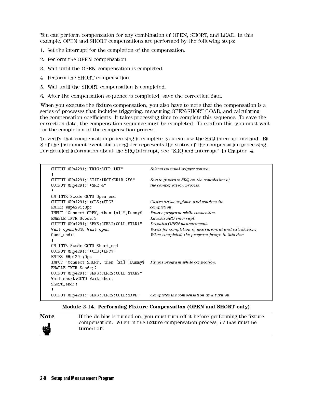
You can perform compensation for any combination of OPEN, SHORT, and LOAD. In this
example, OPEN and SHORT compensations are performed by the following steps:
1. Set the interrupt for the completion of the compensation.
2. Perform the OPEN compensation.
3. Wait until the OPEN compensation is completed.
4. Perform the SHORT compensation.
5. Wait until the SHORT compensation is completed.
6. After the compensation sequence is completed, save the correction data.
When you execute the xture compensation, you also have to note that the compensation is a
series of processes that includes triggering, measuring OPEN/SHORT/LOAD, and calculating
the compensation coecients. It takes processing time to complete this sequence.To save the
correction data, the compensation sequence must be completed. To conrm this, you must wait
for the completion of the compensation process.
To verify that compensation processing is complete, you can use the SRQ interrupt method. Bit
8 of the instrument event status register represents the status of the compensation processing.
For detailed information about the SRQ interrupt, see \SRQ and Interrupt" in Chapter 4.
OUTPUT @Hp4291;"TRIG:SOUR INT"
!
OUTPUT @Hp4291;"STAT:INST:ENAB 256"
OUTPUT @Hp4291;"*SRE 4"
!
ON INTR Scode GOTO Open_end
OUTPUT @Hp4291;"*CLS;*OPC?"
ENTER @Hp4291;Opc
INPUT "Connect OPEN, then [x1]",Dummy$
ENABLE INTR Scode;2
OUTPUT @Hp4291;"SENS:CORR2:COLL STAN1"
Wait_open:GOTO Wait_open
Open_end:!
!
ON INTR Scode GOTO Short_end
OUTPUT @Hp4291;"*CLS;*OPC?"
ENTER @Hp4291;Opc
INPUT "Connect SHORT, then [x1]",Dummy$
ENABLE INTR Scode;2
OUTPUT @Hp4291;"SENS:CORR2:COLL STAN2"
Wait_short:GOTO Wait_short
Short_end:!
!
OUTPUT @Hp4291;"SENS:CORR2:COLL:SAVE"
Module 2-14. Performing Fixture Compensation (OPEN and SHORT only)
Note
If the dc bias is turned on, you must turn o it before performing the xture
compensation. When in the xture compensation process, dc bias must be
turned o.
Selects internal trigger source.
Sets to generate SRQ on the completion of
the compensation process.
Clears status register, and conrm its
completion.
Pauses program while connection.
Enables SRQ interrupt.
Executes OPEN measurement.
Waits for completion of measurement and calculation.
When completed, the program jumps to this line.
Pauses program while connection.
Completes the compensation and turn on.
2-8 Setup and Measurement Program
Page 45

6. Setting Measurement Parameter
To set the measurement parameter, perform the following steps:
1. Set the conversion mode setting. (O for the impedance measurement. On for the
admittance or reection coecient measurement.)
2. Select the measurement parameter.
For example, select impedance as a parameter as follows:
OUTPUT @Hp4291;"CALC:MATH:STAT OFF"
OUTPUT @Hp4291;"CALC:FORM MLIN"
Selects impedance. (No conversion)
SelectsjZj.
Module 2-15. Setting Measurement Parameter
The measurement parameter, display format, and scale settings are processed after the
measurement. Therefore, you can change these settings after the measurement is triggered.
For example, when you need to measure more than two parameters, trigger once, then change
the parameter from the present one to another parameter.
Related HP-IB Command
Impedance
To select the impedance measurement parameter, execute the following command rst:
CALC:MATH:STAT OFF
Select impedance by turning o the conversion.
Then select the parameter by using one of the following commands:
CALC:FORM MLIN
CALC:FORM REAL
CALC:FORM IMAG
CALC:FORM PHAS
CALC:FORM CP
CALC:FORM CS
CALC:FORM LP
CALC:FORM LS
CALC:FORM D
CALC:FORM Q
CALC:FORM RP
CALC:FORM RS
Impedance,jZ
Resistance,R
Reactance,X
Phase,
C
C
L
L
z
P
S
P
S
D
Q
R
P
R
S
j
Admittance
To select the admittance measurement parameter, execute the following command rst:
CALC:MATH:NAME ADM;STAT ON
Selects admittance.
Then select the parameter by using one of the following commands:
CALC:FORM MLIN
CALC:FORM REAL
CALC:FORM IMAG
CALC:FORM PHAS
Admittance,jY
j
Conductance,G
Susceptance,B
Phase,
y
Reection Coecients
To select the reection coecient parameter, execute the following command rst:
CALC:MATH:NAME RCO;STAT ON
Selects reection coecient.
Setup and Measurement Program 2-9
Page 46

Then select the parameter by using one of the following commands:
CALC:FORM MLIN
CALC:FORM REAL
CALC:FORM IMAG
CALC:FORM PHAS
Reection Coecient,j0
Reection Coecient,j0xj
Reection Coecient,j0yj
Phase,
0
j
7. Setting Display Format
To set the display format, perform the following steps:
1. Select the grid to rectangle, Smith, polar, admittance, or complex plane.
2. Select parameter:
a. Select a linear or log scale for the rectangular grid.
b. If you select the Smith, polar, admittance chart, or complex plane, choose the complex
format to include phase information.
The following example sets the format to log format:
OUTPUT @Hp4291;"DISP:TRAC1:GRAT:FORM RECT"
OUTPUT @Hp4291;"DISP:TRAC1:Y:SPAC LOG"
Selects the rectangular grid.
Sets the log scale.
Module 2-16. Setting a Log Format
Related HP-IB Command
You can set the display format by sending the both of the listed commands for each format:
Linear format
DISP:TRAC1:GRAT:FORM RECT
DISP:TRAC1:Y:SPAC LIN
Selects rectangular grid.
Selects linear format.
Log format
DISP:TRAC1:GRAT:FORM RECT
DISP:TRAC1:Y:SPAC LOG
Selects rectangular grid.
Selects log format.
Polar chart
CALC:FORM COMP
DISP:TRAC1:GRAT:FORM POL
Select complex format.
Select polar chart grid.
Smith chart
CALC:FORM COMP
DISP:TRAC1:GRAT:FORM SMIT
Select complex format.
Select Smith chart grid.
Admittance chart
CALC:FORM COMP
DISP:TRAC1:GRAT:FORM ADM
Select complex format.
Select admittance chart grid.
Complex Plane
CALC:FORM COMP
DISP:TRAC1:GRAT:FORM CPL
Select complex.
Select complex plane grid.
2-10 Setup and Measurement Program
Page 47

8. Setting dc Bias (Option 001 Only)
When you use a frequency sweep or OSC level sweep, you can apply a dc bias to the DUT.
OUTPUT @Hp4291;"SOUR2:VOLT:ALC ON"
OUTPUT @Hp4291;"SOUR2:VOLT:LEV 10V"
OUTPUT @Hp4291;"SOUR2:CURR:LEV 100mA"
OUTPUT @Hp4291;"SOUR2:VOLT:STAT ON"
Module 2-17. Setting dc Bias (Voltage)
Related HP-IB Command
To set the dc current instead of dc voltage:
SOUR2:CURR:ALC ON
SOUR2:CURR:LEV 10mA;STAT ON
Selects dc current bias.
Sets dc bias current to 10 mA and turns on.
Selects dc voltage bias.
Sets dc bias voltage to 10 V.
Sets current compliance to 100 mA.
Turns on the dc bias.
Setup and Measurement Program 2-11
Page 48
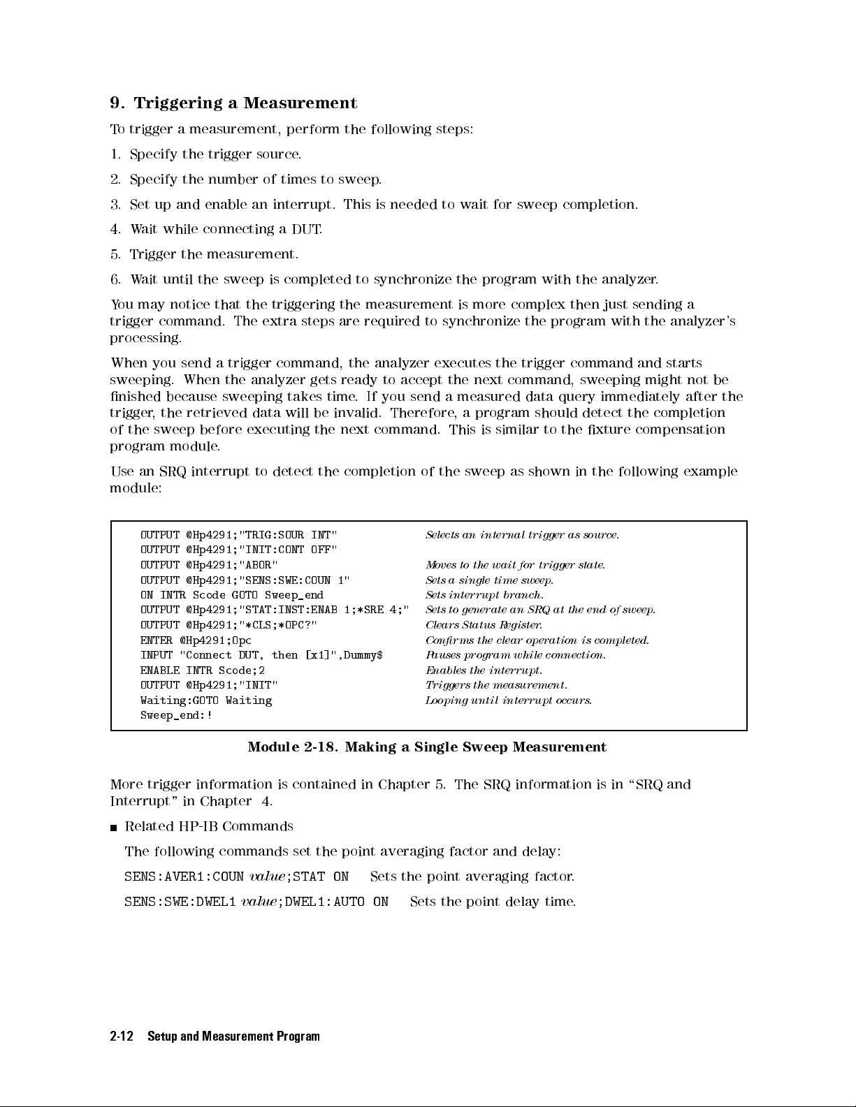
9. Triggering a Measurement
To trigger a measurement, perform the following steps:
1. Specify the trigger source.
2. Specify the number of times to sweep.
3. Set up and enable an interrupt. This is needed to wait for sweep completion.
4. Wait while connecting a DUT.
5. Trigger the measurement.
6. Wait until the sweep is completed to synchronize the program with the analyzer.
You may notice that the triggering the measurement is more complex then just sending a
trigger command. The extra steps are required to synchronize the program with the analyzer's
processing.
When you send a trigger command, the analyzer executes the trigger command and starts
sweeping. When the analyzer gets ready to accept the next command, sweeping might not be
nished because sweeping takes time. If you send a measured data query immediately after the
trigger, the retrieved data will be invalid. Therefore, a program should detect the completion
of the sweep before executing the next command. This is similar to the xture compensation
program module.
Use an SRQ interrupt to detect the completion of the sweep as shown in the following example
module:
OUTPUT @Hp4291;"TRIG:SOUR INT"
Selects an internal trigger as source.
OUTPUT @Hp4291;"INIT:CONT OFF"
OUTPUT @Hp4291;"ABOR"
OUTPUT @Hp4291;"SENS:SWE:COUN 1"
ON INTR Scode GOTO Sweep_end
OUTPUT @Hp4291;"STAT:INST:ENAB 1;*SRE 4;"
OUTPUT @Hp4291;"*CLS;*OPC?"
ENTER @Hp4291;Opc
INPUT "Connect DUT, then [x1]",Dummy$
ENABLE INTR Scode;2
OUTPUT @Hp4291;"INIT"
Waiting:GOTO Waiting
Moves to the wait for trigger state.
Sets a single time sweep.
Sets interrupt branch.
Sets to generate an SRQ at the end of sweep
Clears Status Register.
Conrms the clear operation is completed.
Pauses program while connection.
Enables the interrupt.
Triggers the measurement.
Looping until interrupt occurs.
.
Sweep_end:!
Module 2-18. Making a Single Sweep Measurement
More trigger information is contained in Chapter 5. The SRQ information is in \SRQ and
Interrupt" in Chapter 4.
Related HP-IB Commands
The following commands set the point averaging factor and delay:
SENS:AVER1:COUN
SENS:SWE:DWEL1
value
;STAT ON
value
;DWEL1:AUTO ON
Sets the point averaging factor.
Sets the point delay time.
2-12 Setup and Measurement Program
Page 49

10. Setting Scale and Reference
After triggering the measurement, you can change the scale setting to t the trace in a display.
OUTPUT @Hp4291;"DISP:TRAC:Y:AUTO ONCE"
Sets optimum scale setting.
Module 2-19. Automatic Scaling
11. Getting Measured Data to the Controller
After a measurement is completed, you probably want to get the measured data. To obtain a
specic point's data, use the marker search function. You can get the data by performing the
following steps:
1. Turn on the marker.
(You must turn on the marker rst to use a marker function.)
2. Move the marker to a specied value.
3. Query the marker value to get the measured data to the controller.
The following example module gets a measured value at the specied frequency from the
analyzer:
OUTPUT @Hp4291;"DISP:TRAC:MARK:ALL:STAT ON"
OUTPUT @Hp4291;"CALC:EVAL:Y1:XPOS 100MHz"
OUTPUT @Hp4291;"CALC:EVAL:Y1:DATA?"
ENTER @Hp4291;Mkr_value,Dummy,Mkr_f
Turns on the marker.
Moves the marker to the specied frequency, 100 MHz.
Queries the measured data at the marker position.
Retrieves the queried marker value to a variable.
Module 2-20. Getting Marker Measurement Data
Related HP-IB Commands
The following commands are also used for controlling the marker
.
To clear the marker:
DISP:TRAC1:MARK1:ALL DEF
Clears all markers from display.
To use a marker search function:
CALC:EVAL:Y1:XPOS:MAX
CALC:EVAL:Y1:XPOS:MIN
CALC:EVAL:Y1:XPOS:TARG
CALC:EVAL:Y1:XPOS:PEAK
value
Searches for the maximum value.
Searches for the minimum value.
Searches for the target value.
Searches for the peak.
The following commands return a marker value independently of the active channel
setting:
CALC:EVAL:Y1:DATA? {CH1|CH2}
Returns the marker value and its stimulus for channel
1 or 2, respectively.
You can also get the trace data train of the all measurement point instead of only the marker
value by accessing the trace data array. See Chapter 3 for information on the internal data
arrays and how to access them.
Setup and Measurement Program 2-13
Page 50
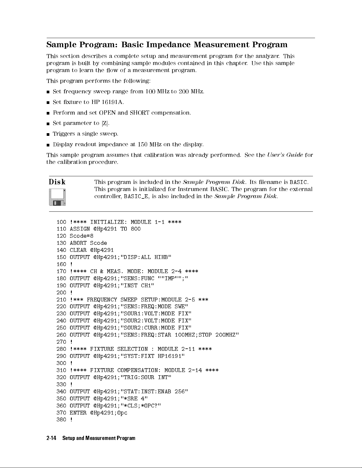
Sample Program: Basic Impedance Measurement Program
This section describes a complete setup and measurement program for the analyzer. This
program is built by combining sample modules contained in this chapter. Use this sample
program to learn the ow of a measurement program.
This program performs the following:
Set frequency sweep range from 100 MHz to 200 MHz.
Set xture to HP 16191A.
Perform and set OPEN and SHORT compensation.
Set parameter tojZj.
Triggers a single sweep.
Display readout impedance at 150 MHz on the display.
This sample program assumes that calibration was already performed. See the
the calibration procedure.
This program is included in the
Sample Program Disk
. Its lename is
This program is initialized for Instrument BASIC. The program for the external
controller,
BASIC_E
, is also included in the
Sample Program Disk
100 !**** INITIALIZE: MODULE 1-1 ****
110 ASSIGN @Hp4291 TO 800
120 Scode=8
130 ABORT Scode
140 CLEAR @Hp4291
150 OUTPUT @Hp4291;"DISP:ALL HIHB"
160 !
170 !**** CH & MEAS. MODE: MODULE 2-4 ****
180 OUTPUT @Hp4291;"SENS:FUNC ""IMP"";"
190 OUTPUT @Hp4291;"INST CH1"
200 !
210 !*** FREQUENCY SWEEP SETUP:MODULE 2-5 ***
220 OUTPUT @Hp4291;"SENS:FREQ:MODE SWE"
230 OUTPUT @Hp4291;"SOUR1:VOLT:MODE FIX"
240 OUTPUT @Hp4291;"SOUR2:VOLT:MODE FIX"
250 OUTPUT @Hp4291;"SOUR2:CURR:MODE FIX"
260 OUTPUT @Hp4291;"SENS:FREQ:STAR 100MHZ;STOP 200MHZ"
270 !
280 !**** FIXTURE SELECTION : MODULE 2-11 ****
290 OUTPUT @Hp4291;"SYST:FIXT HP16191"
300 !
310 !**** FIXTURE COMPENSATION: MODULE 2-14 ****
320 OUTPUT @Hp4291;"TRIG:SOUR INT"
330 !
340 OUTPUT @Hp4291;"STAT:INST:ENAB 256"
350 OUTPUT @Hp4291;"*SRE 4"
360 OUTPUT @Hp4291;"*CLS;*OPC?"
370 ENTER @Hp4291;Opc
380 !
User's Guide
BASIC
.
for
.
2-14 Setup and Measurement Program
Page 51

390 ON INTR Scode GOTO Open_end
400 INPUT "CONNECT OPEN, THEN [RETURN]",A
410 ENABLE INTR Scode;2
420 OUTPUT @Hp4291;"SENS:CORR2:COLL STAN1"
430 Wait_open:GOTO Wait_open
440 Open_end:!
450 !
460 ON INTR Scode GOTO Short_end
470 OUTPUT @Hp4291;"*CLS;*OPC?"
480 ENTER @Hp4291;Opc
490 INPUT "CONNECT SHORT, THEN [RETURN]",A
500 ENABLE INTR Scode;2
510 OUTPUT @Hp4291;"SENS:CORR2:COLL STAN2"
520 Wait_short:GOTO Wait_short
530 Short_end:!
540 !
550 OUTPUT @Hp4291;"SENS:CORR2:COLL:SAVE"
560 !
570 !**** SET |Z| AS parameter: MODULE 2-15 ****
580 OUTPUT @Hp4291;"CALC:MATH:STAT OFF"
590 OUTPUT @Hp4291;"CALC:FORM MLIN"
600 !
610 !**** SET LIN FORMAT: MODULE 2-16 ****
620 OUTPUT @Hp4291;"DISP:TRAC1:GRAT:FORM RECT"
630 OUTPUT @Hp4291;"DISP:TRAC1:Y:SPAC LIN"
640 !
650 !**** TRIGGER: MODULE 2-18 ****
660 OUTPUT @Hp4291;"TRIG:SOUR INT"
670 OUTPUT @Hp4291;"INIT:CONT OFF"
680 OUTPUT @Hp4291;"ABOR"
690 OUTPUT @Hp4291;"SENS:SWE:COUN 1"
700 ON INTR Scode GOTO Sweep_end
710 OUTPUT @Hp4291;"STAT:INST:ENAB 1;*SRE 4"
720 OUTPUT @Hp4291;"*CLS;*OPC?"
730 ENTER @Hp4291;Opc
740 INPUT "CONNECT DUT, THEN PRESS [RETURN]",A
750 ENABLE INTR Scode;2
760 OUTPUT @Hp4291;"INIT"
770 Waiting:GOTO Waiting
780 Sweep_end:!
790 !
800 !**** AUTO SCALING: MODULE 2-19 ****
810 OUTPUT @Hp4291;"DISP:TRAC:Y:AUTO ONCE"
820 !
830 !**** MARKER FUNCTION: MODULE 2-20 ****
840 OUTPUT @Hp4291;"DISP:TRAC:MARK1:ALL:STAT ON"
850 OUTPUT @Hp4291;"CALC:EVAL:Y1:XPOS 150MHZ"
860 OUTPUT @Hp4291;"CALC:EVAL:Y1:DATA?"
870 ENTER @Hp4291;Mkr_value,Dummy,Mkr_f
880 PRINT TABXY(1,1),Mkr_value;"[OHM] ",TABXY(1,2),Mkr_f;"[Hz]"
890 !
900 END
Setup and Measurement Program 2-15
Page 52

Automating the Permittivity Measurement (Option 002 Only)
When Option 002 (Add Material Measurement Firmware) is installed in the analyzer, you can
measure the permittivity parameters of the materials directly.
As shown below, the permitivity measurement procedure is similar to the impedance
measurement procedure previously described. However, when performing permittivity
measurements, the sample modules shown in bold are dierent from the impedance
measurement procedure. This section describes the sample program modules that are dierent.
You can build a control program by combining the sample program module in this section with
the impedance measurement program.
1. Setting the active channel
2. Setting stimulus
3. Performing calibration
4.
Selecting xture
5.
Performing xture compensation
6.
Setting MUT thickness
7.
Setting measurement parameter
8. Setting display format
9. Setting dc bias
10. Triggering a measurement
11. Setting scale and reference.
12. Getting measured data to controller
4. Selecting Fixture
To make a permittivity measurement, you must select a permittivity xture as shown below:
OUTPUT @Hp4291;"SYST:FIXT HP16453"
Selects the HP 16453A.
Module 2-21. Selecting the Connected Fixture
5. Performing Fixture Compensation
In the permittivity measurement, you must perform all OPEN/SHORT/LO
AD compensations
at the permittivity xture electrodes.For the LOAD compensation, the analyzer must know
the LOAD's thickness and permittivity. The permittivity of the LOAD furnished with the HP
16453A dielectric material xture is preset, but the thickness must be entered manually.
OUTPUT @Hp4291;"SENS:CORR2:CKIT2:STAN6:THIC 3.01mm"
OUTPUT @Hp4291;"SENS:CORR2:CKIT2:SAVE"
OUTPUT @Hp4291;"SENS:CORR2:CKIT2 UDEF"
Setting LOAD thickness.
Storing data into a non-volatile memory.
Selects the dened calibration kit.
Module 2-22. Modifying Permittivity Compensation Kit
The xture compensation procedure is similar to the impedance measurement, the dierence is
that it requires all OPEN/SHORT/LOAD compensations.
2-16 Setup and Measurement Program
Page 53
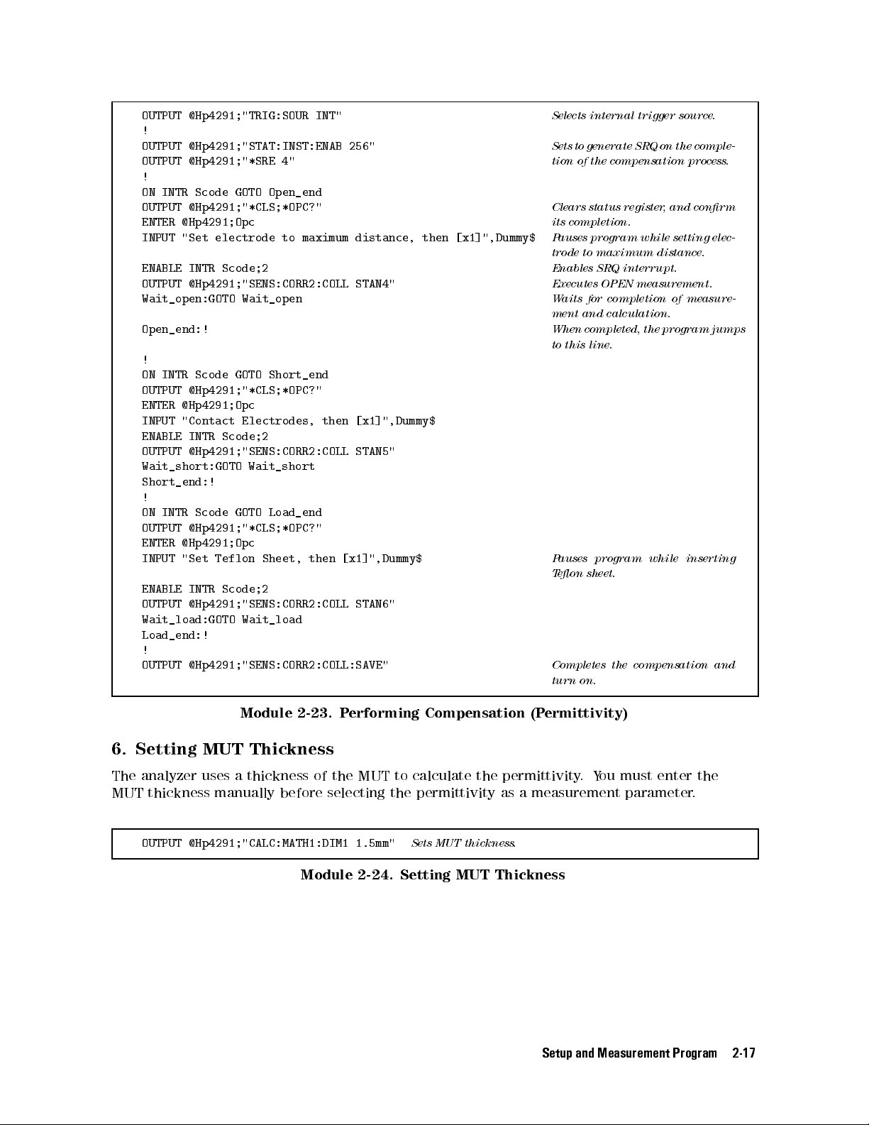
OUTPUT @Hp4291;"TRIG:SOUR INT"
!
OUTPUT @Hp4291;"STAT:INST:ENAB 256"
OUTPUT @Hp4291;"*SRE 4"
!
ON INTR Scode GOTO Open_end
OUTPUT @Hp4291;"*CLS;*OPC?"
ENTER @Hp4291;Opc
INPUT "Set electrode to maximum distance, then [x1]",Dummy$
ENABLE INTR Scode;2
OUTPUT @Hp4291;"SENS:CORR2:COLL STAN4"
Wait_open:GOTO Wait_open
Open_end:!
!
ON INTR Scode GOTO Short_end
OUTPUT @Hp4291;"*CLS;*OPC?"
ENTER @Hp4291;Opc
INPUT "Contact Electrodes, then [x1]",Dummy$
ENABLE INTR Scode;2
OUTPUT @Hp4291;"SENS:CORR2:COLL STAN5"
Wait_short:GOTO Wait_short
Short_end:!
!
ON INTR Scode GOTO Load_end
OUTPUT @Hp4291;"*CLS;*OPC?"
ENTER @Hp4291;Opc
INPUT "Set Teflon Sheet, then [x1]",Dummy$
ENABLE INTR Scode;2
OUTPUT @Hp4291;"SENS:CORR2:COLL STAN6"
Wait_load:GOTO Wait_load
Load_end:!
!
OUTPUT @Hp4291;"SENS:CORR2:COLL:SAVE"
Selects internal trigger source.
Sets to generate SRQ on the comple-
tion of the compensation process.
Clears status register, and conrm
its completion.
Pauses program while setting elec-
trode to maximum distance.
Enables SRQ interrupt.
Executes OPEN measurement.
Waits for completion of measure-
ment and calculation.
When completed, the program jumps
to this line.
Pauses program while inserting
Teon sheet.
Completes the compensation and
turn on.
Module 2-23. Performing Compensation (Permittivity)
6. Setting MUT Thickness
The analyzer uses a thickness of the MUT to calculate the permittivity
.You must enter the
MUT thickness manually before selecting the permittivity as a measurement parameter
OUTPUT @Hp4291;"CALC:MATH1:DIM1 1.5mm"
Sets MUT thickness.
Module 2-24. Setting MUT Thickness
Setup and Measurement Program 2-17
.
Page 54

7. Setting Measurement Parameter
To select a permittivity parameter, perform the following steps:
1. Turn the permittivity conversion on.
2. Select the measurement parameter.
For example, select the permittivity as follows:
OUTPUT @Hp4291;"CALC:MATH1:NAME DCO;STAT ON"
OUTPUT @Hp4291;"CALC:FORM REAL"
Selects the permittivity conversion.
Selects
"r'.
Module 2-25. Setting Measurement Parameter (Permittivity)
Related HP-IB Commands
Permittivity
To select the permittivity measurement parameter, execute the following command rst:
CALC:MATH:NAME DCO;STAT ON
Selects permittivity.
Then select the parameter by using one of the following commands:
CALC:FORM MLIN
CALC:FORM REAL
CALC:FORM LFAC
CALC:FORM LTAN
Absolute value of complex dielectric constant,j"
Dielectric constant,
Dielectric loss index,
constant)
Dielectric dissipation factor,
"
' (real part of complex dielectric constant)
r
"
'' (imaginary part of complex dielectric
r
00
"
tan(=
r
)
0
j
"
j
r
j
r
Cole-Cole Plot
Plotting a trace of
"
' on X axis and
r
"
'' on Y axis is called a Cole-Cole plot that is used to
r
analyze a evaluation of the hi-polymer materials.To display the Cole-Cole plot, use the
following:
OUTPUT @Hp4291;"CALC:MATH:NAME DCO;STAT ON"
OUTPUT @Hp4291;"CALC:FORM MLIN"
OUTPUT @Hp4291;"CALC:FORM COMP"
OUTPUT @Hp4291;"DISP:TRAC1:GRAT:FORM CPL"
Module 2-26. Displaying Cole-Cole Plot
2-18 Setup and Measurement Program
Turns on the dielectric constant conversion.
Selectingj"jis ignored in the complex plane.
Select complex form.
Select complex plane grid for displaying Cole-Cole plot.
Page 55
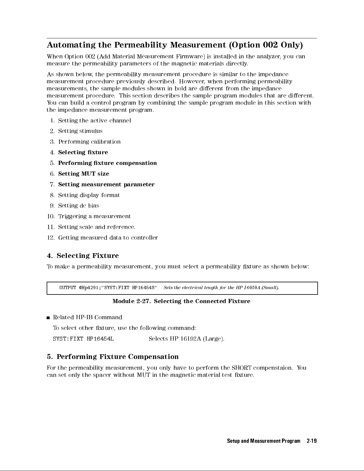
Automating the Permeability Measurement (Option 002 Only)
When Option 002 (Add Material Measurement Firmware) is installed in the analyzer, you can
measure the permeability parameters of the magnetic materials directly.
As shown below, the permeability measurement procedure is similar to the impedance
measurement procedure previously described. However, when performing permeability
measurements, the sample modules shown in bold are dierent from the impedance
measurement procedure. This section describes the sample program modules that are dierent.
You can build a control program by combining the sample program module in this section with
the impedance measurement program.
1. Setting the active channel
2. Setting stimulus
3. Performing calibration
4.
Selecting xture
5.
Performing xture compensation
6.
Setting MUT size
7.
Setting measurement parameter
8. Setting display format
9. Setting dc bias
10. Triggering a measurement
11. Setting scale and reference.
12. Getting measured data to controller
4. Selecting Fixture
To make a permeability measurement, you must select a permeability xture as shown below:
OUTPUT @Hp4291;"SYST:FIXT HP16454S"
Sets the electrical length for the HP 16454A (Small).
Module 2-27. Selecting the Connected Fixture
Related HP-IB Command
To select other xture, use the following command:
SYST:FIXT HP16454L
Selects HP 16192A (Large).
5. Performing Fixture Compensation
For the permeability measurement, you only have to perform the SHORT compenstaion. You
can set only the spacer without MUT in the magnetic material test xture.
Setup and Measurement Program 2-19
Page 56
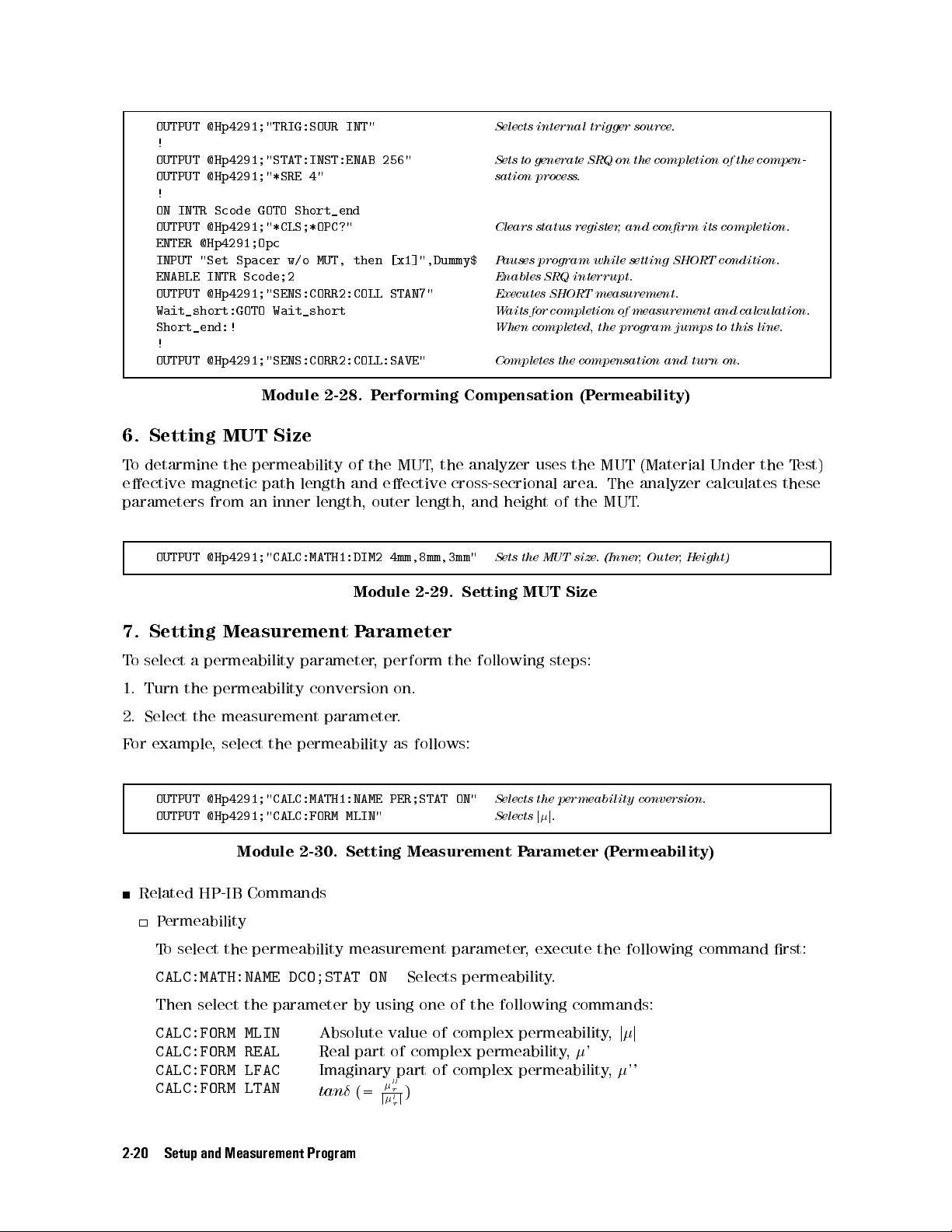
OUTPUT @Hp4291;"TRIG:SOUR INT"
!
OUTPUT @Hp4291;"STAT:INST:ENAB 256"
OUTPUT @Hp4291;"*SRE 4"
!
ON INTR Scode GOTO Short_end
OUTPUT @Hp4291;"*CLS;*OPC?"
ENTER @Hp4291;Opc
INPUT "Set Spacer w/o MUT, then [x1]",Dummy$
ENABLE INTR Scode;2
OUTPUT @Hp4291;"SENS:CORR2:COLL STAN7"
Wait_short:GOTO Wait_short
Short_end:!
!
OUTPUT @Hp4291;"SENS:CORR2:COLL:SAVE"
Module 2-28. Performing Compensation (Permeability)
6. Setting MUT Size
Selects internal trigger source.
Sets to generate SRQ on the completion of the compen-
sation process.
Clears status register, and conrm its completion.
Pauses program while setting SHORT condition.
Enables SRQ interrupt.
Executes SHORT measurement.
Waits for completion of measurement and calculation.
When completed, the program jumps to this line.
Completes the compensation and turn on.
To detarmine the permeability of the MUT
, the analyzer uses the MUT (Material Under the T
est)
eective magnetic path length and eective cross-secrional area. The analyzer calculates these
parameters from an inner length, outer length, and height of the MUT
OUTPUT @Hp4291;"CALC:MATH1:DIM2 4mm,8mm,3mm"
Sets the MUT size. (Inner, Outer, Height)
.
Module 2-29. Setting MUT Size
7. Setting Measurement Parameter
To select a permeability parameter, perform the following steps:
1. Turn the permeability conversion on.
2. Select the measurement parameter.
For example, select the permeability as follows:
OUTPUT @Hp4291;"CALC:MATH1:NAME PER;STAT ON"
OUTPUT @Hp4291;"CALC:FORM MLIN"
Selects the permeability conversion.
Selectsjj.
Module 2-30. Setting Measurement Parameter (Permeability)
Related HP-IB Commands
Permeability
To select the permeability measurement parameter, execute the following command rst:
CALC:MATH:NAME DCO;STAT ON
Selects permeability.
Then select the parameter by using one of the following commands:
CALC:FORM MLIN
CALC:FORM REAL
CALC:FORM LFAC
CALC:FORM LTAN
Absolute value of complex permeability,j
Real part of complex permeability,'
Imaginary part of complex permeability,''
tan(=
00
r
)
0
j
j
r
j
2-20 Setup and Measurement Program
Page 57

Data Processing and Transfer
This chapter describes data processing and how to access the internal data arrays.
The following information is covered in this chapter:
Data arrays
Data transfer method
Sample program: compensation data transfer
Data Arrays
The analyzer has data arrays that contain the measurement data, error correction data, and
stimulus data. You can read or write data to these arrays using HP-IB commands
Figure 3-1 shows a simplied diagram of the data processing in the analyzer:
.
3
Figure 3-1. Simplied Data Processing Flow
Double lined boxes represents data arrays that hold intermediate or processed data. The
following section describes each of these data arrays
.
Data Processing and Transfer 3-1
Page 58

Raw Data Array
The raw data array stores the results of all the preceding data processing operations including
the correction by calibration data. The analyzer measures the voltage and current of a DUT
and converts them to impedance. The raw data array stores this converted impedance value
in a complex form (R and X). When you want to use your own compensation method for a
measurement data, 1) take out the raw data from the raw data array (see module 3-1), 2) apply
your compensation method to the taken out data, 3) enter compensated data into the data
array (module 3-2).
The following example module queries for raw data and retrieves it:
DIM Dat(1:201,1:2)
OUTPUT @Hp4291;"DATA? RAW"
Dene NOP22 for receiving complex data.
Query raw data array.
ENTER @Hp4291;Dat(*)
Module 3-1. Getting Raw Data Array
Related HP-IB Commands
The following command is used for setting data to the raw data array:
DATA RAW,
data
Sends data to the raw data array of the active channel.
Data Array
The results of error correction are stored in the data array as a complex form of impedance (R
and X). The error correction process reects the port extension and xture compensation for
the raw data array.
When you want impedance data in a complex format, use this array
.
The following example module sets data for the data array:
OUTPUT @Hp4291;"DATA DATA,";Dat(*)
Sets data to data array.
Module 3-2. Setting Data Array Data
Related HP-IB Commands
The following command is used to query the data array data:
DATA? DATA
Queries data in data array of the active channel.
Data Trace Array
This is the array for the data being displayed. All post processing functions; formatting,
parameter setting, and data math are processed for the impedance data of the data array and
stored in this array. The units of the array readout depend on the current display paramter.
This data is the same data as listed by
4
Copy
NNNNNNNNNNNNNN
5
MORE
NNNNNNNNNNNNNNNNNNNNNNNNNNNNNNNNNNN
LIST VALUES
.
This data trace array is generally the most useful because it is the same information as that
seen on the display. When you want to use data with a selected parameter unit, use this array
The data trace array data is scalar data unless the Smith chart, polar chart, admittance chart,
or complex plane is selected as the display format. Then the data trace array holds data in a
complex form. Therefore, the imaginary part of the trace data array contains all ''0''.
3-2 Data Processing and Transfer
.
Page 59
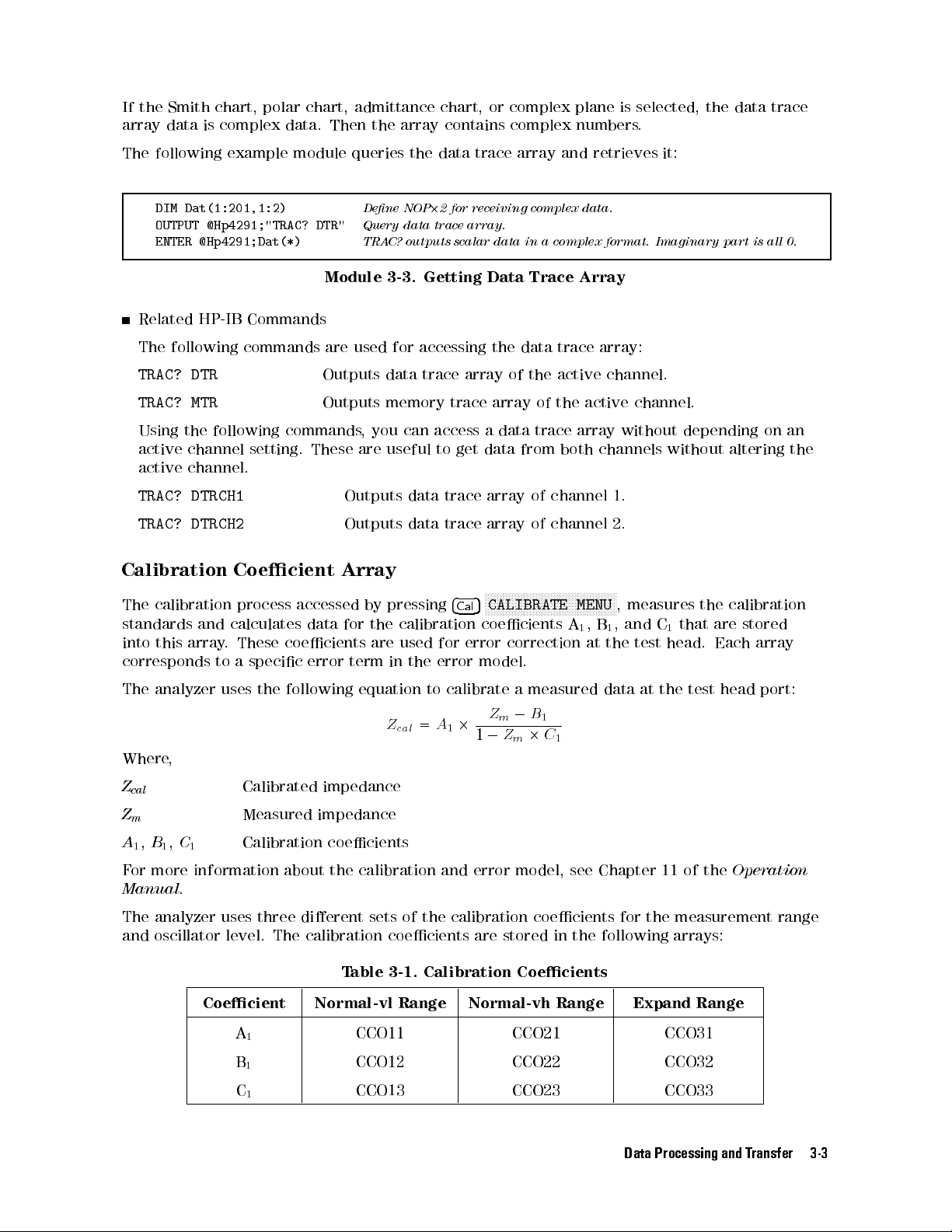
If the Smith chart, polar chart, admittance chart, or complex plane is selected, the data trace
array data is complex data. Then the array contains complex numbers.
The following example module queries the data trace array and retrieves it:
DIM Dat(1:201,1:2)
OUTPUT @Hp4291;"TRAC? DTR"
ENTER @Hp4291;Dat(*)
Dene NOP22 for receiving complex data.
Query data trace array.
TRAC? outputs scalar data in a complex format. Imaginary part is all 0.
Module 3-3. Getting Data Trace Array
Related HP-IB Commands
The following commands are used for accessing the data trace array:
TRAC? DTR
TRAC? MTR
Outputs data trace array of the active channel.
Outputs memory trace array of the active channel.
Using the following commands, you can access a data trace array without depending on an
active channel setting. These are useful to get data from both channels without altering the
active channel.
TRAC? DTRCH1
TRAC? DTRCH2
Outputs data trace array of channel 1.
Outputs data trace array of channel 2.
Calibration Coecient Array
NNNNNNNNNNNNNNNNNNNNNNNNNNNNNNNNNNNNNNNNNNNN
The calibration process accessed by pressing
4
5
CALIBRATE MENU
Cal
, measures the calibration
standards and calculates data for the calibration coecients A1,B1, and C1that are stored
into this array. These coecients are used for error correction at the test head. Each array
corresponds to a specic error term in the error model.
The analyzer uses the following equation to calibrate a measured data at the test head port:
Zm0
B
Z
=
A12
cal
10Z
1
2
C
m
1
Where,
Z
cal
Z
m
A1,
B1,
C
1
For more information about the calibration and error model, see Chapter 11 of the
Manual
.
Calibrated impedance
Measured impedance
Calibration coecients
Operation
The analyzer uses three dierent sets of the calibration coecients for the measurement range
and oscillator level. The calibration coecients are stored in the following arrays:
Table 3-1. Calibration Coecients
Coecient Normal-vl Range Normal-vh Range Expand Range
A
1
B
1
C
1
CCO11 CCO21 CCO31
CCO12 CCO22 CCO32
CCO13 CCO23 CCO33
Data Processing and Transfer 3-3
Page 60

All coecients are required for normal operation.
Accessing Arrays
If you want to enter calibration data from the controller to the calibration coecient array, the
analyzer must have previously done the calibration to enable the calibration data. To do this,
perform the following steps:
1. Execute a dummy calibration to validate the correction.
2. Send the new calibration coecients.
Note that the calibration coecients are a complex data.
Related HP-IB Commands
The following command is used for accessing the calibration coecient array:
DATA(?) CCO{11|12|13|21|22|23|31|32|33}
Sets (Outputs) the specied calibration
coecient array data of the active
channel.
Compensation Coecient Array
NNNNNNNNNNNNNNNNNNNNNNNNNNNNNNNNNNNNNNNNNNNN
The xture compensation process accessed by pressing
OPEN, SHORT, and/or LOAD and calculates data for compensation coecients A
4
5
FIXTURE COMPEN
Cal
, measures the
, and C
3,B3
that are stored into the compensation coecient array. Therefore, the xture compensation
array has three arrays.
The xture compensation coecients,A
, and C3depend on the combination of OPEN,
3,B3
SHORT, and LOAD (ON or OFF for each). The analyzer calculates three coecients using
dierent equations for the combination of OPEN/SHORT/LOAD (on/o). If you change the
combination of OPEN, SHORT,orLOAD (on/o), the analyzer calculates the coecients again
using the measured OPEN, SHORT, and/or LOAD data and sets new A
, and C3coecients
3,B3
into the compensation coecient arrays.
The analyzer uses the following equation to compensate calibrated data after port extension:
Z
comp
=
2
port
10Z
A
3
port
3
2
C
3
Z
0
B
Where,
Z
comp
Z
port
A3,
B
,
C
3
3
For more information on how the data is used to compensate for errors
Manual
.
Compensated impedance
Impedance after corrected a port extension to the calibration data
Compensation coecients
, see the
Operation
3
Accessing Arrays
If you want to use custom compensation data by sending correction data to the xture
compensation array from the controller, you have to turn on the xture compensation
by performing the xture compensation process. The
CMP
(or
Cmp
) notation shows that
compensation is activated. To do this, perform the following steps:
1. Execute a dummy compensation either OPEN, SHORT,orLOAD to turn on it.
2. Set new compensation data.
Note that the xture compensation coecients are complex data.
3-4 Data Processing and Transfer
Page 61

Note
After setting a new compensation data, do not change the compensation
settings, stimulus setting, or test head setting. Otherwise the analyzer
recalculates the xture compensation coecients and overwrites the arrays.
Related HP-IB Commands
The following commands are used for accessing the compensation data arrays:
DATA? CMP{1|2|3}
DATA CMP{1|2|3},
data
Outputs coecients A3,B3, and C3data, respectively.
Enters coecients A3,B3, and C3data, respectively into the
xture compensation array.
Monitor Array
The monitor array stores a level monitor value for all measurement points. The monitored level
data is stored when the level monitor function is turned on and has executed a sweep.
This array is read-only.
To get the level monitor data:
DIM Monitor(1:201)
OUTPUT @Hp4291;"CALC:EVAL:ON2 'ACV'"
Denes NOP size array for receiving data.
Turning on the level monitor,\AC-V".
:
: Insert Module 2-18 here.
:
OUTPUT @Hp4291;"DATA? MON"
Queries stimulus array.
ENTER @Hp4291;Monitor(*)
Module 3-4. Getting Level Monitor Data
Related HP-IB Commands
The following commands are used for accessing the level monitor data array
CALC:EVAL:ON2 "ACC"
CALC:EVAL:ON2 "DCV"
CALC:EVAL:ON2 "DCC"
CALC:EVAL:ON2 "OFF"
Monitors ac current level.
Monitors dc voltage level.
Monitors dc current level.
Turn o the level monitor.
Stimulus Array
The stimulus array contains the stimulus (x-axis) value for all displayed points.
DIM Stim(1:201)
OUTPUT @Hp4291;"DATA? SPAR"
Dene NOP size array for receiving data.
Query stimulus array.
ENTER @Hp4291;Stim(*)
Module 3-5. Getting Stimulus Array
Data Processing and Transfer 3-5
.
Page 62

Arrays for Memory Trace
When you store the trace data into the trace memory by sending the
command or by pressing
NNNNNNNNNNNNNNNNNNNNNNNNNNNNNNNNNNNNNNNNNNN
DATA
!
MEMORY
, the data array data is stored into the memory array.
TRAC:COPY TR2,TR1
Memory array data passes through the formatting process, and then is stored into the memory
trace array that is being displayed on the LCD. See Figure 3-1.
You can display up to 16 memory traces at a time for each channel. The front-panel operation
for the memory trace is changed to the single memory trace activated by pressing
NNNNNNNNNNNNNNNNNNNNNNNNNNNNNNNNNNNNNN
DEFINE TRACE
NNNNNNNNNNNNNNNNNNNNNNNNNNNNNNNNNNNNNNNNNNNNNNNNNN
SELECT MEMORY NO
.
4
Display
5
Besides the 16-trace limitation, the number of traces that can be stored into trace memory
at one time depends on the capacity of the system memory and the number of points
in the traces. The analyzer always reserves memory for 3 traces (up to 801 points).
The remaining memory is shared with the Instrument BASIC graphics.To maximize the
memory area for memory traces, disable the Instrument BASIC graphics by toggling
NNNNNNNNNNNNNNNNNNNNNNNNNNNNNNNNNNNNNNNNNNNNNNNNNNNNNNNN
DISPLAY ALLOCATION
command:
DISP:GRAP:STAT OFF
NNNNNNNNNNNNNNNNNNNNNNNNNNNNNNNNNNNNNNNNNNNNNNNNNNNNNNNNNNNNNN
GRAPHICS: BASIC DRAM
.
NNNNNNNNNNNNNNNNNNNNNNNNNNNNNNNNNNNNNNNNNNNNNNNNNN
to
ALL MEMORY TRACE
or sending the HP-IB
4
Display
5
Accessing Memory Array
You can only read data for the memory array that is activated. The memory array is read only
The following example module reads data from the memory array:
DIM Dat(1:201,1:2)
OUTPUT @Hp4291;"DATA? MEM"
ENTER @Hp4291;Dat(*)
Queries an activated memory array.
Receives the query response.
.
Module 3-6. Getting Memory Array Data
Accessing Memory Trace Array
You can read or write memory trace array data. The following example module sets data for
the memory trace array.You have to execute a trace-to-memory store procedure before setting
a memory to display:
OUTPUT @Hp4291;"TRAC:COPY TR2,TR1"
Store trace data into trace memory to allocate a memory trace
area.
OUTPUT @Hp4291;"TRAC TR2,";Dat(*)
OUTPUT @Hp4291;"DISP:TRAC2:STAT ON"
Sets data into memory trace 1.
Display a memory trace 1.
Module 3-7. Setting Memory Trace Array Data
Related HP-IB Commands
The following commands are used to query a contents of the memory trace array:
TRAC? TR{2-17}
TRAC? TR{2-17}CH{1-2}
Reads the memory trace of the active channel.
Reads the memory trace of the specied channel without
changing the active channel.
3-6 Data Processing and Transfer
Page 63

Data Transfer Methods
This section describes the data transfer methods. When you get or send the data array's data,
there are two methods for data transfer: ASCII and binary.
Figure 3-2. Simplied Internal Process of ASCII and Binary Transfer
Because the ASCII transfer passes through the formatted process, the program does not care
about the data format. On the other hand, the binary transfer directly passes the data, but you
have to indicate what data is transferred using the data header. The binary transfer is faster
than the ASCII transfer.
ASCII Transfer
The ASCII format transfer is the easiest way to transfer array data between the analyzer and
the controller.You do not have to worry about the data format because the analyzer and the
controller automatically handles the formatting of the transferred data in this format. You can
just send or retrieve array data by using the
The ASCII transfer format is sent as a 14-character (data) or 22-character (stimulus) string for
each data point. This string includes a digit, sign or decimal point. Therefore, the data length
of 201 points of complex data is 6030 bytes. (Including data delimiter \LF" for each data.)
To retrieve data from the analyzer using the ASCII format transfer
used:
1. Dene a data array that is the same size as the data to be retrieved.
OUTPUT
and
ENTER
statements.
, the following procedure is
Data Processing and Transfer 3-7
Page 64

2. Specify the data transfer format is ASCII.
3. Send the data query command.
4. Retrieve the data.
DIM Dat(1:201,1:2)
OUTPUT @Hp4291;"FORM:DATA ASC"
OUTPUT @Hp4291;"TRAC? DTR"
ENTER @Hp4291;Dat(*)
Dene the data array for receiving.
Specify the ASCII format.
Query the data trace.
Retrieve the data.
Module 3-8. Retrieving Data from the Analyzer Using ASCII Transfer
Sending data to the analyzer is easy, just specify a format, then send the data:
OUTPUT @Hp4291;"FORM:DATA ASC"
OUTPUT @Hp4291;"TRAC DTR,";Dat(*)
Specify the ASCII format.
Send command and data.
Module 3-9. Sending Data to Analyzer by ASCII Transfer
Binary Transfer
For a faster data transfer, use the binary format. There are three formats for binary transfer
The following list shows the data format that the analyzer outputs when you query the data:
IEEE 64-bit Floating Point Format
Figure 3-3 shows the data transfer format of IEEE 64-bit oating point format. Data is
stored internally in the 200/300 series computer with the IEEE 64-bit oating point format,
eliminating the need for any reformatting by the computer
. In this mode, each number takes
8 bytes.
.
Figure 3-3. IEEE 64-bit oating point format
IEEE 32-bit Floating Point Format
Figure 3-4 shows the data transfer format scheme. In this mode, each data point is 4 bytes.
The dierence from the 64-bit format is a signicant digit. The 64-bit format has double the
precision of this format.
3-8 Data Processing and Transfer
Page 65

Figure 3-4. IEEE 32-bit oating point format
MS-DOS Format
This mode is a modication of the IEEE 32-bit oating point format with the byte order
reversed. The MS-DOS format also has a four-byte header that must be read to maintain the
data order. In this mode, a PC can store the data internally without reformatting it.
Data Header
As shown in Figure 3-3 and Figure 3-4, the data header always precedes the data itself in
binary format transfer. When you use a binary transfer, you must handle the data header with
the data body.
When you query data in binary format, the analyzer outputs a xed length (8 byte) data
header.You can handle the data header as 8-byte strings for this purpose
.
When you send the data to data array using binary transfer
for the data you send. The data header indicates the size of the transferred data. The data
header consists of the following three parts: sharp, Number of byte of \Data Size", and data
size.
Figure 3-5. Binary Data Header
For example, the data size of 201 points of complex data in the 64-bit format is 3216 byte
(=2012228). The \3216" is 4 digit (4 byte) number. Thus, the data header is \#43216". The
queried data header that is generated from the analyzer is a xed length header of 8 bytes that
is obtained by adding \0" before \Data Size". For example, the data header above becomes
\#6003216" as an 8-byte string. You can use either type of header to send data to the array
, you must prepare the data header
.
Data Processing and Transfer 3-9
Page 66

Getting Data from Analyzer
To get a data from the analyzer using a binary transfer method, the following procedure is
used:
1. Assign a binary data path. (Specifying format o.)
2. Specify the data transfer format as binary.
3. Dene a data array that is the same size as the data that will be retrieved.
4. Send the data query command.
5. Retrieve the data header.
6. Retrieve the data.
7. Retrieve the terminator.
8. Set the transfer format to ASCII mode if binary transfer is nished.
The binary data is sent in a mixed format of an ASCII header and a binary data body as shown
in Figure 3-3 and Figure 3-4. To retrieve data correctly, you must retrieve the data header and
data itself independently.
The following is a sample module for receiving data using the IEEE 64-bit format:
ASSIGN @Dt TO 800;FORMAT OFF
Binary path must turn o the formatting. Use
for the external controller.
OUTPUT @Hp4291;"FORM:DATA REAL,64"
DIM Dat(1:201,1:2)
OUTPUT @Hp4291;"TRAC? DTR"
ENTER @Hp4291 USING "#,8A";Header$
ENTER @Dt;Dat(*)
ENTER @Hp4291;End$
OUTPUT @Hp4291;"FORM:DATA ASC"
Specify the format as IEEE 64-bit format.
Assume that the receiving data size is 20122.
Query the data trace array.
Data header is 8 byte character.
Receiving data via binary path.
Reading terminator.
Set ASCII mode if binary transfer is nished.
Module 3-10. Getting Data from Analyzer Using Binary Transfer
The procedure for sending data is similar to the receiving procedure:
ASSIGN @Dt TO 800;FORMAT OFF
OUTPUT @Hp4291;"FORM:DATA REAL,64"
Header$="#43216"
OUTPUT @Hp4291;"TRAC DTR,";Header$;
Binary path must turn o the formatting.
Specify the format as IEEE 64-bit format.
Data header shows the data size is 3216 byte.
Send an array access command with a data header.DoNOT
forget last semicolon.
OUTPUT @Dt;Dat(*),END
OUTPUT @Hp4291;"FORM:DATA ASC"
Send
Dat(*)
contents and terminator.
Set ASCII mode if binary transfer is nished.
Module 3-11. Sending Data to Analyze Using Binary Transfer
Related HP-IB Commands
717
instead of
800
The following commands are used to specify the data transfer format.
FORM:DATA REAL,64
FORM:DATA REAL,32
FORM:DATA PACK,32
Selects IEEE 64-bit oating point format.
Selects IEEE 32-bit oating point format.
Selects MS-DOS format.
3-10 Data Processing and Transfer
Page 67

Sample Programs: Compensation Data Transfer
The following programs allow you to store xture compensation data to the disk and load it
back into the analyzer. The
CMP_STOR
command stores the compensation data. The
CMP_LOAD
command loads the stored compensation data into the analyzer. These programs access the
xture compensation array by using a binary transfer method.
Storing Compensation Data to Disk (CMP STOR)
This program queries the xture's three compensation arrays and enter them into one array
variable,
Cmp_data.Cmp_data
has 20126 dimension to store three sets of the compensation
array data. This program uses a 64-bit binary transfer format to send and retrieve data to
speed up the transfer speed. See lines 660 to 800.
CMP_STOR
has a xture compensation routine that appears in chapter 2 (lines 340 to 620). This
is an OPEN, SHORT, and LOAD version of program module 2-12. This program uses a common
subroutine for detecting the end of the compensation process for each standard measurement
to reduce program size. See
This program is included in the sample program disk. Its lename is
Compen:!
line for the compensation end detection subroutine.
CMP_STOR
This program is initialized for Instrument BASIC. The program for the external
controller,
CMPSTOR_E
, is also included in the
Sample Program Disk
.
100 !**** INITIALIZE: MODULE 1-1 ****
110 ASSIGN @Hp4291 TO 800
120 ASSIGN @Dt TO 800;FORMAT OFF
130 Scode=8
140 ABORT Scode
150 CLEAR @Hp4291
160 !
170 !***** VARIABLE DECLARATIONS ******
180 DIM Cmp$[50]
190 DIM Cmp1(1:201,1:2)
200 DIM Cmp2(1:201,1:2)
210 DIM Cmp3(1:201,1:2)
220 Nop=201
230 OUTPUT @Hp4291;"SENS:SWE:POIN ";Nop
240 !
250 !***** CAL CHECK: MODULE 2-10 *****
260 OUTPUT @Hp4291;"SENS:CORR1:STAT?"
270 ENTER @Hp4291;Stat
280 IF NOT Stat THEN
290 DISP "CALIBRATION REQUIRED!"
300 STOP
310 END IF
320 !
330 !******* Fixture Compensation *******
340 OUTPUT @Hp4291;"STAT:INST:ENAB 256"
350 OUTPUT @Hp4291;"*SRE 4"
360 OUTPUT @Hp4291;"TRIG:SOUR INT"
370 ON INTR Scode GOTO Open_end
380 Cmp$="SENS:CORR2:COLL STAN1"
.
Data Processing and Transfer 3-11
Page 68

390 INPUT "CONNECT OPEN, THEN [RETURN]",Ans$
400 GOTO Compen
410 Open_end:!
420 ON INTR Scode GOTO Short_end
430 Cmp$="SENS:CORR2:COLL STAN2"
440 INPUT "CONNECT SHORT, THEN [RETURN]",Ans$
450 GOTO Compen
460 Short_end:!
470 ON INTR Scode GOTO Load_end
480 Cmp$="SENS:CORR2:COLL STAN3"
490 INPUT "CONNECT LOAD, THEN [RETURN]",Ans$
500 GOTO Compen
510 Load_end:!
520 !
530 OUTPUT @Hp4291;"SENS:CORR2:COLL:SAVE"
540 !
550 GOTO Skip
560 !
570 Compen:!
580 OUTPUT @Hp4291;"*CLS;*OPC?"
590 ENTER @Hp4291;Opc
600 ENABLE INTR Scode;2
610 OUTPUT @Hp4291;Cmp$
620 Waiting:GOTO Waiting
630 !
640 Skip:!
650 !
660 OUTPUT @Hp4291;"FORM:DATA REAL,64"
670 OUTPUT @Hp4291;"DATA? CMP1"
680 ENTER @Hp4291 USING "#,8A";Header$
690 ENTER @Dt;Cmp1(*)
700 ENTER @Hp4291;End$
710 !
720 OUTPUT @Hp4291;"DATA? CMP2"
730 ENTER @Hp4291 USING "#,8A";Header$
740 ENTER @Dt;Cmp2(*)
750 ENTER @Hp4291;End$
760 !
770 OUTPUT @Hp4291;"DATA? CMP3"
780 ENTER @Hp4291 USING "#,8A";Header$
790 ENTER @Dt;Cmp3(*)
800 ENTER @Hp4291;End$
810 !
820 OUTPUT @Hp4291;"FORM:DATA ASC"
830 !
840 !**** DATA SAVE TO FILE ****
850 INPUT "ENTER FILE NAME TO SAVE",File$
860 CREATE File$,Nop*3*2*8
870 ASSIGN @File TO File$;FORMAT OFF
880 OUTPUT @File;Cmp1(*),Cmp2(*),Cmp3(*)
890 ASSIGN @File TO *
900 !
910 END
3-12 Data Processing and Transfer
Page 69

Loading Compensation Data from Disk (CMP LOAD)
This program loads the xture compensation data that is saved by
CMP_STOR
program and
enables it.
To enable the compensation data, the OPEN, SHORT, and LOAD correction must be turned on.
You cannot turn them on without performing a xture compensation process. Therefore, this
program performs a dummy xture compensation process in lines 320 to 420.
After turning on the corrections, the program loads the xture compensation data from the
disk to the xture compensation data array. The program uses a 64-bit binary transfer to send
data from the controller to the analyzer. See lines 520 to 600.
This program is included in the sample program disk. Its lename is
CMP_LOAD
This program is initialized for Instrument BASIC. The program for the external
controller,
CMPLOAD_E
, is also included in the
Sample Program Disk
.
100 !**** INITIALIZE: MODULE 1-1 ****
110 ASSIGN @Hp4291 TO 800
120 ASSIGN @Dt TO 800;FORMAT OFF
130 Scode=8
140 ABORT Scode
150 CLEAR @Hp4291
160 !
170 !***** VARIABLE DECLARATION ******
180 DIM Cmp1(1:201,1:2)
190 DIM Cmp2(1:201,1:2)
200 DIM Cmp3(1:201,1:2)
210 Nop=201
220 OUTPUT @Hp4291;"SENS:SWE:POIN ";Nop
230 !
240 !***** CAL CHECK: MODULE 2-10 *****
250 OUTPUT @Hp4291;"SENS:CORR1:STAT?"
260 ENTER @Hp4291;Stat
270 IF NOT Stat THEN
280 DISP "CALIBRATION REQUIRED!"
290 STOP
300 END IF
310 !
320 !******* Dummy Compensation *******
330 OUTPUT @Hp4291;"STAT:INST:ENAB 256"
340 OUTPUT @Hp4291;"*SRE 4"
350 OUTPUT @Hp4291;"TRIG:SOUR INT"
360 ON INTR Scode GOTO Open_end
370 OUTPUT @Hp4291;"*CLS;*OPC?"
380 ENTER @Hp4291;Opc
390 ENABLE INTR Scode;2
400 OUTPUT @Hp4291;"SENS:CORR2:COLL STAN1"
410 Waiting:GOTO Waiting
420 Open_end:!
430 !
440 OUTPUT @Hp4291;"SENS:CORR2:COLL:SAVE"
450 !
.
Data Processing and Transfer 3-13
Page 70

460 !****** COMPEN DATA INPUT **********
470 INPUT "ENTER COMPEN DATA FILE NAME",File$
480 ASSIGN @File TO File$
490 ENTER @File;Cmp1(*),Cmp2(*),Cmp3(*)
500 ASSIGN @File TO *
510 !
520 OUTPUT @Hp4291;"FORM:DATA REAL,64"
530 Header$="#43216"
540 OUTPUT @Hp4291;"DATA CMP1,";Header$;
550 OUTPUT @Dt;Cmp1(*),END
560 OUTPUT @Hp4291;"DATA CMP2,";Header$;
570 OUTPUT @Dt;Cmp2(*),END
580 OUTPUT @Hp4291;"DATA CMP3,";Header$;
590 OUTPUT @Dt;Cmp3(*),END
600 OUTPUT @Hp4291;"FORM:DATA ASC"
610 !
620 END
3-14 Data Processing and Transfer
Page 71

Using Status Reporting System
The analyzer has status registers that report system conditions. The register contents are
changed depending on the particular condition of the analyzer. By reading this register, you
can determine the specic analyzer status.
This chapter provides the following information:
General status register model.
Status register structure.
How to use status register in a program.
Sample program: performing calibration
General Status Register Model
4
The analyzer has a status reporting system to report the condition of the analyzer
Figure 4-1. General Status Register Model
The status reporting system has a hierarchical structure as shown in Figure 4-1. When the
analyzer condition satises the particuler condition, the corresponding bit of the event register
is set TRUE. Therefore, you can check the analyzer condition by reading the event register.
.
When the event register bit is set to TRUE, and corresponding enable register bit is also TRUE,
the summary bit of the status byte register is set to TRUE. Y
by using the serial poll.
ou can read the status byte register
Using Status Reporting System 4-1
Page 72

If the corresponding bit of the service request enable register is TRUE, the service request
(SRQ) is generated with the positive transition of the status byte register bit. By generating the
SRQ, you can notify the controller that the analyzer is requesting service.You can program
for an interruption request by the SRQ. See \SRQ and Interrupt" for more details about the
program requirements.
Event Register
Reects the correspondent analyzer condition as a bit status. These bits monitor the changing
analyzer state continuously and change the bits status as required.
You cannot change bit status by HP-IB command.
The analyzer has the following event registers:
Instrument Event Status Register (see Table 4-2 for details).
Standard Event Status Register (see Table 4-3).
Operation Status Event Register (see Table 4-4).
Enable Register
The enable register selects which event register bits can set the bit in the summary bit of the
status byte register that is connected to SRQ generation. The register bits work like mask
bits. When you want to set a bit in the status byte register by a specic register condition,
set the corresponding enable register to 1. This sets a 1 bit in the status byte register with a
corresponding event register bit.
Use this register to select which event register bits generate the SRQ.
All event registers have a corresponding enable register for each bit.
Status Byte Register
If enabled event register is set to 1, the corresponding bit of the status byte register is set to 1.
This register also indicates the output queue and SRQ status
The value of the status byte register can be read by using the
by the controller.
SPOLL
reads the status byte register value directly without being set the
.
SPOLL
statement or
*STB?
query
analyzer to remote. Therefore, you can continue to operate front panel keys while a controller
is reading the status byte register. On the other hand, the
*STB?
query sets the analyzer to
remote mode. Reading the status byte register by either command does not aect the contents
of the status byte register, except for the
SPOLL
clears RQS bit. Table 4-1 lists the contents of
the status byte register.
A serial poll initiated by using the
RQS bit. The
*STB?
command reads bit 6 as the MSS bit.
SPOLL
command reads bit 6 of the status byte register asthe
SRQ (Service Request) can be generated the status byte register by setting the service request
enable register.For more information about SRQ, see \SRQ and Interrupt" in this chapter.
4-2 Using Status Reporting System
Page 73

Transition Filter and Condition Register
The transition lter allows to select which transitions of the analyzer condition to set a bit in
the event register.
When the status register has a transition lter, there is a lower register called a condition
register under the event register. The transition lter is in between the event register and
condition register. The transition lter enables you to select a positive and/or negative
transition of the condition register bit to set a bit in the corresponding event register.For
example, if you set the negative transition lter, 1 is set in the event register by changing 1 to 0
in the event register.
Figure 4-2. Transition Filter and Condition Register
For the HP 4291B, only \Program Running" bit of the operation status register has a transition
lter. (See Figure 4-3.) By using the transition lter
start or the end of the program execution. See \Determining Instrument B
State" in Chapter 8 for an example program using the transition lter.
, you can generate an SRQ either at the
ASIC Execution
Using Status Reporting System 4-3
Page 74

Status Register Structure
The status register has a hierarchical structure. The status byte register summarizes the low
level registers. This section shows the status register structure of the analyzer (Figure 4-3) and
describes each bit of the status registers from Table 4-1 to Table 4-4 .
4-4 Using Status Reporting System
Figure 4-3. Status Register Structure
Page 75
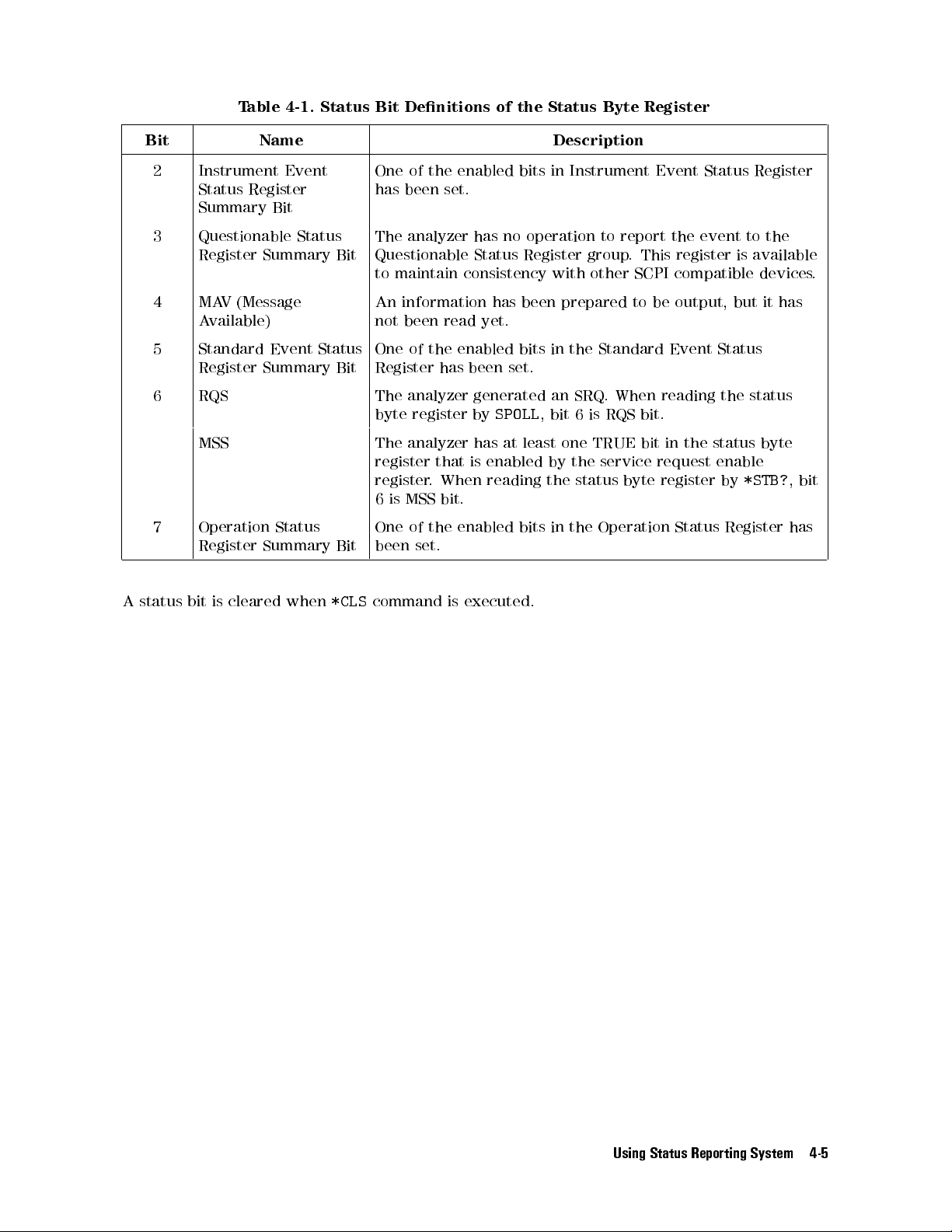
Table 4-1. Status Bit Denitions of the Status Byte Register
Bit Name Description
2 Instrument Event
Status Register
One of the enabled bits in Instrument Event Status Register
has been set.
Summary Bit
3 Questionable Status
Register Summary Bit
The analyzer has no operation to report the event to the
Questionable Status Register group. This register is available
to maintain consistency with other SCPI compatible devices.
4 MAV (Message
Available)
5 Standard Event Status
Register Summary Bit
An information has been prepared to be output, but it has
not been read yet.
One of the enabled bits in the Standard Event Status
Register has been set.
6 RQS The analyzer generated an SRQ. When reading the status
byte register by
SPOLL
, bit 6 is RQS bit.
MSS The analyzer has at least one TRUE bit in the status byte
register that is enabled by the service request enable
register. When reading the status byte register by
6 is MSS bit.
7 Operation Status
Register Summary Bit
A status bit is cleared when
One of the enabled bits in the Operation Status Register has
been set.
*CLS
command is executed.
*STB?
, bit
Using Status Reporting System 4-5
Page 76
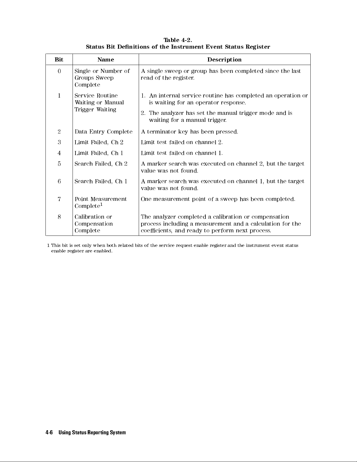
Table 4-2.
Status Bit Denitions of the Instrument Event Status Register
Bit Name Description
0 Single or Number of
Groups Sweep
A single sweep or group has been completed since the last
read of the register.
Complete
1 Service Routine
Waiting or Manual
Trigger Waiting
1. An internal service routine has completed an operation or
is waiting for an operator response.
2. The analyzer has set the manual trigger mode and is
waiting for a manual trigger.
2 Data Entry Complete A terminator key has been pressed.
3 Limit Failed, Ch 2 Limit test failed on channel 2.
4 Limit Failed, Ch 1 Limit test failed on channel 1.
5 Search Failed, Ch 2 A marker search was executed on channel 2, but the target
value was not found.
6 Search Failed, Ch 1 A marker search was executed on channel 1, but the target
value was not found.
7 Point Measurement
Complete
1
8 Calibration or
Compensation
Complete
One measurement point of a sweep has been completed.
The analyzer completed a calibration or compensation
process including a measurement and a calculation for the
coecients, and ready to perform next process.
1
This bit is set only when both related bits of the service request enable register and the instrument event status
enable register are enabled.
4-6 Using Status Reporting System
Page 77

Table 4-3. Status Bit Denitions of the Standard Event Status Register
Bit Name Description
0 Operation Complete The analyzer has completed all pending operations and is
ready to accept new commands. This bit is generated only in
response to the
*OPC
command.
1 Request Control The analyzer requires control of HP-IB to proceed the
current operation.
2 Query Error 1. The analyzer has been addressed to talk, but there is
nothing in the output queue to transmit.
2. Data in the Output Queue has been lost.
3 Device Dependent
Error
An error, other than a command error, a query error,oran
execution error has occurred.
4 Execution Error 1. An HP-IB command parameter exceeded its input range,
or is inconsistent with the analyzer's capabilities.
2. An HP-IB command could not be properly executed due
to some analyzer condition.
5 Command Error 1. An IEEE 488.2 syntax error has occurred. The analyzer
receives a command that did not follow the syntax
dened by the IEEE 488.2 standard. Possible violations
include, a command parameter violated the analyzer
listening formats or a command parameter type is
unacceptable to the analyzer.
2. A semantic error occurred. For example, the analyzer
received an incorrectly spelled command. Another
example would be that the analyzer received an optional
488.2 command that is not implemented to the analyzer
GET
3. The analyzer received a Group Execute Trigger (
)
inside a HP-IB command.
6 User Request The operator pressed a front panel key or an optional
keyboard key or turned the rotary knob.
7 Power ON A power-on sequence has occurred since the register was
last read.
.
Table 4-4. Status Bit Denitions of the Operation Status Register
Bit Name Description
9 Printing Data is being transfered to the printer.
14 Program running An HP Instrument BASIC program is running.
Using Status Reporting System 4-7
Page 78

How to Use the Status Registers in a Program
You can use the status registers to determine the specic analyzer status in the program. To
determine the contents of the status register, the following methods are used:
Read an event register directly.
Use the Service Request (SRQ).
Reading an Event Register Directly
You can read the contents of the event register directly to determine the specic analyzer
condition. Use this method if you do not need to know the timing of the event register
changes. The following procedure reads the register directly:
1. Query the event register contents.
2. Retrieve a return value.
3. Check the bit condition using the BASIC
OUTPUT @Hp4291;"STAT:INST?"
ENTER @Hp4291;Esb
IF BIT(Esb,4) THEN
DISP "LIMIT TEST FAILED AT Ch 1."
BIT
function.
Queries instrument event status register contents.
Retrieve return value.
If bit 4 of the instrument event status register is set to 1, the limit
test failed on channel 1.
END IF
Module 4-1. Reading an Event Register
Related HP-IB Commands. The following query commands can be used to read the contents
of an event register directly.
*STB?
*ESR?
STAT:INST?
STAT:OPER:COND?
Returns Status Byte Register contents.
Returns Event Status Register contents.
Returns Instrument Event Status Register contents.
Returns Operation Status Register contents.
4-8 Using Status Reporting System
Page 79

SRQ and Interrupt
You can initialize your program to enable interrupt processing by the Service Request (SRQ)
from the analyzer. The analyzer generates an SRQ when the specied condition is satised.
The SRQ itself does not contain information on the SRQ source. However, the Request Service
(RQS) bit in the Status Byte Register of the SRQ source device is set to 1. If multiple devices
are connected on the bus, you can check the RQS bit (bit 6) of the analyzer by using a serial
poll,
SPOLL
.
Use the SRQ interrupt if you want to determine when the condition changes. The following
procedure is used to set the SRQ interrupt:
1. Dene the branch for the interruption. (Use
ON INTR
statement.)
2. Set to 1 the enable register for the corespondent event register bit.
3. Set to 1 the service request enable register bit for the correspondent status byte register bit.
4. Clear the status register before enabling the SRQ interruption.
5. Enable the SRQ interruption. (Use
ENABLE INTR
statement.)
6. Start the event.
7. Wait for the SRQ. Usually, the program waits within an endless loop.
8. If multiple devices that can generate an SRQ exist on the HP-IB
the status byte register of the target device
. If the SRQ is generated from the target device
, you should check bit 6 of
the status byte register bit 6 is set to 1.
The following example uses an SRQ interruption for detecting the end of sweep
instrument event status register is used for this purpose
ON INTR Scode GOTO Sweep_end
OUTPUT @Hp4291;"STAT:INST:ENAB 1"
OUTPUT @Hp4291;"*SRE 4"
OUTPUT @Hp4291;"*CLS"
OUTPUT @Hp4291;"*OPC?"
When the SRQ has occurred, jumps to label, \Sweep end."
Set bit 0 of the insturment event status enable register to 1.
Set bit 2 of the service request enable register to 1.
Clears the event register.
Conrms the clear operation is completed.
.
. Bit 0 of the
0
(2
2
(2
=4)
=1)
ENTER @Hp4291;Opc
!
OUTPUT @Hp4291;"TRIG:SOUR INT"
OUTPUT @Hp4291;"INIT:CONT OFF"
OUTPUT @Hp4291;"ABOR"
ENABLE INTR Scode;2
OUTPUT @Hp4291;"INIT"
Waiting: GOTO Waiting
Sweep_end:!
IF NOT BIT(SPOLL(@Hp4291),6) THEN
Selects internal trigger source.
Sets the continuous mode OFF.
Moves trigger sequence to the idle state.
Enables the SRQ interruption just before triggering.
Trigger a measurement.
Waits until SRQ is generated.
When on SRQ, program jumps to this label.
Check the SRQ is generated from the target device by checking status
byte register bit 6.
ENABLE INTR Scode;2
GOTO Waiting
If not, enable the SRQ again, then
returns to the endless looping.
END IF
,
Note
Module 4-2. Detecting Sweep End Using SRQ and Interrupt
*CLS
clears only the event registers and the status byte register. The enable
register and transition lter settings are not altered by executing the
, use
command. To clear the enable register and transition lter
SYST:PRES
command.
Using Status Reporting System 4-9
*CLS
Page 80
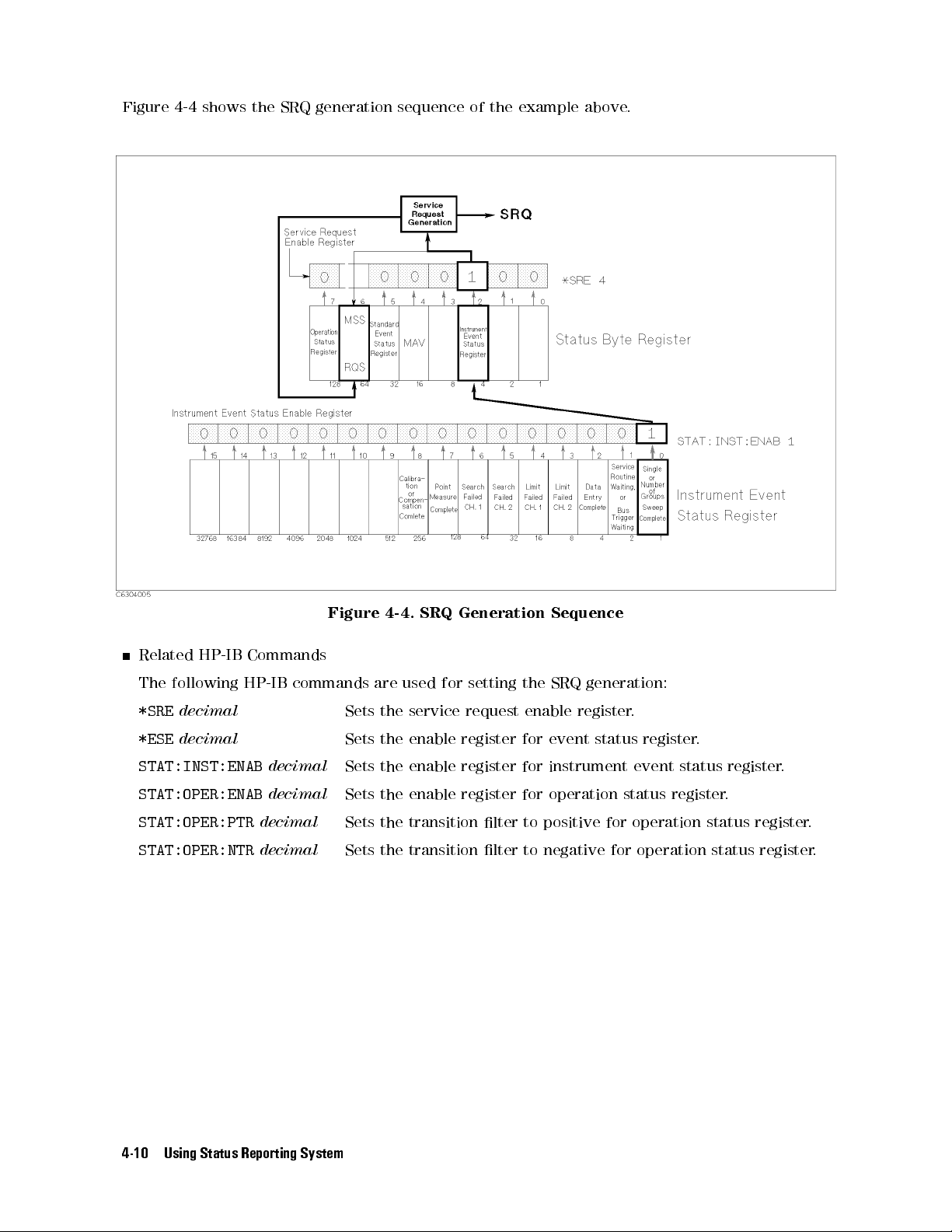
Figure 4-4 shows the SRQ generation sequence of the example above.
Figure 4-4. SRQ Generation Sequence
Related HP-IB Commands
The following HP-IB commands are used for setting the SRQ generation:
*SRE
decimal
*ESE
decimal
STAT:INST:ENAB
STAT:OPER:ENAB
STAT:OPER:PTR
STAT:OPER:NTR
decimal
decimal
decimal
decimal
Sets the service request enable register.
Sets the enable register for event status register.
Sets the enable register for instrument event status register.
Sets the enable register for operation status register.
Sets the transition lter to positive for operation status register.
Sets the transition lter to negative for operation status register
.
4-10 Using Status Reporting System
Page 81

Sample Program: Performing Calibration
This sample program automates the calibration process.For the same reason as the xture
compensation process that is discussed in Chapter 2, the calibration process also requires
synchronizing the program with the analyzer by detecting the calibration process completion.
The calibration process measures a standard in three dierent settings. Bit 8 of the instrument
event status register (\Calibration or Compensation Complete" bit) is set to 1 when all
measurements are completed. By setting the enable registers to generate an SRQ from this bit,
you can detect the end of the calibration process of each standard.
You have to use an SRQ interrupt for measuring every standard. When you enable the
interrupt, do not forget to clear the register to avoid an unexpected interruption from
occurring. Clearing register by
*CLS
does not alter the enable register setting. Therefore,
setting the enable register only occurs once in this program (lines 330 and 340).
This program is included in the sample program disk. Its lename is
CAL
. This
program is initialized for Instrument BASIC. The program for the external
controller,
CAL_E
, is also included in the
Sample Program Disk
.
100 !**** INITIALIZE ****
110 ASSIGN @Hp4291 TO 800
120 Scode=8
130 CLEAR @Hp4291
140 ABORT Scode
150 !
160 !**** CALIBRATION STATE CHEKING ****
170 OUTPUT @Hp4291;"SENS:CORR1?"
180 ENTER @Hp4291;Stat
190 IF Stat THEN
200 INPUT "ARE YOU SURE TO RE-CALIBRATE NOW? [Y/N]",Ans$
210 IF Ans$"Y" THEN STOP
220 END IF
230 !
240 !**** SELECTING CAL MODE (USRER/FIXED) ****
250 INPUT "SELECT CAL MODE [F]IXED OR [U]SER. [F/U] (DEFAULT=F)",Cal_mode$
260 IF Cal_mode$="U" THEN
270 OUTPUT @Hp4291;"SENS:CORR1:COLL:FPO USER"
280 ELSE
290 OUTPUT @Hp4291;"SENS:CORR1:COLL:FPO FIX"
300 END IF
310 !
320 !**** SETTING ENABLE REGISTER FOR SRQ ****
330 OUTPUT @Hp4291;"STAT:INST:ENAB 256"
340 OUTPUT @Hp4291;"*SRE 4"
350 OUTPUT @Hp4291;"TRIG:SOUR INT"
360 !
370 !**** OPEN STD. MEASUREMENT ****
380 ON INTR Scode GOTO Open_end
390 OUTPUT @Hp4291;"*CLS;*OPC?"
400 ENTER @Hp4291;Opc
410 INPUT "CONNECT OPEN, THEN PRESS [RETURN]",A
420 ENABLE INTR Scode;2
Using Status Reporting System 4-11
Page 82

430 OUTPUT @Hp4291;"SENS:CORR1:COLL STAN1"
440 Wait_open:GOTO Wait_open
450 Open_end:!
460 !
470 !**** SHORT STD. MEASUREMENT ****
480 ON INTR Scode GOTO Short_end
490 OUTPUT @Hp4291;"*CLS;*OPC?"
500 ENTER @Hp4291;Opc
510 INPUT "CONNECT SHORT, THEN PRESS [RETURN]",A
520 ENABLE INTR Scode;2
530 OUTPUT @Hp4291;"SENS:CORR1:COLL STAN2"
540 Wait_short:GOTO Wait_short
550 Short_end:!
560 !
570 !**** LOAD STD. MEASUREMENT ****
580 ON INTR Scode GOTO Load_end
590 OUTPUT @Hp4291;"*CLS;*OPC?"
600 ENTER @Hp4291;Opc
610 INPUT "CONNECT LOAD, THEN PRESS [RETURN]",A
620 ENABLE INTR Scode;2
630 OUTPUT @Hp4291;"SENS:CORR1:COLL STAN3"
640 Wait_load:GOTO Wait_load
650 Load_end:!
660 !
670 !**** LOW-LOSS C MEASUREMENT ****
680 INPUT "DO YOU WANT TO MESURE LOW-LOSS C? [Y/N] Default=Y",A$
690 IF A$="N" OR A$="n" THEN Skip
700 ON INTR Scode GOTO Llc_end
710 OUTPUT @Hp4291;"*CLS;*OPC?"
720 ENTER @Hp4291;Opc
730 INPUT "CONNECT LOW-LOSS C, THEN PRESS [RETURN]",A
740 ENABLE INTR Scode;2
750 OUTPUT @Hp4291;"SENS:CORR1:COLL STAN4"
760 Wait_llc:GOTO Wait_llc
770 Llc_end:!
780 !
790 Skip:!
800 OUTPUT @Hp4291;"SENS:CORR1:COLL:SAVE"
810 !
820 END
4-12 Using Status Reporting System
Page 83

Using the Trigger System
This chapter provides information about the SCPI trigger system of the analyzer. SCPI denes
a common trigger system for various types of instruments. This means you can control the
analyzer for your measurements using operations that are common to other instruments.
The analyzer has two trigger modes: trigger on sweep mode and trigger on point mode. The
trigger on sweep mode sweeps all measurement points with single trigger input. The trigger
on point mode requires a trigger for every measurement point. This section describes the
characteristics and dierences of each mode.
5
Using the Trigger System 5-1
Page 84

Trigger System
The trigger system has three states during a measurement. Figure 5-1 shows the trigger
sequence:
Figure 5-1. Simplied Trigger System
Idle State
The idle state is the start point of the trigger sequence
. The idle state has the following
characteristics:
*RSTorABORt
INIT(:IMM)
If
INIT:CONT ON
sets the analyzer to the idle state at anytime during the sequence
moves the trigger sequence to the wait for trigger state from the idle state
is set, the trigger sequence immediately moves to the wait for trigger state
When the analyzer in the idle state, the
Hld
notation is displayed on the left edge of the
.
.
display.
Wait for Trigger State
In the wait for trigger state, the analyzer waits for a selected trigger event. It then moves to
the measurement state.
The following trigger sources are available for the analyzer:
Trigger
Trigger Event
Source
INTERNAL
Internal trigger source. This source continuously generates a trigger event.
The trigger sequence immediately moves to the measurement state.
.
EXTERNAL
External trigger source. Apply a TTL level pulse longer than 2s to the
external trigger connector on the rear panel to trigger
NEG
toggles the polarity of the trigger signal to positive or negative logic
respectively.
MANUAL
Manual trigger. Press
5-2 Using the Trigger System
NNNNNNNNNNNNNNNNNNNN
MANUAL
key under
4
Trigger
.
TRIG:SLOP POS
NNNNNNNNNNNNNNNNNNNNNNNNNNNNNNNNNNNNNNNNNNNNNNNNNN
5
TRIGGER [MANUAL]
or
,
to trigger.
Page 85

BUS
Measurement State
In this state, the analyzer makes a measurement. The measurement method depends on
whether the selected measurement mode is the trigger on sweep mode or the trigger on point
mode.
When the trigger on sweep mode is selected, the analyzer measures all points by a single
trigger. After all the point measurements are completed, it exits the measurement state to the
idle state. If the number of groups sweep is selected, it goes back to the wait for trigger state
and repeats this loop until the specied number of groups is completed. It then moves to the
idle state. If the single sweep is selected, the trigger sequence immediately moves to the idle
state after all point measurements are completed.
If
INIT:CONT ON
trigger state.
When the trigger on point mode is selected, the analyzer measures one point and then moves
to the wait for trigger state. Therefore, you must apply a trigger for each point measurement.
When the measurement point reaches the right edge of the display
the same as the trigger on sweep mode.
If
INIT:CONT ON
after exiting from the measurement state.
HP-IB trigger. Executing either of the following statements triggers a
measurement.
OUTPUT @Hp4291;"*TRG"orTRIGGER @Hp4291
is selected, the trigger sequence skips the idle state and goes to the wait for
, the trigger sequence acts
is set, the trigger sequence immediately moves to the wait for trigger state
Using the Trigger System 5-3
Page 86
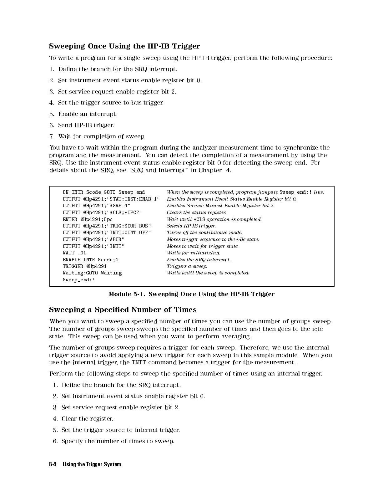
Sweeping Once Using the HP-IB Trigger
To write a program for a single sweep using the HP-IB trigger, perform the following procedure:
1. Dene the branch for the SRQ interrupt.
2. Set instrument event status enable register bit 0.
3. Set service request enable register bit 2.
4. Set the trigger source to bus trigger.
5. Enable an interrupt.
6. Send HP-IB trigger.
7. Wait for completion of sweep.
You have to wait within the program during the analyzer measurement time to synchronize the
program and the measurement. You can detect the completion of a measurement by using the
SRQ. Use the instrument event status enable register bit 0 for detecting the sweep end. For
details about the SRQ, see \SRQ and Interrupt" in Chapter 4.
ON INTR Scode GOTO Sweep_end
OUTPUT @Hp4291;"STAT:INST:ENAB 1"
OUTPUT @Hp4291;"*SRE 4"
OUTPUT @Hp4291;"*CLS;*OPC?"
ENTER @Hp4291;Opc
OUTPUT @Hp4291;"TRIG:SOUR BUS"
OUTPUT @Hp4291;"INIT:CONT OFF"
OUTPUT @Hp4291;"ABOR"
OUTPUT @Hp4291;"INIT"
WAIT .01
ENABLE INTR Scode;2
TRIGGER @Hp4291
Waiting:GOTO Waiting
When the sweep is completed, program jumps to
Sweep_end:!
Enables Instrument Event Status Enable Register bit 0.
Enables Service Request Enable Register bit 2.
Clears the status register.
Wait until
*CLS
operation is completed.
Selects HP-IB trigger.
Turns o the continuouse mode.
Moves trigger sequence to the idle state.
Moves to wait for trigger state.
Waits for initializing.
Enables the SRQ interrupt.
Triggers a sweep.
Waits until the sweep is completed.
line.
Sweep_end:!
Module 5-1. Sweeping Once Using the HP-IB Trigger
Sweeping a Specied Number of Times
When you want to sweep a specied number of times you can use the number of groups sweep.
The number of groups sweep sweeps the specied number of times and then goes to the idle
state. This sweep can be used when you want to perform averaging.
The number of groups sweep requires a trigger for each sweep
trigger source to avoid applying a new trigger for each sweep in this sample module
use the internal trigger, the
INIT
command becomes a trigger for the measurement.
. Therefore, we use the internal
. When you
Perform the following steps to sweep the specied number of times using an internal trigger.
1. Dene the branch for the SRQ interrupt.
2. Set instrument event status enable register bit 0.
3. Set service request enable register bit 2.
4. Clear the register.
5. Set the trigger source to internal trigger.
6. Specify the number of times to sweep
.
5-4 Using the Trigger System
Page 87

7. Set
INIT:CONT OFF
.
8. Move the trigger sequence to the Idle state using the
ABOR
command.
9. Enable an interrupt.
10. Start number of groups sweep by sending
INIT
command.
11. Wait for completion of specied number of sweeps.
When the number of groups sweep is selected, the instrument event status register bit 0 also
indicates the status of the number of groups sweep. When the specied number of sweeps are
completed, this bit is set to 1.
ON INTR Scode GOTO Sweep_end
OUTPUT @Hp4291;"STAT:INST:ENAB 1"
OUTPUT @Hp4291;"*SRE 4"
OUTPUT @Hp4291;"*CLS;*OPC?"
ENTER @Hp4291;Opc
OUTPUT @Hp4291;"TRIG:SOUR INT"
OUTPUT @Hp4291;"INIT:CONT OFF"
OUTPUT @Hp4291;"SENS:SWE:COUN 16"
OUTPUT @Hp4291;"ABOR"
ENABLE INTR Scode;2
OUTPUT @Hp4291;"INIT"
Waiting:GOTO Waiting
When the sweep is completed, program jumps to
Sweep_end:!
Enables Instrument Event Status Enable Register bit 0.
Enables Service Request Enable Register bit 2.
Clears the status register.
Wait until
*CLS
operation is completed.
Selects internal trigger.You can omit this line after presetting .
Turns the continuous mode o.
Sets the number of sweeps to 16.
Moves to the idle state.
Enables the SRQ interrupt.
Start a measurement.
Waits until the sweep is completed.
line.
Sweep_end:!
Module 5-2. Sweeping a Specied Number of Times
Related HP-IB Commands
The following commands set the averaging requirements:
SENS:AVER2:COUN
value
;STAT ON
Specify the averaging factor and turns averaging ON.
Triggering on Each Point Using the Manual Trigger
The following program module makes a point measurement using the manual trigger and
displays the measured value on the display:
1. Set instrument event status enable register bit 7.
2. Set service request enable register bit 2.
3. Set the trigger source to manual.
4. Select trigger on point mode.
5. Move to wait for trigger state.
6. Enable an interrupt.
7.
Press
NNNNNNNNNNNNNNNNNNNN
MANUAL
under
4
Trigger
NNNNNNNNNNNNNNNNNNNNNNNNNNNNNNNNNNNNNNNNNNNNNNNNNNNNNNNN
5
TRIGGER:[FREE RUN]
.
8. Wait for completion of point measurement.
9. Query the measured point value.
10. Display the value.
11. Repeat 6 to 10.
Using the Trigger System 5-5
Page 88

Use the \Point Measure Complete" bit (Instrument event status enable register bit 7) to detect
the end of the on point measurement.
OUTPUT @Hp4291;"TRIG:SOUR MAN"
OUTPUT @Hp4291;"TRIG:EVEN:TYPE POIN"
Selects manual trigger.
Select trigger on point mode.
ON INTR Scode GOTO Sweep_end
OUTPUT @Hp4291;"STAT:INST:ENAB 128;*SRE 4"
OUTPUT @Hp4291;"INIT"
Set SRQ generation with point measure complete.
Move to wait for trigger state.
FOR I=1 TO 201
OUTPUT @Hp4291;"*CLS;*OPC?"
ENTER @Hp4291;Opc
ENABLE INTR Scode;2
Waiting:GOTO Waiting
Enable the SRQ interrupt.
Wait for trigger and measurement completion.
Sweep_end:!
OUTPUT @Hp4291;"TRAC:VAL? DTR,";I
ENTER @Hp4291;Value
PRINT Value
Output a measured point value.
Receive a response.
Display received value.
NEXT I
Module 5-3. Triggering on Each Point Using the Manual Trigger
Related HP-IB Commands
The following commands selects the trigger mode:
TRIG:EVEN:TYPE SWE
TRIG:EVEN:TYPE POIN
Selects trigger on sweep mode.
Selects trigger on point mode.
The following commands output a specied measurement point value:
TRAC:VAL? DTR,
point
Outputs the specied point data of the data trace of the active
channel.
TRAC:VAL? MTR,
point
Outputs the specied point data of the memory trace of the
active channel.
TRAC:VAL? DTRCH1,
TRAC:VAL? DTRCH2,
point
point
Outputs the specied point data of the data trace of channel 1.
Outputs the specied point data of the data trace of channel 2.
The following commands sets the averaging on point:
SENS:AVER1:COUN
SENS:SWE:DWEL1
value
;STAT ON
value
;DWEL1:AUTO ON
Sets the point averaging factor and turns on it.
Sets the point delay time.
5-6 Using the Trigger System
Page 89

Using the I/O Port
The analyzer has an 8-bit general purpose input/output port on the rear panel. You can use
this port to connect an external instrument to the analyzer. This chapter describes the pin
assignment, access commands and a sample program for using with a handler.
This chapter contains:
I/O port pin assignment
Accessing I/O port
Sample program: BIN sorting using the I/O port
I/O Port Pin Assignment
Figure 6-1 shows the hardware pin assignment of the I/O port.
6
Figure 6-1. I/O Port Pin Assignment
There are 4 pins for input and 8 pins for output. Therefore
for input and 8 bit data for output.
, the analyzer can handle 4 bit data
Using the I/O Port 6-1
Page 90

Accessing I/O Port
To read or write to the I/O port from Instrument BASIC, use the following command:
Dat=11
WRITEIO 15,0;Dat
Outputs \11". (bit 0,1, and 3 are ON)
Module 6-1. Send Data to I/O Port
You may notice that Module 6-1 does not use an
Instead it uses the
WRITEIO
statement. The
OUTPUT
WRITEIO
statement to access to the I/O port.
statement of Instrument BASIC is
provided for the purpose of accessing the I/O port. This statement allows faster access than the
OUTPUT
statement because it directly accesses the I/O port. Therefore, this statement can only
be used with Instrument BASIC.
Dat=READIO(15,0)
Returns 4 bit decimal value from input of I/O port.
Module 6-2. Reading Data from I/O Port
Like the
with Instrument BASIC.
WRITEIO
statement,
READIO
READIO
allows you to read data from the input of the I/O port
is a function that you can use in equations
.
Access I/O Port from the External Controller
If you want to access the I/O port from an external controller
command with the
OUTPUT
statement instead of using the
To write data to the I/O port from the external controller
, you have to use an HP-IB
READIOorWRITEIO
commands.
, use the following HP-IB command:
OUTPUT @Hp4291;"SYST:COMM:PAR:TRAN:DATA ";Dat
Module 6-3. Send Data to I/O Port from an External Controller
To read data from the I/O port to the external controller, use the following HP-IB commands:
OUTPUT @Hp4291;"SYST:COMM:PAR:DATA?"
ENTER @Hp4291;Dat
Module 6-4. Reading Data from I/O Port to an External Controller
Note
When you are using a fast external controller to control the analyzer,a
continuously looping query causes the analyzer to lock up. If this happens, add
a
WAIT
statement within the loop to slow down the query frequency.
6-2 Using the I/O Port
Page 91

Sample Program: BIN Sorting Using the I/O Port
This section provides a sample program that performs BIN sorting with the external handler
and outputs the result via the I/O port.
This sample program sorts the DUTs into 4 bins using the dierence rate from a reference value
at a xed frequency. Then it outputs the result of sorting to the I/O port.
Connect the analyzer and the external handler as shown in Figure 6-2.
Figure 6-2. Connecting I/O Port
Each output pin is set to TRUE if it satises the following conditions:
OUT 0 Measured C is in the range of 5 % to the reference.
OUT 1 Measured C is in the range of 10 % to the reference.
OUT 2 Measured C is 10 % greater than the reference.
OUT 3 Measured C is 10 % less than the reference
OUT 4 to 5 Not assigned
OUT 6 Analyzer nished measurement and BIN sorting.
OUT 7 Analyzer ready to accept a trigger.
The external handler can monitor OUT 6 and 7. When OUT 6 is set to TRUE, the handler reads
the BIN result and sorts out the DUT. Then, it sets the next DUT to the measurement stage.
The external handler can apply the trigger signal when OUT 7 is set to TRUE.
.
Using the I/O Port 6-3
Page 92

Figure 6-3. Timing Chart
Figure 6-3 shows the timing chart for this program. Note that the I/O port is negative logic
,
therefore, TRUE is low and FALSE is high. This can be change by setting.
The ow of this program is as follows:
1. Set up the measurement.
2. Prepare the SRQ interrupt for a sweep end detection.
3. Wait for a trigger input. Sets OUT 7 to TRUE.
4. When the trigger is applied, start measuring the DUT
. Set all pins to FALSE.
5. Sort the measured result.
6. Output the result of the BIN sorting and set OUT 6 to TRUE.
7. Return to 2.
This program pauses when in the wait for trigger state. Apply the RUN/CONT signal instead of
the external trigger.
This program is included in the sample program disk. Its lename is
This program is initialized for the Instrument B
the external controller in the
Sample Program Disk
ASIC. There is no program for
.
BINSORT
100 !**** INITIALIZE ****
110 ASSIGN @Hp4291 TO 800
120 Scode=8
130 ABORT Scode
140 CLEAR @Hp4291
150 OUTPUT @Hp4291;"DISP:ALL HIHB"
160 !
170 !*** CONSTANTS ****
180 Crefl=2.E-12 ! C Reference = 10pF
.
6-4 Using the I/O Port
Page 93

190 Count=1
200 Nop=801 ! NUMBER OF POINTS
210 Cent=1.E+8 ! CENTER 100 MHz
220 Span=0 ! SPAN 0 Hz (Zero Span)
230 !
240 !*** BIN COUNTER INITIAL VALUE ****
250 Bin=0
260 Bin1=0! C:+-5%
270 Bin2=0! C:+-10%
280 Bin3=0! C:>+10%
290 Bin4=0! C:<-10%
300 !
310 !*** MEASUREMENT SETUP ****
320 OUTPUT @Hp4291;"SENS:FREQ:CENT ";Cent
330 OUTPUT @Hp4291;"SENS:FREQ:SPAN ";Span
340 OUTPUT @Hp4291;"SENS:SWE:POIN ";Nop
350 OUTPUT @Hp4291;"CALC:FORM CP"
360 !
370 !*** TRIGGER SETUP ****
380 OUTPUT @Hp4291;"TRIG:SOUR BUS"
390 OUTPUT @Hp4291;"TRIG:EVEN:TYPE POIN"
400 OUTPUT @Hp4291;"INIT:CONT ON"
410 !
420 !*** SRQ SETUP FOR TRIGGER ON POINT ****
430 ON INTR Scode GOTO Swp_end
440 OUTPUT @Hp4291;"STAT:INST:ENAB 128"
450 OUTPUT @Hp4291;"*SRE 4"
460 !
470 !*** MEASUREMENT START ****
480 DISP ""
490 Start:!
500 !
510 !****** COUNTER ******
520 Point=Count MOD Nop
530 IF Point=0 THEN Point=Nop
540 !
550 !****** TRIGGER ******
560 OUTPUT @Hp4291;"*CLS;*OPC?"
570 ENTER @Hp4291;Opc
580 WRITEIO 15,0;BINIOR(Bin,2^7)
590 PAUSE
600 ENABLE INTR Scode;2
610 WRITEIO 15,0;0
620 TRIGGER @Hp4291
630 Wait_swp:GOTO Wait_swp
640 Swp_end:!
650 !
660 !*** GET MEASURED C DATA ***
670 Data_out_q:!
680 OUTPUT @Hp4291;"TRAC:VAL? DTR,";Point
690 ENTER @Hp4291;Cmeas
700 C10=Crefl*.1
710 C5=Crefl*.05
720 Cdelta=Cmeas-Crefl
730 IF ABS(Cdelta)>C10 THEN
Using the I/O Port 6-5
Page 94

740 IF SGN(Cdelta) THEN
750 Bin=2^2
760 Bin3=Bin3+1
770 ELSE
780 Bin=2^3
790 Bin4=Bin4+1
800 END IF
810 ELSE
820 IF ABS(Cdelta)<=C5 THEN
830 Bin=2^0
840 Bin1=Bin1+1
850 GOTO Eom
860 ELSE
870 IF ABS(Cdelta)<=C10 THEN
880 Bin=2^1
890 Bin2=Bin2+1
900 GOTO Eom
910 END IF
920 END IF
930 END IF
940 !
950 Eom:!
960 PRINT TABXY(1,1),"COUNT:";Count
970 PRINT TABXY(1,2),"BIN:";Bin
980 Count=Count+1
990 WRITEIO 15,0;BINIOR(Bin,2^6)
1000 GOTO Start
1010 !
1020 Done:!
1030 END
6-6 Using the I/O Port
Page 95

Using the User Traces
The analyzer has a user denable trace feature. If you want to display data using custom
formats or parameters that are not provided in the analyzer, you can display any x-axis or
y-axis format that you specify. This chapter describes user traces and how to use them.
This chapter contains:
What's the user trace?
Using a user trace
Sample program: time characteristic measurement
What's the User Trace?
The user trace function of the analyzer has the following features:
You can display up to 4 arbitrary traces.
You can independently dene x-axis and y-axis units, labels, and scales for each trace.
7
Marker functions can be used on the user traces
For example, when you want to display the time characteristics of an impedance
dene the x-axis as time and the y-axis as impedance
This feature allows you to obtain the trace you want last on the display
You cannot display the user trace and the normal measurement display simultaneously
you are displaying the user trace, the measurement screen disappears, but the measurement
function is still active. Therefore, you can make a measurement in the background while
displaying a user trace.
.
, you can rst
. Then display the trace in that format.
.
. When
Using the User Traces 7-1
Page 96

Using a User Trace
Figure 7-1 shows the user trace parameters that you can specify and the related HP-IB
commands for user trace 1.
Figure 7-1. User Trace
You can dene four user traces as described previously
. Each trace can have dierent settings
for the unit, footnote, headline, and scale. The HP-IB commands for user trace 1 are listed in
Figure 7-1. Table 7-1 lists the corresponding commands for user traces 2 t o 4.
Table 7-1. HP-IB Commands for User Trace 1 to 4
User Trace Unit & Scale NOP X-axis Data Y-axis Data Headline Footnote
1
2
3
4
DISP:TRAC18
DISP:TRAC19
DISP:TRAC20
DISP:TRAC21
...
TRAC:POIN TR18 TRAC TRX18 TRAC TRY18 DISP:TEXT31 DISP:TEXT35
...
TRAC:POIN TR19 TRAC TRX19 TRAC TRY19 DISP:TEXT32 DISP:TEXT36
...
TRAC:POIN TR20 TRAC TRX20 TRAC TRY20 DISP:TEXT33 DISP:TEXT37
...
TRAC:POIN TR21 TRAC TRX21 TRAC TRY21 DISP:TEXT34 DISP:TEXT38
To display a user trace, perform the following procedure:
1. Set a grid for x-axis and y-axis.
2. Set data for the user trace.
3. Turn the user trace on.
4. When the operation is completed, delete the user trace
.
7-2 Using the User Traces
Page 97

Setting A Grid
First dene the grid specications for the data of the user trace. The specications for the grid
are divided into x-axis and y-axis.
For the x-axis, set the unit, the left edge value (start), the right edge value (stop), and the
footnote.
OUTPUT @Hp4291;"DISP:TRAC18:X:UNIT 'SEC'"
OUTPUT @Hp4291;"DISP:TRAC18:X:LEFT 0"
OUTPUT @Hp4291;"DISP:TRAC18:X:RIGH 100"
OUTPUT @Hp4291;"DISP:TEXT35 'ELAPSE TIME'"
Dene X-axis unit.
Dene min. edge of the x-axis of user trace.
Dene max. edge of the x-axis of user trace.
Put a footnote.
Module 7-1. Setting Grid For X-Axis
For the y-axis, set the unit, the top and bottom values for the scale, and the headline.
OUTPUT @Hp4291;"DISP:TRAC18:Y:UNIT 'F'"
OUTPUT @Hp4291;"DISP:TRAC18:Y:BOTT 10E-12"
OUTPUT @Hp4291;"DISP:TRAC18:X:TOP 200E-12"
OUTPUT @Hp4291;"DISP:TEXT31 'Cp'"
Dene Y-axis unit.
Dene min. edge of the y-axis of user trace to 10 pF.
Dene max. edge of the y-axis of user trace to 200 pF
Put a headline.
Module 7-2. Setting Grid For Y-Axis
Related HP-IB Commands
You can toggle the linear or log scale for the x and y-axis:
DISP:TRAC{18-21}:Y:SPAC LIN
DISP:TRAC{18-21}:Y:SPAC LOG
DISP:TRAC{18-21}:X:SPAC LIN
DISP:TRAC{18-21}:X:SPAC LOG
The default grid setting of the four user traces is common. T
Set y-axis to the linear scale. (Default)
Set y-axis to the log scale.
Set x-axis to the linear scale. (Default)
Set x-axis to the log scale.
o dene each trace's unit,
headline, footnote, and scale individually, turn o the grid coupling by using the following
command:
.
DISP:TRAC{18-21}:GRAT:AXIS:COUP OFF
Turning o the scale and grid coupling.
Setting Data Train for The Trace
After you dene a grid specication, enter the x-axis and the y-axis data into the user trace's
data arrays. This enables the analyzer to display the user trace
.
You must ensure that the number of points and number of x-axis and y-axis data are equal.
Otherwise, if it is greater or less than equal, an HP-IB error occurs.
OUTPUT @Hp4291;"TRAC:POIN TR18,201"
OUTPUT @Hp4291;"TRAC TRY18,";Y_data(*)
OUTPUT @Hp4291;"TRAC TRX18,";X_data(*)
Denes Number of points.
Sets Y-Axis Values.
Sets X-Axis Values.
Module 7-3. Setting Data Train for X- and Y-axis
You can change scale specications after setting x-axis and y-axis trace data. The following
module sets the optimized scale setting for the user trace
.
Using the User Traces 7-3
Page 98

OUTPUT @Hp4291;"DISP:TRAC18:Y:AUTO ONCE"
Adjust the scale to t the trace in the grid.
TRAC18
is for
the user trace 1.
Module 7-4. Automatic Scaling for User Trace
Related HP-IB Commands
You can copy the data or memory trace data of the measurement display to the user trace
array. At this time, the number of points is reset to the same setting as the measurement
display.
TRAC:COPY TR{18-21},TR1
Copies data trace data, number of points, stimulus, and
units for x and y-axis of the active channel to user trace 1
to 4, respectively.
TRAC:COPY TR{18-21},TR2
Copies selected memory trace data, number of points,
stimulus, and units for x and y-axis of the active channel to
user trace 1 to 4.
Turning ON the User Trace
When you nish setting the user trace parameters, turn it on to display the user trace
OUTPUT @Hp4291;"DISP:TRAC18:STAT ON"
Turn on the user trace.
Module 7-5. Turning ON the User Trace
Using the Marker on a User Trace
You can use the marker on a user trace just as it is used on the data trace
. The following
module puts the marker on the user trace 1.
OUTPUT @Hp4291;"CALC:EVAL:ON 'TR18'"
Sets the marker to work on the user trace 1.
Module 7-6. Using Marker on the User Trace
.
Clearing a User Trace
When you nish using a user trace, you should release the allocated memory for the use of
other functions. When you clear the user trace, the user trace display is automatically turned
o.
OUTPUT @Hp4291;"DISP:TRAC18:CLE"
Clear all user trace data and turn o the user trace display.
Module 7-7. Turning OFF and Clearing The User Trace
7-4 Using the User Traces
Page 99
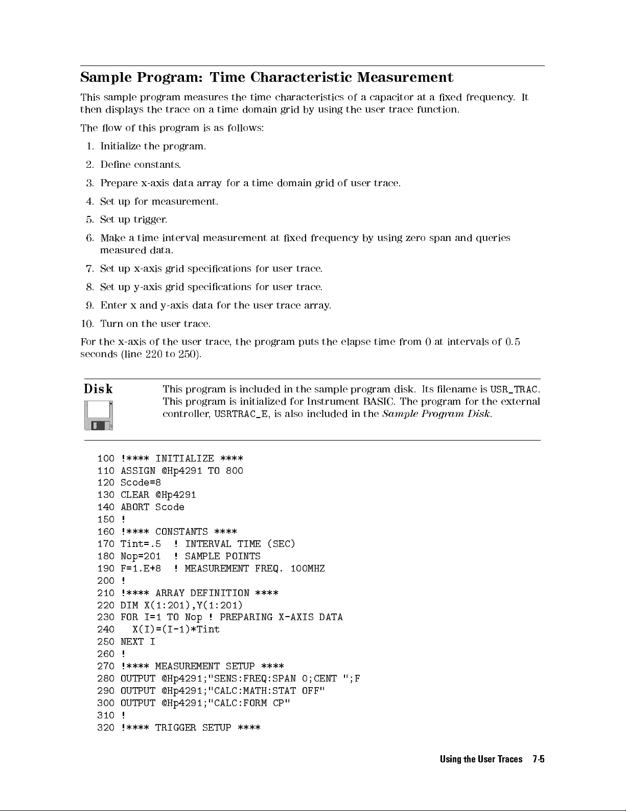
Sample Program: Time Characteristic Measurement
This sample program measures the time characteristics of a capacitor at a xed frequency.It
then displays the trace on a time domain grid by using the user trace function.
The ow of this program is as follows:
1. Initialize the program.
2. Dene constants.
3. Prepare x-axis data array for a time domain grid of user trace.
4. Set up for measurement.
5. Set up trigger.
6. Make a time interval measurement at xed frequency by using zero span and queries
measured data.
7. Set up x-axis grid specications for user trace.
8. Set up y-axis grid specications for user trace.
9. Enter x and y-axis data for the user trace array
.
10. Turn on the user trace.
For the x-axis of the user trace, the program puts the elapse time from 0 at intervals of 0.5
seconds (line 220 to 250).
This program is included in the sample program disk. Its lename is
USR_TRAC
This program is initialized for Instrument BASIC. The program for the external
controller,
USRTRAC_E
, is also included in the
Sample Program Disk
.
100 !**** INITIALIZE ****
110 ASSIGN @Hp4291 TO 800
120 Scode=8
130 CLEAR @Hp4291
140 ABORT Scode
150 !
160 !**** CONSTANTS ****
170 Tint=.5 ! INTERVAL TIME (SEC)
180 Nop=201 ! SAMPLE POINTS
190 F=1.E+8 ! MEASUREMENT FREQ. 100MHZ
200 !
210 !**** ARRAY DEFINITION ****
220 DIM X(1:201),Y(1:201)
230 FOR I=1 TO Nop ! PREPARING X-AXIS DATA
240 X(I)=(I-1)*Tint
250 NEXT I
260 !
270 !**** MEASUREMENT SETUP ****
280 OUTPUT @Hp4291;"SENS:FREQ:SPAN 0;CENT ";F
290 OUTPUT @Hp4291;"CALC:MATH:STAT OFF"
300 OUTPUT @Hp4291;"CALC:FORM CP"
310 !
320 !**** TRIGGER SETUP ****
.
Using the User Traces 7-5
Page 100

330 OUTPUT @Hp4291;"STAT:INST:ENAB 128"
340 OUTPUT @Hp4291;"*SRE 4"
350 ON INTR Scode GOTO Sweep_end
360 OUTPUT @Hp4291;"TRIG:SOUR BUS"
370 OUTPUT @Hp4291;"INIT:CONT ON;"
380 OUTPUT @Hp4291;"TRIG:EVEN:TYPE POIN"
390 !
400 !**** TIME-INTERVAL MEASUREMENT ****
410 T1=TIMEDATE
420 FOR I=1 TO Nop
430 OUTPUT @Hp4291;"*CLS;*OPC?"
440 ENTER @Hp4291;Opc
450 ENABLE INTR Scode;2
460 TRIGGER @Hp4291
470 Waiting:GOTO Waiting
480 Sweep_end:!
490 OUTPUT @Hp4291;"TRAC:VAL? DTR,";I
500 ENTER @Hp4291;Y(I)
510 DISP (I-1)*Tint;TAB(7);"[SEC]"
520 REPEAT ! CHECKING INTERVAL TIME.
530 T2=TIMEDATE ! IF INTERVAL EXCEEDS
540 UNTIL T2>T1+Tint ! LOOP WILL EXIT.
550 T1=T2
560 NEXT I
570 !
580 !**** SETTING GRID FOR X-AXIS ****
590 OUTPUT @Hp4291;"DISP:TRAC18:X:UNIT 'SEC'"
600 OUTPUT @Hp4291;"DISP:TRAC18:X:LEFT ";X(1)
610 OUTPUT @Hp4291;"DISP:TRAC18:X:RIGHT ";X(Nop)
620 OUTPUT @Hp4291;"DISP:TEXT35 'ELAPSE TIME'"
630 !
640 !**** SETTING GRID FOR Y-AXIS ****
650 OUTPUT @Hp4291;"DISP:TRAC18:Y:UNIT 'F'"
660 OUTPUT @Hp4291;"DISP:TRAC18:Y:BOTT ";MIN(Y(*))
670 OUTPUT @Hp4291;"DISP:TRAC18:Y:TOP ";MAX(Y(*))
680 OUTPUT @Hp4291;"DISP:TEXT31 'Cp'"
690 !
700 !**** SETTING X AND Y-AXIS DATA ****
710 OUTPUT @Hp4291;"TRAC:POIN TR18,";Nop
720 OUTPUT @Hp4291;"TRAC TRX18,";X(*)
730 OUTPUT @Hp4291;"TRAC TRY18,";Y(*)
740 !
750 !**** TURNING ON USER TRACE ****
760 OUTPUT @Hp4291;"DISP:TRAC18:STAT ON"
770 !
780 !**** TURNING ON MARKER ****
790 OUTPUT @Hp4291;"CALC:EVAL:ON 'TR18'"
800 OUTPUT @Hp4291;"CALC:EVAL:INT OFF"
810 !
820 !**** CLEARING USER TRACE ****
830 INPUT "MOVE MARKER, OR PRESS [RETURN] TO CLEAR TRACE",Ans$
840 OUTPUT @Hp4291;"DISP:TRAC18:CLE"
850 !
860 END
7-6 Using the User Traces
 Loading...