

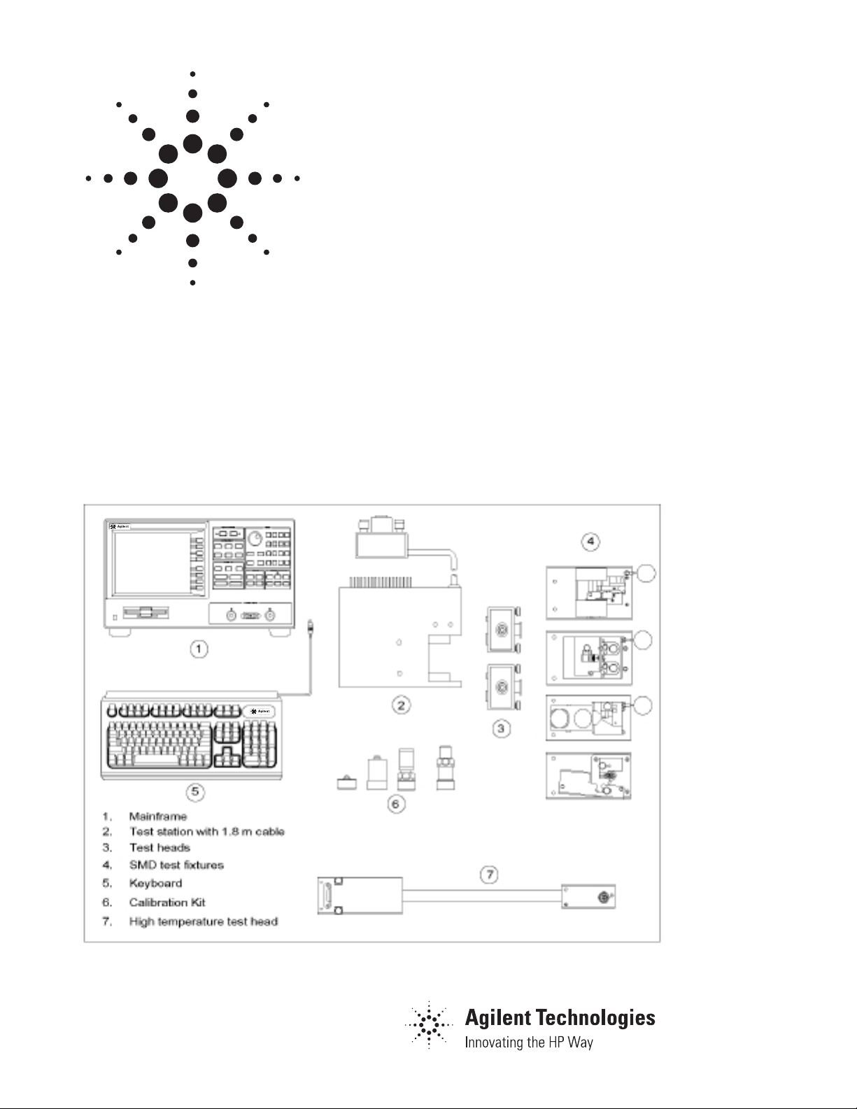
Agilent 4291B
RF Impedance/Material Analyzer
Data Sheet
Overview
Specifications describe the instrument’s warranted
performance over the temperature range of 0°C to
40°C (except as noted). Supplemental characteristics are intended to provide information that is
useful in applying the instrument by giving nonwarranted performance parameters.
These are denoted as “typical,” “nominal,” or
“approximate.” Warm-up time must be greater than
or equal to 30 minutes after power on for all specifications. Specifications of the stimulus characteristics and measurement accuracy are defined at
the tip of APC-7 connector on the test head connected to the instrument.
Figure 1-1

Agilent 4291B RF Impedance/Material Analyzer
Measurement Parameters
Impedance parameters
|Z|, θ
, |Y|, θ
z
Stimulus Characteristics
Frequency Characteristics
Operating frequency . . . . . . . . . . . . . . . . . . . . . . . . . . . . . . . . . . . . . . . . . . . . . . . . . . . . . . . . . 1 MHz to 1.8 GHz
Frequency resolution . . . . . . . . . . . . . . . . . . . . . . . . . . . . . . . . . . . . . . . . . . . . . . . . . . . . . . . . . . . . . . . . . 1 mHz
Frequency reference
Accuracy
@ 23±5°C . . . . . . . . . . . . . . . . . . . . . . . . . . . . . . . . . . . . . . . . . . . . . . . . . . . . . . . . . . . . . . . . . < ±10 ppm
Precision frequency reference (Option 1D5)
Accuracy
@ 0°C to 40°C . . . . . . . . . . . . . . . . . . . . . . . . . . . . . . . . . . . . . . . . . . . . . . . . . . . . . . . . . . . . . . < ±1 ppm
Source Characteristics
OSC level
Voltage range
@ 1 MHz ≤ Frequency ≤ 1 GHz (When terminal is open) . . . . . . . . . . . . . . . . . . . . . 0.2 mV
@ 1 GHz < Frequency ≤ 1.8 GHz (When terminal is open) . . . . . . . . . . . . . . . . . . . 0.2 mV
, R, X, G, B, Cp, Cs, Lp, Ls, Rp, R
y
, D, Q, |Γ|, θy, Γx, Γ
s
y
to 1 V
rms
rms
to 0.5 V
rms
rms
Current range
@ 1 MHz ≤ Frequency ≤ 1 GHz (When terminal is shorted). . . . . . . . . . . . . . . . . . . 4
@ 1 GHz < Frequency ≤ 1.8 GHz (When terminal is shorted). . . . . . . . . . . . . . . . . . 4
µ
A
rms
µ
A
rms
Power range
@ 1 MHz ≤ Frequency ≤ 1 GHz (When terminating with 50 Ω). . . . . . . . . . . . . . . . . –67 dBm to 7 dBm
@ 1 GHz < Frequency ≤ 1.8 GHz (When terminating with 50 Ω) . . . . . . . . . . . . . . . –67 dBm to 1 dBm
OSC level resolution
AC voltage resolution
0.22 V
70 mV
22 mV
7 mV
2.2 mV
0.7 mV
0.2 mV
rms
rms
rms
rms
rms
rms
rms
< V
< V
< V
< V
< V
< V
≤ V
OSC
OSC
OSC
OSC
OSC
OSC
OSC
≤ 1 V
rms
≤ 220 mV
≤ 70 mV
≤ 22 mV
≤ 7 mV
≤ 2.2 mV
≤ 0.7 mV
. . . . . . . . . . . . . . . . . . . . . . . . . . . . . . . . . . . . . . . . . . . . . . . . . . . . . . . . . . 2 mV
. . . . . . . . . . . . . . . . . . . . . . . . . . . . . . . . . . . . . . . . . . . . . . . . . . . . 0.5 mV
rms
. . . . . . . . . . . . . . . . . . . . . . . . . . . . . . . . . . . . . . . . . . . . . . . . . . . . . . 0.2 mV
rms
. . . . . . . . . . . . . . . . . . . . . . . . . . . . . . . . . . . . . . . . . . . . . . . . . . . . . . 0.05 mV
rms
. . . . . . . . . . . . . . . . . . . . . . . . . . . . . . . . . . . . . . . . . . . . . . . . . . . . . 0.02 mV
rms
. . . . . . . . . . . . . . . . . . . . . . . . . . . . . . . . . . . . . . . . . . . . . . . . . . . 0.005 mV
rms
. . . . . . . . . . . . . . . . . . . . . . . . . . . . . . . . . . . . . . . . . . . . . . . . . . . 0.002 mV
rms
to 20 mA
to 10 mA
rms
rms
2

Agilent 4291B RF Impedance/Material Analyzer
AC current resolution
4.4 mA
1.4 mA
0.44 mA
140
44
µ
14
µ
4
µ
A
AC power resolution . . . . . . . . . . . . . . . . . . . . . . . . . . . . . . . . . . . . . . . . . . . . . . . . . . . . . . . . . . . . . . 0.1 dBm
OSC level accuracy . . . . . . . . . . . . . . . . . . . . . . . . . . . . . . . . . . . . . . . . . . . . . . . . . . . . . A + B +
where,
A depends on temperature conditions as follows:
@ within referenced to 23±5°C . . . . . . . . . . . . . . . . . . . . . . . . . . . . . . . . . . . . . . . . . . . . . . . . . . 2 dB
@ other environmental temperature conditions. . . . . . . . . . . . . . . . . . . . . . . . . . . . . . . . . . . . . . 4 dB
B depends on OSC level as follows:
@ V
(I
(P
rms
rms
rms
µ
A
rms
A
rms
A
rms
≤ I
rms
OSC
≥ 5 mA
OSC
≥ –5 dBm)
OSC
< I
OSC
< I
OSC
< I
OSC
< I
OSC
< I
≤ 140
OSC
< I
≤ 44
OSC
≤ 14
OSC
≥ 250 mV
rms
≤ 20 mA
≤ 4.4 mA
≤ 1.4 mA
≤ 440
µ
µ
A
µ
A
rms
. . . . . . . . . . . . . . . . . . . . . . . . . . . . . . . . . . . . . . . . . . . . . . . . . . . . . . 40 µA
rms
. . . . . . . . . . . . . . . . . . . . . . . . . . . . . . . . . . . . . . . . . . . . . . . . . . . . . . 10 µA
rms
. . . . . . . . . . . . . . . . . . . . . . . . . . . . . . . . . . . . . . . . . . . . . . . . . . . . . . 4 µA
rms
µ
yA
. . . . . . . . . . . . . . . . . . . . . . . . . . . . . . . . . . . . . . . . . . . . . . . . . . . . . . 1 µA
rms
A
. . . . . . . . . . . . . . . . . . . . . . . . . . . . . . . . . . . . . . . . . . . . . . . . . . . . . . . 0.4 µA
rms
. . . . . . . . . . . . . . . . . . . . . . . . . . . . . . . . . . . . . . . . . . . . . . . . . . . . . . . 0.1 µA
rms
. . . . . . . . . . . . . . . . . . . . . . . . . . . . . . . . . . . . . . . . . . . . . . . . . . . . . . . 0.04 µA
6
. . . . . . . . . . . . . . . . . . . . . . . . . . . . . . . . . . . . . . . . . . . . . . . . . . . . . . . . . . . . 0 dB
rms
)
[dB]
f
1800
[MHz]
dB
@ 250 mV
(5 mA
rms
(–5 dBm > P
rms
> I
OSC
OSC
> V
OSC
≥ 2.5 mV
≥ 50
≥ –45 dBm)
. . . . . . . . . . . . . . . . . . . . . . . . . . . . . . . . . . . . . . . . . . . . . . . . . . 1 dB
rms
µ
A
)
rms
@ other OSC level . . . . . . . . . . . . . . . . . . . . . . . . . . . . . . . . . . . . . . . . . . . . . . . . . . . . . . . . . . . . . 2 dB
Definition of OSC level
• Voltage level: 2 voltage level across the 50 Ω which is connected to the output terminal (This level is
approximately equal to the level when a terminal is open.)
• Current level: 2 current level through the 50 Ω which is connected to the output terminal (This level is
approximately equal to the level when a terminal is shorted.)
• Power level: when terminating with 50 Ω
OSC level accuracy . . . . . . . . . . . . . . . . . . . . . . . . . . . . . . . . . . . . . . . . . . . . .
1
/2 of specification value (typical)
Connector . . . . . . . . . . . . . . . . . . . . . . . . . . . . . . . . . . . . . . . . . . . . . . . . . . . . . . . . . . . . . . . . . . . . . . . . . APC-7
Output impedance . . . . . . . . . . . . . . . . . . . . . . . . . . . . . . . . . . . . . . . . . . . . . . . . . . . . . . . 50 Ω (Nominal value)
DC bias (Option 001)
DC voltage level . . . . . . . . . . . . . . . . . . . . . . . . . . . . . . . . . . . . . . . . . . . . . . . . . . . . . . . . . . . . . . . . . . . . . . . . . . . 0 to ±40V
DC current level . . . . . . . . . . . . . . . . . . . . . . . . . . . . . . . . . . . . . . 20
DC level resolution . . . . . . . . . . . . . . . . . . . . . . . . . . . . . . . . . . . . . . . . . . . . . . . . . . . . . . . . . . . . 1 mV, 20
µ
A to 100 mA and –20 µA to –100 mA
µ
A
DC level accuracy
@ 23±5°C
Voltage . . . . . . . . . . . . . . . . . . . . . . . . . . . . . . . . . . . . . . . . . . . . . . . . 0.1 % + 4 mV + (I
Current. . . . . . . . . . . . . . . . . . . . . . . . . . . . . . . . . . . . . . . . . . . . . . . 0.5 % + 30
µ
A + (V
dc [mA]
dc [V]
5
/10
[Ω]
[kΩ]
) mV
) mA
@ 8 to 18°C and 28 to 38°C
Voltage . . . . . . . . . . . . . . . . . . . . . . . . . . . . . . . . . . . . . . . . . . . . . . . 0.2 % + 8 mV + (I
Current . . . . . . . . . . . . . . . . . . . . . . . . . . . . . . . . . . . . . . . . . . . . . . . . . 1 % + 60
µ
A + (V
dc [mA]
dc [v]
10
/5
[Ω]
[kΩ]
) mV
) mA
@ 0 to 8°0C and 38 to 40°C
Voltage . . . . . . . . . . . . . . . . . . . . . . . . . . . . . . . . . . . . . . . . . . . . . 0.3 % + 12 mV + (I
Current . . . . . . . . . . . . . . . . . . . . . . . . . . . . . . . . . . . . . . . . . . . . 1.5 % + 90
µ
A + (V
dc [V]
dc [mA]
3/10
15
[Ω]
[kΩ]
) mV
) mA
3

Agilent 4291B RF Impedance/Material Analyzer
Level monitor
Monitor parameters . . . . . . . . . . . . . . . . . . . . . . . . . OSC level (voltage, current), DC bias (voltage, current)
Monitor accuracy
OSC level . . . . . . . . . . . . . . . . . . . . . . . . . . . . . . . . . . . . . . . . . . . . Same as OSC level accuracy (typical)
DC bias . . . . . . . . . . . . . . . . . . . . . . . . . . Twice as bad as specifications of dc level accuracy (typical)
Sweep Characteristics
Figure 1-2. DC Voltage and Current Level Range (Typical)
Sweep parameters . . . . . . . . . . . . . . . . . . . . . . . . . . . Frequency, OSC level (voltage), DC bias voltage/current
Sweep setup . . . . . . . . . . . . . . . . . . . . . . . . . . . . . . . . . . . . . . . . . . . . . . . . . . . . . . . Start Stop, or Center Span
Sweep type
Frequency sweep . . . . . . . . . . . . . . . . . . . . . . . . . . . . . . . . . . . . . . . . . . . . . . . Linear, Log, Zero-span, List
Other sweep parameters . . . . . . . . . . . . . . . . . . . . . . . . . . . . . . . . . . . . . . . . . . . . . Linear, Log, Zero-span
Sweep mode . . . . . . . . . . . . . . . . . . . . . . . . . . . . . . . . . . . . . . . Continuous, Single, Manual, Number of groups
Sweep direction
AC level, DC bias (voltage and current) . . . . . . . . . . . . . . . . . . . . . . . . . . . . . . . . . Up sweep, Down sweep
Other sweep parameters . . . . . . . . . . . . . . . . . . . . . . . . . . . . . . . . . . . . . . . . . . . . . . . . . . . . . . . . Up sweep
Number of measurement points . . . . . . . . . . . . . . . . . . . . . . . . . . . . . . . . . . . . . . . . . . . . . . . . . . . 2 to 801 points
Averaging . . . . . . . . . . . . . . . . . . . . . . . . . . . . . . . . . . . . . . . . . . . . . . . . . . . . . . Sweep average, Point average
Delay time . . . . . . . . . . . . . . . . . . . . . . . . . . . . . . . . . . . . . . . . . . . . . . . . . . Point delay time, Sweep delay time
Measurement circuit mode . . . . . . . . . . . . . . . . . . . . . . . . . . . . . . . . . Series circuit mode, parallel circuit mode
Calibration/Compensation
Calibration function . . . . . . . . . . . . . . . . . . . . . . . . . . . . . . . Open/Short/50 Ω calibration, Low loss calibration
Compensation function . . . . . . . . . . . . . . . . . .Open/Short/Load compensation, Port extension, Electric length
4

Agilent 4291B RF Impedance/Material Analyzer
Measurement Accuracy
Conditions of accuracy specifications
• Open/Short/50 Ω calibration must be done. Calibration ON.
• Averaging (on point) factor is larger than 32 at which calibration is done if Cal points is set to
USER DEF.
• Measurement points are same as the calibration points.
• Environmental temperature is within ±5°C of temperature at which calibration is done, and within l3°C
to 33°C. Beyond this environmental temperature condition, accuracy is twice as bad as specified.
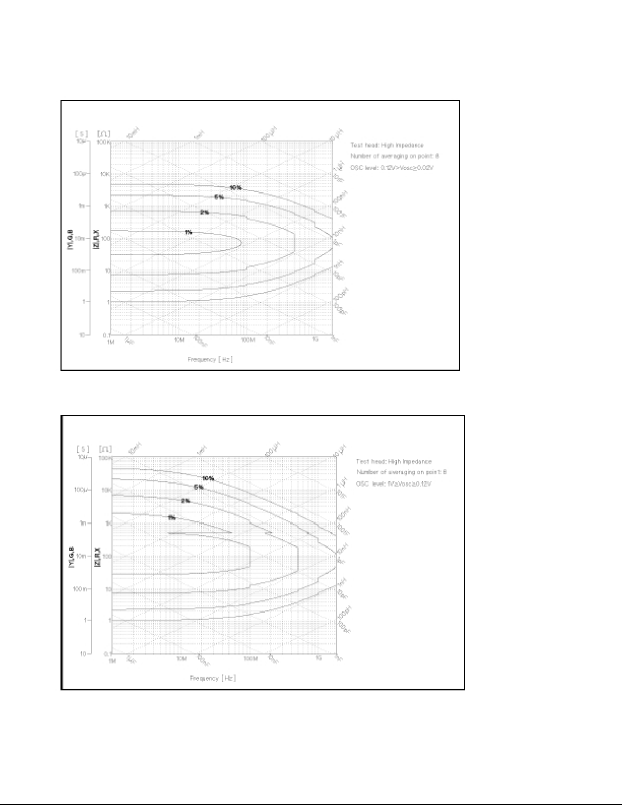
|Z|, |Y| Accuracy . . . . . . . . . . . . . . . . . . . . . . . . . . . . . . . . . . . . . . . . . . . . . . . . . . . . . . . . . ±(E
The illustrations of |Z| and |Y| accuracy are shown in Figures l-3 to 1-6.
θ Accuracy . . . . . . . . . . . . . . . . . . . . . . . . . . . . . . . . . . . . . . . . . . . . . . . . . . . . . . . . . . . . . . ±
L, C, X, B Accuracy . . . . . . . . . . . . . . . . . . . . . . . . . . . . . . . . . . . . . . . . . . . . . . . . . . ±(E
R, G Accuracy . . . . . . . . . . . . . . . . . . . . . . . . . . . . . . . . . . . . . . . . . . . . . . . . . . . . . . ±(E
a
a
D Accuracy (∆D)
Ea+ E
@ |D
tan ( )| < 1 . . . . . . . . . . . . . . . . . . . . . . . . . . . . . . . . . . . . . . . . . . . . ± .
x
Especially, @ D
Q Accuracy (∆Q)
@ |Q
tan ( )| < 1. . . . . . . . . . . . . . . . . . . . . . . . . . . . . . . . . . . . . . . . . . . . . ± .
x
Especially, @ ≥ Q
(E
b
100
≤ 0.1. . . . . . . . . . . . . . . . . . . . . . . . . . . . . . . . . . . . . . . . . . . . . . . . . . . . . . . . ±
x
Ea + E
b
100
10
+ Eb)
a
≥ 10 . . . . . . . . . . . . . . . . . . . . . . . . . . . . . . . . . . . . . . . . . . . . . . . . . . . ±Q
x
+ Eb) [%]
a
(E
+ Eb)
a
100
+ Eb) (1 + D
+ Eb) (1 + Q
(1 + D
2
)tan ( )
x
1 Dxtan ( )
E
(E
[rad]
2
x
2
x
E
a
100
+ E
a
100
+ Eb)
a
) [%]
) [%]
+ E
b
100
+ E
E
(1 + Q
2
)tan ( )
x
(1 Qx)tan ( )
a
100
+ E
E
a
100
(Ea + Eb)
2
x
100
b
b
b
±
Where,
D
: Measured vaulue of D
x
E
: depends on measurement frequency as follows:
a
@ 1 MHz ≤ Frequency ≤ 100 MHz . . . . . . . . . . . . . . . . . . . . . . . . . . . . . . . . . . . . . . . . . . . . . . . . . . . . 0.6
@ 100 MHz < Frequency ≤ 500 MHz . . . . . . . . . . . . . . . . . . . . . . . . . . . . . . . . . . . . . . . . . . . . . . . . . . 0.8
@ 500 MHz < Frequency ≤ 1000 MHz . . . . . . . . . . . . . . . . . . . . . . . . . . . . . . . . . . . . . . . . . . . . . . . . . 1.2
@ 1000 MHz < Frequency ≤ 1800 MHz . . . . . . . . . . . . . . . . . . . . . . . . . . . . . . . . . . . . . . . . . . . . . . . . 2.0
E
= (Zs/|Zx| + Yo|Zx| 100
b
Q
: Measured value of Q
x
Z
: impedance measurement value [Ω]
x
Z
and Yodepend on number of point averaging (Nav), OSC level (V
s
value (Z
) and the test head used as follows:
x
), impedance measurement
OSC
5

Agilent 4291B RF Impedance/Material Analyzer
Table 1-1. Zsand YoWhen High Impedance Test Head Is Used
Measurement Conditions
Number
of Point Meas.
Averaging OSC Signal Level Impedance
(Nav)(V
1 ≤ N
≤ 7 0.02V ≤ V
av
)(Z
osc
V
< 0.02V – x (0.2 + 0.001 x f
osc
< 0.12V – 0.2 + 0.001 x f
osc
)Z
x
[Ω]Y
S
0.02
V
osc
[MHz]
[S]
o
0.02
) x (5 x 10⁻⁵+ 2 x 10⁻⁷x f
[MHz]
V
osc
5 x 10⁻⁵+ 2 x 10⁻⁷x f
[MHz]
[MHz]
)
N
≥ 8 0.02V ≤ V
av
0.12V ≤ V
0.12V ≤ V
osc
V
< 0.02V – x (0.1 + 5 x 10⁻⁴x f
osc
< 0.12V – 0.1 + 5 x 10⁻⁴x f
osc
osc
Z
≥ 500 Ω 0.2 + 0.001 x f
x
Z
< 500 Ω 0.2 + 0.001 x f
x
Z
≥ 500 Ω 0.1 + 5 x 10
x
Z
< 500 Ω 0.1 + 5 x 10
x
Table 1-2. Zsand YoWhen Low Impedance Test Head Is Used
Measurement Conditions
Number
of Point Meas.
Averaging OSC Signal Level Impedance
(Nav)(V
1 ≤ N
≤ 7 0.02V ≤ V
av
)(Z
osc
V
< 0.02V – x (0.1 + 0.001 x f
osc
< 0.12V – 0.1 + 0.001 x f
osc
0.12V ≤ V
osc
)Z
x
Z
≤ 5 Ω 0.01 + 0.001 x f
x
[MHz]
[MHz]
0.02
V
osc
[MHz]
–4
x f
[MHz]
–4
x f
[MHz]
[Ω] Y
S
0.02
V
osc
[MHz]
[MHz]
5 x 10⁻⁶+ 2 x 10⁻⁷x f
2 x 10⁻⁵+ 2 x 10⁻⁷x f
0.02
) x (2 x 10
[MHz]
V
osc
2 x 10
2 x 10
7 x 10
o
0.02
) x (1 x 10⁻⁴+ 2 x 10⁻⁷x f
[MHz]
V
osc
[S]
–5
+ 1 x 10
–6
+ 1 x 10
–6
+ 1 x 10
–5
+ 1 x 10
1 x 10⁻⁴+ 2 x 10⁻⁷x f
1 x 10⁻⁴+ 2 x 10⁻⁷x f
[MHz]
[MHz]
–7
x f
)
[MHz]
–7
x f
[MHz]
–7
x f
[MHz]
–7
x f
[MHz]
)
[MHz]
[MHz]
[MHz]
Z
N
≥ 8 0.02V ≤ V
av
0.12V ≤ V
> 5 Ω 0.05 + 0.001 x f
x
V
< 0.02V – x (0.05 + 5 x 10
osc
< 0.12V – 0.05 + 5 x 10⁻⁴x f
osc
Z
osc
≤ 5 Ω 0.01 + 5 x 10
x
Z
> 5 Ω 0.02 + 5 x 10
x
0.02
V
osc
[MHz]
–4
x f
[MHz]
[MHz]
–4
x f
[MHz]
–4
x f
[MHz]
1 x 10⁻⁴+ 2 x 10⁻⁷x f
0.02
) x (3 x 10⁻⁵+ 1 x 10⁻⁷x f
V
osc
3 x 10⁻⁵+ 1 x 10⁻⁷x f
3 x 10⁻⁵+ 1 x 10⁻⁷x f
3 x 10⁻⁵+ 1 x 10⁻⁷x f
[MHz]
[MHz]
[MHz]
[MHz]
[MHz]
At the following frequency points, instrument spurious characteristics could occasionally cause measurement errors to exceed specified value because of instrument spurious characteristics.
10.71 MHz 17.24 MHz 21.42 MHz 42.84 MHz
514.645 MHz 686.19333 MHz 1029.29 MHz 1327.38666 MHz
See “EMC” under “Others” in “General Characteristics.”
6
Agilent 4291B RF Impedance/Material Analyzer
Figure 1-3. Impedance Measurement Accuracy Using High Impedance Test Head (@ Low OSC Level)
Figure 1-4. Impedance Measurement Accuracy Using High Impedance Test Head (@ High OSC Level)
7

Agilent 4291B RF Impedance/Material Analyzer
Figure 1-5. Impedance Measurement Accuracy Using Low Impedance Test Head (@ Low OSC Level)
Figure 1-6. Impedance Measurement Accuracy Using Low Impedance Test Head (@ High OSC Level)
8

Agilent 4291B RF Impedance/Material Analyzer
Typical measurement accuracy when open/short/50 Ω/low-loss-capaciter calibration is done
Conditions
• Averaging on point factor is larger than 32 at which calibration is done.
• Cal Points is set to USER DEF.
• Environmental temperature is within ±5°C of temperature at which calibration is done, and within 13°C
to 33°C. Beyond this environmental temperature condition, accuracy is twice as bad as specified.
|Z|, |Y| Accuracy . . . . . . . . . . . . . . . . . . . . . . . . . . . . . . . . . . . . . . . . . . . . . . . . . . . . . . . . . . . ±(E
θ Accuracy . . . . . . . . . . . . . . . . . . . . . . . . . . . . . . . . . . . . . . . . . . . . . . . . . . . . . . . . . . . . . . . . . ± [rad]
L, C, X, B Accuracy . . . . . . . . . . . . . . . . . . . . . . . . . . . . . . . . . . . . . . . . . . . . . . . . ± (E
R, G Accuracy . . . . . . . . . . . . . . . . . . . . . . . . . . . . . . . . . . . . . . . . . . . . . . . . . . . . ± (E
+ Eb)2+ (EcDx)2[%]
a
+ Eb)2+ (EcQx)2[%]
a
+ Eb) [%]
a
E
c
100
D Accuracy
2
@ |D
Especially, D
tan(Ec/100)| < 1 . . . . . . . . . . . . . . . . . . . . . . . . . . . . . . . . . . . . . . . . . . . . . . . ± ±
x
x
Q Accuracy
@ |Q
tan(Ec/100)| < 1 . . . . . . . . . . . . . . . . . . . . . . . . . . . . . . . . . . . . . . . . . . . . . . ± .
x
Especially, ≥ Q
10
E
≤ 0.1 . . . . . . . . . . . . . . . . . . . . . . . . . . . . . . . . . . . . . . . . . . . . . . . . . . . . . . . . . . . . ± ±
≥ 10 . . . . . . . . . . . . . . . . . . . . . . . . . . . . . . . . . . . . . . . . . . . . . . . . . . . . . ± Q
c
x
(1 + Dx) tan(Ec/100)
1D
tan(Ec/100)
x
E
c
100
2
(1 + Qx)tan(Ec/100)
1 Q
tan(Ec/100)
x
2
x .
E
100
Where,
D
: Actual D value of DUT
X
E
, Eb: are as same as Eaand E
a
is done.
E
= 0.06 + 0.14 (Typical)
c
F
1800
of the measurement accuracy when OPEN/SHORT/50 Ω calbration
b
F : measurement frequency [MHz]
Q
: Actual Q value of DUT
x
c
9

Agilent 4291B RF Impedance/Material Analyzer
Figure 1-7. Typical measurement accuracy when open/short/50 Ω/low-loss-capaciter calibration is done
10

Options 013 and 014 High Temperature Test Heads
Specification for Option 013 and 014 High Temperature Test Heads
Frequency Characteristics
Operating frequency . . . . . . . . . . . . . . . . . . . . . . . . . . . . . . . . . . . . . . . . . . . . . . . . . . . . . . . 1 MHz to 1.8 GHz
Source Characteristics
OSC level
Voltage Range
@ 1 MHz ≤ Frequency < 1 GHz . . . . . . . . . . . . . . . . . . . . . . . . . . . . . . . . . . . . 0.2 mV
@ 1 GHz ≤ Frequency ≤ 1.8 GHz . . . . . . . . . . . . . . . . . . . . . . . . . . . . . . . . . . . . . 0.2 mV
OSC level resolution
AC voltage resolution
@ 110 mV
@ 11 mV
@ 1.1 mV
@ 0.2 mV
rms
rms
rms
rms
< V
< V
< V
≤ V
OSC
≤ 110 mV
OSC
OSC
OSC
≤ 500 mV
≤ 11 mV
≤ 1.1 mV
. . . . . . . . . . . . . . . . . . . . . . . . . . . . . . . . . . . . . . . . . . . . . . . . . . 2 mV
rms
. . . . . . . . . . . . . . . . . . . . . . . . . . . . . . . . . . . . . . . . . . . . . . . . . 0.2 mV
rms
. . . . . . . . . . . . . . . . . . . . . . . . . . . . . . . . . . . . . . . . . . . . . . . . . . . 20 µV
rms
. . . . . . . . . . . . . . . . . . . . . . . . . . . . . . . . . . . . . . . . . . . . . . . . . . . 2 µV
rms
AC current resolution
@ 2.75 mA
@ 0.275 mA
@ 27.5
@ 5
µ
A ≤ I
µ
< I
OSC
< I
OSC
OSC
≤ 27.5
≤12.5 mA
≤ 2.75 mA
≤ 275
µ
µ
A . . . . . . . . . . . . . . . . . . . . . . . . . . . . . . . . . . . . . . . . . . . . . . . . . . . . . . 0.05 µA
rms
rms
A
< I
rms
OSC
. . . . . . . . . . . . . . . . . . . . . . . . . . . . . . . . . . . . . . . . . . . . . . . . . 50 µA
rms
. . . . . . . . . . . . . . . . . . . . . . . . . . . . . . . . . . . . . . . . . . . . . . . . 5 µA
rms
A
. . . . . . . . . . . . . . . . . . . . . . . . . . . . . . . . . . . . . . . . . . . . . . . . . 0.5 µA
rms
AC power resolution
@ –66.1 dBm ≤ P
≤ 1.9 dBm . . . . . . . . . . . . . . . . . . . . . . . . . . . . . . . . . . . . . . . . . . . . 0.2 dBm max
OSC
OSC level accuracy
@ 1 MHz ≤ Frequency ≤ 1 GHz, V
. . . . . . . . . . . . . . . . . . . . . . . . . . . . . . . . . . . . . . . . . . . . . . . . . . . . A + B + dB
OSC
≤ 0.25 V
rms(IOSC
≤ 6.3 mA, P
≤ –4.1 dBm)
OSC
8[dB] frequency[
Where,
to 500 mV
rms
rms
1800
250 mV
MHz
rms
rms
]
A depends on temperature conditions as follows:
within referenced to 23±5°C . . . . . . . . . . . . . . . . . . . . . . . . . . . . . . . . . . . . . . . . . . . . . . . . . . . . . 4 dB
@ 0°C to 18°C, 28°C to 40°C . . . . . . . . . . . . . . . . . . . . . . . . . . . . . . . . . . . . . . . . . . . . . . . . . . . . 6 dB
B depends on OSC level as follows:
@ 0.5 V
(12.5 mA
(1.9 dBm ≥ P
@ 120 mV
(3 mA
(–10 dBm > P
@ 1.2 mV
(30
(–50 dBm > P
≥ V
rms
rms
rms
> I
rms
rms
µ
A
> I
rms
≥ 120 mV
OSC
≥ I
≥ 3mA
OSC
≥ –10 dBm)
OSC
> V
OSC
≥ 30
OSC
≥ –50 dBm)
OSC
> V
OSC
≥ 5
OSC
≥ –66.1 dBm)
OSC
rms
≥ 1.2 mV
µ
A
)
rms
≥ 0.2 mV
µ
A
)
rms
. . . . . . . . . . . . . . . . . . . . . . . . . . . . . . . . . . . . . . . . . . . . . . . . . . . . 0 dB
rms
)
. . . . . . . . . . . . . . . . . . . . . . . . . . . . . . . . . . . . . . . . . . . . . . . . . . 1 dB
rms
. . . . . . . . . . . . . . . . . . . . . . . . . . . . . . . . . . . . . . . . . . . . . . . . . . . 2 dB
rms
Output impedance . . . . . . . . . . . . . . . . . . . . . . . . . . . . . . . . . . . . . . . . . . . . . . . . . . . . . . . . . . . . . . . . 40 Ω (Nominal value)
Level Monitor
Monitor accuracy
OSC level . . . . . . . . . . . . . . . . . . . . . . . . . . . . . . . . . . . . . . . . . . . Same as OSC level accuracy (typical)
DC bias . . . . . . . . . . . . . . . . . . . . . . . . . . . Twice as bad as specifications of dc level accuracy (typical)
11

Options 013 and 014 High Temperature Test Heads
Basic Measurement Accuracy
Conditions of accuracy specifications
• OPEN/SHORT/50 Ω calibration must be done. Calibration ON.
• Averaging (on point) factor must be larger than 32 at which calibration is done.
• Measurement points are same as the calibration points.
• Environmental temperature is within ±5°C of temperature at which calibration is done, and within 13°C
to 33°C. Beyond this environmental temperature condition, and within 0°C to 40°C, accuracy is twice as
bad as specified.
• Bending cable should be smooth and the bending angle is less than 30°.
• Cable position should be kept in the same position after calibration measurement.
• OSC level must be same as level at which calibration is done.
• OSC level is less than or equal to 0.25 V, or OSC level is greater than 0.25 V and frequency range is
within 1 MHz to 1 GHz.
|Z| Accuracy . . . . . . . . . . . . . . . . . . . . . . . . . . . . . . . . . . . . . . . . . . . . . . . . . . . . . . . . . . . . . . . . . ±(E
θ Accuracy . . . . . . . . . . . . . . . . . . . . . . . . . . . . . . . . . . . . . . . . . . . . . . . . . . . . . . . . . . . . . . . . ± [rad]
+ Eb) [%]
a
(Ea+ Eb)
100
Where,
E
: depends on measurement frequency as follows:
a
@ 1 MHz ≤ frequency ≤ 100 MHz . . . . . . . . . . . . . . . . . . . . . . . . . . . . . . . . . . . . . . . . . . . . . . . 0.6 [%]
@ 100 MHz < frequency ≤ 500 MHz . . . . . . . . . . . . . . . . . . . . . . . . . . . . . . . . . . . . . . . . . . . . . 0.8 [%]
@ 500 MHz < frequency ≤ 1 GHz . . . . . . . . . . . . . . . . . . . . . . . . . . . . . . . . . . . . . . . . . . . . . . . . 1.5 [%]
@ 1 GHz < frequency ≤ 1.8 GHz . . . . . . . . . . . . . . . . . . . . . . . . . . . . . . . . . . . . . . . . . . . . . . . . 3.0 [%]
E
= (Zs/Zx+ YoZx) 100 [%]
b
Z
and Yodepend on number of point averaging (Nav) and OSC level (V
s
Z
: Impedance measurement value [Ω]
x
) as follows:
osc
12

Options 013 and 014 High Temperature Test Heads
Table 1-3. Zsand YoWhen High Impedance Test Head Is Used
Measurement Conditions
Number
of Point
Averaging OSC Signal Level
(Nav)(V
1 ≤ N
≤ 7 0.02V ≤ V
av
8 < N
av
1
)
osc
0.12V ≤ V
0.02V ≤ V
Z
[Ω]Y
S
V
< 0.02 x (0.2 + 0.001 x f
osc
< 0.12 0.2 + 0.001 x f
osc
osc
V
< 0.02 x (0.1 + 0.001 x f
osc
< 0.12 0.1 + 0.001 x f
osc
0.02
V
osc
0.2 + 0.001 x f
0.02
V
osc
[MHz]
[MHz]
[MHz]
[MHz]
[MHz]
[S]
o
0.02
) x (5 x 10⁻⁵+ 2 x 10⁻⁷x f
V
osc
–5
5 x 10
+ 2 x 10⁻⁷x f
–6
3 x 10
+ 2 x 10⁻⁷x f
) x (2 x 10⁻⁵+ 2 x 10⁻⁷x f
0.02
V
osc
2 x 10⁻⁵+ 2 x 10⁻⁷x f
[MHz]
[MHz]
[MHz]
[MHz]
[MHz]
)
)
1. V
= 0.12V l
osc
= 3 mA P
osc
0.12V ≤ V
= –10 dBm, V
OSC
osc
= 0.02V l
osc
= 0.5 mA P
osc
= –26 dBm
osc
Table 1-4. Zsand YoWhen Low Impedance Test Head Is Used
Measurement Conditions
Number
of Point
Averaging OSC Signal Level
(Nav)(V
1 ≤ Nav≤ 7 0.02V ≤ V
8 < N
av
1. V
= 0.12V l
osc
= 3 mA P
osc
1
)
osc
0.12V ≤ V
0. 02V ≤ V
0.12V ≤ V
= –10 dBm, V
OSC
V
< 0.02 x (0.1 + 0.001 x f
osc
< 0.12 0.1 + 0.001 x f
osc
osc
V
< 0.02 x (0.05 + 0.001 x f
osc
< 0.12 0.05 + 0.001 x f
osc
osc
= 0.02V l
osc
= 0.5 mA P
osc
= –26 dBm
osc
0.1 + 0.001 x f
Z
[Ω] Y
S
0.02
V
osc
[MHz]
[MHz]
0.05 + 0.001 x f
0.02
V
osc
0.03 + 0.001 x f
2 x 10⁻⁵+ 2 x 10⁻⁷x f
[S]
o
0.02
) x (1 x 10⁻⁴+ 2 x 10⁻⁷x f
[MHz]
V
osc
1 x 10⁻⁴+ 2 x 10⁻⁷x f
[MHz]
[MHz]
[MHz]
[MHz]
1 x 10⁻⁴+ 2 x 10⁻⁷x f
0.02
) x (3 x 10⁻⁵+ 2 x 10⁻⁷x f
V
osc
3 x 10⁻⁵+ 2 x 10⁻⁷x f
3 x 10⁻⁵+ 2 x 10⁻⁷x f
[MHz]
[MHz]
[MHz]
[MHz]
[MHz]
[MHz]
[MHz]
)
)
At the following frequency points, instrument spurious characteristics could occasionally cause measurement errors to exceed specified value because of instrument spurious characteristics.
10.71 MHz 17.24 MHz 21.42 MHz 42.84 MHz
514.645 MHz 686.19333 MHz 1029.29 MHz 1327.38666 MHz
See “EMC” under “Others” in “General Characteristics.”
The excessive vibration and shock could occasionally cause measurement errors to exceed specified values.
13
Options 013 and 014 High Temperature Test Heads
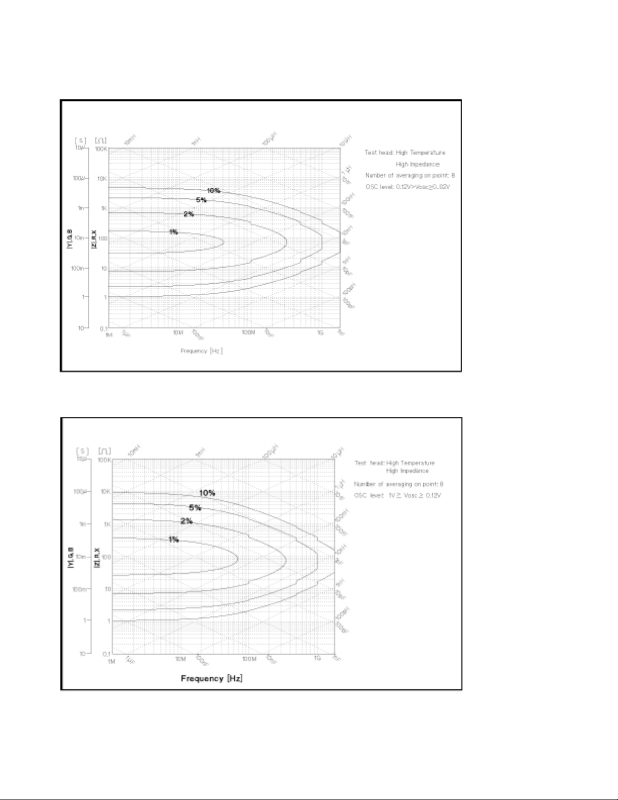
Figure 1-8. Impedance Measurement Accuracy Using High Temperature High Impedance Test Head (@ Low OSC Level)
Figure 1-9. Impedance Measurement Accuracy Using High Temperature High Impedance Test Head (@ High OSC Level)
14
Options 013 and 014 High Temperature Test Heads
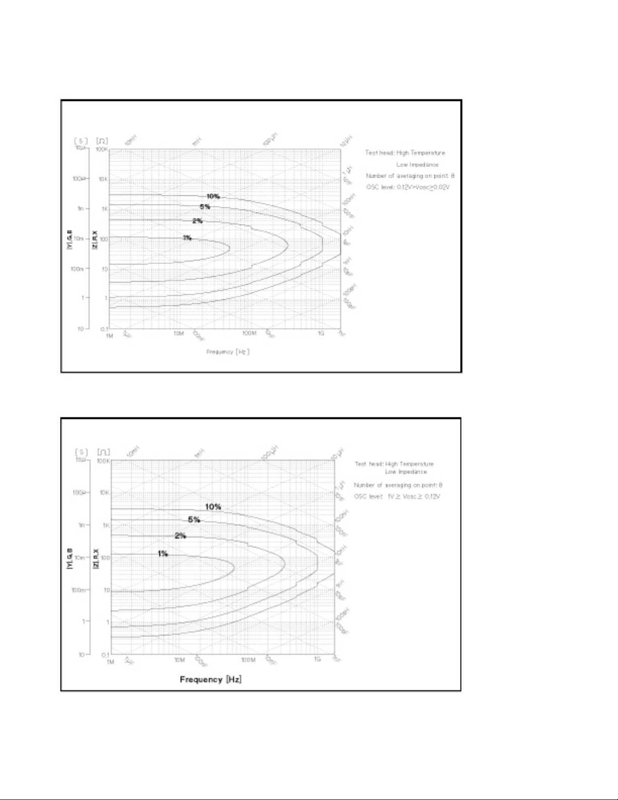
Figure 1-10. Impedance Measurement Accuracy Using High Temperature Low Impedance Test Head (@ Low OSC Level)
Figure 1-11. Impedance Measurement Accuracy Using High Temperature Low Impedance Test Head (@ High OSC Level)
15

Options 013 and 014 High Temperature Test Heads
Typical Effects of Temperature Drift on Measurement Accuracy
When environmental temperature exceeds ±5°C of temperature at which calibration is done, add the
following measurement error.
Conditions of typical effects of temperature drift
• Environment temperature of a test head is within –55°C to 0°C or 40°C to 200°C.
• Environment temperature of the mainframe is within ±5°C of temperature at which calibration is done,
and within 0°C to 40°C.
• Other conditions are as same as the conditions of the basic measurement accuracy of Option 013/014.
|Z| Accuracy . . . . . . . . . . . . . . . . . . . . . . . . . . . . . . . . . . . . . . . . . . . . . . . . . . . . . . . . . . . . . . . ±(E
θ Accuracy . . . . . . . . . . . . . . . . . . . . . . . . . . . . . . . . . . . . . . . . . . . . . . . . . . . . . . . . . . . . . . . ± [rad]
+ Eb2) [%]
a2
(Ea2+ Eb2)
100
Where,
E
= (∆A1∆T + ∆A
a2
2
) 10
8
Eb2= (Zs2/Zx+ Yo2Zx) 100
∆A
is the effect of temperature drift on the impedance measurement value as follows:
1
(50 + 300 f ) [ppm/°C] (typical)
∆A
is the hysterisiss of the effect of temperature drift on the impedance measurement value as follows:
2
∆A1∆T
[ppm] (typical)
3
f : Measurement Frequency [GHz]
∆T: Difference of temperature between measurement condition and calibration measurement condition. [°C]
Y
= (∆Yo1∆T + ∆Y
o2
Z
= (∆Zs1∆T + ∆Z
s2
Z
: Impedance measurement value [Ω]
x
Y
is the temperature coefficient for OPEN residual as follows:
o1
@ High Temperature High Impedance Test Head is used . . . . . . . . . (0.2 + 8 f
@ High Temperature Low Impedance Test Head is used . . . . . . . . . . (1 + 30 f ) [
Y
is the hysterisis of the OPEN residual as follows: . . . . . . . . . . . . . . . . . . . [µS/°C](typical)
o2
) 10–6[S]
o2
s2
) 10
–3
[Ω]
2
) [µS/°C] (typical)
µ
S/°C] (typical)
∆Y01∆T
3
16
∆Z
is the temperature coefficient for SHORT residual as follows:
s1
@ High Temperature High Impedance Test Head is used . . . . . . . . . . (4 + 50 f ) [mΩ°C] (typical)
∆Zs1∆T
3
2
) [mΩ°C] (typical)
@ High Temperature Low Impedance Test Head is used . . . . . . . . . . (1 + 10 f
∆Z
is the hysterisis of the SHORT residual as follows: . . . . . . . . . . . . . . . . [mΩ/°C](typical)
s2

Options 013 and 014 High Temperature Test Heads
Figure 1-12. Typical Frequency Characteristics of Temperature Coefficient Using High Temperature High Impedance Test Head
Figure 1-13. Typical Frequency Characteristics of Temperature Coefficient Using High Temperature Low Impedance Test Head
17

Options 013 and 014 High Temperature Test Heads
Operation Conditions of the Test Head
• The cable must be at the same temperature as the main frame at least 15 cm from the test station.
. . . . . . . . . . . . . . . . . . . . . . . . . . . . . . . . . . . . . . . . . . . . . . . . . . . . . . . . . . . . . . . . . . . . . . . 55°C to +200°C
Figure 1-14. Dimensions of High Temperature Test Head
18

Options 013 and 014 High Temperature Test Heads
Display
LCD
Type/size . . . . . . . . . . . . . . . . . . . . . . . . . . . . . . . . . . . . . . . . . . . . . . . . . . . . . . . . . . . Color TFT, 8.4 inch
Resolution . . . . . . . . . . . . . . . . . . . . . . . . . . . . . . . . . . . . . . . . . . . . . . . . . . . . . . . . . . . . . . . . . . 640 480
Effective Display Area . . . . . . . . . . . . . . . . . . . . . . . . . . . . . . . . . . . . 160 mm 115 mm (600 430 dots)
Number of display channels . . . . . . . . . . . . . . . . . . . . . . . . . . . . . . . . . . . . . . . . . . . . . . . . . . . . . . . . . . . . . . . 2
Format . . . . . . . . . . . . . . . . . . . . . . . . . . . . . . . . . . . . . single, dual split or overwrite, graphic, and tabular
Number of traces
For measurement . . . . . . . . . . . . . . . . . . . . . . . . . . . . . . . . . . . . . . . . . . . . . . . . . . . . . . . 1 trace/channel
For memory . . . . . . . . . . . . . . . . . . . . . . . . . . . . . . . . . . . . . . . . . . . . . . . 16 traces/channel (maximum)
Data math functions . . . . . . . . . . . . . . . . . . . . . . . . . . . . . . . . . . . . . . . . . . . . . . . . . . . . . . . gain data-offset
gain memory – offset
gain (data – memory) – offset
gain (data + memory) – offset
gain (data/memory) – offset
gain (data memory) – offset
Marker
Number of markers
Main marker . . . . . . . . . . . . . . . . . . . . . . . . . . . . . . . . . . . . . . . . . . . . . . . . . . . . . .1 for each channel
Sub-marker . . . . . . . . . . . . . . . . . . . . . . . . . . . . . . . . . . . . . . . . . . . . . . . . . . . . . . . 7 for each channel
∆Marker . . . . . . . . . . . . . . . . . . . . . . . . . . . . . . . . . . . . . . . . . . . . . . . . . . . . . . . . . .1 for each channel
Data Storage
Type . . . . . . . . . . . . . . . . . . . . . . . . . . . . . . . . . . . . . . . . . . . . . . . . floppy disk drive, Volatile memory disk
Capacity
floppy disk . . . . . . . . . . . . . . . . . . . . . . . . . . . . . . . . . . . . . . . . . . . . . . . . . . . . . . . . . . . . 720 kB/1.44 MB
Volatile memory disk, can be backed up by flash memory . . . . . . . . . . . . . . . . . . . 448 kB (maximum)
Disk format . . . . . . . . . . . . . . . . . . . . . . . . . . . . . . . . . . . . . . . . . . . . . . . . . . . . . . . . . . . . . . . . . . . . . . . . . . . . . . . LIF, DOS
GPIB
Interface . . . . . . . . . . . . . . . . . . . . . . . . . . . . . . . . . . . . . . . . . . . . . . . . . . . . . . . . . . . IEEE 488.1-1987, IEC625
Interface function . . . . . . . . . . . . . . . . . . . . . . . . . . . . . . . . . . . . . . . . . . . SH1, AH1, T6, TE0, L4, LE0, SR1, RL1, PPO,
DC1, DT1, C1, C2, C3, C4, C11, E2
Numeric Data Transfer formats . . . . . . . . . . . . . . . . . . . . . . . . . . . . . . . . . . . . . . . . . . . . . . . . . . . . . . . . . . . ASCII
32 and 64 bit IEEE 754 Floating point format,
DOS PC format (32 bit IEEE with byte order reversed)
Protocol . . . . . . . . . . . . . . . . . . . . . . . . . . . . . . . . . . . . . . . . . . . . . . . . . . . . . . . . . . . . . . . . . . IEEE 488.2-1987
19

Options 013 and 014 High Temperature Test Heads
Printer Parallel Port
Interface . . . . . . . . . . . . . . . . . . . . . . . . . . . . . . . . . . . . . . . . . . . IEEE 1284 Centronics standard compliant
Printer control language. . . . . . . . . . . . . . . . . . . . . . . . . . . . . . . . . . . . . . HP PCL3 Printer Control Language
Connector . . . . . . . . . . . . . . . . . . . . . . . . . . . . . . . . . . . . . . . . . . . . . . . . . . . . . . . . . . . . . . . . . D-sub (25-pin)
General Characteristics
Input and Output Characteristics
External reference input
Frequency . . . . . . . . . . . . . . . . . . . . . . . . . . . . . . . . . . . . . . . . . . . . . . . . . . . . 10 MHz ±100 Hz (typically)
Level. . . . . . . . . . . . . . . . . . . . . . . . . . . . . . . . . . . . . . . . . . . . . . . . . . . . . . . . . . . . . . > –6 dBm (typically)
Input impedance . . . . . . . . . . . . . . . . . . . . . . . . . . . . . . . . . . . . . . . . . . . . . . . . . . . . . . . . . 50 Ω (nominal)
Connector . . . . . . . . . . . . . . . . . . . . . . . . . . . . . . . . . . . . . . . . . . . . . . . . . . . . . . . . . . . . . . . . . BNC female
Internal Reference Output
Frequency . . . . . . . . . . . . . . . . . . . . . . . . . . . . . . . . . . . . . . . . . . . . . . . . . . . . . . . . . . . 10 MHz (nominal)
Level . . . . . . . . . . . . . . . . . . . . . . . . . . . . . . . . . . . . . . . . . . . . . . . . . . . . . . . . . . . . . . . . 2 dBm (typically)
Output impedance . . . . . . . . . . . . . . . . . . . . . . . . . . . . . . . . . . . . . . . . . . . . . . . . . . . . . . . . 50 Ω (nominal)
Connector . . . . . . . . . . . . . . . . . . . . . . . . . . . . . . . . . . . . . . . . . . . . . . . . . . . . . . . . . . . . . . . . . BNC female
External trigger input
Level . . . . . . . . . . . . . . . . . . . . . . . . . . . . . . . . . . . . . . . . . . . . . . . . . . . . . . . . . . . . . . . . . . . . . . TTL Level
Pulse width (Tp) . . . . . . . . . . . . . . . . . . . . . . . . . . . . . . . . . . . . . . . . . . . . . . . . . . . . . . . . > 2
Polarity . . . . . . . . . . . . . . . . . . . . . . . . . . . . . . . . . . . . . . . . . . . . . . . . . . . . . . positive/negative selective
Connector . . . . . . . . . . . . . . . . . . . . . . . . . . . . . . . . . . . . . . . . . . . . . . . . . . . . . . . . . . . . . . . . . BNC female
µ
s (typically)
Figure 1-15. Trigger Signal
External monitor output
Connector . . . . . . . . . . . . . . . . . . . . . . . . . . . . . . . . . . . . . . . . . . . . . . . . . . . . . . . D-sub (15-pin HD)
Display resolution . . . . . . . . . . . . . . . . . . . . . . . . . . . . . . . . . . . . . . . . . . . . . . . . . 640 480 VGA
20

Options 013 and 014 High Temperature Test Heads
Operation Conditions
Temperature
Disk drive non-operating condition . . . . . . . . . . . . . . . . . . . . . . . . . . . . . . . . . . . . . . . . . . . 0°C to 40°C
Disk drive operating condition . . . . . . . . . . . . . . . . . . . . . . . . . . . . . . . . . . . . . . . . . . . . . . 10°C to 40°C
Humidity
@ wet bulb temperature <29°C, without condensation
Disk drive non-operating condition . . . . . . . . . . . . . . . . . . . . . . . . . . . . . . . . . . . . . . 15 % to 95 % RH
Disk drive operating condition . . . . . . . . . . . . . . . . . . . . . . . . . . . . . . . . . . . . . . . . . . 15 % to 80 % RH
Altitude . . . . . . . . . . . . . . . . . . . . . . . . . . . . . . . . . . . . . . . . . . . . . . . . . . . . . . . . . . . . . . . . 0 to 2,000 meters
Warm-up time . . . . . . . . . . . . . . . . . . . . . . . . . . . . . . . . . . . . . . . . . . . . . . . . . . . . . . . . . . . . . . . . 30 minutes
Non-operation conditions
Temperature . . . . . . . . . . . . . . . . . . . . . . . . . . . . . . . . . . . . . . . . . . . . . . . . . . . . . . . . . . . . . . . –20°C to 60°C
Humidity
@ wet bulb temperature <45°C, without condensation . . . . . . . . . . . . . . . . . . . . . . . . . 15 % to 95 % RH
Altitude . . . . . . . . . . . . . . . . . . . . . . . . . . . . . . . . . . . . . . . . . . . . . . . . . . . . . . . . . . . . . . . . 0 to 4,572 meters
Others
EMC . . . . . . . . . . . . . . . . . . . . . . . Complies with CISPR 11 (1990) / EN 55011 (1991) : Group 1, Class A
. . . . . . . . . . . . . . . . . . . . . . . . . . . . . . . . . Complies with IEC 1000-3-2 (1995) / EN 61000-3-2 (1995)
. . . . . . . . . . . . . . . . . . . . . . . . . . . . . . . . . Complies with IEC 1000-3-3 (1994) / EN 61000-3-3 (1995)
. . . . . . . . . . . . . . . . . . Complies with IEC 1000-4-2 (1995) / EN 50082-1 (1992) : 4 kV CD, 8 kV AD
. . . . . . . . . . . . . . . . . . . . . . . . . . . . Complies with IEC 1000-4-2 (1995) / EN 50082-1 (1992) : 3 V/m
. . . . . . Complies with IEC 1000-4-4 (1995) / EN 50082-1 (1992) : 1 kV / Main, 0.5k V / Signal Line
Note: When tested at 3 V/m according to IEC 1000-4-3 (1995), the measurement accuracy will be within specifications over the full immunity test frequency range of 27 to
1000 MHz except when the analyzer frequency is identical to the transmitted interference signal test frequency.
Safety . . . . . . . . . . . . Complies with IEC 1010-1 (1990), Amendment 1 (1992) and Amendment 2 (1995).
. . . . . . . . . . . . . . . . . . . . . . . . . . . . . . . . . . . . . . . . . . . . . . . Complies with CSA-C22.2 No. 1010.1-92.
Power requirements . . . . . 90V to 132V, or 198V to 264V (automatically switched), 47 to 63 Hz, 300VA max
Weight
Mainframe . . . . . . . . . . . . . . . . . . . . . . . . . . . . . . . . . . . . . . . . . . . . . . . . . . . . . . . . . . . . . . 21.5 kg (SPC)
Test Station . . . . . . . . . . . . . . . . . . . . . . . . . . . . . . . . . . . . . . . . . . . . . . . . . . . . . . . . . . . . . . . . . . . 3.7 kg
Dimensions
Mainframe . . . . . . . . . . . . . . . . . . . . . . . . . . . . . . . . . . . . . . . . . . . . . 425 (W) 235 (H) 553 (D) mm
Test Station . . . . . . . . . . . . . . . . . . . . . . . . . . . . . . . . . . . . . . . . . . . . . . 275 (W) 95 (H) 205 (D) mm
21

Options 013 and 014 High Temperature Test Heads
External Program Run/Cont Input
Connector . . . . . . . . . . . . . . . . . . . . . . . . . . . . . . . . . . . . . . . . . . . . . . . . . . . . . . . . . . . . . . . . . . . BNC female
Level . . . . . . . . . . . . . . . . . . . . . . . . . . . . . . . . . . . . . . . . . . . . . . . . . . . . . . . . . . . . . . . . . . . . . . . . . . . . . TTL
Keyboard connector . . . . . . . . . . . . . . . . . . . . . . . . . . . . . . . . . . . . . . . . . . . . . . . . . . . . . . . . . . . . . . mini-DIN
I/O port . . . . . . . . . . . . . . . . . . . . . . . . . . . . . . . . . . . . . . . . . . . . . . . . . . . 4 bit in/ 8 bit out port, TTL Level
Figure 1-16. I/O Port Pin Assignment
Specifications for Option 1D5 High Stability Frequency Reference
Reference Oven Output
Frequency . . . . . . . . . . . . . . . . . . . . . . . . . . . . . . . . . . . . . . . . . . . . . . . . . . . . . . . . . . . . . . 10 MHz (nominal)
Level . . . . . . . . . . . . . . . . . . . . . . . . . . . . . . . . . . . . . . . . . . . . . . . . . . . . . . . . . . . . . . . . . . 0 dBm (typically)
Output Impedance . . . . . . . . . . . . . . . . . . . . . . . . . . . . . . . . . . . . . . . . . . . . . . . . . . . . . . . . . . 50 Ω (nominal)
Connector . . . . . . . . . . . . . . . . . . . . . . . . . . . . . . . . . . . . . . . . . . . . . . . . . . . . . . . . . . . . . . . . . . . BNC female
22

Option 002 Material Measurement
Supplemental Characteristics for Option 002 Material Measurement
Measurement Frequency Range
Using the Agilent 16453A . . . . . . . . . . . . . . . . . . . . . . . . . . . . . . . . . . . . . . . . . 1 MHz to 1.0 GHz (Typical)
Using the Agilent 16454A . . . . . . . . . . . . . . . . . . . . . . . . . . . . . . . . . . . . . . . . . 1 MHz to 1.0 GHz (Typical)
Measurement Parameters
Permittivity parameters . . . . . . . . . . . . . . . . . . . . . . . . . . . . . . . . . . . . . . . . . . . . . . . . . . . . . . |ε
Permeability parameters . . . . . . . . . . . . . . . . . . . . . . . . . . . . . . . . . . . . . . . . . . . . . . . . . . . . |
Typical Measurement Accuracy
Conditions of accuracy characteristics
• Use the High Z Test Head for permittivity measurement
• Use the Low Z Test Head for permeability measurement
• OPEN/SHORT/50 Ω calibration must be done. Calibration ON.
• Averaging (on point) factor is larger than 32 at which calibration is done if Cal points is set to
USER DEF.
• Measurement points are same as the calibration points if Cal point is set to USER DEF.
• Environment temperature is within ±5°C of temperature at which calibration is done, and within 13°C to
33°C. Beyond this environmental temperature condition, accuracy is twice as bad as specified.
|, εr', εr", tanδ
r
µ
|,
µ
',
µ
r
r
r
", tanδ
∆ε'
ε
' Accuracy ( )
r
@ tanδ < 0.1. . . . . . . . . . . . . . . . . . . . . . . 5 + (10 + ) + 0.25 + [%] (Typical)
Loss Tangent Accuracy of (∆tanδ)
@ tanδ < 0.1 . . . . . . . . . . . . . . . . . . . . . . . . . . . . . . . . . . . . . . . . . . . . . . . . . . . . . . . . . . . E
rm
ε'
rm
0.04
A
ε
r
t
ε'
f
rm
ε'
rm
t
100
|1 – (13/ ε'
2
/f)
|
rm
+ Eb(Typical)
a
Where,
@ frequency ≤ 1 GHz
E
= 0.002 + + 0.004f + (Typical)
a
0.0004
f
t
ε'
m
|1 – (13/ ε'
0.1
rm
/f)
2
|
@ frequency > 1 GHz
∆ε'
ε'
rm
rm
0.0004
f
1
100
E
= 0.002 + + 0.004f + (Typical)
a
E
= ( + ε'
b
rm
t
ε'
m
0.002
) tanδ (Typical)
t
0.1
|1 – (13/ ε'
rm
/f)
2
|
f is measurement frequency [GHz]
t is thickness of MUT [mm]
ε'
is measured value of ε'
rm
r
tanδ is measured value of dielectric loss tangent
23

Option 002 Material Measurement
∆µ'
µ
' Accuracy
r
@ tanδ < 0.1 . . . . . . . . . . . . . . . . . . . . . . . . . . . . . . . . . . . . . 4 + + Fµ'
Loss Tangent Accuracy of
@ tanδ < 0.1 . . . . . . . . . . . . . . . . . . . . . . . . . . . . . . . . . . . . . . . . . . . . . . . . . . . . . . . . . . . . . E
rm
µ'
rm
A
µ
(∆tanδ)
r
Fµ'
25
rm
(1 + )2f2[%] (Typical)
rm
Fµ'
15
rm
+ Eb(Typical)
a
Where,
E
= 0.002 + + 0.004 f (Typical)
a
∆µ'
E
= (Typical)
b
µ'
rm
rm
0.001
Fµ'
tanδ
100
rm
f
f is measurement frequency [GHz]
F = hln [mm]
c
b
h is the height of MUT [mm]
b is the inner diameter of MUT
c is the outer diameter of MUT
tanδ is the measured value of loss tangent
µ'
is the measured value of permeability
rm
At the following frequency points, instrument spurious characteristics could occasionally cause measurement errors to exceed specified value.
10.71 MHz 17.24 MHz 21.42 MHz 42.84 MHz
514.645 MHz 686.19333 MHz 1029.29 MHz 1327.38666 MHz
See “EMC” under “Others” in “General Characteristics.”
24

Option 002 Material Measurement
Figure 1-17. Typical Permittivity Measurement Accuracy (@ thickness = 0.3 mm)
Figure 1-18. Typical Permittivity Measurement Accuracy (@ thickness = 1 mm)
25

Option 002 Material Measurement
Figure 1-19. Typical Permittivity Measurement Accuracy (@ thickness = 3 mm)
Figure 1-20. Typical Dielectric Loss Tangent (tanδ) Measurement Accuracy (@ thickness = 0.3 mm)
26

Option 002 Material Measurement
Figure 1-21. Typical Dielectric Loss Tangent (tanδ) Measurement Accuracy (@ thickness = 1 mm)
Figure 1-22. Typical Dielectric Loss Tangent (tanδ) Measurement Accuracy (@ thickness = 3 mm)
27

Option 002 Material Measurement
Figure 1-23. Typical Permittivity Measurement Accuracy (ε
vs. Frequency, @ thickness = 0.3 mm)
r
Figure 1-24. Typical Permittivity Measurement Accuracy (ε
28
vs. Frequency, @ thickness = 1 mm)
r

Option 002 Material Measurement
Figure 1-25. Typical Permittivity Measurement Accuracy (ε
vs. Frequency, @ thickness = 3 mm)
r
29

Option 002 Material Measurement
Figure 1-26. Typical Permeability Measurement Accuracy (@ F* = 0.5)
Figure 1-27. Typical Permeability Measurement Accuracy (@ F* = 3) *F = hln
30
c
b

Option 002 Material Measurement
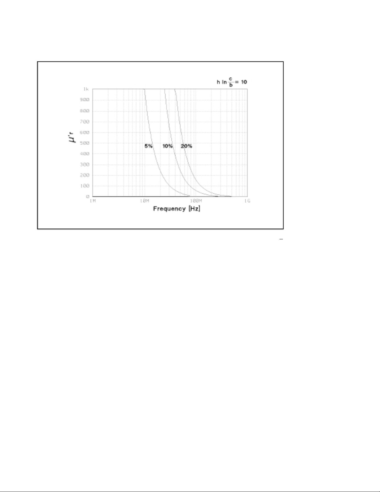
Figure 1-28. Typical Permeability Measurement Accuracy (@ F* = 10)
Figure 1-29. Typical Permeability Loss Tangent (tanδ) Measurement Accuracy (@ F* = 0.5) *F = hln
c
b
31

Option 002 Material Measurement
Figure 1-30. Typical Permeability Loss Tangent (tanδ) Measurement Accuracy (@ F* = 3)
Figure 1-31. Typical Permeability Loss Tangent (tanδ) Measurement Accuracy (@ F* = 10) *F = hln
32
c
b

Option 002 Material Measurement
Figure 1-32. Typical Permeability Measurement Accuracy (
µ
vs. Frequency, @ F* = 0.5)
r
Figure 1-33. Typical Permeability Measurement Accuracy (
µ
vs. Frequency, @ F* = 3) *F = hln
r
c
b
33
Option 002 Material Measurement
Figure 1-34. Typical Permeability Measurement Accuracy (
µ
vs. Frequency, @ F* = 10) *F = hln
r
c
b
34

Option 002 Material Measurement
Applicable MUT (Material Under Test) Size . . . . . . . . . . . . . . . . . . . . . . . . . . . . . . . . . . . . . See Tables 1-5 and 1-6
Maximum DC Bias Voltage / Current
Using the Agilent 16453A . . . . . . . . . . . . . . . . . . . . . . . . . . . . . . . . . . . . . . . . . . . . . . . . . . . . . . . . . . . ±40 V
Using the Agilent 16454A . . . . . . . . . . . . . . . . . . . . . . . . . . . . . . . . . . . . . . . . . . . . . . . . . . . . . . . . ±500 mA
Operating Temperature
Using the Agilent 16453A or 16454A . . . . . . . . . . . . . . . . . . . . . . . . . . . . . . . . . . . . . . . . –55°C to +200°C
Operating Humidity
Wet bulb temperature < 40°C
Using the Agilent 16453A or 16454A . . . . . . . . . . . . . . . . . . . . . . . . . . . . . . . . . . . . . . . . . up to 95% RH
Table 1-5. Applicable Dielectric Material Size Using with the Agilent 16453A
t ≤ 3 mm
d ≥
φ
15 mm
Table 1-6. Applicable Magnetic Material Size Using the Agilent 16454A
Fixture Small Large
Holder A B C D
c ≤φ8 mm ≤φ6 mm ≤φ20 mm ≤
b ≥φ 3.1 mm ≥φ 3.1 mm ≥φ6 mm ≥
h ≤ 3 mm ≤3 mm ≤ 10 mm ≤ 10 mm
φ
20 mm
φ
5 mm
35

Material Measurement Accuracy with High Temperature Test Head
Option 002 Material Measurement Accuracy with Options 013 and 014 High Temperature
Test Head (Typical)
Dielectric Material Measurement Accuracy with High Temperature Test Head (Typical)
Conditions of Dielectric Material Measurement Accuracy with High Temperature Test Head
• Environment temperature is within ±5°C of temperature at which calibration is done, and within
0°C to 40°C.
• High Temperature High Impedance Test Head must be used.
• Bending cable should be smooth and the bending angle less than 30°.
• Cable position should be kept in the same position after calibration measurement.
• OPEN/SHORT/50 Ω calibration must be done. Calibration ON.
• Measurement points are same as the calibration points.
• Averaging (on point) factor must be larger than 32 at which calibration is done.
• OSC level must be same as level at which calibration is done.
• OSC level is less than or equal to 0.25 V
to 1 GHz.
• Environment temperature of the main frame is within ±5°C of temperature at which calibration is done,
and within 0°C to 40°C.
, or greater than 0.25 V
rms
and frequency range is within 1 MHz
rms
∆ε'
ε
' Accuracy ( ). . . . . . . . . . . . . . . . . . . . . . . . . . Same as accuracy at which a normal test head is used
r
Loss Tangent Accuracy of ε
rm
ε'
rm
A
(∆tanδ) . . . . . . . . . . . . . . . Same as accuracy at which a normal test head is used
r
At the following frequency points, instrument spurious characteristics could occasionally cause measurement errors to exceed specified value.
10.71 MHz 17.24 MHz 21.42 MHz 42.84 MHz
514.645 MHz 686.19333 MHz 1029.29 MHz 1327.38666 MHz
See “EMC” under “Others” in “General Characteristics.”
The excessive vibration and shock could occasionally cause measurement errors to exceed specified value.
36

Material Measurement Accuracy with High Temperature Test Head
Typical Effects of Temperature Drift on Dielectric Material Measurement Accuracy
When environment temperature is without ±5°C of temperature at which calibration is done, add the
following measurement error.
∆ε'
ε
’ Accuracy ( ) . . . . . . . . . . . . . . . . . . . . . . . . . . . . . . . . . . . . . . . . . . . . . . . . . . . . . . . . . Eε+ Ea3+ E
r
Loss Tangent Accuracy of ε
Where,
E
is ε
ε
E
tanδε
E
a3
E
E
b3
E
rm
ε'
rm
A
(∆tanδ) . . . . . . . . . . . . . . . . . . . . . . . . . . . . . . . . . . . . . . . . . . . . . . . E
r
' accuracy when a normal test head is used.
r
is loss tangent accuracy when a normal test head is used.
is the effect of temperature drift on the accuracy as follows:
= T
∆T
a3
c
is the hysterisis of the effect of temperature drift on the accuracy as follows:
= T
∆T
b3
c
3
tanδε
(E
a3 + Eb3
b3
100
[%]
+
)
Where,
T
is temperature coefficient as follows:
c
T
= K1 + K2 + K
c
K1 = 1 10
K
= 3 10
2
K
= 5 10
3
3
–6
(50 + 300f)
ε'
–6
(4 + 50f) ( + 10) f
–3
(0.2 + 8f2)
rm
t
ε'
rm
(
t
1
|1 – (f/f
1
|1 – (f/f
)2|
0
1
)2|
0
+ 10) f
f : Measurement Frequency [GHz]
13
f
= [GHz]
0
ε'
rm
t : Thickness of MUT [mm]
ε'
: measured value of ε'
rm
r
The illustrations of temperature coefficient Tcare shown in Figures 1-35 to 1-37.
∆T is difference of temperature between measurement condition and calibration measurement condition
as follows:
∆T = |T
T
meas
T
cal
– T
meas
cal
|
: Temperature of Test Head at measurement condition
: Temperature of Test Head at calibration measurement condition
37

Material Measurement Accuracy with High Temperature Test Head
Figure 1-35. Typical Frequency Characteristics of Temperature Coefficient of ε
(Thickness = 0.3 mm)
’ and Loss Tangent Accuracy
r
38

Material Measurement Accuracy with High Temperature Test Head
Figure 1-36. Typical Frequency Characteristics of Temperature Coefficient of ε
(Thickness = 1 mm)
’ and Loss Tangent Accuracy
r
39

Material Measurement Accuracy with High Temperature Test Head
Figure 1-37. Typical Frequency Characteristics of Temperature Coefficient of ε
(Thickness = 3 mm)
’ and Loss Tangent Accuracy
r
40

Material Measurement Accuracy with High Temperature Test Head
Material Measurement Accuracy with High Temperature Test Head (Typical)
Conditions of Dielectric Material Measurement Accuracy with High Temperature Test Head
• Environment temperature is within ±5°C of temperature at which calibration is done, and within 0°C to
40°C.
• High Temperature Low Impedance Test Head must be used.
• Bending cable should be smooth and the bending angle less than 30°.
• Cable position should be kept in the same position after calibration measurement.
• OPEN/SHORT/50 Ω calibration must be done. Calibration ON.
• Measurement points are same as the calibration points.
• Averaging (on point) factor must be larger than 32 at which calibration is done.
• OSC level must be same as level at which calibration is done.
• OSC level is less than or equal to 0.25 V
1 MHz to 1 GHz.
• Environment temperature of the main frame is within ±5°C of temperature at which calibration is done,
and within 0°C to 40°C.
∆
µ
'
µ
' Accuracy ( ) . . . . . . . . . . . . . . . . . . . . . . . . . . Same as accuracy at which a normal test head is used
r
Loss Tangent Accuracy of
rm
µ
'
rm
µ
'(∆tanδ) . . . . . . . . . . . . . . . Same as accuracy at which a normal test head is used
r
At the following frequency points, instrument spurious characteristics could occasionally cause measurement errors to exceed specified value.
10.71 MHz 17.24 MHz 21.42 MHz 42.84 MHz
514.645 MHz 686.19333 MHz 1029.29 MHz 1327.38666 MHz
, or greater than 0.25 V
rms
and frequency range is within
rms
See “EMC” under “Others” in “General Characteristics.”
The excessive vibration and shock could occasionally cause measurement errors to exceed specified value.
41

Material Measurement Accuracy with High Temperature Test Head
Typical Effects of Temperature Drift on Magnetic Material Measurement Accuracy
When environment temperature exceeds ±5°C of temperature at which calibration is done, add the
following measurement error.
∆
µ
'
µ
' Accuracy ( ) . . . . . . . . . . . . . . . . . . . . . . . . . . . . . . . . . . . . . . . . . . . . . . . . . . . . . . . . . . Eµ+ Ea3+ E
r
Loss Tangent Accuracy of
Where,
E
is µ'
µ
E
tanδµ
E
is the effect of temperature drift on the accuracy as follows:
a3
E
a3
*E
b3
E
b3
Where,
T
is temperature coefficient as follows:
c
rm
µ
'
rm
accuracy when a normal test head is used.
r
A
µ
'(∆tanδ) . . . . . . . . . . . . . . . . . . . . . . . . . . . . . . . . . . . . . . . . . . . . . . E
r
is loss tangent accuracy when a normal test head is used.
= T
∆T
c
is the hysterisis of the effect of temperature drift on the accuracy as follows:
= T
∆T
c
3
(Ea3+ Eb3)
+ =
tanδµ
b3
100
T
= K1 + K2 + K
c
K1 = 1 10
K
= 1 10–2 (1 + 10f2) + 10)f
2
K
= 2 10–6 (1 + 30f )
3
3
–6
(50 + 300f )
|1 – 0.01{F(
{F(
µ
{F(
µ
'rm– 1) + 20}f
|1 – 0.01{F(
µ
'rm– 1) + 10}f2|
'rm– 1) + 20}f
µ
'rm– 1) + 10}f2|
f : Measurement Frequency [GHz]
F = hln c [mm]
b
h is the height of MUT [mm]
b is the inner diameter of MUT
c is the outer diameter of MUT
µ
'rmis the measured value of permeability
The illustrations of temperature coefficient T
are shown in Figures 1-38 to 1-40.
c
∆T is difference of temperature between measurement condition and calibration measurement condition
as follows:
∆ T = |T
meas
– T
cal
|
T
: Temperature of Test Head at measurement condition
meas
T
: Temperature of Test Head at calibration measurement condition
cal
42

Material Measurement Accuracy with High Temperature Test Head
Figure 1-38. Typical Frequency Characteristics of Temperature Coefficient of µ
' and Loss Tangent Accuracy (F* = 0.5)
r
*F = hln
c
b
43

Material Measurement Accuracy with High Temperature Test Head
Figure 1-39. Typical Frequency Characteristics of Temperature Coefficient of µ
' and Loss Tangent Accuracy (F* = 3)
r
*F = hln
c
b
44

Material Measurement Accuracy with High Temperature Test Head
Figure 1-40. Typical Frequency Characteristics of Temperature Coefficient of µ
' I and Loss Tangent Accuracy (F* = 10)
r
*F = hln
c
b
45

Furnished Accessories
Accessory Agilent part number
Operating Manual 04291-90020
Programming Manual 04291-90027
Service Manual
1
04291-90111
Program Disk Set 04291-18000
Power Cable
2
50 Ω Termination 04291-65006
0 Ω Termination 04191-85300
0 S Termination 04191-85302
Low-Loss Capacitor 04291-60042
Calibration Kit Carrying Case 04291-60041
APC-7 End Cap 16190-25011
Fixture Stand
3
04291-60121
Pad 04291-09001
BNC Adapter
4
1250-1859
Mini-DIN Keyboard C3757-60401
Instrument BASIC User’s Handbook E2083-90000
Handle Kit
5
5062-3991
Rack Mount Kit
Rack Mount and Handle Kit
1. Option OBW only
2. The power cable depends on where the instrument is used;
see User’s Guide.
3. Option 013 and 014 only
4. Option 1D5 only
5. Option 1CN only
6. Option 1CM only
7. Option 1CP only
6
7
5062-3979
5062-3985
46


Agilent Technologies’ Test and Measurement
Support, Services, and Assistance
Agilent Technologies aims to maximize the value you receive,
while minimizing your risk and problems. We strive to ensure
that you get the test and measurement capabilities you paid
for and obtain the support you need. Our extensive support
resources and services can help you choose the right Agilent
products for your applications and apply them successfully.
Every instrument and system we sell has a global warranty.
Support is available for at least five years beyond the production life of the product. Two concepts underlie Agilent’s
overall support policy: “Our Promise” and “Your Advantage.”
Our Promise
“Our Promise” means your Agilent test and measurement equipment will meet its advertised performance and functionality.
When you are choosing new equipment, we will help you with
product information, including realistic performance specifications and practical recommendations from experienced test
engineers. When you use Agilent equipment, we can verify that
it works properly, help with product operation, and provide
basic measurement assistance for the use of specified capabilities, at no extra cost upon request. Many self-help tools are
available.
Your Advantage
“Your Advantage” means that Agilent offers a wide range of
additional expert test and measurement services, which you
can purchase according to your unique technical and business
needs. Solve problems efficiently and gain a competitive edge
by contracting with us for calibration, extra-cost upgrades, outof-warranty repairs, and on-site education and training, as well
as design, system integration, project management, and other
professional services. Experienced Agilent engineers and technicians worldwide can help you maximize your productivity,
optimize the return on investment of your Agilent instruments
and systems, and obtain dependable measurement accuracy
for the life of those products.
By internet, phone, or fax, get assistance with all your
test and measurement needs.
Online Assistance
www.agilent.com/find/assist
Phone or Fax
United States:
(tel) 1 800 452 4844
Canada:
(tel) 1 877 894 4414
(fax) (905) 282 6495
Europe:
(tel) (31 20) 547 2323
(fax) (31 20) 547 2390
Japan:
(tel) (81) 426 56 7832
(fax) (81) 426 56 7840
Latin America:
(tel) (305) 269 7500
(fax) (305) 269 7599
Australia:
(tel) 1 800 629 485
(fax) (61 3) 9210 5947
New Zealand:
(tel) 0 800 738 378
(fax) (64 4) 495 8950
Asia Pacific:
(tel) (852) 3197 7777
(fax) (852) 2506 9284
Product specifications and descriptions in this
document subject to change without notice.
Copyright © 1997, 2000 Agilent Technologies
Printed in U.S.A. 12/00
5966-1543E
 Loading...