

Page 1

MANUAL CHANGES
Agilent 4285A
Precision LCR Meter
Operation Manual
This supplement contains information for correcting manual errors and for adapting the manual to newer instruments that contains
improvements or modifications not doc umented in the existing manual.
To use this supplement
1. Make all ERRATA corrections
2. Make all appropriate serial-num ber-rel ated changes listed below
SERIAL PREFIX OR NUMBER MAKE MANUAL
CHANGES
All 1
New Item
K
SERIAL PREFIX OR NUMBER MAKE MANUAL
CHANGES
MANUAL IDENTIFICATION
Model Number: 4285A
Date Printed: March 2000
Part Number: 04285-90010
ERRATA
CHANGES 1
CHANGE 1 contains the information needed to adapt the 4285A’s manual.
Changed the company name from YOKOGAWA-HEWLETT-PACKARD, LTD., or its abbreviation YHP to Agilent
Technologies Japan, Ltd.
Manual change supplement are revised as often as nec essary to keep manuals as current and acc urate as possible. Agilent Technol ogies
recommends that you peri odi cally request the latest edition of this supplement. Free copies are available from al l Agilent Technologies offi ces.
When requesting copies , quote the m anual ident ific ation inform ation from your supplem ent, or the model number and print date f rom t he titl e
page of the manual.
Date/Div: March 2000/33
Page 1 of 3
PRINTED IN JAPAN
NOTE
Page 2

The pink sheet titled “CAUTION ON OPERATION”
Change the page title as follows.
CAUTION ON OPERATION
3.HANDLER INTERFACE BOARD (OPTION 201)
Add the following information.
Fuse: Non Time Delay 0.5A 125V
If you need this fuse,contact your nearest Agilent Technologies Sales and Service Office.
MODEL 4284A PRECISION LCR METER OPTION 201 HANDLER INTERFACE
OPERATION NOTE
Page 2-16 Warning
Change the procedure 1 and warning as follows:
1. Disconnect the 4284A’s power cord and allow 1 minute for the internal supply filter capacitors to
discharge.
Dangerous energy/voltage exists when the 4284A is in operation,and for a time after it is
powered down. Allow 1 minute for the internal capacitors to discharge.
Page 2-16
Add the following CAUTION after the procedure 7.
The interface board contains electronic components that can be damaged by static
electricity through electrostatic discharge(ESD).To prevent ESD damage,maintain frequent
contact with any bare sheet metal surface on the chassis. A grounding wrist strap (or similar
device) is useful for this purpose. Handle the board car efully at all times. Avoid touching
electronic components or circuit paths.
MODEL 4284A PRECISION LCR METER OPTION 202 HANDLER INTERFACE
OPERATION NOTE
Page 3-4 Warning
Change the procedure 1 and warning as follows:
1. Disconnect the 4284A’s power cord and allow 1 minute for the internal supply filter capacitors to
discharge.
Dangerous energy/voltage exists when the 4284A is in operation,and for a time after it is
powered down. Allow 1 minute for the internal capacitors to discharge.
Page 3

Page 3-4
Add the following CAUTION after the procedure 6.
The interface board contains electronic components that can be damaged by static
electricity through electrostatic discharge(ESD).To prevent ESD damage,maintain frequent
contact with any bare sheet metal surface on the chassis. A grounding wrist strap (or similar
device) is useful for this purpose. Handle the board car efully at all times. Avoid touching
electronic components or circuit paths.
MODEL 4284A PRECISION LCR METER OPTION 301 SCANNER INTERFACE
OPERATION NOTE
Page 2-11 Warning
Change the procedure 1 and warning as follows:
Disconnect the power cable from the 4284A and allow 1 minute for the internal capacitors to
discharge.
Dangerous energy/voltage exists when the 4284A is in operation,and for a time after it is
powered down. Allow 1 minute for the internal capacitors to discharge.
Page 4

Page 5

MANUAL CHANGES
Agilent 4285A
Precision LCR Meter
Operation Manual
This supplement contains information for correcting manual errors and for adapting the manual to newer instruments that contains
improvements or modifications not doc umented in the existing manual.
To use this supplement
1. Make all ERRATA corrections
2. Make all appropriate serial-num ber-rel ated changes listed below
SERIAL PREFIX OR NUMBER MAKE MANUAL
CHANGES
3041J00276 1
New Item
K
SERIAL PREFIX OR NUMBER MAKE MANUAL
CHANGES
MANUAL IDENTIFICATION
Model Number: 4285A
Date Printed: March 2000
Part Number: 04285-90010
ERRATA
CHANGES 1
When used with the 42851A Precision Q Adapter, make the following changes:
Two system messages are added.
"Warning, Cannot find resonance" (when the tuning capacitor cannot resonate with the DUT)
"Waiting for trigger" (when the 4285A is not triggered)
On the Q CORRECTION page, the SHORT correction function is always set to ON.
On the Q CORRECTION page, the Q-MODE field is added to select between EFFECTIVE Q mode and CIRCUIT
Q mode.
Manual change supplement are revised as often as nec essary to keep manuals as current and acc urate as possible. Agilent Technol ogies
recommends that you peri odi cally request the latest edition of this supplement. Free copies are available from al l Agilent Technologies offi ces.
When requesting copies , quote the m anual ident ific ation inform ation from your supplem ent, or the model number and print date f rom t he titl e
page of the manual.
Date/Div: March 2000/33
Page 1 of 1
PRINTED IN JAPAN
NOTE
Page 6

Page 7

CAUTIONS ON OPERATION
1. UNKNOWN (MEASUREMENT) TERMINA LS
Do NOT
NOT apply DC voltage or current to the UNKNOWN terminals. Doing so will damage
NOTNOT
the 4285A. Before you measure a capacitor, be sure the capacitor is fully discharged.
2. MEMORY CARD
Use Agilent Technologies-specified memory cards containing 4285A-specific data only. If
other memory cards are used, the 4285A may be damaged. Non 4285A-specific data
contained on a memory card is not guaranteed, and data may be lost.
To insert a memory card into the MEMORY
facing upward and with the contacts at the slot opening. Insert the card into the slot until
it "clicks" in place.
To remove a memory card from the 4285A, press the UNLOCK button and remove the
card.
Do NOT remove a memory card while LOADing or STORing d ata. Doing so may damage
the memory card and any data stored in the memory card may be lost.
Store memory cards in their furnished card cases when not in use. The card case protects
memory cards from contamination and electrostatic discharge.
Also, store memory cards under the following environmental conditions.
Storage Temperature Range: -30 ℃ to +70 ℃
Storage Humidity Range: 30%. to 85%. (@ +50 ℃)
MEMORY card slot, hold the memory card with the label
MEMORYMEMORY
Do NOT shock or stress memory cards.
When storing or moving your 4285A, be sure the memory card slot is empty (no memory
card inserted).
Do NOT touch the connector contact surface of a memory card and do NOT use chemical
liquids to clean the contacts.
Page 8
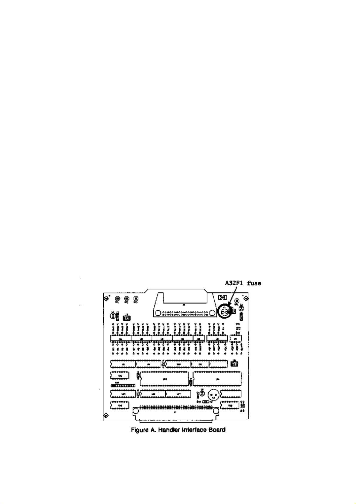
3. HANDLER INTERFACE BOARD (0PTION 201)
If the +5V internal voltage
output
output , a fuse on the handler interface board (A32F1) has blown and must be replaced.
outputoutput
Two replacement fuses are furnished with the 4285A option 201. Additional fuses are
available from Agilent Technologies. Order PN 2110-0046.
Fuse: Mpm Time Delay 0.5A 12.5V
If you need this fuse, contact your nearest Agilent Technologies S ales and S e rv ice O f f ice.
To replace A32F1 , perform the following procedure.
1. To remove the handler interface board (A32), perform proc edu re I th roug h 7
2. Remove A32F1 (indicated in Figure A) from socket and carefully insert the new fuse.
3. Replace the handler interface board, top shield plate, rear feet, and top cover.
+5V internal voltage (pin 16, 17 or 18 of the handler interface connector) is not
+5V internal voltage+5V internal voltage
procedure I through 7 on page
procedure I through 7procedure I through 7
10-26
10-26.
10-2610-26
is not
is notis not
page
pagepage
If the handler interface continues not to output +5V after A32F1 has been replaced,
contact the nearest Agilent Technologies office.
Page 9
Page 10

Page 11

Safety Summary
When you notice any of the unusual conditions listed below, immediately
terminate operation and disconnect the power cable.
Contact your local Agilent Technologies sales representative or
authorized service company for repair of the instrument. If you continue
to operate without repairing the instrument, there is a potential fire or
shock hazard for the operator.
n Instrument operates abnormally.
n Instrument emits abnormal noise, smell, smoke or a spark-like light
during the operation.
n Instrument generates high temperature or electrical shock during
operation.
n Power cable, plug, or receptacle on instrument is damaged.
n Foreign substance or liquid has fallen into the instrument.
Page 12

Page 13
Page 14

Page 15
Agilent 4285A
PRECISION
LCR
METER
OPERA
SERIAL
This
3009J
read
NUMBERS
manual
.
F
or
\Serial
applies
additional
Number"
TION MANU
directly
important
in
Chapter
to
instruments
information about
1
of this
with serial
Operation Manual.
AL
number prex
serial numbers
,
Agilent Part No. 04285-90010
Printed in JAPAN January 2001
Sixth Edition
Page 16
Notice
The
information
without
This
notice
document
copyright.
photocopied,
the
prior
written
contained
.
contains
All
rights
reproduced,
consent
in
proprietary
are
reserved.
or
of
this
document
No
translated
the
Agilent
is
information
part
of this
to
another
Technologies
subject to
which
is
document may
language
.
change
protected by
be
without
Agilent
T
echnologies
Component
1-3-2,
Murotani,
Hyogo
,
651-2241
T
est
Japan, Ltd.
PGU-Kobe
Nishi-ku,
Japan
Kobe-shi,
c
Copyright 1990, 1992, 1996, 1997, 2000, 2001
Agilent Technologies Japan, Ltd.
Page 17
Manual
History
Printing
The
manual printing
edition.
(Minor
not
The printing
corrections
cause the
extensive
June
1990
June
1992
date and
date changes
and
updates which
date to
change.)
technical changes
:
::
::
::
:
:
:
:
:
:
:
:
::
::
::
:
:
:
:
:
:
:
part number
when a
are incorporated
The manual
are incorporated.
:
:
:
:
:
:
:
:
:
:
::
::
::
:
:
:
:
:
:
:
:
:
:
:
:
::
::
indicate its
new edition
part number
::
:
:
:
:
:
:
:
:
::
:
:
:
:
:
:
:
:
:
:
:
:
:
:
:
:
:
current
is printed.
at reprint
changes
:
:
:
First
:
Second
do
when
Edition
Edition
December
September
March
January
2000
2001
1996
1997
:
::
:
::
:
:
:
:
:
:
:
:
:
:
:
:
:
:
:
:
:
:
:
::
::
::
:
:
:
:
:
:
:
:
:
:
:
:
:
Third
Edition
:
::
::
:
:
:
:
F
ourth
Edition
::
:
:
:
:
:
:
:
:
:
:
Fifth
Edition
:
:
:
:
:
:
:
:
:
:
:
:
:
Sixth
Edition
(part
(part
(part
number:
number:
number:
04285-90010)
04285-90010)
04285-90010)
iii
Page 18
Safety
Summary
The
following general
phases
comply
in
In
intended
The
failure
of operation,
with
this manual
addition it
use of
Agilent
to
comply
safety precautions
service,
these
precautions or
may impair
violates safety
the instrument.
Technologies
with these
and repair
with specic
the protection
standards of
assumes no
requirements.
must be
of this
observed during
instrument. F
WARNINGS
provided by
design, manufacture
liability for
the
all
ailure to
elsewhere
the equipment.
,and
customer's
DO
NOT
Explosive
Keep
DO
A
way
NOT
Note
Note
Ground
Instrument
Operate
In
Atmosphere
From
Circuits
Service
A
djust
Alone
The
An
Live
Or
4285A
DEGREE
LEDs
CLASS
T
must
cable
Do
fumes
o
avoid
complies
in
be
with
not
.
2
this
1
LED
electric
connected
operate
Operation
constitutes
Operating
personnel must
replacement
maintenance
cable
connected.
exist
even
with
disconnect
Do
not
attempt
capable
of
rendering
with
in
IEC1010-1.
product
PRODUCT
shock
earth
blade
the
of
a
denite
and internal
personnel.
Under
the
power
and
internal
INST
ALLA
4285A
are
Class
hazard,
to
a
safety
.
instrument
any
electrical
safety
hazard.
not
adjustments
Do
not
certain
power
cable
discharge
service or
rst
aid and
TION
CA
TEGORY
is
INDOOR
1
in
accordance with
the
instrument
earth
ground
in
the
presence
instrument
remove
instrument
must
replace
components
conditions
removed.
circuits
before
adjustment unless
resuscitation, is
USE
product.
chassis
by
the
of
in
such
be
made
,
dangerous
T
o
avoid
touching
II
and
POLLUTION
IEC825-1.
and
cabinet
supplied
ammable
an
environment
covers
by
with
.
qualied
Component
the
voltages
injuries
,
them.
another person,
present.
power
gasses
power
may
always
or
DO
NOT
Parts
Substitute
Or Modify
Instrument
Dangerous Procedure
Warnings
Warning
iv
Because
install
instrument. Return
of
the
substitute
danger
parts
the
of
introducing
or
perform
instrument
additional
unauthorized
to
a
Agilent
hazards
,
do
modications
T
echnologies
not
to
Sales
the
and
Service Oce for service and repair to ensure that safety features are
maintained.
Warnings
procedures throughout this manual. Instructions contained
, such as
the example below
, precede potentially dangerous
in the
warnings must be followed.
Dangerous voltages, capable of causing death, are present in this
instrument. Use extreme caution when handling, testing, and
adjusting this instrument.
Page 19
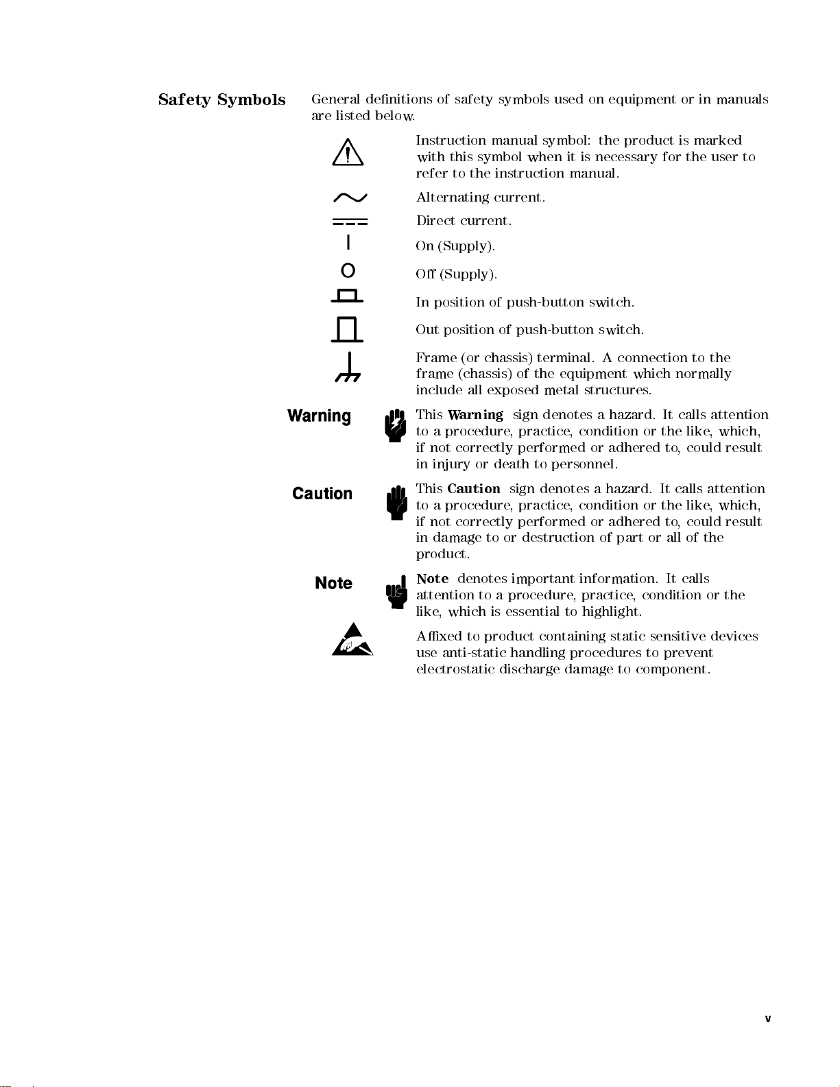
Safety Symbols
General
are
listed below
denitions
.
of
safety symbols
used on
equipment or
in manuals
Instruction
with
this symbol
refer
Alternating
Direct
On
(Supply).
O
(Supply).
In position
Out
position
Frame
frame
include
This
W
to
a
procedure,
if
not
in
injury
This
Caution
to
a
procedure
if
not
in
damage
manual symbol:
to the
instruction manual.
current.
current.
of push-button
(or chassis)
(chassis)
all
exposed
arning
correctly performed
or
death
correctly
to
product.
when it
of
push-button
terminal.
of
the
metal
sign
denotes a
practice,
to
sign
denotes
,
practice
performed
or
destruction
the product
is necessary
switch.
switch.
A
equipment
structures
condition or
or adhered
personnel.
a
hazard.
,
condition
or
of
connection
which
.
hazard. It
the like
It
or
the
adhered
part
or
is marked
for the
to
normally
calls
to,
could result
calls
like
to
,
could
all
of
the
user to
the
attention
,
which,
attention
,
which,
result
Note
denotes
attention
like
Axed
use
to
,
which
to
anti-static
electrostatic
important
a
procedure
is
essential
product
handling
discharge
information.
,
practice
to
highlight.
containing
procedures
damage
,
condition
static
sensitive
to
to
component.
It
calls
prevent
or
the
devices
v
Page 20

4285A
LCR
Precision
Meter
Documentation
Map
The
documentation for
manuals
purpose
.F
ollowing is
.
The
system
basic
the 4285A
a brief
4285A Getting
setup
and
measurements
has been
description of
Started Guide
initial
power-up
and
explains
separated into
each manual
walks
,
shows
you
how
commonly
several
and its
through
to
make
used
features
.
The
4285A
04285-90010)
GPIB
OPERA
provides
programming
TION
MANU
general
information,
AL
(Agilent
information,
and
in
depth
P
art Number
specications
reference
information.
The
4285A
MAINTENANCE
MANU
AL
(Agilent
P
art
Number 04285-90030) explains how to verify conformance
to published specications
.
,
The
4285A SERVICE MANUAL
(Agilent Part Number
04285-90031) explains how to adjust, troubleshoot, and
repair the instrument. (Furnished Option 915 only.)
vi
Page 21

How
T
Manual
o
Use
This
This
is the
Operation Manual
This
manual contains
characteristics
control
reference
commands in
.
specications,
,
installation,
nine chapters
for the
4285A Precision
supplemental performance
conguration, operation,
.Use
this manual
LCR Meter
and remote
for the
function
.
General
Information
Product
DISPLA
MEAS
CA
T
ALOG/SYSTEM
CONFIGURA
Chapter
Chapter
1
2
Installation
Chapter 3
Overview
Chapter
Y
FORMA
Chapter
4
T
5
SETUP
Chapter
6
TION
Chapter
1
provides
characteristics
Chapter
kit
know
Chapter
Chapter
and
menukey
Chapter 5
2
provides
installation,
and
do
3
provides
4
provides
measurement
.
provides
condition setup
Chapter
memory
to
the
6
provides
and
system
4
CA
T
ALOG/SYSTEM
the
,
and
other
unpacking,
and
preparation
before
applying
information
detailed
function,
detailed
,
corresponding
detailed
conguration
5
specications
general
information on
initial
information
A
C
power
including
information
corresponding
information
to
the
information
catalog
menukey
.
, supplemental
the 4285A.
inspection,
rack
necessary
.
a
product
for
the
display
to
the
4
for
the
measurement
4
MEAS
for
of
5
SETUP
the
internal/external
the
4285A, corresponding
performance
mount/handle
for
you
overview
format
DISPLA
Y
FORMA
menukey
to
.
5
T
.
Chapter
Measurement
Chapter
Remote
Chapter
Control
7
Basics
8
9
Command Reference
Appendix A
Manual Changes
Chapter
impedance
Chapter
interface
Chapter
7
provides
theory
8
provides
.
9
provides
the
basic
and
measurement
information
detailed
measurement
techniques
to
control
information for
procedure
.
the
4285A using
each
of
the
with
4285A
the
general
the GPIB
GPIB
commands.
Appendix A contains Manual Changes and provides information for
using this manual with an 4285As manufactured before the printing
date
of the manual.
vii
Page 22

Error
Appendix B
and W
arning
Messages
Appendix
descriptions
B lists
the 4285A's
and solutions
.
error and
warning messages
with brief
Appendix C
Initial
Settings
System
Appendix
Write
Protection
Typeface
Conventions
and
Memory
D
Appendix
status
is
stored
Appendix D
stored data
memory.
Bold
Italics
Computer
C
lists
provides
in
the
the
in
internal
4285A's
4285A's
system
the
procedure
memory
Boldface
F
or
Italic
of
manuals
Italic
when
place
copy
to
type
a
le
Computer
and
initial
memory
type
example:
type
is
type
is
a
name
of
the
lename
a
space
such
as
font
messages
settings
for
write
card
and
is
used
icons
used
and
other
also
or
a
words
means
,
and
file1
is
.
and
.
protecting
internal
when
are
for
emphasis
publications
used
for
variable
in
italics
to
then
.
used
for
functions
EEPROM
a
term
symbols
keyboard
must
.
F
or
type
the
to
type
on-screen
whose
all
of
is
.
and
for
.
entries
be
typed
example:
word
the
prompts
the
dened.
titles
in
copy
name
of
,
Certication
4
HARDKEYS
N
NN
NN
N
N
N
N
SOFTKEYS
5
N
N
N
N
N
N
N
N
N
N
N
N
N
NN
NN
Labeled
are
enclosed
Softkeys
Crystal
keys
in
located
Display
on
the
5
.
4
to
(LCD)
instrument
the
right
are
enclosed
front
of the
panel
Liquid
N
N
in
Agilent Technologies certies that this product met its published
specications at the
Technologies further certies
traceable to the United States
Technology (
nist
facility, or to the calibration
Organization members
time of shipment from the factory
. Agilent
that its calibration measurements are
National Institute of Standards and
), to
the extent allowed by the Institute's calibration
facilities of other International Standards
.
N
N
N
.
viii
Page 23

W
arranty
This
Agilent T
defects
the
listed
manual,
warranty
or
F
or warranty
service
shipping
shall
Buyer
returned
in material
date
of
shipment, except
in \Components
the warranty
period, Agilent
replace products
facility designated
charges to
pay shipping
shall pay
to Agilent
echnologies instrument
and workmanship
that in
not Covered
shall be
for the
Technologies
which prove
service or
repair
,
to be
this
by Agilent
Agilent T
charges to
all shipping
Technologies
echnologies
return the
charges,
from another
product is
for a
period of
the case
by W
of certain
arranty" in
specied period.
will, at
its option,
defective.
product
T
must
echnologies
and
Agilent
product
duties
,
and
country
warranted against
one year
from
components
Chapter 1
of
During the
be
.
Buyer
to
Buyer
taxes
returned
either
T
echnologies
.
for
repair
to
shall
prepay
However
products
.
this
a
,
Limitation
W
arranty
Exclusive
Remedies
of
Agilent
designated
execute
instrument.
of
error
The
improper
software
operation
or
No
specically
tness
The
remedies
Technologies
by Agilent
its
programming
Agilent
the
instrument,
free
.
foregoing
warranty
or
inadequate
or
interfacing,
outside
improper
other
site
preparation
warranty
disclaims
for
a
particular
remedies provided
.
A
gilent
warrants
T
echnologies
that
instruction
T
echnologies does
or
software
shall
,
not
maintenance
unauthorized
of
the
environmental
or
is
expressed
the
implied
purpose
herein are
T
echnologies shall
its
software
for
use
when
not
or
rmware
apply
to
defects
by
Buyer
modication
specications
maintenance
or
implied.
warranties
.
buyer's
not
be
with
property
warrant
will
.
sole
liable
indirect, special, incidental, or consequential
on contract, tort, or any other legal theory
.
and
rmware
an
instrument
installed
that
be
uninterrupted
resulting
,
Buyer-supplied
or
misuse
for
Agilent
of
Technologies
merchantability
and
exclusive
for
any
the
on
operation
from
,
the
product,
direct,
will
that
damages, whether based
or
and
Assistance
Product maintenance agreements and other customer assistance
agreements are available for Agilent T
echnologies products
.
For any assistance, contact your nearest Agilent Technologies Sales
and Service Oce.Addresses are provided at the back of this manual.
ix
Page 24

Page 25

Contents
1.
General
Introduction
Components not
Serial Number
Specications .
Measurement Functions
T
Display
Measurement
Measurement Accuracy Calculation Example . . . . . 1-15
Correction Functions ................ 1-17
Information
.
.
.
.
.
.
.
.
.
.
.
.
.
.
.
.
.
.
Covered
.
.
.
Measurement
Combinations
Mathematical
Equivalent
Ranging .
Trigger
Delay
Time
Measurement
T
est
Cable
Integration
A
veraging
est
Signal
Frequency
Frequency
Signal
Signal
Output
T
j
D
Q
GA
RpAccuracy ...................
RsAccuracy ...................
Basic
N
Cable Length
Temperature F
Example of Ls-Q Accuracy Calculation . . . . . . . 1-15
Zero Open ............ ...... .. 1-17
Zero Short .... ...... ...... .... 1-17
Modes
Normal
Constant
Level
Impedance
est
Signal
Range
Z
j
,
j
Y
j
,
Accuracy
A
ccuracy
Accuracy . . . . . . . . . . .
ccuracy ...........
Accuracy Equations . . . . . . . . . . . . .
Accuracy F
Determine inductance measurement accuracy Ae. 1-15
Determine Q measurement accuracy Qe..... 1-17
P
arameters
of
Functions
Measurement
..
.
.
.
.
.
.
T
erminals
Length
Time
.
.
.
.
.
.
.
A
ccuracy
.
.
.
.
.
.
Level
.
Accuracy
L,
C,
R,
..
.
.
actors . . . . . . . . . . . . . . . .
Factor ...... ...... ...
actor . . . . . . . .
by
W
arranty
.
.
.
.
.
.
.
.
.
.
.
.
.
.
.
.
Measurement
.
.
Circuit
..
.
.
.
.
.
.
.
.
.
.
.
.
.
.
.
.
.
.
.
.
.
.
.
.
.
.
.
.
.
.
.
.
.
.
.
.
.
.
.
.
.
.
.
.
.
.
.
.
.
.
.
.
.
.
.
.
.
.
.
.
.
.
.
.
..
.
.
.
.
..
.
.
.
..
Monitor
.
.
X,
G,
..
.
.
.
.
.
..
and
..
.
.
..
..
B
..
..
.
.
.
.
.
.
.
.
.
.
.
P
arameters
.
.
.
.
.
.
.
.
.
.
.
.
.
.
.
.
.
.
.
.
.
.
.
..
.
.
.
.
.
.
.
.
.
..
..
.
..
.
..
..
.
.
A
ccuracy
.
.
.
.
.
.
.
.
.
.
.
.
.
.
.
.
.
.
.
.
.
.
.
.
.
.
.
.
.
.
.
.
.
.
.
.
.
.
.
.
.
.
.
.
.
.
.
.
.
.
.
.
.
.
.
.
.
.
.
..
..
.
.
.
.
..
.
.
.
.
.
.
.
.
.
.
.
.
.
.
.
.
.
.
.
.
.
.
.
.
.
.
.
.
.
.
.
.
.
.
..
.
.
.
.
.
.
.
.
.
.
.
.
..
.
.
.
.
.
..
..
.
.
.
.
.
.
.
.
.
.
.
.
.
..
..
.
.
..
..
.
.
..
.
.
.
.
.
.
.
.
.
.
.
.
.
.
.
.
.
.
.
.
.
.
.
.
.
.
.
.
.
.........
...... ..
.... ....
..
.
.
..
.
..
.
.
.
.
.
.
.
.
.
.
.
.
..
..
.
.
.
.
.
.
.
.
.
.
.
.
..
.
.
.
.
.
.
.
.
.
.
.
.
.
.
.
.
.
.
.
.
..
. 1-1
.
1-1
. 1-1
1-3
.
1-3
. 1-3
.
1-3
.
1-3
.
1-3
.
1-3
1-3
. 1-3
.
1-4
. 1-4
.
1-4
. 1-4
.
1-4
.
1-4
.
1-4
.
1-4
.
1-4
.
1-4
.
1-4
.
1-5
.
1-5
.
1-6
.
1-6
.
1-9
.
1-9
1-9
1-9
1-10
1-10
1-10
1-10
1-12
1-15
1-15
Contents-1
Page 26

Load
..
..
..
.
.
.
.
.
.
.
.
.
.
.
..
..
..
List
Sweep .
Comparator
Sorting
Sequential
T
olerance Mode
Bin
Count
List
Sweep
Other
Functions
Store/Load
GPIB
GPIB
Self
T
est
Option
Other
Furnished
A
Power
Operating
Dimensions
W
Display
Supplemental P
Stability ...... ....
Temperature Coecient . . . . . . . . .
Settling Time . . . . . . . . . . .
Input Protection
Measurement Time . . . . . . . . . . . . . . . . . 1-23
Option 001 (Internal DC Bias) .. ...... .... 1-23
DC Bias Settling Time . . . . . . . . . . . . . . . . 1-23
001
DC
Bias
DC
Bias
Options
ccessories
T
est
Fixture
DC
Bias
Memory
GPIB
Handler
201
Scanner
301
Requirements
Line
Voltage
Line
Frequency .
P
ower Consumption
T
emperature .
Humidity
Altitude
eight
.
Capable
Number
Frequency (fm)....... ...... .....
Test Signal Level
Measurement Range
Display Time . . . . . . . . . . . . . . . . . . . 1-23
GPIB Data Output Time . . . . . . . . . . . . . . 1-23
.
.
.
.
.
.
.
.
.
.
.
..
Function .
Modes .
mode .
.
.
Comparator
.
.
.
.
.
.
Interface
Level
Monitor
A
Source
Card
Interconnection
Interface
.
Interface
.
Environment .
.
.
of
of
Functions
.
.
.
(Internal
.
ccessories
A
vailable
/
T
est
.
.
.
.
.
.
.
.
.
.
.
.
.
.
.
.
.
.
.
.
.
.
.
Displaying
Display
erformance Characteristics . . . . . .
.
.
.
.
.
.
.
.
.
.
.
.
.
.
.
.
.
.
.
.
.
.
.
.
.
.
.
.
.
.
.
.
.
.
.
.
.
.
.
.
.
.
.
.
.
.
..
.
.
.
.
.
.
.
.
.
.
.
.
.
.
.
.
.
.
.
.
.
.
.
.
.
.
.
.
.
.
.
.
.
.
.
.
.
.
.
.
.
.
.
.
.
.
.
.
.
.
.
.
..
..
..
DC
Bias)
.
.
.
T
erminal
.
.
.
.
Leads
.
.
.
.
.
.
Cables
Connector
..
..
Connector
.
.
..
.
.
.
.
.
..
.
.
.
.
.
.
.
.
.
.
.
.
.
.
.
.
Digits
.................
..... ..... ...... ..
.
.
.
.
.
.
.
.
.
.
.
..
.
.
.
.
.
.
.
.
.
.
.
.
..
.
.
.
.
.
.
.
..
.
.
.
.
.
.
.
.
.
.
.
.
.
.
.
.
.
.
.
..
..
.
.
.
.
.
..
..
.
.
..
for
Mating
.
.
.
.
.
.
.
for
Mating
.
.
.
.
.
.
.
.
.
.
.
.
.
.
.
.
.
.
.
.
.
.
.
.
.
.
.
.
.
.
.
..
.
.
.
.
.
.
..
.
.
.
.
.
.
.
.
.
.
.
.
.
.
.
.
.
.
.
.
.
.
.
.
.
.
.
.
.
.
.
.
.
.
.
.
.
.
.
.
.
.
.
.
.
.
.
.
.
.
.
.
.
.
.
.
.
.
..
..
.
.
.
..
.
............
...... ...
...... ...... ...
..
..
..
.
.
.
..
.
.
.
..
.
.
.
.
.
.
.
.
..
..
..
.
.
.
.
..
.
.
.
..
.
.
..
..
..
..
..
.
.
.
..
..
.
.
.
.
..
..
..
..
..
.
..
..
..
..
..
..
.
.
.
.
.
..
.
.
.
.
.
..
.
.
..
..
..
.
.
.
with Option
.
.
.
.
.
with
Option
.
.
.
.
.
.
.
.
.
.
.
.
.
.
.
.
.
.
.
.
.
.
.
.
.
.
.
.
.
.
.
.
.
.
.
.
..
..
.
.
.
..
.
.
.
..
..
..
..
.
.
..
..
..
..
.
.
.
.
.
......
. 1-17
..
..
..
..
..
. 1-18
..
. 1-18
.
..
.
.
. 1-18
.
..
.
.
.
.
.
.
.
.
.
.
.
.
.
.
.
.
.
.
.
.
.
.
.
.
.
.
.
.
.
..
..
..
. 1-21
. 1-21
..
.
.
. 1-22
1-17
1-18
1-18
1-18
1-18
1-18
1-18
1-18
1-18
1-18
1-18
1-19
1-19
1-20
1-20
1-20
1-20
1-20
1-20
1-21
1-21
1-21
1-21
1-21
1-21
1-21
1-21
1-21
1-21
1-21
1-21
1-21
1-22
1-22
1-22
1-22
1-22
1-22
1-22
Contents-2
Page 27

2.
Installation
Incoming
P
ower Requirements
P
ower Cable
Line
Voltage
Line
Voltage
Inspection .
.
.
.
and
Fuse
Selection
.
.
.
.
.
.
.
.
.
.
.
Selection
.
.
.
.
.
.
.
.
.
.
..
..
. 2-1
.
.
.
.
.
.
.
..
..
..
.
.
.
.
.
.
..
..
..
.
.
.
.
.
.
.
.
.
.
..
.
.
.
.
.
.
.
.
.
.
..
2-3
. 2-3
2-5
. 2-5
Fuse Selection
Operation
Electromagnetic
V
entilation Requirements
Instruction
Rack/Handle
Option
Option
Option
3.
Overview
Introduction .
Product
Front
Environment .
907 Handle
Handle
908 Rack
Rack
Mounting
909
Handle
Introduction
P
anel
1
LINE
2
LCD
3
SOFTKEYs
4
MENU
5
CURSOR
6
ENTRY
7
GPIB
8
5
4
LCL
9
4
TRIGGER
A
MEMORY
B
4
DC
BIAS
C
CONTRAST
for Cleaning
Installation .
and
P
Key
..
Compatibility .
.
Installation .
Kit
Flange
.
.
.
Rack
Flange
Rack
Mounting
.
.
.
.
.
.
.
Description
On/O
anel
Keys
Status
Keys
Keys
5
Key
Card
5
Key
.
.
.
.
.
.
.
.
.
.
.
.
Indicator
.
.
.
.
Slot
.
Control
.
.
.
.
.
.
.
.
.
.
.
..
..
.
.
.
.
.
.
.
Kit
.
.
&
Handle
.
.
.
.
.
.
.
.
.
.
.
.
.
.
.
.
.
.
.
.
.
.
and
.
.
Knob
.
.
.
.
.
.
.
.
..
.
.
.
.
.
.
.
.
.
.
.
.
.
.
.
.
.
.
.
.
.
.
.
.
.
.
.
.
.
Kit
.
.
.
.
.
.
.
.
.
.
.
.
.
.
.
.
.
.
.
.
.
.
.
.
.
.
.
.
.
.
.
.
.
.
.
.
.
.
.
.
.
.
.
.
.
.
.
.
.
.
..
UNLOCK
.
.
.
..
.
.
.
.
.
.
.
.
.
.
.
.
.
.
.
.
.
.
.
.
.
.
.
.
.
.
.
.
.
.
.
.
.
.
.
.
.
.
.
.
.
.
.
.
.
.
.
.
.
.
.
.
.
.
.
.
.
.
.
.
.
.
.
.
.
.
.
.
.
.
.
..
Button .
..
.
..
.
.
.
.
.
.
.
.
.
.
.
.
.
.
.
.
.
.
.
.
.
.
.
.
.
.
.
.
.
.
.
.
.
.
..
..
.
.
.
..
.
.
.
.
.
.
..
..
.
.
.
.
.
.
.
.
.
.
.
.
.
.
.
.
.
.
..
.
.
.
.
.
..
.
.
.
.
.
.
.
.
.
.
.
.
..
.
.
.
..
.
.
..
.
.
..
.
.
.
.
.
.
.
.
.
.
.
.
.
.
.
.
.
.
..
.
.
.
.
. 3-1
.
.
.
.
.
. 3-2
.
. 3-2
.
.
.
.
.
.
.
.
.
. 3-3
..
.
.
. 3-3
.
.
.
.
2-5
2-6
2-6
2-7
2-7
2-7
2-7
2-7
2-7
2-7
2-8
2-8
3-1
3-2
3-2
3-2
3-3
3-3
3-3
3-3
3-3
3-3
D
E
Rear
1GPIB Interface Connector
2Interface Connectors . . . . . . . . . . . . . .
3
4EXT TRIGGER Connector . . . . . .
5
6
7
Display .. ...... ...... ..... .... 3-7
Display Area Denition . . . . . . . . . . . . . . . 3-7
Display Page Format Field . . . . . . . . . . . . . 3-7
System Menu Field . . . . . . . . . . . . . . . . 3-7
Comment Field . . . . . . . . . . . . . . . . . . 3-7
Softkey Area . . . . . . . . . . . . . . . . . . . 3-8
Measurement Data/Conditions Area ........ 3-8
UNKNOWN T
FRAME T
P
anel Description
INT DC BIAS MONITOR Connector
LINE Input Receptacle
LINE VOLTAGE SELECTOR . . . . . . . . . .
erminal
LINE Fuse Holder . . . . . . . . . . . .
erminals .
.
.
.
.
.
.
.
.
.
.....
..
.
.
.
.
.
.
.
.
.
.
.
..
..
.
.
.
.
.
.
..
.
...........
..... ..
......
.......
.
.
..
.
.
Contents-3
3-4
3-4
3-5
3-5
3-5
3-5
3-5
3-6
3-6
3-6
Page 28
Input
Line Area
System
MENU
4
DISPLA
4
MEAS
4
CA
TALOG/SYSTEM
Summary
MEAS
BIN
BIN
LIST
MEAS
CORRECTION
LIMIT
LIST
CA
SYSTEM
CABLE
SELF
Basic
4.
DISPLA
Introduction
MEAS
SYS
N
N
N
N
LOAD
Storing
Loading
N
N
N
N
D.P.
Setting
N
N
N
N
PRINT
Dumping
Printing
NN
N
N
KEY
Locking
BIN
No
COMP
Setting
SYS
Loading
Printing the Measurement Result
Locking Out the Front P
BIN COUNT DISPLA
SYS MENU Field
N
NNNNNNNNNNNNNNNNNNNNNNNNN
COUNT ON
Setting the
Loading or
Printing the Measurement Result ......... 4-17
Locking Out the Front Panel ........... 4-18
LIST SWEEP DISPLAYPage.............. 4-19
MODE Field .................... 4-21
Setting the List Sweep Measurement Mode . . . . . 4-21
SYS MENU Field .................. 4-21
Storing the Control Settings . . . . . . . . . . . . 4-22
Message Area
Keys and
YF
ORMAT
5
SETUP
of
DISPLA
No
.
DISPLA
COUNT
SWEEP
SETUP
T
ABLE
SWEEP
T
ALOG
CONFIG
CORRECTION
TEST
Operation
Y
FORMA
DISPLA
MENU
N
N
N
N
N
N
N
N
N
N
N
N
N
NN
N
N
N
N
N
.
MENU
N
N
N
N
N
N
NN
NN
N
STORE
/
the
NN
N
N
N
N
N
N
N
N
N
N
N
FIX
the
N
N
N
N
N
N
N
N
N
N
N
N
N
DISP
N
N
N
N
N
N
N
N
N
N
N
NN
LOCK
Out
DISPLA
Field
the
Field
N
N
N
the
N
N
N
N
the
out
NN
Field
or
P
ages
(under
.
Y
NN
NN
N
Control
N
N
N
N
N
N
A
Fixed
N
N
N
N
N
N
NN
Softkey
Comparator
Storing
N
NNNNNNNNNNNNNNNNNNNNNNNNN
COUNT OFF
/
Bin Counter ON or OFF
Storing the Control Settings
..
..
.
.
.
.
.
.
.
.
.
.
.
.
.
.
Display
5
..
..
.
5
..
Y
(under
Y
DISPLA
DISPLA
(under
(under
SETUP
SETUP
(under
.
.
T
Menu
.
.
.
P
age
.
N
N
N
Softkeys
Control
N
N
N
N
N
N
N
N
N
D.P.FIX
/
N
N
N
N
N
N
N
N
N
PRINT
/
LCD
the
the
Y
P
age
.
.
.
.
YP
...............
P
age
.
.
.
.
.
.
.
.
.
.
.
.
.
.
.
.
.
.
.
.
.
.
.
.
.
.
.
.
.
.
.
.
.
.
.
.
.
.
.
.
.
.
.
4
DISPLA
Y
F
ORMA
(under
4
CA
(under
4
.
..
..
.
N
N
NN
N
N
N
Decimal
NN
N
N
N
N
N
Screen
Measurement
Front
.
.
the
age ........ ...
4
DISPLA
Y
F
ORMA
Y
(under
Y
(under
4
MEAS
4
MEAS
(under
(under
T
ALOG/SYSTEM
(under
CA
T
ALOG/SYSTEM
.
.
..
..
..
Settings
Settings
N
N
N
N
N
N
N
N
N
N
N
N
N
N
N
N
N
N
N
N
DATA
.
.
P
.
.
.
.
.
..
Control
NNN
4
DISPLA
Y
4
DISPLA
Y
5
)
SETUP
SETUP
4
MEAS
4
MEAS
4
CA
T
ALOG/SYSTEM
4
CA
.
.
.
.
.
.
.
.
.
.
..
.
.
.
.
.
.
.
.
N
Softkeys
P
oint
N
N
N
N
Softkeys
to
the
.
.
.
.
.
..
..
.
.
.
.
.
..
Settings
N
N
N
N
B
N
N
N
N
.
anel
..
Function
anel ...........
Softkeys . . . . . . . . . .
.
5
)
.
SETUP
SETUP
5
)
.
T
ALOG/SYSTEM
5
)
.
.
.
.
.
.
.
.
.
.
.
.
.
..
.
.
.
.
.
.
.
Function
..
Printer
.
.
.
.
.
.
.
.
.
.
.
.
..
..
to
ON
..
...
........
.
.
.
.
.
.
.
.
.
.
.
.
.
.
..
.
.
.
..
..
5
)
.
T
5
)
.
T
F
F
5
ORMA
T
ORMA
T
.
.
.
.
.
.
5
)
.
5
)
.
.
.
.
5
)
.
.
.
.
.
.
.
.
.
.
.
.
.
.
.
.
.
.
.
.
.
.
.
.
.
.
..
.
.
..
.
.
.
.
.
.
.
.
.
.
.
.
..
..
.
.
or
OFF
..
..
..
......
......
.
.
..
..
.
..
..
.
..
..
.
.
.
.
)
.
5
)
.
.
.
.
.
.
.
.
.
.
.
.
5
)
.
.
.
.
.
.
.
.
.
.
.
.
.
.
.
.
.
.
.
.
.
.
.
..
.
.
..
.
.
..
..
.
.
...
...
..
..
..
.
.
.
.
.
.
.
.
.
.
.
.
.
.
.
.
.
.
.
.
.
.
.
.
..
.
.
.
3-8
3-8
3-8
. 3-9
. 3-9
. 3-10
. 3-11
.
3-11
.
3-11
.
3-11
.
3-11
.
3-11
.
3-11
.
3-11
.
3-12
.
3-12
.
3-12
.
3-12
.
3-12
.
3-16
.
4-1
.
4-1
.
4-4
.
4-4
.
4-5
.
4-5
.
4-6
.
4-6
.
4-6
.
4-8
.
4-8
4-9
. 4-9
.
4-10
.
4-12
. 4-12
.
4-13
.
4-13
4-13
4-14
4-15
4-16
4-16
4-16
4-17
Contents-4
Page 29

Loading
Printing
Locking
5.
MEAS SETUP
Introduction
MEAS
FUNC
Choosing
RANGE
N
N
N
N
N
N
AUTO
N
N
N
N
N
N
HOLD
N
N
N
N
N
N
INCR
N
N
N
N
N
N
DECR
Setting
FREQ
N
N
N
N
N
N
INCR
N
N
N
N
N
N
INCR
N
N
N
N
N
N
DECR
N
NN
NN
NN
DECR
N
N
N
N
N
N
kHz
N
N
N
N
N
N
1kHz
Setting
LEVEL
N
N
N
N
N
N
INCR
N
N
N
N
N
NN
mV
Setting
BIAS
N
N
N
N
N
N
INCR
N
N
N
N
N
N
mV
Setting
INTEG
N
N
N
N
N
N
SHORT
NN
NN
NN
MED
NN
NN
N
N
LONG
Setting the
Comment Field .
NNNNNNNNNNN
COM-MENT
NNNNNNNNNNNNN
[!]
NNNNNNNNNNNNNN
CLEAR LINE
NNN
NNNNNNNNNNNNNNNNNNNNNNNNN
ABORT& EXIT
NNNNNNNNNNNNNNNNN
END INPUT
Entering Comments . . . . . . . . . . . . . . . . 5-14
TRIG Field . . . . . . . . . . . . . . . . . . . . . 5-14
NNNNNNNNNNN
INT
NNNNNNNNNNN
MAN
NNNNNNNNNN
N
EXT
Setting the Trigger Mode .. ...... ..... 5-15
the Control
the Measurement
Out the
Menu
..
.
SETUP
N
N
N
N
N
N
N
N
N
N
N
N
N
N
N
NN
N
N
N
N
N
N
N
N
N
NN
NN
NN
N
N
N
N
N
N
N
N
N
N
N
N
NN
N
,
Field
N
N
N
N
N
N
,
NN
NN
NN
N
N
N
N
N
N
P
age
Field
N
N
N
N
N
N
N
N
N
N
NN
NN
NN
Field
N
N
N
N
N
N
N
N
NN
N
N
N
N
N
N
N
MHz
/
N
N
N
N
N
N
N
N
N
N
V
N
N
N
N
N
N
N
V
Field
NN
N
N
N
Softkey
N
N
N
N
NNNNNNNNNNNNNNN
Softkey................... 5-14
Softkey................... 5-14
Softkey................... 5-14
.
the
Measurement
Field
.
.
Softkey
Softkey
NN
NN
NN
*
Softkey
NN
N
N
N
+
Softkey
the
Measurement
.
.
NN
NN
N
*
N
N
N
NN
1Hz
N
N
N
N
N
1Hz
N
N
N
N
N
+
N
N
N
N
N
N
N
N
N
N
1MHz
/
the
Field
N
N
N
N
N
*
N
N
,
the
N
N
N
N
N
*
N
N
,
the
N
N
N
Softkey
Softkey
Softkey ..............
NNNNNNNNNNNNNNNNNN
NNNNNNNNNNNN
.
N
Softkey
N
N
N
N
N
N
N
Softkey
N
N
N
N
N
N
N
Softkey
N
Softkey
N
N
N
N
Softkeys
N
N
N
N
N
N
N
N
N
N
Softkeys
T
est
.
.
N
N
N
N
N
N
N
N
N
NN
N
N
N
N
DECR
/
N
N
N
N
N
NN
N
A
,
and
Oscillator
.
.
.
N
N
N
N
DECR
and
N
N
N
N
N
N
N
N
N
N
N
N
mA
A
,
DC Bias
..
Integration Time . . . . . . . . . . . .
Softkey . .
Softkey . . . .
NNNNNNN
Softkey .......
Settings .
Result
Front
P
anel
.
.
.
.
.
.
.
.
.
.
.
.
.
.
.
.
.
.
.
.
.
.
.
.
.
.
.
.
.
.
.
.
.
.
.
.
.
.
.
Range
.
.
.
.
.
.
.
.
.
.
.
.
..
..
..
.
.
.
.
.
.
.
Frequency
.
..
.
N
N
N
N
N
N
+
Softkeys
N
N
N
N
mA
.
.
N
N
N
N
N
N
N
N
N
N
N
N
N
N
,
and
..
..
..
.
.
.
...... ...... ..... .
Softkey ..............
.
N
NN
N
Softkeys .
Level
.
.
.
N
N
N
N
N
N
N
+
Softkeys
N
N
N
N
N
A
Softkeys
..
..
..
.
..
..
.
.
.
.
.
.
..............
..
.
.
.
.
.
.
.
.
.
.
.
.
.
.
.
.
.
.
.
.
.
.
.
..
.
.
.
.
.
..
..
.
.
.
.
.
..
..
Function
.
.
.
.
.
.
.
.
..
.
.
.
.
.
.
..
.
.
.
.
.
.
..
.
.
.
.
.
.
.
.
.
..
.
.
.
.
.
.
.
.
.
.
.
.
.
..
.
.
.
.
.
.
.
.
.
.
.
..
..
.
..
..
..
..
..
..
.
.
.
.
.
.
.
.
.
.
..
..
.
.
.
..
..
.
.
.
.
.
.
.
.
.
.
.
.
.
.
.
.
.
.
.
.
.
.
.
.
.
.
.
.
.
.
.
.
.
..
.
.
.
.
.
.
.
.
.
.
.
.
.
.
.
..
.
.
.
.
.
.
.
.
.
.
.
.
.
.
.
.
.
.
.
.
.
..
.
.
.
.
.
.
.
.
.
.
.
.
.
.
.
.
.
.
.
.
.
.
.
.
.
.
.
.
.
.
.
.
.
.
.
.
.
.
.
.
.
.
..
..
...... .....
........
.
.
.
..
..
..
.
..
..
..
.
.
..
.
.
.
.
.
.
.
.
.
.
..
.
.
.
.
.
.
....
.
.
.
.
..
..
..
..
.
.
..
..
..
.
.
.
.
.
..
.
.
.
.
.
.
.
.
.
.
..
.
.
.
.
.
.
.
.
.
.
.
.
.
.
..
.
.
.
.
.
.
.
.
..
.
4-22
.
4-22
. 4-24
5-1
5-1
5-4
.
5-4
5-5
5-6
. 5-6
.
5-6
.
5-6
.
5-6
5-7
.
5-7
.
5-7
.
5-7
.
5-7
.
5-7
.
5-8
.
5-8
.
5-9
.
5-9
.
5-9
.
5-9
.
5-10
.
5-11
5-11
.
5-11
.
5-12
.
5-12
.
5-12
. 5-12
5-12
5-13
5-13
5-13
5-13
5-13
5-13
Contents-5
Page 30
ALC
Field .
Setting
MON
Field .
N
NN
NN
N
N
N
N
N
N
N
N
N
N
V
BIAS
NN
N
N
N
N
N
N
N
N
N
N
N
N
N
I
BIAS
Setting the
AVG
Field .
NN
NN
NN
NN
N
N
N
N
N
N
N
INCR
Setting
DELA
Y
Field
N
N
N
N
N
N
N
N
N
N
NN
NN
msec
Setting
Vm/Im
DEV
REF
SYS
CORRECTION
OPEN
SHORT Field . . . . . . . .
FREQ1{7 Fields
Fields
Setting
A/B
N
N
N
N
N
N
N
N
N
N
N
N
N
N
N
1
ABS
N
N
N
N
N
N
N
N
N
N
N
1
%
Softkey
N
N
N
N
N
N
N
N
N
N
N
OFF
Softkey
A/B
N
N
N
N
N
N
N
N
N
N
NN
NN
NN
MEA-SURE
P
erforming the
MENU Field
N
N
N
NN
NN
N
N
N
N
N
N
N
LOAD
/
N
N
N
N
N
N
N
N
N
N
N
N
N
N
N
CLEAR
Resetting
P
age
N
N
N
N
N
N
N
N
N
N
N
N
N
N
NN
PRINT
Dumping
N
N
N
N
N
N
N
N
N
N
N
N
NN
N
SYSTEM
Resetting
Field .
N
NN
NN
NN
N
ON
Softkey .
N
NN
N
N
N
N
N
N
N
N
OFF
Softkey
N
N
N
N
N
N
N
N
N
N
N
N
N
N
N
MEAS
N
N
N
N
N
N
N
N
N
N
NN
NN
NN
ABORT
P
erforming
NNNNNNNN
ON
Softkey .... ....
NNNNNNN
NNNN
OFF
Softkey . . . . . . . . . . . . . . . . . . .
NNNNNNNNNNNNNNNNNNNNN
MEAS SHORT
NNNNNNNNNN
NNNNNNN
ABORT
Performing the SHORT Correction . . . . .
NNNNNNNN
ON
Softkey .... ...... ...... ... 5-34
NNNNNNNNNNN
OFF
Softkey . . . . . . . . . . . . . . . . . . . 5-34
NNNNNNNNNNNNNNNNNNNNNNNNNNNNN
MEAS OPEN
NNNNNNNNNNNNNNNNNNNNNNNNNNNNNNNN
MEAS SHORT
NNNNNNNNNNNNNNNNNNNNNNNNNNNNN
MEAS LOAD
the A
N
NN
NN
Softkey
NN
NN
N
Softkey
N
N
N
N
N
*
and
the
and
the
the
Fields
NN
Softkey
Fields
N
N
N
N
N
N
N
N
N
N
N
N
NN
NN
N
N
N
STORE
N
N
N
N
N
N
N
NN
NN
SETUP
the
.
N
N
N
N
N
N
N
N
N
DISP
the
N
N
N
N
N
N
N
N
N
N
RESET
the
N
NN
NN
NN
NN
N
OPEN
N
Softkey
NNNNNNNNNNN
Softkey
..
..
.
.
.
.
.
.
.
utomatic
.
.
DC Bias
..
NN
NN
NN
NN
DECR
A
veraging
.
.
N
N
N
N
N
N
N
N
N
N
N
sec
Softkeys
Delay
.
.
T
est
Signal
.
.
.
N
Softkey
Deviation Measurement
N
N
N
N
N
N
N
Softkeys .
N
N
N
N
N
N
N
N
N
Softkey
Control
.
.
N
N
N
N
N
N
N
Softkey
MEAS
N
N
N
N
N
N
N
N
N
N
N
N
N
4285A
P
age
..
.
N
N
N
N
Softkey
the
OPEN
Softkey..........
Softkey ........ ...... . 5-34
Softkey............... 5-34
Softkey ........ ...... . 5-35
Level
Control
.
.
.
.
.
.
.
.
.
.
.
.
.
.
.
.
.
.
.
.
.
.
.
.
.
Monitor Mode
.
.
.
.
.
.
.
.
N
N
N
N
N
N
N
N
N
N
N
N
+
Softkeys .
Rate
.
.
.
..
..
Time
.
.
.
.
.
.
.
.
Softkey
.
..
.
.
..................
.........
.
.
.
Level
.
.
.
.
.
.
.
.
.
.
.
.
.
..
.
.
.
.
.
Settings
.
.
.
.
SETUP
.
.
.
.
.
.
.
.
.
.
.
.
.
.
..
Correction
.
.
.
.
.
.
.
.
..
.
.
.
.
.
.
.
.
.
..
.
.
.
.
.
..
.
.
.
.
..
.
.
.
.
.
.
.
.
.
.
.
Monitor
.
.
.
.
.
.
.
.
.
..
.
.
.
.
..
.
.
..
..
.
.
.
.
.
.
.
.
.
.
.
on
the
.
.
..
.
.
.
.
P
age
.
.
.
.
.
..
..
.
.
.
.
.
.
.
.
.
.
.
.
.
.
.
.
..
..
............
...... .....
.
.
.
.
..
..
. 5-16
Function
..
..
.
.
.
.
.
..
..
..
.
.
.
..
.
..
..
.
.
.
.
.
..
.
.
.
.
.
.
Function
.
.
.
..
..
..
.
.
.
..
.
.
.
..
.
.
.
.
.
.
.
.
.
MEAS
.
.
.
.
.
..
.
.
.
..
..
..
.
.
.
.
.
.
.
.
.
.
.
.
.
.
.
.
..
.
.
..
.........
.
..
..
.
.
..
..
..
.
.
.
.
.
.
.
.
.
.
.
..
.
.
.
.
.
..
..
.
.
.
.
..
..
.
.
..
..
..
..
.
.
.
.
.
.
.
.
.
.
.
.
.
.
.
.
.
.
.
.
.
.
.
.
.
.
.
.
.
.
.
SETUP
.
.
.
.
.
.
.
.
..
.
.
.
.
.
.
.
.
.
.
.
.
.
.
.
.
.
.
.
.
.
.
.
..
..
..
..
..
.
.
.
.....
....
.
.
. 5-19
..
. 5-19
.
.
.
. 5-20
.
.
.
.
.
.
.
..
..
.
.
. 5-21
.
.
.
.
.
.
.
.
.
.
.
.
.
.
.
.
.
.
.
.
.
.
.
.
.
.
.
.
.
.
.
.
.
. 5-30
..
.
.
.
.
5-19
5-19
5-19
5-20
5-20
5-20
5-20
5-20
5-21
5-21
5-21
5-22
5-22
5-22
5-22
5-22
5-23
5-23
5-23
5-24
5-24
5-24
5-25
5-25
5-26
5-29
5-30
5-30
5-31
5-31
5-32
5-32
5-32
5-33
5-33
5-33
5-34
Contents-6
Page 31

REF
A/B Fields
P
erforming the
P
erforming the
FUNC
MODE
CABLE Field
SYS MENU
LIMIT
FUNC
MODE Field
NOM
COMP
LOW/HIGH
2nd
A
SYS MENU Field
LIST SWEEP SETUP Page............... 5-59
MODE Field .................... 5-61
List Sweep Parameter Field . . . . . . . . . . . . . 5-62
Sweep Points and Limit Fields . . . . . . . . . . . . 5-63
Field .
Setting
N
N
N
SINGLE
N
N
N
MULTI
Setting the
NN
NN
0m
N
NN
1
N
N
N
2
Selecting the
N
N
NN
PRINT DISP
Printing
N
N
N
SWAP
Swapping the
N
N
N
% TOL
NN
N
ABS
N
N
N
SEQ
Setting
Setting
N
N
N
ON
NN
NN
OFF
Turning
N
N
N
CLEAR
Entering
UX
Setting the A
Loading or Storing the Control Settings
NNNNNNNNNNNNNNNNNNN
N
CANCEL
NNNNNNNNNNNNN
N
CLEAR TABLE
Clearing the Limit T
Printing the LIMIT T
Setting the List Sweep Measurement Mode . . . . . 5-62
Setting the List Sweep Parameter ....... .. 5-62
Setting the Sweep Points and Limits . . . . . . . . 5-64
the Measurement
DUT
Field
N
N
N
N
N
N
N
N
N
N
N
N
N
NN
NN
N
N
N
N
N
N
N
N
N
N
N
N
NN
Softkey
N
N
N
N
N
N
N
Softkey .
N
N
N
N
N
N
N
N
m
Softkey
N
N
N
N
N
N
N
N
m
Softkey
NN
N
N
N
N
N
N
N
N
N
N
N
N
N
T
ABLE
Field
N
N
N
N
N
N
N
N
NN
NN
NN
NN
PARAM
N
NN
NN
N
N
N
N
N
N
N
N
N
Softkey .
N
N
N
N
N
N
N
N
N
N
N
N
N
N
N
N
TOL
N
N
N
N
N
N
N
N
Softkey
the
Field
the
Field
N
NN
NN
Softkey
N
N
N
N
N
N
N
Softkey
N
N
N
N
N
N
N
N
N
N
N
NN
NN
NN
LINE
LOW/HIGH Fields
Field
NNNNNNNNNNNNNNNNNNNNN
..
..
.
.
.
.
.
.
.
.
.
.
.
Spot
OPEN/SHORT
LO
AD
Correction
.
.
.
.
.
.
.
Function
..
.
.
.
.
.
.
.
.
.
.
.
.
.
.
.
Softkey
Correction Mode
Field .
N
N
N
N
N
N
N
N
NN
NN
the
SETUP
N
N
N
N
N
N
N
N
N
N
N
N
N
N
N
Softkey
Comparator
.
Nominal
the
Fields
N
N
N
N
N
N
N
N
N
N
the
.
Softkey ........ ......
.
.
.
.
.
.
.
.
.
.
.
.
.
.
.
.
.
.
.
.
.
.
.
.
.
.
.
.
.
.
.
.
.
.
.
.
.
.
.
Cable Length
..
.
.
N
Softkey .
CORRECTION
P
age
.
.
.
.
N
N
Softkey
..
.
.
.
.
Comparator
N
N
Softkey
LOW/HIGH
.
.
UX BIN to ON or OFF
.
Primary and
.
.
.
.
.
.
.
.
.
.
.
.
.
.
V
.
.
.
..
.
.
.
.
.
.
.
.
.
.
.
.
.... ...... ......
Softkey ..
able..............
ABLE
.
.
..
.
.
.
.
.
.
.
.
.
.
Limit
..
alue
.
..
.
.
.
.
Function
.
.
.
.
Limits
..
.
.
.
.
P
age
..
..
.
Secondary
.
.
.
.
.
.
.
.
.
.
..
..
SETUP P
Correction
.
.
.
.
.
.
.
.
.
.
.
..
of
the
Standard's
.
.
.
.
.
.
..
.
.
.
.
..
..
.
.
.
.
.
.
.
..
.
.
.
.
.
..
..
..
.
.
.
.
.
.
.
.
.
.
.
.
.
.
.
.
.
.
.
.
.
.
.
.
.
.
.
.
.
.
.
.
.
.
.
..
..
..
.
.
.
.
.
.
.
.
.
.
.
.
.
.
.
.
.
.
.
.
.
.
Setup
..
..
.
..
.
.
.
.
.
.
.
.
.
Mode
.
.
.
.
..
..
.
.
.
.
.
.
.
.
.
..
.
............
.
.
.
..
.
.
.
.
.
.
.
.
..
..
..
P
arameters
.
.
.
.
.
.
.
.
.
.
.
.
.
.
.
.
.
.
.
.
.
.
..
.
.
.
..
.
.
.
.
.
.
..
.
.
.
.
.
.
.
.
.
.
.
.
.
.
.
.
.
.
.
.
to
ON
or
OFF
.
.
.
.
.
.
.
.
..
..
.
.
.
.
..
..
..
.
.
.
.
.
.
.
.... ....
......
age ......
..
.
.
.
..
..
..
..
..
.
.
.
.
.
.
..
..
.
.
.
.
.
.
.
.
.
.
.
.
.
.
.
.
.
.
.
.
.
.
.
.
.
.
.
.
.
..
.
.
..
..
.
.
.
.
...
..
.
.
.
. 5-36
..
..
..
. 5-40
.
.
.
.
. 5-41
.
. 5-41
..
. 5-42
.
.
.
.
.
.
.
.
.
.
.
.
.
.
.
.
.
.
.
.
.
.
.
.
.
.
.
.
.
.
.
.
.
..
.
.
..
..
. 5-52
.
.
.
.
..
5-35
5-35
5-38
5-38
5-40
5-40
5-40
5-41
5-42
5-42
5-42
5-42
5-44
5-46
5-46
5-47
5-47
5-50
5-50
5-50
5-50
5-51
5-51
5-51
5-51
5-51
5-51
5-52
5-52
5-54
5-55
5-56
5-56
5-56
5-57
5-57
5-57
5-57
Contents-7
Page 32

SYS
MENU Field
N
N
NN
LOAD
Clear
Printing
6.
CAT
ALOG/SYSTEM Menu
Introduction
CA
TALOG
Media
Record
Record
Comment
SYS
N
NN
CAT
Specifying
Loading
Printing
N
N
PURGE
N
N
CANCEL
Purging the
SYSTEM
BEEPER
Turning
GPIB
Setting
T
ALK
Setting
CONFIG
N
N
I
N
N
Q
N
N
OFF
Conguring
Conguring
Back
HANDLER
Setting
SCANNER
Setting
SYS
Printing the SYSTEM CONFIG P
CABLE CORRECTION P
CABLE CORRECTION MENU Field . . . . . . . . . .
Choosing the 1 m Cable Correction Menu . . . . . .
Choosing the 2 m Cable Correction Menu . . . . . .
NNNNNNNNNNNNNNNNNNNN
REF. 0m
NNNNNNNNN
OPEN
NNNNNNNNNNNNNNNNN
SHORT
NNNNNNNNNNNNNN
LOAD
NNNNNNNNNNNNNN
SAVE
NNNNNNNNNNNNNNNNN
ABORT
Performing the Cable Correction Data Measurement 6-16
NN
NN
NN
NN
N
N
N
N
N
N
N
N
N
N
N
N
N
N
N
N
N
MENU Field
NN
N
N
N
N
N
MENU
N
N
N
NN
N
N
N
N
N
N
BIAS
N
N
ADAPTER
N
NN
N
N
N
N
N
N
N
N
N
N
N
N
STORE
/
Table
the
Page
Monitor Area
Number Monitor
Status Monitor
Monitor Area
N
N
N
N
N
N
N
N
N
N
N
N
N
N
INT
/
or
the
N
NN
NN
N
N
N
Softkey
N
N
N
N
NN
N
N
N
N
N
Softkey
CONFIG
Field
the
ADDRESS
the
ONL
Y
the
Field
N
N
N
N
N
N
N
N
N
N
N
Softkey
N
N
N
N
NN
N
N
N
N
N
N
N
N
N
N
NN
Softkey
to
the
I/F
the
I/F
the
Field
NNN
NNNNN
Softkey
Softkey.................. 6-15
Softkey .................. 6-15
Softkey .................. 6-16
Softkey.................. 6-16
..
..
.
.
.
.
.
.
N
N
N
N
N
N
N
N
Softkey .
Function .
LIST
SWEEP SETUP
..
..
..
..
..
N
NN
NN
NN
NN
N
N
N
N
N
N
N
N
N
N
N
CAT
the
Storing
GPIB
Field
T
N
N
N
N
Handler
Scanner
Softkey . . . . . . . . . .
N
CARD
Media
CA
T
ALOG
.
Unused Record
P
age
.
.
Beeper
Field
A
.
alk-Only
.
.
Softkey
.
..
the
High
the
Precision
Normal
(#201)/(#202)
(#301)
.
..................
.
.
.
.
..
..
..
..
.
.
.
.
.
.
.
.
.
..
.
.
.
.
Area .
Area .
..
..
.
N
N
N
N
N
Softkey
Type
the
Instrument
P
age
.
.
.
.
.
.
.
.
.
.
.
.
.
.
.
ON
or
.
.
.
ddress
.
.
.
.
Mode
.
.
.
.
.
.
.
.
.
.
..
.
DC
LCR
Interface
Field
Interface
.
.
.
.
age ..............
.
.
.
..
.
.
.
.
..
.
.
..
.
..
.
.
.
..
.
.
.
.
.
.
OFF
.
.
.
.
.
.
.
.
.
.
.
.
.
.
.
.
.
.
.
.
.
.
.
Current
Q
Measurement
Measurement
Field
to
.
.
.
to
.
..
.
.
.
.
..
..
Page
.
.
.
.
.
.
.
.
.
.
.
.
.
.
.
.
.
.
.
.
.
..
.
..
Control
..
..
..
.
.
.
.
.
.
.
.
.
.
.
.
.
.
.
.
.
.
.
.
.
.
..
.
.
.
.
.
.
.
.
.
.
.
..
.
.
.
Bias
System
.
.
.
ON
or
.
.
.
ON
or
.
.
.
age .. .....
.
.
.
.
..
.
.
.
.
..
..
.
.
.
..
..
..
.
.
.
.
.
.
.
.
.
.
.
.
.
.
.
.
.
.
.
.
.
.
.
.
.
.
.
.
.
.
.
.
.
.
.
.
.
.
.
.
.
.
.
.
.
.
.
.
..
..
..
Setting
..
.
.
.
.
.
.
.
.
.
.
.
.
.
.
.
.
.
.
.
.
.
.
.
.
.
..
.
.
.
..
..
.
.
.
.
.
.
.
.
.
.
.
.
.
.
.
.
.
.
.
.
.
.
.
.
.
.
.
.
..
..
.
.
.
.
.
.
..
.
.
..
.
.
.
.
.
.
.
.
.
.
.
.
System
Mode
.
.
OFF
.
..
OFF
.
.
...... .
.
.
.
.
.
.
.
.
..
.
..
.
.
.
.
.
.
..
.
. 5-65
. 5-65
.
5-66
. 5-66
.
6-1
.
6-1
.
6-3
.
6-3
.
6-3
.
6-3
.
6-3
.
6-4
.
6-4
. 6-4
.
6-4
.
6-5
.
6-5
.
6-5
. 6-6
6-9
.
6-9
.
6-9
.
6-9
.
6-9
.
6-9
.
6-10
.
6-10
.
6-10
.
6-10
.
6-10
.
6-11
.
6-11
.
6-11
. 6-11
6-12
. 6-12
.
6-12
. 6-12
6-14
6-14
6-14
6-14
6-15
6-15
Contents-8
Page 33

SELF
TEST P
TEST
Memory
P
erforming the
LED
P
erforming the
LCD
P
erforming
Handler
Scanner
P
erforming
Scanner
A
ccessory
Q-A
7.
Measurement
Introduction
Basic
Measurement
Impedance
P
arallel/Series
Selecting
Small
Large
Selecting
Large
Small
T
est
Signal
Oscillator Level
Signal
F
our-Terminal
Measurement
Capacitance
Contact
Measurement
Extending
Guarding
Shielding
Correction
P
erforming
Performing SHORT Correction . . . . . .
Performing LO
Preparing the Standard . . . . . . . . .
Reference V
Using the Pre-Measured Device for the LO
Parasitic Components Related to DUT Connection
Characteristics Example
age .
MENU Field
Card R/W
Display T
Display
dapter
Capacitance
Capacitance
Inductance
Inductance
Level Setting
Inductance
Resistance
T
the
I/F
T
est
I/F
EEPROM
the
I/F
I/O
Control
Buer
Basics
.
.
P
arameters
Circuit
Circuit
Circuit
Level
Pair
Contacts .
to
Ground
Cable
T
est
Leads
for
Low
.
.
.
Functions
OPEN
AD Correction
alues for the LO
..
.
.
.
.
.
.
.
.
.
T
est
.
.
Memory
est
LED
est
LCD
Scanner
T
est
T
.
.
Procedure
Mode
Mode
Mode
.
.
Setting
Measurements .
Conguration
Capacitance
.
.
Correction
Card
.
.
.
.
.
Display
.
.
.
.
.
Display
.
.
.
.
.
R/W
T
I/F
.
.
.
.
I/F
T
est
.
est
.
.
.
.
.
.
..
.
.
.
.
.
.
.
of
Capacitance
.
.
.
.
.
.
.
..
of
Inductance
.
.
.
..
.
.
.
.
.
.
..
.
.
.
.
.
Selection
..
.
.
.
.
.
.
.
.
.
T
ermination
.
.
.
.
.
.
.
.
.
.
.
.
.
.
...............
.
.
.
.
.
.
.
.
.
.
.
.
R/W
T
.
.
.
.
T
est
.
.
.
.
.
T
est
.
.
.
.
.
est
.
.
EEPROM
.
.
.
..
.
.
.
.
.
.
.
.
..
..
.
.
.
.
.
.
.
.
.
.
.
.
.
.
.
.
..
.
..
.
.
..
.
.
.
.
.
.
.
.
.
.
Example
.
.
.
.
.
.
.
.
.
.
.
.
.
.
.
.
.
.
.
.
.
.
.
.
Measurements
.
.
.
.
.
..
..
.
.
.
..
......
AD Standard . . . . . .
est
.
.
.
.
.
.
.
.
.
R/W
.
..
..
.
.
.
.
.
.
..
.
.
.
.
for
.
.
.
.
.
.
.
.
.
.
.
.
.
.
.
.
..
.
.
.
..
..
.
.
.
.
..
.
.
.
.
.
.
.
.
.
.
.
..
.
.
..
..
..
..
..
.
..
..
.
.
.
.
.
.
..
..
.
.
.
.
.
..
..
.
.
.
.
..
.
..
..
.
.
.
.
.
T
est
.
.
..
.
.
..
..
..
..
..
.
.
.
.
.
..
..
.
.
.
.
..
.
.
.
.
.
.
.
.
.
..
..
..
.
.
.
.
.
..
.
.
.
.
.
.
.
.
.
.
.
.
.
.
.
.
.
.
.
.
.
.
.
.
.
.
.
.
.
.
.
.
.
.
.
.
.
.
.
.
.
.
.
.
.
.
..
.
.
.
.
.
.
.
.
.
..
.
.
.
.
..
..
..
..
.
.
.
.
.
......
......
.....
AD ...
...
. 6-19
6-20
. 6-20
.
6-21
. 6-21
.
6-21
. 6-22
6-22
. 6-22
.
6-22
.
6-22
.
6-23
. 6-23
6-23
.
7-1
.
7-1
.
7-1
.
7-4
7-5
. 7-5
.
7-5
.
7-5
.
7-5
.
7-6
.
7-7
.
7-7
.
7-7
.
7-8
.
7-9
.
7-9
. 7-11
.
7-12
7-14
.
7-14
. 7-15
. 7-16
.
7-19
7-19
7-20
7-20
7-20
7-21
7-21
7-22
Contents-9
Page 34

8.
Remote Control
Introduction
General
GPIB
GPIB
GPIB
GPIB
ABORT
CLEAR
DEVICE
LOCAL
LOCAL
REMOTE
SPOLL
SERVICE
TRIGGER
T
est
and
Data
Transfer
ASCII
Binary
Floating
Trigger
Data
Status
Enabling
Operation
Standard
Standard Operation
Standard
Standard
Enabling
Sample
Control
MEAS
CORRECTION
LIMIT
LIST
Data
ASCII
BINARY
..
.
.
Purpose Interface
Connection .
Capability .
Addressing
Bus
Capability
I/O
LOCKOUT/SET
CLEAR
(GTL)
LOCKOUT
.
.
.
REQUEST
Measurement
F
ormat
F
ormat
P
oint
System
Buer
Byte
Programs .
Transfer
.
the
Status
Operation
Operation Status
Event Status
the Event
Settings .
SETUP
T
ABLE
SWEEP
F
ormat
F
.
(IFC)
.
.
.
.
.
.
.
.
(GET)
.
.
.
.
.
.
.
.
F
ormat
.
.
Memory
.
.
..
Status
Register
..
page
page
SETUP
SETUP
Examples
.
.
ormat
(SDC
.
.
.
.
.
.
Bus
(GPIB)
.
.
.
.
.
.
.
.
.
.
.
.
.
.
.
.
.
.
.
.
.
.
.
.
.
.
.
.
.
LOCAL
or
DCL)
.
.
.
.
.
.
(LLO)
.
.
.
.
.
.
Systems
.
.
.
.
.
.
.
.
.
.
..
Byte
Status
Status
Status Register
.
..
.
.
.
.
.
.
.
.
.
.
.
.
.
.
.
.
.
.
.
Language
.
.
.
.
.
.
.
.
.
.
.
.
.
.
.
.
..
.
.
.
..
Group
Condition
Event
Event
Register
.
.
.
.
.
.
.
.
.
.
.
.
page
page
.
.
.
.
..
.
.
..
.
.
.
.
.
..
.
.
.
.
..
.
.
.
.
.
.
.
.
..
.
.
.
.
.
.
.
.
.
.
.
.
.
.
.
.
.
.
.
.
..
..
.
.
.
.
..
.
.
.
.
.
..
.
..
.
.
.
..
.
.
Register
Enable
.
.
.
.
.
.
.
.
.
.
.
.
.
.
.
.
..
.
.
.
..
.
.
.
.
.
.
.
.
.
.
.
.
.
.
.
.
.
.
.
.
.
.
.
.
.
.
.
.
.
..
..
..
.
.
.
.
.
..
(TMSL)
.
.
.
.
..
.
.
.
..
..
.
.
.
.
.
.
.
.
.
.
..
Register
.
.
.
.
.
.
.
.
.
.
.
.
.
.
.
.
.
.
.
.
.
.
.
.
.
.
..
.
.
.
..
.
.
.
.
.
.
.
..
.
..
..
.
.
.
.
.
.
..
.
.
..
..
.
..
..
.
.
.
.
.
..
..
.
.
.
.
.
.
.
.
.
Register
.
.
.
.
.
.
.
.
.
.
.
.
.
.
.
.
.
.
.
..
.
.
..
.
.
..
..
..
..
..
.
.
.
..
..
..
.
..
..
.
.
.
.
.
.
.
.
.
.
..
.
.
.
.
.
.
.
.
.
.
.
.
.
.
.
.
.
.
.
.
..
.
.
.
.
.
.
.
..
.
.
.
.
..
.
..
..
..
.
.
..
.
.
.
.
.
.
.
.
.
.
.
.
.
.
.
.
.
.
.
.
.
.
.
.
.
8-1
.
8-1
8-1
8-3
. 8-4
. 8-4
8-4
.
8-4
.
8-4
. 8-4
8-4
.
8-5
.
8-5
. 8-5
. 8-5
.
8-6
.
8-7
.
8-7
.
8-9
.
8-10
.
8-12
.
8-16
.
8-20
.
8-22
.
8-23
. 8-24
.
8-25
.
8-26
.
8-27
.
8-30
.
8-31
.
8-31
. 8-32
.
8-33
.
8-34
.
8-35
.
8-36
.
8-36
.
8-38
Contents-10
9. Command Reference
Introduction ...........
Notation Conventions and Denitions
Command Structure
Command Abbreviations
Header and P
NR1 .. ...... ...... ...... ....
NR2 .. ...... ...... ...... .... 9-6
NR3 .. ...... ...... ...... .... 9-6
Terminators ........ .... ..... .... 9-7
Program Message Terminators . . . . . . . . . . . . 9-7
Response Message Terminators ........... 9-8
Command Reference ................. 9-9
DISPlaySubsystem .... ...... ...... .. 9-10
arameters . . . . . . . . . . . . . . . .
.................
...............
...... ....
.........
9-1
9-1
9-2
9-4
9-5
9-5
Page 35

:P
AGE
..
..
.
.
.
.
.
.
.
.
.
.
.
..
..
..
..
9-11
:LINE
FREQuency
V
OLT
CURRent
AMPLitude
OUTPut
:Bias
:Bias
BIAS
:ST
:V
:CURRent
FUNCtion
:IMP
:IMP
:IMP
:Source
:Source
:DEV
:DEV
:DEV
LIST
:FREQuency
:V
:CURRent
:BIAS:V
:BIAS:CURRent .
:MODE
:B
APERture
TRIGger
:IMMediate
:SOURce
:DELay
INITiate
[:IMMediate]
:CONTinuous
FETCh?
[:IMP]?
:Source MONitor:V
:Source MONitor:IA
ABORt Subsystem
FORMat Subsystem . . . . . . . . . . .
MEMorySubsystem.. ...... ...... ....
:DIM . . . . . . . . . . . . . . . . . . . . . .
:FILL .......................
:CLEar. ...... ...... ...... .....
:READ? ........ ..... ...... .... 9-56
CORRection Subsystem ................ 9-56
:LENGth..... ..... ...... ...... . 9-58
:METHod ....... ..... ...... .... 9-59
:OPEN . . . . . . . . . . . . . . . . . . . . . . . . 9-60
:OPEN:STATe..... ...... ...... .... 9-61
:SHORt ....................... 9-62
..
.
.
Subsystem .
age
Subsystem
Subsystem .
Subsystem .
Subsystem
MONitor:V
MONitor:CURRent
Subsystem
A
T
e
.
.
.
.
OL
T
age
.
.
.
.
.
Subsystem
edance[:TYPE]
edance:RANGe
edance:RANGe:A
MONitor:V
MONitor:IA
<
n
>
:MODE
<
n
>
:REF
erence
<
n
>
:REF
erence:FILL
Subsystem
.
OL
T
age
.
..
.
.
OL
T
age
..
.
.
AND
<
n
>
.
.
Subsystem .
Subsystem .
..
..
.
.
.
.
.
.
.
.
Subsystem
.
.
.
.
Subsystem
.
.
.
.
.
.
.
.
.
.
.
.
.
.
.
.
.
.
.
.
.
.
.
.
.
.
.
.
.
.
.
.
.
.
.
.
OL
T
age
.
.
.
.
.
.
.
.
.
.
.
.
.
.
.
.
.
.
.
.
.
.
.
.
.
.
.
.
.
..
..
.
.
.
.
.
.
.
.
.
.
.
.
.
.
.
.
.
.
.
.
.
.
.
.
.
.
UTO
.
.
.
A
C
.
.
.
.
.
C
.
.
.
.
.
.
.
.
.
.
.
.
.
.
.
.
.
.
.
.
.
.
..
..
.
.
.
.
..
..
.
..
.
.
.
.
.
.
.
.
.
.
..
.
.
.
.
.
..
.
.
.
.
.
.
.
.
.
.
.
.
.
.
.
.
.
.
.
.
.
.
.
.
.
.
..
.
.
..
.
.
.
.
.
.
.
.
.
.
.
.
.
.
.
.
.
.
.
.
.
.
.
.
.
.
.
.
.
.
.
.
.
.
.
.
.
.
.
.
.
.
.
.
.
.
.
.
.
.
.
.
.
.
.
.
..
.
..
.
.
.
.
.
AC? ......
C?........
...... ....
.
..
..
..
..
.
.
.
.
.
.
.
.
..
.
.
.
.
.
..
..
.
.
.
.
.
.
.
.
.
.
.
.
.
.
.
.
.
.
.
.
.
.
.
..
..
.
.
.
.
.
..
..
.
.
.
.
.
.
.
.
.
.
.
.
.
.
.
..
..
..
..
..
.
.
.
..
.
.
.
.
.
.
.
..
..
..
..
.
.
.
.
..
..
..
.
.
.
.
..
..
..
.
.
.
.
..
..
..
.
.
.
.
.
.
..
..
.
..
..
.
.
.
.
.
.
.
.
.
.
.
.
..
.
.
.
.
.
.
.
.
.
..
..
..
.
.
.
.
.
.
..
..
..
.
.
.
.
.
.
.
.
.
.
.
.
.
.
.
.
.
.
.
.
.
.
.
.
.
.
.
.
.
.
.
.
.
.
.
.
.
.
.
.
.
.
.
.
.
.
.
.
.
.
.
.
.
.
.
.
.
.
.
.
.
.
.
.
.
.
.
.
.
.
.
.
.
.
.
.
.
.
.
.
.
.
.
.
.
.
.
.
.
.
.
.
.
.
.
.
.
.
.
.
.
.
..
..
..
.
.
.
.
.
..
..
.
.
.
.
.
.
.
.
.
.
.
.
.
.
.
.
..
.
.
.
.
.
.
.
..
..
..
..
..
.
.
.
.
.
.
..
.
..........
.........
...... ..
.......
...
..
. 9-13
..
..
.
. 9-16
..
..
.
. 9-19
. 9-20
.
.
.
.
.
.
. 9-24
. 9-25
. 9-26
. 9-27
.
.
.
.
.
.
.
..
.
.
.
.
.
.
.
.
.
.
.
.
.
.
.
.
.
.
.
.
.
.
..
..
..
..
..
..
.
.
. 9-54
9-12
9-14
9-15
9-17
9-18
9-21
9-22
9-23
9-28
9-29
9-30
9-31
9-32
9-33
9-34
9-35
9-36
9-37
9-38
9-39
9-40
9-41
9-42
9-43
9-44
9-45
9-45
9-46
9-47
9-47
9-48
9-49
9-50
9-51
9-52
9-52
9-53
9-55
Contents-11
Page 36

:SHORt:ST
:LO
AD:STA
:LO
AD:TYPE .
:SPOT
:SPOT
:SPOT
:SPOT
:SPOT
:SPOT
:USE
:USE:D
:COLLect[:A
:COLLect:SA
COMP
[:ST
A
:MODE
:TOLerance:NOMinal
:TOLerance:BIN
:SEQuence:BIN
:Secondary
:A
uxiliary
:SW
AP
:BIN:CLEar
:BIN:COUNt[:ST
:BIN:COUNt:D
:BIN:COUNt:CLEar
Mass
:LOAD:ST
:STORe:ST
SYST
ST
ATus
:OPERation[:EVENt]?
:OPERation:CONDition?
:OPERation:ENABle
Common
*CLS
*ESE
*ESR?
*SRE
*STB?
*IDN? .........
*OPC ..........
*WAI ..........
*RST ............
*TST? .. ...... ...... ...... .
*TRG ......................
*LRN?.......................
*OPT?.. ...... ...... .... ......
AT
e .
T
e
.
.
.
<
n
>
:ST
A
T
e
<
n
>
:FREQuency
<
n
>
:OPEN
<
n
>
:SHORt
<
n
>
:LO
AD
<
n
>
:LO
AD:ST
.
.
.
.
.
.
A
T
A?
.
.
CQuire]
VE
.
arator
T
e]
MEMory
em:ERRor? .
Subsystem
.
.
.
.
.
.
.
.
.
<
.
LIMit
BIN
.
.
.
.
.
.
.
.
A
T
A
T
A?
Subsystem
A
T
e
.
.
AT
e
.
Subsystem .
Commands
.
.
.
.
.
.
.
.
.
.
.
.
.
.
.
.
.
.
.
.
.
.
.
.
.
..
.
.
.
.
.
.
.
.
.
.
.
ANdard
.
.
.
.
.
.
.
.
.
.
.
n
>
.
.
.
.
.
.
.
.
.
.
e]
.
.
.
.
.
.
.
.
.
.
.
.
.
.
.
.
..
.
.
.
.
.
.
.
.
.
.
.
..
.
.
.
.
.
..
..
..
..
.
.
.
.
.
.
.
.
..
..
..
.
.
.
.
.
.
..
..
..
..
.
.
.
.
.
.
.
.
.
.
.
..
.
.
.
.
.
.
.
.
.
..
..
.
.
.
.
.
.
.
.
..
..
..
.
.
.
.
.
.
..
..
..
..
.
.
.
.
.
.
.
.
.
..
.
.
.
.
.
.
.
..
..
..
.
.
.
.
.
.
.
.
..
..
..
.
.
.
.
.
.
.
.
.
..
..
.
.
.
.
.
.
.
..
..
..
.
.
.
.
.
.
.
.
.
..
..
.
.
..
..
..
..
.
.
.
.
.
.
.
..
..
..
..
.
.
.
.
.
.
.
.
.
.
.
.
..
.
.
.
.
.
.
..
..
.
.
.
.
.
.
.
.
.
.
.
.
.
.
.
..
.
.
.
.
.
.
.
.
.
.
.
.
.
.
.
.
.
.
..
..
..
.
.
.
.
..
..
..
..
.
.
.
..
..
.
.
.
.
.
.
.
.
.
.
..
..
.
.
.
.
.
.
.
.
..
..
.
.
.
.
.
.
.
.
.
.
.
.
.
.
..
.
.
.
.
.
.
.
.
.
.
..
.
.
.
.
.
.
.
.
.
.
.
.
.
.
.
.
.
.
.
.
.
.
.
.
.
.
.
.
.
.
.
.
.
.
.
.
.
.
.
.
.
.
.
.
.
.
.
.
.
.
.
.
.
.
.
.
.
..
..
.
.
.
.
.
.
.
.
.
..
..
.
.
.
.
.
.
.
.
.
.
.
.
.
.
.
.
.
.
.
.
.
.
.
.
.
.
.
.
.
.
.
.
.
.
.
.
.
.
.
.
.
.
.
.
..
..
.
.
.
.
.
.
.
.
.
.
..
..
.
.
.
.
.
.
.
.
.
.
..
..
..
..
..
..
..
..
.
.
.
.
.
.
.
.
.
.
.
.
..
...... ...... ...
..............
..............
............
..
..
..
..
..
..
..
.
..
.
.
.
..
..
..
.
.
.
.
..
.
.
.
.
.
.
.
.
.
.
.
.
.
.
.
.
.
.
.
.
.
.
.
.
.
.
.
.
.
.
.
.
.
.
.
..
..
..
.
.
.
...
..
..
. 9-65
. 9-66
. 9-67
..
.
.
.
. 9-71
.
.
.
.
.
.
.
.
. 9-75
.
.
.
.
..
.
.
.
.
.
.
.
.
.
.
.
.
.
.
.
.
.
.
.
.
.
. 9-89
.
.
.
.
.
.
.
.
.
.
..
.
. 9-96
.
. 9-98
. 9-99
.
.
.
.
..
. 9-108
9-63
9-64
9-68
9-69
9-70
9-72
9-73
9-74
9-75
9-77
9-78
9-79
9-80
9-81
9-82
9-83
9-84
9-85
9-86
9-87
9-88
9-88
9-90
9-91
9-92
9-93
9-94
9-95
9-97
9-100
9-101
9-102
9-103
9-104
9-105
9-106
9-107
9-110
Contents-12
Page 37

A.
Manual Changes
Introduction
Manual
CHANGE1
B
. Error
Introduction
Error
Messages
Operation
GPIB
Sample
Operation
GPIB
W
arning
C.
Initial
Introduction
D
.
W
rite
Introduction
Write
Protection
Index
..
Changes .
..
and
W
arning
.
Errors
Errors
Program
Errors
Errors
Messages
Settings
.
Protection
.
.
.
.
.
.
.
.
.
.
Messages
.
.
.
.
.
.
.
.
.
.
.
.
.
.
to
Detect
.
.
.
.
.
.
.
.
and
System
.
.
.
.
.
.
.
.
Procedure
.
.
.
.
.
.
.
.
.
.
.
.
.
.
.
.
.
.
.
.
.
.
.
.
.
.
.
the
.
.
.
.
.
.
Memory
.
..
.
.
.
.
.
.
.
.
.
.
.
.
.
.
.
.
Error
.
.
.
.
.
.
..
.
.
.
.
.
.
.
.
.
.
.
.
.
.
.
.
.
.
.
.
.
.
.
.
.
.
.
.
.
.
..
.
..
..
.
.
.
.
.
.
.
..
.
..
.
..
..
..
.
.
.
.
.
.
..
..
..
..
.
.
.
.
..
..
..
..
..
.
.
..
.
.
..
..
..
.
.
.
.
..
..
..
..
..
..
..
..
.
.
..
..
..
.
.
.
.
..
..
. A
. A
..
..
..
..
.
.
.
.
.
.
.
.
.
.
.
..
A-1
-1
-2
B-1
B-1
B-1
B-1
B-1
B-3
B-12
B-14
C-1
D-1
D-1
Contents-13
Page 38

Figures
1-1. Serial
1-2. Eective
1-3. Eective
1-4.
1-5.
1-6. T
1-7.
2-1. P
2-2. Line
2-3. Rack
3-1. Front
3-2.
3-3.
3-4.
3-5.
3-6.
3-7.
4-1.
4-2.
4-3.
4-4.
4-5.
4-6.
4-7.
4-8.
4-9. BIN
4-10. A
4-11. A
4-12. List Sweep Modes
4-13. LIST SWEEP DISPLA
5-1. A
5-2. A
5-3. Measurement Function Display Order
5-4. Eective Measuring Range for Each Measurement
5-5.DCBIASCurrent......... ...... ... 5-11
5-6. COMMENT INPUT Page Layout ........... 5-13
5-7. Required External Trigger Pulse Specication .... 5-15
5-8. Feedback Circuit .................. 5-17
5-9. Available Operating Area For the ALC Function .. . 5-18
5-10. MEAS SETUP Page After Clearing the Setup . . . . . 5-24
Number
V
).
rms
V
).
rms
A
ccuracy
Signal
A
ccuracy
1
V
rms
emperature
Sum
of
the
Charge Time
ower Cable
V
oltage
Mount
P
anel
Rear
P
anel
Display
MENU
Display
CURSOR
Softkey
A
vailable
A
vailable
MEAS
A
vailable
A
vailable
BIN
A
vailable
Available
vailable Fields on the LIST SWEEP DISPLA
vailable Softkeys on the
vailable Fields on the MEAS SETUP
vailable Softkeys on the MEAS SETUP P
Area
keys
P
Selection
DISPLA
No
. DISPLA
COUNT
Range ..................... 5-5
Plate
Measurement
.
.
Measurement Range
..
Equations
Level
Equations
)
.
.
F
actor
DC
Bias
Supplied
Selector
Kits
Overview
Overview
Denition
.
ages
(1/3)
Keys
and
Fields
Softkeys
Y
Fields
Softkeys on
Fields on
Softkeys on
DISPLA
.
Range
.
.
.
.
.
.
.
.
F
,
K
i
1
V
rms
and
.
.
.
.
K
t
Settling
.
.
.
.
.
Installation
.
.
.
.
.
.
.
.
Field
Example
on
the
MEAS
on
the
P
age
Printout
on
the
BIN
the BIN
YP
age Printout
the BIN
the BIN
Y
P
age
...
YP
age Printout
.
.
.
.
.
.
actor
)
.
K
i
.
.
..
.
.
.
.
.
.
.
.
.
.
.
.
.
.
.
.
Operation
MEAS
LIST SWEEP DISPLA
..............
.
.
.
.
.
.
(Oscillator
.
.
.
(Oscillator
.
.
.
,
and
.
.
.
F
actor
(T
.
.
.
.
.
.
Time
and
.
.
.
.
.
.
.
.
.
.
.
.
.
.
.
.
.
.
.
.
.
.
.
.
.
.
.
.
.
DISPLA
DISPLA
Example
No
.
DISPLA
No.
Example .
COUNT DISPLA
COUNT DISPLA
Printout
Level
.
.
.
Level
.
.
.
F
actor
K
osc
.
.
.
est
Signal
.
.
.
.
.
.
DUT
.
.
.
.
.
.
.
.
.
.
.
.
.
.
.
.
.
.
.
.
.
.
.
.
.
.
.
Example
.
.
.
Y
P
age
Y
.
Y
DISPLA
Example
Example .. ..
Page . . . . . .
........
.
.
.
.
.
.
1
.
.
.
.
.
..
>
1
.
.
.
.
.
..
(T
est
.
.
.
.
.
.
Level
>
.
.
.
.
..
.
.
.
.
.
.
(Capacitor)
.
.
.
.
.
.
.
.
.
.
.
.
.
.
.
.
.
.
.
.
.
.
.
.
.
.
.
.
.
.
.
.
.
..
.
.
.
.
.
.
..
.
.
..
.
.
.
.
.
.
..
.
.
.
.
.
..
..
.
..
..
P
age
..
..
..
..
..
Page
..
..
Y
P
age
.
.
.
.
.
.
YP
age
.
YP
age .
.
.
.
YP
age . .
YP
age 4-20
age ....
.
1-1
1-7
1-8
.
1-13
. 1-14
.
1-15
.
1-24
.
2-4
.
2-5
.
2-8
.
3-2
.
3-5
3-7
.
3-9
.
3-13
.
3-16
.
3-16
.
4-2
4-3
4-7
4-11
.
4-12
.
4-14
.
4-15
4-16
.
4-18
4-20
4-21
4-23
5-2
5-3
5-5
Contents-14
Page 39

5-11.
MEAS SETUP
5-12.
Available
5-13.
Available
5-14.
Stray A
5-15.
OPEN/SHORT Correction
5-16.
Residual
5-17.
Spot
5-18.
Display
5-19.
CORRECTION
5-20.
A
5-21.
A
5-22.
Swap
5-23.
T
5-24.
T
5-25.
Limit
5-26.
LIMIT
5-27.
A
5-28.
A
5-29.
SEQ
5-30.
List
5-31.
LIST
6-1.
A
6-2.
A
6-3.
CA
6-4.
A
6-5.
A
6-6. SYSTEM
6-7.
Cable Correction
6-8.
OPEN T
6-9.
SHORT T
6-10.
Available
6-11.
Available
7-1.
Denition
7-2.
V
7-3.
Capacitance
7-4.
Inductance
7-5.
F
7-6.
Measurement
7-7.
Model
7-8. Reducing Capacitance to Ground
7-9. Contact Conguration . . . . . . . .
7-10. T
7-11. T
7-12. Measurement Contacts for T
7-13. Example of DUT Guard Plate Connection
7-14. Guard Shield . . . . . . . . . . . . . . . . . . . .
7-15. Sample Shorting Plate
7-16. Shorting Plate Connection . . . . . . . . . . . . . . 7-20
7-17. Parasitic Impedance Model (Using the 16047A/C/D or
7-18. Typical Characteristics of Components . . . . . . . . 7-23
8-1. GPIB Connector Signal/Pin Conguration . . . . . . . 8-2
8-2. Typical GPIB System Interconnection .. ...... 8-3
8-3. Functional Layers Diagram ............. 8-6
dmittance
Method
OPEN/SHORT/LO
Order
vailable
vailable
P
arameter
olerance
olerance
T
able
T
ABLE
vailable
vailable
mode
Sweep
SWEEP
vailable
vailable
T
ALOG
vailable
vailable
ermination
ector
Representation
our-T
erminal
of
ermination Method
ermination Method (informal method) . . . . . . .
16034E) .. ...... ...... ...... 7-22
Page
Printout Example
Fields
Softkeys
Impedance
Fields
Softkeys
Mode
Limit
Fields
Softkeys
Fields
Softkeys
Fields
Softkeys
CONFIG
ermination (Alternative)
Fields on
Softkeys on
Capacitance
on
the
on
Model
..
.
.
of
the
P
age
Print
on
the
on
Function
and
with
Using
the
SETUP
on
the
on
and
STEP
Settings
SETUP
on
the CA
on
P
age Example
on
the
on
P
age
P
age
(Alternative)
the
of
Impedance
Circuit
Circuit
Mode
Mode
P
air
Measurement
Contacts
CORRECTION
the
CORRECTION
.
.
.
Using
.
.
.
.
.
.
Model
AD
Measurement
the
Sequential
Overlaps
Sequential
P
the
mode
.
.
P
age
the CA
the
the
of
to
.... ....
.
.
Correction
Example
LIMIT
age
LIST
SYSTEM
Example
SELF
T
ABLE
LIMIT
.
.
.
and
Example
SWEEP
LIST
.
.
.
.
.
.
Example
TALOG
TALOG
..
.
SYSTEM
.
.
.
.
TEST
SELF
.
.
.
A
dmittance
Selection
Selection
.
.
.
.
Ground
est Leads Extension
...... ...... ...
P
.
.
.
The
Interpolation
.
.
.
.
.
.
.
Function
.
.
SETUP
T
ABLE
.
.
.
Mode
Gaps
Mode
.
SETUP
SWEEP
.
.
.
.
..
.
P
age
P
age
.
.
.
CONFIG P
CONFIG P
.
.
.
.
.
.
.
.
.
.
.
P
age
TEST
P
.
.
.
.
.
.
Principle
.
..
.
..
.....
.
.
.
.
.
.
.
age
.
.
.
.
.
P
age
.
.
.
.
.
.
.
.
..
.
.
..
..
..
.
.
.
.
.
..
.
.
.
.
.
.
.
.
.
.
.
.
.
.
.
.
.
.
P
age
.
SETUP
.
..
.
.
.
.
.
.
.
SETUP
.
.
..
.
.
.
.
.
.
.
.
.
.
.
.
.
.
.
age
.
.
.
.
.
.
.
.
..
.
.
...... ..
...... ..
P
age
..
..
.
.
.
..
.
.
.
..
.
.
..
..
.
..
..
P
age .
..
P
age
.
.
.
.
.
..
.
.
.
.
..
..
.
.
.
.
.
.
.
.
.
.
.
.
.
.
.
age
.
.
.
age
.
.
.
.
.
.
.
.
.
.
.
.
.
.
.
.
.
.
.
.
.
.
.
.
.
.
.
.
.
.
.
.
.
.
.
.
..
.
.
.
.
.
.
.
.
.
.
.
.
.
.
.
.
.
.
.
.
..
..
..
.
.
.
.
.
.....
...
.... ..
.
5-25
. 5-27
.
5-28
. 5-29
5-30
. 5-32
.
5-34
.
5-39
.
5-43
.
5-45
. 5-46
. 5-47
. 5-48
. 5-49
5-53
. 5-58
5-60
.
5-61
.
5-62
.
5-63
. 5-66
.
6-2
.
6-2
.
6-5
.
6-7
.
6-8
.
6-13
.
6-16
.
6-17
.
6-18
.
6-19
.
6-20
7-2
.
7-4
.
7-5
.
7-6
.
7-8
7-9
.
7-10
7-11
7-12
7-13
. 7-13
7-14
7-14
7-15
7-19
Contents-15
Page 40

8-4.
ASCII F
8-5.
ASCII F
8-6.
BINARY F
8-7.
Binary Data
8-8.
Trigger State
8-9.
INITiate Subsystem
8-10.
Trigger
8-11.
TRIGger:IMMediate
8-12.
*TRG
8-13.
Triggering
8-14.
Buered
8-15.
ASCII
8-16.
BINARY
8-17.
Status
8-18.
Operation
8-19.
Standard
8-20.
MEAS
8-21.
CORRECTION
8-22.
LIMIT
8-23.
LIST
8-24.
Sample
8-25.
Sample
8-26.
Sample
8-27.
Sample
8-28.
Sample
8-29. Sample
9-1.
Command Tree
9-2.
Command Header
9-3.
DISPlay Subsystem
9-4.
OUTPut Subsystem
9-5.
BIAS Subsystem
9-6.
FUNCtion
9-7.
LIST
9-8.
TRIGger
9-9.
INITiate
9-10.
FETCh?
9-11.
MEMory
9-12.
CORRection
9-13. COMP
9-14. Mass MEMory Subsystem Command Tree . . . . .
9-15. ST
D-1. A7 Digital Board Location . . . . . . . .
D-2. Write Protection Switch . . . . . . . . . . . . . . .
ormat 1
ormat
System
or
GET
Data
Description
F
ormat
F
Byte
Event
SETUP
T
ABLE
SWEEP
Program
Program
Program
Program
Program
F
ormat
Program
Subsystem
Subsystem
Subsystem
Subsystem
Subsystem
arator Subsystem Command Tree
ATus Subsystem Command Tree . . . . .
..
2
(List
ormat
ormat
1
F
ormat
Diagram
and
Command
System
Register
Status
.
Subsystem
and
Transfer
.
.
(Buer
(Buer
Register
Status
P
age
page
SETUP
SETUP
(Comparator)
(Buer
(List
(Comparator)
(Buer
.
.
.
(List
Example
and
Command Tree
Command
Subsystem
.
.
.
.
.
.
Sweep)
.
.
F
or
List
.
Commands
Trigger
Command
Sample
Data
Sample
.
.
Memory)
Memory)
.
Register
.
.
.
.
page
.
Memory)
Sweep)
Memory)
.
..
Sweep)
P
arameters
Command Tree
Command Tree
Command
Command
Command
Command
Command
Command
.
.
.
.
.
Sweep
.
.
.
.
Commands
Sample
Transfer
.
.
.
.
.
.
.
.
Structure
.
.
.
..
.
.
.
.
.
.
.
.
.
Using
Using ASCII
Using
.
.
.
Using
.
.
.
Tree
Tree
Tree
Tree
Tree
and
Program
Program
.
Tree
.
.
.
.
.
.
.
.
.
.
.
.
.
..
Measurement
.
.
.
.
.
Trigger
.
.
Program
.
.
.
.
and
.
.
.
..
.
.
.
.
.
.
.
.
.
.
.
.
..
.
.
.
.
.
.
.
.
..
.
.
.
.
.
.
.
.
.
.
.
.
.
.
..
..
ASCII
Using ASCII
Format
BINARY F
Using
BINARY
.
.
.
.
.
BINARY
.
.
.
.
.
.
.
.
.
.
.
.
.
.
.
.
.
.
.
.
.
.
.
.
.
.
.
.
.
.
.
.
.
.
.
.
.
.
.
Tree
.
.
....
..
..
.
..
..
..
..
.
.
.
..
System
.
.
.
.
.
.
.
.
.
.
.
.
.
.
..
..
.
..
..
.
.
..
..
..
.
.
.
.
.
.
..
.
.
.
.
.
.
..
.
.
.
.
..
.
F
ormat
Format
ormat .
.
.
.
.
F
ormat
.
.
.
.
.
.
.
.
.
.
.
.
.
.
.
.
.
.
.
.
.
.
.
.
.
.
.
.
.
.
.
.
.
.
.
.
.
.
.
.
..
..
..
.
.
...
.....
......
..
. 8-8
..
.
.
..
.
.
.
.
.
.
.
.
.
.
.
.
. 8-18
..
..
..
..
.
.
.
.
.
.
.
.
.
.
.
.
.
.
.
.
.
.
.
.
.
.
.
.
.
.
.
.
.
.
.
.
.
.
.
..
.
.
..
8-7
8-9
8-11
8-12
8-12
8-13
8-14
8-14
8-15
8-16
8-18
8-20
8-23
8-28
8-32
8-33
8-34
8-35
8-36
8-37
8-37
8-38
8-39
8-39
9-2
9-5
9-10
9-17
9-20
9-24
9-33
9-42
9-45
9-47
9-52
9-57
9-76
9-88
9-92
D-2
D-3
Contents-16
Page 41

T
ables
1-1. AnEquations .
1-2.
N
A
ccuracy
2-1.
4285A
2-2. Line
2-3. Fuse
2-4. Rack
5-1. Measurement
5-2.
5-3.
5-4.
5-5.
7-1. P
7-2.
8-1.
8-2.
8-3.
8-4.
8-5.
8-6.
8-7.
9-1.
9-2.
A
-1.
A
-2.
V
Selection
Mount
Oscillator
DC
Bias
ALC
Function
Preset
arallel/Series Circuit
Correction
GPIB
Interconnect
GPIB
Interface
Data
F
Status
Standard
Assignments
Standard
Standard
Multiplier
Sux
Manual
Manual
F
Contents
oltage
Level
and
Correction
Functions
ormat
Byte
Assignments
Operation
Operation
Event
Mnemonics
Units
and
Changes
Changes
..
.
actors
Selection
Kits
Function
Resolution
and
.
.
.
.
.
.
.
.
and
Resolution
Setting
Frequency
Cables
Capability
Data
Status
.
.
Status
Status
A
vailable
by
Serial
by
Firmware's V
.
.
.
.
.
.
.
.
.
.
.
.
.
.
.
.
.
.
.
(Option
Range
Model .
.
.
.
.
.
Transfer
.
Condition
.
.
.
Event
Register
.
.
.
Commands
Number
.
.
.
.
.
.
.
.
.
.
.
.
.
.
.
.
.
.
.
.
.
.
.
.
.
.
.
.
.
.
001)
.
.
.
P
oints
.
.
.
.
.
.
.
.
.
.
.
.
.
.
.
Time
.
.
.
.
.
.
.
.
Register
Assignments
.
.
.
.
..
ersion .
.
.
.
.
.
.
.
.
.
.
.
.
.
.
.
.
.
.
.
.
.
.
.
.
.
.
.
.
.
.
.
.
.
.
.
.
.
.
.
.
.
.
.
.
.
.
.
.
.
.
Register
.
.
.
Assignments
.
.
.
.
.
..
.
.
.
.
.
.
.
.
.
.
.
.
.
.
.
.
.
.
.
.
.
.
.
.
.
.
.
.
.
.
.
.
.
.
.
..
.
.
.
.
.
.
.
..
.
.
..
.
.
.
.
.
..
.
..
.
.
.
.
.
.
.
.
.
.
.
.
.
.
.
.
.
.
.
.
.
.
.
.
.
..
.
.
.
.
..
.
.
..
..
.
. 2-5
. 2-5
. 2-7
.
.
.
. 5-9
.
.
.
.
.
.
.
.
..
.
. 8-2
.
.
.
.
.
.
.
.
.
.
.
.
.
.
.
.
.
.
1-11
1-12
2-2
5-4
5-10
5-16
5-29
7-4
7-16
8-3
8-19
8-21
8-24
8-25
8-29
9-6
9-7
A
-1
A
-1
Contents-17
Page 42

Page 43

1
General
Information
Introduction
Components
Covered by
W
arranty
Serial
Number
not
This
chapter
characteristics
The memory
memory card
the
4285A
Agilent
which
to
the
letter
is
the
instrument's
serial
placed
the instrument
describes
,
and
card is
becomes defective
,the
memory card
T
echnologies
stamped
number
on
prex,
between
was
rear
identical instruments;
the instrument.
dierent
for
instruments
numbers
on
The sux,
each
with
the
title
instrument.
the
specications
other
general
not covered
must
uses
a two-section,
the serial
panel.
the
number plate
and
the
two
sections
The
manufactured.
it
changes
however
The
serial
number
page
.
,
supplemental
information
under the
even within
be
paid
for
nine character
rst four
last
ve
digits
identies
The
prex
only
when
,
is
assigned
contents
prex(es)
performance
about the
4285A's
warranty
the warranty
by
the
(
Figure
digits
are
1-1
and
the
the
is
the
same
a
change
sequentially
of
this
manual
listed
under
4285A.
user
.
serial
)
attached
a
letter
sux.
country
for
is
made
the
.
If
period
number
The
where
all
to
and
apply
serial
the
of
are
is
to
Figure 1-1. Serial Number Plate
An instrument manufactured after the
printing of this manual
may have a serial number prex that is not listed on the title
page. This unlisted serial number prex indicates the instrument is
dierent from those described in this manual. The manual for this
new instrument may be accompanied by a yellow Manual Change
supplement or have a dierent manual part number. This sheet
contains \change information" that explains how to adapt the manual
to the newer instrument.
General Information 1-1
Page 44

In
addition to
information
this
manual as
recommends
supplement.
manual's
the
available
an
instrument
Appendix
is
not
contact
printing date
manual's
from
A.
listed
the
change information,
for correcting
current
that you
errors
and
accurate
periodically
The supplement
and
its
title
page
.
Complimentary
Agilent
is
F
or
on
the
nearest
T
echnologies
lower
than
information
title
page
Agilent
T
the supplement
(Errata)
as
request
for
this
part
number
.
If
that
on
the
concerning,
or
in
the
echnologies
in
possible
the
manual
,
copies
the
serial
title
a
Manual
oce
the
,
latest
is
both
of
page
serial
Change
.
may
manual.
Agilent
Manual
identied
of
which
the
supplement
prex
of
or
this
number
supplement,
contain
T
o
keep
T
echnologies
Changes
by
this
appear
number
manual,
prex
on
are
of
see
that
1-2 General Information
Page 45

Specications
Measurement
Functions
The
complete 4285A
specications
the
instrument
meets
the specications
procedures
Number
are the
are covered
04285-90030).
Measurement
specications are
performance standards
is
tested. When
listed in
in
4285A
P
arameters
j
Z
j
:
Absolute value
j
Y
j
:
Absolute value
L
:
Inductance
C
:
Capacitance
R
:
Resistance
G :
Conductance
D :
Dissipation factor
Q
:
Quality
Rs:
Equivalent
Rp:
P
arallel
X
:
Reactance
B
:
Suceptance
:
Phase
angle
listed below
or limits
shipped from
this section.
the factory
The specication
Maintenance Manual
of impedance
of admittance
factor
series
resistance
resistance
. These
against which
, the
(Agilent P
4285A
test
art
Combinations
of
Measurement
j
Z
j
,
j
Y
j
(deg),
(rad)
P
D
,
Q,
arameters
L,
C
,
,GXB
R
R
s
p
RG
Mathematical Functions
The deviation
from
a
programmable
Equivalent
Parallel
and the
Measurement
and
Series
percent
reference
Circuit
of
deviation
value
of
measurement
values
.
Ranging
Auto and Manual (Hold/Up/Down)
Trigger
Internal, External, BUS (GPIB), and Manual.
Delay Time
Programmable delay from the trigger command to the start of the
measurement, 0 to 60.000 s in 1 ms steps.
General Information 1-3
Page 46

Measurement
F
our-terminal pair
T
est Cable
0
m, 1
m,
Length
and
Terminals
2
m
selectable
T
est
Signal
Integration
Short,
P
A
1
Medium,
erformance
veraging
to
256,
programmable
Characteristics"
Frequency
75 kHz
Frequency
6
0.01%
to
30
MHz,
A
Signal Modes
Normal.
Program
terminals when
Constant.
test
(
Signal
dut
)
independent
Level
Maintains
Time
and
Long
100
ccuracy
selected
they
selectable
Hz
resolution.
are
opened
selected
of
changes
for
voltage
or
voltage
(Refer
the
measurement
or
current
shorted,
or
current
in
the
device's
to
\Supplemental
time
at
the
measurement
respectively
at
the
impedance
.)
.
device
under
.
The
following
temperature
Mode Range Setting
V
oltage
Normal 5
Constant
Current
Normal 200A
Constant1100
1
: When the ALC function is set to ON.
For
the temperature range of 0
induced setting error
test
range
1
signal
level
of
23
mV
10 mV
A
C
6
rms
rms
to 20 mA
rms
to
rms
accuracy
C
and
5
to
2
V
to 1
20 mA
Cto
V
the
rms
rms
rms
rms
55
is
specied
test
cable
6f
(8
+
6f
(6
+0.2f
6f
(8+1f
6f
(6+0.2f
C, multiply
for
an
length
A
ccuracy
)%
0.4f
m
)% +
m
)% + 40
m
)%
m
the temperature
listed in Figure 1-6 to the test signal setting
accuracy. When test cable length is 1 m or 2 m, add the following
error due to test cable length.
0:22fm2
L
[%]
Where,
fm: Test frequency [MHz],
ambient
is
0
m.
+
1
mV
1mV
A
+40
A
rms
rms
rms
rms
g
g
g
g
1-4 General Information
Page 47

L
:
Test
cable length
Output Impedance
[m].
The following
is 0
m
:
(25
+
Where
,
fm:
T
The
est
Signal
following
T
ambient
output
)
0
est
:
6
5
f
m
frequency
Level Monitor
test
temperature
impedance
2
10
+
f
3
[MHz]
signal level
range
of 23
is
specied
%
m
monitor accuracy
C
C
and
6
5
for
the
m.
Mode Range Monitor
V
oltage
Current
F
or
the
induced
m
or
2
S
Where
0.01
0.001
temperature
setting
m,
add
the
2
0
:
mon
2
,
mV
rms
A
rms
error
following
2
f
m
{
{20.00
range
listed
2
L
2.000V
mA
of 0
in
Figure
error due
[
V
6f
rms
rms
C
to
55
1-6
to
]
4+0
S
mon
C,
multiply
.When
test
cable
100
the
test
cable
is specied
test cable
A
ccuracy
:
2
f
m
+
S
set
the
temperature
test
cable
length.
length
for an
length is
=
500
g
length
0
[
V
]
is
1
fm: T
L
:
S
mon
S
:
set
F
or
example
T
est
frequency
T
est
signal
Monitor
:
est
T
est
Readout
Setting
,
level
readout
frequency
cable
length
value
value
:
:
value
Cable length :
Ambient temperature :
Then, V
oltage level monitor accuracy V
1Vma=0
Vma=
:52
=
0:024 [V]
0:024
0:5
4:
8 [%]
of
of
1
1
:
500
1
25
4+0
100
[MHz],
[m].
test
test
MHz
V
rms
mV
m
C
:22
signal
signal
rms
1
+
level
level
ma
120:2
100
is
+0
:52
0:2
100
212
1
General Information 1-5
Page 48

Display Range
Measurement
A
ccuracy
The
measurement
linearity
,
repeatability
measurement
conditions
W
arm-up
T
est
F
or
cable
the
are
1
CORRECTION
Parameter Range
j
Z
j
,
R,
j
Y
j
,G,
X
B
0.00001
0.00001
C 0.00001
L 0.001 nH
D 0.000001
Q 0.01 to
1
accuracy
and
accuracy
includes
calibration
is
specied
0
180.000
0
999.999%
satised:
time
:
30
minutes
length
m
or
2
has
:
m
0
m,
cable
been
1
m
(16048A),
length
performed.
to
S
to 99.9999
pF to
to 99.9999
to 9.99999
99999.9
to
to
stability
interpolation
when
all
or
operation
99.9999
999.999
180.000
999.999%
,
temperature
of
the
2
m
(16048D)
(with
M
S
F
H
coecient,
error
.
The
following
16048A/D),
CABLE
OPEN
The
impedance
and
oscillator
500
and
SHORT
optimum
Figure
level
range
.)
to
1-3
Measurement
planes
.
T
est frequency
At
the UNKNOWN
end
of the
T
est frequency
At
the 1-port
should
to
be connected
the end
corrections
measurement
the
eective
.
(F
or
example
is
less
than
accuracy
is
1MHz
terminals on
standard test
1.001MHz
terminal of
to
of
the
standard
have
range
measuring
,
if
the
or
equal 1V
specied
leads
(16048A/D).
the 16085B
the
UNKNOWN
test
been
is
selected
DUT's
at
the
leads
,
the
performed.
by
range
shown
impedance
the
optimum
following
4285A
T
erminal
front
terminals
(16048A/D).
matching
in
Figure
is
range
reference
panel
A
dapter
of
the
the
3
k and
is
or
at
which
4285A
DUT's
1-2
the
the
or
1-6 General Information
Page 49

Figure 1-2.
Eective Measurement Range
(Oscillator Level1V
rms
)
General Information 1-7
Page 50

1-8 General Information
Figure 1-3.
Eective Measurement Range
(Oscillator Level>1V
rms
)
Page 51

j
Z
j
,
j
Y
j
,
L,
C,
R,
X,
G,
and
B
A
ccuracy
j
Z
j
,
j
Y
j
,
Ae=
Where
,
An:
Ac:
Kt:
L,
C,
X,
When
D
R
and G
When
Q
accuracy
only
.
D
A
ccuracy
D
accuracy
Where
,
L,
C,
R,
X,
G,
+
)
6
Basic
T
able
range
Figure
Cable
T
emperature
and
>
x
A
(
A
n
c
accuracy
1-1
.
The
of
equations
1-5
.
(Refer
Length
F
B
accuracies
0.1, multiply
accuracies apply
>
0.1,
D
e
De=
multiply
by
the
is
given
6
x
given
and
B accuracy
2
K
t
equation
applicable
,
A
to
F
actor
(Refer
actor
(Refer
apply when
A
e
when
A
e
equation
as
,
A
e
100
[%]
given
frequency
to
A
1
\Basic
byp1
Q
byp1
above
A
e
from
,
are
16
Accuracy
to \Cable
to \T
emperature F
D
x
2
+D
x
(measured
x
2
+
Q
x
applies
is
given as
the
A
1
range
shown
in
Equations".)
Length F
(measured
for
L, C,
Q value)
for
R
and
to
the
to
A
16
and
impedance
Figure
actor".)
actor".)
D
value)
X, and
G
accuracies
G-B
shown
1-4
or
B
accuracies
0.1.
.
combination
in
0.1.
.
G
Ae:
D
When
Q
Q
Where
Qx: Measured Q value
De: D accuracy
Q accuracy applies when
j
Z
j
,
accuracy
>
D
x
A
ccuracy
accuracy
Qe=
,
Accuracy
accuracy
e=
j
Y
j
,
L, C,
applies
0.1,
multiply
is
Q
e
6
1
is given as
e
1802A
6
2100
R,
X,
when
given as
2
Q
2
x
7
Q
x
.
e
G,
D
D
e
,
D
e
2
D
,
Q
x
,
[
and
B
(measured
x
by
(1
e
2
D
e
deg
]
accuracy
).
+
D
x
<
1.
D
value)
Where,
Ae:jZj,jYj, L, C, R, X, G, and B accuracy
0.1.
General Information 1-9
Page 52

G
Accuracy
G
accuracy
Ge=
Bx=
Where
,
Bx:
Cx:
Lx:
De:
f
G
G
Measured
Measured
Measured
D
:
T
accuracy
accuracy
accuracy
est
combinations
RpA
ccuracy
Rpaccuracy
Rpe=
Where
,
is
G
given as
e
2
6
B
x
2
fC
x
B
value
C
value
L
value
,
frequency
applies
given
R
only
pe
Rpx2
6
by
.
is
given as
Dx7
when
D
=
the
D
e
D
,
[
1
2
f
L
[S],
[F],
[H],
[Hz].
D
x
equation
,
e
e
S
]
x
(measured
above
[]
D
value)
applies to
0.1.
the C
-G
and
p
-G
L
p
Rpx: Measured
Dx:
De:
Rpaccuracy
RsA
Rsaccuracy
Measured D
D
accuracy.
applies
ccuracy
R
Rse=
se
6
Xx=
2
Where
,
R
is
X
x
f
value [],
p
value
when D
given
2
D
=
L
x
,
(measured
x
as
,
[]
e
D
value)
0.1.
1
2
f
C
x
Xx: Measured X value [],
Cx: Measured C value [F],
Lx: Measured L value [H],
De: D accuracy,
f
: Test frequency
Rsaccuracy applies when Dx(measured D value)
[Hz].
0.1.
Basic Accuracy Equations
The basic accuracy Anis calculated from the following procedure.
1-10 General Information
1. Determine Anequation from Figure 1-4 or Figure 1-5. In both
charts, boundary line belongs to the better accuracy area.
Page 53

When
value
determined
When
value
2.
Calculate
included
factors
the oscillator
and
of
K
the oscillator
of
K
in
determined
i
i
A
K
osc
from
from
n
the
value of
A
level
K
1, then
level
>
the Figure
the
formula
equation
n
in
previous
1V
from
osc
round
1V
1-5
is
,
determine A
rms
the Figure
up
K
,
determine A
rms
.
to
be
applied.
shown
step
.
in
osc
to
T
able
1.
n
1-4
n
The
1-2
to
.
to
.
be applied,
If
the
be applied
n
accuracy
Use
and
K
i
and
factor
K
osc
A1=
A2=
A3=
A4=
A5=
A6=
A7=
A8=0
A9=
A10=
A11=
A12=
A13=
A14=
A15=
A16=
j
j
Z
: Absolute
m
fm:
T
est
%
N
+
1
%
N
+
1
%
N
+
1
0
:
3%
+
0
:
18%
0
:
18%
0
:
5%
+
:
18%
%
N
+
2
%
N
+
2
0
:
18%
0
:
3%
+
0
:
18%
0
:
18%
0
:
5%
+
0
:
18%
frequency
0
0
0
0
+
+
0
+
0
0
+
0
+
+
0
+
1
2
f
m
30
1
2
f
m
30
1
2
f
m
5
1
f
m
30
j
j
Z
m
5
k
0
f
m
30
1
f
m
30
j
j
Z
m
50
k
1
2
f
m
30
1
2
f
m
30
0
f
m
5
1
f
m
30
j
j
Z
m
10
k
0
f
m
30
1
f
m
30
j
j
Z
m
100
k
value
2
1
2
1
2
1
2
T
1
1
1
1
1
2
1
1
1
1
2
1
1
2
1
1
in
able
3%
3% +
0
3%
0
:
1
3%
0
:
3%
3%
1
3%
0
:
1
3%
0
:
of
[MHz]
1-1.
50
+
j
Z
j
Z
50
:
1%
+
j
Z
+
500
02%
1
K
3%
+
j
Z
+
5
03%
1
K
100
+
j
Z
j
Z
+
100
0
:
1%
+
j
Z
+
1
02%
1
K
3%
+
j
Z
+
10
03%
1
K
measured
A
2
j
m
2
j
m
j
j
Z
m
500
2
j
m
1
i
j
j
Z
m
5
k
j
m
1
k
1
i
2
j
m
2
j
m
j
Z
m
1
k
2
j
m
k
i
j
j
Z
m
10
k
j
m
1
k
i
Equations
n
0
:
02%
+
0
:
02%
+
2
0
:
02% +
0
:
05%
+
K
osc
2
0
:
02%
0
1
f
m
1
0
30
K
osc
0
:
02%
+
0
:
02%
+
2
j
0
:
02%
0
:
05%
+
2
0
:
02%
0
1
f
m
1
0
30
impedance
+
:
+
:
0
0
0
2%
0
0
+
0
2%
1
f
m
30
1
f
m
30
0
f
m
30
1
f
m
30
0
f
m
10
1
K
1
f
m
30
1
f
m
30
0
f
30
1
f
m
30
0
f
m
10
1
K
in
3
1
1
0
:
1%
1
0
:
05%
1
1
0
:
05%
1
0
:
1%
1
1
0
:
03%
1
K
i
osc
1
0
:
1%
1
0
:
05%
1
m
1
0
1
0
:
1%
1
1
0
:
03%
i
[]
3
3
3
3
:
05%
3
1
K
K
i
osc
1
1
K
K
i
osc
3
1
1
K
K
i
osc
1
1
K
K
i
osc
3
1
1
K
K
i
osc
1
K
i
1
K
i
3
1
K
i
1
K
i
3
1
K
i
General Information 1-11
Page 54

N
Accuracy
Factors
N1and
in
N
the A
2
equations
n
T
able 1-2.
Frequency(f)
75 kHz
200
kHz
3
MHz
5
MHz
f
<
<
<
f
have the
N
A
ccuracy
200
f
3
f
5
30
kHz
MHz
MHz
MHz
following
F
actors
N1N
0.15 0.15
0.08 0.15
0.15 0.38
0.30 0.38
values:
2
1-12 General Information
Page 55

Figure 1-4.
Accuracy Equations,KiFactor,andK
(Test Signal Level1V
rms
osc
)
Factor
General Information 1-13
Page 56

1-14 General Information
Figure 1-5.
Accuracy Equations and KiFactor
(Test Signal Level>1V
rms
)
Page 57

Cable
Length F
actor
A
dd the
accuracy
16048D)
the
following
, when
in
CABLE
cable
the
eld,
OPEN/SHORT correction.
percent.
f
Ac=
Acois
the
Aco=
where
,
fm:
Zm:
Kl:
T
emperature F
Multiply
the
following
range
of
m
+
15
additional
j
j
Z
1
m
1000
Test
Absolute value
Test
actor
the
sum
temperature
C
to
0
55
A
f
m
frequency in
cable length
of
C.
cable
co
error
1
K
the
The
length
length
after
[%]
when
l
[%]
of measured
basic
induced
boundary
set
to
A
c
to
factor
is
performing
When
the
the
impedance
cable
[MHz]
in
[m]
accuracy and
error
belongs
the measurement
1
m
(for
16048A)
the
cable
correction
length
impedance
the cable
,
when
K
t
to
range
the
the
smaller
is
is
in
length factor
or
2m
and
0
m,
above
is
A
c
5
k.
[k]
temperature
multiplier
(for
0
by
.
A
ccuracy
Measurement
Calculation
Example
Example
of
Measurement
Measured
inductance
Figure
-Q
L
s
Conditions
1-6.
A
ccuracy
of
L
x
T
emperature
Calculation
220
nH
F
actor
K
t
DUT:
Measured Q
T
est
Signal
Test Frequency f
Integration Time :
Cable
Operating T
Determine inductance measurement
1. From the \
accuracy Aeis determined as below
2. First of all, to determine the measurement accuracy
Value
Level
Length :
emperature :
Ae=6(
of DUT:
:
: 25.2 MHz
m
30
1
LONG
0m
28
jZj,jYj
An+
,L,
C, R, X, G, and B A
Ac)2K
t
V
rms
C
accuracy A
.
e
ccuracy", measurement
.
Ae, calculate
the impedance value from the DUT's inductance value.Sothe
measurement impedance Zmis :
General Information 1-15
Page 58

Zm=
2
35
f
mLx
[]
Where
fm:
Lx:
3.
Choose
oscillator
measurement.
4.
Find
the
Figure
required.
5.
Find
the
Figure
Interpolation
6.
Mark
the
accuracy
factor
From
T
est
frequency
DUT's
Integration
T
est
signal
Then,
7.
From
the
determined
Then,
A1=
,
T
est
frequency [Hz]
Measured
an
accuracy
level
inductance
is
1
frequency point
1-4
.
Both axis
impedance point
1-4 determined
may be
intersection
equation
.
K
osc
impedance
time
level
=
A
A
n
T
able
as
A
:
f
m
Z
:
:
,
K
i
1
1-1
,
.
A
1
+
f
30
%
N
1
chart
,
V
rms
are in
in step
required.
of
,
integration
n
:
m
=
1,
and
actual
2
1
3%
value
of
the DUT
from
then
of
Figure
f
m
Figure
(25.2
1-4 and
1-4
MHz)
log format.
(35
)
of
Z
above
m
2. Both
two
along
axis
steps and
factor
25.2
MHz
35
LONG
1
V
rms
=
1
K
osc
(Rounded
accuracy equation
50
0
+
j
:
02%
j
Z
m
[H]
Figure 1-5
is
chosen
along
for
the X
this
axis in
Interpolation may
the Y
axis in
are
in
log
format.
determine
,
and
to
30
oscillator
from
be
applied
f
1
0.02).
0
:
1%
K
i
+
.The
be
the
basic
level
is
1
K
i
1
K
osc
1-16 General Information
8.
Determine
From
then,
frequency=25.2 MHz,
N
1
=
N
0.3.
1
from
Table
1-2.
9. Then,
An=0
2:
:
3% +
6 [%]
10. Cable length is 0 m, then
25:2
30
2
1
3% +
Ac=0.
11. Operating temperature is 28C, then
50
0:02% +
j35j
Kt=1 from the Figure 1-6.
12. Therefore, inductance measurement accuracy
25:2
30
Aeis :
10:
1%
111
1
Page 59

Ae=
=
=
6
(
A
6
(
2
6
2
:
6 [%]
+
)
A
2
n
:
6
+
K
c
t
0
)
2
1
Correction
Functions
Determine Q
1. From
the
as below
.
Qe=
2. Determine
step \Determine
[%], then
3.
Therefore
Qe=
=
Zero
Open
measurement accuracy
\Q
A
ccuracy",
Q
6
1
7
D
accuracy
2
x
Q
inductance
Q
measurement
2
D
e
2
D
x
e
for calculating
D
e
measurement
:
A
6
6
is
:
2
Q
x
7
Q
3022
7
30
=
100
0
:
026
2
x
0
e
2
2
D
0
13
e
D
:
026
0
e
:
026
De=
=
Q
e
6
1
6
1
+106
Q
e
.
accuracy
. From
Q
e
accuracy
is determined
Q
e
the
previous
",
Aeis 2.6
A
e
List Sweep
Eliminates measurement
G) of
the
test
xture
errors
due
to
parasitic
stray
admittance
.
Zero Short
Eliminates
(L,
R)
measurement
of
the
test
xture
errors
.
due
to
parasitic
residual
impedances
Load
Improves the measurement accuracy
accurately known (a working standard)
A maximum of 10 frequencies or test signal levels
by using a device which value is
as a reference
.
can be
programmed. Single or sequential test can be performed. When
Option 001 is installed, DC bias voltages can also be programmed.
(C,
General Information 1-17
Page 60

Comparator Function
T
en-bin
decision
sorting
for the
output for
primary measurement
the secondary
measurement parameter
parameter,
and IN/
.
OUT
Other
Functions
Sorting
Sequential
lower
T
olerance Mode
limits
Bin
0
to 999999
List
HIGH/IN/LOW
Modes
mode.
limits.
.
Count
Sweep Comparator
decision output
Store/Load
T
en
instrument
sweep
non-volatile
loaded
programs
memory
from
each
GPIB
All
control
program
data
maximum
GPIB
language
can
format.
of
bus
.
is
settings
be
GPIB
128
Complies
TMSL
Sorting into
.
Sorting
control
,
can
be
.
T
en
settings
into nested
stored
additional
Memory
,
measured
controlled
buer
memory
measurements
with
IEEE-488.1
(T
est
and
unnested bins
bins
for each
,
including
and
loaded
settings
with absolute
with
point
in
comparator
into
can
Card.
values
,
comparator
or
monitored.
can
and
ASCII
store measured
output
packed data
and 488.2.
Measurement Systems
upper and
absolute
the
and
also
limits
and
list
limits
from
be
,
64-bit
values
or
percent
sweep
and
the
stored
list
sweep
binary
over
internal
for
the
The programming
Language).
table
list
and
a
.
Option 001
(Internal DC Bias)
1-18 General Information
GPIB Interface
SH1, AH1,
Self T
T5, L4,
est
Softkey controllable
Functions
SR1,
RL1,
.
Provides
DC1,
a
DT1,
means
C0,
to
conrm
E1
proper
operation.
Adds the variable DC bias voltage function.
DC Bias Level
The following DC bias level accuracy is specied for an ambient
temperature range of 23C65
setting error
listed in Figure 1-6
K
t
C. Multiply the temperature
for the temperature range of 0
induced
to 55C.
C
Page 61

V
oltage
Range
Resolution Setting
A
ccuracy
6
(0.000 to
6
(4.002
6
(8.005
6
(20.01
A
maximum
DC
Bias
DC
bias
connector
The
following
meter
DC
DC
whose
Bias
bias
Output
Monitor
Where
I
is
dut
DC
Bias
DC
bias
to
to
20.000)
to 40.00)
DC
Monitor
voltage
.
monitor
input
V
oltage
voltage
Impedance
A
ccuracy
,
current
Current
current
4.000) V
8.000)
bias
current
T
erminal
or
current
impedance
Monitor
across
:
:
owing
Monitor
through
1
V
V
2
5mV
V
10 mV
of
can
accuracies
is
the
DUT
11
k
6
(0.2%
through
the
mV
mV
100
mA
be
monitored
are
10
2
of
the
DUT
2
6
6
6
6
(0.1%
can
applied
M
1
reading
DUT
10
(0.1% of
(0.1%
of
(0.1%
of
of setting
be
applied
at
the
when
is
used.
+
in
[mA].
(1
V
setting +
setting
setting
rear
the
2
+
0.8
at
100
+
+
+10
to
the
panel
digital
2
mA)
1mV)
2
mV)
5
mV)
mV)
DUT
BNC
volt
)
I
dut
.
mV
Other
Options
Output
Monitor
Option
Option 004
Option
Option 009
Option 109
Option 201
Option 202
Option 301
Option 907
Option 908
Option 909
Impedance
A
ccuracy
002
008
:
10
k
:
A
ccessory
Allows the
Source or
The voltage
4285A
described
6
(1%
of
Control
Interface
4285A to
the 42851A
ratio measurement
is
used
with
in
the
42851A's
reading +
control the
Precision Q
the
42851A
Memory Card
Add
Operation
Manual
(Japanese)
Delete Operation Manual
Delete GPIB Interface
Handler Interface
Handler Interface
Scanner Interface
Front Handle Kit
Rack Mount Kit
Rack Flange and Handle Kit
0.3)
42841A
A
accuracy,
Precision
Operation
mA
dapter
Manual.
Bias
.
when
Q
Current
the
A
dapter
Option 910 Extra Operation Manual
Option 915 Add Service Manual
Option W30 Three Year Customer Return Repair Coverage
Option W32 Three Year Customer Return Calibration Coverage
,
is
General Information 1-19
Page 62

Furnished A
ccessories
Operation
Manual
Agilent
Part
Number 04285-90000
A
ccessories
Available
Maintenance
Memory
P
ower Cord
100
BNC
A
dapter
Card Agilent
Resistor Box
Female-F
Fuse
T
est
Fixture
16034E
16047A
16047C
16047D
16048A
16048D
Manual Agilent
Depends on
is
being used.
Chapter
Agilent P
emale
Agilent
Only
for Option
Agilent
/
T
est
Leads
T
est
Fixture
T
est
Fixture
T
est
Fixture
T
est
Fixture
T
est
Leads
T
est
Leads
Length
Length
Part
Number 04285-90030
Part
Number 04278-89001
the country
Refer to
2in
Page
2-7.
art Number
Part
Number 1250-0080,
201,
P
art Number
for
SMD
or
Chip
for
Axial
or
Radial
for
Axial
or
Radial
for
Axial
or
Radial
1
m
(BNC
2m
(BNC
where the
\Power
Cable
04285-61001
(4 ea).
2110-0046, (2
type
DUT
,
DUT
,
f
DUT
,f
DUT
,
f
connector)
connector)
4285A
"
ea).
f
40
13
40
40
in
MHz
MHz
MHz
MHz
16065A
16334A
16451B
42842C
Agilent
Part
External
V
oltage
Tweezer-type
DUT
,
f
15
MHz
Dielectric T
est
Bias Current
SMD
Test
Fixture (42842C
Bias
T
est
Fixture
Test
Fixture
Fixture
Fixture
Number
42851-61100
DC
Bias Source
42841A
Bias
Current
Source
Memory Card
Agilent P
art
Memory Card, 1 ea.
Number
04278-89001
16470A Memory Card Set, 10 ea.
GPIB Interconnection Cables
10833A GPIB Cable,1m
for
SMD
Option
or Chip
001)
type
1-20 General Information
10833B GPIB Cable,2m
10833C GPIB Cable,4m
Page 63

10833D GPIB
Cable,
0.5m
P
ower
Requirements
Operating
Environment
Handler Interface
Agilent P
art
Number
1251-0084
Scanner
Agilent
Interface
P
art
Number
1251-0142
Line
V
oltage
90
to
132
V
ac
,198
to
Line Frequency
47 to
66
Hz
Power
200 V
T
emperature
0C
Consumption
A
max.
C
to
55
Connector for
AMPHENOL 36-pin
Connector
AMPHENOL
252
V
ac
for
14-pin
Mating with
Connector
Mating
with
Connector
Option
Option
201
301
Dimensions
W
eight
Display
Humidity
95%
R.H.
at
40
C
Altitude
0m
to
2000m
426(W) by
Approximately
LCD dot-matrix display
177(H)
16
by
kg
498(D)
(35.3
.
(mm)
lb
.,
standard)
Capable of Displaying
Measured values
Control settings
Comparator limits and decisions
List sweep tables
Self test message and annunciations
Number of Display Digits
6-digits, maximum display count 999999
General Information 1-21
Page 64

Supplemental
P
erformance
Characteristics
Stability
The
4285A supplemental
These
supplemental performance
but
are
typical
for
the operator
When
the
following
performance characteristics
characteristics are
characteristics included
.
conditions
are
satised,
not specications
as supplemental
are listed
information
below.
T
emperature
Coecient
Settling
Time
Integration
Operating
When
temperature
the
following
Integration
T
est
signal
Operating
temperature
Frequency
<
50
msec
time
P
j
Z
j
,
time
voltage
P
j
Z
j
)
(f
m
.
:
:
arameter
j
Y
j
,
L,
C, R
D
conditions
:
:
:
arameter
,
j
Y
j
,
L,
C,
D
LONG
Constant
23C
1
<
0.01%/day<0.05%/day
<
0.0001/day<0.0005/day
are
operating
C
6
5
MHz
satised,
LONG
20
mV
rms
R
23
<
0.004%/
<
0.00004/
C
1
6
5
MHz
C
C
<
C
<
temperature
30
MHz
30
MHz
0.05%/
0.0005/
of
C
C
Input Protection
1-22 General Information
T
est
Signal
<
100
Measurement
<
50 msec
Level
msec
.
./range shift
Range
Internal circuit protection, when a charged capacitor is connected to
the UNKNOWN terminals
.
The maximum capacitor voltage is:
r
=
1
[
V
C
]
V
max
Where,
V
:
max
C
: Capacitance value in Farads.
200 V,
Page 65

Measurement Time
Typical
the
measurement
Handler Interface
times
. (EOM:
from the
End of
trigger to
the output
Measurement)
of EOM
at
In
the
following
300
ms
,
is
added
T
est
signal
voltage
Measurement
T
est
signal
Display
Display
MEAS
BIN
No
BIN
COUNT DISPLA
GPIB
Internal
data
current:
Time
time
DISPLA
.
DISPLA
Data Output
GPIB
output
Integration
MEDIUM 65
condition.
to
the
measurement
:
range
:
for
each
display
Y
page
Y
page
Y
page
Time
data processing
on
GPIB lines
Measurement
Time
Time
SHORT 30
LONG 200
An
0.51
0
22
additional
V
{
2
Range
mA
format is
measurement
time
.
V
rms
given as
approx.
approx.
approx.
time
from
EOM
(excluding
display
ms
ms
ms
8
ms
5ms
0.5
output
time).
ms
time
,
approx.
to
measurement
Option
DC
Bias
001
(Internal
DC
Settling
Bias)
Time
Approx.
Maximum
performed
When
DC
settling
Sum
shown
time
of DC
in the
10
ms
DC
bias
current
is
100
mA.
bias
is
set
does
not include
bias settling
following
to
ON,
time plus
gure
when
add
the DUT
.
the normal
5
ms
to
the measurement
charge time
DUT (capacitor)
measurement can
time.
.
charge time
be
This
is
General Information 1-23
Page 66

Sum
This
Cet
of
ISM
device
appareil
the
DC
ISM
Bias
complies
est
conforme
Figure
Settling
with
1-7.
Time
Time
Canadian
a
la
norme
and
DUT
ICES-001.
NMB-001
(Capacitor) Charge
du
Canada.
1-24 General Information
Page 67

Installation
2
Incoming
Inspection
W
arning
This chapter
incoming
chapter
provides the
inspection
are:
Incoming Inspection
Power
Line
Operation
requirements
V
oltage
and
Environment
Electromagnetic
Ventilation
Instruction
Rack/Handle
T
o
avoid
when
there
outer
enclosure
Requirements
for
Installation
hazardous
are
and
setting
Fuse
Selection
Compatibility
Cleaning
electrical
signs
of
shipping
(for
example
information
up
the
shock,
damage
,
covers
necessary
4285A
.
do
not
to
,
panel,
for
The
turn
any
or
performing
main
topics
on the
portion
display)
an
in
4285A
of
the
this
Inspect
or
of
has
the
the
shipping
cushioning material
the shipment
been checked
shipment
have been
mechanically and
should
container
is damaged,
checked for
be
as
listed
for
in
damage
.
If
the
it should
be kept
completeness and
electrically.
T
able
2-1
.
If the
shipping container
until
the
contents
the
4285A
The contents
contents
of
are
incomplete, if there is mechanical damage or defect, or if the analyzer
does not pass
Technologies oce
cushioning material shows signs
well as the Agilent T
the power-on selftests
, notify the nearest Agilent
. If the shipping container is damaged, or the
of unusual stress
echnologies oce
. Keep the shipping materials
, notify the carrier as
for the carrier's inspection.
Installation 2-1
Page 68

T
able 2-1.
4285A Contents
Description Qty.Agilent
P
art
Number
4285A
Power
100
BNC
Operation
Maintenance
Option
1
cable
Resister
F
emale-F
Manual
004 Memory
Box
emale
Manual
A
dapter
Card
1 |
1 04285-61001
4 1250-0080
1 04285-90010
1 04285-90030
Memory Card 1 04278-89001
Option
201
Fuse
Fuse 2 2110-0046
Option
Handle
Option 908
Rack Flange
Option
Rack
1
P
ower
Cable
907
kit
909
Flange
Cable
".
Handle
Kit
Rack Flange
Kit
Rack
Flange
and
Handle
depends
on
Kit
&
Kit
where
Handle
Kit
the
instrument
1 5061-9690
1 5061-9678
1 5061-9684
is
used,
see
\P
ower
2-2 Installation
Page 69

P
ower
Requirements
The
4285A requires
V
oltage :
90 to
the following
132 V
ac,
198 to
power source:
252 V
ac
P
W
arning
ower
Cable
Frequency
P
ower :
In
accordance
is
equipped
appropriate
frame
.
The
type of
the
country of
of
the power
F
or
protection
must
not
The
power
protective
:47
to 66
200 V
A maximum
with
international
with
a
three-wire
ac power
power cable
destination. Refer
cables available
from
be
defeated.
plug
must
earth
ground
Hz
power cable
outlet, this
shipped with
.
electrical
be
plugged
connection.
safety
standards,
. When
cable grounds
each instrument
to Figure
shock,
into
2-1 for
the power
an
outlet
this instrument
connected to
the
instrument
depends
the
part
cable ground
that
provides
an
on
numbers
a
Installation 2-3
Page 70

2-4 Installation
Figure 2-1. Power Cable Supplied
Page 71

Line
Fuse
V
oltage
Selection
and
Figure
on
2-2 illustrates
the instrument's
the line
rear panel.
voltage selection
switch and
fuseholder
Line
Caution
V
oltage
Selection
Fuse Selection
Before
that
the
Switch
Select
Select
the
fuse
listed,
connecting
correct
is
correctly
the
proper
proper
along
are
fuse
printed
with
Figure
the
instrument
fuse
has
set.
voltage
T
able
V
oltage
Selector
115
230
according
under
the
fuse's
T
able
Operating
Voltage
115 V
230 V
2-2.
Line
V
oltage Selector
to
the
power
been
selector
2-2.
installed
Line
and
according
V
oltage
the
to the
Selection
Line
V
oltage
90{132
V
V
the
198{252
to
the T
fuseholder
Agilent
2-3.
part
Fuse
V
,
47{66
V
, 47{66
able 2-3
on the
number,
Selection
. Current
Fuse
Rating/Type
3A 250V
Part Number
ac
UL/CSA type 2110-0381
Time Delay
2A 250V
ac
UL/CSA type 2110-0303
Time Delay
source
Line
Table
Hz
Hz
rear panel,
in T
Fuse
,
make
V
oltage
2-2
ratings for
able 2-3
sure
Selection
.
and are
.
If you need this fuse,contact your nearest Agilent Technologies Sales
and Service Oce.
To remove the fuse, turn the fuse holder counterclockwise until the
fuse pops out.
Installation 2-5
Page 72

Caution
Operation
Environment
Note
Electromagnetic
Compatibility
Use
the
proper
the
required
DO
NOT
use
by-pass
The
conditions
avoid
T
emperature:
a
blown
4285A
,
obstructing
Humidity:
The
4285A
cause
condensation
This
product
the
Electromagnetic
T
o
use
a
properly
those
recommended
T
est)
to
connect
peripherals
,
requirements
fuse
current
a
mended
fuse
must
be
operated
and
sucient
the
C
0
less
must
be
protected
within
has
been
shielded
each
equipments
.
for
the
line
rating
.
fuse
Find
and
or
short-circuit the
out
what
under
space
must
air
ow
of
C
to
55
than
95%
RH
from
the
instrument.
designed
Compatibility
cable
in
the
General
of
the
ports
or
devices
voltage selected.
of
the
specied type
the
at
caused
within
be
cooling
40
kept
C
the fuse
the
behind
fans
temperature
and
tested
(EMC)
or
shielded
to
the
Directive
coaxial
Information
to
their
respective
may
ensure
Use only
as replacements
fuse-holder in
to blow!
following
environment
the
4285A
.
extremes
requirements
89/336/EEC.
cable
(such
and
the
P
erformance
controllers
to
meet
the
fuses with
order to
to
which
could
of
as
,
.
2-6 Installation
Page 73

V
entilation
Requirements
Instruction
for
Cleaning
Rack/Handle
Installation
T
o ensure
clearance
To
prevent electrical
the receptacle
dipped in
adequate ventilation,
around the
before cleaning.
water to
4285A internally
The
4285A
measurement
4285A
can
system.
.
be
.
shock,
clean
rack
4285A.
the
mounted
Figure
make sure
disconnect
Use
a
casing.
Do
and
2-3
shows
the
dry
not
used
how
that there
4285A
cloth
or
attempt
as
a
component
to
rack
is adequate
power
a
cloth
to
clean
mount
cable
slightly
the
in
a
the
from
Option
907
Handle
Kit
Option 908 Rack
Flange Kit
Table
Option Description Kit
907 Handle
908 Rack
909 Rack
Option
necessary
Handle
1.
2.
3. Attach
907
Installation
Remove
front
sides
Attach
hardware
the front
the trim
is
a
the adhesive-backed
of the
Flange
Flange
Handle
to
4285A.
handles 3
strips 4
2-4.
Kit
Kit
&
Handle Kit
kit
containing
attach
to the
Rack
them
to
trim strips
to the
handles.
Mount
Agilent
Agilent
Agilent
a
the
Kits
P
P
P
pair
of
instrument.
1 from
sides using
P
art
Number
art Number
art
Number
art
Number 5061-9684
handles
the
the
screws
5061-9690
5061-9678
and
left
and
the
provided.
right
Option 908 is a rack mount kit containing a pair of anges and the
necessary hardware to mount them to the instrument in an equipment
rack with 482.6 mm (19 inches) horizontal spacing.
Rack Mounting
1. Remove the adhesive-backed trim strips 1 from the left and right
front sides of the 4285A.
2. Attach the rack mount ange 2 to the left and right front sides of
the 4285A using the screws provided.
3. Remove all four feet (lift bar on the inner side of the foot, and
slide the foot toward the bar).
Installation 2-7
Page 74

Option 909
Flange
& Handle
Rack
Kit
Option
909 is
necessary
handles
spacing.
a rack
hardware to
attached, in
mount kit
containing a
mount them
an equipment
to an
instrument which
rack with
pair of
482.6 mm
anges and
has
(19 inches)
the
Handle
1.
Remove the
front
2.
Attach the
on
the left
provided.
3.
Remove all
slide
and Rack
adhesive-backed trim
sides of
front handle
and right
four feet
the foot
Mounting
the 4285A
front sides
(lift
toward the
.
3and
bar
bar).
on
the
strips 1
rack
of
the
the
mount
4285A
inner
from
side
the
ange
using
of
the
left
5
together
the
foot,
and
right
screws
and
2-8 Installation
Figure 2-3. Rack Mount Kits Installation
Page 75

Overview
Introduction
This
chapter
operating
Before
and
using
eciently
provides
the
Agilent
the 4285A
learn the
the
information
T
echnologies
, read
through this
4285A's
you
Model
operation.
will need
to know
4285A Precision
chapter
so
you
before
LCR Meter
can
quickly
3
.
Product
Introduction
The 4285A
components
for
evaluating
over
a
levels
The
4285A
(L,
C),
resolution
can output
into
a maximum
scanner
component
component
is
a
general
,
quality
LCR
wide
range
of
(5
mV
to
2V
rms
measures
6
0.001
(D)
with
is
0.000001).
comparison/decision
of
interface options
handler
, scanner
testing,
purpose
control,
and laboratory
components
frequencies
,
200
A
L-Q
and
six digit
With
its
ten
bins
.
By
,
the
,
and
sorting, and
LCR
meter
,
materials
(75
kHz
to 20
mA
C-D
with a
resolution (the
built-in
results
using
the
4285A
can
system
quality
for
incoming
use
.
The
,
and
semiconductor
to
30
MHz)
).
rms
basic accuracy
dissipation
comparator
for
sorting
handler
easily
interface
be
controller
control
data
inspection
4285A
and
test signal
of
6
factor
,
the 4285A
components
and
combined
to
fully
automate
acquisition
is
used
devices
0.1%
with
and
of
a
processing.
The
4285A's
frequencies
,
list
test
sweep
signal
function
levels
,
permits
or
bias
level
entry
points
of
up
to
to
be
ten
automatically
measured.
The
GPIB
used
to
new
components
interface
build
an
automatic
and
is
a
standard
materials
test
interface
system
,
and
to
to
fully
on
the
4285A
completely
automate
and
can
characterize
production
be
line
testing.
The 4285A with an Option 002 accessory control interface
bias current source
, and an 42842C bias current test xture can apply
a 0 to 10A DC current bias to the device under test (
, an 42841A
dut
). So
,high
current biased impedance measurement of coils and transformers can
be performed easily
, quickly
, and safely
.
The 4285A with Option 002 accessory control interface and the
42851A
Q adapter realize stable high Q measurement using the
resonant measurement method and an automated tuning operation.
Overview 3-1
Page 76

Front P
anel
Description
Figure
front
3-1 shows
panel.
the brief
description of
each key
on the
4285A's
Figure
1
Power
applied to
are applied
2
The Liquid Crystal Display (
conditions, softkey labels
LINE
on/o
LCD
3-1.
Front
P
On/O
switch.
the instrument.
P
anel
to the
instrument.
anel
Overview
In
the
ON
position
In
the
OFF
position
lcd
) displays measurement results
, and other information.
all
operating
NO
operating
voltages
3SOFTKEYs
Five softkeys are used
Each softkey has a softkey
to select control and parameter functions
label along its left side
.
4MENU Keys
Menu selection keys. There are three menu keys,
4
MEAS SETUP
5
,and
4
CATALOG/SYSTEM
5
. The menu keys are used to
4
DISPLAYFORMAT
access the corresponding selection of instrument functions.
are
voltages
, test
.
5
,
3-2 Overview
Page 77

5
CURSOR
The
CURSOR arrow
eld
to eld
eld
the eld
The
cursor can
monitor
6
ENTRY
The
ENTRY
ENTRY
sign
5
4
,
-
input
data
line
from
character
7
GPIB
The
GPIB
L
TN
(listen),
are
used
controller
8
4
LCL
Local
5
the
The
from
Lockout
Keys
on
changes
area.
K
eys
keys
keys
are
4
ENTER
and
the
bottom
of
the
Status
status
and
to
show
via
GPIB
K
ey
(LCL)
remote
command
only front-panel
state
.
the
LCD
only
are
composed
5
,
and
enters
input
Indicator
indicators
SRQ
the
.
key
(computer
has
key
keys
are
display
to
an
be
moved
used
to
4
BA
CK
SP
the
displayed
of
the
value
consist
(service
4285's
returns
been
activated
used
to
page
inverse
to
a
eld,
enter
numeric
of
the
digits
5
keys
A
CE
LCD
screen).
.
of
request)
GPIB
status
the 4285A
controlled)
invoked
while
move
.
When
video
4
0
.
4
ENTER
value
the
indicators
to local
operation
from
the
the
the
image
it
can't
data
5
to
on
the
4
BA
CK
RMT
when
the
4285A
eld
select
cursor
of
the
be
moved
into
the
5
,
a
4
period
9
5
terminates
Input
5
A
CE
deletes
SP
(remote),
.
These
it
is
interfaced to
(front-panel)
state
unless a
computer.
is
in
the
cursor
is
moved
original
into
4285A
5
,
4
.
numeric
line
(second
TLK
(talk),
indicators
operation
5
4
LCL
REMOTE
eld.
a
.
a
minus
one
Local
is
from
to a
The
last
a
the
9
4
TRIGGER
This
key is
Manual
A
MEMORY
The
MEMORY
UNLOCK
B
4
DC
4
DC BIAS
is a toggle type switch, and the DC BIAS ON/OFF LED indicator
located above
to the DUT
5
Key
used to
Trigger
button
5
K
BIAS
5
is used to enable or to disable the DC bias
mode
Card
card
is
ey
4
DC BIAS
manually
trigger
the
4285A
when
it
is
.
Slot
and
slot
used
is
where
to
UNLOCK
eject
you
a
memory
insert
Button
the
memory
card.
output.
5
. There are two ways to apply the DC bias
. One is Option 001 DC bias option and the other is the
set
cards
to
the
.
The
4
DC BIAS
is
42841A Bias Current Source combined with the 42842C Bias Current
Test Fixture
simply the DC bias output turns ON or OFF
must be set in the
. Either one can be selected in the
, and the DC bias value
BIAS
eld.
CONFIG
eld.
4
DC BIAS
CCONTRAST Control Knob
This knob is used to adjust the LCD's CONTRAST.
5
5
Overview 3-3
Page 78

D
These
pair
UNKNO
are
test
the
xture
terminal-pair
Selection
Guide
5963-6834E).
INST
ALLA
TION
E
FRAME
This
T
erminal
measurements
WN
UNKNO
or
test
xtures
F
or
CA
T
erminal
is
tied
that
T
erminals
WN
terminals
test
leads
or
Impedance
TEGORY
to
the
require
used
to
connect
for
measuring
test
leads
are
the
refer
Measurements
I
instrument's chassis
guarding.
DUT
.A
to
the
(Catalog
and can
a four-terminal
vailable four
A
ccessories
number
be used
for
3-4 Overview
Page 79

Rear P
anel
Description
Figure
3-2 gives
a brief
description of
the 4285A
's rear
panel.
Figure
1
The
other
2
When interface
installed as shown in Figure 3-2. When the 4285A is
3-2.
GPIB
GPIB
GPIB
Interface
interface
instruments
Interface
Rear
P
anel
Connector
connector
.
Connectors
options are
Overview
allows
installed, the
interfacing
with a
interface connectors
controller and
will be
not equipped
with an interface option, blank covers are installed.
3INT DC BIAS MONITOR Connector
This BNC connector is used for monitoring the DC bias voltage or
current applied to the DUT
either voltage (
MEAS SETUP
NNNNNNNNNNNNNNNNNNNN
V BIAS
page. This connector is installed only when Option 001
. The monitor function can be switched to
) or current (
NNNNNNNNNNNNNNNNNNNN
I BIAS
)onthe
MON
eld in the
is installed.
4EXT TRIGGER Connector
The 4285A is triggered by inputting a TTL active low to high going
edge trigger pulse.
Overview 3-5
Page 80

5
LINE Input
A
Cpower
6
Fuse
holder for
determine
7
LINE V
The
switch
being
used. Refer
determine
cord
LINE
the correct
OL
used
the correct
Receptacle
receptacle
.
Fuse Holder
the 4285A
's
line fuse
T
A
GE
SELECTOR
to
match
to
the
\Line
operating
line
4285A
V
oltage
fuse
rating.
Selection
voltage
.
Refer
to
the
.
to
Figure
A
C
operating
"
in
2-3
Chapter
to
voltage
2
to
3-6 Overview
Page 81

Display
Display
Denition
Area
The
following paragraphs
describes
The
and
Figure
4285A
the
display
3-3
the LCD's
uses
.
display pages
a
40
character
area
on the
dene the
.
16
line
LCD is
display areas
Liquid Crystal
divided into
and elds
Display (
the blocks
,and
lcd
),
as shown
in
Display
This
page name
area
P
age
identies
is displayed
System Menu
The system
corner
of
all
menu eld
pages
CORRECTION
functions
STORE/LOAD
reset,
which
and
, print,
clear page
Figure 3-3.
F
ormat
the
Field
(except
page).
are
When
not
key
setup
Display
Field
current
in
this
is always
for
the
displayed
lock,
functions)
page
area
enclosed
displayed
the
SELF
CURSOR
on
xing
Area
Denition
displayed.
in
on
TEST
is
on
the
display
decimal
are
available
The
angle
the
page
the
pages
point,
currently selected
brackets
upper
and
SY
S
bin
MENU
right
the
(for
example
count,
.
CABLE
eld,
.
Comment Field
The comment eld is used to display comment messages
Alpha-numeric comment can be entered by moving the CURSOR
to the
comment
eld and pressing
page. Up to 30 characters can
NNNNNNN
NNNNNNNNNNNNNNNNNNN
COM-MENT
on the
be entered on the comment line
comment line is stored to the internal non-volatile
memory card with the instrument control settings when
pressed in the
SYS MENU
eld. The comment line area is displayed on
.
MEAS SETUP
. This
memory or external
NNNNNNNNNNNNNNNNN
STORE
the following pages.
,
system
is
MEAS DISPLAY
BIN No. DISPLAY
LIST SWEEP DISPLAY
Overview 3-7
Page 82

MEAS
LIST
SWEEP SETUP
SY
STEM CONFIG
The
comment can
command.
SETUP
be entered
via GPIB
using the
DISPlay:LINE
Note
Softkey
The
labels
position
last six
. The
on the
Area
character
softkeys
Measurement
This
area
is
where
are
displayed.
Under
displayed
\
\
\
\
certain
UNBAL
":
ADC ERR
------
":
INFINITY
instead
": This
":
LCD
positions
displayed
.
of
each
correspond
Data/Conditions Area
measurement
conditions
of
the
This message
device
exceeds the
circuit's
message
the
measurement
The
\overow"
measurement
data
format
This
message
to
divide
example
without
be
displayed.
one
measurement
capability.
by
,
if
setting
of
is
is
circuit
used
is
zero
you
results
the
displayed
range of
displayed
circuit
message
will
displayed
during
set
the
the
line
to
and
following
result.
when
when
is
not
is
displayed
can
measure
not
hold
when
parameter
1
%
reference
are
reserved
the
eld
at
measurement
messages
the
impedance
the
analog
the
A/D
functioning.
when
the
device
the
calculated
an
attempt
calculation.
measurement
value
,
this
for
softkey
the
cursor's
conditions
may be
of
the
measurement
converter
the
analog
,
but
the
results
is
made
F
or
function
message
will
in
.
MENU K
3-8 Overview
eys and
Display P
age
Input
This
front
Line
Area
area
is
the input
panel keys
line where
is displayed.
numeric input
System Message Area
This area is where system messages
are displayed.
The 4285A has three
display pages
.
MENU keys which are used to dene the LCD
data entered
,
comments, and error messages
using
the
Page 83

4
DISPLA
Y
F
ORMA
Figure
Each
MENU
This
5
T
MENU
MEAS
BIN
BIN
LIST
key
DISPLA
No
.
DISPLA
COUNT
SWEEP
key
has
Y
DISPLA
DISPLA
has
Y
four
the
Y
Y
following
3-4.
display
MENU
pages
four
as
follows
pages
keys
.
.
4
MEAS SETUP
These
results
display
measure
DISPLA
used to
will be
display page
4
This
5
DISPLA
display
.
Y
positioned at
Y
pages
Some
controls
page
.
Only
a
DUT
.
page
will
select the
is the
F
ORMA
T
are
used
for
from
the
When
4
DISPLA
be
displayed
other three
the
MEAS
MEAS DISPLA
5
,
refer
to
for
displaying
each
display
above display
Y
F
ORMA
on
pages will
DISPLAY
Y
Chapter
MENU key has the following four pages
page
5
is
T
the
LCD screen,
be
page
.F
4.
measurement
can be
pages can
pressed,
displayed.
eld.
The
or more
.
and sorting
set from
the 4285A
the
MEAS
and the
The
power-on
information
MEAS SETUP
CORRECTION
LIMIT T
ABLE SETUP
LIST SWEEP SETUP
These display pages are used for setting measurement conditions
(including the correction function), or setting bin sorting limits. When
one of these display pages are being displayed, the 4285A stops the
measurement and bin sorting judgments. (The 4285A measures the
DUT and performs the bin judgments only from the display pages
under
SETUP
4
DISPLAYFORMAT
5
.) When
4
MEAS SETUP
5
is pressed, the
page is displayed and the softkeys to select the other three
the
softkeys
CURSOR
default
under
MEAS
Overview 3-9
Page 84

pages
SETUP
\MEAS
are displayed.
eld. F
SETUP P
or
more
age
The cursor
information
"
in
Chapter
will be
about
5.
positioned
4
MEAS
SETUP
at
the
5
, refer
MEAS
to
4
CA
T
ALOG/SYSTEM
This MENU
5
CAT
SYSTEM
CABLE CORRECTION
SELF TEST
These display
related to
is pressed,
to
positioned
4
CAT
A
paragraph.
ALOG
CONFIGURATION
the main
the
select
the
at
ALOG/SYSTEM
summary
key has
pages
CA
T
other
the
CA
5
,
for
each
the following
are
used
measurement
ALOG
two
refer
pages
T
ALOG
to
display
page
eld.
Chapter
page
to
control
controls
will
are
displayed.
four pages
functions
.
be
displayed,
F
or
more
6.
will
be
given
.
which
When
4
CAT
and
The
cursor
information
starting
are
not
ALOG/SYSTEM
the
softkeys
will
be
about
from
the
5
next
3-10 Overview
Page 85

Summary of
Pages
Figure
3-5
described
shows
below.
all display
pages.
A summary
of each
page is
MEAS
This
some
the
size
BIN
This
DISPLAY
display page
control settings
DUT from
characters.
No.
DISPLAY
display page
measurement
4285A
in
normal
BIN
This
measures the
large characters
size characters
COUNT
display
page
comparator's
from
this
page
LIST SWEEP
This display
selection
DUT
according
page
.
sweep
must
use
sweep
of
An
asterisk
points
the
points
the sweep
page provides
.
.
(under
provides the
this page
provides the
results,
,and
DISPLA
provides
bin
counter
,
but
the
DISPLAY
to the
(
*
The
list
LIST
SWEEP
4
DISPLA
Y
measurement result
are entered
,and
(under
from this
displays
4
DISPLA
bin
sorting
and comparator
DUT from
the
this
measurement
.
Y
(under
the
results
4
limit
.
DISPLA
The
measurement results
mode
list
)
shows
sweep
(under
the
sweep
the
SETUP
4
list
sweep
(step/sequence).
conditions
current
point
cannot
(in
F
ORMA
the
Y
F
ORMA
function
page
.
YF
table's
4285A can
DISPLA
measuring
4
MEAS
5
)
T
information, and
page
.
The
measurement
5
)
T
result
information,
on/o
The
bin
number
results
ORMA
T
are
5
)
conditions
measure the
will not
5
Y
F
ORMA
)
T
measurement
The
4285A
in
the
LIST
point
be
set
from
5
)
SETUP
page
4285A
results
measures
in
the
settings
displayed
,
and
.
The
is
displayed
in
the
DUT
be displayed.
results
,
and
measures
SWEEP
in
this
to
the
page
set
SETUP
list
.
the
large
the
Y
ou
list
MEAS
This
display
The
4285A
can
be
SETUP
page
halts
changed
(under
provides
the
measurement
in
the
display
4
MEAS
all
of
page
5
SETUP
the
measurement
in
under
)
this
page
the
control
.
Some
DISPLA
settings
control
Y
FORMA
settings
T
menu.
CORRECTION
This
display page provides the correction function. The correction
function
should be used to measure the DUT accurately
OPEN/SHORT correction,
test cable length, and MUL
(under
4
MEAS
OPEN/SHORT/LOAD correction, selection of
TI channel correction are available in this
SETUP
5
)
.
page.
LIMIT T
ABLE SETUP (under
4
MEAS SETUP
5
)
This display page provides the limit table settings for bin sorting.
The 4285A doesn't perform measurement from this page.Tosee
the comparison results, either the
4
DISPLAYFORMAT
4
DISPLAYFORMAT
5
menu) or the
5
menu) should be used.
BIN No. DISPLAY
BIN COUNT DISPLAY
page (under
page (under
Overview 3-11
.
Page 86

LIST
SWEEP SETUP
This
display page
measurement
this
page.
T
SWEEP
DISPLAY
provides the
function. The
o
measure
page
(under
4285A doesn't
the
DUT
(under
4
MEAS
SETUP
control settings
measure the
using
the
list
4
DISPLA
YF
ORMAT
5
)
for
sweep
5
) should
the
List
DUT
function,
be
Sweep
from
the
used.
LIST
Note
CA
TALOG
This
display page
memory
or the
SYSTEM
This
display page
4285A
's optional
page
.
CABLE
This
CORRECTION
display
procedure
It
is
not
recommended to
and
16048D
increase
The
to
the
measurement
the
square
dierences
If
you
never
extended
the
cable
16048A/D
measured
is
not
lost
(under
4
CA
T
ALOG/SYSTEM
provides a
memory card.
CONFIG (under
enables
interfaces
page
provides
to
adopt
.
Using
the
other
4285A
measurement
error
due
of
the
test
can't
be
ignored
performed
the
test
correction
test
leads
cable
correction
when the
leads)
in
.
Once
4285A is
the
or
this
list
of
the
4
CA
T
ALOG/SYSTEM
operation
.
Also
,
installed
(under
the
cable
to
your
4
CA
use extension
types or
error
frequency
dierent length
.
to
an
individual
.
at
high
CABLE
in
case
of
page
to
adopt
this cable
data is
stored in
turned OFF
5
)
of
stored
either
setups
5
)
the
options
TALOG/SYSTEM
correction
data
16048A/D
cables other
test
A
ccordingly
frequencies
,
,
CORRECTION
changing
the
the
4285A
correction is
non-volatile memory
.
in
the
GPIB
interface
are
listed
5
)
measurement
test
leads
than the
of
cables
leads
is
proportional
even small
such
as
30
(the
rst
test
leads,
to
the
performed,
internal
or
on
this
.
16048A
may
test
leads
MHz.
time
you
perform
individual
the
and
the
3-12 Overview
SELF
This
display page
TEST
(under
provides the
4
CA
T
ALOG/SYSTEM
4285A
5
)
's
service
functions
.
Page 87

Figure 3-5. Display Pages (1/3)
Overview 3-13
Page 88

3-14 Overview
Figure 3-5. Display Pages (2/3)
Page 89

Figure 3-5. Display Pages (3/3)
Overview 3-15
Page 90

Basic
Operation
The
4285A's
1.
Display the
softkeys
2.
Move the
The
at
which you
basic operation
desired display
. (Refer
CURSOR to
cursor will
to Figure
be an
can set
is described
page using
3-5.)
the eld
to be
inverse video
the CURSOR.
in the
the MENU
used using
marker,
(Refer to
following paragraphs
the
and
Figure
keys and
CURSOR
the
eld
3-6
the
keys
is
an
.)
.
.
area
3.
The
will
Figure
softkeys
be
displayed.
3-6.
CURSOR
corresponding
Select
K
and
eys
to
press
the
and
Field
eld
a
softkey
Operation
pointed
. (Refer
to by
Figure 3-7. Softkey Selection Example
Example
the CURSOR
to Figure
3-7.)
3-16 Overview
Page 91

Note
The
numeric
When
one
change
instead
with
Hz,
selected,
to
of
of
the
4
ENTER
V
,
for
entry
the
available
5
or
Aas
example
keys
numeric
unit
.
When
the default
,
the
ENTER
keys
5
and
entry
4
softkeys.
5
is
4
ENTER
used,
unit depending
test frequency's
are
used
is pressed,
Y
ou can
the
unit will
to
enter
the softkeys
use these
numeric
on the
be Hz,
numeric
data.
will
unit softkeys
data
is
entered
cursor eld
etc.
Overview 3-17
Page 92

Page 93

4
DISPLA
Y FORMA
Introduction
MEAS
P
age
DISPLA
Y
TMenu
This
chapter
provides
measurement
information
correct
The
following
MEAS
BIN No
includes
setup
.
DISPLA
. DISPLA
BIN COUNT
LIST
SWEEP
This
chapter
When
you
displayed.
are
displayed in
controls
describes
press
On
can be
function.)
LO
AD/STORE
Decimal
Printout
Key
Selection
Lock
P
oint Fix
(
SY
Operation
of
Measurement
Test
Frequency
DC
Bias
(
BIAS
Oscillator
Level
Integration
a
function
of
front panel
four display
Y
Y
DISPLAY
DISPLA
Y
the
4
DISPLA
Y
the
MEAS
large
characters
set.
(The
(
SY
SMENU
(
SY
S
S
MENU
)
(
SY
Displayed
Range
(
FREQ
(
RANGE
)
(
LEVEL
Time
(
INTEG
functional
each
page
pages are
functions
F
ORMA
5
T
DISPLA
,
eld
in
)
MENU
S
MENU
)
Impedance
)
)
)
)
description
under
4
DISPLA
operation and
available under
on
each
,
the
MEAS
Y
page
,
the measurement
and
the
following
parenthesis
)
P
arameters
for the
normal LCR
Y
F
ORMA
T
softkey operation
4
DISPLA
page
.
DISPLA
Y
page
measurement
is
used
to
set
(
FUNC
)
5
.
This
Y
F
ORMA
will
results
the
control
be
for
5
.
T
The above elds except for the System Menu (
as the elds on the
in this chapter
described in the following paragraphs
The
MEAS DISPLA
monitor
areas on the displayed page
Oscillator Level
OPEN, SHORT,LOAD on/o setting (
MEAS SETUP
, the other elds on the
page. These elds are not
MEAS DISPLA
.
Y
page also provides the following information in
.
Voltage/Current Monitor value (
CORR
SYSMENU
Y
,
V
m
)
)
is the same
described
page are
)
I
m
Channel Number (CH) when the multi-channel correction mode is
set.
Cable Length Setting (
These conditions can be set from the
CORRECTION
page.(For oscillator level voltage/current monitor
CBL
)
MEAS SETUP
page or
DISPLAY FORMATMenu 4-1
Page 94

value
, refer
SHORT
,LO
to \MEAS
AD
\CORRECTION
The
available elds
this
page are
correction
Page
"
and
shown
SETUP P
setting
in
Chapter
the
in
Figure
age
and
5.)
softkeys
4-1
and
"
in
channel
which
Figure
Chapter
correspond
4-2
5
and
number
respectively
,
refer
for
to
OPEN,
to
the
elds
.
on
Figure
4-2 DISPLAY FORMAT Menu
4-1.
A
vailable
Fields
on
the MEAS
DISPLAY
Page
Page 95

Figure 4-2. Available Softkeys on the MEAS DISPLAYPage
DISPLAY FORMATMenu 4-3
Page 96

SYS MENU
Field
The
system
menu
Load/Store
Set
decimal xed
Printout
Key
lock
This
paragraph describes
N
N
N
N
NN
N
N
N
N
NN
NN
N
N
N
STORE
/
4285A
A
combination
or
N
NN
NN
NN
N
N
N
N
N
can
memories:
as
one
external
for
the
N
N
N
LOAD
The
non-volatile
card.
memory
internal
memory
allows you
point
N
N
Softkeys
store
record,
memory
record
each function.
and
load
the
internal
of
instrument
and
10
.
elds
to perform
the
instrument
memory
control
records
The
following
of
each
record.
the following
setups
and
settings
each
are
available
data
to
an
external
is
stored
will be
functions.
and
from
memory
in
for
the
stored in
its
the
the
Control
Control
settings
Displayed
T
est
Impedance
Frequency
Measurement
Oscillator
DC
Integration
A
veraging
Delay
Trigger
Level
Bias
Time
Rate
Time
Mode
ALC ON/OFF
DC
Bias Monitor
V
Monitor ON/OFF
I
Monitor
Deviation
Deviation
ON/OFF
Measurement
Measurement
settings
Swap
P
arameter
Nominal
Limit
A
uxiliary
V
Mode
alue
for
Bin
Comparator
on
MEAS
Range
Selection
Mode
Selection
Selection
on
the
the
Primary
ON/OFF
Function
SETUP
P
arameter
A/B
A/B
LIMIT
Selection
ON/OFF
page
.
(1ABS/1%/OFF)
Reference
T
ABLE
P
arameter
page
V
.
alue
Selection
Selection
Low/High Limit values for Each Bin and for the secondary
parameter
4-4 DISPLAY FORMATMenu
Control setting on the
BIN COUNT DISPLA
Y
page.
Bin Count Function ON/OFF Selection
Control settings on the
LIST SWEEP SETUP
page.
Sweep Mode
Sweep parameter
All Sweep Points
All Low/High Limit values including the limit mode (A or B)
Comment Line
Display page format
Page 97

Note
Note
4
DC
stored
are
5
BIAS
in
loaded
ON/OFF
non-volatile
from
automatically
When
the 4285A
4285A
's A
uto
record
number
current
number 10.
10
or
conguration
used.
The
following
They
are stored
function
concerned has
condition
internal
turned
is
Load
the
stored
items
in the
of
memory
memory
o.
turned
on
function
If
there
are
conguration
mode
,
are not
stored by
dierent area
changed.
.
will
the
the
When
with
no
front
panel
the
or
external
the
memory
load
the
control
mode
power-on
the LO
of
internal
switch setting
instrument control
memory card,
card
inserted,
control
settings
default
is
dierent
settings
stored
settings
stored
in
from
will
AD/STORE function.
memory
when
cannot be
settings
4
DC-BIAS
5
the
in
record
the
be
the
is
Control
OPEN,
OPEN,
OPEN,
(OPEN
at
each
settings on
SHORT
SHORT
SHORT
correction
frequency
measurement
Control
Beeper
GPIB
T
alk
Only
settings
ON/OFF
address
Conguration mode
Handler I/F
Scanner I/F
Storing
P
erform
1.
Move
2.
If
card
3.
Press
you
the
the
the
want
in
the
NNNNNNNNNN
STORE
following
CURSOR
NNNNNNN
displayed on
the
CORRECTION
,
LO
AD
correction
correction
,
LO
AD
data
,
and
data
at
on
the
data
correction
at
each
LO
AD
each
frequency
SYSTEM
ON/OFF
ON/OFF
ON/OFF
Control
to
memory
.The
store
Settings
steps
to
to
the
the data
card
slot until
message
store
SY
S
MENU
to the
Enter record number to STORE
the system message line
page.
ON/OFF
for
all
test
data
for
frequency
correction
.)
CONFIG
the
control settings
eld.
memory card,
it
locks
.
selection
frequencies
FREQ1
,
SHORT
reference
page
.
into
to
correction
insert a
place
.
FREQ7.
data
and
to memory
memory
.
will be
data
.
4. Enter a record number using the numeric entry keys and
store the current control settings
. Use 0 to 9 for internal memory
4
ENTER
and 10 to 19 for a memory card.
Loading the Control Settings
Perform the following steps to load the control settings from the
internal non-volatile memory or from an external memory card.
1. Move the CURSOR to the
SYS MENU
eld.
2. If you want to load the data from the memory card, insert the
memory card into the MEMORY card slot.
DISPLAY FORMATMenu 4-5
5
to
,
Page 98

3.
Press
displayed
4.
Enter
keys
N
NN
NN
NN
NN
NN
NN
N
D.P.
The
4285A
point
using
change
N
NN
NN
LOAD
the
and
N
N
N
N
N
N
N
N
N
N
N
N
NN
FIX A
display
a
xed
the
NN
NN
NN
NN
N
.The
on
the
record
4
ENTER
N
NN
NN
NN
NN
NN
N
D.P.FIX
/
displays
format.
point
number
system
5
.
NN
NN
NN
NN
the
display
of
message
message
number
N
N
N
N
N
N
N
N
N
N
N
N
N
NN
NN
NN
B
measurement
These
format.
displayed
Enter
you
Softkeys
softkeys
record number
line
want
These
digits
.
to load
data
display
softkeys
.
using the
using
the
to LOAD
numeric entry
a
six
digit oating
measurement
can
be
used
will be
data
to
Note
Setting
P
erform
1.
2.
3.
In
automatically
When
When
page)
1%,
N
NN
NN
N
N
PRINT
The 4285A
the displayed
measurement
4285A
be set to the GPIB listen only mode
PRINT DISPLA
the
the
following
Move
the
CURSOR
N
N
N
N
N
N
N
N
N
NN
D.P.
Press
parameter's
xed
point.
shifts
by
one
turned
N
N
N
D.P.
the
the
N
N
N
N
N
N
N
N
N
N
N
N
N
N
N
same
following
the
a
is
and
N
N
N
N
N
N
N
N
N
N
N
N
N
DISP
must
o.
N
NN
NN
N
N
N
N
N
FIX
as
measurement
deviation
performed,
OFF)
NN
NN
NN
NN
N
's
be
Fixed
NN
NN
N
N
N
B
disabled.
N
N
N
/
printer
information
results
Decimal
steps
NN
N
FIX
data.
Each
The
N
N
N
N
N
NN
D.P.
N
NN
PRINT
set
Y mode and the PRINT D
to
N
N
N
N
N
N
N
N
N
N
N
N
N
N
A
to
The
time
digit to
works
NN
N
cases
is
NN
N
N
the right
displayed value
for
N
N
N
N
N
N
N
N
N
N
N
N
N
N
N
N
N
FIX
the
measurement
or
changed.
N
N
N
N
N
N
N
N
N
N
N
N
N
N
N
NN
DATA
function
without
to
the
to
the
SY
x
the
8
mark
N
N
N
N
N
N
NN
D.P.
the
N
N
N
NN
NN
N
N
A
xed
function
the
deviation
NN
NN
NN
N
N
N
N
N
(except
GPIB
P
oint
use
SMENU
decimal
N
N
N
N
N
N
N
N
N
N
N
FIX
and the
secondary
decimal
Softkeys
is
used
the
need
talk
Function
the xed
will
N
N
N
N
N
N
N
N
N
N
N
A
is rounded
is
changed.
(which
to
for
only mode
. There are two
decimal point
eld.
point
for
be
displayed
N
N
is
pressed,
least
parameters'
point
function
is
set
measurement
make
a
the
softkey
of
an
external
,
ATAmode
the primary
at
the
the
displayed
signicant
o.
data
is
on
the
MEAS
function (1ABS,
hardcopy
labels)
controller
and
the
printer
print modes: the
.
function.
decimal
digit
and
SETUP
of
or
the
value
is
works
.The
must
4-6 DISPLAY FORMAT Menu
PRINT DISPLA
The print display mode is used to print out all information on the
displayed page by sending ASCII character strings to the printer
example
Y mode
is shown below
.
.An
Page 99

Note
The
following
character
instead.
Figure
characters
in
brackets
4-3.
MEAS
are
to
the
DISPLA
not
right
0!
0!
1
0!
0!
7
0
!
Y
P
age
recognized
of
the
character
t
(space)
[0] (zero)
[d]
[u]
[
>
]
Printout
by
the printer
will
Example
,
so
be
printed
the
PRINT
The
print
using
the
format
F
ormat" in
<
DA
T
A
Where
<
<
<
<
,
D
A
T
A
DAT
AB
STATUS
BIN No.
D
A
T
A
mode
data
following
used for
Chapter
A
>
,
<
D
A
>
>
>
>
mode
is
data
used to
format.
transfer
print out
This
via
format
GPIB
the
is
the
.
F
or
details
measurement
same
as
,
refer
8.
A
T
A
B
>
,
<
ST
A
TUS
>
,
<
BIN
No.
><
CR
><
LF
The
measurement
(
j
Z
j
,
j
Y
j
,
C,
L,
R, G).
results
of
the
primary parameter
12 ASCII characters (SN.NNNNNESNN)
The measurement results of the secondary
parameter (
,
D,Q,G,R
, X, B). 12
s
ASCII
characters (SN.NNNNNESNN)
0
: Normal measurement.
1 : Analog bridge is unbalanced.
2 : A/D converter doesn't work.
3 : Signal source is overloaded.
4 : ALC unable to regulate.
0 : OUT OF BINS
1: BIN1
2: BIN2
the
results
ASCII
to
>
\ASCII
DISPLAY FORMATMenu 4-7
Page 100

Note
BIN
number data
ON.
When the
isn't
output as
<
DA
TA
A
>
,
<
In
the talk
the
handshake before
only mode
measurement
When
the
<
ST
When
the
<
ST
output.
3
:BIN
3
.
.
.
8
:BIN
8
9
:BIN
9
10:
A
UX
BIN
is valid
only when
comparator function
shown
D
A
below
.
T
A
B
>
,
<
ST
A
TUS
,
the
4285A
starting the
cycle of
A
TUS
A
TUS
the 4285A
>
is
1
>
is
0,
or
3,
2
or
the
is set
><
CR
waits
next
depends
the
measurement
4
the
actual
comparator
to
OFF
,
the
><
LF
>
for
the
completion
measurement.
on
the
printer's
data
measurement
function
BIN
number
of
So
the
speed.
is
9.9E37
data
is
set
to
data
.
are
Dumping
Use
the
out
all
labels
1.
Connect
2.
Set
3.
On
4.
Press
5.
Move
6.
Press
7.
Press
Printing
Use
the
out the measurement results on the printer
PRINT
of
information
.
the
printer
the
SY
the
the
N
N
N
N
N
N
more
N
N
N
N
N
N
PRINT
out
PRINT
the
LCD
DISP
the
4285A
STEM
DISPLA
CURSOR
N
N
N
N
N
N
NN
NN
NN
1/2
NN
NN
NN
N
N
N
N
N
N
the
D
Screen to
mode
on
the
to
the
to
the
listen
CONFIG
Y
FORMA
to
NN
N
N
N
N
the
N
N
.
N
N
N
N
N
N
N
N
N
N
N
N
N
N
DISP
.
Measurement
A
T
A mode
the Printer
and
perform
display
printer
only
page
,
T
to
SY
S
and
perform
page
using
mode
set
the
display
MENU
the
except
an
.
talk
the
eld.
the
.
following
GPIB
only
MEAS
following
1. Connect the 4285A to the printer using an GPIB
2. Set the printer to the listen only mode
3. On the
SYSTEM CONFIG
page, set the talk only mode to ON.
.
for
cable
mode
cable.
steps
the
softkey
.
to
DISPLA
steps
to
ON.
Y
to
print
page
print
.
4-8 DISPLAY FORMAT Menu
5
4. Press
4
DISPLAYF
ORMAT
to display the
5. Move the CURSOR to the
NNNNNNNNNNNNNNNNNNNNNNNNNN
6. Press
7.
more 1/2
NNNNNNNNNNNNNNNNNNNNNNNNNNNNNNNN
Press
PRINT DATA
NNNNNNNNNNNNNNNNNNNNNNNNNNNNNNNN
PRINT DATA
.
. The marker will appear at the side of
. The measurement results are sent to the printer on
subsequent measurements.
SYSMENU
MEAS DISPLAY
.
page.
 Loading...