

Agilent
4285U Option
001
DC
Bias
Upgrade Manual
Upgrade
Kit
Agilent Part No. 04285-90103
Printed in JAPAN July 2000
Second Edition
Notice
The
information
This
document
reserved.
language
contains
No
part
without
contained
proprietary
of
this
the
prior
in
this
document
written
document
information
may
be
consent
is
subject
which
photocopied,
of
the
Agilent T
to
change
is
protected
reproduced,
echnologies.
without
by
or
notice
.
copyright.
translated
All
rights
to another
are
Agilent
T
echnologies
Component
1-3-2,
Hyogo
Murotani,
,
651-2241
T
est
Japan,
PGU-Kobe
Nishi-ku,
Japan
Ltd.
Kobe-shi,
c
Copyright Agilent Technologies Japan, Ltd. 1997, 1998, 2000

1
General
Information
Introduction
This
chapter describes
equipment
The
The
purpose
incoming
the
4285A
and tools
Option
of
inspection,
for
option
the
Contents of
The
kit
1.
Conrm
is
includes
missing,
that
contact
the
there
to install
001
kit
this
upgrade
the
parts
the Update
the Option
Upgrade
is
to
upgrade the
kit
should
.
4285U
listed
are
no
missing
the
nearest
Kit, and
Kit
be
Option
in
T
able
parts
Agilent
lists the
001 DC
4285A
sent
to
1-1
.
.
Refer
T
echnologies
BIAS
.
This
Agilent T
001
P
erform
to
contents
into
kit
is
echnologies
an
incoming
T
able
1-1
oce
of
the
not
for
.
the
kit
4285A
.
customer
customer
inspection
the
kit
and
the
installable
service
contents
required
,
so
oce
as follows:
.If
anything
after
with
T
able
1-1.
Contents
of
the
4285U
Option
Description Agilent
T
est
Signal
Cable
Amp/DC
Assembly
Cable Assembly
Cable
Assembly
\J"
\K"
\L"
Bias
Board
04285-66564 1
04285-61611 1
04285-61612 1
04285-61613 1
Connector BNC 1250-0252 1
Cable Clamp 1400-1334 1
Washer 2190-0102 1
Nut 2950-0035 1
\001" Label 7120-0381 1
Upgrade Manual (this manual) 04285-90103 1
001
Upgrade
Qty
PN
Kit
.
General Information 1-1

2
Option
Installation
Introduction
This
chapter describes
Installation
P
erform
1.
2.
3.
the
Remove
Remove
Remove
following
the
two
the
strup
the
two
panel.
4.
Remove
install
(P/N
5.
Connect
the
6.
Replace
the
the
BNC
2950-0035).
the
step
4.
the
rear
plug
center
the procedure
Procedure
steps:
feet,
the
top cover
handle
screws
hole
connector
at
and
that
the
(P/N
conductor
panel, the
to install
,
and
the
side
secure
rear
the
panel \INT
1250-0252)
of
the
side panel,
cover
\L"
and
the
rear
cable
the
Option
top
of
panel
DC BIAS
using
assembly
the
shield
one
the
strup
001
plate
side
.
to
the
MONITOR"
washer
handle
hardware
without
rear
frame
(P/N
to
the BNC
.
.
the
warning
,to
remove the
terminal
position,
2190-0102) and
connector
message
rear
and
the
nut
installed
.
in
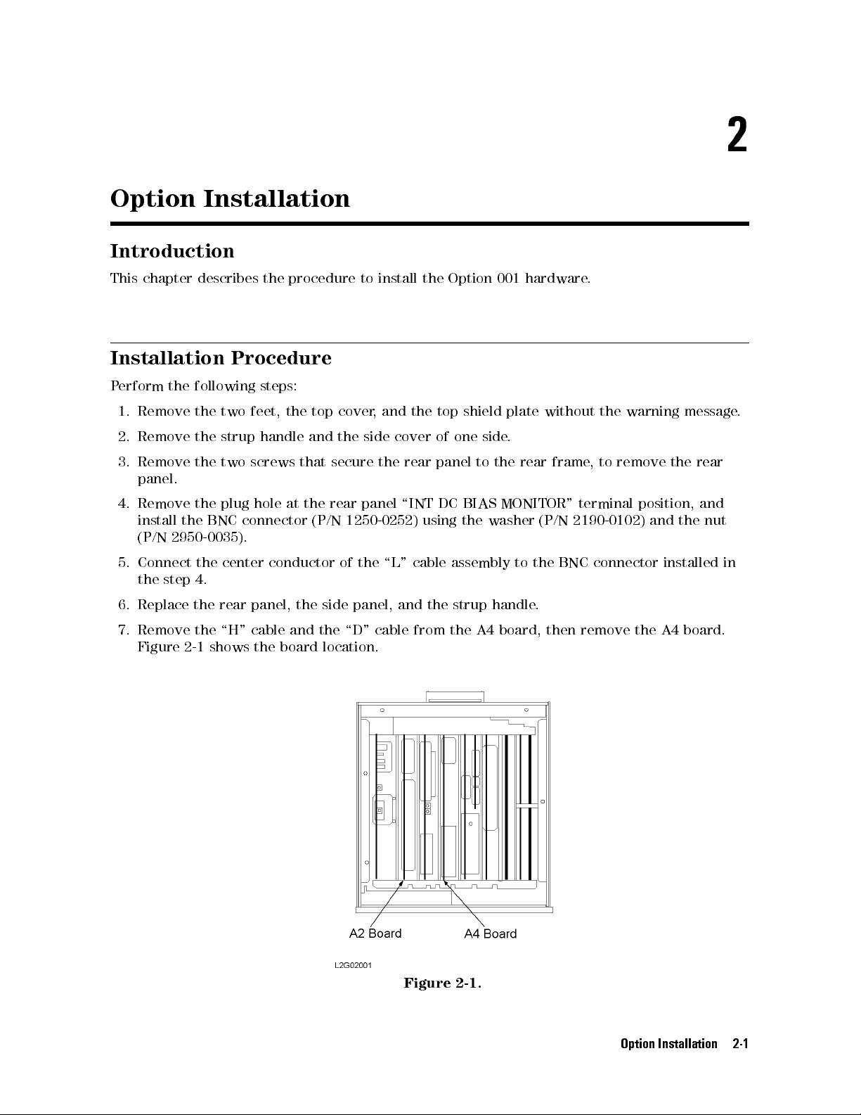
7.
Remove
Figure
the
2-1
shows the
\H"
cable and
board location.
the \D"
cable
Figure 2-1.
from
the
A4
board,
then
remove
the
A4
board.
Option Installation 2-1
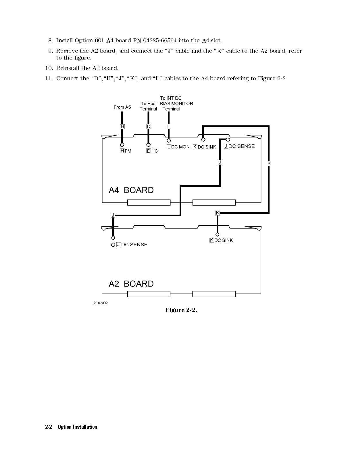
8. Install
Option 001
A4 board
PN 04285-66564
into the
A4
slot.
9. Remove
to the
gure.
10. Reinstall
11. Connect
the A2
the A2
board, and
board.
connect the
the \D",\H",\J",\K",
and \L"
\J" cable
cables
to
and
the
the
A4
\K"
board
cable
to
refering
the
to
A2
board,
Figure
2-2
refer
.
2-2 Option Installation
Figure
2-2.
12. P
erform the
following adjustments
according to
the service
manual.
a. DC
b. T
c. Impedance
13. P
erform the
a.
T
b.
T
c.
Impedance
d.
DC
14.
Put
Bias Level
est Signal
est
Signal
est
Signal
Bias
Level
\001"
label
Adjustment
Level/Monitor A
Measurement A
following
Level
Level
performance
Monitor
A
ccuracy
Measurement
A
ccuracy
PN
7120-0381
(Paragraph
djustment
djustment (P
tests
A
ccuracy
T
est
(P
A
ccuracy
T
est
(P
aragraph
on
the
2-12)
(P
aragraph
aragraph
according
T
est
(P
aragraph
T
est
(P
1-12)
left
side
2-14)
to
aragraph
1-8)
aragraph
of
the
2-13)
the
1-7)
1-9)
serial
maintenance
number
label.
manual.
Option Installation 2-3

 Loading...