

Page 1

HP
4 1952A/B
TRAN
SMWION/REFLECTION
TEST SET
@?zl
,HEWLETT
PACKARD
Page 2

COPYRIGHT AND DISCLAIMER NOTICE
Copyright - Agilent Technologies, Inc. Reproduced with the permission of Agilent
Technologies Inc. Agilent Technologies, Inc. makes no warranty of any kind with regard
to this material including, but not limited to, the implied warranties of merchantability
and fitness for a particular purpose. Agilent Technologies, Inc. is not liable for errors
contained herein or for incidental or consequential damages in connection with the
furnishing, performance, or use of this material or data.
Page 3

Table 1-2. Specifications (1 of 2)
Specificalions describe the instrument’s warranted performance over the temperature range of 23+5OC (except where noted). Supplemental characteristics are
intended to provide information useful in applying the instrument by giving non-
warranted uerformance uarameters. These are denoted as “typical”, “nominal”, or
“approximate”.
Impedance:
Frequency Range:
Directivity:
<300
kHz
300
kHz to 200 MHz
r200
MHz
Typical Frequency Response: ’
Transmission (Magnitude’, Phase’):
Reflection (Magnitude *, Phase’):
x300
kHt
300
kHz to 1 MHz +I cl& 3 deg
>I MHz
’ can be removed with the HP 4195A’s NORMALIZATION function
’ deviation from mean value
a deviation from linear phase *
HP 41952A
50 n
100 kHz to 500 MHz
30
dB
4OdE
35
d0
ii
d0.
$5
deg
+I dB. fi5 deg
+I cl& *5
deg
HP 419528
75n
100 ktlz to 500 MHz
30 dB
35dS
35-w
*I cIB, f5 deg
41 dB, *20 deg
*I dB, 510 deg
fl d6. f5 deg
Effective
Port Match (INCIDENT, REFLECTED and RF INPUT):
Insertion Loss (Nominal):
RF INPUT to TEST PORT:
RF INPUT to INCIDENT:
RF INPUT to REFLECTED:
Maximum Input Level:
RF !NPUT:
TEST FORT:
Source
<300
2300
kHt
kHz
,Match (TEST PORT):
215 dB
220
dB
220
dB
13
dB
19d0
19 dB
+20
dBm
+20
dBm
I-4
215:‘dB
220
dB
220
dt3
19 dB
31
dB
31
dB
+20,
,dBm
+20, dBm
Page 4

Damage Levet:
Table 1-2. Specifications (2 of 2)
HP 41952A HP 419528
RF INPUT:
TEST PORT:
TEST PORT:
RF INPUT:
INCIDENT and REFLECTED:
Operating Conditions:
Temperature:
Relative t-tumidity:
Option:
’ For 75R S-parameter measurements with the H@jif!4195A and two set of the
tw 419528.
1-23
dBm
+23
d&n
50 R Type N(f)
50
Cl Type N(f)
50
R Type N(m)
0 “C to 55 oc
<95%at40°C
+23,
dBm
423’
dBm
75
R Type N(f)
50
R Type N(f)
50 Ci Type N(m)
O,‘C to 55 UC
<95%at40 ‘C
r Option 009’ :
Del&e 50 R N cable
and HP 118528
Page 5

For The HP 41952A :
No. Description
(1) Test Set, SOR
[Z) N(m)-N(m) Cable. SOR
(3) Semi-rigid Cable, type N. 50R
(4) (Not furnished with the HP 41952A)
(5) Carrying Case
For The HP 419528 !
No.
Test Set. 75R
(1)
N(m)-N(m) Cable, 50R’
(2)
Semi+rigid Cable, type N. SOR
(3)
HP 118528 Minimum
(4)
Carrying Case
(5)
’ 5021 N(m)-N(m) cable and HP 118528 Minimum Loss Pad are not
included in the HP 419528 Option 009.
Description
Figure 2-1. Product Overview
LOSS
Pad. 5Dn-78R’
HP Par1 Number
PN 41952-65001
PN 8120-4666
PN 41982.61601
PN 41952-60001
HP Part Number
PN 41952-65002
PN 8120-4666
PN 41952-61601
HP 118528
PN 41952-60002
Page 6

SECTION
CONTENTS
This section provides the following information.
l
Overview
c Operator’s Check
c Typical Measurement Setups
l
Calibration Considerations
SECTION 3
OVERVIEW
Figure 3-1 shows the main features of the HP 41952A/E test sets
and their simple block diagrams, and the following description 1s
corresponded
(TO OUTPUT S)
to
each
features.
(2) INCIDENT connector (3) REFLECTED connector
(TO INPUT R)
(TO INPUT Tl
,,,.,’
I
(9) Semi-rigid Cable
Figure 3-1. HP 41952A/B Test Sets Features (i/2)
I
(4) TEST PORT connector
3-1
Page 7

TYPICAL
MEASUREMENT
SETUPS
This paragraph provides typical measurement setups using the
HP 41952A/B. The following setups are described.
. Transmission/Reflection Measurement
l
Using HP 41952A (50 S2)
l
Using HP 419528 (75 .Q)
l
S-parameter Measurement
l
Using HP 41952A (50 Cl)
l
Using HP 419528 (75 C!)
Do not mate a 50R type-N connector to a 7:5n type-N connector or damage may result.
Do not apply signals with power levels exceeding +23 dBm
to the RF INPUT and TEST PORT connectors or damage
may result.
Page 8

Measurements [Using the HP 41952A @On)]
Figure 3.3 shows typical measurement setup for a Transmission/
Reflection measurement of a 50R system.
HP 4195A
HP41952A _
,,,?”
%
DUT
Figure 3.3. Transmission/Reflection Measurement Setup Example
Using the HP 41952A (500)
Page 9

S-Parameler
Measurements
[Using the HP 41952A (5Of2)J
Figure 3-5 shows a typical measurement setup for making S-
parameter measurements of a 5Ofl system.
HP 4195A
41952A
Figure 3-5. S-Parameter Measurement Setup Exar&
Using the HP 41952A (Son)
,/
Page 10

CALIBRATION
CONSIDERATIONS
The HP 4195A provides calibration capabilities for enhancing
measurement accuracy. You can select from the following calibration functions (appropriate for your measurement) to compen-
sate for errors due to the test set. Refer to the HP 4195A Opera-
tion Manual for details.
l
For Transmission Measurements
. Normalize (Through) Calibration:
Compensates frequency response errors.
l
Normalize & Isolation Calibration:
Compensates frequency response and crosstalk
errors.
l
For Reflection Measurements
l
Normalize (Open) Calibration:
Compensates frequency response errors.
. One Port Partial Calibration:
Compensates frequency response and directivity
errors.
Calibration
Standard Values
HP 850326
N(m) connector
HP 850328
N(f) connector
HP 850368
N(m) connector
l
One Port Full Calibration:
Compensates frequency response, cfirectivity, and
source mismatching errors.
The standard values for reflection calibration are stored In the
HP 4195A’S memory, and these values can be modified to match
,,“,your standards. Use the values listed in Table 3-1 for the stan-
dard values when using the HP 880328 of HP 850368 callbratlon
kit.
Table 3-i. Standard Values
SHORT LOAD
0 Dl.
Q PI.
878E-12 [W]
Q [HI
60 [i-i]. 0 [Ii]
50
m 0 WI *
75 h-4, 0 1q
0 PI.
Q ts1.
0 m
OPEN
413E-15 [F]
108E-15 [F]
275E-15 [F] 0 [fl]. 1317E-12 [H]
HP 650368
N(l) connector
0 IS), 635E-14 [f] .’ 0 [I-I].
3-I 1
Q WI
75,[R$ 0 [W]
Page 11

PERFORMANCE TESTS
SECTION 4
INTRODUCTION
This section provides the performance test procedure to ensure
that the HP 41952A/B meets the specifications listed in Table i-3.
Specifications. The performance test can be performed without
accessing the interior ot the HP 41952A/B.
The test results should be recorded into the Performance Test
Record located at the end of this section.
EQUlPMENT REQUIRED
The equipment required for performance testing Is listed in Table
4-1. Substitutions can be made for the equipment in this list if
the specifications meet or exceed the specifications listed in the
Reauirements column.
Table 4.1. Recommended Test Equipment
Equipment
Recommended Model
Network Analyzer
HP 4195A
aty.
I No substitute
Requirements
Tfl Test Set
HP 41952A
Calibration Kit
HP 850328
Calibration Kit
HP 850368 l ’
Terminatlon
HP 909c opt.200. opt.012 “’
Termination
HP 909F Opt.012 F *
Adapter I
.:
Note:
*’ Used for performance testing the HP 419528.
* * Used for performance testing the HP 41952A.
No substitute
1 No substitute
(use open/short/SO R termination)
I No substitute
(use open/short/75 C termination)
1
I
1
Type N(m), 50 R ”
Frequency: 5 200 MHz
Return Loss: 2 52 dB
Type N(m), 50 R
Frequency: 106 kHt to 500, MHz
Return Loss: L 47 dB
N(f)-N(f). 50 tl
N(m)-N(m). 50 R
4-I
Page 12
CALIBRATION CYCLE
The HP 41952A/B requires periodic performance verification. The
HP 41952A/B should be checked out using the performance test
at least once a year or more depending on the frequency of use.
Preventive maintenance should be performed at least twice a year
to keep down-time to a minimum, and to ,lnsure optimum
operation.
-
-
PREPARATION
t
This paragraph provides the information you need to know, and
the steps you must perform before starting the performance test.
1.
The test equipment must be allowed to warm-up and stabilize
for at least 30 minutes.
2.
An HP 4195A is required to performance test the HP 4t952A/
6. In the remainder of this manual, the HP 4195A’s softkeys
are indicated in boldface type and are enclosed In single
quotes (e.g., ‘NETWORK’ softkey). and keys are indicated in
bold face type only (e.g., PRESET key).
3.
The HP 4195A’s calibration capability is used to performance
test the HP 41952A/B. Perform the procedure given below to
change the calibration standard data stored in the HP 4195A
before running the performance teat. If you are testing a
HP 41952A. perform steps a and b. If you are testing a
HP 419528. perform steps a through d.
a. Turn the HP 4195A ON. and sequentially press the PAE-
SET and CAL keys, and the ‘more, 112’ and ‘CAL STD
modify’ softkeys.
b. Sequentially press the following keys.
*OPEN CAL STD. 0. green shiftkey, , (COmma)
4 t 1 ,3 , EEX, - (minus), 1 ,5 , ENTER/EXECUTE
‘SHORT CAL STD’. 0 , green shiftkey, ,’ (comma)
8.7.8 , EEX. - (minus), 1 ,2, ENTER/EXECUTE
‘LOAD CAL
STW,
5 , 0 , green shiftkey,, (Comma)
0, ENTER/EXECUTE
4-2
Page 13

C. Sequentially press the HP 4195A’s CAL key, ,and the
‘more l/2’,
softkeys.
d. Sequentially press the following keys.
‘OPEN CAL STD., 0, green shiftkey, , (comma)
2,7 ,5, EEX. - (minus), 1 ,5, ENTER/EXECUTE
‘SHORT CAL STD’, 0 , green shiftkey,, (comma)
1 ,3,1 ,7, EEX, - (minus), 1 ,2, ENTER/EXECUTE
‘LOAD CAL STD’, 7 , 5 , green shiftkey, , (comma)
0, ENTER/EXECUTE
‘ZU 50R 75R’ and the ‘CAL STD modify’
Page 14
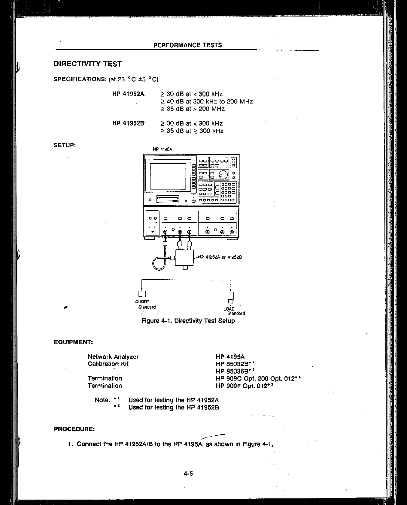
C)IRECTIVITY TEST
SPECIFICATIONS: (at 23 “C +5 “C)
HP 41952A: 2 30 cl6 at r 300 kHz
HP 419520: 2 30 dB at < 300 kHt
SETUP:
2 40 dB at 300 kHz to 200 MHz
2 35 dB at r 200 MHz
2 35 dB at 2 300 kHz
2l
SHORT
Slaniilrd
,’
Figure 4-I. Directivity,Tsst Setup
EQUIPMENT:
Network Analyzer HP 4195A
Calibration Kit HP 950328”
,,.,
Termination
Termination
Note: *’ Used for testing the HP 41952A
+’ Used for testing the HP 419528
PROCEDURE:
,/--,-- “’
1. Connect the HP 41952A/B tc the HP 4195A; as shown In Ffgure 4-l.
e
LOi0 ”
Sh”da,d
HP 8.50360”
HP 909C Opt. 200 Opt. 012”
HP 909F Opt. 012* *
4-5
Page 15

PERFORMANCE TESTS
2. Sequentially press the following HP 4195A from panel keys.
CONFIG, ‘NETWORK’, PRESET
AMPLITUDE (CHANNEL 1 side), 1 , 0 , ENTER/EXECUTE
REF ATTEN (CHANNEL 1 side), 1 , 0 , ENTER/EXECUTE
TEST ATTEN (CHANNEL 1 side), I , 0 , ENTER/EXECUTE,
START, 1 , 0 , 0 , kHz/dBm
RES EW, 1 , kHz/dBm
MENU, ‘TRIGGER menu’. ‘SINGLE mode’, ‘return’
‘TYPE lin log’ (“log” in the ‘TYPE lin log’ softkey will change to
intensified green,)
DISPLAY. ‘TRACE B on off’
(“off- in the ‘TRACE 6 on off’ softkey will change
to intensified green.)
NOTE
If you are testing the HP 419528. skip step 3.
3. Press the following keys, and skip step 4.
STOP, 2,0,0, MHz/V
Press the following keys (only for testing the HP 419,528).
STOP,S,O.O,MHz/V
CAL, ‘more l/2’, ‘20 5OSi 75R’
(“75R” in the ‘20 50R f5G’ softkey will change to intensified green.)
Connect the N(m) SHORT standard to the HP 41952A/B’s TEST PORT connector.
Press the TRIG/RESET key on the HP 4195A’s front panel,‘to make a single
measurement.
Enter the HP 4195A “C=A” command using the following keystrokes.
CLR LINE. blue shiftkey, C , = , A , ENTER/EXECUTE
sweep
Connect the N(m) LOAD standard (HP 909C Opt. 200. Opt. 012 for testing
HP 41952A. HP 85036B’s 75 R standard (65036-60008) for testing HP 419528) to the
HP 41952A/B’s TEST PORT connector.
Press the HP 4195A’s TRIG/RESET key.
4-6
Page 16

PERFORMANCE TESTS
IO.
Enter the HP 4195A “A&-A” command using the following keystrokes to have the
HP 4195A display the Directivity Test results.
CLR LINE, blue shiftkey, A, = , C , - (minus) , A , ENTER/EXECUTE
11.
Press the SCALE REF key and the ‘A AUTO SCALE’ softkey for auto scaling.
12.
Sequentially press the following keys to set the HP 4195A’s analysis range between
100 kHz and 300 kHz.
MORE, ‘ANA RNG’
(move the * marker to the point as close as possible to 300 kHz by rotating the
HP 4195A’s rotary knob.)
-
‘active oMKR .MKW
(“oMKA” in this softkey will change to intensified
green.)
(move the o marker to the 100 kHz point)
‘STORE ANA RNG’
‘PART ANA on off’
(-on” in this softkey will change to intensified
green.)
13.
Press the MKR+ key and ‘MKWMIN’ softkey.
14. Confirm that the T/R data displayed on the upper right corner of the HP 4195A’s
display (Dlrectivity Test result) is within the test limits listed in Table 4-2, Dtrectivity
Test Limit.
15. Sequentially press the following keys to set the HP 4195A’s analysts range between
300 kHz. end the stop frequency point (200 MHz for testlng a HP 41952A, or
500 MHz for testing a HP 419528).
_
MORE, ‘ANA ANG’
(move o marker to the STOP frequency point)
‘STORE ANA ANG
16. Press the MKR+ key and WKP+MINr softkey.
17. Confirm that the T/R data displayed on the upper right corner of, the HP 4195A’s
display (Directivity Test result) is within the test limits listed in Table 42. Directivlty .
Test Limits.
NOTE
If YOU are testing a HP 419528. do not perEm$tep IS.,
,,_. ‘, --,
Page 17

PERFORMANCE TESTS
18. Perform steps a through j only when testing a HP 41952A.
a.
Sequentially press the following HP 4195A keys.
START, 2 , 0 , 0 , MHz/V
STOP, 5, 0, 0 , MHz/V
Connect the HP 850328’s N(m) SHORT standard (HP 11512A) to the
b.
HP 41952A’s TEST PORT connector.
c.
Press the HP 4195A front panel TRIG/RESET key to perform a single sweep
measurement.
d.
Enter the HP 4195A “GA” command using the following keystrokes.
CLR LINE. blue shiftkey. C , = , A , ENTER/EXECUTE
8.
Connect a the 50 Q Termination (HP 909F Opt. 012) to the HP 41952A’s TEST
PORT
connector.
Press the HP 4195A TRIG/RESET key.
Enter the HP 4195A “A=C-A” command using the following ,keystrokes to have
the HP 4195A display the Directivity Test results.
CLR LINE. blue shiftkey, A , = , C , - (minus), A, ENTER/EXECUTE
h.
Press the SCALE AEF key and ‘A AUTO SCALE’ softkey for
i.
Sequentially press the
Confirm that the T/R data displayed in the upper right corner of the HP 4195A’s
i.
MKW
key and the ‘MKR-tMIN softkey.
auto
Scaling.
display (Directivity Test result) Is within the test limits listed in Table 4-2, DlreCtiVi-
ty Test Limits. _ _
I
HP 41952A:
31
I
Table 4-2. Directivity Test Limits
I
J
HP 419520:
I
Frequency
Test Limit
-z 300
kHt
r... ,..--2-‘300 kHz
2 30 de
2 35 d0
4-,9
Page 18

EFFECTIVE SOURCE MATCH TEST
SPECIFICATIONS: (at 23 “C f5 “C)
SETUP:
TEST PORT:
$
OPEN
Standard
~15dBat~300kHz
2 20 dB at 2 300 kHt
HP 4t95A
P P1952A or 419526
b
SHORT
Standard LOAD
,........, . . . ..~
b
Standard
Figure 4-2. Effective Source Match Test Setup
EQUIPMENT:
I
PROCEDURE:
1. Connect the HP’41952A/B to tlie HP 4195A. & shown in .Figurti 4-2.
Network Analyzer
Calibration Kit
Note: * ’ Used for testing the HP 41952A
* * Used for testing the HP 419528
HP 4195A
HP 850328” ’
HP 85036B”’
../ “.‘I
,- ,-::.y-‘.
Page 19

PERFORMANCE TESTS
2. Sequentially press the following HP 4195A front panel keys,
CONFIG. ‘S-PRMTR’, ‘Si I’, PRESET
AMPLITUDE (CHANNEL 1 side), 1 , 0 , ENTER/EXECUTE
REF ATTEN (CHANNEL 1 side), 1 , 0 , ENTER/EXECUTE
TEST ATTEN (CHANNEL 1 side), 1 , 0 , ENTER/EXECUTE
START, 1 , 0 , 0 , kHz/dDm
STOP, 5,0,0, MHz/V
RES BW, 1 , kHz/dBm
MENU. ‘TRIGGER menu’. ‘SINGLE mode’, ‘return’
‘TYPE lin tog’ (“log” in the ‘TYPE lin log’ Softkey will change to
intensified green.)
DISPLAY, ‘TRACE 6 on off
(“ofl” in the ‘TRACE B on off’ softkey will change
to intensified green.)
NOTE
If you are testing a HP 41952A, skip step 3.
3.
Press the following keys (only when testing a HP 419528).
CAL, ‘more l/2’, ‘ZO 50R 75R
,/
(the “75R” in the ‘ZO 60R 75R’ soflkey will change to intensified green.)
I
Sequentially press the HP 4195A’s CAL key, and the ‘S-PAMTR CAL menu’ and ‘ONE
4.
PORT FULL CAL’ softkeys.
Connect the N(m) OPEN standard to the HP 41952A/B’s TEST PORT connector.
5.
Press the ‘OPEN’ softkey and the ENTER/EXECUTE key.. Wait until the single sweep
6.
measurement is completed.
Connect the N(m) SHORT standard to the HP 41952A/B’s TEST PORT connector.
Press the ‘SHORT’ softkey and the ENTER/EXECUTE key. Wait Unflf ‘the Single
sweep measurement is completed.
Connect the N(m) LOAD standard to the HP 41952A/B’s TEST PORT connector.
Press the ‘LOAO”sOftkey and the ENTER/EXECUTE key. Wail until the single sweep
measurement is completed.
.4-10 ‘,
,,.+I,
Page 20

PERFORMANCE TESTS
11. Press the ‘CAL’ key and the ‘CORRECTN on off’ softkey. “on” in this softkey will
change to intensified green.
12. Press the PROGRAM key, the ‘EDIT’ softkey and the ENTER/EXECUTE key, In sequence. The HP 4195A’s display will change to the user program editor display.
13. Enter the following HP 4’196A program to have ii’display the Elfective Source Match
test results. If you need more information on how to enter a HP 4195A program,
refer to the HP 4195A’s Operation Manual, paragraph 6-4, USER PROGRAM (Auto
Sequence Program:ASP).
10
<RA,RB> = <MFOR.MFOl> . <TFSR,TFSI>
20
<RA,RB> = <RA,RB> - cMFSR.MFSl> * <TFOR.TFOI>
30
<RA.RB> = <RA,RB> + <MFLR.MFLI> * (<TFOR,TFOI> - <TFSR,l-F$I>)
40
<RC.RD> = <MFOR,MFOI> f cTFOR,TFOl> . <TFSR.TFSl>
50
<RC.RD> = <RC,RDr - <MFSR.MFSlr * <TFSR.TFSl> + <TFOR,TFOl>
<R&RF> - <RA,RB> / <RC.RDr
60
70
A=-20*LOG(SQR(RE.REtRF.RF))
60
END
Note: To display * c “, press the green shiftkey and < key.
To display ” > *, press the green shiftkey and > key.
TO display ” , “, press the green shiftkey and , (comma) key.
To display * . ‘, press the MATH OPERATOR key and ’ - ’ softkey.
To display ” + “, press the MATH OPERATOR key and ‘ t ’ softkey.
To display ” / *. press the MATH OPERATOR key and ‘ / ’ softkey
To display ” ( *, press the MATH OPERATOR key and ’ ( ’ softkey.
To display * ) “, press the MATH OPERATOR key and ’ ) ’ softkey.
To display any alphabet key. let the LED, indicator in the blue shiftkey
light, and press any alphabet key.
-
14. Sequentially press the PROGRAM key and the ‘QUIT editor’ and ‘RUN’ softkeys.
Wait until the ‘STOP’ softkey changes to intensified green.
15. Press the SCALE REF key and, the ‘A AUTO SCALE’ softkey for auto scaling.
,/
Page 21

PERFORMANCE TESTS
Sequentially press the following keys to set the HP 4195A’s analysis range between
16.
100 kflz and 300 kHz.
MORE, ‘ANA RNG’
(move the .
marker to a point as close as possible to 300 kHz by rotating the
HP 4195A’s rotary knob)
‘active oMKR MKR’ (“oMKR” in this softkey will change to intensified
green.)
(move the o marker to the 100 kHz point)
‘STORE ANA RNG’
‘PART ANA On Off’
(“on” in this softkey will change to intensified
green,)
17.
Press the MKR+ key and the ‘MKR+MIN’ softkey.
,.,
18.
Confirm that the data RL displayed on the upper right comer of the HP 4195A’s
display (Effective Source Match Test result) is within the test limits listed in Table 4-3,
Effective Source Match Test Limits.
19.
Press the following keys in sequence, to set the HP 4195A’s analysis range between
300 kllz and 500 MHz.
MORE, ‘ANA RNG’
(move o marker to 500 MHz point)
‘STORE ANA RNG’
20.
Press the
MKR-
key and the ‘MKR+MIN’ softkey.-
/,”
21.
Confirm that the data RL displayed on the upper r’fght corner of the HP 4105A’S
disolav (Effective Source Match Test result) is within the test limits listed in Table 4-3.
I
Effective Source Match Test Limifs.
Table 4-3. Effective Source Match Test Limits
4.12
Page 22

PERFORMANCE TESTS
PORT MATCH TEST
SPECIFICATIONS: (at 23 “C f5 “C)
SETUP:
INCIDENT, REFLECTED. RF INPUT:
OPEN
Standard
2 20 CIB
Figure 4-3. HP 41952A Calibration Setup
EQUIPMENT:
Network Analyzer HP 4195A
I
T/R Test Set
Calibration Kit HP 850328
50 Q Termination ,,, HP 909F Opt. 012”
Adapters
Note: * ’ Test equipment required to test the HP
*f Used for testing the HP 419528
l
’ Used for testing the HP 41952A
PROCEDURE:
1. Connect the HP 41952A to the HP 4195A.
HP 41952A”
HP 85036B* *
as necessary
41952A/B
under test
Page 23

PERFORMANCE TESTS
.,
2. Turn Ihe HP 4195A OFF and ON to initialize it. and then sequentially press the lollowing HP 4195A front panel keys.
CONFIG, ‘S-PRMTR’, ‘211 l’, PRESET
AMPLITUDE (CHANNEL I side), 1 , 0 , ENTER/EXECUTE
REF ATTEN (CHANNEL 1 side), 1 , 0 , ENTER/EXECUTE
TEST ATTEN (CHANNEL 1 side), 1 , 0 , ENTER/EXECUTE
START, 1 , 0 , 0 , kHz/dBm
STOP, 5,0,0, MHz/V
RES BW. 1 , kHt/dBm
MENU, ‘TRIGGER menu’. ‘SINGLE mode’
DISPLAY. ‘TRACE B
on
off’
(“off” in the ‘TRACE B on off’ softkey will change
to intensified green,)
Perform the following procedure (steps a through h), to perform a 1 PORT FULL
CALIBRATION for the TEST PORT connector of the HP 41952A (test
equipment).
Sequentially press the HP 4195A’s CAL key, and the ‘S-PRMTR CAL menu’ and
‘ONE PORT FULL CAL’ softkeys.
b.
Connect the HP 850328’s N(m) OPEN standard to the TEST PORT connector of
the HP 41952A (test equipment).
Press the ‘OPEN’ softkey and the ENTER/EXECUTE key. Wait until the single
sweep measurement is completed.
ct.
Connect the HP 850328’s N(m) SHORT standard to the TEST PORT connector
of the HP 41952A (test equipment).
8.
Press the ‘SHORT’ softkey and ENTER/EXECUTE key, Wait until the single
sweep measurement is completed.
f.
Connect the HP 850328’s N(m) LOAD standard to the TEST: PORT connector of
the HP 41952A (test equipment).
Press the ‘LOAD’ softkey and the ENTER/EXECUTE key: Wait until the single
sweep measurement is completed.
h.
Press the CAL key and the LCORRECTN on olt’ softkey. The “on” in this softkey
:., “’
will change to intensified green.
.A------ “‘.
._.--,
,,.
4-f4
Page 24

PERFORMANCE TESTS
4. Perform the following procedure (steps a through i) to test the Port Match for the
INCIDENT (R) connector of the HP 41952A/B (under test).
.,
TO HP 4195ZA ,,esr aq”ipmentl
TESl PORT Connecfor
Figure 4-4. INCIDENT connector Port Match Test Setup
Connect the N(m) LOAD standard (909F Opt. 012 for testing the HP 41952A,
a.
HP 850368’s 75 5-I standard for testing the HP 419528) to the TEST PORT connector of the HP 41952A/B (under test).
Connect the HP 850328’s N(f) LOAD standard to the REFLECTED (T) connector
b.
of the HP 41952A/B (under test).
Connect the HP 85032B’s N(m) LOAD standard to the RF INPUT connector of
C.
the HP 41952A/6 (under test), as shown in Figure 4-4.
d.
Connect the INCIDENT (R) connector of the HP 41952A/B (under test) to the
TEST PORT connector of the HP 41952A (test equipment).
e.
Press the HP 4195A’s TRIG/RESET
f.
Enter the HP 4195A “A=-A” command using the following key stroke sequence to
I
5. Disconnect the HP 41952A/B (under test) from the HP 41952A (test equipment).
have the HP 4195A display the Port Match test
CLR LINE. blue shiftkey. A , = , - (minus), A , ENTER/EXECUTE
Press the SCALE REF key and the ‘A AUTO SCALE’ softkey for auto scaling.
9.
h.
Press the MKR-, key and the ‘MKWMIN’
mlnlmum point.
I.
Confirm that the RL data displayed’ on the upper right corner of the HP 419SA’s .
display (Port Match test result) is greater than or equal to 20 dB1
key,
to make a-single sweep measurement.
results.
softkey
to move the o marker to the
6. Disconnect the HP 850328’s N(f) LOAD standard from the REFLECTED (T) connector of-ihe HP 41952A/B (under test).
Page 25

PERFORMANCE TESTS
-
7. Perform the following procedure (steps a through g) to test the Port Match for the
REFLECTED (T) connector of the HP 41952A/B (under test).
Figure 4-5. REFLECTED connector Port Match Test Setup
a.
Connect the HP 850328’s N(f) LOAD standard to the INCIDENT (R) connector of
the HP 41952A/B (under test), as shown in Figure 4-5.
Connect the REFLECTED (T) connector of the HP 41952A/B (under test) to the
b.
TEST PORT connector of the HP 41952A (test equipment).
C.
Press the HP 4195A’s TRIG/RESET key to make a single sweep measurement.
Enter the HP 4195A “Am-A” command using the following key sequence to have
d.
the HP 4195A display the Port Match test result.
CLR LINE. blue shiftkey, A , = , - (minus), A , ENTER/EXECUTE
e.
Press the SCALE REF key and the ‘A AUTO SCALE’ softkey for
1.
Press the MKR-r key and the ‘MKWMIN’ softkey to move the o marker to the
auto
scaling.
minimum point.
Confirm that the RL data displayed on the upper right corner of the HP 4195A’s
display (Port Match test result) is greater than or equal to 20 dB.
Disconnect the HP 41952A/B (under test) from the HP 41952A (test equipment),.
Disconnect the HP 650328’s N(m) LOAD standard and N(f) LOAD standard from the
RF INPUT connector and the INCIDENT connector 01 the HP 41952A/B (under test).
respectively.
Connect the N(m)-N(m) Adapter to the TEST PORT connector of the HP 41952A (test
equipment).
4-16
Page 26

PERFORMANCE TESTS
11. Use the following procedure (steps a through k), to perform a 1~ PORT FULL CALIBRATION for the adapter on the TEST PORT connector of the HP 41952A (test
equipment).
Sequentially press the HP 4195A’s CAL key, and the CORRECTN on off’. ‘more
a.
l/2’. and ‘CAL STD modify’ softkeys.
b.
Sequentially press the fallowing keys to change the HP 4195A’s stored standard
calibration data.
‘OPEN CAL STD’, 0 , green shiftkey,, (comma),
1 , 0 , 8
EEX, - (minus), 1 ,5 , ENTER/EXECUTE
‘SHORT CAL STD’, 0 , green shiftkey,, (comma), 0, ENTER/EXECUTE
c.
Press the MENU key (once) and the ‘TYPE lin log’ softkey (twice).
d.
Sequentially press the HP 4195A’s CAL key, and the %-PRMTR CAL menu’ and
the ‘ONE PORT FULL CAL’ softkeys.
e.
Connect the HP 850328’s N(f) OPEN standard to the adapter on the TEST PORT
connector of the HP 41952A (test equipment).
f.
Press the ‘OPEN’ softkey and the ENTER/EXECUTE key. Wait until the single
sweep measurement is completed.
Connect the HP 850328’s N(f) SHORT standard to the adapter on the TEST
PORT connector of the HP 41952A (test equipment).
h.
Press the ‘SHORT’ softkey and the ENTER/EXECUTE key. Wait
UI’Itil
the
sweep measurement is completed.
i.
Connect the HP 850328’s N(f) LOAD standard to the adapter on the TEST PORT
connector;f the HP 41S52A (test equipment). .,
Single
Press the ‘LOAD’ softkey and the ENTER/EXECUTE key. Wait until the single
L
sweep measurement is completed.
k.
Press the CAL key and the ‘CORRECTN on off’ softkey.
Perform the following procedure (steps a through h) to test the Port Match for the RF
INPUT connector of the HP 41952A/B,(under test).
Page 27

PERFORMANCE TESTS
Figure 4-6. RF INPUT connector Port Match Test Setup
a.
Connect the HP 850328’s N(f) LOAD standard to the REFLECTED (T) connector
of the HP 41952A/B (under test).
b.
Connect the HP 850328’s N(m) LOAD standard to the INCIDENT (R) connector
of the HP 41952A/E (under test) using the N(f)-N(f) Adapter, as shown in Figure
4-6.
#
C.
Connect the RF INPUT connector of the HP 41952A/B (under test) to the adapter
on the TEST PORT connector of the HP 41952A (test equipment).
d.
Press the HP 4195A’s TRIG/RESET key to make a single sweep measurement.
Enter the HP 4195A “A=-A” command using the following key stroke sequence
e.
to have the HP 4195A display the Port Match test results.
CLR LINE, blue shiftkey, A , = , - (minus), A , ENTER/EXECUTE
f.
Press the SCALE REPkey and the ‘A AUTO SCALE’ softkey for auto scaling.
Press the MKR-, key and, the ‘MKWMIN’ softkey to move the o marker to the
9.
minimum point.
Confirm that the RL data displayed on the upper right corner of the HP 4195A’s
h.
display (Port Match test result) is greater than or equal to 20 dB
.
Page 28

PERFORMANCE TEST RECORD
Hewlett-Packard
Model 41952A
Transmission/Reflection Test Set
DIRECTIVITY:
Min. at f < 300 kHz:
Min. at 300 kHz C f 1200 MHz:
Min. at f r 200 MHz:
EFFECTIVE SOURCE MATCH:
Min. at
Min. at
PORT
f < 300 kHz:
f 2 300 kHz:
MATCH: ,,,, /-
b
Min. for INCIDENT:
Specification
2: 30 d0
Z4OdB
5 35 dB
Specittcation
2 15dB
2 20 CIB
Specification
2 20
dB
Actual
dB
cl6
dB
Actual
Actual
cl6
Min. for REFLECTED:
Min. for RF INPUT:
Z2OdB
12QdB
/L.“” ‘-’
..:5-- ,,
..c,
dB
dB
 Loading...