

Page 1
HP 41802A 1 M Input Adapter
Operation Note
SERIAL NUMBERS
This manual applies directly to HP 41802As with serial number prex 3103J.For additional
important information about serial numbers, read \Serial Number" in Chapter 1.
ABCDE
HP Part No. 41802-90000
Printed in Japan February, 1999
2nd Edition
Page 2

c
Copyright 1991,1999 Hewlett-Packard Japan, LTD.
Page 3
Certication
Hewlett-Packard Company certies that this product met its published specications at the
time of shipment from the factory. Hewlett-Packard further certies that its calibration
measurements are traceable to the United States National Institute for Standards and
Technology, to the extent allowed by the Institution's calibration facility, or to the calibration
facilities of other International Standards Organization members.
Warranty and Assistance
All Hewlett-Packard products are warranted against defects in materials and workmanship.
This warranty applies for one year from the date of delivery,or, in the case of certain
major components listed in the operating manual, for the specied period. We will repair or
replace products which prove to be defective during the warranty period provided they are
returned to Hewlett-Packard. No other warranty is expressed or implied. We are not liable for
consequential damages.
For any assistance, contact your nearest Hewlett-Packard Sales and Service Oce.Addresses
are provided at the back of this manual.
Limitation of Warranty
The foregoing warranty shall not apply to defects resulting from improper or adequate
maintenance by Buyer, Buyer-supplied software or interfacing, unauthorized modication or
misuse, operation outside of the environment specications for the product, or improper site
preparation or maintenance.
No other warranty is expressed or implied. HP specically disclaims the implied warranties
of merchantability and tness for a particular purpose.
iii
Page 4

Caution
The HP 41802A is sensitive to electrostatic discharge (ESD). The followings
must be adhered to when using the HP 41802A.
Do
NOT
touch the center conductor of the BNC connector of the HP
41802A.
Do
NOT
touch the pin of the probe which is connected to the HP 41802A.
Eliminate ESD on your body.
Eliminate ESD on the work surface.
Do
NOT
introduce ESD into the DUT, while the HP 41802A and the probe is
in use.
iv
Page 5

Contents
1. General Information
Introduction . . . . . . . . . . . . . . . . . . . . . . . . . . . . . . . . . 1-1
Compatible Equipment . . . . . . . . . . . . . . . . . . . . . . . . . . . . 1-2
Compatible Instruments .......................... 1-2
Compatible Probes . . . . . . . . . . . . . . . . . . . . . . . . . . . . . 1-2
Serial Number . . . . . . . . . . . . . . . . . . . . . . . . . . . . . . . . 1-3
Specications ................................ 1-4
Supplemental Performance Characteristics ...... ...... ...... 1-5
2. Installation
Introduction . . . . . . . . . . . . . . . . . . . . . . . . . . . . . . . . .
Initial Inspection . . . . . . . . . . . . . . . . . . . . . . . . . . . . . . .
Power Requirements . . . . . . . . . . . . . . . . . . . . . . . . . . . . .
Mating Connectors . . . . . . . . . . . . . . . . . . . . . . . . . . . . . .
Environmental Requirements . . . . . . . . . . . . . . . . . . . . . . . . .
3. Operation
Introduction . . . . . . . . . . . . . . . . . . . . . . . . . . . . . . . . .
Operating Precautions ............................
Anti-static Precautions . . . . . . . . . . . . . . . . . . . . . . . . . . .
Maximum Allowable Level . . . . . . . . . . . . . . . . . . . . . . . . .
Discharging the Probe .. ...... ...... ...... ...... .
Probe Power Plug .. ...... ...... ...... ...... ...
Preparation for Use .............................
Operating Check Using a Network Analyzer . . . . . . . . . . . . . . . . .
Using an HP 8751A or HP 3577A/B Network Analyzer . . . . . . . . . . .
Equipment Required . . . . . . . . . . . . . . . . . . . . . . . . . . 3-4
Procedure . . . . . . . . . . . . . . . . . . . . . . . . . . . . . . . 3-4
Using HP 8753A/B/C Network Analyzer . . . . . . . . . . . . . . . . . . 3-5
Equipment Required . . . . . . . . . . . . . . . . . . . . . . . . . . 3-5
Procedure . . . . . . . . . . . . . . . . . . . . . . . . . . . . . . . 3-5
Operating Check Using a Spectrum Analyzer .. ...... ...... ..
Equipment Required . . . . . . . . . . . . . . . . . . . . . . . . . . .
Procedure . . . . . . . . . . . . . . . . . . . . . . . . . . . . . . . .
Operating Check Using a Network/Spectrum Analyzer ............ 3-7
Equipment Required . . . . . . . . . . . . . . . . . . . . . . . . . . .
Procedure . . . . . . . . . . . . . . . . . . . . . . . . . . . . . . . .
Adjusting the Probe ............................
Using a Network Analyzer ...... ...... ...... ..... .
Equipment Required . . . . . . . . . . . . . . . . . . . . . . . . . . 3-8
Procedure . . . . . . . . . . . . . . . . . . . . . . . . . . . . . . . 3-8
Using a Spectrum Analyzer . . . . . . . . . . . . . . . . . . . . . . . .
Equipment Required . . . . . . . . . . . . . . . . . . . . . . . . . .
Procedure . . . . . . . . . . . . . . . . . . . . . . . . . . . . . . .
Typical Measurement Setups .... ...... ...... ...... ...
Network Measurements ..........................
2-1
2-2
2-3
2-3
2-4
3-1
3-2
3-2
3-3
3-3
3-3
3-3
3-4
3-4
3-6
3-6
3-6
3-7
3-7
3-8
3-8
3-10
3-10
3-10
3-11
3-12
Contents-1
Page 6

Using One HP 41802A .......................... 3-12
Using One HP 41802A with a Transmission/Reection Test Set ....... 3-13
Using Two HP 41802As ......................... 3-14
Spectrum Measurements . . . . . . . . . . . . . . . . . . . . . . . . . . 3-15
Using HP 41802A with instruments which have BNC connectors ....... 3-16
4. Performance Test
Introduction . . . . . . . . . . . . . . . . . . . . . . . . . . . . . . . . . 4-1
Equipment Required . . . . . . . . . . . . . . . . . . . . . . . . . . . . . 4-1
Calibration Cycle .............................. 4-2
Preparation . . . . . . . . . . . . . . . . . . . . . . . . . . . . . . . . . 4-2
Gain Accuracy/Flatness Tests . . . . . . . . . . . . . . . . . . . . . . . . . 4-3
Description ................................ 4-3
Specications ............................... 4-3
Test Equipment .............................. 4-3
Procedure . . . . . . . . . . . . . . . . . . . . . . . . . . . . . . . . . 4-3
Performance Test Record . . . . . . . . . . . . . . . . . . . . . . . . . . . 4-6
Gain Accuracy/Flatness Tests . . . . . . . . . . . . . . . . . . . . . . . . 4-6
5. Adjustment
Introduction . . . . . . . . . . . . . . . . . . . . . . . . . . . . . . . . .
Equipment Required . . . . . . . . . . . . . . . . . . . . . . . . . . . . .
Preparation . . . . . . . . . . . . . . . . . . . . . . . . . . . . . . . . .
Gain Adjustment . . . . . . . . . . . . . . . . . . . . . . . . . . . . . . .
Description ................................
Equipment ................................
Procedure . . . . . . . . . . . . . . . . . . . . . . . . . . . . . . . . .
5-1
5-1
5-1
5-2
5-2
5-2
5-2
6. Replaceable Parts
Replaceable Parts Lists . . . . . . . . . . . . . . . . . . . . . . . . . . . .
A. Manual Changes
Introduction . . . . . . . . . . . . . . . . . . . . . . . . . . . . . . . . .
Manual Changes . . . . . . . . . . . . . . . . . . . . . . . . . . . . . . .
6-1
A-1
A-1
Contents-2
Page 7
Figures
1-1. Serial Number Plate .... ...... ...... ...... ...... 1-3
1-2. Specications ........ ...... ...... ...... ..... 1-4
1-3. Supplemental Characteristics . . . . . . . . . . . . . . . . . . . . . . . . 1-5
2-1. Product Overview . . . . . . . . . . . . . . . . . . . . . . . . . . . . . 2-2
2-2. Probe Power Requirements . . . . . . . . . . . . . . . . . . . . . . . . . 2-3
3-1. Operating Check Setup Using HP 8751A or HP 3577A/B Network Analyzer .. 3-4
3-2. Operating Check Setup Using HP 8753A/B/C Network Analyzer . . . . . . . . 3-5
3-3. Operating Check Setup Using Spectrum Analyzer ........ ...... 3-6
3-4. Operating Check Setup Using Network/Spectrum Analyzer . . . . . . . . . . 3-7
3-5. Probe Adjustment Setup Using a Network Analyzer|1 . . . . . . . . . . . . 3-8
3-6. Probe Adjustment Setup Using a Network Analyzer|2 . . . . . . . . . . . . 3-9
3-7. Probe Adjustment Setup Using Spectrum Analyzer . . . . . . . . . . . . . .
3-8. Network Measurement Setup Example (Using One HP 41802A) . . . . . . . .
3-9. Network Measurement Setup Example (Using with a Transmission/Reection Set)
3-10. Network Measurement Setup Example (Using Two HP 41802As) ....... 3-14
3-11. Spectrum Measurement Setup Example . . . . . . . . . . . . . . . . . . .
3-12. Measurement Setup Example (BNC input connector) . . . . . . . . . . . . .
4-1. Test Setup 1 . . . . . . . . . . . . . . . . . . . . . . . . . . . . . . . .
4-2. Test Setup 2 . . . . . . . . . . . . . . . . . . . . . . . . . . . . . . . .
5-1. Adjustment Setup 1 ............................
5-2. Adjustment Setup 2 ............................
5-3. Adjustment Setup 3 ............................
6-1. Replaceable Parts (1 of 2) .........................
6-2. Replaceable Parts (2 of 2) .........................
3-10
3-12
3-13
3-15
3-16
4-3
4-4
5-2
5-3
5-4
6-2
6-4
Tables
2-1. Probe Power Requirements . . . . . . . . . . . . . . . . . . . . . . . . . 2-3
3-1. Anti-static Products Available .......................
4-1. Recommended Test Equipment . . . . . . . . . . . . . . . . . . . . . . .
6-1. Component Manufactures ...... ...... ...... ...... .
6-2. Replaceable Parts (2 of 2) .........................
6-3. Replaceable Parts (2 of 2) .........................
A-1. Manual Changes by Serial Number .....................
3-2
4-1
6-1
6-3
6-4
A-1
Contents-3
Page 8

Page 9
1
General Information
Introduction
The HP 41802A 1 M Input Adapter is used with high impedance passive probes for circuit
signal analysis using network and spectrum analyzers.
This is an operation note for the HP 41802A, containing information on installation, operation,
and service in the following chapters.
Chapter 1, General Information
Provides the specications and the information necessary for preparing the HP 41802A for
use.
Chapter 2, Installation
Provides the installation information, including initial inspection, power requirements
mating connectors, and environmental requirements.
Chapter 3, Operation
Provides the information for preparation and typical measurement setups
on use.
Chapter 4, Performance Test
Provides performance test procedures to ensure that the HP 41802A is within specications
Chapter 5, Adjustment
Provides the adjustment procedure to bring it within specications
the performance test or it has been repaired.
Chapter 6, Replaceable Parts
Provides the replaceable parts information to service the HP 41802A.
, if the HP 41802A failed
, including cautions
,
.
General Information 1-1
Page 10
Compatible Equipment
Compatible Instruments
Instruments compatible with the HP 41802A are network and spectrum analyzers which meet
the following conditions.
Measurement frequency range includes 5 Hz to 100 MHz.
Input resistance is 50 .
Probe power supplies are furnished.
The following HP network and spectrum analyzers are compatible with the HP 41802A.
Network Analyzers: HP 8751A, HP 8753A/B/C, HP 3577A/B
Spectrum Analyzers: HP 3585A/B, HP 8568B
Network/Spectrum Analyzer: HP 4195A
If the instrument does not have a probe power supply, use a separate power supply which
meets the requirements described in \Power Requirements" in Chapter 2.
Compatible Probes
Compatible probes with the HP 41802A are high impedance passive probes which meet the
following conditions.
Input resistance is 1 M.
Compensates oscilloscope input capacitance includes 12 pF.
The following HP Oscilloscope Probes are compatible with the HP 41802A.
HP 10432A, HP 10433A, HP 10435A, HP 10440A
HP 10017A, HP 10018A, HP 10080A, HP 10081A
Refer to \Adjusting the Probe" in Chapter 3 how to adjust the probe which is connected to a
network analyzer or a spectrum analyzer.
1-2 General Information
Page 11
Serial Number
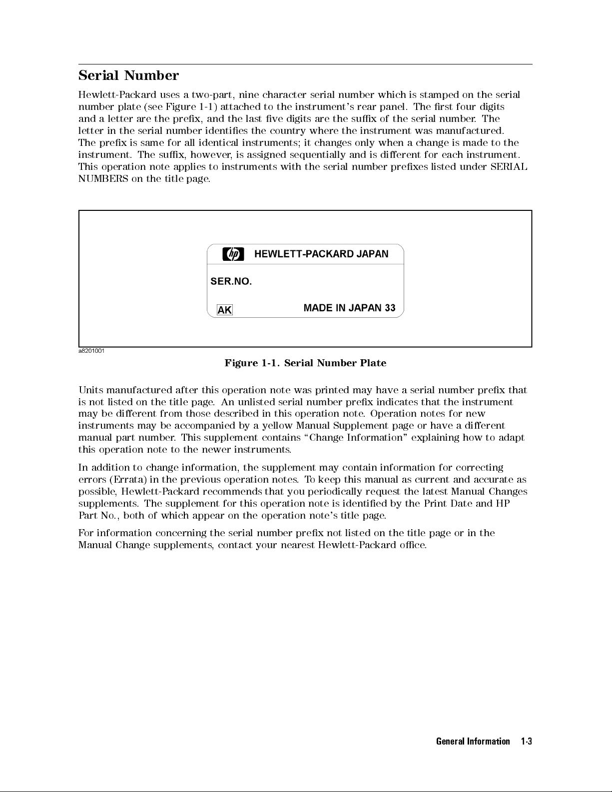
Hewlett-Packard uses a two-part, nine character serial number which is stamped on the serial
number plate (see Figure 1-1 ) attached to the instrument's rear panel. The rst four digits
and a letter are the prex, and the last ve digits are the sux of the serial number. The
letter in the serial number identies the country where the instrument was manufactured.
The prex is same for all identical instruments; it changes only when a change is made to the
instrument. The sux, however, is assigned sequentially and is dierent for each instrument.
This operation note applies to instruments with the serial number prexes listed under SERIAL
NUMBERS on the title page.
Figure 1-1. Serial Number Plate
Units manufactured after this operation note was printed may have a serial number prex that
is not listed on the title page. An unlisted serial number prex indicates that the instrument
may be dierent from those described in this operation note
instruments may be accompanied by a yellow Manual Supplement page or have a dierent
manual part number. This supplement contains \Change Information" explaining how to adapt
this operation note to the newer instruments.
In addition to change information, the supplement may contain information for correcting
errors (Errata) in the previous operation notes.To keep this manual as current and accurate as
possible, Hewlett-Packard recommends that you periodically request the latest Manual Changes
supplements. The supplement for this operation note is identied by the Print Date and HP
Part No., both of which appear on the operation note's title page.
For information concerning the serial number prex not listed on the title page or in the
Manual Change supplements, contact your nearest Hewlett-Packard oce.
. Operation notes for new
General Information 1-3
Page 12
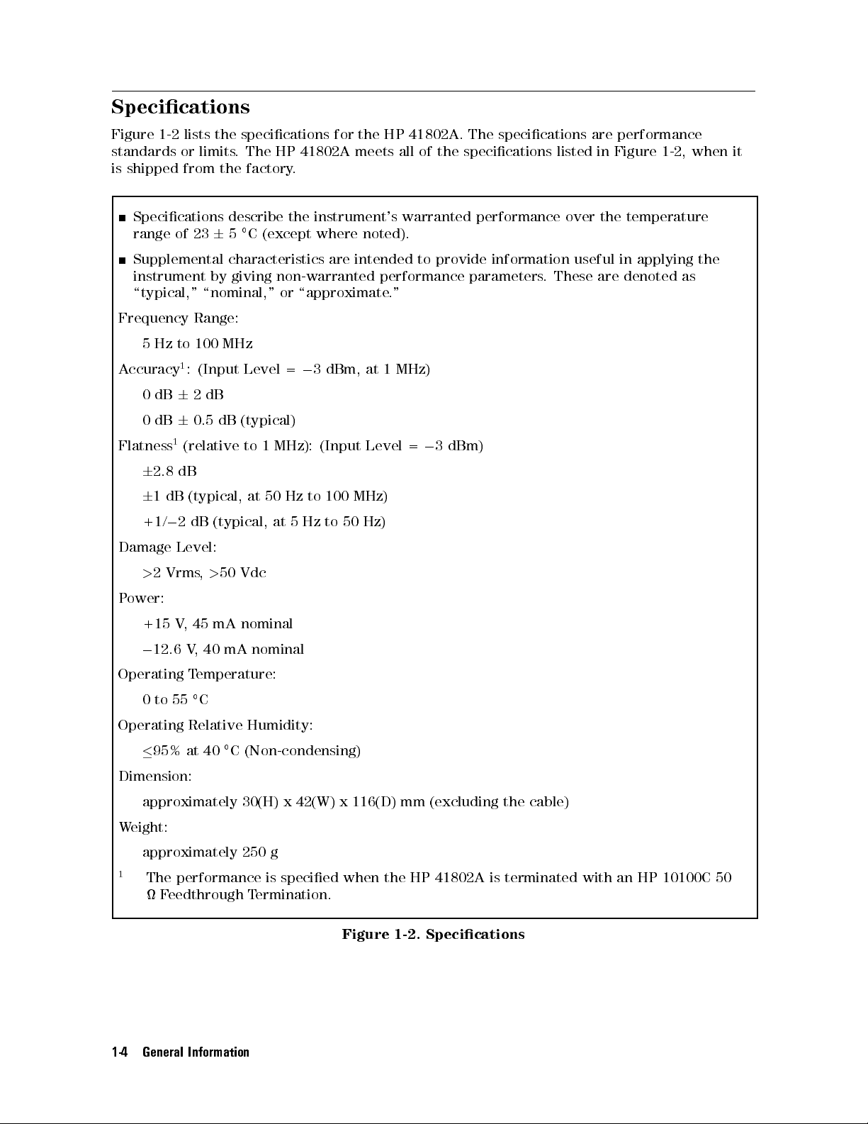
Specications
Figure 1-2 lists the specications for the HP 41802A. The specications are performance
standards or limits. The HP 41802A meets all of the specications listed in Figure 1-2, when it
is shipped from the factory.
Specications describe the instrument's warranted performance over the temperature
range of 2365C (except where noted).
Supplemental characteristics are intended to provide information useful in applying the
instrument by giving non-warranted performance parameters. These are denoted as
\typical," \nominal," or \approximate."
Frequency Range:
5 Hz to 100 MHz
Accuracy1: (Input Level =03 dBm, at 1 MHz)
0dB62dB
0dB60.5 dB (typical)
Flatness1(relative to 1 MHz): (Input Level =03 dBm)
6
2.8 dB
6
1 dB (typical, at 50 Hz to 100 MHz)
+1/02 dB (typical, at 5 Hz to 50 Hz)
Damage Level:
>
2 Vrms,>50 Vdc
Power:
+15 V, 45 mA nominal
0
12.6 V, 40 mA nominal
Operating Temperature:
0to55C
Operating Relative Humidity:
95% at 40C (Non-condensing)
Dimension:
approximately 30(H) x 42(W) x 116(D) mm (excluding the cable)
Weight:
approximately 250 g
1
The performance is specied when the HP 41802A is terminated with an HP 10100C 50
Feedthrough Termination.
1-4 General Information
Figure 1-2. Specications
Page 13
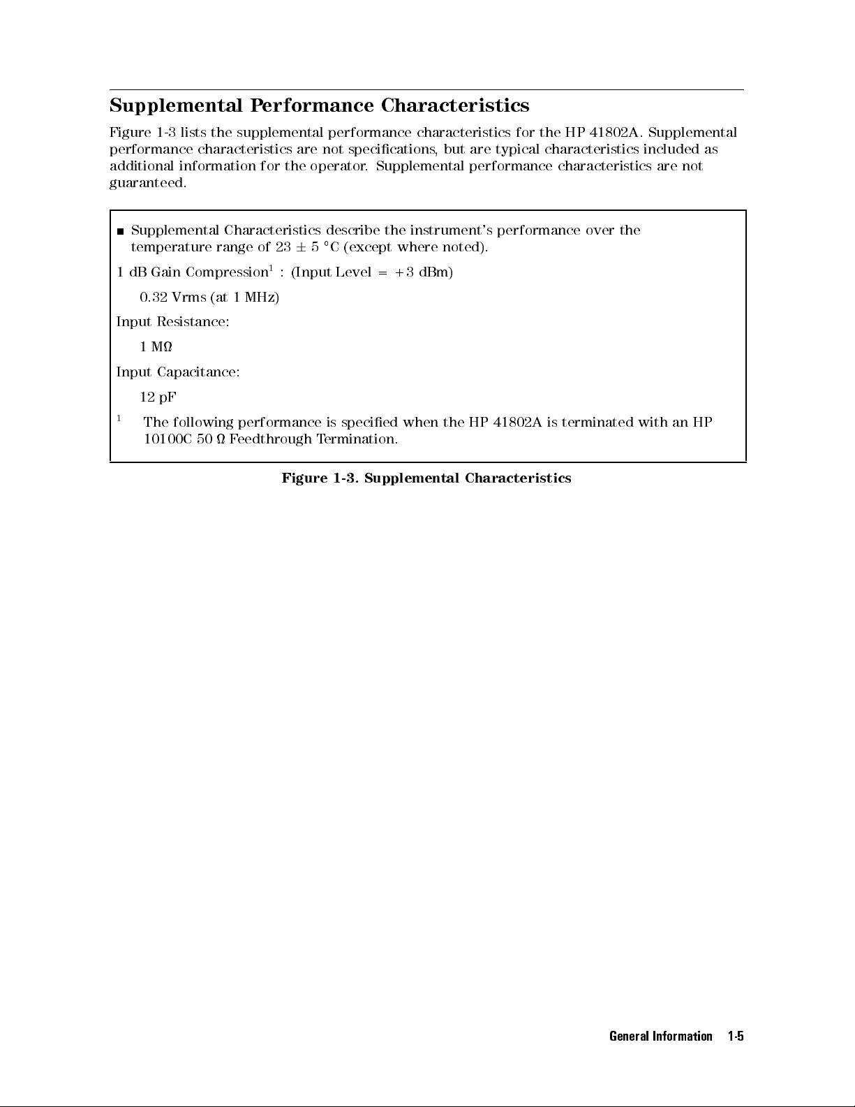
Supplemental Performance Characteristics
Figure 1-3 lists the supplemental performance characteristics for the HP 41802A. Supplemental
performance characteristics are not specications, but are typical characteristics included as
additional information for the operator. Supplemental performance characteristics are not
guaranteed.
Supplemental Characteristics describe the instrument's performance over the
temperature range of 2365C (except where noted).
1 dB Gain Compression1: (Input Level = +3 dBm)
0.32 Vrms (at 1 MHz)
Input Resistance:
1M
Input Capacitance:
12 pF
1
The following performance is specied when the HP 41802A is terminated with an HP
10100C 50 Feedthrough Termination.
Figure 1-3. Supplemental Characteristics
General Information 1-5
Page 14

Page 15
Installation
Introduction
This chapter contains the following information.
Initial inspection
Power Requirements
Mating connector
Environmental requirements
2
Installation 2-1
Page 16

Initial Inspection
Caution
The HP 41802A meets all of the specications listed in Figure 1-2. Upon receipt, inspect
the shipping container for damage. If the shipping container or the cushioning has been
damaged, keep the container and packing material until the contents have been checked
for completeness and the HP 41802A has been mechanically and electrically checked out.
Figure 2-1 shows the product overview of the HP 41802A. The procedures for checking the
general electrical operation are given in Chapter 4.
If anything is damaged (scratches, dents, broken connectors, etc.), or if performance does not
meet the specied performance test limits, notify the nearest HP sales oce (see the list at
the back of this operation note). The HP sales oce will immediately arrange for repair or
replacement without waiting for a claim settlement.
Electrostatic Discharge (ESD) can damage the HP 41802A's highly sensitive
input amplier.Do
the HP 41802A.
NOT
touch the center conductor of the BNC connector of
2-2 Installation
Figure 2-1. Product Overview
Page 17

Power Requirements
Power for the HP 41802A is supplied by the compatible instruments described in \Compatible
Instruments" in Chapter 1 by connecting the HP 41802A's power plug to the probe power jack
on the instrument. If the instrument used with the HP 41802A does not have a probe power
supply, use a separate power supply which meets the requirements listed in Table 2-1. The HP
1122A and HP 11899A Probe Power Supply meets these requirements and it accepts the HP
41802A's probe power plug directly.
Figure 2-2. Probe Power Requirements
Table 2-1. Probe Power Requirements
Pin Voltage Current
1012.6 V610% 40 mA
2 Ground
3 +15 V66% 45 mA
Mating Connectors
The output connector of the HP 41802A is a 50 N-type male connector
Note
Caution
Keep the N-type output connector clean.
Trying to mate this 50 N-type connector to a 75 N-type connector will
result in damage to both connectors.
.
Installation 2-3
Page 18

Environmental Requirements
The HP 41802A may be stored or shipped under the following environmental conditions.
Temperature:040C to +70C
Humidity:95% at 40C (Non-condensing)
The unit must be protected from temperature extremes which can cause condensation.
2-4 Installation
Page 19

Operation
Introduction
This chapter provides the following information.
Operating precautions
Preparation for use
Typical measurement setups
3
Operation 3-1
Page 20

Operating Precautions
This paragraph describes precautions for using the HP 41802A to prevent from damage on the
HP 41802A and your device under test (DUT).
Anti-static Precautions
Caution
The HP 41802A is sensitive to electrostatic discharge (ESD). The following must
be adhered to when using the HP 41802A.
Do
NOT
touch the center conductor of the BNC connector of the HP
41802A.
Do
NOT
touch the pin of the probe which is connected to the HP 41802A.
The probe input circuit is highly susceptible to damage by ESD introduced
through the input connector.
Eliminate ESD on your body.
Wear a snug-tting ground strap that is connected to earth ground through a
high resistance.Table 3-1 lists the available anti-static products.
Eliminate ESD on the work surface.
A grounded anti-static bench mat is recommended. Optional oor mats
provide an extra measure of protection, especially in areas with oor carpet.
Do
NOT
use the HP 41802A on a carpeted work surface
Do
NOT
introduce ESD into the DUT while the probe is in use
If an unprotected person touches a part of the DUT
.
.
, a static surge could
damage the DUT as well as the probe.
Table 3-1. Anti-static Products Available
Description HP Part Number
3-2 Operation
Liquid Anti-static Agent 8550-3397
Static Control Table Mat with Ground Cord 9300-0797
Small Wrist Strap with Ground Cord 9300-1099
Medium Wrist Strap with Ground Cord 9300-1117
Large Wrist Strap with Ground Cord 9300-1242
Page 21

Maximum Allowable Level
Caution
Discharging the Probe
Caution
Probe Power Plug
Note
Preparation for Use
Maximum allowable level (ac+dc) to the probe is650 V.
Measuring a node having a dc voltage potential charges the blocking capacitors
inside the HP 41802A. Ground the probe pin after measuring such nodes to
discharge probe capacitor.Failure to do this could result in damage to sensitive
circuits in the DUT, especially if it is an active device.
Connect the probe power plug, before connecting the N-type connector.
This paragraph provides the HP 41802A operating check procedure and the probe adjustment
procedure.
The HP 41802A operating check procedure checks the adapter gain using a network analyzer
a spectrum analyzer, or a network/spectrum analyzer. These operating check procedures are
only intended to ensure that the HP 41802A is functional. If the HP 41802A fails this check,
it should be repaired. To verify that the HP 41802A meets its specications
performance test described in Chapter 4.
The probe adjustment procedure is for frequency compensation. For the best measurement
results, always adjust the probe.
, perform the
,
Operation 3-3
Page 22

Operating Check Using a Network Analyzer
Using an HP 8751A or HP 3577A/B Network Analyzer
This section provides the HP 41802A operating check procedure using the HP 8751A or the HP
3577A/B network analyzer.
Equipment Required.
Network Analyzer: HP 8751A or HP 3577A/B
BNC(m)-BNC(m) Cable, 30 cm: PN 8120-1838
Adapters: as necessary
Procedure.
1. Connect the equipment as shown in Figure 3-1. Note that the probe power plug must be
connected before connecting the HP 41802A's N-type connector.
Figure 3-1. Operating Check Setup Using HP 8751A or HP 3577A/B Network Analyzer
2. Set the network analyzer as follows:
Measurement Mode: B(, A, or R) (absolute amplitude measurement)
Center Frequency: 1 MHz
Frequency Span: 0Hz
Output Level:
3. Conrm that the signal level is `04dB65dB.'
Note
3-4 Operation
If the signal level is lower than the limit, conrm that the power trip function
is set to OFF.
0
10 dBm
Page 23

Using HP 8753A/B/C Network Analyzer
This section provides the HP 41802A operating check procedure using the HP 8753A/B/C
network analyzer.
Equipment Required.
Network Analyzer: HP 8753A/B/C
50 Feedthrough: HP 10100C
BNC(m)-BNC(m) Cable, 30 cm: PN 8120-1838
Adapters: as necessary
Procedure.
1. Connect the equipment as shown in Figure 3-2. Note that the probe power plug must be
connected before connecting the HP 41802A's N-type connector.
Figure 3-2. Operating Check Setup Using HP 8753A/B/C Network Analyzer
2. Set the network analyzer as follows:
Measurement Mode: R (absolute amplitude measurement)
Center Frequency: 1 MHz
Frequency Span: 0Hz
Output Level:
3. Conrm that the signal level is `05dB65dB.'
Note
If the signal level is lower than the limit, conrm that the power trip function
is set to OFF.
0
5 dBm
Operation 3-5
Page 24

Operating Check Using a Spectrum Analyzer
This section provides the HP 41802A operating check procedure using a spectrum analyzer.
Equipment Required
Spectrum Analyzer: Any Compatible Spectrum Analyzer
BNC(m)-BNC(m) Cable, 61 cm: PN 8120-1839
50 Feedthrough: HP 10100C
Adapters: as necessary
Procedure
1. Connect the equipment as shown in Figure 3-3. Note that the probe power plug must be
connected before the HP 41802A's N-type connector.
Note
If the spectrum analyzer has a tracking generator output, use the tracking
generator output connector instead of the calibration output connector. Then
set the output level to010 dBm.
Figure 3-3. Operating Check Setup Using Spectrum Analyzer
2. Setup the spectrum analyzer as follows:
Center Frequency: Same as Calibration Output frequency.
Frequency Span: 0 Hz.
Attenuation: 40 dB.
3. Conrm that the signal level is `calibration output level
3-6 Operation
6
5dB.'
Page 25

Operating Check Using a Network/Spectrum Analyzer
This section provides the HP 41802A operating check procedure using the HP 4195A
network/spectrum analyzer.
Equipment Required
Network/Spectrum Analyzer: HP 4195A
BNC(m)-BNC(m) Cable, 30 cm: PN 8120-1838
Adapters: as necessary
Procedure
1. Connect the equipment as shown in Figure 3-4. Note that the probe power plug must be
connected before the HP 41802A's N-type connector.
Figure 3-4. Operating Check Setup Using Network/Spectrum Analyzer
2. Set up the Network/Spectrum analyzer as follows:
Conguration: Spectrum
Center Frequency: 1 MHz
Frequency Span: 0Hz
Port Select: Source Channel 1 on
Amplitude (S1):
Ref Attenuator (R1): 10 dB
3. Conrm that the signal level is `020 dB65dB.'
0
26 dBm
Operation 3-7
Page 26

Adjusting the Probe
Using a Network Analyzer
This section provides the probe adjustment procedure using a network analyzer.
Equipment Required.
Network Analyzer: Any Compatible Network Analyzer
Power Splitter: HP 11667A
N(m)-N(m) Adapter: PN 1250-0778
N(m)-BNC(m) Adapter: PN 1250-0780, 2 ea.
50 Feedthrough: HP 10100C
N(m)-N(m) Cable: HP 11500B
BNC(m)-BNC(m) Cable: PN 8120-1838
Procedure.
1. Connect the equipment as shown in Figure 3-5.
Figure 3-5. Probe Adjustment Setup Using a Network Analyzer|1
2. Setup the network analyzer as follows:
Measurement Mode: B/R
Start Frequency: 5Hz
Stop Frequency: 100 MHz
Sweep Type: Log Frequency
Source Power:
IF BW: 2Hz
3. Perform a response calibration.
3-8 Operation
0
5 dBm
Page 27

4. Change the connection as shown in Figure 3-6. Connect the ground lead rmly to provide
good electrical bond.
Figure 3-6. Probe Adjustment Setup Using a Network Analyzer|2
5. Touch the center pin of the feedthrough with the probe tip
.
6. Adjust the trimmer component (through opening in probe assembly cover) until the trace is
as close to020 dB as possible.
Note
Only the mid-frequency range is adjustable. (The low frequency and high
frequency range are not adjustable.) The adjustable range depends on the
probe you use.
Operation 3-9
Page 28

Using a Spectrum Analyzer
This section provides the probe adjustment procedure using a spectrum analyzer.
Equipment Required.
Spectrum Analyzer: Any Compatible Spectrum Analyzer
50 Feedthrough: HP 10100C
Adapters: as necessary
Procedure.
1. Connect the equipment as shown in Figure 3-7. Note that the probe power plug must be
connected before the HP 41802A's N-type connector. Connect the ground lead rmly to
provide good electrical bond.
Note
If the spectrum analyzer has a tracking generator output, use the tracking
generator output connector instead of the calibration output connector. Then
set the output level to010 dBm.
Figure 3-7. Probe Adjustment Setup Using Spectrum Analyzer
2. Setup the spectrum analyzer as follows:
Center Frequency: Same as Calibration Output frequency.
Frequency Span: 50 kHz.
Attenuation: 10 dB.
3. Touch the center conductor of the feedthrough with the probe tip.
4. Adjust the trimmer component (through opening in probe assembly cover) until the peak
0
signal level is as close to `calibration output level
3-10 Operation
20 dB' as possible.
Page 29

Typical Measurement Setups
This paragraph provides typical measurement setups using the HP 41802A. The following
setups are described.
Network Measurement Setups
Using one HP 41802A
Using one HP 41802A with a transmission/reection test set
Using two HP 41802As
Spectrum Measurement Setups
Using the HP 41802A with instruments which have BNC connectors
Caution
Note
Electrostatic discharge (ESD) can damage the HP 41802A's highly sensitive
input amplier.
Do
NOT
touch the center conductor of the BNC connector of the HP
41802A.
Do
NOT
touch the pin of the probe which is connected to the HP 41802A.
Do not apply a ac+dc level which exceeds650 V to the probe.
Do not mate the output connector of the probe assembly (50 type-N
connector) to 75 type-N connectors or damage may results
Connect the probe power plug before connecting the N-type connector
.
.
Operation 3-11
Page 30

Network Measurements
Using One HP 41802A
Figure 3-8 shows a typical measurement setup for the network measurements. Place the probe
tip as close to the input of the device under test, and perform a normalize (through) calibration
to compensate the frequency response error.
Figure 3-8. Network Measurement Setup Example (Using One HP 41802A)
3-12 Operation
Page 31

Using One HP 41802A with a Transmission/Reection Test Set
Figure 3-9 shows typical measurement setup for the network measurements using with a
transmission/reection test set. Place the probe tip as close to the input of the device under
test, and perform a normalize (through) calibration to compensate the frequency response
error.
Figure 3-9.
Network Measurement Setup Example (Using with a Transmission/Reection Set)
Operation 3-13
Page 32

Using Two HP 41802As
Figure 3-10 shows typical measurement setup for network measurements using two probes.
Place the probe tip as close as possible to the input of the device under test, and perform a
normalize (through) calibration to compensate the frequency response error.
Figure 3-10. Network Measurement Setup Example (Using Two HP 41802As)
Note
3-14 Operation
Use Input R and Input B to reduce cross talk.
If you want to set two HP 41802As side by side:
Set the HP 41802As vertically in the same direction.
Set the HP 41802As parallel and do not let them touch each other.
Page 33

Spectrum Measurements
Figure 3-11 shows typical measurement setup using a spectrum analyzer.
Figure 3-11. Spectrum Measurement Setup Example
Operation 3-15
Page 34

Using HP 41802A with instruments which have BNC connectors
Figure 3-12 shows typical measurement setup using a instrument which has a BNC input
connector. A BNC(m) cable and N(f)-BNC(m) adapter are recommended to use for connecting
the HP 41802A to the instrument. Do not use an inexible adapter such as a BNC(m)-N(f)
adapter instead of the cable and N(f)-BNC(f) adapter, otherwise the overweight caused by the
HP 41802A may damage the instrument's connector.
3-16 Operation
Figure 3-12. Measurement Setup Example (BNC input connector)
Page 35

Performance Test
Introduction
This chapter provides performance test procedure to ensure that the HP 41802A meets the
specications listed in Figure 1-2 . The performance test can be performed without accessing
the interior of the HP 41802A.
The test results should be recorded into the Performance Test Record which is located at the
end of this chapter.
Equipment Required
4
The equipment required for performance testing is listed in T
able 4-1 . Substitutions can
be made if the substitution equipment meets or exceeds the specications listed in the
Requirements column.
Table 4-1. Recommended Test Equipment
Equipment Critical Specications Recommended Model Qty.
Network Analyzer No substitute HP 8751A or HP
4195A
Power Splitter Frequency: 10 Hz to 100 MHz,
HP 11667A 1
Equivalent Output SWR:1.1
(@100 MHz)
Adapter 50 , N(m)-N(m) PN 1250-0778 1
50 , N(m)-BNC(f) PN 1250-0780 2
Attenuator Pad ATT 10 dB,
HP 8491A Opt. 010 1
Impedance 50 , N(m)-N(f)
ATT 20 dB, SWR:1.2,
HP 8491A Opt. 020 1
Impedance 50 , N(m)-N(f)
Cables 50 , N(m)-N(m) HP 11500B 1
50 , BNC(m)-BNC(m), 30cm PN 8120-1838 1
1
Coaxial Load 50 Feed through, BNC(m)-BNC(f),
VSWR:1.1 (@100 MHz)
HP 10100C 1
Performance Test 4-1
Page 36

Calibration Cycle
The HP 41802A requires periodic performance verication. The HP 41802A should be checked
out using the performance test at least once a year or more depending on its frequency of use.
Preparation
This paragraph provides the information which you should know and the steps that you should
perform before starting the performance test.
1. Allow the HP 41802A and the test equipment to warm up and stabilize for at least 30
minutes before you execute any of the performance tests.
2. Perform all performance tests in an ambient temperature of 23C65C.
4-2 Performance Test
Page 37

Gain Accuracy/Flatness Tests
Description
This test checks the gain at 1 MHz, and the atness (relative to 1 MHz).
Specications
Gain Accuracy: 0dB62 dB at 1 MHz
Flatness:
Test Equipment
Network Analyzer: HP 8751A
Power Splitter: HP 11667A
10 dB Attenuator Pad: HP 8491A Opt. 010
20 dB Attenuator Pad: HP 8491A Opt. 020
N(m)-N(m) Adapter: PN 1250-0778
N(m)-BNC(f) Adapter: PN 1250-0780, 2 ea.
50 Feed through: HP 10100C
N(m)-N(m) Cable: HP 11500B
BNC(m)-BNC(m) Cable: PN 8120-1838
Procedure
6
2.8 dB relative to 1 MHz
1. Connect the equipment as shown in Figure 4-1.
Figure 4-1. Test Setup 1
Performance Test 4-3
Page 38

2. Setup the HP 8751A as follows:
Control Settings Key Strokes
Preset
Start Freq. = 10 Hz
Stop Freq. = 100 MHz
Meas. Cong: B/R
Number of Points: 8
Sweep Type: LOG FREQ
IF BW = 2 Hz
Source Power = +3 dBm
Marker: Discrete
4
PRESET
4
START54154054x1
4
STOP54154054054M/
4
MEAS
4
MENU
4
MENU
4
AVG
4
MENU
4
MKR
5
NNNNNNNNNNN
5
B/R
NNNNNNNNNNNNNNNNNNNNNNNNNNNNNNNNNNNNNNNNNNNNNNNNNN
5
NUMBER of POINTS
NNNNNNNNNNNNNNNNNNNNNNNNNNNNNNNNNNNNNNNNNNNNNN
N
5
SWEEP TYPE MENU
NNNNNNNNNNNNNNNNN
5
IF BW
4254x15
NNNNNNNNNNNNNNNNN
5
POWER
NNNNNNNNNNNNNNNNNNNNNNNNNNNNNNNNNNNNNNNNNNNNNNNNNN
5
MARKER MODE MENU
4354x15
5
5
3. Perform the following key strokes to do a response calibration.
NNNNNNNNNNNNNNNNNNNNNNNNNNNNNNNNNNNNNNNNNNNN
4
5
CALIBRATE MENU
CAL
NNNNNNNNNNNNNNNNNNNNNNNNNN
RESPONSE
NNNNNNNNNNNNNN
THRU
NNNNNNNNNNNNNNNNNNNNNNNNNNNNNNNNNNNNNNNNN
DONE:RESPONSE
4. Change the connection as shown in Figure 4-2
4854x15
NNNNNNNNNNNNNNNNNNNNNNNNNN
LOG FREQ
NNNNNNNNNNNNNNNNNNNNNNNNNNNNNNNNNNNNNNNNNNNNNNNNNNNNN
MARKERS: DISCRETE
Figure 4-2. Test Setup 2
5. Perform the following key strokes for a single measurement.
4
MENU
NNNNNNNNNNNNNNNNNNNNNNNNNNNNNNNNNNNNN
N
TRIGGER MENU
5
NNNNNNNNNNNNNNNNNNNN
SINGLE
6. Rotate the RPG knob, and move the marker to the measurement result at 1 MHz. Record the
results on the Performance Test Record.
4-4 Performance Test
Page 39

7. Rotate the RPG knob, and move the marker according to the following table. Then record
the results on the Performance Test Record, and use the equation given on the Performance
Test Record to calculate the test results.
Test Frequency
10 Hz
100 Hz
1 kHz
10 kHz
100 kHz
10 MHz
100 MHz
Performance Test 4-5
Page 40

Performance Test Record
HP 41802A 1 M Input Adapter
Date:
Temperature:
Humidity:
Serial No.:
Tested by:
Gain Accuracy/Flatness Tests
Gain Accuracy (at 1 MHz, 0 dBm)
Minimum Limit Test Result
0
2.0 dB +2.0 dB
Flatness (relative to 0 dBm at 1 MHz)
Frequency Reading
Minimum
[b]
10 Hz
100 Hz
1 kHz
10 kHz
100 kHz
10 MHz
100 MHz
0
0
0
0
0
0
0
Maximum Limit Measurement
[a]
Limit
Test Result
[0a+b]
Maximum
Limit
2.8 dB +2.8 dB
2.8 dB +2.8 dB
2.8 dB +2.8 dB
2.8 dB +2.8 dB
2.8 dB +2.8 dB
2.8 dB +2.8 dB
2.8 dB +2.8 dB
Uncertainty
6
0.48 dB
Measurement
Uncertainty
6
0.70 dB
6
0.70 dB
6
0.70 dB
6
0.70 dB
6
0.70 dB
6
0.70 dB
6
0.70 dB
4-6 Performance Test
Page 41

5
Adjustment
Introduction
This chapter describes the adjustments required to return the HP 41802A to a condition to
meet the specications listed in Figure 1-2, if the HP 41802A failed the performance test, or
after it has been repaired. If proper performance cannot be achieved after these adjustments,
refer to Chapter 6.
Equipment Required
Table 4-1 lists the equipment required for adjustment.
Preparation
This paragraph provides the information which you should know
must perform before starting the adjustments.
1. Allow the HP 41802A and the test equipment to warm up and stabilize for at least 30
minutes before you execute the adjustments.
2. Perform the adjustments in an ambient temperature of 23
, and the procedures that you
C65
C.
Adjustment 5-1
Page 42

Gain Adjustment
Description
This adjustment adjust the HP 41802A's gain.
Equipment
Network Analyzer: HP 8751A
Power Splitter: HP 11667A
10 dB Attenuator Pad: HP 8491A Opt. 010
20 dB Attenuator Pad: HP 8491A Opt. 020
N(m)-N(m) Adapter: PN 1250-0778
N(m)-BNC(f) Adapter: PN 1250-0780, 2 ea.
50 Feed through: HP 10100C
N(m)-N(m) Cable: HP 11500B
BNC(m)-BNC(m) Cable: PN 8120-1838
Procedure
1. Remove the bottom plate of the HP 41802A.
2. Connect the equipment as shown in Figure 5-1.
5-2 Adjustment
Figure 5-1. Adjustment Setup 1
Page 43

3. Setup the HP 8751A as follows:
Control Settings Key Strokes
Preset
CENTER Freq. = 1 MHz
SPAN Freq. = 0 Hz
Meas. Cong: B/R
Number of Points: 2
IF BW = 200 Hz
Source Power = +3 dBm
Marker: Discrete
Scale: 0.1 dB/div
4
PRESET
4
CENTER54154M/
4
SPAN54054x1
4
MEAS
4
MENU
4
AVG
4
MENU
4
MKR
4
SCALE REF54.54154x1
5
5
NNNNNNNNNNN
5
B/R
NNNNNNNNNNNNNNNNNNNNNNNNNNNNNNNNNNNNNNNNNNNNNNNNNN
5
NUMBER of POINTS
NNNNNNNNNNNNNNNN
N
5
IF BW
4254054054x15
NNNNNNNNNNNNNNNNN
5
POWER
4354x15
NNNNNNNNNNNNNNNNNNNNNNNNNNNNNNNNNNNNNNNNNNNNNNNNNN
5
MARKER MODE MENU
5
5
4. Perform the following key strokes to do a response calibration.
NNNNNNNNNNNNNNNNNNNNNNNNNNNNNNNNNNNNNNNNNNNN
4
5
CALIBRATE MENU
CAL
NNNNNNNNNNNNNNNNNNNNNNNNNN
RESPONSE
NNNNNNNNNNNNNN
NNNNNNNNNNNNNNNNNNNNNNNNNNNNNNNNNNNNNNNNN
THRU
DONE:RESPONSE
5. Change the connection as shown in Figure 5-2.
4254x15
NNNNNNNNNNNNNNNNNNNNNNNNNNNNNNNNNNNNNNNNNNNNNNN
MARKER DESCRETE
Figure 5-2. Adjustment Setup 2
Adjustment 5-3
Page 44

6. Adjust A1R5 until the marker reading is 0 dB60.1 dB, and is as close as possible to 0 dB.
Figure 5-3. Adjustment Setup 3
5-4 Adjustment
Page 45

6
Replaceable Parts
This chapter provides information about the replaceable parts.
Replaceable Parts Lists
Accompanying each replaceable parts illustration is a replaceable parts list. Each list is
arranged in alpha-numerical order by reference designator. The reference designator keys the
part listed to the illustration. The rst part number listed is HP's part number and may dier
from the manufacturer's part number. The check digit serves as an error check of the part
number and should be used when ordering a part. Quantity refers to the quantity of the part
in the accompanying illustration. The description is a brief written description of the part and
may be used for ordering purposes. The manufacturer's code is a ve digit number assigned to
each manufacturer as listed in Table 6-1. The manufacturer part number may or may not be
the same as the HP part number.
Table 6-1. Component Manufactures
Mfr # Name Location Zipcode
28480 HEWLETT-PACKARD CO CORPORATE HQ PALO ALTO CA US 94304
78189 ILLINOIS TOOL WORKS INC SHAKEPROOF ELGIN IL US 60126
Replaceable Parts 6-1
Page 46

6-2 Replaceable Parts
Figure 6-1. Replaceable Parts (1 of 2)
Page 47

Table 6-2. Replaceable Parts (2 of 2)
RD Part No. CDQty. Description Mfr. Mfr.Part No.
1 41802-87112 9 1 LABEL 28480 41802-87112
2 2950-0035 8 1 NUT-HEX-DBL-CHAM 28480 2950-0035
3 41802-24003 5 1 SPACER 28480 41802-24003
4 2190-0102 8 1 WSHR-LK INTL T 78189 1922-01
5 41802-07001 7 1 KEEPER 28480 41802-07001
6 1250-1579 2 1 CONN-RF BNC 28480 1250-1579
7 41802-20001 5 1 HOUSING DIVIDER 28480 41802-20001
8 41802-66501 6 1 A1 HI Z ADAPTER 28480 41802-66501
9 41802-04001 1 1 COVER HOUSING 28480 41802-04001
10 0515-1873 0 2 SCREW METRIC 28480 0515-1873
11 5080-3324 2 1 LABEL (Serial No. Plate) 28480 5080-3324
12 0515-0976 2 3 SCR MACH M2X0.4 28480 0515-0976
13 2190-0654 5 3 WASHER LK HLCL 2 28480 2190-0654
14 41802-87113 0 1 LABEL 28480 41802-87113
15 0515-0914 8 2 SCR-MACH M3X0.5 28480 0515-0914
16 1250-2229 1 1 CONN N-PR-237 28480 1250-2229
17 0515-0914 8 2 SCR-MACH M3X0.5 28480 0515-0914
18 41802-87111 8 1 LABEL 28480 41802-87111
19 41802-61601 7 1 CABLE ASSY 28480 41802-61601
20 0515-1873 0 4 SCREW METRIC 28480 0515-1873
Replaceable Parts 6-3
Page 48

Figure 6-2. Replaceable Parts (2 of 2)
Table 6-3. Replaceable Parts (2 of 2)
RD Part No. CDQty. Description Mfr. Mfr.Part No.
1 41802-64901 6 1 HI Z ADAPTER (w/o Serial No. Plate) 28480 41802-64901
6-4 Replaceable Parts
Page 49

A
Manual Changes
Introduction
This appendix contains the information required to adapt this operation note to earlier
versions or congurations of the HP 41802A than the current printing date of this manual. The
information in this operation note applies directly to HP 41802A whose serial number prex is
listed on the title page of this operation note.
Manual Changes
To adapt this operation note to your HP 41802A, refer to T
changes listed opposite your instrument's serial number.
Instruments manufactured after the printing of this manual may be dierent than those
documented in this operation note. Later instrument versions will be documented in a manual
changes supplement that will accompany the operation note shipped with that instrument. If
your instrument serial number is not listed on the title page of this manual or in T
may be documented in a yellow
on serial number coverage, refer to \Serial Number" in Chapter 1.
Table A-1. Manual Changes by Serial Number
Serial Prex
or Number
There are no earlier congurations than the printing date of this operation note
MANUAL CHANGES
Make Manual Changes
able A-1, and make all of the manual
able A-1, it
supplement. For additional information
.
Manual Changes A-1
Page 50

 Loading...