

Page 1

User’s Guide
Volume 2
Measurement and Analysis
Agilent 4155B Semiconductor Parameter Analyzer
Agilent 4156B Precision Semiconductor Parameter Analyzer
Agilent Part No. 04156-90200
Printed in Japan May 2000
Edition 5
Page 2

Legal Notice
The information contained in this document is subject to change without notice.
Copyright © 1997, 2000 Agilent Technologies
This document contains information which is protected by copyright. All rights are
reserved. Reproduction, adaptation, or translation without prior written permission
is prohibited, except as allowed under the copyright laws.
• Product Warranty
Agilent Technologies warrants Agilent Technologies hardware, accessories and
supplies against defects in materials and workmanship for the period of one year
from the warranty start date specified below. If Agilent Technologies receives
notice of such defects during the warranty period, Agilent Technologies will, at
its option, either repair or replace products which prove to be defective.
Replacement products may be either new or like-new.
Warranty service of this product will be performed at Agilent Technologies.
Buyer shall prepay shipping charges to Agilent Technologies and Agilent
Technologies shall pay shipping charges to return the product to Buyer.
However, Buyer shall pay all shipping charges, duties, and taxes for products
returned to Agilent Technologies from another country.
Agilent Technologies does not warrant that the operation of Agilent
Technologies products will be uninterrupted or error free. If Agilent
Technologies is unable, within a reasonable time, to repair or replace any
product to a condition as warranted, customer will be entitled to a refund of the
purchase price upon prompt return of the product.
The Agilent Technologies products may contain remanufactured parts
equivalent to new in performance or may have been subject to incidental use.
The warranty period begins on the date of delivery or on the date of installation
if installed by Agilent Technologies. If customer schedules or delays Agilent
Technologies installation more than 30 days after delivery, warranty begins on
the 31st day from delivery.
Warranty does not apply to defects resulting from (a) improper or inadequate
maintenance or calibration, (b) software, interfacing, parts or supplies not
supplied by Agilent Technologies, (c) unauthorized modification or misuse, (d)
operation outside of the published environmental specifications for the product,
or (e) improper site preparation or maintenance.
2 Agilent 4155B/4156B User’s Guide Vol.2, Edition 5
Page 3

To the extent allowed by local law, the above warranties are exclusive and no
other warranty or condition, whether written or oral, is expressed or implied and
Agilent Technologies specifically disclaims any implied warranties or
conditions of merchantability, satisfactory quality, and fitness for a particular
purpose.
Agilent Technologies will be liable for damage to tangible property per incident
up to the greater of $300,000 or the actual amount paid for the product that is the
subject of the claim, and for damages for bodily injury or death, to the extent
that all such damages are determined by a court of competent jurisdiction to
have been directly caused by a defective Agilent Technologies product.
To the extent allowed by local law, the remedies in this warranty statement are
customer’s sole and exclusive remedies. Expect as indicated above, in no event
will Agilent Technologies or its suppliers be liable for loss of date or for direct,
special, incidental, consequential (including lost profit or date), or other damage,
whether based in contract, tort, or otherwise.
For consumer transactions in Australia and New Zealand: the warranty terms
contained in this statement, except to the extent lawfully permitted, do not
exclude, restrict or modify and are in addition to the mandatory statutory rights
applicable to the sale of this product to you.
• Assistance
Product maintenance agreements and other customer assistance agreements are
available for Agilent Technologies products.
For any assistance, contact your nearest Agilent Technologies Sales Office.
• Certification
Agilent Technologies, Inc. certifies that this product met its published
specifications at the time of shipment from the factory. Agilent Technologies
further certifies that its calibration measurements are traceable to the National
Institute of Standards and Technology (NIST), to the extent allowed by the
Institute’s calibration facility, and to the calibration facilities of other
International Standards Organization members.
Agilent 4155B/4156B User’s Guide Vol.2, Edition 5 3
Page 4

• Safety Summary
The following general safety precautions must be observed during all phases of
operation, service, and repair of this instrument. Failure to comply with these
precautions or with specific warnings elsewhere in this manual may impair the
protections provided by the equipment. In addition, it violates safety standards
of design, manufacture, and intended use of the instrument. Agilent
Technologies, Inc. assumes no liability for customer’s failure to comply with
these requirements.
NOTE Agilent 4155B/4156B/41501B comply with INSTALLATION CATEGORY II for
mains input and INSTALLATION CATEGORY I for measurement input terminals,
and POLLUTION DEGREE 2 defined in IEC 1010-1.
Agilent 4155B/4156B/41501B are INDOOR USE products.
NOTE LEDs in Agilent 4155B/4156B/41501B are Class 1 in accordance with IEC 825-1.
CLASS 1 LED PRODUCT.
• GROUND THE INSTRUMENT
This is Safety Class I instrument. To minimize shock hazard, the instrument
chassis and cabinet must be connected to an electrical ground. The power
terminal and the power cable must meet International Electrotechnical
Commission (IEC) safety standards.
• DO NOT OPERATE IN AN EXPLOSIVE ATMOSPHERE
Do not operate the instrument in the presence of flammable gases or fumes.
Operation of any electrical instrument in such an environment constitutes a
definite safety hazard.
• KEEP AWAY FROM LIVE CIRCUITS
Operation personnel must not remove instrument covers. Component
replacement and internal adjustments must be made by qualified
maintenance personnel. Do not replace components with power cable
connected. Under certain conditions, dangerous voltages may exist even
with the power cable removed. To avoid injuries, always disconnect power
and discharge circuits before touching them.
• DO NOT SERVICE OR ADJUST ALONE
Do not attempt internal service or adjustment unless another person, capable
of rendering first aid and resuscitation, is present.
4 Agilent 4155B/4156B User’s Guide Vol.2, Edition 5
Page 5

• DO NOT SUBSTITUTE PARTS OR MODIFY INSTRUMENT
Because of the danger of introducing additional hazards, do not install
substitute parts or perform any unauthorized modification to the instrument.
Return the instrument to a Agilent Technologies Sales and Service Office for
services and repair to ensure that safety features are maintained.
• DANGEROUS PROCEDURE WARNINGS
Warnings, such as example below, precede potentially dangerous procedures
throughout this manual. Instructions contained in the warnings must be
followed.
WARNING Dangerous Voltage, capable of causing death, are present in this instrument.
Use extreme caution when handling, testing, and adjusting.
• Safety Symbols
The general definitions of safety symbols used on equipment or in manuals are
listed below.
Instruction manual symbol: the product will be marked with this symbol when it
is necessary for the user to refer to the instruction manual in order to protect
against damage to the instrument.
Indicates dangerous voltage and potential for electrical shock. Do not touch
terminals that have this symbol when insrument is on.
Protective conductor terminal. For protection against electrical shock in case of
a fault. Used with field wiring terminals to indicate the terminal which must be
connected to ground before operating equipment.
Frame or chassis terminal. A connection to the frame (chassis) of the equipment
which normally includes all exposed metal structures.
Indicates earth (ground) terminal.
Alternating current.
Direct current.
ON (Supply).
Agilent 4155B/4156B User’s Guide Vol.2, Edition 5 5
Page 6

OFF (Supply).
STANDBY (Supply).
CAT 1
Means INSTALLATION CATEGORY I. Measurement terminals on the rear
panel comply with INSTALLATION CATEGORY I.
WARNING The warning sign denotes a hazard. It calls attention to a procedure, practice,
condition or the like, which, if not correctly performed or adhered to, could result in
injury or death to personal.
CAUTION The caution sign denotes a hazard. It calls attention to an operating procedure,
practice, condition or the like, which, if not correctly performed or adhered to, could
result in damage to or destruction of part or all of the product.
• Herstellerbescheinigung
GEÄUSCHEMISSION
Lpa < 70 dB
am Arbeitsplatz
normaler Betrieb
nach DIN 45635 T. 19
• Manufacturer’s Declaration
ACOUSTIC NOISE EMISSION
Lpa < 70dB
operator position
normal operation
per ISO 7779
6 Agilent 4155B/4156B User’s Guide Vol.2, Edition 5
Page 7

Printing History
Edition 1: August 1997
Edition 2: September 1997
Edition 3: October 1998
Edition 4: January 2000
Edition 5: May 2000
Agilent 4155B/4156B User’s Guide Vol.2, Edition 5 7
Page 8

In This Manual
This manual provides information for all parts and functions of Agilent
4155B/4156B, and consists of the following chapters:
• Measurement Units
This chapter provides information about the measurement units.
• Measurement Mode
This chapter provides information about sweep and sampling measurements.
• Measurement Functions
This chapter provides information about the measurement functions.
• Making a Measurement
This chapter describes how to perform measurements.
• Analyzing Measurement Results
This chapter describes how to analyze measurement results manually and
automatically.
• Screen Organization
This chapter provides information about each user interface that is displayed on
the instrument screen.
• Data Variable and Analysis Function
This chapter provides information about data variables and analysis functions.
• If You Have A Problem
This chapter provides problem-solving information that you may encounter.
Text Conventions
The following text conventions are used in this manual:
Screen Text Represents text that appears on screen of the 4155B/4156B.
Italic Refers to a related document, or is used for emphasis.
8 Agilent 4155B/4156B User’s Guide Vol.2, Edition 5
Page 9

Contents
1. Measurement Units
Ground Unit (GNDU) . . . . . . . . . . . . . . . . . . . . . . . . . . . . . . . . . . . . . . . . . . . . . . 1-3
Source/Monitor Unit (SMU) . . . . . . . . . . . . . . . . . . . . . . . . . . . . . . . . . . . . . . . . . 1-4
Voltage Source Unit (VSU) . . . . . . . . . . . . . . . . . . . . . . . . . . . . . . . . . . . . . . . . . 1-16
Voltage Monitor Unit (VMU) . . . . . . . . . . . . . . . . . . . . . . . . . . . . . . . . . . . . . . . 1-17
Pulse Generator Unit (PGU) . . . . . . . . . . . . . . . . . . . . . . . . . . . . . . . . . . . . . . . . 1-20
2. Measurement Mode
Sweep Measurement Mode . . . . . . . . . . . . . . . . . . . . . . . . . . . . . . . . . . . . . . . . . . 2-3
Basic Sweep Measurement . . . . . . . . . . . . . . . . . . . . . . . . . . . . . . . . . . . . . . . . 2-4
Subordinate Sweep Measurement . . . . . . . . . . . . . . . . . . . . . . . . . . . . . . . . . . . 2-7
Synchronous Sweep Measurement . . . . . . . . . . . . . . . . . . . . . . . . . . . . . . . . . . 2-9
Pulse Sweep Measurement . . . . . . . . . . . . . . . . . . . . . . . . . . . . . . . . . . . . . . . 2-11
Sampling Measurement Mode . . . . . . . . . . . . . . . . . . . . . . . . . . . . . . . . . . . . . . 2-14
Available Units. . . . . . . . . . . . . . . . . . . . . . . . . . . . . . . . . . . . . . . . . . . . . . . . . 2-14
Sampling Interval and Measurement Time . . . . . . . . . . . . . . . . . . . . . . . . . . . 2-15
Sampling Measurement Data . . . . . . . . . . . . . . . . . . . . . . . . . . . . . . . . . . . . . . 2-18
Sampling Completion . . . . . . . . . . . . . . . . . . . . . . . . . . . . . . . . . . . . . . . . . . . 2-20
Source Output Sequence and Time Origin . . . . . . . . . . . . . . . . . . . . . . . . . . . . 2-22
Linear Sampling Measurement . . . . . . . . . . . . . . . . . . . . . . . . . . . . . . . . . . . . 2-24
Thinned-out Sampling Measurement . . . . . . . . . . . . . . . . . . . . . . . . . . . . . . . 2-27
Logarithmic Sampling Measurement . . . . . . . . . . . . . . . . . . . . . . . . . . . . . . . 2-30
3. Measurement Functions
Stress Force Function . . . . . . . . . . . . . . . . . . . . . . . . . . . . . . . . . . . . . . . . . . . . . . 3-3
Stress Output Channels . . . . . . . . . . . . . . . . . . . . . . . . . . . . . . . . . . . . . . . . . . . 3-4
Stress Mode . . . . . . . . . . . . . . . . . . . . . . . . . . . . . . . . . . . . . . . . . . . . . . . . . . . . 3-6
Stress Force Sequence . . . . . . . . . . . . . . . . . . . . . . . . . . . . . . . . . . . . . . . . . . . . 3-7
Stress Stop Function at Abnormal Status . . . . . . . . . . . . . . . . . . . . . . . . . . . . 3-10
Agilent 4155B/4156B User’s Guide Vol.2, Edition 5 Contents - 1
Page 10

Contents
Knob Sweep Function . . . . . . . . . . . . . . . . . . . . . . . . . . . . . . . . . . . . . . . . . . . . 3-11
Available units and functions. . . . . . . . . . . . . . . . . . . . . . . . . . . . . . . . . . . . . . 3-11
Normal Sweep and Knob Sweep Measurements . . . . . . . . . . . . . . . . . . . . . . . 3-12
Features of Knob Sweep Function . . . . . . . . . . . . . . . . . . . . . . . . . . . . . . . . . 3-13
KNOB SWEEP screen . . . . . . . . . . . . . . . . . . . . . . . . . . . . . . . . . . . . . . . . . . 3-16
Y-AXIS ASSIGN Softkey . . . . . . . . . . . . . . . . . . . . . . . . . . . . . . . . . . . . . . . . 3-17
SETUP COPY Softkey . . . . . . . . . . . . . . . . . . . . . . . . . . . . . . . . . . . . . . . . . . 3-17
DISPLAY SETUP Softkey . . . . . . . . . . . . . . . . . . . . . . . . . . . . . . . . . . . . . . . 3-18
VAR1 SETUP Softkey . . . . . . . . . . . . . . . . . . . . . . . . . . . . . . . . . . . . . . . . . . . 3-20
VAR2 SETUP Softkey . . . . . . . . . . . . . . . . . . . . . . . . . . . . . . . . . . . . . . . . . . . 3-23
CONST SETUP Softkey . . . . . . . . . . . . . . . . . . . . . . . . . . . . . . . . . . . . . . . . . 3-25
Analysis of the Knob Sweep Measurement Results . . . . . . . . . . . . . . . . . . . . 3-26
Standby Function . . . . . . . . . . . . . . . . . . . . . . . . . . . . . . . . . . . . . . . . . . . . . . . . . 3-27
Standby Channels. . . . . . . . . . . . . . . . . . . . . . . . . . . . . . . . . . . . . . . . . . . . . . . 3-27
Standby State . . . . . . . . . . . . . . . . . . . . . . . . . . . . . . . . . . . . . . . . . . . . . . . . . . 3-27
Available Units and Output Values . . . . . . . . . . . . . . . . . . . . . . . . . . . . . . . . . 3-28
Output Values of non-Standby Channels . . . . . . . . . . . . . . . . . . . . . . . . . . . . . 3-28
Output Sequence of Standby Channels . . . . . . . . . . . . . . . . . . . . . . . . . . . . . . 3-29
When Getting Setup File . . . . . . . . . . . . . . . . . . . . . . . . . . . . . . . . . . . . . . . . . 3-30
Operation States . . . . . . . . . . . . . . . . . . . . . . . . . . . . . . . . . . . . . . . . . . . . . . . . . 3-31
Idle State. . . . . . . . . . . . . . . . . . . . . . . . . . . . . . . . . . . . . . . . . . . . . . . . . . . . . . 3-31
Measurement State . . . . . . . . . . . . . . . . . . . . . . . . . . . . . . . . . . . . . . . . . . . . . . 3-31
Stress Force State. . . . . . . . . . . . . . . . . . . . . . . . . . . . . . . . . . . . . . . . . . . . . . . 3-32
Standby State . . . . . . . . . . . . . . . . . . . . . . . . . . . . . . . . . . . . . . . . . . . . . . . . . . 3-32
Changing among Operation States . . . . . . . . . . . . . . . . . . . . . . . . . . . . . . . . . 3-32
Output Sequence . . . . . . . . . . . . . . . . . . . . . . . . . . . . . . . . . . . . . . . . . . . . . . . . . 3-34
Sequential Mode . . . . . . . . . . . . . . . . . . . . . . . . . . . . . . . . . . . . . . . . . . . . . . . 3-35
Simultaneous Mode . . . . . . . . . . . . . . . . . . . . . . . . . . . . . . . . . . . . . . . . . . . . . 3-37
Trigger Function . . . . . . . . . . . . . . . . . . . . . . . . . . . . . . . . . . . . . . . . . . . . . . . . . 3-39
Trigger Input . . . . . . . . . . . . . . . . . . . . . . . . . . . . . . . . . . . . . . . . . . . . . . . . . . 3-41
Contents - 2 Agilent 4155B/4156B User’s Guide Vol.2, Edition 5
Page 11

Contents
Trigger Output . . . . . . . . . . . . . . . . . . . . . . . . . . . . . . . . . . . . . . . . . . . . . . . . . 3-42
SMU/PG Selector Control . . . . . . . . . . . . . . . . . . . . . . . . . . . . . . . . . . . . . . . . . . 3-46
Setup and Switching Conditions . . . . . . . . . . . . . . . . . . . . . . . . . . . . . . . . . . . 3-47
Restrictions using Selector . . . . . . . . . . . . . . . . . . . . . . . . . . . . . . . . . . . . . . . . 3-47
R-BOX Control . . . . . . . . . . . . . . . . . . . . . . . . . . . . . . . . . . . . . . . . . . . . . . . . . . 3-48
Resistance Value . . . . . . . . . . . . . . . . . . . . . . . . . . . . . . . . . . . . . . . . . . . . . . . 3-48
Connections . . . . . . . . . . . . . . . . . . . . . . . . . . . . . . . . . . . . . . . . . . . . . . . . . . . 3-48
Setups . . . . . . . . . . . . . . . . . . . . . . . . . . . . . . . . . . . . . . . . . . . . . . . . . . . . . . . . 3-50
Circuit Diagram . . . . . . . . . . . . . . . . . . . . . . . . . . . . . . . . . . . . . . . . . . . . . . . . 3-51
Measurement Ranging Mode . . . . . . . . . . . . . . . . . . . . . . . . . . . . . . . . . . . . . . . 3-53
Auto Ranging . . . . . . . . . . . . . . . . . . . . . . . . . . . . . . . . . . . . . . . . . . . . . . . . . . 3-54
Limited Auto Ranging . . . . . . . . . . . . . . . . . . . . . . . . . . . . . . . . . . . . . . . . . . . 3-55
Compliance Range . . . . . . . . . . . . . . . . . . . . . . . . . . . . . . . . . . . . . . . . . . . . . . 3-56
Fixed Range . . . . . . . . . . . . . . . . . . . . . . . . . . . . . . . . . . . . . . . . . . . . . . . . . . . 3-56
Compliance . . . . . . . . . . . . . . . . . . . . . . . . . . . . . . . . . . . . . . . . . . . . . . . . . . . . . 3-57
Voltage and Current Compliance . . . . . . . . . . . . . . . . . . . . . . . . . . . . . . . . . . . 3-57
Power Compliance . . . . . . . . . . . . . . . . . . . . . . . . . . . . . . . . . . . . . . . . . . . . . . 3-61
Integration Time . . . . . . . . . . . . . . . . . . . . . . . . . . . . . . . . . . . . . . . . . . . . . . . . . 3-63
Short . . . . . . . . . . . . . . . . . . . . . . . . . . . . . . . . . . . . . . . . . . . . . . . . . . . . . . . . 3-63
Medium . . . . . . . . . . . . . . . . . . . . . . . . . . . . . . . . . . . . . . . . . . . . . . . . . . . . . . 3-64
Long . . . . . . . . . . . . . . . . . . . . . . . . . . . . . . . . . . . . . . . . . . . . . . . . . . . . . . . . . 3-64
SMU Filter . . . . . . . . . . . . . . . . . . . . . . . . . . . . . . . . . . . . . . . . . . . . . . . . . . . . . 3-65
Zero Offset Cancel . . . . . . . . . . . . . . . . . . . . . . . . . . . . . . . . . . . . . . . . . . . . . . . 3-66
To Measure Offset Data . . . . . . . . . . . . . . . . . . . . . . . . . . . . . . . . . . . . . . . . . . 3-66
To Perform Offset Cancel. . . . . . . . . . . . . . . . . . . . . . . . . . . . . . . . . . . . . . . . . 3-68
4. Making a Measurement
Connecting DUT . . . . . . . . . . . . . . . . . . . . . . . . . . . . . . . . . . . . . . . . . . . . . . . . . . 4-3
Using Test Fixture . . . . . . . . . . . . . . . . . . . . . . . . . . . . . . . . . . . . . . . . . . . . . . . 4-4
Agilent 4155B/4156B User’s Guide Vol.2, Edition 5 Contents - 3
Page 12

Contents
Using Connector Plate . . . . . . . . . . . . . . . . . . . . . . . . . . . . . . . . . . . . . . . . . . . . 4-6
Sweep Measurements . . . . . . . . . . . . . . . . . . . . . . . . . . . . . . . . . . . . . . . . . . . . . 4-10
To Define Measurement Units . . . . . . . . . . . . . . . . . . . . . . . . . . . . . . . . . . . . 4-12
To Set up Primary Sweep . . . . . . . . . . . . . . . . . . . . . . . . . . . . . . . . . . . . . . . . 4-14
To Set up Secondary Sweep . . . . . . . . . . . . . . . . . . . . . . . . . . . . . . . . . . . . . . 4-16
To Set up Synchronous Sweep . . . . . . . . . . . . . . . . . . . . . . . . . . . . . . . . . . . . 4-18
To Set up Constant Output . . . . . . . . . . . . . . . . . . . . . . . . . . . . . . . . . . . . . . . 4-20
To Set up SMU Pulsed Output . . . . . . . . . . . . . . . . . . . . . . . . . . . . . . . . . . . . 4-21
To Set up PGU Output . . . . . . . . . . . . . . . . . . . . . . . . . . . . . . . . . . . . . . . . . . 4-24
To Use Standby Function . . . . . . . . . . . . . . . . . . . . . . . . . . . . . . . . . . . . . . . . . 4-26
To Define a User Function . . . . . . . . . . . . . . . . . . . . . . . . . . . . . . . . . . . . . . . 4-27
To Display Graphics Results . . . . . . . . . . . . . . . . . . . . . . . . . . . . . . . . . . . . . . 4-28
To Display List Results . . . . . . . . . . . . . . . . . . . . . . . . . . . . . . . . . . . . . . . . . . 4-30
To Execute Calibration . . . . . . . . . . . . . . . . . . . . . . . . . . . . . . . . . . . . . . . . . . 4-31
To Use Offset Cancel Function . . . . . . . . . . . . . . . . . . . . . . . . . . . . . . . . . . . . 4-31
To Execute or Stop Measurement . . . . . . . . . . . . . . . . . . . . . . . . . . . . . . . . . . 4-32
To Use R-Box . . . . . . . . . . . . . . . . . . . . . . . . . . . . . . . . . . . . . . . . . . . . . . . . . 4-33
Knob Sweep Measurements . . . . . . . . . . . . . . . . . . . . . . . . . . . . . . . . . . . . . . . . 4-35
To Execute Knob Sweep Measurement . . . . . . . . . . . . . . . . . . . . . . . . . . . . . 4-36
To Stop Knob Sweep Measurement . . . . . . . . . . . . . . . . . . . . . . . . . . . . . . . . 4-39
Sampling Measurements . . . . . . . . . . . . . . . . . . . . . . . . . . . . . . . . . . . . . . . . . . . 4-40
To Define Measurement Units . . . . . . . . . . . . . . . . . . . . . . . . . . . . . . . . . . . . 4-42
To Set up Sampling Parameters . . . . . . . . . . . . . . . . . . . . . . . . . . . . . . . . . . . 4-44
To Set up Constant Output . . . . . . . . . . . . . . . . . . . . . . . . . . . . . . . . . . . . . . . 4-46
To Define Stop Conditions . . . . . . . . . . . . . . . . . . . . . . . . . . . . . . . . . . . . . . . 4-47
Stress Force . . . . . . . . . . . . . . . . . . . . . . . . . . . . . . . . . . . . . . . . . . . . . . . . . . . . . 4-49
To Set up Stress Source Channels . . . . . . . . . . . . . . . . . . . . . . . . . . . . . . . . . . 4-51
To Set up Stress Condition/Timing . . . . . . . . . . . . . . . . . . . . . . . . . . . . . . . . . 4-53
To Set up ac (Pulse) Output . . . . . . . . . . . . . . . . . . . . . . . . . . . . . . . . . . . . . . 4-55
To Set up dc Output . . . . . . . . . . . . . . . . . . . . . . . . . . . . . . . . . . . . . . . . . . . . . 4-57
Contents - 4 Agilent 4155B/4156B User’s Guide Vol.2, Edition 5
Page 13

Contents
To Force Stress . . . . . . . . . . . . . . . . . . . . . . . . . . . . . . . . . . . . . . . . . . . . . . . . 4-58
To Use Selector. . . . . . . . . . . . . . . . . . . . . . . . . . . . . . . . . . . . . . . . . . . . . . . . . 4-60
5. Analyzing Measurement Results
Manual Analysis . . . . . . . . . . . . . . . . . . . . . . . . . . . . . . . . . . . . . . . . . . . . . . . . . . 5-3
To Specify a Measurement Point on Curve . . . . . . . . . . . . . . . . . . . . . . . . . . . . 5-4
To Specify between Measurement Points on Curve . . . . . . . . . . . . . . . . . . . . . 5-6
To Display or Move Cursor . . . . . . . . . . . . . . . . . . . . . . . . . . . . . . . . . . . . . . . . 5-8
To Adjust Display Range to Measurement Curve Automatically . . . . . . . . . . . 5-9
To Zoom the Display Range . . . . . . . . . . . . . . . . . . . . . . . . . . . . . . . . . . . . . . . 5-9
To Center Display at Cursor Location . . . . . . . . . . . . . . . . . . . . . . . . . . . . . . . 5-10
To Draw Line through Two Specified Points . . . . . . . . . . . . . . . . . . . . . . . . . 5-10
To Draw Line through Specified Point with Specified Gradient . . . . . . . . . . 5-12
To Draw Tangent to Specified Point of Measurement Curve . . . . . . . . . . . . . 5-14
To Draw Regression Line for Specified Region . . . . . . . . . . . . . . . . . . . . . . . 5-16
To Display and Select a Line . . . . . . . . . . . . . . . . . . . . . . . . . . . . . . . . . . . . . . 5-18
To Display Grid on the Graph . . . . . . . . . . . . . . . . . . . . . . . . . . . . . . . . . . . . . 5-18
To Change Data Variable on Graph . . . . . . . . . . . . . . . . . . . . . . . . . . . . . . . . . 5-19
To Change Range of X or Y Axis Scale . . . . . . . . . . . . . . . . . . . . . . . . . . . . . 5-20
To Change Variable Assigned to X, Y1, or Y2 Axis . . . . . . . . . . . . . . . . . . . . 5-21
To Overlay an Internal Memory Measurement Curve onto Plotting Area . . . 5-22
To Scroll the LIST screen . . . . . . . . . . . . . . . . . . . . . . . . . . . . . . . . . . . . . . . . 5-24
To Display or Move Marker on LIST screen . . . . . . . . . . . . . . . . . . . . . . . . . 5-25
To Change Variables of LIST screen . . . . . . . . . . . . . . . . . . . . . . . . . . . . . . . . 5-26
Automatic Analysis . . . . . . . . . . . . . . . . . . . . . . . . . . . . . . . . . . . . . . . . . . . . . . . 5-27
To Draw Line by Specifying Two Points . . . . . . . . . . . . . . . . . . . . . . . . . . . . 5-28
To Draw Line by Specifying Gradient and One Point . . . . . . . . . . . . . . . . . . 5-30
To Draw Tangent to Specified Measurement Point . . . . . . . . . . . . . . . . . . . . . 5-32
To Draw Regression Line by Specifying Two Points . . . . . . . . . . . . . . . . . . . 5-34
To Display Marker at Specified Point . . . . . . . . . . . . . . . . . . . . . . . . . . . . . . . 5-37
Agilent 4155B/4156B User’s Guide Vol.2, Edition 5 Contents - 5
Page 14

Contents
6. Screen Organization
Screen Structure. . . . . . . . . . . . . . . . . . . . . . . . . . . . . . . . . . . . . . . . . . . . . . . . . . . 6-3
CHANNELS Screen Group . . . . . . . . . . . . . . . . . . . . . . . . . . . . . . . . . . . . . . . . . 6-5
CHANNELS: CHANNEL DEFINITION screen . . . . . . . . . . . . . . . . . . . . . . . 6-6
CHANNELS: USER FUNCTION DEFINITION screen . . . . . . . . . . . . . . . . 6-12
CHANNELS: USER VARIABLE DEFINITION screen . . . . . . . . . . . . . . . . 6-14
MEASURE Screen Group . . . . . . . . . . . . . . . . . . . . . . . . . . . . . . . . . . . . . . . . . 6-16
MEASURE: SWEEP SETUP screen . . . . . . . . . . . . . . . . . . . . . . . . . . . . . . . 6-17
MEASURE: SAMPLING SETUP screen . . . . . . . . . . . . . . . . . . . . . . . . . . . . 6-22
MEASURE: PGU SETUP screen . . . . . . . . . . . . . . . . . . . . . . . . . . . . . . . . . . 6-26
MEASURE: MEASURE SETUP screen . . . . . . . . . . . . . . . . . . . . . . . . . . . . 6-29
MEASURE: OUTPUT SEQUENCE screen . . . . . . . . . . . . . . . . . . . . . . . . . . 6-32
DISPLAY Screen Group . . . . . . . . . . . . . . . . . . . . . . . . . . . . . . . . . . . . . . . . . . . 6-35
DISPLAY: DISPLAY SETUP screen for graphic results . . . . . . . . . . . . . . . . 6-36
DISPLAY: DISPLAY SETUP screen for list results . . . . . . . . . . . . . . . . . . . 6-38
DISPLAY: ANALYSIS SETUP screen . . . . . . . . . . . . . . . . . . . . . . . . . . . . . . 6-40
GRAPH/LIST Screen Group . . . . . . . . . . . . . . . . . . . . . . . . . . . . . . . . . . . . . . . 6-46
On the GRAPHICS result screen . . . . . . . . . . . . . . . . . . . . . . . . . . . . . . . . . . . 6-46
On the LIST result screen . . . . . . . . . . . . . . . . . . . . . . . . . . . . . . . . . . . . . . . . 6-46
GRAPH/LIST: GRAPHICS screen . . . . . . . . . . . . . . . . . . . . . . . . . . . . . . . . . 6-47
GRAPH/LIST: LIST screen . . . . . . . . . . . . . . . . . . . . . . . . . . . . . . . . . . . . . . 6-62
STRESS Screen Group . . . . . . . . . . . . . . . . . . . . . . . . . . . . . . . . . . . . . . . . . . . . 6-74
STRESS: CHANNEL DEFINITION screen . . . . . . . . . . . . . . . . . . . . . . . . . 6-75
STRESS: STRESS SETUP screen . . . . . . . . . . . . . . . . . . . . . . . . . . . . . . . . . 6-79
STRESS: STRESS FORCE screen . . . . . . . . . . . . . . . . . . . . . . . . . . . . . . . . . 6-83
Screen Operation . . . . . . . . . . . . . . . . . . . . . . . . . . . . . . . . . . . . . . . . . . . . . . . . . 6-85
Data Input or Edit. . . . . . . . . . . . . . . . . . . . . . . . . . . . . . . . . . . . . . . . . . . . . . . 6-85
Blue front-panel key usage . . . . . . . . . . . . . . . . . . . . . . . . . . . . . . . . . . . . . . . 6-87
Green front-panel key usage . . . . . . . . . . . . . . . . . . . . . . . . . . . . . . . . . . . . . . 6-88
Contents - 6 Agilent 4155B/4156B User’s Guide Vol.2, Edition 5
Page 15

Contents
Edit front-panel keys . . . . . . . . . . . . . . . . . . . . . . . . . . . . . . . . . . . . . . . . . . . . 6-89
Status Indicators . . . . . . . . . . . . . . . . . . . . . . . . . . . . . . . . . . . . . . . . . . . . . . . . . 6-90
7. Data Variable and Analysis Function
Data Variable . . . . . . . . . . . . . . . . . . . . . . . . . . . . . . . . . . . . . . . . . . . . . . . . . . . . . 7-3
Data Variable for Output or Measurement Data . . . . . . . . . . . . . . . . . . . . . . . . 7-3
User Function . . . . . . . . . . . . . . . . . . . . . . . . . . . . . . . . . . . . . . . . . . . . . . . . . . 7-5
User Variable . . . . . . . . . . . . . . . . . . . . . . . . . . . . . . . . . . . . . . . . . . . . . . . . . . . 7-6
Syntax of Data Variable Name . . . . . . . . . . . . . . . . . . . . . . . . . . . . . . . . . . . . . 7-7
Expression . . . . . . . . . . . . . . . . . . . . . . . . . . . . . . . . . . . . . . . . . . . . . . . . . . . . . . . 7-8
Built-in Function . . . . . . . . . . . . . . . . . . . . . . . . . . . . . . . . . . . . . . . . . . . . . . . . . 7-11
ABS . . . . . . . . . . . . . . . . . . . . . . . . . . . . . . . . . . . . . . . . . . . . . . . . . . . . . . . . . 7-12
AT . . . . . . . . . . . . . . . . . . . . . . . . . . . . . . . . . . . . . . . . . . . . . . . . . . . . . . . . . . 7-12
AVG . . . . . . . . . . . . . . . . . . . . . . . . . . . . . . . . . . . . . . . . . . . . . . . . . . . . . . . . . 7-12
COND . . . . . . . . . . . . . . . . . . . . . . . . . . . . . . . . . . . . . . . . . . . . . . . . . . . . . . . 7-13
DELTA . . . . . . . . . . . . . . . . . . . . . . . . . . . . . . . . . . . . . . . . . . . . . . . . . . . . . . . 7-14
DIFF . . . . . . . . . . . . . . . . . . . . . . . . . . . . . . . . . . . . . . . . . . . . . . . . . . . . . . . . 7-15
EXP . . . . . . . . . . . . . . . . . . . . . . . . . . . . . . . . . . . . . . . . . . . . . . . . . . . . . . . . . 7-16
INTEG . . . . . . . . . . . . . . . . . . . . . . . . . . . . . . . . . . . . . . . . . . . . . . . . . . . . . . . 7-16
LGT . . . . . . . . . . . . . . . . . . . . . . . . . . . . . . . . . . . . . . . . . . . . . . . . . . . . . . . . . 7-17
LOG . . . . . . . . . . . . . . . . . . . . . . . . . . . . . . . . . . . . . . . . . . . . . . . . . . . . . . . . . 7-17
MAVG . . . . . . . . . . . . . . . . . . . . . . . . . . . . . . . . . . . . . . . . . . . . . . . . . . . . . . . 7-18
MAX . . . . . . . . . . . . . . . . . . . . . . . . . . . . . . . . . . . . . . . . . . . . . . . . . . . . . . . . 7-19
MIN . . . . . . . . . . . . . . . . . . . . . . . . . . . . . . . . . . . . . . . . . . . . . . . . . . . . . . . . . 7-19
SQRT . . . . . . . . . . . . . . . . . . . . . . . . . . . . . . . . . . . . . . . . . . . . . . . . . . . . . . . . 7-19
Read Out Function . . . . . . . . . . . . . . . . . . . . . . . . . . . . . . . . . . . . . . . . . . . . . . . 7-20
@CX . . . . . . . . . . . . . . . . . . . . . . . . . . . . . . . . . . . . . . . . . . . . . . . . . . . . . . . . 7-21
@CY . . . . . . . . . . . . . . . . . . . . . . . . . . . . . . . . . . . . . . . . . . . . . . . . . . . . . . . . 7-21
@CY1 . . . . . . . . . . . . . . . . . . . . . . . . . . . . . . . . . . . . . . . . . . . . . . . . . . . . . . . 7-21
@CY2 . . . . . . . . . . . . . . . . . . . . . . . . . . . . . . . . . . . . . . . . . . . . . . . . . . . . . . . 7-21
Agilent 4155B/4156B User’s Guide Vol.2, Edition 5 Contents - 7
Page 16

Contents
@IX . . . . . . . . . . . . . . . . . . . . . . . . . . . . . . . . . . . . . . . . . . . . . . . . . . . . . . . . . 7-22
@IY . . . . . . . . . . . . . . . . . . . . . . . . . . . . . . . . . . . . . . . . . . . . . . . . . . . . . . . . . 7-22
@IY1 . . . . . . . . . . . . . . . . . . . . . . . . . . . . . . . . . . . . . . . . . . . . . . . . . . . . . . . . 7-23
@IY2 . . . . . . . . . . . . . . . . . . . . . . . . . . . . . . . . . . . . . . . . . . . . . . . . . . . . . . . . 7-23
@L1CO . . . . . . . . . . . . . . . . . . . . . . . . . . . . . . . . . . . . . . . . . . . . . . . . . . . . . . 7-24
@L1G . . . . . . . . . . . . . . . . . . . . . . . . . . . . . . . . . . . . . . . . . . . . . . . . . . . . . . . 7-24
@L1G1 . . . . . . . . . . . . . . . . . . . . . . . . . . . . . . . . . . . . . . . . . . . . . . . . . . . . . . 7-25
@L1G2 . . . . . . . . . . . . . . . . . . . . . . . . . . . . . . . . . . . . . . . . . . . . . . . . . . . . . . 7-26
@L1X . . . . . . . . . . . . . . . . . . . . . . . . . . . . . . . . . . . . . . . . . . . . . . . . . . . . . . . 7-27
@L1Y . . . . . . . . . . . . . . . . . . . . . . . . . . . . . . . . . . . . . . . . . . . . . . . . . . . . . . . 7-27
@L1Y1 . . . . . . . . . . . . . . . . . . . . . . . . . . . . . . . . . . . . . . . . . . . . . . . . . . . . . . 7-27
@L1Y2 . . . . . . . . . . . . . . . . . . . . . . . . . . . . . . . . . . . . . . . . . . . . . . . . . . . . . . 7-27
@L2CO . . . . . . . . . . . . . . . . . . . . . . . . . . . . . . . . . . . . . . . . . . . . . . . . . . . . . . 7-27
@L2G . . . . . . . . . . . . . . . . . . . . . . . . . . . . . . . . . . . . . . . . . . . . . . . . . . . . . . . 7-28
@L2G1 . . . . . . . . . . . . . . . . . . . . . . . . . . . . . . . . . . . . . . . . . . . . . . . . . . . . . . 7-29
@L2G2 . . . . . . . . . . . . . . . . . . . . . . . . . . . . . . . . . . . . . . . . . . . . . . . . . . . . . . 7-30
@L2X . . . . . . . . . . . . . . . . . . . . . . . . . . . . . . . . . . . . . . . . . . . . . . . . . . . . . . . 7-31
@L2Y . . . . . . . . . . . . . . . . . . . . . . . . . . . . . . . . . . . . . . . . . . . . . . . . . . . . . . . 7-31
@L2Y1 . . . . . . . . . . . . . . . . . . . . . . . . . . . . . . . . . . . . . . . . . . . . . . . . . . . . . . 7-31
@L2Y2 . . . . . . . . . . . . . . . . . . . . . . . . . . . . . . . . . . . . . . . . . . . . . . . . . . . . . . 7-31
@MI . . . . . . . . . . . . . . . . . . . . . . . . . . . . . . . . . . . . . . . . . . . . . . . . . . . . . . . . 7-31
@MX . . . . . . . . . . . . . . . . . . . . . . . . . . . . . . . . . . . . . . . . . . . . . . . . . . . . . . . . 7-32
@MY . . . . . . . . . . . . . . . . . . . . . . . . . . . . . . . . . . . . . . . . . . . . . . . . . . . . . . . . 7-32
@MY1 . . . . . . . . . . . . . . . . . . . . . . . . . . . . . . . . . . . . . . . . . . . . . . . . . . . . . . . 7-32
@MY2 . . . . . . . . . . . . . . . . . . . . . . . . . . . . . . . . . . . . . . . . . . . . . . . . . . . . . . . 7-32
Analysis Function . . . . . . . . . . . . . . . . . . . . . . . . . . . . . . . . . . . . . . . . . . . . . . . . 7-33
Marker on the GRAPH/LIST: GRAPHICS screen . . . . . . . . . . . . . . . . . . . . . 7-34
Marker on the GRAPH/LIST: LIST screen . . . . . . . . . . . . . . . . . . . . . . . . . . 7-36
Cursor . . . . . . . . . . . . . . . . . . . . . . . . . . . . . . . . . . . . . . . . . . . . . . . . . . . . . . . 7-38
Line Drawing . . . . . . . . . . . . . . . . . . . . . . . . . . . . . . . . . . . . . . . . . . . . . . . . . 7-39
Scaling Functions . . . . . . . . . . . . . . . . . . . . . . . . . . . . . . . . . . . . . . . . . . . . . . 7-41
Contents - 8 Agilent 4155B/4156B User’s Guide Vol.2, Edition 5
Page 17

Contents
Overlay Display Function . . . . . . . . . . . . . . . . . . . . . . . . . . . . . . . . . . . . . . . . 7-42
Automatic Analysis Function . . . . . . . . . . . . . . . . . . . . . . . . . . . . . . . . . . . . . 7-42
8. If You Have A Problem
When You Make A Measurement . . . . . . . . . . . . . . . . . . . . . . . . . . . . . . . . . . . . . 8-4
If Measured Value Oscillates when Measuring High-Frequency Devices . . . . 8-5
If Measured Value Oscillates when Measuring Negative Resistance . . . . . . . . 8-6
If Noise Affects the Measured Values . . . . . . . . . . . . . . . . . . . . . . . . . . . . . . . . 8-7
If Measured Voltage has some Error when Forcing a Large Current . . . . . . . . 8-8
If Large Current Causes High Temperature (Thermal Drift) . . . . . . . . . . . . . . 8-8
If Measurement Takes More Time than Specified . . . . . . . . . . . . . . . . . . . . . . 8-9
If Measurement Damages the Device under Test . . . . . . . . . . . . . . . . . . . . . . 8-10
If You Get Unexpected Data when Performing Sampling Measurement . . . . 8-12
If Errors Occur . . . . . . . . . . . . . . . . . . . . . . . . . . . . . . . . . . . . . . . . . . . . . . . . . . 8-13
If Errors Occur when You Perform Self-calibration or Diagnostics . . . . . . . . 8-14
If Errors Occur when You Operate the 4155B/4156B . . . . . . . . . . . . . . . . . . 8-20
If a Measurement Data Status is Displayed . . . . . . . . . . . . . . . . . . . . . . . . . . . 8-38
Agilent 4155B/4156B User’s Guide Vol.2, Edition 5 Contents - 9
Page 18

Contents
Contents - 10 Agilent 4155B/4156B User’s Guide Vol.2, Edition 5
Page 19

1 Measurement Units
Agilent 4155B/4156B User’s Guide Vol.2, Edition 5
Page 20

Measurement Units
This chapter explains basic output and measurement functions of each measurement
unit. For the following units, a simplified circuit diagram is shown, and where
applicable, the output and measurement ranges are provided.
•“Ground Unit (GNDU)”
•“Source/Monitor Unit (SMU)”
•“Voltage Source Unit (VSU)”
•“Voltage Monitor Unit (VMU)”
•“Pulse Generator Unit (PGU)”
1-2 Agilent 4155B/4156B User’s Guide Vol.2, Edition 5
Page 21

Ground Unit (GNDU)
The ground unit (GNDU) is in Agilent 41501A/B (SMU and pulse generator
expander). The GNDU is a 0 V constant source that provides a measurement ground
reference, and can sink up to ±1.6 A. Figure 1-1 shows a simplified GNDU circuit
diagram.
Figure 1-1 Simplified GNDU Circuit Diagram
Measurement Units
Ground Unit (GNDU)
Agilent 4155B/4156B User’s Guide Vol.2, Edition 5 1-3
Page 22

Measurement Units
Source/Monitor Unit (SMU)
Source/Monitor Unit (SMU)
The source/monitor unit (SMU) has the following three modes:
• voltage source and current monitor mode (V source and I monitor mode)
• current source and voltage monitor mode (I source and V monitor mode)
• source common mode
SMU can output constant or pulsed source. (Only one SMU can be set to pulsed
source.)
Figure 1-2 shows a simplified SMU circuit diagram.
Figure 1-2 Simplified SMU Circuit Diagram
1-4 Agilent 4155B/4156B User’s Guide Vol.2, Edition 5
Page 23

Measurement Units
Source/Monitor Unit (SMU)
Three types of SMUs are available:
• HRSMU (high resolution SMU)
• Force and measure: up to ±100 V or ±100 mA.
• Maximum output power: 2 W.
• Minimum current measurement range: 10 pA with 1 fA resolution.
• Only the 4156B has HRSMUs. The 4156B has four HRSMUs.
• MPSMU (medium power SMU)
• Force and measure: up to ±100 V or ±100 mA.
• Maximum output power: 2 W.
• The 4155B has four MPSMUs, and the 41501A/B can be equipped with
either two MPSMUs or one HPSMU.
• HPSMU (high power SMU)
• Force and measure: up to ±200 V or ±1 A.
• Maximum output power: 20 W.
• Only the 41501A/B has HPSMU. The 41501A/B can be equipped with
either two MPSMUs or one HPSMU.
HPSMUs and HRSMUs can be connected to test devices by Kelvin connection.
Each SMU has a compliance feature that limits output voltage or current to prevent
damage to your devices. When the SMU forces voltage, you can specify I
compliance. When the SMU forces current, you can specify V compliance.
For details about the compliance setting range and resolution, see “Compliance” in
Chapter 3.
The following figures and tables show the output and measurement ranges of each
SMU type.
Agilent 4155B/4156B User’s Guide Vol.2, Edition 5 1-5
Page 24

Measurement Units
Source/Monitor Unit (SMU)
Figure 1-3 HRSMU Output and Measurement Ranges
Table 1-1 HRSMU Output Voltage Ranges and Resolutions
Range Output Value
2 V 0 £ ½V½ £ 2 V 100 mV ±100 mA
20 V 0 £ ½V½ £ 20 V 1 mV ±100 mA
40 V 0 £ ½V½ £ 40 V 2 mV ±50 mA
100 V 0 £ ½V½ £ 100 V 5 mV ±20 mA
1-6 Agilent 4155B/4156B User’s Guide Vol.2, Edition 5
Output
Resolution
Current
Compliance
Range
Page 25

Measurement Units
Source/Monitor Unit (SMU)
Table 1-2 HRSMU Measurement Voltage Values and Resolutions
b
Measurement Resolutions
Range
2 V 0 £ ½V½ £ 2.2 V 2 mV20 mV200 mV2 mV
20 V 0 £ ½V½ £ 22 V 20 mV200 mV 2 mV 20 mV
40 V 0 £ ½V½ £ 44 V 40 mV400 mV 4 mV 40 mV
100 V 0 £ ½V½ £ 100 V 100 mV 1 mV 10 mV 100 mV
a. This column is applied to the auto ranging or the limited auto ranging. For fixed ranging, maximum mea-
surement value is Range column value.
b. Measurement resolution depends on the integration time setting. For Knob sweep measurement, see the
column of Integration Time 80 ms to 560 ms.
c. This column is applied to the sampling measurement that initial interval is set to 480 ms or shorter.
Measurement
Value
a
1PLC or
Longer
Integration Time
640 ms to 1.92
ms
80 ms to 560 ms
High Speed
Sampling
Measurement
Table 1-3 HRSMU Output Current Ranges and Resolutions
c
Voltage
Compliance
Range
±100 V
±100 V
±100 V
±100 V
±100 V
±100 V
±100 V
±100 V
±100 V
±100 V
±100 V
±40 V
±20 V
Range Output Value
10 pA
100 pA
1 nA
10 nA
100 nA
1 mA
10 mA
100 mA
1 mA
10 mA 0 £ ½I½ £ 10 mA 1 mA
100 mA 0 £ ½I½ £ 20 mA 10 mA
£ ½I½ £ 10 pA
0
£ ½I½ £ 100 pA
0
£ ½I½ £ 1 nA
0
0
£ ½I½ £ 10 nA
£ ½I½ £ 100 nA
0
£ ½I½ £ 1 mA
0
0
£ ½I½ £ 10 mA
£ ½I½ £ 100 mA
0
£ ½I½ £ 1 mA
0
20 mA < ½I½ £ 50 mA 10 mA
50 mA < ½I½ £ 100 mA 10 mA
Resolution
10 fA
10 fA
100 fA
1 pA
10 pA
100 pA
1 nA
10 nA
100 nA
Output
Agilent 4155B/4156B User’s Guide Vol.2, Edition 5 1-7
Page 26

Measurement Units
Source/Monitor Unit (SMU)
Table 1-4 HRSMU Measurement Current Values and Resolutions
Measurement Resolutions
Range
10 pA
100 pA
1 nA
10 nA
100 nA
1 mA
10 mA
100 mA
1 mA
10 mA
100 mA
Measurement
£ ½I½ £ 10.5 pA
0
£ ½I½ £ 115 pA
0
0
£ ½I½ £ 1.15 nA
0
£ ½I½ £ 11.5 nA
£ ½I½ £ 115 nA
0
0
£ ½I½ £ 1.15 mA
0
£ ½I½ £ 11.5 mA
£ ½I½ £ 115 mA
0
0
£ ½I½ £ 1.15 mA
0
£ ½I½ £ 11.5 mA
£ ½I½ £ 100 mA
0
Value
a
1PLC or
Longer
1 fA 1 fA 1 fA 10 fA
1 fA 1 fA 10 fA 100 fA
10 fA 10 fA 100 fA 1 pA
10 fA 100 fA 1 pA 10 pA
100 fA 1 pA 10 pA 100 pA
1 pA 10 pA 100 pA 1 nA
10 pA 100 pA 1 nA 10 nA
100 pA 1 nA 10 nA 100 nA
1 nA 10 nA 100 nA 1 mA
10 nA 100 nA 1 mA10 mA
100 nA 1 mA10 mA100 mA
Integration Time
640 ms to 1.92
ms
80 ms to 560 ms
b
High Speed
Sampling
Measurement
c
a. This column is applied to the auto ranging or the limited auto ranging. For fixed ranging, maximum mea-
surement value is Range column value.
b. Measurement resolution depends on the integration time setting. For Knob sweep measurement, see the
column of Integration Time 80 ms to 560 ms.
c. This column is applied to the sampling measurement that initial interval is set to 480 ms or shorter.
1-8 Agilent 4155B/4156B User’s Guide Vol.2, Edition 5
Page 27

Figure 1-4 MPSMU Output and Measurement Ranges
Measurement Units
Source/Monitor Unit (SMU)
Table 1-5 MPSMU Output Voltage Ranges and Resolutions
Range Output Value
2 V 0 £ ½V½ £ 2 V 100 mV ±100 mA
20 V 0 £ ½V½ £ 20 V 1 mV ±100 mA
40 V 0 £ ½V½ £ 40 V 2 mV ±50 mA
100 V 0 £ ½V½ £ 100 V 5 mV ±20 mA
Agilent 4155B/4156B User’s Guide Vol.2, Edition 5 1-9
Output
Resolution
Current
Compliance
Range
Page 28

Measurement Units
Source/Monitor Unit (SMU)
Table 1-6 MPSMU Measurement Voltage Values and Resolutions
b
Measurement Resolutions
Range
2 V 0 £ ½V½ £ 2.2 V 2 mV20 mV200 mV2 mV
20 V 0 £ ½V½ £ 22 V 20 mV200 mV 2 mV 20 mV
40 V 0 £ ½V½ £ 44 V 40 mV400 mV 4 mV 40 mV
100 V 0 £ ½V½ £ 100 V 100 mV 1 mV 10 mV 100 mV
a. This column is applied to the auto ranging or the limited auto ranging. For fixed ranging, maximum mea-
surement value is Range column value.
b. Measurement resolution depends on the integration time setting. For Knob sweep measurement, see the
column of Integration Time 80 ms to 560 ms.
c. This column is applied to the sampling measurement that initial interval is set to 480 ms or shorter.
Measurement
Value
a
1PLC or
Longer
Integration Time
640 ms to 1.92
ms
80 ms to 560 ms
High Speed
Sampling
Measurement
Table 1-7 MPSMU Output Current Ranges and Resolutions
c
Voltage
Compliance
Range
±100 V
±100 V
±100 V
±100 V
±100 V
±100 V
±100 V
±100 V
±100 V
±40 V
±20 V
Range Output Value
1 nA
10 nA
100 nA
1 mA
10 mA
100 mA
1 mA
10 mA 0 £ ½I½ £ 10 mA 1 mA
100 mA 0 £ ½I½ £ 20 mA 10 mA
£ ½I½ £ 1 nA
0
£ ½I½ £ 10 nA
0
£ ½I½ £ 100 nA
0
0
£ ½I½ £ 1 mA
£ ½I½ £ 10 mA
0
£ ½I½ £ 100 mA
0
0
£ ½I½ £ 1 mA
20 mA < ½I½ £ 50 mA 10 mA
50 mA < ½I½ £ 100 mA 10 mA
Resolution
100 fA
1 pA
10 pA
100 pA
1 nA
10 nA
100 nA
Output
1-10 Agilent 4155B/4156B User’s Guide Vol.2, Edition 5
Page 29

Measurement Units
Source/Monitor Unit (SMU)
Table 1-8 MPSMU Measurement Current Values and Resolutions
b
Measurement Resolutions
Range
1 nA
10 nA
100 nA
1 mA
10 mA
100 mA
1 mA
10 mA
100 mA
a. This column is applied to the auto ranging or the limited auto ranging. For fixed ranging, maximum mea-
surement value is Range column value.
b. Measurement resolution depends on the integration time setting. For Knob sweep measurement, see the
column of Integration Time 80 ms to 560 ms.
c. This column is applied to the sampling measurement that initial interval is set to 480 ms or shorter.
Measurement
0 £ ½I½ £ 1.15 nA
£ ½I½ £ 11.5 nA
0
0
£ ½I½ £ 115 nA
0
£ ½I½ £ 1.15 mA
£ ½I½ £ 11.5 mA
0
0
£ ½I½ £ 115 mA
0
£ ½I½ £ 1.15 mA
£ ½I½ £ 11.5 mA
0
0
£ ½I½ £ 100 mA
Value
a
1PLC or
Longer
10 fA 10 fA 100 fA 1 pA
10 fA 100 fA 1 pA 10 pA
100 fA 1 pA 10 pA 100 pA
1 pA 10 pA 100 pA 1 nA
10 pA 100 pA 1 nA 10 nA
100 pA 1 nA 10 nA 100 nA
1 nA 10 nA 100 nA 1 mA
10 nA 100 nA 1 mA10 mA
100 nA 1 mA10 mA100 mA
Integration Time
640 ms to 1.92
ms
80 ms to 560 ms
High Speed
Sampling
Measurement
c
Agilent 4155B/4156B User’s Guide Vol.2, Edition 5 1-11
Page 30

Measurement Units
Source/Monitor Unit (SMU)
Figure 1-5 HPSMU Output and Measurement Ranges
Table 1-9 HPSMU Output Voltage Ranges and Resolutions
Range Output Value
2 V 0 £ ½V½ £ 2 V 100 mV ±1000 mA
20 V 0 £ ½V½ £ 20 V 1 mV ±1000 mA
40 V 0 £ ½V½ £ 40 V 2 mV ±500 mA
100 V 0 £ ½V½ £ 100 V 5 mV ±125 mA
200 V 0 £ ½V½ £ 200 V 10 mV ±50 mA
1-12 Agilent 4155B/4156B User’s Guide Vol.2, Edition 5
Output
Resolution
Current
Compliance
Range
Page 31

Measurement Units
Source/Monitor Unit (SMU)
Table 1-10 HPSMU Measurement Voltage Values and Resolutions
b
Measurement Resolutions
Range
2 V 0 £ ½V½ £ 2.2 V 2 mV20 mV200 mV2 mV
20 V 0 £ ½V½ £ 22 V 20 mV200 mV 2 mV 20 mV
40 V 0 £ ½V½ £ 44 V 40 mV400 mV 4 mV 40 mV
100 V 0 £ ½V½ £ 110 V 100 mV 1 mV 10 mV 100 mV
200 V 0 £ ½V½ £ 200 V 200 mV 2 mV 20 mV 200 mV
a. This column is applied to the auto ranging or the limited auto ranging. For fixed ranging, maximum mea-
surement value is Range column value.
b. Measurement resolution depends on the integration time setting. For Knob sweep measurement, see the
column of Integration Time 80 ms to 560 ms.
c. This column is applied to the sampling measurement that initial interval is set to 480 ms or shorter.
Measurement
Value
a
1PLC or
Longer
Integration Time
640 ms to 1.92
ms
80 ms to 560 ms
High Speed
Sampling
Measurement
Table 1-11 HPSMU Output Current Ranges and Resolutions
c
Voltage
Compliance
Range
±200 V
±200 V
±200 V
±200 V
±200 V
±200 V
±200 V
±200 V
±200 V
±100 V
±200 V
±100 V
±40 V
±20 V
Range Output Value
1 nA
10 nA
100 nA
1 mA
10 mA
100 mA
1 mA
10 mA 0 £ ½I½ £ 10 mA 1 mA
100 mA 0 £ ½I½ £ 50 mA 10 mA
1 A 0 £ ½I½ £ 50 mA 100 mA
£ ½I½ £ 1 nA
0
£ ½I½ £ 10 nA
0
£ ½I½ £ 100 nA
0
£ ½I½ £ 1 mA
0
£ ½I½ £ 10 mA
0
£ ½I½ £ 100 mA
0
£ ½I½ £ 1 mA
0
50 mA < ½I½ £ 100 mA 10 mA
50 mA < ½I½ £ 125 mA 100 mA
125 mA < ½I½ £ 500 mA 100 mA
500 mA < ½I½ £ 1 A 100 mA
Resolution
100 fA
1 pA
10 pA
100 pA
1 nA
10 nA
100 nA
Output
Agilent 4155B/4156B User’s Guide Vol.2, Edition 5 1-13
Page 32

Measurement Units
Source/Monitor Unit (SMU)
Table 1-12 HPSMU Measurement Current Values and Resolutions
Measurement Resolutions b
Range
1 nA 0 £ ½I½ £ 1.15 nA 10 fA 10 fA 100 fA 1 pA
10 nA 0 £ ½I½ £ 11.5 nA 10 fA 100 fA 1 pA 10 pA
100 nA 0 £ ½I½ £ 115 nA 100 fA 1 pA 10 pA 100 pA
1 mA0 £ ½I½ £ 1.15 mA 1 pA 10 pA 100 pA 1 nA
10 mA0 £ ½I½ £ 11.5 mA 10 pA 100 pA 1 nA 10 nA
100 mA0 £ ½I½ £ 115 mA 100 pA 1 nA 10 nA 100 nA
1 mA 0 £ ½I½ £ 1.15 mA 1 nA 10 nA 100 nA 1 mA
10 mA 0 £ ½I½ £ 11.5 mA 10 nA 100 nA 1 mA10 mA
100 mA 0 £ ½I½ £ 50 mA 100 nA 1 mA10 mA100 mA
1 A 0 £ ½I½ £ 1 A 1 mA10 mA100 mA1 mA
a. This column is applied to the auto ranging or the limited auto ranging. For fixed ranging, maximum mea-
b. Measurement resolution depends on the integration time setting. For Knob sweep measurement, see the
c. This column is applied to the sampling measurement that initial interval is set to 480 ms or shorter.
Measurement Value
50 mA < ½I½ £ 115 mA 100 nA 1 mA10 mA100 mA
surement value is Range column value.
column of Integration Time 80 ms to 560 ms.
a
1PLC or
Longer
Integration Time
640 ms to 1.92
ms
80 ms to 560 ms
High Speed
Sampling
Measurement
c
When SMU is pulsed source, set pulse parameters in following ranges:
Pulse width 0.5 ms to 100 ms, 100 ms resolution
Pulse period 5 ms to 1 s, 100 ms resolution
where pulse period ³ pulse width + 4 ms
Be aware that if any of following are true, pulsed SMU channel may not output the
pulse period and pulse width you specified:
• Measurement range differs from compliance range (lowest range that includes
compliance).
• Ranging mode is set to auto range or limited auto range.
• Multi-channel measurement is set.
1-14 Agilent 4155B/4156B User’s Guide Vol.2, Edition 5
Page 33

NOTE Compliance Range for Pulsed SMU
If you use an SMU as a pulsed source, the compliance setting range is as follows:
current compliance
For SMU used as pulsed voltage source, you can set current compliance as follows:
Measurement Units
Source/Monitor Unit (SMU)
voltage compliance
If you use SMU as pulse current source, you can set voltage compliance as follows:
• When ½I½ £ 10 mA, voltage compliance must be 2 V or less.
• When ½I½ > 10 mA, voltage compliance ranges are same as in tables on previous
pages.
If SMU is pulsed constant source, I is peak or base current, whichever has larger
absolute value.
If SMU is pulsed sweep source, I is start or stop value, whichever has larger absolute
value.
Agilent 4155B/4156B User’s Guide Vol.2, Edition 5 1-15
Page 34

Measurement Units
Voltage Source Unit (VSU)
Voltage Source Unit (VSU)
Figure 1-6 shows a simplified voltage source unit (VSU) circuit diagram.
Figure 1-6 Simplified VSU Circuit Diagram
• VSU can force up to ±20 V.
• Only range available is 20 V range with 1 mV resolution, so output range is
automatically set to 20 V.
• Current compliance is automatically set to ±100 mA.
1-16 Agilent 4155B/4156B User’s Guide Vol.2, Edition 5
Page 35

Voltage Monitor Unit (VMU)
Voltage monitor unit (VMU) has two measurement modes: grounded or differential.
Grounded mode uses one VMU. Differential mode uses two VMUs.
Figure 1-7 shows a simplified VMU circuit diagram.
Figure 1-7 Simplified VMU Circuit Diagram
Measurement Units
Voltage Monitor Unit (VMU)
VMU can measure up to 20 V. Table 1-13 shows the voltage measurement range of
VMU.
Agilent 4155B/4156B User’s Guide Vol.2, Edition 5 1-17
Page 36

Measurement Units
Voltage Monitor Unit (VMU)
Table 1-13 VMU Voltage Ranges and Resolutions
Measurement Resolutions
Measurement
Mode
Grounded
Measurement
Differential
Measurement
a. Measurement resolution depends on the integration time setting. For Knob sweep measurement, see 20 V
Range (for Grounded mode) and 2 V Range (for Differential mode) of Integration Time 80 ms to 560 ms.
b. This column is applied to the sampling measurement that initial interval is set to 480 ms or shorter.
Range
1PLC or
Longer
2 V
20 V 20 mV200 mV 2 mV 20 mV
0.2 V 1 mV2 mV20 mV200 mV
2 V 2 mV20 mV200 mV2 mV
2 mV
Integration Time
640 ms to 1.92
ms
20 mV200 mV2 mV
80 ms to 560 ms
a
Measurement
When you perform knob sweep measurement,
• only 20 V range is available for grounded measurement mode
• only 2 V range is available for differential measurement mode
NOTE Bias Current of Buffer Amplifier may Damage DUT
The following figure shows a circuit diagram of a VMU.
High Speed
Sampling
b
When a coaxial cable is connected to VMU and when the measurement terminal of
VMU is open, the charge of the bias buffer amplifier current in the VMU increases
the measurement terminal voltage.
After a long time charge, connecting DUT to the measurement terminal may
damage the DUT by the discharging.
For the details of how to prevent this damage, refer to “If Measurement Damages
the Device under Test” in Chapter 8.
1-18 Agilent 4155B/4156B User’s Guide Vol.2, Edition 5
Page 37

NOTE High Impedance DUT
Very high impedance DUT may cause measurement error due to the input leakage
current from VMU.
To check the measurement error, perform voltage measurement as follows:
1. Connect SMU to the DUT.
2. Force very low current (under 1 pA) to the DUT from SMU.
3. Measure voltage by SMU.
4. Compare the voltage measured by SMU and VMU.
Measurement Units
Voltage Monitor Unit (VMU)
Agilent 4155B/4156B User’s Guide Vol.2, Edition 5 1-19
Page 38

Measurement Units
Pulse Generator Unit (PGU)
Pulse Generator Unit (PGU)
Two pulse generator units (PGUs) are available, which are in the 41501A/B (SMU
and pulse generator expander). Each PGU provides a pulsed output, and can also
function as a dc source. For pulsed output of PGU, you can select 50 W or Low
impedance. Figure 1-8 shows simplified PGU circuit diagram.
Figure 1-8 Simplified PGU Circuit Diagram
The PGU output value is defined to be the value that is output if the PGU output
terminal is open. So, when a load is connected and PGU impedance is set to 50 W,
the actual output value will be different. For example, if connected load is 50 W,
specified PGU output impedance is 50 W, and specified output value is 2 V, the PGU
outputs 1 V.
Table 1-14 shows the PGU setting ranges and resolutions.
Table 1-14 PGU Setting Ranges and Resolutions
Range
20 V 0 £ ½V½ £ 20 V 0 £ ½V½ £ 20 V 4 mV ±100 mA
40 V 0 £ ½V½ £ 40 V 0 £ ½V½ £ 40 V 8 mV ±100 mA
a. Maximum peak-to-peak voltage is 40 V.
b. If pulse width £ 1 ms, pulse duty is £ 50 %, and average current output is £
Peak Setting
±100 mA, the peak current output can be up to ±200 mA.
Value
a
Base Setting
Value
1-20 Agilent 4155B/4156B User’s Guide Vol.2, Edition 5
Resolution
Maximum
Current b
Page 39

Pulse Generator Unit (PGU)
If the impedance of the load connected to the PGU differs from the specified
impedance in the IMPEDANCE field on the MEASURE: PGU SETUP screen or
the STRESS: STRESS SETUP screen, the average output current may exceed 100
mA. If so, a warning message is displayed.
When you use two PGUs, the outputs are always synchronized with each other. The
PGUs cannot be synchronized with the other measurement units.
The following describe each pulse parameter. For more details, see
“MEASURE: PGU SETUP screen” in Chapter 6.
Pulse count
Allowable range: 1 to 65535. If you use two PGUs, both PGUs are set to the same
pulse count. You cannot set different values for each PGU.
Pulse period, pulse width, delay time
Each parameter has six setting ranges as shown in Table 1-15.
Table 1-15 Ranges of Pulse Period, Pulse Width and Delay Time
Measurement Units
Range Pulse Period Pulse Width
12.0 ms to 100.0 ms1.0 ms to 99.9 ms 0 to 100.0 ms0.1 ms
2100 ms to 1000 ms1 ms to 999 ms 0 to 1000 ms1 ms
3 1.00 ms to 10.00 ms 0.01 ms to 9.99 ms 0 to 10.00 ms 10 ms
4 10.0 ms to 100.0 ms 0.1 ms to 99.9 ms 0 to 100.0 ms 100 ms
5 100 ms to 1000 ms 1 ms to 999 ms 0 to 1000 ms 1 ms
6 1.00 s to 10.00 s 0.01 s to 9.99 s 0 to 10.00 s 10 ms
a. The setting range of delay time is 0 £ delay time £ specified pulse period.
Delay Time
a
Resolution
The pulse period, pulse width, and delay time must be set in the same range. Also, if
you use two PGUs, both PGUs are set to the same pulse period value. So, these three
parameters must be set in the same range for both PGUs.
Agilent 4155B/4156B User’s Guide Vol.2, Edition 5 1-21
Page 40

Measurement Units
Pulse Generator Unit (PGU)
Leading-edge and trailing-edge transition time
The leading-edge and trailing-edge transition times have five setting ranges as
shown in Table 1-16.
Table 1-16 Ranges and Resolutions of Leading and Trailing Transition Time
Range
1 100 ns to 1000 ns 1 ns
20.50 ms to 10.00 ms 10 ns
35.0 ms to 100.0 ms 100 ns
450 ms to 1000 ms1 ms
5 0.5 ms to 10.00 ms 10 ms
Leading and Trailing
Transition Time
Resolution
• restrictions
• leading-edge transition time £ pulse width ´ 0.8.
• trailing-edge transition time £ (pulse period - pulse width) ´ 0.8.
• Leading and trailing-edge transition times for a PGU must be in the same
range.
Output impedance
You can select 50 W or Low impedance.
Trigger output
PGUs output trigger signal to synchronize with external pulse generators. If an
41501A/B has PGUs, the 41501A/B has a trigger output terminal. For details of
trigger functions, refer to “Trigger Function” in Chapter 3.
1-22 Agilent 4155B/4156B User’s Guide Vol.2, Edition 5
Page 41

2 Measurement Mode
Agilent 4155B/4156B User’s Guide Vol.2, Edition 5
Page 42

Measurement Mode
This chapter explains measurement modes of Agilent 4155B/4156B. The
4155B/4156B has the following two measurement modes:
•“Sweep Measurement Mode”
•“Sampling Measurement Mode”
2-2 Agilent 4155B/4156B User’s Guide Vol.2, Edition 5
Page 43

Measurement Mode
Sweep Measurement Mode
Sweep Measurement Mode
For sweep measurements, the sweep source channels perform staircase sweep
output of voltage or current, while the monitor channels measure voltage or current
for each sweep step.
Only SMUs and VSUs can be sweep sources (VAR1, VAR2, and VAR1').
The 4155B/4156B provides three types of sweep measurement:
•“Basic Sweep Measurement”
One sweep source (VAR1) is used.
•“Subordinate Sweep Measurement”
A primary (VAR1) and secondary sweep source (VAR2) are used.
•“Synchronous Sweep Measurement”
A primary (VAR1) and synchronous sweep source (VAR1') are used.
Also, you can set up a combined subordinate and synchronous sweep measurement.
In addition to the normal dc sweep, the sweep or constant source output can be
pulsed to prevent thermal drift of the DUT.
Agilent 4155B/4156B User’s Guide Vol.2, Edition 5 2-3
Page 44
Measurement Mode
Sweep Measurement Mode
Basic Sweep Measurement
Basic sweep measurement uses one sweep source (VAR1).
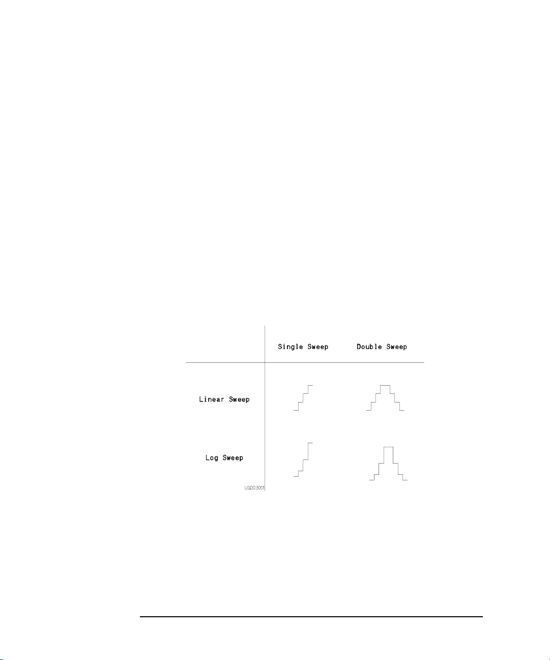
The following sweep types are available:
• LIN/LOG
• Linear staircase
• Logarithmic staircase
• SWEEP MODE
• Single Source channel sweeps the output from user specified start value to
stop value.
• Double Source channel sweeps the output from user specified start value to
stop value, then from stop value to start value.
You can select any combination of LIN/LOG and SWEEP MODE as shown in the
following table:
2-4 Agilent 4155B/4156B User’s Guide Vol.2, Edition 5
Page 45

Figure 2-1 Basic Sweep Measurement
Measurement Mode
Sweep Measurement Mode
To set up basic sweep measurement, select VAR1 function for desired SMU or VSU
on CHANNELS: CHANNEL DEFINITION page.
Parameters
Also, specify the following parameters for VAR1 on MEASURE: SWEEP SETUP
page.
Parameter Description
sweep mode Single or double sweep.
linear/log Linear or logarithmic sweep. For logarithmic sweep, select the
number steps in one decade as follows:
LOG10 10 steps in one decade.
LOG25 25 steps in one decade.
LOG50 50 steps in one decade.
Agilent 4155B/4156B User’s Guide Vol.2, Edition 5 2-5
Page 46

Measurement Mode
Sweep Measurement Mode
start Start value of sweep. For logarithmic sweep, start must not be
zero. Allowable range of start depends on output range of
sweep source. For output range of each measurement channel,
refer to Chapter 1.
stop Stop value of single sweep or turning back value of double
sweep. For logarithmic sweep, stop must have same polarity as
start, and must not be zero. Allowable range of stop depends on
output range of sweep source. For output range of each
measurement channel, refer to Chapter 1.
step • For linear sweep, step is step increment of sweep. Number
of sweep steps is calculated from start, stop, and step.
Calculated number of steps must be in range: 2 to 1001.
• For logarithmic sweep, step is invalid. Number of sweep
steps is calculated from start, stop, and number of steps in
one decade, which is specified by log parameter. Calculated
number of steps must be in range: 2 to 1001.
compliance Compliance value of sweep source. This parameter applies to
SMU only. Allowable range of compliance depends on the
compliance range of sweep source. For the compliance range of
each measurement channel, refer to Chapter 1.
power compliance (Optional) Power compliance value of sweep source. This
parameter applies to SMU only. Allowable range depends on
power compliance range of sweep source. For details, refer to
Chapter 3.
hold time Time required for DUT to settle after forcing start value.
Allowable range is 0 to 655.35s. Resolution: 10 ms.
delay time Time required for DUT to settle after stepping the output.
Allowable range: 0 to 65.535 s. Resolution: 100 ms
Refer to “CHANNELS: CHANNEL DEFINITION screen” and “MEASURE:
MEASURE SETUP screen” in Chapter 6 for setting up these parameters.
2-6 Agilent 4155B/4156B User’s Guide Vol.2, Edition 5
Page 47

Subordinate Sweep Measurement
For subordinate sweep measurement, you set up a secondary sweep source (VAR2)
in addition to a primary sweep source (VAR1). After primary sweep is completed,
the output of secondary sweep source is incremented or decremented by the
specified step value, then the primary sweep source is swept again.
Figure 2-2 Subordinate Sweep Measurement
Measurement Mode
Sweep Measurement Mode
To set up the subordinate sweep measurement, select the following on CHANNELS:
CHANNEL DEFINITION page:
• VAR1 function for desired primary sweep source (SMU or VSU).
• VAR2 function for desired secondary sweep source (SMU or VSU).
Subordinate sweep measurement has the following restriction:
• For the secondary sweep source, only single sweep mode and linear staircase
mode are available.
Agilent 4155B/4156B User’s Guide Vol.2, Edition 5 2-7
Page 48

Measurement Mode
Sweep Measurement Mode
Parameters
The parameters for primary sweep source (VAR1) are same as the parameters for
sweep source of basic sweep measurement. For secondary sweep source (VAR2),
specify the following parameters on MEASURE: SWEEP SETUP page.
Parameter Description
start Start value of secondary sweep. Allowable range of start
step Step increment of secondary sweep.
number of steps Number of secondary sweep steps.Allowable range: 1 to 128.
NOTE Stop value
Stop value of secondary sweep is calculated from start, step, and number of steps.
Allowable range of stop depends on the output range of secondary sweep source.
For the output range of each measurement channel, refer to Chapter 1.
compliance Compliance value of secondary sweep source. This parameter
depends on the output range of secondary sweep source. For the
output range of each measurement channel, refer to Chapter 1.
applies to SMU only. Allowable range of compliance depends
on the compliance range of secondary sweep source. For the
compliance range of each measurement channel, refer to
Chapter 1.
power compliance (Optional) Power compliance value of secondary sweep source.
This parameter applies to SMU only. Allowable range of power
compliance depends on the power compliance range of sweep
source. For details, refer to Chapter 3.
2-8 Agilent 4155B/4156B User’s Guide Vol.2, Edition 5
Page 49
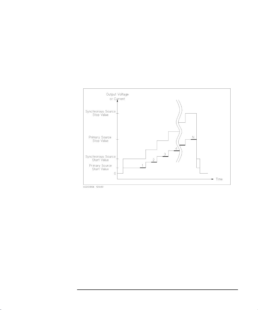
Synchronous Sweep Measurement
For synchronous sweep measurement, you set up a synchronous sweep source
(VAR1') in addition to a primary sweep source (VAR1). The output of the
synchronous sweep source is swept synchronously with the output of the primary
sweep source at a constant offset value and ratio.
Figure 2-3 Synchronous Sweep Measurement
Measurement Mode
Sweep Measurement Mode
To set up synchronous sweep measurement, select the following on CHANNELS:
CHANNEL DEFINITION page:
• VAR1 function for desired primary sweep source (SMU or VSU).
• VAR1' function for desired synchronous sweep source (SMU or VSU).
Synchronous sweep mode has the following restrictions:
• For the following, VAR1' is always set to the same mode as VAR1:
• linear/log staircase
• single/double sweep mode
• VAR1 and VAR1' must be same V/I output mode. For example, if VAR1 is set to
V mode, then VAR1' must be set to V or VPULSE mode.
Agilent 4155B/4156B User’s Guide Vol.2, Edition 5 2-9
Page 50

Measurement Mode
Sweep Measurement Mode
Parameters
The parameters for primary sweep source (VAR1) are same as the parameters for
sweep source of basic sweep measurement. For synchronous sweep source (VAR1'),
specify the following parameters on MEASURE: SWEEP SETUP page.
Parameter Description
offset Offset between outputs of primary and synchronous sweep
sources.
ratio Ratio between outputs of primary and synchronous sweep
sources.
compliance Compliance value of synchronous sweep source. This
parameter applies to SMU only. Allowable range of compliance
depends on the compliance range of synchronous sweep source.
For the compliance range of each measurement channel, refer to
Chapter 1.
power compliance (Optional) Power compliance value of synchronous sweep
source. This parameter applies to SMU only. Allowable range
of power compliance depends on the power compliance range
of synchronous sweep source. For details, refer to Chapter 3.
The relationship between the output of primary and synchronous sweep sources is
determined by the following equation:
synchronous output = primary output ´ ratio + offset
The synchronous output determined by above equation must not exceed the output
range of synchronous sweep source.
2-10 Agilent 4155B/4156B User’s Guide Vol.2, Edition 5
Page 51
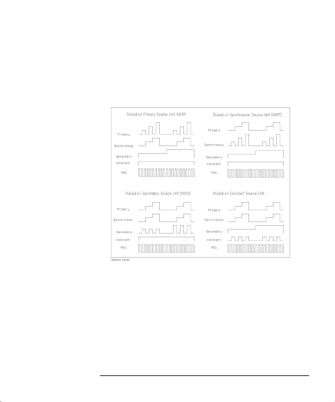
Pulse Sweep Measurement
For a sweep measurement, a sweep or constant source SMU can be a pulse source.
But only one SMU can be a pulse source. Figure 2-4 shows the relationship between
pulse source and other sources.
Figure 2-4 Pulse Source and Other Sources
Measurement Mode
Sweep Measurement Mode
For the pulse sweep measurement, the delay time of the primary sweep source is
ignored, and each step of the primary sweep source is synchronized with output of
the SMU pulse source. Measurements are made during the pulse output.
The pulse output of PGU is not synchronized with any other source.
Agilent 4155B/4156B User’s Guide Vol.2, Edition 5 2-11
Page 52

Measurement Mode
Sweep Measurement Mode
Figure 2-5 SMU Pulse
Parameters
Specify SMU pulse parameters (MEASURE: SWEEP SETUP):
Parameter Description
pulse period SMU forces the next pulse after specified pulse period.
Allowable range: 5 ms to 1 s. Resolution: 100 ms.
pulse width Time from when SMU output starts to change from base value
to time when SMU starts to return from peak value.
Measurements are made while the peak value is output.
Allowable range: 0.5 ms to 100 ms. Resolution: 100 ms.
base value The base output value of the SMU pulse.
Be aware that if any of following are true, pulsed SMU channel may not output the
pulse period and pulse width you specified:
• Measurement range differs from compliance range (lowest range that includes
compliance).
• Ranging mode is set to auto range or limited auto range.
• Multi-channel measurement is set.
2-12 Agilent 4155B/4156B User’s Guide Vol.2, Edition 5
Page 53

NOTE Pulse width
If the measurement settings do not meet the following conditions, pulse width
setting of SMU may be insufficient to make measurement. If so, the pulse width is
automatically changed to be appropriate.
Number of Meas. Channels: 1
Integration Time: Short
Ranging Mode: Fixed
Measurement Mode
Sweep Measurement Mode
Agilent 4155B/4156B User’s Guide Vol.2, Edition 5 2-13
Page 54

Measurement Mode
Sampling Measurement Mode
Sampling Measurement Mode
For a sampling measurement, you can monitor current or voltage changes at a DUT
while forcing constant current, constant voltage, or pulsed constant bias.
The 4155B/4156B provides the following three types of sampling measurement
according to the sampling interval:
•“Linear Sampling Measurement”
•“Thinned-out Sampling Measurement”
•“Logarithmic Sampling Measurement”
Available Units
Available units and functions for sampling measurement are shown below:
Output Function Output Mode
Unit
VAR1 VAR1' VAR2 CONST STANDBY V I COM V I
SMU n.a. n.a. n.a.
VSU n.a. n.a. n.a.
VMU
GNDU
PGU
---- - ----·-
---· - --· ---
---· · ·--·--
· · ···
·· ·-----
Pulse
n.a.
n.a. means "This is not available for sampling measurement".
· means "This is available for sampling measurement".
- means "This is not available for this unit".
For sampling measurements, only the PGU output can be pulsed.
The pulse output timing from PGU is not synchronized with the timing of sampling
measurement.
Meas.
Mode
··
2-14 Agilent 4155B/4156B User’s Guide Vol.2, Edition 5
Page 55

Measurement Mode
Sampling Measurement Mode
Sampling Interval and Measurement Time
When the sampling interval enough longer than the actual measurement time,
measurement unit repeats measurement every specified sampling interval. However,
if the sampling interval is less than the measurement time, measurement unit cannot
repeat measurements every specified interval. For example, if the measurement time
is one and a half the specified sampling interval, the interval of measurement is two
times the sampling interval. See Figure 2-6 which explains the operation of the
sampling measurement.
Measurement time depends on the measurement condition: integration time,
measurement range, and so on. So if you want to execute sampling measurement
with the specified sampling interval, you need to know the actual measurement time
upon your measurement setup, and set the sampling interval value enough longer
than the actual measurement time. You can see typical measurement time by
repeating the sampling measurements with several sampling interval settings. See
“Sampling Measurement Data” on page 2-18.
Measurement time is given by the following fomula:
Tmeas = Tinteg + Toh
where,
Tmeas : Measurement time.
Tinteg : Integration time.
Toh : Overhead time caused by the following elements:
• range changing time during measurement (when measurement
ranging mode is set to auto or limited auto)
• range changing time at measurement start (when using measurement
range less than the compliance value)
• time required for the compensation: getting compensation data and
compensating measurement data (when the automatic compensation
is set and executed)
Agilent 4155B/4156B User’s Guide Vol.2, Edition 5 2-15
Page 56

Measurement Mode
e
e
Sampling Measurement Mode
Figure 2-6 Sampling Measurement Operation Summary
Case 1. Sampling Interval > Meas. Ti me
SMU Output
PGU Output
Meas.
Time
Hold Time
2
4
Sampling
Interval
3
Trigger TriggerTrigger Trigger Trigger
6
Sampling
Interval
5
Sampling
Interval
Tim
1
Starts Sampling Stops Sampling
Case 2. Sampling Interval < Meas. Time
SMU Output
PGU Output
Meas. Time
Hold Time
2
1
Starts Sampling Stops Sampling
Sampling
Interval
3
Trigger Trigg erTrigger Trigger Trigger
Total Sampling Time (TOTAL SAMP. TIME)
(TOTAL SAMP. TIME is one of the stop co ndition.)
4
6
Sampling
Interval
5
Total Sampling Time (TOTAL SAMP. TIME)
(TOTAL SAMP. TIME is one of the stop conditi on.)
Sampling
Interval
7
Tim
7
2-16 Agilent 4155B/4156B User’s Guide Vol.2, Edition 5
Page 57

Measurement Mode
Sampling Measurement Mode
Sampling measurement is executed as explained below:
1. Forces constant current, constant voltage, or pulsed constant bias.
2. Waits hold time.
3. Triggers one point measurement.
4. Measurement unit executes measurement. Measurement result data is stored in
memory.
5. Triggers one point measurement. Interval of trigger is same as Sampling
Interval.
6. (Case 1) Measurement unit executes measurement if it is ready to measure.
Measurement result data is stored in memory.
(Case 2) Measurement unit waits next trigger if it is busy or in measurement.
7. Repeats steps 5 and 6 until that a sampling completion condition is satisfied.
In Figure 2-6, sampling measurement stops when the completion condition total
sampling time is satisfied.
Number of measurement data stored in memory depends on the sampling
completion condition. Maximum number is specified by the NO. OF SAMPLES
field of the MEASURE: SAMPLING SETUP screen. However the measurement
will be immediately stopped if a sampling completion condition is satisfied before
reaching the maximum number. For the sampling completion condition, see
“Sampling Completion” on page 2-20.
Agilent 4155B/4156B User’s Guide Vol.2, Edition 5 2-17
Page 58

Measurement Mode
Sampling Measurement Mode
Sampling Measurement Data
Measurement parameters of sampling measurement are set to the NAME column of
the DISPLAY: DISPLAY SETUP screen. Available parameters and example
parameters for the NAME field are listed in the table below:
Parameter
Name
@TIME Measurement start time. This is the time the measurement unit
starts one point measurement. This is different from timing of the
measurement trigger sent every sampling interval.
@INDEX Data index. Integer. This is the index numbered to measurement
data stored in memory.
V1 for example, SMU1 voltage output value or measured value.
I1 for example, SMU1 current output value or measured value.
Measurement start time can be expressed by the following fomula. This formula is
available for the measurement points before starting the discarding operation for the
linear sampling or thinned-out sampling. For logarithmic sampling, this is available
for the measurement points in the first decade.
@TIME = Thold + Tinterval ´ [(@INDEX - 1) + N]
where,
@TIME : Measurement start time.
Thold : Hold time.
Tinterval : Sampling interval.
Meanings of Parameter
@INDEX : Data index.
N : Number of triggers between two nearest measurement points. This
value is 0 if the sampling interval is enough longer than the
measurement time.
2-18 Agilent 4155B/4156B User’s Guide Vol.2, Edition 5
Page 59

Measurement Mode
Sampling Measurement Mode
For example, if Thold=10 ms, Tinterval=5 ms, and @TIME values are as shown
below, estimated measurement time is 15 ms to 20 ms, and there are 3 triggers
between @INDEX=1 and @INDEX=2.
• @TIME (for @INDEX=1) = 10 ms = 10 + 5 ´ [(1 - 1) + 0] ms
• @TIME (for @INDEX=2) = 30 ms = 10 + 5 ´ [(2 - 1) + 3] ms
Sampling Interval
Hold Time
TIME
Meas.time
@TIME(at @INDEX=1) @TIME(at @INDEX=2)
To Use Multiple Measurement Units
If you define multiple measurement parameters in the NAME column of the
DISPLAY: DISPLAY SETUP screen, sampling measurement is executed by using
multiple measurement units. Differences between this measurement and the
measurement using only one unit are shown below:
• Measurement Sequence
Measurement units start measurement in the order below:
Parameters for GRAPH: X ® Y1 ® Y2
Parameters for LIST: Order of No. assigned for the parameters
• Value of @TIME
@TIME stores the time the first measurement unit starts measurement.
@TIME does not store the time another unit starts measurement.
• Measurement Time
Measurement time is sum of the measurement time by all units. To execute
sampling measurement with the specified sampling interval, the sampling
interval must be enough longer than the measurement time.
Agilent 4155B/4156B User’s Guide Vol.2, Edition 5 2-19
Page 60

Measurement Mode
Sampling Measurement Mode
Sampling Completion
The sampling measurement completes when one of the following conditions is
satisfied:
• Stop condition
The stop condition is satisfied. See below.
• Total sampling time
The specified total sampling time has elapsed.
Available for linear and thinned-out sampling. Setting TOTAL SAMP.TIME to
auto or no limit disables this sampling completion condition.
• Number of sampling points
The specified number of samples has elapsed.
Available for logarithmic sampling. For linear sampling, setting
TOTAL SAMP.TIME to auto enables this sampling completion condition.
• Stop front-panel key
The Stop front-panel key is pressed.
• GPIB Command
The 4155B/4156B receives GPIB command to stop sampling.
• Emergency Condition
An emergency condition occurs on the 4155B/4156B.
• Interlock Open
Interlock terminal opens due to high voltage.
Stop Condition
The stop condition is defined by using the STOP CONDITION table of MEASURE:
SAMPLING SETUP screen. This function stops the measurement as shown below.
1. Compares the value of the parameter set to NAME field and the value defined in
THRESHOLD field.
2. Counts how many times the selected EVENT occurs.
3. When the count reaches the value defined in EVENT NO. field, sampling is
stopped immediately.
2-20 Agilent 4155B/4156B User’s Guide Vol.2, Edition 5
Page 61

Measurement Mode
Sampling Measurement Mode
To use this function, the INITIAL INTERVAL value must be set to 2 ms or more.
The INITIAL INTERVAL is the minimum resolution of the sampling interval. For
details about the INITIAL INTERVAL, see “Linear Sampling Measurement” on
page 2-24, “Thinned-out Sampling Measurement” on page 2-27, or “Logarithmic
Sampling Measurement” on page 2-30.
To set up the stop condition, specify the following parameters on the MEASURE:
SAMPLING SETUP screen.
Parameter Description
ENABLE/
DISABLE Enables or disables the stop condition.
ENABLE DELAY Delay time. in second. This is the time from starting sampling
measurement to enabling this function.
Allowable range: 0 to INITIAL INTERVAL ´ 32767 s.
Resolution: INITIAL INTERVAL.
NAME Name of measurement data or user function to monitor for stop
condition.
Val of EVENT.
THRESHOLD Threshold value at which to stop sampling measurement.
Th of EVENT.
EVENT Event for stop condition.
Val > Th True if NAME parameter value is greater than
THRESHOLD value.
Val < Th True if NAME parameter value is less than
THRESHOLD value.
|Val| > |Th| True if absolute NAME parameter value is
greater than absolute THRESHOLD value.
|Val| < |Th| True if absolute NAME parameter value is less
than absolute THRESHOLD value.
EVENT NO. Target value of the count the event occurs (true). When the
count of true is this value, sampling is immediately stopped.
Allowable range: 1 to 200.
Agilent 4155B/4156B User’s Guide Vol.2, Edition 5 2-21
Page 62

Measurement Mode
Sampling Measurement Mode
Source Output Sequence and Time Origin
Source unit output sequence and the time origin depends on the setup value of the
OUTPUT SEQUENCE MODE OF SAMPLING field in the MEASURE: OUTPUT
SEQUENCE screen. The following two modes are available for the field.
• SIMULTANEOUS mode
All source unit starts output at same timing. This timing is defined as the Time
Origin. See figure below.
2-22 Agilent 4155B/4156B User’s Guide Vol.2, Edition 5
Page 63

Measurement Mode
Sampling Measurement Mode
• SEQUENTIAL mode
Source units starts output in the order defined in the OUTPUT SEQUENCE
table of the MEASURE: OUTPUT SEQUENCE screen. Time Origin is when
the last source reaches the specified output value. See figure below.
If there is pulse bias sources (PGUs), they start to force pulse base value in the
order shown above, and start to force pulse bias at the Time Origin.
Agilent 4155B/4156B User’s Guide Vol.2, Edition 5 2-23
Page 64

Measurement Mode
Sampling Measurement Mode
Linear Sampling Measurement
Linear sampling mode keeps a constant sampling interval that is the interval of
measurement trigger. And if the measurement units are ready to measure, the units
start measurement, and the result data is stored in memory. This is repeated until one
of the sampling completion conditions is satisfied.
However, if both the following two conditions occur, linear sampling mode changes
the sampling interval to two times the previous sampling interval, and continues
sampling measurement.
• number of sampling points reaches specified NO.OF SAMPLES
• sampling completion condition is not satisfied
Example Operation
This example assumes the following sampling setup:
• INITIAL INTERVAL value is longer than the measurement time
• NO.OF SAMPLES value is set to 10
• TOTAL SAMP.TIME is long (for example, 50 ´ INITIAL INTERVAL). Do
not set to AUTO which enables the number of sampling points sampling
completion condition.
1. Executes one point measurement, and stores data in memory. Repeats this 10
times every sampling interval (INITIAL INTERVAL setting value) because of
the sampling interval enough longer than the measurement time.
2. If the sampling completion condition is not satisfied after 10 points
measurement, linear sampling mode changes the sampling interval to two times
the INITIAL INTERVAL, and continues sampling measurement.
To store new measurement data, linear sampling mode discards a data every
couple of nearest data as shown above. Data is updated every measurement.
2-24 Agilent 4155B/4156B User’s Guide Vol.2, Edition 5
Page 65

Measurement Mode
Sampling Measurement Mode
3. If the sampling completion condition is not satisfied after additional 5 points
measurement, linear sampling mode changes the sampling interval to two times
the previous interval, and continues sampling measurement. Measurement data
is updated as described in step 2.
4. This discarding and doubling of the sampling interval is repeated until the
sampling completion condition is satisfied. By the end of the measurement, 10
measurement result data is stored in memory.
Parameters
To set up the linear sampling measurement, specify the following parameters on
MEASURE: SAMPLING SETUP page. See Table 2-1.
Parameter Description
MODE Sampling mode. LINEAR.
INITIAL INTERVAL The sampling interval for first NO.OF SAMPLES samples.
Allowable range: 60 ms to 65.535 s.
NO.OF SAMPLES Number of data to be stored by end of measurement.
Maximum: 10001. If there are multiple measurement units,
this value must be 10001/(number of units) or less.
TOTAL SAMP.TIME Total sampling time. Does not include HOLD TIME. This is
the time from the 1st trigger to the sampling completion.
One of the sampling completion conditions, so sampling
stops after this time elapses.
• Allowable range when
INITIAL INTERVAL £ 480 ms:
AUTO
• Allowable range when
INITIAL INTERVAL ´ (NO.OF SAMPLES - 1) sec to
11
1 ´ 10
sec, AUTO, or NO LIMIT.
INITIAL INTERVAL > 480 ms:
AUTO Enables the number of sampling points sampling
completion condition.
NO LIMIT Disables the total sampling time sampling completion
condition
Agilent 4155B/4156B User’s Guide Vol.2, Edition 5 2-25
Page 66

Measurement Mode
Sampling Measurement Mode
HOLD TIME Hold time. This is the time from starting source output
to first trigger. If this value is 0, first @TIME value is 0.
• Allowable range when
INITIAL INTERVAL ³2 ms:
0 to 655.35 s with 100 ms resolution.
• Allowable range when
INITIAL INTERVAL <2 ms:
- 30 ms to 655.35 s with 100 ms resolution.
Table 2-1 Effective Parameter Values
INITIAL INTERVAL
NO.OF SAMPLES
TOTAL SAMP.TIME
HOLD TIME
60 ms to 480 ms560 ms to 1.92 ms 2 ms to 65.535 s
Max. 10001/(number of measurement units)
AUTO AUTO/NO LIMIT/
INITIAL INTERVAL ´ (NO.OF SAMPLES - 1) s
11
to 1 ´ 10
s
- 30 ms to 655.35 s, 100 ms resolution 0 to 655.35 s,
100 ms resolution
Stop Condition DISABLE DISABLE/ENABLE
a
Measurement Units
Measurement Range
Integration Time
e
b
1
d
FIX FIX/AUTO/LIMITED
Max. 8
Short Short/Medium/Long
c
a
Number of units (SMUs or VMUs) used for measurements.
b
If voltage source SMU is connected to R-BOX, only this SMU can be used for the
measurement.
c
Maximum 8 units if the 41501 is used (6 SMUs and 2 VMUs). If multiple
measurement units are used, total measurement time will be more than the sum of
the measurement time by all units.
d
If compliance value is more than the measurement range, range change when
starting measurement makes long measurement time. Also if ranging mode is set
to AUTO or LIMITED, range changing makes long measurement time.
e
Integration time is an element of the measurement time. If automatic measurement
data compensation is executed, the measurement time will be more than two times
the integration time.
2-26 Agilent 4155B/4156B User’s Guide Vol.2, Edition 5
Page 67

Measurement Mode
Sampling Measurement Mode
Thinned-out Sampling Measurement
Thinned-out sampling mode operates like the linear sampling mode. Difference is
that the sampling interval is not changed in the thinned-out sampling measurement.
So even if both the following two conditions occur, thinned-out sampling mode does
not change the sampling interval, and continues sampling measurement.
• number of sampling points reaches specified NO.OF SAMPLES
• sampling completion condition is not satisfied
Example Operation
This example assumes the following sampling setup:
• INITIAL INTERVAL value is longer than the measurement time
• NO.OF SAMPLES value is set to 10
1. Executes one point measurement, and stores data in memory. Repeats this 10
times every sampling interval (INITIAL INTERVAL setting value) because of
the sampling interval enough longer than the measurement time.
2. If the sampling completion condition is not satisfied after 10 points
measurement, thinned-out sampling mode keeps the sampling interval, and
continues sampling measurement.
To store new measurement data, thinned-out sampling mode discards a data
every couple of nearest data as shown above. Data is updated every
measurement.
Agilent 4155B/4156B User’s Guide Vol.2, Edition 5 2-27
Page 68

Measurement Mode
Sampling Measurement Mode
3. If the sampling completion condition is not satisfied after additional 5 points
measurement, thinned-out sampling mode keeps the sampling interval, and
continues sampling measurement. Data is updated as described in step 2.
4. This discarding is repeated until the sampling completion condition is satisfied.
By the end of the measurement, 10 measurement result data is stored in memory.
Parameters
To set up the thinned-out sampling measurement, specify the following parameters
on MEASURE: SAMPLING SETUP page. See Table 2-2.
Parameter Description
MODE Sampling mode. THINNED OUT.
INITIAL INTERVAL The sampling interval during thinned-out sampling.
Allowable range: 720 ms to 65.535 s.
NO.OF SAMPLES Number of data to be stored by end of measurement.
Maximum: 10001. If there are multiple measurement units,
this value must be 10001/(number of units) or less.
TOTAL SAMP.TIME Total sampling time. Does not include HOLD TIME. This is
the time from the 1st trigger to the sampling completion.
One of the sampling completion conditions, so sampling
stops after this time elapses.
Allowablerange:NOLIMIT,or
INITIAL INTERVAL ´ (NO.OF SAMPLES - 1) sec to
11
1 ´ 10
sec
NO LIMIT Disables the total sampling time sampling completion
condition
HOLD TIME Hold time. This is the time from starting source output to
first trigger. If this value is 0, first @TIME value is 0.
• Allowable range when
INITIAL INTERVAL ³2 ms:
0 to 655.35 s with 100 ms resolution.
• Allowable range when
INITIAL INTERVAL <2 ms:
- 30 ms to 655.35 s with 100 ms resolution.
2-28 Agilent 4155B/4156B User’s Guide Vol.2, Edition 5
Page 69

Table 2-2 Effective Parameter Values
Measurement Mode
Sampling Measurement Mode
INITIAL INTERVAL
NO.OF SAMPLES
TOTAL SAMP.TIME
HOLD TIME
720 ms to 1.92 ms 2 ms to 65.535 s
Max. 10001/(number of measurement units)
NO LIMIT/
INITIAL INTERVAL ´ (NO.OF SAMPLES - 1) s
11
to 1 ´ 10
- 30 ms to 655.35 s,
100 ms resolution
s
0to655.35 s,
100 ms resolution
Stop Condition DISABLE DISABLE/ENABLE
Measurement Units
a
Measurement Range
Integration Time
a
Number of units (SMUs or VMUs) used for measurements.
b
If voltage source SMU is connected to R-BOX, only this SMU can be used for the
e
b
1
d
FIX FIX/AUTO/LIMITED
Max. 8
c
Short Short/Medium/Long
measurement.
c
Maximum 8 units if the 41501 is used (6 SMUs and 2 VMUs). If multiple
measurement units are used, total measurement time will be more than the sum of
the measurement time by all units.
d
If compliance value is more than the measurement range, range change when
starting measurement makes long measurement time. Also if ranging mode is set
to AUTO or LIMITED, range changing makes long measurement time.
e
Integration time is an element of the measurement time. If automatic measurement
data compensation is executed, the measurement time will be more than two times
the integration time.
Agilent 4155B/4156B User’s Guide Vol.2, Edition 5 2-29
Page 70

Measurement Mode
M
Sampling Measurement Mode
Logarithmic Sampling Measurement
Logarithmic sampling mode plots the measurement data on the X-axis (@TIME) set
to the logarithmic scale by doing the following operation. See Figure 2-7.
1. Forces constant current, constant voltage, or pulsed constant bias.
2. Waits hold time.
3. Triggers one point measurement.
4. Measurement unit executes measurement. Measurement result data is stored in
memory.
5. Triggers one point measurement. Interval of trigger is constant (setting value of
INITIAL INTERVAL).
6. Measurement unit executes measurement if it is ready to measure. Measurement
result data is stored in memory.
Measurement unit waits next trigger if it is busy or in measurement.
7. Repeats steps 5 and 6 until that a sampling completion condition is satisfied.
Logarithmic sampling mode retains only the measurement data that can plot the
data on the logarithmic X-axis in almost the same interval.
Figure 2-7 Example Operation of Logarithmic Sampling
Starts
Sampling
Hold Time
3
2
1
4
easurement
Sampling Interval
5
Data of first decade
6
7
Discard
Second decadeFirst decade
Data of second decade
1/10 decade
TIME
This is the example
to plot LOG10 data.
@TIME
2-30 Agilent 4155B/4156B User’s Guide Vol.2, Edition 5
Page 71

Measurement Mode
Sampling Measurement Mode
@TIME Value
@TIME value of measurement data is determined by MODE, INITIAL
INTERVAL, NO. OF SAMPLES, and HOLD TIME parameters. Where MODE
decides number of measurement points in 1 decades. For example, LOG10 mode
obtains 10 data per 1 decade.
An example to get measurement data in logarithmic sampling measurement is
explained below. This example assumes the following settings. See also Figure 2-7.
• MODE = LOG10 (10 data / 1 decade)
• INITIAL INTERVAL = 10 ms
• NO.OF SAMPLES = 20
• HOLD TIME = 10 ms
• STOP CONDITION = DISABLE
If sampling interval is enough longer than measurement time:
INITIAL INTERVAL value decides the range of a decade.
10 ms to 100 ms (1st decade) Sampling is executed at the following @TIME
value: 10 ms, 20 ms, 30 ms, 40 ms, 50 ms, 60 ms, 70 ms, 80
ms, 90 ms, 100 ms. LOG10 mode allows to have 10 data in 1
decade. Therefore all measurement data is stored in memory.
100 ms to 1 s There are 90 sampling points in this range. Number of data can
remain is only 10. They can plot the data on the X-axis in
almost the same interval.
@TIME values are as follows:
140 ms, 170 ms, 210 ms, 270 ms, 330 ms, 410 ms, 520 ms,
650 ms, 810 ms, 1.02 s.
If sampling interval is less than measurement time:
Measurement time decides the range of a decade. If the measurement time is 18 ms,
interval of measurement is 20 ms, and the following data are stored in memory:
20 ms to 200 ms (1st decade) Sampling is executed at the following @TIME
value: 20 ms, 40 ms, 60 ms, 80 ms, 100 ms, 120 ms, 140 ms,
160 ms, 180 ms, 200 ms. LOG10 mode allows to have 10 data
in 1 decade. Therefore all data is stored in memory.
200 ms to 2 s There are 90 sampling points in this range. Number of data can
remain is only 10. They can plot the data on the X-axis in
almost the same interval.
Agilent 4155B/4156B User’s Guide Vol.2, Edition 5 2-31
Page 72

Measurement Mode
Sampling Measurement Mode
Rule to determine @TIME:
@TIME value is determined by the following rule. Data measured at @TIME=Tlog
are stored in memory.
Tlog ³ Ttarget
| Tlog - Ttarget | < | Ttarget - Tprev |
where,
Tlog Data stored in @TIME. Actual measurement point.
Ttarget Target value of @TIME. The values can plot data on the logarithmic
X-axis in the same interval completely.
Tprev Tlog - sampling interval. Actual measurement point.
Discard
Tprev Tlog
Sampling
Interval
Ttarget
BA
Measurement
Stored in @TIME
Ttarget < Tlog
A > B
TIME
A= | Ttarget - Tprev |
B=|Tlog - Ttarget |
2-32 Agilent 4155B/4156B User’s Guide Vol.2, Edition 5
Page 73

Measurement Mode
Sampling Measurement Mode
Parameters
To set up the logarithmic sampling measurement, specify the following parameters
on MEASURE: SAMPLING SETUP page. See Table 2-3.
Parameter Description
MODE Sampling mode. LOG10, LOG25, or LOG50.
MODE Number of data in 1 decade
LOG10 10
LOG25 25
LOG50 50
INITIAL INTERVAL The sampling interval during logarithmic sampling.
Allowable range: 560 ms to 65.535 s.
If this value is 560 ms to 10 ms, number of measurement
data may be less than the specified number of data for top 2
decades. Then sampling continues to get all samples.
NO.OF SAMPLES Number of data to be stored by end of measurement. One
of the sampling completion conditions, so sampling stops
after this point elapses. Maximum 11 decades.
MODE Maximum value
LOG10 111
LOG25 276
LOG50 551
HOLD TIME Hold time. This is the time from starting source output to
first trigger. If this value is 0, first @TIME value is 0.
• Allowable range when
INITIAL INTERVAL ³2 ms:
0 to 655.35 s with 100 ms resolution.
• Allowable range when
INITIAL INTERVAL <2 ms:
- 30 ms to 655.35 s with 100 ms resolution.
Example:
HOLD TIME=1.003 s, and measurement interval is 3 ms,
decade and its range are as shown below:
decade Range ( in sec )
1st decade 1.003 to 1.030 ( 3 m +1 to 30 m +1 )
2nd decade 1.030 to 1.300 ( 30 m +1 to 300 m +1 )
3rd decade 1.300 to 4.00 ( 300 m +1 to 3+1 )
4th decade 4 to 31 ( 3+1 to 30+1 )
5th decade 31 to 301 ( 30+1 to 300+1 )
Agilent 4155B/4156B User’s Guide Vol.2, Edition 5 2-33
Page 74

Measurement Mode
Sampling Measurement Mode
Table 2-3 Effective Parameter Values
INITIAL INTERVAL
NO.OF SAMPLES
HOLD TIME
560 ms to 1.92 ms 2 ms to 65.535 s
Maximum 111 (LOG10), 276 (LOG25), 551 (LOG50)
- 30 ms to 655.35 s,
100 ms resolution
0to655.35 s,
100 ms resolution
Stop Condition DISABLE DISABLE/ENABLE
a
b
Measurement Units
Measurement Range
Integration Time
a
Number of units (SMUs or VMUs) used for measurements.
b
If voltage source SMU is connected to R-BOX, only this SMU can be used for the
e
1
d
FIX FIX/AUTO/LIMITED
Short Short/Medium/Long
Max. 8
c
measurement.
c
Maximum 8 units if the 41501 is used (6 SMUs and 2 VMUs). If multiple
measurement units are used, total measurement time will be more than the sum of
the measurement time by all units.
d
If compliance value is more than the measurement range, range change when
starting measurement makes long measurement time. Also if ranging mode is set
to AUTO or LIMITED, range changing makes long measurement time.
e
Integration time is an element of the measurement time. If automatic measurement
data compensation is executed, the measurement time will be more than two times
the integration time.
2-34 Agilent 4155B/4156B User’s Guide Vol.2, Edition 5
Page 75

3 Measurement Functions
Agilent 4155B/4156B User’s Guide Vol.2, Edition 5
Page 76

Measurement Functions
This chapter explains functions that can be used in measurements. Agilent
4155B/4156B has the following useful measurement functions.
•“Stress Force Function”
•“Knob Sweep Function”
•“Operation States”
•“Standby Function”
•“Output Sequence”
•“Trigger Function”
•“SMU/PG Selector Control”
•“R-BOX Control”
•“Measurement Ranging Mode”
•“Compliance”
•“Integration Time”
•“SMU Filter”
•“Zero Offset Cancel”
3-2 Agilent 4155B/4156B User’s Guide Vol.2, Edition 5
Page 77

Measurement Functions
Stress Force Function
Stress Force Function
The 4155B/4156B can force both dc stress and ac stress (pulsed stress) as shown in
the following figure. Stress is defined as the bias that the 4155B/4156B can monitor
the bias output time correctly. To start stress force, press Stress front-panel key.
displaying the stress force time
The STRESS: STRESS FORCE screen is displayed while stress is being forced. On
this screen, the time that stress has been forced is displayed and updated every
second.
Agilent 4155B/4156B User’s Guide Vol.2, Edition 5 3-3
Page 78

Measurement Functions
Stress Force Function
Stress Output Channels
Stress output channel is defined as the unit used to force stress.
Available Units
The 4155B/4156B can force dc voltage stress, dc current stress, and ac voltage
stress (by PGUs in Agilent 41501A/B), but cannot force ac current stress.
Table 3-1 shows available units and allowable modes for stress sources.
Table 3-1 Available Units and Modes for Stress Force
Units DC Voltage Stress DC Current Stress
SMU yes yes
VSU yes
PGU yes yes
Also, SMUs can be set to COMMON mode.
AC Voltage Stress
(Pulsed Source)
Setting the Stress Channels
You can set up units for the stress force state on the STRESS: CHANNEL
DEFINITION screen independently from the measurement and standby states that
you set on the CHANNELS: CHANNEL DEFINITION screen.
For example, you can use the same SMU as a measurement channel in the
measurement state, and as a stress force source in the stress force state.
To set a unit to the stress channel, select SYNC in the FCTN field for the unit. If you
select NSYNC, the 4155B/4156B does not monitor the bias output time for the unit.
The unit is called as non-stress channel or bias channel in this manual.
To use the stress force function, at least one unit must be set to the stress channel
which the FCTN field is set to SYNC. You can select up to four stress source
channels among SMUs, VSUs, and PGUs.
If a unit is set to STBY ON on the CHANNELS: CHANNEL DEFINITION screen,
the unit cannot be set to the stress channel.
If you use two PGUs as ac pulse source, both PGUs must be the stress channel or the
non-stress channel. This means that if PGU1 is a stress channel, PGU2 must be a
stress channel, not non-stress channel.
3-4 Agilent 4155B/4156B User’s Guide Vol.2, Edition 5
Page 79

Measurement Functions
Stress Force Function
Switching Channels Connected to DUT
The 4155B/4156B can control Agilent 16440A SMU/Pulse Generator Selector to
automatically switch units that are connected to a DUT pin. You set up this
automatic control on the STRESS: CHANNEL DEFINITION screen.
For example, the DUT pin is connected to a PGU for stress force when Stress
front-panel key in the MEASUREMENT key group is pressed, then connected to an
SMU for measurement when Single front-panel key is pressed.
For details about how to control the 16440A selector, refer to “SMU/PG Selector
Control” on page 3-46.
External Stress Source
The following trigger functions allow you to force stress from more than 4 channels
by using external pulse generators, voltage sources, or current sources.
• gate trigger while stress is forced
The 4155B/4156B can output a gate trigger while stress channels are forcing
stress. For details about this gate trigger, refer to “Trigger Function” on page
3-39.
• gate trigger of PGUs
The output trigger terminal of PGUs (41501A/B) can output a gate trigger to
external pulse generators. So, use this function if you need more than two ac
stress channels.
For example, you can use Agilent 8110A pulse generator to force ac stress by
using this trigger.
PGU outputs a gate trigger that is synchronized with pulse output. For details of
the trigger signal, refer to “Trigger Output” on page 3-42.
Agilent 4155B/4156B User’s Guide Vol.2, Edition 5 3-5
Page 80

Measurement Functions
Stress Force Function
Stress Mode
You set stress mode to the pulse count mode or duration mode.
Pulse count mode
You specify the pulse count (1 to 65535). The total stress time is determined by the
pulse count and pulse period.
The pulse count mode is used only when a PGU is used to force ac stress (that is,
PGU is set to MODE=VPULSE and FCTN=SYNC on the STRESS:CHANNEL
DEFINITION screen).
Duration mode
You specify the total stress time directly in seconds. Allowable range is 500 ms to
1 year (3.1536´10
setting resolution:
• When the specified time is 10 s or less: 100 ms
• When the specified time is more than 10 s: 10 ms
7
s).
3-6 Agilent 4155B/4156B User’s Guide Vol.2, Edition 5
Page 81

Measurement Functions
Stress Force Function
Stress Force Sequence
This section explains the source output sequence when starting the stress force, and
when finishing the stress force.
• Output sequence from idle state to the stress state
• Output sequence in the stress state
• Output sequence from stress state to the idle state
Output sequence (idle state to the stress force state)
When the state changes from the idle state to the stress force state, the channels
output the following values:
ac stress (SYNC) channel: specified base value
dc stress (SYNC) channel: 0 V or 0 A
non-stress (NSYNC) channel: specified source value or pulse output
The output sequence of the channels depends on the order specified on the
MEASURE: OUTPUT SEQUENCE screen. For details, refer to “Sequential Mode”
on page 3-35.
Stress force sequence (in the stress force state)
• stress output
Stress force channels output stress at the same time when the stress start trigger
is received. Stress start trigger is sent hold time after the last channel changes
from idle state to stress force state.
• stress stop
Stress force channels stop stress at the same time. When you set up both ac and
dc stress on the STRESS: CHANNEL DEFINITION screen, ac stress channels
stop several microseconds before the dc stress channels.
If you set delay time for pulse stress, finish of stress force time is after the period
of the last pulse. (See Figure 3-1 on page 3-9.)
Agilent 4155B/4156B User’s Guide Vol.2, Edition 5 3-7
Page 82

Measurement Functions
Stress Force Function
NOTE Pulse Waveform when Stress Stops
When you set the duration mode or press the Stop front-panel key, be aware that
stress force may stop during the pulse peak output as shown in the following figure:
Sequence for returning to 0 V (stress force state to the idle state)
When the state changes from the stress state to the idle state, the outputs of the
channels are returned to 0 V in opposite order that forcing occurred.
Delay time of PGUs
When PGUs are set to VPULSE (ac source), you can set a delay time as follows:
• If PGU is set to SYNC, the PGU waits the delay time (after the stress start trigger
is received), then starts to force ac stress.
• If PGU is set to NSYNC, the PGU waits the delay time (after stress force state
starts), then starts pulse output.
Example
Figure 3-1 shows an example of output sequence when forcing stress.
Figure 3-1 assumes the output sequence is set on the MEASURE: OUTPUT
SEQUENCE screen as follows.
1. PGU1
2. SMU1
3. PGU2
4. SMU2
5. SMU3
3-8 Agilent 4155B/4156B User’s Guide Vol.2, Edition 5
Page 83

Figure 3-1 Example of the Stress Force Sequence
Measurement Functions
Stress Force Function
• output sequence from idle state to the stress state:
1. PGU1
2. SMU1
3. PGU2
4. SMU2
5. SMU3
• stress force sequence (in the stress force state):
The stress force channels (PGU1, PGU2, and SMU3) start stress and stop stress
at the same time.
• output sequence from stress state to the idle state:
1. SMU3
2. SMU2
3. PGU2
4. SMU1
5. PGU1
Agilent 4155B/4156B User’s Guide Vol.2, Edition 5 3-9
Page 84

Measurement Functions
Stress Force Function
Stress Stop Function at Abnormal Status
On the STRESS: STRESS SETUP screen, you can select whether the stress stops or
continues when an abnormal status occurs. When an 4155B/4156B is stopped by the
stress stop function, a message is displayed in the message display area.
The stress stop function is not effective until the stress has been forced for 10
seconds. For example, if STOP AT ANY ABNORM or STOP AT COMPLIANCE is
selected and abnormal status occurs after forcing stress for 5 seconds, the stop
function does not stop stress until stress is forced for 10 seconds.
Setting the Stress Stop Function
You can select one of the following in the STRESS Status field on the STRESS:
STRESS SETUP screen:
• STRESS Status = CONT AT ANY
Stress continues even if an abnormal status occurs.
• STRESS Status = STOP AT ANY ABNORM
Stress stops if any abnormal status occurs.
• STRESS Status = STOP AT COMPLIANCE
Stress stops only if SMU reaches its compliance setting.
STOP AT ANY ABNORM and STOP AT COMPLIANCE are available at the
following conditions:
• in PULSE COUNT mode: when pulse period ´ pulse count is more than 10 s.
• in DURATION mode: when specified duration is more than 10 s.
Abnormal Status
Abnormal statuses are as follows:
• SMU reaches its compliance setting.
• Current of a VSU exceeds ±100 mA.
• SMU or a VSU oscillates.
• A/D converter overflow occurs.
• Average current of PGU exceeds ±100 mA.
3-10 Agilent 4155B/4156B User’s Guide Vol.2, Edition 5
Page 85

Measurement Functions
Knob Sweep Function
Knob Sweep Function
The knob sweep function allows you to easily perform real-time sweep
measurements by rotating the rotary knob on the front panel. This function is useful
when you want to quickly make a rough measurement of a DUT characteristic, or
when you want to easily define a measurement setup for normal sweep.
To start the knob sweep measurement, press the green key and then the Single
front-panel key. The 4155B/4156B starts knob sweep measurement, and repeats
measurements continuously until this function is stopped. You can change the
measurement setups even while the measurements are being performed.
When knob sweep measurements are started, the VAR1 start value and VAR1 sweep
range are 0 V or 0 A. You change the sweep range from 0 to the stop value by
rotating the knob.
To stop the knob sweep measurements, press Stop front-panel key, or a PAGE
CONTROL group key. To restart the measurement, press the following key(s):
If you pressed the Stop key: Single key
If you pressed a PAGE CONTROL key: green key and Single key
Available units and functions
Table 3-2 shows available units and functions for knob sweep measurement.
Table 3-2 Available Units and Functions for Knob Sweep Measurement
Unit
VAR1 VAR1' VAR2
Output Function Output Mode
CONST
STAND
BY
VI
COMM
ON
Pulse
SMU · n.a. ······ n.a. ·- ·
VSU · n.a. ····----- -
VMU -------- -·· GNDU ---·---· --- -
PGU ---·· ·--·-- -
· means "This is available for knob sweep measurement".
n.a. means "This is not available for knob sweep measurement".
- means "This is not available for this unit".
Agilent 4155B/4156B User’s Guide Vol.2, Edition 5 3-11
Meas. Mode
V DVOLT I
Page 86

Measurement Functions
Knob Sweep Function
Normal Sweep and Knob Sweep Measurements
Table 3-3 compares the normal sweep measurement performed by measurement
front-panel keys and knob sweep measurement by the front-panel knob.
Table 3-3 Comparison of Sweep Measurement and Knob Sweep Measurement
Item Sweep Measurement Knob Sweep Measurement
Spacing of VAR1 linear or log linear
Sweep Mode of VAR1 single or double single or double
Number of Steps for VAR1 1 to 1001 1 to 1001
Hold Time 0 to 655.35 s 0 to 655.35 s
Power Compliance available not available
Measurement Ranging Mode auto, limited auto, or fixed
compliance range
Standby Function available available
Measurement Channel 1 to 8 ch 1 ch only
Output Sequence can set
can set
b
Trigger Function available not available
Integration Time short, medium, or long 80 ms
a
Measurement range is automatically set according to specified compliance value.
b
Settings on the MEASURE: OUTPUT SEQUENCE screen also apply to knob
sweep measurement.
a
3-12 Agilent 4155B/4156B User’s Guide Vol.2, Edition 5
Page 87

Measurement Functions
Knob Sweep Function
Features of Knob Sweep Function
The following are parameters that are for knob sweep measurement only or that
have a different meaning or range from normal sweep measurement.
LIN/LOG mode
Only linear mode is available. Even if you set LOG on the MEASURE: SWEEP
SETUP screen, the knob sweep is a linear sweep measurement.
VAR1 Range
To set the VAR1 range, refer to VAR1 RANGE softkey description in “VA R 1
SETUP Softkey” on page 3-20. If you do not set the VAR1 RANGE, the default is
the stop value specified for the VAR1 channel on the MEASURE: SWEEP SETUP
screen.
Polarity
The following sweep polarities are available for the knob sweep function of the
VAR1 source. To set the polarity, select VAR1 SETUP and POLARITY softkeys.
+ (positive) Used to set the sweep output in the positive X direction.
- (negative) Used to set the sweep output in the negative X direction.
+/- (bipolar) Used to set the sweep output in both the positive and negative X
directions.
To increase the source absolute value, rotate the rotary knob in clockwise.
To decrease the source value toward 0, rotate the rotary knob in counterclockwise.
When measurement curves reach 0, the curves remain at 0 even if you continue to
rotate the rotary knob counterclockwise.
Agilent 4155B/4156B User’s Guide Vol.2, Edition 5 3-13
Page 88

Measurement Functions
Knob Sweep Function
Step Time
Step time is the time width of a sweep step as shown in the following figure. For
knob sweep measurements, you cannot set the delay time. Instead, you set the step
time, which you can only set on the KNOB SWEEP screen.
Setup range is 0.5 ms to 100 ms, with 100 ms resolution.
For normal sweep measurement, the step time depends on the measurement time.
For knob sweep measurement, step time is always this specified value.
Measurement Channel
You select the measurement channel by selecting the Y-AXIS ASSIGN softkey on
the KNOB SWEEP screen, then selecting the desired secondary softkey. You can
select one measurement channel only, so the Y2 axis is not available on the KNOB
SWEEP screen.
• default measurement channel
• When an SMU is set to VAR1
Measurement channel is the VAR1 channel.
• When a VSU is set to VAR1
Measurement channel is the first found channel that can measure. Searching
order is:
SMU1 ® .....® SMU6 ® VMU1 ® VMU2.
• restrictions
If you use series resistance for VAR1 channel and VAR1 channel is V force
mode, only VAR1 measurement channel can be assigned to Y axis.
NOTE Measurement Resolution
When performing knob sweep measurement, measurement resolution of each
measurement unit is worse than the measurement resolution of normal sweep
measurements. For details of measurement resolution, refer to Chapter 1.
3-14 Agilent 4155B/4156B User’s Guide Vol.2, Edition 5
Page 89

Measurement Functions
Knob Sweep Function
Sweep Step Value
For the VAR1 channel, you do not set the step value. You can consider the step value
to be the amount you rotate the knob. Then, the sweep is performed for the specified
number of steps. The STEP field on the MEASURE: SWEEP SETUP screen has no
meaning.
Initial value: 0, Step value automatically set: 0 to VAR1 range/number of steps.
Number of Steps
For the VAR1 channel, you set the number of steps on the KNOB SWEEP screen.
So, for the knob sweep function, the number of steps for VAR1 has no relation to the
NO OF STEP setting on the MEASURE: SWEEP SETUP screen.
Start Value
The start value is always 0, and does not depend on the polarity. You cannot set the
start value. So, the START setting on the MEASURE: SWEEP SETUP screen has
no meaning for the knob sweep function.
Stop Value
Stop value is always step value ´ number of steps. You cannot set the stop value.
The measurement is continuously repeated from 0 to the stop value until the Stop
front-panel key is pressed or the KNOB SWEEP screen is changed to another
screen.
Measurement Range
If SMU is the measurement channel:
Compliance range is used. That is, the measurement range is set to the lowest range
that includes the compliance value that is set on the MEASURE: SWEEP SETUP
screen. For details about compliance range, refer to “Compliance Range” on page
3-56.
If VMU is the measurement channel:
20 V range is used for the grounded measurement mode, and the 2 V range is used
for the differential measurement mode.
Agilent 4155B/4156B User’s Guide Vol.2, Edition 5 3-15
Page 90

Measurement Functions
Knob Sweep Function
KNOB SWEEP screen
To start the knob sweep measurement, press the green key and then the Single
front-panel key. The 4155B/4156B displays KNOB SWEEP screen, and starts
measurements. To stop the knob sweep measurement, press the Stop front-panel key
or a PAGE CONTROL group key.
Cursor
On the KNOB SWEEP screen, the long cursor is always displayed, and you cannot
turn it off. In the CURSOR field, coordinate values of the cursor are displayed in X,
Y order.
X axis setting
X axis always plots the VAR1 source value. Maximum value of X axis is the setting
value of the VAR1 RANGE secondary softkey of VAR1 SETUP softkey group.
Y axis setting
Y axis always plots the measurement data of the measurement channel. You can
select the measurement channel by using the secondary softkeys of the Y-AXIS
ASSIGN softkey group. Maximum value of Y axis scale is the compliance value of
the measurement channel.
3-16 Agilent 4155B/4156B User’s Guide Vol.2, Edition 5
Page 91

Measurement Functions
Knob Sweep Function
Y-AXIS ASSIGN Softkey
This softkey is used to change the measurement channel. Before selecting this
softkey, the knob sweep measurement must be stopped. So press the Stop
front-panel key to change the measurement channel. To restart measurement, press
the Single front-panel key.
If you connect R-box to the VAR1 channel, and set the VAR1 to V force mode, the
measurement channel is automatically decided to the VAR1 channel. In this setup,
this softkey is not be displayed.
Y-AXIS ASSIGN primary softkey displays secondary softkeys used to select the
measurement channel. The measurement variable names of measurement channels
are labeled on the softkeys. User function is not available for the knob sweep
function. So there is no user function variable in the softkey label.
When you select a secondary softkey, the maximum absolute value(s) of the Y axis
are changed to compliance value of the selected measurement channel.
SETUP COPY Softkey
This softkey is used to memorize measurement setups used in the knob sweep
measurement mode. This function allows you to copy and use the setups in the
normal-sweep measurement mode.
1. Select this softkey to memorize the measurement setups.
2. Quit the knob sweep measurement mode using a PAGE CONTROL group key.
Then the measurement setups are copied to the normal-sweep setup screens.
The information memorized and copied is as following:
• Axis variables, axis values, and GRID settings:
copied to the DISPLAY: DISPLAY SETUP screen.
• Settings of VAR1, VAR2, CONST:
copied to the MEASURE: SWEEP SETUP screen.
Knob sweep measurement setup cannot be directly stored into a file. This function
allows you to save the setup as a normal-sweep measurement setup file. But the
setup data cannot be retrieved to the knob sweep mode.
Agilent 4155B/4156B User’s Guide Vol.2, Edition 5 3-17
Page 92

Measurement Functions
Knob Sweep Function
DISPLAY SETUP Softkey
This softkey displays secondary softkeys for setting the display format of graphics.
X-AXIS
REGION
+ Selects polarity of X-axis region displayed on the screen. This softkey
displays present setting.
• setting
Pressing this softkey toggles polarity as follows:
+ ® - ® +/- ® +
• default
If polarity of VAR1 stop and start value on MEASURE: SWEEP
SETUP screen are same, default value is same as polarity of stop
and start value.
If polarity of VAR1 stop and start value on MEASURE: SWEEP
SETUP screen are different, default value is +/-.
Y-AXIS
REGION
+ Selects polarity of Y-axis region displayed on the screen. This softkey
displays present setting.
• setting
Pressing this softkey toggles the polarity in the following order:
+ ® - ® +/- ® +
• default
polarity of VAR1 compliance value on the MEASURE: SWEEP
SETUP screen
3-18 Agilent 4155B/4156B User’s Guide Vol.2, Edition 5
Page 93

Measurement Functions
Knob Sweep Function
X-AXIS
DISPLAY
NORMAL Selects direction of the X-axis. This softkey displays present setting.
• setting
Selecting this softkey toggles NORMAL or REVERSE.
When NORMAL is selected:
• Minimum axis value is at left end of X-axis.
• Maximum axis value is at right end of X-axis.
When REVERSE is selected:
• Minimum axis value is at right end of X-axis.
• Maximum axis value is at left end of X-axis.
• default : NORMAL
Y-AXIS
DISPLAY
NORMAL Selects direction of the Y-axis. This softkey displays present setting.
• setting
Selecting this softkey toggles NORMAL or REVERSE.
When NORMAL is selected:
• Minimum axis value is at bottom of Y-axis.
• Maximum axis value is at top of Y-axis.
When REVERSE is selected:
• Minimum axis value is at top of Y-axis.
• Maximum axis value is at bottom of Y-axis.
• default : NORMAL
GRID
ON Selects grit on or off. This softkey displays present setting.
• setting
Pressing this softkey toggles the grid on or off in the plotting area.
• default : ON
Agilent 4155B/4156B User’s Guide Vol.2, Edition 5 3-19
Page 94

Measurement Functions
Knob Sweep Function
VAR1 SETUP Softkey
This softkey displays secondary softkeys for setting the primary sweep source
(VAR1) parameters.
SWEEP
MODE
SINGLE Selects sweep mode. This softkey displays present setting.
• setting
Pressing this softkey toggles the sweep mode in the following
order:
SINGLE ® DOUBLE ® SINGLE
• default
setting of the SWEEP MODE field on the MEASURE: SWEEP
SETUP screen
POLARITY
POS Selects polarity of sweep source. Changing the setting resets the sweep
step to 0, so the sweep measurement curve goes back to 0 on the screen.
For details, see “Sweep Step Value” on page 3-15. This softkey
displays present setting.
• setting
Pressing this softkey toggles the polarity of VAR1 channel in the
following order:
POS ® NEG ® BIPOLAR ® POS
• default
If polarity of VAR1 stop and start value on MEASURE: SWEEP
SETUP screen are same, default value is same as polarity of stop
and start value.
If polarity of VAR1 stop and start value on MEASURE: SWEEP
SETUP screen are different, default value is BIPOLAR.
3-20 Agilent 4155B/4156B User’s Guide Vol.2, Edition 5
Page 95

Measurement Functions
Knob Sweep Function
VAR1
RANGE
2V Sets sweep range of VAR1 channel. This setting defines the maximum
sweep range and resolution of VAR1 channel. This softkey displays
present setting.
• setting
Select this softkey to display the VAR1 sweep range value in the
data entry area, then rotate the knob to change the value. Setting
value will be changed by 1-2-5 steps as shown below:
0.1 V ® 0.2 V ® 0.5 V ® ... ® 100 V ®
200 V ® 0.1 V
• setting range
The allowed sweep range (1-2-5) values depend on the output range
of the measurement unit. See Chapter 1.
• default
Minimum value that includes VAR1 start and stop value that is set
on the MEASURE: SWEEP SETUP screen. However the value
must be 1-2-5 steps. For example, if start value is 0 V and stop
value is 30 V on the MEASURE: SWEEP SETUP screen, default
VA R1 ra ng e i s 50 V.
NUM OF
STEPS
101 Sets number of steps for VAR1 channel. For knob sweep, NO OF STEP
setting on MEASURE: SWEEP SETUP screen has no meaning. This
softkey displays present setting.
• setting
Press this softkey to display the number of steps in the data entry
area, then you can change the setting value by using the rotary
knob, numeric keys, or arrow keys in the Edit key group.
• setting range : 2 to 1001
• default : 101
Agilent 4155B/4156B User’s Guide Vol.2, Edition 5 3-21
Page 96

Measurement Functions
Knob Sweep Function
COMPLIANCE
100.mA Sets compliance value for VAR1 channel. This softkey displays present
setting.
• setting
Press this softkey to display the compliance value in the data entry
area. Then, you can change the setting value by using the rotary
knob, numeric keys, or arrow keys in the Edit key group.
• setting range
Compliance range depends on measurement unit. See Chapter 1.
• default
VAR1 compliance value on the MEASURE: SWEEP SETUP
screen
HOLD
TIME
0.00s Sets hold time. This softkey displays present setting.
• setting
Press this softkey to display the hold time in the data entry area.
Then, you can change the setting value by using the rotary knob,
numeric keys, or arrow keys in the Edit key group.
• setting range : 0 to 655.35 s with 10 ms resolution
• default : hold time on the MEASURE: SWEEP SETUP screen
STEP
TIME
500us Sets step time which is the time width of each sweep step. This softkey
displays present setting.
• setting
Press this softkey to display the step time in the data entry area, then
you can change the setting value by using the rotary knob, numeric
keys, or arrow keys in the Edit key group.
• setting range : 500 ms to 100 ms with 100 ms resolution
• default : 500 ms
3-22 Agilent 4155B/4156B User’s Guide Vol.2, Edition 5
Page 97

Measurement Functions
Knob Sweep Function
VAR2 SETUP Softkey
This softkey displays secondary softkeys for setting the secondary sweep source
(VAR2) parameters.
If VAR2 is not set for any channel on the CHANNELS: CHANNEL DEFINITION
screen, this softkey is not displayed.
VAR2
START
20.0uA Sets VAR2 start value. This softkey displays present setting.
• setting
Press this softkey to display the VAR2 start value in the data entry
area. Then, you can change the setting value by using the rotary
knob, numeric keys, or arrow keys in the Edit key group.
• setting range
Depends on the measurement unit. See Chapter 1.
• default
VAR2 start value on MEASURE: SWEEP SETUP screen
VAR2
STEP
20.0uA Sets VAR2 step value. This softkey displays present setting.
• setting
Press this softkey to display the VAR2 step value in the data entry
area. Then, you can change the setting value by using the rotary
knob, numeric keys, or arrow keys in the Edit key group.
• setting range
Depends on the measurement unit. See Chapter 1.
• default
VAR2 step value on MEASURE: SWEEP SETUP screen
Agilent 4155B/4156B User’s Guide Vol.2, Edition 5 3-23
Page 98

Measurement Functions
Knob Sweep Function
VAR2
POINTS
5 Sets Number of steps for VAR2 channel. This softkey displays present
setting.
• setting
Press this softkey to display the VAR2 number of steps in the data
entry area. Then, you can change the setting value by using the
rotary knob, numeric keys, or arrow keys in the Edit key group.
• setting range : 1 to 128
• default
VAR2 number of steps on MEASURE: SWEEP SETUP screen
COMPLIANCE
2.00 V Sets compliance value for VAR2 channel. This softkey displays present
setting.
• setting
Press this softkey to display the VAR2 compliance value in the data
entry area. Then, you can change the setting value by using the
rotary knob, numeric keys, or arrow keys in the Edit key group.
• setting range
Setting range depends on the measurement unit. See Chapter 1.
• default
VAR2 compliance value on MEASURE: SWEEP SETUP screen
3-24 Agilent 4155B/4156B User’s Guide Vol.2, Edition 5
Page 99

Measurement Functions
Knob Sweep Function
CONST SETUP Softkey
This softkey displays the secondary softkeys for setting the constant voltage source
parameter or the constant current source parameters. Secondary softkeys for PGUs
set to V mode are also displayed.
If CONST is not set for any channel on the CHANNELS: CHANNEL
DEFINITION screen, this softkey is not displayed.
If more than six constant channels are defined, press the MORE softkey to display
softkeys for the other constant channels.
Secondary softkeys
The first line of each secondary softkey displays the variable name of the constant
source. The second line displays source output value. For SMUs, the third line
displays compliance value. For other units, the third line is blank.
• Example. If an SMU is set as follows, the following softkey appears:
Vce
5.00V
10.0mA
• Voltage source mode.
• Variable name (VNAME): "Vce".
• Output voltage value: 5.0 V.
• Compliance value: 10 mA.
• source output value
Pressing the secondary softkey displays the source output value in the data entry
area. You can change the value by using the rotary knob, numeric keys, or arrow
keys in the Edit key group.
• compliance value (only for SMU)
Pressing the secondary softkey twice displays the compliance value in the data
entry area. You can change the compliance value by using the rotary knob,
numeric keys, or arrow keys in the Edit key group.
• setting range
Each setting range depends on the measurement unit. See Chapter 1.
Agilent 4155B/4156B User’s Guide Vol.2, Edition 5 3-25
Page 100

Measurement Functions
Knob Sweep Function
Analysis of the Knob Sweep Measurement Results
On the KNOB SWEEP screen, you cannot use analysis functions and user functions.
But you can analyze the knob sweep measurement result by quitting knob sweep
mode as shown below:
1. Select the SETUP COPY primary softkey on the KNOB SWEEP screen.
2. Press the Graph/List front-panel key.
The knob sweep results are displayed on the GRAPH/LIST screen. Then you can
use analysis functions.
To Use User Function
If you want to use user functions in GRAPH/LIST screen group, do following
before entering to the knob sweep mode:
1. Define user functions on CHANNELS: USER FUNCTION DEFINITION
screen.
2. Enter user function names in DATA VARIABLES field of DISPLAY: DISPLAY
SETUP screen.
3. On GRAPH/LIST: GRAPHICS screen, select DISPLAY SETUP primary
softkey, then set DATA VAR softkey to ON.
After getting the measurement data on the knob sweep mode, and quitting the knob
sweep mode as described above, the results of user function will be displayed on the
GRAPH/LIST screen.
3-26 Agilent 4155B/4156B User’s Guide Vol.2, Edition 5
 Loading...