


GPIB Command Reference
Agilent 4155C Semiconductor Parameter Analyzer
Agilent 4156C Precision Semiconductor Parameter Analyzer
Agilent Part No. 04156-90050
Printed in Japan January 2001
Edition 1

Legal Notice
The information contained in this document is subject to change without notice.
Copyright © 2001 Agilent Technologies
This document contains information which is protected by copyright. All rights are
reserved. Reproduction, adaptation, or translation without prior written permission
is prohibited, except as allowed under the copyright laws.
• Product Warranty
Agilent Technologies warrant Agilent Technologies hardware, accessories and
supplies against defects in materials and workmanship for the period of one year
from the warranty start date specified below. If Agilent Technologies receive
notice of such defects during the warranty period, Agilent Technologies will, at
its option, either repair or replace products which prove to be defective.
Replacement products may be either new or like-new.
Warranty service of this product will be performed at Agilent Technologies.
Buyer shall prepay shipping charges to Agilent Technologies and Agilent
Technologies shall pay shipping charges to return the product to Buyer.
However, Buyer shall pay all shipping charges, duties, and taxes for products
returned to Agilent Technologies from another country.
Agilent Technologies do not warrant that the operation of Agilent Technologies
products will be uninterrupted or error free. If Agilent is unable, within a
reasonable time, to repair or replace any product to a condition as warranted,
customer will be entitled to a refund of the purchase price upon prompt return of
the product.
The Agilent Technologies products may contain remanufactured parts
equivalent to new in performance or may have been subject to incidental use.
The warranty period begins on the date of delivery or on the date of installation
if installed by Agilent Technologies. If customer schedules or delays Agilent
Technologies installation more than 30 days after delivery, warranty begins on
the 31st day from delivery.
Warranty does not apply to defects resulting from (a) improper or inadequate
maintenance or calibration, (b) software, interfacing, parts or supplies not
supplied by Agilent Technologies, (c) unauthorized modification or misuse, (d)
operation outside of the published environmental specifications for the product,
or (e) improper site preparation or maintenance.
2 Agilent 4155C/4156C GPIB Command Reference, Edition 1

To the extent allowed by local law, the above warranties are exclusive and no
other warranty or condition, whether written or oral, is expressed or implied and
Agilent Technologies specifically disclaim any implied warranties or conditions
of merchantability, satisfactory quality, and fitness for a particular purpose.
Agilent Technologies will be liable for damage to tangible property per incident
up to the greater of $300,000 or the actual amount paid for the product that is the
subject of the claim, and for damages for bodily injury or death, to the extent
that all such damages are determined by a court of competent jurisdiction to
have been directly caused by a defective Agilent Technologies product.
To the extent allowed by local law, the remedies in this warranty statement are
customer’s sole and exclusive remedies. Expect as indicated above, in no event
will Agilent Technologies or its suppliers be liable for loss of date or for direct,
special, incidental, consequential (including lost profit or date), or other damage,
whether based in contract, tort, or otherwise.
For consumer transactions in Australia and New Zealand: the warranty terms
contained in this statement, except to the extent lawfully permitted, do not
exclude, restrict or modify and are in addition to the mandatory statutory rights
applicable to the sale of this product to you.
• Assistance
Product maintenance agreements and other customer assistance agreements are
available for Agilent Technologies products.
For any assistance, contact your nearest Agilent Technologies Sales Office.
• Certification
Agilent Technologies Inc. certifies that this product met its published
specifications at the time of shipment from the factory. Agilent further certifies
that its calibration measurements are traceable to the National Institute of
Standards and Technology (NIST), to the extent allowed by the Institute’s
calibration facility, and to the calibration facilities of other International
Standards Organization members.
Agilent 4155C/4156C GPIB Command Reference, Edition 1 3

Printing History
Edition 1: January 2001
Microsoft, Windows, MS-DOS and Excel are registered trademarks of Microsoft Corporation.
NFS is a trademark of Sun Microsystems, Inc.
4 Agilent 4155C/4156C GPIB Command Reference, Edition 1

In This Manual
Agilent 4155C/4156C provides three command modes to control the 4155C/4156C
via GPIB interface. You can control the 4155C/4156C using one of the following
command modes.
• 4155/4156 SCPI command mode
SCPI means Standard Commands for Programmable Instruments. This mode is
the default mode of the 4155C/4156C, and allows you to control the 4155C/
4156C functions except for the timestamp, search, and the enhanced stop
condition the FLEX mode supports.
• 4155/4156 FLEX command mode
FLEX means Fast Language for EXecution. This mode allows you to control
measurement functions of the 4155C/4156C. Command execution is faster than
the SCPI command mode.
• 4145 syntax command mode
This mode allows you to execute the 4145A/B programs on the 4155C/4156C
directly with little or no modification. In this command mode, you cannot
control all functions of the 4155C/4156C.
To confirm the present control mode, see the language mode indicator on the screen,
or enter the CMD? command.
Language indicator The indicator is located between the fourth primary softkey and
the fifth primary softkey, and next to the screen lock indicator.
The meaning of the indicator is as follows:
S: SCPI command mode
F: FLEX command mode
4: 4145 syntax command mode
CMD? command This query command returns the present command mode. The
response is as follows:
0: SCPI command mode
1: FLEX command mode
2: 4145 syntax command mode
This command is effective for all command mode.
Agilent 4155C/4156C GPIB Command Reference, Edition 1 5

This manual describes about the 4155C/4156C FLEX command set and the 4145
syntax command set, and consists of the following chapters:
• 4155C/4156C FLEX Commands
Lists the 4155C/4156C FLEX commands, and provides description, command
syntax, example statements, and so on. Also provides the command input
format, data output format, status byte information and error messages.
• 4145B Syntax Commmand Set
Lists the 4145 Syntax commands, and provides description, command syntax,
example statements, and so on. Also provides the general conventions,
differences from the 4145A/B commands and status byte information.
For information about the 4155C/4156C SCPI command set, refer to SCPI
Command Reference.
See User's Guide Measurement and Analysis and User's Guide General Information
for information about the 4155C/4156C itself.
Refer to Programmer's Guide to make a program and use built-in Instrument
BASIC controller.
NOTE 4155C/4156C FLEX command set
The 4155C/4156C FLEX command set includes some commands which have the
same name as the GPIB command of Agilent 4142B DC Source/Monitor. This is
useful for you who create the 4155C/4156C measurement program by modifying
the program created to control the 4142B.
However the 4155C/4156C commands are not fully compatible with the 4142B
commands. So you need to do some modifications on the measurement program for
the 4142B.
6 Agilent 4155C/4156C GPIB Command Reference, Edition 1

Contents
1. 4155C/4156C FLEX Commands
Control Mode . . . . . . . . . . . . . . . . . . . . . . . . . . . . . . . . . . . . . . . . . . . . . . . . . . . . 1-3
US/US42 Command . . . . . . . . . . . . . . . . . . . . . . . . . . . . . . . . . . . . . . . . . . . . . 1-4
To Quit FLEX Command Mode . . . . . . . . . . . . . . . . . . . . . . . . . . . . . . . . . . . . 1-5
To Use 4142B Measurement Program . . . . . . . . . . . . . . . . . . . . . . . . . . . . . . . 1-6
Command Input Format . . . . . . . . . . . . . . . . . . . . . . . . . . . . . . . . . . . . . . . . . . . . 1-8
Header. . . . . . . . . . . . . . . . . . . . . . . . . . . . . . . . . . . . . . . . . . . . . . . . . . . . . . . . . 1-8
Numeric Data . . . . . . . . . . . . . . . . . . . . . . . . . . . . . . . . . . . . . . . . . . . . . . . . . . . 1-9
Terminator . . . . . . . . . . . . . . . . . . . . . . . . . . . . . . . . . . . . . . . . . . . . . . . . . . . . 1-10
Special Terminator . . . . . . . . . . . . . . . . . . . . . . . . . . . . . . . . . . . . . . . . . . . . . . 1-10
Data Output Format . . . . . . . . . . . . . . . . . . . . . . . . . . . . . . . . . . . . . . . . . . . . . . 1-11
Conventions . . . . . . . . . . . . . . . . . . . . . . . . . . . . . . . . . . . . . . . . . . . . . . . . . . . 1-11
Time Stamp Function . . . . . . . . . . . . . . . . . . . . . . . . . . . . . . . . . . . . . . . . . . . . 1-11
ASCII Format in US Mode . . . . . . . . . . . . . . . . . . . . . . . . . . . . . . . . . . . . . . . 1-12
Binary Format in US Mode . . . . . . . . . . . . . . . . . . . . . . . . . . . . . . . . . . . . . . . 1-19
ASCII Format in US42 Mode . . . . . . . . . . . . . . . . . . . . . . . . . . . . . . . . . . . . . 1-28
Binary Format in US42 Mode . . . . . . . . . . . . . . . . . . . . . . . . . . . . . . . . . . . . . 1-33
Status Byte . . . . . . . . . . . . . . . . . . . . . . . . . . . . . . . . . . . . . . . . . . . . . . . . . . . . . 1-39
Command Reference . . . . . . . . . . . . . . . . . . . . . . . . . . . . . . . . . . . . . . . . . . . . . . 1-41
AB . . . . . . . . . . . . . . . . . . . . . . . . . . . . . . . . . . . . . . . . . . . . . . . . . . . . . . . . . . 1-48
ACH . . . . . . . . . . . . . . . . . . . . . . . . . . . . . . . . . . . . . . . . . . . . . . . . . . . . . . . . . 1-50
AV . . . . . . . . . . . . . . . . . . . . . . . . . . . . . . . . . . . . . . . . . . . . . . . . . . . . . . . . . . 1-52
AZ . . . . . . . . . . . . . . . . . . . . . . . . . . . . . . . . . . . . . . . . . . . . . . . . . . . . . . . . . . 1-53
BC . . . . . . . . . . . . . . . . . . . . . . . . . . . . . . . . . . . . . . . . . . . . . . . . . . . . . . . . . . 1-54
BGI . . . . . . . . . . . . . . . . . . . . . . . . . . . . . . . . . . . . . . . . . . . . . . . . . . . . . . . . . . 1-55
BGV . . . . . . . . . . . . . . . . . . . . . . . . . . . . . . . . . . . . . . . . . . . . . . . . . . . . . . . . . 1-58
BSI . . . . . . . . . . . . . . . . . . . . . . . . . . . . . . . . . . . . . . . . . . . . . . . . . . . . . . . . . . 1-61
BSM . . . . . . . . . . . . . . . . . . . . . . . . . . . . . . . . . . . . . . . . . . . . . . . . . . . . . . . . . 1-64
BSSI . . . . . . . . . . . . . . . . . . . . . . . . . . . . . . . . . . . . . . . . . . . . . . . . . . . . . . . . . 1-66
BSSV . . . . . . . . . . . . . . . . . . . . . . . . . . . . . . . . . . . . . . . . . . . . . . . . . . . . . . . . 1-68
Agilent 4155C/4156C GPIB Command Reference, Edition 1 Contents-1

Contents
BST . . . . . . . . . . . . . . . . . . . . . . . . . . . . . . . . . . . . . . . . . . . . . . . . . . . . . . . . . 1-70
BSV . . . . . . . . . . . . . . . . . . . . . . . . . . . . . . . . . . . . . . . . . . . . . . . . . . . . . . . . . 1-71
BSVM . . . . . . . . . . . . . . . . . . . . . . . . . . . . . . . . . . . . . . . . . . . . . . . . . . . . . . . 1-74
CA . . . . . . . . . . . . . . . . . . . . . . . . . . . . . . . . . . . . . . . . . . . . . . . . . . . . . . . . . . 1-75
*CAL? . . . . . . . . . . . . . . . . . . . . . . . . . . . . . . . . . . . . . . . . . . . . . . . . . . . . . . . 1-76
CL . . . . . . . . . . . . . . . . . . . . . . . . . . . . . . . . . . . . . . . . . . . . . . . . . . . . . . . . . . 1-77
CLOSE . . . . . . . . . . . . . . . . . . . . . . . . . . . . . . . . . . . . . . . . . . . . . . . . . . . . . . 1-79
*CLS . . . . . . . . . . . . . . . . . . . . . . . . . . . . . . . . . . . . . . . . . . . . . . . . . . . . . . . . 1-80
CM . . . . . . . . . . . . . . . . . . . . . . . . . . . . . . . . . . . . . . . . . . . . . . . . . . . . . . . . . 1-81
CMD?. . . . . . . . . . . . . . . . . . . . . . . . . . . . . . . . . . . . . . . . . . . . . . . . . . . . . . . . 1-82
CMM . . . . . . . . . . . . . . . . . . . . . . . . . . . . . . . . . . . . . . . . . . . . . . . . . . . . . . . . 1-83
CN . . . . . . . . . . . . . . . . . . . . . . . . . . . . . . . . . . . . . . . . . . . . . . . . . . . . . . . . . . 1-84
DI . . . . . . . . . . . . . . . . . . . . . . . . . . . . . . . . . . . . . . . . . . . . . . . . . . . . . . . . . . 1-86
DO . . . . . . . . . . . . . . . . . . . . . . . . . . . . . . . . . . . . . . . . . . . . . . . . . . . . . . . . . . 1-89
DV . . . . . . . . . . . . . . . . . . . . . . . . . . . . . . . . . . . . . . . . . . . . . . . . . . . . . . . . . . 1-90
DZ . . . . . . . . . . . . . . . . . . . . . . . . . . . . . . . . . . . . . . . . . . . . . . . . . . . . . . . . . . 1-93
END . . . . . . . . . . . . . . . . . . . . . . . . . . . . . . . . . . . . . . . . . . . . . . . . . . . . . . . . 1-95
ERR? . . . . . . . . . . . . . . . . . . . . . . . . . . . . . . . . . . . . . . . . . . . . . . . . . . . . . . . . 1-96
ESC . . . . . . . . . . . . . . . . . . . . . . . . . . . . . . . . . . . . . . . . . . . . . . . . . . . . . . . . . 1-97
*ESE(?) . . . . . . . . . . . . . . . . . . . . . . . . . . . . . . . . . . . . . . . . . . . . . . . . . . . . . 1-100
*ESR? . . . . . . . . . . . . . . . . . . . . . . . . . . . . . . . . . . . . . . . . . . . . . . . . . . . . . . 1-102
FL . . . . . . . . . . . . . . . . . . . . . . . . . . . . . . . . . . . . . . . . . . . . . . . . . . . . . . . . . 1-103
FMT . . . . . . . . . . . . . . . . . . . . . . . . . . . . . . . . . . . . . . . . . . . . . . . . . . . . . . . 1-104
GOC . . . . . . . . . . . . . . . . . . . . . . . . . . . . . . . . . . . . . . . . . . . . . . . . . . . . . . . 1-106
*IDN? . . . . . . . . . . . . . . . . . . . . . . . . . . . . . . . . . . . . . . . . . . . . . . . . . . . . . . 1-108
IN . . . . . . . . . . . . . . . . . . . . . . . . . . . . . . . . . . . . . . . . . . . . . . . . . . . . . . . . . 1-109
LGI . . . . . . . . . . . . . . . . . . . . . . . . . . . . . . . . . . . . . . . . . . . . . . . . . . . . . . . . . 1-111
LGV . . . . . . . . . . . . . . . . . . . . . . . . . . . . . . . . . . . . . . . . . . . . . . . . . . . . . . . 1-113
LOP? . . . . . . . . . . . . . . . . . . . . . . . . . . . . . . . . . . . . . . . . . . . . . . . . . . . . . . . 1-115
*LRN? . . . . . . . . . . . . . . . . . . . . . . . . . . . . . . . . . . . . . . . . . . . . . . . . . . . . . . 1-118
LSI . . . . . . . . . . . . . . . . . . . . . . . . . . . . . . . . . . . . . . . . . . . . . . . . . . . . . . . . . 1-125
LSSI . . . . . . . . . . . . . . . . . . . . . . . . . . . . . . . . . . . . . . . . . . . . . . . . . . . . . . . 1-128
Contents-2 Agilent 4155C/4156C GPIB Command Reference, Edition 1

Contents
LSSV . . . . . . . . . . . . . . . . . . . . . . . . . . . . . . . . . . . . . . . . . . . . . . . . . . . . . . . 1-130
LST? . . . . . . . . . . . . . . . . . . . . . . . . . . . . . . . . . . . . . . . . . . . . . . . . . . . . . . . 1-132
LSTM . . . . . . . . . . . . . . . . . . . . . . . . . . . . . . . . . . . . . . . . . . . . . . . . . . . . . . . 1-134
LSV . . . . . . . . . . . . . . . . . . . . . . . . . . . . . . . . . . . . . . . . . . . . . . . . . . . . . . . . 1-135
LSVM . . . . . . . . . . . . . . . . . . . . . . . . . . . . . . . . . . . . . . . . . . . . . . . . . . . . . . . 1-138
MCC . . . . . . . . . . . . . . . . . . . . . . . . . . . . . . . . . . . . . . . . . . . . . . . . . . . . . . . 1-139
MI . . . . . . . . . . . . . . . . . . . . . . . . . . . . . . . . . . . . . . . . . . . . . . . . . . . . . . . . . 1-140
MM . . . . . . . . . . . . . . . . . . . . . . . . . . . . . . . . . . . . . . . . . . . . . . . . . . . . . . . . 1-143
MP . . . . . . . . . . . . . . . . . . . . . . . . . . . . . . . . . . . . . . . . . . . . . . . . . . . . . . . . . 1-146
MSC . . . . . . . . . . . . . . . . . . . . . . . . . . . . . . . . . . . . . . . . . . . . . . . . . . . . . . . . 1-149
MT . . . . . . . . . . . . . . . . . . . . . . . . . . . . . . . . . . . . . . . . . . . . . . . . . . . . . . . . . 1-151
MV . . . . . . . . . . . . . . . . . . . . . . . . . . . . . . . . . . . . . . . . . . . . . . . . . . . . . . . . . 1-152
NUB? . . . . . . . . . . . . . . . . . . . . . . . . . . . . . . . . . . . . . . . . . . . . . . . . . . . . . . . 1-155
*OPC(?) . . . . . . . . . . . . . . . . . . . . . . . . . . . . . . . . . . . . . . . . . . . . . . . . . . . . . 1-156
OPEN . . . . . . . . . . . . . . . . . . . . . . . . . . . . . . . . . . . . . . . . . . . . . . . . . . . . . . . 1-157
*OPT? . . . . . . . . . . . . . . . . . . . . . . . . . . . . . . . . . . . . . . . . . . . . . . . . . . . . . . 1-158
OS . . . . . . . . . . . . . . . . . . . . . . . . . . . . . . . . . . . . . . . . . . . . . . . . . . . . . . . . . 1-159
PA . . . . . . . . . . . . . . . . . . . . . . . . . . . . . . . . . . . . . . . . . . . . . . . . . . . . . . . . . 1-160
PI . . . . . . . . . . . . . . . . . . . . . . . . . . . . . . . . . . . . . . . . . . . . . . . . . . . . . . . . . . 1-161
POR . . . . . . . . . . . . . . . . . . . . . . . . . . . . . . . . . . . . . . . . . . . . . . . . . . . . . . . . 1-164
PRN . . . . . . . . . . . . . . . . . . . . . . . . . . . . . . . . . . . . . . . . . . . . . . . . . . . . . . . . 1-165
PT . . . . . . . . . . . . . . . . . . . . . . . . . . . . . . . . . . . . . . . . . . . . . . . . . . . . . . . . . . 1-166
PV . . . . . . . . . . . . . . . . . . . . . . . . . . . . . . . . . . . . . . . . . . . . . . . . . . . . . . . . . 1-168
PWI . . . . . . . . . . . . . . . . . . . . . . . . . . . . . . . . . . . . . . . . . . . . . . . . . . . . . . . . 1-171
PWV . . . . . . . . . . . . . . . . . . . . . . . . . . . . . . . . . . . . . . . . . . . . . . . . . . . . . . . 1-175
QSL. . . . . . . . . . . . . . . . . . . . . . . . . . . . . . . . . . . . . . . . . . . . . . . . . . . . . . . . . 1-179
QSM . . . . . . . . . . . . . . . . . . . . . . . . . . . . . . . . . . . . . . . . . . . . . . . . . . . . . . . . 1-180
QSR . . . . . . . . . . . . . . . . . . . . . . . . . . . . . . . . . . . . . . . . . . . . . . . . . . . . . . . . 1-182
QST. . . . . . . . . . . . . . . . . . . . . . . . . . . . . . . . . . . . . . . . . . . . . . . . . . . . . . . . . 1-183
QSV . . . . . . . . . . . . . . . . . . . . . . . . . . . . . . . . . . . . . . . . . . . . . . . . . . . . . . . . 1-185
QSZ/QSZ? . . . . . . . . . . . . . . . . . . . . . . . . . . . . . . . . . . . . . . . . . . . . . . . . . . . 1-191
RBC . . . . . . . . . . . . . . . . . . . . . . . . . . . . . . . . . . . . . . . . . . . . . . . . . . . . . . . . 1-192
Agilent 4155C/4156C GPIB Command Reference, Edition 1 Contents-3

Contents
RCV . . . . . . . . . . . . . . . . . . . . . . . . . . . . . . . . . . . . . . . . . . . . . . . . . . . . . . . 1-193
RD? . . . . . . . . . . . . . . . . . . . . . . . . . . . . . . . . . . . . . . . . . . . . . . . . . . . . . . . . 1-194
RI . . . . . . . . . . . . . . . . . . . . . . . . . . . . . . . . . . . . . . . . . . . . . . . . . . . . . . . . . . 1-195
RMD? . . . . . . . . . . . . . . . . . . . . . . . . . . . . . . . . . . . . . . . . . . . . . . . . . . . . . . 1-201
*RST . . . . . . . . . . . . . . . . . . . . . . . . . . . . . . . . . . . . . . . . . . . . . . . . . . . . . . . 1-202
RU . . . . . . . . . . . . . . . . . . . . . . . . . . . . . . . . . . . . . . . . . . . . . . . . . . . . . . . . . 1-203
RV . . . . . . . . . . . . . . . . . . . . . . . . . . . . . . . . . . . . . . . . . . . . . . . . . . . . . . . . . 1-204
RZ . . . . . . . . . . . . . . . . . . . . . . . . . . . . . . . . . . . . . . . . . . . . . . . . . . . . . . . . . 1-209
SCR . . . . . . . . . . . . . . . . . . . . . . . . . . . . . . . . . . . . . . . . . . . . . . . . . . . . . . . . 1-210
SDSK . . . . . . . . . . . . . . . . . . . . . . . . . . . . . . . . . . . . . . . . . . . . . . . . . . . . . . 1-211
SIT . . . . . . . . . . . . . . . . . . . . . . . . . . . . . . . . . . . . . . . . . . . . . . . . . . . . . . . . . 1-212
SLI . . . . . . . . . . . . . . . . . . . . . . . . . . . . . . . . . . . . . . . . . . . . . . . . . . . . . . . . . 1-213
SOC . . . . . . . . . . . . . . . . . . . . . . . . . . . . . . . . . . . . . . . . . . . . . . . . . . . . . . . . 1-214
SPG . . . . . . . . . . . . . . . . . . . . . . . . . . . . . . . . . . . . . . . . . . . . . . . . . . . . . . . . 1-215
SPL . . . . . . . . . . . . . . . . . . . . . . . . . . . . . . . . . . . . . . . . . . . . . . . . . . . . . . . . 1-218
SPP . . . . . . . . . . . . . . . . . . . . . . . . . . . . . . . . . . . . . . . . . . . . . . . . . . . . . . . . 1-219
SPR . . . . . . . . . . . . . . . . . . . . . . . . . . . . . . . . . . . . . . . . . . . . . . . . . . . . . . . . 1-220
*SRE . . . . . . . . . . . . . . . . . . . . . . . . . . . . . . . . . . . . . . . . . . . . . . . . . . . . . . . 1-221
*SRE? . . . . . . . . . . . . . . . . . . . . . . . . . . . . . . . . . . . . . . . . . . . . . . . . . . . . . . 1-222
SRP . . . . . . . . . . . . . . . . . . . . . . . . . . . . . . . . . . . . . . . . . . . . . . . . . . . . . . . . 1-223
SSP . . . . . . . . . . . . . . . . . . . . . . . . . . . . . . . . . . . . . . . . . . . . . . . . . . . . . . . . 1-224
ST . . . . . . . . . . . . . . . . . . . . . . . . . . . . . . . . . . . . . . . . . . . . . . . . . . . . . . . . . 1-225
*STB? . . . . . . . . . . . . . . . . . . . . . . . . . . . . . . . . . . . . . . . . . . . . . . . . . . . . . . 1-227
STC . . . . . . . . . . . . . . . . . . . . . . . . . . . . . . . . . . . . . . . . . . . . . . . . . . . . . . . . 1-228
STG . . . . . . . . . . . . . . . . . . . . . . . . . . . . . . . . . . . . . . . . . . . . . . . . . . . . . . . . 1-229
STI . . . . . . . . . . . . . . . . . . . . . . . . . . . . . . . . . . . . . . . . . . . . . . . . . . . . . . . . . 1-230
STM . . . . . . . . . . . . . . . . . . . . . . . . . . . . . . . . . . . . . . . . . . . . . . . . . . . . . . . 1-234
STP . . . . . . . . . . . . . . . . . . . . . . . . . . . . . . . . . . . . . . . . . . . . . . . . . . . . . . . . 1-235
STT . . . . . . . . . . . . . . . . . . . . . . . . . . . . . . . . . . . . . . . . . . . . . . . . . . . . . . . . 1-238
STV . . . . . . . . . . . . . . . . . . . . . . . . . . . . . . . . . . . . . . . . . . . . . . . . . . . . . . . . 1-240
:SYST:ERR? . . . . . . . . . . . . . . . . . . . . . . . . . . . . . . . . . . . . . . . . . . . . . . . . . 1-243
TDI. . . . . . . . . . . . . . . . . . . . . . . . . . . . . . . . . . . . . . . . . . . . . . . . . . . . . . . . . 1-244
Contents-4 Agilent 4155C/4156C GPIB Command Reference, Edition 1

Contents
TDV . . . . . . . . . . . . . . . . . . . . . . . . . . . . . . . . . . . . . . . . . . . . . . . . . . . . . . . . 1-248
TI/TI? . . . . . . . . . . . . . . . . . . . . . . . . . . . . . . . . . . . . . . . . . . . . . . . . . . . . . . . 1-251
TM . . . . . . . . . . . . . . . . . . . . . . . . . . . . . . . . . . . . . . . . . . . . . . . . . . . . . . . . . 1-253
TSC. . . . . . . . . . . . . . . . . . . . . . . . . . . . . . . . . . . . . . . . . . . . . . . . . . . . . . . . . 1-254
TSQ?. . . . . . . . . . . . . . . . . . . . . . . . . . . . . . . . . . . . . . . . . . . . . . . . . . . . . . . . 1-255
TSR. . . . . . . . . . . . . . . . . . . . . . . . . . . . . . . . . . . . . . . . . . . . . . . . . . . . . . . . . 1-256
*TST? . . . . . . . . . . . . . . . . . . . . . . . . . . . . . . . . . . . . . . . . . . . . . . . . . . . . . . 1-257
TTI/TTI? . . . . . . . . . . . . . . . . . . . . . . . . . . . . . . . . . . . . . . . . . . . . . . . . . . . . 1-259
TTV/TTV? . . . . . . . . . . . . . . . . . . . . . . . . . . . . . . . . . . . . . . . . . . . . . . . . . . . 1-262
TV/TV? . . . . . . . . . . . . . . . . . . . . . . . . . . . . . . . . . . . . . . . . . . . . . . . . . . . . . 1-265
UNT? . . . . . . . . . . . . . . . . . . . . . . . . . . . . . . . . . . . . . . . . . . . . . . . . . . . . . . . 1-267
VM . . . . . . . . . . . . . . . . . . . . . . . . . . . . . . . . . . . . . . . . . . . . . . . . . . . . . . . . . 1-268
VMD. . . . . . . . . . . . . . . . . . . . . . . . . . . . . . . . . . . . . . . . . . . . . . . . . . . . . . . . 1-269
*WAI . . . . . . . . . . . . . . . . . . . . . . . . . . . . . . . . . . . . . . . . . . . . . . . . . . . . . . . 1-270
WI . . . . . . . . . . . . . . . . . . . . . . . . . . . . . . . . . . . . . . . . . . . . . . . . . . . . . . . . . 1-271
WM . . . . . . . . . . . . . . . . . . . . . . . . . . . . . . . . . . . . . . . . . . . . . . . . . . . . . . . . 1-275
WNU? . . . . . . . . . . . . . . . . . . . . . . . . . . . . . . . . . . . . . . . . . . . . . . . . . . . . . . 1-277
WR . . . . . . . . . . . . . . . . . . . . . . . . . . . . . . . . . . . . . . . . . . . . . . . . . . . . . . . . . 1-278
WS . . . . . . . . . . . . . . . . . . . . . . . . . . . . . . . . . . . . . . . . . . . . . . . . . . . . . . . . . 1-279
WSI . . . . . . . . . . . . . . . . . . . . . . . . . . . . . . . . . . . . . . . . . . . . . . . . . . . . . . . . 1-280
WSV . . . . . . . . . . . . . . . . . . . . . . . . . . . . . . . . . . . . . . . . . . . . . . . . . . . . . . . 1-283
WT . . . . . . . . . . . . . . . . . . . . . . . . . . . . . . . . . . . . . . . . . . . . . . . . . . . . . . . . . 1-286
WV . . . . . . . . . . . . . . . . . . . . . . . . . . . . . . . . . . . . . . . . . . . . . . . . . . . . . . . . 1-287
XE . . . . . . . . . . . . . . . . . . . . . . . . . . . . . . . . . . . . . . . . . . . . . . . . . . . . . . . . . 1-291
Error Messages . . . . . . . . . . . . . . . . . . . . . . . . . . . . . . . . . . . . . . . . . . . . . . . . . 1-292
2. 4145B Syntax Command Set
General Conventions . . . . . . . . . . . . . . . . . . . . . . . . . . . . . . . . . . . . . . . . . . . . . . . 2-3
Command Modes . . . . . . . . . . . . . . . . . . . . . . . . . . . . . . . . . . . . . . . . . . . . . . . . 2-3
Changing the Command Mode. . . . . . . . . . . . . . . . . . . . . . . . . . . . . . . . . . . . . . 2-3
Command and Screens for System Mode . . . . . . . . . . . . . . . . . . . . . . . . . . . . . 2-3
Agilent 4155C/4156C GPIB Command Reference, Edition 1 Contents-5

Contents
Parameter Separator . . . . . . . . . . . . . . . . . . . . . . . . . . . . . . . . . . . . . . . . . . . . . . 2-4
String Parameter. . . . . . . . . . . . . . . . . . . . . . . . . . . . . . . . . . . . . . . . . . . . . . . . . 2-4
Real Parameter . . . . . . . . . . . . . . . . . . . . . . . . . . . . . . . . . . . . . . . . . . . . . . . . . . 2-4
Semicolons and <whitespace>. . . . . . . . . . . . . . . . . . . . . . . . . . . . . . . . . . . . . . 2-4
Invalid Input. . . . . . . . . . . . . . . . . . . . . . . . . . . . . . . . . . . . . . . . . . . . . . . . . . . . 2-4
4145B Syntax Mode Status Byte . . . . . . . . . . . . . . . . . . . . . . . . . . . . . . . . . . . . 2-5
Differences from 4145A/B Commands . . . . . . . . . . . . . . . . . . . . . . . . . . . . . . . . 2-6
Non-supported Commands . . . . . . . . . . . . . . . . . . . . . . . . . . . . . . . . . . . . . . . . 2-6
Differences on Commands . . . . . . . . . . . . . . . . . . . . . . . . . . . . . . . . . . . . . . . . . 2-7
Running 4145A/B Program Directly on 4155C/4156C . . . . . . . . . . . . . . . . . . . 2-11
Spot Measurement . . . . . . . . . . . . . . . . . . . . . . . . . . . . . . . . . . . . . . . . . . . . . . 2-11
Sweep Steps in Logarithmic Step Mode . . . . . . . . . . . . . . . . . . . . . . . . . . . . . 2-11
Terminator . . . . . . . . . . . . . . . . . . . . . . . . . . . . . . . . . . . . . . . . . . . . . . . . . . . . 2-12
System Mode Commands . . . . . . . . . . . . . . . . . . . . . . . . . . . . . . . . . . . . . . . . . . 2-14
AS . . . . . . . . . . . . . . . . . . . . . . . . . . . . . . . . . . . . . . . . . . . . . . . . . . . . . . . . . . 2-16
CH . . . . . . . . . . . . . . . . . . . . . . . . . . . . . . . . . . . . . . . . . . . . . . . . . . . . . . . . . . 2-17
DE . . . . . . . . . . . . . . . . . . . . . . . . . . . . . . . . . . . . . . . . . . . . . . . . . . . . . . . . . . 2-18
DM . . . . . . . . . . . . . . . . . . . . . . . . . . . . . . . . . . . . . . . . . . . . . . . . . . . . . . . . . 2-19
DO . . . . . . . . . . . . . . . . . . . . . . . . . . . . . . . . . . . . . . . . . . . . . . . . . . . . . . . . . . 2-20
DT . . . . . . . . . . . . . . . . . . . . . . . . . . . . . . . . . . . . . . . . . . . . . . . . . . . . . . . . . . 2-22
FS . . . . . . . . . . . . . . . . . . . . . . . . . . . . . . . . . . . . . . . . . . . . . . . . . . . . . . . . . . 2-23
GL . . . . . . . . . . . . . . . . . . . . . . . . . . . . . . . . . . . . . . . . . . . . . . . . . . . . . . . . . . 2-24
GT . . . . . . . . . . . . . . . . . . . . . . . . . . . . . . . . . . . . . . . . . . . . . . . . . . . . . . . . . . 2-25
HT . . . . . . . . . . . . . . . . . . . . . . . . . . . . . . . . . . . . . . . . . . . . . . . . . . . . . . . . . . 2-26
IC . . . . . . . . . . . . . . . . . . . . . . . . . . . . . . . . . . . . . . . . . . . . . . . . . . . . . . . . . . . 2-27
IN . . . . . . . . . . . . . . . . . . . . . . . . . . . . . . . . . . . . . . . . . . . . . . . . . . . . . . . . . . 2-28
IP . . . . . . . . . . . . . . . . . . . . . . . . . . . . . . . . . . . . . . . . . . . . . . . . . . . . . . . . . . . 2-29
IR . . . . . . . . . . . . . . . . . . . . . . . . . . . . . . . . . . . . . . . . . . . . . . . . . . . . . . . . . . . 2-30
LI . . . . . . . . . . . . . . . . . . . . . . . . . . . . . . . . . . . . . . . . . . . . . . . . . . . . . . . . . . . 2-31
MD . . . . . . . . . . . . . . . . . . . . . . . . . . . . . . . . . . . . . . . . . . . . . . . . . . . . . . . . . 2-32
Contents-6 Agilent 4155C/4156C GPIB Command Reference, Edition 1

Contents
ME . . . . . . . . . . . . . . . . . . . . . . . . . . . . . . . . . . . . . . . . . . . . . . . . . . . . . . . . . . 2-33
MX . . . . . . . . . . . . . . . . . . . . . . . . . . . . . . . . . . . . . . . . . . . . . . . . . . . . . . . . . . 2-34
NR . . . . . . . . . . . . . . . . . . . . . . . . . . . . . . . . . . . . . . . . . . . . . . . . . . . . . . . . . . 2-35
PR . . . . . . . . . . . . . . . . . . . . . . . . . . . . . . . . . . . . . . . . . . . . . . . . . . . . . . . . . . 2-36
RT . . . . . . . . . . . . . . . . . . . . . . . . . . . . . . . . . . . . . . . . . . . . . . . . . . . . . . . . . . 2-37
SC . . . . . . . . . . . . . . . . . . . . . . . . . . . . . . . . . . . . . . . . . . . . . . . . . . . . . . . . . . 2-38
SH . . . . . . . . . . . . . . . . . . . . . . . . . . . . . . . . . . . . . . . . . . . . . . . . . . . . . . . . . . 2-39
SM . . . . . . . . . . . . . . . . . . . . . . . . . . . . . . . . . . . . . . . . . . . . . . . . . . . . . . . . . . 2-40
SS . . . . . . . . . . . . . . . . . . . . . . . . . . . . . . . . . . . . . . . . . . . . . . . . . . . . . . . . . . . 2-41
SV . . . . . . . . . . . . . . . . . . . . . . . . . . . . . . . . . . . . . . . . . . . . . . . . . . . . . . . . . . 2-42
VC . . . . . . . . . . . . . . . . . . . . . . . . . . . . . . . . . . . . . . . . . . . . . . . . . . . . . . . . . . 2-43
VM . . . . . . . . . . . . . . . . . . . . . . . . . . . . . . . . . . . . . . . . . . . . . . . . . . . . . . . . . . 2-44
VP . . . . . . . . . . . . . . . . . . . . . . . . . . . . . . . . . . . . . . . . . . . . . . . . . . . . . . . . . . 2-45
VR . . . . . . . . . . . . . . . . . . . . . . . . . . . . . . . . . . . . . . . . . . . . . . . . . . . . . . . . . . 2-46
VS . . . . . . . . . . . . . . . . . . . . . . . . . . . . . . . . . . . . . . . . . . . . . . . . . . . . . . . . . . 2-47
WT . . . . . . . . . . . . . . . . . . . . . . . . . . . . . . . . . . . . . . . . . . . . . . . . . . . . . . . . . . 2-48
XN, YA, YB . . . . . . . . . . . . . . . . . . . . . . . . . . . . . . . . . . . . . . . . . . . . . . . . . . 2-49
XT . . . . . . . . . . . . . . . . . . . . . . . . . . . . . . . . . . . . . . . . . . . . . . . . . . . . . . . . . . 2-50
User Mode Commands . . . . . . . . . . . . . . . . . . . . . . . . . . . . . . . . . . . . . . . . . . . . 2-51
DI . . . . . . . . . . . . . . . . . . . . . . . . . . . . . . . . . . . . . . . . . . . . . . . . . . . . . . . . . . . 2-52
DS . . . . . . . . . . . . . . . . . . . . . . . . . . . . . . . . . . . . . . . . . . . . . . . . . . . . . . . . . . 2-53
DV . . . . . . . . . . . . . . . . . . . . . . . . . . . . . . . . . . . . . . . . . . . . . . . . . . . . . . . . . . 2-54
GL . . . . . . . . . . . . . . . . . . . . . . . . . . . . . . . . . . . . . . . . . . . . . . . . . . . . . . . . . . 2-55
TI . . . . . . . . . . . . . . . . . . . . . . . . . . . . . . . . . . . . . . . . . . . . . . . . . . . . . . . . . . . 2-56
TV . . . . . . . . . . . . . . . . . . . . . . . . . . . . . . . . . . . . . . . . . . . . . . . . . . . . . . . . . . 2-58
HP-GL Commands . . . . . . . . . . . . . . . . . . . . . . . . . . . . . . . . . . . . . . . . . . . . . 2-60
Common Mode Commands . . . . . . . . . . . . . . . . . . . . . . . . . . . . . . . . . . . . . . . . 2-61
BC . . . . . . . . . . . . . . . . . . . . . . . . . . . . . . . . . . . . . . . . . . . . . . . . . . . . . . . . . . 2-62
CA . . . . . . . . . . . . . . . . . . . . . . . . . . . . . . . . . . . . . . . . . . . . . . . . . . . . . . . . . . 2-63
CMD? . . . . . . . . . . . . . . . . . . . . . . . . . . . . . . . . . . . . . . . . . . . . . . . . . . . . . . . . 2-64
DC . . . . . . . . . . . . . . . . . . . . . . . . . . . . . . . . . . . . . . . . . . . . . . . . . . . . . . . . . . 2-65
Agilent 4155C/4156C GPIB Command Reference, Edition 1 Contents-7

Contents
DL . . . . . . . . . . . . . . . . . . . . . . . . . . . . . . . . . . . . . . . . . . . . . . . . . . . . . . . . . . 2-66
DP . . . . . . . . . . . . . . . . . . . . . . . . . . . . . . . . . . . . . . . . . . . . . . . . . . . . . . . . . . 2-67
DR . . . . . . . . . . . . . . . . . . . . . . . . . . . . . . . . . . . . . . . . . . . . . . . . . . . . . . . . . . 2-68
EI . . . . . . . . . . . . . . . . . . . . . . . . . . . . . . . . . . . . . . . . . . . . . . . . . . . . . . . . . . . 2-69
ID . . . . . . . . . . . . . . . . . . . . . . . . . . . . . . . . . . . . . . . . . . . . . . . . . . . . . . . . . . 2-70
IT . . . . . . . . . . . . . . . . . . . . . . . . . . . . . . . . . . . . . . . . . . . . . . . . . . . . . . . . . . . 2-71
PF . . . . . . . . . . . . . . . . . . . . . . . . . . . . . . . . . . . . . . . . . . . . . . . . . . . . . . . . . . 2-72
PL . . . . . . . . . . . . . . . . . . . . . . . . . . . . . . . . . . . . . . . . . . . . . . . . . . . . . . . . . . 2-73
SF . . . . . . . . . . . . . . . . . . . . . . . . . . . . . . . . . . . . . . . . . . . . . . . . . . . . . . . . . . 2-74
Contents-8 Agilent 4155C/4156C GPIB Command Reference, Edition 1

1 4155C/4156C FLEX Commands
Agilent 4155C/4156C GPIB Command Reference, Edition 1

4155C/4156C FLEX Commands
This chapter provides the following information:
•“Control Mode”
•“Command Input Format”
•“Data Output Format”
•“Status Byte”
•“Command Reference”
•“Error Messages”
1-2 Agilent 4155C/4156C GPIB Command Reference, Edition 1

4155C/4156C FLEX Commands
Control Mode
To use the 4155C/4156C FLEX commands, enter the US or US42 command when
the 4155C/4156C is in one of the following state. This command causes the
4155C/4156C control mode transition.
• Power on state
• Interactive operation mode (normal operation mode, which is not GPIB control
mode)
• 4155C/4156C SCPI command control mode
The control mode transition resets the 4155C/4156C settings. For the initial settings
in the FLEX command control mode, see the *RST command in the “Command
Reference” section in this chapter.
In the FLEX command control mode, you can use the all commands described in
this chapter, and the SCPI commands and the 4145A/B syntax commands are not
available.
If you use the built-in IBASIC controller, use the full IBASIC screen. All front panel
keys except for the following keys are available.
• MEASUREMENT key group
•
Plot/Print key
•
Save and Get keys
• IBASIC
Display key
If you use an external controller, the screen and front panel keys on the
4155C/4156C front panel are not available. Only the LOCAL secondary softkey is
available. This softkey is used to release the remote control state of the
4155C/4156C.
Agilent 4155C/4156C GPIB Command Reference, Edition 1 1- 3

4155C/4156C FLEX Commands
US/US42 Command
US/US42 Command
Syntax, command parameters, and example statements for the US and US42
command are shown below.
Difference between US command and US42 command is that the US42 command
provides the 4142B DC Source/Monitor-like response for the following items:
• Output data format
• Query response
• Status code (status byte)
Syntax Syntax of US command:
US
Syntax of US42 command:
US42[level]
Parameters level Support level for the 4142B-like response. Must be an integer. Refer to
the following table. If you do not specify this parameter, level is set to
255 (1+2+4+8+16+32+64+128). This means all levels are selected.
Example
Statements
If you select multiple levels, enter a value that is the sum of the desired
level values. For example, if you select levels 1, 2 and 4, enter 7
(1+2+4) as the level value.
OUTPUT @Hp4156;"US"
OUTPUT @Hp4156;"US42"
OUTPUT @Hp4156;"US42 15"
1-4 Agilent 4155C/4156C GPIB Command Reference, Edition 1

4155C/4156C FLEX Commands
To Quit FLEX Command Mode
level Description
1 Supports the 4142B-like data output format. (FMT command
allows you to select data output format.)
2 Supports the 4142B-like status code (status byte).
4 Supports the 4142B-like query response.
8 Supports the 4142B-like GNDU, VMU output switch setting.
(GNDU and VMU output switches are set to ON after executing
the CL command without specifying channel number.)
16
32 Not defined.
64 Not defined.
128 Not defined.
a. Without level=16, you need to enter the RMD? command before enter-
ing the command (ex; ENTER (HP BASIC) command) to read the output data. If you select level=16, you do not need the RMD? command.
But you cannot read the output data correctly if both output data and
query response are in the 4155C/4156C output buffer.
Reads output data without RMD? command.
a
To Quit FLEX Command Mode
To quit the FLEX command control mode, do one of the following:
• Enter the :PAGE command (ex: OUTPUT @Hp415x;":PAGE")
• Enter the LOCAL (HP BASIC) command
• If you use an external controller: Select the LOCAL secondary softkey
displayed on the 4155C/4156C screen.
• If you use the built-in IBASIC controller: Press any key in the PAGE
CONTROL key group.
The control mode transition resets the 4155C/4156C settings except for the auto
calibration mode setting. Auto calibration is set to OFF forcibly.
Agilent 4155C/4156C GPIB Command Reference, Edition 1 1- 5

4155C/4156C FLEX Commands
To Use 4142B Measurement Program
To Use 4142B Measurement Program
If you want to use the measurement program created to control Agilent 4142B
Modular DC Source/Monitor, remember the following precautions. You need to
modify the measurement program.
• Command syntax:
The 4155C/4156C FLEX commands need a space between the command and its
command parameter. The 4142B commands do not need a space.
Add a space between the command and the first command parameter as shown
in the following example:
• For 4142B:
OUTPUT @Hp4142;"DV1,0,20" !Applies 20V
• For 4155C/4156C:
OUTPUT @Hp4156;"DV 1,0,20" !Applies 20V
• Reading output data:
To read the 4155C/4156C output data after a measurement, use the RMD?
command as shown in the following example:
• For 4142B:
OUTPUT @Hp4142;"XE" !Executes measurements
ENTER @Hp4142;A$ !Reads measurement data
• For 4155C/4156C:
OUTPUT @Hp4156;"XE" !Executes measurements
OUTPUT @Hp4156;"RMD?" !Puts data on the output buffer
ENTER @Hp4156;A$ !Reads measurement data
If you select level=16 for the US42 command parameter, you do not need the
RMD? command before the ENTER command on this example. But you cannot
read the output data correctly if both output data and query response are in the
4155C/4156C output buffer.
1-6 Agilent 4155C/4156C GPIB Command Reference, Edition 1

4155C/4156C FLEX Commands
To Use 4142B Measurement Program
• Command parameters:
For the 4155C/4156C FLEX commands which have the same name as the
4142B commands, such as DV and DI, the meaning and order of most
parameters are the same as the 4142B commands. However, the values available
for the command parameter will be different from the 4142B control command
because of the difference in measurement performance. Also, some optional
command parameters may be added.
Confirm the command parameters and the available values.
• Measurement unit channel numbers:
The channel numbers of the measurement units must be changed. To change the
channel numbers, use the ACH command. The ACH command translates the
channel numbers for the 4142B to the channel numbers for the 4155C/4156C.
For details, see the ACH command in the “Command Reference” section in this
chapter.
• Unsupported commands:
The following 4142B commands are not supported by the 4155C/4156C.
AIV, ASM, ASV, AVI, BDM, BDT, BDV, ERC,
PDI, PDM, PDV, POL
• Multiple command strings
The 4155C/4156C FLEX command mode does not support the multiple
command strings such as the following example. Do not enter the multiple
command strings.
OUTPUT @Hp415x;"CN 1;DV 1,0,5;MM 1,1"
Agilent 4155C/4156C GPIB Command Reference, Edition 1 1- 7
4155C/4156C FLEX Commands
Header
Command Input Format
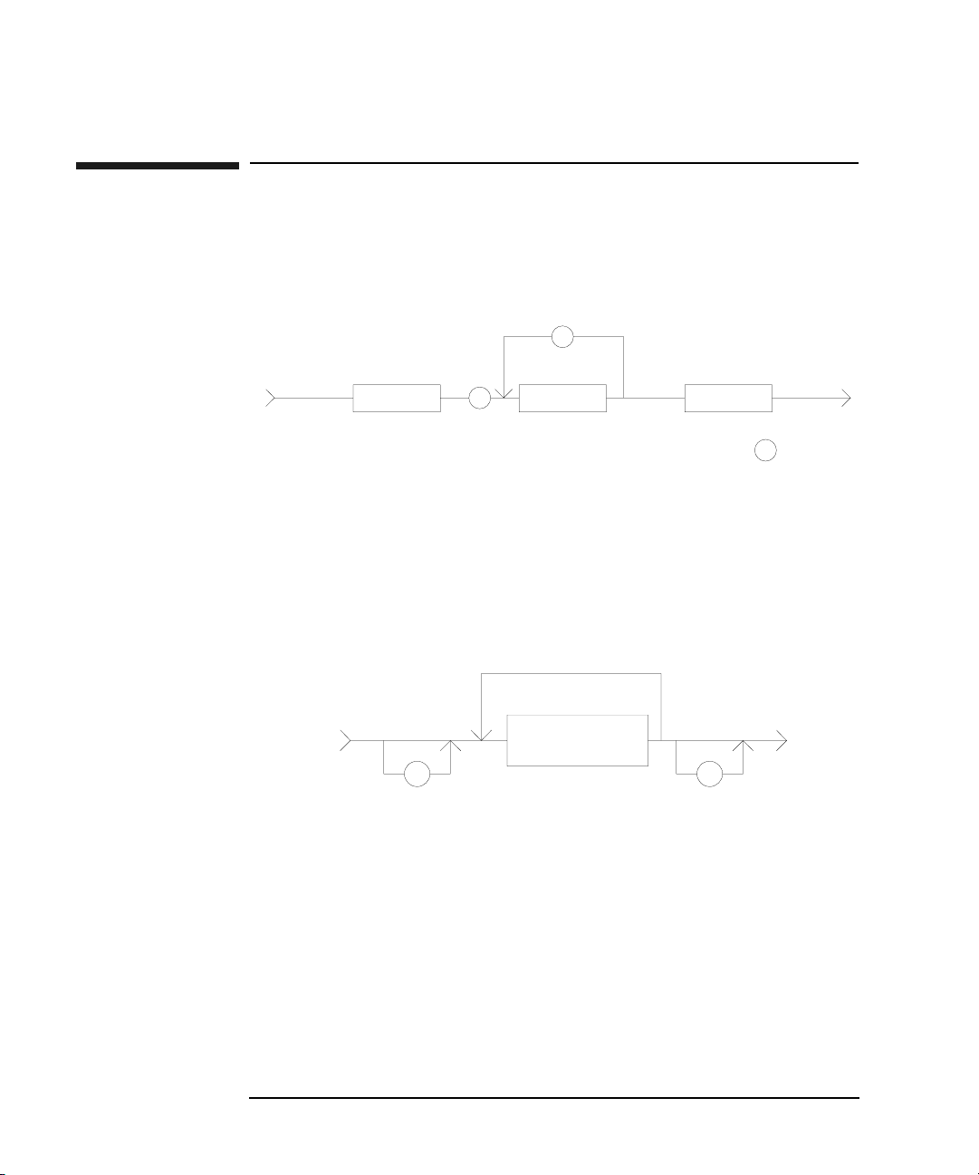
The 4155C/4156C FLEX commands are composed of a header, numeric data, and
terminator, as shown in the syntax diagram in the following figure.
4155C/4156C Control Command Syntax Diagram
Header
The header is the command name, always contains alpha characters, and is not
upper or lowercase sensitive. Some command names also contain an asterisk (*) or
question mark (?). The following figure shows the syntax diagram for a header.
Header Syntax Diagram
1-8 Agilent 4155C/4156C GPIB Command Reference, Edition 1

4155C/4156C FLEX Commands
Numeric Data
Numeric Data
Numeric data is the command parameters. You need to insert a space between the
header and the command parameters (numeric data). Some parameters require
integer data. The following figure shows the syntax diagram for numeric data.
Numeric Data Syntax Diagram
The following 3 figures show the syntax diagrams for integer, fixed point, and
floating point data, respectively.
Integer Data Syntax Diagram
Fixed Point Data Syntax Diagram
Floating Point Data Syntax Diagram
Agilent 4155C/4156C GPIB Command Reference, Edition 1 1- 9

4155C/4156C FLEX Commands
Terminator
Terminator
The terminator completes the GPIB command entry and starts command execution.
The following figure shows the terminator syntax diagram.
Terminator Syntax Diagram
%4
.(
.(
'1+
(
Special Terminator
If a semicolon (;) is inserted before the terminator, as shown in the following figure,
the preceding commands are not executed until the next command line is input and
another terminator is input, without a preceding semicolon. The command lines are
then executed together.
Special Terminator
%4
.(
.(
'1+
@
1-10 Agilent 4155C/4156C GPIB Command Reference, Edition 1

4155C/4156C FLEX Commands
Conventions
Data Output Format
This section describes the data output formats of the 4155C/4156C. The
4155C/4156C provides the following four types of data output formats:
•“ASCII Format in US Mode”
•“Binary Format in US Mode”
•“ASCII Format in US42 Mode”
•“Binary Format in US42 Mode”
You can select the data output format using the FMT command. See the FMT
command for more information.
Conventions
The following conventions are used in the data output format tables (Table 1-1
through Table 1-4).
Data Output data that the 4155C/4156C sends after a measurement.
[Data] Optional output data that is sent when there are multiple output
data. See FMT command. For example, after the sampling
measurements when the sampling point index output is
specified by the FMT command.
Time Stamp Function
The time stamp function is used to record the start time of the measurement. When
this function is enabled, the 4155C/4156C output data includes the time data (Time).
For example, in the staircase sweep measurements, the output data will be as
follows:
Block1 [,Block2] . . . . <terminator>
where, BlockN (N: integer) = Time1,Data1 [,Time2,Data2] ... [,Source_data]
TimeN (N: integer) is the time from the point the count is cleared until the start of the
DataN measurement.
The time stamp function is not available for the quasi-static CV measurements,
linear search measurements, and binary search measurements in the US control
mode. It is not available for any measurement in the US42 control mode.
Agilent 4155C/4156C GPIB Command Reference, Edition 1 1-11

4155C/4156C FLEX Commands
ASCII Format in US Mode
ASCII Format in US Mode
Table 1-1 shows the ASCII data output format in control mode set by the US
command. The format used depends on the measurement mode selected.
Table 1-1 ASCII Data Output Format in US Control Mode
Measurement Mode Output Format
Stress Force
High Speed Spot
Spot
1ch Pulsed Spot
Staircase Sweep,
Pulsed Sweep,
Staircase Sweep with
Pulsed Bias
Status <terminator>
a
Status is the status information sent after a stress force.
Data <terminator>
a
Data is the data measured by the measurement unit
specified for the high speed spot measurement using the
MM command.
Data1 [,Data2] . . . . <terminator>
a
DataN (N: integer) is the data measured by one unit.
The order of Data is specified by the MM command.
Data <terminator>
a
Data is the data measured by the measurement unit
specified for the pulsed spot measurement using the
MM command.
Block1 [,Block2] ....<terminator>
a
Block1 is the block of data measured at the first sweep
step. Block2 is the block of data measured at the second
sweep step.
where Block consists of the following data:
Data1 [,Data2]....[,Source_data]
DataN (N: integer) is the data measured by one unit.
The order of Data is specified by the MM command.
Source_data is the source data at the sweep step.
a. Terminator. <LF^EOI> or <,^EOI>, depending on the FMT command
parameter. See FMT command.
1-12 Agilent 4155C/4156C GPIB Command Reference, Edition 1

4155C/4156C FLEX Commands
ASCII Format in US Mode
Measurement
Mode
Sampling
Output Format
Block1 [,Block2] . . . . <terminator>
a
Block1 is the block of the data measured at the first sampling
point.
Block2 is the block of the data measured at the second
sampling point.
where Block consists of the following data:
[Sampling_no,] Data1 [,Data2] . . . .
Sampling_no is the sampling point index. This value depends
on the sampling interval setting and the measurement time.
If the measurement time is shorter than the sampling interval,
Sampling_no will be N of BlockN (N: 1, 2, 3 . . . ).
If the measurement time is longer than the sampling interval,
Sampling_no is not N of BlockN.
For example, if the measurement time is longer than the
sampling interval and shorter than twice the sampling interval,
then the Sampling_no is 2 for Block1, and 4 for Block2.
The measurement time depends on the settings of the AV, AZ,
SIT and SLI commands.
DataN (N: integer) is the data measured by one unit. The order
of Data is specified by the MM command.
The Sampling_no and Data values can be discarded when the
range changes in the auto or limited auto ranging mode.
a. Terminator. <LF^EOI> or <,^EOI>, depending on the FMT command
parameter. See FMT command.
Agilent 4155C/4156C GPIB Command Reference, Edition 1 1-13

4155C/4156C FLEX Commands
ASCII Format in US Mode
Measurement Mode Output Format
Quasi-static CV
Linear search,
Binary search
Block1 [,Block2] ....<terminator>
a
Block1 is the data of the first measurement point.
Block2 is the data of the second point.
where Block consists of the following data:
[DataL,] DataC [,Source_data]
DataL is the leakage current measurement data.
DataC is the capacitance measurement data.
Source_data is the source output voltage.
DataL is set by the QSL command.
[D1,D2 . . . ,] Search,Source_data,Data <terminator>
Search is the search status. Source_data is the source
output data of the search target.
Data is the measurement data of the search target.
D1 is the data of the first measurement point.
D2 is the data of the second point.
where Dn (n: integer) consists of the following data:
Source_data,Data
Source_data is the source output data.
Data is the measurement data.
a
Dn is set by the BSVM command for the binary search,
or LSVM command for the linear search.
a. Terminator. <LF^EOI> or <,^EOI>, depending on the FMT command
parameter. See FMT command.
1-14 Agilent 4155C/4156C GPIB Command Reference, Edition 1

4155C/4156C FLEX Commands
ASCII Format in US Mode
Output Data The 4155C/4156C sends the measurement data (Data), source output data
(Source_data), sampling point index (Sampling_no), time data (Time) or status
information (Search or Status) in the format specified by the FMT 1, FMT 2, or
FMT 5 command.
• ASCII format with header (output by FMT 1 or FMT 5):
AAABCDDDDDDDDDDDDD
• ASCII format without header (output by FMT 2):
DDDDDDDDDDDDD
where,
A: Status.
B: Channel number.
C: Data type.
D: Data.
NOTE For Sampling_no, ignore B.
For Time, ignore A.
For Search, ignore A and B.
For Status, ignore B and D.
They are not valid for the output data.
Agilent 4155C/4156C GPIB Command Reference, Edition 1 1-15

4155C/4156C FLEX Commands
ASCII Format in US Mode
The A, B, C, and D values are explained below.
A : Status; 3 digits.
• Status for Source_data:
AAA Explanation
W Data is for the first or intermediate sweep step.
E Data is for the last sweep step.
• Status for Data, Sampling_no, or Status:
AAA Explanation
1 A/D converter overflowed.
2 One or more units are oscillating.
4 Another unit reached its compliance setting.
8 This unit reached its compliance setting.
Integration time too short for capacitance measurement.
16 The PGU reached its compliance setting.
32 The sweep measurement was stopped by the ESC stop
condition. Returned data is effective.
64 Invalid data is returned. D is not used.
128 EOD (End of Data).
If multiple status conditions are found, the sum of the AAA values is
returned. For example, if an A/D converter overflow occurred, and
an SMU was oscillating during the measurements, the returned AAA
value is 3 (1 + 2).
1-16 Agilent 4155C/4156C GPIB Command Reference, Edition 1

4155C/4156C FLEX Commands
ASCII Format in US Mode
B : Channel number of the measurement/source unit; 1 digit.
B Explanation
A Channel number 1, SMU1.
B Channel number 2, SMU2.
C Channel number 3, SMU3.
D Channel number 4, SMU4.
E Channel number 5, SMU5 (in 41501A/B).
F Channel number 6, SMU6 (in 41501A/B).
Q Channel number 21, VSU1.
R Channel number 22, VSU2.
S Channel number 23, VMU1.
T Channel number 24, VMU2.
V Channel number 26, GNDU (in 41501A/B).
W Channel number 27, PGU1 (in 41501A/B).
X Channel number 28, PGU2 (in 41501A/B).
Z Returned D value is not measurement data.
C : Data type; 1 digit.
C Explanation
V Voltage measurement data (Data).
v Voltage source setup data (Setup_data).
I Current measurement data (Data).
i Current source setup data (Setup_data).
C Capacitance measurement data (Data).
p Sampling point index (Sampling_no).
T Time data (Time).
S Status information (Search or Status).
Z Invalid data is returned.
z
Agilent 4155C/4156C GPIB Command Reference, Edition 1 1-17

4155C/4156C FLEX Commands
ASCII Format in US Mode
D : Data; 13 digits.
Value of Data, Source_data, Sampling_no, and Time may be one of the
following:
• sn.nnnnnnEsnn
• snn.nnnnnEsnn
• snnn.nnnnEsnn
where,
s: Sign, + or -.
n: Digit, 0 to 9.
E: Exponent symbol.
Value of Search:
D Description
0 No error.
1 Measurement aborted, but cannot specify the reason. Ignore
Source_data and Data.
10 No target found in the specified search range of the binary
search. Data at the start or stop near the target value is set to
Source_data and Data.
11 No target found in the limit mode binary search. The last
search data is set to Source_data and Data.
12 Over-range at the synchronous output channel in the binary
search. Ignore Source_data and Data.
20 No target found in the linear search. Ignore Source_data
and Data.
21 Over-range at the synchronous output channel in the linear
search. Ignore Source_data and Data.
22 Abort condition occurred in the linear search. Ignore
Source_data and Data. The status of the Data is AAA=192.
In all data output modes (LSVM 1), the status code is set to
the status of the last measurement data.
The abort condition is set by the WM command.
1-18 Agilent 4155C/4156C GPIB Command Reference, Edition 1

4155C/4156C FLEX Commands
Binary Format in US Mode
Table 1-2 shows the binary data output format in control mode set by the US
command. The format used depends on the measurement mode selected.
Table 1-2 Binary Data Output Format in US Control Mode
Measurement Mode Output Format
Binary Format in US Mode
Stress Force
High Speed Spot
Spot
1ch Pulsed Spot
Staircase Sweep,
Pulsed Sweep,
Staircase Sweep with
Pulsed Bias
Status <terminator>
a
Status is the status information sent after a stress force.
Data <terminator>
a
Data is the data measured by the measurement unit
specified for the high speed spot measurement using
the MM command.
Data1 [Data2] . . . . <terminator>
a
DataN (N: integer) is the data measured by one unit.
The order of Data is specified by the MM command.
Data <terminator>
a
Data is the data measured by the measurement unit
specified for the pulsed spot measurement using the
MM command.
Block1 [Block2] . . . . <terminator>
a
Block1 is the block of data measured at the first sweep
step. Block2 is the block of data measured at the second
sweep step.
where Block consists of the following data:
Data1 [Data2] . . . . [Source_data]
DataN (N: integer) is the data measured by one unit.
The order of Data is specified by the MM command.
Source_data is the source data at the sweep step.
a. Terminator. <LF^EOI> or <,^EOI>, depending on the FMT command
parameter. See FMT command.
Agilent 4155C/4156C GPIB Command Reference, Edition 1 1-19

4155C/4156C FLEX Commands
Binary Format in US Mode
Measurement Mode Output Format
Sampling
Block1 [Block2] . . . . <terminator>
a
Block1 is the block of the data measured at the first
sampling point.
Block2 is the block of the data measured at the second
sampling point.
where Block consists of the following data:
[Sampling_no] Data1 [Data2] . . . .
Sampling_no is the sampling point index. This value
depends on the sampling interval setting and the
measurement time.
If the measurement time is shorter than the sampling
interval, Sampling_no will be N of BlockN (N: 1, 2, 3
. . . ).
If the measurement time is longer than the sampling
interval, Sampling_no is not N of BlockN.
For example, if the measurement time is longer than
the sampling interval and shorter than twice the
sampling interval, then the Sampling_no is 2 for
Block1, and 4 for Block2.
The measurement time depends on the settings of the
AV, AZ, SIT and SLI commands.
DataN (N: integer) is the data measured by one unit.
The order of Data is specified by the MM command.
The Sampling_no and Data values can be discarded
when the range changes in the auto or limited auto
ranging mode.
a. Terminator. <LF^EOI> or <,^EOI>, depending on the FMT command
parameter. See FMT command.
1-20 Agilent 4155C/4156C GPIB Command Reference, Edition 1

4155C/4156C FLEX Commands
Binary Format in US Mode
Measurement Mode Output Format
Quasi-static CV
Linear search,
Binary search
Block1 [Block2] . . . . <terminator>
a
Block1 is the data of the first measurement point.
Block2 is the data of the second point.
where Block consists of the following data:
[DataL,] DataC [,Source_data]
DataL is the leakage current measurement data.
DataC is the capacitance measurement data.
Source_data is the source output voltage.
DataL is set by the QSL command.
[D1 D2 . . . ] Search Source_data Data <terminator>
Search is the search status. Source_data is the source
output data of the search target.
Data is the measurement data of the search target.
D1 is the data of the first measurement point.
D2 is the data of the second point.
where Dn (n: integer) consists of the following data:
Source_data Data
Source_data is the source output data.
Data is the measurement data.
a
Dn is set by the BSVM command for the binary search,
or LSVM command for the linear search.
a. Terminator. <LF^EOI> or <,^EOI>, depending on the FMT command
parameter. See FMT command.
Agilent 4155C/4156C GPIB Command Reference, Edition 1 1-21

4155C/4156C FLEX Commands
Binary Format in US Mode
Output Data The 4155C/4156C sends the measurement data (Data), source output data
(Source_data), sampling point index (Sampling_no), time data (Time), or status
information (Search or Status) in the format specified by the FMT 3 or FMT 4
command.
The binary data is six (6) bytes long, and consists of some blocks as shown below:
For Data, Source_data, Sampling_no, Search, Status:
Byte1
65432107 65432107 65432107 65432107 65432107 65432107
BC D E F
A
Byte 2
Byte 3
Byte 4
Byte 5
For Time:
Byte1 Byte 2 Byte 3 Byte 4 Byte 5 Byte 6
65432107 65432107 65432107 65432107 65432107 65432107
AB G F
where,
A: Measurement or source output data type.
B: Data type.
C: Measurement or output range.
D: Data.
E: Status.
F: Channel number.
G: Time data.
NOTE For Sampling_no, ignore A, C, and F.
Byte 6
For Search, ignore A, C, E and F.
For Status, ignore A, C, D, and F.
For Time, ignore A.
They are not valid for the output data.
1-22 Agilent 4155C/4156C GPIB Command Reference, Edition 1

4155C/4156C FLEX Commands
Binary Format in US Mode
The A, B, C, D, E, F, and G values are explained below.
A : Measurement or source output data type; one bit.
A Explanation
0 Source output data.
1 Measurement data.
B : Data type; three bits.
B Explanation
000 Voltage data.
001 Current data.
010 Capacitance data.
011 Time data.
110 Sampling point index.
111 Status information.
C : Measurement or output range; five bits.
C Explanation
01001 10 pA or 10 pF
01010 0.2 V or 100 pA or 100 pF
01011 2 V or 1 nA or 1 nF
01100 20 V or 10 nA or 10 nF
01101 40 V or 100 nA or 100nF
01110 100 V or 1 mA or 1 mF
01111 200 V or 10 mA or 10 mF
10000 100 mA or 100 mF
10001 1 mA or 1 mF
10010 10 mA or 10 mF
Agilent 4155C/4156C GPIB Command Reference, Edition 1 1-23

4155C/4156C FLEX Commands
Binary Format in US Mode
C Explanation
10011 100 mA or 100 mF
10100 1 A or 1 F
11111 Invalid data is returned.
D : Value of Data, Source_data, or Sampling_no; 26 bits.
This value is expressed as 26-bit binary data. It is used to calculate the
measurement data or source output data, using the equations shown
below. For Sampling_no, this value is the binary expression of the
value. You do not need the following equations.
Equations:
Measurement data = Count ´ Range /1000000
Source output data = Count ´ Range /20000
where, Count is the decimal value of D, and Range is the value
indicated by C.
If the top bit of the 26-bit binary data is 0, the Count is positive and
equal to the decimal value of the 25-bit binary data that follows the top
bit.
If the top bit is 1, the measurement data is negative. Calculate the Count
by subtracting 33554432 (10000000000000000000000000 in binary)
from the decimal value of the 25-bit binary data.
Example:
If the output binary data is:
100101010000000000000000110000001001000000000001
then,
Data type: Current measurement data (A=1, B=001)
Range: 100 pA (C=01010)
Count: 1540 (D=00000000000000011000000100)
Statu s: EOD (E=10000000)
Channel: SMU1 (channel number 1) (F=00001)
Measurement data = 1540
´ 100E–12/1E+6 = 154 fA
1-24 Agilent 4155C/4156C GPIB Command Reference, Edition 1

4155C/4156C FLEX Commands
Binary Format in US Mode
Value of Search; 26 bits. The following table shows lower 5 bits.
D Description
00000 No error.
00001 Measurement aborted, but cannot specify the reason.
Ignore Source_data and Data.
01010 No target found in the specified search range of the
binary search.
Data at the start or stop near the target value is set to
Source_data and Data.
01011 No target found in the limit mode binary search.
The last search data is set to Source_data and Data.
01100 Over-range at the synchronous output channel in the
binary search.
Ignore Source_data and Data.
10100 No target found in the linear search.
Ignore Source_data and Data.
10101 Over-range at the synchronous output channel in the
linear search.
Ignore Source_data and Data.
10110 Abort condition occurred in the linear search.
Ignore Source_data and Data.
Status of Data is E=11000000.
In all data output modes (LSVM 1), the status code is set
to the status of the last measurement data.
An abort condition is set by the WM command.
Agilent 4155C/4156C GPIB Command Reference, Edition 1 1-25

4155C/4156C FLEX Commands
Binary Format in US Mode
E : Status; eight bits.
• Status for Source_data:
E Explanation
00000001 Data is for the first or intermediate sweep step.
00000010 Data is for the last sweep step.
• Status for Data, Sampling_no, or Status:
E Explanation
00000001 A/D converter overflowed.
00000010 One or more units are oscillating.
00000100 Another unit reached its compliance setting.
00001000 This unit reached its compliance setting.
Integration time too short for capacitance
measurement.
00010000 The PGU reached its compliance setting.
00100000 Sweep measurement was stopped by the ESC stop
condition. The returned data is effective.
01000000 Invalid data is returned. D is not valid.
10000000 EOD (End of Data).
If multiple status conditions are found, the sum of the status values
is returned. For example, if an A/D converter overflow occurred
and an SMU was oscillating during the measurements, the returned
value is 00000011 (00000001+00000010).
F : Channel number of the measurement/source unit; five bits.
F Explanation
00001 Channel number 1, SMU1.
00010 Channel number 2, SMU2.
00011 Channel number 3, SMU3.
00100 Channel number 4, SMU4.
1-26 Agilent 4155C/4156C GPIB Command Reference, Edition 1

F Explanation
00101 Channel number 5, SMU5 (in 41501A/B).
00110 Channel number 6, SMU6 (in 41501A/B).
10101 Channel number 21, VSU1.
10110 Channel number 22, VSU2.
10111 Channel number 23, VMU1.
11000 Channel number 24, VMU2.
11010 Channel number 26, GNDU (in 41501A/B).
11011 Channel number 27, PGU1 (in 41501A/B).
11100 Channel number 28, PGU2 (in 41501A/B).
11111 Invalid data is returned.
G : Value of Ti m e; 39 bits.
4155C/4156C FLEX Commands
Binary Format in US Mode
This value is expressed in 39-bit binary data. It is used to calculate the
time data, using the equations shown below.
Equations:
Time data = Count ´ 100 ms
where, Count is the decimal value of G.
Example:
If the output binary data is:
001100000000000000000000100100100111110000000001
then,
Data type: Time data (A=0, B=011)
Count: 300000 (D=1001001001111100000)
Channel: SMU1 (channel number 1) (F=00001)
Measurement data = 300000
´ 100E–6 = 30 s
Agilent 4155C/4156C GPIB Command Reference, Edition 1 1-27

4155C/4156C FLEX Commands
ASCII Format in US42 Mode
ASCII Format in US42 Mode
Table 1-3 shows the ASCII data output format in control mode set by the US42
command. The format used depends on the measurement mode selected.
Table 1-3 ASCII Data Output Format in US42 Control Mode
Measurement Mode Output Format
Stress Force
High Speed Spot
Spot
1ch Pulsed Spot
Staircase Sweep
a
Status <terminator>
Status is the status information sent after a stress force.
Data <terminator>
a
Data is the data measured by the measurement unit
specified for the high speed spot measurement using
the MM command.
Data1 [,Data2] . . . . <terminator>
a
DataN (N: integer) is the data measured by one unit.
The order of Data is specified by the MM command.
Data <terminator>
a
Data is the data measured by the measurement unit
specified for the pulsed spot measurement using the
MM command.
Block1 [,Block2] . . . . <terminator>
a
Block1 is the block of data measured at the first sweep
step. Block2 is the block of data measured at the second
sweep step.
where Block consists of the following data:
Data1 [,Data2] . . . . [,Source_data]
DataN (N: integer) is the data measured by one unit.
The order of Data is specified by the MM command.
Source_data is the source data at the sweep step.
a. Terminator. <CR/LF^EOI>, <^EOI> or , (comma), depending on the
FMT command parameter. See FMT command.
1-28 Agilent 4155C/4156C GPIB Command Reference, Edition 1

4155C/4156C FLEX Commands
ASCII Format in US42 Mode
Measurement Mode Output Format
Pulsed Sweep,
Block1 [,Block2] . . . . <terminator>
Staircase Sweep with
Pulsed Bias
Block1 is the block of data measured at the first sweep
step. Block2 is the block of data measured at the second
sweep step.
where Block consists of the following data:
Data [,Source_data]
Data is the measurement data. Source_data is the
source data at the sweep step.
Sampling
Block1 [,Block2] . . . . <terminator>
Block1 is the block of the data measured at the first
sampling point. Block2 is the block of the data
measured at the second sampling point.
where Block consists of the following data:
[Sampling_no,] Data1 [,Data2] . . . .
Sampling_no is the sampling point index. This value
depends on the sampling interval setting and the
measurement time.
a
a
If the measurement time is shorter than the sampling
interval, the Sampling_no will be N of BlockN (N: 1, 2,
3 . . . ). If the measurement time is longer than the
sampling interval, the Sampling_no is not N of BlockN.
For example, if the measurement time is longer than
the sampling interval and shorter than twice the
sampling interval, then the Sampling_no is 2 for
Block1, and 4 for Block2.
The measurement time depends on the settings of the
AV, AZ, SIT and SLI commands.
DataN (N: integer) is the data measured by one unit.
The order of Data is specified by the MM command.
The Sampling_no and Data values can be discarded
when the range changes in the auto or limited auto
ranging mode.
a. Terminator. <CR/LF^EOI>, <^EOI> or , (comma), depending on the
FMT command parameter. See FMT command.
Agilent 4155C/4156C GPIB Command Reference, Edition 1 1-29

4155C/4156C FLEX Commands
ASCII Format in US42 Mode
Output Data The 4155C/4156C sends the measurement data (Data), source output data
(Source_data), sampling point index (Sampling_no), or stress status information
(Status) in the format specified by the FMT 1, FMT 2, or FMT 5 command.
• ASCII format with header (output by FMT 1 or FMT 5):
ABCDDDDDDDDDDDD
where no space is included between the parameters.
• ASCII format without header (output by FMT 2):
DDDDDDDDDDDD
where,
A: Status.
B: Channel number.
C: Data type.
D: Data.
NOTE If the output data is Sampling_no, ignore B.
If the output data is Status, ignore B and D.
They are not valid for the output data.
The A, B, C, and D values are explained below.
A : Status; 1 digit.
• Status for Data, Sampling_no, or Status:
A Explanation
N No status error occurred.
T Another unit reached its compliance setting.
C This unit reached its compliance setting.
V Measurement data is over the measurement range.
X One or more units are oscillating.
1-30 Agilent 4155C/4156C GPIB Command Reference, Edition 1

4155C/4156C FLEX Commands
ASCII Format in US42 Mode
• Status for Source_data:
A Explanation
W Data is for the first or intermediate sweep step.
E Data is for the last sweep step.
B : Channel number of the measurement/source unit; 1 digit.
B Explanation
A Channel number 1, SMU1.
B Channel number 2, SMU2.
C Channel number 3, SMU3.
D Channel number 4, SMU4.
E Channel number 5, SMU5 (in 41501A/B).
F Channel number 6, SMU6 (in 41501A/B).
Q Channel number 21, VSU1.
R Channel number 22, VSU2.
S Channel number 23, VMU1.
T Channel number 24, VMU2.
V Channel number 26, GNDU (in 41501A/B).
W Channel number 27, PGU1 (in 41501A/B).
X Channel number 28, PGU2 (in 41501A/B).
Z Returned D value is not measurement data.
Agilent 4155C/4156C GPIB Command Reference, Edition 1 1-31

4155C/4156C FLEX Commands
ASCII Format in US42 Mode
C : Data type; 1 digit.
C Explanation
V Voltage measurement data.
v Voltage source setup data.
I Current measurement data.
i Current source setup data.
p Sampling point index.
S Status information.
Z Invalid data is returned.
z
D Value of Data, Source_data, or Sampling_no; 12 digits, which may be
one of the following:
• sn.nnnnnEsnn
• snn.nnnnEsnn
• snnn.nnnEsnn
where,
s: Sign, + or -.
n: Digit, 0 to 9.
E: Exponent symbol.
1-32 Agilent 4155C/4156C GPIB Command Reference, Edition 1

4155C/4156C FLEX Commands
Binary Format in US42 Mode
Binary Format in US42 Mode
Table 1-4 shows the binary data output format in control mode set by the US42
command. The format used depends on the measurement mode selected.
Table 1-4 Binary Data Output Format in US42 Control Mode
Measurement Mode Output Format
Stress Force
High Speed Spot
Spot
1ch Pulsed Spot
Staircase Sweep
a
Status <terminator>
Status is the status information sent after a stress force.
Data <terminator>
a
Data is the data measured by the measurement unit
specified for the high speed spot measurement using the
MM command.
Data1 [Data2] . . . . <terminator>
a
DataN (N: integer) is the data measured by one unit.
The order of Data is specified by the MM command.
Data <terminator>
a
Data is the data measured by the measurement unit
specified for the pulsed spot measurement using the
MM command.
Block1 [Block2] . . . . <terminator>
a
Block1 is the block of data measured at the first sweep
step. Block2 is the block of data measured at the second
sweep step.
where Block consists of the following data:
Data1 [Data2] . . . . [Source_data]
DataN (N: integer) is the data measured by one unit.
The order of Data is specified by the MM command.
Source_data is the source data at the sweep step.
a. Terminator. <CR/LF^EOI>, <^EOI> or , (comma), depending on the
FMT command parameter. See FMT command.
Agilent 4155C/4156C GPIB Command Reference, Edition 1 1-33

4155C/4156C FLEX Commands
Binary Format in US42 Mode
Measurement Mode Output Format
Pulse Sweep,
Block1 [Block2] . . . . <terminator>
Staircase Sweep with
Pulsed Bias
Block1 is the block of data measured at the first sweep
step. Block2 is the block of data measured at the second
sweep step.
where Block consists of the following data:
Data [Source_data]
Data is the measurement data. Source_data is the
source data at the sweep step.
Sampling
Block1 [Block2] . . . . <terminator>
Block1 is the block of the data measured at the first
sampling point. Block2 is the block of the data
measured at the second sampling point.
where Block consists of the following data:
[Sampling_no] Data1 [Data2] . . . .
Sampling_no is the sampling point index. This value
depends on the sampling interval setting and the
measurement time.
a
a
If the measurement time is shorter than the sampling
interval, then the Sampling_no will be N of BlockN (N:
1, 2, 3 . . . ). If the measurement time is longer than the
sampling interval, then the Sampling_no is not N of
BlockN. For example, if the measurement time is
longer than the sampling interval and shorter than
twice the sampling interval, the Sampling_no is 2 for
Block1, and 4 for Block2.
The measurement time depends on the settings of the
AV, AZ, SIT and SLI commands.
DataN (N: integer) is the data measured by one unit.
The order of Data is specified by the MM command.
The Sampling_no and Data values can be discarded
when the range changes in the auto or limited auto
ranging mode.
a. Terminator. <CR/LF^EOI>, <^EOI> or , (comma), depending on the
FMT command parameter. See FMT command.
1-34 Agilent 4155C/4156C GPIB Command Reference, Edition 1

4155C/4156C FLEX Commands
Binary Format in US42 Mode
Output Data The 4155C/4156C sends the measurement data (Data), source output data
(Source_data), sampling point index (Sampling_no), or status information (Status)
in the format specified by the FMT 3 or FMT 4 command.
Binary data is four bytes long, and consists of six blocks (A, B, C, D, E and F) as
shown below:
Byte 1 Byte 2 Byte 3 Byte 4
65432107 65432107 65432107 65432107
AB C D E F
where,
A: Measurement or source output data type.
B: Data type.
C: Measurement or output range.
D: Data.
E: Status.
F: Channel number.
NOTE If the output data is Sampling_no, ignore A, B, C, and F.
If the output data is Status, ignore A, B, C, D, and F.
They are not valid for the output data.
The A, B, C, and D values are explained below.
A : Measurement or source output data type; one bit.
A Explanation
0 Source output data.
1 Measurement data.
B : Data type; one bit.
B Explanation
0 Voltage data.
1 Current data.
Agilent 4155C/4156C GPIB Command Reference, Edition 1 1-35

4155C/4156C FLEX Commands
Binary Format in US42 Mode
C : Measurement or output range; five bits.
C Explanation
01010 0.2 V range.
01011 2 V or 1 nA range.
01100 20 V or 10 nA range.
01101 40 V or 100 nA range.
01110 100 V or 1 mA range.
01111 200 V or 10 mA range.
10000 100 mA range.
10001 1 mA range.
10010 10 mA range.
10011 100 mA range.
10100 1 A range.
11111 Invalid data is returned.
D : Value of Data, Source_data, or Sampling_no parameter. This value is
expressed in 17-bit binary data. It is used to calculate the measurement
data or source output data using the following equations.
For Sampling_no, this value is the binary expression of the sampling
measurement point index value. You do not need the following
equations.
Equations:
Measurement data = Count ´ Range /50000
Source output data = Count ´ Range /20000
where, Count is the decimal value of D, and Range is the measurement
range or output range indicated by C.
If the top bit of the 17-bit binary data is 0, the Count is positive and
equal to the decimal value of the 16-bit binary data that follows the top
bit.
If the top bit is 1, the measurement data is negative. Calculate the Count
by subtracting 65536 (10000000000000000 in binary) from the decimal
value of the 16-bit binary data.
1-36 Agilent 4155C/4156C GPIB Command Reference, Edition 1

Example:
If the output binary data is:
11010110000100111000100000000001
then,
Data type: Current measurement data (A=1, B=1)
Range: 1 nA (C=01011)
Count: 5000 (D=00001001110001000)
Statu s: Normal condition (E=000)
Channel: SMU1 (channel number 1) (F=00001)
4155C/4156C FLEX Commands
Binary Format in US42 Mode
Measurement data = 5000
E : Status; three bits.
• Status for Data, Sampling_no, or Status:
E Explanation
000 No status error occurred.
001 Another unit reached its compliance setting.
010 This unit reached its compliance setting.
011 Measurement data is over the measurement range.
100 One or more units are oscillating.
• Status for Source_data:
E Explanation
001 Data is for the first or intermediate sweep step.
010 Data is for the last sweep step.
´ 1E–9/5E+4 = 100 pA
Agilent 4155C/4156C GPIB Command Reference, Edition 1 1-37

4155C/4156C FLEX Commands
Binary Format in US42 Mode
F : Channel number of the measurement/source unit; five bits.
F Explanation
00001 Channel number 1, SMU1.
00010 Channel number 2, SMU2.
00011 Channel number 3, SMU3.
00100 Channel number 4, SMU4.
00101 Channel number 5, SMU5 (in 41501A/B).
00110 Channel number 6, SMU6 (in 41501A/B).
10101 Channel number 21, VSU1.
10110 Channel number 22, VSU2.
10111 Channel number 23, VMU1.
11000 Channel number 24, VMU2.
11010 Channel number 26, GNDU (in 41501A/B).
11011 Channel number 27, PGU1 (in 41501A/B).
11100 Channel number 28, PGU2 (in 41501A/B).
11111 Invalid data is returned.
1-38 Agilent 4155C/4156C GPIB Command Reference, Edition 1

Status Byte
This section provides the status byte information for the 4155C/4156C in the FLEX
command control mode. The information depends on whether the control mode is
set by US command or US42 command. See Table 1-5 and Table 1-6. The status
byte bit assignment shown in Table 1-6 is identical to the 4142B definition.
Table 1-5 In the US Command Mode
Bit Description
0 Emergency Status
Indicates whether any emergency has occurred. If the instrument is in
the emergency status, this bit is set to 1.
1 Measurement/Stress Status
Indicates whether the measurement/stress force has been executed. If
the instrument is in the measurement/stress status, this bit is set to 1.
4155C/4156C FLEX Commands
Binary Format in US42 Mode
2not used
3 Questionable Status
Indicates whether output buffer is empty. If an unread query response
exists, this bit is set to 1.
4 MAV (Message Available summary-message)
Indicates whether output buffer is empty. If an unread message exists,
this bit is set to 1.
5 ESB (Event Status Bit)
Shows the logical ORed value of the error summary register bits.
6 Request Service (RQS) Message
Indicates whether an SRQ (Service Request) has occurred. You cannot
mask this bit.
7not used
Agilent 4155C/4156C GPIB Command Reference, Edition 1 1-39

4155C/4156C FLEX Commands
Binary Format in US42 Mode
Table 1-6 In the US42 Command Mode
Bit Description
0 Data Ready
Indicates whether the output buffer is empty. If unread data exists, this
bit is set to 1.
1 Wait
Indicates whether the instrument is in the wait status. If instrument is in
the wait state, this bit is set to 1.
2not used
3 Interlock Open
If the interlock circuit is open, and an output voltage over ±40 V is
applied, this bit is set to 1.
4 Set Ready
Indicates whether an GPIB command or external trigger has been sent.
If GPIB command execution or the operation by external trigger is
completed, this bit is set to 1.
5Error
Indicates whether any error has occurred. If any error occurred, this bit
is set to 1.
6 RQS (You cannot mask this bit.)
Indicates whether an SRQ (Service Request) has occurred.
7 Shutdown
If the instrument turned off by itself, to avoid damage, or instantaneous
power down occurred on the site power line, this bit is set to 1.
The status byte register can be read with either a serial poll or the *STB? query
command.
Serial poll is a low-level GPIB command that can be executed by the SPOLL
command in HP BASIC, as follows:
Status=SPOLL(@Hp4156)
In general, use serial polling (not *STB?) inside interrupt service routines.
Use *STB? in other cases (not in interrupt service routine) when you want to know
the value of the Status Byte.
1-40 Agilent 4155C/4156C GPIB Command Reference, Edition 1

4155C/4156C FLEX Commands
Binary Format in US42 Mode
Command Reference
This section contains detailed descriptions of each command. The commands are
listed in alphabetical order. Each entry:
1. Defines one GPIB command
2. Describes the execution conditions, if any exist
3. Describes the syntax
4. Lists the parameters
5. Shows the query response after command execution, if there is a query
command
6. Explains any additional information
7. Provides examples
The following conventions are used in this section.
parameter Required command parameters, for which you must substitute a
value or variable.
[parameter] Optional command parameters, for which you may substitute a
value or omit it.
Agilent 4155C/4156C GPIB Command Reference, Edition 1 1-41

4155C/4156C FLEX Commands
Binary Format in US42 Mode
Category Command Summary
Reset *RST Resets the 4155C/4156C to the initial settings, and clears the zero offset data.
Self-test *TST? Starts the self-test.
Control Mode US Enters the 4155C/4156C FLEX command control mode.
US42 Enters the 4155C/4156C FLEX command control mode. This mode provides the
4142B-like response (data output, terminator, and so on).
ACH Used with the US42 command to assign the channel numbers used in the
measurement programs for the 4142B to the channel numbers available for the
4155C/4156C.
:PAGE Returns to the 4155C/4156C SCPI command control mode.
Unit Control CN Enables the specified units by setting the output switches to ON.
CL Disables the specified units by setting the output switches to OFF.
FL Sets the filter of specified units to ON or OFF.
IN Sets the specified units to zero output.
DZ Stores the measurement setup of the units, and sets the units to Zero (0 V) Output.
RZ Returns the unit to the settings that are stored by the DZ command and clears the
stored unit settings.
RCV Enables the units that fail self-test.
Measurement
Mode
dc Source
Setup
SMU Pulse
Setup
MM Sets the measurement mode and measurement units.
CMM Sets the SMU measurement mode.
VM Sets the operation mode of the VMU.
VMD Controls the connection of the VMU input discharge resistors.
DI Forces dc current from the specified unit.
DV Forces dc voltage from the specified unit.
TDI Forces dc current from the specified unit, and returns the time stamp.
TDV Forces dc voltage from the specified unit, and returns the time stamp.
PT Sets the timing parameters for a pulse source.
PI Specifies the pulse current source and its parameters, and clears the PV command
setting.
PV Specifies the pulse voltage source and its parameters, and clears the PI command
setting.
1-42 Agilent 4155C/4156C GPIB Command Reference, Edition 1

4155C/4156C FLEX Commands
Binary Format in US42 Mode
Category Command Summary
Staircase
Sweep Source
Setup
Pulsed Sweep
Source Setup
Synchronous
Sweep Source
Setup
Source Setup
for Sampling
Measurements
Time stamp
function
WT Sets the hold time and delay time for staircase sweep measurements.
WI Specifies the current source for the staircase sweep and its parameters, and clears
the WV, WSV, and WSI command settings.
WV Specifies the voltage source for the staircase sweep source and its parameters, and
clears the WI, WSI, and WSV command settings.
WM Sets the automatic sweep abort function, and sets the post sweep condition.
ESC Enables or disables the enhanced sweep stop function, and sets the stop condition.
PT Sets the timing parameters for a pulse source.
PWI Specifies the pulsed sweep current source and its parameters, and clears the
settings of the PWV, WSV, and WSI commands.
PWV Specifies the pulsed sweep voltage source and its parameters, and clears the
settings of the PWI, WSV, and WSI commands.
WM Sets the automatic sweep abort function, and sets the post sweep condition.
ESC Enables or disables the sweep stop function, and sets the stop condition.
WSI Specifies the staircase sweep current source which is synchronized with the
staircase sweep current source set by the WI command or the pulsed sweep current
source set by the PWI command.
WSV Specifies the staircase sweep voltage source which is synchronized with the
staircase sweep voltage source set by the WV command or the pulsed sweep
voltage source set by the PWV command.
MI Specifies the current source (SMU) synchronized with the sampling
measurements, and its parameters.
MV Specifies the voltage source (SMU or VSU) synchronized with the sampling
measurement, and its parameters.
MP Specifies the PGU synchronized with the sampling measurements, and its
parameters.
MCC Clears the settings of the specified sampling sources defined by MI, MV, or MP
command.
MSC Sets the automatic abort condition (stop condition) for the sampling measurement.
TSC Enables or disables the time stamp function.
TSR Resets the time stamp to zero.
TSQ? Returns the time stamp.
Agilent 4155C/4156C GPIB Command Reference, Edition 1 1-43

4155C/4156C FLEX Commands
Binary Format in US42 Mode
Category Command Summary
Quasi-static
CV
Measurement
Setup
Binary Search
Measurement
Setup
Linear Search
Measurement
Setup
PGU Control POR Sets the output impedance of the PGU.
QSM Sets the automatic abort condition.
QSL Enables or disables the data output and compensation for the leakage current.
QSZ/QSZ? Enables or disables the capacitance offset cancel function, or executes the
capacitance offset measurement. Query returns the offset data.
QST Sets the measurement timing parameters.
QSR Sets the current measurement range.
QSV Specifies the voltage output channel and its source parameters.
BSM Specifies the source output control mode; normal or cautious.
BST Sets the measurement timing parameters.
BSVM Selects the data output mode; normal or all data.
BSI Specifies the current output channel, and its source parameters.
BSSI Specifies the synchronous current output channel, and its source parameters.
BGV Specifies the voltage monitor channel, and its search parameters.
BSV Specifies the voltage output channel, and its source parameters.
BSSV Specifies the synchronous voltage output channel, and its source parameters.
BGI Specifies the current monitor channel, and its search parameters.
LSTM Sets the measurement timing parameters.
LSVM Selects the data output mode; normal or all data.
LSI Specifies the current output channel, and its source parameters.
LSSI Specifies the synchronous current output channel, and its source parameters.
LGV Specifies the voltage monitor channel, and its search parameters.
LSV Specifies the voltage output channel, and its source parameters.
LSSV Specifies the synchronous voltage output channel, and its source parameters.
LGI Specifies the current monitor channel, and its search parameters.
WM Sets the automatic abort function.
SPG Sets the PGU output mode, and its parameters.
SRP Starts the PGU output force.
SPP Stops the PGU output force.
1-44 Agilent 4155C/4156C GPIB Command Reference, Edition 1

4155C/4156C FLEX Commands
Binary Format in US42 Mode
Category Command Summary
Stress Source
Setup
Measurement
Setup
Integration
Time
Averaging AV Sets the number of samples that are taken and averaged for the measurement.
Measurement
Execution
Output Data FMT Specifies the measurement data output format and the data terminator.
POR Sets the output impedance of the PGU.
STT Sets the stress time and stress mode.
STI Specifies the dc stress current source (SMU) and its parameters.
STV Specifies the dc stress voltage source (SMU or VSU) and its parameters.
STP Sets the PGU for the dc voltage stress output or pulse stress output.
STC Clears the settings of the specified stress sources defined by STI, STV or STP
command.
STM Sets the automatic abort condition (stop condition) for the stress force.
RI Specifies the current measurement ranging mode for all types of measurements,
except for the high speed spot measurements.
RV Specifies the voltage measurement ranging mode for all types of voltage
measurements, except for the high speed spot measurements.
MT Only for Sampling measurements. Sets the timing parameters.
SIT Changes the value of the integration time Short or Long.
SLI Selects the integration time setting, Short, Medium, or Long.
AZ Enables or disables the automatic zero offset function of the internal A/D
converter.
TM Specifies the trigger mode which defines how events are effective for the
measurement trigger, and for the trigger to release the wait status set by the PA
command.
XE Triggers the 4155C/4156C to perform measurements, and returns the
measurement data. Needs the RMD? command to read the measurement data.
TI/TI? Executes the high speed spot current measurement.
TV/TV? Executes the high speed spot voltage measurement.
TTI/TTI? Executes the high-speed spot current measurement, and returns the time stamp.
TTV/TTV? Executes the high-speed spot voltage measurement, and returns the time stamp.
RMD? Reads the output data and puts the data into the output buffer.
BC Clears the 4155C/4156C output data buffer that stores measurement data and/or
query command response data.
Agilent 4155C/4156C GPIB Command Reference, Edition 1 1-45

4155C/4156C FLEX Commands
Binary Format in US42 Mode
Category Command Summary
Abort/Pause/
Wai t
Zero Offset
Cancel
Self
Calibration
Program
Memory
SMU/PGU
Selector
R-BOX RBC Controls Agilent 16441A R-BOX.
External
Trigger
AB Aborts the present operation and subsequent command execution.
PA Pauses command execution or internal memory program execution, until
receiving a trigger specified by the TM command or until the specified wait time
has elapsed.
*WAI Stops execution of any commands until the OPC bit is set to 1.
WS Goes into a wait state until the 4155C/4156C receives an external trigger signal
via the Ext Trig In terminal.
GOC Measures the zero offset data and sets the zero offset cancel function to ON.
SOC Enables or disables the zero offset cancel function for the SMU low current
measurements and the VMU differential voltage measurements.
*CAL? Performs a full calibration, and returns the calibration result.
CA Performs calibration of the measurement unit.
CM Sets Auto-Calibration ON or OFF.
ST Used with END command to store a program in the internal program memory. ST
command indicates the beginning of the program.
END Used with ST command to store a program in the internal program memory. END
command indicates the end of the program.
SCR Scratches the specified program from the internal program memory.
LST? Requests a catalog of internal memory programs or a specific program listing.
DO Executes internal memory programs in the order specified.
RU Executes internal memory programs sequentially.
PA Pauses command execution or internal memory program execution, until
receiving a trigger specified by the TM command or until the specified wait time
has elapsed.
SSP Controls Agilent 16440A SMU/Pulse Generator Selector.
STG Sets the trigger function using the Ext Trig In/Out terminals.
OS Causes the 4155C/4156C to send a trigger signal from the external trigger output
terminal (Ext Trig Out).
1-46 Agilent 4155C/4156C GPIB Command Reference, Edition 1

4155C/4156C FLEX Commands
Binary Format in US42 Mode
Category Command Summary
Network
Operation
Status Byte *CLS Clears the status byte register, the standard event status register, and the error
Query CMD? Returns the 4155C/4156C control language mode.
SDSK Selects the mass storage device.
OPEN Opens the specified file on the mass storage device specified by the SDSK
command.
RD? Reads the ASCII data in the file opened by the OPEN command.
WR Writes the specified characters or numeric data (ASCII) at the end of the file
opened by the OPEN command.
CLOSE Closes the file opened by the OPEN command.
SPR Selects the remote printer.
SPL Specifies the ASCII data to print, and spools the data to the printer specified by the
SPR command.
PRN Prints the data specified by the SPL command.
register.
*ESE(?) Sets or asks the bits of the standard event status enable register.
*ESR? Returns the present contents of the standard event status register.
*SRE Enables the specified bits of the status byte register.
*SRE? Requests which bits of the status byte register are enabled.
*STB? Requests the status byte.
ERR? Returns error codes.
*IDN? Requests the instrument model number and the ROM version number.
LOP? Requests the operation status of all source units (SMUs and VSUs).
*LRN? Requests unit settings or the 4155C/4156C command parameter settings.
NUB? Requests the number of measurement data in the output data buffer.
*OPC(?) Starts to monitor pending operations, or asks the OPC bit setting.
*OPT? Returns the reportable device options, which are the units in the 41501A/B
Expander.
:SYST:ERR? Returns the error code and the error message.
UNT? Requests the model and revision numbers of all units.
WNU? Requests the number of sweep steps specified by the sweep command.
Agilent 4155C/4156C GPIB Command Reference, Edition 1 1-47

4155C/4156C FLEX Commands
AB
AB
The AB command aborts the present operation and subsequent command execution.
Syntax AB
Remarks The AB command stops the operation now in progress, such as the measurement
execution, source setup changing, and so on. But this command does not change the
present condition. For example, if the 4155C/4156C just keeps to force the dc bias,
the AB command does not stop the dc bias output.
The AB command sets the 4155C/4156C as listed in the following table.
Present Operation 4155C/4156C Setting
Staircase Sweep Measurements Sets specified start voltage or current.
1ch Pulsed Spot Measurements Sets specified base voltage or current.
Pulsed Sweep Measurements Sets specified base voltage or current.
Staircase Sweep with Pulsed
Bias Measurements
Pulsed Sweep with Pulsed Bias
Measurements
Sampling Measurements Sets specified base voltage or current.
Stress Force Sets specified base voltage or current.
Self-Test
Self-Calibration
a
a
WAIT State (PA or WS
command)
Program Execution (RU or DO
command)
Sets specified start voltage or current and
base voltage or current.
Sets specified base voltage or current.
Same as set by CL command.
Same as set by CL command.
Settings do not change.
Settings do not change.
a. The AB command cannot abort this operation if the AB command is
executed from the internal memory program. But the AB command
from the memory program can abort the automatic calibration.
If you start an operation that you may want to abort, do not send any command after
the command or command string that starts the operation. If you do, the AB
command cannot enter the command input buffer until the intervening command
execution starts, so the operation cannot be aborted. In this case, use the Device
Clear (CLEAR command in HP BASIC) to end the operation.
1-48 Agilent 4155C/4156C GPIB Command Reference, Edition 1

4155C/4156C FLEX Commands
AB
Output Data The 4155C/4156C returns the all measurement data until when the AB command is
executed. The output format of the last data will be as shown below:
Measurement Mode Data when abort occurs
1 channel sweep Dummy[,Source_data]
Multi channel sweep
Dummy[,Source_data]
a
1 channel sampling [Index_dummy,]Dummy
Multi channel sampling
[Index_dummy,]Dummy
b
QSCV [DummyL,]DummyC[,Source_data]
Linear search [raw data ... ,]Search,Source_dummy,Dummy
Binary search
a. Source_data will be returned if the abort occurs during the measurement
by the last measurement channel defined by the MM command.
b. Index_dummy will be returned even if the abort occurs during the mea-
surement by the unit which is not the first measurement channel defined
by the MM command.
where,
Dummy: Dummy of the measurement data.
Source_data: Source output data. Selected by the FMT command.
Index_dummy: Dummy of the data index. Selected by the FMT command.
DummyL: Leakage current dummy data. Selected by the QSL command.
Example
Statements
DummyC: Capacitance dummy data.
Search: Status data of the search measurement.
Source_dummy: Dummy of the source output data.
raw data: Measurement data. Selected by the LSVM or BSVM command.
If Source_data output is disabled, the status of the last data will be 192 (128+64).
where 128 means the EOD, and 64 means the invalid data.
OUTPUT @Hp4156;"AB"
Agilent 4155C/4156C GPIB Command Reference, Edition 1 1-49

4155C/4156C FLEX Commands
ACH
ACH
The ACH command is effective when the instrument is in the US42 command
mode. Otherwise, the ACH command is not required to control the 4155C/4156C.
The ACH command assigns the channel numbers used in the measurement
programs for the 4142B to the channel numbers available for the 4155C/4156C.
Insert the US42 command and the ACH command to assign the channel numbers for
the 4142B to the 4155C/4156C channel numbers at the beginning of the
measurement program which was created to control the 4142B.
The ACH command translates the 4142B channel numbers to the 4155C/4156C
channel numbers at the program execution. You do not need to change the 4142B
channel numbers defined in the commands that follow the US42 and ACH
commands in the program. Do not change the 4142B channel numbers in the
program. Otherwise, the channel number will not be translated correctly.
Syntax ACH [chnum[,4142ch]]
If you do not specify both chnum and 4142ch, channel number assignment is
canceled and all channel number assignments are cleared.
Parameter chnum : Channel numbers available for the 4155C/4156C. Integer expression.
See below.
chnum Unit chnum Unit
1 SMU1 21 VSU1
2 SMU2 22 VSU2
3 SMU3 23 VMU1
4 SMU4 24 VMU2
a
5
a
6
SMU5 26 GNDU
SMU6
a. For MPSMUs in the 41501A/B Expander. For HPSMU,
channel number is 6, not 5.
1-50 Agilent 4155C/4156C GPIB Command Reference, Edition 1

4155C/4156C FLEX Commands
ACH
4142ch : Channel number used in the measurement program for the 4142B. 1 to
28 channels are available. Integer expression.
If the measurement program includes the control routine for the
41425A AFU, you should not assign the channel numbers for AFU.
The channel numbers should be for the 41420A HPSMU, 41421B
MPSMU, 41422A HCU, 41423A HVU or 41424A VSU/VMU. If you
specify the channel numbers for HCU or HVU, some commands and
measurement ranges cannot be used for the 4155C/4156C. In this case,
you must modify the command parameter settings.
If you do not specify 4142ch, this channel number is not assigned. This
is same as ACH N,N command.
Example
Statements
OUTPUT @Hp4156;"US42"
OUTPUT @Hp4156;"ACH 1,2"
OUTPUT @Hp4156;"ACH 2,3"
OUTPUT @Hp4156;"ACH 3,4"
OUTPUT @Hp4156;"ACH 4,5"
Agilent 4155C/4156C GPIB Command Reference, Edition 1 1-51

4155C/4156C FLEX Commands
AV
AV
The AV command sets the number of samples that are taken and averaged for the
measurement. This command setting is ignored by the following measurement
mode.
1. 1ch pulsed spot measurements with "keep pulse width"
2. Pulsed sweep measurements with "keep pulse width"
3. Staircase sweep with pulsed bias measurements with "keep pulse width"
4. Sampling measurements with the sampling interval less than 2 msec (see the MT
command)
where, "keep pulse width" means the measurement setup which the PT command
priority parameter is set to 0 or default setting (see the PT command).
Syntax AV averaging number[,averaging mode]
Parameters averaging number : 1 to 1023 are available in US command mode. Numeric
expression.
1 to 1023, and -1 to -1023 are available in US42
command mode. Initial setting is 1.
Example
Statements
For positive number input, the number of samples is set to
averaging number.
For negative number (-1 to -100) input, the AV command
sets the 4155C/4156C integration time to LONG, and sets
the PLC (Power Line Cycle) value to averaging number. If
averaging number is -101 to -1023, the PLC value is
automatically set to -100. To return the integration time to
SHORT, use the SLI command.
averaging mode : 0 or 1. Integer expression. Initial setting is 0. Used as a
placeholder only, the value is ignored. This parameter is
just to keep the 4142B control command syntax.
OUTPUT @Hp4156;"AV 10"
OUTPUT @Hp4156;"AV -50"
OUTPUT @Hp4156;"AV 100,1"
1-52 Agilent 4155C/4156C GPIB Command Reference, Edition 1

4155C/4156C FLEX Commands
AZ
The AZ command enables or disables the automatic zero offset function of the
internal A/D converter (ADC). This command is effective for the measurement
range more than 1 nA range.
The internal ADC automatic zero offset function must be set to ON to satisfy the
measurement accuracy specifications. Set the function to OFF in cases that the
measurement speed is more important than the measurement accuracy. This reduces
the integration time to approximately half if the integration time is set to approx. 10
msec or more.
US, US42, *RST commands and the device clear enable the function.
Syntax AZ mode
Parameters mode Mode ON or OFF. 0 or 1 are available. Initial setting is 1.
0: OFF. Disables the function.
1: ON. Enables the function.
AZ
Example
Statements
OUTPUT @Hp4156;"AZ 0"
Agilent 4155C/4156C GPIB Command Reference, Edition 1 1-53

4155C/4156C FLEX Commands
BC
BC
The BC command clears the output data buffer that stores measurement data and
query command response data. This command does not change the measurement
settings.
Syntax BC
Example
Statements
OUTPUT @Hp4156;"BC"
1-54 Agilent 4155C/4156C GPIB Command Reference, Edition 1

4155C/4156C FLEX Commands
BGI
BGI
The BGI command specifies the current monitor channel and its search parameters
in the binary search measurement. This command is only for the US control mode.
This command ignores the RI command setting.
This command setting is cleared by the BGV, LGV and LGI commands.
Execution
The MM 15 command must be sent before sending this command.
Conditions
Syntax BGI chnum,mode,condition,Irange,Itarget
Parameters chnum: Channel number of the unit used to measure the current. Integer
expression.
chnum Unit chnum Unit
1 SMU1 4 SMU4
2 SMU2
3 SMU3
a
5
a
6
SMU5
SMU6
a. For MPSMUs in the 41501A/B Expander. For HPSMU,
channel number is 6, not 5.
mode: Search mode. 0 (limit mode) or 1 (repeat mode). See condition.
condition: Search condition. The meaning of the condition parameter depends on
the mode setting:
mode condition
0 The condition parameter must be the limit value for the
search target (Itarget). in A. The search stops when the
measurement data reaches Itarget ± condition.
The parameter must be either 0 or a positive value.
1The condition parameter must be the times of current
change of the source unit in the binary search. The
parameter must be a value from 1 to 16.
Agilent 4155C/4156C GPIB Command Reference, Edition 1 1-55

4155C/4156C FLEX Commands
BGI
Irange: Ranging type for current measurement. Integer expression.
range
Ranging Type
a
9 (only for 4156C) 10 pA limited auto ranging
10 (only for 4156C) 100 pA limited auto ranging
11 1 nA limited auto ranging
12 10 nA limited auto ranging
13 100 nA limited auto ranging
14 1 mA limited auto ranging
15 10 mA limited auto ranging
16 100 mA limited auto ranging
17 1 mA limited auto ranging
18 10 mA limited auto ranging
19 100 mA limited auto ranging
20 (only for HPSMU) 1 A limited auto ranging
a. Limited auto ranging uses the lowest available measure-
ment range that covers the measurement value, where the
specified range is the minimum range. For example, 10 mA
limited auto ranging uses the 10 mA range to measure 1 nA,
and uses the 100 mA range to measure 50 mA.
Itarget: Search target current (in A). Numeric expression.
0 to ±100 mA for SMU, 0 to ±1 A for HPSMU.
NOTE Itarget and Irange
If the Itarget value is greater than the minimum measurement range specified by the
Irange parameter, the measurement unit does not use the measurement ranges below
the Itarget value. It uses the lowest range that covers the Itarget value.
Example
OUTPUT @Hp4156;"BGI 1,0,1E-8,0,1E-6"
Statements
See Also BSM command
1-56 Agilent 4155C/4156C GPIB Command Reference, Edition 1

4155C/4156C FLEX Commands
Remarks In the limit search mode, if the search cannot find Itarget and the following two
conditions are satisfied, the 4155C/4156C repeats the binary search between the last
source value of the previous search and the source stop value.
• Itarget is between the first measurement data and the data at:
source value = | stop - start | / 2.
• Itarget is between the last measurement data and the data at source stop.
If search cannot find Itarget and the following two conditions are satisfied, the
4155C/4156C repeats the binary search between the last source value of the
previous search and the source start value.
• Itarget is between the measurement data at source stop and the data at:
source value = | stop - start | / 2.
• Itarget is between the last measurement data and the data at source start.
BGI
Agilent 4155C/4156C GPIB Command Reference, Edition 1 1-57

4155C/4156C FLEX Commands
BGV
BGV
The BGV command specifies the voltage monitor channel and its search parameters
in the binary search measurement. This command is only for the US control mode.
This command ignores the RV command setting.
This command setting is cleared by the BGI, LGV and LGI commands.
Execution
The MM 15 command must be sent before sending this command.
Conditions
Syntax BGV chnum,mode,condition,Vrange,Vtarget
Parameters chnum: Channel number of the unit used to measure voltage. Integer
expression.
chnum Unit chnum Unit
1 SMU1
2 SMU2
a
5
a
6
SMU5
SMU6
3 SMU3 23 VMU1
4 SMU4 24 VMU2
a. For MPSMUs in the 41501A/B Expander. For HPSMU,
channel number is 6, not 5.
mode: Search mode. 0 (limit mode) or 1 (repeat mode). See condition.
condition: Search condition. The meaning of the condition parameter depends on
the mode setting:
mode condition
0 The condition parameter must be the limit value for the
search target (Vtarget). in V. The search stops when the
measurement data reaches Vtarget ± condition.
The parameter must be either 0 or a positive value.
1The condition parameter must be the times of voltage
change of the source unit in the binary search. The
parameter must be a value from 1 to 16.
1-58 Agilent 4155C/4156C GPIB Command Reference, Edition 1

4155C/4156C FLEX Commands
Vrange: Ranging type for voltage measurement. Integer expression.
BGV
10 (only for VMU in differential mode) 0.2 V limited auto ranging
11 2 V limited auto ranging
12 (for SMU and VMU in grounded mode) 20 V limited auto ranging
13 (for SMU) 40 V limited auto ranging
14 (for SMU) 100 V limited auto ranging
15 (only for HPSMU) 200 V limited auto ranging
a. Limited auto ranging uses the lowest available measurement
range that covers the measurement voltage, where the specified
range is the minimum range. For example, 20 V limited auto
ranging uses the 20 V range to measure 1 V, and uses the 100 V
range to measure 50 V.
Vtarget: Search target voltage (in V). Numeric expression.
0 to ±100 for SMU, 0 to ±200 for HPSMU.
NOTE Vtarget and Vrange
If the Vtarget value is greater than the minimum measurement range specified by the
Vrange parameter, the measurement unit does not use the measurement ranges
below the Vtarget value. It uses the lowest range that covers the Vtarget value.
range
Ranging Type
a
Example
OUTPUT @Hp4156;"BGV 1,0,0.1,0,5"
Statements
See Also BSM command
Agilent 4155C/4156C GPIB Command Reference, Edition 1 1-59

4155C/4156C FLEX Commands
BGV
Remarks In the limited search mode, if the search cannot find Vtarget and the following two
conditions are satisfied, the 4155C/4156C repeats the binary search between the last
source value of the previous search and the source stop value.
• Vtarget is between the first measurement data and the data at:
source value = | stop - start | / 2.
• Vtarget is between the last measurement data and the data at source stop.
If search cannot find Vtarget and the following two conditions are satisfied, the
4155C/4156C repeats the binary search between the last source value of the
previous search and the source start value.
• Vtarget is between the measurement data at source stop and the data at:
source value = | stop - start | / 2.
• Vtarget is between the last measurement data and the data at source start.
1-60 Agilent 4155C/4156C GPIB Command Reference, Edition 1

4155C/4156C FLEX Commands
BSI
BSI
The BSI command specifies the current output channel, and its source parameters in
the binary search measurement. This command is only for the US control mode.
This command setting is cleared by the BSV, LSV and LSI commands.
After search stops, source output goes to the source start value.
Execution
The MM 15 command must be sent before sending this command.
Conditions
Syntax BSI chnum,range,start,stop[,Vcomp]
If you send this command to the program memory (see the ST command), do not
omit the Vcomp parameter. It is necessary when using the internal program memory.
Parameters chnum: Channel number of the unit used to force current. Integer expression.
chnum Unit
1 SMU1
2 SMU2
3 SMU3
4 SMU4
a
5
a
6
SMU5 (MPSMU)
SMU6 (MPSMU or HPSMU)
a. For SMUs in the 41501A/B Expander.
range: Ranging type for current output. Integer expression.
range
Ranging Type
a
0 Auto ranging
9 (only for 4156C) 10 pA limited auto ranging
10 (only for 4156C) 100 pA limited auto ranging
11 1 nA limited auto ranging
Agilent 4155C/4156C GPIB Command Reference, Edition 1 1-61

4155C/4156C FLEX Commands
BSI
range
Ranging Type
a
12 10 nA limited auto ranging
13 100 nA limited auto ranging
14 1 mA limited auto ranging
15 10 mA limited auto ranging
16 100 mA limited auto ranging
17 1 mA limited auto ranging
18 10 mA limited auto ranging
19 100 mA limited auto ranging
20 (only for HPSMU) 1 A limited auto ranging
a. Auto ranging uses the lowest available output range that
covers the start and stop values. Limited auto ranging is the
same, but the specified range is the minimum range. For
example, 10 mA limited auto ranging uses the 10 mA range
to force 1 nA, and uses the 100 mA range to force 50 mA.
start: Source start current (in A). Numeric expression. See Table 1-7.
Example
Statements
The start and stop parameters must have different values.
0 to ±100E–3 for SMU, 0 to ±1 for HPSMU
stop: Source stop current (in A). Numeric expression. See Table 1-7.
The start and stop parameters must have different values.
0 to ±100E–3 for SMU, 0 to ±1 for HPSMU
Vcomp: Voltage compliance value (in V). Numeric expression. See Table 1-7.
If you do not specify this parameter, Vcomp remains at its previous
value.
OUTPUT @Hp4156;"BSI 1,0,1E-12,1E-6,10"
1-62 Agilent 4155C/4156C GPIB Command Reference, Edition 1

4155C/4156C FLEX Commands
Table 1-7 Available Parameter Values for BSI Command
BSI
Output
Range
10 pA 10E–15 0 to ±10E–12 ±100 For 4156C.
100 pA 10E–15 0 to ±100E–12 ±100
1 nA 100E–15 0 to ±1E–9 ±100
10 nA 1E–12 0 to ±10E–9 ±100
100 nA 10E–12 0 to ±100E–9 ±100
1 mA 100E–12 0 to ±1E–6 ±100
10 mA 1E–90 to ±10E–6 ±100
100 mA 10E–9 0 to ±100E–6 ±100
1 mA 100E–9 0 to ±1E–3 ±100
10 mA 1E–60 to ±10E–3 ±100
Resolution
in A
start and stop
in A
Maximum
Vcomp in V
±200 For HPSMU.
±200 For HPSMU.
±200 For HPSMU.
±200 For HPSMU.
±200 For HPSMU.
±200 For HPSMU.
±200 For HPSMU.
Remarks
±200 For HPSMU.
100 mA 10E–60 to ±20E–3 ±100
to ±50E–3±40
to ±100E–3±20
100E–60 to ±50E–3 ±200 For HPSMU.
to ±100E–3 ±100
1 A 100E–60 to ±50E–3 ±200
to ±125E–3 ±100
to ±500E–3±40
to ±1 ±20
Agilent 4155C/4156C GPIB Command Reference, Edition 1 1-63

4155C/4156C FLEX Commands
BSM
BSM
The BSM command specifies the source output control mode in the binary search
measurement. This command is only for the US control mode.
Execution
The MM 15 command must be sent before sending this command.
Conditions
Syntax BSM mode
Parameters mode: Source output control mode, 0 (normal mode) or 1 (cautious mode). If
you do not enter this command, the normal mode is set.
Normal mode
(BSM 0)
The operation of the normal mode is explained below. In this example the voltage
output mode is described. The method is also effective for the current output mode.
measurement & judgement
Vstop
-
Vdiff /2
+Vdiff
Vdiff = | Vstop
-
+Vdiff /4
Vdiff /8
-
-
Vdiff /16
+Vdiff /32
+Vdiff /64
Vstart |
target found
Vstart
measurement
1. The source unit forces Vstart, and the monitor unit makes a measurement.
2. The source unit forces Vstop, and the monitor unit makes a measurement.
If the target value is out of the range between the measured value at Vstart and
the measured value at Vstop, the search stops.
3. The source unit forces Vdiff /2, and the monitor unit makes a measurement.
If the result value is not the target value, the result value is used to decide the
direction (+ or –) of the next voltage change. The value of the change is always
half of the previous change.
1-64 Agilent 4155C/4156C GPIB Command Reference, Edition 1

4155C/4156C FLEX Commands
4. Repeats this voltage change and measurement until the search condition is
satisfied. For information on the search condition, see the BGV or BGI
command. If the source change value is less than the setting resolution, the
search stops.
BSM
Cautious mode
(BSM 1)
The operation of the cautious mode is explained below. In this example the voltage
output mode is described. This method is also effective for the current output mode.
Vstop
-
measurement & judgement
Vdiff = | Vstop
-
+Vdiff /4
+Vdiff /2
Vdiff /8
-
Vdiff /16
+Vdiff /32
Vstart |
target found
+Vdiff /64
Vstart
measurement
1. The source unit forces Vstart, and the monitor unit makes a measurement.
2. The source unit forces Vdiff /2, and the monitor unit makes a measurement.
If the result value is not the target value, the result value is used to decide the
direction (+ or –) of the next voltage change. The value of the change is always
half of the previous change.
Example
Statements
3. Repeats this voltage change and measurement until the search condition is
satisfied. For information on the search condition, see the BGV or BGI
command. If the source output value is less than the setting resolution, the
search stops.
OUTPUT @Hp4156;"BSM 1"
Agilent 4155C/4156C GPIB Command Reference, Edition 1 1-65

4155C/4156C FLEX Commands
BSSI
BSSI
The BSSI command specifies the synchronous current output channel and its source
parameters in the binary search measurement. This command is only for the US
control mode.
The synchronous source output will be:
Synchronous source output = BSI source output + offset current
where BSI source output means the output set by the BSI command. This command
cannot be used with the BSV command (voltage force binary search).
This command setting is cleared by the BSSV, LSSV, or LSSI command.
Execution
Conditions
The MM 15 command must be sent before sending this command.
The BSI command must be sent before sending this command.
Syntax BSSI chnum,polarity,offset[,Vcomp]
If you enter this command into the program memory (see the ST command), do not
omit the Vcomp parameter. It is necessary when using the internal program memory.
Parameters chnum: Channel number of the unit used for synchronous current source.
Integer expression.
chnum Unit
1 SMU1
2 SMU2
3 SMU3
4 SMU4
a
5
a
6
SMU5 (MPSMU)
SMU6 (MPSMU or HPSMU)
a. For SMUs in the 41501A/B Expander.
polarity: Polarity of the BSI source output. 0 (negative) or 1 (positive).
if you set polarity=0, synchronous output = -BSI output +offset.
if you set polarity=1, synchronous output = BSI output + offset.
1-66 Agilent 4155C/4156C GPIB Command Reference, Edition 1

4155C/4156C FLEX Commands
BSSI
offset: Offset current (in A). Numeric expression.
Available values: 0 to ±0.1 for SMU, 0 to ±1 for HPSMU.
Synchronous output must not be over the output range specified by the
BSI command.
Vcomp: Voltage compliance value (in V). Numeric expression. If you do not
specify this parameter, Vcomp remains at its previous value.
Example
Statements
See Also Refer to the BSI command for the source output value, output range, and the
OUTPUT @Hp4156;"BSSI 1,0,1E-6,10"
available compliance values.
Agilent 4155C/4156C GPIB Command Reference, Edition 1 1-67

4155C/4156C FLEX Commands
BSSV
BSSV
The BSSV command specifies the synchronous voltage output channel, and its
source parameters in the binary search measurement. This command is only for the
US control mode.
The synchronous source output will be:
Synchronous source output = BSV source output + offset voltage
where BSV source output means the output set by the BSV command. This
command cannot be used with the BSI command (current force binary search).
This command setting is cleared by the BSSI, LSSV, or LSSI command.
Execution
Conditions
The MM 15 command must be sent before sending this command.
The BSV command must be sent before sending this command.
Syntax BSSV chnum,polarity,offset[,Icomp]
If you enter this command into the program memory (see the ST command), do not
omit the Icomp parameter. It is necessary when using the internal program memory.
Parameters chnum: Channel number of the unit used for synchronous voltage source.
Integer expression.
chnum Unit
1 SMU1
2 SMU2
3 SMU3
4 SMU4
a
5
a
6
SMU5 (MPSMU)
SMU6 (MPSMU or HPSMU)
21 VSU1
22 VSU2
a. For SMUs in the 41501A/B Expander.
1-68 Agilent 4155C/4156C GPIB Command Reference, Edition 1

4155C/4156C FLEX Commands
BSSV
polarity: Polarity of the BSV source output. 0 (negative) or 1 (positive).
if you set polarity=0, synchronous output = -BSV output +offset.
if you set polarity=1, synchronous output = BSV output + offset.
offset: Offset voltage (in V). Numeric expression.
Available values: 0 to ±100 for SMU, 0 to ±200 for HPSMU.
Synchronous output must not be over the output range specified by the
BSV command.
Icomp: Current compliance value (in A). Numeric expression. If you do not
specify this parameter, Icomp remains at its previous value. Zero amps
(0 A) is not a valid value for the Icomp parameter.
Example
Statements
See Also Refer to the BSV command for the source output value, output range, and the
OUTPUT @Hp4156;"BSSV 1,0,5,1E-6"
available compliance values.
Agilent 4155C/4156C GPIB Command Reference, Edition 1 1-69

4155C/4156C FLEX Commands
BST
BST
The BST command sets the timing parameters for the binary search measurement.
This command is only for the US control mode.
Execution
Conditions
Syntax BST hold,delay
Parameters hold : Hold time (in seconds). Numeric expression. This value is the time
Example
Statements
The MM 15 command must be sent before sending this command.
from measurement trigger to the beginning of delay time.
0 to 655.35 sec. 0.01 sec resolution. Initial setting = 0.
delay : Delay time (in seconds). Numeric expression. This is the time that has
elapsed between the end of hold time, or the change of the source
output value, and the start of the measurement.
0 to 65.535 sec. 0.0001 sec resolution. Initial setting = 0.
OUTPUT @Hp4155;"BST 5,0.1"
1-70 Agilent 4155C/4156C GPIB Command Reference, Edition 1

4155C/4156C FLEX Commands
BSV
BSV
The BSV command specifies the voltage output channel, and its source parameters
in the binary search measurement. This command is only for the US control mode.
This command setting is cleared by the BSI, LSV, or LSI command.
After search stops, source output goes to the source start value.
Execution
The MM 15 command must be sent before sending this command.
Conditions
Syntax BSV chnum,range,start,stop[,Icomp]
If you enter this command into the program memory (see the ST command), do not
omit the Icomp parameter. It is necessary when using the internal program memory.
Parameters chnum: Channel number of the unit used to force the voltage. Integer
expression.
chnum Unit
1 SMU1
2 SMU2
3 SMU3
4 SMU4
a
5
a
6
SMU5
SMU6
21 VSU1
22 VSU2
a. For MPSMUs in the 41501A/B Expander. For HPSMU,
channel number is 6, not 5.
Agilent 4155C/4156C GPIB Command Reference, Edition 1 1-71

4155C/4156C FLEX Commands
BSV
range: Ranging type for voltage output. Integer expression.
range
Ranging Type
a
0 Auto ranging
11 (for SMU) 2 V limited auto ranging
12 20 V limited auto ranging
13 (for SMU) 40 V limited auto ranging
14 (for SMU) 100 V limited auto ranging
15 (only for HPSMU) 200 V limited auto ranging
a. Auto ranging uses the lowest output range that covers the
start and stop values. Limited auto ranging is the same, but
the specified range is the minimum range. For example, 20
V limited auto ranging uses the 20 V range to force 1 V
start value to 10 V stop value.
start: Source start voltage (in V). Numeric expression. See Table 1-8.
The start and stop parameters must have different values.
0 to ±100 for SMU, 0 to ±200 for HPSMU.
stop: Source stop voltage (in V). Numeric expression. See Table 1-8.
Example
Statements
The start and stop parameters must have different values.
0 to ±100 for SMU, 0 to ±200 for HPSMU.
Icomp: Current compliance value (in A). Numeric expression. See Table 1-8. If
you do not specify this parameter, Icomp remains at its previous value.
Zero amps (0 A) is not allowed for Icomp.
OUTPUT @Hp4156;"BSV 1,0,0,20,1E-6"
1-72 Agilent 4155C/4156C GPIB Command Reference, Edition 1

4155C/4156C FLEX Commands
Table 1-8 Available Parameter Values for BSV Command
BSV
Output
Range
2 V 100E–6 0 to ±2 ±100E–3For SMU.
20 V 1E–3 0 to ±20 ±100E–3For SMU.
40 V 2E–3 0 to ±40 ±50E–3For SMU.
100 V 5E–3 0 to ±100 ±20E–3For SMU.
200 V 10E–3 0 to ±200 ±50E–3
Resolution
in V
start and stop
in V
Maximum
Icomp in A
±1 For HPSMU.
±1 For HPSMU.
- For VSU.
±500E–3 For HPSMU.
±125E–3 For HPSMU.
Remarks
Agilent 4155C/4156C GPIB Command Reference, Edition 1 1-73

4155C/4156C FLEX Commands
BSVM
BSVM
The BSVM command selects the data output mode for the binary search
measurement. This command is only for the US control mode.
Execution
Conditions
Syntax BSVM mode
Parameters mode : Data output mode. Integer expression. 0 (normal) or 1 (all data output).
Example
Statements
The MM 15 command must be sent before sending this command.
0 : Outputs Search, Source_data, and Data.
1 : Outputs D1, D2, ..., Search, Source_data, and Data.
where,
Search is the search status.
Source_data is the source output data of the search target.
Data is the measurement data of the search target.
Dn (n: integer) is the data of the n th measurement point, and contains
Source_data and Measurement_data of each measurement point.
For the data output format, refer to “Data Output Format” on page
1-11.
OUTPUT @Hp4155;"BSVM 1"
1-74 Agilent 4155C/4156C GPIB Command Reference, Edition 1

4155C/4156C FLEX Commands
CA
The CA command performs calibration of the measurement unit. When you execute
the CA command, the output switches of the specified units are set to OFF.
Syntax CA [slotnum]
Parameters slotnum: Slot number. Integer expression. See below.
slotnum Unit calibrated
0 GNDU
1 SMU1
2 SMU2
3 SMU3
4 SMU4
CA
Example
Statements
a
5
a
6
SMU5
SMU6
7 VSU1, VSU2, VMU1 and VMU2
8 PGU1 and PGU2
a. For MPSMUs in the 41501A/B Expander. For HPSMU,
channel number is 6, not 5.
If you do not specify slotnum, all units are calibrated.
OUTPUT @Hp4156;"CA"
OUTPUT @Hp4156;"CA 1"
Agilent 4155C/4156C GPIB Command Reference, Edition 1 1-75

4155C/4156C FLEX Commands
*CAL?
*CAL?
The CAL? query command performs a full calibration of the 4155C/4156C, then
returns a <numeric_value> to indicate the calibration result.
Syntax *CAL?
Query Response In US command mode:
Example
Statements
result
In US42 command mode:
result
where, result returns one of the following values:
0: Pass.
1: Fail.
OUTPUT @Hp4156;"*CAL?"
ENTER @Hp4156;A
<LF^EOI>
<CR/LF^EOI>
1-76 Agilent 4155C/4156C GPIB Command Reference, Edition 1

4155C/4156C FLEX Commands
CL
CL
The CL command disables the specified units by setting the output switches to OFF.
Execution
Conditions
No unit may be in the HIGH VOLTAGE state (forcing more than ±40 V, or voltage
compliance set to more than ±40 V). However, if you do not specify chnum for CL
command, there are no restrictions on the execution conditions.
Syntax CL [chnum[,chnum...[,chnum]...]]
Parameters chnum: Channel number. Integer expression. See below.
chnum Unit disabled chnum Unit disabled
1 SMU1 21 VSU1
2 SMU2 22 VSU2
3 SMU3
4 SMU4
b
5
b
6
SMU5 26 GNDU
SMU6 27 PGU1
23
24
a
a
28 PGU2
a. VMU1 and VMU2 have the output switch in common.
b. For MPSMUs in the 41501A/B Expander. For HPSMU,
channel number is 6, not 5.
VMU1
VMU2
If you do not specify chnum in the US command mode, the 4155C/4156C sets all
units to 0 V in order, from higher voltage range (output range or measurement
range) to lower voltage range, and all output switches are set to OFF.
If you do not specify chnum in the US42 command mode, the CL command does
not open the output switch of GNDU and VMU. For SMU, VSU and PGU, the
4155C/4156C does the same operation as in the US command mode.
If you specify multiple chnums, the 4155C/4156C sets the units to 0 V in the
specified order, and the output switches are set to OFF.
For example, OUTPUT @Hp4156;"CL 1,2,3" disables SMU1, SMU2, and SMU3,
in that order.
Agilent 4155C/4156C GPIB Command Reference, Edition 1 1-77

4155C/4156C FLEX Commands
CL
Remarks The CL command sets the specified units to the following conditions:
Item SMU VSU VMU GNDU PGU
Source Mode V V V
Example
Statements
Output
0 V0 V 0 V0 V
Voltage
V Range 20 V 20 V
20 V
a
20 V
I Compliance 100 mA 100 mA
I limit 100 mA 100 mA
I Range 100 mA 100 mA
Filter ON
a. In the differential voltage measurement mode, the voltage range is set
to 2 V.
OUTPUT @Hp4156;"CL"
OUTPUT @Hp4156;"CL 1,2,3,5"
1-78 Agilent 4155C/4156C GPIB Command Reference, Edition 1

CLOSE
The CLOSE command closes the file opened by the OPEN command.
Syntax CLOSE
4155C/4156C FLEX Commands
CLOSE
Example
Statements
OUTPUT @Hp4156;"CLOSE"
Agilent 4155C/4156C GPIB Command Reference, Edition 1 1-79

4155C/4156C FLEX Commands
*CLS
*CLS
The *CLS command clears the status byte register, standard event status register,
and error register. This command does not clear the enable registers.
This command also stops the monitoring of pending operations by the *OPC
command.
Syntax *CLS
Example
Statements
OUTPUT @Hp4156;"*CLS"
1-80 Agilent 4155C/4156C GPIB Command Reference, Edition 1

4155C/4156C FLEX Commands
CM
The CM command sets the Auto-Calibration mode to ON or OFF. If
Auto-Calibration is ON, and the following two conditions are satisfied, the
4155C/4156C automatically calibrates all units every 30 minutes.
• Output switches of all units have been OFF for 30 minutes
• The ST command is not entered at least 30 minutes after entering the last END
command.
Syntax CM mode
Parameters mode: Auto-calibration mode ON/OFF. Integer expression. See below.
0: Auto-Calibration OFF
1: Auto-Calibration ON (initial setting)
CM
Example
Statements
OUTPUT @Hp4156;"CM 0"
OUTPUT @Hp4156;"CM 1"
Agilent 4155C/4156C GPIB Command Reference, Edition 1 1-81

4155C/4156C FLEX Commands
CMD?
CMD?
The CMD? command returns the current control language mode of the
4155C/4156C. This command has only the query form.
Syntax CMD?
Query response language_mode <terminator>
language_mode is NR1 response data type.
<terminator> depends on the language mode.
The values of language_mode and <terminator> are as follows:
Value Control Language Mode <terminator>
0 SCPI command control mode <LF^EOI>
Example
Statements
1 Agilent FLEX command control mode
(US mode or US42 mode)
2 4145 syntax command control mode <CR/LF^EOI>
OUTPUT @Hp4155;"CMD?"
ENTER @Hp4155;A
<LF^EOI>
1-82 Agilent 4155C/4156C GPIB Command Reference, Edition 1

4155C/4156C FLEX Commands
CMM
The CMM command sets the SMU measurement mode.
The measurement mode set by this command is kept until the measurement mode is
specified again by this command. If you want to return the setting to the normal
mode (initial measurement mode), enter the CMM command with mode=0.
Syntax CMM chnum,mode
Parameters chnum : Channel number of SMU. Integer expression. See below.
chnum Unit chnum Unit
1 SMU1 4 SMU4
CMM
2 SMU2
3 SMU3
a
5
a
6
SMU5
SMU6
a. For MPSMUs in the 41501A/B Expander. For HPSMU,
channel number is 6, not 5.
mode : Measurement mode. 0 to 3 are available. Integer expression. See below.
mode Description
0 Compliance side measurement (initial setting). If SMU is
in the voltage source mode, SMU does current
measurement. If SMU is in the current source mode, SMU
does voltage measurement.
1 Current measurement. SMU does current measurement,
regardless of the SMU output source mode.
2 Voltage measurement. SMU does voltage measurement,
regardless of the SMU output source mode.
3 Force side measurement. If SMU is in the voltage source
mode, SMU does voltage measurement. If SMU is in the
current source mode, SMU does current measurement.
Example
Statements
OUTPUT @Hp4156;"CMM 1,1"
Agilent 4155C/4156C GPIB Command Reference, Edition 1 1-83

4155C/4156C FLEX Commands
CN
CN
The CN command enables the specified units by setting the output switches to ON.
WARNING SETTING THE OUTPUT SWITCH TO "ON" ENABLES THE UNIT TO
FORCE DANGEROUS VOLTAGES.
WHEN THE UNIT IS NOT IN USE, SET THE OUTPUT SWITCH TO
"OFF" WHENEVER POSSIBLE.
Execution
Conditions
No unit may be in the HIGH VOLTAGE state (forcing more than ±40 V, or voltage
compliance set to more than ±40 V).
Syntax CN [chnum[,chnum...[,chnum]...]]
Parameters chnum: Channel number. Integer expression. See below.
chnum
Slot
No.
Unit
enabled
chnum
1 1 SMU1 21 7 VSU1
2 2 SMU2 22 VSU2
3 3 SMU3 23
4 4 SMU4 24
b
5
b
6
5 SMU5 26 0 GNDU
6 SMU6 27 8 PGU1
28 PGU2
a. VMU1 and VMU2 have the output switch in common.
b. For MPSMUs in the 41501A/B Expander. For HPSMU,
channel number is 6, not 5.
Slot
No.
Unit
enabled
VMU1
VMU2
a
a
If you do not specify chnum, the 4155C/4156C sets all output switches to ON, in the
order from lower to higher slot number.
If you specify multiple chnums, the 4155C/4156C sets the output switches to ON, in
the specified order.
For example, OUTPUT @Hp4156;"CN 1,2,3" enables the SMU1, SMU2, and
SMU3, in that order.
1-84 Agilent 4155C/4156C GPIB Command Reference, Edition 1

4155C/4156C FLEX Commands
Remarks The CN command sets the specified units to the following conditions:
Item SMU VSU VMU GNDU PGU
Output Switch ON ON ON ON ON
Source Mode V V V
CN
Example
Statements
Output
0 V0 V 0 V0 V
Voltage
V Range 20 V 20 V
20 V
a
20 V
I Compliance 100 mA 100 mA
I limit 100 mA 100 mA
I Range 100 mA 100 mA
Filter no
change
a. In the differential voltage measurement mode, the voltage range is set
to 2 V range.
If the output switch of the specified unit is already set to ON, the CN command is
disabled.
OUTPUT @Hp4156;"CN"
OUTPUT @Hp4156;"CN 1,2,3,5"
Agilent 4155C/4156C GPIB Command Reference, Edition 1 1-85

4155C/4156C FLEX Commands
DI
DI
The DI command forces current from the specified unit.
Execution
Conditions
The CN command has been executed for the specified unit. If the voltage
compliance is greater than ±40 V, the interlock circuit must be shorted.
Syntax DI chnum,range,current[,Vcomp[,comp polarity]]
If you enter the DI command into the program memory (see the ST command), do
not omit the Vcomp parameter. Vcomp is necessary when using the internal program
memory.
Parameters chnum: Channel number of the unit used to force current. Integer expression.
chnum Unit
1 SMU1
2 SMU2
3 SMU3
4 SMU4
a
5
a
6
SMU5
SMU6
a. For MPSMUs in the 41501A/B Expander. For HPSMU,
channel number is 6, not 5.
range: Range type for current output. Integer expression.
range
Ranging Type
a
0 Auto ranging
9 (only for 4156C) 10 pA limited auto ranging
10 (only for 4156C) 100 pA limited auto ranging
11 1 nA limited auto ranging
12 10 nA limited auto ranging
13 100 nA limited auto ranging
14 1 mA limited auto ranging
1-86 Agilent 4155C/4156C GPIB Command Reference, Edition 1
 Loading...