

Page 1
Agilent 4155C Semiconductor
Parameter Analyzer
Agilent 4156C Precision Semiconductor
Parameter Analyzer
Data Sheet
S
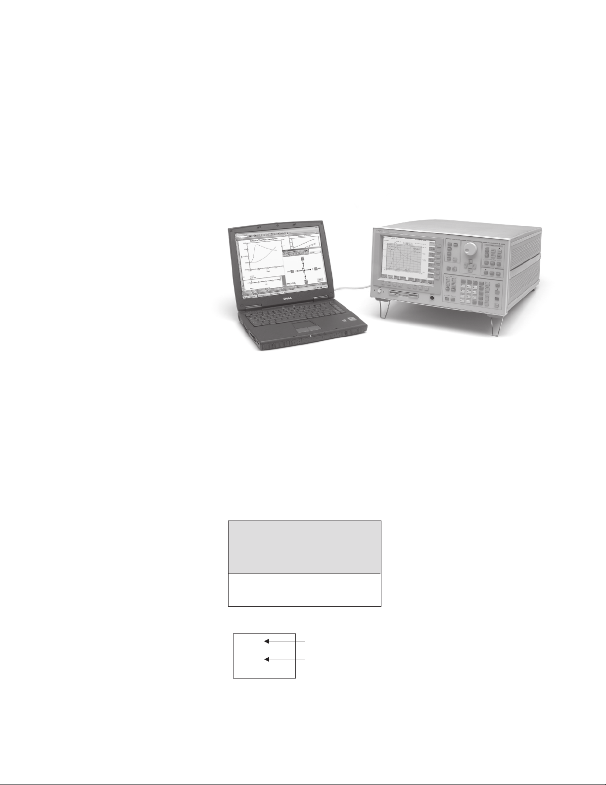
Introduction
Agilent 4155C and 4156C
Basic Functions
• Set measurement and/or stress
conditions
• Control measurement and/or stress
execution
• Perform arithmetic calculations
• Display measured and calculated
results on the LCD display
• Perform graphical analysis
• Store and recall measurement
setups, and measurement and
graphical display data
• Dump to printers or plotters for
hardcopy output
• Perform measurement and analysis
with built-in instrument BASIC
• Self test, Auto calibration
Configuration
The 4155C and 4156C both come
standard with I/CV 2.1 Lite
automation software. A PC-based
instrument controller with I/CV Lite
preinstalled and an Agilent 82357A
USB/GPIB interface are also included
with the standard configuration. You
have the option of deleting the
controller and cable from your order,
but I/CV Lite is always included with
both instruments. If you want the full
version of I/CV 2.1, you can request
the E5240BU upgrade kit when you
order a 4155C or 4156C. For more
information about the differences
between I/CV 2.1 Lite and I/CV 2.1,
please refer to the Agilent I/CV 2.1
Technical Overview, publication
number 5988-8474EN.
4155C
4xMPSMU
2xVMU 2xVMU
2xVSU 2xVSU
I/CV 2.1 Lite I/CV 2.1 Lite
Standard PC-based controller
and USB/GPIB interface
41501B (Optional)
GNDU
4156C
4xHRSMU
2xPGU (Option)
HPSMU (Option) or
2xMPSMU (Option)
1
SMU: Source Monitor Unit
Display resolution: 6 digits at each
current range (0.01fA display resolu tion at 10pA range)
HRSMU: High Resolution SMU
(1fA/2µV to 100mA/100V)
MPSMU: Medium Power SMU
(10fA/2µV to 100mA/100V)
HPSMU: High Power SMU
(10fA/2µV to 1A/200V)
VMU: Voltage Monitor Unit
(0.2µV resolution in differential
mode)
VSU: Voltage Source Unit
PGU: Pulse Generator Unit (1 channel)
GNDU: Ground Unit
1
Minimum number of installable MPSMU or
PGU is two.
2
Accuracy not guaranteed. Minimum
guaranteedresolution is 1fA at 10pA range.
1
2
S1
Page 2

Hardware
Specification Condition
The “supplemental” information and
“typical” entries in the following specifications are not warranted, but provide
useful information about the functions
and performance of the instruments.
The measurement and output accuracy
are specified at the rear panel connector terminals when referenced to the
Zero Check terminal under the following con-ditions:
1. 23° C ±5° C (double between 5° C to
18° C, and 28° C to 40° C if not noted
otherwise)
3. Ambient temperature change less
than ±1° C after auto calibration
execution.
4. Integration time: medium or long
5. Filter: ON (for SMUs)
6. Kelvin connection (for HRSMU,
HPSMU, and GNDU)
7. Calibration period: 1 year
2. After 40 minutes warm-up
Agilent 4156C Precision Semiconductor Parameter Analyzer
HRSMU (High Resolution SMU) Specifications
Voltage Range, Resolution, and Accuracy (HRSMU)
Voltage Set. Set. Meas. Meas. Max.
Range Reso. Accuracy Reso. Accuracy Current
±2V 100µV ±(0.02%+400µV) 2µV ±(0.01%+200µV) 100mA
±20V 1mV ±(0.02%+3mV) 20µV ±(0.01%+1mV) 100mA
±40V 2mV ±(0.025%+6mV) 40µV ±(0.015%+2mV)
±100V 5mV ±(0.03%+15mV) 100µV ±(0.02%+5mV)
1
100mA (Vout £20V), 50mA (20V<Vout£40V)
2
100mA (Vout £20V), 50mA (20V<Vout£40V), 20mA (40V<Vout£100V)
Current Range, Resolution, and Accuracy (HRSMU)
Current Set. Set. Meas. Meas. Max.
Range Reso. Accuracy Reso. Accuracy V
±10pA 10fA ±(4%+400fA)
±100pA 10fA ±(4%+400fA)
±1nA 100fA ±(0.5%+0.7pA+1fA×Vout)
±10nA 1pA ±(0.5%+4pA+10fA×Vout) 10fA ±(0.5%+2pA+10fA×Vout) 100V
±100nA 10pA ±(0.12%+40pA+100fA×Vout) 100fA ±(0.1%+20pA+100fA×Vout) 100V
±1µA 100pA ±(0.12%+400pA+1pA×Vout) 1pA ±(0.1%+200pA+1pA×Vout) 100V
±10µA 1nA ±(0.07%+4nA+10pA×Vout) 10pA ±(0.05%+2nA+10pA×Vout) 100V
±100µA 10nA ±(0.07%+40nA+100pA×Vout) 100pA ±(0.05%+20nA+100pA×Vout) 100V
±1mA 100nA ±(0.06%+400nA+1nA×Vout) 1nA ±(0.04%+200nA+1nA×Vout) 100V
±10mA 1µA ±(0.06%+4µA+10nA×Vout) 10nA ±(0.04%+2µA+10nA×Vout) 100V
±100mA 10µA ±(0.12%+40µA+100nA×Vout) 100nA ±(0.1%+20µA+100nA×Vout)
1
The accur acy is applicable when offset cancellation has been performed.
2
The offset current specification is multiplied by one of the following
factors depending upon the ambient temperature and humidity
(RH = Relative Humidity):
Temperature 5 - 60 60 - 80
5° C to 18° C ×2 ×2
18° C to 28° C ×1 ×2
28° C to 40° C ×2 ×5
3
100V (Iout£20mA) 40V (20mA<Iout£50mA) 20V (50mA<Iout£100mA)
Vout is the output voltage in volts. Iout is the output current in amps.
For example, accuracy specifications are given as ±% of set/measured
value (0.04%) plus offset value (200nA+1nA×Vout) for the 1mA range.
The offset value consists of a fixed part determined by the set/measure ment range and a proportional part that is multiplied by Vout or Vout/100.
Humidity % RH
1, 2
1, 2
1fA ±(4%+20fA+1fA×Vout/100)
1fA ±(4%+40fA+10fA×Vout/100)
2
10fA ±(0.5%+0.4pA+1fA×Vout)
1
2
1, 2
100V
1, 2
100V
2
100V
100
-
Output terminal/connection:
Dual triaxial connectors, Kelvin
(remote sensing)
Voltage/Current Compliance
(Limiting):
The SMU can limit output voltage or
current to prevent damaging the device
under test.
Voltage: 0 V to ±100 V
Current: ±100 fA to ±100 mA
Compliance Accuracy: Same as the
current (voltage) settling accuracy.
HRSMU Supplemental Information:
Maximum allowable cable resistance
when using Kelvin connection (Force,
Sense): 10
Typical voltage source output
resistance (Force line/non-Kelvin
connection): 0.2
Voltage measurement input resist ance/
current source output resistance:
15
³10
W (10 pA range)
Current compliance setting accuracy for
opposite polarity:
3
10 pA to 10 nA range: V/I setting
accuracy ±12% of range
100 nA to 100 mA range: V/I setting
accuracy ±2.5% of range
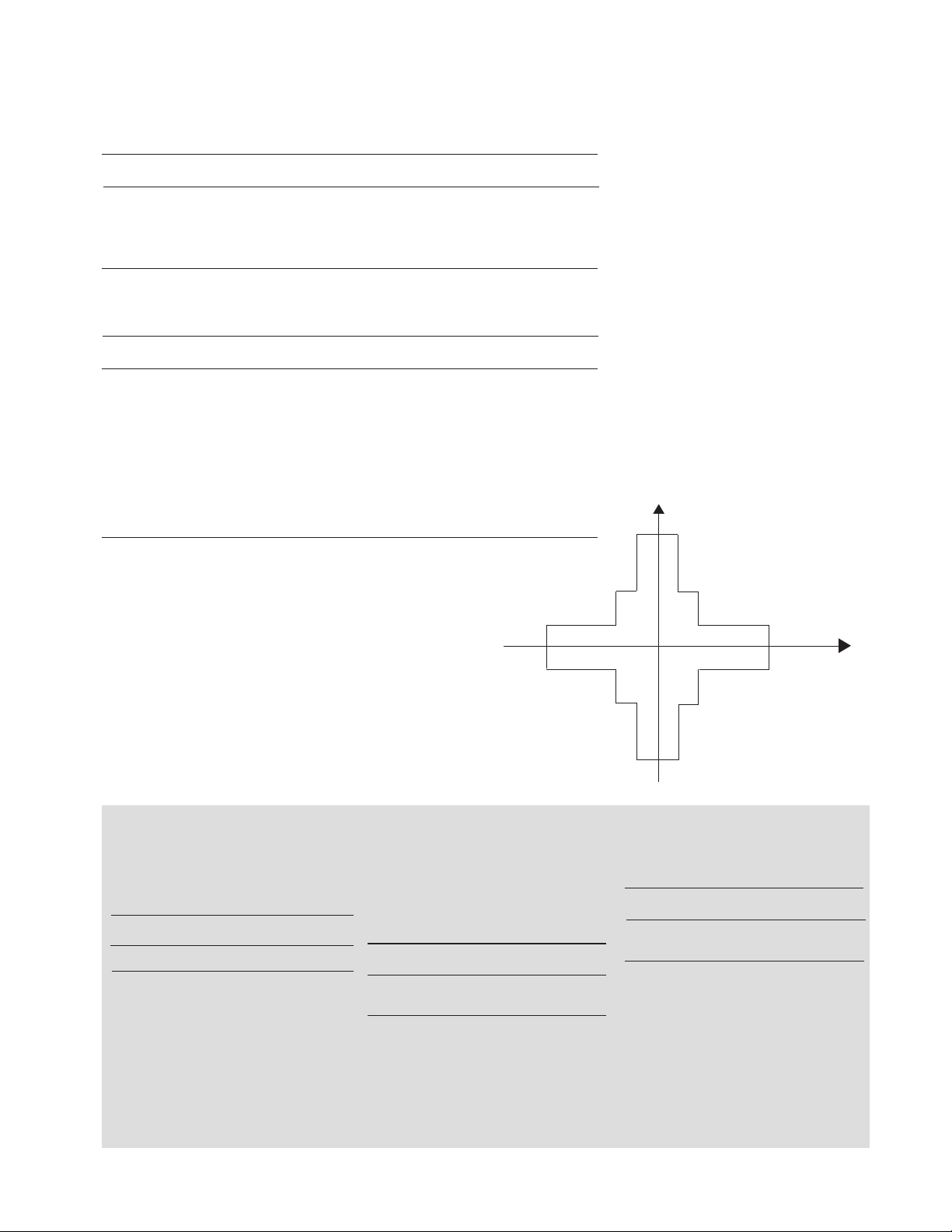
Current (mA)
100
50
20
20 40 100
20
-40-
20
-
W
W
HRSMU Measurement
and Output Range
Voltage (V)
50
-
100
-
2
Page 3
Agilent 4155C Semiconductor Parameter Analyzer
MPSMU (Medium Power SMU) Specifications
Voltage Range, Resolution, and Accuracy (MPSMU)
Voltage Set. Set. Meas. Meas. Max.
Range Reso. Accuracy Reso. Accuracy Current
±2V 100µV ±(0.03%+900µV+0.3×Iout) 2µV ±(0.02%+700µV+0.3×Iout) 100mA
±20V 1mV ±(0.03%+4mV+0.3×Iout) 20µV ±(0.02%+2mV+0.3×Iout) 100mA
±40V 2mV ±(0.03%+7mV+0.3×Iout) 40µV ±(0.02%+3mV+0.3×Iout)
±100V 5mV ±(0.04%+15mV+0.3×Iout) 100µV ±(0.03%+5mV+0.3×Iout)
1
100mA (Vout £20V), 50mA (20V<Vout £40V)
2
100mA (Vout £20V), 50mA (20V<Vout £40V), 20mA (40V<Vout£100V)
Current Range, Resolution, and Accuracy (MPSMU)
Current Set. Set. Meas. Meas. Max.
Range Reso. Accuracy Reso. Accuracy V
±1nA 100fA ±(0.5%+3pA+2fA×Vout) 10fA ±(0.5%+3pA+2fA×Vout) 100V
±10nA 1pA ±(0.5%+7pA+20fA×Vout) 10fA ±(0.5%+5pA+20fA×Vout) 100V
±100nA 10pA ±(0.12%+50pA+200fA×Vout) 100fA ±(0.1%+30pA+200fA×Vout) 100V
±1µA 100pA ±(0.12%+400pA+2pA×Vout) 1pA ±(0.1%+200pA+2pA×Vout) 100V
±10µA 1nA ±(0.12%+5nA+20pA×Vout) 10pA ±(0.1%+3nA+20pA×Vout) 100V
±100µA 10nA ±(0.12%+40nA+200pA×Vout) 100pA ±(0.1%+20nA+200pA×Vout 100V
±1mA 100nA ±(0.12%+500nA+2nA×Vout) 1nA ±(0.1%+300nA+2nA×Vout) 100V
±10mA 1µA ±(0.12%+4µA+20nA×Vout) 10nA ±(0.1%+2µA+20nA×Vout) 100V
±100mA 10µA ±(0.12%+50µA+200nA×Vout) 100nA ±(0.1%+30µA+200nA×Vout)
1
100V (Iout £20V), 40V (20mA<Iout£50mA), 20V (50mA<Iout£100mA)
Vout is the output voltage in volts. Iout is the output current in amps.
For example, accuracy specifications are given as ±% of set/measured
value (0.1%) plus offset value (30pA+200fA×Vout) for the 100nA range.
The offset value consists of a fixed part determined by the set/
measurement range and a proportional part that is multiplied by Vout.
1
2
1
Output terminal/connection:
Single triaxial connector, non-Kelvin
(no remote sensing)
Voltage/Current Compliance (Limiting):
The SMU can limit output voltage or
current to prevent damaging the device
under test.
Voltage: 0 V to ±100 V
Current: ±1 pA to ±100 mA
Compliance Accuracy: Same as the
current (voltage) settling accuracy.
MPSMU Supplemental Information:
Typical voltage source output
resistance: 0.3
W
Voltage measurement input resistance/
current source output resistance:
13
³10
W (1 nA range)
Current compliance setting accuracy
foropposite polarity:
1nA to 10 nA range: V/I setting
accuracy ±12% of range
100 nA to 100 mA range: V/I setting
accuracy ±2.5% of range
Current (mA)
100
MPSMU Measurement
and Output Range
50
20
VSU and VMU specifications are common to both the 4155C and 4156C
VSU (Voltage Source Unit)
Specifications
VSU Output Range:
Voltage Meas. Meas.
Range Reso. Accuracy
±20V 1mV ± (0.05% of setting +10mV)
1
Specification is applicable under no load
current. Max. Output Current: 100mA
VSU Supplemental Information:
Output resistance: 0.2 W (typical)
Maximum load capacitance: 10 µF
Maximum slew rate: 0.2 V/µs
Current limit: 120 mA (typical)
Output Noise: 1 mV rms (typical)
100
-
VMU (Voltage Monitor Unit)
Specifications
VMU Differential Mode Range,
Resolution, and Accuracy:
1
Diff V Meas. Meas.
Range Reso. Accuracy
±0.2V 0.2µV ±(0.03%+10µV+0.3µV×Vi)
±2V 2µV ±(0.02%+100µV+3µV×Vi)
Max. Common Mode Voltage: ± 20V
Note: Vi is the input voltage of VMU2 in volts.
For example, accuracy specifications are
given as ±% of set/measured value (0.02%)
plus offset value (100µV+3µV×Vi) for the 2V
range. The differential mode offset value
consists of a fixed part determined by the
measurement range and a proportional part
that is multiplied by Vi.
20
-40-
20 40 100
20
-
50
-
100
-
VMU Measurement Range, Resolution,
and Accuracy:
Voltage Meas. Meas.
Range Reso. Accuracy
±2V 2µV ±(0.02%+200µV)
±20V 20µV ± (0.02%+1mV)
VMU Supplemental Information:
Input Impedance: ³1G W
Input leakage current (@0 V): £500 pA
Measurement noise: 0.01% of range
(p-p) (typical) when integration time
is 10 PLC
Differential mode measurement noise:
0.005% of range (p-p) (typical) when
integration time is short.
Voltage (V)
3
Page 4

Agilent 41501B SMU and Pulse Generator Expander
HPSMU (High Power SMU) Specifications
Voltage Range, Resolution, and Accuracy (HPSMU)
Voltage Set. Set. Meas. Meas. Max.
Range Reso. Accuracy Reso. Accuracy Current
± 2V 100µV ±(0.03%+900µV) 2µV ±(0.02%+700µV) 1A
± 20V 1mV ±(0.03%+4mV) 20µV ±(0.02%+2mV) 1A
± 40V 2mV ±(0.03%+7mV) 40µV ±(0.02%+3mV) 500mA
±100V 5mV ±(0.04%+15mV) 100µV ±(0.03%+5mV) 125mA
±200V 10mV ±(0.045%+30mV) 200µV ±(0.035%+10mV) 50mA
Current Range, Resolution, and Accuracy (HPSMU)
Current Set. Set. Meas. Meas. Max.
Range Reso. Accuracy Reso. Accuracy V
±1nA 100fA ±(0.5%+3pA+2fA×Vout) 10fA ±(0.5%+3pA+2fA×Vout) 200V
±10nA 1pA ±(0.5%+7pA+20fA
±100nA 10pA ±(0.12%+50pA+200fA×Vout) 100fA ±(0.1%+30pA+200fA×Vout 200V
±1µA 100pA ±(0.12%+400pA+2pA
±10µA 1nA ±(0.12%+5nA+20pA×Vout) 10pA ±(0.1%+3nA+20pA×Vout) 200V
±100µA 10nA ±(0.12%+40nA+200pA
±1mA 100nA ±(0.12%+500nA+2nA×Vout) 1nA ±(0.1%+300nA+2nA×Vout) 200V
±10mA 1µA ±(0.12%+4µA+20nA
±100mA 10µA ±(0.12%+50µA+200nA×Vout) 100nA ±(0.1%+30µA+200nA×Vout) 1
±1A 100µA ±(0.5%+500µA+2µA×Vout) 1µA ±(0.5%+300µA+2µA×Vout) 2
1
200V (Iout £50mA), 100V (50mA<Iout£100mA)
2
200V (Iout £50mA), 100V (50mA<Iout£125mA), 40V (125mA<Iout£500mA), 20V (500mA<Iout£1mA)
Vout is the output voltage in volts. Iout is the output current in amps. For example, accuracy
specifications are given as ±% of set/measured value (0.1%) plus offset value (30pA+200fA
for the 100nA range. The offset value consists of a fixed part determined by the set/measurement
range and a proportional part that is multiplied by Vout.
×Vout) 10fA ±(0.5%+5pA+20fA×Vout) 200V
×Vout) 1pA ±(0.1%+200pA+2pA×Vout) 200V
×Vout) 100pA ±(0.1%+20nA+200pA×Vout 200V
×Vout) 10nA ±(0.1%+2µA+20nA×Vout) 200V
×Vout)
Output terminal/connection:
Dual triaxial connectors, Kelvin
(remote sensing)
Voltage/Current Compliance
(Limiting):
Voltage: 0V to ±200V
Current: ±1pA to ±1A
Compliance Accuracy: Same as
the current (voltage) settling
accuracy.
HPSMU Supplemental
Information:
Maximum allowable cable
resistance when using Kelvin
connection:
Force: 0.7W (100mA to 1A)
Force: 10W (£100mA)
Sense: 10W
Typical voltage source output
resistance (Force line/non-Kelvin
connection): 0.2W
Voltage measurement input
resistance/current source output
resistance:
13
³10
W (1nA range)
Current compliance setting
accuracy foropposite polarity:
1nA to 10nA range: V/I setting
accuracy ±12% of range
100nA to 1A range: V/I setting
accuracy ±2.5% of range
HPSMU Measurement
and Output Range
-200
-100 -40 -20
1000
500
125
50
-50
-125
-500
-1000
Current (mA)
Voltage (V)
100 20 40
200
4
Page 5

PGU (Pulse Generator Unit)
Specifications
Modes: Pulse or constant
Amplitude: 0Vp-p to 40Vp-p
Window: -40.0V to +40.0V
Maximum current:
±100mA
±200mA (pulse width: £1ms, average
current 100mA)
Pulse width: 1.0µs to 9.99s
Minimum resolution: 100ns
Pulse period: 2.0µs to 10.0s
Minimum resolution: 100ns
Delay: 0s to 10s
Minimum resolution: 100ns
Transition time: 100ns to 10ms
Minimum resolution: 1ns
Output impedance: 50W or low
impedance (£1W)
Burst count range: 1 – 65535
Pulse parameter accuracy:
Period: ±(2% +2ns)
Width: ±(3% +2ns)
Delay: ±(2% +40ns)
Transition time: ±(5% +10ns)
Trigger output:
Level: TTL
Timing: Same timing and width as
PGU1 pulse output
PGU Supplemental Information:
Overshoot: £±5% of amplitude ±10mV
(50W output impedance to 50W load)
Pulse width jitter: 0.2% + 100ps
Pulse period jitter: 0.2% + 100ps
Maximum slew rate: 100V/µs (50W
output impedance to 50W load)
Noise: 0.2% of range (@ DC output)
MPSMU Specifications
Same as 4155C MPSMU.
Pulse/DC Output Voltage and Accuracy (PGU)
Set Voltage
Parameter Range Resolution Accuracy
Base ±20V 4mV ±(1% of Base +50mV +1% of Pulse)
±40V 8mV ±(1% of Base +50mV +1% of Pulse)
Pulse ±20V 4mV ±(3% of Base +50mV)
±40V 8mV ±(3% of Base +50mV)
Note: DC output is performed by the Base Parameter.
1
Accuracy is specified at leading edge - trailing edge = 1µs
1
Pulse Range and Pulse Parameter (PGU)
Range Period Width Delay Set resolution
1 2µs -100µs 1µs - 99.9µs 0 - 100µs 0.1µs
2 100µs - 1000µs 1µs - 999µs 0 - 1000µs 1µs
3 1ms - 10ms 0.01ms - 9.99ms 0 - 10ms 10µs
4 10ms - 100ms 0.1ms - 99.9ms 0 - 100ms 100µs
5 100ms - 1000ms 1ms - 999ms 0 - 1000ms 1ms
6 1s - 10s 0.01s - 9.99s 0 - 10s 10ms
Note: Pulse width is defined when leading time is equal to trailing time. PGU2 must be set in the
same range as PGU1.
GNDU (Ground Unit)
Specifications:
Output Voltage: 0V ±100µV
Maximum sink current: 1.6A
Output terminal/connection:
Single triaxial connector,
Kelvin (remote sensing)
GNDU Supplemental Information
Load Capacitance: £1µF
Cable resistance:
Force £1W
Sense £10W
HRSMU, MPSMU, HPSMU
Supplemental Information
Maximum capacitive load: 1000pF
Maximum guard capacitance: 900pF
Maximum shield capacitance: 5000pF
Maximum guard offset voltage: ±1mV
Noise characteristics (typical, Filter: ON):
Voltage source noise: 0.01% of V
range (rms)
Current source noise: 0.1% of I range
(rms)
Voltage monitor noise: 0.02% of V
range (p-p)
Current monitor noise: 0.2% of I
Output overshoot (typical, Filter: ON):
Voltage source: 0.03% of V range
Current source: 1% of I range
Range switching transient noise
(typical, Filter: ON):
Voltage ranging: 250mV
Current ranging: 10mV
Maximum slew rate: 0.2V/µs
Leading/Trailing Edge Times (PGU)
Range Set Resolution` Accuracy
100ns - 1000ns 1ns ±(5% + 10ns)
0.5µs - 10µs 10ns ±(5% + 10ns)
5.0µs - 100µs 100ns ±(5% + 10ns)
50µs - 1000µs 1µs ±(5% + 10ns)
0.5ms - 10ms 10µs ±(5% + 10ns)
Restrictions:
Pulse width < Pulse Period, Delay time < Pulse period, Leading time < Pulse width ´ 0.8
Trailing time < (Pulse period - Pulse width) ´ 0.8
Period, width, and delay of PGU1 and PGU2 must be in the same range. Leading time and trailing
timefor a PGU must be in the same range.
5
Page 6

Capacitance Calculation Accuracy (Supplemental Data)
Accuracy is derived from the current range, voltage range, capacitance measurement and leakage current measurement integration times, and the guard capacitance of cabling and step voltage. The information in the chart below is based on
the following conditions: Voltage Range ±20V; Voltage Step: 100mV; Guard
Capacitance : 100pF; Equivalent parallel resistance of DUT: 1 ´ 1015W. The ratio
of integration times for capacitance measurement and leakage current measurement is 1:1.
HRSMU
Current Integration Max. Meas. Accuracy
Range Time Value Resolution Reading % Offset
10pA/
100pA
1nA 0.5sec 4.5nF 40fF 0.85 280fF
10nA
0.5sec 100pF/1pF 5fF 4.2 70fF
1sec 2pF/20pF 10fF 4.3 90fF
2sec 76pF/760pF 20fF 4.3 130fF
0.1sec 700pF 10fF 0.84 160fF
2sec 18nF 200fF 0.93 740fF
0.1sec 7nF 10fF 0.84 200fF
0.5sec 45nF 40fF 0.85 440fF
2sec 180nF 200fF 0.93 1.4pF
10sec 940nF 1pF 1.3 6.2pF
MPSMU
Integration Max. Meas. Accuracy
Current Time Value Resolution Reading % Offset
0.1sec 700pF 10fF 0.91 170fF
1nA 0.5sec 4.5nF 40fF 0.94 340fF
2sec 18nF 200fF 1.0 1pF
0.1sec 7nF 10fF 0.91 180fF
10nA 0.5sec 45nF 40fF 0.94 480fF
2sec 180nF 200fF 1.0 1.6pF
10sec 940nF 1pF 1.6 7.6pF
Current complicance must be smaller than the current range. The capacitance of
the DUT and measurement path must be smaller than the maximum measurement
value.
Functions
Measurement Setup
Setting
Fill-in-the-blanks using front-panel or
•
full-size external keyboard
Load settings from floppy disk or via
•
the LAN port
Program using internal Instrument
•
BASIC or via GPIB
HELP Function
•
Library: Default measure setup, Vce-
•
Ic, Vds-Id, Vgs-Id, and Vf-If are predefined softkeys
User-defined measurement setup
•
library
Auto file load function on power-up
•
Measurement
The 4155C and 4156C can
perform dc or pulsed force/measure,
and stress force. For dc, voltage/
current sweep and sampling (time
domain) measurements are available.
6
Voltage/Current Sweep
Measurement Characteristics
Each SMU and VSU can sweep using
VAR1 (primary sweep), VAR2
(subordinate sweep), or VAR1
(synchronous sweep).
VAR1
Primary sweep controls the staircase
(dc or pulsed) voltage or current
sweep.
Maximum number of steps: 1001 for
one VAR1 sweep.
Sweep type: linear or logarithmic
Sweep direction: Single or double sweep
Hold time: Initial wait time or wait
time after VAR2 is set: 0 to 655.35s
with 10ms resolution
Delay time: Wait time from VAR1 step
to the start of the measurement: 0 to
65.535s with 100µs resolution
VAR2
Subordinate linear staircase or linear
pulsed sweep. After primary sweep is
completed, the VAR2 unit output is
incremented.
Maximum number of steps: 128
VAR1
Staircase or pulse sweep synchronized
with the VAR1 sweep. Sweep is made
with a user specified ratio and offset
value. VAR1 output is calculated as
VAR1 = a ´ VAR1 + b, where “a” is the
user specified ratio and “b” is the user
specified offset value.
CONSTANT
A source unit can be set as a constant
voltage or current source depending on
the unit.
PULSE
One of the SMUs can be set as a pulse
source.
Pulse width: 0.5ms to 100ms, 100µs
resolution.
Pulse period: 5ms to 1s (³pulse width +
4ms), 100µs resolution.
SMU pulse setting accuracy (supplemental information, at fixed range
measurement except multichannel
measurement):
Width: 0.5% + 50µs
Period: 0.5% + 100µs
Trigger output delay for pulsed
measurement: 0 - 32.7ms with 100µs
resolution (< pulse width).
Sampling (Time Domain)
Measurement Characteristics
Displays the time sampled voltage/
current data versus time.
Max. sampling points: 10,001 (linear)
Sampling mode: linear, log, and
thinned-out
Note: The thinned-out mode is similar to
reverse-log sampling. Sampling measurement
continues by thinning out older data until the
sampling completion condition is satisfied.
Sampling interval range and resolution:
Linear scale (auto mode):
60µs to 480µs range: 20µs resolution
480µs to 1s range: 80µs resolution
1s to 65.535s range: 2ms resolution
Linear scale (no limit mode), log
scale, and thinned-out modes:
560µs (720µs at thinned-out mode)
to 1s range: 80µs resolution
1s to 65.535s range: 2ms resolution
Note: The following conditions must be set when
initial interval is less than 2ms.
Number of measurement channels: 1
•
Measurement ranging: fixed range
•
Stop condition: disable
•
Hold time:
Initial wait time: 0.03s to 655.35s,
100µs resolution
Sampling measurement stop condition:
Page 7

A condition to stop the sampling can
be defined.
Sampling interval setting accuracy
(supplemental data):
0.5% + 10µs (sampling interval £480µs)
0.5% + 10µs (480µs £sampling
interval <2ms)
0.5% + 100µs (2ms £sampling interval)
C-V Measurement
Characteristics
Capacitance is a calculated value
derived from the following equation:
DQ
C =
DV
DQ is the change in charge when DV,
the step voltage, is applied by the SMU;
DQ is derived from the measurement
current (amps) and the integration time
(seconds).
Maximum Measurable Value
Maximum measurable value depends
on thecurrent range, integration time,
and step voltage (refer to the chart in
supplemental data).
Capacitance Calculation Accuracy
Accuracy is dependent on accuracy of
the current measurement and voltage
measurement and the stray capacitance
and leakage current of measurement
path, etc. (Refer to the chart in supplemental data).
Zero Offset
Cancels stray capacitance of the
fixtures and test leads.
Leakage Current Compensation
Cancels the inf luence of the leakage
current to the capacitance measurement.
Stress Force Characteristics
SMU, VSU, and PGU output can be
forced for the user specified period.
Stress time set range: 500µs to
31,536,000s (365 days)
Resolution:
100µs (500µs £stress time £10s)
10ms (10s <stress time £31,536,000s)
Burst pulse count: 1 - 65,535 (PGU only)
Trigger: The 4155C and 4156C output a
gate trigger while stress channels are
forcing stress.
Knob Sweep
In knob sweep mode, sweep range is
controlled instantaneously with the
front-panel rotary knob. Only the
Channel Definition page need be defined.
Standby Mode
SMUs in “Standby” remain programmed
to their specified output value even
as other units are reset for the next
measurement.
Other Characteristics
Measurement Control: Single, append,
repeat, and stop
Stress Control: Stress force and stop
SMU Setting Capabilities: Limited auto ranging, voltage/current compliance,
power compliance, automatic sweep
abort functions, self-test, and self calibration.
Arithmetic and Analysis
Functions
Arithmetic Functions
User Functions
Up to six USER FUNCTIONS can be
defined using arithmetic expressions.
Measured data and analyzed variables
from graphics analysis (marker, cursor,
and line data) can be used in the
computation. The results can be
displayed on the LCD.
Arithmetic Operators
+, -, *, /, ^, LGT (logarithm, base 10),
LOG (logarithm, base e), EXP
(exponent), DELTA, DIFF (differential),
INTEG (integration), MAVG (moving
average), SQRT, ABS (absolute value),
MAX, MIN, AVG (averaging), COND
(conditional evaluation).
Physical Constants
Keyboard constants are stored in
memory as follows:
q:Electron Charge, 1.602177 E-19 C
k:Boltzman’s Constant, 1.380658 E-23
e (e): Dielectric Constant of Vacuum,
8.854188 E-12
Engineering Units
The following unit symbols are also
available on the keyboard: f (10
-12
p (10
m (10
), n (10-9 ), u or m (10-6 ),
-3
), K (103 ), M (10
Analysis Capabilities
Overlay Graph Comparison
A graphics plot can be stored and later
recalled as an overlay plane. Four overlay planes can be stored. One plane can
be overlaid onto the current data.
Marker
Marker to min/max, interpolation,
direct marker, and marker slip
Cursor
Long and short, direct cursor.
Line
Two lines, normal mode, grad mode,
tangent mode, and regression mode.
Scaling
Auto scale and zoom.
Data Variable Display
Up to two user defined parameters can
be displayed on the graphics screen.
Read Out Function
The read out functions are built-in
functions for reading various values
related to the marker, cursor, or line.
6
), G (10
-15
),
9
)
Automatic Analysis Function
On a graphics plot, the markers and
lines can be automatically located using
the auto analysis setup. Parameters can
be automatically determined using
automatic analysis, user function, and
read out functions.
User Variable
Display the data on the LCD via GPIB
or instrument BASIC.
Output
Display
Display Modes
Graphics and list.
Graphics Display
X-Y or X-Y1/Y2 plot of source current/
voltage, measured current/voltage, time,
or calculated USER FUNCTION data.
List Display
Measurement data and calculated
USER FUNCTION data are listed in
conjunction with VAR1 step number or
time domain sampling step number. Up
to eight data sets can be displayed.
Display
8.4-inch diagonal color active matrix
LCD, 640 dot (H) ´ 480 dot (V). More
than 99.99% of the pixels on an LCD
are active.
Hard Copy Functions
Graphics Hard Copy
Measured data and all data appearing
on the LCD can be output via GPIB,
parallel printer port, or network
interface to supported HP plotters or
printers. PCL, HR PCL (high-resolution
PCL), and HP-GL formats are supported (selectable).
Text Hard Copy
Print out setup information or measured data list as ASCII text via GPIB,
parallel printer port, or network
interface to supported HP plotters or
printers. PCL, HR PCL, and HP GL
formats are supported (selectable).
Hard Copy File
Hard copy output can be stored to an
internal or external mass storage
device instead of sending it to a printer
or plotter. The data can be stored in
PCL, HR PCL, TIFF, HR TIFF (highresolution TIFF), or HP GL formats.
Hard Copy via Network Interface
The network interface has lpr client
capability.
High-Resolution (HR) Mode
This file mode is available for cases
where an extremely clean print-out or
plot is desired.
Note: High-resolution mode takes significantly
greater CPU time to generate, so its use is
recommended for final reports only.
7
Page 8

Data Storage
Mass storage device:
Built-in 3.5-inch floppy disk drive
Media: 3.5-inch 2HD or 2DD diskette
Format type: HP LIF and DOS
User area: 1.44Mbyte (2HD) or
720Kbyte (2DD)
File types:
Auto start program file, initial setup
file, measurement setup file, mea
surement setup/result file, stress
setup file, customize file, hard copy
data file, and Instrument BASIC
program and data file.
Format of data made by the HP BASIC
program:
Data made by the HP BASIC program
and data made by the Instrument
BASIC program are compatible.
Network mass storage device:
An NFS mountable mass storage device
File types:
Auto start program file, initial setup
file, measurement setup file, measure ment setup/result file, stresS setup
file, customize file, and hard copy
data file.
Maximum number of files allowed per
directory on network mass storage
device: 199
Data storage (supplemental data):
2HD DOS format:
Available bytes: 1457K (byte)
File size:
Measurement setup: 3843 (byte)
Stress setup: 601 (byte)
Measurement setup/result
(Typical data): 15387 (byte)
(VAR1: 101, VAR2: 5)
Customized system setup: 1661 (byte)
Hardcopy data: 30317 (byte)
(Monochrome PCL 75DPI file)
Hardcopy data: 38702 (byte)
(monochrome TIFF file)
Note: For LIF format, the total number of files is
limited to 199.
Repeating and Automating
Test
Instrument Control
Agilent 4155C and 4156C function
control:
Internal or external computer controls
the 4155C and 4156C functions via
the GPIB interface
Command sets:
SCPI command set
Agilent FLEX command set
Agilent 4145B command set
Program Memory:
Using the Agilent FLEX command set,
the user can store program code in
the 4155C or the 4156C. The maximum
number of subprograms is 255 (8 bit).
External instrument remote control:
Control external equipment via the
GPIB interface.
8
Instrument BASIC
Instrument BASIC is a subset of
HP BASIC.
Functions:
Arithmetic operation, binary opera
tion, string manipulation, logical
operation, array operation, program
flow control, event-initiated branch
ing, program editing and debugging
support, mass storage operation,
instrument control, real-time clock,
softkey operation, and graphics.
Agilent 4145B automatic sequence
program (ASP) typing aid:
4145B ASP-like syntax softkeys are
available in instrument BASIC. A
4145B ASP file cannot be read by
the 4155C or 4156C.
Remote control:
Instrument BASIC is remote
controllable from an external
computer via the GPIB interface.
Instrument BASIC memory area
(supplemental data):
Program (text) area: 16K (byte)
Variable/stack area: 500K (byte)
Common variable area: 600K (byte)
Note: The memory size for common variable is
decreased when hard copy or disk operation is
performed.
Trigger
Input:
External trigger input starts a sweep
or sampling measurement or can be
used as a trigger input for continuing
an Instrument BASIC program.
Input Level:
TTL level, negative or positive edge
trigger
Output:
External edge trigger outputs can
be generated by the start of a sweep
measurement, the start of each
sweep step in a staircase sweep, the
start of each pulse leading edge for
an SMU in pulse mode, and the
issuance of an an IBASIC trigger out
command execution. In addition, you
can set the trigger signal to be active
during the Stress Force State. If you
have a 41501A/B with PGU option,
you can output a synchronized
trigger output through the 41501A/B
trigger output.
Output Level:
TTL level, negative or positive logic
4145B Data Compatibility
and Syntax Commands
Setup and data file
Measurement setup and data from the
4145B can be loaded.
GPIB program
GPIB programs for the 4145B can be
used when the 4145B command set is
selected.
Note: There is a possibility that GPIB programs
for the 4145B will need to be modified.
Interfaces
GPIB interface:
SH1, AH1, T6, L4, SR1, RL1, PP0,
DC1, DT1, C1, C2, C3, C4, C11, E2
Parallel interface: Centronics
RJ45:
Ethernet IEEE 802.3 10BASE-T for a
10Mbps CSMA/CD local area network
External keyboard:
Compatible PC-style 101-key
keyboard (mini DIN connector)
Interlock and LED connector R-BOX
control connector
Trigger in/out
SMU/PGU selector control connector
(41501B)
Sample Application
Programs
Flash EEPROM test
TDDB
Constant I (Electromigration test)
V-Ramp test
J-Ramp test
SWEAT
GO/NO-GO test
HCI degradation test
Charging pump test
Sample VEE Program
Vth measurement using the 4155C or
4156C, the E5250A, and a wafer prober.
VXI plug&play Drivers
VXI plug&play drivers for the
4155C and 4156C
Supported VXI plug&play operating
systems:
Microsoft Windows 95, 98, NT, 2000
Professional, and XP Professional
Format
Tree-structured function panel.
Panel mode for hardware configuration and manual parameter setting.
Parameter mode for variable definition
and I/O configuration.
General Specifications
Temperature range
Operating:
+10°C to +40°C (if using floppy
disk drive)
+5°C to +40°C (if not using floppy
disk drive)
Storage: -22°C to +60°C
Humidity range
Operating:
20% to 80% RH, non-condensing and
wet bulb temperature £29°C (if using
floppy disk drive)
15% to 80% RH, non-condensing and
wet bulb temperature £29°C (if not
using floppy disk drive)
Storage: 5% to 90% RH , non-condensing
and wet bulb temperature £39°C
Page 9

Altitude
Operating: 0 to 2,000 m (6,561 ft)
Storage: 0 to 4,600 m (15,091 ft)
Power requirement
90V to 264V, 47 to 63 Hz
Maximum VA
4155C and 4156C: 450VA
41501B: 350 VA
Regulatory Compliance
EMC: EN 61326-1:+A1, AS/NZS 2064.1
Safety:
CSA C22.2 NO.1010.1 (1992),
IEC 61010-1:+A2/EN 61010-1:+A2
UL3111-1:1994
Certification:
CE, CSA, NRTL/C, C-Tick
Dimensions
4155C and 4156C: 235mm H ´
426mm W ´ 600mm D
41501B: 190mm H ´
426mm W ´ 600mm D
Weight (approx.)
4155C and 4156C: 21kg
41501B: 16kg (option 412,
HPSMU + 2 ´ PGU)
4155C and 4156C
Furnished Accessories
Triaxial cable, 4 ea. (4155C)
Kelvin triaxial cable, 4 ea. (4156C)
Coaxial cable, 4 ea.
Interlock cable, 1 ea.
Keyboard, 1 ea.
User manual, 1 set
Sample application program disk, 1 ea.
Sample VEE program disk, 1 ea.
VXIplug&play drivers disk for the
4155C and 4156C, 1 ea.
VXIplug&play drivers disk for the
E5250A, 1 ea.
LAN Interface Test Adapter, 1 ea.
Accessory
Specifications
Specification Condition
The “supplemental information” and
“typical”entries in the following specifications are not warranted, but provide
useful information about the functions
and performance of the instruments
(23°C ±5°, 50% RH).
16440A SMU/Pulse Generator
Selector
The 16440A switches either an SMU
or PGU to the associated output port.
You can expand to 4 channels by
adding an additional 16440A. The
channel 1 PGU port provides a “PGU
OPEN” function, which can disconnect
the PGU by opening a semiconductor
relay. The 16440A cannot work without
two pulse generator units of the
41501A/B (SMU and Pulse Generator
Expander).
Channel configurations:
Two channels (CH1, CH2)
CH1: INPUT ports: 2
(SMU and PGU, PGU port has
additional series semiconductor relay)
OUTPUT port: 1
CH2: INPUT ports: 2 (SMU and PGU)
OUTPUT port: 1
Voltage and Current Range
Input port Max. V Max. I
SMU 200V 1.0A
PGU 40V 0.2A (AC Peak)
Supplemental Information
(at 23°C ± 5°C, 50%RH)
SMU port leakage current:
< 100fA @100V
SMU port residual resistance (typical):
0.2W
SMU port stray capacitance (typical
@1MHz):
Force « Common: 0.3pF
Force « Guard: 15pF
Guard « Common: 130pF
PGU port residual resistance: 3.4W
PGU port OFF capacitance (typical): 5pF
PGU port OPEN capacitance (typical):
700pF (@ 1MHz, Vin - Vout = 0V)
PGU port signal transfer characteristics
Overshoot: < 5% of pulse amplitude
(@20ns leading and trailing time, 50W
pulse generator source impedance,
50pF and 1MW in parallel load).
General Specifications
Dimensions:
50mm H ´ 250mm W ´ 275mm D
Approximate weight: 1.1kg
16441A R-BOX
The 16441A R-BOX adds a selectable
series resistor to the SMU output. You
can select the resistor from the setup
page, and the voltage drop due to the
series resistor is automaticallycompensated for in the measurement result.
Measurement limitations with the
4155C and 4156C and R-BOX:
If you measure device characteristics
including negative resistance over
1MW with the 4155C/4156C and
R-BOX, there is a possibility that
they cannot be measured. There is a
possibility that the 4155C and 4156C
cannot perform measurements
because of DUT oscillations even with
the R-BOX. Whether oscillation occurs
or not depends upon the DUT and
measurement conditions.
Number of SMU channels that can add
a resistor: 2
Resistor values:
1MW, 100kW, 10kW, 0W (each
channel)
Resistance accuracy:
0.3% (at 23°C ±5°C, between input output terminal)
Maximum voltage: 200V
Maximum current: 1A (0W selected)
Kelvin connection: Kelvin connection
is effective only when 0W is selected.
Supplemental Information
(at 23°C ± 5°C, 50%RH)
Leakage current: <100fA @ 100V
General Specifications
Dimensions:
72mm H ´ 250mm W ´ 270mm D
Approximate weight: 1.6kg
16442A Test Fixture
Channel Information
SMU:
6 channels (1 triaxial connector
per channel)
3 channels (1 Kelvin triaxial connector
per channel)
VSU:
2 channels (1 BNC connector per
channel)
VMU:
2 channels (1 BNC connector per
channel)
PGU:
2 channels (1 BNC connector per
channel)
GNDU:
1 channel (1 triaxial connector)
INTLK: 6-pin connector
Supplemental Information
(at 23°C ± 5°C, 50% RH)
SMU channel:
Leakage current: 10pA max @200V
(Force or Sense « Common)
Stray capacitance: 15pF max
(Force or Sense « Common)
Stray capacitance: 3pF typical
(Force or Sense « Other SMU)
Residual resistance: 60mW typical
(Force, Sense)
Guard capacitance: 70pF max
(Force or Sense « Guard)
VSU channel residual resistance:
60mW typical
VMU channel residual resistance:
60mW typical
PGU channel characteristic impedance:
50mW typical
GNDU channel residual resistance:
40mW typical (Force, Sense)
General Specifications
Temperature range:
Operating: +5°C to +40°C
Storage: -40°C to +70°C
Humidity range;
Operating: 5% to 80% RH
(no condensation)
Storage: 5% to 90% RH at 65°C
(no condensation)
Dimensions:
140 mm H ´ 260 mm W ´ 260 mm D
Weight (approx.): 2.5kg
9
Page 10

Automation Software
I/CV 2.1 Lite
Overview
Agilent I/CV 2.1 Lite provides
automated test solutions for semiconductor characterization. It supports the Agilent 4155C and 4156C,
the Agilent E5270 Series, the
Agilent E5250A Low Leakage
Switch, the Keithley 707 Switching Matrix, the Agilent 4284A and
4294A LCR meters, and many popular semiautomatic wafer probers.
I/CV 2.1 Lite also provides wizardbased test development, test execution, and sequencing along with
data logging and post- analysis
tools on Microsoft® Windows.®
10
Software Functions
Interactive Measurements
I/CV 2.1 Lite includes Agilent ICS
as the default measurement tool.
ICS provides point-and-click
measurements, intuitive matrix
control, and graphical analysis
capabilities for semiconductor
parametric measurements.
Created setups can be used as
measurement algorithms in the
script editor.
Script Editor
The script editor provides a
wizard-based interface for building test scripts used in the execution of automated tests. It allows
access to libraries of built- in
software components that support functions for creating test
plans. Components include:
• Automated sub-die prober
movement
• Switch connection execution
• Test algorithm execution
• Pass/Fail determination and
processing
• Conditional branching: IF,
ELSE
• Looping: FOR, WHILE
• User variable creation
• User prompts
• Message displays
• Test script commenting
Wafer Prober Navigation
I/CV 2.1 Lite provides support
for popular semiautomatic probers as well as several automatic
probers. Probe plans can be
defined that include sub-die
movement for performing automated test of multiple modules
or individual devices across a
wafer. Interactive prober control
can also be implemented for
analytical applications.
Page 11

Test Execution
Test scripts can be executed for
either manual or automated
tests. Manual tests are used for
single devices or single modules
(which can include several
devices) on a manual prober.
Automated tests are used for
wafer tests combing semiautomatic
prober control with die or module
test scripts. Test wizards provide
step-by-step instructions for
entering runtime information,
selection of wafer navigation plans,
selection of test plans, and
starting a test.
Auto-Analysis and Test Reporting
Parametric quantities from test
data can be extracted and
standard reports and graphs can
be generated. Supported graphs
and reports include:
• Color wafer maps
• Histograms
• Parameter statistics
• Parametric values vs. die
location
• Tables of I-V or C-V curve data
Software Measurement
Tool Support
Test algorithms can be created
using the following tools:
• Agilent ICS
• Microsoft VBScript (resident
in the script editor)
Computer System Requirements
Operating System
Microsoft Windows 2000
Professional or XP Professional
with Service Pack 1
CPU
300 MHz Pentium II-class
(500 MHz Pentium III-class or
faster recommended)
Hard Disk
5 GB available space
(20 GB recommended)
Memory
128 MB for Windows 2000
Professional
(256 MB recommended)
256 MB for Windows XP
Professional
Disk Drive
CD-ROM
Software Security
Parallel or USB port required
to attach security key
Control I/F
Supported GPIB card (see
requirements below)
GPIB Card Support
Agilent
Card
82341C (ISA)
82357A
(USB/GPIB)
Agilent I/O Library L.02.01 required
National Instruments
Card
PCI-GPIB
GPIB-USB-A
Windows 2000 Windows XP Pro.
Professional (Service Pack 1)
X –
X X
Windows 2000 Windows XP Pro.
Professional (Service Pack 1)
X X
X X
Prober Support
Cascade Microtech
S 300 with Nucleus version 2.1
or 2.5
Summit 12k with Nucleus version
2.1 or 2.5
Electroglas
2001 and 408X
SUSS MicroTec
All SUSS MicroTec probe stations
using Prober Bench NT v4.2
Vector Semiconductor
AX-2000 / VX-3000, Version 3.2
or later
Supported Measurement
Instruments
• E5270 Series of Parametric
Measurement Solutions
• 4155A/B/C Semiconductor
Parameter Analyzer
• 4156A/B/C Precision Semicon ductor Parameter Analyzer
• 4284A Precision LCR Meter
• 4294A Impedance Analyzer*
• E5250A Low Leakage Switch
Mainframe
• Keithley 707 Switch
* VBScript libraries are supplied.
11
Page 12

For more information about Agilent and its
products, go to www.agilent.com.
For more information about Agilent Technologies
semiconductor test products, applications, and
services, visit our website: www.agilent.com/
go/semiconductor or you can call one of the
centers listed and ask to speak with a
semiconductor test sales representative.
Americas
Brazil (11) 4197-3600
Canada (French) 1 877 894-4414
Canada (English) 1 800 447-8378
Mexico 33 134-5841
United States 1 800 447-8378
Asia/Asia Pacific
Australia 1 800 629-485
China 1 800 276-3059
Hong Kong 852 2599 7889
India 91/11 690-6156
Japan 0120 421-345
Malaysia 1 800 880-780
New Zealand 0 800 738 378
Philippines 1 800 1651-0135
Singapore 1 800 276-3059
South Korea 080 778-0011
Taiwan 0 800 047-662
Thailand 1 800 2758-5822
Europe
Austria (01) 25 125-7183
Belgium (0) 2 404-9380
Denmark 080301040
Finland 20 547-9999
France (0) 825 010710
Germany (0) 18 05 24-63 34
Greece 20 547-9999
Ireland 016158393
Italy 02 92 60 8333
Luxembourg (0) 2 404-9340
Netherlands (0) 20 547-9999
Poland 20 547-9999
Russia 20 547-9999
Spain 91 631 3383
Sweden 020 120-9975
Switzerland (Italian) (0) 2 92 60 8484
Switzerland (German) (0) 1 735-9300
Switzerland (French) (0) 825 010 700
United Kingdom (0) 7004 222-222
Middle East
Israel 20 547-9999
Technical data subject to change without notice.
Microsoft and Windows are U.S. registered
trademarks of Microsoft Corporation.
© Copyright 2002 Agilent Technologies
Printed in USA April 21, 2003
5988-9238EN
S1
 Loading...