

Page 1

VXIplug&play Driver User’s Guide
HP 4155B/4156B Semiconductor Parameter Analyzer
04156-90710
July 1998
© Copyright 1997,1998 Hewlett-Packard Company
Page 2

Legal Notice
The information contained in this document is subject to change without notice.
Copyright © 1997,1998 Hewlett-Packard Company.
This document contains information which is protected by copyright. All rights are
reserved. Reproduction, adaptation, or translation with out prior written permission
is prohibited, except as allowed under the copyright laws.
• Product Warranty
Hewlett-Packard warrants Hewlett-Packard hardware, accessories and supplies
against defects in materials and workmanship for the p eriod of one year fro m the
warranty start date specified below. If Hewlett-Packard receives notice of such
defects during the warranty period, Hewlett-Packard will, at its option, either
repair or replace products which prove to be defective. Replacement products
may be either new or like-new.
For warranty service or repair, this product must be returned to a service facility
designed by Hewlett-Packard. Buyer shall prepay shipping charges to
Hewlett-Packard and Hewlett-Packard shall pay shipping charges to return the
product to Buyer. However, Buyer shall pay all shipping charges, duties, and
taxes for products returned to Hewlett-Packard from another country.
Hewlett-Packard warrants that Hewlett-Packard software will not fail to execute
its programming instructions, for the period of one year from the warranty start
date specified below , due to defects in material and workmanship when properly
installed and used. If Hewlett-Packard receives notice of such defects during the
warranty period, Hewlett-Packard will replace software media which does not
execute its programming instructions due to such defects.
Hewlett-Packard does not warrant that the operation of Hewlett-Packard
products will be uninterrupted or error free. If Hewlett-Packard is unable, within
a reasonable time, to repair or replace any product to a condition as warranted,
customer will be entitled to a refund of the purchase price upon prompt return of
the product.
The Hewlett-Packard products may contain remanufactured parts equivalent to
new in performance or may have been subject to incidental use.
2
Page 3

The warranty period begins on the date of delivery or on the date of installation
if installed by Hewlett-Packard. If customer schedules or delays
Hewlett-Packard installation more than 30 days after delivery, warranty begins
on the 31st day from delivery.
Warranty does not apply to defects resulting from (a) improper or inadequate
maintenance or calibration, (b) software, interfacing, parts or supp lies not
supplied by Hewlett-Packard, (c) unauthorized modification or misuse, (d)
operation outside of the published environmental specifications for the product,
or (e) improper site preparation or maintenance.
To the extent allowed by local law, the above warranties are exclusive and no
other warranty or condition, whether written or oral, is expressed or implied and
Hewlett-Packard specifically disclaims any implied warranties or conditions of
merchantability, satisfactory quality, and fitness for a particular purpose.
Hewlett-Packard will be liable for damage to tangible property per incident up to
the greater of $300,000 or the actual amount paid for the product that is the
subject of the claim, and for damages for bodily injury or death, to the extent
that all such damages are determined by a court of competent jurisdiction to
have been directly caused by a defective Hewlett-Packard product.
To the extent allowed by local law, the remedies in this warranty statement are
customer’s sole and exclusive remedies. Expect as indicated above, in no event
will Hewlett-Packard or its suppliers be liable for loss of date or for di rect,
special, incidental, consequential (incl uding lost profit or date), or other damage,
whether based in contract, tort, or otherwise.
For consumer transactions in Australia and New Zealand: the warranty terms
contained in this statement, except to the extent lawfully perm itted, do not
exclude, restrict or modify and are in addition to the mandatory statutory rights
applicable to the sale of this product to you.
• Assistance
Product maintenance agreements and other customer assistance agreements are
available for Hewlett-Packard products.
For any assistance, contact your nearest Hewlett-Packard Sales Office.
• Certification
Hewlett-Packard Company certifies that this prod uct met its published
specifications at the time of shipment from the factory. HP further certifies that
its calibration measurements are traceable to the National Institute of Standards
3
Page 4

and Technology (NIST), to the extent allowed by the Institute’s calibration
facility, and to the calibration facilities of other International Standards
Organization members.
Microsoft, Windows, Windows NT, Visial Basic, and Visual C/C++ are registered
trademarks of M i crosoft Corpor ation.
Borland C/C++ Builder is registered trademark of International, Inc.
LabWindows and LabVIEW are registered trademarks of National Instruments
Corporation.
Prober Control Software (PCS) is a product of Cascade Michrotech, Inc.
4
Page 5

Contents
1. Installation
Software Requirements . . . . . . . . . . . . . . . . . . . . . . . . . . . . . . . . . . . . . . . . . . . . . .17
Hardware Requirements with HP VEE . . . . . . . . . . . . . . . . . . . . . . . . . . . . . . . . . .18
Installing the HP 4155B/4156B Driver . . . . . . . . . . . . . . . . . . . . . . . . . . . . . . . . . .19
To Configure the Interface using HP I/O Library . . . . . . . . . . . . . . . . . . . . . . . .20
To Install the Driver . . . . . . . . . . . . . . . . . . . . . . . . . . . . . . . . . . . . . . . . . . . . . . .21
2. Driver Functions
Driver Functions for HP 4155B/4156B. . . . . . . . . . . . . . . . . . . . . . . . . . . . . . . . . .25
hp4156b_abortMeasure . . . . . . . . . . . . . . . . . . . . . . . . . . . . . . . . . . . . . . . . . . . .28
hp4156b_addSampleSyncIv. . . . . . . . . . . . . . . . . . . . . . . . . . . . . . . . . . . . . . . . .28
hp4156b_addSampleSyncPulse . . . . . . . . . . . . . . . . . . . . . . . . . . . . . . . . . . . . . .29
hp4156b_addStressSyncIv . . . . . . . . . . . . . . . . . . . . . . . . . . . . . . . . . . . . . . . . . .30
hp4156b_addStressSyncPulse . . . . . . . . . . . . . . . . . . . . . . . . . . . . . . . . . . . . . . .31
hp4156b_autoCal . . . . . . . . . . . . . . . . . . . . . . . . . . . . . . . . . . . . . . . . . . . . . . . . .31
hp4156b_clearSampleSync . . . . . . . . . . . . . . . . . . . . . . . . . . . . . . . . . . . . . . . . .32
hp4156b_clearStressSync. . . . . . . . . . . . . . . . . . . . . . . . . . . . . . . . . . . . . . . . . . .32
hp4156b_close . . . . . . . . . . . . . . . . . . . . . . . . . . . . . . . . . . . . . . . . . . . . . . . . . . .32
hp4156b_cmd. . . . . . . . . . . . . . . . . . . . . . . . . . . . . . . . . . . . . . . . . . . . . . . . . . . .32
hp4156b_cmdData_Q. . . . . . . . . . . . . . . . . . . . . . . . . . . . . . . . . . . . . . . . . . . . . .33
hp4156b_cmdInt. . . . . . . . . . . . . . . . . . . . . . . . . . . . . . . . . . . . . . . . . . . . . . . . . .33
hp4156b_cmdInt16Arr_Q . . . . . . . . . . . . . . . . . . . . . . . . . . . . . . . . . . . . . . . . . .34
hp4156b_cmdInt16_Q . . . . . . . . . . . . . . . . . . . . . . . . . . . . . . . . . . . . . . . . . . . . .34
hp4156b_cmdInt32Arr_Q . . . . . . . . . . . . . . . . . . . . . . . . . . . . . . . . . . . . . . . . . .35
hp4156b_cmdInt32_Q . . . . . . . . . . . . . . . . . . . . . . . . . . . . . . . . . . . . . . . . . . . . .35
hp4156b_cmdReal . . . . . . . . . . . . . . . . . . . . . . . . . . . . . . . . . . . . . . . . . . . . . . . .36
hp4156b_cmdReal64Arr_Q. . . . . . . . . . . . . . . . . . . . . . . . . . . . . . . . . . . . . . . . .36
hp4156b_cmdReal64_Q. . . . . . . . . . . . . . . . . . . . . . . . . . . . . . . . . . . . . . . . . . . .37
hp4156b_cmdString_Q. . . . . . . . . . . . . . . . . . . . . . . . . . . . . . . . . . . . . . . . . . . . .37
hp4156b_dcl. . . . . . . . . . . . . . . . . . . . . . . . . . . . . . . . . . . . . . . . . . . . . . . . . . . . .37
5
Page 6

Contents
hp4156b_error_message . . . . . . . . . . . . . . . . . . . . . . . . . . . . . . . . . . . . . . . . . . .38
hp4156b_error_query. . . . . . . . . . . . . . . . . . . . . . . . . . . . . . . . . . . . . . . . . . . . . .38
hp4156b_errorQueryDetect . . . . . . . . . . . . . . . . . . . . . . . . . . . . . . . . . . . . . . . . .39
hp4156b_errorQueryDetect_Q. . . . . . . . . . . . . . . . . . . . . . . . . . . . . . . . . . . . . . .39
hp4156b_esr_Q . . . . . . . . . . . . . . . . . . . . . . . . . . . . . . . . . . . . . . . . . . . . . . . . . .40
hp4156b_execCal. . . . . . . . . . . . . . . . . . . . . . . . . . . . . . . . . . . . . . . . . . . . . . . . .40
hp4156b_execOffsetCancel. . . . . . . . . . . . . . . . . . . . . . . . . . . . . . . . . . . . . . . . .41
hp4156b_force . . . . . . . . . . . . . . . . . . . . . . . . . . . . . . . . . . . . . . . . . . . . . . . . . . .42
hp4156b_forcePulse. . . . . . . . . . . . . . . . . . . . . . . . . . . . . . . . . . . . . . . . . . . . . . .43
hp4156b_init . . . . . . . . . . . . . . . . . . . . . . . . . . . . . . . . . . . . . . . . . . . . . . . . . . . .44
hp4156b_measureM. . . . . . . . . . . . . . . . . . . . . . . . . . . . . . . . . . . . . . . . . . . . . . .45
hp4156b_measureP . . . . . . . . . . . . . . . . . . . . . . . . . . . . . . . . . . . . . . . . . . . . . . .46
hp4156b_offsetCancel . . . . . . . . . . . . . . . . . . . . . . . . . . . . . . . . . . . . . . . . . . . . .46
hp4156b_opc_Q. . . . . . . . . . . . . . . . . . . . . . . . . . . . . . . . . . . . . . . . . . . . . . . . . .47
hp4156b_readData. . . . . . . . . . . . . . . . . . . . . . . . . . . . . . . . . . . . . . . . . . . . . . . .47
hp4156b_readStatusByte_Q. . . . . . . . . . . . . . . . . . . . . . . . . . . . . . . . . . . . . . . . .48
hp4156b_recoverOutput. . . . . . . . . . . . . . . . . . . . . . . . . . . . . . . . . . . . . . . . . . . .48
hp4156b_reset . . . . . . . . . . . . . . . . . . . . . . . . . . . . . . . . . . . . . . . . . . . . . . . . . . .48
hp4156b_revision_query . . . . . . . . . . . . . . . . . . . . . . . . . . . . . . . . . . . . . . . . . . .49
hp4156b_sample . . . . . . . . . . . . . . . . . . . . . . . . . . . . . . . . . . . . . . . . . . . . . . . . .50
hp4156b_self_test . . . . . . . . . . . . . . . . . . . . . . . . . . . . . . . . . . . . . . . . . . . . . . . .51
hp4156b_setFilter. . . . . . . . . . . . . . . . . . . . . . . . . . . . . . . . . . . . . . . . . . . . . . . . .52
hp4156b_setInteg. . . . . . . . . . . . . . . . . . . . . . . . . . . . . . . . . . . . . . . . . . . . . . . . .52
hp4156b_setIv . . . . . . . . . . . . . . . . . . . . . . . . . . . . . . . . . . . . . . . . . . . . . . . . . . .53
hp4156b_setPbias. . . . . . . . . . . . . . . . . . . . . . . . . . . . . . . . . . . . . . . . . . . . . . . . .54
hp4156b_setPguR . . . . . . . . . . . . . . . . . . . . . . . . . . . . . . . . . . . . . . . . . . . . . . . .55
hp4156b_setPiv . . . . . . . . . . . . . . . . . . . . . . . . . . . . . . . . . . . . . . . . . . . . . . . . . .56
hp4156b_setSample. . . . . . . . . . . . . . . . . . . . . . . . . . . . . . . . . . . . . . . . . . . . . . .57
hp4156b_setStress . . . . . . . . . . . . . . . . . . . . . . . . . . . . . . . . . . . . . . . . . . . . . . . .57
hp4156b_setSweepSync. . . . . . . . . . . . . . . . . . . . . . . . . . . . . . . . . . . . . . . . . . . .58
hp4156b_setSwitch . . . . . . . . . . . . . . . . . . . . . . . . . . . . . . . . . . . . . . . . . . . . . . .59
hp4156b_setVm. . . . . . . . . . . . . . . . . . . . . . . . . . . . . . . . . . . . . . . . . . . . . . . . . .59
6
Page 7

Contents
hp4156b_spotMeas. . . . . . . . . . . . . . . . . . . . . . . . . . . . . . . . . . . . . . . . . . . . . . . .60
hp4156b_startMeasure . . . . . . . . . . . . . . . . . . . . . . . . . . . . . . . . . . . . . . . . . . . . .61
hp4156b_stopMode . . . . . . . . . . . . . . . . . . . . . . . . . . . . . . . . . . . . . . . . . . . . . . .62
hp4156b_stress. . . . . . . . . . . . . . . . . . . . . . . . . . . . . . . . . . . . . . . . . . . . . . . . . . . 63
hp4156b_sweepIv. . . . . . . . . . . . . . . . . . . . . . . . . . . . . . . . . . . . . . . . . . . . . . . . .64
hp4156b_sweepMiv . . . . . . . . . . . . . . . . . . . . . . . . . . . . . . . . . . . . . . . . . . . . . . .65
hp4156b_sweepPbias . . . . . . . . . . . . . . . . . . . . . . . . . . . . . . . . . . . . . . . . . . . . . .67
hp4156b_sweepPiv. . . . . . . . . . . . . . . . . . . . . . . . . . . . . . . . . . . . . . . . . . . . . . . .68
hp4156b_timeOut. . . . . . . . . . . . . . . . . . . . . . . . . . . . . . . . . . . . . . . . . . . . . . . . .69
hp4156b_timeOut_Q . . . . . . . . . . . . . . . . . . . . . . . . . . . . . . . . . . . . . . . . . . . . . .69
hp4156b_zeroOutput . . . . . . . . . . . . . . . . . . . . . . . . . . . . . . . . . . . . . . . . . . . . . .69
Driver Functions for HP E5250A . . . . . . . . . . . . . . . . . . . . . . . . . . . . . . . . . . . . . .70
hpe5250a_biasChanCard . . . . . . . . . . . . . . . . . . . . . . . . . . . . . . . . . . . . . . . . . . .72
hpe5250a_biasChanList . . . . . . . . . . . . . . . . . . . . . . . . . . . . . . . . . . . . . . . . . . . . 72
hpe5250a_biasChanList_Q. . . . . . . . . . . . . . . . . . . . . . . . . . . . . . . . . . . . . . . . . .73
hpe5250a_biasPort . . . . . . . . . . . . . . . . . . . . . . . . . . . . . . . . . . . . . . . . . . . . . . . .74
hpe5250a_biasState . . . . . . . . . . . . . . . . . . . . . . . . . . . . . . . . . . . . . . . . . . . . . . . 74
hpe5250a_close . . . . . . . . . . . . . . . . . . . . . . . . . . . . . . . . . . . . . . . . . . . . . . . . . .75
hpe5250a_closeCard_Q . . . . . . . . . . . . . . . . . . . . . . . . . . . . . . . . . . . . . . . . . . . .75
hpe5250a_closeList . . . . . . . . . . . . . . . . . . . . . . . . . . . . . . . . . . . . . . . . . . . . . . .76
hpe5250a_closeList_Q. . . . . . . . . . . . . . . . . . . . . . . . . . . . . . . . . . . . . . . . . . . . .77
hpe5250a_cmd . . . . . . . . . . . . . . . . . . . . . . . . . . . . . . . . . . . . . . . . . . . . . . . . . . .77
hpe5250a_cmdData_Q. . . . . . . . . . . . . . . . . . . . . . . . . . . . . . . . . . . . . . . . . . . . .78
hpe5250a_cmdInt. . . . . . . . . . . . . . . . . . . . . . . . . . . . . . . . . . . . . . . . . . . . . . . . .78
hpe5250a_cmdInt16Arr_Q. . . . . . . . . . . . . . . . . . . . . . . . . . . . . . . . . . . . . . . . . .79
hpe5250a_cmdInt16_Q . . . . . . . . . . . . . . . . . . . . . . . . . . . . . . . . . . . . . . . . . . . .79
hpe5250a_cmdInt32Arr_Q. . . . . . . . . . . . . . . . . . . . . . . . . . . . . . . . . . . . . . . . . .80
hpe5250a_cmdInt32_Q . . . . . . . . . . . . . . . . . . . . . . . . . . . . . . . . . . . . . . . . . . . .80
hpe5250a_cmdReal . . . . . . . . . . . . . . . . . . . . . . . . . . . . . . . . . . . . . . . . . . . . . . .81
hpe5250a_cmdReal64Arr_Q . . . . . . . . . . . . . . . . . . . . . . . . . . . . . . . . . . . . . . . .81
hpe5250a_cmdReal64_Q . . . . . . . . . . . . . . . . . . . . . . . . . . . . . . . . . . . . . . . . . . . 82
7
Page 8

Contents
hpe5250a_cmdString_Q. . . . . . . . . . . . . . . . . . . . . . . . . . . . . . . . . . . . . . . . . . . .82
hpe5250a_compenC. . . . . . . . . . . . . . . . . . . . . . . . . . . . . . . . . . . . . . . . . . . . . . .83
hpe5250a_connRuleSeq. . . . . . . . . . . . . . . . . . . . . . . . . . . . . . . . . . . . . . . . . . . .84
hpe5250a_couplePort. . . . . . . . . . . . . . . . . . . . . . . . . . . . . . . . . . . . . . . . . . . . . .85
hpe5250a_coupleState . . . . . . . . . . . . . . . . . . . . . . . . . . . . . . . . . . . . . . . . . . . . .86
hpe5250a_dcl. . . . . . . . . . . . . . . . . . . . . . . . . . . . . . . . . . . . . . . . . . . . . . . . . . . .86
hpe5250a_error_message. . . . . . . . . . . . . . . . . . . . . . . . . . . . . . . . . . . . . . . . . . .87
hpe5250a_error_query. . . . . . . . . . . . . . . . . . . . . . . . . . . . . . . . . . . . . . . . . . . . .87
hpe5250a_errorQueryDetect . . . . . . . . . . . . . . . . . . . . . . . . . . . . . . . . . . . . . . . .88
hpe5250a_errorQueryDetect_Q. . . . . . . . . . . . . . . . . . . . . . . . . . . . . . . . . . . . . .88
hpe5250a_esr_Q. . . . . . . . . . . . . . . . . . . . . . . . . . . . . . . . . . . . . . . . . . . . . . . . . .89
hpe5250a_func. . . . . . . . . . . . . . . . . . . . . . . . . . . . . . . . . . . . . . . . . . . . . . . . . . .89
hpe5250a_init. . . . . . . . . . . . . . . . . . . . . . . . . . . . . . . . . . . . . . . . . . . . . . . . . . . .90
hpe5250a_opc_Q . . . . . . . . . . . . . . . . . . . . . . . . . . . . . . . . . . . . . . . . . . . . . . . . .90
hpe5250a_openCard. . . . . . . . . . . . . . . . . . . . . . . . . . . . . . . . . . . . . . . . . . . . . . .91
hpe5250a_openList . . . . . . . . . . . . . . . . . . . . . . . . . . . . . . . . . . . . . . . . . . . . . . .91
hpe5250a_openList_Q. . . . . . . . . . . . . . . . . . . . . . . . . . . . . . . . . . . . . . . . . . . . .92
hpe5250a_readStatusByte_Q. . . . . . . . . . . . . . . . . . . . . . . . . . . . . . . . . . . . . . . .92
hpe5250a_reset. . . . . . . . . . . . . . . . . . . . . . . . . . . . . . . . . . . . . . . . . . . . . . . . . . .93
hpe5250a_revision_query . . . . . . . . . . . . . . . . . . . . . . . . . . . . . . . . . . . . . . . . . .93
hpe5250a_selectCompenFile. . . . . . . . . . . . . . . . . . . . . . . . . . . . . . . . . . . . . . . .94
hpe5250a_self_test. . . . . . . . . . . . . . . . . . . . . . . . . . . . . . . . . . . . . . . . . . . . . . . .95
hpe5250a_testClear . . . . . . . . . . . . . . . . . . . . . . . . . . . . . . . . . . . . . . . . . . . . . . .95
hpe5250a_testExec_Q . . . . . . . . . . . . . . . . . . . . . . . . . . . . . . . . . . . . . . . . . . . . .96
hpe5250a_timeOut. . . . . . . . . . . . . . . . . . . . . . . . . . . . . . . . . . . . . . . . . . . . . . . .96
hpe5250a_timeOut_Q . . . . . . . . . . . . . . . . . . . . . . . . . . . . . . . . . . . . . . . . . . . . .96
3. Programming Examples Using HP VEE
Programming Basics . . . . . . . . . . . . . . . . . . . . . . . . . . . . . . . . . . . . . . . . . . . . . . . .99
Registrating the Driver on HP VEE. . . . . . . . . . . . . . . . . . . . . . . . . . . . . . . . . .100
Basic Objects to Control the Instrument . . . . . . . . . . . . . . . . . . . . . . . . . . . . . .102
8
Page 9

Contents
To display the To/From object . . . . . . . . . . . . . . . . . . . . . . . . . . . . . . . . . . . .103
To define transactions in the To/From object . . . . . . . . . . . . . . . . . . . . . . . . .104
To set input parameters. . . . . . . . . . . . . . . . . . . . . . . . . . . . . . . . . . . . . . . . . .105
To use the Help function. . . . . . . . . . . . . . . . . . . . . . . . . . . . . . . . . . . . . . . . .106
To use input variables. . . . . . . . . . . . . . . . . . . . . . . . . . . . . . . . . . . . . . . . . . .107
To create output terminals in the To/From object. . . . . . . . . . . . . . . . . . . . . .108
To display/connect the Data object. . . . . . . . . . . . . . . . . . . . . . . . . . . . . . . . .109
To display/connect the Display object . . . . . . . . . . . . . . . . . . . . . . . . . . . . . .109
Debugging Your Program. . . . . . . . . . . . . . . . . . . . . . . . . . . . . . . . . . . . . . . . . .110
To recover control mode. . . . . . . . . . . . . . . . . . . . . . . . . . . . . . . . . . . . . . . . .110
To check for instrument error. . . . . . . . . . . . . . . . . . . . . . . . . . . . . . . . . . . . .111
Restrictions When Using the Driver with HP VEE . . . . . . . . . . . . . . . . . . . . . .112
Invalid functions in the VEE program . . . . . . . . . . . . . . . . . . . . . . . . . . . . . .112
Invalid use of the NULL pointer. . . . . . . . . . . . . . . . . . . . . . . . . . . . . . . . . . .112
High-Speed Spot Measurements . . . . . . . . . . . . . . . . . . . . . . . . . . . . . . . . . . . . . .113
Multi-Channel Spot Measurements . . . . . . . . . . . . . . . . . . . . . . . . . . . . . . . . . . . .115
Staircase Sweep Measurements. . . . . . . . . . . . . . . . . . . . . . . . . . . . . . . . . . . . . . .118
Synchronous Sweep Measurements. . . . . . . . . . . . . . . . . . . . . . . . . . . . . . . . . . . .120
Multi-Channel Sweep Measurements . . . . . . . . . . . . . . . . . . . . . . . . . . . . . . . . . .122
Pulsed Spot Measurements . . . . . . . . . . . . . . . . . . . . . . . . . . . . . . . . . . . . . . . . . .126
Multi-Channel Pulsed Spot Measurements . . . . . . . . . . . . . . . . . . . . . . . . . . . . . .128
Pulsed Sweep Measurements. . . . . . . . . . . . . . . . . . . . . . . . . . . . . . . . . . . . . . . . .130
Multi-Channel Pulsed Sweep Measurements . . . . . . . . . . . . . . . . . . . . . . . . . . . .132
Staircase Sweep with Pulsed Bias Measurements. . . . . . . . . . . . . . . . . . . . . . . . .135
Sampling Measurements . . . . . . . . . . . . . . . . . . . . . . . . . . . . . . . . . . . . . . . . . . . .137
Stress Force . . . . . . . . . . . . . . . . . . . . . . . . . . . . . . . . . . . . . . . . . . . . . . . . . . . . . .141
9
Page 10

Contents
4. Sample Application Programs for HP VEE
Introduction . . . . . . . . . . . . . . . . . . . . . . . . . . . . . . . . . . . . . . . . . . . . . . . . . . . . . .145
HP VEE Sample Program Disk . . . . . . . . . . . . . . . . . . . . . . . . . . . . . . . . . . . . .145
What are Sample Programs? . . . . . . . . . . . . . . . . . . . . . . . . . . . . . . . . . . . . . . .146
Definition of Vth . . . . . . . . . . . . . . . . . . . . . . . . . . . . . . . . . . . . . . . . . . . . . .147
Execution Mode . . . . . . . . . . . . . . . . . . . . . . . . . . . . . . . . . . . . . . . . . . . . . . .148
Measurement Connection and Source Setup . . . . . . . . . . . . . . . . . . . . . . . . .149
Measurement Data Files. . . . . . . . . . . . . . . . . . . . . . . . . . . . . . . . . . . . . . . . .150
Installation . . . . . . . . . . . . . . . . . . . . . . . . . . . . . . . . . . . . . . . . . . . . . . . . . . . . . . .151
Required Equipment and Accessories . . . . . . . . . . . . . . . . . . . . . . . . . . . . . . . .1 51
Installing the Sample Programs . . . . . . . . . . . . . . . . . . . . . . . . . . . . . . . . . . . .152
Using sample1.vee. . . . . . . . . . . . . . . . . . . . . . . . . . . . . . . . . . . . . . . . . . . . . . . . .153
Program Execution Flow . . . . . . . . . . . . . . . . . . . . . . . . . . . . . . . . . . . . . . . . . .154
Panel Display . . . . . . . . . . . . . . . . . . . . . . . . . . . . . . . . . . . . . . . . . . . . . . . . . . .156
To Execute sample1.vee. . . . . . . . . . . . . . . . . . . . . . . . . . . . . . . . . . . . . . . . . . .157
Using sample2.vee. . . . . . . . . . . . . . . . . . . . . . . . . . . . . . . . . . . . . . . . . . . . . . . . .161
Program Execution Flow . . . . . . . . . . . . . . . . . . . . . . . . . . . . . . . . . . . . . . . . . .162
Panel Display . . . . . . . . . . . . . . . . . . . . . . . . . . . . . . . . . . . . . . . . . . . . . . . . . . .164
To Execute sample2.vee. . . . . . . . . . . . . . . . . . . . . . . . . . . . . . . . . . . . . . . . . . .165
Customizing Sample Programs . . . . . . . . . . . . . . . . . . . . . . . . . . . . . . . . . . . . . . .169
To Change an HP-IB Address . . . . . . . . . . . . . . . . . . . . . . . . . . . . . . . . . . . . . .170
To Change the Vth Measurement Setup. . . . . . . . . . . . . . . . . . . . . . . . . . . . . . .171
To Remove a Test Device . . . . . . . . . . . . . . . . . . . . . . . . . . . . . . . . . . . . . . . . .172
To Remove a Source Output . . . . . . . . . . . . . . . . . . . . . . . . . . . . . . . . . . . . . . .174
To Add a Test Device. . . . . . . . . . . . . . . . . . . . . . . . . . . . . . . . . . . . . . . . . . . . .176
To Add a Measurement Parameter. . . . . . . . . . . . . . . . . . . . . . . . . . . . . . . . . . .179
To Add the Measurement Function and Dummy Data. . . . . . . . . . . . . . . . . .180
To Set the Id Measurement Source. . . . . . . . . . . . . . . . . . . . . . . . . . . . . . . . .182
To Save Measurement Data . . . . . . . . . . . . . . . . . . . . . . . . . . . . . . . . . . . . . .183
To Modify the Show Result and Main Panel Displays. . . . . . . . . . . . . . . . . .184
10
Page 11

Printing History
Edition 1. … August 1997
Edition 2. … July 1998
11
Page 12

12
Page 13

About This Manual
This manual provides information about VXIplug&play driver for the HP
4155B/4156B. This manual also introduces two sample applicatio n programs using
the HP VEE and the VXIplug&play driver for the HP 4155B/4156B.
• Installation
This chapter describes hardware and software requirements to use
HP 4155B/4156B VXIplug &pl ay driver, and how to install the driver.
• Driver Functions
This chapter lists the all driver functions for the HP 4155B/4156B and the
HP E5250A Low Leakage Switch Mainframe.
• Programming Examples Using HP VEE
This chapter describes how to create measurement program using HP VEE, and
provides programmin g exampl es .
• Sample Application Programs For HP VEE
This chapter provides how to install, execute, and modify the sample application
programs stored in the HP VEE Sample Program Disk furnished with th e HP
4155B/4156B.
13
Page 14

14
Page 15

1 Installation
15
Page 16

Installation
This chapter explains the environment requirements and installation of the
HP 4155B/4156B VXIplug&play driver.
• “Softwa re Require ments”
• “Hardware Requirements with HP VEE”
• “Installing the HP 4155B/4156B Driver”
NOTE The hardware required d epends on the oper atin g syst em and p rogrammin g lan guage
used. This manual provides hardware requirements when using the driver with
HP VEE. When using the driver with a programming language other than HP VEE,
refer to the appropriate programming manual.
16 Chapter 1
Page 17

Installation
Software Requirements
Software Requirements
The following software is required to use the VXIplug&play driver for the
HP 4155B/4156B. You can select one from Windows NT and Windows 95. You can
also select the most comfortable programming language to develop and run
programs.
•Operating System
• Windows NT revision 3.51 or later
• Windows 95
• 32-bit VISA I/O Library
HP I/O Library for HP-IB Interface Card, or equivalent
• Programming Environ ment
•HP VEE
• Microsoft Visual Basic
• Microsoft Visual C++
• Borland C/C++
• LabView
• LabWindows
• VXIplug&play Driver Disk (furnished with the HP 4155B/4156B)
• HP 4155B/4156B Plug&Play Driver Disk
• HP E5250A Plug&Play Driver Disk
NOTE If you use the sample application programs, stored in the HP VEE Sample Program
Disk furnished with the HP 4155B/4156B, HP VEE must be version 4.0 or later.
See Chapter 4. Also, if you use the Cascade Microtech Summit series semi-auto
prober, confirm the operating system supported by the prober control software
(PCS) supplied from Cascade Microtech, Inc. PCS version 2.50 supports Windows
95 and Windows 3.1.
NOTE The HP E5250A Plug&Play Driver Disk stores the VXIplug&play driver for the
HP E5250A. This driver is required to use the sample application programs.
Chapter 1 17
Page 18

Installation
Hardware Requirements with HP VEE
Hardware Requirements with HP VEE
The following hardware is required to use HP VEE and the VXIplug&play drivers.
• Controller
• 486/66 with Coprocessor (minimum recommendation)
• 586(Pentium)/90 or better is recommended.
•Memory
• For Windows 95: 16 Mbyte. 24 Mbyte or more is recommended.
• For Windows NT: 24 Mbyte. 32 Mbyte or more is recommended.
• Hard disk (minimum disk space)
• 20 Mbytes for HP VEE version 4.0
• 2 Mbytes for HP 4155B/4156B driver
• 1 Mbyte for HP E5250A driver
•Graphics
1024 × 768. 1280 × 1024 is recommended.
• IEEE 488 Interface card
HP 82341C HP-IB Interface Card, or equivalent.
•CD-ROM drive
A CD-ROM drive will be required to install the software needed to use the
VXIplug&play driver.
• Flexible disk drive
A 3.5 inch flexible disk drive is required to install the drivers.
18 Chapter 1
Page 19

Installation
Installing the HP 4155B/4156B Driver
Installing the HP 4155B/4156B Driver
The installation flow for the VXIplug&play driver is shown below. If you have
already installed the IEEE 488 interface card, VISA I/O library, and programming
software on your PC, skip steps 1 through 4.
1. Install the IEEE 488 interface card into your PC.
See the interface card manual. Note the model number of the interface card, as
you may need it to configure the interface (in step 3).
2. Install VISA I/O library.
Follow the instructions in the I/O library’s setup program.
3. Configure and check the IEEE 488 interface.
See the I/O library manual. If you use HP I/O Library, also see “To Configure
the Interface using HP I/O Library” on page 20.
4. Install the programming software.
Follow the setup program instructio ns.
5. Install the VXIplug&play driver.
See “To Install the Driver” on page 21.
6. Register the driver in the programming software.
See the programming software manual. If you are using HP VEE, also see
“Programming Basics” in Chapter 3.
Chapter 1 19
Page 20
Installation
Installing the HP 4155B/4156B Driver
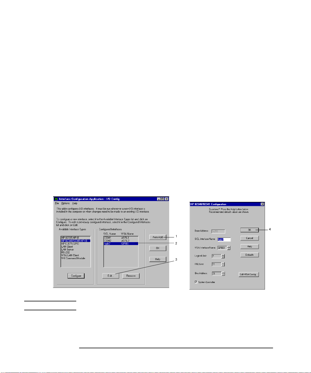
To Configure the Interface using HP I/O Library
After installing the IEEE 488 interface card and HP I/O Library, configure the
interface. The procedure shown below is the easiest way to configure the interface.
First, execute I_O Config in the HP I_O Libraries folder. The I/O Config window is
displayed. See Figure 1-1.
1. Click Auto A dd.
If the interface card is installed properly, I_O Config automatically detects the
hardware configuration. The default names for SICL and VISA are assigned and
listed, as shown in the Configured Interface list.
2. Click hpib7 GPIB0.
3. Click Edit to display the Configuration dialog box for the interface card.
If you find any conflicts in the dialog box, such as IRQ line, you may need to
change them manually. Normally you can exit without modifying the default
setup.
4. Click OK to exit. Reboot your PC to configure the interface.
Figure 1-1 To Configure the Interface using the HP I/O Library
NOTE VISA Name is used by the VXIplug&play drivers to access the interface.
20 Chapter 1
Page 21

Installation
Installing the HP 4155B/4156B Driver
To Install the Driver
1. Insert the HP 4155B/4156B Plug&Play Driver Disk into the flexible disk drive
connected to your PC.
2. Execute th e 4156B.EXE p rogram stored on the diskette. The program
automatically installs the driver in the following directory.
• For Windows NT: \Vxipnp\Winnt\Hp4156b
• For Win dows 95: \ Vx i pnp \Win95\Hp4156b
Following files are installed in the directory.
• hp4156b.bas
• hp4156b.c
• hp4156b.def
• hp4156b.fp
• hp4156b.GID
• hp4156b.h
• hp4156b.hlp
• readme.txt
•DelsL1.isu
3. If you are also installing the driver for the HP E5250A, do the following.
a. Ins e rt the HP E5 250A Plug&Play Driver Disk into the flexible disk drive
connected to your PC.
b. Execute the E5250A.EXE program stored on the diskette. The program
automatically installs the driver in the following directory.
• For Windows NT: \Vxipnp\Winnt\Hpe5250a
• For Win dows 95: \Vxipnp\W i n9 5\ Hpe5250a
Following files are installed in the directory.
• hpe5250a.bas
• hpe5250a.c
• hpe5250a.def
• hpe5250a.fp
Chapter 1 21
Page 22

Installation
Installing the HP 4155B/4156B Driver
• hpe5250a.GID
• hpe5250a.h
• hpe5250a.hlp
• readme.txt
•DelsL1.isu
22 Chapter 1
Page 23

2 Driver Functions
23
Page 24

Driver Functions
This section explains all the driver fincti ons available for the HP 41555B/415 6B and
the HP E5250A.
• “Driver Functions for HP 4155B/4156B”
• “Driver Functions for HP E5250A”
NOTE For additional information on each function. refer to the on-line help for the
VXIplug&play drivers, or open the hp4156b.hlp or hpe5250a.hlp file in the
direcroty the driver is installed. See “Installing the HP 4155B/4156B Driver” in
Chpater 1.
24 Chapter 2
Page 25

Driver Functions for HP 4155B/4156B
Table 2-1 lists all the functions for the HP 4155B/4156B. You will see a brief
description of the functions in th e table.
For the description, syntax and parameters of the function, refer to the reference
section following this table. The driver functions in the reference section will appear
in the alphabetical order.
Table 2-1 HP 4155B/4156B Driver Function Lists
Category Function Description
Miscellaneous hp4156b_init Initializes the HP 4155B/4156B.
hp4156b_close Closes the connection with the HP 4155B/4156B.
hp4156b_reset Executes the HP 4155B/4156B reset.
hp4156b_self_test Executes the HP 4155B/4156B self-test.
hp4156b_error_query Queries the HP 4155B/4156B for error code/ mess age.
hp4155b_error_message Queries for the driver errors.
hp4156b_revision_query Queries for HP 4155B/4156B firmware/driver revisions.
hp4156b_timeOut Sets the timeout.
hp4156b_timeOut_Q Queries for the timeout setting.
hp4156b_errorQueryDetect Sets the automatic error checking.
hp4156b_errorQueryDetect_Q Queries for the automatic error checking setting.
hp4156b_dcl Sends the Device Clear.
hp4156b_esr_Q Queries the ESR status.
hp4156b_readStatusByte_Q Reads the HP 4155B/4156B status byte.
hp4156b_opc_Q Checks HP 4155B/4156B operation completion status.
Primitive
Measurement
Functions
Calibration hp4156b_ a utoCal Sets the auto calibration mode
Zero Offset
Cancel
hp4156b_startMeasure Starts a measurement.
hp4156b_readData Reads a measurement result.
hp4156b_stopMode Sets the measurement completion mode.
hp4156b_abortMeasure Aborts output or measurement.
hp4156b_execCal Executes the HP 4155B/4156B calibration
hp4156b_offsetCancel Sets the zero offset cancel.
hp4156b_execOffsetCancel Executes the zero offset cancel.
Driver Functions
Chapter 2 25
Page 26

Driver Functions
Category Function Description
Measurement
Unit Setup
Source Setup hp4156b_force Applies a dc current or voltage.
Measurement
Execution
Sampling
Measurements
Stress Force hp4156b_setStress Sets the timing parameters.
hp4156b_setSwitch Sets the output switch.
hp4156b_setFilter Sets the output filter.
hp4156b_setInteg Sets the integration time.
hp4156b_setVm Sets the VMU measurement mode.
hp4156b_setPguR Sets the PGU output impedance.
hp4156b_forcePulse Applies a pulse by using PGU.
hp4156b_zeroOutput Disables output.
hp4156b_recoverOutput Recovers output.
hp4156b_setIv Sets the sweep source.
hp4156b_setPbias Sets the pulsed bias source.
hp4156b_setPiv Sets the pulsed sweep source.
hp4156b_setSweepSync Sets the synchronous sweep source.
hp4156b_spotMeas Executes a high speed spot measurement.
hp4156b_measureM Executes a multi-channel spot measurement.
hp4156b_sweepIv Executes a one channel sweep measurement.
hp4156b_sweepMiv Executes a multi-channel sweep measurement.
hp4156b_measureP Executes a pulsed spot measurement.
hp4156b_sweepPiv Executes a pulsed sweep measurement.
hp4156b_sweepPbias Executes a sweep measurement with pulsed bias.
hp4156b_setSample Sets the timing parameters.
hp4156b_addSampleSynclv Sets the dc source.
hp4156b_addSampleSyncPulse Sets the pulse source.
hp4156b_sample Executes a sampling measurement.
hp4156b_clearSampleSync Clears the source setup.
hp4156b_addStressSyncIv Sets the dc stress source.
hp4156b_addStressSyncPulse Sets the pulse stress source.
hp4156b_stress Forces stress.
hp4156b_clearStressSync Clears the source setup.
26 Chapter 2
Page 27

Category Function Description
Passthrough
Functions
hp4156b_cmd Sends a command.
h4156b_cmdInt Sends a command with an integer parameter.
hp4156b_cmdReal Sends a command with a real parameter.
hp4156b_cmdData_Q Sends a command to read any data.
hp4156b_cmdString_Q Sends a command to read string response.
hp4156b_cmdInt16_Q Sends a command to read 16 bit integer response.
hp4156b_cmdInt16Arr_Q Sends a command to read 16 bit integer array response.
hp4156b_cmdInt32_Q Sends a command to read 32 bit integer response.
hp4156b_cmdInt32Arr_Q Sends a command to read 32 bit integer array response.
hp4156b_cmdReal64_Q Sends a command to read 64 bit real response.
hp4156b_cmdReal64Arr_Q Sends a command to read 64 bit real array response.
Driver Functions
Chapter 2 27
Page 28

Driver Functions
hp4156b_abortMeasure
hp4156b_abortMeasure
This function aborts the HP 4155B /4156B’s present operation, such as the
measurement executed by the hp4156b_startMeasure function, the pulse output by
the hp4156b_forcePulse function, the stress force by the hp4156b_stress function,
and so on.
Syntax ViStatus _VI_FUNC hp4156b_abortMeasure(ViSession vi);
Parameters vi Instrument handle returned from hp4156b_init( ).
hp4156b_addSampleSyncIv
This function specifies the constant current source or constant voltage source used
for the sampling measurements, and sets the parameters. Source output starts at the
beginning of the sampling measurement (beginning of the hold time), and stops at
the end of the last sampling measurement point.
Sampling measurement channels are defined by the hp4156b_sample function, and
sampling measurement timing is defined by the hp4156b_setSample function.
Syntax ViStatus _VI_FUNC hp4156b_addSampleSyncIv(ViSession vi, ViInt32 channel,
ViInt32 mode, ViReal64 range, ViReal64 base, ViReal64 bias, ViReal64 comp);
Parameters vi Instrument handle returned from hp4156b_init( ).
channel Channel number of the source unit. 1 to 6 (SMU1 to SMU6),
21 (VSU1), 22 (VSU2), 27 (PGU1), or 28 (PGU2)
mode Output mode. 1 (current output, only for SMU) or 2 (voltage
output).
range Output range. 0 (auto ranging) or positive value (limited auto
ranging). See be low.
For current output: 1E-11 to 1.0 A, or 0.
For voltage output: 2.0 to 200.0 V, or 0.
base Base value. -1.0 to 1.0 A for curr ent output, -200.0 V to 200.0 V
for voltage output.
bias Bias value. -1.0 to 1.0 A for current ou tput, -200.0 V to 200.0 V
for voltage output.
comp Compliance valu e. -200. 0 V to 200.0 V for v oltage complian ce,
-1.0 to 1.0 A for current compliance.
28 Chapter 2
Page 29

Driver Functions
hp4156b_addSampleSyncPulse
hp4156b_addSampleSyncPulse
This function specifies the pulse source (PGU) used for the sampling measurements,
and sets the parameters. Pulse outputs start at the beginning of the sampling
measurement (beginning of the hold time), and stop at the end of the last sampling
measurement point or stop at the last pulse if it com e s earlier than the last sampling
measurement point.
Sampling measurement channels are defined by the hp4156b_sample function, and
sampling measurement timing is defined by the hp4156b_setSample function.
If you want to let the pulse output synchronize with the sampling measurement
timing, you should define carefully both the hp4156b_addSampleSyncPulse timing
parameters (count, period, width, delay, rise and fall) and the hp4156b_setSample
timing parameters.
Syntax ViS tatus _VI_FUNC hp4 156b_addSampleSyn cPulse(V iSessi on vi, V iInt32 chan nel,
ViReal64 base, ViReal64 peak, ViInt32 count, ViReal64 period, ViReal64 width,
ViReal64 delay, ViReal64 rise, ViReal64 fall);
Parameters vi Instrument handle returned from hp4156b_init( ).
channel Channel number of the pulse generator unit.
27 (PGU1) or 28 (PGU2)
base Pulse base value. -40.0 to 40.0 V.
peak Pulse peak value. -40.0 to 40.0 V.
count Pulse count (number of pulses). 1 to 65535, or 0 (free run
mode).
period Pulse period. 1E-6 to 1 0.0 seconds.
width Pulse width. 1E-6 to 9.99 seconds.
delay Pulse delay time. 0.0 to 10.0 seconds.
rise Pulse leading time. 0.1E-6 to 10E-3 secon ds.
fall Pulse trailling time. 0.1E-6 to 10E -3 seco nds.
Chapter 2 29
Page 30

Driver Functions
hp4156b_addStressSyncIv
hp4156b_addStressSyncIv
This function specifies the DC stress source, and sets the parameters. You can use
maximum 4 stress sources at once by using the hp4156b_ad dStressSyncIv and/or
hp4156b_addStressSyncPulse functions.
Syntax ViStatus _VI_FUNC hp4156b_addStressSyncIv(ViSession vi, ViInt32 source,
ViInt32 channel, ViInt32 mode, ViReal64 range, ViReal64 base, ViReal64 stress,
ViReal64 comp);
Parameters vi Instrument handle returned from hp4156b_init( ).
source Reference number of the stress source. 1, 2, 3, or 4.
channel Channel number of the stress source.
1 to 6 (SMU1 to SMU6), 21 (VSU1), 22 (VSU2), 27 (PGU1),
or 28 (PGU2)
mode Output mode. 1 (current output, only for SMU) or 2 (voltage
output).
range Output range. 0 (auto ranging) or positive value (limited auto
ranging). See be low.
For current output: 1E-11 to 1.0 A, or 0.
For voltage output: 2.0 to 200.0 V, or 0.
base Base value. -1.0 to 1.0 A for curr ent output, -200.0 V to 200.0 V
for voltage output.
stress Stress value. -1.0 to 1.0 A for current output, -200.0 V to 200.0
V for voltage output.
comp Compliance valu e. -200. 0 V to 200.0 V for v oltage complian ce,
-1.0 to 1.0 A for current compliance.
30 Chapter 2
Page 31

Driver Functions
hp4156b_addStressSyncPulse
hp4156b_addStressSyncPulse
This function specifies the pulse stress source (PGU), and sets the parameters. You
can use maximum 4 stress sources at once by using the hp4156b_addStressSyncIv
and/or hp4156b_addStressSyncPulse functions. See “hp4156b_stress” on page 63
for the setting of width and delay.
Syntax ViStatus _VI_FUNC hp4156b_addStressSyncPulse(ViSession vi, ViInt32 source,
ViInt32 channel, ViReal64 base, ViReal64 stress, ViReal64 width, ViReal64 delay,
ViReal64 rise, ViReal64 fall);
Parameters vi Instrument handle returned from hp4156b_init( ).
source Reference number of the stress source. 1, 2, 3, or 4.
channel Channel number of the pulse generator unit.
27 (PGU1) or 28 (PGU2)
base Stress pulse base value. -40.0 to 40.0 V.
stress Stress pulse peak value. -40.0 to 40.0 V.
width Pulse width. 1E-6 to 9.99 seconds.
delay Pulse delay time. 0.0 to 10.0 seconds.
rise Pulse leading time. 0.1E-6 to 10E-3 secon ds.
fall Pulse trailling time. 0.1E-6 to 10E -3 seco nds.
hp4156b_autoCal
This function enables or disables the auto calibration function.
Syntax ViStatus _VI_FUNC hp4156b_autoCal(ViSession vi, ViInt32 state);
Parameters vi Instrument handle returned from hp4156b_init( ).
state Auto calibration mode. 0 (OF F) or 1 (ON).
Chapter 2 31
Page 32

Driver Functions
hp4156b_clearSampleSync
hp4156b_clearSampleSync
This function clears the settings of the co nstant voltage/current source defined by
the hp4156b_addSampleSyncIv function, and the settings of the pulse source
defined by the hp4156b_addSampl eSy ncP ulse function.
Syntax ViStatus _VI_FUNC hp4156b_clearSampleSync(ViSession vi);
Parameters vi Instrument handle returned from hp4156b_init( ).
hp4156b_clearStressSync
This function clears the settings of the stress sources defined by the
hp4156b_addStressSyncIv function and the hp4156b_addStressSyncPulse function.
Syntax ViStatus _VI_FUNC hp4156b_clearStressSync(ViSession vi);
Parameters vi Instrument handle returned from hp4156b_init( ).
hp4156b_close
This function terminates the software connection to the instrument and deallocates
system resources. It is generally a good programming habit to close the instrument
handle when the program is done using the instrument.
Syntax ViStatus _VI_FUNC hp4156b_close(ViSession vi);
Parameters vi Instrument handle returned from hp4156b_init( ).
hp4156b_cmd
This function passes the cmd_str string to the instrument. Must be a NULL
terminated C string.
Syntax ViStatus _VI_FUNC hp4156b_cmd(ViSession vi, ViString cmd_str);
Parameters vi Instrument handle returned from hp4156b_init( ).
cmd_str Instrument command (cannot exceed 256 bytes in length).
32 Chapter 2
Page 33

Driver Functions
hp4156b_cmdData_Q
hp4156b_cmdData_Q
This function passes the cmd_str string to the instrumen t. This entry point will wait
for a response which may be any data. You specify the cmd_str and size parameters,
and get result[ ].
Syntax ViStatus _VI_FUNC hp4156b_cmdData_Q(ViSession vi, ViString cmd_str,
ViInt32 size, ViChar _VI_FAR result[ ] );
Parameters vi Instrument handle returned from hp4156b_init( ).
cmd_str Instrument command (cannot exceed 256 bytes in length).
size Length of result in bytes. 2 to 32767.
result[ ] Response from instrument.
hp4156b_cmdInt
This function passes the cmd_str string to the instrument. This entry point passes
the string in cmd_str followed by a space and then the integer in value. Note that
either an Int16 or 32 can be passed as the Int16 will be promoted.
Syntax ViStatus _VI_FUNC hp4156b_cmdInt(ViSession vi, ViString cmd_str,
ViInt32 value);
Parameters vi Instrument handle returned from hp4156b_init( ).
cmd_str Instrument command (cannot exceed 256 bytes in length).
value Parameter for command. -2147483647 to 2147483647.
Chapter 2 33
Page 34

Driver Functions
hp4156b_cmdInt16Arr_Q
hp4156b_cmdInt16Arr_Q
This function passes the cmd_str string to the instrument. This command expects a
response that is a definite arbitrary b lock of 16 bit integ ers . You specify t h e cmd _s tr
and size parameters, and get result[ ] and count.
Syntax ViStatus _VI_FUNC hp4156b_cmdInt16Arr_Q(ViSession vi, ViString cmd_str,
ViInt32 size, ViInt16 _VI_FAR result[ ], ViPInt32 count);
Parameters vi Instrument handle returned from hp4156b_init( ).
cmd_str Instrument command (cannot exceed 256 bytes in length).
size Size of result[ ] (number of items in the array).
1 to 2147483647.
result[ ] Response from instrument.
count Count of valid items in result[ ].
hp4156b_cmdInt16_Q
This function passes the cmd_str string to the instrument. This command expects a
response that can be returned as a 16 bit integer.
Syntax ViStatus _VI_FUNC hp4156b_cmdInt16_Q(ViSession vi, ViString cmd_str,
ViPInt16 result);
Parameters vi Instrument handle returned from hp4156b_init( ).
cmd_str Instrument command (cannot exceed 256 bytes in length).
result Response from instrument.
34 Chapter 2
Page 35

Driver Functions
hp4156b_cmdInt32Arr_Q
hp4156b_cmdInt32Arr_Q
This function passes the cmd_str string to the instrument. This command expects a
response that is a def in i te arbi trary block of 32 bi t i n teg e rs . You specify th e cmd _s tr
and size parameters, and get result[ ] and count.
Syntax ViStatus _VI_FUNC hp4156b_cmdInt32Arr_Q(ViSession vi, ViString cmd_str,
ViInt32 size, ViInt32 _VI_FAR result[ ], ViPInt32 count);
Parameters vi Instrument handle returned from hp4156b_init( ).
cmd_str Instrument command (cannot exceed 256 bytes in length).
size Size of result[ ] (number of items in the array).
1 to 2147483647.
result[ ] Response from instrument.
count Count of valid items in result[ ].
hp4156b_cmdInt32_Q
This function passes the cmd_str string to the instrument. This command expects a
response that can be returned as a 32 bit integer.
Syntax ViStatus _VI_FUNC hp4156b_cmdInt32_Q(ViSession vi, ViString cmd_str,
ViPInt32 result);
Parameters vi Instrument handle returned from hp4156b_init( ).
cmd_str Instrument command (cannot exceed 256 bytes in length).
result Response from instrument.
Chapter 2 35
Page 36

Driver Functions
hp4156b_cmdReal
hp4156b_cmdReal
This function passes the cmd_str string to the instrument. This entry point passes
the string in cmd_str followed by a space and then the real in value. Note that either
an Real32 or 64 can be passed as the Real32 will be promoted.
Syntax ViStatus _VI_FUNC hp4156b_cmdReal(ViSession vi, ViString cmd_str,
ViReal64 value);
Parameters vi Instrument handle returned from hp4156b_init( ).
cmd_str Instrument command (cannot exceed 256 bytes in length).
value Parameter for command. -1E+300 to 1E+300.
hp4156b_cmdReal64Arr_Q
This function passes the cmd_str string to the instrument. This command expects a
response that is a definite arbitrary block of 64 bit reals. You specify the cmd_str
and size parameters, and get result[ ] and count.
Syntax ViStatus _VI_FUNC hp4156b_cmdReal64Arr_Q(ViSession vi, ViString cmd_str,
ViInt32 size, ViReal64 _VI_FAR result[ ], ViPInt32 count);
Parameters vi Instrument handle returned from hp4156b_init( ).
cmd_str Instrument command (cannot exceed 256 bytes in length).
size Size of result[ ] (number of items in the array).
1 to 2147483647.
result[ ] Response from instrument.
count Count of valid items in result[ ].
36 Chapter 2
Page 37

Driver Functions
hp4156b_cmdReal64_Q
hp4156b_cmdReal64_Q
This function passes the cmd_str string to the instrument. This command expects a
response that can be returned as a 64 bit real.
Syntax ViStatus _VI_FUNC hp4156b_cmdReal64_Q(ViSession vi, ViString cmd_str,
ViPReal64 result);
Parameters vi Instrument handle returned from hp4156b_init( ).
cmd_str Instrument command (cannot exceed 256 bytes in length).
result Response from instrument.
hp4156b_cmdString_Q
This function passes the cmd_str string to the instrumen t. This entry point will wait
for a response which must be a string (character data). You specify the cmd_str and
size parameters, and get result[ ].
Syntax ViStatus _VI_FUNC hp4156b_cmdString_Q(ViSession vi, ViString cmd_str,
ViInt32 size, ViChar _VI_FAR result[ ] );
Parameters vi Instrument handle returned from hp4156b_init( ).
cmd_str Instrument command (cannot exceed 256 bytes in length).
size Length of result in bytes. 2 to 32767.
result[ ] Response from instrument.
hp4156b_dcl
This function sends a device clear (DCL) to the instrument.
A device clear will abort the present operation and enable the instrument to accept a
new command or query. This is particularly useful in situations where it is not
possible to determine the instrument state. In this case, it is cu stomary to send a
device clear before issuing a new instrument driver function. The device clear
ensures that the instrument will be able to begin processing the new commands.
Syntax ViStatus _VI_FUNC hp4156b_dcl(ViSession vi);
Parameters vi Instrument handle returned from hp4156b_init( ).
Chapter 2 37
Page 38

Driver Functions
hp4156b_error_message
hp4156b_error_message
This function translates the error return value from an instrument dri ver func tion to
a readable string.
Syntax ViS tatus _ VI_FUNC h p4156b_err or_message( ViSession vi, Vi Stat us error_ number ,
ViChar _VI_FAR message[ ] );
Parameters vi Instrument handle returned from hp4156b_init( ).
error_number Error return value from the driver function.
message[ ] Error message string. This is limited to 256 characters.
hp4156b_error_query
This function returns the error numbers and corresponding error messages in the
error queue of a instrument. See HP 4155B/4156B User’s Guide: Measurement and
Analysis for a listing of the instrument error numbers and messages.
Instrument errors may occur when you places the instrument in a bad state such as
sending an invalid sequence of coupled commands. Instrument errors can be
detected by polling. Automatic polling can be accomplished by using the
hp4156b_errorQueryDetect function.
Syntax ViStatus _VI_FUNC hp4156b_error_query(ViSession vi, ViPInt32 error_number,
ViChar _VI_FAR error_message[ ] );
Parameters vi Instrument handle returned from hp4156b_init( ).
error_number Instrument’s error code.
error_message[ ] Instrument’s error message. This is limited to 256 characters.
38 Chapter 2
Page 39

Driver Functions
hp4156b_errorQueryDetect
hp4156b_errorQueryDetect
This function enables or disables automatic instrument error checking.
If automatic error checking is enabled then the driver will query the instru men t for
an error at the end of each function call.
Syntax ViStatus _VI_FUNC hp4156b_errorQueryDetect(ViSession vi,
ViBoolean errorQueryDetect);
Parameters vi Instrument handle returned from hp4156b_init( ).
errorQueryDetect Error checking enable (VI_TRUE) or disable (VI_FALSE).
hp4156b_errorQueryDetect_Q
This function indicates if automatic instrument error d e tection is enabled or
disabled.
Syntax ViStatus _VI_FUNC hp4156b_errorQueryDetect_Q(ViSession vi,
ViPBoolean pErrDetect);
Parameters vi Instrument handle returned from hp4156b_init( ).
pErrDetect Error checking enable (VI_TRUE) or disable (VI_FALSE).
Chapter 2 39
Page 40

Driver Functions
hp4156b_esr_Q
hp4156b_esr_Q
This function returns the contents of the ESR regis ter. The driver returns the
equivalent messages:
Syntax ViStatus _VI_FUNC hp4156b_esr_Q(ViSession vi, ViChar _VI_FAR errstr[ ] );
Parameters vi Instrument handle returned from hp4156b_init( ).
errstr[ ] Response from instrument.
Bit Value Message
1 “ESR_OPC”
2 “ESR_RQL”
4 “ESR_QYE”
8 “ESR_DDE”
16 “ESR_EXE”
32 “ESR_CME”
64 “ESR_URQ”
128 “ESR_PON”
hp4156b_execCal
This function executes the calibration and returns the calibration result. The
parameter “result” returns the calibration result.
Syntax ViStatus _VI_FUNC hp4156b_execCal(ViSession vi, ViPInt32 result);
Parameters vi Instrument handle returned from hp4156b_init( ).
result Calibration result. Numeric number.
0: No error (calibration succeed).
40 Chapter 2
Page 41

Driver Functions
hp4156b_execOffsetCancel
hp4156b_execOffsetCancel
This function measures the zero offset data, and sets the zero offset function to ON.
The parameter ’channel’ specifies the measurement channel (SMU or VMU).
If you define SMU for ’channel’, the SMU must be set to the voltage force mode by
using the hp415 6b_force function, before executing this functi on.
If you define VMU for 'channel’, the VMU must be set to the differential voltage
measurement mode by using the hp4156b_setVm function, before executing this
function.
Syntax ViStatus _VI_FUNC hp4156b_execOffsetCancel(ViSession vi, ViInt32 channel,
ViInt32 range);
Parameters vi Instrument handle returned from hp4156b_init( ).
channel Channel number of the unit to measure the zero offset data..
1 to 6 (SMU1 to SMU6), 23 (VMU1), or 24 (VMU2).
range Measurement range to measure the zero offset data
0 (10 pA range for SMU), 1 (100 pA range for SMU),
2 (1 nA range for SMU), or 3 (0.2 V range for VMU).
Chapter 2 41
Page 42

Driver Functions
hp4156b_force
hp4156b_force
This function specifies the dc current source (SMU) or dc voltage source (SMU,
VSU, or PGU), and forces the output immediately. To stop the output, use the
hp4156b_force function with 0 (zero) output.
Syntax ViStatus _VI_FUNC hp4156b_force(ViSession vi, ViInt32 channel, ViInt32 mode,
ViReal64 range, ViReal64 value, ViReal64 comp, ViInt32 polarity);
Parameters vi Instrument handle returned from hp4156b_init( ).
channel Channel number of the source unit.
1 to 6 (SMU1 to SMU6), 21 (VSU1), 22 (VSU2), 27 (PGU1),
or 28 (PGU2)
mode Output mode. 1 (current output, only for SMU) or 2 (voltage
output).
range Output range. 0 (auto ranging) or positive value (limited auto
ranging). See be low.
For current output: 1E-11 to 1.0 A, or 0.
For voltage output: 2.0 to 200.0 V, or 0.
value Output value. -1.0 to 1.0 A for current output, -20 0.0 to 200.0 V
for SMU voltage outp ut, -40 t o 40 V fo r PGU dc vol tage output,
-20 to 20 V for VSU output.
comp Compliance value (only for SMU). -200.0 V to 200.0 V for
voltage compliance, -1.0 to 1.0 A for current compliance.
polarity Compliance polarity (only for SMU). 0 (auto) or 1 (manual).
If you select 1, polarity is set to the same polarity as comp value
you enterd.
42 Chapter 2
Page 43

Driver Functions
hp4156b_forcePulse
hp4156b_forcePulse
This function specifies the pulse source (PGU) settings and forces the voltage pulse
immediately. To stop the pulse output, use hp4156b_abortMeasure function.
Syntax ViStatus _VI_FUNC hp4156b_forcePulse(ViSession vi, ViInt32 channel,
ViInt32 count, ViReal64 base, ViReal64 peak, ViReal64 width, ViReal64 period,
ViReal64 delay, ViReal64 rise, ViReal64 fall);
Parameters vi Instrument handle returned from hp4156b_init( ).
channel Channel number of the pulse generator unit.
27 (PGU1) or 28 (PGU2)
count Pulse count (number of pulses). 1 to 65535, or 0 (free run
mode).
base Pulse base value. -40.0 to 40.0 V.
peak Pulse peak value. -40.0 to 40.0 V.
width Pulse width. 1E-6 to 9.99 seconds.
period Pulse period. 1E-6 to 1 0.0 seconds.
delay Pulse delay time. 0.0 to 10.0 seconds.
rise Pulse leading time. 0.1E-6 to 10E-3 secon ds.
fall Pulse trailling time. 0.1E-6 to 10E -3 seco nds.
Chapter 2 43
Page 44

Driver Functions
hp4156b_init
hp4156b_init
This function initializes the softwa re co nnection to the instrument and optionally
verifies that instrument is in the system. In addition, it may perform any necessary
actions to place the instrument in its reset state.
If the hp4156b_init function encounters an error, then the value of the vi output
parameter will be VI_NULL.
Syntax ViStatus _VI_FUNC hp4156b_init(ViRsrc InstrDesc, ViBoolean id_query,
ViBoolean do_reset, ViPSession vi);
Parameters InstrDesc Instrument description. Examples; GPIB0::1::INSTR.
id_query VI_TRUE (to perform system verification), or
VI_FA LSE (do not perform system verification).
do_reset VI_TRUE (to perform reset operation), or
VI_FALSE (do not perform reset operation).
vi Instrument handle. This is VI_NULL if an error occurred
during the init.
44 Chapter 2
Page 45

Driver Functions
hp4156b_measureM
hp4156b_measureM
This function executes a multi channel spot measurement by the specified units, and
returns the measured value and the measurement status.
The array size of all arrays should be the same together. Then the order of the array
data is important. For example, the measurement setup for the unit specified by
channel[1] must be entered into mode[1] and range[1]. And the measured data and
status data of the units specified by channel[1] will be returned by value[1] and
status[1], respectively.
Syntax ViStatus _VI_FUNC hp4156b_measureM(ViSession vi, ViInt32 channel[ ],
ViInt32 mode[ ], ViReal64 range[ ], ViReal64 value[ ], ViInt32 status[ ] );
Parameters vi Instrument handle returned from hp4156b_init( ).
channel[ ] Channel number of the measurement unit. Enter 0 (zero) at the
end of the unit definition for channel[ ]. For example, if you use
two units, the first and second elements of channel[ ] must
specify the units, and the third element must be 0.
1 to 6 (SMU1 to SMU6), 23 (VMU1), or 24 (VMU2).
mode[ ] Measurement mode.
1 (current measurement) or 2 (voltage measurement).
range[ ] Measurement range. 0 (auto ranging), positive value (limited
auto ranging), or negative value (fixed r ange). See below.
For current measurement: -1E-11 to -1.0 A, 1E-11 to 1.0 A,
or 0.
For voltage measurement: -2.0 to -200.0 V, 2.0 to 200.0 V
(-0.2 and 0.2 are available for
VMU in differential mode), or 0.
value[ ] Measurement data.
status[ ] Measurement status. 0 (no error), or 1 to 255 (error status).
Chapter 2 45
Page 46

Driver Functions
hp4156b_measureP
hp4156b_measureP
This function executes a pulsed spot measurement by the specified channel, and
returns the measured value and the measurement status.
Syntax ViStatus _VI_FUNC hp4156b_measureP(ViSession vi, ViInt32 channel,
ViInt32 mode, ViReal64 range, ViPReal64 value, ViPInt32 status);
Parameters vi Instrument handle returned from hp4156b_init( ).
channel Channel number of the measurement unit.
1 to 6 (SMU1 to SMU6), 23 (VMU1), or 24 (VMU2).
mode Measurement mod e. 1 (cur rent measurem ent, only for SMU) or
2 (voltage measurement).
range Measurement range. 0 (auto ranging), positive value (limited
auto ranging), or negative value (fixed r ange). See below.
For current measurement: -1E-11 to -1.0 A, 1E-11 to 1.0 A,
or 0.
For voltage measurement: -2.0 to -200.0 V, 2.0 to 200.0 V
(-0.2 and 0.2 are available for
VMU in differential mode), or 0.
value Measurement data.
status Measurement status. 0 (no error), or 1 to 255 (error status).
hp4156b_offsetCancel
This function enables or disables the zero offset cancel function.
Syntax ViStatus _VI_FUNC hp4156b_offsetCancel(ViSession vi, ViInt32 channel,
ViInt32 state);
Parameters vi Instrument handle returned from hp4156b_init( ).
channel Channel number of the unit to set the offset cancel function.
1 to 6 (SMU1 to SMU6), 23 (VMU1), or 24 (VMU2).
state 0 (Function OFF), or 1 (Function ON).
46 Chapter 2
Page 47

Driver Functions
hp4156b_opc_Q
hp4156b_opc_Q
This function does the *OPC? common command.
Syntax ViStatus _VI_FUNC hp4156b_opc_Q(ViSession vi, ViPBoolean result);
Parameters vi Instrument handle returned from hp4156b_init( ).
result VI_TRUE (Operation complete), or
VI_FALSE (Operation is pending).
hp4156b_readData
This function reads and returns the source setup data or the data measured by the
hp4156b_startMeasure function.
Syntax ViStatus _VI_FUNC hp4156b_readData(ViSession vi, ViPInt32 eod,
ViPInt32 data_type, ViPReal64 value, ViPInt32 status, ViPInt32 channel);
Parameters vi Instrument handle returned from hp4156b_init( ).
eod End of data flag. 0 (not end of data), or 1 (end of data).
data_type Data type of the v alue. 0 (Volt age setup data),
1 (Current setup data), 3 (Time setup data),
8 (Vo ltage measurement data), 9 (Current measurement data),
11 (T ime meas uremen t data), 14 (Sampli ng in dex data), or
15 (Stress status data ).
value Measurement data or source setup data.
status Measurement status or source status.
channel Channel number of the unit for measurement or output.
1 to 6 (SMU1 to SMU6), 21 (VSU1), 22 (VSU2), 23(VMU1),
24 (VMU2), 27 (PGU1) or 28 (PGU2).
Chapter 2 47
Page 48

Driver Functions
hp4156b_readStatusByte_Q
hp4156b_readStatusByte_Q
This function returns the contents of the status byte register.
Syntax ViStatus _VI_FUNC hp4156b_readStatusByte_Q(ViSession vi,
ViPInt16 statusByte);
Parameters vi Instrument handle returned from hp4156b_init( ).
statusByte The contents of the status byte are returned in this parameter.
hp4156b_recoverOutput
This function returns the unit to the settings that are stored by the
hp4156b_zeroOutput function, and clears the stored unit settings.
Syntax ViStatus _VI_FUNC hp4156b_recoverOutput(ViSession vi, ViInt32 channel);
Parameters vi Instrument handle returned from hp4156b_init( ).
channel Channel number of the unit to return the settings. 1 to 6 (SMU1
to SMU6), 21 (VSU1), 22 (VSU2), 27 (PGU1) or 28 (PGU2).
hp4156b_reset
This function places the instrument in a default state. Before issuing this fu nction, it
may be necessary to send a device clear to en sure that the instrum ent can execute a
reset. A device clear can be issued by invoking hp4156b_dcl function.
Syntax ViStatus _VI_FUNC hp4156b_reset(ViSession vi);
Parameters vi Instrument handle returned from hp4156b_init( ).
48 Chapter 2
Page 49

Driver Functions
hp4156b_revision_query
hp4156b_revision_query
This function returns the driver revision and the instrume nt firmware revision.
Syntax ViStatus _VI_FUNC hp4156b_revision_query(ViSession vi,
ViChar_VI_FAR driver_rev[ ] , ViChar _VI_FAR instr_rev[ ] );
Parameters vi Instrument handle returned from hp4156b_init( ).
driver_rev[ ] Instrument driver revision. This is limited to 256 characters.
instr_rev[ ] Instrument firmware revision. This is limited to 256 characters.
Chapter 2 49
Page 50

Driver Functions
hp4156b_sample
hp4156b_sample
This function executes a sampling measurement by the specified channels, and
returns the number of measurement points, measurement data index, measurement
data and the measurement status.
Before executing this function, set the sampling timing by using the
hp4156b_setSample function. The synchronous dc sources used with the sampling
measurement units are defined by using the hp4156b_addSampleSyncIv function.
And the synchronous pulsed sources used with the sampling measurement units are
defined by using the hp4156b_addSampleSyncPulse function.
Syntax ViStatus _VI_FUNC hp4156b_sample(ViSession vi, ViInt32 channel[ ],
ViInt32 mode[ ], ViReal64 range[ ], ViPInt32 point, ViInt32 index[ ],
ViReal64 value[ ], ViInt32 status[ ] );
Parameters vi Instrument handle returned from hp4156b_init( ).
channel[ ] Channel number of the measurement unit.
1 to 6 (SMU1 to SMU6), 23 (VMU1), or 24 (VMU2).
mode[ ] Measurement mode. 1 (current meas urement , only for S MU) or
2 (voltage measurement).
range[ ] Measurement range. 0 (auto ranging), positive value (limited
auto ranging), or negative value (fixed r ange). See below.
For current measurement: -1E-11 to -1.0 A, 1E-11 to 1.0 A,
or 0.
For voltage measurement: -2.0 to -200.0 V, 2.0 to 200.0 V
(-0.2 and 0.2 are available for
VMU in differential mode), or 0.
point Number of measurement points. 1 to 10001.
index[ ] Measurement data index.
value[ ] Measurement data.
status[ ] Measurement status. 0 (no error), or 1 to 255 (error status).
50 Chapter 2
Page 51

Remarks The array size of the parameters should be as shown below.
ViInt32 channel[N]
ViInt32 mode[N]
ViReal64 range[N]
ViInt32 point
ViInt32 index[M]
ViReal64 value[M][N]
ViReal64 status[M][N]
where,
N: Number of channels used for the measurements plus 1, or more.
M: Number of sweep points ('point’ parameter value of hp4156b_setSample
function), or more.
For the parameter definition, the order of the array data is important. For example,
the measurement setup for the unit specified by channel[1] must be entered into
mode[1] and range[1]. And measurement data and status data of the unit specified
by channel[1] will be returned by value[M][1] and status[M][1], respectively.
Driver Functions
hp4156b_self_test
hp4156b_self_test
This function causes the instrument to perform a self-test and returns the result of
that self-test. This is used to verify that an instrument is operating properly. A failure
may indicate a potential hardware problem.
Syntax ViStatus _VI_FUNC hp4156b_self_test(ViSession vi, ViPInt16 test_result,
ViChar_VI_FAR test_message[ ] );
Parameters vi Instrument handle returned from hp4156b_init( ).
test_result Numeric result from self-test operation. 0: No error.
test_message[ ] Self-test status message. This is limited to 256 characters.
Chapter 2 51
Page 52

Driver Functions
hp4156b_setFilter
hp4156b_setFilter
This function sets the output filter of the specified channel.
Syntax ViStatus _VI_FUNC hp4156b_setFilter(ViSession vi, ViInt32 channel,
ViInt32 state);
Parameters vi Instrument handle returned from hp4156b_init( ).
channel Channel number of the unit. 1 (SMU1), 2, 3, 4, 5, or 6 (SMU6).
state 0 (Filter OFF) or 1 (Filter ON).
hp4156b_setInteg
This function sets the integration time, and sets the number of samples that are taken
and averaged for the measurement.
Syntax ViStatus _VI_FUNC hp4156b_setInteg(ViSession vi, ViInt32 table, ViReal64 time,
ViInt32 average);
Parameters vi Instrument handle returned from hp4156b_init( ).
table Integration time table. 1 (short), 2 (medium), or 3 (long).
time Integration time. in seconds. 80E-6 to 10.16E-3 for table=1, or
16.7E-3 to 2.0 for table=3. Ignore this parameter for table=2.
average Number of samples for averaging. 1 t o 1023, or 0. If you do not
want to change the value from previous value, enter 0.
52 Chapter 2
Page 53

Driver Functions
hp4156b_setIv
hp4156b_setIv
This function specifies the sweep source channel for the staircase sweep measurements and the staircase sweep with pulsed bias measurements, and sets the parameters. For the staircase sweep with pulsed bias measurements, the sweep output
synchronizes with the pulse outpu t by the hp415 6b_ set P bi as funct i on.
Syntax ViStatus _VI_FUNC hp4156b_setIv(ViSession vi, ViInt32 channel, ViInt32 mode,
ViReal64 range, ViReal64 start, ViReal64 stop, ViInt32 point, ViReal64 hold,
ViReal64 delay, ViReal64 s_delay, ViReal64 comp, ViReal64 p_comp);
Parameters vi Instrument handle returned from hp4156b_init( ).
channel Channel number of the sweep source.
1 to 6 (SMU1 to SMU6), 21 (VSU1), or 22 (VSU2).
mode Outp ut mode. 1 (single linear), 2 (single log), 3 (double linear),
or 4 (double log). Use positive value for voltage output, use
negative value for current output (only for SMU).
range Output range. 0 (auto ranging) or positive value (limited auto
ranging). See be low.
For current output: 1E-11 to 1.0 A, or 0.
For voltage output: 2.0 to 200.0 V, or 0.
start Sweep start value. -1.0 to 1.0 A, or -200.0 to 200.0 V.
stop Sweep stop value. -1.0 to 1.0 A, or -200.0 to 200.0 V.
point Number of sweep steps. 1 to 1001.
hold Hold time. 0 to 655.35 seconds.
delay Delay time. 0 to 65.535 seconds.
s_delay Step delay time. 0 to 1.0 second.
comp Compliance valu e. -200. 0 V to 200.0 V for v oltage complian ce,
-1.0 to 1.0 A for current compliance.
p_comp Power compliance. 1.0 to 20.0.
Chapter 2 53
Page 54

Driver Functions
hp4156b_setPbias
hp4156b_setPbias
This function specifies the pulse output channel for the pulsed spot measurements
and the staircase sweep with pulsed bias measurements, and sets the parameters.
For the staircase sweep with pulsed bias measurements, the pulse output
synchronizes with the staircase sweep output by the hp4156b_setIv function.
Syntax ViStatus _VI_FUNC hp4156b_setPbias(ViSession vi, ViInt32 channel,
ViInt32 mode, ViReal64 range, ViReal64 base, ViReal64 peak, ViReal64 width,
ViReal64 period, ViReal64 hold, ViReal64 comp);
Parameters vi Instrument handle returned from hp4156b_init( ).
channel Channel number of the pulse source.
1 to 6 (SMU1 to SMU6), 21 (VSU1), or 22 (VSU2).
mode Pulse output mode. 1 (current output, only for SMU), or
2 (voltage output).
range Output range. 0 (auto ranging) or positive value (limited auto
ranging). See be low.
For current output: 1E-11 to 1.0 A, or 0.
For voltage output: 2.0 to 200.0 V, or 0.
base Pulse base value. -1.0 to 1.0 A, or -200.0 to 200.0 V.
peak Pulse peak value. -1.0 to 1.0A, or -200.0 to 200.0 V.
width Pulse width. 0.5E-3 to 100E-3 seconds.
period Pulse period. 5E-3 to 1.0 seconds.
hold Hold time. 0.0 to 655.35 seconds.
comp Compliance valu e. -200. 0 V to 200.0 V for v oltage complian ce,
-1.0 to 1.0 A for current compliance.
54 Chapter 2
Page 55

Driver Functions
hp4156b_setPguR
hp4156b_setPguR
This function sets the PGU output im pedance.
Syntax ViStatus _VI_FUNC hp4156b_setPguR(ViSession vi, ViInt32 channel,
ViInt32 state);
Parameters vi Instrument handle returned from hp4156b_init( ).
channel Channel number of PGU.
27 (PGU1) or 28 (PGU2).
state PGU output impedance.
0 (approx. 0 ohm low impedance) or 1 (50 ohm).
Chapter 2 55
Page 56

Driver Functions
hp4156b_setPiv
hp4156b_setPiv
This function specifies the pulsed sweep source channel for the pulsed sweep
measurements, and sets the parameters.
Syntax ViS tat us _VI _FUNC hp41 56b_s etPiv( ViSession vi, V iInt 32 chan nel, ViInt32 mode,
ViReal64 range, ViReal64 base, Vi Real64 start, ViReal64 stop, ViInt32 point,
ViReal64 hold, ViReal64 width, ViReal64 period, ViReal64 comp);
Parameters vi Instrument handle returned from hp4156b_init( ).
channel Channel number of the pulse sweep source.
1 to 6 (SMU1 to SMU6), 21 (VSU1), or 22 (VSU2).
mode Outp ut mode. 1 (si ng le linear), 2 (single log), 3 (double linear),
or 4 (double log). Use positive value for voltage output , use
negative value for current output (only for SMU).
range Output range. 0 (auto ranging) or positive value (limited auto
ranging). See be low.
For current output: 1E-11 to 1.0 A, or 0.
For voltage output: 2.0 to 200.0 V, or 0.
base Pulse sweep base value. -1.0 to 1.0 A, or -200.0 to 200.0 V.
start Pulse sweep start value. -1.0 to 1.0A, or -200.0 to 200.0 V.
stop Pulse sweep stop value. -1.0 to 1.0A, or -200.0 to 200.0 V.
point Number of sweep steps. 1 to 1001.
hold Hold time. 0.0 to 655.35 seconds.
width Pulse width. 0.5E-3 to 100E-3 seconds.
period Pulse period. 5E-3 to 1.0 seconds.
comp Compliance valu e. -200. 0 V to 200.0 V for v oltage complian ce,
-1.0 to 1.0 A for current compliance.
56 Chapter 2
Page 57

Driver Functions
hp4156b_setSample
hp4156b_setSample
This function specifies the measurement timing of the samplin g measur ements. Th e
sampling measurement units are defined by the hp4156b_sample function.
Syntax ViStatus _VI_FUNC hp4156b_setSample(ViSession vi, ViReal64 hold,
ViReal64 interval, ViInt32 point);
Parameters vi Instrument handle returned from hp4156b_init( ).
hold Hold time. -30E-3 to 655.35 seconds.
interval Sampling interval. 60E-6 to 65.534 seconds.
point Number of sampling points. 1 to 10001.
hp4156b_setStress
This function sets the timing parameters of the stress. See “hp4156b_stress” on
page 63 for the setting of period parameter.
Syntax ViStatus _VI_FUNC hp4156b_setStress(ViSession vi, ViReal64 hold,
ViInt32 mode, ViReal64 duration, ViReal64 period);
Parameters vi Instrument handle returned from hp4156b_init( ).
hold Hold time. 0 to 655.35 seconds.
mode Stress mode. 1 (pulse count mode) or 2 (duration mode).
duration Number of pulse count (1 to 65535) for mode=1, or
Duration time (500E-6 to 655.0 seconds) for mode=2.
period Pulse period. 2E-6 to 1 0.0 seconds.
Chapter 2 57
Page 58

Driver Functions
hp4156b_setSweepSync
hp4156b_setSweepSync
This function specifies the synchronous sweep source channel for the staircase
sweep measurements, the pulsed sweep measurements and the staricase sweep with
pulsed bias measurements, and sets the parameters. Synchronous sweep source is
used for the staircase sweep.
For the staircase sweep measurements, the output synchronizes with the staircase
sweep output by the hp4156b_setIv function.
For the pulsed sweep measurements, the output synchronizes with the pulsed sweep
output by the hp4156b_setPiv function.
For the staircase sweep with pulsed bias measurements, the output synchronizes the
staircase sweep output by the hp4156b_setIv function and the pulse output by the
hp4156b_setPbias function.
Syntax ViStatus _VI_FUNC hp4156b_setSweepSync(ViSession vi, ViInt32 channel,
ViInt32 mode, ViReal64 range, ViReal64 start, ViReal64 stop, ViReal64 comp,
ViReal64 p_comp);
Parameters vi Instrument handle returned from hp4156b_init( ).
channel Channel number of the sweep source.
1 to 6 (SMU1 to SMU6), 21 (VSU1), or 22 (VSU2).
mode Output mode. 1 (current output, only for SMU) or
2 (voltage output).
range Output range. 0 (auto ranging) or positive value (limited auto
ranging). See be low.
For current output: 1E-11 to 1.0 A, or 0.
For voltage output: 2.0 to 200.0 V, or 0.
start Sweep start value. -1.0 to 1.0 A, or -200.0 to 200.0 V.
stop Sweep stop value. -1.0 to 1.0 A, or -200.0 to 200.0 V.
comp Compliance valu e. -200. 0 V to 200.0 V for v oltage complian ce,
-1.0 to 1.0 A for current compliance.
p_comp Power compliance. 1.0 to 20.0.
58 Chapter 2
Page 59

Driver Functions
hp4156b_setSwitch
hp4156b_setSwitch
This function sets the output switch of the specified channel.
Syntax ViStatus _VI_FUNC hp4156b_setSwitch(ViSession vi, ViInt32 channel,
ViInt32 state);
Parameters vi Instrument handle returned from hp4156b_init( ).
channel Channel number of the unit.
1 to 6 (SMU1 to SMU6), 21 (VSU1), 22 (VSU2), 23 (VMU1),
24 (VMU2), 26 (GNDU), 27 (PGU1) or 28 (PGU2).
state Output switch setting.
0 (output switch OFF) or 1 (output switch ON).
hp4156b_setVm
This function sets the VMU measurement mode.
Syntax ViStatus _VI_FUNC hp4156b_setVm(ViSession vi, ViInt32 mode);
Parameters vi Instrument handle returned from hp4156b_init( ).
mode VMU measurement mode.
1 (grounded mode) or 2 (differential mode).
Chapter 2 59
Page 60

Driver Functions
hp4156b_spotMeas
hp4156b_spotMeas
This function executes a high speed spot measuremen t by the specified channel, and
returns the measured value and the measurement status.
Syntax ViStatus _VI_FUNC hp4156b_spotMeas(ViSession vi, ViInt32 channel,
ViInt32 mode, ViReal64 range, ViPReal64 value, ViPInt32 status);
Parameters vi Instrument handle returned from hp4156b_init( ).
channel Channel number of the measurement unit.
1 to 6 (SMU1 to SMU6), 23 (VMU1), or 24 (VMU2).
mode Measurement mode.
1 (current measurement, only for SMU) or
2 (voltage measurement).
range Measurement range.
0 (auto ranging), positive value (limited auto ranging), or
negative value (fixed range). See below.
For current measurement: -1E-11 to -1.0 A, 1E-11 to 1.0 A,
or 0.
For voltage measurement: -2.0 to -200.0 V, 2.0 to 200.0 V
(-0.2 and 0.2 are available for
VMU in differential mode), or 0.
value Measurement data.
status Measurement status. 0 (no error), or 1 to 255 (error status).
60 Chapter 2
Page 61

Driver Functions
hp4156b_startMeasure
hp4156b_startMeasure
This function starts the specified measurement by the specified channels. You can
read the measured data by using the hp415 6b_readData f unction. Th e measurement
data is entered to the HP4155B/4156B output buffer in the measurement order. If
you want to abort the measurement, use the hp4156b_abortMeasure function.
The array size of all arrays should be the same together. Then the order of the array
data is important. For example, the measurement setup for the unit specified by
channel[1] must be entered into mode[1] and range[1].
Syntax ViStatus _VI_FUNC hp4156b_startMeasure(ViSession vi, ViInt32 meas_type,
ViInt32 channel[ ], ViInt32 mode[ ], ViReal64 range[ ], ViInt32 source);
Parameters vi Instrument handle returned from hp4156b_init( ).
meas_type Measurement type. 1 (multi spot), 2 (staircase sweep),
3 (pulse spot), 4 (pulse sweep), 5 (sweep with pulsed bias),
10 (sampling), or 11 (stress force).
channel[ ] Channel number of the measurement unit. Enter 0 (zero) at the
end of the unit definition for channel[ ]. For example, if you use
two units, the first and second elements of channel[ ] must
specify the units, and the third element must be 0.
1 to 6 (SMU1 to SMU6), 23 (VMU1), or 24 (VMU2).
mode[ ] Measurement mode. 1 (current meas urement , only for S MU) or
2 (voltage measurement).
range[ ] Measurement range. 0 (auto ranging), positive value (limited
auto ranging), or negative value (fixed r ange). See below.
For current measurement: -1E-11 to -1.0 A, 1E-11 to 1.0 A,
or 0.
For voltage measurement: -2.0 to -200.0 V, 2.0 to 200.0 V
(-0.2 and 0.2 are available for
VMU in differential mode), or 0.
source Source data output mode.
0 (measurement data output without source data) or
1 (measurement data output with source data).
Chapter 2 61
Page 62

Driver Functions
hp4156b_stopMode
hp4156b_stopMode
This function specifies the stop condition which enables the automatic abort
function for the sweep measurement, sampling measurement, or stress force. Also
this function specifies the sweep source output of the measurement unit after the
sweep measurement is aborted.
Syntax ViStatus _VI_FUNC hp4156b_stopMode(ViSession vi, ViInt32 occ_stop,
ViInt32 tcc_stop, ViInt32 ovf_stop, ViInt32 osc_stop, ViInt32 last_mode);
Parameters vi Instrument handle returned from hp4156b_init( ).
occ_stop Automatic abort function by comp liance of another unit.
0 (disables this abort mode) or 1 (enables this abort mode).
tcc_stop Automatic abort function by compliance of this unit.
0 (disables this abort mode) or 1 (enables this abort mode).
ovf_stop Automatic abort function by overflow of AD converter.
0 (disables this abort mode) or 1 (enables this abort mode).
osc_stop Automatic abort function by oscillation of unit(s).
0 (disables this abort mode) or 1 (enables this abort mode).
last_mode Source output value after abort condition.
1 (returns to start value), or 2 (keeps the value when aborted).
62 Chapter 2
Page 63

Driver Functions
hp4156b_stress
hp4156b_stress
This function forces the stress defined by the hp4156b_setStress,
hp4156b_addStressSyncIv, and hp4156b_addStressSyncPulse functions.
Syntax ViStatus _VI_FUNC hp4156b_stress(ViSession vi, ViPInt32 status);
Parameters vi Instrument handle returned from hp4156b_init( ).
status Stress output status. 0 (no error), or 1 to 255 (error status).
Remarks The following parameters must be set within the range shown in the following table.
The period is a parameter of hp4156b_setStress function. And width and delay are
parameters of hp4156b_addStressSyncPulse function.
period width delay
2E-6 to 100E-6 sec 1E-6 to 99.9E-6 sec 0 to 100E-6 sec
100E-6 to 1E-3 sec 1E-6 to 999E-6 sec 0 to 1E-3 sec
1E-3 to 10E-3 sec 10E-6 to 9.99E-3 sec 0 to 10E-3 sec
10E-3 to 100E-3 sec 100E-6 to 99.9E-3 sec 0 to 100E-3 sec
100E-3 to 1.0 sec 1E-3 to 999E-3 sec 0 to 1.0 sec
1.0 to 10.0 sec 10E-3 to 9.99 sec 0 to 10.0 sec
Chapter 2 63
Page 64

Driver Functions
hp4156b_sweepIv
hp4156b_sweepIv
This function executes a staircase sweep measurement by the specified channel, and
returns the number of measurement points, sweep source data, measurement data
and the measurement status.
Before executing this function, set the sweep sour ce setup by using the
hp4156b_setIv funct ion. If you want to us e th e syn chro nous sweep source, execute
the hp4156b_setSweepSync function.
The array size of source, value and status should be the same together, and it must be
greater than or equal to the number of sweep points defined by the hp4156b_setIv
function ('point’ parameter).
Syntax ViStatus _VI_FUNC hp4156b_sweepIv(ViSession vi, ViInt32 channel,
Vi In t3 2 mode, ViReal64 range, ViPInt32 point, V iReal 64 so urce[ ],
ViReal64 value[ ], ViInt32 status[ ] );
Parameters vi Instrument handle returned from hp4156b_init( ).
channel Channel number of the measurement unit.
1 to 6 (SMU1 to SMU6), 23 (VMU1), or 24 (VMU2).
mode Measurement mod e. 1 (cur rent measurem ent, only for SMU) or
2 (voltage measurement).
range Measurement range. 0 (auto ranging), positive value (limited
auto ranging), or negative value (fixed r ange). See below.
For current measurement: -1E-11 to -1.0 A, 1E-11 to 1.0 A,
or 0.
For voltage measurement: -2.0 to -200.0 V, 2.0 to 200.0 V
(-0.2 and 0.2 are available for
VMU in differential mode), or 0.
point Number of measurement points. 1 to 1001.
source[ ] Sweep source setup data.
value[ ] Measurement data.
status[ ] Measurement status. 0 (no error), or 1 to 255 (error status).
64 Chapter 2
Page 65

Driver Functions
hp4156b_sweepMiv
hp4156b_sweepMiv
This function executes a multichannel staircase sweep measurement by the specified
channels, and returns the number of measurement points, sweep source data,
measurement data and the measurement status.
Before executing this function, set the sweep sour ce setup by using the
hp4156b_setIv function. If you want to use the synchronous sweep source, execute
the hp4156b_setSweepSync function.
Syntax ViStatus _VI_FUNC hp4156b_sweepMiv(ViSession vi, ViInt32 channel[ ],
ViInt32 mode[ ], ViReal64 range[ ], ViPInt32 point, ViReal64 source[ ] ,
ViReal64 value[ ], ViInt32 status[ ] );
Parameters vi Instrument handle returned from hp4156b_init( ).
channel[ ] Channel number of the measurement unit. Enter 0 (zero) at the
end of the unit definition for channel[ ]. For example, if you use
two units, the first and second elements of channel[ ] must
specify the units, and the third element must be 0.
1 to 6 (SMU1 to SMU6), 23 (VMU1), or 24 (VMU2).
mode[ ] Measurement mode. 1 (current meas urement , only for S MU) or
2 (voltage measurement).
range[ ] Measurement range. 0 (auto ranging), positive value (limited
auto ranging), or negative value (fixed r ange). See below.
For current measurement: -1E-11 to -1.0 A, 1E-11 to 1.0 A,
or 0.
For voltage measurement: -2.0 to -200.0 V, 2.0 to 200.0 V
(-0.2 and 0.2 are available for
VMU in differential mode), or 0.
point Number of measurement points. 1 to 1001.
source[ ] Sweep source setup data.
value[ ] Measurement data. Tw o dimentional array.
status[ ] Measurement status. 0 (no error), or 1 to 255 (error status).
Two dimensional array.
Chapter 2 65
Page 66

Driver Functions
hp4156b_sweepMiv
Remarks The array size of the parameters should be as shown below.
ViInt32 channel[N]
ViInt32 mode[N]
ViReal64 range[N]
ViInt32 point
ViReal64 source[M]
ViReal64 value[M][N]
ViReal64 status[M][N]
where,
N: Number of channels used for the measurements plus 1, or more.
M: Number of sweep points ('point’ parameter value of hp4156b_setIv function),
or more.
For the parameter definition, the order of the array data is important. For example,
the measurement setup for the unit specified by channel[1] must be entered into
mode[1] and range[1]. And measurement data and status data of the unit specified
by channel[1] will be returned by value[M][1] and status[M][1], respectively.
66 Chapter 2
Page 67

Driver Functions
hp4156b_sweepPbias
hp4156b_sweepPbias
This function executes a staircase sweep with pulsed bias measurement by the
specified channel, and returns the number of measurement points, sweep source
data, measurement data, and the measurement status. Before executing this function,
set the sweep source setup and pulsed bias setup by using the hp4156b_setIv
function and the hp4156b_setPbias function. If you want to use the synchronous
sweep source, execute the hp4156b_setSweepSync function.
The array size of source, value and status should be the same together, and it must be
greater than or equal to the number of sweep points defined by the hp4156b_setIv
function ('point’ parameter).
Syntax ViStatus _VI_FUNC hp4156b_sweepPbias(ViSession vi, ViInt32 channel,
Vi In t3 2 mode, ViReal64 range, ViPInt32 point, ViR eal64 source[ ] ,
ViReal64 value[ ], ViInt32 status[ ] );
Parameters vi Instrument handle returned from hp4156b_init( ).
channel Channel number of the measurement unit.
1 to 6 (SMU1 to SMU6), 23 (VMU1), or 24 (VMU2).
mode Measurement mod e. 1 (cur rent measurem ent, only for SMU) or
2 (voltage measurement).
range Measurement range. 0 (auto ranging), positive value (limited
auto ranging), or negative value (fixed r ange). See below.
For current measurement: -1E-11 to -1.0 A, 1E-11 to 1.0 A,
or 0.
For voltage measurement: -2.0 to -200.0 V, 2.0 to 200.0 V
(-0.2 and 0.2 are available for
VMU in differential mode), or 0.
point Number of measurement points. 1 to 1001.
source[ ] Sweep source setup data.
value[ ] Measurement data.
status[ ] Measurement status. 0 (no error), or 1 to 255 (error status).
Chapter 2 67
Page 68

Driver Functions
hp4156b_sweepPiv
hp4156b_sweepPiv
This function executes a pulsed sweep measurement by the specified channel, and
returns the number of measurement points, sweep source data, measurement value
and the measurement status.
Array size of source, value and status should be the same together, and it must be
greater than or equal to the number of sweep points defined by the hp4156b_setPiv
function ('point’ parameter).
Before executing this function, set the pulsed sweep source setup by using the
hp4156b_setPiv function. If you want to use the synchronous sweep source,
execute the hp4156b_setSweepSync function.
Syntax ViStatus_VI_FUNC hp4156b_sweepPiv(ViSession vi, ViInt32 channel,
Vi In t3 2 mode, ViReal64 range, ViPInt32 point, V iReal 64 so urce[ ],
ViReal64 value[ ], ViInt32 status[ ] );
Parameters vi Instrument handle returned from hp4156b_init( ).
channel Channel number of the measurement unit.
1 to 6 (SMU1 to SMU6), 23 (VMU1), or 24 (VMU2).
mode Measurement mod e. 1 (cur rent measurem ent, only for SMU) or
2 (voltage measurement).
range Measurement range. 0 (auto ranging), positive value (limited
auto ranging), or negative value (fixed r ange). See below.
For current measurement: -1E-11 to -1.0 A, 1E-11 to 1.0 A,
or 0.
For voltage measurement: -2.0 to -200.0 V, 2.0 to 200.0 V
(-0.2 and 0.2 are available for
VMU in differential mode), or 0.
point Number of measurement points. 1 to 1001.
source[ ] Sweep source setup data.
value[ ] Measurement data.
status[ ] Measurement status. 0 (no error), or 1 to 255 (error status).
68 Chapter 2
Page 69

Driver Functions
hp4156b_timeOut
hp4156b_timeOut
This function sets a minimum timeout v a lue for driver I/O transactions in
milliseconds. The default timeout period is 5 seconds.
Syntax ViStatus_VI_FUNC hp4156b_timeOut(ViSession vi, ViInt32 timeOut);
Parameters vi Instrument handle returned from hp4156b_init( ).
timeOut I/O timeout value for all functions in the driver. in milliseconds.
0 to 2147483647.
hp4156b_timeOut_Q
This function returns the timeout value for driver I/O transactions in milliseconds.
Syntax ViStatus_VI_FUNC hp4156b_ti meOu t_ Q(ViSession vi, ViPInt32 pTimeOut);
Parameters vi Instrument handle returned from hp4156b_init( ).
pTimeOut Minimum timeout period that the driver can be set to, in
milliseconds.
hp4156b_zeroOutput
This function stores the measurement setup of the units, and sets the units to 0 V
output. To recover the setup, execute hp4156b_recoverOutput function.
Syntax ViStatus_VI_FUNC hp4156b_zetoOutput(ViSession vi, ViInt32 channel);
Parameters vi Instrument handle returned from hp4156b_init( ).
channel Channel number of the unit to set to the zero output.
0 (all unit), 1 to 6 (SMU1 to SMU6), 21 (VSU1), 22 (VSU2),
27 (PGU1), or 28 (PGU2).
Chapter 2 69
Page 70

Driver Functions
hp4156b_zeroOutput
Driver Functions for HP E5250A
Table 2-2 lists all the functions for the HP E5250A. You will see a brief description
of the functions in the table.
For the description, syntax and parameters of the function, refer to the reference
section following this table. The driver functions in the reference section will appear
in the alphabetical order.
Table 2-2 HP E5250A Driver Fu nction Lists
Category Function Description
Miscellaneous hpe5250a_init Initializes the HP E5250A.
hpe5250a_close Closes the connection with the HP E5250A.
hpe5250a_reset Executes the HP E5250A reset.
hpe5250a_self_test Executes the HP E5250A self-test.
hpe5250a_error_query Queries for the HP E5250A error code/message.
hpe5250a_error_message Queries for the driver error.
hpe5250a_revision_query Queries for the HP E5250A firmware/driver revisions.
hpe5250a_timeOut Sets the timeout.
hpe5250a_timeOut_Q Queries for the timeout setting.
hpe5250a_errorQueryDetect Sets the automatic error checking.
hpe5250a_errorQueryDetect_Q Queries for the automatic error checking setting.
hpe5250a_dcl Sends the Device Clear.
hpe5250a_esr_Q Queries for the ESR status.
hpe5250a_readStatusByte_Q Reads the HP E5250A status byte.
hpe5250a_opc_Q Checks the HP E5250A operation completion status.
Mode Control hpe5250a_func Sets the configuration mode.
hpe5250a_connRuleSeq Sets the connection rule/sequence.
Bias Mode hpe5250a_biasPort Selects the input bias port.
hpe5250_biasChanCard Selects the card for bias mode.
hpe5250_biasChanList Selects the channel list for bias mode.
hpe5250a_biasState Sets the bias port state.
hpe5250a_biasChanList_Q Queries for the bias channel list.
Couple Port hpe5250a_couplePort Selects the couple port.
hpe5250a_coupleState Sets the couple port state.
70 Chapter 2
Page 71

Driver Functions
hp4156b_zeroOutput
Category Function Description
Route Control hpe5250a_closeList Closes the channel list.
hpe5250a_openList Opens the channel list.
hpe5250a_openCard Opens all output on the card.
hpe5250a_closeList_Q Queries for the channel list status.
hpe5250a_openList_Q
hpe5250a_closeCard_Q Queries for the closed channel list on the card.
C/G
Compensation
Diagnostics hpe5250a_testExec_Q Executes the relay/front-panel/controller test.
Passthrough
Functions
hpe5250a_CompenC Executes the C/G compensation.
hpe5250a_selectCompenFile Selects the compensation data file.
hpe5250a_testClear Clears the test result.
hpe5250a_cmd Sends a command.
hpe5250a_cmdInt Sends a command with an integer parameter.
hpe5250a_cmdReal Sends a command with a real parameter.
hpe5250a_cmdData_Q Sends a command to read any data.
hpe5250a_cmdString_Q Sends a command to read string response.
hpe5250a_cmdInt16_Q Sends a command to read 16 bit integer response.
hpe5250a_cmdInt16Arr_Q Sends a command to read 16 bit integer array response.
hpe5250a_cmdInt32_Q Sends a command to read 32 bit integer response.
hpe5250a_cmdInt32Arr_Q Sends a command to read 32 bit integer array response.
hpe5250a_cmdReal64_Q Sends a command to read 64 bit real response.
hpe5250a_cmdReal64Arr_Q Sends a command to read 64 bit real array response.
Chapter 2 71
Page 72

Driver Functions
hpe5250a_biasChanCard
hpe5250a_biasChanCard
This function will enable or disable bias on all the output ports of the specified card.
Syntax ViStatus _VI_FUNC hpe5250a_biasChanCard(ViSession vi,
Vi In t1 6 disable_enable, ViInt16 bias_cardno);
Parameters vi Instrument handle returned from hpe5250a_init( ).
disable_enable Bi as status. 0 (enables bias) or 1 (disables bias).
bias_cardno Card number. 1 (card 1), 2 (card 2), 3 (card 3), 4 (card 4), or 5
(all card) in the normal configur ation mode, or 0 (all card in th e
automatic configur ation mode). For the configurati on mode, see
hpe5250a_func.
hpe5250a_biasChanList
This function will enable or disable bias on all the output ports specified by the
biaschan_list.
The parameter ’biaschan_list’ is an array of integers with each integer representing
one channel. The last number of the ’biaschan_list’ should be "0" (numeric zero)
to identify the end of the list. The maximum number of channels that can be
specified by the list is 100.
Syntax ViStatus _VI_FUNC hpe5250a_biasChanList(ViSession vi,
ViInt16 biaschan_disen, Vi Int32 _VI_FAR biaschan_list[ ] );
Parameters vi Instrument handle returned from hpe5250a_init( ).
biaschan_disen Bias status. 0 (enables bias) or 1 (disables bias).
biaschan_list[ ] Channel numbers. 5 digits integer. ABCDE. where A: card
number, BC: input port number, DE: output port number.
Top zero(s) can be ignored. For example, if A=0, BC=01, and
DE=01, channel number should be 101 instead of 00101.
72 Chapter 2
Page 73

Driver Functions
hpe5250a_biasChanList_Q
hpe5250a_biasChanList_Q
This function will query the instrument for th e bias statu s for th e channels given in
the list.
The parameter ’biaschan_list’ is an array of integers with each integer representing
one channel. The last number of the ’biaschan_list’ should be "0" (numeric zero)
to identify the end of the list. The maximum number of channels that can be
specified by the list is 100.
The ’bias_status’ parameter is an array of integers containing th e return va lues of
the query. The ’bias_status’ array returned will correspond one to one with
’biaschan_list’ parameter.
Syntax ViStatus _VI_FUNC hpe5250a_biasChanList_Q(ViSession vi, ViInt16 bias_disen,
ViInt32 _VI_FAR biaschan_list[ ], ViInt32 _VI_FAR bias_status[ ] );
Parameters vi Instrument handle returned from hpe5250a_init( ).
bias_disen Bias status for the query. 0 (bias enabled) or 1 (bias disabled).
biaschan_list[ ] Channel numbers to know the bias status. 5 digits integer.
ABCDE. where A: card number, BC: input port number, DE:
output port number. Top zero(s) can be ignored. For example, if
A=0, BC=01, and DE=01, channel number should be 101
instead of 00101.
bias_status[ ] Bias status of the channels given in the biaschan_list.
0 (bias enabled) or 1 (bias disabled).
Chapter 2 73
Page 74

Driver Functions
hpe5250a_biasPort
hpe5250a_biasPort
This function will select which input port is the bias port on the specified card. For
each card, you can specify the same or different Bias Port. This function applies
only to HP E5252A card.
Syntax ViStatus _VI_FUNC hpe5250a_biasPort(ViSession vi, ViInt16 biasport_cardno,
ViInt16 bias_port);
Parameters vi Instrument handle returned from hpe5250a_init( ).
biasport_cardno Card number. 1 (card 1), 2 (card 2), 3 (card 3), 4 (card 4), or 5
(all card) in the normal configur ation mode, or 0 (all card in th e
automatic configur ation mode). For the configurati on mode, see
hpe5250a_func.
bias_port Input port number to be s et to the bias po rt. 1 t o 10 (inp ut po rt 1
to input port 10).
hpe5250a_biasState
This function controls the bias mode for the specified card. When Bias Mode is ON,
the input Bias Port is connected to all bias enabled output ports that are not
connected to any other input ports. Bi as disabled output ports are never co nnected to
the input Bias Port when Bias Mode is ON.
Syntax ViStatus _VI_FUNC hpe5250a_biasState(ViSession vi, ViInt16 biasstate_cardno,
ViInt16 state);
Parameters vi Instrument handle returned from hpe5250a_init( ).
biasstate_cardno Card number. 1 (card 1), 2 (card 2), 3 (card 3), 4 (card 4), or 5
(all card) in the normal configur ation mode, or 0 (all card in th e
automatic configur ation mode). For the configurati on mode, see
hpe5250a_func.
state Bias mode. 0 (OFF) or 1 (ON).
74 Chapter 2
Page 75

Driver Functions
hpe5250a_close
hpe5250a_close
This function terminates the software connection to the instrument and deallocates
system resources. It is generally a good programming habit to close the instrument
handle when the program is done using the instrument.
Syntax ViStatus _VI_FUNC hpe5250a_close(ViSession vi);
Parameters vi Instrument handle returned from hpe5250a_init( ).
hpe5250a_closeCard_Q
This function will query the card for the channels closed of the specified card.
The parameter ’closechan_list’ contains the channel numbers returned by the
instrument. This will be an array of integers terminated by ’zero’ to identify the end
of the list. Array of enough length should be passed to the function.
Syntax ViStatus _VI_FUNC hpe5250a_closeCard_Q(ViSession vi, ViInt16 close_card,
ViInt32 _VI_FAR closechan_list[ ] );
Parameters vi Instrument handle returned from hpe5250a_init( ).
close_card Card number. 1 (card 1), 2 (card 2), 3 (card 3), or 4 (card 4) in
the normal configuration mode, or 0 (all card in the automatic
configuration mode). For the configuration mode, see
hpe5250a_func.
closechan_list[ ] Channels closed of the specified card.
Chapter 2 75
Page 76

Driver Functions
hpe5250a_closeList
hpe5250a_closeList
This function will connect the input ports to the output ports specified by the
channel list.
The parameter ’closechan_list’ is an array of integers with each integer representing
one channel. The last number of the ’closechan_list’ shou ld be "0 " (nu meric zero )
to identify the end of the list. The maximum number of channels that can be
specified by the list is 100.
Syntax ViStatus _VI_FUNC hpe5250a_closeList(ViSession vi,
ViInt32_VI_FAR closechan_list[ ] );
Parameters vi Instrument handle returned from hpe5250a_init( ).
closechan_list[ ] Channel numbers to connect. 5 digits integer. ABCDE. where
A: card number, BC: input port number, DE: output port
number. Top zero(s) can be ignored. For example, if A=0,
BC=01, and DE=01, channel number should be 101 instead of
00101.
76 Chapter 2
Page 77

Driver Functions
hpe5250a_closeList_Q
hpe5250a_closeList_Q
This function will query the instrum e nt for the channels closed given in the
’closechan_list’.
The parameter ’closechan_list’ is an array of integers with each integer representing
one channel. The last number of the ’closechan_list’ should be "0 " (nu meric zero)
to identify the end of the list. The maximum number of channels that can be
specified by the list is 100.
The ’close_status’ parameter is an array of integers containing th e return va lues of
the query. The ’close_status’ array returned will correspond one to one with
’closechan_list’ parameter.
Syntax ViStatus _VI_FUNC hpe5250a_closeList_Q(ViSession vi,
ViInt32_VI_FAR closechan_list[ ], ViInt32 _VI_FAR close_status[ ] );
Parameters vi Instrument handle returned from hpe5250a_init( ).
closechan_list[ ] Channel numbers to know the close status. 5 digits integer.
ABCDE. where A: card number, BC: input port number, DE:
output port number. Top zero(s) can be ignored. For example, if
A=0, BC=01, and DE=01, channel number should be 101
instead of 00101.
close_status[ ] Status of the channels given in the closechan_list.
0 (opened) or 1 (closed).
hpe5250a_cmd
This function passes the cmd_str string to the instrument. Must be a NULL
terminated C string.
Syntax ViStatus _VI_FUNC hpe5250a_cmd(ViSession vi, ViString cmd_str);
Parameters vi Instrument handle returned from hpe5250a_init( ).
cmd_str Instrument command (cannot exceed 256 bytes in length).
Chapter 2 77
Page 78

Driver Functions
hpe5250a_cmdData_Q
hpe5250a_cmdData_Q
This function passes the cmd_str string to the instrumen t. This en try point will wait
for a response which may be any data. You specify the cmd_str and size parameters,
and get result[ ].
Syntax ViStatus _VI_FUNC hpe5250a_cmdData_Q(ViSession vi, ViString cmd_str,
ViInt32 size, ViChar _VI_FAR result[ ] );
Parameters vi Instrument handle returned from hpe5250a_init( ).
cmd_str Instrument command (cannot exceed 256 bytes in length).
size Length of result in bytes. 2 to 32767.
result[ ] Response from instrument.
hpe5250a_cmdInt
This function passes the cmd_str string to the instrument. This entry point passes
the string in cmd_str followed by a space and then the integer in value. Note that
either an Int16 or 32 can be passed as the Int16 will be promoted.
Syntax ViStatus _VI_FUNC hpe5250a_cmdInt(ViSession vi, ViString cmd_str,
ViInt32 value);
Parameters vi Instrument handle returned from hpe5250a_init( ).
cmd_str Instrument command (cannot exceed 256 bytes in length).
value Parameter for command. -2147483647 to 2147483647.
78 Chapter 2
Page 79

Driver Functions
hpe5250a_cmdInt16Arr_Q
hpe5250a_cmdInt16Arr_Q
This function passes the cmd_str string to the instrument. This command expects a
response that is a def in i te arbi trary block of 16 bi t i n teg e rs . You specify the cmd_str
and size parameters, and get result[ ] and count.
Syntax ViStatus _VI_FUNC hpe5250a_cmdInt16Arr_Q(ViSession vi, ViString cmd_str,
ViInt32 size, ViInt16 _VI_FAR result[ ], ViPInt32 count);
Parameters vi Instrument handle returned from hpe5250a_init( ).
cmd_str Instrument command (cannot exceed 256 bytes in length).
size Size of result[ ] (number of items in the array).
1 to 2147483647.
result[ ] Response from instrument.
count Count of valid items in result[ ].
hpe5250a_cmdInt16_Q
This function passes the cmd_str string to the instrument. This command expects a
response that can be returned as a 16 bit integer.
Syntax ViStatus _VI_FUNC hpe5250a_cmdInt16_Q(ViSession vi, ViString cmd_str,
ViPInt16 result);
Parameters vi Instrument handle returned from hpe5250a_init( ).
cmd_str Instrument command (cannot exceed 256 bytes in length).
result Response from instrument.
Chapter 2 79
Page 80

Driver Functions
hpe5250a_cmdInt32Arr_Q
hpe5250a_cmdInt32Arr_Q
This function passes the cmd_str string to the instrument. This command expects a
response that is a definite arbitrary b lock of 32 bit integ ers . You specify the cmd_str
and size parameters, and get result[ ] and count.
Syntax ViStatus _VI_FUNC hpe5250a_cmdInt32Arr_Q(ViSession vi, ViString cmd_str,
ViInt32 size, ViInt32 _VI_FAR result[ ], ViPInt32 count);
Parameters vi Instrument handle returned from hpe5250a_init( ).
cmd_str Instrument command (cannot exceed 256 bytes in length).
size Size of result[ ] (number of items in the array).
1 to 2147483647.
result[ ] Response from instrument.
count Count of valid items in result[ ].
hpe5250a_cmdInt32_Q
This function passes the cmd_str string to the instrument. This command expects a
response that can be returned as a 32 bit integer.
Syntax ViStatus _VI_FUNC hpe5250a_cmdInt32_Q(ViSession vi, ViString cmd_str,
ViPInt32 result);
Parameters vi Instrument handle returned from hpe5250a_init( ).
cmd_str Instrument command (cannot exceed 256 bytes in length).
result Response from instrument.
80 Chapter 2
Page 81

Driver Functions
hpe5250a_cmdReal
hpe5250a_cmdReal
This function passes the cmd_str string to the instrument. This entry point passes
the string in cmd_str followed by a space and then the real in value. Note that either
an Real32 or 64 can be passed as the Real32 will be promoted.
Syntax ViStatus _VI_FUNC hpe5250a_cmdReal(ViSession vi, ViString cmd_str,
ViReal64 value);
Parameters vi Instrument handle returned from hpe5250a_init( ).
cmd_str Instrument command (cannot exceed 256 bytes in length).
value Parameter for command. -1E+300 to 1E+300.
hpe5250a_cmdReal64Arr_Q
This function passes the cmd_str string to the instrument. This command expects a
response that is a definite arbitrary block of 64 bit reals. You specify the cmd_str
and size parameters, and get result[ ] and count.
Syntax ViStatus _VI_FUNC hpe5250a_cmdReal64Arr_Q(ViSession vi, ViString cmd_str,
ViInt32 size, ViReal64 _VI_FAR result[ ], ViPInt32 count);
Parameters vi Instrument handle returned from hpe5250a_init( ).
cmd_str Instrument command (cannot exceed 256 bytes in length).
size Size of result[ ] (number of items in the array).
1 to 2147483647.
result[ ] Response from instrument.
count Count of valid items in result[ ].
Chapter 2 81
Page 82

Driver Functions
hpe5250a_cmdReal64_Q
hpe5250a_cmdReal64_Q
This function passes the cmd_str string to the instrument. This command expects a
response that can be returned as a 64 bit real.
Syntax ViStatus _VI_FUNC hpe5250a_cmdReal64_Q(ViSession vi, ViString cmd_str,
ViPReal64 result);
Parameters vi Instrument handle returned from hpe5250a_init( ).
cmd_str Instrument command (cannot exceed 256 bytes in length).
result Response from instrument.
hpe5250a_cmdString_Q
This function passes the cmd_str string to the instrumen t. This en try point will wait
for a response which must be a string (character data). You specify the cmd_str and
size parameters, and get result[ ].
Syntax ViStatus _VI_FUNC hpe5250a_cmdString_Q(ViSession vi, ViString cmd_str,
ViInt32 size, ViChar _VI_FAR result[ ] );
Parameters vi Instrument handle returned from hpe5250a_init( ).
cmd_str Instrument command (cannot exceed 256 bytes in length).
size Length of result in bytes. 2 to 32767.
result[ ] Response from instrument.
82 Chapter 2
Page 83

Driver Functions
hpe5250a_compenC
hpe5250a_compenC
This function compensates capacitance/conductance data measured by using
HP4284A C meter, and returns compensation results. If you change the compensation data, create the compensation data file, and specify the data file using
hpe5250a_selectCompenFile function before executing this function.
Syntax ViStatus _VI_FUNC hpe5250a_compenC(ViSession vi,ViReal64 frequency,
ViReal64 len_hptrx, ViReal64 len_usrtrx_h, ViReal64 len_usrtrx_l,
Vi Real 6 4 len_usrcoax_h, V iReal 64 len_usrcoax_l, ViReal64 raw_c,
ViReal64 raw_g, ViPReal64 compen_c, ViPReal64 compen_g);
Parameters vi Instrument handle returned from hpe5250a_init( ).
frequency Measurement frequency. 1E3 to 1E6 Hz.
len_hptrx HP 16494A cable length. 1.5 or 3.0 m.
len_usrtrx_h Triaxial cable length (in m) between connector plate and DUT
high terminal. If you do not use triaxial cable, enter 0 (zero).
len_usrtrx_l Triaxial cable length (in m) between connector plate and DUT
low terminal. If you do not use triaxial cable, enter 0 (zero).
len_usrcoax_h Coaxial cable length (in m) between connector plate and DUT
high terminal. If you do not use coaxial cable, enter 0 (zero).
len_usrcoax_l Coaxial cable length (in m) between connector plate and DUT
low terminal. If you do not use coaxial cable, enter 0 (zero).
raw_c Capacitance value (in F) measured by the HP 4284A.
raw_g Conductance value (in S) measured by the HP 4284A.
compen_c Capacitance compensation result (in F).
compen_g Conductance compensation result (in S).
Chapter 2 83
Page 84

Driver Functions
hpe5250a_connRuleSeq
hpe5250a_connRuleSeq
The function sets connection rule and connection sequence for the specified card.
Syntax ViStatus _VI_FUNC hpe5250a_connRuleSeq(ViSession vi,
ViInt16 cardno_ruleseq, ViInt16 rule, ViInt16 sequence);
Parameters vi Instrument handle returned from hpe5250a_init( ).
cardno_ruleseq Card number. 1 (card 1), 2 (card 2), 3 (card 3), 4 (card 4), or 5
(all card) in the normal configur ation mode, or 0 (all card in th e
automatic configur ation mode). For the configurati on mode, see
hpe5250a_func.
rule Connection rule. 0 (free route) or 1 (single route).
sequence Connection sequence. 0, 1, or 2. See below.
0 (no sequence)
1 (break before make)
2 (make before break)
84 Chapter 2
Page 85

Driver Functions
hpe5250a_couplePort
hpe5250a_couplePort
This function sets the couple ports which are used for making kelvin connections on
the specified card. The specified input port number will be coupled with the next
input port and two output ports. For each card, you may setup the same or diff erent
couple ports. This command overwrites the previous couple port setting for the card.
This command applies only to HP E5252A card.
The couple port mode is controlled by the hpe5250a_coupleState function.
Syntax ViStatus _VI_FUNC hpe5250a_couplePort(ViSession vi,
ViInt16 coupleport_cardno, ViInt16 port1, ViInt16 port3, ViInt16 port5,
ViInt16 port7, ViInt16 port9);
Parameters vi Instrument handle returned from hpe5250a_init( ).
coupleport_cardno Card number. 1 (card 1), 2 (card 2), 3 (card 3), 4 (card 4), or 5
(all card) in the normal configur ation mode, or 0 (all card in th e
automatic configur ation mode). For the configurati on mode, see
hpe5250a_func.
port1 Couple port by the input ports 1 and 2.
0 (disable) or 1 (enable).
port3 Couple port by the input ports 3 and 4.
0 (disable) or 1 (enable).
port5 Couple port by the input ports 5 and 6.
0 (disable) or 1 (enable).
port7 Couple port by the input ports 7 and 8.
0 (disable) or 1 (enable).
port9 Couple port by the input ports 9 and 10.
0 (disable) or 1 (enable).
Chapter 2 85
Page 86

Driver Functions
hpe5250a_coupleState
hpe5250a_coupleState
This function controls the couple port mode for the specified card. This function
applies only to HP E5252A card.
Syntax ViStatus _VI_FUNC hpe5250a_coupleState(ViSession vi,
Vi In t1 6 couplestate_cardno, ViInt16 couple_stat e);
Parameters vi Instrument handle returned from hpe5250a_init( ).
couplestate_cardno Card number. 1 (card 1), 2 (card 2), 3 (card 3), 4 (card 4), or 5
(all card) in the normal configur ation mode, or 0 (all card in th e
automatic configur ation mode). For the configurati on mode, see
hpe5250a_func.
couple_state Couple port mode. 0 (OFF) or 1 (ON).
hpe5250a_dcl
This function sends a device clear (DCL) to the instrument.
A device clear will abort the present operation and enable the instrument to accept a
new command or query.
This is particularly useful in situations where it is not possible to determine the
instrument state. In this case, it is customary to send a device clear before issuing a
new instrument driver function. The device clear ensures that the instrum ent will be
able to begin processing the new commands.
Syntax ViStatus _VI_FUNC hpe5250a_dcl(ViSession vi);
Parameters vi Instrument handle returned from hpe5250a_init( ).
86 Chapter 2
Page 87

Driver Functions
hpe5250a_error_message
hpe5250a_error_message
This function translates the error return value from an instrument dri ver func tion to
a readable string.
Syntax ViStatus _VI_FUNC hpe5250a_error_message(ViSession vi, ViStatus
error_number, ViChar _VI_FAR message[ ] );
Parameters vi Instrument handle returned from hpe5250a_init( ).
error_number Error return value from the driver function.
message[ ] Error message string. This is limited to 256 characters.
hpe5250a_error_query
This function returns the error numbers and corresponding error messages in the
error queue of a instrument. See HP E5250A User’s Guide for a listing of the
instrument error numbers and messages.
Instrument errors may occur when you places the instrument in a bad state such as
sending an invalid sequence of coupled commands. Instrument errors can be
detected by polling. Automatic polling can be accomplished by using the
hpe5250a_errorQueryDetect functio n.
Syntax ViStatus _VI_FUNC hpe5250a_error_query(ViSession vi, ViPInt32 error_number,
ViChar _VI_FAR error_message[ ] );
Parameters vi Instrument handle returned from hpe5250a_init( ).
error_number Instrument’s error code.
error_message[ ] Instrument’s error message. This is limited to 256 characters.
Chapter 2 87
Page 88

Driver Functions
hpe5250a_errorQueryDetect
hpe5250a_errorQueryDetect
This function enables or disables automatic instrument error checking.
If automatic error checking is enabled then the driver will query the instru men t for
an error at the end of each function call.
Syntax ViStatus _VI_FUNC hpe5250a_errorQueryDetect(ViSession vi,
ViBoolean errorQueryDetect);
Parameters vi Instrument handle returned from hpe5250a_init( ).
errorQueryDetect Error checking enable (VI_TRUE) or disable (VI_FALSE).
hpe5250a_errorQueryDetect_Q
This function indicates if automatic instrument error d e tection is enabled or
disabled.
Syntax ViStatus _VI_FUNC hpe5250a_errorQueryDetect_Q(ViSession vi,
ViPBoolean pErrDetect);
Parameters vi Instrument handle returned from hpe5250a_init( ).
pErrDetect Error checking enable (VI_TRUE) or disable (VI_FALSE).
88 Chapter 2
Page 89

Driver Functions
hpe5250a_esr_Q
hpe5250a_esr_Q
This function returns the contents of the ESR regis ter. The driver returns the
equivalent messages (see Parameters).
Syntax ViStatus _VI_FUNC hpe5250a_esr_Q(ViSession vi, ViChar _VI_FAR errstr[ ] );
Parameters vi Instrument handle returned from hpe5250a_init( ).
errstr[ ] Response from instrument.
Bit Value Message
1 “ESR_OPC”
2 “ESR_RQL”
4 “ESR_QYE_ERROR”
8 “ESR_DEVICE_DEPENDENT_ERROR”
16 “ESR_EXECUTION_ERROR”
32 “ESR_COMMAND_ERROR”
64 “ESR_URQ”
128 “ESR_PON”
OTHERS “ESR_MULTI_EVENT”
hpe5250a_func
This function is used to set the channel configuration to the auto configuration mode
or the normal configuration mode.
Syntax ViStatus _VI_FUNC hpe5250a_func(ViSession vi, ViInt16 channel_config);
Parameters vi Instrument handle returned from hpe5250a_init( ).
channel_config Configuration mode. 0 (auto) or 1 (normal).
Chapter 2 89
Page 90

Driver Functions
hpe5250a_init
hpe5250a_init
This function initializes the softwa re co nnection to the instrument and optionally
verifies that instrument is in the system. In addition, it may perform any necessary
actions to place the instrument in its reset state.
If the hpe5250a_init function encounters an error, then the value of the vi output
parameter will be VI_NULL.
Syntax ViStatus _VI_FUNC hpe5250a_init(ViRsrc InstrDesc, ViBoolean id_query,
ViBoolean do_reset, ViPSession vi);
Parameters InstrDesc Instrument description. Examples; GPIB0::1::INSTR.
id_query VI_TRUE (to perform In-System Verification), or
VI_FALSE (do not perform In-System Verification).
do_reset VI_TRUE (to perform reset operation), or
VI_FALSE (do not perform reset operation).
vi Instrument handle. This is VI_NULL if an error occurred
during the init.
hpe5250a_opc_Q
This function does the *OPC? common command.
Syntax ViStatus _VI_FUNC hpe5250a_opc_Q(ViSession vi, ViPBoolean result);
Parameters vi Instrument handle returned from hpe5250a_init( ).
result VI_TRUE (Operation complete), or
VI_FALSE (Operation is pending).
90 Chapter 2
Page 91

Driver Functions
hpe5250a_openCard
hpe5250a_openCard
This function will disconnect all input ports from all output ports for the specified
card. Then if bias mode is ON, connects the input bias port to all bias enabled output
ports.
Syntax ViStatus _VI_FUNC hpe5250a_openCard(ViSession vi, ViInt16 open_cardno);
Parameters vi Instrument handle returned from hpe5250a_init( ).
open_cardno Card number. 1 (card 1), 2 (card 2), 3 (card 3), 4 (card 4), or 5
(all card) in the normal configur ation mode, or 0 (all card in th e
automatic configur ation mode). For the configurati on mode, see
hpe5250a_func.
hpe5250a_openList
This function will disconnect the input ports from the output ports specified by the
channel list.
The parameter ’openchan_list’ is an array of integers with each integer representing
one channel. The last number of the ’openchan_list’ should be "0" (numeric zero)
to identify the end of the list. The maximum number of channels that can be
specified by the list is 100.
Syntax ViStatus _VI_FUNC hpe5250a_openList(ViSession vi,
ViInt32_VI_FAR openchan_list[ ] );
Parameters vi Instrument handle returned from hpe5250a_init( ).
openchan_list[ ] Channel numbers to disconnect. 5 digits integer. ABCDE.
where A: card number, BC: input port number, DE: output port
number. Top zero(s) can be ignored. For example, if A=0,
BC=01, and DE=01, channel number should be 101 instead of
00101.
Chapter 2 91
Page 92

Driver Functions
hpe5250a_openList_Q
hpe5250a_openList_Q
This function will query the instrum e nt for the channels open given in the
’openchan_list’.
The parameter ’openchan_list’ is an array of integers with each integer representing
one channel. The last number of the ’openchan_list’ should be "0" (numeric zero)
to identify the end of the list. The maximum number of channels that can be
specified by the list is 100.
The ’open_status’ parameter is an array of integers containing the return values of
the query. The ’open_status’ array returned will correspond one to one with
’openchan_list’ parameter.
Syntax ViStatus _VI_FUNC hpe5250a_openList_Q(ViSession vi,
ViInt32_VI_FAR openchan_list[ ], ViInt32 _VI_FAR open_status[ ] );
Parameters vi Instrument handle returned from hpe5250a_init( ).
openchan_list[ ] Channel numbers to know the open status. 5 digits integer.
ABCDE. where A: card number, BC: input port number, DE:
output port number. Top zero(s) can be ignored. For example, if
A=0, BC=01, and DE=01, channel number should be 101
instead of 00101.
open_status[ ] Status of the channels given in the openchan_list.
0 (opened) or (closed).
hpe5250a_readStatusByte_Q
This function returns the contents of the status byte register.
Syntax ViStatus _VI_FUNC hpe5250a_readStatusByte_Q(ViSession vi,
ViPInt16 statusByte);
Parameters vi Instrument handle returned from hpe5250a_init( ).
statusByte The contents of the status byte are returned in this parameter.
92 Chapter 2
Page 93

Driver Functions
hpe5250a_reset
hpe5250a_reset
This function places the instrument in a default state. Before issuing this function, it
may be necessary to send a device clear to en sure that the instrum ent can execute a
reset. A device clear can be issued by invoking hpe5250a_dcl function.
Syntax ViStatus _VI_FUNC hpe5250a_reset(ViSession vi);
Parameters vi Instrument handle returned from hpe5250a_init( ).
hpe5250a_revision_query
This function returns the driver revision and the instrume nt firmware revision.
Syntax ViStatus _VI_FUNC hpe5250a_revision_query(ViSession vi,
ViChar_VI_FAR driver_rev[ ] , ViChar _VI_FAR instr_rev[ ] );
Parameters vi Instrument handle returned from hpe5250a_init( ).
driver_rev[ ] Instrument driver revision. This is limited to 256 characters.
instr_rev[ ] Instrument firmware revision. This is limited to 256 characters.
Chapter 2 93
Page 94

Driver Functions
hpe5250a_selectCompenFile
hpe5250a_selectCompenFile
This function specifies capacitance/conductance compensation data file used to
compensate C/G by using hpe5250a_compenC.
Syntax ViStatus _VI_FUNC hpe5250a_selectCompenFile(ViSession vi,
ViString file_name);
Parameters vi Instrument handle returned from hpe5250a_init( ).
file_name Compensat ion data file name. Use absolute path. If the value is
NULL string, the default data is used.
Remarks If you change the compensation data, copy the default data shown below, and
modify the data for your measurement cable. You will need to change the data for
DATA05 and 06, and/or DATA07 and 08 corresponding to your cables. To measure
and change the compensation data, refer to the HP E5250A User’ s Guide. To get the
R, L, and C value, measure R, L, and C of the cable using the HP 4284A, and d ivide
them by cable length (in m). Compensation data must be the value for 1 m length.
Do not change the data format in the file.
!"##$
%&%'( )*))+),-$
!" $.$
/%0 */10 /20
,3$+4. 53$46 -$3345 27%5
5 ,$354. 6$46 +,$5.45 27%
.5$354. 3$46 5,-$-45 7%1&%
. 5,,$+4. .6$46 5.$345 7%*8
3 5$,4. 3$46 -$45 17#/90
5$,4. 3$46 -$45 #1/90
+ 5$,4. 3$46 -$45 #*/90
, 553$4. 33$46 5.$45 #1/90
- 553$4. 33$46 5.$45 #*/90
6 $4. $46 5$45 ":
94 Chapter 2
Page 95

Driver Functions
hpe5250a_self_test
hpe5250a_self_test
This function causes the instrument to perform a self-test and returns the result of
that self-test. This is used to verify that an instrument is operating properly. A failure
may indicate a potential hardware problem.
Syntax ViStatus _VI_FUNC hpe5250a_self_test(ViSession vi, ViPInt16 test_result,
ViChar_VI_FAR test_message[ ] );
Parameters vi Instrument handle returned from hpe5250a_init( ).
test_result Numeric result from self-test operation . 0: No error.
test_message[ ] Self-test status message. This is limited to 256 characters.
hpe5250a_testClear
This function clears the test result for the specified relay card or the front panel or
the controller.
Syntax ViStatus _VI_FUNC hpe5250a_testClear(ViSession vi, ViInt16 framecard_clear);
Parameters vi Instrument handle returned from hpe5250a_init( ).
framecard_clear Test result to be cleared. 0, 1, 2, 3, 4, 5, 6, or 7. See below.
0 (test result of all test)
1 (card 1 relay test result)
2 (card 2 relay test result)
3 (card 3 relay test result)
4 (card 4 relay test result)
5 (relay test result of all card)
6 (front panel test result)
7 (controller test result)
Chapter 2 95
Page 96

Driver Functions
hpe5250a_testExec_Q
hpe5250a_testExec_Q
This function executes the controller test, the front panel test, or the relay test for the
specified card. You must attach the relay test adapter before executing the relay test.
The Front Panel test requires the key to be pressed within 10 seconds else the test
will fail.
Syntax ViStatus _VI_FUNC hpe5250a_testExec_Q(ViSession vi, ViInt16 framecard_exec,
ViPInt16 exec_result);
Parameters vi Instrument handle returned from hpe5250a_init( ).
framecard_exec Test to be executed. 1 (card 1 relay test) to 4 (card 4 relay test),
5 (relay test for all card), 6 (front panel test), or 7 (controller
test).
exec_result Test result. 0: No error.
hpe5250a_timeOut
This function sets a minimum timeout v a lue for driver I/O transactions in
milliseconds. The default timeout period is 2 seconds.
Syntax ViStatus_VI_FUNC hpe5250a_timeOut(ViSession vi, ViInt32 timeOut);
Parameters vi Instrument handle returned from hpe5250a_init( ).
timeOut I/O timeout value for all functions in the driver. in milliseconds.
0 to 2147483647.
hpe5250a_timeOut_Q
This function returns the timeout value for driver I/O transactions in milliseconds.
Syntax ViStatus_VI_FUNC hpe5250a_timeOut_Q(ViSession vi, ViPInt32 pTimeOut);
Parameters vi Instrument handle returned from hpe5250a_init( ).
pTimeOut Minimum timeout period th at the driver can be set to, in
milliseconds.
96 Chapter 2
Page 97

3 Programming Examples Using
HP VEE
97
Page 98

Programming Example s Using HP VEE
This chapter describes how to create measurement programs using HP VEE and the
VXIplug&play driver for the HP 4155B/4156B, and provides programming
examples.
This chapter contains the following sections:
•“Programming Basics”
• “High-Speed Spot Measurements”
• “Multi-Channel Spot Measurements”
• “Staircase Sweep Measurements”
• “Synchronous Sweep Measurements”
• “Multi-Channel Sweep Measurements”
• “Pulsed Spot Measurements”
• “Multi-Channel Pulsed Spot Measurements”
• “Pulsed Sweep Measurements”
• “Multi-Channel Pulsed Sweep Measurements”
• “Staircase Sweep with Pulsed Bias Measurements”
• “Sampling Measurements”
• “Stress Force”
98 Chapter 3
Page 99

Programming Examples Using HP VEE
Programming Basics
This section covers the following topics.
• “Registrating the Driver on HP VEE”
• “Basic Objects to Control the Instrument”
• “To display the To/From object”
• “To define transactions in the To/From object”
• “To set input parameters”
• “To use the Help function”
• “To use input variables”
• “To create output terminals in the To/From object”
• “To display/connect the Data object”
• “To display/connect the Display object”
Programming Basics
• “Debugging Your Program”
• “Restrictions When Using the Driver with HP VEE”
Chapter 3 99
Page 100

Programming Example s Using HP VEE
Programming Basics
Registrating the Driver on HP VEE
T o use the VXIplug&play driver on HP VEE, register the driver as descri b ed bel ow
and as shown in Figure 3-1 on page 101.
1. Click the I/O menu.
2. Select Instrument Manager from the I/O menu. The Instrument Manager dialog
box is displayed. The dialog box lists the available devices (instruments). If this
is the first time using HP VEE, only off-line (NOT LIVE) devices are shown in
the Instrument List.
3. Click Add. The Device Configuration dialog box is displayed.
4. Enter the device name in the Name field. The example shown in Figure 3-1 sets
"HP4156B".
5. Enter the HP-IB address for the device in the Address field. The example shown
in Figure 3-1 sets "717".
6. Click Advanced I/O Config. The Advanced Device Configuration dialog box is
displayed.
7. Click the Plug&play Driver tab.
8. Select HP4156B in the Plug&play Driver Name field to configure the
HP 4155B/4156B dri ver . If the driver is not installed properly, "HP4156B" is not
available in this field. Install the driver properly at this time.
9. Click OK to close the Advanced Device Configuration dialog box.
10. Click OK to close the Device Configuration dialog box.
11. Click Save Config to save the configuration of the drivers. The Instrument
Manager dialog box is closed.
You can now use the VXIplug&play driver for the HP 4155B/4156B.
100 Chapter 3
 Loading...