


User’s Guide
Volume 1
General Information
Agilent 4155B Semiconductor Parameter Analyzer
Agilent 4156B Precision Semiconductor Parameter Analyzer
Agilent Part No. 04156-90100
Printed in Japan May 2000
Edition 4

Legal Notice
The information contained in this document is subject to change without notice.
Copyright © 1997, 2000 Agilent Technologies
This document contains information which is protected by copyright. All rights are
reserved. Reproduction, adaptation, or translation without prior written permission
is prohibited, except as allowed under the copyright laws.
• Product Warranty
Agilent Technologies warrants Agilent Technologies hardware, accessories and
supplies against defects in materials and workmanship for the period of one year
from the warranty start date specified below. If Agilent Technologies receives
notice of such defects during the warranty period, Agilent Technologies will, at
its option, either repair or replace products which prove to be defective.
Replacement products may be either new or like-new.
Warranty service of this product will be performed at Agilent Technologies.
Buyer shall prepay shipping charges to Agilent Technologies and Agilent
Technologies shall pay shipping charges to return the product to Buyer.
However, Buyer shall pay all shipping charges, duties, and taxes for products
returned to Agilent Technologies from another country.
Agilent Technologies does not warrant that the operation of Agilent
Technologies products will be uninterrupted or error free. If Agilent
Technologies is unable, within a reasonable time, to repair or replace any
product to a condition as warranted, customer will be entitled to a refund of the
purchase price upon prompt return of the product.
The Agilent Technologies products may contain remanufactured parts
equivalent to new in performance or may have been subject to incidental use.
The warranty period begins on the date of delivery or on the date of installation
if installed by Agilent Technologies. If customer schedules or delays Agilent
Technologies installation more than 30 days after delivery, warranty begins on
the 31st day from delivery.
Warranty does not apply to defects resulting from (a) improper or inadequate
maintenance or calibration, (b) software, interfacing, parts or supplies not
supplied by Agilent Technologies, (c) unauthorized modification or misuse, (d)
operation outside of the published environmental specifications for the product,
or (e) improper site preparation or maintenance.
2 Agilent 4155B/4156B User’s Guide Vol.1, Edition 4

To the extent allowed by local law, the above warranties are exclusive and no
other warranty or condition, whether written or oral, is expressed or implied and
Agilent Technologies specifically disclaims any implied warranties or
conditions of merchantability, satisfactory quality, and fitness for a particular
purpose.
Agilent Technologies will be liable for damage to tangible property per incident
up to the greater of $300,000 or the actual amount paid for the product that is the
subject of the claim, and for damages for bodily injury or death, to the extent
that all such damages are determined by a court of competent jurisdiction to
have been directly caused by a defective Agilent Technologies product.
To the extent allowed by local law, the remedies in this warranty statement are
customer’s sole and exclusive remedies. Expect as indicated above, in no event
will Agilent Technologies or its suppliers be liable for loss of date or for direct,
special, incidental, consequential (including lost profit or date), or other damage,
whether based in contract, tort, or otherwise.
For consumer transactions in Australia and New Zealand: the warranty terms
contained in this statement, except to the extent lawfully permitted, do not
exclude, restrict or modify and are in addition to the mandatory statutory rights
applicable to the sale of this product to you.
• Assistance
Product maintenance agreements and other customer assistance agreements are
available for Agilent Technologies products.
For any assistance, contact your nearest Agilent Technologies Sales Office.
• Certification
Agilent Technologies, Inc. certifies that this product met its published
specifications at the time of shipment from the factory. Agilent Technologies
further certifies that its calibration measurements are traceable to the National
Institute of Standards and Technology (NIST), to the extent allowed by the
Institute’s calibration facility, and to the calibration facilities of other
International Standards Organization members.
Agilent 4155B/4156B User’s Guide Vol.1, Edition 4 3

• Safety Summary
The following general safety precautions must be observed during all phases of
operation, service, and repair of this instrument. Failure to comply with these
precautions or with specific warnings elsewhere in this manual may impair the
protections provided by the equipment. In addition, it violates safety standards
of design, manufacture, and intended use of the instrument. Agilent
Technologies, Inc. assumes no liability for customer’s failure to comply with
these requirements.
NOTE Agilent 4155B/4156B/41501B comply with INSTALLATION CATEGORY II for
mains input and INSTALLATION CATEGORY I for measurement input terminals,
and POLLUTION DEGREE 2 defined in IEC 1010-1.
Agilent 4155B/4156B/41501B are INDOOR USE products.
NOTE LEDs in Agilent 4155B/4156B/41501B are Class 1 in accordance with IEC 825-1.
CLASS 1 LED PRODUCT.
• GROUND THE INSTRUMENT
This is Safety Class I instrument. To minimize shock hazard, the instrument
chassis and cabinet must be connected to an electrical ground. The power
terminal and the power cable must meet International Electrotechnical
Commission (IEC) safety standards.
• DO NOT OPERATE IN AN EXPLOSIVE ATMOSPHERE
Do not operate the instrument in the presence of flammable gases or fumes.
Operation of any electrical instrument in such an environment constitutes a
definite safety hazard.
• KEEP AWAY FROM LIVE CIRCUITS
Operation personnel must not remove instrument covers. Component
replacement and internal adjustments must be made by qualified
maintenance personnel. Do not replace components with power cable
connected. Under certain conditions, dangerous voltages may exist even
with the power cable removed. To avoid injuries, always disconnect power
and discharge circuits before touching them.
• DO NOT SERVICE OR ADJUST ALONE
Do not attempt internal service or adjustment unless another person, capable
of rendering first aid and resuscitation, is present.
4 Agilent 4155B/4156B User’s Guide Vol.1, Edition 4

• DO NOT SUBSTITUTE PARTS OR MODIFY INSTRUMENT
Because of the danger of introducing additional hazards, do not install
substitute parts or perform any unauthorized modification to the instrument.
Return the instrument to a Agilent Technologies Sales and Service Office for
services and repair to ensure that safety features are maintained.
• DANGEROUS PROCEDURE WARNINGS
Warnings, such as example below, precede potentially dangerous procedures
throughout this manual. Instructions contained in the warnings must be
followed.
WARNING Dangerous Voltage, capable of causing death, are present in this instrument.
Use extreme caution when handling, testing, and adjusting.
• Safety Symbols
The general definitions of safety symbols used on equipment or in manuals are
listed below.
Instruction manual symbol: the product will be marked with this symbol when it
is necessary for the user to refer to the instruction manual in order to protect
against damage to the instrument.
Indicates dangerous voltage and potential for electrical shock. Do not touch
terminals that have this symbol when insrument is on.
Protective conductor terminal. For protection against electrical shock in case of
a fault. Used with field wiring terminals to indicate the terminal which must be
connected to ground before operating equipment.
Frame or chassis terminal. A connection to the frame (chassis) of the equipment
which normally includes all exposed metal structures.
Indicates earth (ground) terminal.
Alternating current.
Direct current.
ON (Supply).
Agilent 4155B/4156B User’s Guide Vol.1, Edition 4 5

OFF (Supply).
STANDBY (Supply).
CAT 1
Means INSTALLATION CATEGORY I. Measurement terminals on the rear
panel comply with INSTALLATION CATEGORY I.
WARNING The warning sign denotes a hazard. It calls attention to a procedure, practice,
condition or the like, which, if not correctly performed or adhered to, could result in
injury or death to personal.
CAUTION The caution sign denotes a hazard. It calls attention to an operating procedure,
practice, condition or the like, which, if not correctly performed or adhered to, could
result in damage to or destruction of part or all of the product.
• Herstellerbescheinigung
GEÄUSCHEMISSION
Lpa < 70 dB
am Arbeitsplatz
normaler Betrieb
nach DIN 45635 T. 19
• Manufacturer’s Declaration
ACOUSTIC NOISE EMISSION
Lpa < 70dB
operator position
normal operation
per ISO 7779
6 Agilent 4155B/4156B User’s Guide Vol.1, Edition 4

Printing History
Edition 1: August 1997
Edition 2: September 1997
Edition 3: January 2000
Edition 4: May 2000
Microsoft, Windows, MS-DOS and Excel are registered trademarks of Microsoft Corporation.
Lotus and 1-2-3 are registered trademarks of Lotus Development Corporation.
NFS is a trademark of Sun Microsystems, Inc.
UNIX is a registered trademark in the United States and other countries, licensed exclusively through
X/Open Company Limited.
Agilent 4155B/4156B User’s Guide Vol.1, Edition 4 7
8 Agilent 4155B/4156B User’s Guide Vol.1, Edition 4

HIGH VOLTAGE SHOCK HAZARD
The Agilent 4155B/4156B/41501B can force dangerous voltages (200 V for HPSMU, and
100 V for HRSMU and MPSMU) at the force, guard, and sense terminals. To prevent
electric shock hazard, the following safety precautions must be observed during the use of
the Agilent 4155B/4156B/41501B.
Use a three-conductor ac power cable to connect cabinet (if used) and
Agilent 4155B/4156B/41501B to an electric ground (safety ground).
If you do not use Agilent 16442A Test Fixture, make sure to connect the INTLK terminal
to a switch that turns off when the shielding box access door is opened.
Confirm periodically that INTLK function works normally.
Before touching the connections of the force, guard, and sense terminals, turn the
Agilent 4155B/4156B/41501B off and discharge any capacitors whenever possible. If you
do not turn the Agilent 4155B/4156B/41501B off, complete "all" of the following items,
regardless of any Agilent 4155B/4156B/41501B settings.
Terminate measurement by pressing Stop key , confim that the MEASUREMENT
indicator is not lit.
Deactivate standby mode (if used) by pressing Standby key, confim that the Standby
indicator is not lit.
Confirm that the HIGH VOLTAGE indicator is not lit.
Open the shielding box access door (open the INTLK terminal).
Discharge any capacitors if the capacitance is connected to an SMU.
Warn workers in the vicinity of the Agilent 4155B/4156B/41501B about dangerous
conditions.
Agilent 4155B/4156B User’s Guide Vol.1, Edition 4 9

!"#
$%& ' ( )*+,-./012( & ' ( )%3'()*+,-. 0 12456789:
;<5=>?@A"BCDEFGHIJBKLMNOPQ8R@
ST"UVWXLYZ[O L\]?:;<@
/ ^_`abcdIeabcd=:Rfgh
LYZ?:*+iXjklbmnglbopL\q?:;<@
mnglbop<iXjklbrLsRt
uvwxyLzf?:;<5{|:op;<L}[?@
mnglb~5{=:;<L?:;<@
\q9:
"UL:;<@
din5\q89OR:*+dinL"?:;<@
"ULR*+IJBLO?:;<@
' § ¨ L©[( ª')3ª(ª v w m«Vn5¬[OR:;<L?:
;<@
' ® 1¯°L©['®1¯° m«Vn5¬[OR:;<L?:;<@
¢"#±²$% u ³ % 0´xw³ª 4 m«Vn5¬[OR:;<L?:;<@
iX`klbrLsµ:¶uvwx y Lzf?:·;<@
din5'() \q89OR:¸dinL"?:;<@
[O¡¢"# !?:£¤L¥¦?:;<@
10 Agilent 4155B/4156B User’s Guide Vol.1, Edition 4

PRECAUTIONS POUR COMMOTION A HAUTE TENSION
Une tension dangereuse (max. ± pour HPSMU; 200 Vdc, max. ± pour HPSMU ou HRSMU;
100 Vdc) émanant du dispositif Agilent 4155B/4156B/41501B peut être sortie aux bornes de
force, d'appareil de protection ou de détection. Les précautions suivantes doivent être obserées
contre commotion électrique accidentelle:
Mettre à la terre le dispositif Agilent 4155B/4156B/41501B au moyen du câble d'alim
entation tripolaire.
En cas de hors service du dispositif d'essai, FIXTURE Agilent 16442A, connecter les
bornes de verrouillage (INTLK) de façon à ce que soit ouverte lorsque le couvercle de la
boîte de blindage est ouvert.
Essayer périodiquement le fonctionnement normal de verrouillage.
Avant de toucher la partie connexion à partir des bornes de force, d'appareil de protection
et de détection, mettre hors tension le dispositif Agilent 4155B/4156B/41501B.
Et, en cas de condensateurs connectés au circuit de mesure, décharger ces condensateurs.
Lorsque l'alimentation n'est pas mise hors tension, les 4 instructions suivantes doivent être
exécutées:
Finir la mésure en appuyant sur la touche "STOP"; verifier que l'indicateur
"MEASUREMENT" n'est pas allumé.
Désactiver le mode "Standby" (si utilise) en appuyant sur la touche "Standby";
verifier que l'indicateur "Standby" n'est pas allumé.
S'assurer que soit allumé l'indicateur d'alarme de la haute tension.
Ouvrir le convercle de la boîte de blindage (Ouvrir les bornes de verrouillage).
En cas de condensateurs connectés à SMU, décharger les condensateurs.
Alerter d'autres personnes autour de vous contre le danger de haute tension.
Agilent 4155B/4156B User’s Guide Vol.1, Edition 4 11

Achtung! Gefährliche Spannung
Von den Geräten Agilent 4155B/4156B/41501B können Spannungen an den Anschlüssen "Force,
Guard und Sense" von bis zu 200 V ausgehen. Um elektrischem Schlag vorzubeugen, ist bei der
Benützung der Geräte Agilent 4155B/4156B/41501B folgendes zu beachten:
Erden Sie das Kabinett (falls verwendet) sowie die Geräte Agilent 4155B/4156B/41501B
mittels dreiadriger Netzleitungen.
Wenn die Meßfassung, Agilent 16442A, zwar angeschlossen, jedoch nicht verwendet wird,
schließen Sie die Verriegelungsklemme (INTLK) so an, daß bei geöffnetem Deckel die
Stromzuführung zu Agilent 16442A auf jeden Fall unterbrochen wird.
Vergewissern Sie sich regelmäßig daß die Verriegelungsfunktion korrekt arbeitet.
Schalten Sie die Geräte Agilent 4155B/4156B/41501B aus, und entladen Sie alle Kapazitäten
bevor Sie die Anschlüsse "Force, Guard und Sense" berühren. Falls Sie die Geräte
Agilent 4155B/4156B/41501B nicht ausschalten, führen Sie unabhängig von den
Geräteeinstellungen folgende Schritte durch:
Beenden Sie die gegenwärtige Messung durch Drücken der Stop Taste (die
MEASUREMENT Leuchtdiode erlischt).
Deaktivieren Sie den Standby Modus (falls verwendet) durch Drücken der Standby Taste
(die Standby Leuchtdiode erlischt).
Vergewissern Sie sich daß die Hochspannungswarnlampe erloschen ist.
Öffnen Sie den Deckel der Meßfassung Agilent 16442A (die Verriegelungsklemme
(INTLK) öffnen).
Entladen Sie alle an SMUs angeschlossenen Kondensatoren (falls vorhanden).
Informieren Sie Personen in unmittelbarer Nähe der Geräte Agilent 4155B/4156B/41501B über
die Gefährlichkeit der bestehenden Hochspannung, und sichern Sie den Zugang zum Prüfplatz
zum Schutz Dritter.
12 Agilent 4155B/4156B User’s Guide Vol.1, Edition 4

In This Manual
This manual provides information and instructions for installation, file operation,
printer/plotter function, and what unrelated to the measurement and analysis, and
consists of the following chapters. For the information about the measurement and
analysis, refer to User's Guide Measurement and Analysis.
• Introducing the 4155B/4156B
This chapter describes overview of the 4155B/4156B.
• Installation
This chapter describes how to install the 4155B/4156B, accessories, and
peripherals.
• File Operations
This chapter describes how to store or load the 4155B/4156B setup and
measurement data.
• Print/Plot Function
This chapter provides information about the print/plot function.
• System Screen Organization
This chapter provides information about the user interface displayed on the
4155B/4156B screen by pressing the System key.
• External Keyboard
This chapter provides softkey maps and information about using an external
keyboard (furnished with the 4155B/4156B).
• Initial Settings
This chapter provides information about user defined initial settings and default
initial settings.
• Specifications
• Accessories and Options
• If You Have A Problem
Agilent 4155B/4156B User’s Guide Vol.1, Edition 4 13

Other Manuals
The following Agilent 4155B/4156B manuals are also available:
• User's Guide Measurement and Analysis
This manual provides information about measurement and analysis by using the
4155B/4156B, and consists of the following chapters:
• Measurement Units
• Measurement Mode
• Measurement Functions
• Making Measurement
• Analyzing Measurement Results
• Screen Organization
• Data Variables and Analysis Function
• If You Have A Problem
• Quick Start Guide
This manual is mainly for beginners and provides brief instructions about using
the 4155B/4156B.
• Programmer's Guide
This manual provides information about controlling the 4155B/4156B by
remote control command via GPIB interface and Instrument BASIC, and
consists of the following chapters:
• Using Instrument BASIC
• 4155B/4156B SCPI Programming
• 4155B/4156B FLEX Programming
• Running 4145A/B Program Directly on the 4155B/4156B
• ASP-Like IBASIC Programming
• SCPI Command Reference
This manual is a complete reference of the 4155B/4156B SCPI (Standard
Commands for Programmable Instruments) Command Set.
14 Agilent 4155B/4156B User’s Guide Vol.1, Edition 4

• GPIB Command Reference
This manual is a complete reference of the 4155B/4156B FLEX Command Set
and the 4145B Syntax Command Set.
• Sample Application Programs Guide Book
This manual introduces application measurement examples using the
4155B/4156B and the sample application program disk furnished with the
4155B/4156B.
• VXIplug&play Driver User's Guide
This manual provides information about VXIplug&play driver for the
4155B/4156B. This manual also introduces an application measurement
example using the 4155B/4156B and the VXIplug&play driver.
Text Conventions
The following text conventions are used in this manual:
Screen Text Represents text that appears on screen of the 4155B/4156B.
Italic Refers to a related document, or is used for emphasis.
Agilent 4155B/4156B User’s Guide Vol.1, Edition 4 15

16 Agilent 4155B/4156B User’s Guide Vol.1, Edition 4

Contents
1. Introducing the 4155B/4156B
Overview . . . . . . . . . . . . . . . . . . . . . . . . . . . . . . . . . . . . . . . . . . . . . . . . . . . . . . . . 1-4
Measurement Unit Configurations . . . . . . . . . . . . . . . . . . . . . . . . . . . . . . . . . . . . 1-6
Front View of the 4155B/4156B . . . . . . . . . . . . . . . . . . . . . . . . . . . . . . . . . . . . . . 1-7
Rear View of the 4155B/4156B . . . . . . . . . . . . . . . . . . . . . . . . . . . . . . . . . . . . . 1-11
. . . . . . . . . . . . . . . . . . . . . . . . . . . . . . . . . . . . . . . . . . . . . . . . . . . . . . . . . . . 1-12
. . . . . . . . . . . . . . . . . . . . . . . . . . . . . . . . . . . . . . . . . . . . . . . . . . . . . . . . . . . 1-13
Front and Rear View of the 41501A/B . . . . . . . . . . . . . . . . . . . . . . . . . . . . . . . . 1-14
. . . . . . . . . . . . . . . . . . . . . . . . . . . . . . . . . . . . . . . . . . . . . . . . . . . . . . . . . . . 1-15
2. Installation
. . . . . . . . . . . . . . . . . . . . . . . . . . . . . . . . . . . . . . . . . . . . . . . . . . . . . . . . . . . . 2-2
Requirements . . . . . . . . . . . . . . . . . . . . . . . . . . . . . . . . . . . . . . . . . . . . . . . . . . . . 2-3
Power Requirements . . . . . . . . . . . . . . . . . . . . . . . . . . . . . . . . . . . . . . . . . . . . . 2-3
Power Cable . . . . . . . . . . . . . . . . . . . . . . . . . . . . . . . . . . . . . . . . . . . . . . . . . . . . 2-3
Line Fuse and Line Voltage Selector for the 41501A . . . . . . . . . . . . . . . . . . . . 2-5
Ventilation Requirements . . . . . . . . . . . . . . . . . . . . . . . . . . . . . . . . . . . . . . . . . 2-5
Operating Environment . . . . . . . . . . . . . . . . . . . . . . . . . . . . . . . . . . . . . . . . . . . 2-6
Storaging/Shipping Environment . . . . . . . . . . . . . . . . . . . . . . . . . . . . . . . . . . . 2-6
Cleaning . . . . . . . . . . . . . . . . . . . . . . . . . . . . . . . . . . . . . . . . . . . . . . . . . . . . . . . 2-6
Inspection . . . . . . . . . . . . . . . . . . . . . . . . . . . . . . . . . . . . . . . . . . . . . . . . . . . . . . . 2-7
To Inspect the 4155B/4156B and Accessories . . . . . . . . . . . . . . . . . . . . . . . . . 2-7
To Check the 4155B/4156B Operation . . . . . . . . . . . . . . . . . . . . . . . . . . . . . . . 2-8
To Execute Diagnostics and Calibration . . . . . . . . . . . . . . . . . . . . . . . . . . . . . 2-10
Connecting the 41501A/B SMU/Pulse Generator Expander . . . . . . . . . . . . . . . 2-11
Agilent 4155B/4156B User’s Guide Vol.1, Edition 4 Contents - 1

Contents
Installing Accessories . . . . . . . . . . . . . . . . . . . . . . . . . . . . . . . . . . . . . . . . . . . . . 2-12
To Install the 16442A Test Fixture . . . . . . . . . . . . . . . . . . . . . . . . . . . . . . . . . 2-13
To Install the 16441A R-Box . . . . . . . . . . . . . . . . . . . . . . . . . . . . . . . . . . . . . 2-18
To Install the 16440A SMU/Pulse Generator Selector . . . . . . . . . . . . . . . . . . 2-20
To Connect the 16440A Selector to the 4155B/4156B . . . . . . . . . . . . . . . . . . 2-26
To Connect the Measurement Cable to the Connector Plate . . . . . . . . . . . . . . 2-28
. . . . . . . . . . . . . . . . . . . . . . . . . . . . . . . . . . . . . . . . . . . . . . . . . . . . . . . . 2-30
Mounting Connectors . . . . . . . . . . . . . . . . . . . . . . . . . . . . . . . . . . . . . . . . . . . . . 2-31
To Make an Interlock Circuit . . . . . . . . . . . . . . . . . . . . . . . . . . . . . . . . . . . . . 2-33
To Connect the GNDU Output . . . . . . . . . . . . . . . . . . . . . . . . . . . . . . . . . . . . 2-37
To Connect the SMU Output . . . . . . . . . . . . . . . . . . . . . . . . . . . . . . . . . . . . . . 2-38
To Connect the VSU/VMU/PGU Outputs . . . . . . . . . . . . . . . . . . . . . . . . . . . 2-40
Connecting Instruments or Peripherals . . . . . . . . . . . . . . . . . . . . . . . . . . . . . . . . 2-41
To Connect GPIB Instruments or Peripherals . . . . . . . . . . . . . . . . . . . . . . . . . 2-41
To Connect Parallel Peripherals . . . . . . . . . . . . . . . . . . . . . . . . . . . . . . . . . . . 2-42
To Connect to a LAN . . . . . . . . . . . . . . . . . . . . . . . . . . . . . . . . . . . . . . . . . . . 2-43
3. File Operations
Selecting a Mass Storage Device . . . . . . . . . . . . . . . . . . . . . . . . . . . . . . . . . . . . . 3-4
Listing a File Catalog . . . . . . . . . . . . . . . . . . . . . . . . . . . . . . . . . . . . . . . . . . . . . . 3-5
Storing Setup or Results Data . . . . . . . . . . . . . . . . . . . . . . . . . . . . . . . . . . . . . . . . 3-6
Storing Results Data in Spreadsheet Format . . . . . . . . . . . . . . . . . . . . . . . . . . . . 3-8
Output Format for the ASCII SAVE Function . . . . . . . . . . . . . . . . . . . . . . . . 3-10
Output Examples . . . . . . . . . . . . . . . . . . . . . . . . . . . . . . . . . . . . . . . . . . . . . . . 3-12
Loading Setup or Results Data . . . . . . . . . . . . . . . . . . . . . . . . . . . . . . . . . . . . . . 3-14
Changing a File Name . . . . . . . . . . . . . . . . . . . . . . . . . . . . . . . . . . . . . . . . . . . . 3-16
Removing a File/Directory . . . . . . . . . . . . . . . . . . . . . . . . . . . . . . . . . . . . . . . . . 3-17
Copying a File . . . . . . . . . . . . . . . . . . . . . . . . . . . . . . . . . . . . . . . . . . . . . . . . . . 3-18
Contents - 2 Agilent 4155B/4156B User’s Guide Vol.1, Edition 4

Contents
Creating a Directory on a Network File System . . . . . . . . . . . . . . . . . . . . . . . . . 3-20
Changing the Working Directory . . . . . . . . . . . . . . . . . . . . . . . . . . . . . . . . . . . . 3-21
Initializing a Diskette . . . . . . . . . . . . . . . . . . . . . . . . . . . . . . . . . . . . . . . . . . . . . 3-22
Backing Up a Diskette . . . . . . . . . . . . . . . . . . . . . . . . . . . . . . . . . . . . . . . . . . . . 3-23
4. Print/Plot Function
Output Formats . . . . . . . . . . . . . . . . . . . . . . . . . . . . . . . . . . . . . . . . . . . . . . . . . . . 4-3
Differences Between PCL, HR PCL and HP-GL . . . . . . . . . . . . . . . . . . . . . . . 4-4
Output Resolution . . . . . . . . . . . . . . . . . . . . . . . . . . . . . . . . . . . . . . . . . . . . . . . 4-5
Supported Peripherals . . . . . . . . . . . . . . . . . . . . . . . . . . . . . . . . . . . . . . . . . . . . . . 4-6
Connecting Peripherals . . . . . . . . . . . . . . . . . . . . . . . . . . . . . . . . . . . . . . . . . . . 4-7
Printing/Plotting Screen Images . . . . . . . . . . . . . . . . . . . . . . . . . . . . . . . . . . . . . . 4-8
Printing/Plotting Setup Data Lists . . . . . . . . . . . . . . . . . . . . . . . . . . . . . . . . . . . . 4-11
Printing/Plotting Measurement Data Lists . . . . . . . . . . . . . . . . . . . . . . . . . . . . . 4-14
Printing/Plotting Measurement Data Graphs . . . . . . . . . . . . . . . . . . . . . . . . . . . 4-17
Saving Screen Images . . . . . . . . . . . . . . . . . . . . . . . . . . . . . . . . . . . . . . . . . . . . . 4-21
Saving Setup Data Lists . . . . . . . . . . . . . . . . . . . . . . . . . . . . . . . . . . . . . . . . . . . 4-24
Saving Measurement Data Lists . . . . . . . . . . . . . . . . . . . . . . . . . . . . . . . . . . . . . 4-28
Saving Measurement Data Graphs . . . . . . . . . . . . . . . . . . . . . . . . . . . . . . . . . . . 4-32
Output Examples . . . . . . . . . . . . . . . . . . . . . . . . . . . . . . . . . . . . . . . . . . . . . . . . . 4-37
Screen Dump Output . . . . . . . . . . . . . . . . . . . . . . . . . . . . . . . . . . . . . . . . . . . . 4-38
Setup Data List Output . . . . . . . . . . . . . . . . . . . . . . . . . . . . . . . . . . . . . . . . . . 4-40
Measurement Result List Output . . . . . . . . . . . . . . . . . . . . . . . . . . . . . . . . . . . 4-42
Measurement Result Graph Output . . . . . . . . . . . . . . . . . . . . . . . . . . . . . . . . . 4-44
Agilent 4155B/4156B User’s Guide Vol.1, Edition 4 Contents - 3

Contents
5. System Screen Organization
Screen Structure . . . . . . . . . . . . . . . . . . . . . . . . . . . . . . . . . . . . . . . . . . . . . . . . . . 5-3
SYSTEM Screen Group . . . . . . . . . . . . . . . . . . . . . . . . . . . . . . . . . . . . . . . . . . . . 5-5
SYSTEM: FILER screen . . . . . . . . . . . . . . . . . . . . . . . . . . . . . . . . . . . . . . . . . . . 5-6
SYSTEM: MISCELLANEOUS screen . . . . . . . . . . . . . . . . . . . . . . . . . . . . . . . 5-22
SYSTEM: CONFIGURATION screen . . . . . . . . . . . . . . . . . . . . . . . . . . . . . . . . 5-28
SYSTEM: SELF-CALIBRATION/DIAGNOSTICS screen . . . . . . . . . . . . . . . 5-29
SYSTEM: PRINT/PLOT SETUP screen . . . . . . . . . . . . . . . . . . . . . . . . . . . . . . 5-32
SYSTEM: COLOR SETUP screen . . . . . . . . . . . . . . . . . . . . . . . . . . . . . . . . . . 5-36
Screen Operation . . . . . . . . . . . . . . . . . . . . . . . . . . . . . . . . . . . . . . . . . . . . . . . . 5-39
Data Input or Edit . . . . . . . . . . . . . . . . . . . . . . . . . . . . . . . . . . . . . . . . . . . . . . 5-39
Blue front-panel key usage . . . . . . . . . . . . . . . . . . . . . . . . . . . . . . . . . . . . . . . 5-40
Green front-panel key usage . . . . . . . . . . . . . . . . . . . . . . . . . . . . . . . . . . . . . . 5-41
Edit front-panel keys . . . . . . . . . . . . . . . . . . . . . . . . . . . . . . . . . . . . . . . . . . . . 5-42
Status Indicators . . . . . . . . . . . . . . . . . . . . . . . . . . . . . . . . . . . . . . . . . . . . . . . . . 5-43
6. External Keyboard
7. Initial Settings
8. Specifications
9. Accessories and Options
10. If You Have A Problem
Contents - 4 Agilent 4155B/4156B User’s Guide Vol.1, Edition 4

1 Introducing the 4155B/4156B
Agilent 4155B/4156B User’s Guide Vol.1, Edition 4

Introducing the 4155B/4156B
Agilent 4155B/4156B is an electronic instrument for measuring and analyzing the
characteristics of semiconductor devices. This one instrument allows you to perform
both measurement and analysis of measurement results.
Following is summary of Agilent 4155B/4156B features.
• Measurement Capabilities
The 4155B/4156B has four highly accurate source/monitor units (SMUs), two
voltage source units (VSUs), and two voltage measurement units (VMUs). The
4156B is designed for Kelvin connections and has high-resolution SMUs
(HRSMUs), so the 4156B is especially suited for low resistance and low current
measurements. You can measure voltage values with a resolution of 1 V by
using the differential measurement mode of VMUs.
The 4155B/4156B can perform two types of measurements, sweep measurement
and sampling measurement. The 4155B/4156B also provides knob sweep
measurement function for quick sweep measurements executed by rotating the
rotary knob on the front panel.
The 4155B/4156B can perform stress testing. That is, can force a specified dc
voltage or current for the specified duration. Also, you can force ac stress by
using pulse generator units (PGUs), which are installed in Agilent 41501A/B
SMU/Pulse Generator Expander.
• Analysis Function
The 4155B/4156B provides a marker and two lines for analyzing the
measurement results. The 4155B/4156B also provides the automatic analysis
function which moves marker and lines at desired location and displays desired
calculation results automatically after measurement is completed.
• Data storing
The 4155B/4156B allows you to store measurement setup information,
measurement data, and instrument setting information on a 3.5-inch diskette
using the built-in flexible disk drive, or on a NFS server via LAN.
The allowable disk formats are MS-DOS and HP LIF.
You can also use internal memory for temporary data storage. You can save up
to four files in internal memory. You can quickly move information between the
internal memory and the 4155B/4156B working memory.
1-2 Agilent 4155B/4156B User’s Guide Vol.1, Edition 4

Introducing the 4155B/4156B
• Printing and plotting
The 4155B/4156B allows you to print the setup data, measurement results and
screen images on a printer or plotter that is connected to the 4155B/4156B via
GPIB interface, or parallel I/O interface. The 4155B/4156B can also store a
TIFF, PCL, or HP-GL file.
You can also use a remote printer via LAN to make hardcopies.
• Remote control
The 4155B/4156B can be controlled by an external controller via GPIB by using
remote control commands. The 4155B/4156B provides the following command
sets, so you can select the command set suitable for your application.
• 4155B/4156B SCPI (Standard Commands for Programmable Instruments)
command set
• 4155B/4156B FLEX (Fast Language for Execution) command set
• 4145B syntax command set
Also the 4155B/4156B has internal Instrument BASIC, so you can develop and
execute measurement programs by using the 4155B/4156B only, without using
an external controller.
Agilent 4155B/4156B User’s Guide Vol.1, Edition 4 1-3
Introducing the 4155B/4156B
Overview
Overview
The 4155B/4156B is a box type electronic measurement instrument with LCD
display, flexible disk drive, operation keys, and interface connectors.
• Keyboard
You can connect a keyboard to the 4155B/4156B. So, you can operate this
instrument by using a keyboard or the front-panel keys.
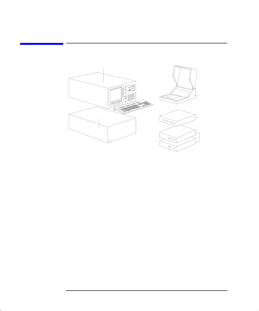
• Agilent 41501A/B SMU/Pulse Generator Expander
The 41501A/B SMU and Pulse Generator Expander contains pulse generator
units (PGUs) and additional SMUs. The 41501A/B is attached to and controlled
by the 4155B/4156B.
• Test Fixture
Agilent 16442A is the test fixture for the 4155B/4156B. You can mount your
device under test (DUT) on the 16442A, and measure the device characteristics.
• Resistor Box
Agilent 16441A R-Box contains accurate 10 kW, 100 kW, and 1 MW resistors,
and connection of these resistors is controlled by the 4155B/4156B. The 16441A
is used to measure negative resistance and to prevent DUT damage when
performing breakdown measurements.
1-4 Agilent 4155B/4156B User’s Guide Vol.1, Edition 4

Introducing the 4155B/4156B
Overview
• SMU/PGU Selector
Agilent 16440A SMU/Pulse Generator Selector contains two switching circuits
to connect the DUT to either an SMU or PGU. You can attach another 16440A
to add two more switching circuits.
Agilent 4155B/4156B User’s Guide Vol.1, Edition 4 1-5

Introducing the 4155B/4156B
Measurement Unit Configurations
Measurement Unit Configurations
Agilent 4155B, 4156B, and 41501A/B are frames that contain the measurement
units. The measurement units are installed before the product is shipped from
factory. User cannot reconfigure the installed units.
• Agilent 4155B configuration:
• four medium power source monitor units (MPSMUs).
• two voltage source units (VSUs).
• two voltage monitor units (VMUs).
• Agilent 4156B configuration:
• four high resolution source monitor units (HRSMUs).
• two voltage source units (VSUs).
• two voltage monitor units (VMUs).
The 4156B has higher measurement resolution. For details about measurement
range and resolution, refer to "Measurement Units" in the 4155B/4156B User's
Guide: Measurement and Analysis.
• Agilent 41501A/B configuration:
The 41501A/B is attached to the 4155B/4156B at your site. See Chapter 2,
“Installation,” on how to install the 41501A/B.
The 41501A/B contains a ground unit (GNDU). In addition, you specify an
option number according to desired units as follows:
Table 1-1 Configuration of the 41501A/B
Unit
One GNDU yes yes yes yes yes
Two PGUs yes yes yes
Two MPSMUs yes yes
One HPSMU
a. HPSMU: high power source monitor unit
1-6 Agilent 4155B/4156B User’s Guide Vol.1, Edition 4
a
Agilent 41501A/B Option
402 410 412 420 422
yes yes
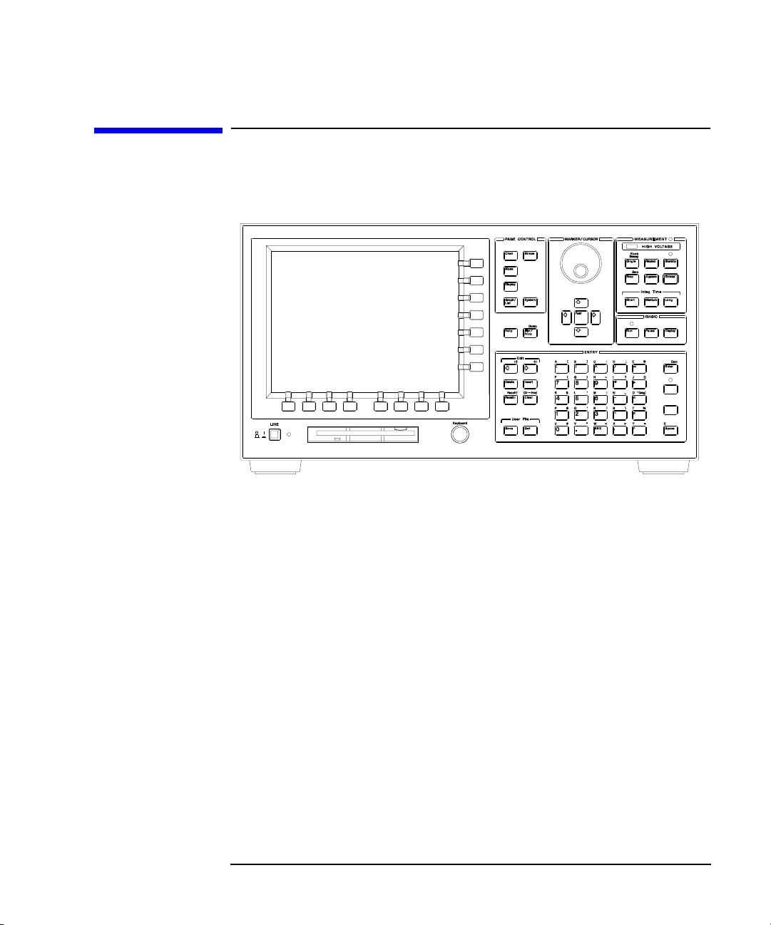
Front View of the 4155B/4156B
Figure 1-1 Front View of the 4155B/4156B
Introducing the 4155B/4156B
Front View of the 4155B/4156B
• LINE switch
Use the LINE switch to turn analyzer on and off.
• Flexible disk drive (FDD)
Use 3.5 inch diskette to load or store the analyzer settings and measurement
data.
• Keyboard connector
You can use an IBM PC/AT compatible keyboard to operate the 4155B/4156B.
See Chapter 6, “External Keyboard.”
• Help key
Pressing Help key displays the help screens.
• Plot/Print key
Pressing Print/Plot key prints the setup information and measurement results to
your plotter, printer, or file, TIFF, PCL, or HP-GL file.
If you press green key and Print/Plot key, the screen image is dumped to plotter,
printer, or file.
Agilent 4155B/4156B User’s Guide Vol.1, Edition 4 1-7

Introducing the 4155B/4156B
Front View of the 4155B/4156B
• PAGE CONTROL key group
Page Control keys are used to change the display screens.
Chan key Moves to CHANNELS screen group. You define channels,
user functions, and user variables.
Meas key Moves to MEASURE screen group. You set the output
parameters, measurement parameters, and so on.
Display key Moves to DISPLAY screen group. You set the result display
format, auto analysis definitions, and so on.
Graph/List key Moves to GRAPH/LIST screen group. This softkey toggles
between GRAPH and LIST screens.
Stress key Moves to STRESS screen group. You define the stress
channels, set the stress parameters, and monitor the stress
forcing.
System key Moves to SYSTEM screen group. You operate on diskette
files, set up plotting and printing environment, define colors
of the display, and so on.
• MARKER/CURSOR key group
Rotary knob and arrow keys of the Marker/Cursor key group are used to move
the marker and cursor.
Rotary knob Moves the marker, or increases or decreases setup value.
Arrow keys Up, Down, Left, and Right. Moves field pointer or cursor.
Fast key Moves the marker or cursor faster. When you rotate the
rotary knob or press the arrow keys with holding Fast key
down, the marker or cursor moves faster.
1-8 Agilent 4155B/4156B User’s Guide Vol.1, Edition 4

Introducing the 4155B/4156B
Front View of the 4155B/4156B
• MEASUREMENT key group
Measurement keys control the measurement, stress, and integration time.
Single key Executes the measurement once, then returns to the idle
state (or standby state if standby is enabled for the channel)
after the measurement is finished. Measurement data is
updated, so data of previous measurement is lost. Pressing
the green key, then Single key starts knob sweep
measurement.
Repeat key Starts and repeats the measurement continuously.
Measurement data is updated, so data of previous
measurement is lost. To stop the measurement, press Stop
key.
Append key Executes the measurement once, then returns to idle state
(or standby state if standby is enabled for the channel) after
measurement is finished. Measurement data is appended to
data of previous measurement.
Stop key Stops the measurement or stress. Standby enabled channels
return to standby state, and other channels return to idle
state.
Standby key Toggles between the standby enabled (Standby indicator is
lit) and disabled states. If Standby indicator is lit, then
STBY ON channels change to standby state (instead of idle
state) when measurement or stress finishes. Stop key has no
affect on standby state.
Stress key Forces the specified stress. The guide around this key
prevents you from accidently pressing the Stress key.
Short,
Medium, and
Long keys Sets the integration time to SHORT, MEDIUM, or LONG,
respectively.
• MEASUREMENT indicator
This indicator lights when the 4155B/4156B is in the measurement state.
• HIGH VOLTAGE indicator
This indicator lights when a unit forces more than 40 V.
Agilent 4155B/4156B User’s Guide Vol.1, Edition 4 1-9

Introducing the 4155B/4156B
Front View of the 4155B/4156B
• Standby indicator
This indicator lights when the 4155B/4156B is standby enabled, which means
that the channels that are standby enabled (STBY ON) will return to the standby
state after the measurement is finished.
• IBASIC key group
IBASIC keys control the IBASIC program execution.
Run key Starts the IBASIC program that is in memory. The indicator
is on during program execution.
Pause key Pauses the IBASIC program execution.
Display key Toggles between the IBASIC screen and measurement
screen.
• Run indicator
When an IBASIC program is running, this indicator lights.
• ENTRY key group
You enter or modify data such as output values, comments, and variable names.
Character keys Are used to enter alphanumeric and special characters.
Enter key After you enter desired characters into the data entry field,
press this key. The characters are entered at the field pointer
location. Also, you can use the green key to calculate the
value of the data entry field. For example, if you press 4 * 6
green key and Enter key, the result (24) appears.
Blue key Changes entry mode to blue-key shift mode, and lights the
indicator. In this mode, you can enter the blue characters
that are printed above the keys. Pressing blue key again
changes to normal mode. Indicator turns off.
Green key Changes entry mode to green-key shift mode. This mode is
effective for the next pressed key, then changes back to
normal mode.
Edit keys Are used to edit the characters in the data entry field.
User File keys Are used to operate quickly on a file in diskette, internal
memory or a directory on a NFS server. Pressing Save key
moves into the filer's SAVE function, and pressing Get key
moves into the filer's GET function.
1-10 Agilent 4155B/4156B User’s Guide Vol.1, Edition 4

Rear View of the 4155B/4156B
Figure 1-2 Rear View of the 4155B/4156B
Introducing the 4155B/4156B
Rear View of the 4155B/4156B
Agilent 4155B/4156B User’s Guide Vol.1, Edition 4 1-11

Introducing the 4155B/4156B
Rear View of the 4155B/4156B
• To R-Box terminal
"To R-Box" terminal is a 10-pin connector. To use R-Box, connect this terminal
to control terminal of Agilent 16441A R-Box.
• VSU terminals
VSU output terminals are BNC connectors. To use VSUs, connect these
terminals to VSU terminals of Agilent 16442A or connector plate.
• VMU terminals
VMU input terminals are BNC connectors. To use VMUs, connect these
terminals to VMU terminals of the 16442A or connector plate.
• SMU terminals
The 4155B has four triaxial connectors. The 4156B has eight triaxial connectors,
and you can use Kelvin connections. When you use the 16442A test fixture and
Kelvin connections, up to 3 SMUs can be connected to the 16442A test fixture.
• Circuit Common ( ) and Frame ground ( ) terminals
For floating measurement, remove the shorting bar (Agilent part number
5000-4206).
WARNING Do not float the Circuit Common terminal at voltages greater than ±42 V
referenced to frame ground. Failure to heed this warning may result in damage
to Agilent 4155B/4156B.
• To Expander Box Interface
When you use Agilent 41501A/B, you insert the board for the 41501A/B into
this interface.
• Zero Check terminal
Ground reference point of the 4155B/4156B.
• Serial number
You need this serial number when using the telephone assistance program
(Agilent Technologies HelpLine).
1-12 Agilent 4155B/4156B User’s Guide Vol.1, Edition 4

Introducing the 4155B/4156B
Rear View of the 4155B/4156B
• Intlk terminal
Used in conjunction with interlock function of the 4155B/4156B. If the Intlk
terminal is open, maximum SMU output is limited to 40 V. Be sure to connect
this terminal to the 16442A test fixture or connector plate before performing
measurement. If you use connector plate, you must install interlock circuit. For
details on how to install the interlock circuit, see “To Make an Interlock Circuit”
in Chapter 2.
WARNING Dangerous voltage of up to the maximum voltage of SMUs may be present at
force, guard, and sense terminals if the interlock terminal is shorted.
• LAN interface
RJ45 connector. Ethernet IEEE 802.3 10BASE-T for a 10M bps CSMA/CD
local area network.
The 4155B/4156B can be a NFS cluster, and can use a remote printer to make
hardcopies.
• Parallel interface
25-pin parallel I/O interface port for connecting peripheral such as a Centronics
parallel printer.
• GPIB interface
Use Agilent 10833A/B/C/D GPIB cable.
• Ext Trig terminals
Two BNC connectors: one for trigger input, and one for trigger output.
• LINE input receptacle
AC power cable is connected to this receptacle.
Agilent 4155B/4156B User’s Guide Vol.1, Edition 4 1-13

Introducing the 4155B/4156B
Front and Rear View of the 41501A/B
Front and Rear View of the 41501A/B
Figure 1-3 Front and Rear View of the 41501A
1-14 Agilent 4155B/4156B User’s Guide Vol.1, Edition 4

Introducing the 4155B/4156B
Front and Rear View of the 41501A/B
• LINE switch
Use the LINE switch to turn the 41501A/B on and off. You must turn on the
41501A/B before turning on the 4155B/4156B.
• Fuse (only for 41501A)
Use the following fuse:
Line Fuse type Agilent part number
100/120 Vac UL/CSA T 8A, 250 Vac 2110-0383
220/240 Vac UL/CSA T 4A, 250 Vac 2110-0014
• Voltage Selector (only for 41501A)
Voltage selector must be in proper position. Line voltage and position are:
Line Voltage Position
90 — 132 Vac left
198 — 264 Vac right
• LINE input receptacle
AC power cable is connected to this receptacle.
• Serial number
The 41501A/B has its own serial number. You need this serial number when
using the telephone assistance program (Agilent Technologies HelpLine).
• GNDU connector
The GNDU connector is a triaxial connector: inner conductor is sense, middle
conductor is force, and outer conductor is circuit common.
Agilent 4155B/4156B User’s Guide Vol.1, Edition 4 1-15

Introducing the 4155B/4156B
Front and Rear View of the 41501A/B
Option 402
The 41501A/B Option 402 has two PGUs.
Figure 1-4 Rear View of the 41501A/B Option 402
• PGU output terminals
BNC connectors. Inner conductor is force and outer conductor is circuit
common.
• Ext Pulse Generator Trig Out terminal
Trigger pulses synchronized with PGU pulses are output. This trigger is used to
synchronize the PGU pulse outputs with external pulse generators. You cannot
change the parameters of this trigger. For details about PGU trigger, see
"Measurement Functions" in the 4155B/4156B User's Guide: Measurement and
Analysis.
• To SMU/Pulse Generator Selector Interface
D-SUB 15-pin connector is used to control the 16440A SMU/pulse generator
selector.
1-16 Agilent 4155B/4156B User’s Guide Vol.1, Edition 4

Option 410
The 41501A/B Option 410 has one HPSMU.
Figure 1-5 Rear View of the 41501A/B Option 410
Introducing the 4155B/4156B
Front and Rear View of the 41501A/B
• HPSMU terminals
There are two triaxial connectors for Kelvin connections: one is for force and the
other is for sense. For SMU5.
Agilent 4155B/4156B User’s Guide Vol.1, Edition 4 1-17

Introducing the 4155B/4156B
Front and Rear View of the 41501A/B
Option 412
The 41501A/B Option 412 has one HPSMU and two PGUs.
Figure 1-6 Rear View of the 41501A/B Option 412
• HPSMU terminals
There are two triaxial connectors for Kelvin connections: one is for force and the
other is for sense. For SMU5.
• PGU output terminals
BNC connectors. Inner conductor is force and outer conductor is circuit
common.
• Ext Pulse Generator Trig Out terminal
Trigger pulses synchronized with PGU pulses are output. This trigger is used to
synchronize the PGU pulse outputs with external pulse generators. You cannot
change the parameters of this trigger. For details about PGU trigger, see
"Measurement Functions" in the 4155B/4156B User's Guide: Measurement and
Analysis.
• To SMU/Pulse Generator Selector Interface
D-SUB 15-pin connector is used to control the 16440A SMU/pulse generator
selector.
1-18 Agilent 4155B/4156B User’s Guide Vol.1, Edition 4

Option 420
The 41501A/B Option 420 has two MPSMUs.
Figure 1-7 Rear View of the 41501A/B Option 420
Introducing the 4155B/4156B
Front and Rear View of the 41501A/B
• MPSMU terminals
Two MPSMUs are installed and each MPSMU has a triaxial connector. These
connectors are not designed for Kelvin connections. For SMU5 and SMU6.
Agilent 4155B/4156B User’s Guide Vol.1, Edition 4 1-19

Introducing the 4155B/4156B
Front and Rear View of the 41501A/B
Option 422
The 41501A/B Option 422 has two MPSMUs and two PGUs.
Figure 1-8 Rear View of the 41501A/B Option 422
• MPSMU terminals
Two MPSMUs are installed and each MPSMU has a triaxial connector. These
connectors are not designed for Kelvin connections. For SMU5 and SMU6.
• PGU output terminals
BNC connectors. Inner conductor is force and outer conductor is circuit
common.
• Ext Pulse Generator Trig Out terminal
Trigger pulses synchronized with PGU pulses are output. This trigger is used to
synchronize the PGU pulse outputs with external pulse generators. You cannot
change the parameters of this trigger. For details about PGU trigger, see
"Measurement Functions" in the 4155B/4156B User's Guide: Measurement and
Analysis.
• To SMU/Pulse Generator Selector Interface
D-SUB 15-pin connector is used to control the 16440A SMU/pulse generator
selector.
1-20 Agilent 4155B/4156B User’s Guide Vol.1, Edition 4

2 Installation
Agilent 4155B/4156B User’s Guide Vol.1, Edition 4

Installation
This chapter describes the requirements and procedures to install Agilent
4155B/4156B. It contains the following information:
• requirements
• inspection
• connecting the 41501A/B
• installing accessories
• mounting connectors
• connecting peripherals
WARNING There are potentially hazardous voltages (200 V for HPSMU, and 100 V for
HRSMU and MPSMU) present at the Force, Guard, and Sense terminals of the
4155B/4156B. To prevent electrical shock, the following safety precautions
must be observed during the use of the 4155B/4156B.
• Use a three-conductor ac power cable to connect the cabinet (if used) and
the 4155B/4156B to an electrical ground (safety ground).
• If you do not use the 16442A test fixture, you must connect the Intlk
terminal to a switch that turns off when the shielding box access door is
opened.
• Confirm periodically that the interlock function works normally.
• Before touching the connections on the Force, Guard, and Sense
terminals, turn the 4155B/4156B off and discharge any capacitors. If you
do not turn the 4155B/4156B off, complete all of the following items,
regardless of the 4155B/4156B settings.
• Terminate measurement by pressing Stop key, confirm that the
MEASUREMENT indicator is not lit.
• Deactivate standby mode (if used) by pressing Standby key, confirm
that the Standby indicator is not lit.
• Confirm that the HIGH VOLTAGE indicator is not lit.
• Open the shielding box access door (open the Intlk terminal).
• Discharge any capacitors connected to an SMU.
• Warn persons working around the 4155B/4156B about dangerous
conditions.
2-2 Agilent 4155B/4156B User’s Guide Vol.1, Edition 4

Installation
Requirements
Requirements
This section contains information on:
• power requirements
• power cables
• line fuse and line voltage selectors (for the 41501A)
• ventilation requirements
• operating environment
• storaging/shipping environment
• cleaning
Power Requirements
The 4155B/4156B can operate from any single-phase ac power source supplying 90
to 264 V at 47 to 63 Hz. The maximum power consumption is 450 VA for the
4155B/4156B/41501A, and 350 VA for the 41501B. For details, see Chapter 8.
Power Cable
CAUTION Before applying ac line power to the 4155B/4156B or the 41501A/B, ensure that the
correct power cable is used.
In accordance with international safety standards, this instrument is equipped with a
three-prong power cable. When connected to an appropriate ac power outlet, this
cable grounds the instrument frame. The type of power cable shipped with each
instrument depends on the country of destination. Refer to the following table for
the Agilent part numbers of the power cables available.
If the plug on the cable does not fit the power outlet, or the cable is to be attached to
a terminal block, cut the cable at the plug end and re-wire it. This work should be
performed by a qualified electrician, observing all local electrical codes.
The color coding used in the cable will depend on the cable supplied. If a new plug
is to be connected, it must meet local safety requirements and include the following
features:
• adequate load-carrying capacity (see Chapter 8)
• ground connection
• cable clamp
Agilent 4155B/4156B User’s Guide Vol.1, Edition 4 2-3

Installation
Requirements
WARNING For protection from electrical shock, do not interrupt the power cable ground.
• Plug: BS 1363/A,
250 V, 10 A
• Cable: 8120-1351
• Plug: NEMA 5-15P,
125 V, 10 A
• Cable: 8120-1378
• Plug: SR 107-2-D,
250 V, 10 A
• Cable: 8120-2956
• Plug: AS 3112, 250 V,
10 A
• Cable: 8120-1369
• Plug: NEMA 6-15P,
250 V, 6 A
• Cable: 8120-0698
• Plug: IEC 83-B1,
250 V, 10 A
• Cable: 8120-4211
• Plug: CEE 7 Standard
Sheet VII, 250 V, 10 A
• Cable: 8120-1689
• Plug: SEV Type 12,
250 V, 10 A
• Cable: 8120-2104
• Plug: JIS C 8303,
125 V, 12 A
• Cable: 8120-4753
• Plug: Argentine
Resolution 63, Annex
IV, 250 V, 10 A
• Cable: 8120-6870
• Plug: CEI 23-16, 250 V,
10 A
• Cable: 8120-6978
• Plug: GB 1002, 250 V,
10 A
• Cable: 8120-8376
2-4 Agilent 4155B/4156B User’s Guide Vol.1, Edition 4

Installation
Requirements
Line Fuse and Line Voltage Selector for the 41501A
Before applying ac line power to the 41501A, verify that the correct line fuse is
installed in the fuse holder and the line voltage selector is set correctly.
Line Fuse Type Agilent Part Number
100/120 Vac UL/CSA T 8A, 250 Vac 2110-0383
220/240 Vac UL/CSA T 4A, 250 Vac 2110-0014
WARNING Replace the line fuse only with the same type and rating. Do not use repaired
fuses, and do not short circuit the fuse holder.
The line voltage selector switch is set at the factory. Verify the voltage selector
setting before applying ac line power to the 41501A. The line voltage selector
switch is located on the rear panel of the 41501A
Line Voltage Position
90 — 132 Vac left
198 — 264 Vac right
Ventilation Requirements
The 4155B/4156B has one cooling fan, and the 41501A/B has two cooling fans. To
ensure adequate airflow, make sure that there is sufficient clearance around the
cooling fans: 6 inches (150 mm) behind, 3 inches (70 mm) on the sides, and 0.5 inch
(12 mm) above and below.
If the airflow is restricted, the internal operating temperature will be higher. This
may reduce the instrument's reliability, or cause the thermal-protection circuits to
turn the instrument off.
Agilent 4155B/4156B User’s Guide Vol.1, Edition 4 2-5

Installation
Requirements
Operating Environment
The 4155B/4156B and the 41501A/B are specified to operate within the following
environmental conditions:
Temperature: 10 °C to 40 °C (with using flexible disk drive) 5 °C to 40 °C
(without using flexible disk drive)
Humidity: 20 % to 80 % RH (with using flexible disk drive)
15 % to 80 % RH (without using flexible disk drive)
non-condensing and wet bulb temperature £ 29 °C
Altitude: 0 to 2000 m
Storaging/Shipping Environment
The 4155B/4156B and the 41501A/B are specified to store/ship within the
following environmental conditions:
Temperature: -22 °C to 60 °C
Humidity: 5 % to 90 % RH, non-condensing and wet bulb temperature
£ 39 °C
Altitude: 0 to 4600 m
Cleaning
To prevent electrical shock, disconnect the 4155B/4156B and 41501A/B from mains
before cleaning. Use a dry cloth to clean the external case parts.
2-6 Agilent 4155B/4156B User’s Guide Vol.1, Edition 4

Installation
Inspection
Inspection
This section describes what to do when you receive the 4155B/4156B and
accessories.
1. Inspect the shipment.
2. Verify the 4155B/4156B operation.
To maintain the 4155B/4156B and 41501A/B measurement accuracy specifications,
perform calibration and adjustments once a year.
To Inspect the 4155B/4156B and Accessories
Perform the following inspections when the 4155B/4156B and accessories arrive at
your site.
• Before unpacking any components, inspect all boxes for any signs of damage
that might have occurred during shipment, such as:
• dents
• scratches
• cuts
• water marks
If you suspect any damage, notify your local Agilent Technologies sales or
service office.
• When you open the boxes that contain the 4155B/4156B and accessories, check
the components against the contents lists attached to the boxes.
If anything is missing, notify your local Agilent Technologies sales or service
office.
Agilent 4155B/4156B User’s Guide Vol.1, Edition 4 2-7

Installation
Inspection
To Check the 4155B/4156B Operation
1. Make sure that the line switches are set to off.
2. If the 41501A/B will be used with the 4155B/4156B, connect the 41501A/B as
shown in “Connecting the 41501A/B SMU/Pulse Generator Expander” on page
2-11.
3. On the 4155B/4156B, make sure that the Circuit Common terminal is connected
to the frame ground terminal by a shorting-bar.
WARNING If the Circuit Common terminal is not connected to the frame ground terminal,
a potential shock hazard exists.
4. Connect the power cable from the 4155B/4156B to an ac power outlet. If the
41501A/B will be used, connect the power cable from the 41501A/B to the
outlet.
5. If the 41501A/B is installed, press the LINE button to turn the instrument on.
6. Press the LINE button to turn the 4155B/4156B on. The initialization screen will
appear on the display of the instrument.
7. After the initialization is finished, the CHANNELS: CHANNEL DEFINITION
screen will appear as shown in the figure below.
2-8 Agilent 4155B/4156B User’s Guide Vol.1, Edition 4

Installation
Inspection
8. Make sure that the units displayed in the UNIT column match the units installed.
The following table shows the displayed units in the UNIT column:
4155B 4156B Additional Units by Using 41501A/B Expander
SMU1:MP
SMU2:MP
SMU3:MP
SMU4:MP
VSU1
VSU2
VMU1
VMU2
SMU1:HR
SMU2:HR
SMU3:HR
SMU4:HR
VSU1
VSU2
VMU1
VMU2
(Opt. 402)
PGU1
PGU2
GNDU
(Opt. 410)
SMU5:HP
GNDU
(Opt. 412)
SMU5:HP
PGU1
PGU2
GNDU
(Opt. 420)
SMU5:MP
SMU6:MP
GNDU
9. If the 41501A/B units are not displayed in the UNIT column, turn off the
4155B/4156B and the 41501A/B. Make sure that the 41501A/B interface board
is firmly inserted into the 4155B/4156B. Turn on the 41501A/B, then turn on the
4155B/4156B.
10. Press the System key on the front panel, then select MISCELLANEOUS
softkey. Confirm that the POWER LINE FREQUENCY is correct for your site.
If not, select the correct softkey.
When you turn on the 4155B/4156B, the unit will execute a power-on self-test. If no
error message is displayed on the screen, the 4155B/4156B is operating correctly.
If a problem occurs, see Chapter 10.
(Opt. 422)
SMU5:MP
SMU6:MP
PGU1
PGU2
GNDU
Agilent 4155B/4156B User’s Guide Vol.1, Edition 4 2-9

Installation
Inspection
To Execute Diagnostics and Calibration
You can execute diagnostics and/or calibration to verify the operation of the
4155B/4156B.
1. Press System key, then CALIB/DIAG softkey.
The SYSTEM: SELF-CALIBRATION/DIAGNOSTICS screen is displayed.
2. Disconnect all cables from the measurement terminals on the 4155B/4156B rear
panel.
3. If you want to execute both diagnostics and calibration, select DIAG SELFTST
ALL softkey.
4. If you want to execute calibration only, select CALIB ALL softkey.
5. To stop the diagnostics or calibration, select STOP softkey.
2-10 Agilent 4155B/4156B User’s Guide Vol.1, Edition 4

Installation
Connecting the 41501A/B SMU/Pulse Generator Expander
Connecting the 41501A/B SMU/Pulse Generator
Expander
1. Place the 41501A/B on your workbench. 2. Place the 4155B/4156B on top of the
41501A/B.
3. Remove the blank panel labeled "To
Expander Box Interface" from the rear
panel of the 4155B/4156B.
WARNING The 4155B/4156B, together with the 41501A/B, weights about 37 kg (81.8 lb).
The 4155B/4156B is not anchored to the 41501A/B. Use caution when handling.
Agilent 4155B/4156B User’s Guide Vol.1, Edition 4 2-11
4. Insert the 41501A/B interface board into
the 4155B/4156B, then attach it with the
thumbscrews.

Installation
Installing Accessories
Installing Accessories
This section describes how to install the 4155B/4156B and accessories. Additional
information regarding airflow can be found in the “Ventilation Requirements” on
page 2-5.
This section describes how to:
• install the 16442A test fixture
• install the 16441A R-box
• install the 16440A SMU/pulse generator selector
• connect the 16440A to the 4155B/4156B
• connect a measurement cable to a connector plate
When you install a keyboard, connect the keyboard to the keyboard interface on the
front-panel before switching on the 4155B/4156B. The 4155B/4156B recognizes
the keyboard during the power-on self-test.
2-12 Agilent 4155B/4156B User’s Guide Vol.1, Edition 4

Installation
Installing Accessories
To Install the 16442A Test Fixture
Before performing this procedure, turn off the 4155B/4156B and 41501A/B.
When you use the 16442A test fixture without the 16441A R-box or the 16440A
selector, you can stabilize the 16442A as shown in the figure below.
1. Put a stabilizer on both sides of the test fixture.
2. Attach each stabilizer to the unit with a flathead screw.
Agilent 4155B/4156B User’s Guide Vol.1, Edition 4 2-13

Installation
Installing Accessories
Connecting the 4155B and the 16442A test fixture
Connect the 4155B and the 16442A as shown below.
CAUTION To prevent electrical shock during use, be sure to connect the interlock cable.
16442A
4. MPSMUs
2. VSUs
Cable
4155B Terminals
3. VMUs
1. Intlk
4155B
16442A
Terminals
Intlk Intlk 3 m or 1.5 m Interlock Cable
VSU VSU 3 m or 1.5 m Coaxial Cable
VMU VMU 3 m or 1.5 m Coaxial Cable
MPSMU SMU 3 m or 1.5 m Triaxial Cable
WARNING There are potentially hazardous voltages of up to ±100 V at the Force and
Guard terminals. To prevent electrical shock, do not expose these lines.
CAUTION Never connect the Guard terminal to any output, including circuit common, frame
ground, or any other guard terminal. Doing so will damage the SMU.
2-14 Agilent 4155B/4156B User’s Guide Vol.1, Edition 4

Installation
Installing Accessories
Connecting the 4156B and the 16442A test fixture
Connect the 4156B and the 16442A as shown below.
CAUTION To prevent electrical shock during use, be sure to connect the interlock cable.
16442A
4. HRSMUs
2. VSUs3. VMUs
1. Intlk
4156B
4156B Terminals
16442A
Terminals
Cable
Intlk Intlk 3 m or 1.5 m Interlock Cable
VSU VSU 3 m or 1.5 m Coaxial Cable
VMU VMU 3 m or 1.5 m Coaxial Cable
HRSMU SMU1 and SMU2 3 m or 1.5 m Kelvin Triaxial Cable
SMU3 and SMU4
SMU5 and SMU6
WARNING There are potentially hazardous voltages of up to ±100 V at the Force, Sense,
and Guard terminals. To prevent electrical shock, do not expose these lines.
CAUTION Never connect the Guard terminal to any output, including circuit common, chassis
ground, or any other guard terminal. Doing so will damage the SMU.
Agilent 4155B/4156B User’s Guide Vol.1, Edition 4 2-15

Installation
Installing Accessories
Connect the 41501A/B measurement terminals to the 16442A input as follows:
41501A/B
Terminals
GNDU GNDU 3 m or 1.5 m GNDU Cable
PGU PGU 3 m or 1.5 m Coaxial Cable
MPSMU SMU 3 m or 1.5 m Triaxial Cable
HPSMU SMU1 and SMU2 3 m or 1.5 m Kelvin Triaxial Cable
WARNING Use Agilent 16493H GNDU cable to connect the GNDU to a test fixture or a
connector plate. Do not use the triaxial cable. The GNDU cable is rated for up
to 1.6 A, but the maximum current rating of the triaxial cable is 1 A.
WARNING There are potentially hazardous voltages of up to ±200 V at the Force, Sense,
and Guard terminals. To prevent electrical shock, do not expose these lines.
CAUTION Never connect the Guard terminal to any output, including circuit common, chassis
ground, or any other guard terminal. Doing so will damage the SMU.
16442A
Terminals
SMU3 and SMU4
SMU5 and SMU6
Cable
2-16 Agilent 4155B/4156B User’s Guide Vol.1, Edition 4

Installation
Installing Accessories
Installing the 16442A test fixture with other accessories
The 16442A test fixture can be installed with an 16441A R-box, 16440A selector, or
both. The following figure shows how to attach the 16442A to other accessories.
Agilent 4155B/4156B User’s Guide Vol.1, Edition 4 2-17

Installation
Installing Accessories
To Install the 16441A R-Box
Before installing the 16441A R-box, turn off the 4155B/4156B and 41501A/B.
1. Connect the To R-Box terminal on the 4155B/4156B to the Control terminal on
the 16441A rear panel using a 3.0 m or 1.5 m control cable.
2. Connect the instrument measurement terminals to the 16441A input terminals as
follows:
Instrument
terminals
16441A Input Cable
4155B MPSMU Input Force 3 m or 1.5 m Triaxial Cable
4156B HRSMU Input
3 m or 1.5 m Kelvin Triaxial Cable
(Force/Sense)
41501A/B MPSMU Input Force 3 m or 1.5 m Triaxial Cable
41501A/B HPSMU Input
3 m or 1.5 m Kelvin Triaxial Cable
(Force/Sense)
3. Connect the 16441A output terminals to the 16442A input terminals, or to the
connector plate input terminals, using 40 cm triaxial cables as shown below:
16441A Output 16442A Input or Connector Plate Input
Output Force
Output Force
Output Sense
a
b
b
SMU1, 2, 3, 4, 5, or 6
SMU1 SMU3 SMU5
SMU2 SMU4 SMU6
a. For non-Kelvin connection.
b. For the Kelvin connection, two triaxial cables must be used to con-
nect the 16441A and the 16442A, instead of a Kelvin triaxial cable.
Installing the 16441A R-box with other accessories
You can attach the 16441A R-box to the 16442A test fixture or to your shielding
box, as shown in the following figures.
2-18 Agilent 4155B/4156B User’s Guide Vol.1, Edition 4

Attaching the 16441A R-Box to the 16442A Test Fixture
Attaching the 16441A R-Box to the Shielding Box
Installation
Installing Accessories
Agilent 4155B/4156B User’s Guide Vol.1, Edition 4 2-19

Installation
Installing Accessories
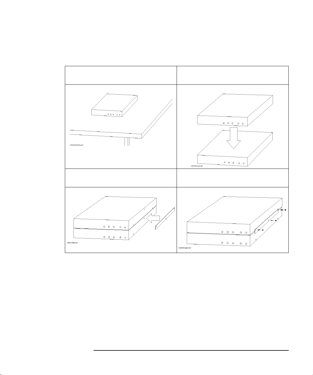
To Install the 16440A SMU/Pulse Generator Selector
To use the 16440A, the 4155B/4156B must be equipped with an 41501A/B
SMU/pulse generator expander with two PGUs.
• To attach the 16440A selector to the 16442A test fixture:
1. Place the 16440A selector on your
workbench.
3. Position a plate on both sides. 4. Attach each plate using the three flathead
2. Place the 16442A test fixture on top of the
16440A selector.
screws supplied with the instrument.
2-20 Agilent 4155B/4156B User’s Guide Vol.1, Edition 4

Installation
Installing Accessories
• The following steps apply when using two 16440A SMU/pulse generator
selectors:
5. Place the second 16440A on your
workbench. Place the 16440A selector and
the 16442A test fixture on top of the
second 16440A.
6. Position a plate on both sides. 7. Attach each plate using the three flathead
screws supplied with the instrument.
Agilent 4155B/4156B User’s Guide Vol.1, Edition 4 2-21

Installation
Installing Accessories
• To attach an 16441A R-box to the 16442A test fixture and the 16440A selector:
• To attach the 16440A selector to a shielding box:
The figure above shows the spacing of the 16440A screw holes. You need to prepare four
screws and nuts to match the screw holes.
2-22 Agilent 4155B/4156B User’s Guide Vol.1, Edition 4
Installation
Installing Accessories
• If you use two 16440As, connect the 16440As before connecting to the shielding
box, as shown below:
1. Place the 16440A on your workbench. 2. Place the second 16440A on top of the
16440A.
3. Position a plate on both sides. 4. Attach each plate using the three flathead
screws supplied with the instrument.
Agilent 4155B/4156B User’s Guide Vol.1, Edition 4 2-23

Installation
Installing Accessories
• To connect the selector to the shielding box:
1. Attach an angle bracket to each side of the 16440A, using the screws supplied.
2. Place the 16440A(s) on the side panel of
the shielding box.
3. Position four nuts on the inside panel of
the shielding box.
4. Attach the angle bracket to the shielding
box using four flathead screws.
2-24 Agilent 4155B/4156B User’s Guide Vol.1, Edition 4

Installation
Installing Accessories
• To attach an 16441A R-box to the 16440A selector on the shielding box:
Agilent 4155B/4156B User’s Guide Vol.1, Edition 4 2-25

Installation
Installing Accessories
To Connect the 16440A Selector to the 4155B/4156B
• Connecting two 16440A selectors
If you use two 16440A, connect the Control Output terminal of the selector to
the Control Input terminal of the second selector using a 40 cm control cable as
shown below.
2-26 Agilent 4155B/4156B User’s Guide Vol.1, Edition 4

Installing Accessories
• Connecting the 16440A selector to the 4155B/4156B
Turn off the 4155B/4156B and 41501A/B before connecting the instruments.
Then connect as shown below.
4155/4156
16442A Test Fixture
4
2
41501
16440A Selector
3
1
Installation
Instrument Terminal
41501A/B To SMU/Pulse
16440A
Te rm i na l
Cable
CONTROL Input 3.0 m or 1.5 m Control Cable
Generator Selector
Interface
PGU
Input PGU
a
3.0 m or 1.5 m Coaxial Cable
MPSMU or HPSMU Input SMU 3.0 m or 1.5 m Triaxial Cable
4155B MPSMU
4156B HRSMU
b
16442A SMU
Output Selected
40 cm Triaxial Cable
Connector Plate SMU
a. You can use two inputs for one selector, and four inputs for two selectors.
b. You can use two outputs for one selector and four outputs for two selectors. Selector
output is either one of the PGU outputs or the SMU output.
Agilent 4155B/4156B User’s Guide Vol.1, Edition 4 2-27

Installation
Installing Accessories
To Connect the Measurement Cable to the Connector Plate
This section provides instructions for connecting the measurement cables from the
4155B/4156B to the connector plate. For connector plate installation information,
refer to the 16495 Installation Guide.
The following connector plates are available for the 4155B/4156B:
Agilent 16495H Connector Plate with 6 Triaxial Connectors
Option 001 has 6 triaxial through connectors (female to
female), 6 BNC through connectors (female to female), an Intlk
connector, and a GNDU connector (triaxial through, female to
female). The back of the Intlk connector is designed for
soldering.
Option 002 has 6 triaxial connectors, 6 BNC connectors, an
Intlk connector, and a GNDU connector. The back of each
connector is designed for soldering.
Agilent 16495J Connector Plate with 8 Triaxial Connectors
Option 001 has 8 triaxial through connectors (female to
female), 4 BNC through connectors (female to female), an Intlk
connector, and a GNDU connector (triaxial through, female to
female). The back of the Intlk connector is designed for
soldering.
Option 002 has 8 triaxial connectors, 4 BNC connectors, an
Intlk connector, and a GNDU connector. The back of each
connector is designed for soldering.
2-28 Agilent 4155B/4156B User’s Guide Vol.1, Edition 4

Installation
Installing Accessories
Connecting the measurement cables
Connect the measurement cables as shown below.
Instrument Connector Plate
Cable
Model No. Connector Model No. Connector
4155B Intlk 16495H/J Intlk 16493J Interlock Cable
MPSMU 16495H INPUT 1 to 6 Triaxial Cable
16495J INPUT 1 to 8
VSU 16495H INPUT 7 to 12 BNC cable
16495J INPUT 9 to 12
VMU 16495H INPUT 7 to 12 BNC cable
16495J INPUT 9 to 12
4156B Intlk 16495H/J Intlk 16493J Interlock Cable
HRSMU 16495H INPUT 1 to 6 Triaxial Cable or Kelvin
16495J INPUT 1 to 8
VSU 16495H INPUT 7 to 12 BNC cable
16495J INPUT 9 to 12
VMU 16495H INPUT 7 to 12 BNC cable
16495J INPUT 9 to 12
41501A/B GNDU 16495H/J GNDU 16493H GNDU Cable
HPSMU 16495H INPUT 1 to 6 Triaxial Cable or Kelvin
16495J INPUT 1 to 8
MPSMU 16495H INPUT 1 to 6 Triaxial Cable
16495J INPUT 1 to 8
PGU 16495H INPUT 7 to 12 BNC cable
16495J INPUT 9 to 12
Agilent 4155B/4156B User’s Guide Vol.1, Edition 4 2-29
Triaxial Cable
Triaxial Cable

Installation
Installing Accessories
Connecting the interlock terminal
The 4155B/4156B provides an interlock terminal to prevent you from receiving an
electrical shock from high voltage (more than ±40 V). If the interlock terminal is
open, the 4155B/4156B cannot force high voltage more than ±40 V.
When using the 16495H/16495J connector plate or the 16442A test fixture, connect
the 4155B/4156B Intlk connector to the external interlock connector using the
supplied 16493J interlock cable.
If you use your own connector plate or test fixture, make an interlock circuit as
shown in “To Make an Interlock Circuit” on page 2-33. Then connect the
4155B/4156B Intlk connector to the external interlock connector by using the
supplied 16493J interlock cable.
If you use a connector plate or test fixture that has a BNC coaxial connector as the
interlock connector, connect the BNC interlock connector to the 4155B/4156B
interlock terminal as follows:
• Required Parts:
Model No. Quantity Description
Agilent 16435A 1 Interlock Cable Adapter
Agilent 16493J 1 Interlock Cable (supplied with the
4155B/4156B)
• Procedure:
1. Connect the interlock (Intlk) connector on the 4155B/4156B rear panel to
the interlock cable adapter using the supplied interlock cable.
2. Connect the interlock cable adapter to the connector plate or test fixture
using the supplied coaxial cable.
2-30 Agilent 4155B/4156B User’s Guide Vol.1, Edition 4

Installation
Mounting Connectors
Mounting Connectors
Previous sections described how to install the available accessories, and the 16495
Installation Guide provides the information on how to install connector plates on the
shielding box. However, you may choose to mount connectors directly on your own
connector plate or test fixture.
To do this, you will need to make connector holes and mount the connectors
yourself. This section contains information on connector hole dimensions.
To mount connectors:
1. Select the appropriate parts for your application. See Table 2-1.
2. Make the holes and mount the connectors. See Table 2-2.
For Kelvin connections using the 4156B SMU, use Agilent 16494B Kelvin
cable. A Kelvin cable requires a Kelvin triaxial connector, which has two
connector holes and three screw holes.
3. Build the interlock circuit shown in “To Make an Interlock Circuit” on page
2-33.
4. Attach cables from the connectors to the DUT (device under test). Refer to “To
Connect the GNDU Output”, “To Connect the SMU Output”, and “To Connect
the VSU/VMU/PGU Outputs” later in this chapter.
Table 2-1 lists the parts required to mount connectors on your shielding box. The
type and quantity of parts needed will depend on your application.
Table 2-1 Recommended Parts
Usage Agilent Part No. Description
Making an interlock
circuit
Connecting GNDU to
DUT
Connecting SMU to
DUT
Agilent 4155B/4156B User’s Guide Vol.1, Edition 4 2-31
1252-1419 Interlock Connector (6 pin,
female)
3101-0302 or 3101-3241 Switch
1450-0641 LED (V
8150-4690 Wire
1250-2457 Triaxial Connector (female)
8120-3674 or 8150-2639 Coaxial Cable or Wire
1250-2457 Triaxial Connector (female)
8120-4461 Low Noise Coaxial Cable
@ 2.1 V @ IF = 10 mA)
F

Installation
Mounting Connectors
Usage Agilent Part No. Description
Connecting
VSU/VMU to DUT
Connecting PGU to
DUT
1250-0118 BNC Connector (female)
8150-0447 Wire
1250-0118 BNC Connector (female)
8120-0102 or 8120-4461 Low Noise Coaxial Cable
Table 2-2 Dimensions of Connector Holes
Kelvin Triaxial Connector (in mm) Triaxial Connector (in mm)
BNC Connector (in mm) Interlock Connector (in mm)
2-32 Agilent 4155B/4156B User’s Guide Vol.1, Edition 4

Installation
Mounting Connectors
To Make an Interlock Circuit
The interlock circuit is designed to prevent electrical shock when a user touches the
measurement terminals.
CAUTION You must install an interlock circuit on a shielding box to prevent hazardous
voltages when the door of the shielding box is open.
Figure 2-1 shows the pin assignments of the interlock connector mounted on a
connector plate or test fixture.
Figure 2-1 Interlock Connector Pin Assignments
WARNING Potentially hazardous voltages may be present at the Force, Guard, and Sense
terminals when the interlock terminals are shorted.
Agilent 4155B/4156B User’s Guide Vol.1, Edition 4 2-33

Installation
Mounting Connectors
Installing the interlock circuit
Install the interlock circuit as follows:
1. Mount two mechanical switches on your shielding box, so that the switches
close when the door of the shielding box is closed, and open when the door is
opened. For the dimensions of the switch, see Figure 2-2 and Figure 2-3 below.
2. Mount an LED on your shielding box. For the dimensions of the LED, see
Figure 2-4.
3. Use wire to connect the two switches in series between pin number 1 and 2 (or
3) of the interlock connector. See Figure 2-1.
4. Use wire to connect the LED between pin number 4 and 5 (or 6) of the interlock
connector. See Figure 2-1.
If the 4155B/4156B Intlk connector is connected to the interlock circuit, the
4155B/4156B SMU cannot force more than ±40 V when the door is open. When the
door is closed, it can force more than ±40 V.
When more than ±40 V is forced from an SMU, the LED lights to indicate high
voltage output.
Figure 2-2 Dimensions of the Interlock Switch (Agilent part number 3101-0302)
2-34 Agilent 4155B/4156B User’s Guide Vol.1, Edition 4

Mounting Connectors
Figure 2-3 Dimensions of the Interlock Switch (Agilent part number 3101-3241)
Installation
Figure 2-4 Dimensions of the LED (Agilent part number 1450-0641)
Agilent 4155B/4156B User’s Guide Vol.1, Edition 4 2-35

Installation
Mounting Connectors
NOTE To Perform an Interlock Circuit Test
To confirm that the interlock circuit is operating properly, perform the following
test.
1. Connect the Intlk terminal of the 4155B/4156B to your interlock circuit.
2. Press System key, then select CALIB/DIAG softkey to display the
SYSTEM: SELF-CALIBRATION/DIAGNOSTICS screen.
3. In the CALIB/DIAG field, select DIAG softkey.
4. In the CATEGORY field, select I/O PERIPH softkey.
5. Move the pointer to
403 (INT.) Interlock LED.
6. Select EXECUTE softkey.
7. Confirm the following:
• the LED turns on within 1 second when the interlock circuit is shorted.
• the LED turns off within 1 second when the interlock circuit is opened.
8. To stop the interlock test, select STOP softkey.
2-36 Agilent 4155B/4156B User’s Guide Vol.1, Edition 4

To Connect the GNDU Output
The following figures show connection examples for the GNDU output.
Kelvin connections non-Kelvin connections
Installation
Mounting Connectors
Use a low-noise coaxial cable (Agilent part
number 8120-3674) from the connector to
the prober, socket, or DUT as shown. To
cancel the effects of cable resistance, connect
the Sense line and Force line as close as
possible to the terminal of the DUT.
Insulator
FORCE
SENCE
To
DUT
Plate
Triaxial Connector
Coaxial Cable
Short the Sense and Force on the connector
as shown below. Use AWG 22 single-strand
insulated wire (Agilent part number
8150-2639) from the connector plate to the
prober, socket, or DUT. Measurement results
include the residual resistance of the
connection wire. For a quick connection
where measurement accuracy is not critical,
connect only Force to the DUT, without
shorting the Sense and Force.
Insulator
FORCE
SENCE
To
DUT
Wire
Plate
Triaxial Connector
CAUTION Use Agilent 16493H GNDU cable to connect the GNDU to your connector plate or
test fixture. Do not use the triaxial cable. The GNDU is rated for up to 1.6 A, while
the maximum current rating of the triaxial cable is 1 A.
Agilent 4155B/4156B User’s Guide Vol.1, Edition 4 2-37

Installation
Mounting Connectors
To Connect the SMU Output
The following figures show connection examples for the SMU output.
Kelvin connections non-Kelvin connections
This connection is for the 4156B HRSMU or
the 41501A/B HPSMU. Use low-noise
coaxial cable (Agilent part number
8120-4461) from the connector to the prober,
socket, or DUT as shown. To cancel the
effects of cable resistance, connect the Sense
line and Force line as close as possible to the
DUT terminal. To prevent oscillations, do
not use cables longer than 1.5 m. To make
accurate measurements when applying high
currents, extend the guard as far as possible
from the front panel connector to the DUT.
Physically stabilize the cables with tape.
Insulator
GUARD
FORCE
Triaxial
Connector
Coaxial Cable
To
DUT
The following figure is for the
HRSMU/HPSMU connection using Kelvin
triaxial cable. For the MPSMU connection,
and for the HRSMU/HPSMU connection
using triaxial cable, connect the cable to the
Force terminal only. Use low-noise coaxial
cable (Agilent part number 8120-4461). To
make accurate measurements when applying
high currents, extend the guard as far as
possible from the front panel connector to the
DUT. Measurement results include residual
resistance from the connection cable.
Insulator
GUARD
FORCE
To
DUT
Triaxial
Connector
Coaxial Cable
SENCE
GUARD
Insulator
Plate
GUARD
Insulator
SENCE
Plate
2-38 Agilent 4155B/4156B User’s Guide Vol.1, Edition 4
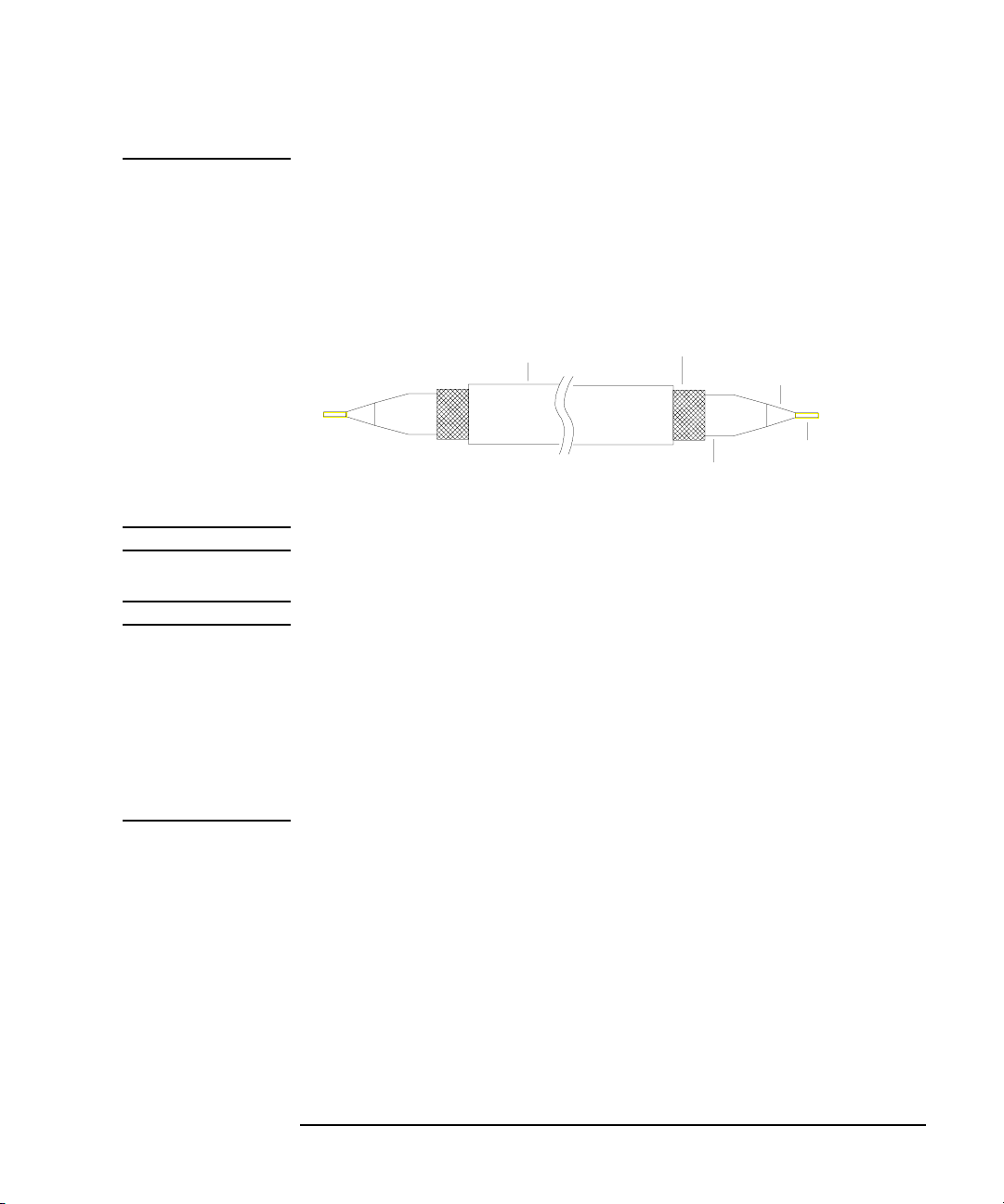
NOTE Low-Noise Coaxial Cable
When you make an SMU output connection by using low-noise coaxial cable
(Agilent part number 8120-4461), trim the conductive layer and the insulator(clear)
so that the center conductor is insulated from the conductive layer. Refer to the
following figure.
Installation
Mounting Connectors
Insulator
(black)
Outer Conductor
for GUARD signal
Conductive Layer
(black)
Insulator (clear)
Center Conductor
for FORCE or SENSE
signal
CAUTION Never connect the Guard terminal to any output, including circuit common, chassis
ground, or any other guard terminal. Doing so will damage the SMU.
WARNING Potentially hazardous voltages, up to ±100 V (±200 V for HPSMU), are present
at the Force, Sense, and Guard terminals.
To prevent electrical shock, do not expose these lines.
Before turning the 4155B/4156B on, connect the Intlk terminal to a switch that
turns off when the shielding box access door is opened.
Before you touch any connections to these terminals, turn the 4155B/4156B off,
disconnect the power cable, and discharge any capacitors.
Agilent 4155B/4156B User’s Guide Vol.1, Edition 4 2-39

Installation
Mounting Connectors
To Connect the VSU/VMU/PGU Outputs
The following figures show connection examples for VSU/VMU and PGU output.
VSU/VMU connector PGU connector
Use AWG 24 single-strand insulated wire
(Agilent part number 8150-0447) to connect
to a prober, socket, or DUT.
COMMON
Insulator
Signal Line
To
DUT
Wire
Plate
BNC Connector
Regardless of the output impedance setting,
use a low-noise coaxial cable (Agilent part
number 8120-0102) from the connector to a
prober, socket, or DUT. If you use an
16440A selector, use a low-noise coaxial
cable (Agilent part number 8120-4461).
COMMON
Insulator
Signal Line
To
DUT
Coaxial Cable
Plate
BNC Connector
2-40 Agilent 4155B/4156B User’s Guide Vol.1, Edition 4

Installation
Connecting Instruments or Peripherals
Connecting Instruments or Peripherals
The 4155B/4156B provides an GPIB interface, parallel I/O interface, and LAN
interface for connection with other instruments or peripherals. This section contains
information required to connect instruments or peripherals.
To Connect GPIB Instruments or Peripherals
The 4155B/4156B has an GPIB interface for instrument, printer, or plotter control.
• If you use an external controller with the 4155B/4156B, connect an GPIB cable
between the controller and the 4155B/4156B.
• If you control instruments using the 4155B/4156B built-in IBASIC capability,
connect an GPIB cable between the instrument and the 4155B/4156B.
• If you use an GPIB printer or plotter to make hard copies, connect an GPIB
cable between the printer or plotter and the 4155B/4156B.
To use the GPIB interface, you will need to fill in the following entry fields on the
SYSTEM: MISCELLANEOUS screen. For details of this setup screen, see
“SYSTEM: MISCELLANEOUS screen” in Chapter 5.
Entry Field Name Description
4155B is
(4156B is) Selects SYSTEM CONTROLLER or NOT SYSTEM
CONTROLLER.
Select NOT SYSTEM CONTROLLER if the 4155B/4156B will
be used with an external controller.
Select SYSTEM CONTROLLER if the 4155B/4156B will be
used to control other instruments or peripherals.
GPIB
ADDRESS Sets the GPIB addresses of the 4155B/4156B and peripheral
(printer or plotter).
Enter the GPIB address in the 4155B or the 4156B field.
Enter the GPIB address of the printer or plotter in the HARD
COPY field.
Agilent 4155B/4156B User’s Guide Vol.1, Edition 4 2-41

Installation
Connecting Instruments or Peripherals
REMOTE
CONTROL Selects the 4155B/4156B Control Command Set used to control
the unit with an external controller or built-in IBASIC.
Select "4155/4156" to use the 4155B/4156B command set (SCPI
or FLEX commands).
Select "4145" to use the 4145 syntax command set. You will also
need to set the DELIMITER and EOI fields.
To Connect Parallel Peripherals
The 4155B/4156B has a 25 pin parallel I/O interface port for connecting peripherals,
such as a Centronics parallel printer.
To use a parallel printer, connect a parallel cable from the 4155B/4156B to the
peripheral. You do not need to define any fields on the setup screen.
To make hard copies, refer to Chapter 4.
2-42 Agilent 4155B/4156B User’s Guide Vol.1, Edition 4

To Connect to a LAN
The 4155B/4156B has a LAN connector (Ethernet IEEE 802.3 10BASE-T, RJ45
connector) on the rear panel, and can be connected to your LAN which satisfies the
specifications for Ethernet IEEE 802.3 10BASE-T for a 10M bps CSMA/CD local
area network.
Connecting the 4155B/4156B to your LAN allows you to do the following:
• Use the 4155B/4156B as a NFS client.
The 4155B/4156B can mount a directory on your NFS server. You can then store
and retrieve 4155B/4156B data files using this directory.
• Use a remote printer.
The 4155B/4156B can output to a remote printer via your printer server. You can
print the 4155B/4156B setup screen, measurement results, and screen images on
the printer.
NOTE Executing LAN Interface Test
If you want to check the LAN interface installed in the 4155B/4156B, do following:
Installation
Connecting Instruments or Peripherals
1. Turn the 4155B/4156B on.
2. Attach the LAN I/F test adapter (Agilent part number 04155-61631, furnished
with the 4155B/4156B) to the LAN connector on the rear panel.
3. Press System key, then select CALIB/DIAG softkey to display the
SYSTEM: SELF-CALIBRATION/DIAGNOSTICS screen.
4. In the CALIB/DIAG field, select DIAG softkey.
5. In the CATEGORY field, select CPU softkey.
6. Move the pointer to
7. Select EXECUTE softkey to execute the LAN interface test.
If the 4155B/4156B fails the test, contact to the nearest Agilent Technologies
service office.
Agilent 4155B/4156B User’s Guide Vol.1, Edition 4 2-43
312 (INT.) LAN Interface using the down-arrow key.

Installation
Connecting Instruments or Peripherals
Connecting to the LAN
To connect the 4155B/4156B to your LAN:
1. Register the 4155B/4156B on your local area network. Include the host name
and IP address assigned for the 4155B/4156B.
NOTE Network Setup Parameters
If you are uncertain as to your local network configuration, or have questions
concerning the network setup parameters, contact your network system
administrator.
The parameters should be registered and administered by the network system
administrator.
2. Connect the LAN cable to the 4155B/4156B.
3. Turn the 4155B/4156B on.
4. Press System key, then select MISCELLANEOUS softkey to display the
SYSTEM: MISCELLANEOUS screen.
5. Complete the 4155B (4156B) NETWORK SETUP table by entering the
following parameters:
Entry Field Description
HOST NAME Host name of the 4155B/4156B
IP ADDRESS IP address of the 4155B/4156B
USER ID Your user ID
GROUP ID Your group ID
2-44 Agilent 4155B/4156B User’s Guide Vol.1, Edition 4

Installation
Connecting Instruments or Peripherals
Using the 4155B/4156B as an NFS client
To use the 4155B/4156B as an NFS client:
1. Enable NFS service on your NFS server.
2. Export a directory on the NFS server to be mounted by the 4155B/4156B.
3. Press System key, then select MISCELLANEOUS softkey to display the
SYSTEM: MISCELLANEOUS screen.
4. Complete the NETWORK DRIVE SETUP table by entering the following
parameters:
Entry Field Description
LABEL Label or name for the setup information on the
NETWORK DRIVE SETUP table.
IP ADDRESS IP address of NFS server.
DIRECTORY Name of the directory to be mounted by the
4155B/4156B.
5. Select ADD softkey to register the setup in the internal memory.
6. To mount the directory and to perform file operations, refer to Chapter 3.
Agilent 4155B/4156B User’s Guide Vol.1, Edition 4 2-45

Installation
Connecting Instruments or Peripherals
Using a remote printer
To use a remote printer:
1. Connect a printer to your printer server, and set your printer server to use the
printer as an remote printer. Then lpd/lpr must be enabled on the printer server.
2. Press System key, then select MISCELLANEOUS softkey to display the
SYSTEM: MISCELLANEOUS screen.
3. Complete the NETWORK PRINTER SETUP table by entering the following
parameters:
Entry Field Description
PRINTER Printer name assigned to the printer, and defined
on the printer server.
IP ADDRESS IP address of the printer server.
TEXT OUT Text output option of lpr command.
GRAPH OUT Graphics output option of lpr command.
SERVER TYPE Server type (BSD or SystemV).
4. Select ADD softkey to register the setup in the internal memory.
5. To make hard copies using the remote printer, refer to Chapter 4.
4155B/4156B
lpr
Printer Server
lpd
Printer
LAN
2-46 Agilent 4155B/4156B User’s Guide Vol.1, Edition 4

3 File Operations
Agilent 4155B/4156B User’s Guide Vol.1, Edition 4

File Operations
This chapter covers the following file operations:
• selecting a mass storage device
• listing a file catalog
• storing setup or results data
• storing data in spreadsheet format
• loading setup or results data
• changing a file name
• removing a file/directory
• copying a file
• creating a directory on a network file system
• changing the working directory
• initializing a diskette
• backing up a diskette
You can use these file operations on the internal memory, a diskette in the built-in
flexible disk drive, or on a network file system that Agilent 4155B/4156B mounts.
You can perform file operations by:
• selecting softkeys on the SYSTEM: FILER screen. (All file operations can be
performed this way.)
• selecting the front-panel keys Get and Save from the User File key group. (Only
store and load file operations can be performed this way.)
For details on the SYSTEM: FILER screen, refer to the “SYSTEM: FILER screen”
in Chapter 5.
3-2 Agilent 4155B/4156B User’s Guide Vol.1, Edition 4

NOTE To Use the Network File System
The 4155B/4156B can be an NFS client, and can use the network file system as a
mass storage device.
To use the network file system:
1. Connect the 4155B/4156B to your LAN. See “To Connect to a LAN” in Chapter
2.
2. Complete the NETWORK SETUP table on the SYSTEM: MISCELLANEOUS
screen.
3. Complete the NETWORK DRIVE SETUP table on the SYSTEM:
MISCELLANEOUS screen.
For information on the SYSTEM: MISCELLANEOUS screen, see
“SYSTEM: MISCELLANEOUS screen” in Chapter 5.
NOTE Situations When You Cannot Store/Load Files
The Save and Get keys are available from any screen. However, the Save and Get
functions will not work under the following conditions:
File Operations
• during measurement or forcing stress
• when an error message is displayed
• when the HELP screen is displayed
• when the KNOB SWEEP screen is displayed
• when the SCREEN DUMP, PRINT/PLOT, or GRAPH PLOT dialog is displayed
Agilent 4155B/4156B User’s Guide Vol.1, Edition 4 3-3

File Operations
Selecting a Mass Storage Device
Selecting a Mass Storage Device
To start a file operation, you must specify the mass storage device by selecting either
the built-in flexible disk drive or a network file system.
1. Press System key.
2. Select FILER softkey to display the SYSTEM: FILER screen.
3. Move the cursor to the DISK entry field.
4. Select one of the following secondary softkeys.
FLOPPY Specifies the diskette in the built-in flexible disk drive.
Insert a diskette into the built-in flexible disk drive.
drive name If you have set up a drive label in the NETWORK DRIVE
SETUP table, this label will appear as a softkey. Up to four
softkeys can be added this way.
Before selecting one of these directories, it must be exported so
that it can be mounted by the 4155B/4156B.
When this softkey is pressed, the 4155B/4156B mounts the
directory on an NFS server, and displays the file catalog in the
FILE CATALOG area. The directory name will be shown next
to the DISK entry field, and it will be the root directory.
To unmount the directory, choose another secondary softkey or
turn off the 4155B/4156B.
3-4 Agilent 4155B/4156B User’s Guide Vol.1, Edition 4

File Operations
Listing a File Catalog
Listing a File Catalog
1. Press System key.
2. Select FILER softkey to display the SYSTEM: FILER screen.
3. Specify the mass storage device.
4. Select FILE CATALOG softkey. A maximum of 199 file names can be
displayed in the FILE CATALOG area.
5. Use the rotary knob to move the cursor or to scroll through the list of file names.
For details on the FILE CATALOG area, refer to “SYSTEM: FILER screen” in
Chapter 5.
To Display File Comments (only for diskette)
If the built-in flexible disk drive is specified as the mass storage device, the FILE
CATALOG area will not include the file comments. To display the file comments,
select one of the following softkeys:
READ
COMMENT Reads and displays the comments for the selected file.
READ
COMMENT ALL Reads and displays the comments for all files.
To Exit the File Catalog
Select EXIT FILE CATALOG softkey.
To Search for a Desired File Name
Enter an alphanumeric character. The cursor will move to the first file name that
starts with that character.
Agilent 4155B/4156B User’s Guide Vol.1, Edition 4 3-5

File Operations
Storing Setup or Results Data
Storing Setup or Results Data
1. To store data to a file in the current mass storage device, press Save key to
display the SAVE setup fields.
2. To change the mass storage device:
a. Press System key.
b. Select FILER softkey to display the SYSTEM: FILER screen.
c. Specify the new mass storage device.
d. Select SAVE softkey to display the SAVE setup fields.
FUNCTION:SAVE
NAME
TYPE
COMMENT
3. In the NAME field, do one of the following:
• To store the data in a new file on a diskette, enter a file name that is a
maximum of 8 characters (for DOS format) or a maximum of 6 characters
(for HP LIF format). For HP LIF format, do not use "_" as the last character
of the filename.
• To store data in a new file on the network file system, enter a file name, 36
characters maximum. The file name and directory path combined can be 58
characters maximum.
• To store data in an existing file, select FILE CATALOG softkey. Use the
rotary knob to move the cursor to the correct file, then press SELECT
softkey.
• To store data in an internal memory, select MEM1, MEM2, MEM3 or
MEM4 softkey.
3-6 Agilent 4155B/4156B User’s Guide Vol.1, Edition 4

File Operations
Storing Setup or Results Data
4. In the TYPE field, select:
• MES softkey for measurement setup data.
• STR softkey for stress setup data.
• DAT softkey for measurement setup and results data.
• CST softkey for customized system data. (This is not available when storing
in internal memory.)
5. In the COMMENT field, you may enter a comment of up to 16 characters.
(When using internal memory, the specified comment will be displayed on the
softkey.)
6. Select EXECUTE softkey. The data will be stored in the specified file.
Any data previously stored in the existing file or internal memory will be
overwritten.
7. Select EXIT softkey.
Agilent 4155B/4156B User’s Guide Vol.1, Edition 4 3-7

File Operations
Storing Results Data in Spreadsheet Format
Storing Results Data in Spreadsheet Format
1. Specify the mass storage device.
2. Display the results data on the GRAPH/LIST: LIST screen.
To display the GRAPH/LIST: LIST screen, press Graph/List key. If the
GRAPH/LIST: GRAPHICS screen is displayed, press Graph/List key again.
3. Select SPREAD SHEET softkey to display the ASCII SAVE setup fields.
For a list of files in the mass storage device, select FILE CATALOG softkey.
FUNCTION:ASCII SAVE
NAME
UNIT
OUTPUT DATA (INDEX NO)
<-->
DELIMITER
STRING MARK
4. In the NAME field, enter the name of the file (with no file extension) in which
you want to save data. The file name may be:
• a maximum of 8 characters to store on a DOS diskette.
• To store data in a new file on the network file system, enter a file name, 36
characters maximum. The file name and directory path combined can be 58
characters maximum.
5. In the OUTPUT DATA field, enter the range of results data you want to save
(corresponds to NO. column on the LIST screen). The left field is the lower
limit and the right field is the upper limit.
Select ALL softkey to specify all results data.
6. In the UNIT field, select one for the following:
• ON softkey will save the unit of measure (such as V or ms) with the results
data. If the UNIT is ON, results data will be treated as string data.
• OFF softkey will not save the units of measure. Results data will be treated
as numeric data.
With UNIT ON or OFF, invalid data (----) will be treated as string data.
3-8 Agilent 4155B/4156B User’s Guide Vol.1, Edition 4

File Operations
Storing Results Data in Spreadsheet Format
7. In the DELIMITER field, select:
• SPACE softkey to specify a space as the data delimiter.
• TAB softkey to specify a tab as the data delimiter.
• COMMA softkey to specify a comma as the data delimiter.
8. In the STRING MARK field, select:
• NONE softkey to specify no string marker.
•
“ ” softkey to specify “ ” as the string marker.
•
‘ ’ softkey to specify ‘ ’ as the string marker.
9. Select EXECUTE softkey. The results data will be saved to the specified file,
and a .TXT extension is automatically added.
10. Select EXIT softkey.
Agilent 4155B/4156B User’s Guide Vol.1, Edition 4 3-9

File Operations
Storing Results Data in Spreadsheet Format
Output Format for the ASCII SAVE Function
The following is the output format for each item on the LIST screen. This notation is
used to indicate the string or numeric type:
[S] string
[S/N] If the UNIT field is ON, the value is output as a string with a
string marker. If the UNIT field is OFF, the value is output as a
numeric value.
[N] numeric value
1. user comment
User comment is output as a string with a specified string marker.
• Example (setups: STRING MARK =
“Bipolar Tr. Vce-Ic”
2. VAR1 output range
For sweep measurements:
Format: <VAR1 name> = <start> to <stop> in <step> step
Type: [S] [S/N] [S] [S/N] [S] [S/N] [S]
For log sweep measurements, LOG is output for the step value.
• Example
(setups: UNIT=OFF, STRING MARK=
“VCE=”,0.0001,“to”,1,“in”,“LOG”,“step”
For sampling measurements:
Format: @TIME = <start time> to <stop time>
Type: [S] [S/N] [S] [S/N]
• Example
(setups: UNIT=ON, STRING MARK =
“@TIME=”,“0.00 s”,“to”,“1.516 s”
“ ”)
“”, DELIMITER=COMMA)
“”, DELIMITER=COMMA)
3-10 Agilent 4155B/4156B User’s Guide Vol.1, Edition 4

File Operations
Storing Results Data in Spreadsheet Format
3. VAR2 output range
Format: <VAR2 name> = <start value>to<stop value>in<step value>step
Type: [S] [S/N] [S] [S/N] [S] [S/N] [S]
• Example
(setups: UNIT=OFF, STRING MARK=
“IB=”,1E-05,“to”,5E-05,“in”,1E-05,“step”
“”, DELIMITER=COMMA)
4. variable names
Format: NO. <variable name> <variable name>
Type: [S] [S] [S]
• Example (setups: STRING MARK=
“NO.”,“VCE”,“IC”
“”, DELIMITER=COMMA)
5. unit
Format: <blank><1st variable unit><2nd variable unit>
Type: [S] [S] [S]
• Example (setups: STRING MARK=
“”,“V”,“A”
“”, DELIMITER=COMMA)
6. measurement data
Format: <index><1st variable data><2nd variable data>
Type: [N] [S/N] [S/N]
• Example (setups: UNIT=OFF, DELIMITER=COMMA)
1,0.001,-9.265E-10,...,...
Agilent 4155B/4156B User’s Guide Vol.1, Edition 4 3-11

File Operations
Storing Results Data in Spreadsheet Format
Output Examples
1. Lotus 1-2-3 Output Example
• Setups
• UNIT = OFF
• DELIMITER = COMMA
• STRING MARK = “ ”
• Output
“Bipolar Tr. Vce-Ic”
“VCE=”,0.0001,“to”,1,“in”,“LOG”,“step”
“IB=”,1E-05,“to”,5E-05,“in”,1E-05,“step”
“NO.”,“VCE”,“IC”
“”,“V”,“A”
1,0.0001,-9.265E-10
2,0.00013,1.0416E-09
3,0.00016,1.527E-09
4,0.0002,-8.975E-10
5,0.00025,-1.7453E-09
2. Microsoft Excel Output Example
• Setups
• UNIT = OFF
• DELIMITER = TAB
• STRING MARK = NONE
• Output
V3-I3 characteristics
V3 = 0 to 1 in 0.1 step
I3 = 2E-05 to 0.0001 in 2E-05 step
NO. V3 I3
VA
1 0 1.665E-09
2 0.1 1.9072E-09
3 0.2 1.4471E-08
4 0.3 1.8823E-07
5 0.4 2.1995E-06
3-12 Agilent 4155B/4156B User’s Guide Vol.1, Edition 4

File Operations
Storing Results Data in Spreadsheet Format
3. Append Measurement Output Example
• Setups
• UNIT = OFF
• DELIMITER = TAB
• STRING MARK = NONE
• Output
V3 = 0 to 1 in 0.5 step <--Single
I2 = 2E-05 to 0.0001 in 2E-05 step <--Single
/* Append 1 */
V3 = 0 to 1 in 0.5 step <--Append1
I2 = 2E-05 to 0.0001 in 2E-05 step <--Append1
/* Append 2 */
V3 = 0 to 1 in 0.5 step <--Append2
I2 = 2E-05 to 0.0001 in 2E-05 step <--Append2
NO. V3 I3 --+--Single
VA |
1 0 4.3E-13 |
2 0.5 5.7E-13 |
3 1 3.1E-13 |
.|
.|
.|
15 1 3.2E-13 --+
/* Append 1 */ --+--Append1
NO. V3 I3 |
VA |
1 0 1.7E-13 |
2 0.5 8E-13 |
3 1 2.8E-13 |
.|
.|
.|
15 1 4.5E-13 --+
/* Append 2 */ --+--Append2
NO. V3 I3 |
VA |
1 0 1.5E-13 |
2 0.5 7E-13 |
3 1 2.5E-13 |
.|
.|
.|
15 1 5E-13 --+
Agilent 4155B/4156B User’s Guide Vol.1, Edition 4 3-13

File Operations
Loading Setup or Results Data
Loading Setup or Results Data
1. To load data from a file in the present mass storage device, press Get key.
2. To change the mass storage device, do the following:
a. Press System key.
b. Select FILER softkey to display the SYSTEM: FILER screen.
c. Specify the new mass storage device.
d. Select GET softkey.
FUNCTION:GET
NAME
TYPE
3. In the NAME field, do one of following.
• To load a file from a diskette or a network file system:
a. Select FILE CATALOG softkey.
b. Move the cursor to the desired file name using the rotary knob.
c. Press SELECT softkey. This sets the NAME and TYPE entries.
• To load data from internal memory, select MEM1, MEM2, MEM3 or MEM4
softkey.
4. Select EXECUTE softkey.
5. Select EXIT softkey.
3-14 Agilent 4155B/4156B User’s Guide Vol.1, Edition 4
 Loading...