

Page 1

Mechanical Contents
Contents
Color Printer...................................................................................................................1.1
General ...............................................................................................................1.1
Tools.......................................................................................................1.1
Lens Carrier ........................................................................................................1.2
Changing the Zoom................................................................................1.2
Focusing.................................................................................................1.2
Adjustment of the Zoom position............................................................1.3
Adjustment of the fixed focus lens position............................................1.4
Dismounting the lens carrier ..................................................................1.4
Changing the gas pressure spring.........................................................1.4
Shutter.................................................................................................................1.6
Dismounting the shutter .........................................................................1.6
Paddle height .........................................................................................1.7
Shutter adjustment.................................................................................1.7
Color Printer, Scanner Area..........................................................................................2.1
General ...............................................................................................................2.1
Tools.......................................................................................................2.1
Removing the Covers..........................................................................................2.2
Feeder....................................................................................................2.2
Computer ...............................................................................................2.2
Negative carrier......................................................................................2.2
Dismounting the Display Holder..........................................................................2.3
Filter Unit.............................................................................................................2.4
Replacing the cold light mirror................................................................2.4
Replacing the IR filter.............................................................................2.4
Dismounting the filter unit.......................................................................2.4
Dismounting the lamp switch .................................................................2.5
Replacing the filter paddles and the solenoids.......................................2.6
Film Supply .........................................................................................................2.7
Dismounting the film supply...................................................................2.7
Changing the rubber rollers....................................................................2.7
Changing the flap...................................................................................2.8
Replacing the motors .............................................................................2.9
Replacing the lifting magnet.................................................................2.10
Adjustment of the light sensors............................................................2.11
Film Feeder.......................................................................................................2.13
Dismounting the Film Feeder...............................................................2.13
Tension of the drive belt.......................................................................2.13
Rough adjustment of the film guide......................................................2.13
Mounting the Film Feeder....................................................................2.14
Adjustment of the film guide.................................................................2.15
Adjustment of the channel width scanning...........................................2.15
AGFA MSC 101 26.10.95 1
Page 2

Contents Mechanical
Negative Carrier................................................................................................2.17
Dismounting the negative carrier..........................................................2.17
Active Film Output: Dismounting or changing the toothed belt ............2.17
Changing the lifting magnet, toothed belt, auxiliary drive shaft............2.18
Working on the rockers ........................................................................2.19
Changing the light sensors for the negative coding..............................2.22
Replacing the negative carrier lock......................................................2.22
Scanner.............................................................................................................2.23
PC Holder..........................................................................................................2.24
Dismounting the holder.........................................................................2.24
Replacing the hard disk and/or the disk drive ......................................2.24
Film Processor...............................................................................................................3.1
General................................................................................................................3.1
Tools.......................................................................................................3.1
Dryer Block..........................................................................................................3.1
Removing the covers..............................................................................3.1
Changing the Leader Cutter...................................................................3.2
Heater.....................................................................................................3.2
Changing the dryer rack.........................................................................3.4
2 26.10.95 AGFA MSC 101
Page 3

Mechanical Color Printer
Color Printer
General
It is not mentioned in particular that the connecting lines must be disconnected for the
removal of a unit.
- Never touch screws secured with red lacquer, except when required in the manual.
Tools
The following tools and auxiliary means are needed:
- Gauge 135 from the set of gauges for the film plane
printing)
- Paper gauge for exposure table (standard accessory)
1 Centre point hole
(Part number not known at the moment of
#Lehre2
AGFA MSC 101 26.10.95 1.1
Page 4

Color Printer Mechanical
Lens Carrier
Attention! Do not unscrew screws on the lens carrier or on the Zoom lens without
specific reason!
Only the screws indicated in the manual may be unscrewed without
causing damage!
Changing the Zoom
- Push back the lens carrier (= single lens position)
- Unscrew screws A (3 screws)
Attention! The Zoom comes down
- Take out the Zoom
- Installation in reverse order
Attention! Do not open the Zoom! Replace it only as a complete unit.
Focusing
- Set the configuration to the maximum Zoom enlargement (10.58) and select this
configuration
- Go to menu "Edit\Printer\Parameter\Justify\Zoom Offset\Base Offset\Basic Zoom
Offset"
- Expose a focusing test series (seven Prints):
* Select test ±X; X gives the step width of an exposure test series.
* The MSC101 jumps into the Reprint mode:
Print a suitable frame for focus assessment (if a single frame is used, there must be
enough film on the left and right side so that it is fully pressed down by the film
pressure flap).
After leaving the Reprint mode, the MSC101 returns to the Basic Offset menu.
- Assess the prints and enter the Offset value of the best print as Basic Zoom Offset.
Example: Basic Zoom Offset: 30. Select test ±
following Zoom Offsets: 15, 20, 25, 30, 35, 40, 45
Best print with an Offset of 20, i.e. 20 is entered for the Basic Zoom Offset.
Now print a test series with 14, 16, 18, 20, 22, 24, 26 with test ±2 , select again the
best print result etc.
If none of the prints is sharp, the Basic Offset must be modified. Proceed as follows to
find the Basic Offset:
5 for the first test series. Print a series with the
- Keep on exposing test series with test ±5 until an increase in sharpness is visible in
one test series.
Make focusing test series with the following Basic Offsets:
15, 50, 85, -20, -55, -90
1.2 26.10.95 AGFA MSC 101
Page 5

Mechanical Color Printer
Adjustment of the Zoom position
y-direction (direction of movement of the Zoom lens):
- Set the configuration to the minimum Zoom enlargement (3.25) and select this
configuration
- Put the paper gauge on the exposure table
- Push the gauge 135 on the exposure table from the right side (centre point hole about
in the middle of the window). While pushing in the gauge, lift the rubber roller by
pressing on the rocker.
#Sclehin1
- Project the gauge 135 on the exposure table (Test Mode: Focusing)
- Turn screw B until the projected centre point is on the horizontal middle line of the
paper gauge
- Tighten the lock nut of screw B again
x-direction (paper advance direction):
- No adjustment required!
z-direction (direction of the light path):
- No adjustment required.
A shift in z-direction only shifts the focus point. The focus is adjusted electromechanically (see "Focusing").
#Objtrae1
1 Zoom
AGFA MSC 101 26.10.95 1.3
Page 6

Color Printer Mechanical
Adjustment of the fixed focus lens position
Prerequisite for the adjustment of the position is that the lenses have been focused
before (see the instructions attached to the fixed focus lenses)
- Push back the lens carrier (= single lens position)
- Put the paper gauge on the exposure table
- Push the gauge 135 on the exposure table from the right side (centre point hole about
in the middle of the window). While pushing in the gauge, lift the rubber roller by
pressing on the rocker.
#Sclehin1
- Project the gauge on the exposure table (Test Modus: Focusing)
- Unscrew the screws D
- Put in the lens
- Shift the lens until the projected centre point of the gauge is in the middle of the
graticule of the paper gauge
- Tighten the screws D
Dismounting the lens carrier
- Dismount the Zoom (see "Changing the Zoom")
- Remove the cover in the Scanner range (see "Removing the covers" in chapter "Color
Printer, Scanner area")
- Unscrew the screws C
Attention! The lens carrier comes down!
- Installation in reverse order
Changing the gas pressure spring
- Dismount the lens carrier (see "Dismounting the lens carrier")
- Take out the two marked lock washers
- Pull the spring and holder off the lens carrier
- Installation in reverse order
- Check the adjustment of the Zoom (see above)
1.4 26.10.95 AGFA MSC 101
Page 7

Mechanical Color Printer
1 Zoom 2 Gas pressure spring
#Objtrae2
AGFA MSC 101 26.10.95 1.5
Page 8
Color Printer Mechanical
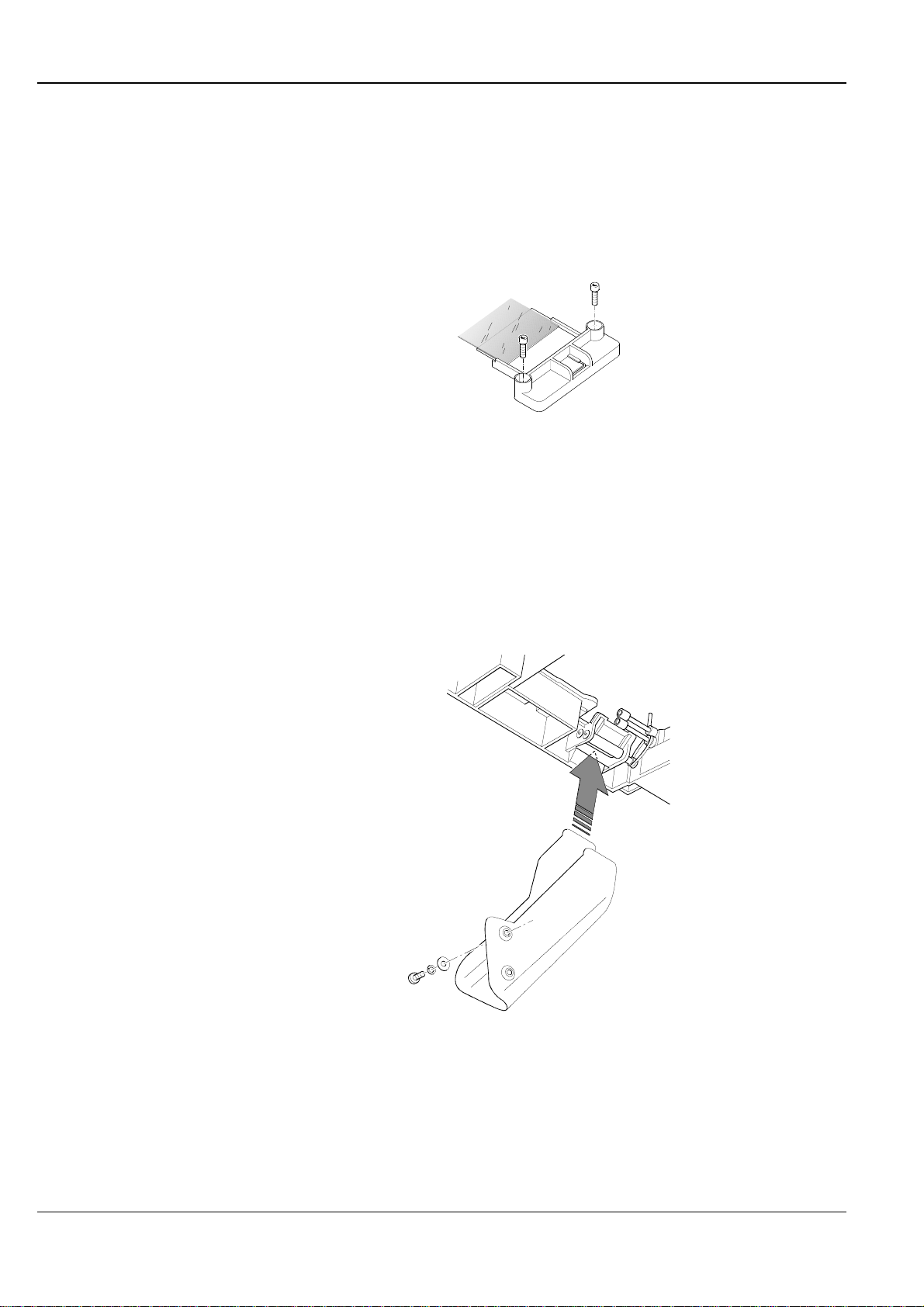
Shutter
Dismounting the shutter
- Remove the negative carrier
- Push the Scanner to the right up to the stop
- Dismount the mirror (two screws)
#Spiegel01
- Fold up the dryer of the Film Processor
- Take out the last STB rack
- Unscrew the film supply (see "Flim supply, dismounting the film supply")
- Unscrew the top film chute (2 screws)
Note: Mind the correct position of the chute before pulling it out.
The left top edge of the chute is between the negative carrier and the active film output
#Frtsch01
- Pull out the film chute towards the bottom
- Push up the solenoid
The shutter is held on the darkroom housing only by magnetic force
1.6 26.10.95 AGFA MSC 101
Page 9
Mechanical Color Printer
- Pull out the shutter
- Installation in reverse order
Mind the correct position of the chute and the shutter (the shutter must lock in safely)
Note: If it is difficult to install the chute, don’t despair, this is normal! Make only sure that the
active film output is not damaged.
Paddle height
Adjust the height of the paddle with D-Cut shims so that the smallest distance between
the paddle and the housing is 0.1mm...0.5mm (over the entire swivel area of the paddle)
when it is turned (solenoid up). In normal position (solenoid down), the paddle may rub
slightly on the friction rib on the housing.
The paddle must not touch the metal cover when the latter is in place.
Note: At least one D-Cut shim is required
Shutter adjustment
Turn the solenoid in the 3 oblong adjusting holes until the bouncing and the noise at both
stops is minimised.
#Shutter
1 Oblong adjusting holes 2 D-Cut shim(s)
AGFA MSC 101 26.10.95 1.7
Page 10

Mechanical Color Printer
Color Printer, Scanner Area
General
It is not mentioned in particular that the connecting lines must be disconnected for the
removal of a unit.
Attention! Never touch screws secured with red lacquer, except when required in the manual.
Tools
The following tools and auxiliary means are needed:
- Expansion pliers for retaining rings
- Set of gauges for the film plane
1 Gauge 135 2 Zero position gauge
(Part number unknown at the moment of printing)
#Lehre2
AGFA MSC 101 26.10.95 2.1
Page 11

Color Printer Mechanical
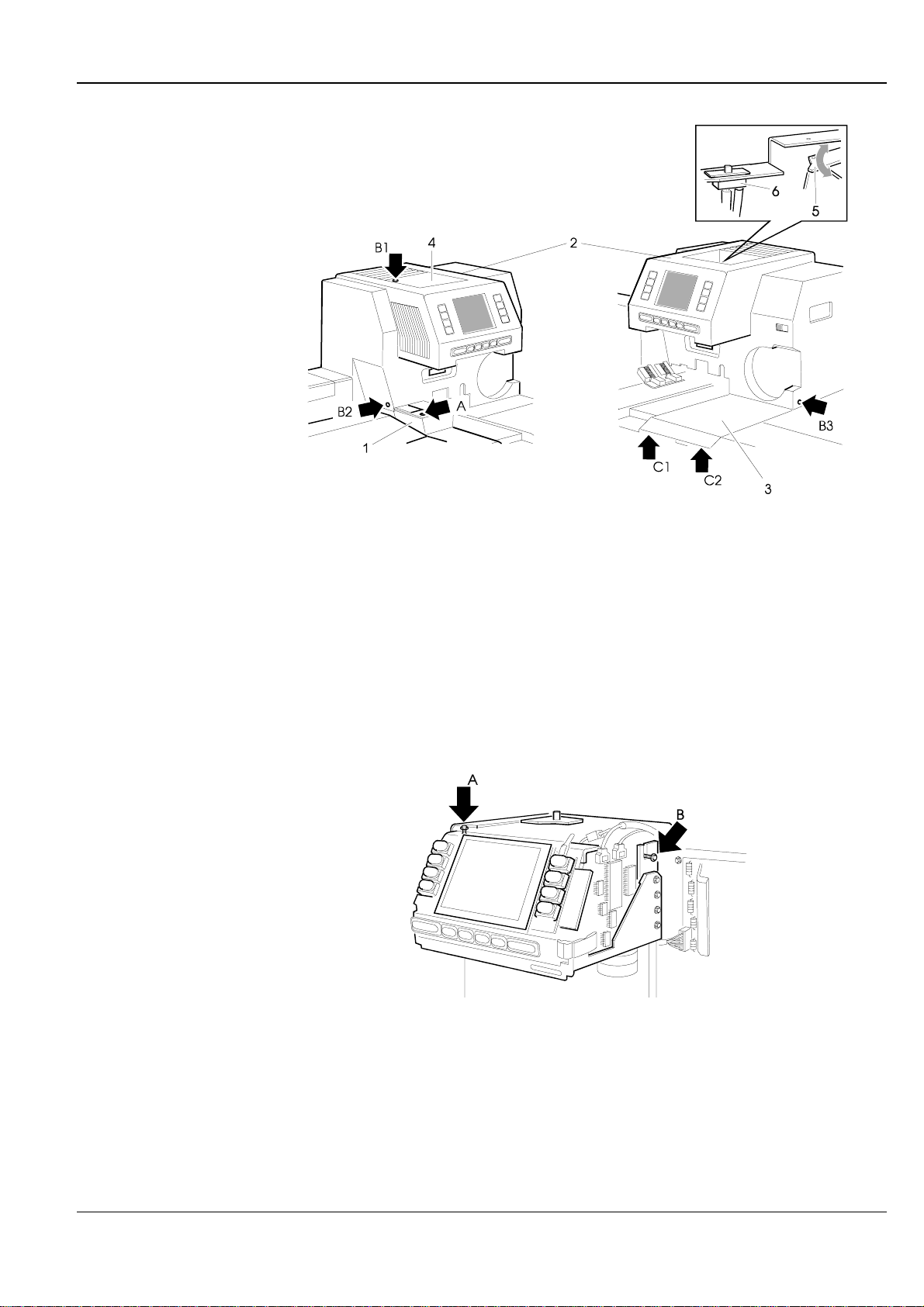
Removing the Covers
- Take out the mirror box
- Dismount the film take up
- Fold up the dryer of the Film Processor and open the cover of the Paper Processor
Feeder
- Unscrew screw A
- Take off the cover
Computer
- Take off the lamphouse cover
* Open the cover
* Separate the cover from the reflector bracket (the cover simply snaps on the
bracket)
The reflector unit moves up.
Attention! Never operate or jumper the lamp switch while the reflector unit is out! The heat of
Attention! In normal operating position (computer cover and lamphouse cover put on), the
Negative carrier
the lamp would immediately destroy the filters.
- Move the reflector back in and hold it down with the reflector pressure part.
reflector unit must not be held down by the pressure part !
- Unscrew the screws B1, B2, B3 d
- Pull out the cover towards the front
- Unscrew the screws C1 and C2
after having opened the Printer and lane distributor door
- Pull the cover out towards the front and lift it off
2.2 26.10.95 AGFA MSC 101
Page 12
Mechanical Color Printer
1 Feeder cover 4 Lamphouse cover
2 Computer cover 5 Reflector pressure part
3 Negative carrier cover 6 Lamp switch
Dismounting the Display Holder
- Unscrew screw A
- Slacken screw B
- Pull the unit out and up
#Agfacove
#Displ
AGFA MSC 101 26.10.95 2.3
Page 13

Color Printer Mechanical
Filter Unit
Replacing the cold light mirror
- Dismount the display holder (see there)
- Unscrew the marked screws
- Remove the cover
- Remove the holding spring
- Take out the mirror
- Installation in reverse order
Attention! The coated side of the mirror must point to the lamp!
Replacing the IR filter
Attention! The marked side (ring on the edge) must point to the lamp!
Dismounting the filter unit
#Kaltlich
1 Cover 3 Cold light mirror
2 Holding spring
The IR filter is located under the cold light mirror
- Take out the cold light mirror (see "Replacing the cold light mirror")
- Take out the holding spring
- Replace the filter
- Dismount the display holder (see there)
- Open the reflector pressure part (= move the pressure part in Home position)
- Unscrew the three marked screws
- If necessary, move in the filter paddle by hand
(If the filters are out, they may get damaged when the filter unit is dismounted).
2.4 26.10.95 AGFA MSC 101
Page 14

Mechanical Color Printer
- Dismount the filter unit
* Lift the unit a little and pull it out towards the front until it comes free
* Carefully press on the solenoids from below and tilt the unit towards the front
Attention! Do not reach into the light path opening or press on the filters!
* Pull out the unit towards the front
- Installation in reverse order
Make sure that all lines are installed and fastened again correctly so that they do not
hinder the filters.
Dismounting the lamp switch
Illustration see above
- Dismount the fan
- Strip the cable lugs off the switch
- Press on the switch locks (1) and pull the switch up (2)
#Filt_uni
1 Solenoids 3 Lamp switch
2 Reflector pressure part
AGFA MSC 101 26.10.95 2.5
Page 15

Color Printer Mechanical
Replacing the filter paddles and the solenoids
- Dismount the filter unit (see there)
Filter paddle:
- Remove the retaining ring
Note: The retaining ring is clamped directly on the (grooveless) solenoid shaft.
- Lift the paddles
Very stiff!
- Installation in reverse order
* It should not be necessary to adjust the paddle height.
This may only be necessary by inserting or removing D-Cut shims when a paddle
grinds. One D-Cut shim must remain on the shaft.
* Push the paddles on the shaft up to the stop
* Press the retaining ring firmly on the paddles
Solenoids:
Note: Mark the position of the solenoids (facilitates the reinsertion of the solenoids later on)
- Unscrew the fastening screws (3 screw each)
The screws of the Y, M, C solenoids are accessible from above, those of the mask
filter and light attenuator solenoids from below.
- Take out the solenoid
- Installation in reverse order
No adjustment required
#Filtpadd
1 Retaining ring 3 D-Cut shim
2 Filter paddle
2.6 26.10.95 AGFA MSC 101
Page 16

Mechanical Color Printer
Film Supply
Work on the film supply is performed in dismounted condition
Dismounting the film supply
- Dismount the film supply (2 screws)
Changing the rubber rollers
Note: The shaft can only be pushed in when its chamfer is in alignment with the chamfer of
#Flmsupl4
Top roller:
- Take off the lock washer and thrust out the shaft
- Replace the roller
- Assembly in reverse order
the shaft holder bores.
- Check the light sensors for correct triggering; readjust them, if necessary (see
"Adjustment of the light sensors")
#Fsobroll
1 Top rubber roller 3 Shaft
2 Lock washer 4 Shaft holder
AGFA MSC 101 26.10.95 2.7
Page 17

Color Printer Mechanical
Bottom roller:
- Remove all four lock washers from the shaft
- Pull out the shaft a little and thrust out the driver pin
- Pull out the shaft
Mind the washers (note their location)
- Push the roller off the shaft
- Assembly in reverse order
Attention! The roller turns only in one direction! Push the roller on the shaft so that it turns
in film drive direction when the shaft is held tight!
- Check the light sensors for correct triggering; readjust them, if necessary
(see "Adjustment of the light sensors")
#Flmsupl1
Free running direction when the shaft is held tight
1 Shaft 3 Driver pin
2 Roller 4 Lock washer
Changing the flap
- Pull out the shaft of the bottom rubber roller (see "Changing the rubber rollers")
- Hang out the leg spring
Note: For the assembly later on, it is useful to mark the contact point of the spring on the
eccentric of the flap.
- Unscrew the film guide plate
2.8 26.10.95 AGFA MSC 101
Page 18

Mechanical Color Printer
- Remove the connecting rod from the eccentric of the flap
- Remove the holding bracket
- Take out the flap
- Installation in reverse order
- Check the light sensors for correct triggering; readjust them, if necessary
(see "Adjustment of the light sensors")
#Flmsupl2
Free running direction when the shaft is held tight
1 Flap 4 Holding bracket
2 Film guide plate 5 Leg spring
3 Connecting rod
Replacing the motors
The motors are held in the motor holder only by brackets
- Remove the holder bracket (2 screws)
- Pull out the motor
- Installation in reverse order
Be careful when tightening the screws; the plastic thread gets easily damaged.
AGFA MSC 101 26.10.95 2.9
Page 19

Color Printer Mechanical
Replacing the lifting magnet
- Unscrew the light sensors
- Remove the lock washer
- Remove the cover plate (3 screws)
- Lift the light sensor actuator
- Thrust out the driver pin
- Lift out the magnet
Make sure that the second driver pin does not get lost when the shaft is moved
- Installation in reverse order
- Check the light sensors for correct triggering; readjust them, if necessary
(see "Adjustment of the light sensors")
#Flmsupl3
1 Light sensors 4 Driver pin
2 Cover plate 5 Magnet
3 Light sensor actuator
2.10 26.10.95 AGFA MSC 101
Page 20

Mechanical Color Printer
Adjustment of the light sensors
The adjustment can be performed while the film supply is dismounted. Only the light
sensors need to be connected. Check the light sensors in the test mode of the MSC 101.
The light sensors are relocated together.
Note: The indications "horizontal" and "vertical" refer to the mounting position of the film supply
Horizontal position of the flap:
- Put a 1mm spacing piece (e.g. twist drill) under the film guide plate
* Put it in in such a way that it is jammed between the film guide plate and the goose
pimple(s) of the flap when the latter is horizontal.
1 Film guide plate 3 Spacer 1mm
2 Flap
- Move the flap in horizontal position in the test mode
- If the light sensor for the horizontal position does not respond:
* Slacken both fastening screws
* Shift the light sensors until the light sensor for the horizontal position responds.
The light sensor for the vertical position must not send a signal
- Tighten the screws
- Move the flap in vertical position
- Move the flap several times in vertical and in horizontal position.
The light sensor for the horizontal position must respond each time, if not, the
adjustment must be repeated.
Attention! The actuator must not rub on the light sensors !
If necessary, slacken the fastening screws one by one, bend the jammed light sensor in a
better position, check its correct triggering, and tighten the screws again.
#101skiz
AGFA MSC 101 26.10.95 2.11
Page 21

Color Printer Mechanical
Vertical position of the flap:
- Let the flap drop in vertical position
- Check the light sensor for correct triggering
Only the light sensor for the vertical position may send a signal.
If the light sensor does not respond, slacken the fastening screw again and bend the
light sensor until it is triggered.
Attention! The actuator must not rub on the light sensors !
If necessary, slacken the fastening screw, bend the jammed light sensor in a better
position, check its correct triggering, and tighten the screws again.
2.12 26.10.95 AGFA MSC 101
Page 22

Mechanical Color Printer
Film Feeder
Dismounting the Film Feeder
Attention! Dismount and mount the Feeder only while the film supply is dismounted (see also
"Dismounting the film supply"), otherwise the Feeder or the film supply may get
damaged.
The Feeder is fastened to the negative carrier from above by means of two screws.
- Unscrew the fastening screws
- Lift off the Feeder
Once the Feeder has been removed, all units are accessible without problems; for this
reason, there is no need for detailed assembly/disassembly instructions for the single
parts.
The Feeder adjustment is more difficult. It is described on the following pages.
Tension of the drive belt
The belt tension can be adjusted by relocating the motor (4 screws).
Rough adjustment of the film guide
Adjustment becomes necessary when the gears are relocated on the shafts (e.g. after
replacement of the toothed belt).
- Unscrew the cover plate
- Dismount gear B and
turn the stop ring to the right end of shaft B
- Undo the connection between skid A ↔ shaft A (grub screw)
- Hold shaft A and screw in gear A until the threadless end of the shaft stands out of the
associated bush about 2mm
The shoulder on gear A should not slip out of its hole!
- Push skid A to the middle up to the stop
#101skiz
- Fasten skid A on shaft A again
- Turn gear A about half a turn in ccw direction
- Undo the connection between skid B ↔ shaft B (grub screw)
- Push skit B to the outside up to the stop
- Shift shaft B so that the threadless end of the shaft stands out of the associated bush
about 2mm.
AGFA MSC 101 26.10.95 2.13
Page 23

Color Printer Mechanical
- Fasten skid B on shaft B again
after having ascertained that
* there are still 2mm standing out and
* the skid is on the extreme outside.
- Push skid B against skid A and hold it tight
- Turn in the stop ring until skid B starts moving to the right
- Put on gear B
- Screw on the cover plate
- Move the Feeder in position 120 and in zero position in the test mode:
The threadless end of a shaft must not penetrate into the associated bush in neither of
the two positions (projection 0.5mm ... 1.8mm). Repeat the rough adjustment, if
necessary.
Mounting the Film Feeder
Attention! Be sure to dismount the film supply before installing the Feeder
#Feeder
1A Skid A 1B Skid B
2A Shaft A 2B Shaft B
3A Gear A 3B Gear B
4Stop ring 6 Lug
5Cover plate
If the film supply is not dismounted, the Feeder or the film supply may get damaged
- Dismount the film supply (see "Dismounting the film supply"); the cables need not be
disconnected
- Lift the top film transport roller
- Put the Feeder on the negative carrier diagonally from above,
inserting the film exit flap between the top and bottom film transport roller
- Screw the Feeder back on
2.14 26.10.95 AGFA MSC 101
Page 24

Mechanical Color Printer
Adjustment of the film guide
Adjustment is with the Feeder in place (see "Mounting the Feeder")
- Open the Feeder skids by hand (turn the toothed belt gear) until the gauge 135 just fits
Attention! Never move the skids towards the gauge because in this case they would not be
symmetric with the optical axis!
- Push in the gauge until it reaches into the film guide of the negative mask 135F
If it is impossible to push in the gauge, or too much backlash (max. 0.3mm):
* Unscrew the skids from the shaft (one grub screw each) and shift them as
appropriate
- Move the Feeder in position 120 and in zero position in the test mode:
The threadless end of a shaft must not penetrate into the associated bush in neither of
the two positions (projection 0.5mm ... 1.8mm). Repeat the rough adjustment, if
necessary (see "Rough adjustment of the film guide").
1 Gauge 3 Negative mask
2 Feeder skids
Adjustment of the channel width scanning
Adjustment is with the Feeder in place (see "Mounting the Feeder")
- Put in the zero position gauge
- Close the Feeder manually (turn the toothed belt gear) until the gauge is jammed (zero
position)
- Release the light sensor actuator and pull it out of the light sensor
- Push the actuator back into the light sensor until the latter is triggered (check in the test
mode of the MSC 101)
- Fasten the actuator again
#101skiz
AGFA MSC 101 26.10.95 2.15
Page 25

Color Printer Mechanical
- Open the skids for film size 120 (via the test mode)
- Move the skids back to zero position (via the test mode)
- The gauge must fit again with a backlash of ±0.1mm, if necessary, correct or repeat
the adjustment
Note In zero position, the skids are not symmetric with the optical axis.
#Feedkuf
1 Light sensor actuator
2.16 26.10.95 AGFA MSC 101
Page 26

Mechanical Color Printer
Negative Carrier
Some parts (e.g. film drive motors, rocker motors) are only accessible after the negative
carrier has been dismounted
Dismounting the negative carrier
- Unscrew the film supply (2 screws)
Attention! Never unscrew banjo screws secured with red lacquer!
- Unscrew the marked screws
- Lift out the negative carrier
Active Film Output: Dismounting or changing the toothed belt
The film output must be dismounted or at least slackened to change the toothed belt.
The film output is fastened under the negative carrier with two screws. It is accessible
without problems after the negative carrier has been removed.
#Negcar01
1 Banjo screw. Do not touch! 2 Active film output
AGFA MSC 101 26.10.95 2.17
Page 27

Color Printer Mechanical
Changing the lifting magnet, toothed belt, auxiliary drive shaft
Lifting magnet:
- Unscrew the marked screws (grub screws)
- Pull off the magnet
Belt:
- Pull off the additional gear (incl. armature plate)
- Change the belt
Auxiliary drive shaft:
- Unscrew the holder (3 screws)
- Pull out the shaft
The bearings can be taken off after removing the lock washer.
- Mind the correct position of the holder upon reassembly (see illustration).
#filmantri
1 Magnet 4 Holder
2 Armature plate 5 Single print drive shaft
3 Gear 6 Lock washer
2.18 26.10.95 AGFA MSC 101
Page 28

Mechanical Color Printer
Working on the rockers
Rocker motor(s) and eccentric blocks:
Since the assembly/disassembly of both rocker motors and eccentric blocks are identical,
the procedure is described only for one motor.
- Unscrew the cover plate (incl. light sensor)
- Pull out the motor
- Remove the lock washer on the eccentric block
Attention! Do not dismantle the eccentric block, but replace it as a complete unit!
- Pull out the eccentric block
To pull out eccentric block A, the gear in front of it need not be removed. It is sufficient
to pull out rocker shaft A a little.
Rocker disassembly:
- Remove the lock washer on the rocker eccentric
- Pull out rocker shaft B. Mind the washers, note their location !
- Remove the lock washer in the rocker
Attention! Do not try to detach the eccentric from the rocker.
- Strip off the rocker with the eccentric
AGFA MSC 101 26.10.95 2.19
Page 29

Color Printer Mechanical
#Wippe01
1a Cover plate A 1b Cover plate B
2a Motor A 2b Motor B
3a Eccentric block A 3b Eccentric block B
4a Rocker shaft A 4b Rocker shaft B
5a Rocker 5b Rocker eccentric
Rocker assembly:
- Remove the plates
- Dismount the bottom rubber roller
* Lock the shaft: Push the pin (or an Allan key) through the hole in the motor shaft
2.20 26.10.95 AGFA MSC 101
Page 30

Mechanical Color Printer
* Unscrew the marked screw
* Strip off the roller
- Push the rocker a few mm on the shaft with the spring inserted
(Spring position in the rocker, see illustration below)
- Turn the rocker until it rests on the motor shaft
(The eccentric hangs down)
- Turn the spring until its long leg rests on the rocker
(The leg moves away from the rubber roller, in direction of the motor shaft)
- Push the rocker and spring fully on the shaft
The short leg of the spring slides in the recess on the shaft.
- Turn the rocker in opposite direction to the spring tension until it rests on the negative
carrier. (The eccentric rests on the negative carrier as well)
- Fasten the bottom rubber roller on the motor shaft again
- Put the lock washer back into the rocker
- Screw the plates back on the negative carrier
#Wippe02
1 Plates 3 Bottom rubber roller
2 Motor shaft 4 Rocker
AGFA MSC 101 26.10.95 2.21
Page 31

Color Printer Mechanical
Changing the light sensors for the negative coding
- Slightly press down the quick-action locks of the light sensor holder and push the unit
to the back
- Lift the light sensor
1 Light sensor holder with sensor 3 Locking button
2 Cover plate
Replacing the negative carrier lock
See the above illustration.
- Unscrew the cover plate (2 screws)
- Take out the lock
Attention! Change only the complete lock!
- Installation: Mind the correct position of the locking button (see illustration above)
#Negcar02
2.22 26.10.95 AGFA MSC 101
Page 32

Mechanical Color Printer
Scanner
The slide motor is directly accessible, the toothed belt and the Scanner slide, after
removal of the negative carrier (see "Negative carrier, dismounting the negative carrier")
Reference value for the toothed belt tension: Slack of 3mm at approx. 2.5N.
All measuring cells are located directly on the Scanner board. It can be removed from the
Scanner slide and reinserted without problems.
1 Scanner tray 4 Scanner slide
2 Slide motor 5 Scanner board
3 Toothed belt
#Scan01
AGFA MSC 101 26.10.95 2.23
Page 33

Color Printer Mechanical
PC Holder
Dismounting the holder
- Unscrew the screws A (2 screws)
- Lift the holder up and off
Replacing the hard disk and/or the disk drive
Hard disk:
- Unscrew screw B
- Push the hard disk to the back
- Lift out the hard disk
- Installation in reverse order
Disk drive:
- Dismount the hard disk (see above)
- Take out the filter power drive board
- Unscrew the screws C (4 screws)
- Take out the disk drive
- Installation in reverse order
#Pc_traeg
1 Hard disk 3 Disk drive
2 Filter Power Drive Board
2.24 26.10.95 AGFA MSC 101
Page 34

Mechanical Film Processor
Film Processor
General
It is not mentioned in particular that the connecting lines must be disconnected for the
removal of a unit.
- Never touch screws secured with red lacquer, except when required in the manual.
Tools
The following tools and auxiliary means are needed:
- No special tools required
Dryer Block
The dryer block is composed of the following units
- Film feeder block
Removing the covers
Note: The Film Processor may not heat up when the cover is open, even not when the dryer is
- Film dryer block and
- Leader Cutter.
- Remove the cover of the emergency film removal
- Fold up the dryer
- Unscrew the fastening screws (6 screws at the bottom edge)
- Strip off the cover
Provide the dryer rack and the heater with an additional cover:
- Unscrew the fastening screws (2 screws at the crossover dryer block ↔film feeder
block)
down and correctly locked. Reason: There are other control switches on the rear side
next to the Reed switch on the locking button (not visible from above). Without the cover,
the dryer location is slightly different. For reason of manufacturing tolerances, the control
switches may not be actuated in this case.
AGFA MSC 101 26.10.95 3.1
Page 35

Film Processor Mechanical
Changing the Leader Cutter
The Leader cutter should not be touched. Since its adjustment, removal and reinstallation
would be too time-consuming, the Leader cutter is replaced only as a whole block.
- Unscrew the marked screws (on the dryer underside)
- Pull the Leader Cutter towards the front and lift it out
Heater
#Lc01
Attention! Switch off the current on the main switch!
Remove the bimetal fuse strip:
Remove the fuse only if it does not switch through when the red touch-contact key is
pressed.
- Remove the cover (screws A)
- Unscrew the fuse (screws B)
Dismount the heater element:
- Remove the cover (screws A)
- Remove screw C
- Lift out the heater element
Change the thermofuse:
The thermofuse is easily accessible after the heater element has been removed (see
above).
3.2 26.10.95 AGFA MSC 101
Page 36

Mechanical Film Processor
Dismount the heater fan:
- Dismount the heater element (see above)
- Unscrew the screws D
- Lift out the fan
#Ftrock01
1a Cover 3 Heater element
2a Bimetal fuse strip 4 Heater fan
2a Touch-contact key
AGFA MSC 101 26.10.95 3.3
Page 37

Film Processor Mechanical
Changing the dryer rack
- Dismount the Leader Cutter (see "Changing the Leader Cutter")
- Dismount the heater fan (see above)
Note: Dismounting the heater fan is not absolutely necessary but simplifies the removal of
the dryer rack.
- Unscrew the marked screws
- Take out the rack
- Installation in reverse order
Make sure that the ball bearing sits correctly in the holder on the drive shaft.
#Ftrock02
1 Dryer rack 4a Drive shaft
2 Leader Cutter 4b Holder
3 Heater fan
■
3.4 26.10.95 AGFA MSC 101
 Loading...