

Aerowerks TA Installation Manual

TABLE OF CONTENTS
INSTALLATION & OPERATING INSTRUCTION MANUAL FOR MODEL TA--TRAY
ACCUMULATOR CONVEYOR SYSTEM
1. INSTALLATION __________________________________________________ 2
1.1. GENERAL INSTALLATION____________________________________________2
2. OPERATION______________________________________________________ 3
2.1. GENERAL DESCRIPTION _____________________________________________3
2.2. OPERATION_________________________________________________________3
2.2.1. General Instructions _______________________________________________________ 3
3. MAINTENANCE __________________________________________________ 3
3.1. REPAIR INSTRUCTIONS ______________________________________________3
3.2. CHAIN TAKE-UP_____________________________________________________4
3.2.1. Chain Take-up – Frame ____________________________________________________ 4
3.2.2. Chain Take-up – Chain Link_________________________________________________ 5
3.3. ELECTRICAL SYSTEM _______________________________________________5
3.4. LUBRICATION ______________________________________________________5
3.4.1. Gearbox Motor ___________________________________________________________ 5
3.5. MAINTENANCE SCHEDULE __________________________________________5
3.5.1. Daily ___________________________________________________________________ 6
3.5.2. Monthly_________________________________________________________________ 6
3.5.3. Semi-Annually ___________________________________________________________ 6
3.6. REPLACING GEARBOX MOTOR _______________________________________6
3.7. REPLACING SPROCKETS _____________________________________________7
3.8. TROUBLE SHOOTING TRAY ACCUMULATOR CONVEYOR _______________8
3.9. REPLACEMENT PARTS LIST __________________________________________9
4. WARRANTY FOR MODEL TA - TRAY ACCUMULATOR CONVEYOR_ 11
4.1. WARRANTY PERIOD ________________________________________________11
4.2. WARRANTY COVERAGE ____________________________________________11
4.3. GENERAL__________________________________________________________11
1

INSTALLATION & OPERATING INSTRUCTION MANUAL FOR
MODEL TA – TRAY ACCUMULATOR CONVEYOR SYSTEM
The following instructions for installation and maintenance of Model Tray Accumulator Conveyor
System should be carefully read and followed. Any deviation will affect the warranty of this
machine. The conveyor unit shall be installed by or under the supervision of Aerowerks or its
authorized representatives.
NOTE: A “Layout Drawing” representing the overall conveyor system, specific to this
project is included in this manual. The owners and maintenance personnel should become
familiar with this document.
1. INSTALLATION
1.1. GENERAL INSTALLATION
The following instructions are for the installation of the Model TA Tray Accumulator. Please read
and follow the instructions carefully. Some parts of the installation require extreme care.
1. Set and level the table in place.
2. Set the Tray Accumulator above the table.
3. Tack weld all the pre fitted field joints.
4. Make all field connections.
5. Level entire system.
6. Fully weld and polish the joints to obtain the smooth surface.
7. Apply silicone and seal the gaps between walls and conveyor system. Use only food grade
silicone.
8. Electrical wire connections shall be made between the main control panel and the auxiliary
remote start/stop stations.
9. The electrical building connection should be done at this time.
10. Remove the top chain guard cover and the motor cover.
11. Remove the key between the motor shaft and the drive sprocket.
12. Start the conveyor motor and make sure that the drive shaft is turning in the direction marked
on the motor. If it is not, then switch the two motor leads to get the desired direction of
rotation.
2

13. Once the correct motor direction is established, stop the unit, replace key and secure it in its
position with the setscrews.
14. Replace all the chain covers.
15. Mount all the ladders and carriers. The system is now ready for use.*
* The Tray Accumulator may be accompanied with other conveyors. Please follow the installation
instructions of those conveyors before starting system.
2. OPERATION
2.1. GENERAL DESCRIPTION
The Tray Accumulator Conveyor System forms an integral part of the soiled dish table. It is
designed to accumulate soiled trays from the cafeteria to the dish room for scrapping and sorting.
Never load any dishes on the accumulator unless they are on a tray. Furthermore, never attempt to
convey any kitchen equipment such as pots and pans. Overloading will seriously damage this unit.
2.2. OPERATION
2.2.1. G
1. Turn the ‘MAIN DISCONNECT’ switch to “ON” position.
2. Then press the green ‘START’ button marked for ‘Tray Accumulator Conveyor’, located on
the control panel. Some systems may have auxiliary push button stations located in other
required areas
3. Adjust the setting to the desired speed. Recommended speed setting of the conveyor is 15
when the volume of the tray to be handled is low and 50 when the volume is high. Running
the conveyor at higher speed may not provide adequate time for loading or unloading.
4. To shut down the conveyor, push the red ‘STOP’ button marked for the ‘Tray Accumulator
Conveyor’. Then turn the ‘MAIN DISCONNECT’ switch to ‘OFF’.
ENERAL INSTRUCTIONS
3. MAINTENANCE
3.1. REPAIR INSTRUCTIONS
Our Conveyor Systems are built with high quality materials to provide a reliable service and trouble
free operation. The service life of the equipment can be extended by regular maintenance. It is
strongly recommended to get the equipment serviced by Aerowerks or its authorized agent.
3
3.2. CHAIN TAKE-UP
The Aerowerks Tray Accumulator Conveyor utilizes only one chain, which is known as the Drive
Chain. This chain is located at the top of the Tray Accumulator unit. Generally this chain never
needs any replacement in its service life. However it is required to remove accumulated stretch in
the chain time to time, for the smooth operation of the equipment. This can be accomplished either
by extending the frame (Recommended for small adjustments) or by removing one of the chain links
(Recommended for larger adjustments).
3.2.1. C
HAIN TAKE-UP – FRAME
The chain take-up of the tray accumulator system involves extending the frame of the unit. This
should be preformed if small adjustment is needed (0-3 inches).
1. Disconnect the power to the equipment to avoid an accidental starting.
2. Remove the hood panel, curved end panel and both side panels on the drive as well as the tail
end of the machine.
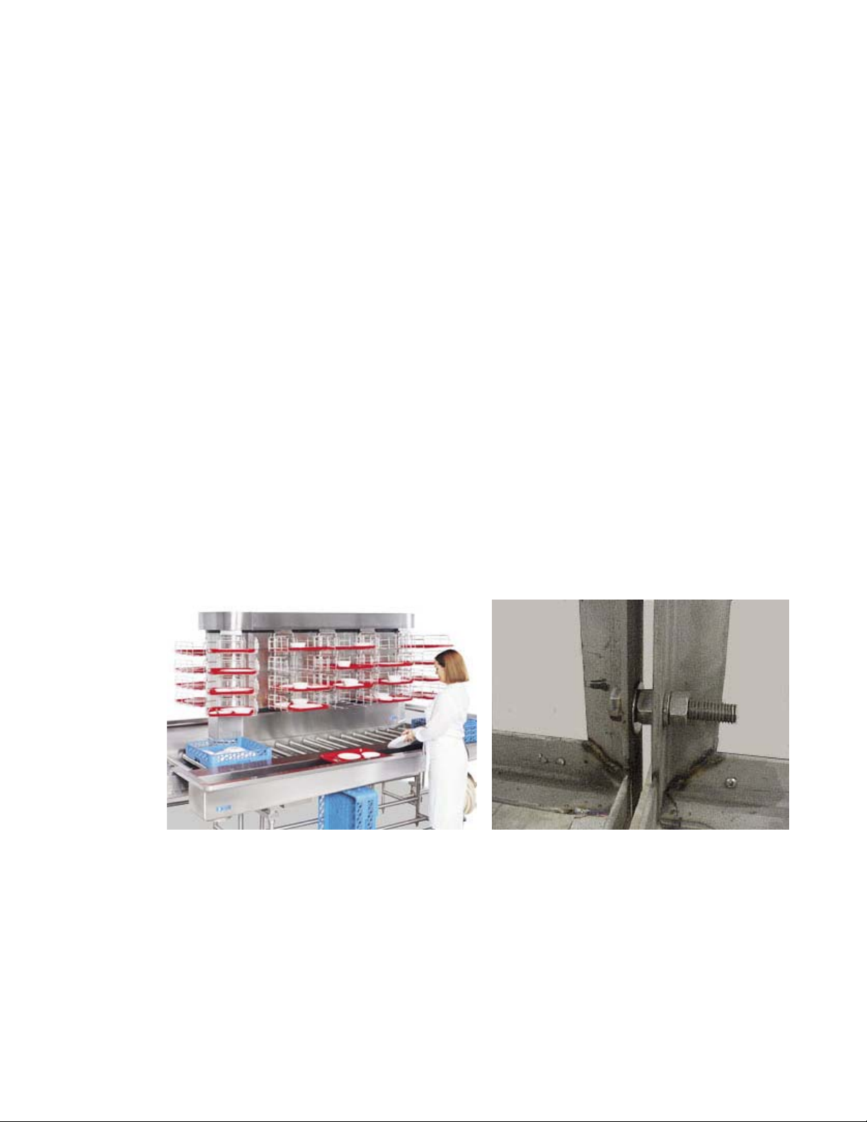
3. You will see that the frame is built in modular sections. You need to adjust the two large
take-up bolts located on the vertical support bars of the frame. Please make sure to adjust the
bolts by turning equally on either side at the each end in order to keep the chain centered and
keep the frame aligned.
Tray Accumulation System Take Up Bolts
Figure 1.0 Figure 2.0
4. Before replacing the panels run the system to make sure that the operation is smooth and
chain take-up is adequate. Extreme care to be taken during the test run of the equipment with
exposed chain to avoid any accident.
5. Stop the accumulator and replace all the panels.
4
 Loading...