

Page 1
Toll Free : 888-774-1616
Fax : (905)-363-6998
- 1 -
www.aero-werks.com
INSTRUC TION MANUAL FOR MODEL PRC
POWER ROLLER CONVEYOR
Aerowerks©2017
Page 2
Toll Free : 888-774-1616
Fax : (905)-363-6998
- 2 -
www.aero-werks.com
TABLEOFCONTENTS
1. OPERATION 3
1.1. GENERAL DESCRIPTION 3
1.2. OPERATION 3
1.2.1. GENERAL INSTRUCTIONS 3
2. MAINTENANCE 4
2.1. CHAIN TAKEUP 4
2.1.1. GEAR MOTOR TAKEUP 4
2.1.2. CHAIN LINK TAKEUP 4
2.2. ELECTRICAL SYSTEM 5
2.3. LUBRICATION 6
2.3.1. BUSHINGS 6
2.3.2 GEAR MOTOR 6
2.4. MAINTENANCE SCHEDULE 6
2.4.1. DAILY 6
2.4.2. MONTHLY 6
2.4.3. SEMI-ANNUALLY 7
2.5. REPLACING FRAME BUSHINGS 7
2.6. REPLACING GEAR MOTOR 7
2.7. REPLACING ROLLER SHAFTS 8
2.8. REPLACING SPROCKETS 9
3. TROUBLESHOOTING 10
4. MODEL PRC- POWERED ROLLER CONVEYOR PARTS 11
5. WARRANTY FOR MODEL PRC- POWERED ROLLER CONVEYOR 13
5.1. WARRANTY PERIOD 13
5.2. GENERAL 13
5.3. WARRANTY COVERAGE 13
Aerowerks©2017
Page 3
Toll Free : 888-774-1616
Fax : (905)-363-6998
- 3 -
www.aero-werks.com
INSTRUCTION MANUAL FOR MODEL PRC- POWER ROLLER
1. OPERATION
1.1. GENERAL DESCRIPTION
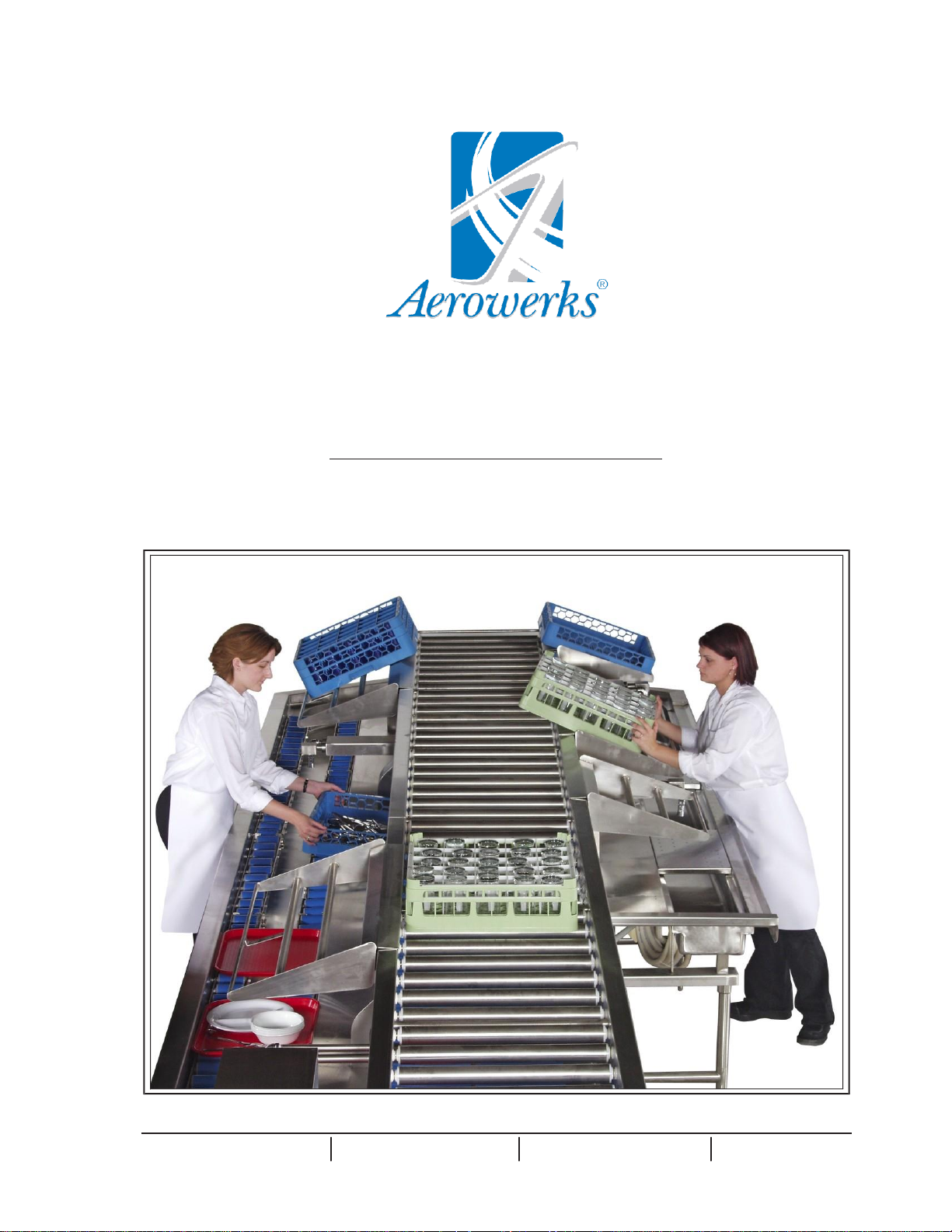
The Power Roller Conveyor usually forms an integral part of the scrapping table. Its
function is to convey 20” x 20” dish racks to the gravity roller conveyor or directly to the
dishwasher. This conveyor has been custom designed to suit your application. Do not
use this conveyor to convey items other than 20” x 20” dish racks.
The low-pressure accumulation principle treats each roller as an individual unit. Hence
when the racks get accumulated, the rollers underneath them stop turning where as the
remaining rollers will continue to function.
1.2. OPERATION
1.2.1. GENERAL INSTRUCTIONS
1. Turn the 'MAIN DISCONNECT' switch on the main control panel to “ON” position.
2. Push the green 'START' button marked 'Rack Conveyor'. Some systems may have
auxiliary push button stations located in other required areas.
3. To shut down the conveyor, push the red 'STOP' button marked 'Rack Conveyor'.
Then turn the 'MAIN DISCONNECT' switch to 'OFF'.
Note: Power rollers run at constant speed at low pressure driving force, allowing
accumulation to take place without having to stop the conveyor.
Aerowerks©2017
Page 4
Toll Free : 888-774-1616
Fax : (905)-363-6998
- 4 -
www.aero-werks.com
2. MAINTENANCE
2.1. CHAIN TAKEUP
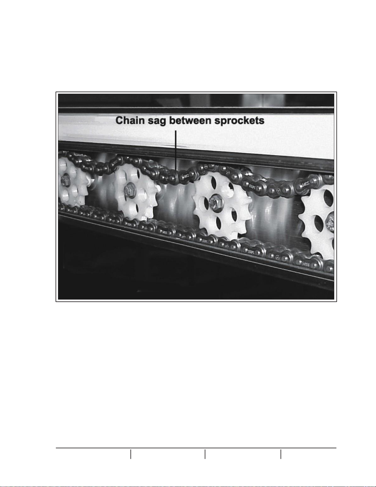
Generally the drive chain does not need any replacement. However, it requires time-totime adjustment to remove the slack developed in the chain due to the tension. This can
be accomplished either by moving the gear motor away from its initial position or by
removing a few links from the chain. The first method is recommended for the small
adjustments where as the second method is ideal choice for the large adjustments.
2.1.1. GEAR MOTOR TAKEUP
1. Disconnect the power to avoid accidental starting.
2. Remove the drive housing
cover.
3. Loosen the gear motor mounting bolts and gently lower the gear
motor.
Since the drive sprocket mounted the motor shaft, lowering the motor reduces
the slack in the chain.
4. Tighten the gear motor mounting bolts.
5. Run the system to make sure that the chain take-up is adequate and conveyor
operation is smooth.
6. Turn off the power and replace the side covers.
2.1.2. CHAIN LINK TAKEUP
1. Disconnect the power to avoid accidental starting.
2. Remove the drive housing cover.
3. Disconnect the chain preferably at the location of the removable link.
If it is hard to locate this link, use a chain breaker to disconnect at any other link.
Estimate the number of links required to be removed to eliminate the slack.
4. Remove the access links from the chain.
5. Reconnect the ends and turn on the power.
Aerowerks©2017
Page 5
Toll Free : 888-774-1616
Fax : (905)-363-6998
- 5 -
www.aero-werks.com
6. Run the system to make sure that the chain take-up is adequate and the conveyor
operation is smooth.
7. Turn off the power and replace the drive housing cover.
The electrical system control unit contains all relays, starters and other devices required
for the operation of conveyor control. There may be some auxiliary start-stop stations in
addition to the main control panel. Check the schematic for details. The main control
panel is NOT waterproof. Under no circumstances shall the control panel be hosed down
with water, during cleaning.
All fuses are sized individually for control or power circuit. Refer to electrical wiring
schematics when replacing fuses.
Figure 1.0 Normal Chain Sag between Plastic Sprockets
2.2. ELECTRICAL SYSTEM
Aerowerks©2017
Page 6
Toll Free : 888-774-1616
Fax : (905)-363-6998
- 6 -
www.aero-werks.com
Note: Power roller conveyor does not require any accumulation switches. Conveyor
operates as a low-pressure accumulation system the allows rollers to stop and
chain to continue running when product is accumulated on the conveyor.
2.3. LUBRICATION
2.3.1. BUSHINGS
Lubrication is required on the plastic bushings once every month. Always use the food
grade grease. Please follow the steps given below for the lubrication.
1. Shut down the conveyor and disconnect the power at main circuit breaker.
2. Apply the grease to the bushing located on the body of the conveyor and the rollers.
3. Do not over lubricate the bushings to avoid grease build up.
4. Inspect the roller shafts, bushings and sprockets for any damage. In most of the
cases, all these parts will have same extent of damage.
2.3.2. GEAR MOTOR
Gear motor is an integrated unit of a motor and step down gear box. The unit has been
lubricated for life and no maintenance lubrication is required.
2.4. MAINTENANCE SCHEDULE
Our conveyor systems are built to the high quality standards to provide a reliable service
and trouble free operation. The service life of the equipment can be extended services by
Aerowerks or authorized service agents. The following are the recommended
maintenance schedule.
2.4.1. DAILY
1. Hose down the conveyor and conveyor beds to clean and remove the foreign
materials. The conveyor can be running during a hose down period to expose all the
expose all the external surfaces of the rollers to the water jet.
2.4.2. MONTHLY
1. Inspect and replace any rollers or bushings that are damaged. Lubricate bushings.
Aerowerks©2017
Page 7
Toll Free : 888-774-1616
Fax : (905)-363-6998
- 7 -
www.aero-werks.com
2.4.3. SEMI-ANNUALLY
1. Remove the chain guard and inspect the chain tension. The excess slack in the
Chain shall be removed either by repositioning the motor or removing the chain links.
2. Inspect the sprockets, shafts and bushings for wear. Replace all the worn parts.
2.5. REPLACING FRAME BUSHINGS
When replacing the frame bushings, check the shafts, roller bushings and sprockets also
for replacement. A new bushing with an old shaft will get damaged very soon. The service
technician on site can easily replace the bushings in the body of the conveyor. But the
bushings in the individual rollers are difficult to replace. It is recommended to replace
complete roller or both of the bushings in the roller. Please refer figure 2 for the assembly
details of the roller. Please follow the steps given below to replace the bushings.
1. Disconnect the power from the main circuit breaker to avoid accidental starting.
2. Remove the side access cover to the drive chain. Disconnect the chain preferably
at the location of the removable link.
3. Remove the shaft and roller assembly. Remove the old bushings from the frame
and replace it with new ones. If new bushing is not able to fit by hand use a
softheaded hammer to lightly tap the bushing into its place. The bushing should
sit tight within the holes of the frame, without any crack.
4. Check to make sure that the roller is freely rotating. Misalignment in the bushings
will not allow the roller to rotate freely.
5. If all the rollers roll freely, assemble the chain by reconnecting the ends.
Adjust the chain length if necessary.
6. Turn on the power to the system to make sure that the power rollers
are running smooth.
2.6. REPLACING GEAR MOTOR
An electrician should do replacement of the gear motor. Before replacing the gear motor,
please follow the trouble shooting procedure to determine if the motor is defective. If the
gear motor is defective, please contact us with the model number and make of the gear
motor. Follow the steps given below to replace the gear motor:
Aerowerks©2017
Page 8
Toll Free : 888-774-1616
Fax : (905)-363-6998
- 8 -
www.aero-werks.com
1. Turn off the main circuit breaker to disconnect the main power to the conveyor.
2. Remove the side access cover of the drive chain.
3. Release the tension of the chain by adjusting the motor take-up.
If it is required to disconnect the chain, remove the connecting link or
use a chain breaker to disconnect.
4. Remove the key between the motor shaft and the drive sprocket.
Remove the drive sprocket.
5. Remove the mounting bolts and the gear motor.
6. Replace with new gear motor. Turn on the power to check the direction of rotation.
7. If the shaft rotates in the right direction, replace the drive sprocket and the key.
8. Assemble the chain and adjust the motor take-up.
9. Replace the cover and then test run the conveyor.
2.7. REPLACING ROLLER SHAFTS
At the time of replacing roller shaft, we must also look at the bushings and the sprockets
as well. An old shaft develops burs and jagged edges, which may damage the bushings.
Serious operational problems are likely to happen when a roller is used on a new
shaft with worn out bushings and sprocket or on an old shaft with new bushings and
sprocket.
It is necessary to replace new bushings and sprocket along with a new shaft.
Please refer to the parts list and contact us with part number and the model number.
Follow the steps given below when replacing the roller shaft:
1. Disconnect the power from the main circuit breaker to avoid accidental starting.
2. Remove the side access cover of the drive chain. Disconnect the chain preferably
at the location of the removable link. If the link is not found, use a chain breaker to
disconnect the chain.
3. Remove the old shaft and the sprocket. Remove the sprocket from shaft.
At this point replace the bushing and sprocket if required.
Aerowerks©2017
Page 9
Toll Free : 888-774-1616
Fax : (905)-363-6998
- 9 -
www.aero-werks.com
4. Bolt the sprocket to the new shaft and assemble it through the bushings
and the roller to the machine.
5. Reconnect the chain and adjust the chain take-up, if required.
6. Turn on the power and test run the machine.
7. If the operation is satisfactory, turn off the power and replace the side panels.
2.8. REPLACING SPROCKETS
At the time of replacing the sprockets, check the shafts and the bushings. The sprocket
can be easily replaced on site by a service technician. Follow the steps given below when
replacing the sprockets:
1. Disconnect the power from the main circuit breaker to avoid accidental starting.
2. Remove side access cover of the drive chain. Disconnect the chain preferably
at the removable chain link. If the link is not found use a chain breaker to
disconnect the chain.
3. Remove the old shaft and the sprocket assembly. Remove the bolt fastening
the sprocket to the shaft. Replace the bushings if required.
4. Bolt the sprocket to the new shaft and assemble it through the bushings and
the roller to the machine.
5. Assemble the chain and adjust the chain take up if necessary.
6. Turn on the power and test run the conveyor.
7. If the operation is satisfactory, turn off the power and replace the side panels.
Aerowerks©2017
Page 10
Toll Free : 888-774-1616
Fax : (905)-363-6998
- 10 -
www.aero-werks.com
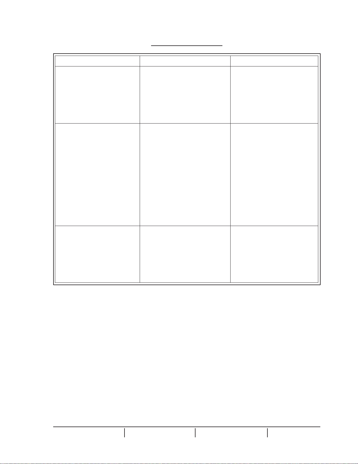
3. TROUBLESHOOTING
PROBLEM
PROBABLE CAUSE
SOLUTION
Empty racks do not move on
the power roller conveyor
The power roller system requires
some amount of load on the
rollers to develop driving force to
rotate with the shaft, which is
driven by the sprocket. The load
on the roller due to the empty
rack may not create enough
driving force.
Convey the fully or partially
loaded racks. This problem is
most common for a new system.
Individual rollers do not turn
Refuse jammed at the ends of
the roller.
Bushings at end of the roller and
the body frame are worn out.
Clean the ends
Inspect the bushings & replace
them. It is recommended to
replace the stainless steel shaft
along with the worn out
bushings.
Generally nylon sprocket and
the shaft wear out at the same
time. Therefore it may be
feasible to replace the shaft,
sprocket and bushing assembly
at the same time.
Start button pushed but system
does not work
Power supply is not available
Fuse in the main control panel
has blown.
Make sure that the power supply
is available to the system.
Replace the fuse. If the fuse
blows again, check the chain
track to make sure that nothing
is struck the chain and causing
the overload to the motor.
Note: If you continue to experience problems, please notify Aerowerks
Aerowerks©2017
Page 11

Toll Free : 888-774-1616
Fax : (905)-363-6998
- 11 -
www.aero-werks.com
4. MODELPRC-POWEREDROLLERCONVEYORPARTS
Aerowerks©2017
Page 12
Toll Free : 888-774-1616
Fax : (905)-363-6998
- 12 -
www.aero-werks.com
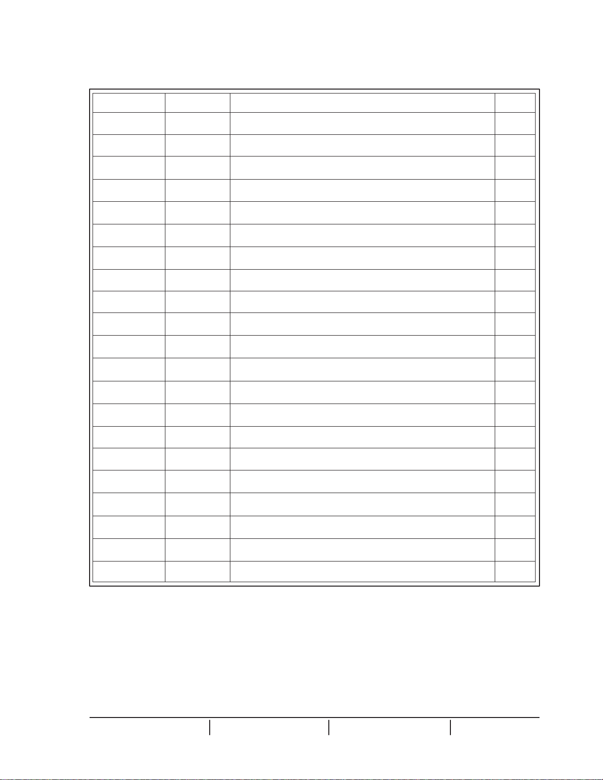
PRC - POWERED ROLLER CONVEYOR PATRS LIST
Item #
Part #
Description
Unit
PRC 1
0082118
Drive housing cover
PRC 2
0082117
Side cover
PRC 3
8117408
Power roller chain #50 S/S
PRC3A
8117404
Power roller chain #50 S/S side bow
PRC 4
8402156
UHMW wear strip
PRC 5
8103205
Nylon sprocket
PRC 6
8102071
Mushroom bushings
PRC 7
8102080
Roller bushings
PRC 8
0081111
S/S roller
PRC 8A
0095202
S/S roller w/bearings
PRC 9
0081112
S/S shaft
PRC 10
0082119
Snub sprocket complete assembly
PRC 11
0081130
S/S tube spacer
PRC 12
8103309
Drive sprocket
PRC 13
----
Gear motor mounting plate & clips w/hardware
PRC 14
8701001
Gear motor
PRC 15
0082130
Gear motor housing
PRC 16
8117462
Chain Link
PRC 17
501315
Power roller curved section
S/S 50B15
8103215
Sprocket
----
810302
Super lube grease (Aerosol)
Aerowerks©2017
Page 13
Toll Free : 888-774-1616
Fax : (905)-363-6998
- 13 -
www.aero-werks.com
5.
WARRANTY FOR MODEL PRC-POWERED ROLLER CONVEYOR
5.1. WARRANTY PERIOD
Aerowerks warrants its products to the original purchaser against any defects in
material and workmanship, under normal use and service for a period of one year
after the date of installation by Aerowerks personnel or an Aerowerks authorized
agent.
5.2. GENERAL
Aerowerks will not cover for damage to electrical/mechanical equipment on conveyors
due to power surges, water damage (due to building plumbing leaks or improper
equipment maintenance) & overload trips under warranty. Aerowerks is not liable for
any faulty installation, damage, mechanical & electrical failure caused by unauthorized
alteration, misuse or abuse of the equipment. Liability or obligation in connection with
the products of Aerowerks other than those covered in this warranty by any other
person’s assumption is not authorized by Aerowerks. This warranty is limited to the
United States and Canada.
HOW TO HANDLE A WARRANTY CALL
Please contact Aerowerks Customer Support Staff at 1-888-774-1616 ext. 0 for all
concerns regarding Aerowerks equipment. Hours of operation are 8:00 am to 4:30
pm EST.
Do not contact Hobart Service: Hobart Service is our authorized service agent and
will only perform warranty service with a valid purchase order and authorization from
Aerowerks. Contacting us will speed up the process of your warranty concern to
minimize your downtime. If you require after hours emergency service please call
Hobart Service. In the event if Hobart Service has scheduled a service call without
prior notification to Aerowerks they must notify Aerowerks and request a valid
purchase order from Aerowerks during our normal business hours before invoicing
Aerowerks.
Please Note: Aerowerks will cover the cost of the service call, overtime charges will
be the customer’s responsibility. The claim must be submitted to Aerowerks
immediately for validation.
5.3. WARRANTY COVERAGE
It is important to follow the proper operation and maintenance procedures outlined in
the service manual, so that the new Aerowerks System will provide you years of
trouble free operation. Failure to follow proper operating and maintenance procedures
will void the warranty of your equipment.
Aerowerks©2017
Page 14

Toll Free : 888-774-1616
Fax : (905)-363-6998
- 14 -
www.aero-werks.com
Please review complete system manual for operation, clean-up and maintenance
procedures.
The obligation of Aerowerks under this warranty is to repair or replace any defects in
the equipment. All the services covered under the warranty will be provided by
Aerowerks during the regular working hours. All claims against this warranty must be
made in writing to Aerowerks. Equipment must be serviced either by technicians of
Aerowerks or agents authorized by Aerowerks. All warranty parts will be shipped to
the client via regular ground transportation.
Powered Roller Conveyor
The following are not covered under this warranty:
Normal wear on parts including sprockets, rollers, shafts, bushings and equipment
damage due to power surges or overload trips. Aerowerks is not liable for any faulty
installation, damage, mechanical & electrical failure caused by unauthorized alteration,
misuse or abuse of the equipment.
Aerowerks©2017
 Loading...