

Aerowerks SBC Service Manual

TABLE OF CONTENTS
INSTALLATION & OPERATING INSTRUCTION MANUAL FOR MODEL SBC –
SLAT BELT CONVEYOR SYSTEM
1. GENERAL INSTALLATION _________________________________________3
1.1. ELECTRICAL FIELD WORK___________________________________________ 3
1.2. BUILDING CONNECTIONS ___________________________________________ 5
1.3. INSTALLATION OF CONVEYOR BELT _________________________________ 5
1.4. INSTALLATION AND REMOVAL OF AEROWERKS SLAT ________________ 5
1.4.1. Installation ________________________________________________________ 5
1.4.2. How to install slats __________________________________________________ 5
1.4.3. Removal __________________________________________________________ 7
2. OPERATION ______________________________________________________7
2.1. SLAT BELT CONVEYOR _____________________________________________ 7
2.2. START AND STOP INSTRUCTIONS ____________________________________ 7
2.2.1. Slat belt wash system ________________________________________________ 8
3. MAINTENANCE ___________________________________________________9
3.1. BEARINGS__________________________________________________________ 9
3.2. CHAIN TAKE UP ____________________________________________________ 9
3.2.1. Slat belt chain ______________________________________________________ 9
3.2.2. Drive chain _______________________________________________________ 10
3.3. DETERGENT PUMP _________________________________________________ 10
3.3.1. Replacing detergent pump ___________________________________________ 11
3.4. DRIVE SHAFT AND DRIVE SPROCKET________________________________ 12
3.5. ELECTRICAL SYSTEM ______________________________________________ 12
3.6. GEAR BOX ________________________________________________________ 13
3.6.1. Replacing gearbox _________________________________________________ 13
3.7. MOTOR ___________________________________________________________ 13
3.7.1. Replacing drive motor ______________________________________________ 13
3.7.2. Replacing drive motor brushes ________________________________________ 14
3.8. RETURN TRACK CORNER GUIDES ___________________________________ 14
3.9. SCR SPEED CONTROLLER __________________________________________ 15
3.10. REPLACING SPEED POTENTIOMETER ________________________________ 15
3.11. SLAT BELT CONVEYOR ____________________________________________ 15
3.11.1. Daily __________________________________________________________ 16
3.11.2. Weekly ________________________________________________________ 16
3.11.3. Monthly _______________________________________________________ 16
3.11.4. Semi-annually___________________________________________________ 17
3.11.5. How to install slats _______________________________________________ 17
1

3.12. SPRAY ARMS ______________________________________________________ 17
3.13. SPROCKETS _______________________________________________________ 18
3.14. WATER MIXING VALVE ____________________________________________ 18
4. TROUBLE SHOOTING ____________________________________________19
4.1. SLAT BELT CONVEYOR ____________________________________________ 19
5. REPLACEMENT PARTS - DRIVE UNIT _____________________________23
6. REPLACEMENT PARTS LIST --- TAIL UNIT ________________________24
7. REPLACEMENT PARTS CONVEYOR TRACKS _____________________25
8. WARRANTY FOR MODEL SBC - SLAT BELT CONVEYOR SYSTEM ___28
8.1. WARRANTY PERIOD _______________________________________________ 28
8.2. WARRANTY COVERAGE____________________________________________ 28
8.3. GENERAL _________________________________________________________ 28
2

INSTALLATION & OPERATING INSTRUCTION MANUAL
FOR MODEL SBC – SLAT BELT CONVEYOR SYSTEM
The following instructions for a Slat Belt Conveyor should be carefully read and followed.
Any deviation will affect the warranty of this machine. The conveyor unit shall be
installed by or under the supervision of Aerowerks or its authorized representatives to
validate the warranty.
NOTE: A "Layout Drawing” representing the overall conveyor system, specific to
this project is included in this manual. Owners and maintenance personnel should
become familiar with this document.
1. GENERAL INSTALLATION
Carefully clean all materials from top and bottom tracks. Set the machine in place and
level in the correct position. Bolt together the drive and tail units. Extreme care shall be
taken to install the return track into the drive tank. The edges of the return track extending
inside the drive unit shall be bent outwards as shown in the figure 1.0
CAUTION: These are the most vital instructions to be followed for the installation
of SBC conveyor system.
• The return track shall be tack welded to the center of the drive unit.
• All return track joints shall be field welded and ground smooth.
• All the field welded top bed joints also shall be ground smooth.
• Place and slide the bed in proper position over the drive unit and fasten down
with the studs and bolts supplied for this purpose.
1.1. ELECTRICAL FIELD WORK
Most of the projects require some electrical fieldwork. The details are included in the
'Layout Drawing'. All the work must be done in accordance with local electrical codes.
Wiring must be run in liquid-tight conduit. Usually the electrical work involves making
connections to the accumulation switches, or auxiliary push buttons. Locate and mount the
pre-wired Main Control Panel housing and make appropriate connections.
3
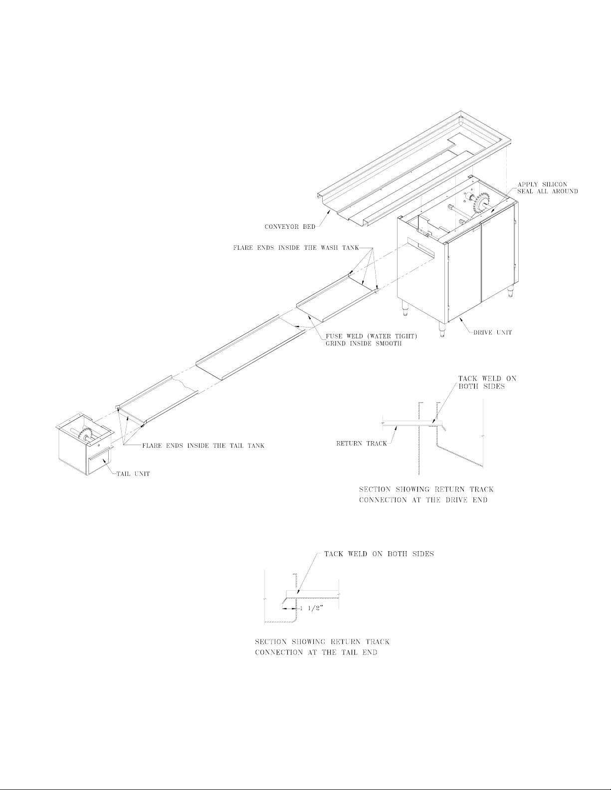
FIELD ASSEMBLY OF CONVEYOR COMPONENTS
Figure 1.0
4

1.2. BUILDING CONNECTIONS
All the plumbing supply, drains as well as electrical connections must be made in
accordance with the applicable local codes. 1-1/2" waste connections are required at the
drive and tail units. 1/2" hot and cold-water connection is required to the “Y” plumbing
fixture located inside the drive unit. An electrical connection is required at the junction
box inside the drive unit for the motor. Check the "Layout drawing" for the specific
requirements of this project.
1.3. INSTALLATION OF CONVEYOR BELT
1. Inspect the return track for any sharp edges or ill-fitting joints and clean them up.
2. Place a 10’ slat belt section on the conveyer track. Please make sure that the arrow
shape of the slats is pointing to the drive end.
3. Feed the slat belt around the drive sprocket and then to the return track.
4. Join a next 10’ slat belt section in the same orientation, using connecting links. Feed
and advance the slat belt in the return track.
5. Continue joining and feeding the slat belt sections till it covers entire return track, tail
unit sprocket and overlaps.
6. Remove the excess length of the slat belt chain and connect the ends. It is important to
allow about 2” belt sag between the drive sprocket and the in feed return track. With
proper sag, the belt will release from the sprockets properly and operate smoothly.
7. Make the field connections and turn on the power.
8. Run the conveyor on a low speed, check all the turns on the top and bottom track as
well as inside the drive and tail unit for quiet operation.
1.4. INSTALLATION AND REMOVAL OF AEROWERKS SLAT
The Aerowerks slat is specially designed for easy installation and removal from the
stainless steel side-bow chain. Once the slats are assembled, the extended pins of the chain
must be completely engaged in the holes provided in the slat. This is usually ensured by a
"clicking" sound during the assembly.
NOTE: Slat will lay flat and straight when properly installed.
1.4.1. INSTALLATION
1.4.2. H
OW TO INSTALL SLATS
There are two ways to install slats on the chain. The first method is outlined below.
Step 1 Lift up the chain and place a ¾” rod or screwdriver handle underneath
the chain.
5
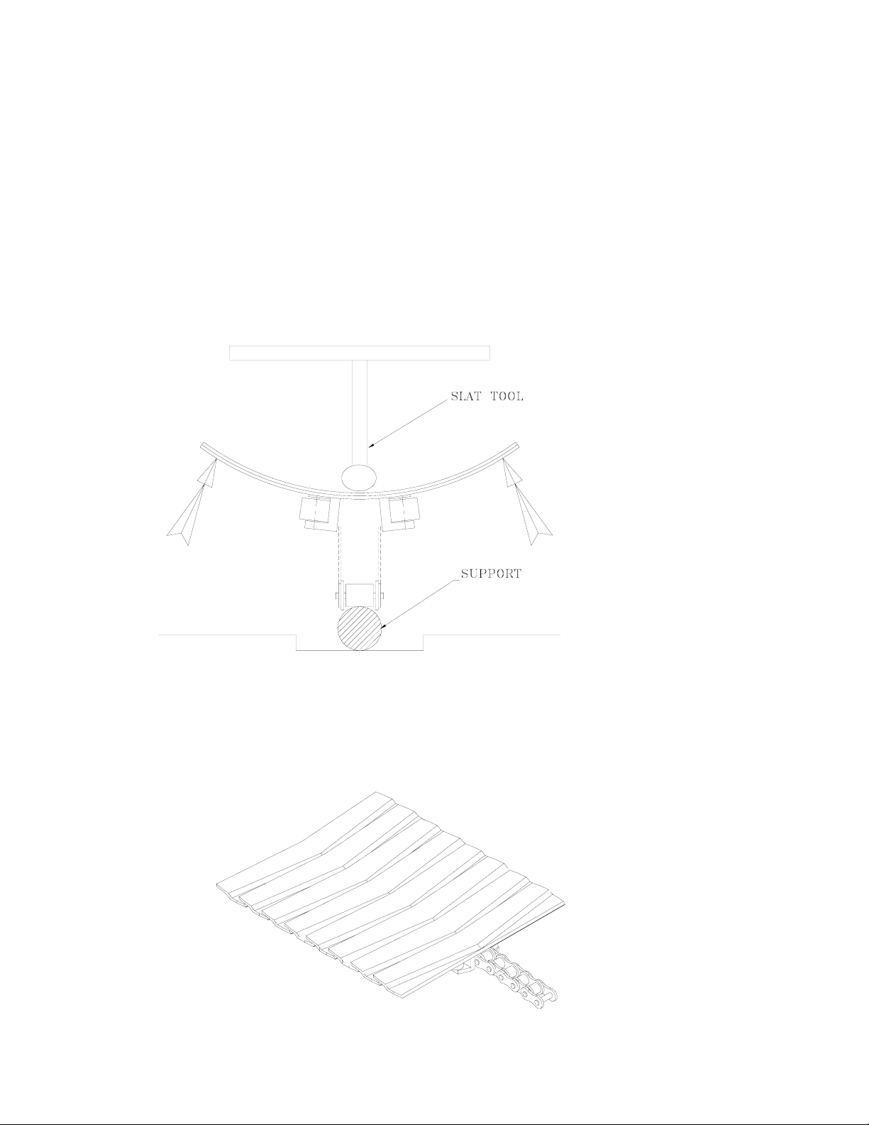
Step 2: Place Slat Tool at the center of the slat as shown below. Use your
fingers to grasp the ends of the slat and arch the slat
Step 3: With the slat arched push onto the chain and engage the pins on the chain
into the holes on the slat. A slight “click” may be heard when the slat is
engaged.
Step 4 Remove the support. If slat is properly installed, it will lay flat and
straight with respect to the other slats.
Figure 2.0
Figure 3.0
6

The second method is easier to accomplish, but may require two people. In this
method the belt is advanced until the empty spot (missing slat) is stopped on the
drive sprocket of the conveyor unit. Then follow steps 2 and 3 as explained in the
previous method.
Note: Under no circumstances shall the slats be hammered. Hammering the slat will
break the plastic lugs that keep the chain locked inside them.
Aerowerks also offers a custom Slat Tool that can be ordered as a spare part. This
tool has been specially designed to ease the installation of new slats.
1.4.3. REMOVAL
In removing the slat from the chain simply place thumbs at the center of the slat and use
other fingers to grasp the ends of the slat to arch as shown in the figure 2. Pull away the
slat once the pins on the chain disengage the holes in the slat lugs.
2. OPERATION
2.1. SLAT BELT CONVEYOR
2.2. START AND STOP INSTRUCTIONS
1. Make sure that all the drive units and tail tanks have the strainers in place.
( if the strainers and doors are not replaced properly, operating the system may result
in flooding and clogging of drains, which will not be covered under warranty)
2. Make sure that the slat belt is sitting properly in the track and belt line is free from any
obstructions such as spoons, knives, forks and napkins, etc.
3. Turn the MAIN DISCONNECT SWITCH located on the main control panel to the
“ON” position.
4. Then push the green ‘START’ button for whichever Slat Belt Conveyor you wish to
start. (The Slat Belt Conveyor can be used as Tray Conveyor, Plate Conveyor or
accumulation Conveyor. Some system may consist of multiple slat belt conveyors).
5. Before shutting down the conveyor push the red ‘STOP’ button. Finally turn the
‘MAIN DISCONNECT SWITCH’ to the ‘OFF’ position.
6. The conveyor stops automatically when a stack of dishes reaches the end and actuates
the limit switch by pushing the flap. The conveyor runs again once dishes are cleared.
The slat belt plate conveyor comes with a limit switch for accumulation purposes as
shown in the figure 4.0
7
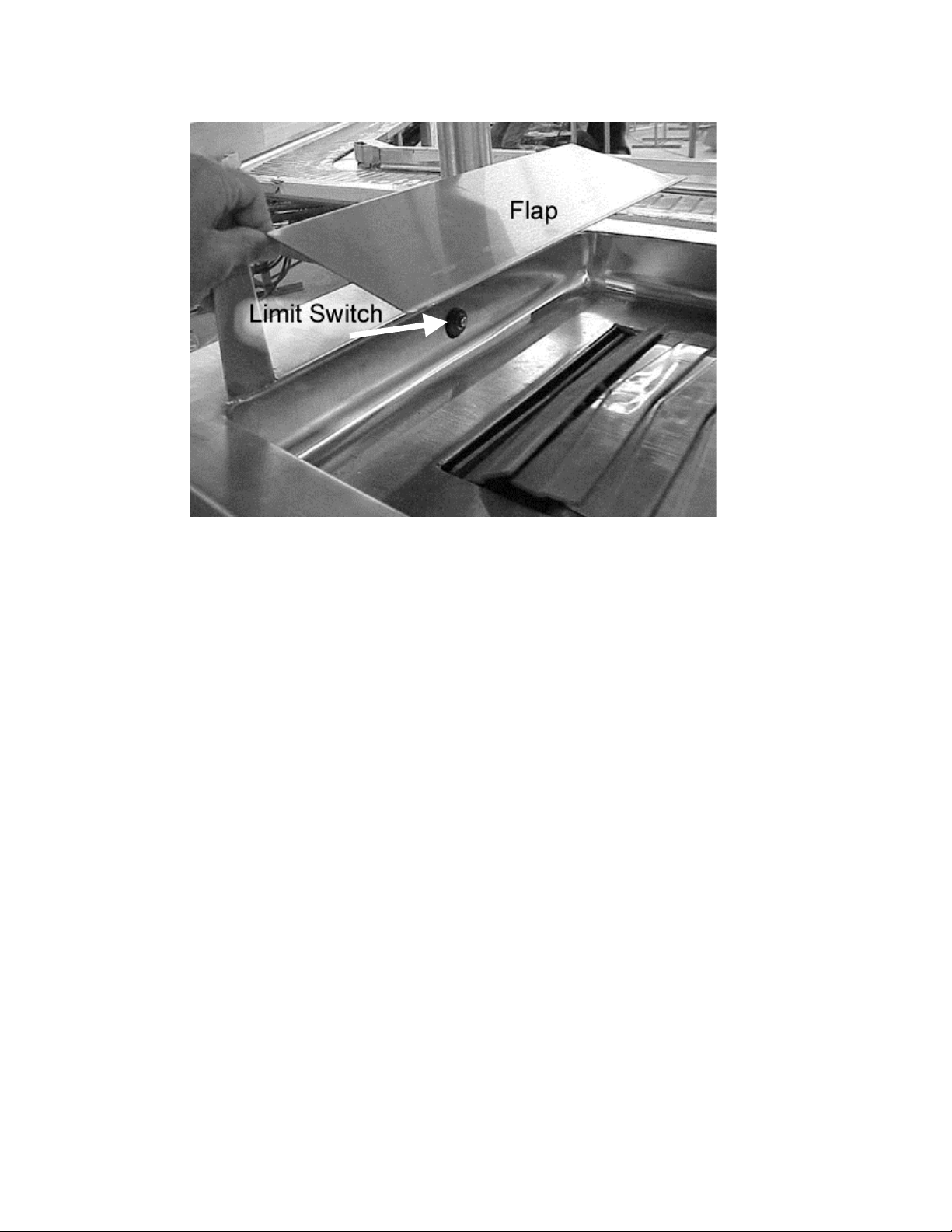
Figure 4.0
2.2.1. S
LAT BELT WASH SYSTEM
1. Turn the Switch to SPRAY & DETERGENT position to start the belt wash system
2. The Detergent Pump is preset for an optimum flow of the detergent and water
mixed solution. The setting can be changed for the desired flow by referring to the
service manual.
3. On some conveyor models LOW DETERGENT warning light on the control panel
glows when the solution tank runs out of the detergent. Fill the detergent to the
solution tank as and when the level drops.
4. To shut down the Wash Belt System, use the selector switch to switch from SPRAY
& DETERGENT to SPRAY for 5 minutes to make sure that the belt is completely
rinsed. Turn off the belt wash. Then bring the speed of the conveyor to zero, Push
the red STOP button and turn the Main Disconnect Switch to OFF.
5. Once the unit is shut off, the daily clean up procedure may begin. No service or
cleaning should be done on the unit when the conveyor is running. For more
information please see section 3.1.1.1.
6. The Main Disconnect switch on the Aerowerks control panel also has a special lock
out feature that disables power to the unit and can be locked so that nobody can
accidentally start the conveyor.
Note: Turn on the belt wash system when the conveyor is running.
8

3. MAINTENANCE
Our Conveyor Systems are built with high quality standards to provide a reliable service
and trouble free operation. The life of the equipment can be extended by regular
maintenance. It is strongly recommended to get the equipment serviced by Aerowerks or its
authorized service agent.
Following are the recommended maintenance schedule. ( A spare part reference sheet is
provided at the end of this manual). Please refer to this list when ordering your parts.
3.1. BEARINGS
The two- (2) 1” flange bearings are located in the drive unit. These bearings shall be
lubricated with Food Grade Grease, once a year, from date of startup.
3.2. CHAIN TAKE UP
3.2.1. S
LAT BELT CHAIN
The slats are attached on a stainless steel slat belt chain. Under normal operating
conditions this chain should never need any replacement. However over a period of time,
the tension in the chain produces permanent stretch and requires an adjustment to reduce
the length.
Follow these steps to reduce the length of the slat belt chain.
Step 1: Remove about 5 slats from the chain near the connecting links.
Step 2: Remove the connecting links to disconnect the chain
Step 3: Pull both ends of the chain together.
Step 4:
Remove the excess stretch in the chain by removing required
number of links. Removal of each link reduces the overall chain
length by 1 ½ “
Step 5: Connect the both ends of the chain using the pin and connecting
links.
Step 6: Run Conveyor and inspect the slat belt for smooth operation. If the
slack is still too excessive, repeat steps 2 through 6.
Note: It is important to allow about 2” belt sag between the drive sprocket
and the in feed return track. With proper sag, the belt will release from the
sprockets properly and operate smoothly
9
 Loading...