

Page 1
Add-on for Microsoft
BroncoBronco
Flight Simulator
Manual
Page 2
Bronco X
Concept Mathijs Kok (Aerosoft)
Models/Textures: Stefan Hoffman (Aerosoft)
XML/ gauges: Finn Jacobsen (Aerosoft) /
Frank Wiesmann (Aerosoft)
Flight mechanics: John Cagle
Project Management: Mathijs Kok (Aerosoft)
Manual, documentation: Finn Jacobsen (Aerosoft),
Mathijs Kok (Aerosoft)
Sounds: William Lennox (Aerosoft)
Images: Nick Churchill
Installer: Andreas Mügge (Aerosoft)
Testing: Several good folks who will
all be getting a free copy
A special thanks to the OV-10 Bronco Association, German Wing, very cool
people (Tony DeBruyn, Thomas Viertbauer, Tom Houquet, Michael Vaeremans,
Peter Junior, Heinz-Dieter Rheinländer, Ela Gedl, Markus Rheinländer) who fly a
very cool aircraft. Without their help this aircraft would not be half as good.
Copyright: © 2012/ Aerosoft GmbH
Airport Paderborn/Lippstadt
D-33142 Bueren, Germany
Tel: +49 (0) 29 55 / 76 03-10
Fax: +49 (0) 29 55 / 76 03-33
E-Mail: info@aerosoft.de
Internet: www.aerosoft.de
www.aerosoft.com
All trademarks and brand names are trademarks or registered of their
respective owners. All rights reserved.
2 3
Aerosoft GmbH 2012
Page 3

BroncoX
Manual
Add-on for
Microsoft Flight Simulator X
Page 4

Bronco X
Content
Introduction ...............................................................6
System Requirements .......................................................... 7
Contact Support ................................................................... 8
Specifications(OV-10A) ........................................................ 9
FSX Limitations and Settings ............................................ 10
Flying the Bronco .....................................................13
The Garrett Turboprop Engine .......................................... 16
Failures ...................................................................... 18
Accumulative Engine Wear ........................................ 19
Electrical System ................................................................ 22
Battery Busses ........................................................... 22
Engineer Station Gauge............................................. 24
Fuel System ........................................................................ 26
Hydraulic Power System ................................................... 27
Oil System .......................................................................... 27
Power Levers/ Condition Levers ....................................... 28
Landing Gear ...................................................................... 29
Nosewheel Steering .................................................. 29
Wheelbrakes/ Parking Brakes ..................................... 29
Flight Control Systems ...................................................... 30
Trims ......................................................................... 30
Wing Flaps ................................................................ 30
Aerosoft GPS Unit .............................................................. 31
Map Mode ................................................................ 31
Direct To Mode .......................................................... 32
Cursor Mode ............................................................. 33
HSI Page ................................................................... 35
Becker BXP 6401 Transponder .......................................... 38
Tacan Receiver .................................................................... 40
Becker AR 4201
Communication Radio ....................................................... 41
Interactive Checklist Gauge .............................................. 42
Panels ................................................................................. 46
Aerosoft GmbH 2012
4 5
Page 5

Main Panel ......................................................................... 47
Right Side Main Panel ....................................................... 48
Left Rear Side Panel ........................................................... 49
Left Forward Side Panel .................................................... 51
Throttle Quadrat ................................................................ 52
Overhead Panel ................................................................. 53
Right Forward Side Panel .................................................. 54
Right Rear Side Panel ........................................................ 55
Right Sidewall Switches .................................................... 56
Checklist ............................................................................. 57
Normal Checklist ....................................................... 57
EMERGENCY CHECKLIST........................................... 68
Appendix A: Landing Pattern ........................................... 79
Appendix B: The Making Of ............................................. 80
Page 6

Bronco X
Introduction
Almost all aircraft designed for a COIN (counter-insurgency) are great
fun to fly. They have to be sturdy and have loads of power to get out
of trouble and they also have got to be agile and easy to fly low to the
ground. So they are all the opposite of airliners that draw straight lines
high in the sky, they feel most at ease when the hug the ground and
pull G. The OV-10 Bronco is perhaps the finest example of this class of
aircraft.
The Bronco has its roots deep in the 1960s when most military aircraft
were getting bigger, more complex and way faster. These aircraft did
not work well in harsh conditions found in jungles and even on carrier
decks. The concept of a rugged close air support aircraft that would
be ideal to operate in limited scale conflicts and operate from improvised airfields was proven by the Cambodia and Vietnam conflicts that
were developing at the time. The North American (later Rockwell)
developed the concept into prototypes that were soon in service with
the U.S. Marines Corps, U.S. Air Force and the U.S. Navy. In Vietnam
the aircraft was introduced in a Forward Air Control role, guiding large
attack aircraft onto targets but soon the Bronco’s went into battle with
a large array of ground attack weapons. Medium bombs, rocket and
gun pods all proven to be effective and even Sidewinders against air
targets were used. To increase loiter time over ‘Indian’ country external
fuel tanks were added. All this additional weight and drag caused the
aircraft to feel underpowered, even though it has ample power when
it is flown without external stores.
The Bronco has a small fuselage but if comfort was not important and
the backseat removed it could carry 5 passengers. In fact the Bronco
was soon used in every possible role. It was one of those aircraft that
seemed to grow in potential over time, and as can be seen with other
aircraft (the A10 Warthog for example) it seems hard to find a modern
replacement. That’s why there are still plans to build a updated version
using the same basic design. When the Bronco was pulled from front
line duty it was still in demand in military and civil roles.
Aerosoft GmbH 2012
6 7
Page 7

Countries like Colombia, Indonesia, Philippines, Thailand, Venezuela,
Lebanon and Germany used them for many tasks including drug
interdiction, firefighting and target tugs. Many are still flying and they
are welcome guests at airshows with their distinct shape and sound.
Our standard version is based on the OV-10B that was last in service in
Germany as a target tug (dragging air targets for other fighters) and
now fly as part of the German Wing of the OV10 Bronco Association
(GWOBA). That organization and especially its founder Tony De Bruyn
and press Officer Markus Rheinländer cannot be thanked enough. Do
visit their website at http://www.germanwing.de/Start.htm.
System Requirements
• Windows XP, Vista, 7 (fully updated)
• Microsoft Flight Simulator FSX (with SP2 or Acceleration Pack)
• Dual Core CPU
• 2 GB RAM internal memory
• 512 MB graphic card
• Adobe Acrobat® Reader 8 minimal to read and print the
manual (1)
(1) Available for free, download at: http://www.adobe.com/prodindex/
acrobat/readstep.html
Page 8

Bronco X
Contact Support
Support for this product is offered by Aerosoft. We prefer to have a
support forum for the simple reason that it is fast and efficient
because customers help customers when we are sleeping.
There are special forums for this product at: http://forum.aerosoft.
com/index.php/forum/474-ov10-bronco/
We feel strongly about support. Buying one of our products gives you
the right to waste our time with questions you feel might be silly. They
are not.
Versions
The Broncos came in various variants:
• OV-10A - Original production version
• OV-10B - German broncos used as target tugs (the Aerosoft
Bronco cockpit is based on this version)
• OV-10C – Export version for Thailand
• OV-10E – Export version for Venezuela
• OV-10F – Export version for Indonesia
• OV-10D – Second generation Bronco with modernized systems
Aerosoft GmbH 2012
8 9
Page 9

Specifications(OV-10A)
Crew: 2
Length: 41 ft 7 in (12.67 m)
Wingspan: 40 ft 0 in (12.19 m)
Height: 15 ft 2 in (4.62 m)
Wing area: 290.95 ft² (27.03 m²)
Empty weight: 6,893 lb (3,127 kg)
Max takeoff weight: 14,444 lb (6,552 kg)
Powerplant: 2 × Garrett T76-G-410/412 turboprop,
715 hp (533 kW) each
Performance
Maximum speed: 281 mph (452 km/h)
Range: 576 mi (927 km)
Service ceiling: 24,000 ft (7,315 m) even though
18.000 ft seemed always more accurate
Armament
Guns: 4 × 7.62x51mm M60C machine guns
Hard points: 5 fuselage and 2 under wing and
provisions to carry combinations of:
Rockets: 7- or 19-tube launchers for 2.75” FFARs or
2- or 4-tube launchers for 5” FFARs
Missiles: AIM-9 Sidewinder (Wing pylons only)
Bombs: Up to 500 lb
Other: SUU-11/A or Mk 4 Mod 0 gun pods
Page 10
Bronco X
FSX Limitations and Settings
Unfortunately FSX has some limitations that are hard to overcome, it
also has some bugs that that are simply not possible to avoid. Some
limitations (like Landing Lights and the complete Electrical System)
have been circumvented by replacing what FSX has to offer and
writing our own code, but some other things are not so easy. We like
to mention them.
Almost all lights are not very solid in FSX. They always seem to wander
around the airframe. Even stranger, this effect depends on where you
are on the globe. We have avoided this effect in some cases by not
using effects but modeled ‘balls’ of light. These are not easy to see at
long distances but look better close up.
The sound is a special problematic area for this project because FSX
does not know this type of engine. When we would have used the
standard turboprop sound the startup would be rather unrealistic as
the propellers would be heard while they would not be moving. So we
are using a combination of FSX sounds and some played by our own
sound module. We even switch off the default FSX sound during
start-up otherwise it would be even more problematic. So don’t worry
if you see the SOUND OFF message appear for a moment.
Aerosoft GmbH 2012
10 11
Page 11
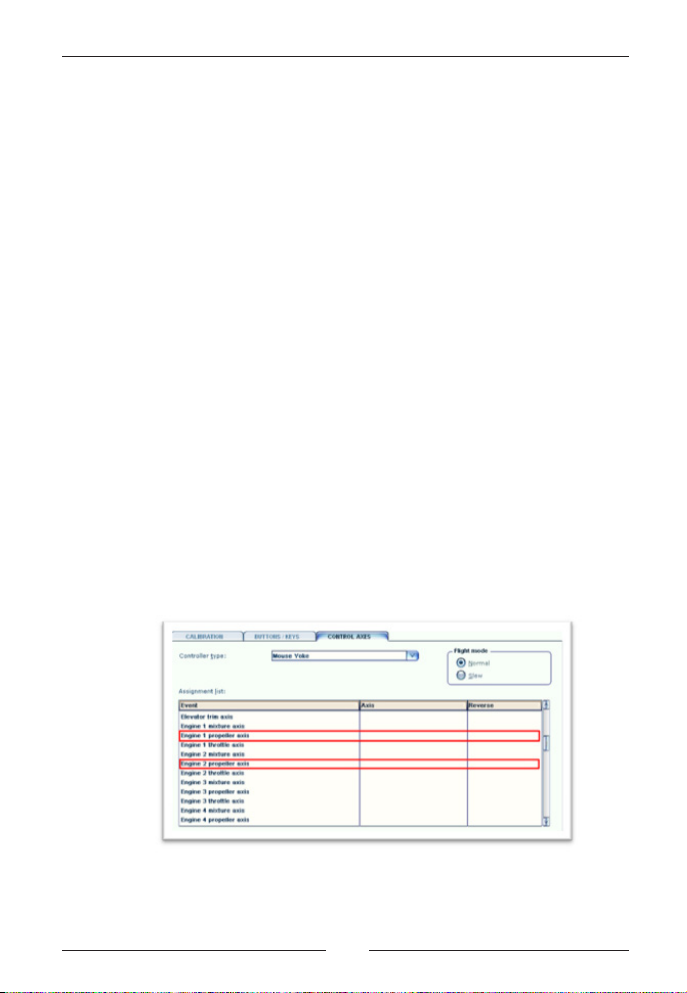
The OV-10 Bronco does use special coding to handle the props and
the Engine 1 propeller axis and Engine 2 propeller axis should be left
unassigned in FSX. If you do have hardware assigned on those axis
leave the levers fully forward when using the Bronco.
We decided not to model the back seat as it really is useless in FSX.
You can’t fly the aircraft from there as visibility is almost zero. Note
that the aircraft is now mostly flown with just the pilot. The Bronco
does not have an Autopilot but we left the standard FSX Autopilot key
commands on so when you do need to make a long flight you can use
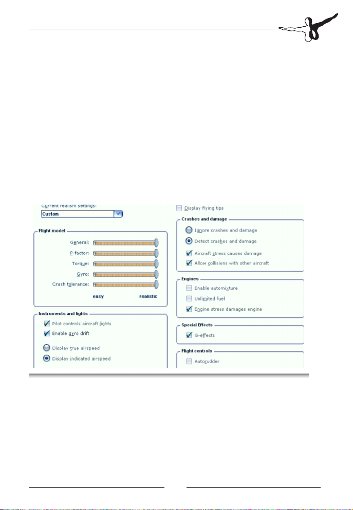
it. We strongly recommend FSX REALISM settings as shown in the
image. If you prefer to fly without rudder activating the Autorudder is
an acceptable option.
Because this aircraft is modeled with detailed system using a nonstandard startup situation could cause some systems to be in an
incorrect initialization state. We provided a startup situation called
Aerosoft - OV10 Bronco that places the aircraft at the airport where it
is normally found (Wevelgem Belgium) with all FSX settings as they
should be. Feel free to change the weather and location but do not
change any of the other settings.
Page 12

Bronco X
To handle some of the more complex systems we need to overwrite
certain parameters in FSX. This causes the standard select engine and
select doors commands to be less reliable. We added a small panel
that can be called up with [SHIFT] + [4] that makes these functions
easy to access.
The Bronco does not have a standard spoiler system so we took advantage of this
to include an invisible spoiler that makes ground maneuvering and STALL landings far more realistic. If you notice that you are not able to reach sufficient speed
in flight (at least 200 knots without any problem) check if there is you have the
spoiler assignment handled by FSUIPC or have it linked to a hardware button. In
the air the code will set the spoilers to retracted a few times every second.
Aerosoft GmbH 2012
12 13
Page 13

Flying the Bronco
You will find that the Bronco is an amazingly easy aircraft to fly; it has
almost no nasty features you should be aware of. There are however a
few things that are special. For starters the very wide speed range, it
has been clocked at 400 knots (okay that is over the 350 knots red
limit and in a dive) and with full flaps it will land at 44 knots (!)
without problems. It will basically feel very happy at any speed
between 100 and 300 knots. If you consider the role of the aircraft it
makes sense. It needs to get somewhere fast and then loiter for as
long as possible. That loitering was often done at low altitudes and
between the trees and hills where the aircraft seems to be happy. As
long as you keep in mind the engines need a bit of time to spool up
(and the aircraft is not loaded up with weapons) you will have ample
power to get out of tricky situation.
The German OV10 Bronco we used as our base model flies at many
airshows and it used to fly this demo in 2010:
1. Take off360° climb
2. High speed pass followed by a 45° steep climb
3. Slow speed pass with landing gear down
4. Top side pass
5. Horizontal 360° turn
6. Bottom pass
7. Wing waggle
8. Stoll Landing
Page 14

Bronco X
Don’t be afraid to pull some G in the Bronco, it loves tight turns. It
also loves steep dives. As one Bronco driver told us:
“…very much a pilot’s aircraft. Named after a type of horse and that
makes a lot of sense. You sit in it like you sit on a horse, in a very high
seating position with great visibility all around and it seems to
understand what you want to do. A good Bronco driver can put her
anywhere he likes in any attitude. It’s a shame they are getting old
now and the pilots have now got more sense than we did. We pulled
stuff you will never see at airshows now and most of my friends
landed after all that. If you lose an engine though, better be prepared
to bail out because things get out of hand real fast.“
Tony de Bruyn, who has to be one of the current Bronco pilots with
the most experience, sent us this when we asked about what it is like
to fly this aircraft:
“Flying the Bronco is like feeling to be on top of the world, such is the
fantastic view all around, the responsiveness on the controls, the
speed range and its versatility. There seem to be no limits in where you
want the aircraft to take you and it does it in such a way that you are
continuously wondering whether the airplane is reading your mind
rather than you making control inputs. It flies with such magnificent
ease that one soon feels very privileged in handling the thoroughbred
and bring the very best out. Some additional personal comments/
thoughts. The people at NAA were probably at the pinnacle of
airplane development at the time when the Bronco was conceived in
the mid 1960’s:
• The engineering is out right brilliant - no doubt building on a
long and highly successful legacy (just to name a few: AT6
Texan, P51 Mustang, B25 Mitchell, F86 Sabre, X15, etc...)
• The flying characteristics are just magnificent; unbelievably well
harmonized and light controls throughout the full speed range
from 70 to 350 KIAS (note: KIAS), very direct and snappy
response to control inputs make it very well liked by everyone
who ever got their hands on it.
Aerosoft GmbH 2012
14 15
Page 15

• Operationally the Bronco is incredibly versatile feeling at home
in and out of any environment - jungle to dessert, unprepared
dirt strips, carrier deck, you name it, it has been there...
• Maintainability; it was designed to be maintained out in the
field with just a standard tool set at hand, no special tools are
required.
• Even when it came to giving the airplane a name, they
absolutely got it right: bronco: A wild or half-tamed horse, esp.
of the western U.S. From Spanish, literally ‘rough, rude.’ The
Bronco is not too large, just as the wild horses out on the
prairies. It’s got a little way of it’s own, but in a good natured
way; you will need to keep it in control - tame it - all the time
but this is easily done.
• It’s got a purposeful rough appearance, some say it’s beautiful
others think differently. It definitely has got CHARACTER and it
shows!
A very likable airplane altogether and I have never come across anyone
who has expressed any dislike or displeasure about the OV10 Bronco,
which is probably also unique and a good indication of its quality.”
If you want to get an idea how the Bronco should be flown, check out
this video: http://player.vimeo.com/video/28244509. It shows the
Bronco in its element, flying low and fast, twisting and turning.
What ever you do, don’t be hung up on charts and speeds. The
Bronco will tell you when it is about to stall (keep an eye on the
airspeed indicator, before the stall happens the buffeting airstream will
make it jitter) and when it wants to fly. One mistake however that is
easy to make is to lose too much speed at landing, although you can
fly at very low speeds it is strongly advised to stay over 100 knots. See
the landing chart that is added at appendix A. Also listen to the
aircraft, you hear the airframe groan when you put G-load on it, the
wind noise will give you good indications on the speed.
Page 16

Bronco X
The Garrett Turboprop Engine
The turboprop model in FSX is poorly modeled, the same is true for
torque and EGT readouts from FSX. Air-starting the engines by wind
milling is not featured by FSX, but through coding around the FSX
“engine”, we managed to correct all these deficiencies.
The turboprop available in FSX is based on the Pratt and Whitney PT6
type of engines. The PT6 is a free turbine engine. This means that the
core engine - the gas producer is a self-sustained gas turbine. The
propeller is driven through a gearbox connected to a separate turbine
placed after the gas producer. This means that the gas producer is
allowed to start and spool up independently of the propeller and it´s
turbine. Since propeller blade pitch angle is controlled via a hydraulic
governor, which uses engine oil pressure, the propeller will move into
feathered position when engine oil pressure is lost or if the condition
lever is moved fully back into the SHUTDOWN and FEATHER position.
A feathered propeller needs a huge amount of torque to overcome the
drag when spinning. Since a free turbine turboprop allows the gas
producer to spool up without turning the prop, sufficient engine oil
pressure will build up to un-feather the propeller.
The turboprop engines used on the Rockwell OV-10A Bronco are the
Garret T-76 types of engines. They are known as single shaft geared
turboprop, in which there is no separate turbine for the propeller. This
means that the propeller is directly linked to the gas producer via the
gearbox. With a feathered propeller, the engine starter will have to
both turn the gas producer as well as the propeller up to speed during
start up. As explained, a feathered propeller needs a lot of torque to
overcome the drag induced when the propeller starts spinning. This is
not desirable. To prevent this, a mechanism called Start latches are
built into the propeller. The start latches locks the propeller blades in
their beta range so with flat pitch position (between full fine and
reverse). In that position the propeller blades produce very little drag,
but also no forward thrust - or at least very little.
Aerosoft GmbH 2012
16 17
Page 17

To engage the start latches, the pilot needs to pull the throttles into
the reverse range right after shutdown of the engines but before Ng
RPM drops below approximately 50%. This will keep the propeller
blades in the beta range enabling the start latches to “snap in” and
lock the blades. To disengage the start latches, the pilot only need to
move the throttle into reverse range after engine startup has occurred
and Ng RPM is above approximately 60%. Throttling up with start
latches engaged will be noticed because of the lack of forward thrust
and little torque readout on the gauges.
In the case where the pilot fails to move the throttles into reverse
range, the propeller will feather, just like on the free turbine types of
engine. In such cases the propellers will need to be un-feathered. This
is done via the Airstart switches. The airstart switches have 3 positions
CRANK, AUTO, ON. AUTO is the normal position and will automatically control fuel and ignition in accordance to the engine RPM sensing
switches. CRANK will turn on a pump called the un-feather pump. This
pump supplies oil pressure to the propeller governor forcing the
propeller blades towards full fine and beta range - no fuel or ignition is
introduced. Crank is somewhat misleading - it won´t crank the engine
by the Starter, but merely points to the fact that in air, the un-feathering of the propeller will cause these to start wind-milling. ON means
that the un-feather pump as well as fuel and ignition is introduced for
an air-start. After un-feathering / air-start the Airstart switch must be
returned to AUTO. Note the Bronco has two additional ignition
switches for continuous ignition.
The description might sound complex, but is actually very straight
forward. For starting the engines on the Bronco follow this procedure:
• Power levers: GROUND IDLE
• Condition levers: SHUT OFF (NOT SHUT OFF & FEATHER)
• Primary DC bus: POWERED (BATT DISC & BATT MAIN
SWITCHES ON OR GRND PWR ON)
Page 18

Bronco X
If propellers not feathered:
• Start switch: ON
• At 10% Ng RPM : CONDITION LEVER NORMAL FLIGHT
If propellers feathered:
• Power levers: MOVE INTO REVERSE RANGE
• Airstart switch: CRANK
• Prop at flat pitch set
Airstart switch: AUTO
• Power Levers: GROUND IDLE
• Start switch: ON
• At 10% Ng RPM: CONDITION LEVER
NORMAL FLIGHT
Failures
The engines in the Aerosoft OV-10 Bronco will fail if they are not
treated with respect. They are very well maintained but they are a few
decades old, so be nice to them. All failures can be switched off in the
checklist configurator.
• Engine flameouts might occur when flying in icing conditions
without having switched on the continuous ignition switches.
• Starter motors will fail if run too long with feathered propellers
due to over torque.
• Continuous torque should be limited to 1875 foot/lb and only
exceeded for short amounts of time. When this limit is
exceeded the chance of a failure increases dramatically. Keep in
mind the overtorque warning light will only be lit at 2200 foot/
lb so do not wait for them to light up.
Aerosoft GmbH 2012
18 19
Page 19

• Another source for engine failure is overheating. To monitor
engine temperatures there is a EGT gauge for each engine.
During startup they show EGT (Exhaust Gas Temperature), but
when Ng (RPM) passes 50% they shift to read TIT (Turbine Inlet
Temperature). EGT is measured with a probe in the exhaust
gas, while TIT is calculated from EGT, since no probe would last
very long at the TIT temperature. The TIT is further altered by
the SRL computer (Single Red-Line) also called the “Pilot Lier”,
since the temperature shown is different from the real TIT.
Under ISA conditions the T76 engines are limited by torque
until approximately 17.000 feet where Max Allowable EGT
normally is reached). With higher OAT this altitude becomes
lower. To be honest, the Bronco is not happy when flown that
high, it’s an aircraft designed to be flown low. Max Allowable
EGT is not a fixed value, but is a function of Ng (RPM), OAT,
Altitude and Airspeed. Using EGT to determine if you are
running the right temperatures is complex and involves many
tables and charts. That’s where TIT with the SRL correction
comes is, Max allowable TIT, compensated by the SRL, is always
approximately 1000 °C , so the pilot only needs to verify that the
needles don´t get higher than that. The TIT Warn lights are also
set to light at 996 °C. Some Broncos (the German OV-10B’s for
example) were later changed to always display EGT, but still have
the TIT warn lights that will light when the temperatures are too
high. Keep an eye on these lights. They are important.
Accumulative Engine Wear
If this option is enabled the engines will start to wear. They will
degrade over time by this schedule:
• 0-80 hours = Excellent
• 80-120 hours = Good
• 120-140 hours = Ok
• 140-160 hours = Poor
• 160 -> hours = INOP (not functional)
Page 20
Bronco X
This schedule only holds true if the engines are operated within their
limits. This means that the engines won´t be over torqued or overheated! If they are being run outside their limits the degradation happens
faster as a function of how much and how long they have been run
above their limits. With increased degradation the engines will start to
run hotter over time until INOP state is reached, then they will stop
running and cannot be started.
The real Bronco has a time between overhaul at 1600 hours (Some
even extended to 3400 hours). Since no flightsimmer ever well reach
that figure this time has been reduced to 1/10 of this i.e 160 hours.
This is still a lot of flight simming time, and since degradation happens
exponentially you won´t see any change before reaching 80 hours.
For those who want to speed up degradation further the option has
been added to decrease this time even further by selecting 2x or 4x
this rate. This option is disabled by default. To enable – click to cycle
between disabled, 1x, 2x & 4x.
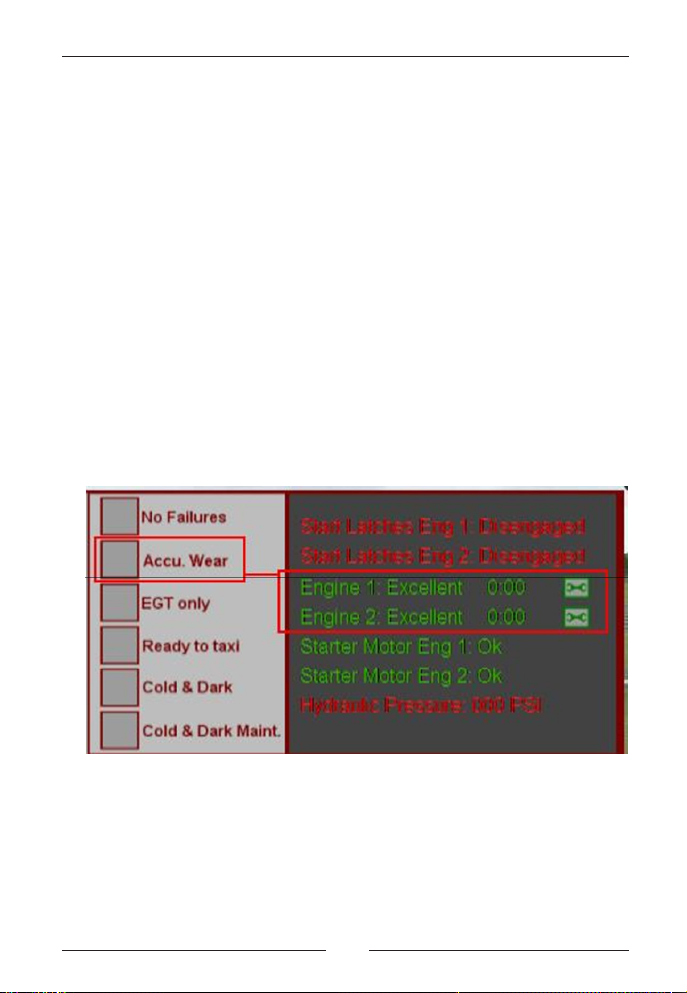
On the above figure the selection box labelled “Accu. Wear” can be
seen. It is disabled. Engine health state can be seen to the right
together with their operating time Hours:Minutes. Clicking on the
small “Wrench” symbol for each engine will overhaul it and reset the
timer. The Wrench symbol will also repair the engine(s) if they have
failed and reset the fire extinguishing system for the affected engine.
20 21
Aerosoft GmbH 2012
Page 21
When the “No failures” checkbox is checked the engines will not stop
running and can still be started, but the EGT gauge will still show the
increased operating temperature due to degradation. When clicking
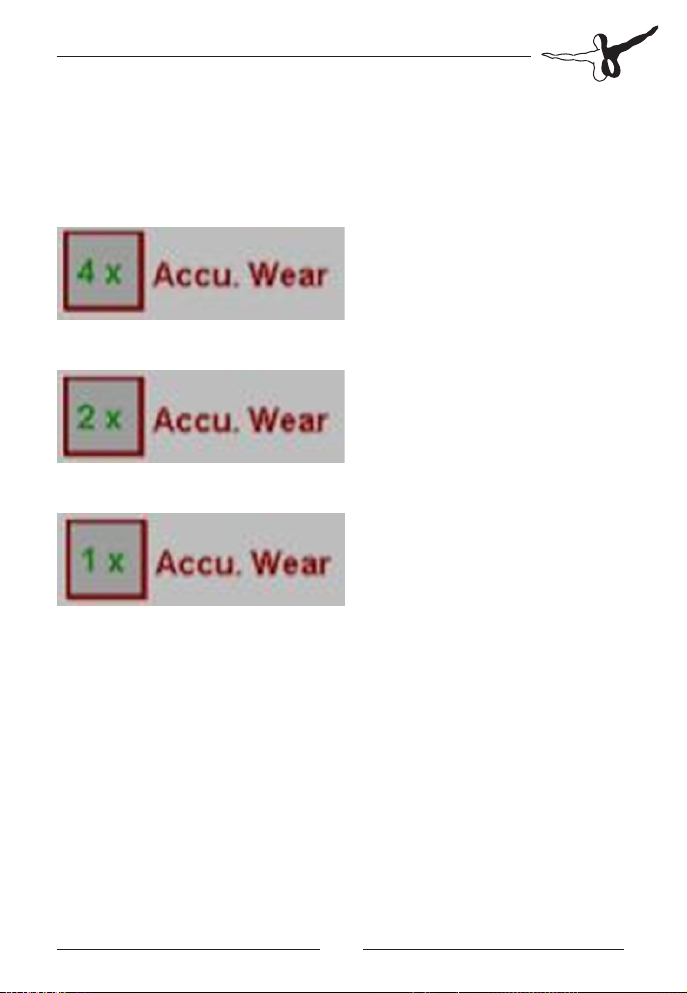
the “Accu. Wear” checkbox the following symbols will appear instead
of a checkmark:
Symbol for normal wear (0-160 hours)
Symbol for 2x wear (0-80 hours)
Symbol for 4x wear (0-40 hours)
When you use the engines correctly you should be able to reach the
160 (or 80 or 40) hours without much problems. Your mechanics will
love you.
Page 22

Bronco X
Electrical System
One of the most important systems of an aircraft is the electrical
system as most parts of an aircraft rely on electrical supply, such as fuel
pumps, hydraulic pump, engine controllers, various instruments and
radios as well as lighting. The electrical system has faithfully been
simulated in the Aerosoft OV-10 Bronco. The default FSX electrical
system has been scrapped and replaced by our custom coded system.
Everything that depends on electricity, down to the smallest light bulb,
will add a load to the system.
The main type of electrical power supply on the Bronco is 24VDC. This
is supplied from the two batteries, the two generators or ground
power. The generators also act as engine starter motors. To manage
the power distribution, the electrical system is divided into several
busses (busbars). This is also done to preserve electrical power in the
event of generator failures. For example the secondary bus, supplying
non-essential systems as lights and radios will be turned off if both
generators fail. The generators, which also act as starter motors, and
can fail if not used right.
Some equipment requires 115VAC. This is made available by converting 24VDC into 115VAC through the inverters. The Bronco has two
inverters, one primary and a backup inverter. Both are powered under
normal conditions though.
Battery Busses
Primary DC bus 24 VDC:
• Startignitionadvisorylight
• Enginerewarnsys
• Fuelboostpumps
• Hydraulicpump
• Gear/Flapindicator
• Alternateaps
• Unfeatherpumps
• Pitotheat
• Windshieldwiper
Aerosoft GmbH 2012
22 23
Page 23

• Smokegenerator
• Trimmotors
• Trimindicator
• Warnandcautionlights
• TurnandSlipindicator
Start Control DC bus 24 VDC:
• Engine1Utilities
• Engine2Utilities
• Engine1Starter
• Engine2Starter
• Engine1ignition
• Engine2ignition
• Fuelshutoffvalves
Secondary DC bus 24 VDC:
• Landinglights
• Taxilights
• Formationlights
• Positionlights
• Anti-collisionlights
• Panellights
• Communicationradio
• Navradio
• ADFradio
• Transponder
Monitored DC bus 24 VDC:
• Yawdamper
Primary AC bus 115 VAC:
• Attitudeindicator
• StandbyAttitudeindicator
• Fuelquantityindicator
• Engine1EGTindicator
• Engine2EGTindicator
Page 24

Bronco X
Monitored AC 1 bus 115 VAC:
• TACAN
• Strikecamera
Monitored AC 2 bus 115 VAC:
• TACAN(Altpwr)
Instrument AC bus 26 VAC:
• VOR/ILSindicator
• DirectionalGyro/VOR/ADFind.
• Markerbeacon
• Engine1torqueindicator
• Engine2torqueindicator
• Oilpressureindicator
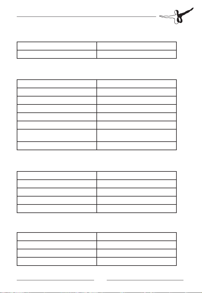
Engineer Station Gauge
During the development of the Bronco it was hard to understand
exactly how the system interacted so the systems coder Finn decided
to make a simple schematic instrument that shows how it works. We
have gotten so used to it we decided to keep it in the released code.
We even decided not to make it look refined so you get an idea of
how we code these complex systems. You can open it with [SHIFT]-[3]
and when you move your mouse over the switches and busses you will
see where you can click. Most switches can be operated (sometimes
with left and right mouse buttons) and when you click on a bus
(vertical thick red line) you will see what’s connected to it. When a bus
or supply “string” is unpowered it is blue, while being red when
powered. Actual voltage and ampere load can be read for each bus as
well as batteries and generators.The best way to see it in action is to
open it, select Cold & Dark and then select ready to taxi. The aircraft
will go through the whole startup sequence and you see the generators and busses come online. When all is running, start disconnecting
things and see how the systems are affected. The real Bronco drivers
would have loved something like this!
Aerosoft GmbH 2012
24 25
Page 25
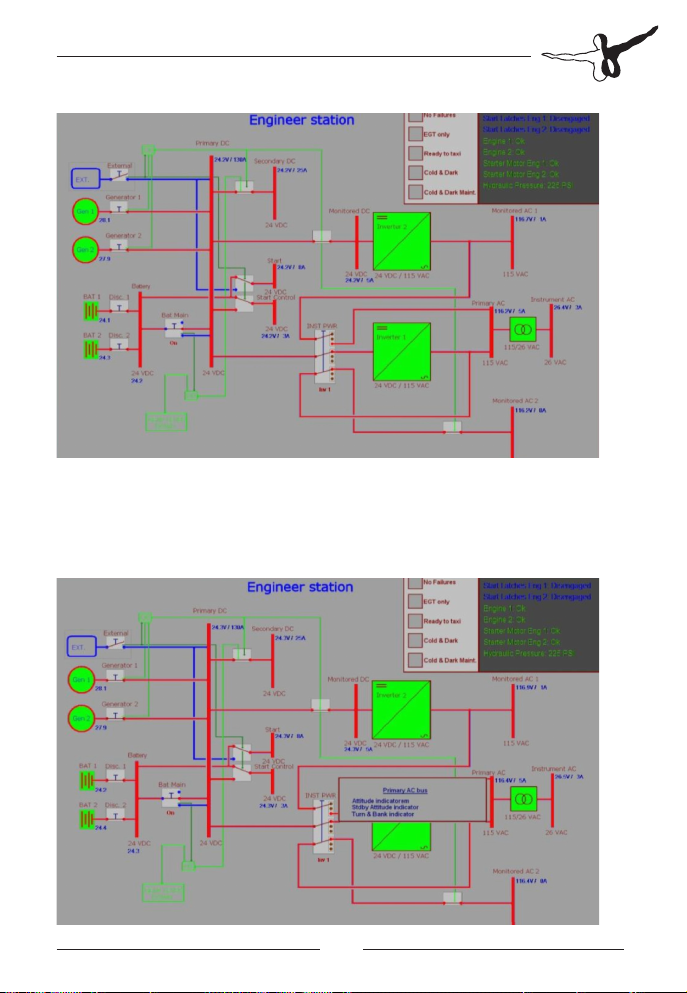
In the upper right corner various engine related items can be checked for their
state. There are also checkboxes for setting aircraft state and user preferences
like found in the Interactive Checklist gauge. When clicking on the various bus
bars a list with the equipment that it supplies will be shown as long as the mouse
button is pressed.
Page 26

Bronco X
Fuel System
The fuel system consists of two inboard, two outboard tanks and one
center tank plus an optional external fuel tank. Fuel from the outboard
tanks flows to the inner tanks and then both inner tanks feed the
center tank all by gravity. From the center tank is pumped by the
engine driven boost to the low/high pressure fuel pumps. These supply
the fuel control units that feed the engines. Fuel from the optional
external tank is pumped with an electrical transfer pump to the centre
tank. The external fuel transfer switch operates the transfer pump at
about 845 pound an hour. When all internal tanks are full and the
transfer pump is used the fuel is dumped via the wing tank vents.
Normally the transfer pump is started when the wing tanks are
partially emptied and then used for half an hour. Do not forget to
switch it off, there is no indication about the quantity of fuel in the
external tank!
CAUTION: As part of the system uses gravity it has only limited
inverted capacity.
The fuel quantity indicator indicates the weight of the fuel in pounds x
100 in part of the fuel tanks depending on the setting of the fuel
gauge select switch. In the FEED position it shows the weight of the
fuel in the centre feed tank. At INT setting the weight of the fuel in
the internal wing tanks is shown Note the 230 gallon external tank
does NOT have any indication so the EXT setting will show zero., the
EXT setting on the fuel gauge does not function with this tank. The
fuel gauge test button will rotate the needle fully clockwise and
counter clockwise to indicate full freedom of movement.
TANK CAPACITY USABLE
GALLONS POUNDS GALLONS POUNDS
WING OUTBOARD 75.3 489 72.4 471
WING INBOARD 134.5 874 130.6 849
CENTER / FEED 37.1 241 36.0 234
EXTERNAL 230 1494 220 1427
TOTAL 476.9 3098 459 2981
Aerosoft GmbH 2012
26 27
Page 27

The FUEL EMERGENCY SHUT-OFF switches cut the fuel flow (and the
fire T-handles) cut all fuel flow to an engine. The engine might operate
for up to a minute on the fuel remaining in the feed lines.
The FUEL LOW caution light illuminates when the centre tank holds
less than 220 pounds. The FUEL FEED warning light will illuminate
when there is less the 50 pound left in the centre tank.
Hydraulic Power System
Hydraulic power is used to power the landing gear, nose wheel
steering and the flaps. It is supplied on demand by the electrical
hydraulic pump. The pump does not provide enough pressure to
operate flaps and gear at the same time at normal rate.
CAUTION: The hydraulic pump needs a 3 minute cool down period
after extensive use (5 minutes of nosewheel steering or three consecutive gear or flap cycles.
A green hydraulic indicator light on the center pedestal will be lit
when the hydraulic pump is activated. An amber warning light
illuminates when pressure is too low for normal operation.
Oil System
Each engine has its own independent dry sump oil system. The oil
system will provide engine lubrication, provide pressure for the
propeller control system and will serve as an additional cooling system
using a ram-air cooler. When the gear is extended the oil cooler doors
are mechanically opened to provide greater cooling capacity during
ground operations.
Page 28

Bronco X
Power Levers/ Condition Levers
The power levers control the thrust output of the engines and are
marked into 4 sections:
• FULL REVERSE: provide maximum reverse thrust. Selection of
reversed thrust in flight is prevented by a switch linked to the
gear. Only when the gear is compressed can reverse be
selected.
• GROUND START: give minimal torque at idle RPM because the
propeller will be set flat pitch position.
• FLIGHT IDLE: sets the engine and propeller to inflight minimum
fuel flow and torque.
• MILITARY: provides maximum torque.
The condition levers control the fuel flow to the engines and are
marked in 4 sections:
• FEATHER AND FUEL SHUT-OFF (normally referred to as FEATH-
ER): will feather the propellers and cut the fuel to the engine.
• FUEL SHUT-OFF: fuel is shut off but the propeller control
systems stay pressurized and propellers will NOT feather.
• NORMAL FLIGHT: open fuel flow to the engines and sets
minimal engine RPM (on ground 60%, inflight 70%).
• T.O./LAND: open fuel flow to the engine and sets minimal
engine RPM (on ground 94%, inflight 96%). These higher
settings allow the rapid response to commands given via the
power levers.
CAUTION: if the condition lever is set to Normal Flight with the engine
not running fuel WILL be injected into the combustion chambers. This
can result in an engine fire when the engine is hot!
Propeller control is automated and controlled as a function of the
power levers and condition levers.
Aerosoft GmbH 2012
28 29
Page 29

Landing Gear
The tricycle-type landing gear of the OV-10 Bronco is hydraulically
operated with the main gear retracting backwards and the nose gear
forward. When on the ground the Ground Safety Switch will deactivate the pitot heater, stall warning, and store emergency release
systems. IFF hold feature, nose wheel steering will be activated.
The landing gear unsafe light will be illuminated if the gear is not
locked in the position of the gear handle. The landing gear position
indicator (integrated with the flaps position indicator) shows the
position of the gear. A red wheels warning light will warn the pilot of
a possible unsafe gear position when the gear is not extended and the
power levers are retarded, engine condition lever is at T.O./LAND and
the flaps are extended 30 degrees or more. An audible warning horn
will sound when the wheels warning light is illuminated.
CAUTION: There is NO protection against retraction of the gear using
a ground safety switch. The gear WILL retract when the gear lever is
operated on the ground and the aircraft is powered up.
Nosewheel Steering
The nosewheel can move 55 degrees left or right using a hydraulic
nose wheel steer-damping system. As soon as the landing gear carries
any weight the nose wheel steering is operational. In the real Bronco
the pilot has to keep a button on the stick pressed, this is not needed
in the simulated version.
Wheelbrakes/ Parking Brakes
The wheel brakes are operated by a separate manually operated
hydraulic system on each wheel. Using the rudder pedals the pilot can
apply the brakes on each wheel separately. When the park brake
handle is pulled and when the brakes are applied the pressure is
trapped in the system. To release parking brakes the pilot just needs to
apply the brakes
Page 30

Bronco X
Flight Control Systems
The elevator and aileron/spoiler are operated by a balanced mechanical
system using boost tabs. The rudders are mechanically linked directly
to the rudder pedals. Trim surfaces are moved by electrically operated
trim bungees.
• Pitch is controlled with a horizontal stabilizer and tab-boosted
elevator.
• Yaw is controlled by two vertical stabilizers, twin rudders and a
yaw damping system. The yaw damper, powered by the d-c
bus, prevents unwanted tail oscillations and is operated with a
three position switch. ON, OFF, TEST. In test mode the deactivation of the systems on the ground is bypassed for ground tests.
• Roll control uses ailerons and is augmented by 4 spoiler plates
inn each wing. These spoilers rotate upwards and create
additional drag and remove lift that will lower the wing.
The control stick includes a roll/pitch trim switch, the nose wheel
steering button, bomb release button and gun trigger. None of these
are functional in the simulated model as they are near impossible to
use in the simulator.
Trims
The flaps / trim panel hold the controls for aileron, elevator and rudder
trim. When trims are in neutral green, press -to-test, lights will be
illuminated.
Wing Flaps
There are two slotted wing flap sections on each wing, normally
operated by hydraulic power, and an electrical backup system is
available. The flaps are controlled by the flap handle and can be set to
any position between 0 degrees and 40 degrees. This is not possible in
FSX and therefore we decided to default to 0, 20 and 40 degrees. The
flaps position Indicator will show the flaps setting and movement.
Aerosoft GmbH 2012
30 31
Page 31

Aerosoft GPS Unit
The GPS instrument has its own internal battery so it can be used
when the Master switch is still off. It’s charged by the Primary DC
electrical bus when the Battery master switch is on. To turn the GPS
on, press the button with the red logo and the start-up screen will be
displayed.
CAUTION: The framerate of the sim is affected by the amount of
details shown!
Map Mode
After initialization the GPS will be in Map Mode showing an aircraft
symbol in the centre of a map. North is always up. In the four corners
of the display, current ground speed, distance to next waypoint,
estimated time to next waypoint and a pointer depicting relative
bearing to the next waypoint are shown. If the pointer points up, the
aircraft is heading straight towards the next waypoint.
Page 32

Bronco X
Use the IN / OUT buttons to zoom the map in or out. The GPS can
show Airports, VOR’s, NDB’s, Intersections and Airspace boundaries. To
toggle the display of these items press the MENU button and use the
UP / DOWN cursor key (the large button) to highlight the Class
(Airport, VORs, NDBs, Intersection or Airspace). Use the LEFT / RIGHT
cursor key to toggle the display of these items. Use the QUIT button to
return to the MAP page.
Standard FSX flight plans can be loaded via the normal FSX dialog and
will be automatically displayed on the MAP page.
Direct To Mode
Using the GOTO button will allow the input of a DIRECT TO location.
Use the UP / DOWN cursor keys to change the character on the
blinking field. Use the LEFT / RIGHT cursor key to move to the next or
previous field. Enter an ICAO identifier for airport, VOR or NDB.
Aerosoft GmbH 2012
32 33
Page 33

NOTE: Intersections are not supported in the GOTO mode.
Once an identifier is recognized, it will show facility name and nearby city – if
possible. Press ENTER and the GPS will return to the Map mode with the flight
plan leg from the current aircraft position to the selected identifier. As everywhere using the QUIT button will halt the action and return to the MAP screen.
Cursor Mode
Another option to make a DIRECT-TO flight plan, is with the help of
the “Cursor Mode”. When the GPS is in map mode, pressing either
the UP / DOWN / LEFT or RIGHT cursor key, will put the GPS into
“Cursor mode”. A small cursor (blinking circle) will appear instead of
the aircraft symbol. Using the cursor keys the circle can be moved on
the map and the map will centre on the cursor position. A line will be
drawn from the current aircraft position to the cursor.
Page 34

Bronco X
Press ENTER to select the cursor position as a Direct-To flight plan. If
the ENTER button is not pressed within a few seconds or by pressing
QUIT, cursor mode will be suspended and the GPS will return to Map
mode. By using the cursor mode any global position can be selected as
a waypoint. This is the easiest way to make a very simple flight plan,
certainly if the desired waypoint isn´t too far away. In cursor mode
finer adjustments can be made by zooming in on the map first.
Nearest Station
Using the NRST button will open
the NEAREST STATION list and the
LEFT / RIGHT cursor keys will
change between Airports, VORs,
NDBs and Intersections. Use the
UP / DOWN cursor keys to
highlight an identifier and press
ENTER to select it as DIRECT-TO, or
press QUIT to cancel the selection.
Aerosoft GmbH 2012
34 35
Page 35

HSI Page
Pressing the ENTER key while being in Map mode will bring up the HSI
page. The HSI page shows:
• Compass rose, showing ground track, which is the true track
over ground, taking crosswinds and sideslip into account. It
does NOT show magnetic nor true heading, like a normal gyro
based HSI.
• Course Needle, showing the active flight plan leg bearing.
• Course deviation indicator bar (middle part of the Course
needle), showing the cross track error. Each dot represents 1
nautical mile.
• TO/FROM flag showing the position relative from the active
flight plan leg.
Right part of the screen shows Ground speed, Distance to next
waypoint, Ground track (same as Compass rose) and next waypoint
bearing.
Page 36

Bronco X
If the Ground track value and the Bearing value are equal, this
indicates that the aircraft is heading straight towards the next
waypoint, but not necessarily following the flight plan leg.
HSI Samples:
On track direct towards the active waypoint, TO / FROM flag shows
TO:
Correct heading but 3 miles to the left of the flight plan leg:
Aerosoft GmbH 2012
36 37
Page 37

Still 3 miles left of the flight plan leg, but on an intercept heading of 40°:
Flight plan leg behind the aircraft, note the TO/FROM flag has changed
to FROM:
Page 38

Bronco X
Becker BXP 6401 Transponder
The Becker BXP 6401 transponder is a Mode
S transponder which enables ATC to locate,
identify and track the aircraft by responding
to ATC radar interrogations. In Mode S it will
conduct altitude reporting, used by other aircrafts TCAS systems for collision warnings.
Remember to turn the Transponder to STDBY after landing when leaving the runway.
The transponder is turned on by rotating the
left knob to STDBY. In STDBY mode the transponder will be on, but it will not respond to
ATC interrogations. STDBY is normally used
until the aircraft is ready for runway line-up.
There is a short self-test on start up. Turning
the knob to ON will make the transponder
start to respond, but without altitude reporting. The blinking R symbol, indicating that
the unit responds. When the knob is at either STDBY or ON the bottom line will show
the aircraft identification number.
Turning the knob to ALT will make the transponder respond with altitude reporting
when inquired. Current flight level will be
displayed. Flight level is altitude in 100th of
feet with the standard setting at 1013 mb.
(1013,2 hpa)
To change the transponder code left click on
the right button and the first digit will start
to blink. Use the mouse wheel to change the
value. Left click the right button again and
the next digit will blink. Left click the right
button when the last digit has been set.
When all digits have not been set, the transponder code will NOT be changed. Press the
VFR button to set the transponder code to
the normal European VFR transponder code,
7000.
Aerosoft GmbH 2012
38 39
Page 39

These are standard codes, otherwise set to the squawk code assigned by FSX’s
ATC:
• 0000: Military intercept code mode C or other SSR failure.
• 0033: Parachute dropping in progress (UK).
• 0041 to 0057: In Belgium assigned for VFR traffic under Flight
Information Services
• 0100: In Australia: flights operating at aerodromes
• 1000: Instrument Flight Rules (IFR) flight below 18,000’ when
no other code has been assigned (Canada). Non-discrete mode
A code reserved use in Mode S radar / ADS-B environment
where the aircraft identification will be used to correlate the
flight plan instead of the mode A code.
• 1200: Visual flight rules (VFR) flight, this is the standard
squawk code used in North American airspace when no other
has been assigned. In Australia civil VFR flights in class E or G
airspace.
• 1201: Visual flight rules (VFR) glider flight, this is the standard
squawk code used in United States airspace for transponder
equipped gliders when no other has been assigned.
• 1400: VFR flight above 12,500’ASL when no other code has
been assigned (Canada).
• 2000: The code to be squawked when entering a secondary
surveillance radar (SSR) area from a non-SSR area used as
Uncontrolled IFR flight squawk code in ICAO countries. In
Canada for uncontrolled IFR at or above 18,000. In Australia:
civil IFR flights in Class G airspace.
• 2100: Australia: Ground testing by aircraft maintenance staff.
• 3000: Australia: Civil flights in classes A, C and D airspace, or
IFR flights in Class E airspace.
• 4000: Aircraft on a VFR Military Training Route or requiring
frequent or rapid changes in altitude (US).
Page 40

Bronco X
• 4400 to 4477: Reserved for use by SR-71, YF-12, U-2 and
B-57, pressure suit flights, and aircraft operations above FL600
(USA only).
• 5000: Aircraft in Military Operations.
• 6000: Australia: Military flights in Class G airspace.
• 7000: VFR standard squawk code when no other code has
been assigned (ICAO). UK: this code does not imply VFR; 7000
is used as a general squawk.
• 7001: Sudden military climb out from low-level operations (UK)
• 7004: Aerobatic and display code in some countries.
• 7010: VFR circuit traffic code in the UK.
• 707X: Paradrop activities in France (7070, 7071, 7072...).
• 7615: Australia: civil flights engaged in littoral surveillance.
• 7777: Military interception Emergency codes:
• 7500: Unlawful Interference i.e., Aircraft hijacking (“seven fife,
man with knife”)
• 7600: Lost Communications.
• 7700: General Emergency (“seven, seven, goes to heaven”)
Tacan Receiver
TACAN is a VOR like navigation
system that uses transmitters
that are mainly placed on or
close to military airfields. Where
you tune a VOR using a
frequency, a TACAN is identified by a channel.
Aerosoft GmbH 2012
40 41
Page 41

The navigation database of FSX is not fully accurate or complete in
regards to TACAN, for some countries all stations seem to be there, in
some other countries there are none. You will find them on your
charts marked with something like CH41X.
Setting the channel is done with the rotary control on the front and the
larger rotary control hiding behind the front plate. Just move your mouse
to the edge of the instrument and you will find the click zone. The smaller
rotary control is used to power the radio on. In any setting except OFF the
radio is activated. The volume control toggles the audio ident.
Becker AR 4201
Communication Radio
The Becker AR 4201 Coms radio is a
basic two way radio for voice communication. It is turned on with the ON/OFF/
VOL knob and will display a test pattern
when started. The upper (large) digits
show the active frequency, while the
lower (smaller) show the standby
frequency. Turning the lower right knob
will change the frequency number
before the decimal sign, while turning
the right upper knob changes the
numbers after the decimal sign. To
swap the standby frequency with the
active, press the swap button (double
arrow button). Pressing the mode
button (MDE) will display the supply
voltage instead of the standby frequency. In this mode the swap button will
toggle the display of Supply voltage,
Outside temperature in °C and Outside
temperature in °F.
Coms radio is seen as COMS 2 in FSX.
The Becker AR 4201
Page 42

Bronco X
Interactive Checklist Gauge
The Aerosoft Bronco X comes equipped with a highly innovative
interactive checklist gauge. The checklist can be opened with [SHIFT] +
[2].
When opened the left page has options for configuring the Bronco
systems and to select prefabricated settings of all aircraft systems. The
upper three “radio” buttons are for setting up the panel state.
• Cold & Dark Normal state: engines are shut down the panels
reflects how a pilot normally will find it for the first flight of the
day.
• Cold & Dark Maintenance State: engines are shut down,
propellers are feathered and generators, fuel shut off valves
and battery disconnect switches are off.
• Ready for Taxi state: engines are running and all systems are
ready for taxi
The lower three check boxes are for setting your preferences.
• EGT gauges showing EGT only: will make the EGT gauge
display EGT and not shift to TiT. Please refer to the chapters on
the engine to understand the difference.
• Play sounds for checklist items: will disable the voice over in the
checklist.
• No failures: will disable all failures that are not standard FSX
failures.
The next pages contain the actual checklists.
Aerosoft GmbH 2012
42 43
Page 43

Click the checklist header (like “COCKPIT CHECK”) and a red checkmark will indicate that the checklist has been started, but not finished
correctly yet. Now click each checklist item and a checkmark will
indicate whether it is set correctly or not. If it has been set correctly a
green checkmark will be shown and a voice will also confirm the item
is checked (or the action performed) and the item is completed. If the
checkmark is red you have two options. Either you can manually
correct the issue or right click the checklist item to have it done for
you. This is especially useful if you have not yet fully mastered the
aircraft and find it hard to find all the switches.
The moment the checklist has been completed the checkmark at the
top will turn green and the voice will tell you the checklist is completed. If you like to start over, use the CLEAR CHECKLIST option.
Page 44

Bronco X
It is possible to go from a cold and dark aircraft to a fully configured,
ready for taxi with engines running state by just right clicking on the
checklist items!
A few additional comments;
• Because some systems are mentioned more than one time in
the checklist it could be a system that is set to ON in one
location and has to be switched OFF further in the checklist.
The first occurrence of those conflicting states will then be
shown in grey instead of green or red.
• The checkmark might blink between red and green when a
control is in the progress of being set
• Where right click options are not possible (like throttle control,
setting of certain speeds etc) the checkmark turns green when
correct settings are detected.
Aerosoft GmbH 2012
44 45
Page 45

• Where there are Left engine / Right engine controls, You will
see a selector at the top of the Checklist section labeled L / R.
CAUTION: The “Unfeathering Propellers” and “Engine Motoring”
should only be executed when required.
The last part of the checklist contains the emergency checklist. This
works exactly like the normal checklist, but don´t have voice overs.
Page 46

Bronco X
Panels
The cockpit of the OV-10 Bronco is rather strange. It’s rather cramped
in the lower sections with all gauges and controls seemingly randomly
placed very close together and above that all is a very roomy glass
section with near perfect visibility. In its role as reconnoiter and spotter
aircraft this visibility was very usable, but it also means that you will
have to look down to see the panel and instruments. As the aircraft is
intended for VFR flights this is not problematic. In FSX it is a bit of a
problem for people who do not use a tracking system that pans the
view around as you move your head. When needed zoom out a bit [-]
and lower the seat [CONTR] + [ENTER].
Aerosoft GmbH 2012
46 47
Page 47

Main Panel
1. Left battery Hot warning light
2. Left over torque warning light
3. Left TiT/EGT high warning light
4. Gyro VOR needle / ILS source selector switch VOR / TACAN
5. Left & Right Continuous ignition switches
6. Standby artificial horizon
7. G-meter
8. Clock / stopwatch
9. Wheel up warning light
10. Alternate TACAN power switch
11. Fire detector / warning lights test switch
12. ADF radio
13. Landing gear lever
14. Landing gear and flaps indicator
15. Elevator trim indicator
Page 48

Bronco X
16. Rudder trim neutral light
17. Aileron trim neutral light
18. Airspeed indicator
19. Altimeter
20. Artificial horizon
21. Gyro compass with VOR/TACAN & ADF needle
22. TACAN radio
Right Side Main Panel
1. Right TiT/EGT high warning light
2. Right over torque warning light
3. Right battery hot warning light
4. Fire extinguisher
5. Fire handles
6. Turn & Bank indicator
7. Vertical speed indicator
Aerosoft GmbH 2012
48 49
Page 49

8. ILS gauge
9. Engine torque indicators
10. Turbine RPM (Ng)
11. TiT/EGT indicators
12. Oil pressure indicator
13. Fuel quantity indicator
14. Fuel qty indicator selector switch
15. External fuel transfer switch
16. Emergency fuel shut off switches
Left Rear Side Panel
1. COM radios transmit select (VHF1 / VHF2)
2. ADF ident sound to speaker
3. COM1 (VHF1) sound to speaker
Page 50

Bronco X
4. COM2 (VHF2) sound to speaker
5. VOR ident (NAV1) sound to speaker
6. External light / Landing light switch
7. Flaps lever
8. Aileron trim / Alternate elevator trim switch
9. Alternate trim select
10. Alternate rudder trim switch
11. Normal rudder trim switch
12. Alternate flaps setting switch
13. Yaw damper
14. Voltmeter / Generator 1 or 2 ampere meter
15. Outside air temperature indicator
Aerosoft GmbH 2012
50 51
Page 51

Left Forward Side Panel
1. Ignition and unfeather switches
2. Starter switches
3. Generator switches
4. Instrument power switch (Inverters)
5. Battery switch
6. Parking brake lever
Page 52

Bronco X
Throttle Quadrat
1. Power levers
2. Condition levers
3. Friction lock for power and condition levers
(move forward to lock)
Aerosoft GmbH 2012
52 53
Page 53

Overhead Panel
1. Whiskey compass
2. Smoke generator switch
3. Camera power switch
4. Camera power on light
5. End of film warning light
6. Film select switch
7. Gun sight dimmer
Page 54

Bronco X
Right Forward Side Panel
1. Pitot heat switch
2. Cockpit defroster
3. Cockpit temperature adjustment
4. Ram air adjustment
5. Windscreen wiper power switch
6. Windscreen wiper speed switch
7. Anti collision lights
8. Formation lights
9. Wing and tail lights (position lights)
10. IFF/Transponder reply light
11. IFF/Transponder test light
12. IFF/Transponder mode selector
13. IFF/Transponder code and selectors
14. Batteries disconnect switches
Aerosoft GmbH 2012
54 55
Page 55

Right Rear Side Panel
1. Gyro compass drift index
2. Gyrocompass source
3. Gyro compass alignment knob
4. Marker beacon ident sound switch
5. Marker beacon Hi/Lo selector switch
6. Marker beacon power/test switch
7. COM1 radio frequency
8. COM1 radio power switch (Lower knob)
9. COM1 radio whole Mhz selector (Upper knob)
10. COM1 radio fractional Mhz selector
11. NAV1radio frequency
Page 56

Bronco X
12. NAV1 radio power switch (Lower knob)
13. NAV1 radio whole Mhz selector
14. NAV1 radio ident switch
15. NAV1 radio fractional Mhz selector
16. “Becker” COM2 radio
17. “Becker” Transponder 2
18. Panel lights
Right Sidewall Switches
1. Bleed-air switches
2. Generator 1 & 2 ampere meter selector switch
3. Canopy open
Aerosoft GmbH 2012
56 57
Page 57

Checklist
The following checklists are taken directly from the real aircraft as
flown right now. Please note that the checklist gauge build into the
aircraft is much easier and much more powerful than this simple list.
In the checklist the sections that have no function in FSX are shown as
light grey. Just skip those.
Normal Checklist
SAFETY CHECK
1. FORM 781
2. CANOPY
3. THRUSTER SAFETY PIN
4. EJECTION “D” RING SAFETY PIN
5. SPEED SENSOR CONNECTIONS
6. EJECTION SEAT QUICK-DISCON
7. PARACHUTE DEPL STATIC LINE
8. CATAPULT-ROCKET RET BOLT
9. DEPLOYMENT STATIC LINE
10. SEAT-MAN SEPARATOR LINK
11. OXYGEN QUANTITY
12. MASTER ARM
13. GEAR HANDLE
CHECK
OPEN
INSTALLED
INSTALLED
SECURE
SECURE
SECURE
SECURE
SECURE IN LINE CUTTER
SECURE IN PLACE
CHECK MINIMUM
OFF
DOWN
Page 58

Bronco X
EXTERIOR INSPECTION
1. FRONT COCKPIT CANOPY
2. REAR COCKPIT
3. UPPER WING
4. RIGHT PROPELLER
5. RIGHT ENGINE
6. RIGHT WING
7. RIGHT MAIN GEAR
8. RIGHT SPONSON
9. EXTERNAL PWR RECEPTACLE
DOOR
10. CARGO BAY
11. TAIL BOOM, TAIL SURFACES
12. LEFT SPONSON
13. ARMT SAFETY DISABLE
14. LEFT MAIN GEAR
15. LEFT WING
16. LEFT ENGINE
17. LEFT PROPELLER
18. ANGLE-OF-ATTACK PROBE
19. NOSE OF AIRCRAFT
20. NOSE GEAR
CHECKED
SECURE (SOLO)
CHECKED
CHECKED
CHECKED
CHECKED
CHECKED
CHECKED
SECURE (IF NOT USED)
CHECKED
CHECKED
CHECKED
NORM
CHECKED
CHECKED
CHECKED
CHECKED
CHECKED
CHECKED
CHECKED
Aerosoft GmbH 2012
58 59
Page 59

COCKPIT CHECK
1. GUST LOCK
2. THRUSTER SAFETY PIN
3. SURVIVAL KIT
4. RISER ATTACH FITTINGS
5. LAP BELT
6. PERSONAL LEADS
7. HF COMM
8. COMPASS
9. VHF/FM COMM-
10. FLAPS
11. EXT LIGHTS MASTER
12. POWER LEVERS
13. CONDITION LEVERS
14. BATTERY
15. GENERATORS
16. INST PWR
17. AIR START
18. GEAR HANDLE
19. UHF COMM
20. ARM MASTER
21. CLOCK
22. SIGHT FIL SEL
23. SIGHT RETICLE BRIGHTNESS
KNOB
24. ALTERNATE TACAN POWER
25. TACAN-
26. FIRE PULL HANDLES
27. EXT FUEL TRANS
REMOVED
REMOVED
ATTACHED
SECURED
SECURED
CONNECTED
OFF
SLAVED
OFF
UP
EXT LIGHTS
FLIGHT IDLE
FUEL SHUT-OFF
OFF
ON
OFF
AUTO.
DOWN
OFF
NORM²
SET
NO 1.
OFF²
NO. 1 MSL
OFF
IN
OFF
Page 60

Bronco X
28. FUEL EMERG SHUT OFF
29. PITOT HEAT-
30. WINDSHIELD WIPER
31. WING & TAIL LIGHTS
32. FORM LIGHTS
33. OXYGEN SYSTEM
34. EMERG IFF
35. IFF
36. ADF
37. ICS
38. BLEED AIR
39. VHF COMM
40. INTERIOR LIGHTS
41. CIRCUIT BREAKERS
NORM
OFF
OFF
BRT
AS REQUIRED
CHECKED
NORMAL
OFF
OFF
SET
AS REQUIRED
OFF
AS REQUIRED
CHECKED
1)Aircraft having TCTO 1L-1OA-510 incorporated
2) Aircraft 66-13552 through 67-14650 not having TCTO 1L-1OA-503
3) Aircraft 67-14651 and subs and aircraft having TCTO 1L-1OA-503
Aerosoft GmbH 2012
60 61
Page 61

BEFORE STARTING ENGINES
1. BATTERY-
2. ICS
3. SEAT ADJ
4. RUDDER PEDALS
5. FLIGHT CONTROLS
6. FIRE DET
7. EXTERNAL POWER
8. INST PWR
9. FIRE DETECTOR/WARNING
LIGHTS
10. RADIO
11. ATTITUDE INDICATOR
12. FUEL QUANTITY INDICATOR
ON
CHECKED
ADJUSTED
ADJUSTED
CHECKED
CHECKED
IF REQUIRED
INV NO. 1
CHECKED
ON
CHECKED
CHECKED
UNFEATHERING
13. POWER LEVER
14. AIR START
15. POWER LEVER
FULL REVERSE
CRANK
FLIGHT IDLE
Never try to start the engines with propeller blades feathered, the
starter motor might get damaged, hung start can happen, and
batteries might get overheated due to the excessive torque. Never
move condition levers from FUEL SHUTOFF with Ng below 10.0%, a
hung or hot start might evolve. Never start both engines simultaneously, always start them one at the time or the batteries might overheat.
Use ground power if available.
Page 62

Bronco X
STARTING ENGINES
1. BRAKES
2. PROPELLER
3. STARTER
4. START IGNITION LIGHT ON
5. CONDITION LEVER
SET
CLEAR
START
CHECK
NORM FLT 10% RPM
IF NO LIGHT-OFF WITHIN 15 SECONDS, ABORT START MONITOR
EGT (815°C MAXIMUM) AND RPM AT 50% TO 53% RPM CHECK:
6. OIL PRESSURE INDICATION
7. START IGNITION LIGHT OUT
8. EGT/T. I. T. SHIFT
9. FUEL BOOST LIGHT OUT
10. RPM
11. PROPELLER
CHECK
CHECK
CHECK
CHECK
STABILIZE APPR. 85%
UNLOCK
SMOOTHLY RETARD POWER LEVER TO REVERSE RANGE AND
NOTE INCREASE IN TORQUE, THEN RETURN TO GROUND START
12. RPM
13. OIL PRESSURE
STABILIZED APPR. 67%
50 PSI MINIMUM
PRIOR TO START 2ND ENGINE, CHECK VOLT FOR <75 AMPS
14. REPEAT STEPS 2 THROUGH 7 FOR OTHER ENGINE
AFTER BOTH ENGINES ARE STARTED:
15. EXTERNAL POWER
16. GENERATOR CAUTION LIGHTS
DISCONNECT (IF APPL.)
OUT
62 63
Aerosoft GmbH 2012
Page 63
GROUND SHUTDOWN ABORTED/HUNG START
17. CONDITION LEVER
18. STARTER
FUEL SHUT-OFF
ABORT
BEFORE TAXI
1. INST PWR
2. TRIM-
3. COMPASS-
4. RADIOS AND NAV EQUIPMENT
5. ALTIMETER-
6. IFF-
7. EJEC SEAT “D” RING SAFETY
PIN
8. CHOCKS
CHECKED
CHECKED
SET
ON, AS REQUIRED
SET
STBY
REMOVED AND STOWED
REMOVED
TAXI CHECK
1. BRAKES
2. NOSE WHEEL STEERING
3. FLIGHT INSTRUMENTS
4. YAW DAMPER
5. NAVIGATION AIDS
CHECKED
CHECKED
CHECKED
CHECKED
CHECKED
BEFORE TAKE-OFF
1. TRIM
2. FLAPS
3. NAVIGATION AIDS
4. SHOULDER HARNESS
SET
SET
SET FOR DEPARTURE
AS REQUIRED
Page 64

Bronco X
5. PITOT HEAT
6. IFF
7. ANTI COLLISION LIGHT
8. FEED TANK
9. FLIGHT CONTROLS
10. CANOPY
11. CANOPY DOOR LOCK
INDICATORS
ON, AS REQUIRED
AS REQUIRED
ON
CHECK 260 TO 280 LBS
CHECK
CLOSED, LOCKED
CHECK²
1) Aircraft having tcto 1l-10a-563 incorporated
LINE-UP CHECK
1. FLIGHT INSTRUMENTS
2. CONDITION LEVERS
3. POWER LEVERS
CHECK
T.O./LAND
ADVANCE
AFTER TAKE-OFF
1. GEAR
2. FLAPS
UP
UP
CLIMB
1. CONDITION LEVERS
2. OXYGEN
3. YAW DAMPER
4. EXT FUEL TRANS
AS REQUIRED
AS REQUIRED
AS REQUIRED
ON, AS APPLICABLE
CRUISE
1. CONDITION LEVERS NORMAL FLIGHT
2. POWER LEVERS AS REQUIRED
64 65
Aerosoft GmbH 2012
Page 65

DESCENT
1. APPROACH PROCEDURES
2. CKPT AIR/DEFR
3. ALTIMETER
4. POWER LEVERS
BEFORE LANDING
1. CONDITION LEVERS
2. SHOULDER HARNESS
3. YAW DAMPER
4. HYDRAULIC SYSTEM
5. GEAR
6. FLAPS
GO-AROUND
1. POWER LEVERS
2. GEAR
3. FLAPS
TOUCH-AND-GO LANDING
1. FLAP
2. POWER LEVERS
3. FLAP
4. GEAR
5. BEFORE LANDING, PERFORM
BEFORE LANDING
REVIEW, AS REQUIRED
AS REQUIRED
SET
AS REQUIRED
T.O./LAND
AS REQUIRED
OFF
CHECK
DOWN
AS REQUIRED
ADVANCE, AS REQUIRED
UP, AS REQUIRED
UP, AS REQUIRED
T/O
MILITARY
UP, AT 110 KIAS
UP, AS REQUIRED
CHECK
Page 66

Bronco X
AFTER LANDING
1. FLAPS
2. CONDITION LEVERS
3. IFF
4. ANTI COLLISION LIGHT
5. EXT FUEL TRANS
6. TRIM
7. EJECT SEAT “D” RING SAFETY
PIN
SHUTDOWN
1. PARK BRAKE
2. RADIO AND NAV EQUIPMENT
3. POWER LEVERS
4. CONDITION LEVERS
5. POWER LEVERS
6. INST PWR
7. NAVIGATION LIGHTS
8. BATTERY
9. CONTROL GUST LOCK
10. THRUSTER SAFETY PIN
UP
NORMAL FLIGHT
OFF
OFF
OFF
NEUTRAL
INSTALLED
SET
OFF
GROUND START
FUEL SHUT-OFF
FULL REVERSE
OFF
OFF
OFF
INSTALLED
INSTALLED
Aerosoft GmbH 2012
66 67
Page 67

BEFORE LEAVING AIRCRAFT
1. CHOCKS
2. PARK BRAKE
3. OXYGEN
4. CANOPY
5. FORM 781
IN PLACE
RELEASED, AS REQUIRED
100% AND OFF
CLOSED, AS REQUIRED
COMPLETE
Note:
Some Broncos were changed to always read EGT on the EGT/TIT
gauge. This option is available on the Aerosoft OV-10 Bronco too
through the Checklist/Config gauge .
When set to EGT readout only, the pilot is required to determine max
allowable EGT with the help of EGT charts.
The TIT warn lights are hardcoded to 996°C and will not warn for any
EGT over temperature situation since EGT is much lower than TIT.
TIT is not a measured value, since no temperature probe type is able to
withstand the temperatures at the turbine inlet. Instead TIT is calculated and “tweaked” by the SRL computer to read a TIT value giving a
single red-line value- i.e EGT is converted to TIT and this value is again
compensated for Ng, OAT, Altitude and Airspeed in order to make the
gauge needle read 996°C when reaching max allowable TIT, which
again will lit the TIT warn light.
Options:
Included are the following:
• Set Cold & dark state.
• Set Cold & dark Maintenance.
• Set Ready for Take-Off state.
• Select EGT/TIT readout.
• Failure enable/disable.
Page 68

Bronco X
Emergency Checklist
ENGINE OR NACELLE FIRE DURING START / HOT START
1. CONDITION LEVER
2. FIRE LIGHT
3. AIR START
HOLD SWITCH TO SHUT OFF FUEL ENRICHMENT AND IGNITION
ALLOW STARTER TO CONTINUE ROTATING ENGINE.
FUEL SHUT-OFF
PULL
CRANK
4. START SWITCH
ABORT
IF FIRE PERSISTS OR LIGHT ILLUMINATED:
5. FIRE EXT
6. EXTERNAL POWER
7. BATTERY
AGENT
DISCONNECT, IF USED
OFF
ENGINE FIRE AFTER SHUTDOWN
1. BATTERY
2. START SWITCH
3. POWER LEVER
ON
TO CONT ROTATE ENG
GROUND START
TWO-ENGINE ABORT
1. POWER LEVERS
2. BRAKES
RETARD
AS REQUIRED
Aerosoft GmbH 2012
68 69
Page 69

ENGINE FAILURE AFTER LIFT-OFF (TAKE-OFF CONTINUED)
1. GEAR
2. STORES
3. FAILED ENG COND. LEVER
4. FLAPS
5. FAILED ENGINE POWER LEVER
UP
JETTISON
FEATHER & FUEL
UP (ABOVE 110 KIAS)
FLIGHT IDLE
ENGINE FIRE AFTER LIFT-OFF
1. GEAR
2. STORES
3. FAILED ENG COND. LEVER
4. FIRE LIGHT
5. FIRE EXT
6. FAILED ENGINE POWER LEVER
7. FLAPS
8. FAILED ENGINE FUEL EMERG
S.O
9. IF STILL ON FIRE
UP
JETTISON
FEATHER & FUEL
SHUT-OFF
PULL
AGENT
FLIGHT IDLE
UP (WHEN ABOVE 110 KIAS)
SHUT OFF
ENGINE FAILURE DURING FLIGHT
1. FAILED ENG COND. LEVER
2. OPERATIVE ENGINE POWER
LEVER
3. GEAR
4. FLAPS
FEATHER & FUEL
ADVANCE, AS REQUIRED
UP
UP
Page 70

Bronco X
MAINTAIN MINIMUM SINGLE-ENGLNE SPEED OR ABOVE
5. STORES
6. FAILED ENGINE POWER LEVER
7. FAILED ENGINE FUEL
EMERG S.O
JETTISON, AS REQUIRED
FLIGHT IDLE
SHUT OFF
FAILURE OF BOTH ENGINES IN FLIGHT
1. MAINTAIN
2. FUEL QUANTITY
130 KIAS
CHECK
ENGINE AIR START
1. CONDITION LEVER
2. POWER LEVER
3. AIR START
4. CONDITION LEVER
5. AIR START
FUEL SHUT-OFF
HALFWAY BETWEEN FLIGHT IDLE
AND MILITARY
ON
NORMAL FLIGHT AT 10% RPM
AUTO
UNSUCCESSFUL AIR START
1. CONDITION LEVER
2. AIR START
3. STORES
4. FAILED ENGINE POWER LEVER
FEATHER & FUEL
AUTO
JETTISON, AS REQUIRED
FLIGHT IDLE
Aerosoft GmbH 2012
70 71
Page 71

ENGINE FIRE DURING FLIGHT
1. AFF. ENG COND. LEVER
2. FIRE LIGHT
3. FIRE EXT
4. IF STILL ON FIRE
5. FAILED ENGINE FUEL
EMERG S.O
ELECTRICAL FIRE
1. GENERATORS
2. BATTERY
3. RAM AIR KNOB
4. ALL ELECTRICAL EQUIPMENT
5. BATTERY
6. GENERATORS
7. VOLTAMMETER
8. DEFECTIVE EQUIPMENT
SMOKE OR FUMES ELIMINATION
1. BLEED AIR
2. RAM AIR KNOB
3. COCKPIT AIR VENTS
4. CKPT AIR/DEFR
FEATHER & FUEL SHUT-OFF
PULL
AGENT
EJECT OR LAND IMMEDIATELY
SHUT OFF
OFF
OFF
PULL FULL OUT
OFF
ON
RESET
CHECK
ISOLATE
EMERG OFF
PULL, AS DESIRED
OPEN
FULL IN
IF ELECTRICAL FIRE IS SUSPECTED, FOLLOW ELECTRICAL FIRE PROCEDURE
Page 72

Bronco X
GENERATORS FAILURE
1. REDUCE ELECTRICAL LOAD
2. APPLICABLE GENERATOR
3. IF GENERATOR WILL NOT RESET
RESET
TURN OFF GENERATOR AND LAND
BOTH GENERATORS OUT
1. ALL ELECTRICAL EQUIP
2. GENERATORS
OFF
RESET
IF NEITHER GENERATOR WILL RESET, TURN OFF BOTH GENERATORS
AND LAND AS SOON AS POSSIBLE
3. BATTERY EMERG, AS REQUIRED
FLAP ALTERNATE OPERATION
1. FLAP HANDLE
2. ALT FLAPS
HOLD
AS REQUIRED
Aerosoft GmbH 2012
72 73
Page 73
EJECTION PROCEDURE
1. NOTIFY OTHER CREW MEMBER
TO EJECT
2. EJECTION “D” RING-
3. IFF MASTER-
4. TRANSMIT MAYDAY AND IN
TENTIONS
5. OXYGEN HOSE AND COMMS
CORD -
6. HELMET VISOR -
PULL
EMER
DISCONNECT
DOWN
7. STEER AIRCRAFT AWAY FROM POPULATED AREAS
8. TRADE EXCESS AIRSPEED FOR ALTITUDE (100 KIAS MINIMUM)
9. EJECTION RECOMMENDED NOT LOWER THAN 2500 FEET AGL
AFTER EJECTION:
1. PARACHUTE RELEASE HANDLE-
2. OXYGEN MASK -
3. SURVIVAL KIT RELEASE -
4. LIFE PRESERVER-
PULL
OFF, AS REQUIRED
PULL
INFLATE (OVER WATER)
SINGLE-ENGINE/FLAME-OUT LANDING APPROACH TO HIGH KEY
1. GEAR
2. FLAPS
3. AIRSPEED
UP
UP
130 KIAS
Page 74

Bronco X
HIGH KEY (2500 FEET AGL MINIMUM)
4. GEAR
5. FLAPS
6. SHOULDER HARNESS
7. AIRSPEED
LOW KEY (1500 FEET AGL MINIMUM)
8. GEAR
9. FLAPS
10. AIRSPEED
BASE (500 FEET AGL MINIMUM)
11. GEAR
12. FLAPS
13. AIRSPEED
FINAL (200 FEET AGL MINIMUM)
14. FLAP HANDLE
15. AIRSPEED
DOWN, AS REQUIRED
AS REQUIRED
LOCKED
100 KIAS (MINIMUM)
DOWN
AS REQUIRED
100 KIAS (MINIMUM)
DOWN
AS REQUIRED
100 KIAS (MINIMUM)
T/O, AS REQUIRED
100 KIAS (MINIMUM)
TOUCHDOWN
16. AIRSPEED
Aerosoft GmbH 2012
80 KIAS (MINIMUM)
74 75
Page 75

GO-AROUND - SINGLE ENGINE
1. CONDITION LEVER
2. POWER LEVER
3. GEAR
4. FLAPS
5. AIRSPEED
T.O./LAND
ADVANCE
UP
UP
100 KIAS
GEAR EMERGENCY EXTENSION
1. LANDING GEAR HANDLE
2. AIRSPEED
DOWN
REDUCE TO 120 KIAS
INCREASE „G“ IF REQUIRED TO LOCK MAIN GEAR
DITCHING
1. FOLLOW RADIO DISTRESS
PROCEDURE
2. STORES
3. LOOSE EQUIPMENT
4. G-SUIT HOSE, COMS CORD
5. STRAPS AND LAP BELT
6. OXYGEN
7. GEAR
8. FLAP HANDLE
9. SHOULDER HARNESS
10. FLY POWER-ON APPROACH,
IF POSSIBLE
11. CONDITION LEVERS
12. FLY AIRCRAFT UNTIL STOPPED
13. OXYGEN MASK
JETTISON
STOW
DISCONNECT
CHECK TIGHT
100%, IF USED
UP
DOWN
LOCK
FEATHER & FUEL SHUT-OFF, BEFORE
IMPACT
OFF
Page 76

Bronco X
14. LAP BELT
15. RISER FITTINGS
16. CANOPY
17. ABANDON AIRCRAFT
OPEN
RELEASE
OPEN
UNSAFE GEAR INDICATION IN COCKPIT
1. STORES
2. SHOULDER HARNESS
3. NOSE GEAR STEER BUTTON
JUST PRIOR TO TOUCHDOWN
4. CONDITION LEVERS
5. BATTERY
6. LAND STRAIGHT AHEAD. STOP
THE AIRCRAFT AND INSTALL
GEAR PIN
FEATHER & FUEL SHUT-OFF
OFF
MAIN GEAR COCKED WITH NOSE GEAR UP OR DOWN
1. GEAR
2. STORES
3. SHOULDER HARNESS
4. BATTERY
5. CONDITION LEVERS
UP
JETTISON
LOCKED
OFF
FEATHER & FUEL SHUT-OFF
Aerosoft GmbH 2012
76 77
Page 77

BRAKE FAILURE
1. USE REVERSE THRUST TO STOP
2. CONDITION LEVERS
3. WHEELS
FEATHER & FUEL
SHUT-OFF
CHOCKED
OIL SYSTEM FAILURE
1. POWER LEVER
2. CONDITION LEVER
3. LAND AS SOON AS
PRACTICABLE
FLIGHT IDLE
FEATHER & FUEL SHUT-OFF
FUEL BOOST CAUTION
1. FUEL GAUGE SELECT
2. LAND BEFORE
FEED
FUEL FEED WARNING
FUEL FEED WARNING
1. POWER LEVERS
RETARD TO MINIMUM PRACTICAL
AND SLOW TO NOSE-UP ATTITUDE
2. REMAIN AT ALTITUDE UNTIL FIELD ASSURED.
3. LAND AS SOON AS POSSIBLE USING FLAME-OUT LANDING.
4. PREPARE FOR FLAME-OUT LANDING.
INSTRUMENT POWER FAILURE
1. INST PWR
INV NO. 2
Page 78

Bronco X
TRIM SYSTEMS FAILURE
2. TRIM SELECT
3. ALTERNATE TRIM SWITCHES
PROPELLER/ENGINE OVERSPEED
1. POWER LEVER
2. AIRSPEED
3. PITCH
4. CONDITION LEVER
ENSURE POWER LEVER IS IN FLIGHT IDLE.
CANOPY OPEN IN FLIGHT
1. AIRSPEED
2. FLAP HANDLE
3. CANOPY
4. APPROACH SPEED
ALT
TRIM, AS REQUIRED
RETARD
DECREASE
INCREASE ATTITUDE
FEATHER & FUEL SHUT-OFF
REDUCE TO 90 KIAS
T/O
CLOSED, IF POSSIBLE
10 KIAS ABOVE NORMAL
STRUCTURAL DAMAGE
1. DETERMINE AIRSPEED AT WHICH CONTROL EFFECTIVENESS IS
MARGINAL IN LANDING CONFIGURATION.
2. ESTABLISH AIRSPEED AT LEAST 10 KIAS HIGHER.
EMERGENCY JETTISON
METHODS OF JETTISON ARE AS FOLLOWS:
1. ALL EXTERNAL STORES, STORES
EMER REL BUTTON
2. STATIONS 1, 2, 4, 5, EMER ST
JETT HANDLE
PUSH
PULL
78 79
Aerosoft GmbH 2012
Page 79

Appendix A: Landing Pattern
This charts shows the advised speed and configuration during the
approach and landing.
Page 80

Bronco X
Appendix B: The Making Of
Perhaps you would like to get some
idea about how a project like this
starts and evolves to what you see
now. It started actually years ago,
when I flew the Bronco in FS98 and
immediately liked the aircraft. Ever
since I had the aircraft on the list of
’projects to do’. In 2010 we actually
decided to start on it and as always
we needed good access to the real
aircraft. There was one obvious
choice for that as there are not that
many flying Bronco’s in Western
Europe, the OV-10 Bronco Association, German Wing. When we
contacted them they were immediately interested and very helpful.
Quickly a date was set for a photo
shoot and a sound recording session.
To capture all the details of an aircraft like this on photo is a lengthy process
and requires a keen eye for detail. It is best if the 3d artist does the photo’s
as he knows what matters most. He always has a ruler in the picture so he
knows what size the objects are. Even the flight suit that the pilots wears is
photographed from all sides! The sound recording is more fun as the guy
who does the sounds gets to sit in the cockpit and operate all the controls
to get the sounds of all the switches etc. We normally do this with a video
camera with a good microphone so we know what sound is what.
Then comes a period when the 3d artist starts to work. The system
designer starts a bit later and tries to get a good idea of all the
systems. We talk to the real pilot a lot in this stage to understand what
the most important systems are, what is possible and what is just too
complex for FSX and/or the intended customer. The flight mechanics
people start last. They create a base file that is then test flown and
compared to real data (taken from manuals and documents).
Aerosoft GmbH 2012
80 81
Page 81

When we‘ve got those basics right we talk to the pilots again to
understand where the aircraft is different and special. It’s important to
get those aspects right. In this case the real Bronco was flown a few
times just to confirm some of our ideas. The result has to be a flight
model that is not only accurate but above all feels like the real aircraft
(and believe me, this one does).
Months later all files come together
and the testing starts. This is a
difficult time as it often seems like
there is so much to do. This time
however we had little problems. In
fact we never saw any CTD errors
that are almost impossible to fix.
Writing the manuals is time consuming as you spend most time in the
sim or reading the real manuals but
it also serves as a good test of all
systems. Release is the easiest thing
in all as making the installers and
product pages are really routine for
us. Training the support staff and
getting the marketing and public
relations is also a doddle compared
to the actual development.
And there you have it. That’s how the Aerosoft Bronco was made. A
lot of sweat, late night hours, curses, laughter, sleepless nights, coffee
and beers went into this one. Enjoy it!
Thanks to the whole team, I could not have wished for a better one.
Mathijs Kok
Page 82

Bronco X
Aerosoft GmbH 2012
82 MF
 Loading...