

Page 1
Model 8314-X IM-477
IM-477
Operation & Installation Manual
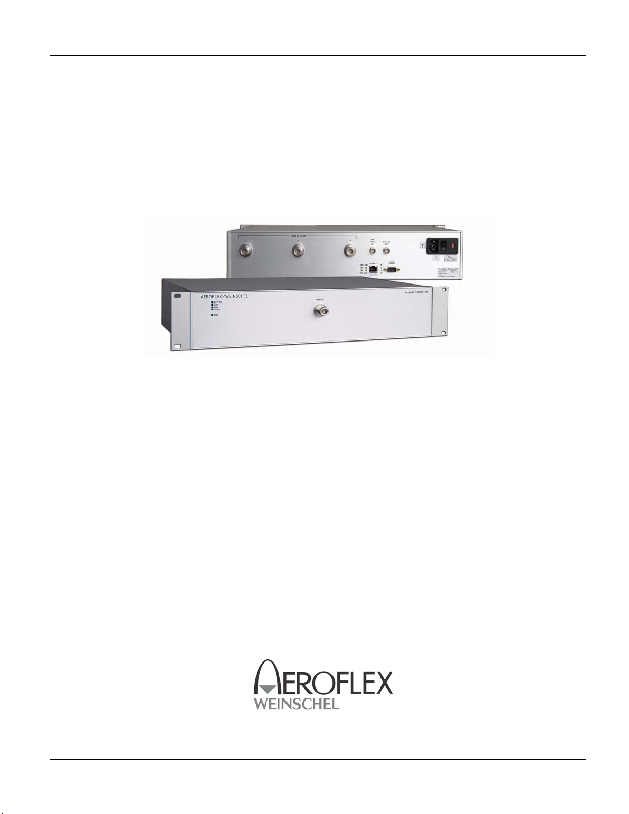
Model 8314-X
WLAN Simulator Subsystem
(P/N 193-8132-X)
This documentation may not be reproduced in any form, for any
purpose unless authorized in writing by Aeroflex / Weinschel, Inc.
© Aeroflex / Weinschel, Inc.
Frederick, Maryland
2008
Manual Rev. 4-2-08
Aeroflex / Weinschel 1
Firmware V2.0
Page 2
SAFETY SUMMARY
SAFETY SUMMARY
DEFINITIONS.
The following definitions apply to WARNINGS,
CAUTIONS, and NOTES found throughout this manual.
WARNING
An operating or maintenance procedure, practice,
statement, condition, etc., which, if not strictly
observed, could result in injury and/or death of
personnel. Do not proceed beyond a WARNING
symbol until all the indicated conditions have been
fully understood and/or met.
CAUTION
An operating or maintenance procedure, practice,
statement, condition, etc., which, if not strictly
observed, could result in damage or destruction of the
equipment or long-term health hazards to personnel.
Do not proceed beyond a CAUTION symbol until all
the indicated conditions have been fully understood
and/or met.
NOTE
An essential operating or maintenance procedure,
condition, or statement that must be highlighted.
•
To minimize shock hazard, the instrument chassis
must be connected to an electrical ground. Using
the supplied three-conductor power cable ensures
that the instrument can be firmly connected to the
ac power source and electrical ground at a
grounded power outlet. If using a 3-2 wire
adapter be sure to connect the ground lead to earth
ground.
•
Use the buddy system any time work involving
active high voltage components is required. Turn
OFF the power before making/breaking any
electrical connection. Regard any exposed
connector, terminal board, or circuit board as a
possible shock hazard. DO NOT replace any
component or module with power applied.
•
If test conditions to live equipment are required,
ground the test equipment before probing the
voltage or signal to be tested.
•
Personnel working with or near high voltage
should be familiar with modern methods of
resuscitation.
•
DO NOT wear jewelry (rings, bracelets, metal
watches, and/or neck chains) while working on
exposed equipment. Be very cautious about
using hand tools near exposed backplanes, bus
bars, and/or power supply terminals. Use
properly insulated tools. When making test
connections to the power supply terminals and
bus bars, use only insulated probe tips.
•
Verify that the instrument is set to match the
available line voltage and the correct fuse is
installed.
GENERAL PRECAUTIONS.
The following are general precautions that are not related
to any specific procedure and, therefore, do not appear
elsewhere in this publication. These are precautions that
personnel must understand and apply during various phases of
instrument operation or service.
WARNING
•
Potentially lethal voltages are present in this
instrument. Serious shock hazards from voltages
above 70 volts may exist in any connector,
chassis, or circuit board. Observe the following
precautions:
•
DO NOT install substitute parts or perform any
unauthorized modification to this instrument.
Contact Weinschel Corporation to acquire any
information on replacement parts or returning
the instrument for repair. Unauthorized
modification can cause injury to personnel and/or
destruction of the instrument.
•
Operating personnel must not remove instrument
covers. Component replacement or adjustments
MUST BE performed by qualified service
personnel.
•
DO NOT operate the instrument near or in the
presence of flammable gases or fumes.
DETAILED PRECAUTIONS.
The following WARNINGS, CAUTIONS and NOTES
appear throughout the text of this manual and are repeated here
for emphasis.
i
Page 3

SAFETY SUMMARY
•
All procedures and/or steps identified as
must be followed exactly as written and
according to industry accepted ESDS device
handling procedures. Failure to comply WILL
RESULT in ESDS damage.
•
DO NOT use a nylon bristle brush in the solvent
as the bristles may dissolve and cause damage to
the circuit card or component.
•
DO NOT use ultrasonic cleaning on parts or
assemblies containing electrical or electronic
components.
•
DO NOT bend pins of electrical connectors
when using fiber-bristle brush.
•
Compressed air used for cleaning and/or drying
can create airborne particles that may enter the
eye. Goggles/faceshields should be worn. DO
NOT direct air stream towards self or other
personnel. Pressure should be restricted to a
maximum of 15 psi to avoid personal injury.
•
Under no circumstances should a wire brush, steel
wool, or abrasive compound be used on any
surface. Using these items will cause extensive
damage to the instruments surface.
NOTE
CAUTION
DO NOT return any instrument or component to
Weinschel Corporation without receiving prior
factory authorization.
SAFETY SYMBOLS.
The following symbols are used to identify safety hazards
found throughout this publication and/or located on the
instrument.
CAUTION
HIGH VOLTAGE
WARNING
HIGH
VOLTAGE
ii
Page 4

Model 8314-X IM-477
TABLE OF CONTENTS
1. GENERAL INFORMATION ................................................................................................................................................. 4-7
1-1. PURPOSE ........................................................................................................................................................................................... 4
1-2. SCOPE ............................................................................................................................................................................................... 4
1-3. EQUIPMENT DESCRIPTION .......................................................................................................................................................... 4
1-4. UNPACKING AND INSPECTION ................................................................................................................................................... 4
1-5. RESHIPMENT INSTRUCTIONS ..................................................................................................................................................... 5
1-6. STORAGE INSTRUCTIONS ............................................................................................................................................................ 5
1-7. RELATED MANUALS ..................................................................................................................................................................... 6
1-8. ELECTROSTATIC DISCHARGE SENSITIVE ................................................................................................................................ 6
1-9. SAFETY CONSIDERATIONS .......................................................................................................................................................... 6
1-10. POWER REQUIREMENTS ............................................................................................................................................................ 6
2. FRONT & REAR PANEL CONNECTORS & INDICATORS .......................................................................................... 7-11
2-1. POWER ENTRY MODULE ASSEMBLY ..................................................................................................................................... 7-8
2-2. MOBILE & BASE STATION PORT CONNECTORS ..................................................................................................................... 8
2-3. FRONT PANEL LEDS ...................................................................................................................................................................... 8
2-4. EXTERNAL CONTROLS (REAR-PANEL BNC) ........................................................................................................................... 8
2-5. ETHERNET CONTROLLER LEDS & HARDWARE SETTINGS ............................................................................................ 8-11
2-5-1. STATUS LEDS ................................................................................................................................................................... 8
2-5.2. HARDWARE CONFIGURATION SWITCH SETTINGS ............................................................................................ 9-10
2-5.3. CONNECTOR PINOUTS ................................................................................................................................................. 11
3. COMMUNICATIONS ........................................................................................................................................................... 12
4. SIMULATION PARAMETERS & OVERVIEW .............................................................................................................. 13-14
5. PROGRAMMING .............................................................................................................................................................. 15-23
5.1. SIMULATION PARAMETERS ............................................................................................................................................. 15-17
5-2. SIMULATION CONTROL ..................................................................................................................................................... 18-19
5-3. SIMULATION DATA/DIRECT IO ........................................................................................................................................ 20-24
5-4. NETWORK CONTROL .......................................................................................................................................................... 24-25
5-5. HARDWARE CONTROL ............................................................................................................................................................ 25
5-6. DATA STORAGE ........................................................................................................................................................................ 26
6. MAINTENCE ..................................................................................................................................................................... 28-30
6-1. INSPECTION ................................................................................................................................................................................... 28
6.2. PREVENTIVE MAINTENANCE .................................................................................................................................................... 28
6.3. SPECIAL CLEANING INSTRUCTIONS ....................................................................................................................................... 28
6-3.1. MICROWAVE COAXIAL CABLE ASSEMBLIES ............................................................................................................ 28
6-3.2. CIRCUIT CARDS AND MODULES ................................................................................................................................... 28
6-3.3. MACHINED SURFACES AND HARDWARE ................................................................................................................... 29
6-3.4. CHASIS CLEANING ............................................................................................................................................................ 29
6-3.5. CONNECTOR CLEANING .................................................................................................................................................. 29
6.4. LINE VOLTAGE FUSE REPLACEMENT ..................................................................................................................................... 30
Aeroflex / Weinschel 2
Page 5

Model 8314-X IM-477
7. REPLACABLE PARTS LIST ................................................................................................................................................. 31
7-1. UNDERSTANDING REFERENCE DESIGNATORS .................................................................................................................... 31
7-2. ORDERING INFORMATION ......................................................................................................................................................... 31
7-3. DRAWING NUMBER ..................................................................................................................................................................... 31
7-4. REPLACABLE PARTS LIST .......................................................................................................................................................... 31
7-4.1. REFERENCE DESIGNATOR .......................................................................................................................................... 31
7-4.2. DESCRIPTION ................................................................................................................................................................. 31
7-4.3. PART NUMBER ............................................................................................................................................................... 31
7-4.4. VENDOR PART NUMBER ............................................................................................................................................. 31
7-5.5. CAGE CODE .................................................................................................................................................................... 31
7-4.6. ASSEMBLY AND COMPPONET LOCATION .............................................................................................................. 31
8314-1 WLAN SIMULATOR SUBSYSTEM REPLACEABLE PARTS LIST (P/N 93-8132-1) ...................................................... 32-33
8314-2 WLAN SIMULATOR SUBSYSTEM REPLACEABLE PARTS LIST (P/N 93-8132-2) ...................................................... 34-35
8. CONTACTING AEROFLEX / WEINSCHEL. ..................................................................................................................... 36
9. AEROFLEX / WEINSCHEL WARRANTY ........................................................................................................................ 36
10. ASSEMBLY/WIRING DIAGRAMS
MODEL 8314-1 ASSEMBLY DRAWING ............................................................................................................................... 193-8132-1
MODEL 8314-2 ASSEMBLY DRAWING ............................................................................................................................... 193-8132-2
MODEL 8314-1 WIRING DIAGRAM ........................................................................................................................................ 193-8133
MODEL 8314-2 WIRING DIAGRAM ........................................................................................................................................ 193-8134
MODEL 8314-1 INTERFACE CONTROL DRAWING (SPECFICATIONS) ............................................................................ 089-4037
MODEL 8314-2 INTERFACE CONTROL DRAWING (SPECIFICATIONS) ......................................................................... 089-4038
Aeroflex / Weinschel 3
Page 6
Model 8314-X IM-477
1. GENERAL INFORMATION:
1-1 PURPOSE: This manual contains setup and operation information for the Aeroflex / Weinschel’s 8314 WLAN
Simulator Subsystem (P/N 193-8132-X). The manual also provides component location, reference designators, part
numbers, and nomenclature to identify all the assemblies and sub-assemblies of the WLAN Simulator Subsystem.
1-2 SCOPE: This manual is to be used in conjunction with the operation and maintenance of a 8314 WLAN Simulator
Subsystem. The manual also provides a description of each assembly; assembly parts list; block diagrams: and
general maintenance procedures to maintain the instrument.
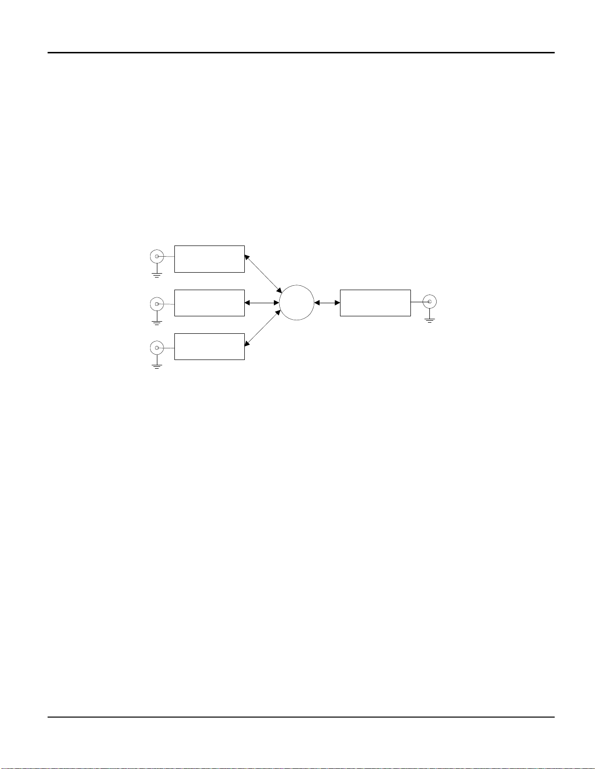
1-3 EQUIPMENT DESCRIPTION: The WLAN Simulator Subsystem (8314) is available in two frequency ranges and
is used to simulate the connectivity between a mobile running along a line of 3 base stations. Each of the three base
stations have an individually controlled attenuator, which are then combined, and passed thru a fourth attenuator used
to set the offset level. The attenuators are digitally controlled pin-diode absorptive attenuators, with a range of 0-63.75
dB in 0.25 dB steps. Refer to the RF Block Diagram below:
BS1
BS2
BS3
ATTN 1
(0-63dB )
ATTN 2
(0-63dB )
ATTN 3
(0-63dB )
3:1
ATTN 4
(0-63dB)
MOBILE
1-4. UNPACKING AND INSPECTION: Upon unpacking the equipment, retain the shipping container and packing
material for future shipment for recalibration. Perform the following initial inspection:
a. Carefully look at the outside of the shipping container for discoloration, stains, charring, or other signs of
exposure to excessive heat, moisture, or liquid chemicals. Check for any physical damage to the shipping
container such as dents, snags, rips, crushed sections or areas, or similar signs of excessive shoc k or
careless handling.
b. With the equipment and any accessory package removed from the shipping container, check each item
against the packing list or Items Supplied List. If any items are missing, contact the Aeroflex / Weinschel
Corporation Customer Service Department.
c. Carefully inspect the equipment looking for dents, deep scratches, damaged or loose connector, or any other
d. signs of physical abuse or careless handling. If damage is found, forward an immediate request to the
delivering carrier to perform an inspection and prepare a concealed-damag e report. DO NOT destroy any
packing material until it has been examined by an agent of the carrier. Concurrently, report the nature and
extent of damage to Weinschel Corporation, giving equipment model and serial numbers, so that necessary
action can be taken. Under U.S. shipping regulations, damage claims must be collected by the consignee;
DO NOT return the equipment to Aeroflex / Weinschel, Inc. until a claim for damages has been established.
Aeroflex / Weinschel 4
Page 7

Model 8314-X IM-477
1-5. RESHIPMENT: Use the best packaging materials available to protect the unit during storage or reshipment.
When possible, use the original packing container and cushioning material. If the original packing materials are not
available, use the following procedure:
a. Wrap the storage cases in sturdy paper or plastic;
b. Place the wrapped storage cases in a strong shipping container and place a layer of shock-absorbing material
(3/4 inch minimum thickness) around all sides of the unit to provide a firm cushion and to prevent movement
inside the container.
c. If shipping the unit for service, attach a tag to indicate:
1. model and serial numbers
2. service required
3. description of malfunction
4. return address
5. authorization to conduct repairs
6. return authorization number
d. Thoroughly seal the shipping container and mark it FRAGILE. Ship to:
Aeroflex / Weinschel, Inc.
Attn: Customer Service Department
5305 Spectrum Drive
Frederick, MD 21703-7362
or to an authorized sales representative.
1-6. STORAGE: Storage of the Model 8314 WLAN Simulator Subsystem is possible for extended periods without
incurring damage to internal circuitry if the 8314 Series is packaged according to the instructions above. The safe
limits for storage environment are as follows:
Temperature: 67° to +167 °F (-55° to +75 °C)
Humidity: less than 95% without condensation
Altitude: Up to 40,000 feet
1-7. RELATED MANUALS: The following manuals contain information that may be used in conjunction with this
manual to operate, service, or calibrate this instrument.
Manua
l Title
H4-1 and H4-2 Federal Supply Code for Manufacturers Cataloging Handbook
Aeroflex / Weinschel 5
Page 8

Model 8314-X IM-477
1-8. ELECTROSTATIC DISCHARGE SENSITIVE: The equipment documented in this manual contains certain
Electrostatic Discharge Sensitive (ESDS) components or parts. Therefore, certain procedures/steps are identified by
the use of the symbol . . This symbol is used in two ways:
CAUTION
All procedures and/or steps identified as must be followed exactly as written and according to
accepted ESDS device handling procedures. Failure to comply WILL RESULT in ESDS damage.
a. When the ESDS symbol is placed between a paragraph number and title , all of that
paragraph, including all subparagraphs, is considered ESDS device ha ndling procedure.
b. When the ESDS symbol is placed between a procedure/step number and the text , all of
that procedure is considered an ESDS device handling procedure.
1-9. SAFETY CONSIDERATIONS: The WLAN Simulator Subsystem and all related documentation must be reviewed
for familiarization with safety markings and procedures before any operation and/or service. Refer to the SAFETY
SUMMARY located at the beginning of this manual for a summary of safety information and procedures. Following
these simple safety precautions will ensure safe operation and service of the WLAN Simulator Subsystem.
1-10. POWER REQUIREMENTS: Aeroflex / Weinschel supplies a detachable power cable (P/N 068-21) to connect
an 100 to 240 Vac power source with a frequency between 50 to 60 H
Z to the WLAN Simulator Subsystem. To
minimize shock hazard, the instrument chassis must be connected to an electrical ground. Using the supplied threeconductor power cable ensures that the instrument can be firmly connected to the ac power source and electrical
ground (safety ground) at a grounded power outlet. Refer to paragraph 4-2 (Initial Setup) before applying any power
to the instrument.
Aeroflex / Weinschel 6
Page 9
Model 8314-X IM-477
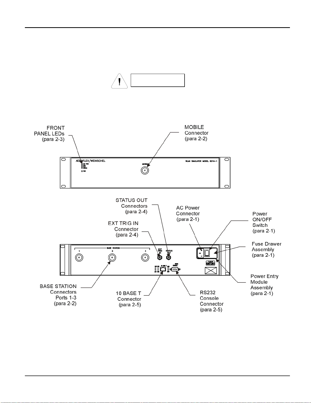
2. FRONT & REAR PANEL CONTROLS & INDICATORS:
The following paragraphs provide a description of the connections that can be made to the 8314 WLAN Simulator
Subsystem. Figure 1 shows the location of these connectors.
WARNING
Sufficient power levels are present at the Power Input Assembly to cause personal injury.
Ensure that the instrument power cord is DISCONNECTED before attempting to change
fuses.
Figure 1. Front & Rear Panel Connectors & Indicators
2-1 POWER ENTRY MODULE ASSEMBLY: The Power Entry Module Assembly located on the rear panel contains a
three-prong ac power input connector and a fuse drawer assembly (Figure 1). The Fuse Drawer Assembly contains
the line voltage fuse (Aeroflex / Weinschel P/N 052-1-1.5). The Model 8314 uses a T 1.5A, 250 Vac fuse which is 5 x
20 mm in size. Refer to paragraph 8-XXX for replacement of the fuse.
Aeroflex / Weinschel 7
Page 10

Model 8314-X IM-477
The AC Power Connector, located on the left side of XF1 (Figure 1), is a plug-type, prong insert connector with three
conductors for connection of the power cord (P/N 068-21) to the Power Supply Assembly located within the WLAN
Simulator Subsystem. This connector also grounds the chassis of the WLAN Simulator Subsystem when the the ac
power cord is connected to a grounded wall outlet. If necessary, use a three prong to two prong adapter and connect
the adapter’s ground lead to the outlet plate retaining screw.
The Power ON/OFF Switch is located on the rear panel and in part of the Power Entry Module Assembly. Placing the
POWER ON/OFF switch in the ON position applies power to the instrument.
CAUTION
When applying an RF signal to the RF INPUT connector, DO NOT exceed the maximum allowable
power level specifications of the Model 8314.
2-2. MOBILE & BASE STATION PORT CONNECTORS: There are three BASE STATION Ports location on
the rear panel and a Mobile Port on the front panel. These Type N female connectors provide a input and
output ports where RF signals can be applied to the devices internally mounted in the Model 8314.
2-3. FRONT PANEL LEDS: There are four leds plus a PWR indicator which are shown on the front panel:
FP LED FUNCTION
EXT TRIG When on, the trig mode is set to external. When off, trig mode is internal.
ARM When on, the system is awaiting a trigger event. Goes off when trig received.
RUN System has been triggered and is running. Goes out when sweep ends.
ERROR One or more of the setup parameters is invalid, and unable to run.
PWR Indicates that external power is applied to the unit.
2-4. EXTERNAL CONTROL CONECTORS: These BNC female connectors are located on the rear panel. The table
below outlines each connector’s parameters:
CONTROL CONNECTOR PARAMETERS
EXT TRIG INPUT TTL/CMOS compatible schmitt-trigger
Max input voltage range: -0.5V to +5.5V
High-level input voltage VIH: +2.1V minimum
Low-level input voltage VIL: +0.5V maximum
Internal 10 KΩ resistive pullup to +5V
ESD and current limit protected
Programmable polarity
STATUS OUTPUT
(simulation RUN state)
Aeroflex / Weinschel 8
High-level output voltage VOH +4.8V @ IOH=-50µA (RUNNING)
+3.2V @ IOH=-5mA
Low-level output voltage VOL +0.2V @ IOL=50µA (STOPPED)
+1.4V @ IOL=5mA
ESD and current limit protected
Page 11
Model 8314-X IM-477
2-5. ETHERNET CONTROLLER LED’s & HARDWARE SETTINGS: The following paragraphs provide a descri ption
for each of the rear panel Ethernet LEDs, hardware settings for the internal Ethernet controller card and signal – pin
locations for the 10BaseT and RS232 connectors. Figure 1 shows the location of these connectors.
2-5.1 STATUS LEDs:
LED FUNCTION
SYS Indicates that the Ethernet controller is enabled for operation in the system.
This LED flashes during boot and remains on during normal operation of the
switch.
ERR Indicates that a serious error has occurred during system boot.
ACT Indicates that activity is occurring over the 10BaseT Ethernet RJ-45 interface.
This LED flashes as transmit/receive activity occurs.
LINK Indicates that the Ethernet port has established a valid link with the network.
TX This LED flashes as the Ethernet Controller transmits data via the RS232
Console port.
RX This LED flashes as the Ethernet Controller receives data via the RS232
Console port
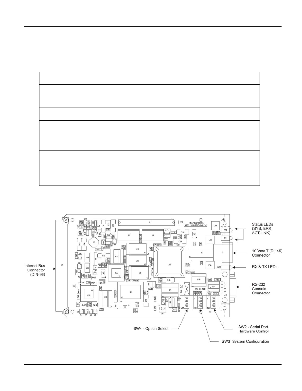
2-5.2. Hardware Configuration Switch Settings: Figure 2 is provided for component locatio n for the switches,
LEDs, connectors on the Ethernet controller card.
Figure 2. Ethernet Controller Card Switch/LED/Connector locations
Aeroflex / Weinschel 9
Page 12
Model 8314-X IM-477
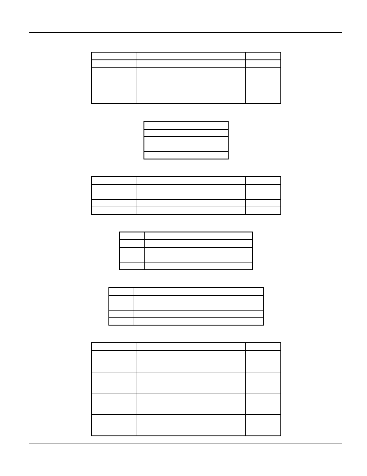
SW4 – Option Select
Name Description Default
1 --- unused off
2 --- unused off
3 BR1 Baud Rate Select
off
(see below)
BR0 Baud Rate Select off
Baud Rate Select
BR0 BR1 Rate
0 0 9600
1 0 19200
0 1 38400
1 1 57600
SW3 – System Configuration
Name Description Default
1 MS1 Memory Select off
2 MS2 Memory Select off
3 LS2 Load Sequence Overrid e (see below) off
4 LS1 Load Sequence Overrid e off
Memory Select
MS1 MS2 Description
0 0 Normal
1 0 External ROM card
0 1 Emulation mode (reserved)
1 1 Emulation mode (reserved)
Load Sequence Override
LS1 LS2 Description
0 0 Normal sequence
1 0 run RomMon w/WDOG disabled
0 1 run SysLoader
1 1 Normal sequence w/WDOG disabled
SW2 – Serial Port Hardware Control
Name Description Default
1 CTST RS422 Mode CTS Termination
off
Off – no termination
On – 120 ohm termination
2 RXDT RS422 Mode RXD Termination
off
Off – no termination
On – 120 ohm termination
3 RTSS RS422 Mode RTS line
off
Off – RTS+ not connected
On – RTS+ connected
4 MODE Serial Port Mode
off
Off – RS232
On – RS422
Aeroflex / Weinschel 10
Page 13
Model 8314-X IM-477
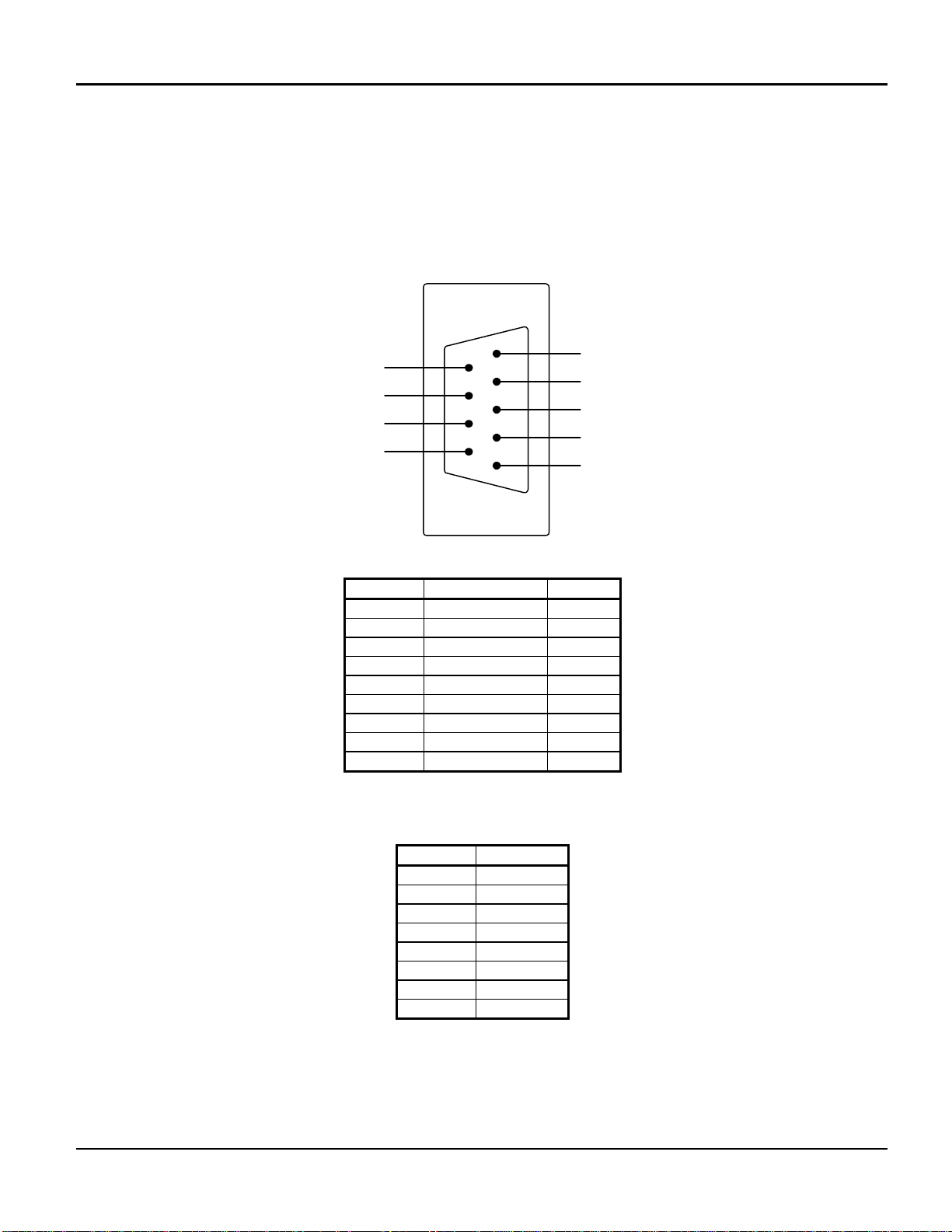
2-5.3 Connector Pinouts: The Ethernet controller card contains a 10BaseT (RJ-45) and a RS232 (DB9M) Console
connector that are mounted to the rear panel. There is also a table included for Internal Bus Connector, J8 located on
the Ethernet Controller card (DIN-96). Pin-outs for these connectors are as follows:
Serial Port Connector (DB9M)
RS232
9-pin DB9
Pinout
1
DSR
RTS
CTS
RI
6
7
8
9
DCD
2
RxD
3
TxD
4
DTR
5
GND
PIN NO RS232 RS422
1 DCD (unused) RXD+
2 RXD RXD3 TXD TXD4 DTR TXD+
5 GND GND
6 DSR (unused) CTS+
7 RTS RTS8 CTS CTS9 RI (unused) RTS+
10Base-T Ethernet Port (RJ-45)
PIN NO 10Base-T
1 TD+
2 TD3 RD+
4 Unused**
5 Unused**
6 RD7 Unused**
8 Unused**
** Unused pins on the RJ-45 have 75Ω/0.01µF to chassis to reduce noise.
Aeroflex / Weinschel 11
Page 14

Model 8314-X IM-477
3. COMMUNICATIONS:
The system provides both RS-232 serial port and 10BaseT Ethernet operation.
The RS-232 port can operate at 9600, 19200, 38400, or 57600 baud rates, selectable via internal DIP switch.
Default format is 9600N81. The serial port uses a standard DB9 DTE connector pinout. Connection to a standard
PC’s serial port requires the use of a “null-modem” type cable to swap the transmit and receive data pair (pins 2 and
3). A command-line interface (CLI) will be provided for interactive use w/ a terminal emulator. The CLI can be disabled
to facilitate use of the serial port as a programming interface. The CLI provides user prompts and supports simple line
editing (via the BS key) , last command recall (Ctrl-P), and a simple help facility. Help can be accessed from the main
command prompt using either the HELP or simply ‘?’. Additional help for many commands is available by specifying
the main command followed by a ‘?’. For example, “SET ?” provides a list of the SET commands, and “SET FREQ ?”
provides detailed info on the set frequency command.
Many commands and keywords allow abbreviated forms. Command abbreviations can be displayed using the
‘CMD ?’ help command. Also, there are some system level configuration/diagnostic commands, such as PING, that
can be listed using ‘SYS ?’ help command. Many of these require system-level password access.
10BaseT Ethernet will provide TELNET access (port 23) to the CLI for operation over a network. In addition,
TFTP client will also be supported for performing code updates to the flash memory. Network parameters (IP address,
subnet mask, TFTP host address, etc) can be set and stored/recalled from non-volatile memory. TFTP transfer is also
used to support the download/upload of the raw data tables, due to the potential volume of information to be
transferred. By default, the unit is configured for an IP address of 10.0.0.1, with a subnet mask of 255.255.255.0.
A NOTE ON PASSWORDS
Passwords are/can be used to prevent inadvertent configuration/switch changes. Password
protection is, generally, weak, in that a user can see the current password using the ‘SHOW CONFIG’
command. In addition, there is a fixed password (the word SYSTEM) that can be used that will grant
system-level access to many commands normally reserved for system testing/configuration.
Aeroflex / Weinschel 12
Page 15

Model 8314-X IM-477
λ
4. SIMULATION PARAMETERS AND OVERVIEW:
gain
xpos
BS1
ypos
gain
BS2
ypos
xpos
xpos
BS3
ypos
gain
2
⎞
⎟
⎟
⎠
22
GtGr
MOBILE
velocity
freq
gain
= wavelength
distance
stoppos
(origin)
startpos
The above diagram shows the user-entered parameters. When a simulation is initiated, the parameters are validated,
and the system builds its tables of attenuation setting vs time using the following relationship (Friis Transmission
Equation)
⎛
λ
LinkLoss
where
The system allocates a maximum of 10,000 data points for each attenuator for use over the entire simulation
time, for a total of 30,000 data points. The data tables are pre-built prior to the start of the simulation run, and typically
takes 3-4 seconds to complete.
When computing the data tables, the system notes the maximum signal level computed over the course of the
simulation, which will occur when the mobile position is at Xpos1, Xpos2, or Xpos3, depending on the basestation
gain and Ypos settings. This level, along with the nominal insertion loss of the unit, is used to set the Offset Attenuator
(ATTN4), whose value will not be changed over the course of the simulation. This offset will be subtracted from the
loss calculations of the three base station attenuators ATTN1-ATTN3, allowing the full range of these attenuators to
be used for the simulation in most cases. For basestation positions that are located far from the track, the Offset
Attenuator alone may not provide the reqd amount of attenuation, and this must be taken into account. For example,
for f=2000MHz, ypos=100m, the loss is 78dB. Since there’s only 63dB range in ATTN4, the remaining 78-63=15dB
will have to provided by the BS attenuator.
⎜
=
⎜
R
4
π
⎝
xposyposR += and
Simulation time is controlled via a 16-bit hardware timer/counter with 100nsec resolution , which provides a
max count time of 6.5536ms, with no pre/post-scaling.The actual required update rate is a function of the simulation
distance, mobile velocity, and the maximum number of allocated data points. The distance and velocity determine the
total simulation time:
Time =
mdistance
)/()(smvelocity
The system enforces a maximum update rate of 1msec. If Time is less than 10 secs (10,000pts * 1ms/pt),
then the update rate is fixed at 1msec, and the array size is reduced to cover the required time. If Time is greater than
10 secs, the entire 10,000 points are used, and the update rate is adjusted to cover the total simulation time.
Aeroflex / Weinschel 13
Page 16

Model 8314-X IM-477
The system also supports a “raw data mode”, in which the data tables are filled via external file download. This
allows the unit to support any arbitrary attenuation profile.
Operational Notes:
- set trigger mode
triggering can be set for INTernal or EXTernal. Ext trig is indicated on front-panel led.
- set trig polarity
external trig polarity can be set for active high (1) or active low (0) logic levels. Triggering is levelsensitive. Note that the EXT TRIG input is pulled high via a resistive pullup.
- set sweep mode
the simulation sweep can be set for SINgle or CONtinuous operation. In SINGLE mode, the
simulation will be run one time when a trigger event occurs, and will then stop. In CONT mode, when
the end of a simulation is reached, the simulation will be automatically restarted from the beginning,
depending on the current trigger mode. If the system is set for external triggering, then the triggering
subsystem is re-armed, and will wait for a new trigger event before continuing.
- set/show parameters
All parameters will have commands to set and query their current setting, as well as to be able to
restore the default settings. Summary commands will also be available to view multiple related
settings.
- run/stop simulation control
The RUN command initiates a simulation sweep. It performs the following:
1). All parameters are reviewed for validity. Note that while all the values are range-checked when
they are entered, some parameter values are coupled, and cannot be validated until all parameters
are entered. An example of this is the mobile position vs mobile distance. If the parameter values
result in an invalid simulation, the run is aborted and the front-panel ERROR led is illuminated.
2). Assuming the parameters are valid, the attenuation vs time profile data is computed, and stored in
internal tables. The triggering subsystem goes from the IDLE to the ARMED state, in which it waits for
a trigger event to occur. The front-panel ARM led is illuminated.
3). If the trig mode is set to INTernal, the triggering subsystem automatically transitions from the
ARMED to the RUNNING state. For external triggering, the ARMED to RUNNING state transition
occurs when the system detects the external trigger event. The front-panel RUN led is illuminated,
and the external STATUS output is asserted high.
4). Simulation runs, with the basestation attenuators (1-3) being updated periodically over the course
of the simulation.
5). When the end of the simulation is reached, if the sweep mode is SINGLE, then the simulation
ends, the RUN led goes off, and the external STATUS output is low. Otherwise the triggering is
rearmed, and the simulation goes to step 3. In the CONTinuous sweep mode, the simulation will be
re-run until the STOP command is given.
Aeroflex / Weinschel 14
Page 17

Model 8314-X IM-477
5. PROGRAMMING:
5-1. Simulation Parameters: In general, parameter ranges have been set to cover most real-world (and some
not so real) conditions. The simulation can be run over a 20km total distance (12.4 miles), at speeds up to 320km/hr
(approx 200mph). The system will not attempt to limit the selection of parameters, with the exception that the mobile
and basestation positions must be within the MOBILE DISTANCE (total simulation distance) setting. This allows the
maximum flexibility, but note that it also allows the user to set up scenarios that are not very realistic, or that could
result in extremely long simulation runs.
SET BASESTATION POSITION
Syntax
SET BASESTATION POSITION <select> <xpos> <ypos>
SET? BASESTATION POSITION <select>
Parameters
<select> basestation select (1-3)
<xpos> x-axis distance from the origin, in meters (0-20000)
<ypos> y-axis distance from the track, in meters (1-100)
Description
Sets the position of the selected basestation. The position along the X axis should be <= the MOBILE
DISTANCE setting. There are no restrictions on the order or positioning between the three ba se stations.
Example
SET BASESTATION POSITION 1 2500 50
sets the position of basestation 1 to 2500 meters from the start, at an offset
of 50 meters
SET BASESTATION GAIN
Syntax
SET BASESTATION GAIN <select> <gain>
SET? BASESTATION GAIN <select>
Parameters
<select> basestation select (1-3)
<gain> gain factor, in dB (-10.0 to +10.0)
Description
Sets the antenna gain factor, in dB, for the specified basestation.
Example
SET BASESTATION GAIN 1 -1.5
sets the gain of basestation 1 to -1.5dB, providing loss
Aeroflex / Weinschel 15
Page 18

Model 8314-X IM-477
SET MOBILE DISTANCE
Syntax
SET MOBILE DISTANCE <dist>
SET? MOBILE DISTANCE
Parameters
<dist> simulation distance, in meters (1-20000)
Description
Sets the total distance travelled for the simulation. Setting this parameter will automatically reset the
MOBILE POSITION to cover the distance specified
Example
SET MOBILE DISTANCE 10000
sets the distance to 10000 meters
SET MOBILE VELOCITY
Syntax
SET MOBILE VELOCITY <vel>
SET? MOBILE VELOCITY
Parameters
<vel> velocity, in km/hr (1-320)
Description
Sets the speed of the mobile, in kilometers/hr
SET MOBILE GAIN
Syntax
SET MOBILE GAIN <gain>
SET? MOBILE GAIN
Parameters
<gain> gain factor, in dB (-10.0 to +10.0)
Description
Sets the antenna gain factor, in dB, for the mobile.
Example
SET MOBILE GAIN -1.5
sets the gain of mobile to -1.5dB, providing loss
Aeroflex / Weinschel 16
Page 19

Model 8314-X IM-477
SET MOBILE POSITION
Syntax
SET MOBILE POSITION <startpos> <stoppos>
SET? MOBILE POSITION
Parameters
<startpos> x-axis starting distance from the origin, in meters (0-20000)
<stoppos> x-axis stopping distance, in meters
Description
Sets the mobile start and stop position, relative to the origin. Normally, these values would be set
to cover the MOBILE DISTANCE setting. This command allows the user to travel over a portion of
the total simulation distance. Note that changing this setting has no effect on the actual simulation
data or update rate, as the data is based on the entire distance.
SET FREQ
Syntax
SET FREQ <mhz>
SET? FREQ
Parameters
<mhz> frequency, in MHz (2000-6000)
Description
Sets the current operating frequency for use by the loss calculations.
SHOW PARAM
Syntax
SHOW PARAM
Description
Displays the current setting of all the user-entered simulation parameters.
SAVE PARAM
Syntax
SAVE PARAM
Description
Saves the current setting of all the user-entered simulation parameters into non-volatile memory .
These settings will be recalled during next system bootup.
Aeroflex / Weinschel 17
Page 20

Model 8314-X IM-477
5-2. Simulation Control
SET TRIGGER MODE
Syntax
SET TRIGGER MODE <mode>
SET? TRIGGER MODE
Parameters
<mode> trigger mode, INT or EXT
Description
Selects internal or external triggering for the simulation. With internal triggering, the simulation runs
automatically after a RUN command is received. When external triggering is selected, the simulation
will wait for an external trigger event before the simulation starts.
SET TRIGGER POLARITY
Syntax
SET TRIGGER POLARITY <pol>
SET? TRIGGER POLARITY
Parameters
<pol> active level, 0 or 1
Description
Sets the external trigger polarity level. Setting <pol>=0 sets an active-low external trigger, while a
<pol> of 1 sets an active-high trigger level. The external trigger input has a resistive pull-up, so that
if trigger input is left unconnected it will default to a high level.
SET SWEEP MODE
Syntax
SET SWEEP MODE <mode>
SET? SWEEP MODE
Parameters
<mode> sweep mode, CONT or SINgle
Description
Sets the simulation sweep mode. In SINGLE mode, once a simulation is triggered the simulation
will run once and then stop. If the sweep is set for CONTinuous operation, when the simulation
reaches the end it will return to the armed state and await another trigger event.
RUN
Syntax
RUN [CALC]
Description
Initiates/computes a simulation run. In its basic form, the RUN command computes the
attenuator data tables based on the entered parameters, and places the triggering subsystem in
the armed state, awaiting a trigger event. If the optional CALC switch is specified, the command
will only perform the calculations, and will not arm the trigger. This is useful if the user desires to
view the simulation results prior to actually running the simulation.
Aeroflex / Weinschel 18
Page 21

Model 8314-X IM-477
STOP
Syntax
STOP
Description
Stops a running simulation.
SHOW CALC
Syntax
SHOW CALC
Description
Displays various results of the simulation calculations, including total
time, max levels, update rate, etc
SHOW STATUS
Syntax
SHOW STATUS
Description
Displays the current state of a simulation.
Sets the simulation sweep mode. In SINGLE mode, once a simulation is triggered the simulation will run once
and then stop. If the sweep is set for CONTinuous operation, when the simulation reaches the end it will
return to the armed state and await another trigger event.
Aeroflex / Weinschel 19
Page 22

Model 8314-X IM-477
5-3. Simulation Data/Direct IO
These commands provide access to the raw simulation data and control, and can be used to override or view the
internal calculation data.
SET DATA CALC
Syntax
SET DATA CALC <mode>
Parameters
<mode> calc mode 0 or OFF, 1 or ON
Description
This command can be used to enable/disable the loss calculations. With calc off, the system allows
the data tables to be filled with arbitrary data using the SET DATA, SET DATA TIMER, and SET
DATA POINTS commands.
NOTE: this is not a new command, but it now allows use of the parameters ON and OFF instead of just 0/1
SET DATA POINTS
Syntax
SET DATA POINTS <numofpts>
Parameters
<numofpts> number of data points (1-10000)
Description
Sets the number of data points to use for a simulation run in table mode. Each point must be filled
using the SET DATA command
SET DATA
Syntax
SET DATA <pt> <attn1> <attn2> <attn3>
Parameters
<pt> data point number (0-10000)
<attn1> attenuator 1 setting, in dB
<attn2> attenuator 2 setting, in dB
<attn3> attenuator 3 setting, in dB
Description
Sets a data point for use in table mode (DATA CALC 0). Data point 0 is the initial setting at time
0. The range of the attn setting is dependant on the attenuator configuration, but is typically 0 to
63.75 in 0.25dB steps. Note: Control of the Offset Attn (Attn4) setting may be done using the
ATTN command
Aeroflex / Weinschel 20
Page 23

Model 8314-X IM-477
SET DATA TIMER
Syntax
SET DATA TIMER <secs>
Parameters
<secs> simulation update rate, in secs (0.001-60.000)
Description
Sets the attenuator update rate in table mode. The total simulation time is
determined from DATA TIMER * DATA POINTS
SHOW DATA
Syntax
SHOW DATA <startidx> <endidx> [FMT]
Parameters
<startidx> starting data array index (0-10000)
<endidx> ending data array index (0-10000)
[FMT] optional formatting flag
Description
Displays the simulation data array. The response shows the point number, and the data for each
of the three attenuators at that point. The default format for the attenuation data is the integer
programming word (0-255), which can be changed to display attenuation by using the optional FMT
specifier
ATTN
Syntax
ATTN <select> <setting>
ATTN? <select>
Parameters
<select> attenuator select (1-4)
<setting> attenuation value, in dB (0-63.75)
Description
Directly sets an attenuator setting. This command is useful for testing and diagnostics.
SET OFFSET ATTN
Syntax
SET OFFSET ATTN <setting>
SET? OFFSET ATTN
Parameters
<setting> attenuation value, in dB (0-63.75)
Description
Sets the Offset Attenuator value. The dB value specified in <setting> will be rounded to the resolution of the
attenuator. This command is useful for setting an offset while using Data Table mode, and is equivalent to the
'ATTN 4 xx' command.
Aeroflex / Weinschel 21
Page 24

Model 8314-X IM-477
FILL DATA
Syntax
FILL DATA <setting>
Parameters
<setting> attenuation value, in dB (0-63.75)
Description
Fills the data tables with the specified db value.
SHOW TIME
Description
Shows current system time in hrs:min:secs.msec and elapsed time since last invocation. Useful for timing
script execution.
SHOW ERROR COUNT
Description
Shows count of total errors since last invocation. Useful for script debugging.
SHOW FILE
Syntax
SHOW FILE [DATAFLASH:]
Description
This command can be used to display the status and contents of the dataflash: storage area
(including the name and size) if the optional 'DATAFLASH:' or 'DF: ' parameter is specified.
Otherwise, it displays the status of both the flash: and dataflash: file storage areas, including header
information, crc's, version, date, size, etc.
The first line of each section contains status information for each copy in the form 'Status (backup copy,
working copy)'. A status of 0 indicates the file is valid, while <0 indicates an error was detected in the copy.
The remaining
info is from the copy that is/will be in use. For example, flash: Status(-252, 0) indicates that there is a CRC
error
in the backup copy, while the working copy is ok.
EXECUTE SCRIPT
Syntax
EXECUTE SCRIPT [ECHO]
Description
This command executes the command script file stored in the dataflash: (df:) device. If the optional 'ECHO'
keyword is provided, then the command will display the script on the current console device as it is executed.
The command script file may contain any executable command supported by the CLI. Lines are limited to
128 chars in length, and should end with an ascii CR (0x0d), LF (0x0a), or any combination of the two.
Comment lines are optional, and if usedmust begin with either an ascii single-quote character (0x27), or an
ascii '/' char (0x2f).
Script files are stored into the dataflash: using the COPY TFTP command, and are limited to a maximum
total length of 512K bytes. The current contents of the dataflash: can be viewed using the SHOW FILE DF:
command.
Aeroflex / Weinschel 22
Page 25

Model 8314-X IM-477
COPY source destination
Syntax
COPY TFTP:<url-filename> {FLASH: | DATAFLASH:}
COPY {FLASH: | DATAFLASH:} TFTP:<url-filename>
Access-level : password
Description
Copies remote file identified by <url-filename> via TFTP to/from application flash: or dataflash: memory. The
first argument is the source, the second is the destination. It allows the user to download an image from the
network and save in flash, or upload an image from flash to the network server. By default, the transfer uses
the host IP address specified by SET TFTPHOST. However, if the <url-filename> contains an IP address, the
transfer will use this address instead.
For example, 'copy tftp://10.0.0.10/file.bin flash:' would attempt to download the file from the specified
address of 10.0.0.10, ignoring the current TFTPHOST setting, if any.
Each of the data storage devices only reserve space for a single file, so any downloads will overwrite the
current contents. As such, any filename parameters for the fl: and df: destinations are used strictly as
placeholders.
The command accepts the abbreviations of 'FL:' and 'DF:' for the flash: and dataflash: devices, respectively.
ENABLE
ENABLE PASSWORD
DISABLE
Syntax
ENABLE
ENABLE <plain-text>
ENABLE PASSWORD <plain-text>
NO ENABLE PASSWORD
DISABLE
RECOVER PASSWORD
SHOW PASSWORD\0
see also: SET ACCESS SYSTEM
Access-level : all
Description
The mrs software provides two levels of access to commands: user and privileged. The unprivileged user
mode is called 'user exec' mode. The privileged mode is called 'privileged exec' mode and normally req uires
entry via a password. The commands available in 'user exec' mode are a subset of the commands available
in 'privileged
exec' mode.
The ENABLE and DISABLE commands are used to enter and leave privileged exec mode, respectively. If a
password has been set, the user will be prompted to enter in the password. Once entered, the prompt
changes to 'mrs#' to show the current mode. You may bypass the 'password:' prompt by including the
password along
with the ENABLE keyword on the command line.
To set an access-level password, use the 'ENABLE PASSWORD <plain-text>' command, where <plain-text>
specifies the desired password, and may be up to 11 chars in length. The password is stored in nvram. The
command 'NO ENABLE PASSWORD' deletes the password and removes it from nvram storage, as long as
you are in privileged mode.
Aeroflex / Weinschel 23
Page 26

Model 8314-X IM-477
There is a password recovery feature that allows the user to view/erase the current password without being
in privileged mode. This can be accessed only via a local serial port connection to the console, and will not
work over a telnet connection.
To erase the password, you must first send an RS232 BREAK signal. You should see the console respond
with the message '**BREAK** detected. Password recovery enabled'. Once password recovery is enabled,
you can use the 'SHOW PASSWORD' command to display the current password, or you can send
'RECOVER PASSWORD', which will erase the current password setting. If successful, you will get the
message 'Password reset'. Password recovery mode is automatically terminated after receipt of any two CLI
commands, after which you will get an 'Access denied' error, and have to repeat the steps.
5-4. Network Configuration
SHOW NETWORK CONFIG
Syntax
SHOW NETWORK CONFIG
Description
Displays the current setting of the configuration parameters, including MAC and IP addresses, tftp
host, password, etc.
SET IP ADDRESS
Syntax
SET IP ADDRESS <ip-addr> [<subnet-mask>]
Access-level : password
Description
Sets the IP address of the ethernet interface to <ip-addr> with a network mask <subnet-mask>, if
supplied. Both <ip-addr> and <subnet-mask> are in the form of A.B.C.D.
By default, the IP address is 10.0.0.1, with a subnet mask of 255.255.255.0
SET IP GATEWAY
Syntax
SET IP GATEWAY <ip-addr>
Access-level : password
Description
Sets the IP address of the default gateway used to access addresses outside the local subnet.
The <ip-addr> parameter is in the form of A.B.C.D.
Changes made to this parameter will not take effect until the system is rebooted (see RELOAD).
SET TELNET TIMEOUT
Syntax
SET TELNET TIMEOUT <secs>
Description
Sets the inactivity timeout for TELNET sessions, in secs. <secs> can be in the range of 30 to
1800 (30 mins). The default timeout is 600 secs (10 mins).
Aeroflex / Weinschel 24
Page 27

Model 8314-X IM-477
SET TFTPHOST
Syntax
SET TFTPHOST <ip-addr>
Description
Sets the IP address for a remote TFTP server, which is used by the COPY cmd.
PING
Syntax
PING <ip-addr>
Description
Sends ICMP ECHO packets to <ip-addr>, and reports the results. The packets are 32 bytes in length.
COPY source destination
Syntax
COPY TFTP:<url-filename> {FLASH: | BOOTFLASH:}
COPY {FLASH: | BOOTFLASH:} TFTP:<url-filename>
Description
Copies remote file identified by <url-filename> via TFTP to/from application flash: or sysloader
bootflash: memory. The first argument is the source, the second is the destination. It allows the
user to download an image from the network and save in flash, or upload an image from flash to the
network server. By default, the transfer uses the host IP address specified by SET TFTPHOST.
However, if the <url-filename> contains an address, the transfer will use this address instead. For
example, 'copy tftp://10.0.0.10/file.bin flash:' would attempt to download the file from the specified
address of 10.0.0.10, ignoring the current TFTPHOST setting, if any.
RELOAD
Syntax
RELOAD
Description
Reboots the system, performing the boot-up sequence as if from power-up.
5-5. Hardware Configuration
CONFIG commands are typically used during system mfg and set up, and should not normally be
changed by the user, unless instructed to do so. These commands require system-l evel access.
CONFIG ATTN <maxdb> <stepdb>
Sets the attenuator max setting and stepsize, in dB
CONFIG FREQ <minf> <maxf>
Sets the min and max freq range, in MHz
CONFIG LOSS <minl> <maxl>
Sets the insertion loss min and max (at min/max freq), in dB
SAVE CONFIG
SHOW CONFIG
Aeroflex / Weinschel 25
Page 28

Model 8314-X IM-477
5-6. Data Storage
The MRS has a new logical storage device referred to as the dataflash: ( or DF: ). While the dataflash: cannot
be used to directly store the simulation data tables, the dataflash: can be loaded with a text script file that can be used
for a variety of purposes. The script file can contain any sequence of commands that are recognized from the CLI,
and can be executed on command much like a batch file. The dataflash: script file is loaded via downloading the file
from a network TFTP server connection. Once copied, the file is stored in non-volatile memory on the controller and is
automatically saved for future execution. The script file can then be executed via a CLI command. While the script file
can contain any sequence, it is particularly useful for setting up the simulation data tables.
While the data tables can be loaded via cli commands, it can take a long time to send the sequence via the serial port
or even a network telnet connection, especially for a large number of data points. Also, without the dataflash:, the data
points are lost upon power-down. The dataflash: fixes these issues.
To use the dataflash:, you must create an ASCII text file that has the desired sequence of commands. The
lines of the file should be limited to 128 characters in length, and terminated with an ASCII CR (0x0D) , LF (0x0A) or
both. The file can contain empty (blank) lines for readability, and can also contain comments lines. Comment lines are
those lines that begin with either a single slash character (0x2F) , a double slash, or a single quote (0x27) character.
Examples are shown below:
/ THIS IS A COMMENT
set data 1 12.45 13.45 13.45
// also a comment
set data 2 1.2 2.2 3.2
' YET ANOTHER COMMENT
There are no formal limits on the number of lines contained in a script file, but the file size must be limited to a
maximum of 512K bytes to fit into the dataflash: storage area ( a typical 10,000 point data script file is roughly 324K
in size). An example 10-point data file might look like:
// setup general simulation params
// turn off calculations (sets table mode)
set data calc off
// number of points
set data points 10
// update rate of 1ms per point
set data timer 0.001
// init the offset attn (#4)
set offset attn 10.5
// fill table with 0dB
fill data 0
// data points
set data 0 0.25 0.5 0.75
set data 1 1.25 2.25 3.25
set data 2 2.5 4.5 6.5
set data 3 3.75 6.75 9.75
set data 4 5 9 13
set data 5 6.25 11.25 16.25
set data 6 7.5 13.5 19.5
set data 7 8.75 15.75 22.75
set data 8 10 18 26
set data 9 11.25 20.25 29.25
set data 10 12.5 22.5 32.5
// comment end of file
Aeroflex / Weinschel 26
Page 29

Model 8314-X IM-477
Once the file has been created, the next step is to transfer it to the MRS. This is done via the network using
the TFTP file transfer protocol. Place the file on a PC running a TFTP server that the MRS can communicate with. If
you do not have a TFTP server, there are several freeware/open source packages available on the internet, such as
tftpd32 (available at http://tftpd32.jounin.net/
from the CLI. Use the COPY command to perform the download to the MRS’s dataflash: device. For example, if the
tftp server is at address 10.100.103.100, and the file is named “example.txt” you could use the command:
). The MRS contains a TFTP client that can be used to initiate the transfer
mrs> copy tftp://10.100.103.100/example.txt df:
This should initiate the transfer, download, and store the file into the dataflash: device. Note: as shown above,
the target name for the file in the dataflash: is optional. Since the dataflash: can only hold a single file, the name is
used for information purposes only. The name, if provided, will be displayed via the
Once succesfully transferred, the script file can be executed from the command line via the EXECUTE
SCRIPT command, which will parse and execute the series of commands from the file, after which a short summary is
displayed. If you would like to see the script as it executes, you can use EXECUTE SCRIPT ECHO, which is useful for
finding errors in the script. You can display the contents of the dataflash: to the console using the command SHOW
FILE DF: Once executed, the data table will contain the desired attenuation profile, and the simulation can be
controlled via the normal RUN, STOP, etc commands.
Using the dataflash: to store the script is most useful for large data sets. After all, since the script file consists
puely of executable commands, you could just send the contents of the script file via telnet for direct execution by the
MRS, and this works fine for small data sets. It can be, in fact, faster to do this than to use COPY TFTP: and
EXECUTE SCRIPT. Once the data set becomes larger, it’s more efficient to transfer the file to the dataflash:. Some
typical times vs file sizes are shown below
Data
points
100 2.2 sec 4 sec / 0.4 sec = 4.4 sec
500 9.1 sec 4.9 sec / 1.7 sec = 6.6 sec
1000 17.8 sec 5.9 sec / 3.3 sec = 9.2 sec
5000 88.2 sec 14.5 sec / 16.3 sec = 30.8 sec
10000 176.3 sec 26.4 sec / 32.5 sec = 58.9 sec
Also, once the file has been stored in the dataflash:, it can be used again the next time the unit is powered up
simply by using the EXECUTE SCRIPT command, saving the time required to re-download the file.
You can also retreive the contents of the dataflash: storage. The following command would create a file
named “example.txt” on the TFTP server, and copy the contents of the dataflash: to it.
Telnet
transfer
Tftp transfer/execute
mrs> copy df: tftp://10.100.103.100/example.txt
Aeroflex / Weinschel 27
Page 30

Model 8314-X IM-477
6. MAINTENANCE:
The following paragraphs provide general inspection and maintena nce guide lines for the Model 8314 WLAN
Simulator Subsystem.
6-1. INSPECTION: Perform a visual inspection in conjunction with the maintenance activities schedule when a
malfunction is suspected, or whenever an assembly is removed or replaced.
6-2. PREVENTIVE MAINTENANCE: While the 8314 requires very little preventive maintenance, it should not be
subjected to physical abuse, severe mechanical shock, high humidity, or operating temperatures outside the
specification range. The instrument should be kept free of excessive dirt and dust, since these can interfere with
connector functions and with normal heat dissipation. For cleaning instructions refer to paragraph 6-3 (special
cleaning instructions). The following paragraphs provide the preventive maintenance that is to be performed on the
Unit.
Care should be taken to prevent strain on the interconnecting cables, since damage here may not always be
apparent. Occasionally check the external cables and connectors for signs of cracked insulation and/or bent or worn
pins. Tests show that connectors must be clean for accuracy and stability. This requires an inspection and cleaning of
each connector immediately before use. For connector cleaning instructions, refer to paragraph 6-3. When cleaning
precautions are observed regularly, connectors can maintain their stability for over several thousand connection
cycles. Refer to Appendix A for more information about cables and connectors.
6-3. SPECIAL CLEANING INSTRUCTIONS: The cleaning procedures for 8314 are divided into five general groups:
microwave coaxial cable assemblies, circuit card and modules; machined surfaces and hardware, chassis cleaning,
and connector cleaning.
6-3.1. MICROWAVE COAXIAL CABLE ASSEMBLIES: Appendix A (located at the end of this manual) provides all
the necessary procedures for care, cleaning, and handling of microwave coaxial cable assemblies.
6-3.2 CIRCUIT CARDS AND MODULES: A protective coating is applied to circuit cards for protection from moisture,
arcing, short-circuiting, and abrasion. To remove light dirt from circuit cards and modules proceed as follows:
CAUTION
• DO NOT use a nylon bristle brush in the solvent as the bristles may dissolve and cause
damage to the circuit card or component.
• DO NOT use ultrasonic cleaning on parts or assemblies containi ng electrical or electronic
components.
• DO NOT bend pins of electrical connectors when using fiber-bristle bru sh.
a. Briskly brush isopropyl alcohol onto area to be cleaned with fiber-bristle brush.
b. Carefully remove residue with a clean lint-free cloth and repeat step "a" as a rinse.
WARNING
Compressed air used for cleaning and/or drying can create airborne particle s that may
enter the eye. Goggles/ faceshields should be worn. DO NOT direct air stream to wards
self or other personnel. Pressure should be restricted to a maximum 15 psi to avoid
personal injury.
c. When parts are thoroughly clean, dry parts using 5 psi of clean moisture free compressed air or
preferably dry nitrogen (pressurized spray will work well).
Aeroflex / Weinschel 28
Page 31

Model 8314-X IM-477
6-3.3 MACHINED SURFACES AND HARDWARE: To remove light dirt and dust from mechanical parts such as
castings, covers and other hardware proceed as follows:
WARNING
Compressed air used for cleaning and/or drying can create airborne particle s that may
enter the eye. Goggles/ faceshields should be worn. DO NOT direct air stream to wards
self or other personnel. Pressure should be restricted to a maximum 15 psi to avoid
personal injury.
CAUTION
• Under no circumstances use a wire brush, steel wool, or abrasive compound. Using
these items will cause extensive damage to the instrument's surface.
• DO NOT use a nylon bristle brush in solvent as the bristles may dissolve and cause
damage to the circuit card or component.
a. Use 5 psi of clean, moisture-free compressed air or preferably dry nitrogen to blow loose dirt and dust
from surface of item.
b. Briskly brush isopropyl alcohol onto area to be cleaned with a fiber-bristle brush.
c. Remove residue with lint-free cloth and repeat step "b" as a rinse.
d. When parts are thoroughly clean, dry parts using 5 psi of clean, moisture-free compressed air or
preferably dry nitrogen.
e. Clean smaller mechanical parts or hardware by dipping into a container of isopropyl alcohol. Remove dirt
by brushing with fiber-bristle brush after parts have been immersed for several hours.
f. Remove parts from isopropyl alcohol and rinse by immersing into a different container of isopropyl
alcohol.
g. When parts are thoroughly cleaned, dry parts using 5 psi of clean, moisture-free compressed air or
preferably dry nitrogen.
6-3.4 CHASSIS CLEANING: Clean chassis using a lint-free cloth moistened with water and mild detergent. For
harder to clean areas, such as inside corners of chassis, use a vacuum cleaner.
6-3.5 CONNECTOR CLEANING: Where small amounts of rust, corrosion, and/or oxide deposits are present on
connectors, clean externally with a soft-bristle brush, aluminum wool, or internally with an acid brush; then wa sh with
a non-corrosive solvent. MIL-C-83112 is recommended. Exercise care to ensure no metal filing or resid ue remains
inside the connector and the connector is thoroughly dry. Where rust, corrosion, and/or oxide depo sits are present in
large quantities, replace the connector.
Aeroflex / Weinschel 29
Page 32

Model 8314-X IM-477
6-4. LINE VOLTAGE FUSE REPLACEMENT: The following steps provide procedures to replace the line voltage
Fuse Assembly. This unit accepts a F1.5A, 250 Vac fuse for 115 Vac.
WARNING
Sufficient power levels are present at the Power Input Assembly to cause personal injury.
Ensure that the instrument power cord is DISCONNECTED before attempting to change
fuses.
CAUTION
DO NOT connect or apply power to this instrument until the Power Entry Module
Assembly has been adjusted to the operational line voltage.
a. Disconnect the power cord from the Power Entry Module Assembly.
b. Use a small screwdriver to carefully open the Fuse Drawer.
c. Slide out Fuse Drawer located in the center of the Power Entry Module Assembly.
d. Remove defective fuse and replace with the correct fuse (Refer to applicable parts list for
fuse part number).
e. Snap the Fuse Drawer shut and re-connect ac power cord.
Aeroflex / Weinschel 30
Page 33

Model 8314-X IM-477
7. REPLACEABLE PARTS LIST:
This section lists and describes the parts located in the Model 8314 WLAN Simulator Subsystem (P/N 1938132-X). The Replaceable Parts Lists (RPL) are intended for use in identifying, locating, and requisitioning
assemblies and components for the Model 8314.
7-1 UNDERSTANDING REFERENCE DESIGNATORS: All assemblies and electrical parts are identified by standard
reference designators (resistors R1, for example). Reference designators are used in parts lists and on parts
identification drawings. The title of a parts list or drawing contains the reference designator or the assembly or
subassembly to which it applies. The designators in the parts list, as a prefix, but omitted from the list to make it
easier to locate a specific part. To complete a reference designator in a parts list, precede the designator for the
specific part (DS1, for example) with the designator in the title (A6, for example) to form a complete reference
designator for the part (in this case, A6DS1).
7-2 ORDERING INFORMATION: When ordering parts from Ae roflex / Weinschel, please include the following
information:
• Aeroflex / Weinschel part number.
• Description of the component or part.
• Model and serial number of the instrument.
• Assembly number and assembly revision (if any) from the assembly
(this information is on the component side of the PCB).
7-3 DRAWING NUMBER: The Aeroflex / We insch el par t numb er cons is ts of a ba s ic numb er wi th a d ash numb er. T he
basic number should cross reference to a drawing number for most of the items. For those items that do not have a
drawing number, the manufacturers part number is provided.
7-4 REPLACEABLE PARTS LIST (RPL): This RPL contains a breakdown of the instrument into its major assemblies
and detailed parts. The following paragraphs describe the contents of each column of the RPL.
7-4.1 REFERENCE DESIGNATOR: This column contains refere nce designations arranged in alphanumerical
sequence. The letters A thru Z have precedence, followed by numerals 0 thru 9. In addition to the reference
designators that are listed, some mechanical parts are also listed. These items lack reference designators and are
included because they are considered subject to wear and/or breakage, or because they are custom (non-standard)
hardware or parts that might become lost or damaged. This column contains the word N/A for those items or parts not
having a reference designator.
7-4.2 DESCRIPTION: This column contains the nomenclature located in the title block of the engineering drawin g by
the designing activity. The noun name is listed first, followed by modifiers and descriptive information to completely
identify the part or assembly.
7-4.3 PART NUMBER: This column contains the Weinschel part number assign ed to an assembly, sub-assembly, or
detailed part. This also includes Weinschel numbers for specification control, source control, and altered items
drawings.
7-4.4 VENDOR PART NO.: This column contains manufacturers part numbers for those parts Weinschel purchases,
as off the shelf items and assigns Weinschel part numbers for internal control only. These parts may be ordered
through the manufacturer or through Weinschel by the Weinschel part number.
7-4.5 CAGE CODE: This column provides the Commercial and Government Entity (CAGE) code on the same lin e as
the applicable part number. Codes, names, and addresses of venders with an assigned CA GE are listed in Cataloging
Handbook H4-1 and H4-2. Vendors that have not been assigned CAGE codes by the govern ment are identified by the
word NONE in this column. The names and addresses of these venders can be obtained from Weinschel. Part
numbers that have no CAGE numbers listed are manufactured or altered by Weinschel.
7-4.6 ASSEMBLY AND COMPONENT LOCATION: The assembly/component location and schematic dia grams for
the 8314 series models are located in rear of this manual by the drawing number. Drawing find numbers have also
been included to help locate components or hardware.
Aeroflex / Weinschel 31
Page 34

Model 8314-X IM-477
Model 8314-1, WLAN Simulator Subsystem Assembly Replaceable Parts List (P/N 193 -8132-1):
Find Part Number Description Quantity Reference CAGE Vendor
No. Used Designator Code Part Number
1 193-970 1-3 ENCLOSURE , MODIFI ED 1 NA
2 193-9700 CHASSIS 1 NA
3 193-9702 MOUNTING PLATE, AT TENUAT OR 4 NA
5 074-912 KIT, RACK MOUNTING W/O HANDLE S 3. 5 H 1 NA 24803 K2RMX-001A
7 193-971 0-000 ASSY, PCB, CO NTROLLER/ETHE RNET 1 A1
8 193-9711 ASS Y, POWER SUPP LY 1 A2
9 193-809 7- 000 ASSY, PCB, ATTEN DRIVER 1 A3
10 193-9305-000 ASSY, PCB,LED ST ATUS 1 A4
12 001-508 ATT EN P RGM PIN 60 dB, 2-6 GHz, 8 BIT 4 AT1 - AT4 56 A6P-48N-4MD
13 001-683-16 PWR DIV / COMBINER, 3-WAY 2-4 GHz SMA-F 1 A5 2242 4 803-2-3.00 0
14 3T- 3 ATTEN FXD 2 AT5, AT9
15 3T- 8 ATTEN FXD 3 AT6 - AT8
17 051-40 FUSE HOLDER, POWER INPUT, W/SWITCH 1 XF1 5245 PSOSXSS6B
18 052-1-1 /2 FUSE 1/ 2 A MP 1 F1 75915 312-500
20 052-1-1 FUSE 1 A MP 250V 1 F1 75915 312001
21 063-165-1 ADAPTER, TYPE N FE M ALE TO SMA MA LE 4 NA 64671 5207-067
BULKHEAD DC TO 6GH z
22 063-279 CONNECTOR, BNC, FEMAL E BULKHEAD 2 NA 1VY65 CP-1094-AST
WITH GND TAB
25 068-32-5/0 COAXIAL CABLE ASSY, SMA M/ M, 1 W7 93459 B068-32-5/0
CONFORMABLE, DC TO 18 GHz
26 068-32-4/0 COAXIAL CABLE ASSY, SMA M/M, 1 W8 B068-32-4/0
CONFORMABLE, DC TO 18 GHz
27 068-32-6/0 COAXIAL CABLE ASSY, SMA M/M, 1 NA B068-32-6/0
CONFORMABLE, DC TO 18 GHz
28 068-32-8/0 COAXIAL CABLE ASSY, SMA M/M, 1 NA B068-32-8/0
CONFORMABLE, DC TO 18 GHz
29 193-9159 ASSY , CABLE, GND 1 W6
32 193-9193 ASSY, CABLE, CONTRO LLER TO FRONT 1 W5
PANEL DISPLAY
33 193-9704-1 AS S Y, CABLE, RIBBON, 15 PIN FEMALE 1 W1
TO FEMALE
34 193-9704-2 AS S Y, CABLE, RIBBON, 15 PIN FEMALE 1 W2
TO FEMALE
35 193-9704-3 AS S Y, CABLE, RIBBON, 15 PIN FEMALE 1 W3
TO FEMALE
36 193-9704-4 AS S Y, CABLE, RIBBON, 15 PIN FEMALE 1 W4
TO FEMALE
37 068-51 CORD PWR 3-CONDUCTOR 1 NA 16428 17506
DTCH 6.7FT 10A-125V
NEMA5-15P/IEC320-C13
38 074-170-5 CABLE TIE, #4-40 TI E D OWN 1 NA 5650 1 TY-33M
39 074- 3- 30 GRO MMET, NYLON , FOR SHT THK .08 5 - .128 1 NA 6915 MGS-3-01
CATAPILLAR TYPE
40 062-184-5 CONN SCR EW LOCK FEM A LE 2 NA 7146 8 D20418-2
51 079-147-10 WIRE #22 BLACK TEFLO N 1 NA 0 A079-147-10
53 079-147 -9 WIRE #2 2 WHITE T EFLON 1 NA 0 A079-147- 9
54 MS35649-244 NU T H EX #4 9 NA
56 MS51957-19 SCR PAN HD 4-40 X 3/4 LG 2 NA
57 MS51957-31 SCR PAN HD 6-32 X 5/8 LG 4 NA
58 MS24693-C4 SCR FLAT HD 4- 40 X 3/8 LG 100 6 NA
59 MS24693-C10 SCR FLAT HD 4-40 X 1 LG 100 8 NA
Aeroflex / Weinschel 32
Page 35

Model 8314-X IM-477
Model 8314-1, WLAN Simulator Subsystem Assembly Replaceable Parts List (P/N 193 -8132-1):
Find Part Number Description Quantit y Reference CAGE Ven dor
No. Used Designator Code Part Number
60 MS51957-15 SCR PAN HD 4- 40 X 3/8 LG 18 NA
61 MS15795-803 WASHER FLAT .1 25 ID, .250 O D 20 NA
62 MS35338-135 W ASHER LOCK #4 20 NA
63 MS35338-136 W ASHER LOCK #6 4 NA
64 NA S 1635-04LR- 8 S C R , PAN HD #4-40 X 1/2 LG , SELF LOCK 1 NA
65 074-889-8 LABEL, TAM P ER RESIST WHT PO LYES TER, 1 NA BRADY THT-14-423-10
.65 X .20
66 090-354 * LABEL WARNING H IGH VOLTAGE 1 NA
67 090-445 * LABEL, REFERENCE INSTR MANUAL 1 NA
68 090-353 * LABEL GROUND 1 NA
69 090-301 * LABEL STD, 1.5 X .75 IN 1 NA
70 090-482 LABEL, POWER INPUT, 115/230V 1 NA
71 090-285 * NAMEPLATE HIGH VOLTAGE 1 NA
75 079-128-1 TUBING HEAT SHRINKABLE 1/8 DI A 0.25 NA 6090 RT-510-1/8
76 COM L- 55 LOCTITE 242, (BLUE) REM OVAB LE 0.0 01 NA
THREADLOCK MEDIUM STRENG TH
78 193-8133 WIRING DIAGRAM, WLAN SIMUL ATOR 0 NA
MODEL 83 14 -1
79 IM477 O & S MANUAL, WLAN SIMULATOR 1 NA
MODEL 83 14 -1,-2
80 089-4037 ICD, WLAN SIMULATO R, MODEL 8314-1 0 NA
81 ATP8 56 ACCEP TANCE TE ST PROC 0 NA
WLAN SIMULATOR, MODEL 8314-1 ,-2
Refer to Aeroflex / Weinschel Drawing 193-8132-1 for parts location.
Aeroflex / Weinschel 33
Page 36

Model 8314-X IM-477
Model 8314-2, WLAN Simulator Subsystem Assembly Replaceable Parts List (P/N 193 -8132-2):
Find Part Number Desc ri ption Quantit y Reference CAGE Vendor
No. Used Designator Code Part Number
1 193-9701- 4 ENCLOSURE , MODIFIED 1 NA
2193-9700 CHASSIS 1NA
3 193-9702 MOUNTING PLATE, AT TENUAT OR 4 NA
5 074-912 KIT, RACK MOUNTING 1 NA 24803 K2RMX-001A
W/O HANDLES 3.5 H
7 193-971 0-000 ASSY, PCB, CONTR O LLER/ETHER N ET 1 A1
8 193-9711 ASSY, POWER SUPP LY 1 A2
9 193-8097-000 ASSY, PCB, ATTEN DRIVER 1 A3
10 193-9305-000 AS SY, PCB,LED STAT US 1 A4
12 001-508 ATT EN PRGM PIN 60 dB, 2-6 GHz, 8 BIT 4 AT1 - AT4 56 A 6P-48N-4MD
13 001-509 COM BI NER/DI VIDER 3-WAY, 2-6G Hz, SMA/F 1 A5 0HR85 PS3- 12- 451/1S
14 3T- 3 ATTEN FX D 5 AT5 - AT9
17 051-40 FUSE HOLDER, POWER INPUT, W/SWITCH 1 XF1 5245 PSOSX SS6B
18 052-1-1/2 FUSE 1/2 AMP 1 F1 75915 312-500
20 052-1-1 FUSE 1 AMP 250V 1 F1 75915 312001
21 063-165-1 ADAPTER, TYPE N FE M ALE TO SMA M ALE 4 NA 64671 5207-067
BULKHEAD DC TO 6GH z
22 063-279 CONNECTOR, BNC, FEMALE BULKHEAD 2 NA 1VY65 CP-1094-AST
WITH GND TAB
26 068-32-4/0 COAXIAL CABLE ASSY, SMA M/M, 2 NA B068-32-4/0
CONFORMABLE, DC TO 18 GHz
27 068-32-6/0 COAXIAL CABLE ASSY, SMA M/M, 1 NA B068-32-6/0
CONFORMABLE, DC TO 18 GHz
28 068-32-8/0 COAXIAL CABLE ASSY, SMA M/M, 1 NA B068-32-8/0
CONFORMABLE, DC TO 18 GHz
29 193-9159 ASSY , CABLE, GND 1 W6
32 193-9193 ASSY, CABLE, CONTRO LLER TO FRONT 1 W5
PANEL DISPLAY
33 193-9704-1 ASSY, CAB LE, RIBBON , 15 PIN FEMA LE 1 W1
TO FEMALE
34 193-9704-2 ASSY, CAB LE, RIBBON , 15 PIN FEMA LE 1 W2
TO FEMALE
35 193-9704-3 ASSY, CAB LE, RIBBON , 15 PIN FEMA LE 1 W3
TO FEMALE
36 193-9704-4 ASSY, CAB LE, RIBBON , 15 PIN FEMA LE 1 W4
TO FEMALE
37 068-51 CORD PWR 3-CONDUCTOR 1 NA 16428 17506
DTCH 6. 7F T 10 A-1 25V
NEMA5-15P/I EC320-C13
38 074-170-5 CABLE TIE , #4-40 TIE D OWN 1 NA 56501 TY- 33M
39 074-3-30 GROMMET, NYLON , FOR SHT TH K 1 NA 6915 MGS-3-01
.085 - .128, CATAPILLAR TYPE
51 079-147-10 WIRE #22 BLACK TE FLON 1 N A 0 A079-147- 10
53 079-147-9 WIRE #2 2 WHITE TEFLO N 1 NA 0 A079-147-9
54 MS35649-244 NUT HEX #4 9 NA
56 MS51957-19 SCR PAN HD 4-40 X 3/4 LG 2 NA
57 MS51957-31 SCR PAN HD 6-32 X 5/8 LG 4 NA
58 MS24693-C4 SCR FLAT HD 4-40 X 3/8 LG 100 6 NA
59 MS24693-C10 SCR FLAT HD 4-40 X 1 LG 100 8 NA
56 MS51957-19 SCR PAN HD 4-40 X 3/4 LG 2 NA
57 MS51957-31 SCR PAN HD 6-32 X 5/8 LG 4 NA
58 MS24693-C4 SCR FLAT HD 4-40 X 3/8 LG 100 6 NA
59 MS24693-C10 SCR FLAT HD 4-40 X 1 LG 100 8 NA
Aeroflex / Weinschel 34
Page 37

Model 8314-X IM-477
Model 8314-2, WLAN Simulator Subsystem Assembly Replaceable Parts List (P/N 193 -8132-2):
Find Part Number Descripti on Quan tity Reference CAGE Vendor
No. Used Designator Code Part Number
60 MS51957-15 SCR PAN HD 4-40 X 3/8 LG 18 NA
61 MS15795-803 WASHER FL AT .125 ID, .2 50 OD 2 0 NA
62 MS35338-135 WASHER LO CK #4 20 NA
63 MS35338-136 WASHER LO CK #6 4 NA
64 NAS1635- 04LR-8 SCR, PAN HD #4 -4 0 X 1/ 2 LG, SELF LOCK 1 NA
65 074-889-8 LABEL, TAMPER RESIST WHT POLYESTER 1 NA BRADY THT-14-423-10
.65 X .20
66 090-354 * LABEL WARNING, HIGH VOLTAGE 1 NA
67 090-445 * LABEL, REFERE NCE INSTR MANU AL 1 NA
68 090-353 * LABEL GROUND 1 NA
69 090-301 * LABEL STD 1.5 X .75 IN 1 NA
70 090-482 LABEL, POWER INPUT, 115/230 V 1 NA
71 090-285 * NAMEPLATE HIGH VOLTAGE 1 NA
75 079-128-1 T UBING HEAT SHRINKABLE 1/8 DIA 0.25 NA 6090 RT-510 -1/8
76 COML-55 LOCTITE 242, ( BLUE) REMOVABLE 0.001 NA
THREADL OCK MEDIUM STRENG TH
78 193-8134 WIRING DIAGRAM WLAN SIM ULATOR 0 NA
MODEL 8314-2
79 IM477 O & S MANUAL, WLAN SI M ULATOR 1 NA
MODEL 8314-1,-2
80 089-4038 ICD, WLAN SIMULATOR MODEL 8314-2 0 NA
81 ATP8 56 ACCEPTANCE TEST PROC 0 NA
WLAN SI MULATOR, MODEL 8314- 1, -2
Refer to Aeroflex / Weinschel Drawing 193-8132-2 for parts location.
Aeroflex / Weinschel 35
Page 38

Model 8314-X IM-477
9. CONTACTING AEROFLEX / WEINSCHEL:
In the event of a malfunction, contact Aeroflex / Weinschel, Inc. An apparent malfunction of an instrument or
component may be diagnosed over the phone by first contacting the Customer Service Department at Aeroflex /
Weinschel, Inc. DO NOT send the instrument or component back to the factory without prior authorization. When it is
necessary to return an item, state the symptoms, catalog and type number of the instrument or component, and date
of original purchase. Also write the Company name and your name and phone number on a card and tape the card to
the item returned. Page provides further information regarding preparation of a unit for reshipment. Contact Aeroflex /
Weinschel Customer Service Department as follows:
Via mail: Aeroflex / Weinschel, Inc.
5305 Spectrum Drive
Frederick, MD 21703-7362
U.S.A.
Via Telefax: 301-846-9116
Via Phone: Call TOLL FREE 800-638-2048
Toll call # 301-846-9222
Via Website: www.aeroflex-weinschel.com
Via e-mail: weinschel-sales@aeroflex.com
10. AEROFLEX / WEINSCHEL WARRANTY:
PRODUCTS – Aeroflex / Weinschel warrants each product it manufactures to be free from defects in material and
workmanship under normal use and service anywhere in the world. Aeroflex / Weinschel’s only obligation under this
Warranty is to repair or replace, at its plant, any product or part thereof that is returned with transportation charges
prepaid to Aeroflex / Weinschel by the original purchaser within ONE YEAR from the date of shipment.
The foregoing Warranty does not apply Aeroflex / Weinschel’s sole opinion to products that have been subject to
improper or inadequate maintenance, unauthorized modifications, misuse, or operation outside the environmental
specifications for the product.
SOFTWARE PRODUCTS- Aeroflex / Weinschel software products are supplied without representation or Warranty of
any kind. Aeroflex / Weinschel, therefore, assumes no responsibility and will not accept liability (consequential or
otherwise) arising from the use of program materials, disk, or tape.
The Warranty period is controlled by the Warranty document furnished with each product and begins on the date of
shipment. All Warranty returns must be authorized by Aeroflex / Weinschel prior to their return.
Aeroflex / Weinschel’s Quality System Certified to:
© 2008 Aeroflex / Weinschel, Inc.
Aeroflex / Weinschel 36
Page 39

Page 40

Page 41

Page 42
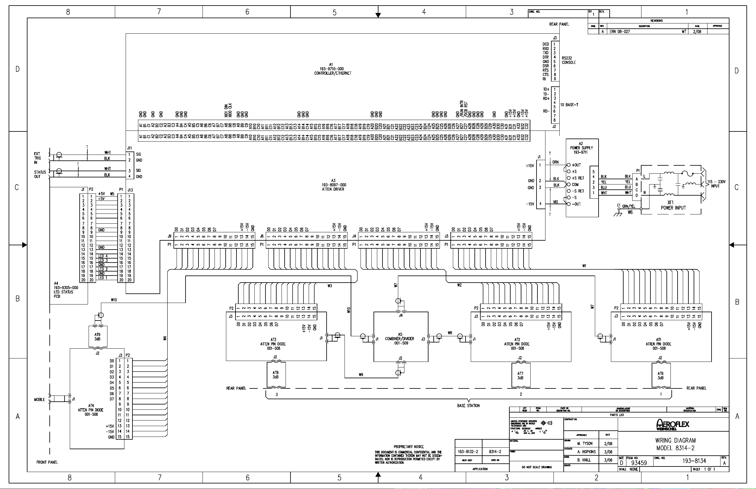
Page 43

Page 44

Page 45

APPENDIX A
APPENDIX A
CARE AND HANDLING OF MICROWAVE COAXIAL
CABLE ASSEMBLIES
A-1 CARE AND HANDLING OF ASSEMBLIES.
To ensure accurate measurements and optimal
performance of Weinschel products, the microwave coaxial
cable assemblies used in system and test setups must be
properly used and maintained. Proper connections, routine
inspection of all cables, and cleaning of the connectors are
extremely important procedures which can prolong the
longevity and accuracy of equipment.
A-2
CABLE INSPECTION.
Routinely check external cables for signs of cracked
insulation, dents, twists, flattening, signs of jacket abrasion, or
other signs of abuse. Wrinkles in the jacket indicate that the
minimum bend radius has been exceeded. Most often, this
occurs near the marker tubes and connectors.
Also inspect the connector interfaces for the following:
•
Bent pins (male).
•
Bent or missing tines (female).
•
Worn or chipped plating.
•
Damaged or displaced dielectric inserts.
•
Thread damage.
•
Folded or mushroomed outer interface rims.
•
Mushroomed pin shoulders (male) or tine ends
(female).
•
Score lines on pins and outer interface rims
visible to the unaided eye.
•
Recessed or protruding pins.
It is advisable to clean the connectors prior to inspection to
make subtle damage more apparent. If any of the above is
noted, replace the assembly before its further use results in
equipment damage. Also inspect the mating connectors for
similar damage.
Inspect the connector interface for signs of debris. Debris
may be in the form of:
•
Plating chips or other metal particles.
•
Dust or dirt.
•
Oily films.
•
Other miscellaneous foreign particles.
If signs of debris are present, clean the connector interface
as directed in Paragraph A-6.
A-3
MAKING INITIAL CONNECTIONS.
Exercise caution when mating cables. Poor connections
lead to poor system performance. They can also damage not
only the cable assembly, but more significantly, front or rear
panel connectors on the equipment itself which may be more
difficult to repair.
A-3.1 ALIGNING CONNECTORS.
lines of two connectors before actual mating. Male retaining
nuts contain a small amount of necessary play which may make
it possible to mate the threads without the pins being properly
aligned. Pin misalignment can damage pins and dielectric
inserts.
A-3.2 MATING CONNECTORS.
connectors by hand, taking care not to force the coupling nut
at the slightest resistance. It is often possible to feel whether
or not the pins are mated. If the coupling nut is difficult to
turn, either the pins are not mated, the coupling nut is
cross-threaded, or one of the connectors has been damaged by
excess torque.
Never hold a male connector coupling nut
stationary while screwing a female connector into it. This
rotation can erode the plating and damage both the outer
interface rim as well as the pin. If the pins become locked,
serious damage can result to both the equipment and the cable
assembly.
A-4
ENSURING PROPER CONNECTOR TORQUE.
A-4.1 OVERTORQUING.
properly mated, apply only the proper amount of torque.
Overtorquing damages both connectors involved. Also, a
connector which has been damaged by overtorquing, in turn,
damages every connector to which it is subsequently mated.
It usually leads to poor system performance as well.
Overtorque can cause:
•
Bent pins.
•
Recessed or protruding pins.
•
Recessed or protruding dielectrics.
•
Chipped plating.
•
Damaged coupling threads.
•
Coupling nut retaining ring damage.
•
Mushroomed outer interface shells.
•
Mushroomed pin shoulders.
Once connectors have been
Align the center
Gently mate the
A-i
Page 46

CARE & HANDLING OF COAXIAL CABLES
A-4.2 HEX-NUT TYPES.
To mate a connector of the
hex-nut type, always use a torque wrench set to the correct
torque value. Tighten the connector slowly until the wrench
snaps. Tightening too quickly can cause the wrench to exceed
its set limit. Do not snap the wrench more than once as this
also causes overtorque.
A-4.3 KNURLED NUTS.
Tighten connectors with
knurled nuts by hand. If this does not provide sufficient
tightness use a hex-nut connector and torque wrench instead.
Never use pliers to tighten a connector. Table A-1
recommends torque specifications for the various types of
connectors.
Table A-1. Recommended Torque Values
Connector Recommended
Torque
GPC-7 (7mm) w/hex nut 14 in/lbs ± 1 in/lbs
Type N w/hex nut 14 in/lbs ± 1 in/lbs
SMA, 2.92mm, 3.5mm 7.5 in/lbs ± 0.5 in/lbs
2.4mm, WPM, WPM-3
WPM-4
Type N & TNC (knurled) Hand-tight
BNC (knurled) Hand-tight
A-5.1 SECURING CABLES.
Use toothed, rubber-lined
"P-clamps" to hold cables in place. If it is necessary to use
tie-wraps, use the widest possible wrap and the lowest setting
on the gun to ensure the minimum pressure on the cable.
A-5.2 STORING CABLES.
When storing cables,
minimize cable "set" by coiling them in large diameters (1 or
2 feet). Unroll the cable properly when it is ready to be used;
do not pull the loops out hastily. Similarly, re-roll them when
storing them away again.
A-6
CLEANING CONNECTOR INTERFACES.
Use the following guidelines in cleaning connector
interfaces:
a. Do not use chlorinated solvents including common tap
water. These solvents are extremely penetrating and
sometimes ruin otherwise good devices and assemblies.
b. Moisten a cotton swab with isopropyl alcohol. Roll
the swab on a paper towel to remove excess.
c. Use the moistened cotton swab to wipe away debris.
Do not try to dissolve the debris by overwetting the swab.
d. Repeat the cleaning process using additional swabs as
necessary. If metallic particles are embedded in the
dielectric, use an eyeglass and a sharp pick in an attempt
to dislodge them. Swab again.
A-5
PROPER CABLE HANDLING.
Never exceed the minimum bend radius specified for a
cable. Guard against tight bends at the end of connector strain
relief tubing, or at the ends of marker tubing where they may
be less noticeable. Although cable bend may seem slight, the
actual radius of the bend at the point of angular departure may
be far smaller than the acceptable radius.
Never pinch, crush or drop objects on cable assemblies.
Also, do not drag a cable over sharp edges as this will pinch it
and cause it to exceed the minimum bend radius.
Never use a cable assembly to pull a piece of equipment.
Cables and connectors are not designed to support or move
equipment.
e. When satisfied that the interfaces are clean, blow them
dry with dry compressed air, or preferably dry nitrogen
(pressurized spray cans work well). Do not use breath.
f. Clean the mating connectors. These may be the source
of the debris.
A-ii
 Loading...