

Page 1

RF POWER METER
6960B
Aeroflex. 2004
No part of this book may be reproduced or transmitted in any form
or by any means, electronic or mechanical, including photocopying,
or recorded by any information storage or retrieval system, without
permission in writing by Aeroflex International Ltd
(hereafter referred to throughout this manual as ’Aeroflex’).
Printed in the UK
Manual part no. 46882/124
Issue 13
23 December 2004
Page 2

Contents
Precautions.........................................................................................................................................iii
Précautions.........................................................................................................................................vi
Vorsichtsmaßnahmen........................................................................................................................ix
Precauzioni........................................................................................................................................xii
Precauciones......................................................................................................................................xv
Chapter 1 GENERAL INFORMATION...........................................................................1-1
Chapter 2 INSTALLATION...............................................................................................2-1
Chapter 3 OPERATION...................................................................................................... 3-1
Chapter 3-1 GPIB OPERATION......................................................................................... 3-17
Chapter 3-2 APPLICATIONS.............................................................................................. 3-29
Chapter 4 BRIEF TECHNICAL DESCRIPTION............................................................4-1
Index ......................................................................................................................... Ind.-1
List of tables................................................................................................... Ind.-3
List of figures................................................................................................. Ind.-3
ii
Page 3
Precautions
These terms have specific meanings in this manual:
WARNING
information to prevent personal injury.
information to prevent damage to the equipment.
important general information.
Symbols
The meaning of the safety related symbols appearing on the equipment and in the
documentation are as follows:-
Symbol Description
Refer to the instruction manual when this symbol is marked on
the instrument. Familiarise yourself with the nature of the
hazard and the actions which may have to be taken.
Dangerous voltage
Toxic hazard
General conditions of use
This product is designed and tested to comply with the requirements of IEC/EN61010-1
‘Safety requirements for electrical equipment for measurement, control and laboratory use’, for
Class I portable equipment and is for use in a pollution degree 2 environment. The equipment is
designed to operate from an installation category I or II supply.
Equipment should be protected from the ingress of liquids and precipitation such as rain,
snow, etc. When moving the equipment from a cold to a hot environment, it is important to
allow the temperature of the equipment to stabilise before it is connected to the supply to avoid
condensation forming. The equipment must only be operated within the environmental
conditions specified in Chapter 1 ‘Performance data’ in the Operating manual, otherwise the
protection provided by the equipment may be impaired.
This product is not approved for use in hazardous atmospheres or medical applications. If
the equipment is to be used in a safety-related application, e.g. avionics or military applications,
the suitability of the product must be assessed and approved for use by a competent person.
WARNING
Electrical hazards (AC supply voltage)
This equipment conforms with IEC Safety Class I, meaning that it is provided with a
protective grounding lead. To maintain this protection the supply lead must always be connected
to the source of supply via a socket with a grounded contact.
Be aware that the supply filter contains capacitors that may remain charged after the
equipment is disconnected from the supply. Although the stored energy is within the approved
iii
Page 4
safety requirements, a slight shock may be felt if the plug pins are touched immediately after
removal.
Do not remove instrument covers as this may result in personal injury. There are no user-
serviceable parts inside.
Refer all servicing to qualified personnel. See list of Service Centers at rear of manual.
Fuses
Note that there are supply fuses in both the live and neutral wires of the supply. If only
one of these fuses should rupture, certain parts of the equipment could remain at supply potential.
WARNING
commensurate with the current requirements of this equipment. See under ‘Performance data’ in
Chapter 1 for power requirements.
WARNING
which give off toxic fumes if incinerated. Take appropriate precautions, therefore, in the disposal
of these items.
WARNING
incinerated or disposed of in normal waste.
since this might cause the battery to vent, overheat or explode.
Fire hazard
Make sure that only fuses of the correct rating and type are used for replacement.
If an integrally fused plug is used on the supply lead, ensure that the fuse rating is
Toxic hazards
Some of the components used in this equipment may include resins and other materials
Lithium
A Lithium battery (or a Lithium battery contained within an IC) is used in this equipment.
As Lithium is a toxic substance, the battery should in no circumstances be crushed,
Do not attempt to recharge this type of battery. Do not short circuit or force discharge
WARNING
other equipment on top of it.
Tilt facility
When the equipment is in the tilt position, it is advisable, for stability reasons, not to stack
LCD handling
When operating or servicing this equipment take care not to depress the front or rear faces
of the display module as this may damage the liquid crystal display elements.
iv
Page 5
Static Sensitive Components
This equipment contains static sensitive components which may be damaged by handling
- refer to the Maintenance part of the Service Manual for handling precautions.
Suitability for use
This equipment has been designed and manufactured by Aeroflex to make RF power
measurements.
If the equipment is not used in a manner specified by Aeroflex, the protection provided by
the equipment may be impaired.
Aeroflex has no control over the use of this equipment and cannot be held responsible for
events arising from its use other than for its intended purpose.
v
Page 6
Précautions
Les termes suivants ont, dans ce manuel, des significations particulières:
WARNING
contient des informations pour éviter toute blessure au personnel.
contient des informations pour éviter les dommages aux équipements.
contient d’importantes informations d’ordre général.
Symboles
La signification des symboles liés à cet équipement est la suivante:
Symbole Nature du risque
Reportez-vous au manuel d’utilisation quand ce symbole
apparaît sur l'instrument. Familiarisez-vous avec la nature du
danger et la conduite à tenir.
Tension dangereuse
Danger produits toxiques
Conditions générales d’utilisation
Ce produit a été conçu et testé pour être conforme aux exigences des normes
CEI/EN61010-1 : 2001 “Règles de sécurité pour appareils électriques de mesurage, de régulation
et de laboratoire”, pour des équipements Classe I portables, qui tiennent dans la main> et pour
une utilisation dans un environnement de pollution de niveau 2. Cet équipement est conçu pour
fonctionner à partir d’une alimentation de catégorie I ou II.
Cet équipement doit être protégé de l’introduction de liquides ainsi que des précipitations
d’eau, de neige, etc... Lorsqu’on transporte cet équipement d’un environnement chaud vers un
environnement froid, il est important de laisser l’équipement se stabiliser en température avant de
le connecter à une alimentation afin d’éviter toute formation de condensation. L'appareil doit être
utilisé uniquement dans le cadre des conditions d'environnement spécifiées au chapitre 1
"Performance data" du manuel d'utilisation, toute autre utilisation peut endommager les systèmes
de protection.
Ce produit n’est pas garanti pour fonctionner dans des atmosphères dangereuses ou pour
un usage médical. Si l'équipement doit être utilisé pour des applications en relation avec la
sécurité, par exemple des applications militaires ou aéronautiques, la compatibilité du produit
doit être établie et approuvée par une personne compétente.
WARNING
Sécurité électrique (tension d’alimentation alternative)
Cet appareil est protégé conformément à la norme CEI de sécurité Classe 1, c’est-à-dire
que sa prise secteur comporte un fil de protection à la terre. Pour maintenir cette protection, le
câble d’alimentation doit toujours être branché à la source d’alimentation par l’intermédiaire
d’une prise comportant une borne de terre.
vi
Page 7
Notez que les filtres d’alimentation contiennent des condensateurs qui peuvent encore être
chargés lorsque l’appareil est débranché. Bien que l’énergie contenue soit conforme aux
exigences de sécurité, il est possible de ressentir un léger choc si l’on touche les bornes sitôt
après débranchement.
Ne démontez pas le capot de l'instrument, car ceci peut provoquer des blessures. Il n'y a
pas de pièces remplaçables par l'utilisateur à l'intérieur.
Faites effectuer toute réparation par du personnel qualifié. Contacter un des Centres de
Maintenance Internationaux dans la liste jointe à la fin du manuel.
Fusibles
Notez qu’il y a deux fusibles, l’un pour la phase et l’autre pour le neutre du câble
d’alimentation. Si un seul fusible est coupé, certaines parties de l’appareil peuvent rester au
potentiel d’alimentation.
WARNING
Risque lié au feu
valeur est compatible avec les besoins en courant de l’appareil. Pour la consommation, reportezvous au “Performance data” dans le chapitre 1.
WARNING
Danger produits toxiques
matières qui dégagent des fumées toxiques lors de leur incinération. Les précautions d’usages
doivent donc être prises lorsqu’on se débarrasse de ce type de composant.
WARNING
Lithium
équipement.
jeter avec des déchets normaux.
décharge de la pile car cela pourrait causer une fuite, une surchauffe ou une explosion.
Lors du remplacement des fusibles vérifiez l’exactitude de leur type et de leur valeur.
Si le câble d’alimentation comporte une prise avec fusible intégré, assurez vous que sa
Certains composants utilisés dans cet appareil peuvent contenir des résines et d’autres
Une pile au Lithium ou un CI contenant une pile au Lithium est utilisé dans cet
Le Lithium étant une substance toxique, il ne faut en aucun cas l’écraser, l’incinérer ou le
N’essayez pas de recharger ce type de pile. Ne court-circuitez pas ou ne forcez pas la
WARNING
Position inclinée
stabilité, de ne pas y empiler d’autres appareils.
Lorsque l’appareil est dans une position inclinée, il est recommandé, pour des raisons de
vii
Page 8

Utilisation
Cet équipement a été conçu et fabriqué par Aeroflex pour effectuer des mesures de
puissance RF
La protection de l'équipement peut être altérée s'il n'est pas utilisé dans les conditions
spécifiées par Aeroflex.
Aeroflex n'a aucun contrôle sur l'usage de l'instrument, et ne pourra être tenu pour
responsable en cas d'événement survenant suite à une utilisation différente de celle prévue.
viii
Page 9
Vorsichtsmaßnahmen
Diese Hinweise haben eine bestimmte Bedeutung in diesem Handbuch:
WARNING
dienen zur Vermeidung von Verletzungsrisiken.
dienen dem Schutz der Geräte.
enthalten wichtige Informationen.
Symbole
Die Gefahrensymbole auf den Geräten sind wie folgt:
Symbol Gefahrenart
Beziehen Sie sich auf die Bedienungsanleitung wenn das
Messgerät mit diesem Symbol markiert ist. Machen Sie sich
mit der Art der Gefahr und den Aktionen die getroffen
werden müssen bekannt.
Gefährliche Spannung
Warnung vor giftigen Substanzen
Allgemeine Hinweise zur Verwendung
Dieses Produkt wurde entsprechend den Anforderungen von IEC/EN61010-1
“Sicherheitsanforderungen für elektrische Ausrüstung für Meßaufgaben, Steuerung und
Laborbedarf”, Klasse I transportabel zur Verwendung in einer Grad 2 verunreinigten Umgebung,
entwickelt und getestet. Dieses Gerät ist für Netzversorgung Klasse I oder II zugelassen.
Das Gerät sollte vor dem Eindringen von Flüssigkeiten sowie vor Regen, Schnee etc.
geschützt werden. Bei Standortänderung von kalter in wärmere Umgebung sollte das Gerät
wegen der Kondensation erst nach Anpassung an die wärmere Umgebung mit dem Netz
verbunden werden. Das Gerät darf nur in Umgebungsbedingungen wie in Kapitel 1
"Leistungsdaten (Performance data)" der Bedienungsanleitung beschrieben, betrieben werden;
ansonsten wird der vom Gerät vorgesehene Schutz des Anwenders beeinträchtigt.
Dieses Produkt ist nicht für den Einsatz in gefährlicher Umgebung (z.B. Ex-Bereich) und
für medizinische Anwendungen geprüft. Sollte das Gerät für den Einsatz in sicherheitsrelevanten
Anwendungen wie z.B. im Flugverkehr oder bei militaerischen Anwendungen vorgesehen sein,
so ist dieser von einer für diesen Bereich zuständigen Person zu beurteilen und genehmigen.
WARNING
Elektrische Schläge (Wechselspannungsversorgung)
Das Gerät entspricht IEC Sicherheitsklasse 1 mit einem Schutzleiter nach Erde. Das
Netzkabel muß stets an eine Steckdose mit Erdkontakt angeschlossen werden.
Filterkondensatoren in der internen Spannungsversorgung können auch nach
Unterbrechung der Spannungszuführung noch geladen sein. Obwohl die darin gespeicherte
ix
Page 10
Energie innerhalb der Sicherheitsmargen liegt, kann ein leichter Spannungsschlag bei Berührung
kurz nach der Unterbrechung erfolgen.
Öffnen Sie niemals das Gehäuse der Geräte das dies zu ernsthaften Verletzungen führen
kann. Es gibt keine vom Anwender austauschbare Teile in diesem Gerät.
Lassen Sie alle Reparaturen durch qualifiziertes Personal durchführen. Eine Liste der
Servicestellen finden Sie auf der Rückseite des Handbuches.
Sicherungen
Es ist zu beachten, daß es Sicherungen in beiden (spannunsführenden und neutralen)
Zuleitungen gibt. Wenn nur eine von diesen Sicherungen schmilzt, so bleiben einige Geräteteile
immer noch auf Spannungspotential.
WARNING
Feuergefahr
entsprechend der Stromaufnahme des Gerätes verwendet werden. Siehe hierzu die
Leistungsdaten (Performance data) in Kapitel 1.
WARNING
Warnung vor giftigen Substanzen
enthalten sein, die im Brandfall giftige Gase erzeugen. Bei der Entsorgung müssen deshalb
entsprechende Vorsichtsmaßnahmen getroffen werden.
WARNING
Lithium
eingebaut.
überhitzt werden und explodieren kann.
Es dürfen nur Ersatzsicherungen vom gleichen Typ mit den korrekten Spezifikationen
In einigen Bauelementen dieses Geräts können Epoxyharze oder andere Materialien
Eine Lithium Batterie oder eine Lithium Batterie innerhalb eines IC ist in diesem Gerät
Da Lithium ein giftiges Material ist, sollte es als Sondermüll entsorgt werden.
Diese Batterie darf auf keinen Fall geladen werden. Nicht kurzschließen, da sie dabei
WARNING
Schrägstellung
gestellt werden.
x
Bei Schrägstellung des Geräts sollten aus Stabilitätsgründen keine anderen Geräte darauf
Page 11

Eignung für Gebrauch
Dieses Gerät wurde von Aeroflex entwickelt und hergestellt um HF Leistungsmessungen
durchzuführen
Sollte das Gerät nicht auf die von Aeroflex vorgesehene Art und Weise verwendet
werden, kann die Schutzfunktion des Gerätes beeinträchtigt werden.
Aeroflex hat keinen Einfluß auf die Art der Verwendung und übernimmt keinerlei
Verantwortung bei unsachgemässer Handhabung.
xi
Page 12
Precauzioni
Questi termini vengono utilizzati in questo manuale con significati specifici:
WARNING
riportano informazioni atte ad evitare possibili pericoli alla persona.
riportano informazioni per evitare possibili pericoli all’apparecchiatura.
riportano importanti informazioni di carattere generale.
Simboli
Significato dei simboli di pericolo utilizzati nell’apparato:
Simbolo Tipo di pericolo
Fare riferimento al manuale operativo quando questo
simbolo è riportato sullo strumento. Rendervi conto della
natura del pericolo e delle precauzioni che dovrete
prendere.
Tensione pericolosa
Pericolo sostanze tossich e
Condizioni general i d’uso
Questo prodotto è stato progettato e collaudato per rispondere ai requisiti della direttiva
IEC/EN61010-1 ‘Safety requirements for electrical equipment for measurement, control and
laboratory use’ per apparati di classe I portatili e per l’uso in un ambiente inquinato di grado 2.
L’apparato è stato progettato per essere alimentato da un alimentatore di categoria I o II.
Lo strumento deve essere protetto dal possibile ingresso di liquidi quali, ad es., acqua,
pioggia, neve, ecc. Qualora lo strumento venga portato da un ambiente freddo ad uno caldo, è
importante lasciare che la temperatura all’interno dello strumento si stabilizzi prima di
alimentarlo per evitare formazione di condense. Lo strumento deve essere utilizzato
esclusivamente nelle condizioni ambientali descritte nel capitolo 1 ‘Performance data’ del
manuale operativo,
in caso contrario le protezioni previste nello strumento potrebbero risultare
non sufficienti.
Questo prodotto non è stato approvato per essere usato in ambienti pericolosi o
applicazioni medicali. Se lo strumento deve essere usato per applicazioni particolari collegate
alla sicurezza (per esempio applicazioni militari o avioniche), occorre che una persona o un
istituto competente ne certifichi l'uso.
WARNING
Pericoli da elettricità (alimentazione c.a.)
Quest ’apparato è provvisto del collegamento di protezione di terra e rispetta le norme di
sicurezza IEC, classe 1. Per mantenere questa protezione è necessario che il cavo, la spina e la
presa d’alimentazione siano tutti provvisti di terra.
xii
Page 13
Il circuito d’alimentazione contiene dei filtri i cui condensatori possono restare carichi
anche dopo aver rimosso l’alimentazione. Sebbene l’energia immagazzinata è entro i limiti di
sicurezza, purtuttavia una leggera scossa può essere avvertita toccando i capi della spina subito
dopo averla rimossa.
Non rimuovete mai le coperture perché così potreste provocare danni a voi stessi. Non vi
sono all’interno parti di interesse all’utilizzatore.
Tutte gli interventi sono di competenza del personale qualificato. Vedi elenco
internazionale dei Centri di Assistenza in fondo al manuale.
Fusibili
Notare che entrambi i capi del cavo d’alimentazione sono provvisti di fusibili. In caso di
rottura di uno solo dei due fusibili, alcune parti dello strumento potrebbero restare sotto tensione.
WARNING
Pericolo d’incendio
tipo prescritti.
requisiti di alimentazione richiesti dallo strumento. Tali requisiti sono riportati nel cap. 1
“Performance data”.
WARNING
Pericolo sostanze tossiche
materiali che, se bruciati, possono emettere fumi tossici. Prendere quindi le opportune
precauzioni nell’uso di tali parti.
WARNING
Litio
batteria al litio.
incenerita, né gettata tra i normali rifiuti.
forzata. Queste azioni possono provocare surriscaldamento, fuoriuscita di gas o esplosione della
batteria.
Assicurarsi che, in caso di sostituzione, vengano utilizzati solo fusibili della portata e del
Se viene usata una spina con fusibili, assicurarsi che questi siano di portata adeguata ai
Alcuni dei componenti usati in questo strumento possono contenere resine o altri
Quest ’apparato incorpora una batteria al litio o un circuito integrato contenente una
Poiché il litio è una sostanza tossica, la batteria non deve essere mai né rotta, né
Questo tipo di batteria non può essere sottoposto né a ricarica né a corto-circuito o scarica
WARNING
Posizionamento inclinato
sovrapporre altri strumenti.
Quando lo strumento è in posizione inclinata è raccomandato, per motivi di stabilità, non
xiii
Page 14

Caratteristiche d’uso
Questo strumento è stato progettato e prodotto da Aeroflex eseguire misure di potenza in
RF
Se lo strumento non è utilizzato nel modo specificato da Aeroflex, le protezioni previste
sullo strumento potrebbero risultare inefficaci.
Aeroflex non può avere il controllo sull’uso di questo strumento e non può essere ritenuta
responsabile per eventi risultanti da un uso diverso dallo scopo prefisso.
xiv
Page 15

Precauciones
Estos términos tienen significados específicos en este manual:
WARNING
contienen información referente a prevención de daños personales.
contienen información referente a prevención de daños en equipos.
contienen información general importante.
Símbolos
Los significados de los símbolos de peligro que aparecen en los equipos son los
siguientes:
Símbolo Naturaleza del peligro
Vea el manual de funcionamiento cuando este símbolo
aparezca en el instrumento. Familiarícese con la naturaleza
del riesgo y con las acciones que deban de tomarse.
Voltaje peligroso
Aviso de toxicidad
Condiciones generales de uso
Este producto ha sido diseñado y probado para cumplir los requerimientos de la
normativa IEC/EN61010-1 “Requerimientos de la normativa para equipos eléctricos de medida,
control y uso en laboratorio”, para equipos clase I portátiles y para uso en un ambiente con un
grado de contaminación 2. El equipo ha sido diseñado para funcionar sobre una instalación de
alimentación de categorías I o II.
Debe protegerse el equipo de la entrada de líquidos y precipitaciones como nieve, lluvia,
etc. Cuando se traslada el equipo de entorno frío a un entorno caliente, es importante aguardar la
estabilización el equipo para evitar la condensación. Sólo debe utilizarse el aparato en las
condiciones ambientales especificadas en el capítulo 1 “Especificaciones” o “Performance data”
del Manual de Operación/Funcionamiento, en caso contrario la propia protección del equipo
puede resultar dañada.
Este producto no ha sido aprobado para su utilización en entornos peligrosos o en
aplicaciones médicas. Si se va a utilizar el equipo en una aplicación con implicaciones en cuanto
a seguridad, como por ejemplo aplicaciones de aviónica o militares, es preciso que un experto
competente en materia de seguridad apruebe su uso.
WARNING
Nivel peligroso de electrici dad (tensi ón de red)
Este equipo cumple las normas IEC Seguridad Clase 1, lo que significa que va provisto de
un cable de protección de masa. Para mantener esta protección, el cable de alimentación de red
debe de conectarse siempre a una clavija con terminal de masa.
xv
Page 16
Tenga en cuenta que el filtro de red contiene condensadores que pueden almacenar carga
una vez desconectado el equipo. Aunque la energía almacenada está dentro de los requisitos de
seguridad, pudiera sentirse una ligera descarga al tocar la clavija de alimentación inmediatamente
después de su desconexión de red.
No retire las cubiertas del chasis del instrumento, ya que pudiera resultar dañado
personalmente. No existen partes que puedan ser reparadas en su interior.
Deje todas las tareas relativas a reparación a un servicio técnico cualificado. Vea la lista
de Centros de Servicios Internacionales en la parte trasera del manual.
Fusibles
Se hace notar que el Equipo está dotado de fusibles tanto en el acti vo como el neutro de
alimentación. Si sólo uno de estos fusibles fundiera, existen partes del equipo que pudieran
permanecer a tensión de red.
WARNING
Peligro de incendio
corresponden a los requeridos por el equipo. Ver sección de especificaciones del capítulo 1 para
comprobar los requisitos de alimentación.
WARNING
Aviso de toxicidad
de materiales que al arder produjeran sustancias tóxicas, Por tanto, tome las debidas
precauciones en la manipulación de esas piezas.
WARNING
Litio
Asegúrese de utilizar sólo fusibles del tipo y valores especificados como repuesto.
Si se utiliza una clavija con fusible incorporado, asegúrese de que los valores del fusible
Alguno de los componentes utilizados en este equipo pudieran incluir resinas u otro tipo
En este equipo se utiliza una batería de litio (o contenida dentro de un CI).
Dada que el litio es una substancia tóxica las baterías de este material no deben ser
aplastadas, quemadas o arrojadas junto a basuras ordinarias.
No trate de recargar este tipo de baterías. No las cortoci rcuite o fuerce su descarga ya que
puede dar lugar a que la esta emita gases, se recaliente o explote.
WARNING
Tener en cuenta con el equipo inclinado
apilar otros equipos encima de él.
xvi
Si utiliza el equipo en posición inclinada, se recomienda, por razones de estabilidad, no
Page 17

Idoneidad de uso
Este equipo ha sido diseñado y fabricado por Aeroflex para realizar medidas de potencia
de RF
Si el equipo fuese utilizado de forma diferente a la especificada por Aeroflex, la
protección ofrecida por el equipo pudiera quedar reducida.
Aeroflex no tiene control sobre el uso de este equipo y no puede, por tanto, exigirsele
responsabilidades derivadas de una utilización distinta de aquellas para las que ha sido diseñado.
xvii
Page 18

Page 19
Page 20
Page 21
Page 22
Page 23
Page 24

Page 25

GENERAL INFORMATION
±
ge
±
n
ch
L
s)
o
ge
Power reference
Frequency: 50 MHz ±0.25 MHz.
Power: 1 mW.
Uncertainty: ±0.7%, traceable to national standards.
Accuracy: ±1.2% worst case for 1 year.
Instrumentation accuracy
Watts mode: ±0.5%.
dBm mode: ±0.02% dB.
dB REL mode: ±0.02% dB.
Zero
Set:
1% of full scale on most sensitive range (ran
1).
Carry over: ±0.03% of full scale (when zeroed on range 1).
Drift:
(Over 1 h at constant temperature after
24 h stabilization)
0.01% of full scale (±2% for 6920 series) o
range 1, decreasing by a factor of 10 for ea
higher range.
Noise
ess than 1% of full scale (2% for 6920 serie
n the most sensitive range with an avera
factor greater than 19 over a 10 s period.
Outputs
Fast levelling: Proportional to indicated power. For external
levelling of an RF source.
0 to 1 V, each range. 1 kΩ output impedance.
(Excludes Cal. Factor, Linearity Factor and
Average Number).
Recorder: Proportional to indicated power. ±1.0%.
In dB mode: 1 V/decade, 7 V max on range 5.
In Watts mode: 0 to 5 V linear, each range.
Blanking: Max voltage: 25 V
Max current: 50 mA open collector, short
circuit for blanking during AUTO ZERO.
Response time:
Range 1 (most sensitive): 1 second, selectable.
Ranges 2 to 5: 250 ms (display update).
25 ms selectable using GPIB.
46882-124Y 1-7
Page 26

GENERAL INFORMATION
C
e
GPIB interface (Option 001)
All front panel functions are remotely
programmable except for test modes.
Complies with the following sub-sets of IEEE
488-1978: SH1, AH1, T5, L4, SR1, RL1, DC1,
DT1, E1.
Limit range of operation
Temperature: 0°C to 55°C.
Conditions of storage and transport
Temperature: -40°C to +70°C.
Humidity: Up to 95% RH at 35°C.
Altitude: Up to 2500 m (pressurized freight at 27 kPa
differential, i.e. 3.9 lbf/in
Electromagnetic compatability
onforms with the protection requirements of th
EEC Council Directive 89/336/EEC.
Conforms with the limits specified in the
2
following standards:
IEC/EN61326-1 : 1997, RF Emission Class B,
Immunity Table 1, Performance Criterion B
Safety
Conforms with the requirements of EEC Council
Directive 73/23/EEC and Standards IEC/EN
61010-1 : 2001 + C1 : 2002 + C2 : 2003.
This instrument is designed to comply with the
requirements of IEC/EN61010-1 for Class I
portable equipment and is for use in a pollution
degree 2 environment. The equipment is
designed to operate from installation supply
categories I or II.
Power requirements
AC supply: Switchable voltage ranges:
105 V - 120 V~ (limit 90 - 132 V~)
210 V to 240 V~ (limit 188 - 264 V~)
Frequency: 50 Hz to 400 Hz (Limit 45 - 440 Hz).
Power consumption: 50 VA maximim.
DC supply (Option 004): Input voltage: Operates from 11 V to 32 V DC.
The instrument resets below 11 V
Power consumption: 20 W maximum.
Dimensions and weight: Height: 108 mm (including feet),
88 mm (excluding feet).
Width: 256 mm (including handle),
216 mm (excluding handle).
Length: 369 mm (overall).
Weight: 3.3 kg.
1-8 46882-124Y
Page 27

GENERAL INFORMATION
VERSIONS, ACCESSORIES AND ASSOCIATED EQUIPMENT
Options
GPIB Option 001
Rear panel sensor input Option 002
Top cover mounted storage pouch Option 003
External DC operation Option 004
Supplied accessories Order code
Operating manual 46882/124
Operating summary card 46882/123
AC supply lead 2 metre power sensor cable 06950/081
DC supply lead (DC input versions) 43138/154
Optional accessories Order code
GPIB manual (details of general GPIB protocols) 46881/365
Maintenance manual for 6960B 46882/125
GPIB IEEE/IEC connector adapter 46883/408
5 metre power sensor cable 06950/086
15 metre power sensor cable 06950/087
50 metre power sensor cable 06950/088
Rack mounting kit (double unit - 3 U high) 46884/501
Rack mounting kit (single unit - 2 U high) 46884/500
Stowage cover 54124/022
Associated equipment
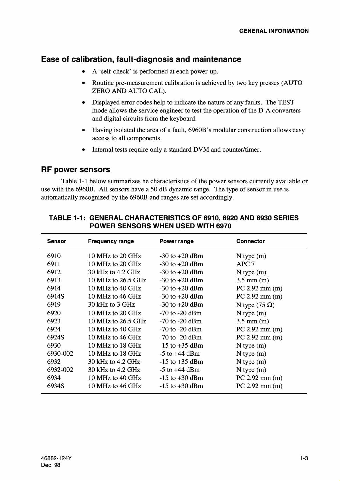
RF Power Sensors 6910, 6920 and 6930 Series. See Table 1-1.
46882-124Y 1-9
Page 28

Page 29

EC Declaration of Conformity
Certificate Ref. No.: DC217
The undersigned, representing:
GENERAL INFORMATION
Manufacturer:
Address:
Aeroflex International Ltd.
Longacres House, Six Hills Way,
Stevenage, Hertfordshire, UK SG1 2AN
Herewith declares that the product:
Equipment Description:
Model No.
Options:
6960B
1, 2, 4
RF Power Meter
is in conformity with the following EC directive(s)
(including all applicable amendments)
Reference No.
73/23/EEC
89/336/EEC
Title:
Low Voltage Directive
EMC Directive
and that the standards and/or technical specifications referenced below have been applied:
Safety:
IEC/EN61010-1 : 2001 + C1 : 2002 + C2 : 2003
EMC:
IEC/EN 61326-1:1997 + A1 : 1998 + A2 : 2001
RF Emission Class B, Immunity Table 1 and Performance Criterion B
Qualifying Notes:
Aeroflex Stevenage
(Signature)
Robert Trott — Director of Product Assurance
(Place)
23 December 2003
(Date)
46882-124Y 1-11
Page 30

Page 31

Chapter 2
INSTALLATION
Unpacking and repacking ... ... ... 2-1
Mounting arrangements ... ... ... 2-2
Class I power cords (3-core) ... ... ... 2-2
Connecting to AC supply ... ... ... 2-4
Routine safety testing and inspection ... ... 2-4
GPIB interface ... ... ... 2-6
Rack mounting kits ... ... ... 2-6
UNPACKING AND REPACKING
Contents
Page
Retain the packing materials and the packing instructions note (if included) in case it is
necessary to reship the instrument.
If the instrument is to be returned for servicing attach a label indicating the service
required, type or model number (on rear label), serial number and your return address. Pack the
instrument in accordance with the general instructions below or with the more detailed
information in the packing instruction note.
(1) Place a pad in the bottom of the container.
(2) Place pads in the front and rear ends of the container with the plywood load
spreader(s) facing inwards.
(3) Put the polythene over the instrument and place it in the container with the front
handles and rear projections (where applicable) against the plywood load spreaders.
(4) Place pads in the two sides of the container with cushioning facing inwards.
(5) Place the top pad in position.
(6) Wrap the container in waterproof paper and secure with adhesive tape.
(7) Mark the package FRAGILE to encourage careful handling.
Note ...
If the original container or materials are not available, use a strong double-wall carton
packed with a 7 to 10 cm layer of shock absorbing material around all sides of the
instrument to hold it firmly. Protect the front panel controls with a plywood or cardboard
load spreader; if the rear panel has guard plates or other projections a rear load spreader is
also advisable.
46882-124Y 2-1
Page 32

INSTALLATION
MOUNTING ARRANGEMENTS
Excessive temperatures may affect the instrument’s performance, therefore, completely
remove the plastic cover, if one is supplied over the case. Avoid standing the instrument or
associated sensors in the vicinity of large transformers or other possible magnetic fields or where
X-rays are present. If the source of such fields cannot be isolated Mumetal shields should be
used to provide the necessary screening.
CLASS I POWER CORDS (3-CORE)
General
This instrument is a Safety Class 1 product and therefore must be earthed. Use the
supplied power cord or an appropriate replacement. Make sure the instrument is plugged into an
outlet socket with a protective earth contact.
The detachable power cord is the instrument's disconnecting device, but if the instrument
is integrated into a rack or system, an external power switch or circuit breaker is required.
Whichever is the disconnecting device, make sure it can be easily reached by the operator and
that it is accessible at all times.
When the equipment has to be plugged into a Class II (ungrounded) 2-terminal socket
outlet, the cable should either be fitted with a 3-pin Class I plug and used in conjunction with an
adapter incorporating a ground wire, or be fitted with a Class II plug with an integral ground
wire. The ground wire must be securely fastened to ground. Grounding one terminal on a
2-terminal socket will not provide adequate protection.
In the event that a moulded plug has to be removed from a lead, it must be disposed of
immediately. A plug with bare flexible cords is hazardous if engaged in a live socket outlet.
Power cords with the following terminations are available from Aeroflex. Please check
with your local sales office for availability.
British
Country IEC 320 plug type Part number
United Kingdom Straight through 23422/001
United Kingdom Right angled 23422/002
EARTH
NEUTRAL
LIVE
UNITED KINGDOM
The UK lead is fitted with an ASTA approved moulded plug to
BS 1363.
A replaceable 13 A fuse to BS 1362 is contained within the plug. This fuse is only
designed to protect the lead assembly. Never use the plug with the detachable fuse cover omitted
or if the cover is damaged.
The fuse(s) or circuit breaker to protect the equipment is fitted at the back of the
equipment.
C3510
2-2 46882-124Y
Page 33

North American
Country IEC 320 plug type Part number
North American Straight through 23422-004
North American Right angled 23422-005
The North American lead is fitted with a NEMA 5-15P (Canadian
CS22.2 No 42) plug and carries approvals from UL and CSA for use in
the USA and Canada.
Continental Europe
INSTALLATION
NEUTRAL
U.S./CANADA/KOREA
EARTH
LIVE
C3511
Country IEC 320 plug type Part number
Europe Straight through 23422-006
Europe Right angled 23422-007
The Continental European lead is fitted with a right angle IEC83
standard C4 plug (CEE 7/7) which allows it to be used in sockets with
either a male earth pin (standard C 3b) or side earth clips (standard C 2b)
EARTH
NEUTRAL
EARTH
CONTINENTAL
EUROPE
LIVE
C3512
the latter is commonly called the German ‘Schuko’ plug. In common with
other Schuko style plugs, the plug is not polarized when fitted into a Schuko socket. The lead
carries approvals for use in Austria, Belgium, Finland, France, Germany, Holland, Italy, Norway
and Sweden. Note that this plug will not fit Italian standard CEI 23-16 outlets. The lead should
not be used in Denmark given that the earth connection will not be made.
Français
Le câble d'alimentation d'Europe Continentale est muni d'un connecteur mâle à angle
droit type CEI83, standard C4 (CEE 7/7), qui peut être utilisé dans une prise femelle à ergot de
terre (standard C 3b) ou à clips latéraux (standard C 2b), cette dernière étant communément
appelée prise “Schuko” allemande. De la même façon que les autres connecteurs de type Schuko,
celui-ci n'est pas polarisé lorsqu'il s'adapte à une prise femelle Schuko. Ce câble d'alimentation
est homologué en Allemagne, Autriche, Belgique, Finlande, France, Hollande, Italie, Norvège et
Suède. A noter que ce connecteur n'est pas compatible avec les prises de courant italiennes au
standard CEI 23-16. Ce câble ne doit pas être utilisé au Danemark à cause du défaut de
connexion de masse.
Deutsch
Das kontinentaleuropäische Netzkabel ist mit einem rechtwinkeligen Stecker nach IEC83
C4 (CEE7/7) Standard versehen, welcher sowohl in Steckdosen mit Erde-Stift (Standard C 3b)
oder seitlichen Erdeklemmen, im allgemeinen “Schukosteckdose” genannt, paßt. Üblicherweise
ist der Schukostecker bei Verwendung in Schukosteckdosen nicht gepolt. Dieses Netzkabel
besitzt Zulassung für Österreich, Belgien, Finnland, Frankreich, Deutschland, Holland, Italien,
Norwegen und Schweden.
Hinweis: Dieser Schukostecker paßt nicht in die italienischen Standardsteckdosen nach
CEI 23-16 Norm. Dieses Netzkabel sollte nicht in Dänemark verwendet werden, da hier keine
Erdeverbindung hergestellt wird.
46882-124Y 2-3
Page 34

INSTALLATION
Español
El cable de alimentación tipo Europeo Continental dispone de una clavija C4 normalizada
IEC83 (CEE 7/7) que permite su utilización tanto en bases de enchufe con toma de tierra macho
(tipo C 3b) o con toma de tierra mediante contactos laterales (tipo C 2b) que, en este último caso,
suele denominarse “Schuko”. Al igual que cualquier otra clavija tipo Schuko, las conexiones a
red no están polarizadas cuando se conectan a una base tipo Schuko. El cable lleva autorización
para su uso en Austria, Bélgica, Finlandia, Franci a, Alemania, Holanda, Ital ia, Noruega y Suecia.
Observe que este cable no se adapta a la norma italiana CEI 23-16. El cable no debe utilizarse en
Dinamarca en el caso de no efectuarse conexión a tierra.
Italiano
I cavi d'alimentazione per l'Europa continentale vengono forniti terminati con una spina
ad angolo retto del tipo C4 secondo lo standard IEC83 (CEE 7/7) che può essere usato in prese in
cui la terra può essere fornita o tramite connettore maschio (C 3b) o tramite clips laterali (C 2b),
quest'ultima comunemente detta di tipo tedesca “Schuko”. Questa spina, quando collegata ad una
presa Schuko, non è polarizzata.
Il cavo può essere usato in Austria, Belgio, Finlandia, Francia, Germania, Olanda,
Norvegia, Svezia ed Italia. E' da notare che per l'Italia questo non risponde allo standard
CEI 23-16.
Questa spina non dovrebbe invece essere usata in Danimarca in quanto non realizza il
collegamento di terra.
CONNECTING TO AC SUPPLY
Before connecting the instrument to the AC supply, check the position of the voltage
selector switch. The range selected can be seen on the side of the switch protection plate situated
on the rear panel.
The instrument is normally dispatched selected to the 210-240 V range. To select the
105-120 V range remove the protection plate, switch ranges and change the value of the AC
supply fuses to that shown below, reverse and refit the protection plate.
Fuses are 20 mm x 5 mm cartridge type.
115 V range: T500mAL250V
230 V range: T250mAL250V
ROUTINE SAFETY TESTING AND INSPECTION
In the UK, the ‘Electricity at Work Regulations’ (1989) section 4(2) places a requirement
on the users of equipment to maintain it in a safe condition. The explanatory notes call for
regular inspections and tests together with a need to keep records.
The following electrical tests and inspection information is provided for guidance
purposes and involves the use of voltages and currents that can cause injury. It is important that
these tests are only performed by competent personnel.
Prior to carrying out any inspection and tests, the instruments must be disconnected from
the mains supply and all external signal connections removed. All tests should include the
instrument’s own supply lead, all covers must be fitted and the equipment supply switch must be
in the ‘ON’ position.
2-4 46882-124Y
Page 35

INSTALLATION
The recommended inspection and tests fall into three categories and should be carried out
in the following sequence:-
1. Visual inspection
2. Earth bonding tests
3. Insulation resistance test
1. Visual inspection
A visual inspection should be carried out on a periodic basis. This interval is dependent
on the operating environment, maintenance and use, and should be assessed in accordance with
guidelines issued by the Health and Safety Executive (HSE). As a guide, this instrument when
used indoors in a relatively clean environment would be classified as ‘low risk’ equipment and
hence should be subject to safety inspections on an annual basis. If the use of the equipment is
contrary to the conditions specified, you should review the safety re-test interval.
As a guide, the visual inspection should include the following where appropriate:
Check that the equipment has been installed in accordance with the instructions provided
(e.g. that ventilation is adequate, supply isolators are accessible, supply wiring is adequate and
properly routed).
The condition of the mains supply lead and supply connector(s).
Check that the mains supply switch isolates the instrument from the supply.
The correct rating and type of supply fuses.
Security and condition of covers and handles.
Check the supply indicator functions (if fitted).
Check the presence and condition of all warning labels and markings and supplied safety
information.
Check the wiring in re-wireable plugs and appliance connectors.
If any defect is noted this should be rectified before proceeding with the following
electrical tests.
2. Earth bonding tests
Earth bonding tests should be carried out using a 25 A (12 V maximum open circuit
voltage) DC source. Tests should be limited to a maximum duration of 5 seconds and have a
pass limit of 0.1 Ω after allowing for the resistance of the supply lead. Exceeding the test
duration can cause damage to the equipment. The tests should be carried out between the supply
earth and exposed case metalwork, no attempt should be made to perform the tests on functional
earths (e.g. signal carrying connector shells or screen connections) as this will result in damage to
the equipment.
3. Insulation tests
A 500 V DC test should be applied between the protective earth connection and combined
live and neutral supply connections with the equipment supply switch in the ‘on’ position. It is
advisable to make the live/neutral link on the appliance tester or its connector to avoid the
possibility of returning the equipment to the user with the live and neutral poles linked with an
ad-hoc strap. The test voltage should be applied for 5 seconds before taking the measurement.
Aeroflex employs reinforced insulation in the construction of its products and hence a
minimum pass limit of 7 MW should be achieved during this test.
Where a DC power adapter is provided with the equipment, the adapter must pass the
7 MΩ test limit.
46882-124Y 2-5
Page 36

INSTALLATION
We do not recommend dielectric flash testing during routine safety tests. Most portable
appliance testers use AC for the dielectric strength test which can cause damage to the supply
input filter capacitors.
4. Rectification
It is recommended that the results of the above tests are recorded and checked during each
repeat test. Significant differences between the previous readings and measured values should be
investigated.
If any failure is detected during the above visual inspection or tests, the equipment should
be disabled and the fault should be rectified by an experienced Service Engineer who is familiar
with the hazards involved in carrying out such repairs.
Safety critical components should only be replaced with equivalent parts, using
techniques and procedures recommended by Aeroflex.
The above information is provided for guidance only. aeroflex designs and constructs its
products in accordance with International Safety Standards such that in normal use they represent
no hazard to the operator. Aeroflex reserves the right to amend the above information in the
course of its continuing commitment to product safety.
Cleaning
Before commencing any cleaning, switch off the instrument and disconnect it from the
supply. The exterior surface of the case may be cleaned using a soft cloth moistened in water.
Do not use aerosol or liquid solvent cleaners.
Cleaning the LCD Window
To prevent damage to the LCD window, care should be taken not to scratch the surface
during use and also when cleaning. The LCD window should be cleaned by wiping a slightly
damp, soft, lint-free cloth gently over the surface. To remove grease or smears, use a clean
cotton cloth moistened with Heptane. No other cleaning agents should be used. Clean the
window using either horizontal or vertical strokes, NEVER a circular action.
GPIB INTERFACE
The GPIB interface module is available as an optional accessory (no. 03964-650E). This
consists of a kit of parts, complete with fitting instructions.
RACK MOUNTING KITS
(1) For rack mounting the 6960B on its own, a single unit rack mounting kit (no.
46884-500K) is available. This contains a pair of side angle plates wide enough to
allow the instrument o sit centrally within the rack frame.
(2) For rack mounting the 6960B on its own, a single unit rack mounting kit (no.
46884-501A) is available. This kit contains fixings for joining the two instruments
together and for attaching the twinned unit to the rack. A blanking plate is also
supplied for one half of the kit, allowing the 6960B to be mounted alone while
retaining the option of mounting a second instrument beside it.
(3) Rack mounting instructions are supplied with the kits.
2-6 46882-124Y
Page 37

Page 38

Page 39

Page 40

Page 41

Page 42

Page 43

Page 44

Page 45

Page 46

Page 47

Page 48

Page 49

Page 50

Page 51

Page 52

Page 53

Page 54

Page 55

Page 56

Page 57

Page 58

Page 59

Page 60

Page 61

Page 62

Page 63

Page 64

Page 65

Page 66

Page 67

Page 68

Page 69

Page 70

Page 71

Page 72

Page 73

Page 74

Page 75

Page 76

 Loading...