

Page 1

RADIO TEST SET
2965A, 2966A, 2967 & 2968
Operating Manual
Document part no. 46892/274
Page 2

RADIO TEST SET
2965A, 2966A,
2967 and 2968
© Aeroflex International Ltd. 2008
No part of this book may be reproduced or transmitted in
any form or by any means, electronic or mechanical,
including photocopying, or recorded by any information
storage or retrieval system, without permission in writing
by Aeroflex Internation Ltd (hereafter referred to
throughout this document as 'Aeroflex')
Manual part no. 46892/274
Based on Issue 15 of the printed manual
7 January 2008
Page 3

This manual explains how to use the 2965A, 2966A, 2967 and 2968 Radio Test Sets.
It applies to test sets fitted with version 10.2x of software 31779/258 fitted to A6/2.
With the exception of the section User
factory preset settings, prior to any customisation.
Note: colour LCD replaces CRT
Instruments are now fitted with a colour LCD, further enhancing legibility of the
display. Please bear this in mind whenever the text makes reference to ‘CRT’. There
are no changes to the method of operation, and screen formats remain as shown in the
text.
Intended audience
People who need to test radio systems and associated equipment.
Structure
Chapter 1
Provides general information concerning the test set's features, performance, and
accessories
Chapter 2
Installation instructions
Chapter 3
Operating instructions
Chapter 4
Brief technical description
Chapter 5
Acceptance testing
Index
About this manual
options in Chapter 3, references are made to
Document conventions
The following conventions apply throughout this manual:
[RF TEST] Hard key titles are indicated by normal lettering in square
[Tx filter] Soft key titles are shown in italic lettering in square brackets.
FM DEVN
Associated publications
Other manuals that cover specific aspects of this test set are:-
• TETRA Supplement (46882/324) provides testing details for TETRA mobiles and Base
Stations
• GSM 900, DCS 1800, and PCS 1900(GSM) Supplement (46882/165) provides testing
details for GSM, DCS and PCS systems
• NMT Supplement (46882/275) provides testing details for NMT systems
• AMPS Supplement (46882/276) provides testing details for AMPS systems
• TACS Supplement (46882/277) provides testing details for TACS systems
• MPT1327 Supplement (46882/278) provides testing details for MPT systems
• PMR Supplement (46882/279) provides testing details for PMR systems
• Programming Manual (46882/280) provides programming information for
those wishing to write their own test programs
• Service Manual (46880/080)
brackets.
Messages on the display are shown in this font.
46882/274 iii
Page 4

Contents
PRECAUTIONS ...............................................................................................................................................vii
PRECAUTIONS ................................................................................................................................................xi
VORSICHTSMASSNAHMEN
PRECAUZ
PRECAUCIONES..........................................................................................................................................xxiii
IONI...............................................................................................................................................xix
........................................................................................................................ xv
Chapter 1 GENERAL INFORMATION
Chapter 2 INSTALLATION......................................................................................................................... 2-1
Chapter 3 OPERATION...............................................................................................................................3-1
Introduction..................................................................................................................................3-5
Transmitter testing ....................................................................................................................3-21
Receiver testing ..........................................................................................................................3-40
Duplex testing.............................................................................................................................3-49
RF testing ....................................................................................................................................3-65
Audio testing...............................................................................................................................3-90
Signalling codes testing....................................................................................................... ....... 3-99
Systems testing .........................................................................................................................3-123
Help and setting up..................................................................................................................3-124
Store and recall facility............................................................................................................3-143
User options..............................................................................................................................3-150
Chapter 4 BRIEF TECHNICAL DESCRIPTION ..................................................................................... 4-1
Chapter 5 ACCEPTANCE TESTING.........................................................................................................5-1
.....................................................................................................1-1
Index.................................................................................................................................................................. I-1
46882/274 v
Page 5

PRECAUTIONS
WARNING
Information to prevent personal injury.
Information to prevent damage to the equipment.
Important general information.
Hazard symbols
The meaning of the safety related symbols appearing on the equipment and in
the documentation are as follows:-
Symbol Nature of hazard
These terms have specific meanings in this manual:
Refer to the operating manual when this symbol is marked
on the instrument. Familiarize yourself with the nature of
the hazard and the actions that may have to be taken.
Toxic hazard
Hot surface
Static sensitive
General conditions of use
This product is designed and tested to comply with the requirements of IEC/EN61010-1 ‘Safety
requirements for electrical equipment for measurement, control and laboratory use’ for Class I
portable equipment and is for use in a pollution degree 2 environment. The equipment is designed
to operate from installation supply category II.
Equipment should be protected from the ingress of liquids and precipitation such as rain, snow,
etc. When moving the equipment from a cold to a hot environment, it is important to allow the
temperature of the equipment to stabilise before it is connected to the supply to avoid condensation
forming. The equipment must only be operated within the environmental conditions specified
under ‘Performance data’ in Chapter 1.
This product is not approved for use in hazardous atmospheres or medical applications. If the
equipment is to be used in a safety-related application, e.g. avionics or military applications, the
suitability of the product must be assessed and approved for use by a competent person.
WARNING
Electrical hazards (AC supply voltage)
This equipment conforms with IEC Safety Class 1, meaning that it is provided with a protective
grounding lead. To maintain this protection, the supply lead must always be connected to the
source of supply via a socket with a grounded contact.
Be aware that the supply filter contains capacitors that may remain charged after the equipment is
disconnected from the supply. Although the stored energy is within the approved safety
requirements, a slight shock may be felt if the plug pins are touched immediately after removal.
46882/274 vii
Page 6

PRECAUTIONS
Fuses
Do not remove instrument covers as this may result in personal injury. There are no userserviceable parts inside.
Refer all servicing to qualified personnel. See list of Service Centers at rear of manual.
Note that there are supply fuses in both the live and neutral wires of the supply lead. If only one
of these fuses should rupture, certain parts of the equipment could remain at supply potential.
WARNING
Electrical hazard (Multimeter)
The multimeter is designed to IEC/EN61010-1 for use on Installation / Overvoltage Category II
circuits (see definition below), and is rated to a maximum of 300 V / 10 A. The multimeter can
also be used on CAT 1 circuits. All meaasurements should be made within a pollution degree 2
envirinment.
CAT II installations can experience peak voltage transients up to 2500 V.
The multimeter is not
Never exceed the marked ratings on the instrument.
Always work to within the lowest installation / overvoltage catego ry ande rating of the meter and
test leads used.
Please note that the test leads supplied with the instrument are only rated
to 150 V CAT II as indicated on the leads.
Avoid working alone and follow all safety procedures when working with hazardous circuits.
Always inspect the instrument, test leads and probes for signs of damage before every use. If any
signs of damage do not use.
Connections to the multimeter should be made to the appropriate terminal.
Always connect the common test lead before the live, and disconnect the live before the common.
While making measurements avoid contact with exposed wiring, accessible components and any
other potentially exposed circuit conductor/s, keep your fingures behind the probes finger gaurd
and always exercise great care when measuring voltage in wxcess of 33 V rms / 70 V dc.
intended for use on any installation / overvoltage category (III / IV system.
Definition of installation / overvoltage categories (ref IEC 60664-1):-
CAT I Circuits that are protected by devices limiting transient overvoltages to a
low level, e.g. electronic circuits protected by filters.
CAT II Circuits that are supply circuits for domestic or digital devices that may
include transient overvoltages with an average value, e.g. power supply
for household appliances and portable tools.
CAT III Circuits that are supply circuits for power equipment that may include
large transient overvoltages, e.g. power supply for industrial machines or
equipment.
CAT IV Circuits that may include very high transient overvoltages, e.g. supply
distribution from power lines.
WARNING
RF hazard
Do not disconnect RF cables which are carrying high levels of RF power. High voltages, which
can cause RF burns, may be present at the end of the unterminated cables due to standing waves.
Switch off the transmitter or other source of RF power before disconnecting the cable from the
equipment.
viii 46882/274
Page 7

PRECAUTIONS
WARNING
Fire hazard
WARNING
Toxic hazards
WARNING
Beryllia
Make sure that only fuses of the correct rating and type are used for replacement.
If an integrally fused plug is used on the supply lead, ensure that the fuse rating is commensurate
with the current requirements of this equipment. See under ‘Performance data’ in Chapter 1 for
power requirements.
Some of the components used in this equipment may include resins and other materials which give
off toxic fumes if incinerated. Take appropriate precautions, therefore, in the disposal of these
items.
Beryllia (beryllium oxide) is used in the construction of some of the components in this
equipment.
This material, when in the form of fine dust or vapour and inhaled into the lungs, can cause a
respiratory disease. In its solid form, as used here, it can be handled quite safely although it is
prudent to avoid handling conditions which promote dust formation by surface abrasion.
Because of this hazard, you are advised to be very careful in removing and disposing of these
components. Do not put them in the general industrial or domestic waste or despatch them by
post. They should be separately and securely packed and clearly identified to show the nature of
the hazard and then disposed of in a safe manner by an authorized toxic waste contractor.
WARNING
Beryllium copper
Some mechanical components within this instrument are manufactured from beryllium copper.
This is an alloy with a beryllium content of approximately 5%. It represents no risk in normal use.
The material should not be machined, welded or subjected to any process where heat is involved.
It must be disposed of as “special waste”.
It must NOT be disposed of by incineration.
WARNING
Lithium
A Lithium battery is used in this equipment.
As Lithium is a toxic substance, the battery should in no circumstances be crushed, incinerated or
disposed of in normal waste.
Do not attempt to recharge this type of battery. Do not short circuit or force discharge since this
might cause the battery to vent, overheat or explode.
46882/274 ix
Page 8

PRECAUTIONS
WARNING
Hot surfaces
WARNING
Heavy equipment
WARNING
Tilt facility
Take care when touching the RF input N-type connector after the application of high levels of
continuous power. If 50 W is exceeded for a prolonged period, the temperature of the connector
can become excessive.
The weight of the instrument exceeds the 18 kg (40 lb) guideline for manual handling by a single
person. To avoid the risk of injury, an assessment should be carried out prior to handling which
takes account of the load, workplace environment and individual capability, in accordance with
European Directive 90/269/EEC and associated National Regulations.
When the instrument is in the tilt position, it is advisable, for stability reaso ns, not to stack other
instruments on top of it.
Input overload
On the RF N-type connector, the input power should not exceed 150 W.
On the RF TNC connector, the input power should not exceed 1 W.
Static sensitive components
This equipment contains static sensitive components which may be damaged by handling - refer to
the Maintenance Manual for handling precautions.
To comply with EN55011†, this instrument should be used with double screened RF cables.
† EN55011 is the European standard: Limits and methods of measurement of radio disturbance
characteristics of industrial, scientific and medical (ISM) radio-frequency equipment.
Suitability for use
This equipment has been designed and manufactured by Aeroflex to generate, receive and analyze
RF/audio signals
If the equipment is not used in a manner specified by Aeroflex, the protection provided by the
equipment may be impaired.
Aeroflex has no control over the use of this equipment and cannot be held responsible for events
arising from its use other than for its intended purpose.
x 46882/274
Page 9

PRECAUTIONS
PRECAUTIONS
Les termes suivants ont, dans ce manuel, des significations particulières:
WARNING
Contient des informations pour éviter toute blessure au personnel.
Contient des informations pour éviter les dommages aux équipements.
Contient d'importantes informations d'ordre général.
Symboles signalant un risque
La signification des symboles de danger apparaissant sur l'équipement et dans la documentation
est la suivante:
Symbole Nature du risque
Reportez-vous au manuel d'utilisation quand ce symbole
apparaît sur l'instrument. Familiarisez-vous avec la nature
du danger et la conduite à tenir.
Danger produits toxiques
Surfaces chaudes
Conditions générales d’utilisation
Ce produit a été conçu et testé pour être conforme aux exigences des normes CEI/EN61010-1
“Règles de sécurité pour appareils électriques de mesurage, de régulation et de laboratoire”, pour
des équipements Classe I portables et pour une utilisation dans un environnement de pollution de
niveau 2. Cet équipement est conçu pour fonctionner à partir d’une alimentation de catégorie II.
Cet équipement doit être protégé de l’introduction de liquides ainsi que des précipitations d’eau,
de neige, etc...
Lorsqu’on transporte cet équipement d’un environnement chaud vers un environnement froid, il
est important de laisser l’équipement se stabiliser en température avant de le connecter à une
alimentation afin d’éviter toute formation de condensation. L’équipement doit être utilisé
uniquement dans les conditions d’environnement spécifiées dans “Performance data” dans le
chapitre 1 du manuel d’utilisation.
Ce produit n’est pas garanti pour fonctionner dans des atmosphères dangereuses ou pour un usage
médical. Si l'équipement doit être utilisé pour des applications en relation avec la sécurité, par
exemple des applications militaires ou aéronautiques, la compatibilité du produit doit être établie
et approuvée par une personne compétente.
WARNING
Sécurité électrique (tension d’alimentation alternative)
46882/274 xi
Cet appareil est protégé conformément à la norme CEI de sécurité Classe 1, c’est-à-dire que sa
prise secteur comporte un fil de protection à la terre. Pour maintenir cette protection, le câble
d’alimentation doit toujours être branché à la source d’alimentation par l’intermédiaire d’une prise
comportant une borne de terre.
Notez que les filtres d’alimentation contiennent des condensateurs qui peuvent encore être chargés
lorsque l’appareil est débranché. Bien que l’énergie contenue soit conforme aux exigences de
sécurité, il est possible de ressentir un léger choc si l’on touche les bornes sitôt après
débranchement.
Ne démontez pas le capot de l'instrument, car ceci peut provoquer des blessures. Il n'y a pas de
pièces remplaçables par l'utilisateur à l'intérieur.
Page 10
PRECAUTIONS
Fusibles
Faites effectuer toute réparation par du personnel qualifié. Contacter un des Centres de
Maintenance Internationaux dans la liste jointe à la fin du manuel.
Notez qu’il y a deux fusibles, l’un pour la phase et l’autre pour le neutre du câble d’alimentation.
Si un seul fusible est coupé, certaines parties de l’appareil peuvent rester au potentiel
d’alimentation.
WARNING
Danger Electrique - Multimètre
Le multimètre a été conçu conformément à la norme IEC/EN61010-1 pour une utilisation sur des
Installations / Surtension Catégorie II, 300 V (voire définition ci-dessous), ainsi que sur des
installations moins exigeantes, dans un environnement de pollution degré 2.
Il n’a pas été prévu pour des installations de catégorie supérieure (III / IV)
Ne jamais dépasser les limites indiquées sur l’instrument. Il faut toujours utiliser le multimètre
dans la catégorie de surtension (par ex CAT III), sa gamme de tension et ses types de câble les
moins exigeants.
Veuillez noter que les câbles de test fournis par IFR avec l’instrument ne
sont conçus que pour un fonctionnement jusqu’à 150 V CAT II comme le
marquage l’indique.
Avant chaque utilisation, inspecter l’instrument, les câbles et les sondes pour détecter une
détérioration éventuelle. Ne pas utiliser de câbles abîmés.
Ne jamais se connecter à la masse lors de l’exécution des mesures, ni toucher des pièces
métalliques pouvant être reliées à la terre.
Il faut éviter lors des mesures, tout contact avec des câbles apparents, des composants accessibles
ou tout circuit semi-conducteur, et toujours faire preuve d’un maximum de précaution lorsque les
tensions mesurées sont supérieures à 30V et les courant supérieurs à 3.5mA.
Définition des catégories d’installation (réf IEC 664-1):-
CAT I Circuits protégés par des éléments permettant de limiter les surtensions
transitoires à un faible niveau, càd circuits électroniques protégés par
des.
CAT II Circuits assurant l’alimentation de composants domestiques ou
numériques pouvant présenter des surtensions transitoires moyennes,
càd des circuits d’alimentation pour des appareillages domestiques ou
outils portables.
CAT III Circuits assurant l’alimentation d’équipements de puissance pouvant
présenter de fortes surtensions, càd des circuits d’alimentation pour
machines ou équipements industriels.
CAT IV Circuits pouvant présenter de très fortes surtensions, càd des circuits de
distribution d’alimentation pour lignes de puissance.
Danger RF
Ne jamais debrancher un câble RF connecté à une source de puissance RF en fonctionnement. Il
peut y avoir, à l'extrémité d'un câble non chargé, des tensions très importantes susceptibles de
causer des brûlures graves. Toujours éteindre la source de puissance RF avant de débrancher le
câble sur l'équipement.
xii 46882/274
Page 11

PRECAUTIONS
WARNING
Risque lié au feu
WARNING
Danger produits toxiques
WARNING
Lors du remplacement des fusibles vérifiez l’exactitude de leur type et de leur valeur.
Si le câble d’alimentation comporte une prise avec fusible intégré, assurez vous que sa valeur est
compatible avec les besoins en courant de l’appareil. Pour la consommation, reportez-vous au
‘Performance data’ dans le chapitre 1 du manuel d’utilisation.
Certains composants utilisés dans cet appareil peuvent contenir des résines et d’autres matières qui
dégagent des fumées toxiques lors de leur incinération. Les précautions d’usages doivent donc
être prises lorsqu’on se débarrasse de ce type de composant.
Le Béryllia
Le Béryllia (oxyde de Béryllium) entre dans la composition de certains composants de cet
appareil.
Cette matière peut, lorsqu’elle est inhalée sous forme de vapeur ou de fine poussière, être la cause
de maladies respiratoires. Sous sa forme solide, comme c’est le cas ici, cette matière peut être
manipulée sans risque, bien qu’il soit conseillé d’éviter toute manipulation pouvant entraîner la
formation de poussière par abrasion de la surface.
Il est donc conseillé, pour éviter ce risque, de prendre les précautions requises pour retirer ces
composants et s’en débarrasser. Ne les jetez pas avec les déchets industriels ou domestiques ou ne
les envoyez pas par la poste. Il faut les emballer séparément et solidement et bien indiquer la
nature du risque avant de les céder, avec précautions, à une entreprise spécialisée dans le
traitement de déchets toxiques.
WARNING
Bronze au béryllium
Dans cet équipement,certaines pièces mécaniques sont à base de bronze au béryllium. Il s'agit d'un
alliage dans lequel le pourcentage de béryllium ne dépasse pas 5%. Il ne présente aucun danger en
utilisation normale.
Toutefois, cet alliage ne doit pas être travaillé, soudé ou soumis à un processus qui implique
l'utilisation d'une source de chaleur.
En cas de destruction, il sera entreposé dans un container spécial. Il ne devra pas être détruit par
incinération.
WARNING
Lithium
Une pile au Lithium ou un CI contenant une pile au Lithium est utilisé dans cet équipement.
Le Lithium étant une substance toxique, il ne faut en aucun cas l’écraser, l’incinérer ou le jeter
avec des déchets normaux.
46882/274 xiii
Page 12
PRECAUTIONS
N’essayez pas de recharger ce type de pile. Ne court-circuitez pas ou ne forcez pas la décharge de
la pile car cela pourrait causer une fuite, une surchauffe ou une explosion.
WARNING
Surfaces chaudes
Faire attention, lors de la manipulation d’un connecteur “N”, après l’injection de haute puissance
en continu sur l’entrée RF de ce connecteur. Si une puissance supérieure à 50 W est envoyée
pendant une longue durée, la température du connecteur peut être très élevée.
WARNING
WARNING
Equipement lourd
Le poids de cet appareil est supérieur à la limite de 18 kg (40 lb), fixée pour le transport par une
seule personne. Afin d’éviter tout risque de blessure, il est nécessaire de faire, avant le transport,
une évaluation de la charge, des contraintes de l’environnement et des capacités de l’individu, en
conformité avec la Directive Européenne 90/269/EEC ainsi que les recommandations Nationales
concernées.
Position inclinée
Lorsque l’appareil est dans une position inclinée, il est recommandé, pour des raisons de stabilité,
de ne pas y empiler d’autres appareils.
Utilisation
Cet équipement a été conçu et fabriqué par Aeroflex pour générer, recevoir et analyser des signaux
RF et audios
La protection de l'équipement peut être altérée s'il n'est pas utilisé dans les conditions spécifiées
par Aeroflex.
Aeroflex n'a aucun contrôle sur l'usage de l'instrument, et ne pourra être tenu pour responsable en
cas d'événement survenant suite à une utilisation différente de celle prévue.
xiv 46882/274
Page 13
VORSICHTSMASSNAHMEN
Diese Hinweise haben eine bestimmte Bedeutung in diesem Handbuch:
PRECAUTIONS
WARNING
dienen zur Vermeidung von Verletzungsrisiken.
dienen dem Schutz der Geräte.
enthalten wichtige Informationen.
Gefahrensymbole
Die Bedeutung der Gefahrensymbole auf den Geräten und in der Dokumentation ist wie folgt:
Symbol Gefahrenart
Beziehen Sie sich auf die Bedienungsanleitung wenn das
Messgerät mit diesem Symbol markiert ist. Machen Sie
sich mit der Art der Gefahr und den Aktionen die getroffen
werden müssen bekannt.
Warnung vor giftigen Substanzen
Heiße Oberfläche
Allgemeine Hinweise zur Verwendung
Dieses Produkt wurde entsprechend den Anforderungen von IEC/EN61010-1
“Sicherheitsanforderungen für elektrische Ausrüstung für Meßaufgaben, Steuerung und
Laborbedarf”, Klasse I, transportabel, zur Verwendung in einer Grad 2 verunreinigten Umgebung,
entwickelt und getestet. Dieses Gerät ist für Netzversorgung Klasse II zugelassen.
Das Meßgerät sollte vor dem Eindringen von Flüssigkeiten sowie vor Regen, Schnee etc.
geschützt werden. Bei Standortänderung von kalter in wärmere Umgebung sollte das Meßgerät
wegen der Kondensation erst nach Anpassung an die wärmere Umgebung mit dem Netz
verbunden werden. Das Meßgerät darf nur in Umgebungsbedingungen wie in Kapitel 1
“Leistungsdaten (Performance data)” der Bedienungsanleitung beschrieben, betrieben werden.
Dieses Produkt ist nicht für den Einsatz in gefährlicher Umgebung (z.B. Ex-Bereich) und für
medizinische Anwendungen geprüft. Sollte das Gerät für den Einsatz in sicherheitsrelevanten
Anwendungen wie z.B. im Flugverkehr oder bei militaerischen Anwendungen vorgesehen sein, so
ist dieser von einer für diesen Bereich zuständigen Person zu beurteilen und genehmigen.
WARNING
Elektrische Schläge (Wechselspannungsversorgung)
46882/274 xv
Das Gerät entspricht IEC Sicherheitsklasse 1 mit einem Schutzleiter nach Erde. Das Netzkabel
muß stets an eine Steckdose mit Erdkontakt angeschlossen werden.
Filterkondensatoren in der internen Spannungsversorgung können auch nach Unterbrechung der
Spannungszuführung noch geladen sein. Obwohl die darin gespeicherte Energie innerhalb der
Sicherheitsmargen liegt, kann ein leichter Spannungsschlag bei Berührung kurz nach der
Unterbrechung erfolgen.
Öffnen Sie niemals das Gehäuse der Geräte das dies zu ernsthaften Verletzungen führen kann. Es
gibt keine vom Anwender austauschbare Teile in diesem Gerät.
Lassen Sie alle Reparaturen durch qualifiziertes Personal durchführen. Eine Liste der
Servicestellen finden Sie auf der Rückseite des Handbuches.
Page 14
PRECAUTIONS
Sicherungen
Es ist zu beachten, daß es Sicherungen in beiden (spannunsführenden und neutralen) Zuleitungen
gibt. Wenn nur eine von diesen Sicherungen schmilzt, so bleiben einige Geräteteile immer noch
auf Spannungspotential.
WARNING
Elektrische Gefahr - Multimeter
Das MULTIMETER wurde entwickelt in Übereinstimmung mit IEC/EN61010-1 zur
Verwendung in Installations- / Überspannungskategorie II, 300 V (siehe Definition unten), sowie
auch für niedrigere Installationskategorie, für Grad 2 verschmutzte Umgebung.
Es ist nicht gedacht für die Verwendung in einer höheren Kategorie (III/VI).
Überschreiten Sie niemals die auf dem Gerät angegebenen Werte. Verwenden Sie das Multimeter
immer innerhalb der untersten Überspannungskategorie (z. B. Kat. II) und der zulässigen
Spannung des Multimeters und der Meßkabel.
Bitte beachten Sie, daß die mitgelieferten IFR Meßkabel nur für maximal
150 V, Kat. II wie auf den Kabeln vermerkt, geeignet sind.
Bitte überprüfen Sie das Meßgerät, die Kabel und Tastköpfe vor jeder Verwendung auf
Anzeichen von Beschädigung. Sollte ein Meßkabel beschädigt sein darf es nicht verwendet
werden.
Verbinden Sie sich währen einer Messung niemals mit Masse und vermeiden Sie die Berührung
von Metallteilen welche möglicherweise mit Masse verbunden sind.
Vermeiden Sie bei der Messung den Kontakt mit freiliegenden Kabeln, Komponenten und
anderer spannungsführenden Materialien. Arbeiten Sie mit größter Vorsicht bei der Messung von
Spannungen über 30 Volt und Strömen über 3,5 mA.
Definition der Installationsklassen (Ref IEC 664-1):-
KAT I Stromkreise welche durch Bauteile geschützt sind die
Überspannungsspitzen auf einen geringen Pegel beschränken, z. B.
durch Filter geschützte elektronische Bauteile.
KAT II Stromkreise welche Schaltungen für Haushaltsgeräte oder digitale Geräte
enthalten die mittlere Überspannungen aufweisen wie z. B. Netzteile für
Haushaltsgeräte und portable Werkzeuge.
KAT III Stromkreise welche Schaltungen für Leistungselektronik enthalten die
höhere Überspannungen aufweisen wie z. B. Stromversorgungen für
Industriemaschinen.
KAT IV Stromkreise welche sehr hohe Überspannungen aufweisen wie z. B. die
Stromverteilung über Starkstromleitungen.
WARNING
Hochfrequenz
Lösen Sie keine Kabel an welchen größere Pegel von Hochfrequenzleistung anliegen. An den
nichtabgeschlossenen Enden von HF Kabeln können auf Grund von Stehwellen hohe Spannungen
auftreten. Diese verursachen unter Umständen Verbrennungen. Schalten Sie den Sender oder die
Quelle der HF-Leistung vor dem Lösen des HF-Kabels ab.
xvi 46882/274
Page 15

PRECAUTIONS
WARNING
Feuergefahr
WARNING
Warnung vor giftigen Substanzen
WARNING
Es dürfen nur Ersatzsicherungen vom gleichen Typ mit den korrekten Spezifikationen
entsprechend der Stromaufnahme des Gerätes verwendet werden. Siehe hierzu die Leistungsdaten
(Performance Data) in Kapitel 1.
In einigen Bauelementen dieses Geräts können Epoxyharze oder andere Materialien enthalten sein,
die im Brandfall giftige Gase erzeugen. Bei der Entsorgung müssen deshalb entsprechende
Vorsichtsmaßnahmen getroffen werden.
Beryllium Oxid
Beryllium Oxid wird in einigen Bauelementen verwendet.
Als Staub inhaliert kann Beryllium zu Schädigungen der Atemwege führen. In fester Form kann
es ohne Gefahr gehandhabt werden, wobei Staubabrieb vermieden werden sollte.
Wegen dieser Gefahren dürfen diese Bauelemente nur mit der entsprechenden Vorsicht ausgebaut
und entsorgt werden. Sie dürfen nicht mit Industrie oder Hausmüll vermengt oder per Post
versandt werden. Sie müssen separat verpackt und entsprechend der Gefährdung markiert werden.
Die Entsorgung muß über einen autorisierten Fachbetrieb erfolgen.
WARNING
Beryllium Kupfer
In diesem Gerät sind einige mechanische Komponenten aus Berylium Kupfer gefertigt. Dies ist
eine Verbindung welche aus einem Berylliumanteil von ca. 5 % besteht. Bei normaler
Verwendung besteht kein Gesundheitsrisiko.
Das Metall darf nicht bearbeitet, geschweißt oder sonstiger Wärmebehandlung ausgesetzt werden.
Es muß als Sondermüll entsorgt werden.
Es darf nicht durch Verbrennung entsorgt werden.
WARNING
Lithium
Eine Lithium Batterie oder eine Lithium Batterie innerhalb eines IC ist in diesem Gerät eingebaut.
Da Lithium ein giftiges Material ist, sollte es als Sondermüll entsorgt werden.
Diese Batterie darf auf keinen Fall geladen werden. Nicht kurzschließen, da sie dabei überhitzt
werden und explodieren kann.
46882/274 xvii
Page 16

PRECAUTIONS
WARNING
Heiße Oberfläche
Vorsicht bei Berührung der HF Eingangsbuchse Typ N nach Einspeisen hoher Dauerleistung.
Falls über längere Zeit 50 Watt überschritten wird, kann die Temperatur der Buchse über Normal
steigen.
WARNING
Schweres Gerät
WARNING
Schrägstellung
Das Gewicht dieses Geräts liegt über der 18 kg (40 lb) Grenze für Transport durch eine einzelne
Person. Zur Vermeidung von Verletzungen sollten vor einem Transport die Arbeitsumgebung und
die persönlichen Möglichkeiten im Verhältnis zur Last abgewogen werden, wie in der EURegelung 90/269/EEC und nationalen Normen beschrieben.
Bei Schrägstellung des Geräts sollten aus Stabilitätsgründen keine anderen Geräte darauf gestellt
werden.
Eignung für Gebrauch
Dieses Gerät wurde von Aeroflex entwickelt und hergestellt um HF/Audio Signale zu erzeugen, zu
empfangen und zu analysieren
Sollte das Gerät nicht auf die von Aeroflex vorgesehene Art und Weise verwendet werden, kann
die Schutzfunktion des Gerätes beeinträchtigt werden.
Aeroflex hat keinen Einfluß auf die Art der Verwendung und übernimmt keinerlei Verantwortung
bei unsachgemässer Handhabung.
xviii 46882/274
Page 17

PRECAUTIONS
PRECAUZIONI
Questi termini vengono utilizzati in questo manuale con significati specifici:
WARNING
riportano informazioni atte ad evitare possibili pericoli alla persona.
riportano informazioni per evitare possibili pericoli all'apparec-chiatura.
riportano importanti informazioni di carattere generale.
Simboli di pericolo
Il significato del simbolo di pericolo riportato sugli strumenti e nella documentazione è il
seguente:
Simbolo
Tipo di pericolo
Fare riferimento al manuale operativo quando questo
simbolo è riportato sullo strumento. Rendervi conto della
natura del pericolo e delle precauzioni che dovrete
prendere.
Pericolo sostanze tossiche
Superfici ad alta temperatura
Condizioni generali d’uso
Questo prodotto è stato progettato e collaudato per rispondere ai requisiti della direttiva
IEC/EN61010-1 ‘Safety requirements for electrical equipment for measurement, control and
laboratory use’ per apparati di classe I, portatili e per l’uso in un ambiente inquinato di grado 2.
L’apparato è stato progettato per essere alimentato da un alimentatore di categoria II.
Lo strumento deve essere protetto dal possibile ingresso di liquidi quali, ad es., acqua, pioggia,
neve, ecc. Qualora lo strumento venga portato da un ambiente freddo ad uno caldo, è importante
lasciare che la temperatura all’interno dello strumento si stabilizzi prima di alimentarlo per evitare
formazione di condense. Lo strumento deve essere utilizzato esclusivamente nelle condizioni
ambientali descritte nel capitolo 1 ‘Performance data’ del manuale operativo.
Questo prodotto non è stato approvato per essere usato in ambienti pericolosi o applicazioni
medicali. Se lo strumento deve essere usato per applicazioni particolari collegate alla sicurezza
(per esempio applicazioni militari o avioniche),occorre che una persona o un istituto competente
ne certifichi l'uso.
WARNING
Pericoli da elettricità (alimentazione c.a.)
46882/274 xix
Quest ’apparato è provvisto del collegamento di protezione di terra e rispetta le norme di sicurezza
IEC, classe 1. Per mantenere questa protezione è necessario che il cavo, la spina e la presa
d’alimentazione siano tutti provvisti di terra.
Il circuito d’alimentazione contiene dei filtri i cui condensatori possono restare carichi anche dopo
aver rimosso l’alimentazione. Sebbene l’energia immagazzinata è entro i limiti di sicurezza,
purtuttavia una leggera scossa può essere avvertita toccando i capi della spina subito dopo averla
rimossa.
Non rimuovete mai le coperture perché così potreste provocare danni a voi stessi. Non vi sono
all’interno parti di interesse all’utilizzatore.
Page 18

PRECAUTIONS
Fusibili
Tutte gli interventi sono di competenza del personale qualificato. Vedi elenco internazionale dei
Centri di Assistenza in fondo al manuale.
Notare che entrambi i capi del cavo d’alimentazione sono provvisti di fusibili. In caso di rottura di
uno solo dei due fusibili, alcune parti dello strumento potrebbero restare sotto tensione.
WARNING
Rischi elettrici (Multimetro)
Il multimetro, la cui portata è 300 V / 10 A, è stato progettato in ottemperanza alla norma
IEC/EN61010-1 ed è destinato ad impianti/sovratensioni di Categoria II (vedere la definizione
riportata di seguito) e ad impianti di categoria I in ambienti dal grado di inquinamento 2.
Negli impianti di Categoria II si possono osservare tensioni transitorie max. di 2500 V.
L’utilizzo del multimetro non
Non superare mai i valori indicati sullo strumento.
Utilizzare sempre lo strumento su impianti / sovratensioni appartenenti alle categorie suindicate
ed osservare i valori massimi indicati sullo strumento e sul cavo di prova.
I cavi di prova a corredo dello strumento hanno una portata max. di
150 V, CAT. II, come indicato sui cavi stessi
Se possibile, utilizzare lo strumento in presenza di colleghi ed osservare sempre tutte le norme
di sicurezza previste per i circuiti pericolosi.
Prima dell’uso, verificare sempre l’integrità dello strumento, dei cavi di prova e dei puntali.
Non utilizzare mai se presentano difetti.
Collegare il multimetro al morsetto previsto.
Collegare sempre il filo di prova pr ima del filo di fase, e scollegare il filo di fase p rima del filo
di prova.
Durante le operazioni di misurazione, evitare il contatto con cavi scoperti, parti accessibili ed
eventuali altri conduttori del circuito possibilmente scoperti; tenere le dita dietro il salvadita
montato sui puntali e prestare la massima attenzione durante la misurazione di tensioni superiori
a 33 V vqm / 70 V in c.c.
è indicato per impianti/sovratensioni di categoria (III / IV).
.
Definizione delle categorie di impianti / sovratensioni (rif. IEC 60664-1): -
CAT. I Circuiti protetti da dispositivi che mantengono le sovratensioni transitorie ad un
livello basso; ad esempio circuiti elettrici protetti da filtri.
CAT. II Circuiti di alimentazione per apparecchiature domestiche o digitali che possono
presentare sovratensioni transitorie medie;
ad esempio circuiti di alimentazione per elettrodomestici e attrezzi portatili.
CAT. III Circuiti di alimentazione per alimentatori che possono presentare sovratensioni
transitorie alte; ad esempio circuiti di alimentazione per macchine industriali o
attrezzature.
CAT. IV Circuiti che possono presentare sovratensioni transitorie molto elevate; ad esempio
circuiti di distribuzione di corrente connessi a linee di alimentazione.
xx 46882/274
Page 19

PRECAUTIONS
WARNING
Rischio a RF
Non sconnettere cavi RF sui quali si stia trasmettendo un segnale RF ad alta potenza. Un'alta
tensione, che può causare bruciature, potrebbe essere presente alla fine di cavi non terminati a
causa delle onde stazionarie. Spegnere il trasmettitore od altra sorgente di segnale RF prima di
disconnettere il cavo dall'apparato.
WARNING
Pericolo d’incendio
WARNING
Pericolo sostanze tossiche
Assicurarsi che, in caso di sostituzione, vengano utilizzati solo fusibili della portata e del tipo
prescritti.
Se viene usata una spina con fusibili, assicurarsi che questi siano di portata adeguata ai requisiti di
alimentazione richiesti dallo strumento. Tali requisiti sono riportati nel cap. 1 ‘Performance data’.
Alcuni dei componenti usati in questo strumento possono contenere resine o altri materiali che, se
bruciati, possono emettere fumi tossici. Prendere quindi le opportune precauzioni nell’uso di tali
parti.
WARNING
Berillio
Berillio (ossido di berillio) è utilizzato nella costruzione di alcuni componenti di quest’apparato.
Questo materiale, se inalato sotto forma di polvere fine o vapore, può causare malattie respiratorie.
Allo stato solido, come è usato qui, può essere maneggiato con sufficiente sicurezza anche se è
prudente evitare condizioni che provochino la formazione di polveri tramite abrasioni superficiali.
A cause di questi pericoli occorre essere molto prudenti nella rimozione e nella locazione di questi
componenti. Questi non devono essere gettati tra i rifiuti domestici o industriali né. vanno spediti
per posta. Essi devono essere impacchettati separatamente ed in modo sicuro e devono indicare
chiaramente la natura del pericolo e quindi affidate a personale autorizzato.
WARNING
Rame berillio
Alcuni componenti meccanici in questo strumento sono realizzati in rame berillio. Si tratta di una
lega con contenuto di berillio di circa il 5%, che non presenta alcun rischio in usi normali.
Questo materiale non deve essere lavorato, saldato o subire qualsiasi processo che coinvolge alte
temperature.
Deve essere eliminato come "rifiuto speciale". Non deve essere eliminato tramite "inceneritore".
WARNING
Litio
46882/274 xxi
Quest ’apparato incorpora una batteria al litio o un circu ito integrato contenente una batteria al
litio.
Page 20

PRECAUTIONS
Poiché il litio è una sostanza tossica, la batteria non deve essere mai né rotta, né incenerita, né
gettata tra i normali rifiuti.
Questo tipo di batteria non può essere sottoposto né a ricarica né a corto-circuito o scarica forzata.
Queste azioni possono provocare surriscaldamento, fuoriuscita di gas o esplosione della batteria.
WARNING
Superfici ad alta temperatura
Fare attenzione nel toccare il connettore d’ingresso di tipo N dopo aver applicato una potenza
elevata e continua. Una potenza superiore a 50 W per tempi prolungati può portare il connettore
ad una temperatura molto elevata.
WARNING
Strumento pesante
WARNING
Posizionamento inclinato
Il peso di questo strumento supera i 18 kg (40 lb) raccomandati come limite per il trasporto
manuale da parte di singola persona. Per evitare rischi di danni fisici è bene quindi considerare il
carico complessivo, le condizioni del trasporto e le capacità individuali in accordo con la direttiva
comunitaria 90/269/EEC e con eventuali regolamenti locali.
Quando lo strumento è in posizione inclinata è raccomandato, per motivi di stabilità, non
sovrapporre altri strumenti.
Caratteristiche d’uso
Questo strumento è stato progettato e prodotto da Aeroflex generare, ricevere ed analizzare segnali
RF/audio
Se lo strumento non è utilizzato nel modo specificato da Aeroflex, le protezioni previste sullo
strumento potrebbero risultare inefficaci.
Aeroflex non può avere il controllo sull’uso di questo strumento e non può essere ritenuta
responsabile per eventi risultanti da un uso diverso dallo scopo prefisso.
xxii 46882/274
Page 21

PRECAUCIONES
Estos términos tienen significados específicos en este manual:
PRECAUTIONS
WARNING
contienen información referente a prevención de daños personales.
contienen información referente a prevención de daños en equipos.
contienen información general importante.
Símbolos de peligro
El significado de los símbolos de peligro en el equipo y en la documentación es el siguiente:
Símbolo
Naturaleza del peligro
Vea el manual de funcionamiento cuando este símbolo
aparezca en el instrumento. Familiarícese con la
naturaleza del riesgo y con las acciones que deban de
tomarse.
Aviso de toxicidad
Superficies a altas temperaturas
Condiciones generales de uso
Este producto ha sido diseñado y probado para cumplir los requerimientos de la normativa
IEC/EN61010-1 “Requerimientos de la normativa para equipos eléctricos de medida, control y uso
en laboratorio”, para equipos clase I, portátiles, y para uso en un ambiente con un grado de
contaminación 2. El equipo ha sido diseñado para funcionar sobre una instalación de alimentación
de categoría II.
Debe protegerse el equipo de la entrada de líquidos y precipitaciones como nieve, lluvia, etc.
Cuando se traslada el equipo de entorno frío a un entorno caliente, es importante aguardar la
estabilización el equipo para evitar la condensación. Sólo debe utilizarse el aparato en las
condiciones ambientales especificadas en el capítulo 1 “Especificaciones” o “Performance Data”
del Manual de Instrucciones/Manual de Operación/Funcionamiento.
Este producto no ha sido aprobado para su utilización en entornos peligrosos o en aplicaciones
médicas. Si se va a utilizar el equipo en una aplicación con implicaciones en cuanto a seguridad,
como por ejemplo aplicaciones de aviónica o militares, es preciso que un experto competente en
materia de seguridad apruebe su uso.
WARNING
Nivel peligroso de electricidad (tensión de red)
46882/274 xxiii
Este equipo cumple las normas IEC Seguridad Clase 1, lo que significa que va provisto de un
cable de protección de masa. Para mantener esta protección, el cable de alimentación de red debe
de conectarse siempre a una clavija con terminal de masa.
Tenga en cuenta que el filtro de red contiene condensadores que pueden almacenar carga una vez
desconectado el equipo. Aunque la energía almacenada está dentro de los requisitos de seguridad,
pudiera sentirse una ligera descarga al tocar la clavija de alimentación inmediatamente después de
su desconexión de red.
No retire las cubiertas del chasis del instrumento, ya que pudiera resultar dañado personalmente.
No existen partes que puedan ser reparadas en su interior.
Page 22

PRECAUTIONS
Fusibles
Deje todas las tareas relativas a reparación a un servicio técnico cualificado. Vea la lista de
Centros de Servicios Internacionales en la parte trasera del manual.
Se hace notar que el Equipo está dotado de fusibles tanto en el activo como el neutro de
alimentación. Si sólo uno de estos fusibles fundiera, existen partes del equipo que pudieran
permanecer a tensión de red.
WARNING
Peligro de descarga eléctrica - Multímetro
El multímetro está diseñado conforme a normas IEC/EN61010-1 para su uso en
Instalaciones/Sobretensión Categoría II, 300 V (véase la definición más adelante), así como en
instalaciones menores, para un entorno de polución de grado 2.
No está pensado para su uso en instalaciones de categorías superiores (III / IV)
No supere nunca los valores máximos marcados en el instrumento. Utilice siempre el multímetro
para la categoría inferior de sobretensión (p.ej. CAT II) y los valores adecuados para el medidor y
las puntas de prueba utilizadas.
Tenga en cuenta que las puntas de prueba suministradas por IFR con el
instrumento están especificadas solamente para 150 V CAT II, tal como se
indica en los cables.
Antes de su uso, inspeccione siempre el instrumento, las puntas de prueba y los cables por si
mostraran signos de haber sufrido daños. No utilice las puntas si observa alguna rotura en los
cables.
Nunca se conecte a tierra cuando tome medidas, ni toque partes metálicas expuestas que pudieran
estar al potencial de tierra.
Mientras hace medidas evite el contacto con hilos descubiertos, componentes accesibles o
cualquier elemento o conductor potencialmente expuesto, observando siempre precauciones
extremas cuando vaya a medir tensiones superiores a 30 V y corrientes sueriores a 3.5 mA.
Definición de las categorías de instalación (ref IEC 664-1):-
CAT I Circuitos protegidos por dispositivos que limitan las sobretensiones
transitorias a niveles bajos, p.ej. circuitos electrónicos protegidos
mediante filtros.
CAT II Circuitos de alimentación para dispositivos domésticos o digitales, que
pueden presentar sobretensiones transitorias con un valor medio, p.ej.
fuentes de alimentación para electrodomésticos y herramientas portátiles.
CAT III Circuitos de alimentación para equipos de potencia que pueden
presentar sobretensiones transitorias de valor elevado, p.ej. fuentes de
alimentación para máquinas o equipos industriales.
CAT IV Circuitos que pueden presentar sobretensiones transitorias muy
elevadas, p.ej. distribución de electricidad desde líneas de transporte.
WARNING
Riesgo de RF
No desconecte cables de RF que transporten niveles altos de potencia de RF. Es posible la
presencia de altas tensiones, capaces de causar quemaduras por RF, en el extremo del cable sin
terminar, debido a ondas estacionarias. Desactive el transmisor u otra fuente de potencia de RF
antes de desconectar el cable de los equipos.
xxiv 46882/274
Page 23

PRECAUTIONS
WARNING
Peligro de incendio
WARNING
Aviso de toxicidad
WARNING
Asegúrese de utilizar sólo fusibles del tipo y valores especificados como repuesto.
Si se utiliza una clavija con fusible incorporado, aseg úrese de que los valores del fusible
corresponden a los requeridos por el equipo. Ver sección de especificaciones del capítulo 1 para
comprobar los requisitos de alimentación.
Alguno de los componentes utilizados en este equipo pudieran incluir resinas u otro tipo de
materiales que al arder produjeran sustancias tóxicas, Por tanto, tome las debidas precauciones en
la manipulación de esas piezas.
Berilio
Berilio (óxido de berilio) Este material es utilizado en la fabricación de alguno de los componentes
de este equipo.
La inhalación de este material, en forma de polvo fino o vapor, entrando en los pulmones, puede
ser causa de enfermedades respiratorias. En forma sólida, como se utiliza en este caso, puede
manipularse con bastante seguridad, aunque se recomienda no manejarlo en aquellas condiciones
que pudieran favorecer la aparición de polvo por abrasión de la superficie.
Por todo lo anterior, se recomienda tener el máximo cuidado al reemplazar o deshacerse de estos
componentes, no tirándolos en basuras industriales o domésticas y no utilizar el correo para su
envío. Deben, ser empaquetados de forma segura y separada, y el paquete debidamente etiquetado
e identificado, señalando claramente la naturaleza del riesgo y ponerlo a disposición de un
destructor autorizado de productos tóxicos.
WARNING
Berilio-cobre
Algunos componentes mecánicos contenidos en este instrumento incorporan berilio-cobre en su
proceso de fabricación. Se trata de una aleación con un contenido aproximado de berilio del 5%,
lo que no representa ningún riesgo durante su uso normal.
El material no debe ser manipulado, soldado, ni sometido a ningún proceso que implique la
aplicación de calor.
Para su eliminación debe tratarse como un "residuo especial". El material NO DEBE eliminarse
mediante incineración.
WARNING
Litio
En este equipo se utiliza una batería de litio (o contenida dentro de un CI).
Dada que el litio es una substancia tóxica las baterías de este material no deben ser aplastadas,
quemadas o arrojadas junto a basuras ordinarias.
No trate de recargar este tipo de baterías. No las cortocircuite o fuerce su descarga ya que puede
dar lugar a que la esta emita gases, se recaliente o explote.
46882/274 xxv
Page 24

PRECAUTIONS
WARNING
Superficies a altas temperaturas
Tenga cuidado al tocar el conector de entrada RF tipo N tras la aplicación continuada de altos
niveles de potencia. La temperatura del conector puede llegar a ser excesiva si se sobrepasan
50 W durante un periodo prolongado de tiempo.
WARNING
Instrumento pesado
WARNING
Tener en cuenta con el equipo inclinado
El peso de este instrumento excede de los 18 kg (40 lb), lo que debe tenerse en cuenta si va ser
transportado manualmente por una sola persona. Para evitar el riesgo de lesiones, antes de mover
el equipo deberá evaluar la carga, el entorno de trabajo y la propia capacidad, de acuerdo con la
Directiva Europea 90/269/EEC y el Reglamento Nacional Asociado.
Si utiliza el equipo en posición inclinada, se recomienda, por razones de estabilidad, no apilar
otros equipos encima de él.
Idoneidad de uso
Este equipo ha sido diseñado y fabricado por Aeroflex :para generar, recibir y analizar señales de
RF/audio
Si el equipo fuese utilizado de forma diferente a la especificada por Aeroflex, la protección
ofrecida por el equipo pudiera quedar reducida.
Aeroflex no tiene control sobre el uso de este equipo y no puede, por tanto, exigirsele
responsabilidades derivadas de una utilización distinta de aquellas para las que ha sido diseñado.
xxvi 46882/274
Page 25

Contents
Introduction....................................................................................................................................1-1
Performance data ...........................................................................................................................1-6
Accessories ..................................................................................................................................1-22
Introduction
The Radio Test Sets 2965A, 2966A, 2967 and 2968 provide comprehensive measurement systems
for all types of mobile radio testing applications. This embraces personal mobile radio (simplex
and duplex) and cellular systems. The 2967 includes digital cellular (GSM) capabilities, while the
2968 includes digital trunked system (TETRA) test facilities. These test sets are suitable for
making high performance radio system measurements in research and development, production
and maintenance.
Unless specifically stated, the information in this manual applies to all four types of test set.
A high-performance, full-span RF spectrum analyzer with tracking generator is provided. This
has features to enable component and sub-unit testing in addition to precision transmitter
measurements. A 20 Hz to 40 kHz AF spectrum analyzer is provided to ensure total measurement
capability.
The large, bright display has soft keys at each side and beneath it. With the logical layout of the
dedicated keys, this allows the many types of measurements of which the test set is capable, to be
carried out quickly and easily.
An important operating feature is the ability to use several forms of automatic control and
interfacing standards. These include IEEE 488.2 and RS 232 remote control as well as a parallel
printer port.
Chapter 1
GENERAL INFORMATION
Features................................................................................................................................... 1-1
Features
1 GHz analogue signal generator
Digital signal generator
The main facilities and features of the test set are outlined below. The operation of these and the
many minor features are explained at appropriate points in the operating instructions.
There is a high-performance signal generator with a fast switching speed and a usable output up to
1.15 GHz. It has an oven-controlled crystal oscillator reference which has an ageing rate o f less
than 2x10
The 2965A has a maximum output of +13 dBm with ±1.5 dB accuracy.
The 2966A, 2967 and 2968 have maximum outputs of +10 dBm with ±1.75 dB accuracy.
A digital signal generator is included in the 2966A, 2967 and 2968. The following table shows
the main specification points of this for each particular instrument type. The figures shown may
be restricted when some options are included.
7
−
/year.
46882/274 1-1
Page 26

GENERAL INFORMATION
2966A 2967 2968
Digital signal generator performance
Frequency
range
Modulation
type
Application
Max RF
output
10 MHz to
1.0 GHz
GMSK GMSK
GSM900 GSM900
-15 dBm -15 dBm -15 dBm
800 MHz to 1 GHz and
1.709 GHz to 1.991 GHz
GSM1800
GSM1900
10 MHz to
1.0 GHz
π/4 DQPSK
GMSK
TETRA
GSM900
Comprehensive LF generators
There are three modulation sources and three audio sources within the test set. The modulation
sources can each generate signals between 20 Hz and 20 kHz; the audio sources from 1 Hz to
20 kHz. Signalling tones and data can be produced for modulation and as audio output.
The sources can be combined to produce a single source with a range of 1 Hz to 100 kHz.
Duplex operation
There is provision for simultaneous measurements on a transmitter and a receiver, with no limit to
the frequency offset between them.
Broad-band power meter
There is an accurate power meter for measurements over the range 1 mW to 150 W with an
accuracy of ±7%. The accuracy is traceable to international standards.
Selective power meter
Selective power measurements are possible with a sensitivity of −90 dBm. This allows power
measurements to be made on selected channels with multiple signals present.
50 W continuous power rating
The test set can handle up to 50 W continuous power on its N-type connector RF in/out port and
up to 150 W for short periods of time.
RF power protection
The sensitive TNC connector RF in/out port is protected from accidental overloads up to 10W.
This avoids unnecessary repair bills and wasted time.
Full span spectrum analyzer
There is a full-span spectrum analyzer to 1 GHz with centre-span and 80 dB dynamic range. The
spurious and harmonic performance of a radio can be measured with auto and user-selected
resolution bandwidth.
Tracking generator
This is operative over the full range of the spectrum analyzer. The tracking generator has a
variable output level. Measurements can be made on filters and duplexers and in RF circuit
development applications. Additionally, an offset sweep is available for mixer and IF testing, for
both up and down conversions. Doubler (×2) and divider (÷2) functions are also available.
Fast audio analyzer
There is a comprehensive analyzer for audio input and demodulated RF input signals up to 40 kHz
with a minimum span of 50 Hz and a dynamic range of 60 dB. Because it uses an FFT, harmonic
and spurious analysis can be performed very quickly. Two markers with full annotation are
provided. A stepped audio signal is available up to 20 kHz for audio circuit analysis.
1-2 46882/274
Page 27

2965A/66A/67/68 RADIO TEST SET
500 kHz digital storage oscilloscope
There is an oscilloscope that is operative up to 500 kHz. It can be used to look at the demodulated
audio signal. The trace can be stored and the results can be read over the bus or printed out.
There are two markers with full annotation for measuring rise and fall times.
Built-in multimeter
There is provision for measuring voltage, current and resistance, and for continuity testing. The
multimeter also has the advantage that it can be controlled over the bus, so can b e included in an
automatic test system.
Comprehensive range of demodulation and audio filters
A 300 Hz to 3.4 kHz band-pass and 300 Hz, 5 kHz and 20 kHz low-pass filters are provided. In
addition to these, CCITT and C-message (CMESS) psophometric filters are provided.
Rx=Tx Key
This is used to set the signal generator frequency to match the transmitter frequency auto matically.
This saves time and effort when making simplex radio measurements. A duplex offset can also be
set for when the transmitter and receiver frequencies are different.
Channel key
It is possible to set up the frequency of the first channel and the channel spacing. Then, instead of
having to set a particular frequency, a channel number can be entered.
Display expanded modes
Parts of the display can be expanded to show more information. For example, in duplex testing,
the display can be expanded just to show the transmitter or receiver information. This does not
affect the operation of the test set. Expanded displays show more information and provides access
to more functions. Oscilloscope and analyzer displays can also be expan ded to fill the entire
screen. This gives a larger trace for tuning and further adjustment.
Cellular and trunked radio systems
There are options for testing cellular and trunked radio systems, both analogue and digital, as
shown below.
These are fitted internally, so the size is not increased. A number of automatic test programs are
built in, and bit-level diagnostics are available for protocol analysis.
Test set versions
There are different versions of the test set, as follows:Option 1 French language.
Option 2 Spanish language.
Option 3 German language.
Option 8 Wideband FM.
Option 9 SSB Receiver fitted.
Option 10 NMT Cellular Radio test software fitted.
Option 11 AMPS Cellular Radio test software fitted.
Option 12 TACS Cellular Radio test software fitted.
Option 13 MPT1327 Trunked Radio test software fitted.
Option 14 Private Mobile Radio (PMR) test software fitted.
Option 16 GSM 1800 test software fitted (2967 only).
Option 17 GSM 1900 test software fitted (2967 only).
Option 21 GSM Digital Cellular Radio test software fitted. On the 2966A, GSM digital
test software is fitted as standard.
Option 22 Mobile Tuning Range Test (warping) fitted (2966A, 2967 and 2968 only).
46882/274 1-3
Page 28

GENERAL INFORMATION
The French, Spanish and German versions are identical to the English version except for the
markings on the front and rear panels. On all versions, the screen displays can be set up for any of
these languages.
When optional software is fitted, the corresponding Operating Manual Supplement is supplied.
Small lightweight package
With overall dimensions of 203 mm height x 420 mm width x 600 mm depth, and a weight of less
than 18 kg (39.7 lb), the 2965A test set is light and small enough to be carried from place to place.
Its small footprint means that it takes up little bench space. The 2966A, 2967 and 2968 have the
same dimensions. The 2966A and 2968 weigh 19.5 kg (43 lb), the 2967 weighs 21.5 kg (47.4 lb).
Logical front panel layout
The front panel is laid out with the keys colour coded and grouped by function.
Hard and soft key operation
The main functions are selected by using one of the dedicated hard keys. Subsidiary functions are
then selected by using one of the soft keys that are grouped around the edge of the screen. Using
this arrangement, most functions can be accessed without having to go through deep and
complicated menu structures. The hard keys can be used for instantaneous return to an upper
level.
Rotary variable control
This is particularly useful for both fine tuning and making large adjustments in level and
frequency.
Large bright CRT
A high-resolution monochrome graphics screen makes results clear to read.
Screen saver display
A screen saver display can be automatically triggered if any key is not used for a period of time.
The moving display will not create screen burn, while indicating that the instrument is active.
Fast high-resolution graphics
Bar charts make finding peaks and nulls much easier than using digital readouts.
VGA output
A VGA colour monitor output is available for when a large display is required (e.g. for
educational use or during a demonstration to a large group of people).
GPIB, RS-232 and parallel (Centronics) interfaces
Remote control of the test set is available using the GPIB (to IEEE 488.2) or RS-232 interface.
Automatic testing can be controlled directly from a PC either locally or remotely.
See the Programming Manual (46882/280) for details of remote control.
The Centronics parallel interface can be used to connect to a printer.
Copy function
In transmitter measurements, particularly at high power levels, it could be undesirable to leave the
transmitter on for more than a very short period of time. When the transmitter is switched on, the
copy function can be used to freeze the results display and to allow the transmitter to be switched
off. You can then note the results at leisure and send them to a printer as a screen dump.
Time and date stamping
The time and date from a built-in digital clock can be included as part of the screen dump
information. The digital clock can be displayed and set from the HELP AND SET-UP menus.
1-4 46882/274
Page 29

2965A/66A/67/68 RADIO TEST SET
Help mode
Help displays are provided to assist you in the case of difficulty or where the Operating Manual
may not be available.
Non-volatile registers for front panel settings
For added convenience, the non-volatile memory allows many instrument set-ups to be saved in
addition to the storage provided by the memory cards.
Memory cards
Memory cards provide a means of storing instrument set-ups without being restricted by the
amount of memory that is available. Once the set-up is saved on the card, the set-up can be
recalled on any other 2965 Series test set. The memory cards can also be used to store sequences
of operations for automatic testing. The test set uses the JEIDA 4 and PCMCIA 2 standard (as
used in notebook PCs) whose price and availability make it a cost-effective program storage
system.
46882/274 1-5
Page 30

GENERAL INFORMATION
Performance data
Certain characteristics are shown as typical. These provide additional information for use in
applying the instrument but they are non-warranted.
In accordance with best practice in electronic measurement, it is recommended that this instrument
is allowed to stabilize for thirty minutes after switching on to obtain optimum performance.
Endnote references are indicated in brackets (1) and the endnotes will be found at the end of the
Chapter on page 1-23
RF output and input connectors
Impedance
VSWR N-type (upper) RF socket:-
RF signal generator, analogue
Frequency
Output level
Internal modulation and audio
sources
Modulation modes
50 Ω nominal
<1.2:1 up to 500 MHz
<1.3:1 up to 1 GHz (typically 1.2)
<1.4:1 up to 1.991 GHz (typically 1.3) - 2967 only
TNC (lower) RF socket:-
Typically <1.3:1 at 900 MHz
Typically <1.5:1 at 1.991 GHz - 2967 only
Range 100 kHz to 1 GHz, usable 90 kHz to 1.15 GHz
Resolution 1 Hz
Indication 10 digit display
Setting
Accuracy As frequency standard
Range 2965A
Resolution 0.1 dB
Indication
Accuracy N-type RF socket:-
Keyboard entry with Δ increment and decrement keys and rotary
variable control
Receiver test and two-port duplex test:-
N-type RF socket: -135 dBm to -7 dBm (-17 dBm with AM)
TNC RF socket: -115 dBm to +13 dBm (+3 dBm with AM)
2966A, 2967 and 2968
Receiver test and two-port duplex test:-
N-type RF socket -135 dBm to -10 dBm (-20 dBm with AM)
TNC RF socket -115 dBm to +10 dBm (0 dBm with AM)
2965A, 2966A, 2967 and 2968
One-port duplex test:-
N-type RF socket -135 dBm to -40 dBm
TNC RF socket -115 dBm to -20 dBm
4 digits and sign (dBm, dBμV, μV or mV PD or EMF)
2965A
±1 dB up to 575 MHz for levels above -120 dBm
±1.5 dB up to 1 GHz for levels above -120 dBm
±1.2 dB 575 MHz to 1 GHz over the temperature range 15
to 35
°C
2966A, 2967 and 2968
±1.2 dB up to 575 MHz for levels above -120 dBm,
±1.75 dB up to 1 GHz for levels above -120 dBm,
±1.3 dB 575 MHz to 1 GHz over the temperature range 15
to 35
°C
Up to six tone sources can be assigned as three modulation
generators and three audio tone generators
Internal generators can be assigned to AM, FM or ΦM
1-6 46882/274
Page 31

2965A/66A/67/68 RADIO TEST SET
Amplitude modulation, internal
Frequency range 100 kHz to 400 MHz, usable 90 kHz to 1.15 GHz
AM depth range 0 to 99%
Indication 3 digits
Resolution 0.1 %
Setting
Accuracy (1) up to
85% AM
Distortion <1% at 1 kHz for modulation depths up to 30%, CCITT weighted.
Modulation frequency range
For carrier frequencies
from:-
100 kHz to 36 MHz
36 MHz to 400 MHz
Modulation frequency
resolution
Amplitude modulation, external input
Input impedance
Frequency range As internal AM
Modulation frequency range As internal AM with AC or DC coupling
Input sensitivity 2.828 V pk-pk for indicated modulation depth
Accuracy As internal AM ±2%
Frequency modulation, internal
Frequency range 100 kHz to 1 GHz, usable 90 kHz to 1.15 GHz
Maximum peak deviation 400 kHz at 100 kHz to 36 MHz
Resolution 200 Hz at 100 kHz to 36 MHz
Indication 4 digits
Setting
Accuracy (1) ±3% ±1 digit for a modulation frequency of 1 kHz over the range 15
Distortion (1) For modulation frequencies from:-
Modulation frequency
range (2) MOD1, 2 & 3
MOD4
Modulation frequency
resolution
Keyboard entry with Δ increment and decrement keys and rotary
variable control
For a modulation frequency of:-
1 kHz ±4% of setting ±1 digit
From 30 Hz to 10 kHz ±6% of setting ±1 digit
From 10 kHz to 20 kHz ±8% of setting ±1 digit
<2% for modulation frequencies from 100 Hz to 20 kHz and depths
up to 85%.
20 Hz to 15 kHz
20 Hz to 20 kHz
0.1 Hz below 10 kHz
1 Hz below 20 kHz
Nominally 1 MΩ in parallel with 100 pF
40 kHz at 36 MHz to 72 MHz
100 kHz at 72 MHz to 144 MHz
200 kHz at 144 MHz to 288 MHz
400 kHz at 288 MHz to 576 MHz
800 kHz at 576 MHz to 1 GHz
Peak frequency deviation <10% of carrier frequency
for carrier frequencies <4 MHz
20 Hz at 36 MHz to 72 MHz
50 Hz at 72 MHz to 144 MHz
100 Hz at 144 MHz to 288 MHz
200 Hz at 288 MHz to 576 MHz
500 Hz at 576 MHz to 1 GHz
Keyboard entry with Δ increment and decrement keys and rotary
variable control
to 35
°C (0.1% per °C outside this range)
Typically, for modulation frequencies from:-
20 Hz to 5 kHz ±3% ±1 digit
5 kHz to 20 kHz ±7% ±1 digit
20 kHz to 75 kHz ±10% ± 1 digit
250 Hz to 5 kHz (deviation 1 to 800 kHz) <0.5%
50 Hz to 20 kHz (deviation 1 to 800 kHz) <1%
20 Hz to 20 kHz
20 Hz to 100 kHz
0.1 Hz
46882/274 1-7
Page 32

GENERAL INFORMATION
RF signal generator, analogue (contd.)
Frequency modulation, external
input
Input impedance
Frequency range As internal FM
Modulation frequency
range
Input sensitivity 2.828 V pk-pk for indicated deviation
Accuracy As internal FM ±2%
Phase modulation, internal
Frequency range 100 kHz to 1 GHz, usable 90 kHz to 1.15 GHz
Maximum peak deviation 80 rad at 100 kHz to 36 MHz
Resolution 0.2 rad at 100 kHz to 36 MHz
Indication 4 digits
Setting
Accuracy (1) ±5% of setting ±1 digit for modulation frequencies from 250 Hz to
Distortion (1) <1% for modulation frequencies from 250 Hz to 5 kHz (deviation
Modulation frequency
range
Modulation frequency
resolution
Phase modulation, external
input
Input impedance
Frequency range
Modulation frequency
range
Input sensitivity 2.828 V pk-pk for indicated deviation
Accuracy
RF signal generator, digital
(2966A, 2967, and 2968 only)
Frequency
Range 10 MHz to 1.0 GHz (2966A and 2968)
Allocated channels GSM 900: 925.0 MHz to 960.0 MHz arranged in 200 kHz
Resolution 1 Hz up to 1.0 GHz
Nominally 1 MΩ in parallel with 100 pF
DC to 100 kHz (DC coupled)
10 Hz to 100 kHz (AC coupled)
8 rad at 36 MHz to 72 MHz
20 rad at 72 MHz to 144 MHz
40 rad at 144 MHz to 288 MHz
80 rad at 288 MHz to 576 MHz
160 rad at 576 MHz to 1 GHz
Peak frequency deviation <10% of carrier frequency
for carrier frequencies <4 MHz
0.02 rad at 36 MHz to 72 MHz
0.05 rad at 72 MHz to 144 MHz
0.1 rad at 144 MHz to 288 MHz
0.2 rad at 288 MHz to 576 MHz
0.5 rad at 576 MHz to 1 GHz
Keyboard entry with Δ increment and decrement keys and rotary
variable control
3.4 kHz over the range 15 to 35
1 to 160 rad)
250 Hz to 5 kHz
0.1 Hz
Nominally 1 MΩ in parallel with 100 pF
As internal ΦM
250 Hz to 5 kHz
As internal ΦM ±2%
800 MHz to 1.0 GHz (2967 only)
1.709 to 1.991 GHz (2967 only)
channels numbered 975 to 1023 and 0 to 124
GSM 1800: 1805.2 MHz to 1879.8 MHz arranged in 200 kHz
channels numbered 512 to 885
GSM 1900: 1930.2 MHz to 1989.8 MHz arranged in 200 kHz
channels numbered 512 to 810
2 Hz up to 1.991 GHz (2967 only)
°C (0.1% per °C outside this range)
1-8 46882/274
Page 33

2965A/66A/67/68 RADIO TEST SET
Indication 10 digit display
Setting
Accuracy As frequency standard
Output level
Range 2966A, 2967 and 2968 (option 21)
One-port duplex test:-
2968 (TETRA)
One-port duplex test:-
Resolution 0.1 dB
Indication
Accuracy N-type RF socket one-port duplex:-
Sub-harmonics 1.709 to 1.991 GHz <-40 dBc (2967 only)
Modulation
GSM
Spectrum As GSM 05.05 Annex 1
RF signal generator
Analogue and Digital common
parameters
(2965A is analogue only)
Phase error
TETRA (2968)
Modulation
Vector error <3% RMS
Residual carrier power
Carrier on/off Keyboard operation, reduces signal generator output to <-120 dBm
Reverse power protection N-type RF socket:-
Spectral purity
Residual FM (CCITT
weighted) 15 to 35°C
Residual AM (CCITT
weighted) 15 to 35°C
Keyboard entry with Δ increment and decrement keys and rotary
variable control
Receiver test and two-port duplex test:-
N-type RF socket −135 dBm to -35 dBm
TNC RF socket −135 dBm to -15 dBm
N-type RF socket −135 dBm to -45 dBm
TNC RF socket −135 dBm to -25 dBm
Receiver test and two-port duplex test:-
N-type RF socket −135 dBm to -40 dBm
TNC RF socket −135 dBm to -20 dBm
N-type RF socket −135 dBm to -50 dBm
TNC RF socket −135 dBm to -30 dBm
4 digits and sign (dBm, dBμV, μV or mV PD or EMF)
±1.5 dB
±1.0 dB over the temperature range 15 to 35
calibration
Typically 1
π/4 DQPSK
18.0 ksymbol/sec Root Nyquist,
∝ = 0.35
<6% peak
<−35 dBc
TNC RF socket:-
<6 Hz RMS up to 575 MHz,
<12 Hz RMS up to 1 GHz,
<24 Hz RMS up to 1.991 GHz (2967 only)
<0.05% RMS
° RMS, 4° peak in useful part of burst
With the instrument switched on, safe continuous reverse power
50 W. Intermittent operation to 150 W. Overload indicated by
visual and audible warnings.
Protection up to 10 W. Reset available on removal of RF power.
Excess power indicated by visual and audible warnings.
°C after user
46882/274 1-9
Page 34

GENERAL INFORMATION
RF signal generator (contd.)
Harmonics 2965A
Spurious signals <−45 dBc for carrier frequencies from 100 kHz to 36 MHz
SSB phase noise
(20 kHz offset)
RF carrier leakage Less than <0.5 μV PD generated at the carrier frequency, up to
Audio analyzer
Audio voltmeter
Input impedance
Frequency range
Level ranges
Level indication
Level resolution
Level accuracy, DC
coupled (3) (4)
Level accuracy
coupled (3) (4)
Residual noise
Audio frequency meter
Range
Resolution
Indication
Accuracy
Sensitivity
Audio SINAD meter
Frequency
SINAD range
Resolution
Indication
Accuracy (with band
pass filter selected)
Sensitivity 100 mV for 46 dB SINAD
, AC
<−30 dBc for levels up to +7 dBm (TNC)
<−30 dBc for levels up to −13 dBm (N-type)
2966A,2967 and 2968
<−30 dBc for levels up to +4 dBm (TNC)
<−30 dBc for levels up to −16 dBm (N-type)
<−50 dBc for carrier frequencies from 36 MHz to 1 GHz
Better than −114 dBc/Hz up to 575 MHz
Better than −108 dBc/Hz up to 1 GHz
Better than −102 dBc/Hz up to 1.991 GHz (2967 only)
1 GHz, across a 50 Ω load by a 2-turn 25 mm loop, 25 mm from the
surface of the instrument with the output level at <−60 dBm and
terminated in a 50 Ω sealed load.
2967 only
Less than <1.0 μV PD generated at the carrier frequency, up to
2 GHz, across a 50 Ω load by a 2-turn 25 mm loop, 25 mm from the
surface of the instrument with the output level at <−60 dBm and
terminated in a 50 Ω sealed load.
Nominally 1 MΩ in parallel with 100 pF
DC and 20 Hz to 500 kHz
AC only 20 Hz to 500 kHz
polarized DC (below 10 Hz)
0 to 10, 0 to 30, 0 to 100, 0 to 300 mV
0 to 1, 0 to 3, 0 to 10, 0 to 30 V RMS reading (autoranging or fixed)
4 digits and a bar chart in V
0.1 mV on 10, 30 and 100 mV ranges
0.3 mV on 300 mV range
1 mV on 1 V range
3 mV on 3 V range
10 mV on 10 V range
30 mV on 30 V range
±2% of reading ±1 mV ± resolution, DC and 100 Hz to 20 kHz
±4% of reading ±1 mV ± resolution, 40 Hz to 100 kHz
The audio filter pass-band error is not included.
±2% of reading ±1 mV ± resolution, 150 Hz to 20 kHz
±4% of reading ±1 mV ± resolution, 100 Hz to 100 kHz
See also under Environmental; User calibrations on page 1-20.
100 μV RMS, CCITT weighted
10 Hz to 500 kHz
0.1 Hz from 10 Hz to 5 kHz
1 Hz from 5 to 50 kHz
10 Hz from 50 kHz to 500 kHz
6 digits
As frequency standard ±1 digit ± resolution
On bar chart, >25% FSD (DC coupled)
1 kHz default
User selectable to 20 kHz
5 to 50 dB
0.1 dB for readings <20 dB
0.2 dB for readings <25 dB
3 digits and a bar chart, with peak hold
±0.5 dB ± resolution
1-10 46882/274
Page 35

2965A/66A/67/68 RADIO TEST SET
Audio distortion meter
Frequency 1 kHz default
Distortion range 0 to 30%
Resolution 0.1% distortion for readings >1%
Indication 3 digits and a bar chart, with peak hold
Accuracy (with band
pass filter selected)
Sensitivity 100 mV for 0.5% distortion
Audio S/N meter
S/N range 0 to 100 dB
Resolution 0.1 dB for readings <50 dB
Indication 3 digits and a bar chart, with peak hold
Accuracy
Sensitivity 2 V for 60 dB
Audio oscilloscope
Operating modes Single or repetitive sweep
Frequency range DC to 500 kHz
Glitch catching
Voltage ranges 2 mV/div to 20 V/div in a 1, 2, 5 sequence
Voltage accuracy
Timebase
Timebase accuracy As frequency standard
Trigger mode Auto trigger
Markers M1 and M2
Marker indication, level
Marker indication, time
Graticule 10 horizontal by 8 vertical divisions
Audio FFT analyzer
Span widths 50 Hz to 50 kHz in a 5, 10, 25 sequence
Graticule 10 horizontal by 8 vertical divisions
Reference level 10 mV to 20 V (top of graticule) in a 1, 2, 5 sequence
Level accuracy
Vertical scaling 10 dB/division
Dynamic range 60 dB
Max hold Hold maximum values on multi-sweep traces
Audio sweep DC to 20 kHz
Markers M1 and M2
Marker indication, level
Marker indication, frequency
Marker functions Peak find, ref freq to M1
Audio bar charts
Displays AF voltage, SINAD, distortion and S/N
Vertical resolution 1% of full scale
User selectable to 20 kHz
0.2% distortion for readings <1%
±5% of reading ± resolution
0.2 dB for readings <70 dB
±0.5 dB ± resolution
200 mV for 40 dB
AC coupled 10 Hz to 500 kHz
1 μs minimum
±5% of full scale
5 μs/div to 10 s/div in a 1, 2, 5 sequence
δM
ΔM
Can be magnified to full screen
Above 40 kHz, signals are attenuated by 80 dB/octave
Can be magnified to full screen
±0.3 dB at 100 Hz to 15 kHz
Typically ±1 dB at 40 Hz to 40 kHz
M1, M2, δM
M1, M2, ΔM
46882/274 1-11
Page 36

GENERAL INFORMATION
Audio analyzer
Audio bar charts (contd.)
Ranging Autoranging, range hold or manual selection (up or down).
Audio filters 300 Hz low-pass:-
Audio monitor
Multimeter
Input terminals
Maximum input voltage
Voltmeter
Frequency range Polarized DC or 40 Hz to 1 kHz
Voltage range DC and AC
Crest factor Terminals, ‘Volt/ohm’ and ‘Common’, 3:1 maximum at range full
Input impedance Nominally 6 MΩ in parallel with 100 pF
Resolution 0.1% of FSD
Accuracy (4) DC
Indication 3 digits and a bar chart
Ammeter
Frequency range Polarized DC or 40 Hz to 1 kHz
Current range 0 to 1 A and 0 to 10 A
Resolution 1 mA at <1 A, 10 mA at <10 A
Accuracy DC
Indication 3 digits and a bar chart, with peak hold
Resistance meter
Resistance range 100 Ω, 1 kΩ, 10 kΩ, 100 kΩ, and 1 MΩ
Resolution 1 Ω at <1 kΩ or 3 digits
Accuracy (4) ±5% of reading ±1 Ω ±1 digit
Continuity test Continuous tone if reading <10 Ω
1, 3, 10 sequence with hysteresis.
With peak hold facility.
±0.1 dB at <150 Hz relative to 100 Hz
±0.2 dB at 150 to 200 Hz relative to 100 Hz
300 Hz to 3.4 kHz band-pass:-
±0.4 dB at 450 Hz to 2.1 kHz relative to 1 kHz
5 kHz low-pass:-
±0.3 dB at <3.0 kHz relative to 1 kHz
20 kHz low-pass:-
±0.3 dB at <12 kHz relative to 1 kHz
Typically −0.9 dB at 15 kHz relative to 1 kHz
Typically −3.0 dB at 20 kHz relative to 1 kHz
CCITT psophometric
C-MESSAGE
Demodulated signals and audio signals can be monitored on the
internal loudspeaker or through the accessory connector or the BNC
sockets on the rear panel
Three 4 mm for Volt/ohm, current and common
300 V with respect to instrument chassis
Accuracy specification apply with a maximum common mode
voltage of 25 V
0 to 300 mV, 0 to 3 V, 0 to 30 V, and 0 to 300 V
scale
±3% of reading ±2 mV ±1 digit
AC
±3% of reading ±3 mV ±1 digit
±5% of reading ±50 mA ±1 digit
AC
±5% of reading ±150 mA ±1 digit
1-12 46882/274
Page 37

2965A/66A/67/68 RADIO TEST SET
BER (Bit Error Rate) Meter
RBER (7)
Range 0 to 99.999%
BER(7)
Range 0 to 99.999%
FER (7)
Range 0 to 100%
RF frequency meter
Range
Resolution
Indication
Accuracy
Dynamic range with automatic tuning
Frequency range with automatic
tuning
Sensitivity with manual
tuning, off-air test mode
Offset frequency range
RF power meter
Broad-band
Frequency range 100 kHz to 1 GHz
Dynamic range with automatic
tuning
Power reading True mean power in W
Resolution Better than 1%
Indication 3 digits and a bar chart, with peak hold
Accuracy (4) at 100 kHz to
500 MHz
Accuracy (4) at 500 MHz to
1 GHz
Accuracy (4) at 100 kHz to
1 GHz
Maximum continuous rating N-type RF socket:- 50 W
Intermittent rating
Accuracy and measurement resolution of all Error Rate
measurements is a function of sample size
100 kHz to 1 GHz
1 or 10 Hz selectable
Up to 10 digits
As frequency standard ±2 Hz ± resolution
As RF power meter (broad-band)
10 MHz to 999.9 MHz
TNC RF socket: −100 dBm, depending on the receiver bandwidth
±1 MHz, depending on the receiver bandwidth
N-type RF socket:-
10 mW to 150 W
TNC RF socket:-
100 μW to 0.5 W
N-type RF socket:-
±7.5% (0.3 dB), 100 mW to 50 W
±10% (0.4 dB), 20 mW to 150 W
TNC RF socket:-
±12% (0.5 dB) at 200 μW to 50 mW
N-type RF socket:-
±12% (0.5 dB), 20 mW to 150 W
TNC RF socket:-
±15% (0.6 dB), 200 μW to 50 mW
N-type RF socket:-
±7% (0.3 dB), 0.1 W to 50 W for ambient temperature
in the range 15 to 35
TNC RF socket:-
±10% (0.4 dB), 1 mW to 50 mW for ambient temperature
in the range 15 to 35
TNC RF socket:- 0.5 W, overload protected to 10 W
N-type RF socket:-
150 W for limited periods, typically 2 minutes at 20
to on ratio of 6:1
Overload indicated by audible and visual warnings
°C
°C
°C, typical off
RF power meter (contd.)
Selective
Frequency range 100 kHz to 1 GHz
46882/274 1-13
Page 38

GENERAL INFORMATION
IF bandwidth 300 Hz to 30 kHz in a 1, 3, 10 sequence and
Dynamic range with manual
tuning
Accuracy (4) N-type and TNC RF sockets:-
Power reading Average in dBm
Resolution Better than 0.1 dB
Indication 3 digits and a bar chart
Modulation analyzer
Dynamic range with automatic tuning As RF power meter (broad-band)
Sensitivity with manual tuning N-type RF socket:-
Sensitivity with manual tuning,
off-air test mode
Receiver bandwidths 300 Hz to 30 kHz in 1, 3, 10 sequence, plus 110 kHz, 280 kHz and
Demodulation filters 300 Hz low-pass:-
Audio output To an internal loudspeaker, demodulated output socket and
Switching speed Nominally <1 ms channel to channel up to 50 MHz apart, settling to
Demodulated output
Squelch A manual squelch control is provided with variable threshold
Amplitude modulation
Frequency range 100 kHz to 1 GHz
Modulation frequency range 20 Hz to 20 kHz
AM depth range 0 to 99%
Resolution 0.1% AM
Indication 3 digits and a bar chart
Accuracy (1) (3) (4) up to 85%
peak AM
Demodulation distortion (1) <1% at 1 kHz, CCITT weighted
Residual AM <0.1% AM, CCITT weighted
Modulation analyser (contd.)
Frequency modulation
Frequency range 1 MHz to 1 GHz
Modulation frequency range 20 Hz to 20 kHz
Deviation range 0 to 100 kHz
110 kHz, 280 kHz and 3 MHz
N-type RF socket:-
0 to +50 dBm (110 kHz IF bandwidth)
TNC RF socket:-
−90 to +20 dBm (110 kHz IF bandwidth)
Typically ±2.5 dB
−30 dBm at 110 kHz bandwidth
TNC RF socket:-
−50 dBm at 110 kHz bandwidth
TNC RF socket:-
−101 dBm (2 μV), (better than 10 dB SINAD in 30 kHz IF
bandwidth and CCITT weighted)
Demodulation accuracy maintained on signal >−60 dBm
3 MHz
±0.1 dB at <150 Hz relative to 100 Hz
±0.2 dB at 150 to 200 Hz relative to 100 Hz
300 Hz to 3.4 kHz band-pass:-
±0.4 dB at 450 Hz to 2.1 kHz relative to 1 kHz
5 kHz low-pass:-
±0.3 dB at <3.0 kHz relative to 1 kHz
20 kHz low-pass:-
±0.3 dB at <12 kHz relative to 1 kHz
Typically −0.9 dB at 15 kHz relative to 1 kHz
Typically −3.0 dB at 20 kHz relative to 1 kHz
CCITT psophometric
C-MESS
accessory connector for an external loudspeaker or headphones
within 1 kHz of final frequency
Nominal output impedance <10 Ω, output voltage is range
dependent (2 V peak at top of range)
±3% of reading ±1% AM at 250 Hz to 5 kHz
Typically ±5% of reading ±1% AM at 50 Hz to 15 kHz
1-14 46882/274
Page 39

2965A/66A/67/68 RADIO TEST SET
Resolution 10 Hz below 10 kHz deviation
Indication 3 digits and a bar chart
Accuracy (1) (3) (4)
Demodulation distortion (1) <0.5% at 1 kHz, CCITT weighted
Digital Tx measurements
Residual FM <25 Hz RMS, CCITT weighted
Phase modulation
Frequency range 1 MHz to 1 GHz
Modulation frequency range 250 Hz to 5 kHz
Deviation range 0 to 20 rad
Deviation resolution 0.01 rad
Indication 3 digits and a bar chart
Accuracy (1) (3) (4)
Demodulation distortion <0.5% at 1 kHz (CCITT weighted)
SSB option
Frequency range 100 kHz to 1 GHz
Demod distortion As AM demodulation distortion
Sideband selection USB, LSB or CW
Frequency
Frequency range 10 MHz to 1 GHz (2966A and 2968)
Allocated channels GSM 900: 880.2 MHz to 914.8 MHz arranged in 200 kHz
Tx power
Range 0 to +47 dBm (2966A and 2967)
Accuracy - N-type
single-port duplex
In the range
Over allocated
channels
100 Hz below 100 kHz deviation
±3% ± resolution for modulation frequency of 1 kHz
±5% ± resolution for modulation frequency of 100 Hz to 15 kHz
±5% ± resolution, 2 to 20 rads
At low modulation levels, the residual FM/AM may become
significant
The audio and modulation filter pass-band error is not included
800 MHz to 1 GHz (2967 only)
1.709 to 1.911 GHz and
1.929 to 1.991 GHz (2967 only)
channels numbered 975 to 1023 and 0 to 124
GSM 1800: 1710.2 MHz to 1784.8 MHz arranged in 200 kHz
channels numbered 512 to 885
GSM 1900: 1850.2 MHz to 1909.8 MHz arranged in 200 kHz
channels numbered 512 to 810
0 to +52 dBm (2968)
±2.8 dB
±1.8 dB, 15 to 35
±0.8 dB, 15 to 35
0.5 dB per 5
±0.6 dB, 15 to 35
0.5 dB per 5
°C
°C, after running user calibration. Typical drift of
°C change in ambient temperature.
°C, after running user calibration. Typical drift of
°C change in ambient temperature.
Digital Tx measurements (contd.)
GSM
Burst Types Measured Phase error
Range
Resolution
Residual
Accuracy
Normal bursts
Access bursts
10
° RMS, ±30° peak
0.1
°
< 0.3
° RMS at 5°
≤ 1.7
° RMS, ≤ 4° peak
46882/274 1-15
Page 40

GENERAL INFORMATION
Frequency error
Range
Resolution 0.1 Hz
Accuracy
Power profile (6)
As per GSM Spec 1.0
Accuracy See Tx power specification
Timing
Range
Resolution 0.01 bit period
Accuracy
TETRA
Burst Types Measured -
Base Station Test NDB - Normal Down Link (continuous.) using TS1 or TS2
Direct Mode Mobile DNB - Direct mode Normal Burst using TS1 or TS2
Mobile Test CB - Control Burst (Half Slot discontinuous.)
Vector error
Error range 20% RMS
Resolution 0.25%
Accuracy ±0.5% at 10% error
Frequency error
Range ±500 Hz
Resolution 10 Hz
Accuracy ±15 Hz, plus frequency standard accuracy for absolute measurement
RF power meter
Power measurement
Indication Units dBm.
Resolution 0.1 dB.
Indication 3 digits and bar chart with peak hold
Accuracy:
RF Power profile
Vertical Scale
Burst Type (Selectable)
Power Measurement
Power Profile Dynamic Range:
Indication
Display
±5 kHz
°Hz, ± Frequency Standard
± 15
+4 dB to −40 dB referred to nominal input power
−128 bits to +127 bits
±0.1 bit
SB - Synchronization Burst (continuous.)
NDB - Normal Down Link (discontinuous) using TS1 or TS2
SB - Synchronization Burst (discontinuous)
DSB - Direct mode Synchronization Burst
DSB - Direct mode Synchronization Burst (continuous.)
NUB - Normal Uplink Burst (discontinuous.) TS1 or TS2
NUB - Normal Uplink Burst (continuous.) TS1 or TS2
40% peak
20% residual carrier
Average power during one burst.
Measured at the symbol points.
Measured through TETRA filter (Root Nyquist α
Averaged over n bursts (selectable between n =1 to n = 250).
±0.6 dB for temperatures in the range 15 to 35°C
See also under Environmental-User Calibration.
+10 dBm to −40 dBm referenced to average burst input power with
mask compare.
10 dB/div or 3 dB/div
BS, MS and DM-MS (Discontinuous only).
Measured through TETRA filter
Referenced (0 dB) to average power
50 dB.
Power profile against TETRA template
Complete Burst
Ramp Up / Ramp Down.
= 0.35).
1-16 46882/274
Page 41

2965A/66A/67/68 RADIO TEST SET
Time Spans
Accuracy:
Constellation diagram and
Rotated vector diagram
Display Features
Display Mode
Phase trajectory diagram
Display Features
Display Mode
RF spectrum analyzer
Frequency
Frequency range 100 kHz to 1 GHz, usable 30 kHz to 1.05 GHz
Spans 500 Hz/div to 100 MHz/div in a 1, 2, 5 sequence
Resolution bandwidth 300 Hz to 30 kHz in a 1, 3, 10 sequence, 110 kHz, 280 kHz and
Video bandwidth Automatic selection 100 Hz, 1 kHz or 3 kHz
Filter shape Nominally 3 dB/60 dB, 1 : 11 (300 Hz to 30 kHz bandwidth)
300 symbol periods for NUB,DNB,DSB,NDB,SB.
150 symbol periods for CB
Ramp Up / Ramp Down 2 × 25 symbol periods
±0.6 dB at symbol points for levels greater than -10dB.
Display of I/Q amplitude at symbol points with 30% vector error
tolerance rings
Amplitude and phase at the symbol point
Measured over all symbols of the burst (SN0 ~ SN
Measured through TETRA filter
Normal/Expanded
Single/Continuous
Refresh/Persistence/Accumulate
Display of I/Q amplitude measured continuously to show trajectory
Amplitude and phase continuously
Measured over all symbols of the burst (SN0 ~ SNmax)
Measured through TETRA filter
Normal/Expanded
Single/Continuous
Refresh/Accumulate
1.709 to 1.911 GHz (2967 only)
1.929 to 1.991 GHz (2967 only)
Usable 1.3 to1.911 GHz and
1.929 to 2.2 GHz (2967 only)
2967 only
Digital duplex test (Tx)
500 Hz/div to 1 MHz/div max.
1.709 to 1.911 GHz and 1.929 to 1.991 GHz
500 Hz/div to 50 kHz/div. 1.3 to 2.2 GHz
Tx test
500 Hz/div to 50 kHz/div. 1.3 to 2.2 GHz.
3 MHz (manual or automatically selected according to span)
max
)
RF spectrum analyze (contd.)
Level
Reference level
On-screen dynamic range 80 dB
Vertical dB/div 1, 2, 5, 10 dB
Vertical resolution 0.5 dB on 10 dB/div, 0.05 dB on 1 dB/div
Accuracy (4)
−100 to +70 dBm (top of graticule)
Typically ±2.5 dB
46882/274 1-17
Page 42

GENERAL INFORMATION
Other features
Sweep speeds Optimum sweep speed selected according to span and bandwidth
Modes Single/repeat sweep
Graticule 10 horizontal by 8 vertical divisions
Expanded mode Occupies full screen for high definition
Markers M1 and M2
Marker indication, level
Marker indication, frequency
Marker functions Peak find, set ref freq to M1
Max hold Hold maximum values on multi-sweep traces
Tracking generator
Frequency range 100 kHz to 1 GHz
Level range
Offset tracking For mixer, IF, fundamental and 2nd harmonic analysis
Audio generators
Frequency
Level
Signal purity
Range (2) AF1, 2 & 3
AF4
Setting
Indication 6 digits
Resolution 0.1 Hz
Accuracy As frequency standard
Level range 0.1 mV to 5 V RMS
Setting
Indication 4 digits
Resolution 0.1 mV
Accuracy
Output impedance
Protection Maximum applied voltage 50 V
Distortion (5) <0.5% at 1 kHz measured in a 30 kHz bandwidth
Residual noise
DC offset <10 mV
M1, M2 and δM
M1, M2 and ΔM
Available in RF test mode
−135 dBm to +13 dBm (2965A only)
−135 dBm to +10 dBm (2966A, 2967 only)
(up/down × 2 and ÷ 2)
Also, see under Internal modulation and audio sources (page 1-6).
1 Hz to 20 kHz
1 Hz to 100 kHz
Keyboard entry with Δ increment and decrement keys and rotary
variable control
(Maximum AF output is 7 V peak with all generators combined)
Keyboard entry with Δ increment and decrement keys and rotary
variable control
± 3% ±1 digit, 250 Hz to 5 kHz
±5% ±1 digit, 10 Hz to 20 kHz
±10% ±1 digit, 20 Hz to 75 kHz
Nominally 5 Ω
Min load 100 Ω
<1% from 20 Hz to 20 kHz measured in an 80 kHz bandwidth
Typically 0.1% for levels >100 mV
<50 μV RMS, CCITT weighted
1-18 46882/274
Page 43

2965A/66A/67/68 RADIO TEST SET
Signalling encoder
Sequential tones
User-defined tones Up to three frequency plans can be defined and stored within the test
CTCSS tones
DTMF encoder
DCS encoder
POCSAG
Signalling decoder
Sequential tones Decodes up to 40 tones.
User-defined tones Up to three frequency plans can be defined and stored within the test
DTMF decoder Decodes DTMF tones, duration, frequency and twist.
DCS decoder Decodes DCS tones.
General features
Interfaces
Keyboard and display Colour-coded keyboard with bright high-resolution CRT.
GPIB Full control of all major instrument functions. Flexibility is further
Capability Complies with the following subsets as defined in IEEE 488.1-1978
Serial interface EIA RS-232-C for instrument remote control.
Parallel interface 25-way D-type connector.
Accessory socket For the connection of various optional accessories. With suitable
Memory card PCMCIA 2 and JEIDA 4 standard.
Video output Colour, compatible with most VGA monitors.
Frequency standard
Internal frequency standard
Frequency 10 MHz
Temperature stability
Ageing rate Better than 2 parts in 107 per year after 1 month continuous use
Warm-up time
General features (contd.)
External standard input
Frequencies 1, 2, 5 and 10 MHz (2965A and 2968)
Encodes up to 40 tones.
CCIR, ZVEI, DZVEI, EEA, EIA and user-defined standards.
Any of the tones can be extended.
Continuous, burst, and single step modes.
set for sequential tones.
Any of the standard tone frequency plans can be copied to userdefined and modified.
Tone length 10 ms to 1 s.
Extended tone length 100 ms to 10 s.
Standard tone frequencies can be selected from a menu.
Generation of dual-tone multi-frequency tones.
Generation of digitally coded squelch.
Generation of POCSAG code CCIR no. 1 Rec. 584.
Bit rates 200 to 9600 bit/s.
CCIR, ZVEI, DZVEI, EEA, EIA and user-defined standards.
set for sequential tones.
Any of the standard tone frequency plans can be copied to userdefined and modified.
Tone length 30 ms to 10 s 300 Hz to 500 Hz.
15 ms to 10 s above 500 Hz
Extended tone length 100 ms to 10 s.
Tone length 50 ms t to 10 s.
enhanced by IFR’s implementation of IEEE 488.2.
SH1, AH1, T6, TE0, L4, LE0, SR1, RL1, PP0, DC1, DT1 and E1
9-way D-type connector.
Provision is made for a graphics screen dump.
A selection of printer drivers is included.
Provision is made for a graphics screen dump.
A selection of printer drivers is included.
adapters, compatible with most 2955 series accessories.
Facility for the storage of results and set-ups.
15-way sub-miniature D-type connector.
Better than 5 parts in 108, 5 to 55
<10 minutes to within 2 parts in 107 at 20
1, 2, 5, 10 and 13 MHz (2966A and 2967)
°C
°C
46882/274 1-19
Page 44

GENERAL INFORMATION
Level >1 V pk-pk, <5 V pk-pk (2965A )
Input impedance
Frequency standard output
Frequency 10 MHz (2965A and 2968)
Level
Power requirements
AC supply
Voltage 100 - 240 V~ (Limit 88 to 264 V ~)
Frequency 50 - 60 Hz (Limit 45 to 66 Hz)
Power 260 W maximum
Electro-magnetic compatibility Conforms to the protection requirements of Council Directive
Safety
Environmental
Rated range of use
Temperature
Dimensions and weight
Humidity
User calibrations User calibrations are provided to maintain high accuracy for any
Storage and transport
Temperature
Altitude Up to 4570 m (pressurised freight at 27 kPa differential)
Excluding handle, feet and
covers
Height 177 mm (6.9 in)
Width 370 mm (14.5 in)
Depth 540 mm (21.2 in)
>2 V pk-pk, <5 V pk-pk (2966A, 2967 and 2968)
Nominally 100 Ω (2965A)
Nominally 5 kΩ (2966A, 2967 and 2968)
10 and 13 MHz (2966A and 2967)
Nominally 2 V pk-pk loaded with 50 Ω
89/336/EEC.
Conforms with the limits specified in the following standards:
IEC/EN61326-1 : 1997 + A1 : 1998 + A2: 2001,
Emmission: Class B.
Immunity table 1, Performance Criterea B.
Conforms with the requirements of EEC Council Directive 73/23/EEC
and Standard IEC/EN 61010-1 : 2001 + C1 : 2002 + C2 : 2003
This instrument is designed to comply with the requirements of
IEC/EN61010-1 for Class I portable equipment and is for use in a
pollution degree 2 environment. The equipment is designed to
operate from installation supply categories I and II.
0 to 50
°C
Up to 95% relative humidity at 40
ambient temperature (e.g. in ATE racks or in field measurements).
Having allowed the instrument to stabilize, running the user
calibrations optimizes the performance at that temperature.
To run the calibrations, see the subsection Calibrations in Chapter 3.
A change in temperature of 5
affects the readings as given below. These figures are provided as a
guide to typical performance. Typical variations for each 5°C change
in temp:-
Power meter:-
Broad-band 2%
Selective 0.5 dB
Spectrum analyzer:-
Selective power 0.5 dB
Level 0.5 dB
Audio analyzer and modulation analyzer filters:-
Audio voltage 0.4%
Demodulation depth and deviation 0.4%
Multimeter:-
Voltage 0.5%
Current, ohms 0.5%
−40 to +70
°C
°C
°C from the calibration temperature
1-20 46882/274
Page 45

2965A/66A/67/68 RADIO TEST SET
Including handle, feet and
covers
Height 203 mm (7.9 in)
Width 420 mm (16.5 in)
Depth 600 mm (23.6 in)
Weight 2965A <18 kg (39.7 lb)
2966A <19.5 kg (43 lb)
2967 <21.5 kg (47.4 lb)
2968 <19.5 kg (43 lb)
46882/274 1-21
Page 46

GENERAL INFORMATION
Accessories
Supplied
46882/274 Operating Manual
46882/324 Operating Manual Supplement for TETRA - when TETRA software is supplied
46882/165 Operating Manual Supplement for GSM 900, GSM 1800 and GSM 1900 - when GSM
46882/275 Operating Manual Supplement for NMT - when NMT software is supplied
46882/276 Operating Manual Supplement for AMPS - when AMPS software is supplied
46882/277 Operating Manual Supplement for TACS - when TACS software is supplied
46882/278 Operating Manual Supplement for MPT1327 - when MPT1327 software is supplied
46882/279 Operating Manual Supplement for PMR - when PMR software is supplied
23422/001 AC Power Supply Cable (straight entry) for the UK, Hong Kong, Malaysia and Singapore
23422/004 AC Power Supply Cable (straight entry) for Canada, Korea, North America
23422/006 AC Power Supply Cable (straight entry) for Austria, Belgium, Finland, France, Germany,
23424/158 AC Power Supply Cable (straight entry) for the rest of the world
46884/651 Multimeter Cable Kit
software is supplied
Holland (Netherlands), Italy, Norway, Sweden
Optional
43129/189 Cable Assembly, GPIB
46884/560 Cable Assembly, Parallel to Printer Centronics socket
46884/648 Cable Assembly, Serial to Printer 25-way D-type socket
46884/649 Cable Assembly, Serial to PC 25-way D-type socket
46884/650 Cable Assembly, Serial to PC 9-way D-type socket
43130/596 Cable Assembly, RF, 1 m, N-type plug and TNC plug
54311/095 Cable Assembly, RF, 1 m, N-type plugs
54311/071 Adapter, TNC plug and BNC socket
54311/092 Adapter, N-type plug and BNC socket
54421/001 Telescopic Antenna, BNC
46884/645 Accessory Socket Adapter (for 2955 accessories)
46884/646 Accessory Socket 'Y' Adapter
54127/310 Rack Mounting Kit
37591/634 Front Dust Cover
54112/158 Hard Transit Case
54112/157 Soft Carrying Case
59000/189 Memory Card, 128 kbyte - Blank
54431/023 20 dB AF Attenuator (BNC)
54411/052
52388/900 1 GHz Active Probe 2388
54441/012 Power Supply Unit for 2388
46880/080 Service Manual
600 Ω Interface Unit (Balanced to Unbalanced Converter and 20 dB Attenuator)
1-22 46882/274
Page 47

2965A/66A/67/68 RADIO TEST SET
Endnotes
(1) At low modulation levels, the residual AM/FM may become significant.
(2) Either 3 modulation plus 3 audio generators up to 20 kHz or 1 modulation or 1 audio
generator to 100 kHz.
(3) Audio or modulation filter pass-band errors not included.
(4) Refer to Environmental; User calibrations on page 1-20.
At low audio levels, the residual noise may become significant.
(5)
(6) Burst power can be measured in the absence of synchronisation with the training sequence
code, but no other Tx measurements will operate.
(7) All BER, RBER, and FER measurements are statistical in nature. An additional indicator
“% settled” is therefore provided which will show 100% when a reading is statistically
valid.
46882/274 1-23
Page 48

2965A/66A/67/68 RADIO TEST SET
46882/274 1-25
Page 49

GENERAL INFORMATION
1-26 46882/274
Page 50

2965A/66A/67/68 RADIO TEST SET
46882/274 1-27
Page 51

GENERAL INFORMATION
1-28 46882/274
Page 52

Contents
Chapter 2
INSTALLATION
Carrying handle..............................................................................................................................2-1
Power requirements .......................................................................................................................2-2
GPIB port.......................................................................................................................................2-5
Parallel port....................................................................................................................................2-6
Serial port.......................................................................................................................................2-6
External monitor port.....................................................................................................................2-7
Accessory port ...............................................................................................................................2-8
Memory cards ................................................................................................................................2-9
Rack mounting...............................................................................................................................2-9
Routine safety testing and inspection.............................................................................................2-9
1. Visual inspection ...............................................................................................................2-9
2. Earth bonding tests ..........................................................................................................2-10
3. Insulation tests .................................................................................................................2-10
4. Rectification..................................................................................................................... 2-10
List of figures
Fig. 2-1 GPIB socket contacts (as seen facing panel)..................................................................2-5
Fig. 2-2 GPIB interconnections ................................................................................................... 2-5
Fig. 2-3 Parallel port socket contacts (as seen facing panel) .......................................................2-6
Fig. 2-4 Serial port plug contacts (as seen facing panel) ............................................................. 2-6
Fig. 2-5 Null modem connections................................................................................................2-7
Fig. 2-6 External monitor socket contacts (as seen facing panel)................................................2-7
Fig. 2-7 Accessory port plug contacts (as seen facing panel)......................................................2-8
WARNING
Initial visual inspection
After unpacking the equipment, inspect the shipping container and its cushioning material for
signs of stress or damage. If damage is identified, retain the packing material for examination by
the carrier in the event that a claim is made. Examine the equipment for signs of damage; do not
connect the equipment to a supply when damage is present, internal electrical damage could result
in shock if the equipment is turned on.
Carrying handle
The carrying handle may be used for tilting the instrument, or may be positioned above or below
the instrument for convenience.
The carrying handle may be re-positioned by pressing the boss in the centre of both sides of the
handle and moving the handle. On releasing the boss on both sides while moving the handle, it
will lock in the next 30 degree position.
To avoid injury, or damage to the instrument, only adjust the handle while the instrument is
stood on its rear panel feet.
46882/274 2-1
Page 53

INSTALLATION
Installation requirements
Ventilation
If the test set has a cover, this should be removed before the instrument is connected to the power
supply. The instrument is air-cooled through vents with fan assistance. Air is drawn over the
heat-producing elements and is expelled by the fan through the rear panel grill.
Do not obstruct the air vents while the instrument is in use. Avoid standing the instrument on or
close to other equipment which is hot.
Power requirements
Connecting to supply
Ensure that the AC supply is correctly connected to the line power receptacle. For line power in
the range 100 - 240 V ~, the power supply unit automatically selects the appropriate range. No
manual voltage-range selection is provided.
Class I power cords (3-core)
General
When the equipment has to be plugged into a Class II (ungrounded) 2-terminal socket outlet, the
cable should either be fitted with a 3-pin Class I plug and used in conjunction with an adapter
incorporating a ground wire, or be fitted with a Class II plug with an integral ground wire. The
ground wire must be securely fastened to ground. Grounding one terminal on a 2-terminal socket
will not provide adequate protection.
In the event that a moulded plug has to be removed from a lead, it must be disposed of
immediately. A plug with bare flexible cords is hazardous if engaged in a live socket outlet.
The instrument is a Safety Class 1 product and therefore must be earthed. Use the supplied power
cord or an appropriate replacement. Make sure that the instrument is plugged into an outlet socket
with a protective earth contact.
Disconnecting device
The detachable power cord is the instrument’s disconnecting device, but if the instrument is
integrated into a rack or system, an external power switch or circuit breaker is required. Whatever
the disconnecting device, make sure that you can reach it easily and that it is accessible at all
times.
Power cords with the following terminations are available from IFR Ltd. Please check with your
local sales office for availability.
This equipment is provided with a 3-wire (grounded) cordset which includes a moulded IEC 320
connector for connection to the equipment. The cable must be fitted with an approved plug which,
when plugged into an appropriate 3-terminal socket outlet, grounds the case of the equipment.
Failure to ground the equipment may expose the operator to hazardous voltage levels.
British
Country IEC 320 plug type IFR part number
United Kingdom Straight through 23422/001
United Kingdom Right angled 23422/002
The UK lead is fitted with an ASTA approved moulded plug to BS
1363.
2-2 46882/274
EARTH
NEUTRAL
LIVE
UNITED KINGDOM
C3510
Page 54

A replaceable 13 A fuse to BS 1362 is contained within the plug. This fuse is only designed to
protect the lead assembly. Never use the plug with the detachable fuse cover omitted or if the
cover is damaged.
The fuse(s) or circuit breaker to protect the equipment is fitted at the back of the equipment.
North American
Country IEC 320 plug type IFR part number
North American Straight through 23422/004
North American Right angled 23422/005
The North American lead is fitted with a NEMA 5-15P (Canadian
CS22.2 No 42) plug and carries approvals from UL and CSA for use in
the USA and Canada.
Continental Europe
Country IEC 320 plug type IFR part number
Europe Straight through 23422/006
Europe Right angled 23422/007
The Continental European lead is fitted with a right angle IEC83
standard C4 plug (CEE 7/7) which allows it to be used in sockets with
either a male earth pin (standard C 3b) or side earth clips (standard
C 2b) the latter is commonly called the German ‘Schuko’ plug. In
common with other Schuko style plugs, the plug is not polarized when fitted into a Schuko socket.
The lead carries approvals for use in Austria, Belgium, Finland, France, Germany, Holland, Italy,
Norway and Sweden. Note that this plug will not fit Italian standard CEI 23-16 outlets. The lead
should not be used in Denmark given that the earth connection will not be made.
2965A/66A/67/68 RADIO TEST SET
EARTH
LIVE
NEUTRAL
U.S./CANADA/KOREA
C3511
EARTH
LIVE
NEUTRAL
EARTH
CONTINENTAL
EUROPE
C3512
Français
Le câble d'alimentation d'Europe Continentale est muni d'un connecteur mâle à angle droit type
CEI83, standard C4 (CEE 7/7), qui peut être utilisé dans une prise femelle à ergot de terre
(standard C 3b) ou à clips latéraux (standard C 2b), cette dernière étant communément appelée
prise “Schuko” allemande. De la même façon que les autres connecteurs de type Schuko, celui-ci
n'est pas polarisé lorsqu'il s'adapte à une prise femelle Schuko. Ce câble d'alimentation est
homologué en Allemagne, Autriche, Belgique, Finlande, France, Hollande, Italie, Norvège et
Suède. A noter que ce connecteur n'est pas compatible avec les prises de courant italiennes au
standard CEI 23-16. Ce câble ne doit pas être utilisé au Danemark à cause du défaut de connexion
de masse.
Deutsch
Das kontinentaleuropäische Netzkabel ist mit einem rechtwinkeligen Stecker nach IEC83 C4
(CEE7/7) Standard versehen, welcher sowohl in Steckdosen mit Erde-Stift (Standard C 3b) oder
seitlichen Erdeklemmen, im allgemeinen “Schukosteckdose” genannt, paßt. Üblicherweise ist der
Schukostecker bei Verwendung in Schukosteckdosen nicht gepolt. Dieses Netzkabel besitzt
Zulassung für Österreich, Belgien, Finnland, Frankreich, Deutschland, Holland, Italien, Norwegen
und Schweden.
Hinweis: Dieser Schukostecker paßt nicht in die italienischen Standardsteckdosen nach CEI 23-16
Norm. Dieses Netzkabel sollte nicht in Dänemark verwendet werden, da hier keine
Erdeverbindung hergestellt wird.
46882/274 2-3
Page 55

INSTALLATION
Español
Italiano
El cable de alimentación tipo Europeo Continental dispone de una clavija C4 normalizada IEC83
(CEE 7/7) que permite su utilización tanto en bases de enchufe con toma de tierra macho (tipo C
3b) o con toma de tierra mediante contactos laterales (tipo C 2b) que, en este último caso, suele
denominarse “Schuko”. Al igual que cualquier otra clavija tipo Schuko, las conexiones a red no
están polarizadas cuando se conectan a una base tipo Schuko. El cable lleva autorización para su
uso en Austria, Bélgica, Finlandia, Francia, Alemania, Holanda, Italia, Noruega y Suecia.
Observe que este cable no se adapta a la norma italiana CEI 23-16. El cable no debe utilizarse en
Dinamarca en el caso de no efectuarse conexión a tierra.
I cavi d'alimentazione per l'Europa continentale vengono forniti terminati con una spina ad angolo
retto del tipo C4 secondo lo standard IEC83 (CEE 7/7) che può essere usato in prese in cui la terra
può essere fornita o tramite connettore maschio (C 3b) o tramite clips laterali (C 2b), quest'ultima
comunemente detta di tipo tedesca “Schuko”. Questa spina, quando collegata ad una presa
Schuko, non è polarizzata.
Il cavo può essere usato in Austria, Belgio, Finlandia, Francia, Germania, Olanda, Norvegia,
Svezia ed Italia. E' da notare che per l'Italia questo non risponde allo standard CEI 23-16.
Questa spina non dovrebbe invece essere usata in Danimarca in quanto non realizza il
collegamento di terra.
2-4 46882/274
Page 56

GPIB port
2965A/66A/67/68 RADIO TEST SET
This has a GPIB standard socket which is mounted on the rear panel. See Fig. 2-1.
12 1
24 13
C0683
Fig. 2-1 GPIB socket contacts (as seen facing panel)
The functions of the socket contacts are as follows:-
Contact Function Contact Function
1
2
3
4
5
6
7
8
9
10
11
12
Data I/O 1
Data I/O 2
Data I/O 3
Data I/O 4
EOI
DAV
NRFD
NDAC
IFC
SRQ
ATN
Ground shield
13
14
15
16
17
18
19
20
21
22
23
24
Data I/O 5
Data I/O 6
Data I/O 7
Data I/O 8
REN
Pair with 6
Pair with 7
Pair with 8
Pair with 9
Pair with 10
Pair with 11
Logic ground
For connection to other equipment having a 24-way IEEE 488.1 socket, there is a GPIB Cable
Assembly (Part no. 43129/189), which is available as an optional accessory.
The cable assemblies have male-female connectors at both ends. This allows several connectors to
be stacked on top of one another and secured by lockscrews.
Stacked connectors
Do not assemble too large a stack of connectors. This could cause damage.
When stacking connectors to make multiple connections, ensure that excessive strain is not placed
on the GPIB socket. Damage can be caused to it resulting in intermittent or faulty connections.
INSTRUMENT
(IEEE
CONNECTOR)
INSTRUMENT
(IEEE
CONNECTOR)
24
IEEE LEAD
43129-189U
25
IEC LEAD
IEEE to IEC
ADAPTER
46883-408K
Fig. 2-2 GPIB interconnections
EQUIPMENT
WITH IEEE
CONNECTOR
EQUIPMENT
WITH IEC
CONNECTOR
C1622
46882/274 2-5
Page 57

INSTALLATION
Parallel port
This has a 25-way D-type socket which is mounted on the rear panel. See Fig. 2-3.
Serial port
13
25
1
C0681
14
Fig. 2-3 Parallel port socket contacts (as seen facing panel)
The functions of the socket contacts are as follows:-
Contact Function Contact Function
1
2
3
4
5
6
7
8
9
Strobe
Data 0
Data 1
Data 2
Data 3
Data 4
Data 5
Data 6
Data 7
10
11
12
13
14
15
16
17
18 to 25
ACK
BUSY
PE
SLCT
AUTOFD
ERROR
INIT
SLCT IN
Ground
The serial port is an RS232 data terminal equipment (DTE) with a 9-way D-type plug mounted on
the rear panel. See Fig. 2-4.
1
5
C0783
9
6
Fig. 2-4 Serial port plug contacts (as seen facing panel)
The functions of the plug contacts are as follows:-
Contact Function Contact Function
1
2
3
4
5
DCD
Rx data in
Tx data out
DTR
Ground
6
7
8
9
DSR
RTS
CTS
RI
Functions DTR on contact 4 and RTS on contact 7 are held at logic 1.
The use of a NULL MODEM cable assembly and software handshaking is recommended. Hard
handshaking is not implemented.
2-6 46882/274
Page 58
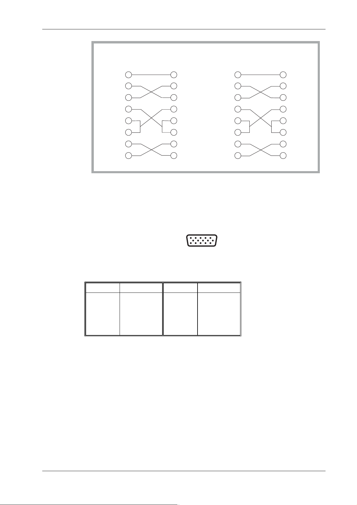
2965A/66A/67/68 RADIO TEST SET
Test Set Test Set
9-WAY 9-WAY
SG
RXD
TXD
DCD
DSR
RTS
CTS
External monitor port
This has a 15-way D-type socket which is mounted on the rear panel. See Fig. 2-6.
PC
PC
9-WAY 25-WAY
5
2
3
4
1
6
7
8
5
SG
2
RXD
3
TXD
4
DTRDTR
1
DCD
6
DSR
7
RTS
CTS
8
SG
RXD
TXD
DCD
DSR
RTS
CTS
5
2
3
4
1
6
7
8
7
SG
3
RXD
2
TXD
DTRDTR 20
8
DCD
6
DSR
4
RTS
5
CTS
C3619
Fig. 2-5 Null modem connections
5
15
1
610
C0791
11
Fig. 2-6 External monitor socket contacts (as seen facing panel)
The functions of the socket contacts are as follows:-
Contact Function Contact Function
1
2
3
4
5
6
7
Video red
Video green
Video blue
No connection
Ground (Red)
Ground (Green)
Ground (Blue)
9
10
11
12
13
14
15
NC
NC
No connection
No connection
HSYNC
VSYNC
No connection
46882/274 2-7
Page 59

INSTALLATION
Accessory port
This has a 25-way D-type plug which is mounted on the rear panel. See Fig. 2-7.
1
14
13
C0786
25
Fig. 2-7 Accessory port plug contacts (as seen facing panel)
Some of the accessories available for use with the Test Set use this port. Their use is described in
relevant documentation. The use of the Logic lines (pin connections 7, 8, 20, and 21) are
described in Chapter 3 under Logic lines within accessory connector.
The table below is included for information only. No inference is made as to the uses to which
this connector can be used for connecting any equipment other than approved devices
manufactured by IFR. The functions of the port contacts are as shown below.
Pin No. Function Remarks
1 No connection For future expansion. Do not use.
2 TETRA Base sync. input Used for TETRA Base Systems mode To
remain unconnected except as described in the
TETRA system supplement.
3 +12 V 100 mA max.
4 Ground (Logic) and
TETRA Base sync ground
5 Acc-SDA I2C data.
6 Status 2 Used by 2955 accessories.
7 Logic 3 See Note 1 below.
8 Logic 1 See Note 1 below.
9 Speaker
10 No connection
11 Ground (REV PWR) Used by directional power head.
12 Ground (FWD PWR) Used by directional power head.
13 No connection For future expansion. Do not use.
14 No connection For future expansion. Do not use.
15 No connection For future expansion. Do not use.
16
−12 V
17 Acc SCL I2C clock.
18 Status 3 Used by 2955 accessories.
19 Status 1 Used by 2955 accessories.
20 Logic 2 See Note 1 below.
21 Logic 0 See Note 1 below.
22 Ground (SPKR) Speaker ground.
23 REV PWR Used by directional power head.
24 FWD PWR Used by directional power head.
25 No connection For future expansion. Do not use
Note 1
Programmable in SYSTEMS mode.
Open drain drive pulled up to +5 V with 4K7 Ω. Max sink current, 10 mA for VOL = 1 V.
Use with power accessory lines.
Maximum load 8 Ω.
100 mA max.
2-8 46882/274
Page 60

Memory cards
Insert the Memory Card (Part no. 59000/189) in the slot and push it in to engage the connector.
Format each new Memory Card. For card set-up and operational information, see under Store and
recall facility in Chapter 3.
Rack mounting
Introduction
The test set can be mounted in a 19-inch rack using the Rack Mounting Kit (Part no. 54127/310),
which is available as an optional accessory. Fitting Instructions (publication no. 46882376)
accompany this kit.
The bracket height is 4U, 176 mm (7 in).
Routine safety testing and inspection
In the UK, the ‘Electricity at Work Regulations’ (1989) section 4(2) places a requirement on the
users of equipment to maintain it in a safe condition. The explanatory notes call for regular
inspections and tests together with a need to keep records.
The following electrical tests and inspection information is provided for guidance purposes and
involves the use of voltages and currents that can cause injury. It is important that these tests are
only performed by competent personnel.
Prior to carrying out any inspection and tests, the instruments must be disconnected from the
mains supply and all external signal connections removed. All tests should include the
instrument’s own supply lead, all covers must be fitted and the equipment supply switch must be
in the ‘ON’ position.
The recommended inspection and tests fall into three categories and should be carried out in the
following sequence:-
1. Visual inspection
2. Earth bonding tests
3. Insulation resistance test
2965A/66A/67/68 RADIO TEST SET
1. Visual inspection
A visual inspection should be carried out on a periodic basis. This interval is dependent on the
operating environment, maintenance and use, and should be assessed in accordance with
guidelines issued by the Health and Safety Executive (HSE). As a guide, this instrument when
used indoors in a relatively clean environment would be classified as ‘low risk’ equipment and
hence should be subject to safety inspections on an annual basis. If the use of the equipment is
contrary to the conditions specified, you should review the safety re-test interval.
As a guide, the visual inspection should include the following where appropriate:
Check that the equipment has been installed in accordance with the instructions provided (e.g. that
ventilation is adequate, supply isolators are accessible, supply wiring is adequate and properly
routed). Also check:-
• The condition of the mains supply lead and supply connector(s).
• The correct rating and type of supply fuses.
• Security and condition of covers and handles.
• Check the presence and condition of all warning labels and markings and supplied safety
information.
• Check the wiring in re-wireable plugs and appliance connectors.
• Check the cleanliness and conditio n of any ventilation fan filters.
• Check that the mains supply switch isolates the equipment from the supply.
• Check the supply indicator functions (if fitted).
If any defect is noted this should be rectified before proceeding with the following electrical tests.
46882/274 2-9
Page 61

INSTALLATION
2. Earth bonding tests
Earth bonding tests should be carried out using a 25 A (12 V maximum open circuit voltage) DC
source. Tests should be limited to a maximum duration of 5 seconds and have a pass limit of
0.1 Ω after allowing for the resistance of the supply lead. Exceeding the test duration can cause
damage to the equipment. The tests should be carried out between the supply earth and exposed
case metalwork, no attempt should be made to perform the tests on functional earths (e.g. signal
carrying connector shells or screen connections) as th is will result in damage to the equipment.
3. Insulation tests
A 500 V DC test should be applied between the protective earth connection and combined live and
neutral supply connections with the equipment supply switch in the ‘on’ position. It is advisable
to make the live/neutral link on the appliance tester or its connecto r to avoid the possibility of
returning the equipment to the user with the live and neutral poles linked with an ad-hoc strap.
The test voltage should be applied for 5 seconds before taking the measurement.
IFR Ltd employs reinforced insulation in the construction of its products and hence a minimum
pass limit of 7 MΩ should be achieved during this test.
Where a DC power adapter is provided with the equipment, the adapter must pass the 7 MΩ test
limit.
We do not recommend dielectric flash testing during routine safety tests. Most portable appliance
testers use AC for the dielectric strength test which can cause damage to the supply input filter
capacitors.
4. Rectification
It is recommended that the results of the above tests are recorded and checked during each repeat
test. Significant differences between the previous readings and measured values should be
investigated.
If any failure is detected during the above visual inspection or tests, the equipment should be
disabled and the fault should be rectified by an experienced Service Engineer who is familiar with
the hazards involved in carrying out such repairs.
Safety critical components should only be replaced with equivalent parts, using techniques and
procedures recommended by IFR Ltd.
The above information is provided for guidance only. IFR Ltd designs and constructs its products
in accordance with International Safety Standards such that in normal use they represent no hazard
to the operator. IFR Ltd reserves the right to amend the above information in the course of its
continuing commitment to product safety.
Cleaning
Before commencing any cleaning, switch off the equipment and disconnect it from the supply.
The exterior surface of the case may be cleaned using a soft cloth moistened in water. Do not use
aerosol or liquid solvent cleaners.
2-10 46882/274
Page 62

Contents
Introduction................................................................................................................................................3-5
Operating the instrument..............................................................................................................................3-5
Key groups............................................................................................................................................3-5
Soft key operation and display..............................................................................................................3-5
Modes and displays...................................................................................................................................... 3-6
Tx TEST mode......................................................................................................................................3-6
Rx TEST mode......................................................................................................................................3-8
DUPLEX TEST mode ..........................................................................................................................3-9
TONES mode......................................................................................................................................3-10
SYSTEMS mode.................................................................................................................................3-10
RF TEST mode ................................................................................................................................... 3-10
AF TEST mode................................................................................................................................... 3-11
Controls and connectors.............................................................................................................................3-12
Front panel..........................................................................................................................................3-12
Rear panel ...........................................................................................................................................3-17
Starting procedure......................................................................................................................................3-18
RF input/output level offsets...................................................................................................................... 3-18
RF generator output level modes ...............................................................................................................3-19
Standard output level mode.................................................................................................................3-19
Seamless output level mode................................................................................................................3-19
Inverse video indications............................................................................................................................3-19
Causes of dim inverse video displays ................................................................................................. 3-19
Logic lines within accessory connector......................................................................................................3-20
Transmitter testing...................................................................................................................................3-21
Transmitter testing - non-expanded............................................................................................................3-21
Transmitter testing - expanded...................................................................................................................3-26
Connections.........................................................................................................................................3-26
Oscilloscope........................................................................................................................................3-26
Spectrum analyzer...............................................................................................................................3-28
Modulation analyzer ...........................................................................................................................3-31
Off-air transmitter testing - non-expanded.................................................................................................3-33
Off-air transmitter testing - expanded........................................................................................................3-38
Connections.........................................................................................................................................3-38
Oscilloscope........................................................................................................................................3-38
Spectrum analyzer...............................................................................................................................3-38
Modulation analyzer ...........................................................................................................................3-39
Receiver testing.........................................................................................................................................3-40
Receiver testing - non-expanded................................................................................................................3-40
Receiver testing - expanded ....................................................................................................................... 3-44
Connections.........................................................................................................................................3-44
Oscilloscope........................................................................................................................................3-44
Audio analyzer....................................................................................................................................3-46
Duplex testing...........................................................................................................................................3-49
Full duplex testing......................................................................................................................................3-49
Duplex transmitter testing..........................................................................................................................3-53
Duplex transmitter testing - expanded........................................................................................................3-58
Connections.........................................................................................................................................3-58
Oscilloscope........................................................................................................................................3-58
Spectrum analyzer...............................................................................................................................3-58
Modulation analyzer ...........................................................................................................................3-59
Duplex receiver testing...............................................................................................................................3-59
Chapter 3
OPERATION
46882/274 3-1
Page 63

OPERATION
Duplex receiver testing - expanded............................................................................................................3-63
Connections.........................................................................................................................................3-63
Oscilloscope........................................................................................................................................3-63
Audio analyzer....................................................................................................................................3-64
RF testing..................................................................................................................................................3-65
RF input/output testing - non-expanded.....................................................................................................3-65
RF input/output testing - expanded ............................................................................................................3-70
Connections.........................................................................................................................................3-70
Oscilloscope........................................................................................................................................3-70
Spectrum analyzer...............................................................................................................................3-70
Modulation analyzer............................................................................................................................3-71
SSB transmitter testing - non-expanded.....................................................................................................3-71
SSB transmitter testing - expanded ............................................................................................................3-76
Connections.........................................................................................................................................3-76
Spectrum analyzer...............................................................................................................................3-76
Sideband analyzer ...............................................................................................................................3-79
CW analyzer........................................................................................................................................3-81
SSB receiver testing - non-expanded .........................................................................................................3-83
SSB receiver testing - expanded.................................................................................................................3-86
Connections.........................................................................................................................................3-86
Oscilloscope........................................................................................................................................3-86
Audio analyzer....................................................................................................................................3-87
Audio testing.............................................................................................................................................3-90
Audio input/output testing - non-expanded................................................................................................3-90
Audio input/output testing - expanded.......................................................................................................3-94
Connections.........................................................................................................................................3-94
Oscilloscope........................................................................................................................................3-94
Audio analyzer....................................................................................................................................3-95
Audio multimeter testing............................................................................................................................3-95
Signalling codes testing............................................................................................................................3-99
Sequential tones..........................................................................................................................................3-99
CTCSS......................................................................................................................................................3-106
DTMF (dual-tone multi-frequency) .........................................................................................................3-108
Introduction.......................................................................................................................................3-108
Connections.......................................................................................................................................3-109
Procedure ..........................................................................................................................................3-109
Display (GENERATE/DECODE) ....................................................................................................3-114
Display (GENERATE)......................................................................................................................3-115
Display (DECODE) ..........................................................................................................................3-115
DCS (digitally coded squelch) .................................................................................................................3-116
POCSAG pager........................................................................................................................................3-119
Systems testing........................................................................................................................................3-123
Help and setting up ................................................................................................................................3-124
Help on topics...........................................................................................................................................3-125
Setting up..................................................................................................................................................3-125
Test options.......................................................................................................................................3-131
Inputs and outputs.............................................................................................................................3-136
Miscellaneous configurations............................................................................................................3-137
Calibrations ..............................................................................................................................................3-140
Demonstrations.........................................................................................................................................3-142
Versions of software.................................................................................................................................3-142
Store and recall facility..........................................................................................................................3-143
Introduction..............................................................................................................................................3-143
Purpose of this section ......................................................................................................................3-143
Storing and recalling systems data....................................................................................................3-143
Accessing the Store and recall facility..............................................................................................3-143
3-2 46882/274
Page 64

2965A/66A/67/68 RADIO TEST SET
Formatting a memory card................................................................................................................3-143
Typical storage sizes.........................................................................................................................3-144
Storing instrument settings internally.......................................................................................................3-145
Storing to a memory card.........................................................................................................................3-145
Recall........................................................................................................................................................3-149
User options ............................................................................................................................................ 3-150
100 kHz audio or modulation generator...................................................................................................3-150
Versatile tracking generator.....................................................................................................................3-150
List of figures
Fig. 3-1 TRANSMITTER TEST displays..................................................................................................3-7
Fig. 3-2 RECEIVER TEST displays.......................................................................................................... 3-8
Fig. 3-3 DUPLEX TEST displays..............................................................................................................3-9
Fig. 3-4 Front panel.................................................................................................................................. 3-12
Fig. 3-5 Rear panel...................................................................................................................................3-17
Fig. 3-6 TRANSMITTER TEST display with bar charts.........................................................................3- 22
Fig. 3-7 TRANSMITTER TEST SCOPE expanded display with markers..............................................3-27
Fig. 3-8 TRANSMITTER TEST SPECTRUM ANALYZER expanded display with markers...............3-29
Fig. 3-9 TRANSMITTER TEST MOD ANALYZER expanded display with markers..........................3-32
Fig. 3-10 OFF-AIR TRANSMITTER TEST display with bar charts....................................................... 3-35
Fig. 3-11 RECEIVER TEST display with bar charts................................................................................3-41
Fig. 3-12 RECEIVER TEST SCOPE expanded display with markers..................................................... 3-45
Fig. 3-13 RECEIVER TEST AUDIO ANALYZER expanded display with markers..............................3-47
Fig. 3-14 DUPLEX TEST display with bar charts....................................................................................3-50
Fig. 3-15 DUPLEX TEST (Tx) display with bar charts............................................................................3-54
Fig. 3-16 DUPLEX TEST (Rx) display with bar charts ...........................................................................3-60
Fig. 3-17 RF INPUT/OUTPUT TEST display with bar charts.................................................................3-66
Fig. 3-18 SSB TRANSMITTER TEST display with bar charts ...............................................................3-72
Fig. 3-19 SSB TRANSMITTER TEST display with suppression analyzer..............................................3-74
Fig. 3-20 SSB TRANSMITTER TEST SPECTRUM ANALYZER expanded display ...........................3-78
Fig. 3-21 SSB Transmitter Lower Sideband Analyzer expanded display with markers...........................3-79
Fig. 3-22 SSB TRANSMITTER CARRIER WAVE ANALYZER expanded display.............................3-82
Fig. 3-23 SSB RECEIVER TEST display with bar charts........................................................................3-84
Fig. 3-24 SSB RECEIVER AUDIO ANALYZER expanded display with markers.................................3-88
Fig. 3-25 AUDIO INPUT / OUTPUT TEST display with bar charts.......................................................3-91
Fig. 3-26 AUDIO TEST MULTIMETER display....................................................................................3-96
Fig. 3-27 Connections for power consumption testing. ............................................................................3-97
Fig. 3-28 Tx TEST SEQUENTIAL TONES DECODE display.............................................................3-100
Fig. 3-29 Rx TEST SEQUENTIAL TONES GENERATE display........................................................ 3-102
Fig. 3-30 Rx TEST CTCSS GENERATE display..................................................................................3-107
Fig. 3-31 DTMF displays........................................................................................................................3-109
Fig. 3-32 Tx TEST DTMF GENERATE/DECODE display .................................................................. 3-110
Fig. 3-33 Tx TEST DTMF DECODE display ........................................................................................3-111
Fig. 3-34 Tx TEST DTMF GENERATE display....................................................................................3-112
Fig. 3-35 Rx TEST DTMF GENERATE display ................................................................................... 3-114
Fig. 3-36 Tx TEST DCS DECODE display............................................................................................ 3-116
Fig. 3-37 Rx TEST DCS GENERATE display.......................................................................................3-118
Fig. 3-38 Rx TEST POCSAG PAGER TEST display............................................................................3-121
Fig. 3-39 HELP AND SET-UP menu..................................................................................................... 3-124
Fig. 3-40 HELP AND SET-UP - top level.............................................................................................. 3-126
Fig. 3-41 HELP AND SET-UP - test options ......................................................................................... 3-127
Fig. 3-42 HELP AND SET-UP - test options, digital systems................................................................3-128
Fig. 3-43 HELP AND SET-UP - input/output........................................................................................3-129
Fig. 3-44 HELP AND SET-UP - miscellaneous instrument configurations...........................................3-130
Fig. 3-45 USER-NAME ENTRY menu..................................................................................................3-139
Fig. 3-46 Entering user names.................................................................................................................3-139
Fig. 3-47 Store and recall facility - block diagram..................................................................................3-144
Fig. 3-48 STORE FACILITY - SETTINGS menu .................................................................................3-145
46882/274 3-3
Page 65

OPERATION
Fig. 3-49 Entering an internal store name...............................................................................................3-147
Fig. 3-50 Entering a memory card store name........................................................................................3-148
Fig. 3-51 Memory card store locations 20 to 29 .....................................................................................3-148
Fig. 3-52 Normal, doubler and divider testing........................................................................................3-151
Fig. 3-53 Mixer testing............................................................................................................................3-152
3-4 46882/274
Page 66

2965A/66A/67/68 RADIO TEST SET
Introduction
With the exception of the section User options (page 3-150), this chapter refers to an instrument
with factory preset settings, prior to any customisation.
Operating the instrument
Key groups
The test set operation is controlled by six groups of keys:(1) Mode keys. These keys permit the selection of the type of testing or operation, and enable
appropriate adjustment/selection of test values (e.g. frequency, signal level, etc.).
(2) Function keys. These keys are the means of selecting the set-up functions appropriate to the
mode that has been selected, together with miscellaneous functions. In Rx TEST mode, for
example, pressing the [RF GEN] key followed by the [FREQ] key allows the RF generator
frequency to be set using the DATA keys.
(3) Data keys. These keys permit the setting of values and units appropriate to the mode and
function key previously pressed.
(4) Soft keys. These keys around the display are used for operations associated with the display
itself. A label for each key in use is shown on the display next to the key. Some soft keys
change the display, some provide control of a display feature, and some permit selection
from a list of options which are successively displayed as the soft key is successively
pressed.
(5) Input/output keys. These are the [RF SELECT] and the two [AC DC] keys. The
[RF SELECT] key permits the TNC and N type RF sockets to be selected for input or output
function. The two [AC DC] keys select the type of coupling associated with the EXT MOD
INPUT and AF INPUT BNC sockets.
(6) [INC] keys. These permit frequencies and levels to be incremented by amounts previously
set up according to the mode, function and display currently in use.
In addition to the keys provided for instrument control, there are three groups of rotary controls:(1) VARIABLE control. This permits frequencies, levels etc. to be set or adjusted.
(2) VOLUME and SQUELCH controls. These permit the volume and squelch level of the
internal speaker to be adjusted. The squelch control also affects some displays in permitting
a signal threshold to be adjusted.
(3) INTENSITY and SCOPE POSITION controls. These controls permit adjustment of display
brightness and vertical position respectively.
Soft key operation and display
Soft keys operate in one of three different ways:(1) ON off toggle. Pressing the soft key once switches the soft key’s function on, pressing it
again switches the soft key’s function off. The soft key’s legend indicates the current state
of the soft key’s function. Examples are the Tx TEST mode’s [Tx tune ON off], and
[gen 1 on OFF].
(2) Select from list. Successively pressing the soft key cycles and selects through a list of
options. An example is the Tx TEST mode’s [mod type] soft key, where selection is
indicated by the display showing AM DEPTH, ΦM DEVN and FM DEVN. A select from
list soft key may introduce additional soft keys to support its function; for example, the Tx
TEST mode’s [hold ranges] and [auto range] soft keys.
46882/274 3-5
Page 67

OPERATION
(3) Select display. These soft keys are in groups of mutually exclusive keys. On selection of
each of these grouped soft keys, the others are reset. After selection, a second key press
provides an alternative type of information presentation. These keys are labelled on the
display with the function/display that will be selected on the next k ey-press. Examples are
the Tx TEST mode’s [spec ana], [mod ana] and [scope] keys.
Modes and displays
This is a summary of the principal features and advantages of each of the many modes and
displays that are provided.
Tx TEST mode
In normal transmitter tests, the transmitter is connected directly to one of the RF input connectors.
In the off-air transmitter tests, the transmitter is connected to its antenna. On the test set, an
antenna is fitted to one of the RF input connectors.
Normal
See Fig. 3-1 on page 3-7. In this mode, the test set functions as a receiver which measures the
following:-
A transmitter’s frequency (or frequency offset) and power.
(a)
(b) The modulation type, frequency, deviation or depth and distortion and/or noise.
The test set automatically tunes to the transmitter’s frequency. Alternatively, the transmitter can
be tuned for minimum or zero offset by manually tuning the test set. The manually-entered
transmitter frequency can be increased or decreased by a previously entered increment.
The test set also provides an AF signal for modulating the transmitter. You can select any or all of
the three AF generators. Alternatively, the wide-range (1 Hz to 100 kHz) generator can be used
(see User options; 100 kHz audio or modulation generator on page 3-150). Each frequency and
level is set independently and each generator can be enabled or disabled. The audio frequencies
and levels can be increased or decreased by previously entered increm
The three AF generators can be configured with the three modulation generators to provide a
single LF source with a range of 1 Hz to 100 kHz. This single source can be used as a modulation
generator or as a wide-range LF generator.
There are seven different stages of display as follows:(a) Primary with bar charts - the fastest operational measurement mode
(b) Primary with oscilloscope
(c) Primary with spectrum analyzer
(d) Primary with modulation analyzer
(e) Expanded oscilloscope - the fastest mode of operation of the oscilloscope
(f) Expanded spectrum analyzer - the fastest mode of operation of the spectrum analyzer
(g) Expanded modulation analyzer - the fastest mode of operation of the FFT
ents.
Off-air
The test set functions as a receiver which measures the following:(a) A transmitter’s frequency offset and the power that is induced in the antenna
(b) The modulation type, frequency, deviation or depth and distortion and/or noise
The test set is manually tuned to the transmitter’s frequency. The transmitter can be tuned for
minimum or zero offset. The manually-entered transmitter frequency can be increased or
decreased by a previously-entered increment.
The test set provides an AF signal as for normal tests.
There are seven different stages of display as for normal tests.
3-6 46882/274
Page 68

2965A/66A/67/68 RADIO TEST SET
Fig. 3-1 TRANSMITTER TEST displays
Demodulation measurements
Demodulation measurements can be shown as either peak or RMS values. Switching from one to
the other is done via the SET-UP menu; see page 3-132 for further information. The measurement
e is displayed next to the value. The default is peak. Note that the RMS measurements are
typ
made with a different hardware configuration, not simply calculated from the peak levels.
46882/274 3-7
Page 69

OPERATION
Rx TEST mode
See Fig. 3-2.
In this mode, the test set functions as a transmitter which provides a modulated signal to a
receiver. There are three modulation generators and the option of using an external generator.
Each frequency and level is set independently and each generator can be enabled or disabled. The
RF frequency and level and modulation frequencies and deviations or depths can be increased or
decreased by previously entered increments.
The test set also measures the level, frequency and distortion and/or noise of the AF signal that has
been demodulated by the receiver.
There are five different stages of display as follows:(a) Primary with bar charts.
(b) Primary with oscilloscope.
(c) Primary with audio analyzer.
(d) Expanded oscilloscope.
(e) Expanded audio analyzer.
Fig. 3-2 RECEIVER TEST displays
3-8 46882/274
Page 70

2965A/66A/67/68 RADIO TEST SET
DUPLEX TEST mode
See Fig. 3-3.
In this mode, the test set functions simultaneously as a transmitter (to test a receiver as shown on
the left side of the display) and as a receiver (to test a transmitter as shown on the right side of the
display). Functioning is the same as in the Tx TEST and Rx TEST modes.
There are thirteen different stages of display as follows:(a) Primary display with bar charts.
(b) Seven DUPLEX TEST (Tx) displays. These are the same as the primary and expanded
displays in the Tx TEST mode.
(c) Five DUPLEX TEST (Rx) displays. These are the same as the primary and expanded
displays in the Rx TEST mode.
Fig. 3-3 DUPLEX TEST displays
46882/274 3-9
Page 71

OPERATION
TONES mode
SYSTEMS mode
In this mode, the test set receives or sends signalling codes as follows:(a) Sequential tones. CCIR, ZVEI, DZVEI, EIA, EEA and user-defined standards.
(b) DTMF (dual-tone multi-frequency) tones.
(c) DCS (digitally-coded squelch) signals.
(d) POCSAG radio pager signals.
(e) CTCSS tones.
To test a transmitter, the test set functions as a receiver by demodulating the transmitter’s RF
output signal and then decoding it. The decoded message is shown on the display.
To test a receiver, the test set functions as a signal generator which generates an encoded RF
signal.
In this mode, the test set functions as a Base Station for testing cellular or trunked portable
transceivers. (When TETRA BASE or TETRA DIRECT is selected the test set functions as a
mobile.) The following systems are available:-
a) NMT-450/900
b) MULTI-AMPS
c) MULTI-TACS
d) MPT1327
e) PMR
f) GSM 900 (2966A, 2967, 2968)
g) GSM 1800 (2967)
h) GSM 1900 (2967)
i) TETRA MOBILE (2968)
j) TETRA BASE (2968)
k) TETRA DIRECT (2968)
The operating instructions for each of these systems options is contained in the appropriate
Operating Manual Supplement. These are supplied with instruments fitted with cellular or
trunking system options. They are also supplied when the appropriate software is installed
following the supply of the test set.
The IFR part numbers of these manuals will be found in About this manual at the front of this
manual.
Selecting other operating modes
While the Systems mode is selected, if other operating modes such as DUPLEX TEST mode are
selected, the test set will transfer applicable settings to the new mode. This allows the equipment
under test to be examined using the selected mode, while continuing to operate as set in Systems
mode. The test set can be returned to Systems mode at any time.
RF TEST mode
This mode displays a soft key selected menu providing:(1) RF input/output test.
(2) SSB test.
RF input/output test
This mode is for testing a UUT such as a repeater without having extraneous details on the
display. It is the same as the DUPLEX TEST mode except as follows:-
(a) The AF settings and measurements are not included in the displays.
(b) The RF frequency and level, and modulation frequencies and deviations or depths, can be
increased or decreased by previously entered increments.
3-10 46882/274
Page 72

2965A/66A/67/68 RADIO TEST SET
SSB test
This optional mode is for testing Single Sideband (SSB) radios. The test set is configured as a
transmitter or receiver. In the SSB transmitter test mode, the transmitter is connected directly to
one of the RF input connectors. In this mode, the test set functions as a receiver which measures
the following:-
(a) A transmitter’s frequency (or frequency offset) and power.
(b) The modulation frequency and distortion.
The test set automatically tunes to the transmitter’s frequency. Alternatively, the transmitter can
be tuned for minimum or zero offset by manually tuning the test set. The manually-entered
transmitter frequency can be increased or decreased by a previously entered increment.
Two AF generators have independent frequency and level settings and are provided to modulate
the transmitter.
There are eight different stages of display, as follows:(a) Primary with bar charts.
(b) Primary with suppression analyzer.
(c) Primary with spectrum analyzer.
(d) Primary with sideband analyzer.
(e) Primary with carrier wave analyzer.
(f) Expanded spectrum analyzer.
(g) Expanded sideband analyzer.
(h) Expanded carrier wave analyzer.
In the SSB receiver mode, the test set functions as a transmitter which provides a modulated signal
to the radio receiver. The test set also measures the level, frequency and distortion of the AF
signal that has been demodulated by the receiver.
There are five different stages of display, as follows:(a) Primary with bar charts.
(b) Primary with oscilloscope.
(c) Primary with audio analyzer.
(d) Expanded oscilloscope.
(e) Expanded audio analyzer.
AF TEST mode
This mode displays a soft key selected menu providing:(1) Audio input/output test.
(2) A full function multimeter.
Audio input/output test
This mode is for testing an item of audio equipment (e.g. an amplifier or filter).
The test set provides an AF signal to the unit under test (UUT). You can select any or all of the
three AF generators. Alternatively, the wide-range (1 Hz to 100 kHz) generator can be used (see
User options; 100 kHz audio or modulation generator on page 3-150). Each frequency and level
is set independently and each generator can be enabled or disabled. The audio frequencies and
levels can be increased or decreased by previously entered increm
can be configured with the three modulation generators to provide a single LF source with a range
of 1 Hz to 100 kHz. The test set measures the level, frequency and distortion and/or noise of the
AF signal that is fed from the UUT.
46882/274 3-11
ents. The three AF generators
Page 73

OPERATION
Full function multimeter
This mode is for measuring AC and DC volts and amps, resistance, and continuity.
WARNING
Do not connect voltages in excess of 350 V AC or DC, or attempt to measure currents in
excess of 10 A.
Controls and connectors
Front panel
See Fig. 3-4 on page 3-12. The numerical references are used throughout this chapter.
1
SUPPLY
SQUELCHVOLUME
W
CAT II
CAT II
300V
300V
MAX
MAX
2
AV
10 A
MAX
311
--
10 15
radio test set
INTENSITYMULTIMETER
SCOPE
POSITION
ä
ä
ä
Tx
TEST
Rx
TEST
DUPLEX
TEST
TONES RECALL
SYSTEMS
RF
TEST
D
AF
TEST
HELP
SET-UP
AC
DC
EXT MOD
INPUT
16
-
23 24 25 26
FUNCTIONMODE
FREQ
Tx
REF
RF
GEN
Rx ms B
Rx=Tx
FREQ
MOD
GEN
AF
GEN
INC
FREQ
AC
INPUT
ä
LEVEL COPY
CHANNEL STORE
DEVN
DEPTH
d
DC
AF
INC
VARIABLE
AF GEN
OUTPUT
ä
DATA
8
7
4
1
0
9
5
6
3
2
.
-
E
#F
*
DELETE
ä
ä
!
RF
SELECT
ä
ä
ä
ä
MHz
s
kHz
Hz
ms
dB
W
dBm
ENTER
150W MAX
50W
1W MAX
C5866
V
A
mV
Vm
C
%
D
rad
27 28 29 30 31 32 33 34 35
363738394041
Fig. 3-4 Front panel
CRT screen and soft keys
(1) Screen. The display shows the functions of the soft keys, instrument settings, measurement
results, measurement bar charts and an oscilloscope or analyzer graticule and trace as
appropriate for the selected method of operation.
(2) Soft keys. These are the blank keys at each side and at the bottom of the screen. Their
functions are shown as appropriate on the screen. The current selection is shown in inverse
video.
Toggle action soft keys. In many cases, soft keys are used to toggle between ON and OFF
states. For example, when the RF generator is switched ON, the associated soft key is shown
as [RF gen ON off], where ON is highlighted. When the key is pressed, the RF generator is
switched OFF, and the soft key changes to [RF gen on OFF], where OFF is highlighted.
3-12 46882/274
Page 74

2965A/66A/67/68 RADIO TEST SET
Screen saver
The test set has a screen saver feature to prevent burn-in on the CRT. This can happen when the
instrument is left on for long periods of time, with an unchanging display.
The screen saver display replaces the current display after a preset time during which the front
panel controls have not been used and no remote control addressing has taken place.
You have control over the screen saver display pattern, the delay time and whether it is enabled or
not. The screen saver has two alternative displays, one called
These options are controlled from the SET-UP: SCREEN SAVER menu. Access to this menu is
via the key sequence [HELP SET-UP], [SET-UP], [MISC CONFIG], [screen saver]. The soft
keys on the left of the screen and their actions are:-
[saver delay] Repeatedly pressing this key sets the delay before th e screen saver is initiated.
The available delays are from 10 minutes to 60 minutes at 10 minute intervals. The disable
option is also included in the choices.
[screen saver] Toggles between the two display patterns.
[saver test] To test the operation of the screen saver. Pressing this key will start the screen
saver without waiting for the time delay to elapse.
While the screen saver is running, all measurements and tests are suspended. The screen saver is
cancelled by pressing any front panel key, rotating the VARIABLE control, removing or inserting
a memory card, or by the test set being addressed by the remote controller.
A key press that cancels the screen saver is not decoded as an action but all keys become active on
their specified functions thereafter.
Bouncing Balls, the other Polygons.
MODE keys (blue legends)
(3) [Tx TEST] key. To select the Tx TEST mode. The first time that this key is used after
switching on, the top level TRANSMITTER TEST display appears. After OFF-AIR and/or
expanded displays have been selected, the last one re-appears when this key is used again.
When one of these has appeared, the top level TRANSMITTER TEST display appears when
this key is pressed a second time.
(4) [Rx TEST] key. To select the Rx TEST mode. The first time that this key is used after
switching on, the top level RECEIVER TEST display appears. After expanded displays
have been selected, the last one re-appears when this key is used again. When one of these
has appeared, the top level RECEIVER TEST display appears when this key is pressed a
second time.
(5) [DUPLEX TEST] key. To select the DUPLEX TEST mode. The first time that this key is
used after switching on, the top level DUPLEX TEST display appears. After expanded
displays have been selected, the last one re-appears when this key is used again. When one
of these has appeared, the top level DUPLEX TEST display appears when this key is pressed
a second time.
(6) [TONES] key. To select signalling codes testing. The first time that this key is used after
switching on, a SEQUENTIAL TONES DECODE or GENERATE display appears,
depending on the previous mode. After other displays have been selected, the last one
re-appears when this key is used again.
(7) [SYSTEMS] key. To select system testing on a cellular or trunked mobile radio.
(8) [RF TEST] key. To select the RF TEST mode. The first time that this key is used after
switching on, the top level RF INPUT/OUTPUT TEST display appears. After expanded
displays have been selected, the last one re-appears when this key is used again. When one
of these has appeared, the top level RF INPUT/OUTPUT TEST display appears when this
key is pressed a second time.
46882/274 3-13
Page 75

OPERATION
FUNCTION keys (green legends)
(9) [AF TEST] key. To select the AF TEST mode. The first time that this key is used after
switching on, the top level AUDIO INPUT/OUTPUT TEST display appears. After
expanded displays have been selected, the last one re-appears when this key is used again.
When one of these has appeared, the top level AUDIO INPUT/OUTPUT TEST display
appears when this key is pressed a second time.
(10) [HELP SET-UP] key. To select the HELP AND SET-UP menu for access to pages of help
information or to the SET-UP menu.
(11) [Tx] (or [REF]) key. To select the transmitter for manual entering of its frequency by using
the DATA keys (24) and (26). Also, to set the transmitter frequency that is used as the REF
FREQ in the spectrum analyzer displays. When this key is used, Tx and FREQ appear on
the display in inverse video.
(12) [RF GEN] (or [Rx]) key. To select the internal RF generator prior to using the [FREQ] key
(16) and/or [LEVEL] key (17). When this key is used, GEN appears on the display in
inverse video.
(13) [Rx=Tx FREQ] key. To tune the RF generator to the frequency of the transmitter that is
connected to the RF N-type socket (35) or the RF TNC socket (36). Therefore, the receiver
section of a transceiver can be tested without having to enter the frequency. For use only in
the Tx TEST, DUPLEX TEST and RF INPUT/OUTPUT TEST modes with the transmitter
on and automatic tuning in operation.
(14) [MOD GEN] key. To select one of the three internal modulation generators (or the
wide-range modulation generator), prior to using the [FREQ] key (16) and/or
[DEVN DEPTH] key (19). When this key is used, MOD appears on the display in inverse
video.
(15) [AF GEN] key. To select one of the three internal AF generators (or the wide-range AF
generator), prior to using the [FREQ] key (16) and/or [LEVEL] key (17). When this key is
used, AF appears on the display in inverse video.
FUNCTION keys (brown legends)
(16) [FREQ] key. To precede the entry of a frequency on the DATA keys (24). After the
numerical entry, a unit key (26) is used. When reverting to a mode after setting the
frequency in another mode, the frequency is as previously set in the current mode or as reset
in the other mode according to the selection on the HELP AND SET-UP menu. When this
key is used, FREQ appears on the display in inverse video.
(17) [LEVEL] key. To precede the entry of an RF level or AF level on the DATA keys (24).
After the numerical entry, a unit key (26) is used. When reverting to a mode after setting the
level in another mode, the level is as previously set in the current mode or as reset in the
other mode according to the selection on the HELP AND SET-UP menu. For the
modulation generators, this key can be used instead of the [DEVN DEPTH] key (19). When
this key is used, LEVEL appears on the display in inverse video.
(18) [CHANNEL] key. To precede the entry of a channel number on the DATA keys (24) and
the [ENTER] key (26). Provided that the channel numbers and increments have been
entered on the HELP AND SET-UP menu, this key can be used for tuning instead of the
[FREQ] key (16). CHAN and the channel number or FREQ and the frequency appear
according to the setting on the HELP AND SET-UP menu.
(19) [DEVN DEPTH] key. To precede the entry of an FM deviation, AM depth or ΦΜ deviation
on the DATA keys (24). After the numerical entry, a unit key (26) is used. The [LEVEL]
key (17) can be used instead. When this key is used, DEVN or DEPTH appears on the
display in inverse video.
(20) [INC] key. To precede the entry of an increment (of frequency, RF level, AF level, FM
deviation, AM depth or ΦM deviation) on the DATA keys (24). When this key is used, INC
appears on the display in inverse video. After the numerical entry, a unit key (26) is used.
Δ (for frequency) and δ (for other parameters) appear alongside the active
increments so that using one of the [×] or [Ø] keys (32) increases or decreases the
3-14 46882/274
Page 76

2965A/66A/67/68 RADIO TEST SET
appropriate settings. Only a single frequency increment and only a single level or deviation
or depth increment can be active. Entering a second increment disables the previous
increment. On the RECEIVER TEST and DUPLEX TEST (Rx) displays only, when a
second increment has been entered and then the first is reselected, its increment re-appears.
To activate this increment without changing its value, press the [ENTER] or any unit key
(26).
(21) [COPY] key. To hold the screen or enable the screen to be printed to a printer. Pressing
[DELETE] will clear the message window and any other key will re-enable display updates,
cancelling the screen hold facility. Pressing [COPY] twice will print the screen in
accordance with the parameters set with the key sequence [HELP SET-UP], [SET-UP],
[INPUT OUTPUT], [printer options].
Notes:
Make sure that the instrument is switched on before
otherwise the instrument may malfunction.
The printing of traces within the graticule area is quicker if you select single sweep (press
[single] key) or press [HELP SET-UP] (preventing further measurements) after the
message disappears.
(22) [STORE] key. To store the instrument’s front panel settings. See under Store and recall
facility on page 3-143.
[RECALL] key. To recall the settings that have been stored. See under Store and recall
(23)
facility on page 3-143.
turning on an attached printer,
DATA keys (grey legends)
(24) Numerical keys. For entering numerical data. Two of the keys are for a decimal point (.)
and a minus sign (−). These are also used for hexadecimal E and F and also for an asterisk
(*) and a hash sign (#). For hexadecimal A, B, C and D, the four upper unit keys (26) are
used.
(25) [DELETE] key. For deleting the previous number or sign.
DATA keys (brown legends)
(26) Unit keys. For entering the units of frequency (MHz, kHz and Hz) or voltage (V, mV
and μV) and relative level (dB and dBm) or modulation depth percentage (%) or modulation
angle (rad). They are also used for times (s, ms, and μs) and power (W). The four upper
keys are also used as numerical keys for hexadecimal A, B, C, and D. The bottom key is
also used as the [ENTER] key for numerical entries.
Miscellaneous controls (grey legends)
(27) VOLUME control. Adjusts the level of the loudspeaker that is used for monitoring.
(28) SQUELCH control. When this is fully anti-clockwise, the modulation meter outputs
(loudspeaker, oscilloscope trace, MOD FREQ reading, MOD deviation or depth reading, and
DEMOD output signal) are enabled. Turn this control clockwise to increase the carrier
threshold below which the modulation meter outputs are disabled. Instead of
SQUELCHED appears in inverse video.
(29) INTENSITY control. Adjusts the brightness of the display. Note that this control has little
or no effect on later instruments fitted with a colour LCD.
(30) SCOPE POSITION control. Adjusts the vertical position of the oscilloscope/analyzer trace.
(31) [AC DC] keys. To set AC or DC coupling at the AF INPUT socket (38) and EXT MOD
INPUT socket (39).
MOD FREQ,
(32) [×] and [Ø] keys. To increase or decrease the settings by the increments that have been
entered using the [INC] key (20). Δ (for frequency) and δ (for other parameters) appear
alongside the appropriate settings.
(33) VARIABLE control. Analogue control for adjusting the value of the parameter that is
shown in inverse video. The rate of change depends on the range.
46882/274 3-15
Page 77

OPERATION
Connectors and indicators
(34) [RF SELECT] key. For selecting the RF output and/or input to the RF N-type connector
(35) and the RF TNC connector (36). The signal paths are shown by the indicators.
(35) RF N-type output and input connector and indicators. The N-type socket is for output to a
receiver and/or input from a transmitter as set by the [RF SELECT] key (34). See under
Signal generator, RF frequency meter and RF power meter in Chap. 1. The connected signal
paths are shown by the indicators.
Note: For information about the RF generator output, see the sections RF input/output level
offsets on page 3-18 and RF generator output level modes on page 3-19.
WARNING
Hot surface
Input overload
(36) RF TNC output and input connector and indicators. TNC socket for output to a receiver
(37) AF GEN OUTPUT connector. BNC socket for one, two or three AF generator outputs in the
(38) AF INPUT connector. BNC socket for an audio signal. AC or DC coupling as set by the
(39) EXT MOD INPUT connector. BNC socket for externally generated modulation signals. See
Take care when touching the RF N-type connector after continuous power input.
If 50 W is exceeded, the temperature of the connector becomes excessive.
On the RF N-type connector, the input power should not exceed 150 W.
On the RF TNC connector, the input power should not exceed 1 W.
and/or input from a transmitter as set by the [RF SELECT] key (34). See under Signal
generator, RF frequency meter, and RF power meter in Chapter 1. The connected signal
paths are shown by the indicators.
range 1 Hz to 20 kHz, or, for the wide-range AF generator, 1 Hz to 100 kHz. See under
Audio generators in Chapter 1. AC or DC coupling is set by the [AC DC] key (31). The
connected signal path is shown by the indicator.
[AC DC] key (31). The connected signal path is shown by the indicator.
under Performance data; RF signal generator in Chapter 1. The connected signal path is
shown by the indicator.
(40) Memory card slot. To store set-ups and sequences of operations (see page 3-
emory card (Part no. 59000/189) is available as an optional accessory.
A m
(41) MULTIMETER terminals. Black, red and white posts for 4 mm plugs.
Red (+) and Black (−) for voltage and resistance measurements.
Red (+) and White (−) for current measurements.
Red, White and Black for power consumption measurements.
The use of the MULTIMETER facility is explained later, starting on page 3-95.
143).
Voltage and current ratings
On the MULTIMETER black, red and white terminals, the voltage with respect to
ground should not exceed ±300 V. At the red and white terminals, the input current
should not exceed 10 A.
3-16 46882/274
Page 78

2965A/66A/67/68 RADIO TEST SET
Rear panel
See Fig. 3-5 on page 3-17. The numerical references are used throughout this chapter.
50 49 48
GPIB
POWER SUPPLY
100/240 V
50/60 Hz
260 W MAX
N109
EXTERNAL
IEEE 488.1/488.2
MONITOR
OPTIONS
51
47 46 45 44 43 42
DEMODAFSERIAL EXT REFACCESSORY
PARALLEL
C5867
(42) PARALLEL connector. 25-way D-type socket. For connection to a Centronics or parallel
type printer or for automatic control of mobile interfaces. Make sure that the instrument is
switched on before
(43) 2965A only: IF connector. SMA socket. The signal from a transmitter under test is
available on this connector at 10.7 MHz.
2966A, 2968: EXT SIG GEN connector. SMA socket. Reserved for future use. May be
absent on some instruments.
(44) DEMOD connector. BNC socket. To output the demodulated signal that is being measured.
(45) AF connector. BNC socket. To output the AF signal that is being measured. The output
levels at the DEMOD and AF outputs are on fixed ranges only if the respective oscilloscope
or FFT mode is selected. When bar charts are displayed, the output levels are always
auto-ranging.
(46) EXT REF connector. BNC socket. To input an external reference signal or output an
internal reference signal according to the set-up. See under Miscellaneous configurations on
page 3-137.
Input/output conflict
Change the set-up to the external reference before connecting the external equipment.
Otherwise, damage could occur.
Fig. 3-5 Rear panel
turning on an attached printer, otherwise the instrument may malfunction.
46882/274 3-17
Page 79

OPERATION
(47) SERIAL connector. 9-way D-type male socket (DTE). For remote control of the test set
from a terminal or computer using the EIA/TIA-232-C (RS-232) interface. Can also be used
for the connection of a printer with a suitable cable. Make sure that the instrument is
switched on before
(48) ACCESSORY connector. 25-way D-type plug. For external accessories and for the control
of users equitpment. See Logic lines within accessory connector on page 3-20.
GPIB connector. 24-way IEEE 488.1 socket. For remote control of the test set using the
(49)
GPIB and a GPIB controller.
(50) POWER SUPPLY switch and AC input connector (3-way IEC plug). The power supply
adjusts automatically to AC supply voltages within the range 100 V to 240 V~, 50 to 60 Hz.
(51) EXTERNAL MONITOR connector. 15-way D-type socket. For VGA monitor unit to
duplicate the display on the test set but show it in colour.
Starting procedure
When the instrument has been installed in accordance with Chapter 2, depress the POWER
SUPPLY switch (50) to the ON position. After some self testing, one of the following displays
appears:-
(a) The factory default display (DUPLEX TEST).
(b) The default display that has been saved on the SET-UP : DEFAULT VALUES menu.
For further details on the power-on settings and display, see under [default values] on page 3-138.
The next
these, see under Modes and displays, page 3-6.
For connect
UUT - transmitter, receiver, RF unit, AF unit, etc.
steps are dependent on the mode and display that are required. For an introduction to
ions and further procedures, refer to the appropriate section for testing the particular
turning on an attached printer, otherwise the instrument may malfunction.
RF input/output level offsets
The indicated value of RF generator output level and RF input level can be offset so that these
values relate to the levels at the remote connector of an external attenuato r.
When an offset is effective on the indicated RF generator output level, an asterisk (*) is shown in
inverse video to the right of the level on the display.
Similarly, when an offset is effective on the indicated power input level, an asterisk (*) is shown
in inverse video to the right of the measured power level on the display.
The level of offset is entered from SET-UP OPTIONS: RF PORT I/O SET-UP. This is reached
through the key sequence, [HELP SET-UP], [SET-UP], [TEST OPTIONS], [rf port setup].
Pressing the [set offset] (RF gen level offset) key allows a positive or negative dB value to be
entered, within the range ±40.0 dB, with 1 decimal place resolution.
Pressing the [set offset] (receiver level offset) key allows a positive or negative dB value to be
entered, within the range ±40.00 dB, with 2 decimal place resolution. Any active offsets are
effective on the N type RF connector and the TNC RF connector.
Any RF generator level offset that is set on the SET-UP OPTIONS: RF PORT I/O SET-UP
menu will be taken into account by automatic test programs in SYSTEMS mode. If the
resulting change in RF GEN Level would take it beyond the test set’s range, the test
program will not attempt to do this. The result is that the default level of −80 dBm will be
used, possibly leading to the failure of the test.
The message
FAIL RFGEN LEVEL OUT OF RANGE will be displayed.
3-18 46882/274
Page 80

2965A/66A/67/68 RADIO TEST SET
RF generator output level modes
The RF generator has two output level modes; these are standard and seamless.
Standard output level mode
In the standard (default) mode, changes to the RF generator output level are made by a
combination of variable attenuators and switched attenuators, with switching occurring at
approximately 10 dB intervals throughout the range. This can cause comparatively large transient
level changes for small changes in output level setting.
Seamless output level mode
In the seamless mode the RF generator output level attenuators can be set to provide a range of
adjustment free from switched attenuator action. You set the upper limit of the range, and from
that point, smooth (seamless) adjustments can be made to reduce the output level by at least 20 dB.
The exact range will depend on the upper limit set and can approach 30 dB.
As you reduce the output level through the lower limit of the seamless range, the switched
attenuators operate as in the standard output level mode.
You change the mode and the upper limit, via the SET-UP menu; refer to page 3-126.
The upper l
imit can set to any value between -200 dBm and +50 dBm. The default is -80 dBm.
Inverse video indications
In some cases, the display of a measurement result may appear in dim inverse video. The general
reason for this is that the measurement hardware is not optimally ranged for the measurement, or
the measurement may be invalid due to the measurement setup.
Causes of dim inverse video displays
The three principal causes of dim inverse video displays are:Over-ranged readings
Instrument function dependency
Off-tune for SSB suppression measurement
Details of these are given below.
Over-ranged readings
The most likely cause of a dim inverse video indication is that the measurement is over-ranged,
that is, the quantity being measured is greater than that which can b e measured on the maximum
range.
Instrument function dependency
In some cases, ranging hardware may be shared between different functions. For example, if
measurement X and measurement Y use the same ranging hardware, but measurement Y controls
the ranging hardware, then measurement X may find that it is not optimally ranged for the level of
the quantity it is measuring. The result of measurement X is therefore displayed in inverse video.
The following combinations of functions may occasionally produce this situation:-
Controlling function Slaved function (may use inverse video)
Audio analyzer/scope Audio noise measurements
Audio analyzer/scope AF level measurements
Audio noise measurements AF level measurements
Demod analyzer/scope Demod noise measurements
Demod analyzer/scope Demod level measurements
Demod noise measurements Demod level measurements
Spectrum analyzer reference level Narrowband power measurement
46882/274 3-19
Page 81

OPERATION
Off-tune for SSB suppression measurement
When SSB suppression is measured with the test set receiver manually tuned, if the measured Tx
offset exceeds 30 Hz, the suppression measurement is still operating to specification, but the
results are displayed in inverse video to indicate that the measurements may have been
compromised by incorrect tuning.
Logic lines within accessory connector
Pin connections 7, 8, 20, and 21 of the Accessory Connector are designated as Logic 3, Logic 1,
Logic 2 and Logic 0 respectively. These connections pr ovide a capability to control external
equipment from the Test Set. The electrical conditions relating to these are:-
Open drain drive pulled up to +5 V with 4K7 Ω. Max sink current, 10 mA for VOL = 1 V.
The logic lines can be controlled either by remote control or by commands included in Systems
Autotest programs. Typical applications are the activation of Press To Talk (PTT) buttons on
PMR radios or Clear Down buttons on mobiles during automatic testing.
Remote control
The remote command :ACCESSORIES:LOGICn will control the state of the specified logic
line. See Chapter 5 of the Programming Manual for 2965A, 2966A, 2967 and 2968, part number
46882/280. The logic lines can also be controlled by the Systems sub-commands :ACCPORT
and :USEACCPORT. These are used as part of a command string such as
:PARAM:DTMFDECODE:ACCPORT or :PARAM:PAGEMOBILE:ACCPORT and
:PARAM:DTMFDECODE:USEACCPORT or :PARAM:PAGEMOBILE:USEACCPORT.
Specific commands may only be applicable to particular test systems. See Chapter 6 of the
Programming Manual referred to above.
Program control
The MIBASIC command ACCESSORY is used to control the logic lines in MIBASIC programs.
The MIBASIC autotest programs for Systems Testing can also utilise the logic lines through
commands such as TEST DTMFDECODE ACCPORT or TEST PAGEMOBILE ACCPORT
and TEST DTMFDECODE USEACCPORT or TEST PAGEMOBILE USEACCPORT.
Specific commands may only be applicable to particular test systems. See Chapters 2 and 3 of the
Programming Manual referred to above.
3-20 46882/274
Page 82

2965A/66A/67/68 RADIO TEST SET
Transmitter testing
Transmitter testing - non-expanded
Connections
Connect the transmitter’s RF output connector to the RF N-type socket (35) (or RF TNC socket
(36) if preferred for <1 W). Use the [RF SELECT] key (34) to select the appropriate connector,
indicated by the lit indicator.
If required, connect the transmitter’s AF input connector to the AF GEN OUTPUT socket (37).
WARNING
Hot surface
Input overload
Take care when touching the RF N-type connector after continuous power input. If 50 W is
exceeded, the temperature of the connector becomes excessive.
On the RF N-type connector, the input power should not exceed 150 W.
On the RF TNC connector, the input power should not exceed 1 W.
Procedure
Press the [Tx TEST] key (3). One of the TRANSMITTER TEST or OFF-AIR TRANSMITTER
TEST displays appears (whichever was last selected). If an OFF-AIR display is shown, press the
[normal Tx test] soft key. If an expanded display has appeared, press the [Tx TEST] key again.
The TRANSMITTER TEST display appears. See Fig. 3-6 on page 3-22.
In i
component at the RF N-type socket (provided it is > +10 dBm) or TNC socket (provided it is
> −10 dBm). Alternatively, the test set can be manually tuned. The set frequency is shown
against the
shown against the OFFSET legend.
Enter the required selections and settings on the display as follows:(a) To manually set the test set to the transmitter frequency, press the [Tx] key (11), and then
(b) Enter the type of modulation by using the [mod type] soft key. Pressing this key cycles
(c) To select an AF generator, press the [AF GEN] key (15). On the display, AF1, AF2 or AF3
ts factory default condition, the test set tunes automatically to the strongest frequency
Tx FREQ legend, and any offset between this and the measured incoming RF signal is
either enter the frequency by using the DATA keys (24) and (26), or use the VARIABLE
control (33) to adjust the frequency setting.
through all modulation types, as indicated by the display showing AM DEPTH, ΦM DEVN
and FM DEVN.
in inverse video shows which of the generators has been selected. To select another
generator, press the [1], [2] or [3] key (24) or press the [display gen] key repeatedly. (If the
wide-range AF generator has been enabled, AF4 will be shown in inverse video. See User
options; 100 kHz audio or modulation generator on page 3-150.) Enter the frequency and
evel by using the [FREQ] key (16), the [LEVEL] key (17) and the DATA keys (24) and
l
(26). Alternatively, adjust the frequency and level by using the VARIABLE control (33).
The output from AF generator 2 is sequential tones when this has been selected on the
TONES menu see under Signalling codes testing on page 3-99. To enable or disable each
AF generat
[gen 3 on OFF] keys. [tones on OFF] is shown instead of [gen 2 on OFF] when sequential
tones has been selected on the TONES menu.
or, press the appropriate [gen 1 on OFF], [gen 2 on OFF] (or [tones on OFF]) or
46882/274 3-21
Page 83

OPERATION
(d) To enter an increment for Tx frequency or AF frequency, press the [Tx] key (11) or
[AF GEN] key (15), the [FREQ] key (16) and then the [INC] key (20). Enter the increment
by using the DATA keys (24) and (26). Δ appears alongside the active increment. To
increase or decrease the frequency setting, press the appropriate [×] or [Ø] key (32). Only a
single frequency increment can be active. Entering one for Tx disables one for AF and vice
versa.
Fig. 3-6 TRANSMITTER TEST display with bar charts
(e) To enter an increment for AF level, press the [AF GEN] key (15), the [LEVEL] key (17) and
then the [INC] key (20). Enter the increment by using the DATA keys (24) and (26).
δ appears alongside the active increment. To increase or decrease the level setting, press the
appropriate [×] or [Ø] key (32).
(f) To select distortion or signal-to-noise measurement, use the [Tx dist S/N] soft key.
Transmitter distortion and signal-to-noise ratio are measured within the bandw idth of the
display’s FILTER value as set by the [band pass] or [low pass] soft key.
The distortion of the demodulated transmitter is measured at a modulating frequency that is
factory preset to 1 kHz. The distortion measurement frequency can be reset using the HELP
AND SET-UP mode to either a user-defined frequency or to the frequency of AF GEN 1.
Distortion, SINAD or S/N tests cannot be carried out while AF GEN 4 or MOD GEN 4 is
enabled.
To change the frequency of measurement, use the key sequence [HELP SET-UP],
[SET-UP], [TEST OPTIONS], [sinad & distn]. For further information, refer to the section
Help and setting up, page 3-132.
) To select filters, use the [IF BW], [band pass] or [low pass] soft key.
(g
Read off the measurements that are shown on the display in numerical form and as bar charts
(using the [bar charts] soft key), oscilloscope display (using the [scope] soft key), spectrum
analyzer display (using the [spec ana] soft key) or modulation analyzer display (using the
[mod ana] soft key).
3-22 46882/274
Page 84

2965A/66A/67/68 RADIO TEST SET
For the oscilloscope, spectrum analyzer and modulation analyzer displays, set parameters by using
the soft keys as below.
For the spectrum analyzer display, set the reference frequency. Use the [REF] key (11) and then
enter the frequency.
When the test set tunes automatically, it also selects the optimum spectrum analyzer reference
level and, as a result, also selects the input attenuator. This sets the level to the modulation
analyzer and to the selective power meter. With manual tuning at low levels, it is necessary to set
the spectrum analyzer reference level manually to achieve optimum accuracy. On the
TRANSMITTER TEST SPECTRUM ANALYZER display, set the REF LEVEL so that the signal
peak is within the top two graticule divisions.
Display
The following settings and measurements are shown:(a) Tx FREQ and INC. The frequency measurement of the transmitter’s output through the
RF N-type socket (35) (or RF TNC socket (36) if preferred for <1 W) or the tran smitter
frequency that has been entered manually and any increment. Δ appears alongside when the
increment is active.
(b) OFFST. The difference between the frequency measurement of the transmitter’s output and
the transmitter frequency that has been entered manually.
(c) POWER. The power measurement of the transmitter’s output. According to what has been
selected by using the [power BW] soft key, BROADBAND is shown, or IN BAND is shown
in inverse video.
(d) IF BW. The bandwidth for the transmitter IN BAND power measurement as selected by
using the [IF BW] soft key.
(e) MOD FREQ, and FM DEVN, AM DEPTH or ΦΜ DEVN. The modulation frequency and
deviation or depth measurements of the transmitter’s output.
(f) DISTN or S/N. When one of these is enabled, the distortion or signal-to-noise measurement
of the demodulated signal from the transmitter’s output.
(g) FILTER. The filter for the demodulated signal from the transmitter’s output as selected by
using the [band pass] or [low pass] soft key.
(h) AF1, AF2, AF3 or AF4 FREQUENCY, INC, LEVEL and INC. The settings on one of the
AF generators as selected by using the [1], [2] or [3] key (24) after the [AF GEN] key (15) or
using the [display gen] soft key. If the wide-range AF generator is enabled, the parameters
of this are shown. AF2 is not shown when sequential tones has been selected on the TONES
menu. When AF1, AF2, AF3 or AF4 is shown in inverse video, the [FREQ] key (16) or the
[LEVEL] key (17) can then be used. Δ (for frequency) and δ (for level) appear alongside
when the increments are active.
In particular circumstances, the test result may be shown in dim inverse video; refer to the
section Inverse video indications on page 3-
Bar charts
hen the [bar charts] soft key is used, the following measurements are shown:-
W
(a) POWER, BROADBAND or IN BAND. The measurement of the transmitter’s output
through the RF N-type socket (35) (or RF TNC socket (36) if preferred for <1 W).
(b) FM DEVN, AM DEPTH or ΦΜ DEVN. The modulation deviation or depth measurement of
the transmitter’s output.
(c) DISTN or S/N. When one of these is enabled, the distortion or signal-to-noise measurement
of the demodulated signal from the transmitter’s output.
The bar charts are auto-ranging except when the [hold ranges] soft key is used. The range
designators are then shown in inverse video.
19 for further information.
46882/274 3-23
Page 85

OPERATION
Maximum hold
Modulation level
Oscilloscope
The soft keys beneath the bar charts allow each measurement presentation to indicate actual levels
or maximum levels.
With [max hold ON] selected, the bar chart, and the digital readouts of it, will track any rise in the
measured level but will not track downward movement. Pressing the [reset] key will cause the
current level to be displayed before reapplying the maximum hold function. An
H is displayed at
the lower right of bar charts that are in the 'Maximum Hold' mode.
With [max hold OFF] selected, the bar chart and the associated digital readouts, will track any
change in the measured level.
The modulation level bar chart is a dual display, showing the positive modulation level on the
right and negative modulation level on the left. A digital reading of the indicated level is shown to
the side of each bar chart.
The digital reading of modulation level, shown in the top half of the display as
AM DEPTH or ΦM DEVN, is the average of the positive and negative readings.
FM DEVN,
When the [scope] soft key is used, the graticule and trace show the levels of the demodulated
signal from the transmitter’s output through the RF N-type socket (35) (or RF TNC socket (36) if
preferred for <1 W). Dotted horizontal lines on the graticule correspond to the 63% (average)
levels of full-scale.
Spectrum analyzer
When the [spec ana] soft key is used, the graticule and trace show the spectrum of the
transmitter’s output through the RF N-type socket (35) (or RF TNC socket (36) if preferred for
<1 W).
At the bottom of the display, the REF FREQ setting is shown, which corresponds to the central
vertical dotted line on the graticule.
Modulation analyzer
When the [mod ana] soft key is used, the graticule and trace show the spectrum of the
demodulated signal from the transmitter’s output through the RF N-type socket (35) (or RF TNC
socket (36) if preferred for <1 W).
At the bottom of the display, the REF FREQ setting is shown, which corresponds to the central
vertical dotted line on the graticule. In particular circumstances, the test result may be shown in
inverse video; refer to the section Inverse video indications on page 3-19 for further information.
Soft key
s at left side of screen
The following keys are shown at the left side of the screen, (unless the wide-range AF
generator/modulation generator has been enabled):-
(a) [Tx tune ON off] key. To disable automatic tuning or to return to automatic tuning after a
transmitter frequency has been set manually.
(b) [mod type] key. To select the type of modulation of the transmitter’s output. The options
are FM DEVN, AM DEPTH and ΦM DEVN.
(c) [display gen] key. To select the AF generator before or after using the [AF GEN] key (15).
Press the key repeatedly to step through 1,2 and 3. AF2 is not available when sequential
tones has been selected on the TONES menu. The frequency and level are shown for the
selected generator. When the [AF GEN] key is used, AF1, AF2, or AF3 appear in inverse
video. The [FREQ] key (16) or the [LEVEL] key (17) can then be used.
(d) [gen 1 on OFF], [gen 2 on OFF] (or [tones on OFF]) and [gen 3 on OFF] keys. To enable
or disable the AF generators. [tones on OFF] is shown instead of [gen 2 on OFF] when
sequential tones has been selected on the tones menu.
3-24 46882/274
Page 86

2965A/66A/67/68 RADIO TEST SET
(e) [off-air test] key. To select the OFF-AIR TRANSMITTER TEST display.
(f) [hold ranges], [auto range], [expand ON off], (or [expand on OFF]).
When bar charts are displayed, they can be auto-ranging or manually selected. When this key is
labelled [hold ranges], pressing it will disable the auto-ranging function and cause the keys
beneath the bar charts to become [range up] and [range down] keys.
When it is labelled [auto range], pressing it will enable the auto-ran ging function to the bar charts.
When the spectrum analyzer, modulation analyzer, or oscilloscope function is active, this key
becomes [expand ON off] or [expand on OFF] and will toggle between the expanded and normal
mode of each.
When the wide-range AF generator/modulation generator has been selected, only the following
soft keys are shown at the left side of the screen:-
(a) [Tx tune ON off] key. As above.
(b) [mod type] key. As above.
(c) [afgens 1 to 3] key. Pressing this key will cause the message
again to continue. Press any other key to cancel.
to be displayed.
If the key is pressed again, the wide-range AF generator/modulation generator will be
disabled and AF generators 1 to 3, and modulation generators 1 to 3, will be enabled. The
wide-range AF generator/modulation generator can only be enabled again through the HELP
AND SET-UP menus.
(d) [gen 4 ON off] key. Repeatedly pressing this k ey will alternately turn the wide-range AF
generator on and off. If the wide-range MODULATION generator is in the ON condition,
pressing this key will turn it off, and turn the wide-range AF generator on. But pressing this
key to turn the wide-range AF generator off will not turn the wide-range modulation
generator on.
(e) [off-air test] key. As above.
(f) [hold ranges], [auto range], [expand ON off] (or [expand on OFF]) key. As above.
ARE YOU SURE? Press key
Soft keys at right side of screen
The following keys are shown at the right side of the screen:(a) [power BW] key. To select the bandwidth for transmitter power measurements. The options
are BROADBAND and IN BAND (shown in inverse video). BROADBAND means power
within the total bandwidth of the instrument. IN BAND means power at the displayed
frequency within the bandwidth that has been selected by using the [IF BW] soft key.
(b) [IF BW] key. To select the band width for transmitter power measurements. Values of
300 Hz, 1 kHz, 3 kHz, 10 kHz, 30 kHz, 110 kHz, 280 kHz and 3 MHz are available. Press
the soft key repeatedly until the required value is shown on the display.
(c) [band pass] key. This key selects a band-pass filter for inclusion in the AF path from the
demodulated output of the transmitter under test to the measuring circuits of the test set.
Selecting a band-pass filter will replace a previously selected low-pass filter. Repeatedly
pressing this key will select either the 0.3 to 3.4 kHz band-pass filter or a psophometric
weighting filter. When a weighting filter is selected, this is shown in inverse video on the
display.
When distortion or SINAD testing is selected, the 0.3 to 3.4 kHz filter is automatically
selected.
The choice of CCITT or CMESS psophometric weighting filter is set by using the key
sequence [HELP SET-UP], [SET-UP], [TEST OPTIONS], [filter options], [psoph filter].
See under Test options on page 3-
131.
46882/274 3-25
Page 87

OPERATION
Soft keys at bottom of screen
(d) [low pass] key. This key selects a low-pass filter for inclusion in the AF path from the
demodulated output of the transmitter under test to the measuring circuits of the test set.
Selecting a low-pass filter will replace a previously selected band-pass filter. Repeatedly
pressing this key will select 20 kHz low-pass, 5 kHz low-pass or 300 Hz low-pass. The
20 kHz low-pass and 300 Hz low-pass are show in inverse video when selected.
(e) [Tx dist S/N] key. To enable or disable distortion or signal-to-noise measurement of the
demodulated signal from the transmitter’s output. Press the key repeatedly for distortion,
S/N or none. When appropriate, DISTN or S/N and a bar chart appear.
(f) [bar charts], [spec ana], [mod ana] and [scope] keys. To select a bar chart, spectrum
analyzer, modulation analyzer or oscilloscope display. The three keys change according to
the current selection.
When the bar charts display has been selected and the [hold ranges] soft key is used, the
following keys are shown below each bar chart:-
(a) [range up] key. To increase the range of the bar chart.
(b) [range down] key. To decrease the range of the bar chart.
When the oscilloscope display has been selected, three pairs of keys are sho wn, as follows:-
(a)
(b)
(c) [single] and [repeat] keys. These keys select the sweep mode of the oscilloscop e. The
When the spectrum analyzer or modulation analyzer display has been selected, three pairs of keys
are shown, as follows:-
(a)
(b)
(c) [single] and [repeat] keys. These two keys select the sweep mode of the spectrum analyzer
and keys. To increase and decrease, respectively, the level/division of vertical range
that is shown
and keys. To increase and decrease, respectively, the time/division of horizontal
range that is shown.
selected key is highlighted and the legend changes to upper case. With [REPEAT] selected,
the sweep is in repetitive mode. When the [single] key is pressed, the legend changes to
[SINGLE], the current sweep is interrupted, and a new sweep is initiated. The waveform
will remain visible until overwritten by the next sweep. This can be by another single sweep
or by returning to the repetitive mode.
ref level keys. To increase and decrease, respectively, the level, deviation or depth that
is shown.
and keys. To increase and decrease, respectively, the frequency/division of the
horizontal range that is shown.
or modulation analyzer (see explanation above).
Transmitter testing - expanded
Connections
As under Transmitter testing - non-expanded, page 3-21.
Oscilloscope
Procedure
Press the [Tx TEST] key (3). One of the TRANSMITTER TEST or OFF-AIR TRANSMITTER
TEST displays appears (whichever was last selected). If an OFF-AIR TRANSMITTER TEST
display is shown, press the [normal Tx test] soft key. If an expanded display has appeared, press
the [Tx TEST] key again. The TRANSMITTER TEST display appears (Fig. 3-6 on page 3-22).
er suitable selections and settings as under Transmitter testing - non-expanded, page 3-21.
Ent
Press the [
display appears. See Fig. 3-7.
3-26 46882/274
scope] and [expand on OFF] soft keys. The TRANSMITTER TEST SCOPE expanded
Page 88

2965A/66A/67/68 RADIO TEST SET
For the display, set parameters by using the soft keys as below.
Display
When the [markers on OFF] soft key is pressed, the following measurements are shown:(a) ΔM. The difference of the times at the markers.
(b) δM. The difference of the levels at the markers.
Note: The markers become active immediately when the [markers on OFF] key is pressed.
Fig. 3-7 TRANSMITTER TEST SCOPE expanded display with markers
Soft keys at left side of screen
The following keys are shown at the left side of the screen:(a) [move m1 m2] key. To show a dotted marker line (M1) or dashed marker line (M2). Each
can be moved by rotating the VARIABLE control (33). This key appears only when the
[markers on OFF] key is pressed.
ÅÆ
(b) [lock M1
[unlock M1
M2] key. To move the two marker lines together. The legend changes to
ÅÆ
M2]. This key appears only when the [markers on OFF] key is pressed.
(c) [markers on OFF] key. To show the above measurements and soft keys.
(d) [expand ON off] key. To revert to the TRANSMITTER TEST display.
Soft keys at bottom of screen
The following keys are shown at the bottom of the screen:(a)
and keys. To increase and decrease, respectively, the level/division of vertical range
that is shown.
(b)
and keys. To increase and decrease, respectively, the time/division of horizontal
range that is shown.
46882/274 3-27
Page 89

OPERATION
(c) [single] and [repeat] keys. To initiate a single or repeated scan.
Spectrum analyzer
Procedure
Press the [Tx TEST] key (3). One of the TRANSMITTER TEST or OFF-AIR TRANSMITTER
TEST displays appears (whichever was last selected). If an OFF-AIR TRANSMITTER TEST
display is shown, press the [normal Tx test] soft key. If an expanded display has appeared, press
the [Tx TEST] key again. The TRANSMITTER TEST display appears. See Fig. 3-6 on
page 3-22.
Ent
Press the [
ANALYZER expanded display appears. See Fig. 3-8 on page 3-29.
For t
Display
The following settings are shown:(a) REF LEVEL. The reference level for the spectrum analyzer that is set with either the ref
The spectrum analyzer’s reference level can be adjusted by pressing the [REF] then
er suitable selections and settings as under Transmitter testing - non-expanded, page 3-21.
spec ana] and [expand on OFF] soft keys. The TRANSMITTER TEST SPECTRUM
he display, set parameters by using the soft keys as below.
ref level soft keys or as described below. If an increment has been set as in (b) below,
then the reference level can be incremented/decremented by pressing the INC δ[×] and [Ø]
keys.
[LEVEL] function keys to highlight the display’s REF LEVEL legend, then entering the
required reference level using the DATA keys. Alternatively, the rotary VARIABLE control
can be used instead of the numerical DATA keys.
(b) δINC. The reference level increment that has been set as described below. The increment is
used by pressing the INC δ[×] and [Ø] keys.
Reference level increments can be set and/or adjusted by pressing the [REF] then [LEVEL]
then [INC] function keys to highlight the display’s REF LEVEL INC legend, then entering
the required increment setting using the DATA keys, followed by the [dB] DATA key.
(c) PER DIV. The scaling of the graticule that has been set by using the [dB per div] soft key.
(d) REF FREQ. The spectrum analyzer’s reference frequency, which can be set as described
below. If an increment has been set as in (e) below, then the reference frequency can be
incremented/decremented by pressing the INC ΔFREQ [×] and [Ø] keys.
The spectrum analyzer’s reference frequency can be adjusted by pressing the [REF] then
[FREQ] function keys to highlight the display’s REF FREQ legend, then entering the
required reference frequency using the DATA keys followed by the appropriate [MHz],
[kHz] or [Hz] DATA key. The reference frequency can also be adjusted by using the rotary
VARIABLE control instead of the DATA keys.
The reference frequency can be adjusted by two further methods using the marker facilities
that are available after pressing the [markers on OFF] soft key:-
Press [peak find], [set ref to M1] to set the reference to the strongest signal
or
Select [move M1 m2] and adjust the M1 marker using the rotary VARIABLE control,
then press the [set ref to M1] soft key.
Note that increments cannot be adjusted using the [REF], [FREQ] sequence while the
markers are on, though increments already set can be used.
(e) ΔINC. The reference frequency increment. If an increment has been set as described below,
then the reference frequency can be incremented/decremented by pressing the INC ΔFREQ
[×] and [Ø] keys.
3-28 46882/274
Page 90
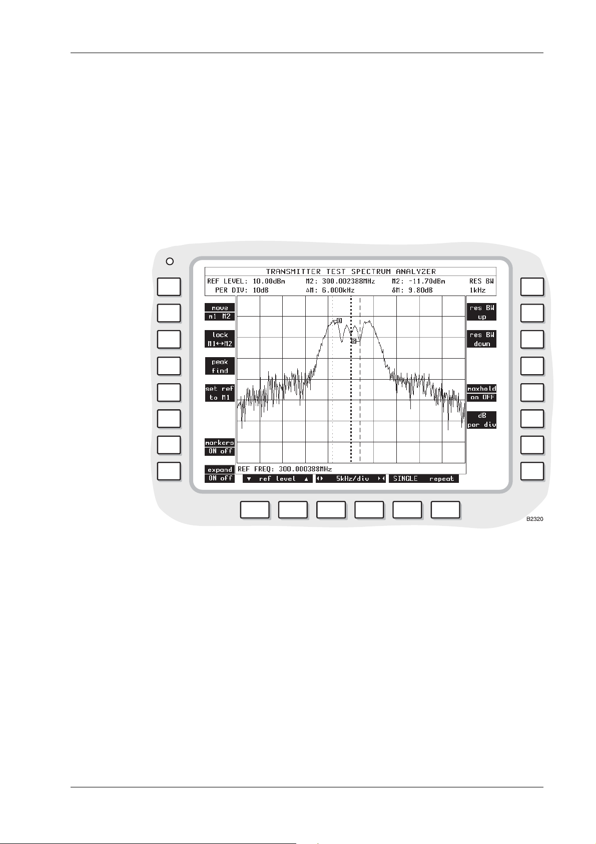
2965A/66A/67/68 RADIO TEST SET
Reference frequency increments can be set and/or adjusted by pressing the [REF] then
[FREQ] then [INC] function keys to highlight the display’s REF FREQ ΔINC legend, then
entering the required increment using the DATA keys, followed by the appropriate [MHz],
[kHz] or [Hz] DATA key.
When the [markers on OFF] soft key is pressed, the following measurements are shown:(a) M1 or M2 frequency. The frequency at the M1 marker (dotted) or M2 marker (dashed) as
set by using the [move m1 m2] soft key and the VARIABLE control.
(b) M1 or M2 level. The level at the above marker.
(c) ΔM. The difference between frequencies of M1 and M2 markers.
(d) δM. The difference between levels of M1 and M2 markers.
Note: The markers become active immediately when the [markers on OFF] key is pressed.
Fig. 3-8 TRANSMITTER TEST SPECTRUM ANALYZER expanded display with markers
Soft keys at left side of screen
The following keys are shown at the left side of the screen:(a) [move m1 m2] key. To show a dotted marker line (M1) or dashed marker line (M2). Each
can be moved by rotating the VARIABLE control (33). This key appears only when the
[markers on OFF] key is pressed.
ÅÆ
(b) [lock M1
[unlock M1
M2] key. To move the two marker lines together. The legend changes to
ÅÆ
M2]. This key appears only when the [markers on OFF] key is pressed.
(c) [peak find] key. To move the dotted marker line (M1) to the frequency at which the level is
peak. This key appears only when the [markers on OFF] key is pressed. Note that peak
find also operates on a single-shot trace without forcing a new sweep.
(d) [set ref to M1] key. To set the reference frequency to that at the position of the dotted
marker (M1). This key appears only when the [markers on OFF] key is pressed.
(e) [markers on OFF] key. To show the above measurements and soft keys.
(f) [expand ON off] key. To revert to the TRANSMITTER TEST display.
46882/274 3-29
Page 91

OPERATION
Soft keys at right side of screen
The following keys may be shown at the right side of the screen:(a) [res BW up] key. To increase the passband of the resolution bandwidth filtering. This key is
not displayed when the resolution bandwidth is set to its maximum, (3 MHz).
(b) [res BW down] key. To decrease the passband of the resolution bandwidth filtering. This
key is not displayed when the resolution bandwid th is set to its minimum.
(c) [res BW auto] key. To enable the automatic selection of the resolution bandwidth filtering.
This key is not displayed when the automatic selection is active. The resolution bandwidth is
dependent on the frequency span/division setting of the display.
(d) [maxhold on OFF] To hold the display so that frequency components of the current scan are
only displayed if they are greater in level than the equivalent frequency components on
previous scans.
(e) [dB per div] To set the vertical resolution to 1, 2, 5 or 10 dB per division. The current dBm
levels are shown on the left side of the display except when the [markers on OFF] soft key
is pressed.
The following table shows the resolution bandw idth filter that is selected when in auto mode.
Column A, lists all available span settings.
Column B, shows the video filter that is automatically set with the span setting.
Column C shows the minimum resolution bandwidth filter that may be manually selected with that
span setting.
Column D shows the resolution bandwidth filter that is set when auto selection is active.
Column E shows the sweep speed when auto selection of ban dwidth filtering is active.
Table 3-1 Spectrum analyzer filtering
Freq/div spans
A
500 Hz 100 Hz Any 300 Hz 500 ms
1 kHz 1 kHz Any 300 Hz 500 ms
2 kHz 1 kHz Any 1 kHz 200 ms
5 kHz 1 kHz Any 1 kHz 400 ms
10 kHz 3 kHz Any 3 kHz 200 ms
20 kHz 3 kHz Any 3 kHz 200 ms
50 kHz 1 kHz Any 3 kHz 200 ms
100 kHz 3 kHz 1 kHz 10 kHz 200 ms
200 kHz 3 kHz 1 kHz 10 kHz 400 ms
500 kHz 3 kHz 3 kHz 30 kHz 400 ms
1 MHz 3 kHz 3 kHz 30 kHz 400 ms
2 MHz 3 kHz 10 kHz 100 kHz 400 ms
5 MHz 3 kHz 30 kHz 300 kHz 400 ms
10 MHz 3 kHz 30 kHz 300 kHz 500 ms
20 MHz 3 kHz 100 kHz 3 MHz 100 ms
50 MHz 3 kHz 100 kHz 3 MHz 200 ms
100 MHz 3 kHz 100 kHz 3 MHz 400 ms
Video Filter
B
Min Res B/W C Res'n B'width D Sweep Speed
Soft keys at bottom of screen
Three pairs of keys are shown below the screen, as follows:-
E
(a)
ref level keys. To increase and decrease, respectively, the reference level of the
vertical range.
3-30 46882/274
Page 92

2965A/66A/67/68 RADIO TEST SET
(b) and keys. To increase and decrease, respectively, the frequency/division of
horizontal range that is shown.
(c) [single] and [repeat] keys. To initiate a single or repeated scan.
Modulation analyzer
Procedure
Press the [Tx TEST] key (3). One of the TRANSMITTER TEST or OFF-AIR TRANSMITTER
TEST displays appears (whichever was last selected). If an OFF-AIR TRANSMITTER TEST
display is shown, press the [normal Tx test] soft key. If an expanded display has appeared, press
the [Tx TEST] key again. The TRANSMITTER TEST display appears. See Fig. 3-6 on
page 3-22.
er suitable selections and settings as under Transmitter testing - non-expanded, page 3-21.
Ent
Display
Press the [
For t
The following settings are shown:(a) REF LEVEL. The reference level for the modulation analyzer, which is set with either the
The modulation analyzer’s reference level can be adjusted by pressing the [REF] then
(b) δINC. The reference level increment that has been set as described below. The increment is
Reference level increments can be set and/or adjusted by pressing the [REF] then [LEVEL]
(c) PER DIV. The scaling of the graticule that has been set by using the [dB per div] soft key.
(d) REF FREQ. The modulation analyzer’s reference frequency, which can be set as described
The modulation analyzer’s reference frequency can be adjusted by pressing the [REF] then
The reference frequency can be adjusted by two further methods using the marker facilities
or
Note that increments cannot be adjusted using the [REF], [FREQ] sequence while the
mod ana] and [expand on OFF] soft keys. The TRANSMITTER TEST MOD
ANALYZER expanded display appears. See Fig. 3-9 on page 3-32.
he display, set parameters by using the soft keys as below.
ref level soft keys or as described below. If an increment has been set as in (b) below,
then the reference level can be incremented/decremented by pressing the INC δ[×] and [Ø]
keys.
[LEVEL] function keys to highlight the display’s REF LEVEL legend, then entering the
required reference level using the DATA keys. Alternatively, the rotary VARIABLE control
can be used instead of the DATA keys.
used by pressing the INC δ[×] and [Ø] keys.
then [INC] function keys to highlight the display’s REF LEVEL INC legend, then entering
the required increment setting using the DATA keys, followed by the [dB] DATA key.
below. If an increment has been set as in (e) below, then the reference frequency can be
incremented/decremented by pressing the INC ΔFREQ [×] and [Ø] keys.
[FREQ] function keys to highlight the display’s REF FREQ legend, then entering the
required reference frequency using the DATA keys followed by the appropriate [MHz],
[kHz] or [Hz] DATA key. The reference frequency can also be adjusted by using the rotary
VARIABLE control instead of the DATA keys.
that are available after pressing the [markers on OFF] soft key:-
Press [peak find], [set ref to M1] to set the reference to the strongest signal
Select [move M1 m2] and adjust the M1 marker using the rotary VARIABLE control,
then press the [set ref to M1] soft key.
markers are on, though increments already set can be used.
46882/274 3-31
Page 93

OPERATION
(e) ΔINC. The reference frequency increment. If an increment has been set as described below,
then the reference frequency can be incremented/decremented by pressing the INC ΔFREQ
[×] and [Ø] keys.
Reference frequency increments can be set and/or adjusted by pressing the [REF] then
[FREQ] then [INC] function keys to highlight the display’s REF FREQ ΔINC legend, then
entering the required increment using the DATA keys, followed by the appropriate [MHz],
[kHz] or [Hz] DATA key.
When the [markers on OFF] soft key is pressed, the following measurements are shown:(a) M1 or M2 frequency. The frequency at the M1 marker (dotted) or M2 marker (dashed) as
set by using the [move m1 m2] soft key and the VARIABLE control.
(b) M1 or M2 deviation or depth. The modulation at the above marker.
(c) ΔM. The difference between frequencies of M1 and M2 markers.
(d) δM. The difference between levels of M1 and M2 markers (in absolute units and dB).
Fig. 3-9 TRANSMITTER TEST MOD ANALYZER expanded display with markers
Soft keys at left side of screen
The following keys are shown at the left side of the screen:(a) [move m1 m2] key. To show a dotted marker line (M1) or dashed marker line (M2). Each
can be moved by rotating the VARIABLE control (33). This key appears only when the
[markers on OFF] key is pressed.
ÅÆ
(b) [lock M1
[unlock M1
M2] key. To move the two marker lines together. The legend changes to
ÅÆ
M2]. This key appears only when the [markers on OFF] key is pressed.
(c) [peak find] key. To move the dotted marker line (M1) to the frequency at which the
modulation is peak. This key appears only when the [markers on OFF] key is pressed. Note
that peak find also operates on a single-shot trace without forcing a new sweep.
(d) [set ref to M1]. To change the REF FREQ: setting to the frequency of marker M1.
(e) [markers on OFF] key. To show the above measurements and soft keys.
3-32 46882/274
Page 94
2965A/66A/67/68 RADIO TEST SET
(f) [expand ON off] key. To revert to the TRANSMITTER TEST display.
Soft keys at right side of screen
The following keys are shown at the right side of the screen:(a) [maxhold on OFF] key. To hold the display so that frequency components of the current
scan are only displayed if they are greater in level than the equivalent frequency components
on previous scans.
(b) [dB per div] key. To set the vertical resolution to 1, 2, 5 or 10 dB per division. The current
dBm levels are shown on the left side of the display except when the [markers on OFF] soft
key is pressed.
(c) [af swp on OFF] key. To enable the AF sweep function.
The AF sweep function provides a means of examining the AF frequency response of passive
circuits, AF amplifiers, or transmitters.
With the modulation analyzer or audio analyzer mode active, AF gen 2 frequency is repeatedly
stepped through the frequency range of the display at the current gen 2 level. The setting of the
AF generator is arranged to systematically sample the displayed range at different points on
successive sweeps. The frequency range covered by the sweep is from 0 to 20 kHz.
Soft keys at bottom of screen
Three pairs of keys are shown, as follows:(a)
(b)
(c) [single] and [repeat] keys. To initiate a single or repeated scan.
ref level
vertical range.
and keys. To increase and decrease, respectively, the frequency/division of
horizontal range that is shown.
keys. To increase and decrease, respectively, the reference level of the
Off-air transmitter testing - non-expanded
Connections
Connect the transmitter to its own antenna.
A Telescopic Antenna (Part no. 54421/001) is available as an optional accessory. Connect this or
another antenna to the RF TNC socket (36).
If required, connect the transmitter’s AF input connector to the AF GEN OUTPUT socket (37).
Procedure
Press the [Tx TEST] key (3). One of the TRANSMITTER TEST or OFF-AIR TRANSMITTER
TEST displays appears (whichever was last selected). If TRANSMITTER TEST display is
shown, press the [off-air test] soft key. If an expanded display has appeared, press the [Tx TEST]
key again and press the [off-air test] soft key. The OFF-AIR TRANSMITTER TEST display
appears. See Fig. 3-10 on page 3-35.
As requi
(a) Press the [Tx] key (11) and then enter the transmitter’s frequency by using the DATA keys
(b) Enter the type of modulation by using the [mod type] soft key.
(c) To select an AF generator, press the [AF GEN] key (15). On the display, AF1, AF2 or AF3
red, enter suitable selections and settings, as shown on the display, as follows:-
(24) and (26). Alternatively, adjust the frequency with the VARIABLE control (33).
in inverse video shows which of the generators has been selected. To select another
generator, press the [1], [2] or [3] key (24) or press the [display gen] soft key repeatedly.
Enter the frequency and level by using the [FREQ] key (16), the [LEVEL] key (17) and the
DATA keys (24) and (26).
46882/274 3-33
Page 95

OPERATION
Alternatively, adjust the frequency and level by using the VARIABLE control (33). The
output from AF generator 2 is sequential tones when this has been selected on the TONES
menu. See under Signalling codes testing, page 3-99. To enable or disable each AF
or, press the appropriate [gen on OFF] (or [tones on OFF]) soft key.
generat
[tones on OFF] is shown instead of [gen 2 on OFF] when sequential tones has been selected
on the TONES menu.
(d) To enter an increment for Tx frequency or AF frequency, press the [Tx] key (11) or
[AF GEN] key (15), the [FREQ] key (16) and then the [INC] key (20). Enter the increment
by using the DATA keys (24) and (26). Δ appears alongside the active increment. To
increase or decrease the frequency setting, press the appropriate [×] or [Ø] key (32). Only a
single frequency increment can be active. Entering one for Tx disables one for AF and vice
versa.
(e) To enter an increment for AF level, press the [AF GEN] key (15), the [LEVEL] key (17) and
then the [INC] key (20). Enter the increment by using the DATA keys (24) and (26).
δ appears alongside the active increment. To increase or decrease the level setting, press the
appropriate [×] or [Ø] key (32).
(f) To select distortion or signal-to-noise measurement, use the [Tx dist S/N] soft key.
Transmitter distortion and signal-to-noise ratio are measured within the bandw idth of the
display’s FILTER value as set by the [band pass] or [low pass] soft key.
The distortion of the demodulated transmitter is measured at a modulating frequency that is
factory preset to 1 kHz. The distortion measurement frequency can be reset using the HELP
AND SET-UP mode to either a user-defined frequency or to the frequency of AF GEN 1.
Distortion, SINAD or S/N tests cannot be carried out while AF GEN 4 or MOD GEN 4 is
enabled.
To change the frequency of measurement, use the key sequence [HELP SET-UP],
[SET-UP], [TEST OPTIONS], [sinad & distn]. For further information, refer to the section
Help and setting up, page 3-
) To select filters, use the [IF BW], [band pass] and [low pass] soft keys.
(g
Read off the measurements that are shown on the display in numerical form and as bar charts
(using the [bar charts] soft key), oscilloscope display (using the [scope] soft key), spectrum
analyzer display (using the [spec ana] soft key) or modulation analyzer display (using the
[mod ana] soft key).
For the oscilloscope, spectrum analyzer and modulation oscillator displays, set parameters by
using the soft keys beneath the screen.
For the spectrum analyzer display, set the reference frequency. Use the [REF] key (11) and
then enter the frequency.
Automatic tuning is not provided in OFF-AIR TRANSMITTER TEST. Set the REF LEVEL
so that the signal peak is within the top two graticule div isio ns.
132.
3-34 46882/274
Page 96

2965A/66A/67/68 RADIO TEST SET
Display
Fig. 3-10 OFF-AIR TRANSMITTER TEST display with bar charts
The following settings and measurements are shown:(a) Tx FREQ and INC. The transmitter frequency that has been entered and any increment.
(b) OFFST. The difference between the frequency measurement of the transmitter’s output and
the transmitter frequency that has been entered.
(c) POWER. The power measurement of the signal that is induced in the antenna.
(d) IF BW. The bandwidth for th e transmitter power measurement as selected by using the
[IF BW] soft key.
(e) MOD FREQ and FM DEVN, AM DEPTH or ΦM DEVN. The modulation frequency and
deviation or depth measurements of the transmitter’s output.
(f) DISTN or S/N. When one of these is enabled, the distortion or signal-to-noise measurement
of the demodulated signal from the transmitter’s output.
(g) FILTER. The filter for the demodulated signal from the transmitter’s output as selected by
using the [band pass] and [low pass] soft keys.
(h) AF1, AF2, AF3 or AF4 FREQUENCY, INC, LEVEL and INC. The settings on one of the
AF generators as selected by using the [1], [2] or [3] key (24) after the [AF GEN] key (15) or
using the [display gen] soft key. If the wide-range AF generator is enabled, the parameters
of this are shown. AF2 is not shown when sequential tones has been selected on the TONES
menu. When AF1, AF2, AF3 or AF4 is shown in inverse video, the [FREQ] key (16) or the
[LEVEL] key (17) can then be used.
Bar charts
When the [bar charts] soft key is used, the following measurements are shown:(a) POWER IN BAND. The measurement of RF level at the input to RF TNC socket (36).
46882/274 3-35
Page 97

OPERATION
Maximum hold
Modulation level
(b) FM DEVN, AM DEPTH or ΦM DEVN. The modulation deviation or depth measurement of
the transmitter’s output.
(c) DISTN or S/N. When one of these is enabled, the distortion or signal-to-noise measurement
of the demodulated signal from the transmitter’s output.
The bar charts are auto-ranging except when the [hold ranges] soft key is used. The range
designators are then shown in inverse video.
The soft keys beneath the bar charts allow each measurement presentation to indicate actual levels
or maximum levels.
With [max hold ON] selected, the bar chart and the digital readouts of it, will track any rise in the
measured level but will not track downward movement. Pressing the [reset] key will cause the
current level to be displayed before reapplying the maximum hold function. An
the lower right of bar charts that are in the Maximum Hold mode.
With [max hold OFF] selected, the bar chart and the associated digital readouts, will track any
change in the measured level.
The modulation level bar chart is a dual display, showing the positive modulation level on the
right and negative modulation level on the left. A digital reading of the indicated level is shown to
the side of each bar chart.
The digital reading of modulation level show in the top half of the display, as FM DEVN, AM
DEPTH or FM DEVN, is the average of the positive and negative readings.
H is displayed at
Oscilloscope
When the [scope] soft key is used, the graticule and trace show the levels of the demodulated
signal from the signal that is induced in the antenna.
Spectrum analyzer
When the [spec ana] soft key is used, the graticule and trace show the spectrum of the signal that
is induced in the antenna.
At the bottom of the display, the REF FREQ setting is shown.
Modulation analyzer
When the [mod ana] soft key is used, the graticule and trace show the spectrum of the signal that
is induced in the antenna.
At the bottom of the display, the REF FREQ setting is shown.
Soft keys at left side of screen
The following keys are shown at the left side of the screen (unless the wide-range AF
generator/modulation generator has been enabled):-
(a) [mod type] key. To select the type of modulation of the transmitter’s output. The options
are FM DEVN, AM DEPTH and ΦM DEVN.
(b) [display gen] key. To select the AF generator before or after using the [AF GEN] key (15).
Press the key repeatedly to step through 1,2 and 3. AF2 is not available when sequential
tones has been selected on the TONES menu. The frequency and level are shown for the
selected generator. When the [AF GEN] key is used, AF1, AF2 or AF3 appear in inverse
video. The [FREQ] key (16) or the [LEVEL] key (17) can then be used.
(c) [gen 1 on OFF], [gen 2 on OFF] (or [tones on OFF]) and [gen 3 on OFF] keys. To enable
or disable the AF generators. [tones on OFF] is shown instead of [gen 2 on OFF] when
sequential tones has been selected on the tones menu.
(d) [normal Tx test]. To select the normal TRANSMITTER TEST display.
3-36 46882/274
Page 98

2965A/66A/67/68 RADIO TEST SET
(e) [hold ranges], [auto range], [expand ON off], (or [expand on OFF]).
When bar charts are displayed, they can be auto-ranging or manually selected. When this key is
labelled [hold ranges], pressing it will disable the auto-ranging function and cause the keys
beneath the bar charts to become [range up] and [range down] keys.
When it is labelled [auto range], pressing it will enable the auto-ran ging function to the bar charts.
When the spectrum analyzer, modulation analyzer or oscilloscope function is active, this key
becomes [expand ON off] or [expand on OFF] and will toggle between the expanded and normal
mode of each.
When the wide-range AF generator/modulation generator has been selected, only the following
soft keys are shown at the left side of the screen:-
(a) [mod type] key. As above.
(b) [display gen] key. As above.
(c) [afgens 1 to 3] key. Pressing this key will cause the message
again to continue. Press any other key to cancel to be displayed.
If the key is pressed again, the wide-range AF generator/modulation generator will be
disabled and AF generators 1 to 3, and modulation generators 1 to 3 will be enabled. The
wide-range AF generator/modulation generator can only be enabled again through the HELP
AND SET-UP menus.
(d) [gen 4 ON off] key. Repeatedly pressing this k ey will alternately turn the wide-range AF
generator on and off. If the wide-range MODULATION generator is in the ON condition,
pressing this key will turn it off, and turn the wide-range AF generator on. But pressing this
key to turn the wide-range AF generator off will not turn the wide-range modulation
generator on.
(e) [normal Tx test] key. As above.
(f) [hold ranges], [auto range], [expand ON off] or [expand on OFF] key. As above.
ARE YOU SURE?. Press key
Soft keys at right side of screen
The following keys are shown at the right side of the screen:(a) [IF BW] key. To select the IF bandwidth. Values of 300 Hz, 1 kHz, 3 kHz, 10 kHz, 30 kHz,
110 kHz, 280 kHz and 3 MHz are available. Press the soft key repeatedly until the required
value is shown on the display.
(b) [band pass] key. To select a band-pass filter for the demodulated signal from the
transmitter’s output. The options are 0.3 to 3.4 kHz and CCITT or CMESS (shown in
inverse video). 0.3 to 3.4 kHz is automatically selected when distortion or SINAD testing is
enabled. This cancels a previous selection using the [low pass] key. CCITT or CMESS is
set by using the key sequence [HELP SET-UP], [SET-UP], [TEST OPTIONS],
[filter options], [psoph filter]. See under Test options, page 3-
low pass] key. To select a low-pass filter for the demodulated signal from the transmitter’s
(c) [
131.
output. The options are 20 kHz LP, 5 kHz LP, 300 Hz LP (shown in inverse video) and
NONE (shown in inverse video). This cancels a previous selection using the [band pass]
key.
(d) [Tx dist S/N] key. To enable or disable distortion or signal-to-noise measurement of the
demodulated signal from the transmitter’s output. Press the key repeatedly for distortion,
S/N or none. When appropriate, DISTN or S/N and a bar chart appear.
(e) [bar charts], [spec ana], [mod ana] and [scope] keys. To select a bar chart, spectrum
analyzer, modulation analyzer or oscilloscope display. The three keys change according to
the current selection.
Soft keys at bottom of screen
When the bar charts display has been selected and the [hold ranges] soft key is used, two keys are
shown below each bar chart, as follows:-
46882/274 3-37
Page 99

OPERATION
(a) [range down] key. To increase the sensitivity.
(b) [range up] key. To decrease the sensitivity.
When the oscilloscope display has been selected, three pairs of keys are sho wn, as follows:(a)
(b)
(c) [single] and [repeat] keys. To initiate a single or repeated scan.
When the spectrum analyzer or modulation analyzer display has been selected, three pairs of keys
are shown, as follows:(a) Ref level
(b)
(c) [single] and [repeat] keys. To initiate a single or repeated scan.
and keys. To increase and decrease, respectively, the level/division of vertical range
that is shown.
and keys. To increase and decrease, respectively, the time/division of horizontal
range that is shown.
and keys. To increase and decrease, respectively, the level, deviation or
depth which is shown.
and keys. To increase and decrease, respectively, the frequency/division of
horizontal range that is shown.
Off-air transmitter testing - expanded
Connections
As under Off-air transmitter testing - non-expanded, page 3-33.
Oscilloscope
Procedure
Press the [Tx TEST] key (3). One of the TRANSMITTER TEST or OFF-AIR TRANSMITTER
TEST displays appears (whichever was last selected). If a TRANSMITTER TEST display is
shown, press the [off-air test] soft key. If an expanded display has appeared, press the [Tx TEST]
key again and press the [off-air test] soft key. The OFF-AIR TRANSMITTER TEST display
appears. See Fig. 3-10 on page 3-35.
Proceed as under Transmitter testing - expanded, page 3-26.
Display
As under Transmitter testing - expanded, page 3-27.
Spectrum analyzer
Procedure
Press the [Tx TEST] key (3). One of the TRANSMITTER TEST or OFF-AIR TRANSMITTER
TEST displays appears (whichever was last selected). If a TRANSMITTER TEST display is
shown, press the [off-air test] soft key. If an expanded display has appeared, press the [Tx TEST]
key again and press the [off-air test] soft key. The OFF-AIR TRANSMITTER TEST display
appears. See Fig. 3-10 on page 3-35.
Proceed as under Transmitter testing - expanded, page 3-28.
Display
As under Transmitter testing - expanded, page 3-28.
3-38 46882/274
Page 100

2965A/66A/67/68 RADIO TEST SET
Modulation analyzer
Procedure
Press the [Tx TEST] key (3). One of the TRANSMITTER TEST or OFF-AIR TRANSMITTER
TEST displays appears (whichever was last selected). If a TRANSMITTER TEST display is
shown, press the [off-air test] soft key. If an expanded display has appeared, press the [Tx TEST]
key again and press the [off-air test] soft key. The OFF-AIR TRANSMITTER TEST display
appears. See Fig. 3-10 on page 3-35.
Proceed as under Transmitter testing - expanded, page 3-31.
Display
As under Transmitter testing - expanded, page 3-31.
46882/274 3-39
 Loading...