

Page 1

Contents
SPECTRUM ANALYZER
2399C
Operating Manual
Document part no. 46892/690
Page 2

SPECTRUM ANALYZER
2399C
Operating Manual
© Aeroflex International Ltd. 2007
No part of this document may be reproduced or transmitted in any form
or by any means, electronic or mechanical, including photocopying,
or recorded by any information storage or retrieval system,
without permission in writing by Aeroflex International Ltd.
(hereafter referred to throughout the document as ‘Aeroflex’).
Manual part no. 46892/690 (PDF version)
Based on Issue 2 of the printed manual
25 July 2007
Page 3

Page 4

Read this manual before using the equipment.
Keep this manual with the equipment
Page 5

Safety Symbols
Where these symbols or indications appear on the equipment or in this manual, they
have the following meanings.
WARNING
.
CAUTION.
GROUND.
Risk of hazard which cause injury to human body or danger to
life, If a WARNING appears on the equipment, and in this
manual, do not proceed until its suitable conditions are
understood and met
Risk of hazard that caused fire or serious damage to the
equipment or other equipment. Do not proceed until its
suitable conditions are met.
Ground terminal to chassis (earth).
2
Page 6

Repair
WARNING
Falling Over
For Symbols
1.
ALWAYS refer to the operation manual when working near
locations at which the alert mark shown on the left is attached. If
the operation, etc., is performed without heeding the advice in the
operation manual, there is a risk of personal injury. In addition, the
equipment performance may be reduced.
Moreover, this alert mark is sometimes used with other marks and
descriptions indicating other dangers.
2. When supplying power to this equipment, connect the accessory
3-pin power cord to a 3-pin grounded power outlet. If a grounded
3-pin outlet is not available, use a conversion adapter and ground
the green wire, or connect the frame ground on the rear panel of
the equipment to ground. If power is supplied without grounding
the equipment, there is a risk of receiving a severe or fatal electric
shock and equipment damage.
3. The user cannot repair this equipment. DO NOT attempt to open
the cabinet or to disassemble internal parts. Only trained service
personnel or staff from your sales representative with knowledge
of electrical fire and shock hazards should service this equipment.
There are high-voltage parts in this equipment presenting a risk of
severe injury or fatal electric shock to untrained personnel. In
addition, there is a risk of damage to internal parts.
4. This equipment should be used in the correct position, If the
cabinet is turned on its side, etc., it will be unstable and may be
damaged if it falls over as a result of receiving a slight mechanical
shock.
WARNING
3
Page 7

Changing Fuse
CAUTION
Cleaning
Check
Terminal
For Symbols
1. Before changing the fuses, ALWAYS remove the power cord from
the power-outlet and replace the blown fuses. ALWAYS use new
fuses of the type and rating specified on the fuse marking on the
rear panel cabinet.
T3.15A indicates a time-lag fuse.
There is risk of receiving a fatal electric shock if the fuses are
replaced with the power cord connected.
2. Keep the power supply and cooling fan free of dust.
Clean the power inlet regularly. If dust accumulates around
the power pins, there is a risk of fire.
Keep the cooling fan clean so that the ventilation holes are not
obstructed. If the ventilation is obstructed, the cabinet may
overheat and catch fire.
3.
○ Maximum DC voltage ratings :
RF Input connector : ±50 VDC
TG Output connector : 0 VDC
○ Maximum RF power ratings :
RF Input power : +30 dBm
○ NEVER input > +30 dBm and >50 VDC power to RF Input.
○ Excessive power may damage the internal circuits.
CAUTION
4
Page 8

5
Page 9

Replacing Memory
Backup Battery
CAUTION
Storage
Medium
CAUTION
For Symbols
CAUTION
4. A Primary Lithium Battery supplies the power for CMOS backup.
This battery should only be replaced by a battery of the same
type ; since Aeroflex can only make replacement, contact the
nearest Aeroflex representative when replacement is required.
Note : The battery life is about 7 years. Early battery replacement
is recommended
Do not throw the battery away but dispose of it according to your
country’s requirement.
5. This equipment stores data and programs using USB Port in the
USB Storage or USB Floppy.
Data and programs may be lost due to improper use or failure.
Aeroflex therefore recommends that you back-up the memory.
(USB Port cannot support an USB Keyboard & Mouse.)
Aeroflex CANNOT COMPENSATE FOR ANY MEMORY LOSS.
6. Use Proper Power Source : Do not operate this product from a
power source that applies more than the voltage specified.
Provide Proper Ventilation : To prevent product overheating,
provide proper ventilation.
6
Page 10

CAUTION
Product Damage
Precaution
For Symbols
Do Not Operate With Suspected Failures : If you suspect there is
Place-related
Warning
damage to this product, have it inspected by qualified service
personnel.
Do Not Attempt To Operate If Protection May Be Impaired : If the
equipment appears damaged or operated abnormally, protection
may be impaired. Do not attempt to operate the equipment under
these conditions. Refer all questions of proper equipment
operation to qualified service personnel.
7. Object and Liquid Entry : Never push objects of any kind into
equipment through openings as they may touch dangerous
voltage points or short out parts that could result in a fire or
electric shock. Never spill liquid of any kind on the equipment.
Do not use this equipment near water– for example, near a
bathtub, wash bowl, kitchen sink, or laundry tub, in a wet
basement, or near a swimming pool, and the like. Keep the
equipment away from damp air, water and dust. Unexpected
trouble may be caused when the equipment is placed in a damp
or dusty place.
Flammable and Explosive Substance : Avoid using this equipment
where there are gases, and where there are flammable and
explosive substances in the immediate vicinity.
Unstable Location : Do not place this equipment on an unstable
cart, stand, tripod, bracket, or table. This equipment may fall,
causing serious injury to a person, and serious damage to the
equipment. Do not place or use the equipment in a place subject
to vibration.
7
Page 11

Precautions
These terms have specific meanings in this manual:
WARNING
Symbols
information to prevent personal injury.
information to prevent damage to the equipment.
important general information.
The meaning of hazard symbols appearing on the equipment and in the documentation is as
follows:
Symbol Description
Refer to the operating manual when this symbol is marked on
the instrument. Familiarize yourself with the nature of the
hazard and the actions that may have to be taken.
Dangerous voltage
Toxic hazard
Static sensitive components
General conditions of use
This product is designed and tested to comply with the requirements of IEC/EN61010-1
‘Safety requirements for electrical equipment for measurement, control and laboratory use’, for
Class I portable equipment and is for use in a pollution degree 2 environment. The equipment
is designed to operate from an installation category II supply.
Equipment should be protected from the ingress of liquids and precipitation such as rain, snow,
etc. When moving the equipment from a cold to a hot environment, it is important to allow
the temperature of the equipment to stabilize before it is connected to the supply to avoid
condensation forming. The equipment must only be operated within the environmental
conditions specified in Chapter 1 in the Operating Manual, otherwise the protection provided
by the equipment may be impaired.
8
Page 12

This product is not approved for use in hazardous atmospheres or medical applications. If the
equipment is to be used in a safety-related application, e.g. avionics or military applications,
the suitability of the product must be assessed and approved for use by a competent person.
WARNING
Electrical hazards (AC supply voltage)
WARNING
This equipment conforms with IEC Safety Class I, meaning that it is provided with a
protective grounding lead. To maintain this protection the supply lead must always be
connected to the source of supply via a socket with a grounded contact.
Be aware that the supply filter contains capacitors that may remain charged after the
equipment is disconnected from the supply. Although the stored energy is within the
approved safety requirements, a slight shock may be felt if the plug pins are touched
immediately after removal.
Do not remove instrument covers as this may result in personal injury. There are no userserviceable parts inside.
Refer all servicing to qualified personnel. See list of Service Centers at rear of manual.
Fire hazard
Make sure that only fuses of the correct rating and type are used for replacement.
If an integrally fused plug is used on the supply lead, ensure that the fuse rating is
commensurate with the current requirements of this equipment.
9
Page 13

WARNING
WARNING
Beryllium copper
Toxic hazards
Some of the components used in this equipment may include resins and other materials which
give off toxic fumes if incinerated. Take appropriate precautions, therefore, in the disposal of
these items.
Some mechanical components within this instrument are manufactured from beryllium copper.
This is an alloy with a beryllium content of approximately 5%. It represents no risk in normal
use.
The material should not be machined, welded or subjected to any process where heat is
WARNING
Lithium
involved.
It must be disposed of as “special waste”.
It must NOT be disposed of by incineration.
A Lithium battery (or a Lithium battery contained within an IC) is used in this equipment.
As Lithium is a toxic substance, the battery should in no circumstances be crushed, incinerated
or disposed of in normal waste.
Do not attempt to recharge this type of battery. Do not short circuit or force discharge since
this might cause the battery to vent, overheat or explode.
10
Page 14

WARNING
Tilt facility
When the equipment is in the tilt position, it is advisable, for stability reasons, not to stack
other equipment on top of it.
Static sensitive components
This equipment contains static sensitive components which may be damaged by handling —
refer to the Maintenance part of the Service Manual for handling precautions.
Precision connector
The precision microwave connectors fitted to this equipment may be damaged by mating with
a non-precision type. Damage to the connector may also occur if the connector interface
parameters are not within specification. The connector should be checked with the
appropriate gauging tool.
Suitability for use
This equipment has been designed and manufactured by Aeroflex to perform measurements on
RF and microwave components and systems.
If the equipment is not used in a manner specified by Aeroflex, the protection provided by the
equipment may be impaired.
Aeroflex has no control over the use of this equipment and cann ot be hel d resp o nsibl e fo r
events arising from its use other than for its intended purpose.
11
Page 15

Précautions
Les termes suivants ont, dans ce manuel, des significations particulières:
WARNING
contient des informations pour éviter toute blessure au personnel.
contient des informations pour éviter les dommages aux équipements.
contient d’importantes informations d’ordre général.
Symboles signalant un risque
La signification des symboles de danger apparaissant sur l'équipement et dans la
documentation est la suivante:
Symbole Nature du risque
Reportez-vous au manuel d'utilisation quand ce symbole
apparaît sur l'instrument. Familiarisez-vous avec la nature
du danger et la conduite à tenir.
Tension dangereuse
Danger produits toxiques
Conditions générales d’utilisation
Ce produit a été conçu et testé pour être conforme aux exigences des normes CEI/EN61010-1
12
“Règles de sécurité pour appareils électriques de mesurage, de régulation et de laboratoire”,
pour des équipements Classe I portables et pour une utilisation dans un environnement de
pollution de niveau 2. Cet équipement est conçu pour fonctionner à partir d’une alimentation
de catégorie II.
Cet équipement doit être protégé de l’introduction de liquides ainsi que des précipitation s
d’eau, de neige, etc... Lorsqu’on transporte cet équipement d’un environnement chaud vers
un environnement froid, il est important de laisser l’équipement se stabiliser en température
avant de le connecter à une alimentation afin d’éviter toute formation de condensation.
L'appareil doit être utilisé uniquement dans le cadre des conditions d'environnement spécifiées
au chapitre 1 ‘Performance data’ du manuel d'utilisation, toute autre utilisation peut
endommager les systèmes de protection.
Page 16

Ce produit n’est pas garanti pour foncti o nner dans des atmosphères dangereuses ou po ur un
usage médical. Si l'équipement doit être utilisé pour des applications en relation avec la
sécurité, par exemple des applications militaires ou aéronautiques, la compatibilité du produit
doit être établie et approuvée par une personne compétente.
WARNING
Sécurité électrique (tension d’alimentation alternative)
Cet appareil est protégé conformément à la norme CEI de sécurité Classe 1, c’est-à-dire que sa
prise secteur comporte un fil de protection à la terre. Pour maintenir cette protection, le câble
d’alimentation doit toujours être branché à la source d’alimentation par l’intermédiaire d’une
prise comportant une borne de terre.
Notez que les filtres d’alimentation contiennent des condensateurs qui peuvent encore être
chargés lorsque l’appareil est débranché. Bien que l’énergie contenue soit conforme aux
exigences de sécurité, il est possible de ressentir un léger choc si l’on touche les bornes sitôt
après débranchement.
Ne démontez pas le capot de l'instrument, car ceci peut provoquer des blessures. Il n'y a pas
de pièces remplaçables par l'utilisateur à l'intérieur.
Faites effectuer toute réparation par du personnel qualifié. Contacter un des Centres de
Maintenance Internationaux dans la liste jointe à la fin du manuel.
WARNING
Risque lié au feu
Lors du remplacement des fusibles vérifiez l’exactitude de leur type et de leur valeur.
Si le câble d’alimentation comporte une prise avec fusible intégré, assurez vous que sa valeur
est compatible avec les besoins en courant de l’appareil.
WARNING
Danger produits toxiques
Certains composants utilisés dans cet appareil peuvent contenir des résines et d’autres matières
qui dégagent des fumées toxiques lors de leur incinération. Les précautions d’usages doivent
donc être prises lorsqu’on se débarrasse de ce type de composant.
13
Page 17

WARNING
Bronze au béryllium
WARNING
Dans cet équipement,certaines pièces mécaniques sont à base de bronze au béryllium. Il s'agit
d'un alliage dans lequel le pourcentage de béryllium ne dépasse pas 5%. Il ne présente aucun
danger en utilisation normale.
Toutefois, cet alliage ne doit pas être travaillé, soudé ou soumis à un processus qui implique
l'utilisation d'une source de chaleur.
En cas de destruction, il sera entreposé dans un container spécial. IL ne devra pas être détruit
par incinération
Lithium
Une pile au Lithium ou un CI contenant une pile au Lithium est utilisé dans cet équipement.
Le Lithium étant une substance toxique, il ne faut en aucun cas l’écraser, l’incinérer ou le jeter
avec des déchets normaux.
N’essayez pas de recharger ce type de pile. Ne court-circuitez pas ou ne forcez pas la
décharge de la pile car cela pourrait causer une fuite, une surchauffe ou une explosi on .
WARNING
Position inclinée
Utilisation
Lorsque l’appareil est dans une position inclinée, il est recommandé, pour des raisons de
stabilité, de ne pas y empiler d’autres appareils.
Cet équipement a été conçu et fabriqué par Aeroflex pour effectuer des mesures sur des
composants et des systèmes RF et hyperfréquences
La protection de l'équipement peut être altérée s'il n'est pas utilisé dans les conditions
spécifiées par Aeroflex.
Aeroflex n'a aucun contrôle sur l'usage de l'instrument, et ne pourra être tenu pour responsable
en cas d'événement survenant suite à une utilisation différente de celle prévue.
14
Page 18

Vorsichtsmaßnahmen
Diese Hinweise haben eine bestimmte Bedeutung in diesem Handbuch:
WARNING
dienen zur Vermeidung von Verletzungsrisiken.
dienen dem Schutz der Geräte.
enthalten wichtige Informationen.
Gefahrensymbole
Die Bedeutung der Gefahrensymbole auf den Geräten und in der Dokumentation ist wie folgt:
Symbol Gefahrenart
Beziehen Sie sich auf die Bedienungsanleitung wenn das
Messgerät mit diesem Symbol markiert ist. Machen Sie
sich mit der Art der Gefahr und den Aktionen die getroffen
werden müssen bekannt.
Gefährliche Spannung
Warnung vor giftigen Substanzen
Allgemeine Hinweise zur Verwendung
Dieses Produkt wurde entsprechend den Anforderungen von IEC/EN61010-1
“Sicherheitsanforderungen für elektrisc he Ausr üst u n g für M e ßaufgaben, Steuerung und
Laborbedarf”, Klasse I transportabel zur Verwendung in einer Grad 2 verunreinigten
Umgebung, entwickelt und getestet. Dieses Gerät ist für Netzversorgung Klasse II
zugelassen.
Das Gerät sollte vor dem Eindringen von Flüssigkeiten sowie vor Regen, Schnee etc. geschützt
werden. Bei Standortänderung von kalter in wärmere Umgebung sollte das Gerät wegen der
Kondensation erst nach Anpassung an die wärmere Umgebung mit dem Netz verbunden
werden. Das Gerät darf nur in Umgebungsbedingungen wie im Kapitel 1 ‘Lesitungstdaten
(Performance data)’ der Bedienungsanleitung beschrieben, betrieben werden; ansonsten wird
der vom Gerät vorgesehene Schutz des Anwenders beei nträchtigt.
15
Page 19

Dieses Produkt ist nicht für den Einsatz in gefährlicher Umgebung (z.B. Ex-Bereich) und für
medizinische Anwendungen geprüft. Sollte das Gerät für den Einsatz in sicherheitsrelevanten
Anwendungen wie z.B. im Flugverkehr oder bei militaerischen Anwendungen vorgesehen
sein, so ist dieser von einer für diesen Bereich zuständigen Person zu beurteilen und
genehmigen.
WARNING
Elektrische Schläge (Wechselspannungsversorgung)
WARNING
Das Gerät entspricht IEC Sicherheitsklasse 1 mit einem Schutzleiter nach Erde. Das
Netzkabel muß stets an eine Steckdose mit Erdkontakt angeschlossen werden.
Filterkondensatoren in der internen Spannungsversorgung können auch nach Unterbrechung
der Spannungszuführung noch geladen sein. Obwohl die darin gespeicherte Energie innerhalb
der Sicherheitsmargen liegt, kann ein leichter Spannungsschlag bei Berührung kurz nach der
Unterbrechung erfolgen.
Öffnen Sie niemals das Gehäuse der Geräte das dies zu ernsthaften Verletzungen führen kann.
Es gibt keine vom Anwender austauschbare Teile in diesem Gerät.
Lassen Sie alle Reparaturen durch qualifiziertes Personal durchführen. Eine Liste der
Servicestellen finden Sie auf der Rückseite des Handbuches.
Feuergefahr
Es dürfen nur Ersatzsicherungen vom gleichen Typ mit den korrekten Spezifikationen
entsprechend der Stromaufnahme des Gerätes verwendet werden.
16
Page 20

WARNING
Warnung vor giftigen Substanzen
WARNING
Beryllium Kupfer
In einigen Bauelementen dieses Geräts können Epoxyharze oder andere Materialien en thalten
sein, die im Brandfall giftige Gase erzeugen. Bei der Entsorgung müssen deshalb
entsprechende Vorsichtsmaßnahm en getr of fen werden.
In diesem Gerät sind einige mechanische Komponenten aus Berylium Kupfer gefertigt. Dies
ist eine Verbindung welche aus einem Berylliumanteil von ca. 5 % besteht. Bei normaler
Verwendung besteht kein Gesundheitsrisiko.
Das Metall darf nicht bearbeitet, geschweißt oder sonstiger Wärmebehandlung ausgesetzt
werden.
Es muß als Sondermüll entsorgt werden.
Es darf nicht durch Verbrennung entsorgt werden.
WARNING
WARNING
Schrägstellung
Lithium
Eine Lithium Batterie oder eine Lithium Batterie innerhalb eines IC ist in diesem Gerät
eingebaut.
Da Lithium ein giftiges Material ist, sollte es als Sondermüll entsorgt werden.
Diese Batterie darf auf keinen Fall geladen werden. Nicht kurzschließen, da sie dabei
überhitzt werden und explodieren kann.
Bei Schrägstellung des Geräts sollten aus Stabilitätsgründen keine and eren Geräte darauf
gestellt werden.
17
Page 21

Eignung für Gebrauch
Dieses Gerät wurde von Aeroflex entwickelt und hergestellt um Messungen an HF- und
Mikrowellenkomponenten und -Systemen durchzuführen
Sollte das Gerät nicht auf die von Aeroflex vorgesehene Art und Weise verwendet werden,
kann die Schutzfunktion des Gerätes beeinträchtigt werden.
Aeroflex hat keinen Einfluß auf die Art der Verwendung und übernimmt keinerlei
Verantwortung bei unsachgemässer Handhabung.
18
Page 22

Precauzioni
Questi termini vengono utilizzati in questo manuale con significati specifici:
WARNING
riportano informazioni atte ad evitare possibili pericoli alla persona.
riportano informazioni per evitare possibili pericoli all'apparecchiatura.
riportano importanti informazioni di carattere generale.
Simboli di pericolo
Il significato del simbolo di pericolo riportato sugli strumenti e nella documentazione è il
seguente:
Simbolo
Tipo di pericolo
Fare riferimento al manuale operativo quando questo
simbolo è riportato sullo strumento. Rendervi conto della
natura del pericolo e delle precauzioni che dovrete
prendere.
Tensione pericolosa
Pericolo sostanze tossiche
Condizioni generali d’uso
Questo prodotto è stato progettato e collaudato per rispondere ai requisiti della direttiva
IEC/EN61010-1 ‘Safety requirements for electrical equipment for measurement, control and
laboratory use’ per apparati di classe I portatili e per l’uso in un ambiente inquinato di grado 2.
L’apparato è stato progettato per essere alimentato da un alimentatore di categoria II.
Lo strumento deve essere protetto dal possibile ingresso di liquidi quali, ad es., acqua, pioggia,
neve, ecc. Qualora lo strumento venga portato da un ambiente freddo ad uno caldo, è
importante lasciare che la temperatura all’interno dello strumento si stabilizzi prima di
alimentarlo per evitare formazione di condense. Lo strumento deve essere utilizzato
esclusivamente nelle condizioni ambientali descritte nel capitolo 1 ‘Performance data’ del
manuale operativo, in caso contrario le protezioni previste nello strumento potrebbero risultare
non sufficienti.
19
Page 23

Questo prodotto non è stato approvato per essere usato in ambienti pericolosi o applicazioni
medicali. Se lo strumento deve essere usato per applicazioni particolari collegate alla
sicurezza (per esempio applicazioni militari o avioniche), occorre che una persona o un istituto
competente ne certifichi l'uso.
WARNING
Pericoli da elettricità (alimentazione c.a.)
Quest ’apparato è provvisto del collegamento di protezione di terra e rispetta le norme di
sicurezza IEC, classe 1. Per mantenere questa protezione è necessario che il cavo, la spina e
la presa d’alimentazione siano tutti provvisti di terra.
Il circuito d’alimentazione contiene dei filtri i cui condensatori possono restare carichi anche
dopo aver rimosso l’alimentazione. Sebbene l’energia immagazzinata è entro i limiti di
sicurezza, purtuttavia una leggera scossa può essere avvertita toccando i capi della spina subito
dopo averla rimossa.
Non rimuovete mai le coperture perché così potreste provocare danni a voi stessi. Non vi
sono all’interno parti di interesse all’utilizzatore.
Tutte gli interventi sono di competenza del personale qualificato. Vedi elenco internazionale
dei Centri di Assistenza in fondo al manuale.
WARNING
Pericolo d’incendio
Assicurarsi che, in caso di sostituzione, vengano utilizzati solo fusibili della portata e del tipo
prescritti.
Se viene usata una spina con fusibili, assicurarsi che questi siano di portata adeguata ai
requisiti di alimentazione richiesti dallo strumento.
20
Page 24

WARNING
Pericolo sostanze tossiche
WARNING
Alcuni dei componenti usati in questo strumento possono contenere resine o altri materiali che,
se bruciati, possono emettere fumi tossici. Prendere quindi le opportune precauzioni nell’uso
di tali parti.
Rame berillio
Alcuni componenti meccanici in questo strumento sono realizzati in rame berillio. Si tratta di
una lega con contenuto di berillio di circa il 5%, che non presenta alcun rischio in usi normali.
Questo materiale non deve essere lavorato, saldato o subire qualsiasi processo che coinvolge
alte temperature.
Deve essere eliminato come "rifiuto speciale". Non deve essere eliminato tramite
WARNING
Litio
"inceneritore".
Quest ’apparato incorpora una batteria al litio o un circuito integrato contenente una batteria al
litio.
Poiché il litio è una sostanza tossica, la batteria non deve essere mai né rotta, né incenerita, né
gettata tra i normali rifiuti.
Questo tipo di batteria non può essere sottoposto né a ricarica né a corto-circuito o scarica
forzata. Queste azioni possono provocare surriscaldamento, fuoriuscita di gas o esplosione
della batteria.
21
Page 25

WARNING
Posizionamento inclinato
Quando lo strumento è in posizione inclinata è raccomandato, per motivi di stabilità, non
sovrapporre altri strumenti.
Caratteristiche d’uso
Questo strumento è stato progettato e prodotto da Aeroflex eseguire misure su componenti o
sistemi RF e microonde
Se lo strumento non è utilizzato nel modo specificato da Aeroflex, le protezioni previste sullo
strumento potrebbero risultare inefficaci.
Aeroflex non può avere il controllo sull’uso di questo strumento e non può essere ritenuta
responsabile per eventi risultanti da un uso diverso dallo scopo prefisso.
22
Page 26

Precauciones
WARNING
Estos términos tienen significados específicos en este manual:
contienen información referente a prevención de daños personales.
contienen información referente a prevención de daños en equipos.
contienen información general importante.
Símbolos de peligro
El significado de los símbolos de peligro en el equipo y en la documentación es el siguiente:
Símbolo
Naturaleza del peligro
Vea el manual de funcionamiento cuando este símbolo
aparezca en el instrumento. Familiarícese con la
naturaleza del riesgo y con las acciones que deban de
tomarse.
Voltaje peligroso
Aviso de toxicidad
Condiciones generales de uso
Este producto ha sido diseñado y probado para cumplir los requerimientos de la normativa
IEC/EN61010-1 “Requerimientos de la normativa para equipos eléctricos de medida, control y
uso en laboratorio”, para equipos clase I portátiles y para uso en un ambiente con un grado de
contaminación 2. El equipo ha sido diseñado para funcionar sobre una instalación de
alimentación de categorías II.
Debe protegerse el equipo de la entrada de líquidos y precipitaciones como nieve, lluvia, etc.
Cuando se traslada el equipo de entorno frío a un entorno caliente, es importante aguardar la
estabilización el equipo para evitar la condensación. Solamente debe utilizarse el equipo bajo
las condiciones ambientales especificadas en el capítulo 1 “Especificaciones” o “Performance
data” del Manual de Instrucciones, en caso contrario la propia protección del equipo puede
resultar dañada.
23
Page 27

Este producto no ha sido aprobado para su utilización en entornos peligrosos o en aplicaciones
médicas. Si se va a utilizar el equipo en una aplicación con implicaciones en cuanto a
seguridad, como por ejemplo aplicaciones de aviónica o militares, es preciso que un experto
competente en materia de seguridad apruebe su uso.
WARNING
Nivel peligroso de electricidad (tensión de red)
Este equipo cumple las normas IEC Seguridad Clase 1, lo que significa que va provisto de un
cable de protección de masa. Para mantener esta protección, el cable de alimentación de red
debe de conectarse siempre a una clavija con terminal de masa.
Tenga en cuenta que el filtro de red contiene condensadores que pueden almacenar carga una
vez desconectado el equipo. Aunque la energía almacenada está dentro de los requisitos de
seguridad, pudiera sentirse una ligera descarga al tocar la clavija de alimentación
inmediatamente después de su desconexi ó n de red .
No retire las cubiertas del chasis del instrumento, ya que pudiera resultar dañado
personalmente. No existen partes que puedan ser reparadas en su interior.
Deje todas las tareas relativas a reparación a un servicio técnico cualificado. Vea la lista de
Centros de Servicios Internacionales en la parte trasera del manual.
Fusibles
Se hace notar que el Equipo está dotado de fusibles tanto en el activo como el neutro de
alimentación. Si sólo uno de estos fusibles fundiera, existen partes del equipo que pudieran
permanecer a tensión de red.
WARNING
Peligro de incendio
Asegúrese de utilizar sólo fusibles del tipo y valores especificados como repuesto.
Si se utiliza una clavija con fusible incorporado, asegúrese de que los valores del fusible
corresponden a los requeridos por el equipo. Consulte la Hoja Técnica (tras el Capítulo 1)
para comprobar los requisitos de alimentación.
24
Page 28

WARNING
Aviso de toxicidad
WARNING
Alguno de los componentes utilizados en este equipo pudieran incluir resinas u otro tipo de
materiales que al arder produjeran sustancias tóxicas, Por tanto, tome las debidas
precauciones en la manipulación de esas piezas.
Berilio-cobre
Algunos componentes mecánicos contenidos en este instrumento incorporan berilio-cobre en
su proceso de fabricación. Se trata de una aleación con un contenido aproximado de berilio del
5%, lo que no representa ningún riesgo durante su us o normal.
El material no debe ser manipulado, soldado, ni sometido a ningún proceso que implique la
aplicación de calor.
WARNING
Litio
Para su eliminación debe tratarse como un "residuo especial". El material NO DEBE
eliminarse mediante incineración.
En este equipo se utiliza una batería de litio (o contenida dentro de un CI).
Dada que el litio es una substancia tóxica las baterías de este material no deben ser aplastadas,
quemadas o arrojadas junto a basuras ordinarias.
No trate de recargar este tipo de baterías. No las cortocircuite o fuerce su descarga ya que
puede dar lugar a que la esta emita gases, se recaliente o explote.
25
Page 29

WARNING
Tener en cuenta con el equipo inclinado
Si utiliza el equipo en posición inclinada, se recomienda, por razones de estabilidad, no apilar
otros equipos encima de él.
Idoneidad de uso
Este equipo ha sido diseñado y fabricado por Aeroflex para realizar medidas en RF y
microondas en componentes y sistemas
Si el equipo fuese utilizado de forma diferente a la especificada por Aeroflex, la protección
ofrecida por el equipo pudiera quedar reducida.
Aeroflex no tiene control sobre el uso de este equipo y no puede, por tanto, exigirsele
responsabilidades derivadas de una utilización distinta de aquellas para las que ha sido
diseñado.
26
Page 30

Aeroflex Warranty
Aeroflex will repair this equipment fee of charge if a malfunction occurs within 2 year after
shipment due to a manufacturing fault, provided that warranty is rendered void under any or
all of the following conditions.
The fault is outside the scope of the warranty conditions described in the operation
manual.
The fault is due to wrong operation, misuse, or unauthorized modification or repair of the
equipment by the customer.
The fault is due to severe usage clearly exceeding normal usage.
The fault is due to improper or insufficient maintenance by the customer.
The fault is due to natural disaster including fire, flooding and earthquake, etc.
The fault is due to use of non-specified peripheral equipment, peripheral parts,
consumables, etc.
The fault is due to use of non specified power supply or in non-specified installation
location.
In addition, this warranty is valid only for the original equipment purchaser. It is not
transferable if the equipment is resold.
Aeroflex will not accept liability for equipment faults due to unforeseen and unusual
circumstances, nor for faults due to mishandling by the customer.
Aeroflex Contact
If this equipment develops a fault, contact office of Aeroflex at the address in the operation
manual, or your nearest sales or service office.
27
Page 31

Front Panel Power Switch
If the equipment is in the standby state, the front power switch of this equipment turns
on the power when it is pressed.
If the switch is pressed continuously for about 1 second in the power off state, the
equipment enters the standby state to prevent malfunction caused by accidental
touching.
In the power on state, if the power plug is removed from the outlet, then reinserted, the
power will not be turned on. Also, if the line is disconnected due to momentary power
supply interruption or power failure, the power will not be turned on even when power is
restored.
This is to prevent incorrect data from being acquired when the line is disconnected and
reconnected.
For example, if the sweep is 1,000 seconds and data acquisition requires a long time,
momentary power supply interruption (power failure) might occur during measurement
and the line could be recovered automatically to power on. In such a case, the
equipment may mistake incorrect data for correct data without recognizing the
momentary power supply interruption.
If this equipment enters the standby state due to momentary power supply interruption or
power failure, check the state of the measuring system and press the front power switch
to restore power to this equipment.
Further, if this equipment is built into a system and the system power has to be
disconnected then reconnected, the power for this equipment must also be restored by
pressing the front power switch.
28
Page 32

DETECTION MODE
This equipment is a spectrum analyzer, which uses a digital storage system. The
spectrum analyzer makes level measurements in frequency steps obtained by dividing
the frequency span by the number of measurement data points (500). Because of this
operation it is desired to use the following detector modes associated with the
appropriate measurements.
Measurement Detector mode
Normal signal POS PEAK
Random noise SAMPLE OR AVERAGE
Pulsed noise NORMAL
Occupied frequency bandwidth SAMPLE
(for analog communication systems)
Occupied frequency bandwidth POS PEAK or SAMPLE
(for digital communication systems)
When a detection mode is specified as one of the measurement methods, make the
measurement in the specified detection mode.
29
Page 33

f
V
p
V
(Op
)
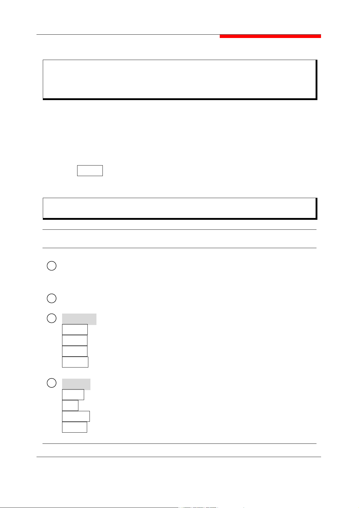
ABOUT THIS MANUAL
Composition of 2399C Manuals
The 2399C Spectrum Analyzer manuals of the standard type are composed of the following
three parts.
Operation Manual : Provides information on the 2399C outline.
Composition
o
Manuals
ol.1
ol.2
O
eration
tions
Measurement Guide
Programming
Preparation before use, panel description,
Operation procedure, soft-key menu and performance tests.
Measurement Guide : Provides basic measurements with examples of typical measurements.
Programming Manual : Provides information on RS-232C remote control, GPIB remote
control and sample programs.
30
Page 34

COMPOSITION OF OPERATION MANUAL
This Manual is composed of 7 sections. The profile of each section is shown below.
Section Composition Explanation
SECTION 1
GENERAL
SECTION 2
PREPARATIONS
BEFORE USE
SECTION 3
PANEL
DESCRIPTION
SECTION 4
MENU TREE
SECTION 5
OPERATION
PROCEDURES
SECTION 6
PERFORMANCE
TESTS
Product outline, options, applicable parts, peripheral
devices, and specifications
Operations to be accomplished before applying power
Description of the front and rear panels
Description of the soft-key menu
Operation procedures for operation guide
Tests used for checking performance
SECTION 7
STORAGE AND
TRANSPORTATION
Cautions on storage and transportation
31
Page 35

SECTION 1
SECTION 1 GENERAL
GENERAL
This section outlines the 2399C (henceforth called “Equipment”) and explains the
composition of this manual, the configuration of the equipment with the options, the optional
accessories, peripherals for expanding the equipment capabilities, and the equipment
specifications.
TABLE OF
CONTENTS
PRODUCT OUTLINE ---------------------------------------------------EQUIPMENT CONFIGURATION ------------------------------------------
Options ---------------------------------------------------------------
SPECIFICATIONS -------------------------------------------------------
1-3
1-4
1-4
1-5
1-1
Page 36

SECTION 1 GENERAL
<BLANK>
1-2
Page 37

SECTION 1
SECTION 1 GENERAL
GENERAL
PRODUCT OUTLINE
The equipment is a portable type spectrum analyzer suited for signal analysis of radio
equipment where the efficiency of frequency usage is increased and equipment is
increasingly speeded and digitized.
The equipment adopts the synthesizer local system and can cover all frequencies from 1
kHz to 3.0 GHz excellent in basic performance such as distortion, frequency/level accuracy,
and easy operation, by following the display of the soft-key menu screen.
Excellent cost performance with rich options to cope with various applications.
Equipped with high accuracy calibration signals and an attenuator, it can accurately calibrate
switching errors of LOG/LIN scales, resolution bandwidth, reference level, etc.
Since frequency response data is corrected by built in calibration data, allowing highaccuracy level measurement for a wide range.
This unit provides the MEASURE function that can perform measurement of various
applications without requiring the intervention of external controllers. Therefore, the
performance evaluation of radio equipment can be easily done in terms of frequency, noise,
occupied frequency bandwidth, etc.
Application
This unit is useful for the production, building and maintenance of electronic equipment
and devices for the following.
AM/FM radio equipment
Digital cellular telephone/cordless telephone
Satellite broadcasting and TV equipment
Small capacity microwave equipment
1-3
Page 38

SECTION 1 GENERAL
EQUIPMENT CONFIGURATION
This paragraph describes the configuration of the equipment with the various options to
expand the functions.
Options
The table below shows the options for the equipment which are sold separately.
Model No. Name Remarks
Option 03
Option 04
Option 05
Option 07
Option 11
Option 12
Option 13
High Stability
Oscillator
Quasi-Peak Detector
Digital RBW 10, 30, 100Hz RBW
Preamplifier
DTF Measurement
personality
Marker Editor Marker name editor
EMC Measurement
Package (Firmware)
Stability : ≤ ±0.2ppm
QP B
QP C/D Quasi-Peak included
Distance to Fault VSWR (Return Loss)
Support Log X scale display.
Limit/Xducer/Cable/Ant/Others
Parameter file management.
Limit line link with graticule.
1-4
Page 39

SPECIFICATIONS
NOTE : A fifteen minute warm up time shall apply.
1.0 FREQUENCY
1.1 Frequency range 1.0 ㎑ to 3.0 ㎓
1.2 Tuning Resolution 1 ㎐ Minimum
1.3 Frequency Span Width 100 ㎐/div to 300 ㎒/div
SECTION 1 GENERAL
In 1, 2, 5 step selections (auto selected) plus ZERO
Span, and FULL Span (9 ㎑ to 3.0 ㎓). Manual
selection of start, stop, and span.
1.4 Span Accuracy ±3% of the indicated Span Width
1.5 Readout Accuracy ≤±(Indicated frequency × reference frequency
accuracy + span × span accuracy + 50% of
RBW)
1.6 Frequency Counter
1.6.1 Resolution 1 ㎑, 100 ㎐, 10 ㎐, 1 ㎐ (user selectable)
1.6.2 Accuracy ≤ ±((Reference frequency accuracy × marker
frequency) + (1(resolution error) + 1(counter error)
× counter resolution))
1-5
Page 40

SECTION 1 GENERAL
1.6.3 Sensitivity ≤ -70dBm (50 ㎑ to 3.0 ㎓)
1.7 Stability
1.7.1 Residual FM ≤ 100 ㎐
P-P in 200 ㎳, 1 ㎑ RBW, 1 ㎑ VBW
1.7.2 Noise Sidebands ≤ -90dBc/㎐ 10 ㎑ offset
2.0 AMPLITUDE
2.1 Measurement Range +30 dBm to average noise level.
2.2 Average Displayed Noise Level : ≤ -105 dBm, 50 ㎑ to 100 ㎑
≤ -110 dBm, 100 ㎑ to 2.8 ㎓
≤ -105 dBm, 2.8 ㎓ to 3.0 ㎓
≤ -130 dBm, 50 ㎒ to 1.8 ㎓ (Preamp operation.)
≤ -128 dBm, 1.8 ㎓ to 3.0 ㎓ (Preamp operation.)
(RBW 1 ㎑, VBW 10 ㎐)
2.3 1dB Compression Point -10 dBm 100 ㎑ to 3.0 ㎓ (0dB attenuation)
2.4 Displayed Range 100 dB in 10 dB/div log scale.
50 dB in 5 dB/div log scale.
20 dB in 2 dB/div log scale.
10 dB in 1 dB/div log scale.
10 divisions with linear amplitude scale.
2.5 Amplitude Units dBm, dB ㎷, dB ㎶, V, ㎷, ㎶, W, ㎽, ㎼
1-6
Page 41

SECTION 1 GENERAL
2.6 Display Linearity
2.6.1 5 or 10dB/div ±0.15 dB/dB, ±1.5 dB over 10 divisions
2.6.2 1 or 2 dB/div ±0.5 dB over 10 divisions
2.6.3 Linear ±10 % of Reference Level over 10 divisions
2.7 Frequency Response -3.0 ∼ +1 dB, 9 ㎑ to 10 ㎒
±1.5 dB, 10 ㎒ to 3.0 ㎓ (10 dB RF attenuation)
2.8 Attenuator
2.8.1 Range 0 to 50 dB, Selected manually or
automatically coupled to reference level.
2.8.2 Resolution 10 dB steps.
2.8.3 Accuracy ±0.5 dB/step, 100 ㎒
±1.5 dB/maximum step, 100 ㎒
2.9 Reference Level
2.9.1 Accuracy ±1.5 dB (50 ㎑ to 3.0 ㎓)
2.9.2 Range -110 dBm to +30 dBm
2.9.3 Resolution 0.1dB
2.10 Residual Spurious ≤ -85 dBm (Input terminated, 0 dB attenuation)
2.11 Harmonic Distortion ≤ -65 dBc, -30 dBm input, 0 dB attenuation
1-7
Page 42

SECTION 1 GENERAL
2.12 3rd order Intermodulation Distortion ≤ -65 dBc, 〈700 ㎒, -30dBm input, 0 dB att.
≤ -70 dBc, ≥ 700 ㎒, -30dBm input, 0 dB att.
2.13 Other Input Related Spurious ≤ -60 dBc, 10 ㎒ to 3.0 ㎓, -30 dBm input
2.14 Resolution Bandwidth
2.14.1 Selections 300 ㎐, 1 ㎑, 3 ㎑, 10 ㎑, 30 ㎑, 100 ㎑, 300 ㎑,
1 ㎒, and 3 ㎒ [10 ㎐, 30 ㎐, 100 ㎐ Option]
2.14.2 Accuracy ≤ +20 %
2.14.3 Selectivity 60 dB/3 dB ratio ≤ 15:1
60 dB/6 dB ratio ≤ 12:1 ; 9 ㎑, 120 ㎑ (Quasi
Peak Option)
2.14.4 Switching Error ≤±1.0 dB (3 ㎑ Reference RBW)
2.15 Video Bandwidth Selection 1 ㎐, 3 ㎐, 10 ㎐, 30 ㎐, 100 ㎐, 300 ㎐, 1 ㎑, 3
㎑, 30 ㎑, 100 ㎑, 300 ㎑, 1 ㎒, None
3.0 SWEEP
3.1 Rate 20 ㎳ to 1000 sec
25 ㎲ to 100 sec (ZERO SPAN)
3.1.1 Sweep Rate Accuracy ±20 %, <100 msec
1-8
±10 %, for all other swe
ep rates
Page 43

SECTION 1 GENERAL
3.2 Trigger
3.2.1 Source External(rear), Line, Video, Free Run
3.2.2 Mode Single, Continuous
3.2.3 Coupling DC
3.2.4 Ext Rear Level TTL Level
3.2.5 Delay ±one sweep time (Zero Span) (25 ㎲ to 15 sec
Range)
4.0 DISPLAY
4.1 Type 6.4” Color LCD
4.2 Digital Resolution 640H × 480V active display area
4.3 Marker Modes Peak Search, Delta Marker, Marker Track, Marker
to Center, Marker to Reference, Multi Peak Search
(9 markers maximum)
4.4 Display Traces at One Time 2 Traces
5.0 MEMORY
5.1 Trace Storage Stored traces including user defined traces and test
limits (Up to 1,000 EA)
5.2 Setup Storage Up to 2000.
6.0 INPUTS
1-9
Page 44

SECTION 1 GENERAL
6.1 RF Input
6.1.1 Connector Type N Female, 50 ohm nominal
6.1.2 VSWR < 1.5:1, 150 ㎑ to 3.0 ㎓ (with 10 dB Input
attenuation)
6.1.3 Max. Input Level ±50 VDC, +30 dBm (with 40 dB Input attenuation)
LO Emission ≤ -70 dBm (with 10 dB attenuation)
7.0 OUTPUTS
7.1 IF Output 10.7 ㎒, Nominal
7.2 Video Output 0 to 5VDC (TTL Level)
7.3 SWP Gate Output 0 to 5VDC (TTL Level)
7.4 EXT VGA Output External VGA Output (Color)
7.5 Power Probe 3 pin connector( +15 V, -12 V, GND)
8.0 FREQUENCY STANDARD STANDARD
HIGH STABILITY OPTION
8.1 Temperature Stability ±2 ppm ±0.2 ppm
8.2 Aging ±1 ppm/year ±0.2 ppm/year
9.0 EXTERNAL REFERENCE Switchable between Internal/External
9.1 Connector BNC female connector
9.2 Input Level -5 dBm to +15 dBm
9.3 Output Level +5 dBm nominal
10.0 IEEE-488 (GPIB) INTERFACE
10.1 Conforms to IEEE-Standard 488.1-1987
10.2 Implemented Subsets SH1, AH1, T6, L4, SR1, RL1, PP0, DC1, E2, LE0,
TE0
1-10
Page 45

SECTION 1 GENERAL
11.0 RS-232C INTERFACE
11.1 TYPE Full Duplex
11.2 Baud Rate 110bps, 300 bps, 1200bps, 2400bps, 4800bps,
9600bps, 19.2kbps, 38.4kbps, 57.6kbps, 115.2kbps
11.3 Parity Check Odd, Even or None
11.4 Data Length 7 bits, 8 bits
11.5 Stop Bit 1 bit, 2 bits
11.6 Protocol XON_XOFF, RTS_CTS, DTR_DSR, NONE
12.0 PRINTER
12.1 Driver PCL3 or upper (Non Emulation Only)
12.2 Connector Standard 25 pin female D-Sub Parallel Printer
13.0 QUASI PEAK DETECTOR (option)
SELECTED
BANDWIDTH
RECOMMENDED
FREQUENCY
RANGE
CHARGE
TIME
(㎳)
DISCHARGE
TIME
(㎳)
DISPLAY
TIME
(㎳)
9 ㎑ 150 ㎑ to 30 ㎒ 1±20% 160±20% 160±20%
120 ㎑ 30 ㎒ to 1 ㎓ 1±20% 550±20% 100±20%
14.0 GENERAL CHARACTERISTICS
14.1 Dimensions 13.78” (350mm) width (including handle)
7.28” (185mm) height
15.00” (381mm) depth
14.2 Weight 20.8 lbs (9.4 ㎏) without options
14.3 Warm-up Time 15 minutes
14.4 Power Requirements (standard)
14.4.1 Source Voltage and Frequency 100 - 240 VAC at 50/60 ㎐
14.4.2 Power Consumption 90 Watts maximum (with no option)
14.5 Fuse Requirements 3.15 A, 250 V, Type T, 2 EA
1-11
Page 46

SECTION 1 GENERAL
14.6 Environmental Range Meets MIL-T-28800E for Type 2, Class 5
14.6.1 Temperature 0 to 40℃ (operating)
-20 to 70℃ (storage)
14.6.2 Humidity 85% operating, 90% storage (Non Condensing)
14.6.3 Vibration Meets MIL-T-28800E for Type 2, Class 5
14.6.4 Altitude Operation up to 3,000 meters
Non-operational up to 40,000 feet(12,192m)
14.7 Product Safety Complies with EN61010-1
14.7.1 Supplemental Environmental Conditions
14.7.1.1 Mains Supply Voltage Fluctuations : ≤±10% of the nominal voltage
14.7.1.2 Transient Over voltages According to Installation Category Ⅱ
14.7.1.3 Pollution Degree 2
14.8 RF Emissions and Immunity
14.8.1 RF Emissions Complies with EN 55011 : 1998, Class A
14.8.2 RF Immunity Complies with EN 61326 : 1997
1-12
Page 47

SECTION 2
SECTION 2 PREPARATIONS BEFORE USE
PREPARATIONS BEFORE USE
This section explains the preparations and safety procedures that should be performed
before using the equipment. The safety procedures are to prevent the risk of injury to the
operator and damage to the equipment.
Ensure that you understand the contents of the pre-operation preparations before using the
equipment.
For connecting the GPIB cable and setting the GPIB address, see the remote control
operation in Programming Manual.
TABLE OF
INSTALLATION SITE AND ENVIRONMENTAL CONDITIONS -------------
Locations to Be Avoided -------------------------------------------
SAFETY MEASURES --------------------------------------------------
Power On ---------------------------------------------------------Input Level to RF Input --------------------------------------------
PREPARATIONS BEFORE POWER ON --------------------------------
Protective Grounding -----------------------------------------------Replacing Fuse -----------------------------------------------------
2-3
2-3
2-4
2-4
2-5
2-6
2-7
2-8
2-1
Page 48

SECTION 2 PREPARATIONS BEFORE USE
<BLANK>
2-2
Page 49

SECTION 2
SECTION 2 PREPARATIONS BEFORE USE
PREPARATIONS BEFORE USE
INSTALLATION SITE AND ENVIRONMENTAL CONDITIONS
Locations to Be Avoided
The equipment operates normally at temperatures from 0 to 40℃. However, for best
performance, the following situations should be avoided.
Where there is severe vibration.
Where the humidity is high.
Where the equipment will be exposed to direct sunlight.
Where the equipment will be exposed to active gases.
In addition to meeting the above conditions, to ensure long term trouble free operation, the
equipment should be used at room temperature and in a location where the power supply
voltage does not fluctuate greatly.
If the equipment is used at normal temperatures after it has been used or stored for a long
time low temperatures, there is a risk of short circuiting caused by condensation.
To prevent this risk, do not turn the equipment on until it has been allowed to dry out
sufficiently.
CAUTION
To suppress any internal temperature increase, the equipment has a fan on the rear panel.
As shown in the diagram below, leave a gap of at least 10 ㎝ between the rear panel and
wall, nearby equipment or obstructions so that fan ventilation is not blocked.
10 ㎝
FAN
WALL
CAUTION
2-3
Page 50

SECTION 2 PREPARATIONS BEFORE USE
SAFETY MEASURES
This paragraph explains the safety procedures, which should be followed under all
circumstances to prevent the risk of an accidental electric shock, damage to the equipment
or a major operation interruption.
Power On
Before Power on
The equipment must be connected to protective ground.
If the power is switched on without taking this precaution, there is
a risk of receiving an accidental electric shock.
In addition, it is essential to check the power source voltage.
If an abnormal voltage that exceeds the specified value is input,
there is accidental risk of damage to the equipment and fire.
WARNING
In the following, special notes on safety procedures are extracted from sections other than
section 2.
To prevent accidents, read this section together with the related sections before beginning
operation.
2-4
Page 51

Input Level to RF Input
Frequency range : 1 kHz to 3.0 GHz
Measurement level : The maximum signal level that can be
applied to the RF input connector is +30 dBm.
SECTION 2 PREPARATIONS BEFORE USE
WARNING
The RF Input circuit is not protected against excessive power.
If a signal exceeding +30 dBm is applied, the input attenuator and internal circuit will
be damaged.
Do not input over ±50 VDC to the RF input connector
2-5
Page 52

SECTION 2 PREPARATIONS BEFORE USE
PREPARATIONS BEFORE POWER ON
The equipment operates normally when it is connected to an 100 VAC to 240 VAC (automatic
voltage selected automatically) 50/60 ㎐ AC power supply. To prevent the following, take the
necessary procedures described on the following pages before power is supplied.
Accidental electric shock.
Damage caused by abnormal voltage.
Ground current problems.
To protect the operator, the following WARNING and CAUTION notices are attached to the
rear panel of the equipment.
CAUTION WARNING
TO AVOID ELECTRIC SHOCK,
THE PROTECTIVE GROUNDING CONDUCTOR
MUST BE CONNECTED TO GROUND.
DO NOT REMOVE COVERS.
REFER SERVICING TO QUALIFIED
PERSONNEL.
FOR CONTINUED FIRE
PROTECTION
REPLACE ONLY WITH SPECIFIED
TYPE AND RATED FUSE.
WARNING
Disassembly, adjustment, maintenance, or other access inside this equipment is to be
performed qualified personnel only. Maintenance of this equipment should be performed
only by trained service personnel who are familiar with the risk involved of fire and
electric shock. Potentially lethal voltages existing inside this equipment, if contacted
accidentally, may result in personal injury or death, or in the possibility of damage to
precision components.
Always follow the instructions on the following pages.
2-6
Page 53

SECTION 2 PREPARATIONS BEFORE USE
Protective Grounding
Grounding with frame ground (FG) terminal
When there is no grounded AC power-supply outlet, the protective frame ground (FG)
terminal on the rear panel must be connected directly to ground potential.
WARNING
If power is applied without protective grounding,
there is a risk of accidental electric shock. The
protective frame ground (FG) terminal on the rear
frame, or the ground pin of the supplied power
cord must be connected to ground potential
before power is supplied to the equipment.
FG
2-7
Page 54

SECTION 2 PREPARATIONS BEFORE USE
Replacing Fuse
WARNING
If the fuses are replaced while power is supplied, there is a serious risk of electric
shock. Before replacing the fuses, set the power switch to OFF and remove the power
cord from the power outlet.
If power is supplied without protective grounding, there is a risk of accidental electric
shock. In addition, if the AC power supply voltage is excessive, there is a risk of the
internal circuits of the equipment being damaged by the abnormal voltage. Before
supplying power again after changing the fuses, check that the protective grounding
described previously in still connected, and checks that the AC power supply voltage
is suitable. Then, set the power switch to ON.
CAUTION
When there are no supplied spare fuses, the replacement fuses must have the same
voltage and current rating as specified.
If the replacement fuses are not of the same type, they may not fit correctly, there
may be a faulty connection, or the time for the fuses to blow may be too long.
If the voltage and current rating of the fuses is incorrect, the fuse may not blow
causing damage to the equipment.
2-8
Page 55

SECTION 2 PREPARATIONS BEFORE USE
The fuses are inserted in the fuse holder and must be replaced if they blow. If the fuses must
be replaced, locate and remedy the cause before replacing the blown fuses. The equipment,
with standard accessories, has two spare T3.15A fuses.
After performing the safety procedures described on the preceding page, replace the fuses
according to the following procedure.
CAUTION
Step Procedure
1
2
3
4
Set the front panel [Power] switch to STBY and the rear panel [Line] switch to
OFF. Then, remove the power cord from the power-supply outlet.
Pull out the fuse holder at the rear panel with pressing the fuse holder hook.
Remove the fuse from the fuse cap and replace it with a spare fuse.
(The direction does not matter.)
Put the fuse cap with fuse into the fuse holder and insert it by pushing inward.
2-9
Page 56

SECTION 3
SECTION 3 PANEL DESCRIPTION
PANEL DESCRIPTION
In this section the front and rear panels are described.
TABLE OF
CONTENTS
TABLE OF FRONT AND REAR RANEL FEATURES -------------------TABLE OF I/O CONNECTORS ---------------------------------------GPIB CONNECTOR ---------------------------------------------------RS-232C CONNECTOR ------------------------------------------------
3-3
3-8
3-9
3-10
PRINTER CONNECTOR -----------------------------------------------EXT VGA CONNECTOR ----------------------------------------------PROBE POWER CONNECTOR ------------------------------------------
3-11
3-12
3-13
3-1
Page 57

SECTION 3 PANEL DESCRIPTION
<BLANK>
3-2
Page 58
SECTION 3
SECTION 3 PANEL DESCRIPTION
PANEL DESCRIPTION
In this section, the front and rear panels are described.
- Fig. 3-1 Front panel
- Fig. 3-2 Rear panel
This manual express the key on the front panel, call it a hard key, as boxed letter. And the
key of menu(F1 ~ F7), call it a soft key, is expressed as italic.
Example] FREQ
Center
TABLE OF FRONT AND REAR PANEL FEATURES
NO Panel Marking Explanation of Function
(LCD)
1
F1 ∼ F7
2
3
FUNCTION
FREQ
SPAN
AMPL
MEAS
4
MARKER
MKR
FC
MKR >
PEAK
This is liquid crystal display. It display the trace waveforms, the
parameter settings, the value of marker, and the soft menu keys,
etc.
These are the soft keys for selecting the soft key menus linked to
the panel key operation.
This is the frequency parameter data input section.
This is the span parameter data input section.
This is the amplitude parameter data input section.
This key sets the measurement functions.
This key sets marker.
This key function is the frequency counter.
This key is the marker shift function.
This key is related the peak search function.
3-3
Page 59

SECTION 3 PANEL DESCRIPTION
NO Panel Marking Explanation of Function
CONTROL
5
TRIG
CPL
DISP
TRACE
6
SYSTEM
SAVE
FILE
LIMIT
SYSTEM
PRESET
AUX
This sets the trigger functions.
This set the RBW, VBW, sweep time.
This key sets the display functions.
This section is for selection the trace waveform, detection mode
and video average mode.
This key is used for saving the waveforms status, and limit lines.
This key is used for recalling the waveforms, status, and limit lines.
This key sets the limit line functions.
This key sets the configuration of system.
This sets the measurement parameters to the default values.
Also calibration menus are include under this key.
This key sets the auxiliary functions, such as FM/AM
demodulation, audio control and squelch control.
TUNE
PRINT
(USB Port)
7
8
SCROLL KNOB)
(
14
(STEP KEY)
10
RF INPUT
11
PROBE
12
RF OUTPUT
DATA ENTRY
13
14
PHONE
15
KEYBOARD
This key is used for auto tuning function.
This key is used for printing.
This is the In-Out Port to use USB equipment for memory only.
This key is used for scrolling the parameters.
These keys are used for up/down the parameters.
This is the RF input connector.
This is for RF probe power.
This is the tracking generator output connector. (If option is not
attached, this is not provided.)
These keys set the numeric data, units, and special functions.
[ ∧ , ∨ ] Increment and decrement input data.
[ 0…9, +/-, BS, ENTER ] Numeric data setting key
This is an output connector for earphone.
This key is used for keyboard, but reserved for other function.
(Only for system calibration and maintenance)
3-4
Page 60

SECTION 3 PANEL DESCRIPTION
STBY/ON
16
17
IF OUT
VIDEO
18
EXT TRIG
19
RS-232C
20
EXT VGA
21
(OFF/ON)
22
(Inlet)
(Fuse Holder)
This is the power switch. It can be used when the back panel
power switch is on. The power on condition is fetched from the
STBY condition when the key is pressed momentary. The
equipment is returned to the STBY condition from the power on
condition when the key is pressed again for about 1 seconds.
This is the IF output connector, This signal is band-width controlled
by the RBW setting
This is an output connector.
This is an input connector for the external trigger.
This is the RS-232C connector. Connect it to system controller.
This is VGA output for external monitor.
This is the fused AC power switch.
This is the fused AC power inlet to which the supplied power cord
is connected.
It contains two lag fuses.
PRINTER
23
SWP GATE
24
REF I/O
25
10.0 MHz
GPIB
26
(FAN)
27
28
(FG)
This is for use with the printer.
This is an output connector for sweep gate signal.
This is the input/output connector for an external reference crystal
oscillator. When the external reference signal input to this
connector, user turns this port on from the front panel. An
indication is supplied at the bottom of the screen.
This is for use with the GPIB interface. It is the connector to an
external system controller. (If option is not attached, this is not
provided.)
This is the cooling fan ventilating internally generated heat.
Leave a clearance of a 10 ㎝ around the fan.
This is the frame ground terminal.
3-5
Page 61

SECTION 3 PANEL DESCRIPTION
3-6
Fig 3-1. Front Panel
Page 62

SECTION 3 PANEL DESCRIPTION
22
21
20
19
18
17
23
24
25
26
27
28
Fig 3-2. Rear Panel
3-7
Page 63

SECTION 3 PANEL DESCRIPTION
TABLE OF I/O CONNECTORS
CONNECTOR TYPE IN/OUT SIGNAL LOCATION
AC INPUT IEC 320 Socket Input AC Power Rear
RF INPUT Type N Female Input 1 ㎑ ∼ 3.0 ㎓ Front
RF OUT
Type N Female Output 100 ㎑ ∼ 3.0 ㎓ Front
(Option)
EXT TRIG BNC Female Input TTL LEVEL Rear
SWP GATE BNC Female Output TTL LEVEL Rear
VIDEO BNC Female Output 0 ∼ 5 VDC Rear
REF I/O BNC Female
Input /
Output
IN : 10 ㎒
OUT : 10 ㎒
Rear
IF OUT BNC Female Output 10.7 ㎒ Rear
GPIB 24-Pin Champ IN/OUT See Pin-Out (Table 2) Rear
22
10
12
19
24
18
25
17
26
PRINTER
25-Pin, D-sub
Female
Output
Screen Print Data
See Pin-Out (Table 4)
RS-232C 9-Pin, D-sub Male IN/OUT See Pin-Out (Table 3) Rear
EXT VGA
15-Pin, D-sub
Female
Output See Pin-Out (Table 5) Rear
Table 1. I/O Connector
3-8
Rear
23
20
21
Page 64

SECTION 3 PANEL DESCRIPTION
GPIB CONNECTOR
The IEEE-488 GPIB Connector complies with ANSI/IEEE Standard 488.2-1987.
PIN NUMBER SIGNAL PIN NUMBER SIGNAL
1 DIO 1 13 DIO 5
2 DIO 2 14 DIO 6
3 DIO 3 15 DIO 7
4 DIO 4 16 DIO 8
5 EQI 17 REN
6 DAV 18 Ground
7 NRFD 19 Ground
8 NDAC 20 Ground
9 IFC 21 Ground
10 SRQ 22 Ground
11 ATN 23 Ground
12 Ground 24 Ground
Table 2. Pin-Out for IEEE-488 GPIB Connector
Figure 3. IEEE-488 GPIB Connector
3-9
Page 65

SECTION 3 PANEL DESCRIPTION
RS-232C CONNECTOR
PIN NUMBER SIGNAL
1 DCD
2 RXD
3 TXD
4 DTR
5 Ground
6 DSR
7 RTS
8 CTS
9 RI (NC)
Table 3. Pin-Out for RS-232C Connector
Figure 4. RS-232C Connector
3-10
Page 66

PRINTER CONNECTOR
PIN NUMBER SIGNAL
SECTION 3 PANEL DESCRIPTION
1 STB
2 PD0
3 PD1
4 PD2
5 PD3
6 PD4
7 PD5
8 PD6
9 PD7
10 ACK
11 BUSY
12 PE
13 SLCT
14 AFD
15 ERROR
16 INIT
17 SLIN
18 Ground
19 Ground
20 Ground
21 Ground
22 Ground
23 Ground
24 Ground
25 Ground
Table 4. Pin-Out for PRINTER Connector
Figure 5. PRINTER Connector
3-11
Page 67

SECTION 3 PANEL DESCRIPTION
EXT VGA CONNECTOR
PIN NUMBER SIGNAL
1 RED
2 GREEN
3 BLUE
4 ID2
5 GND
6 RGND
7 GGND
8 BGND
9 KEY
10 SGND
11 ID0
12 ID1 or SDA
13 HSYNC or CSYNC
14 VSYNC
15 ID3 or SCL
Table 5. Pin-Out for EXT VGA Connector
3-12
Figure 6. EXT VGA Connector
Page 68

PROBE POWER CONNECTOR
PIN NUMBER Voltage Current
1 +15 V±10 % 200 ㎃
2 -12 V±10 % 100 ㎃
3 GND
Table 6. Pin-Out for PROBE POWER Connector
SECTION 3 PANEL DESCRIPTION
Figure 7. PROBE POWER Connector
3-13
Page 69

SECTION 4
SECTION 4 MENU TREE
MENU TREE
TABLE OF
CONTENTS
MENU TREE ----------------------------------------------------------
FREQ, SPAN, AMPL -----------------------------------------------MEAS -------------------------------------------------------------MKR, FC -----------------------------------------------------------MKR>, PEAK ------------------------------------------------------TRIG, CPL ---------------------------------------------------------DISP -------------------------------------------------------------TRACE -------------------------------------------------------------
4-4
4-4
4-5
4-6
4-7
4-8
4-9
4-10
FILE ---------------------------------------------------------------LIMIT, SYSTEM ----------------------------------------------------PRESET, AUX ------------------------------------------------------
4-11
4-12
4-13
4-1
Page 70

SECTION 4 MENU TREE
<BLANK>
4-2
Page 71

SECTION 4
SECTION 4 MENU TREE
MENU TREE
In this section, soft menu functions and its system hierarchy are described using a menu tree.
Contents to noted about the tree are shown below
(1) Panel key indicates a hard key on the panel.
(2) SOFT MENU 1 keys are displayed on the screen when the panel key is pressed. SOFT
MENU 2 indicates another menu below the SOFT MENU 1.
(3) When the
It will go to SOFT MENU 1 menu.
(4) The menu of disabled option or disabled function key will not operate with white letter on
the function menu.
Prev..
key is pressed on SOFT MENU 2 keys.
4-3
Page 72

SECTION 4 MENU TREE
Q
MENU TREE
FRE
Center
Start
10 ㎒ Ref. [EXT / INT]
Auto Tune
Stop
CF Step
CF Step [AUTO / MNL]
Freq. Offset [OFF / ON]
More.. Prev..
Cal. Signal [OFF / ON]
SPAN
WidthSpan
Full Span
Zero Span
Last Span
Zoom In
Zoom Out
10dB/DIV
5dB/DIV
2dB/DIV
1dB/DIV
Prev..
AMPL
Ref. Level
Atten. [AUTO / MNL]
Log
Linear
Scale..
Unit..
More..
dBm
dBmV
dBuV
VOLTS
WATTS
dBuV/m
Prev..
Input Z [ 50 / 75 ]
Ref. Offset [ OFF / ON ]
Int Amp [ OFF / ON ]
Prev..
4-4
Page 73

SECTION 4 MENU TREE
Panel Key Soft Menu 1 Soft Menu 2
MEAS
X dB Down..
Adjacent CH Power..
Channel Power..
Occupied BandWidth..
Harmonic Distortion..
Clear Measurement
More..
X[dB] Point [
Start
Stop
Prev..
value
]
* QP
option
Continuous [OFF / ON]
Quasi-Peak Measure.. *
Prev..
MainChBW [
AdjChBW [
ChSpacing [
Meas. Avg. [OFF / ON]
Start
Stop
Prev..
value
value
value
]
]
]
QP_B [OFF / ON]
QP_C [OFF / ON]
Prev..
Integ. BW [
Ch PWR Span [
Max Hold [OFF / ON]
Meas. Avg. [OFF / ON]
Start
Stop
Prev..
value
value
]
]
Harmonics [
Averaging [OFF / ON]
Start
Stop
order
]
OBW Span [
OBW %PWR [
Start
Stop
value
value
]
]
Prev..
Prev..
4-5
Page 74

SECTION 4 MENU TREE
y
Panel Ke
Soft Menu 1 Soft Menu 2
MKR
Sel. Marker [
Normal
Delta
OFF
MKR Trace [A / B]
Edit Mkr Name.. *
More..
ReadOut.. [
Function.. [
MKR Table [OFF / ON]
Mkr All OFF
Default Mkr Name *
Prev..
no.
]
type
] Frequency
mode
]
* Marker Edit option
Period
Time
Inverse Time
Prev..
type : Frequency, Period, Time,
Inverse Time
mode : Mkr Noise, Phase Noise,
Counter, Quasi Peak, Off
MKR Noise
Phase Noise [
value
]
Counter [ value ]
* QP option
FC
Counter [
Off
value
]
Quasi Peak [QP_B/QP_C]*
Off
Prev..
value : 1Hz, 10Hz, 100Hz, 1kHz
4-6
Page 75

SECTION 4 MENU TREE
Panel Key Soft Menu 1 Soft Menu 2
MKR>
PEAK
Mkr>CF
Mkr>CFstep
Mkr>Start
Mkr>Stop
Mkr>Ref
Undo
More..
Next Peak
NPeakLeft
NPeakRight
MinSearch
Pk-Pk Search
Mkr Track [OFF / ON]
More..
dMkr>Span
dMkr>CFstep
Mkr>ZoomIN
Mkr>ZoomOUT
Undo
Prev..
Search Param..
Continuous [OFF / ON]
Peak Number [
no.
]
Excur. [dB] [
Thresh. [dB] [
Search Par. [DFLT / MANL]
value
value
]
]
Multi Peak Search
Prev..
Prev..
4-7
Page 76

SECTION 4 MENU TREE
Panel Key Soft Menu 1 Soft Menu 2
TRIG
Continuous
Single
Free Run
Video [
value
]
Source..
Trig Delay
Trig Delay
Time Gate [OFF / ON]
Time Gate Set..
Trig Edge [Fall/Rise]
Line
External
Prev..
Line [
Field [ODD / EVEN]
value
]
Standard [
type
]
Prev..
CPL
All Auto
RBW
RBW [AUTO / MNL]
VBW
VBW [AUTO / MNL]
Swp Time
Swp Time [AUTO / MNL]
Delay [
Length [
Control [Level / Edge]
Edge [NEG / POS]
Prev..
value
value
]
]
4-8
Page 77

SECTION 4 MENU TREE
Panel Key Soft Menu 1 Soft Menu 2
DISP
Disp. Line [
Disp. Line [OFF / ON]
Thresh. Line [ Value ]
Thresh. Line [OFF / ON]
Value
]
Sel. Char
Back Space
Delete
Clear
Screen Title..
More..
Insert Sw [Insert/Ovrwt]
Enter..
Undo..
Graticule [OFF / ON]
Annotation [OFF / ON]
White Mode [OFF / ON]
Prev..
4-9
Page 78

SECTION 4 MENU TREE
Panel Key Soft Menu 1 Soft Menu 2
TRACE
Clr & Wrt [B / A]
Max Hold [B / A]
Min Hold [B / A]
View [B / A]
Blank [B / A]
Select [B / A]
More..
Average..
Detect..
Math..
Prev..
Average [OFF / ON]
value
Count [
Cycle [OFF / ON]
Stop
Continuous
Reset
Prev..
Normal
Sample
Pos Peak
Neg Peak
Average
Prev..
]
A-B → A
B-DL → B
A+B → A
A-B+DL → A
A EXCH B
Math [OFF / ON]
Prev..
4-10
Page 79

SECTION 4 MENU TREE
Panel Key Soft Menu 1 Soft Menu 2
FILE
Load
Delete
Copy to
Rename..
Sel. Char
Back Space
Delete
Clear
Disk [D or E: / C:]
Insert Sw [Insert/Overwt]
type
File Type* [
More 1 of 3
]
Enter..
Undo..
* File Type
[All/State/Trace/Limit/Bitmap...]
Sort Key [
Sort Direct
Copy All
Delete All
type
]
[As cend/Descend]
Filename [Auto/Title]
More 2 of 3
Change Attr.
Use USB FLOPPY
Use USB Disk
More 3 of 3
4-11
Page 80

SECTION 4 MENU TREE
Panel Key Soft Menu 1 Soft Menu 2
LIMIT
SYSTEM
UpPassCh k [ OFF / O N]
Low Pas sChk [ OFF / O N]
Make Limit..
Alar m [OFF / ON]
Clear Li mit
SA Mode..
EMC Mode.. *
DTF Mode.. *
Source Mode.. *
1
1
1
More 1 of 3
Printer Conf ig..
Clock Set . .
GPIB Set . .
RS232C Set ..
Select [ LOW / UP]
Mark Dot
Axis [X / Y]
Undo
Clear
End..
*1 Ref er to Each optional
Measurement manual.
Size.. [ 1page / 1/4page]
Color . . [ Gr ay / Color ]
Model.. [
Print Out to [
Whi t e Mo de [ O FF / O N ]
Prev. .
- direc : PRN, D: or E:, C:
Time Set
Dat e Set
model
]
direc
]
Set Logo..
More 2 of 3
Fac t o r y Co nf i g. . *
Syst em Opt ion.. *
Install..
Version Info..
Option Info..
Load Fac. Default
More 3 of 3
*2 Needed Password
Logo [OFF / ON]
Install From D: or E:
2
2
Prev. .
Address [
add
]
Prev. .
Baudrate [
Dat a Len. [
Stop Bit [
Parity [
Protocol [
value
value
value
type
type
]
]
]
]
]
4-12
Prev..
Prev. .
Page 81

y
A
Panel Ke
SECTION 4 MENU TREE
Soft Menu 1 Soft Menu 2
PRESET
UX
Preset
Last State
Alignment Mode..
Power On
[Preset / Last]
CalSig[20M]
Auto Align [OFF / ON]
AM Demod. [OFF / ON]
FM Demod. [OFF / ON]
Audio Sound [OFF / ON]
Audio Level [ value
]
Squelch Lev [ value ]
Disp. temp [OFF / ON]
All Align
Yig Align
Sp an Align
Level Align
Log Align
RBW Align
Prev..
4-13
Page 82

SECTION 5
CO
S
SECTION 5 OPERATING PROCEDURES
OPERATING PROCEDURES
SCREEN LAYOUT --------------------------------------------------ANNOTATION WINDOW --------------------------------------------FREQ/SPAN FUNCTIONS ----------------------------------------------
Center–Span Mode Frequency Data Entry -----------------------Start-Stop Mode Frequency Data Entry -------------------------Setting Center Frequency Step ---------------------------------Setting Frequency Offset ---------------------------------------Setting Full Span ------------------------------------------------Setting Zero Span ----------------------------------------------Return to the Previous Span ----------------------------------Zoom In/Zoom Out --------------------------------------------10 ㎒ Ref. -------------------------------------------------------
AMPLITUDE FUNCTIONS --------------------------------------------
Setting Reference Level ----------------------------------------Selecting Log/Linear Detector Mode ----------------------------Setting Amplitude Scale ----------------------------------------Setting Amplitude Units ----------------------------------------Setting Input Attenuation ---------------------------------------Selecting Input Impedance --------------------------------------Setting the Reference Level Offset ----------------------------Setting Internal Amp -------------------------------------------Setting Calibration Signal Output --------------------------------
MEASUREMENT FUNCTIONS -----------------------------------------
X dB Down Measurement --------------------------------------Adjacent Channel Power Measurement --------------------------Channel Power Measurement -----------------------------------Occupied Bandwidth Measurement ------------------------------Harmonic Distortion Measurement ------------------------------Clear Measurement --------------------------------------------Continue Measurement -----------------------------------------Quasi-Peak (option) ----------------------------------------------
MARKER FUNCTIONS ------------------------------------------------
Selecting & Changing Marker Position --------------------------Normal Marker --------------------------------------------------
TABLE OF
NTENT
5-5
5-6
5-7
5-7
5-8
5-9
5-10
5-10
5-11
5-11
5-11
5-12
5-13
5-13
5-13
5-14
5-14
5-15
5-15
5-16
5-16
5-16
5-17
5-17
5-18
5-18
5-19
5-20
5-21
5-21
5-21
5-22
5-22
5-23
5-1
Page 83

SECTION 5 OPERATING PROCEDURES
Delta Marker ---------------------------------------------------Marker Off by Reverse Step -----------------------------------Setting the MKR Trace -----------------------------------------Setting the Marker Readout Mode ------------------------------Setting the Marker Function ------------------------------------Setting the Marker Table ---------------------------------------Off All Marker --------------------------------------------------Frequency Counter -----------------------------------------------
SETTING PARAMETERS USING MARKER VALUES --------------------
MKR>CF / MKR>Ref -------------------------------------------MKR>Start / MKR>Stop ---------------------------------------Mkr>CFstep / dMkr>CFstep -----------------------------------dMkr>Span -----------------------------------------------------Mkr>ZoomIN / Mkr>ZoomOUT ----------------------------------
PEAK SEARCH FUNCTIONS ------------------------------------------
Peak Search ----------------------------------------------------Next Peak Search ----------------------------------------------Peak Left Search/Peak Right Search ----------------------------Marker Track ---------------------------------------------------Peak to Peak Search -------------------------------------------Setting the Search Parameters ----------------------------------
TRIGGER FUNCTIONS ------------------------------------------------
Continuous Sweep Mode ----------------------------------------Single Sweep Mode --------------------------------------------Trigger Source --------------------------------------------------
Video Trigger ----------------------------------------------Line Trigger ------------------------------------------------
External Trigger --------------------------------------------Trigger Delay ---------------------------------------------------Select Trigger Edge --------------------------------------------Time Gate ------------------------------------------------------Time Gate Menu ------------------------------------------------
COUPLED FUNCTIONS ------------------------------------------------
All Auto Function -----------------------------------------------Setting the Resolution Bandwidth(RBW) -------------------------Setting the Video Bandwidth(VBW) -----------------------------Setting the Sweep Time ----------------------------------------Input Attenuator ------------------------------------------------
DISPLAY FUNCTIONS ------------------------------------------------
Display Line -----------------------------------------------------
5-23
5-24
5-24
5-25
5-26
5-26
5-27
5-27
5-28
5-28
5-28
5-29
5-29
5-29
5-30
5-30
5-30
5-31
5-31
5-31
5-32
5-33
5-33
5-33
5-34
5-34
5-35
5-35
5-35
5-36
5-36
5-37
5-38
5-38
5-39
5-40
5-41
5-41
5-43
5-43
5-2
Page 84

SECTION 5 OPERATING PROCEDURES
Threshold Line -------------------------------------------------Screen Title ----------------------------------------------------Graticule --------------------------------------------------------Annotation -----------------------------------------------------White Mode -----------------------------------------------------
TRACE FUNCTIONS --------------------------------------------------
Select Trace ---------------------------------------------------Clr & Wrt ------------------------------------------------------Max Hold --------------------------------------------------------Min Hold -------------------------------------------------------View -----------------------------------------------------------Blank -----------------------------------------------------------Averaging Function ---------------------------------------------Detection Mode ------------------------------------------------Mathematics Mode ----------------------------------------------
SAVE AND FILE FUNCTIONS -----------------------------------------
Internal Memory ------------------------------------------------Save Parameters and Waveform ---------------------------------
File Management ------------------------------------------------LIMIT LINE FUNCTIONS ---------------------------------------------SYSTEM CONFIGURATION --------------------------------------------
Printer Configuration ---------------------------------------------
Clock Set -------------------------------------------------------
GPIB Address Set -----------------------------------------------
RS-232C Configuration -------------------------------------------
System Information ---------------------------------------------PRESET FUNCTIONS -------------------------------------------------
Preset ----------------------------------------------------------Last State -----------------------------------------------------Alignment Mode ------------------------------------------------Power ON ------------------------------------------------------Auto Align ------------------------------------------------------
AUX FUNCTIONS -----------------------------------------------------
AM Demodulation ----------------------------------------------FM Demodulation ----------------------------------------------Audio Monitor --------------------------------------------------
Auto Tune ----------------------------------------------------------
5-44
5-44
5-46
5-46
5-46
5-47
5-47
5-47
5-47
5-48
5-48
5-48
5-49
5-50
5-51
5-52
5-52
5-52
5-53
5-56
5-58
5-58
5-59
5-59
5-60
5-61
5-62
5-62
5-63
5-63
5-64
5-64
5-65
5-65
5-65
5-66
5-67
5-3
Page 85

SECTION 5 OPERATING PROCEDURES
<BLANK>
5-4
Page 86

SECTION 5
SECTION 5 OPERATING PROCEDURES
OPERATING PROCEDURES
SCREEN LAYOUT
1
2
4
3
8
10
9
① Title window
② Upper parameter
③ Wave display window
④ Active window
⑤ Lower parameter
⑥ Status window
⑦ Annotation window
⑧ Hard key menu
⑨ Soft key menu
⑩ Uncal, average
5
6
7
: Display Model, Date, Time, User title.
: Display Reference level, Scale, Attenuator, Mark parameter.
: Display current trace A or B wave form.
: Display current active menu parameter.
: Display Freq. Info., RBW, VBW, Sweep time, Cal signal
on/off, 10 ㎒ Ref info.
: Display current job processing status.
: Display Trig, Trace, Freq. offset, Level offset,
Detect mode. (ref : Annotation Window 5-6)
: Display Selected hard key.
: Display Available soft function of selected hard key.
: Display the status of signal validity or average number.
5-5
Page 87

SECTION 5 OPERATING PROCEDURES
ANNOTATION WINDOW
F C W A V B F o R o Pos
Trig
Trace Offset Detect
Trig Mode
S: Si ng le
TraceA Trace
B
C: Co n t i n u e
Trig Source
F
: Free Run
V
: Video
L
: Line
E
: External
T
: TV
Trace St at e
W
: Clr & Wrt
D
: Disable
M
: Max Hold
m
: Min Hold
Reference level of fset ON
Frequency of fset ON
V
: View
B
: Blank
No r m
Samp
Po s
Ne g
Avg
: Normal
: Sample
: Pos Peak
: Neg Peak
: Average
5-6
a
: Average
Page 88

SECTION 5 OPERATING PROCEDURES
e
FREQ/SPAN FUNCTIONS
A frequency of the equipment is set in either of two modes.
Center – Span Mode.
Start – Stop Mode.
The lower and upper span limits are 1 kHz and 3.0 GHz respectively.
The FREQ key is used as the header key for setting the frequency.
The SPAN key is used as the header key for setting the frequency span.
Center – Span Mode Frequency Data Entry
1) Setting the center frequency
To set the center frequency, perform the following key operations :
( Numeric key, step key, and scroll knob are said DATA ENTRY )
FREQ
Center
Push number keys
and ENTER key, us
← key for correcting
Numeric Key
Step key
Scroll knob
The step size of step up-down key is 1/10 of current frequency span. (CF Step was set in
MNL)
The step size of scroll knob is 1/500 of the current frequency span.
Span can be changed if center move to near the boundary.
Example : Center 40 ㎒ , Span 80 ㎒, and change the center to 20 ㎒ then span will be
40 ㎒.
5-7
Page 89

SECTION 5 OPERATING PROCEDURES
2) Setting the frequency span
To set the frequency span, perform the following key operations :
SPAN
Wi dt hSpan
Nume r i c Key
Step key
Span range is 100 ㎐ ~ 3.0 GHz.
Changes in a 1, 2, 5 step sequence ; 1k, 2k, 5k, ……, 100k, 200k, 500k, …
The step size of scroll knob is 1/500 of the current frequency span.
Scroll knob
Start – Stop Mode Frequency Data Entry
1) Setting the start frequency
To set the start frequency, perform the following key operations :
FREQ
St ar t
Num er i c Key
The step size of step up-down key is 1/10 of current frequency span.
The step size of scroll knob is 1/500 of the current frequency span.
5-8
St e p k ey
Scroll knob
Page 90

SECTION 5 OPERATING PROCEDURES
2) Setting the stop frequency
To set the stop frequency, perform the following key operations :
The step size of step up-down key size is 1/10 of the current frequency span.
The step size of scroll knob is 1/500 of the current frequency span.
Note : The start and the stop frequency are also determined by setting the center and
FREQ
St o p
Nume r i c Key
St e p k ey
Sc r ol l k nob
the span frequency. For example, if the center frequency is 40 ㎒ and the span
frequency is 20 ㎒, the start and the stop frequency are determined as 30 ㎒ and
50 ㎒ respectively.
Setting Center Frequency Step
To identify the step size as following :
The CF Step mode is changed from AUTO to MNL mode by pressing
FREQ
CF St e p
AUTO/MNL
Num er i c Key
Step key
Sc r ol l k nob
CF Step
soft key.
5-9
Page 91

SECTION 5 OPERATING PROCEDURES
y
In CF Step MNL (manual) mode, the step size can be set by the DATA ENTRY.
If CF Step [AUTO/MNL] “AUTO” is selected, the CF Step size will be 1/10 of the current
span.
Setting Frequency Offset
To set frequency offset, perform the following key operations :
FREQ
The Freq. Offset mode is changed from OFF to ON mode by pressing
In Freq. Offset [ON] mode, the frequency-offset size can be set by the numeric key.
The settable frequency offset is up to ±999 ㎓.
Freq Offset
OFF/ON
Numeric Ke
Freq. Offset
soft key.
Setting Full Span
To set full span and leave the other parameters, perform the following key operations :
Set to start frequency is 0 ㎐ and stop frequency is 3.0 GHz.
5-10
SPAN Full Span
Page 92
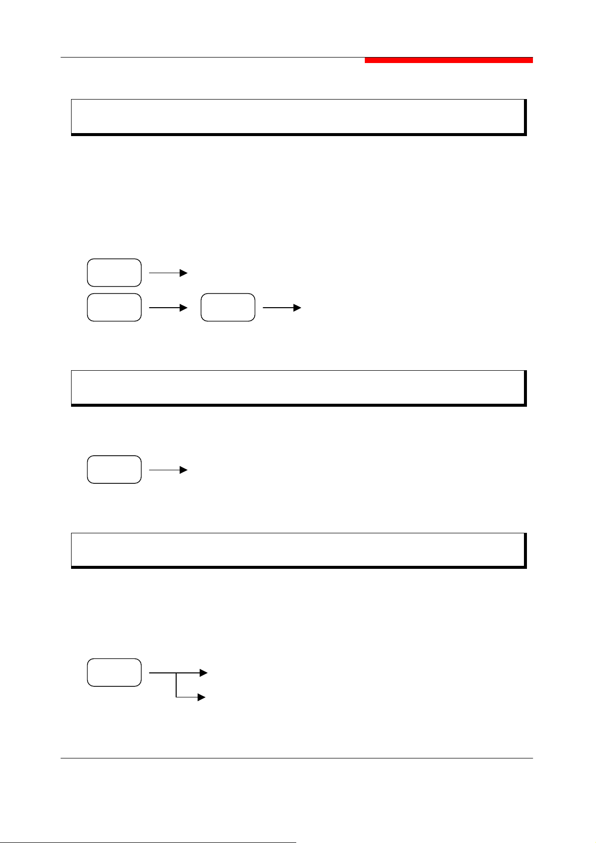
SECTION 5 OPERATING PROCEDURES
Setting Zero Span
This equipment can operate as a selective level meter in which the horizontal axis is
changed as a time axis by setting the frequency span to 0 ㎐.
The rising and falling edges of signal burst wave can also be observed and measured.
Performing any of the following key operations allows the equipment to operate in the zero
span mode.
SPAN Zero Span
SPAN 0 ㎐
Return to the Previous Span
The previous span is returned by the following key operation.
SPAN
Last Span
Zoom In/Zoom Out
The Zoom In function changes the span from the current span to 1/2 of the current span.
The Zoom Out function changes the span form the current span to 2 times the current span.
The center frequency is not changed.
SPAN
Zoom In
Zoom Out
5-11
Page 93

SECTION 5 OPERATING PROCEDURES
10 ㎒ Ref.
Set the reference clock for this equipment.
FREQ
Default setting is INT.
More.. 10 ㎒ Ref. [EXT / INT]
5-12
Page 94

SECTION 5 OPERATING PROCEDURES
A
A
AMPLITUDE FUNCTIONS
The AMPL key is used the header key for setting the amplitude.
Setting Reference Level
Set the reference level (top graticule) by performing the following key operations :
The step key size is the 1 division of current scale. (ref : Setting Amplitude Scale 5-14)
The scroll knob step size is 0.1 dB.
AMPL
Re f L e v e l
Nume r i c Ke y
Step key
Scroll knob
Selecting Log/Linear Detector Mode
To set the amplitude scale to log scale or linear scale, perform the following key operations :
(1) Setting log detector
(2) Setting linear detector
The reference level remains constant, independent of switching between log and linear.
MPL
MPL
Log
Linear
5-13
Page 95

SECTION 5 OPERATING PROCEDURES
A
V
V
V
V
A
Setting Amplitude Scale
In log scale, this equipment provides the four scales : 10dB/DIV, 5dB/DIV, 2dB/DIV, 1dB/DIV.
In linear scale, the equipment uses the Full Scale.
To select one of the scales, perform the following key operations :
Log Detector Mode
MPL
Scale
10dB/DI
5dB/DI
2dB/DI
1dB/DI
Prev..
Setting Amplitude Units
In log scale, this equipment provides the five types of reference level units : dBm, dBmV,
dBuV, VOLTS, WATTS.
To select on of the reference level units, perform the following key operations.
The reference level unit used for the linear scale is only in Volt.
MPL
Unit
dBm
dBmV
dBuV
VOLTS
WATTS
dBuV/m
Prev..
5-14
Page 96

SECTION 5 OPERATING PROCEDURES
A
Setting Input Attenuation
Perform the following key operation to set the input attenuator level.
AMPL
At ten.
[AUTO/MNL]
Nume r i c Key
The Atten. mode [AUTO or MNL] is changed by pressing the Atten key.
In Atten MNL (manual) mode, the step size can set by the numeric keys, step keys and scroll
knob. (Range 0 to 55 dB) (refer Input Attenuator at 5-40 page)
If Atten “AUTO” is selected, the input attenuator will be coupled by the current reference
level automatically.
Step key
Sc rol l kno b
Selecting Input Impedance
To select on of the input impedance, perform the following key operations.
Using
[75] is selected, this gives the method that user can use this equipment in such environment
as ignore reflection and calculate considering purely impedance matching.
MPL
Input Z
[ 50 / 75 ] menu, selecting input impedance 50 ohm or 75 ohm. When Input Z
More.. Input Z [ 50 / 75 ]
5-15
Page 97

SECTION 5 OPERATING PROCEDURES
A
Setting the Reference Level Offset
Set the reference level offset by performing the following key operations :
The reference level offset size is -217.6 dB to 297.6 dB.
AMPL
Ref. Offset
Num er i c Key
Setting Internal Amp
Set the internal amp to operate by performing the following key operations :
This function can use up to max 3GHz
Operate only in lower –20 dBm input signal level. Otherwise this
MPL
CAUTION
More.. Int Amp [OFF / ON]
equipment will damage.
Setting Calibration Signal Output
To set the calibration signal(20
5-16
AMPL
More.. Cal. Out[20M] [OFF/ ON]
㎒, -20dBm), perform the following key operations :
Page 98

SECTION 5 OPERATING PROCEDURES
MEASURMENT FUNCTIONS
The equipment provides the following measurement functions :
X dB Down Measurement
Adjacent Channel Power Measurement
Channel Power Measurement
Occupied Bandwidth Measurement
Harmonic Distortion Measurement
The measurement can be made in single or continuous sweep mode. Using Continuous
[OFF/ON] Softkey. Each measurement should close by press MEAS
Clear Measurement
.
X dB Down Measurement
The X dB Down function displays the difference in frequency between a reference marker
(◇ ) and another marker (→ ← ) that is X dB down from the reference.
The relative dB range that can be specified for X from the screen dynamic range is selected
using the step key or scroll knob. The default value is 3 dB.
To use the X dB Down measurement function, perform the following key operations :
MEAS
X [dB] Point
Start
Stop
XdB Down..
:
Place left and right markers at X dB down from the reference
marker.
:
When this key is pressed, X dB Down is executed continuously.
When Continuous off, one measurement executed.
(ref : Continue Measurement 5-21)
:
Stop X dB Down Measurement.
5-17
Page 99

SECTION 5 OPERATING PROCEDURES
Adjacent Channel Power Measurement
Determine the power in the center and adjacent channels of a signal (designated by three of
marker line).
MEAS
Adjacent CH Power..
MainChBW
AdjChBW
ChSpacing
Meas. Avg. [OFF / ON]
Start
Stop
Prev..
The measurement setup is done by numeric keys, step keys or scroll knob after pressed
each soft key. [
until warning or error message on the bottom of measurement clear. To get more stable
measurement value,
MainChBW, AdjChBW, ChSpacing
Meas Avg.
function can be set ON.
] These BW and spacing will be adjusted
Channel Power Measurement
Measure the power and power spectral density in the channel bandwidth specified by user.
MEAS
Channel Power..
Integ. BW
Ch PWR Span
MAX HOLD [OFF / ON]
Meas. Avg. [OFF / ON]
Start
Stop
Prev..
The measurement setup is done by numeric keys, step keys or Scroll knob after each soft
keys [
Integ BW, Ch PWR Span
message on the bottom of measurement clear. To get more stable measurement value,
function can be set ON.
The center frequency, reference level and channel bandwidth must be set by user.
5-18
]. These BW and spacing will be adjusted until warning or error
Meas Avg.
Page 100

SECTION 5 OPERATING PROCEDURES
Occupied Bandwidth Measurement
Locate the occupied bandwidth of the signal being displayed on the screen.
The results are shown in the marker display area for the occupied bandwidth (OBW), the
occupied band carrier frequency (Fc), and the band center frequency.
The equipment has an OBW function that can be calculated from the measurement data
displayed on the screen. It works by finding the frequency band that contains a specified
percentage of the total power. The default value is 98%, and measurement range between
5% and 100% can be specified.
OBW Measurement Procedure
(1) Set the center frequency & normal marker to the known carrier frequency and set the
frequency, span, resolution bandwidth (RBW), and sweep time to AUTO.
(2) Calculate the Occupied Bandwidth by performing the following key operations :
MEAS
Occupied
Bandwidth..
OBW Span
OBW %PWR
Start
Stop
(3) To change the ratio between the power contained in the occupied and the total power
first find the OBW, then use the numeric keys to set a new percentage. The band
markers will be adjusted automatically.
OBW Span is the same Span.
5-19
 Loading...