

Page 1
GF-128
OMM-0079_0B
INNOVATION Series
Gas-Fired Water Heaters
Installation, Operation, and Maintenance
Natural Gas Modulating,
Condensing Water Heater
Models:
• INN600
• INN800
• INN1060
Applicable to Serial Numbers
G-10-1350 to G-11-0563
Other documents for this product
include:
• GF-5030 INN Gas Supply Guide
• GF-5050 INN Venting Guide
• GF-5060 INN Elect. Power Guide
• GF-5080 INN Sizing Guide
Copies of these documents are
included in Appendices J thru M
of this Manual
Released: 07/21/2011
USER MANUAL
AERCO International, Inc. • 100 Oritani Dr. • Blauvelt, New York 10913 • Phone: 800-526-0288
Page 2

GF-128 Innovation Series Water He aters
Technical Support:
OMM-0079_0B USER MANUAL
(Mon–Fri, 8am-5pm EST)
1-800-526-0288
www.aerco.com
The information containe d in this manual is subject to c hange without notice from AERCO Inter national,
Inc. AERCO makes no warranty of any kind with respect to this material, including but not limited to
implied warranties of merchantability and fitness f or a particular application. AE RCO International is not
liable for errors appearing in this manual. Nor for incidental or consequential damages occurring in
connection with the furnishing, performance, or use of this material.
Page 2 of 200 AERCO International, Inc. • 100 Oritani Dr. • Blauvelt, NY 10913 • Ph.: 800-526-0288 07/21/11
Disclaimer
Page 3

Innovation Series Water Heaters GF-128
Table of Contents USER MANUAL OMM-0079_0B
TABLE OF CONTENTS
FOREWORD ................................................................................................................... 7
CHAPTER 1. SAFETY PRECAUTIONS .................................................................. 9
1.1 WARNINGS & CAUTIONS ................................................................................................. 9
1.2 EMERGENCY SHUTDOWN ............................................................................................. 10
1.3 PROLONGED SHUTDOWN ............................................................................................. 10
CHAPTER 2. INSTALLATION ............................................................................... 13
2.1 INTRODUCTION ............................................................................................................... 13
2.2 RECEIVING THE UNIT ..................................................................................................... 13
2.3 UNPACKING .................................................................................................................... 13
2.4 SITE PREPARATION ....................................................................................................... 13
2.4.1 Installation Clearances ..............................................................................................14
2.4.2 Setting the Unit ..........................................................................................................15
2.5 WATER INLET AND OUTLET PIPING ............................................................................. 15
2.6 TEST HOSE BIB CONNECTION ...................................................................................... 16
2.7 PRESSURE & TEMPERATURE RELIEF VALVE INSTALLATION .................................. 17
2.8 SYSTEM RECIRCULATION LOOP .................................................................................. 17
2.9 CONDENSATE DRAIN & PIPING .................................................................................... 17
2.10 GAS SUPPLY PIPING .................................................................................................... 19
2.10.1 Gas Supply Specifications. ........................................................................................20
2.10.2 Manual Gas Shutoff Valve .........................................................................................20
2.10.3 External Gas Supply Regulator ..................................................................................20
2.11 AC ELECTRICAL POWER WIRING ............................................................................... 21
2.11.1 Electrical Power Requirements ..................................................................................21
2.12 FIELD CONTROL WIRING ............................................................................................. 22
2.12.1 Outdoor Air Sensor ....................................................................................................23
2.12.2 AUX SENSOR IN ......................................................................................................23
2.12.3 ANALOG IN ...............................................................................................................23
2.12.4 B.M.S. (PWM) IN .......................................................................................................24
2.12.5 SHIELD .....................................................................................................................24
2.12.6 mA OUT ....................................................................................................................24
2.12.7 EXHAUST SENSOR IN .............................................................................................24
2.12.8 INTERLOCKS............................................................................................................24
2.12.9 FAULT RELAY ..........................................................................................................25
2.12.10 AUXILIARY RELAY CONTACTS.............................................................................25
2.13 FLUE GAS VENT INSTALLATION ................................................................................. 25
2.14 COMBUSTION AIR ......................................................................................................... 25
2.14.1 Combustion From Outside the Building .....................................................................26
2.14.2 Combustion Air from Inside the Building ....................................................................26
07/21/11 AERCO International, Inc. • 100 Oritani Dr. • Blauvelt, NY 10913 • Ph: 800-526-0288 Page 3 of 200
Page 4

GF-128 Innovation Series Water He aters
OMM-0079_0B USER MANUAL Table of Contents
2.15 SEALED COMBUSTION ................................................................................................. 26
CHAPTER 3. OPERATION .................................................................................... 27
3.1 INTRODUCTION ............................................................................................................... 27
3.2 CONTROL PANEL DESCRIPTION .................................................................................. 27
3.3 CONTROL PANEL MENUS .............................................................................................. 31
3.3.1 Menu Processing Procedure ......................................................................................31
3.4 OPERATING MENU ......................................................................................................... 32
3.5 SETUP MENU ................................................................................................................... 33
3.6 CONFIGURATION MENU ................................................................................................. 34
3.7 TUNING MENU ................................................................................................................. 35
3.8 START SEQUENCE ......................................................................................................... 36
3.9 START/STOP LEVELS ..................................................................................................... 38
CHAPTER 4. INITIAL START-UP ......................................................................... 41
4.1 INITIAL STAR T-UP REQUIREM ENTS ............................................................................. 41
4.2 TOOLS AND INSTRUMENTATION FOR COMBUSTION CALIBRATION ....................... 41
4.2.1 Required Tools & Instrumentation..............................................................................41
4.2.2 Installing Gas Supply Manometer ..............................................................................42
4.2.3 Accessing the Analyzer Probe Port ............................................................................42
4.3 NATURAL GAS COMBUST ION CALIBRATION .............................................................. 43
4.4 REASSEMBLY ................................................................................................................. 45
4.5 TEMPERATURE CONTROL CALIBRATION ................................................................... 45
4.5.1 Setting the Outlet Water Temperature Setpoint .........................................................45
4.5.2 Minimum Load Adjustment ........................................................................................46
4.5.3 Maximum Load Adjustment .......................................................................................46
4.6 OVER-TEMPERATURE LIMIT SWITCHES ...................................................................... 47
CHAPTER 5. SAFETY DEVICE TESTING ............................................................ 49
5.1 TESTING OF SAFETY DEVICES ..................................................................................... 49
5.2 LOW GAS PRESSURE FAULT TEST .............................................................................. 49
5.3 HIGH GAS PRESSURE TEST .......................................................................................... 50
5.4 LOW WATER LEVEL FAULT TEST ................................................................................. 50
5.5 WATER TEMPERATURE FAULT TEST .......................................................................... 51
5.6 INTERLOCK TESTS ......................................................................................................... 52
5.6.1 Remote Interlock .......................................................................................................52
5.6.2 Delayed Interlock .......................................................................................................53
5.7 FLAME FAULT TESTS ..................................................................................................... 53
5.8 AIR FLO W FAULT TESTS ............................................................................................... 54
Page 4 of 200 AERCO International, Inc. • 100 Oritani Dr. • Blauvelt, NY 10913 • Ph.: 800-526-0288 07/21/11
Page 5

Innovation Series Water Heaters GF-128
Table of Contents USER MANUAL OMM-0079_0B
5.9 SSOV PROOF OF CLOSURE SWITCH ........................................................................... 56
5.10 PURGE SWITCH OPEN DURING PURGE ..................................................................... 56
5.11 IGNITION SWITCH OPEN DURING IGNITION ............................................................... 57
5.12 SAFETY PRESSURE RELIEF VALVE TEST .................................................................. 58
CHAPTER 6. MAINTENANCE .............................................................................. 59
6.1 MAINTENANCE SCHEDULE ........................................................................................... 59
6.2 IGNITER-INJECTOR ........................................................................................................ 60
6.3 FLAME DETECTOR ......................................................................................................... 61
6.4 COMBUSTION CALIBRATION ........................................................................................ 62
6.5 SAFETY DEVICE TESTING ............................................................................................. 62
6.6 FIRESIDE INSPECTION ................................................................................................... 62
6.7 WATERSIDE INSPECTION .............................................................................................. 65
6.8 HEAT EXCHANGER CLEANING ..................................................................................... 67
6.8.1 Pumping System Set-Up Instructions ........................................................................67
6.8.2 Cleaning Procedure ...................................................................................................68
6.8.3 Testing HydroSkrub Effectiveness .............................................................................69
6.9 CONDENSATE DRAIN TRAP .......................................................................................... 69
6.10 AIR FILTER REPLACEMENT .......................................................................................... 70
6.11 SHUTTING THE WATER HEATER DOW N FO R AN EXTENDED PERI OD OF TIME ...... 71
6.12 PLACING THE HEATER BACK IN SERVICE AFTER A PROLONGED SHUTDOWN .... 71
CHAPTER 7. TROUBLESHOOTING GUIDE ........................................................ 73
7.1 INTRODUCTION ............................................................................................................... 73
7.2 ADDITIONAL FAULTS WITHOUT SPECIF IC FAULT MESSAGES ................................. 84
CHAPTER 8. RS232 COMMUNIC ATION .............................................................. 87
8.1 INTRODUCTION ............................................................................................................... 87
8.2 RS232 COMMUNICATION SETUP .................................................................................. 87
8.3 MENU PROCESSING UTILIZING RS232 COMMUNI CATION ......................................... 87
8.4 DATA LOGGING .............................................................................................................. 88
8.4.1 Fault Log ...................................................................................................................88
8.4.2 Operation Time Log ...................................................................................................89
8.4.3 Sensor Log ................................................................................................................89
07/21/11 AERCO International, Inc. • 100 Oritani Dr. • Blauvelt, NY 10913 • Ph: 800-526-0288 Page 5 of 200
Page 6

GF-128 Innovation Series Water He aters
OMM-0079_0B USER MANUAL Table of Contents
APPENDIX A: WATER HEATER MENU ITEM DESCRIPTIONS ............................... 91
APPENDIX B: STARTUP, STATUS AND FAULT MESSAGES ................................. 95
APPENDIX C 99TEMPERATURE SENSOR RESISTANCE/VOLTAGE CHART ........ 99
APPENDIX D: WATER HEATER DEFAULT SETTINGS .......................................... 101
APPENDIX E: PARTS LIST DRAWINGS .................................................................. 103
APPENDIX F: PIPING DRAWINGS ........................................................................... 113
APPENDIX G: C-MORE CONTROL PANEL VIEWS ................................................ 127
APPENDIX H: C-MORE WIRING DIAGRAMS .......................................................... 129
APPENDIX I: RECOMMENDED SPARES ................................................................ 137
APPENDIX J: GF-5030: GAS COMPONENTS & SUPPLY DESIGN GUIDE .......... 139
APPENDIX K: GF-5050: VENTING & COMBUSTION AIR GUIDE ......................... 151
APPENDIX L: GF-5060: ELECTRICAL POWER GUIDE ......................................... 175
APPENDIX M: GF-5080: COMMERCIAL LAUNDRY SIZING GUIDE ..................... 183
APPENDIX N: LIMITED WARRANTY ....................................................................... 195
Page 6 of 200 AERCO International, Inc. • 100 Oritani Dr. • Blauvelt, NY 10913 • Ph.: 800-526-0288 07/21/11
Page 7

Innovation Series Water Heaters GF-128
Foreword USER MANUAL OMM-0079_0B
FOREWORD
The AERCO Innovation Series Water Heaters are modulating units which represent a true
industry advance that meets the needs of today's energy efficiency and environmental
concerns. Designed for use in any domestic water heating system, each Innovation model
provides precisely-controlled potable water within ±2°F of setpoint, regardless of flow rate.
Innovation’s compact size and varied venting capabilities allow maximum installation flexibility.
The Innovation Series Heaters, with their load tracking controls modulate over a 20:1 turn down
ratio to match the system demand and yield high thermal efficiencies.
When installed and operated on natural gas in accordance with this Instruction Manual, the
Innovation Series Models covered herein comply with the NOx emission standards outlined in:
• South Coast Air Quality Management District (SCAQMD), Rule 1146.2
• Texas Commission on Environmental Quality (TCEQ), Title 30, Chapter 117,
Rule 117.465
Whether used in singular or modular arrangements, the Innovation Heaters offer the maximum
flexibility in venting with minimum installation space requirements. Innovation’s advanced
electronic controls offer simplified integration with today’s Energy Management Systems.
For service or parts, contact your local sales representative or AERCO INTERNATIONAL.
NAME:
ORGANIZATION:
ADDRESS:
TELEPHONE:
INST ALLATION DATE: ___________________________________________________
07/21/11 AERCO International, Inc. • 100 Oritani Dr. • Blauvelt, NY 10913 • Ph: 800-526-0288 Page 7 of 200
Page 8

GF-128 Innovation Series Water He aters
OMM-0079_0B USER MANUAL Foreword
This P age Is Intentionally Blank
Page 8 of 200 AERCO International, Inc. • 100 Oritani Dr. • Blauvelt, NY 10913 • Ph.: 800-526-0288 07/21/11
Page 9

Chapter 1 Innovation Series Water He ate rs GF-128
Safety Precautions USER MANUAL OMM-0079_0B
CHAPTER 1. SAFETY PRECAUTIONS
1.1 WARNINGS & CAUTIONS
Installers and operating personnel MUST, at all times, observe all safety regulations. The following
warnings and cautions are gener al and m ust be given the same attention as spec ific precautio ns included
in these instructions. In addition to all the requirements inc luded in this AERCO Instruction Manu al, the
installation of units MUST conform with local building codes, or, in the absence of local codes, ANSI
Z223.1 (National Fuel G as C ode Pub lica tio n No. NFPA-54) for gas-fired heaters and ANSI/ NFP AS B f or LP
gas-fired heaters. Where applicable, the equipment shall be installed in accordance with the current
Installation Code for Gas Burning Appliances and Equipment, CSA B149.1, and applicable Provincial
regulations for the class; which should be carefully followed in all cases. Authorities having jurisdiction
should be consulted before installations are made.
See pages 11 and 1 2 for important inf ormation re garding installation of units wit hin the Com monwealth of
Massachusetts.
IMPORTANT
This Instruction Manual is an integral part of the product and must be maintained
in legible condition. It must be given to the user by the installer and kept in a safe
place for future reference.
IMPORTANT
Read the following restrictions prior to installing the water heater:
1. The water heater can only be used for applications where the chlorine
concentrations Do Not Exceed 4 mg/L which is the Environmental Protection
Agency limit for chlorine concentrations in drinking water.
2. Do Not use this heater for a pool heating application.
WARNING
DO NOT USE MATCHES, CANDLES, FLAMES, OR OTHER SOURCES OF
IGNITION TO CHECK FOR GAS LEAKS.
WARNING
FLUIDS UNDER PRESSURE MAY CAUSE INJURY TO PERSONNEL OR
DAMAGE TO EQUIPMENT WHEN RELEASED. BE SURE TO SHUT OFF ALL
INCOMING AND OUTGOING WATER SHUTOFF VALVES. CAREFULLY
DECREASE ALL TRAPPED PRESSURES TO ZERO BEFORE PERFORMING
MAINTENANCE.
WARNING
ELECTRICAL VOLTAGES UP TO 120 VAC MAY BE USED IN THIS
EQUIPMENT. THEREFORE THE COVER ON THE UNIT’S POWER BOX
(LOCATED BEHIND THE FRONT PANEL DOOR) MUST BE INST ALL ED AT ALL
TIMES, EXCEPT DURING MAINT E NANCE AND SE RVICING.
WARNING
A DOUBLE-POLE SWITCH MUST BE INSTALLED ON THE ELECTRICAL
SUPPLY LINE OF THE UNIT. THE SWITCH MUST BE INSTALLED IN AN
EASILY ACCESSIBLE POSITION TO QUICKLY AND SAFELY DISCONNECT
ELECTRICAL SERVICE. DO NOT AFFIX SWITCH TO UNIT SHEET METAL
ENCLOSURES.
07/21/11 AERCO International, Inc. • 100 Oritani Dr. • Blauvelt, NY 10913 • Ph: 800-526-0288 Page 9 of 200
Page 10
GF-128 Innovation Series Water He aters Chapter 1
MANUAL GAS SHUTOFF VALVE
VALVE OPEN
VALVE CLOSED
OMM-0079_0B USER MANUAL Safety Precautions
CAUTIONS
Must be observed to prevent equipment damage or loss of operating
effectiveness.
CAUTION
Many soaps used for gas pipe leak testing are corrosive to metals. The piping
must
completed.
DO NOT use this heater if any part has been under water. Call a qualified service
technician to inspect and replace any part that has been under water.
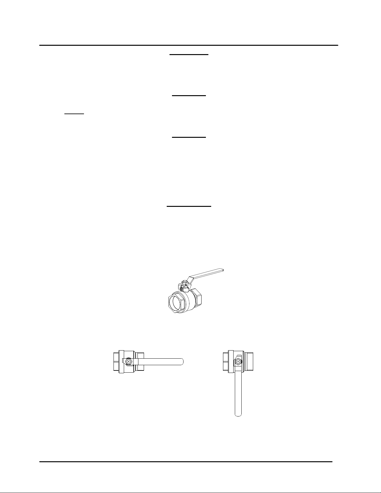
1.2 EM ERGENCY SHUTDOWN
If overheati ng occurs or the gas suppl y fails to shut of f, close the manual gas shutof f valve (Figure 1-1)
located external to the unit.
The Installer mus t identify and indicate the locat ion of the emergency shutdo wn manual
gas valve to operating personnel.
be rinsed thoroughly with clean water after leak checks have been
CAUTION
IMPORTANT
1.3 PRO L ONGED SHUTDOWN
After prolonged shutdown, it is recommended that the startup procedures in Chapter 4 and the safety
device test procedures in Chapter 6 of this manual be performed, to verify all system-operating
parameters. If ther e is an em ergency, turn of f the ele ctrical power suppl y to the AERC O heater and close
the manual gas valve located upstream the unit. The installer must identify the emergency shut-off device.
Page 10 of 200 AERCO International, Inc. • 100 Oritani Dr. • Blauvelt, NY 10913 • Ph.: 800-526-0288 07/21/11
Figure 1-1. Manual Gas Shutoff Valve
Page 11

Chapter 1 Innovation Series Water He ate rs GF-128
Safety Precautions USER MANUAL OMM-0079_0B
IMPORTANT – FOR MASSACHUSETTS I NSTALLATIONS
Water heater Installations within the Commonwealth of Massachusetts must
conform to the following requirements:
• Heater must be installed by a plumber or a gas fitter who is licensed within the
Commonwealth of Massachusetts.
• Prior to unit operation, the complete gas train and all connections must be leak
tested using a non-corrosive soap.
• The vent termination must be located a minimum of 4 feet above grade level.
If side-wall venting is used, the installation must conform to the following
requirements extracted from 248 CMR 5.08 (2):
(a) For all side wall horizontally vented gas fueled equipment installed in every dwelling, building or
structure used in whole or in part for residential purposes, including those owned or operated by the
Commonwealth and where the side wall exhaust vent termination is less than seven (7) feet above finished
grade in the are a of the ventin g, inclu ding b ut not l im ited to deck s and porches , the f ollo wing requir em ents
shall be satisfied:
1. INSTALLAT ION OF CARBON MONOXID E DETECTORS
horizontal vented gas f ueled equipment, the installing plum ber or gasfitter sha ll observe that a har d wired
carbon monoxide detector with an alarm and battery back-up is installe d on the floor level where the gas
equipment is to be installed. In addition, the installing plumber or gasfitter shall observe that a battery
operated or hard wired car bon monox ide detec tor w ith an alar m is ins talled on each ad ditiona l level of the
dwelling, building or s tructure served by the sid e wall horizontal vented g as fueled equipment. It s hall be
the responsibility of the pr operty owner to secure the services of qual ified licensed professionals for the
installation of hard wired carbon monoxide detectors.
a. In the event that the side wall horizontally vented gas f ueled equipment is installed in a crawl
space or an attic, the har d wired carbon monoxide d etector with alarm and batter y back-up may be
installed on the next adjacent floor level.
b. In the event that the re quirements of this subdivision can not b e met at the tim e of completion of
installation, the owner shall have a period of thirt y (30) da ys to compl y with the abov e requirem ents;
provided, however, that during said thirty (30) day period, a battery operated carbon monoxide
detector with an alarm shall be installed.
2. APPROVED CARBON MONOXIDE DETECTORS.
accordance with the a bove provisions sha ll comply with NFPA 72 0 and be ANSI/UL 2034 listed and IAS
certified.
3. SIGNAGE
building at a minim um height of eight (8) f eet abo ve grade d irectl y in line with the exhaus t vent t erm inal for
the horizontally vented gas fueled heating appliance or equipment. The sign shall read, in print size no less
than one-half (1/2) inch in size, "GAS VENT DIRECTLY BELOW. KEEP CLEAR OF ALL
OBSTRUCTIONS".
. A metal or plastic identif ication plate shall be permanently mount ed to the exterior of the
. At the time of installation of the side wall
Each carbon monoxide detector as required in
4. INSPECTION
equipment shall not approve the installation unless, upon inspection, the inspector observes carbon
monoxide detectors and signage installed in accordance with the provisions of 248 CMR 5.08(2)(a)1
through 4.
07/21/11 AERCO International, Inc. • 100 Oritani Dr. • Blauvelt, NY 10913 • Ph: 800-526-0288 Page 11 of 200
. The state or local gas inspector of the side wall horizontally vented gas fueled
Page 12

GF-128 Innovation Series Water He aters Chapter 1
OMM-0079_0B USER MANUAL Safety Precautions
(b) EXEMPTIONS
1. The equipment listed in Chapter 10 ent itled "Equipm ent Not Required To Be Vented" in the m ost
current edition of NFPA 54 as adopted by the Board; and
2. Product Approved side wall horizontally vented gas fueled equipment installed in a room or
structure separate from the dwelling, building or structure used in whole or in part for residential
purposes.
(c) MANUFACTURER REQUIREMENTS - GAS EQUIPMENT VEN TING SYSTE M PROVIDED.
manufacturer of Produc t Approved side wall horizonta lly vented gas eq uipment provi des a venting system
design or venting s ystem components with the equipm ent, the instructions provided b y the manufacturer
for installation of the equipment and the venting system shall include:
1. Detailed instructions for the installation of the venting system design or the venting system
components; and
2. A complete parts list for the venting system design or venting system.
(d) MANUFACTURER REQUIREMENTS - GAS EQUIPMENT VENTING SYSTEM NOT PROVIDED.
When the manufact urer of a Product Approved si de wall horizontally vented ga s fueled equipment does
not provide the parts for venting the flue gases, but identifies "special venting systems", the following
requirements shall be satisfied by the manufacturer:
1. The referenced "special venting system" instructions shall be included with the appliance or
equipment installation instructions; and
: The following equipment is exempt from 248 CMR 5.08(2)(a)1 through 4:
When the
2. The "special vent in g s ys tems" shall be Product Ap p roved by the Board, and the ins truc t ions f or th at
system shall include a parts list and detailed installation instructions.
(e) A copy of all ins tallation instr uctions for all Pr oduct Approved s ide wall horiz ontally vented g as fueled
equipment, all venting instructions, all parts lists for venting instructions, and/or all venting design
instructions shall remain with the appliance or equipment at the completion of the installation.
______________________________________
[End of Extracted Information From 248 CMR 5.08 (2)]
Page 12 of 200 AERCO International, Inc. • 100 Oritani Dr. • Blauvelt, NY 10913 • Ph.: 800-526-0288 07/21/11
Page 13

Chapter 2 Innovation Series Water Heater s GF-128
Installation USER MANUAL OMM-0079_0B
CHAPTER 2. INSTALLATION
2.1 INTRODUCTION
This Chapter provides the descriptions and proc edures necess ary to unpack, inspec t and install AERCO
Innovation Water Heater Models INN 600, INN 800 and INN 1060.
2.2 RECEIVING THE UNIT
Each Innovation Water Heating System is shipped as a single crated unit. The shipping weight is
approximately 1200 pounds. The unit m ust be moved with the proper rigg ing equipment f or safety and to
avoid equipment dam age. T he unit should b e com pletely inspected f or evidenc e of s hipping dam age and
shipment completeness at the time of receipt from the carrier and before
NOTE
AERCO is not responsible for lost or damaged freight. Each unit has a Tip-N-Tell
indicator on the outside of the crate. This indicates if the unit has been turned on
its side during shipment. If the Tip-N-Tell indicator is tripped, do not sign for the
shipment. Note the information on the carrier’s paperwork and request a freight
claim and inspection by a claims adjuster before proceeding. Any other visual
damage to the packaging mater ials should also be made clear to the delivering
carrier.
the bill of lading is signed.
2.3 UNPACKING
Carefully unpack the unit taking care not to damage the unit enclosure when cutting away packaging
materials
After unpacking, a close inspection of the unit sh ould be made to ensure that there is no evidence of
damage not indicated b y the Tip-N-T ell indicator. The f reight carrier shou ld be notified imm ediately if an y
damage is detected.
The following access ories come standard with each un it and ar e e ith er packed separately within the unit’s
shipping container or are factory installed on the unit:
• Pressure/Temperature Gauge
• Spare Spark Igniter-Injector
• Spare Flame Detector
• ASME Pressure Relief Valve
• Condensate Drain Trap
• 1-1/2” Gas Supply Shutoff Valve
When optional access ories are order ed, they may be pack ed within the unit ’s shipping container , factory
installed on the unit, or pac ked and shipped in a separate c onta in er . Any standard or optional acces s ories
shipped loose should be identified and stored in a safe place until ready for installation or use.
2.4 SITE PREPARATION
Ensure that the site selected for installation of the Innovation Water Heater includes:
• Access to AC Input Power at 120 VAC, Single-Phase, 60 Hz @ 20 Amps.
• Access to Natural Gas line at a minimum pressure of 4 inches W.C.
07/21/11 AERCO International, Inc. • 100 Oritani Dr. • Blauvelt, NY 10913 • Ph: 800-526-0288 Page 13 of 200
Page 14
GF-128 Innovation Series Water He aters Chapter 2
OMM-0079_0B USER MANUAL Installation
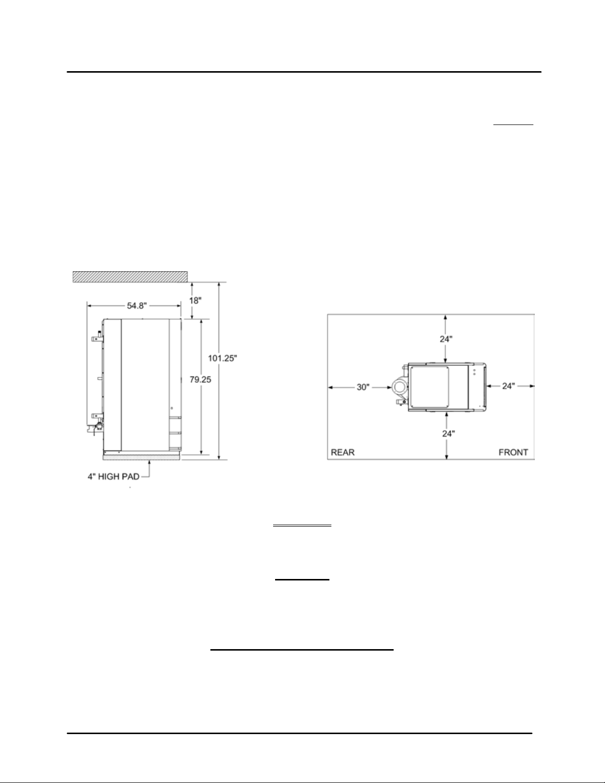
2.4.1 Installation Clearances
Innovation Models 790 and 1060 are packaged in enclosur es having identical exterior dim ensions. The
unit must be installed with the prescribed clearances for service as shown in Figure 2-1. The minimum
clearance dimens ions, required by AERCO, are liste d below. However, if Local Building Codes require
additional clearances, these codes shall supersede AERCO’s requirements. Minimum acceptable
clearances required are as follows:
• Sides: 24 inches
• Front : 24 inches
• Rear: 30 inches
• Top: 18 inches
All gas piping, water pi ping and electric al conduit or c able must be ar ranged so that th ey do not interf ere
with the removal of any panels, or inhibit service or maintenance of the unit.
Figure 2-1 Innovation Water Heater Clearances
WARNING
KEEP THE UNIT AREA CLEAR AND FREE FROM ALL COMBUSTIBLE
MATERIALS AND FLAMMABLE VAPORS OR LIQUIDS
.
CAUTION
While packaged in the shipping container, the unit must be moved by pallet jack
or forklift from the FRONT ONLY.
FOR MASSACHUSSETTS ONLY:
For Massachusetts installations, the unit must be installed by a plumber or gasfitter who is licensed within the Commonwealth of Massachusetts. In addition, the
installation must comply with all requirements specified in Chapter 1 (Safety
Precautions), pages 11 and 12.
Page 14 of 200 AERCO International, Inc. • 100 Oritani Dr. • Blauvelt, NY 10913 • Ph.: 800-526-0288 07/21/11
Page 15
Chapter 2 Innovation Series Water Heater s GF-128
Installation USER MANUAL OMM-0079_0B
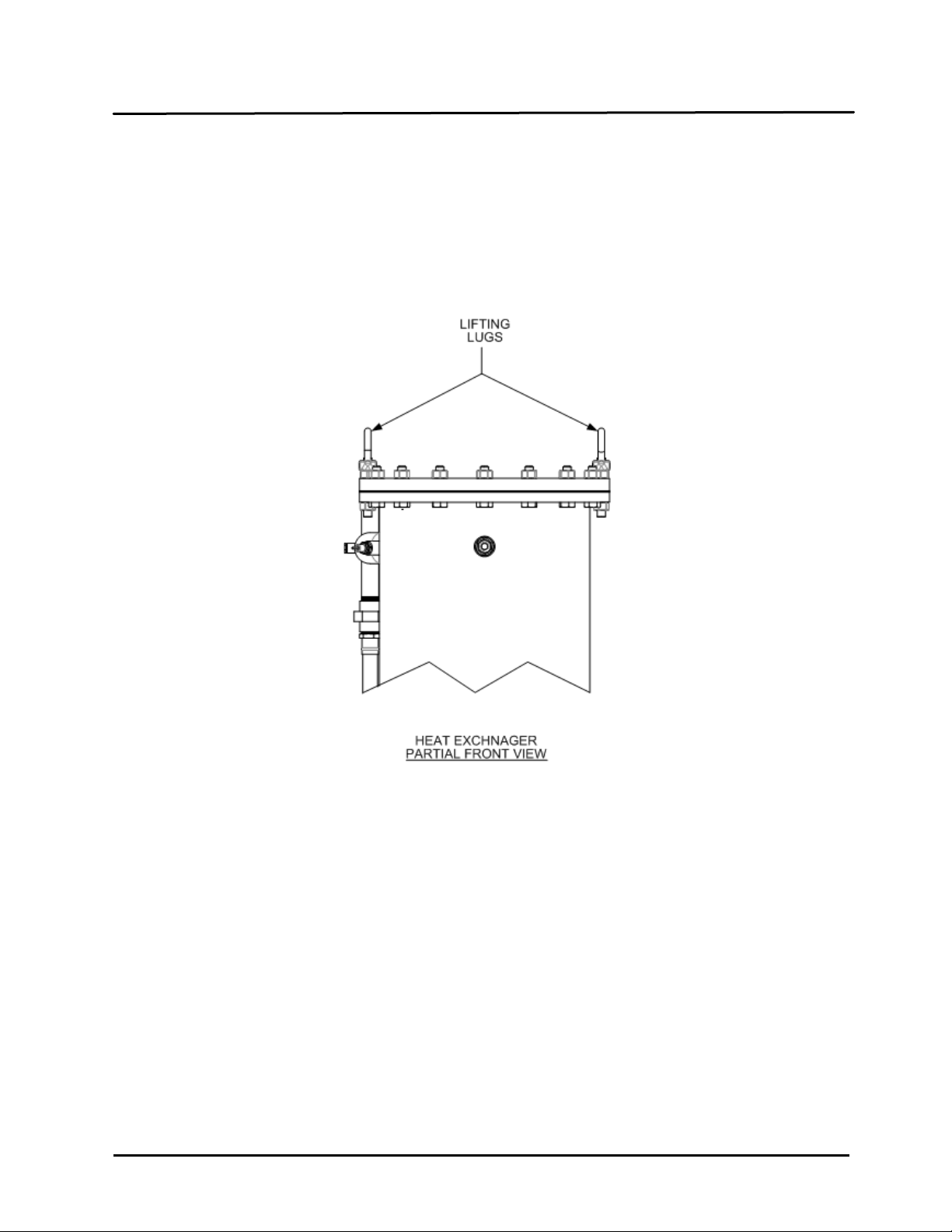
2.4.2 Setting the Unit
The unit must be instal le d on a 4 inch to 6 inch h ous e k eeping p ad t o ensure proper condensate drainage.
If anchoring the unit, r ef er to the dimensional drawings in Appendix F f or anc hor l ocatio ns. Two lifting lugs
are provided at the top of the heat exchan ger as sho wn in Figure 2-2. USE THESE TWO LUGS T O LIFT
AND MOVE THE UNIT. Rem ove the top pane l from the unit to provide acc ess to the lif ting lugs. Rem ove
the four (4) lag screws s ecuring the unit to the s h ipp ing s kid. Lift the unit off the s hip ping s kid and position
it on the 4 inch to 6 inch housekeeping concrete pad (required) in the desired location.
Figure 2-2
Partial Top View Showing Lifting Tab Location
In multiple unit installations , it is im por tant to plan the position of each unit in advance. Sufficient space for
piping connections and fut ure service/maintenance requirem ents must also be taken into consideration.
All piping must include ample provisions for expansion.
2.5 WATER INLET AND OUTLET PIPING
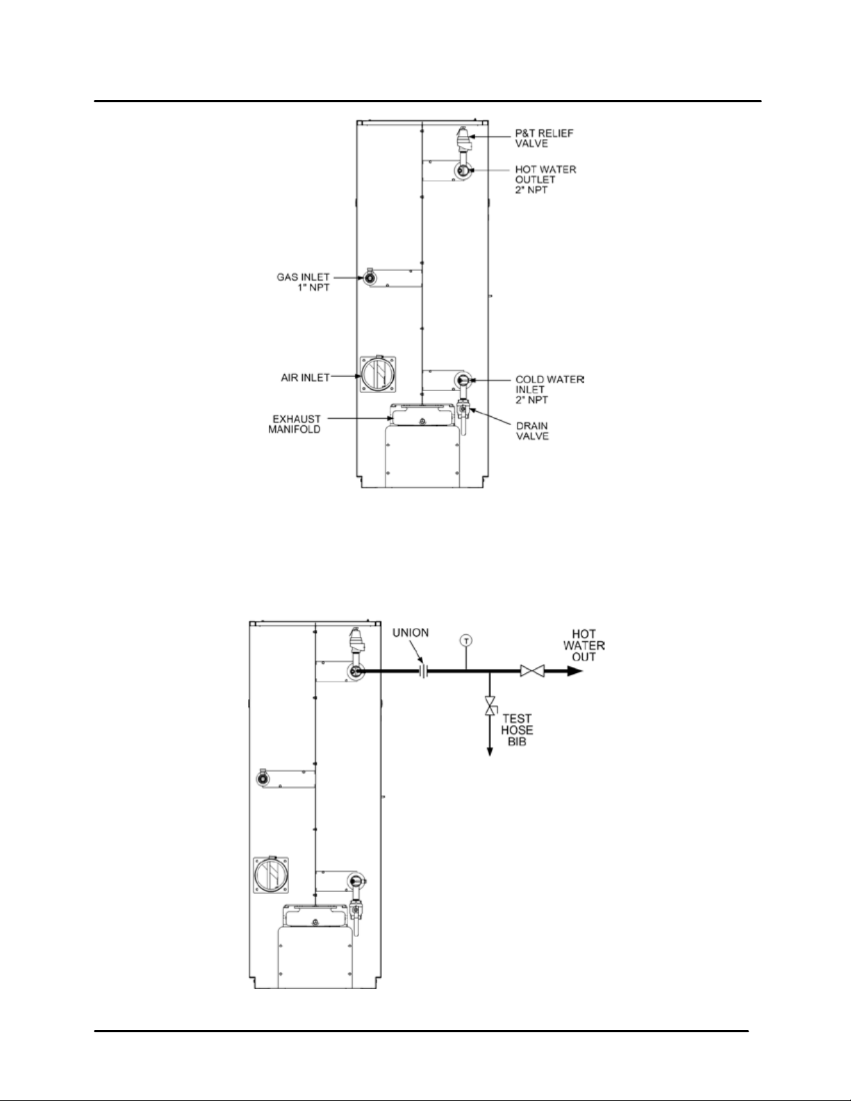
The locations of the 2" NPT cold water inlet and hot water outlet p iping connections ar e shown in Figure
2-3. Flow rates through the unit are limited to 30 gpm continuous and 40 gpm intermittent.
Shut-off valves and union connections must be installed in the inlet and outlet lines for
maintenance. The use of dielectric unions is recommended.
NOTE:
All piping must be arranged so that it does not interfere with removal of any covers, inhibit
service or maintenance, or prevent access between the unit and walls, or another unit.
07/21/11 AERCO International, Inc. • 100 Oritani Dr. • Blauvelt, NY 10913 • Ph: 800-526-0288 Page 15 of 200
Page 16
GF-128 Innovation Series Water He aters Chapter 2
OMM-0079_0B USER MANUAL Installation
Figure 2-3. Water Inlet & Outlet Locations
2.6 TEST HOS E BIB CONNECTION
A Test Hose Bib connecti on, upstream of the s hut off valve on the hot water out let, is requir ed for star tup
and testing (Figure 2-4) . The pipe d iameter should be a m inimum of 3/4". The Test Hose Bib cannot be
omitted.
Figure 2-4. Test Hose Bib Location
Page 16 of 200 AERCO International, Inc. • 100 Oritani Dr. • Blauvelt, NY 10913 • Ph.: 800-526-0288 07/21/11
Page 17
Chapter 2 Innovation Series Water Heater s GF-128
Installation USER MANUAL OMM-0079_0B
NOTE:
The maximum working pre ssure f or installations within t he Province of Alberta is 87 psig.
Therefore, a pressure & temperature relief valve with a setting of 75 psig/210°F is
supplied with Alberta shipments. See Drawing AP-A-863 in Appendix E.
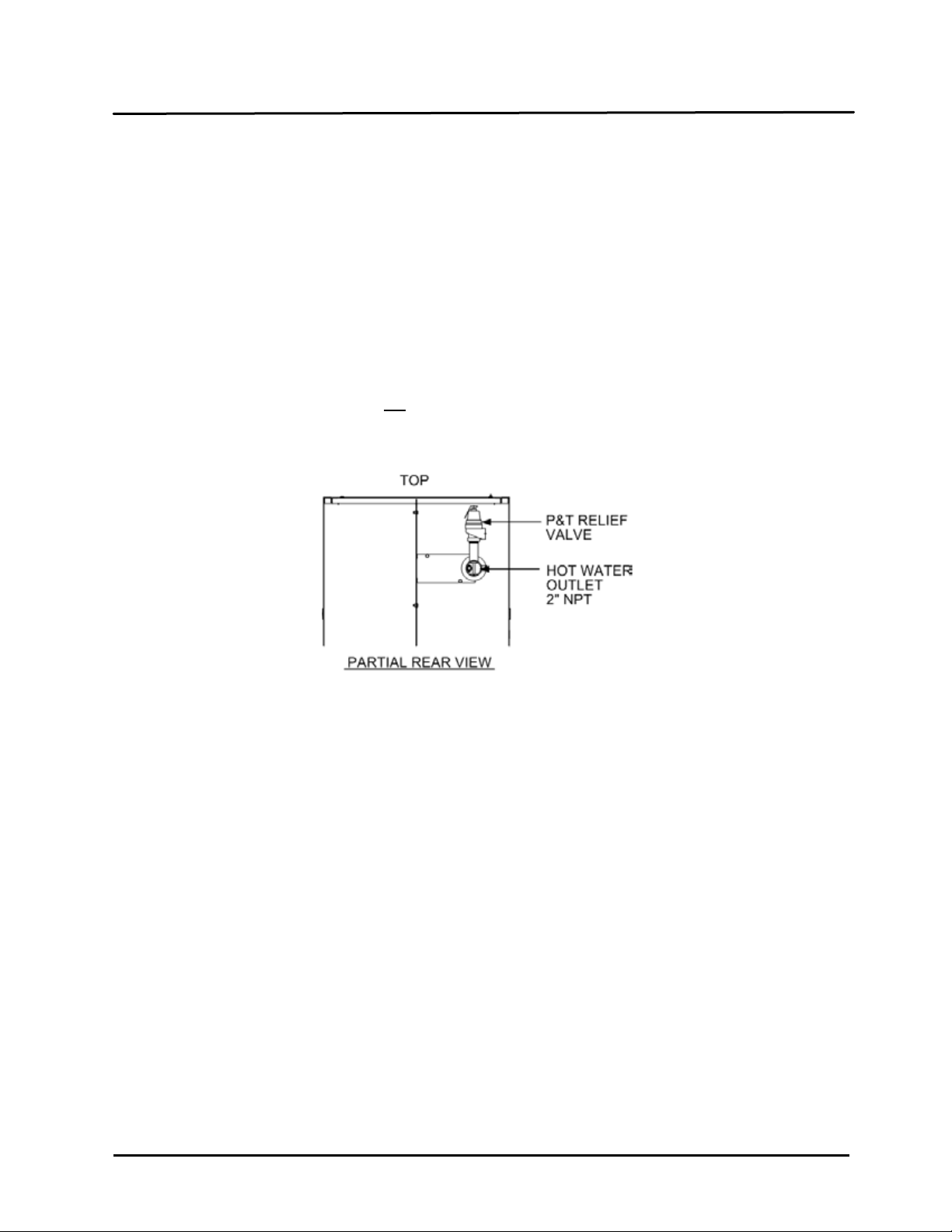
2.7 PRESSURE & TEMPERATURE RELIEF VALVE INSTALLATION
An ASME rated Pressure & Temperature (P&T) Relief Valve is supplied with each Innovation Water
Heater. With the exc eption of Alberta insta llations (see above Note) , the v alve s etpoi nt is 150 psi g/210°F.
The P&T Relief V al ve is installed at the to p of th e R ec i r culati on Loo p As sembly as shown in F i gure 2-5. A
suitable pipe joint com pound should be used on the threaded c onnections. Any excess should be wiped
off to avoid getting an y into the valve body. The reli ef valve should be piped to within 12 inches of the
floor to prevent injury in the event of a discharge. The relief piping must be full size, 1-1/2”, without
reduction. No valves , restrictions, or other blockages are allowed in the discharge line. In m ultiple unit
installations the discharge lines must not
suitable discharge location.
be manifolded together. Each must be individually run to a
Figure 2-5. P&T Relief Valve Location
2.8 SYSTEM RECIRCULATION LOOP
The System Recirculati on Loop Assembly is located at the rear of the unit as shown in Fi gure 2-5. This
assembly contains a rec irculator pum p which c on nec t s bet ween the upper hot wat er o utl et and l o wer c o ld
water inlet of the unit’s heat exchanger. The purpose of this loop is to provide feed-forward (FFWD)
temperature control by mixing a portion of the hot water outlet with the cold water inlet of the unit.
Temperature sensors located in the hot water outlet and c old water inlet provide temperatur e data to t he
C-More Control System . The Control System utilizes this data to m odulate the fire rate (Air/Fuel Valve
position) to precisely maintain the hot water outlet temperature at the selected setpoint temperature.
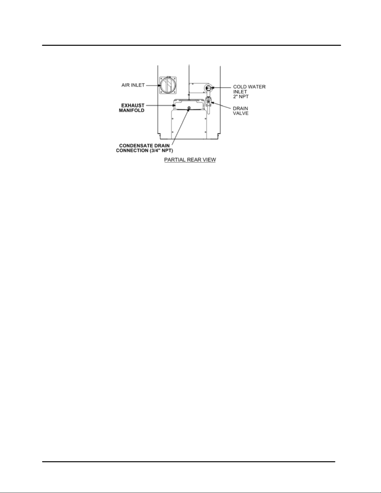
2.9 CONDENSATE DRAIN & PIPING
The Innovation Water Heater is des igned t o condens e wat er vapor f rom the flue produc ts. T heref ore, the
installation must have provisions for suitable condensate drainage or collection.
The condensate drai n port, is located on the exhaust manifold at the rear of the unit (Figure 2-6). This
drain port must be connected t o the C ondensate T rap (part n o. 240 60) which is pack ed separate ly with in
the unit’s shipping conta iner. The Condensat e Trap inlet and o utlet connectio ns contain tappe d 3/4” NPT
ports.
07/21/11 AERCO International, Inc. • 100 Oritani Dr. • Blauvelt, NY 10913 • Ph: 800-526-0288 Page 17 of 200
Page 18
GF-128 Innovation Series Water He aters Chapter 2
OMM-0079_0B USER MANUAL Installation
Figure 2-6. Condensate Drain Connection Location
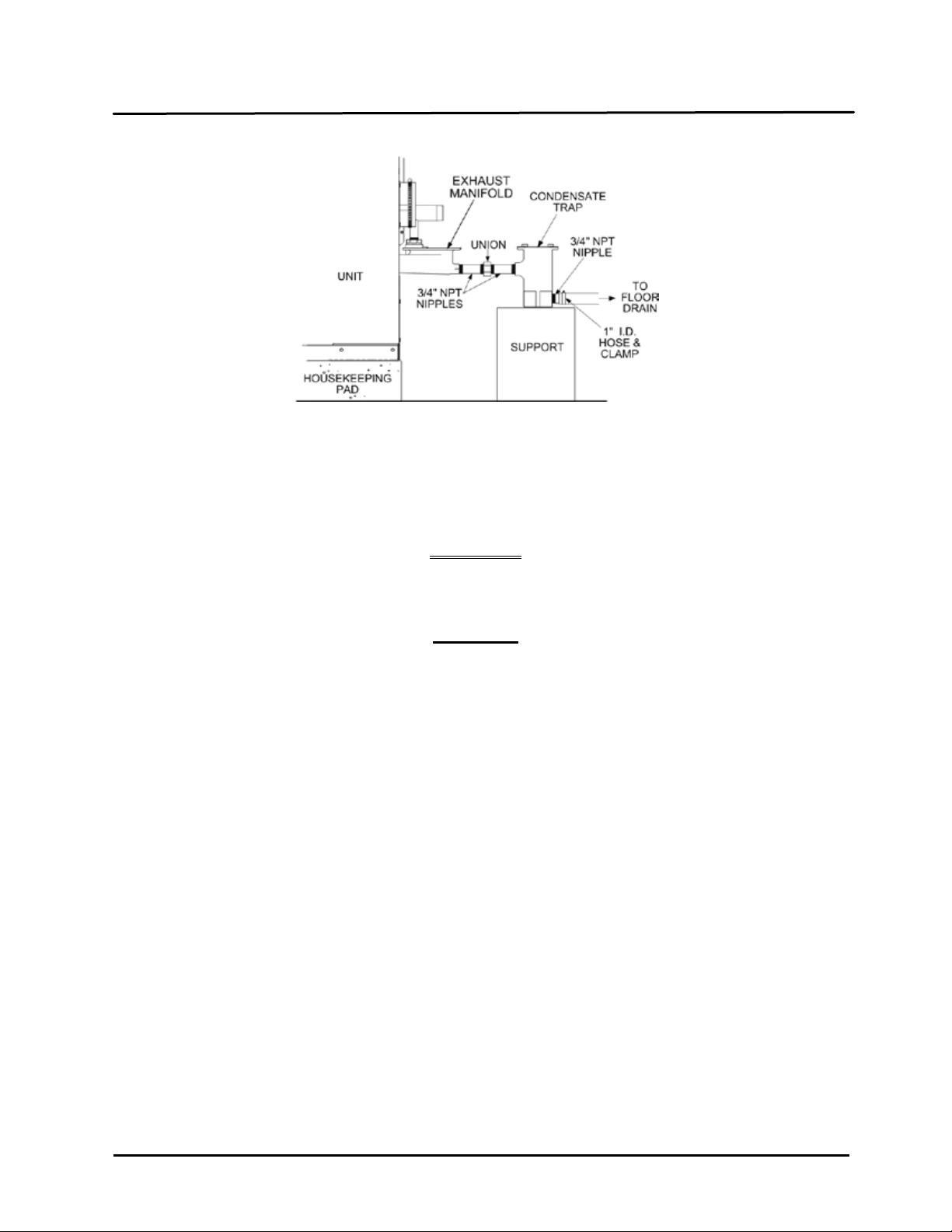
A sample Condensate T rap inst allation is shown in Figure 2-7. However, the actual insta llation details f or
the trap will var y depend ing on the avai lable c learanc es , housek eepin g pad heig ht/ dim ens ions and other
prevailing conditions at the site. the following general guidelines must be observed to ensure proper
condensate drainage:
• The condensate trap inl et (Figure 2-6) must be level with, or lower than the exhaust m anifold drain
port.
• The base of the condensate trap must be supported to ensure that it is level (horizontal).
• The trap must be rem ovable for routine maintenance. AERCO rec ommends that a union be utilized
between the exhaust manifold condensate drain port and the trap inlet port.
While observing the above guidelines, install the condensate trap as follows,
1. Connect the condensate trap inlet to the exhaust manifold drain connection using the appropriate
piping components (nipples, reducers, elbows, etc.) for the heater installation site.
2. At the condensate trap outlet, install a 3/4” NPT nipple.
3. Connect a length of 1” I.D polypropylene hose to the trap outlet and secure with a hose clamp.
4. Route the hose on the trap outlet to a nearby floor drain.
If a floor drain is not a vailable, a condens ate pum p can be used to rem ove the c ondensate to drain . The
maximum condensate flow rate is 20 G PH. The condensate drain trap, associat ed fittings and dra in line
must be removable for routine maintenance.
Page 18 of 200 AERCO International, Inc. • 100 Oritani Dr. • Blauvelt, NY 10913 • Ph.: 800-526-0288 07/21/11
Page 19
Chapter 2 Innovation Series Water Heater s GF-128
Installation USER MANUAL OMM-0079_0B
Figure 2-7. Sample Condensate Trap Installation
2.10 GAS SUPPLY PIPING
The AERCO Innovat ion Gas Com ponents and S upply Design Gu ide, GF-5030 (see Append ix J) must be
consulted prior to designing or installing any gas supply piping.
WARNING
NEVER USE MATCHES, CANDLES, FLAMES OR OTHER SOURCES OF
IGNITION TO CHECK FOR GAS LEAKS
.
CAUTION
Many soaps used for gas pipe leak testing are corrosive to metals. Therefore,
piping must be rinsed thoroughly with clean water after leak checks have been
completed.
All gas piping must be arranged so that it does not interfere with removal of any
covers, inhibit service/maintenance, or restrict access between the unit and
walls, or another unit.
Innovation units contain a 1 inch NPT gas inlet connection on the rear of the unit as shown in Figure 2-3.
NOTE
Prior to installation, all pip es should be d e-bur red an d inter nall y clear ed of an y scale, m etal ch ips or ot her
foreign particles. Do Not install any flexible connectors or unapproved gas fittings. Piping must be
supported from the floor, ceiling or walls only and must not be supported by the unit.
A suitable piping com pound, approved for use with natural gas, should be used. Any excess must be
wiped off to prevent clogging of components.
To avoid unit damage when pres s ure t esti ng gas p ip in g, isol ate t he u nit f r om the gas supply piping. A t no
time should the gas press u re applied to the unit exceed 14” W.C.. Leak tes t all e xter nal p ip ing thor o ugh ly
using a soap and water s olution or suitable equivalent. The gas piping used must meet all appl icable
codes.
07/21/11 AERCO International, Inc. • 100 Oritani Dr. • Blauvelt, NY 10913 • Ph: 800-526-0288 Page 19 of 200
Page 20
GF-128 Innovation Series Water He aters Chapter 2
OMM-0079_0B USER MANUAL Installation
2.10.1 Gas Supply Specifications.
The gas supply input specifications to the unit for Natural Gas are as follows:
The maximum static pressure to the unit mus t not exceed 14” W .C. The gas supply pressur e to the unit
must be of suff icient capaci ty to pro vide 1060 cfh while m aintain ing the gas pressur e at 7 inches W .C. f or
FM gas trains.
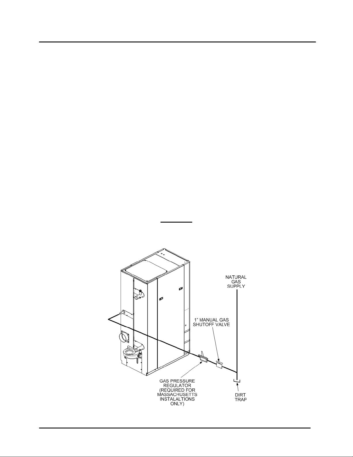
2.10.2 Manual Gas Shutoff Valve
A manual shut-off valve must be installed in the gas supply line upstream of the Heater as shown in
Figure 2-8. Maximum allowable gas pressure to the Heater is 14” W.C.
NOTE
Paragraph 2.10.3 appl ies only to water heater install ations within the Commonweal th of
Massachusetts.
2.10.3 External Gas Supply Regulator
For Massachusetts ins tallations, a m andator y externa l gas supp ly regulator m ust be pos itioned as shown
in Figure 2-6. The gas suppl y re gulator must be pr operly vented to outdoor s. Consult the loca l gas utility
for detailed requirements concerning venting of the the supply gas regulator.
NOTE
The external regulator must be capable of regulating 40,000 – 1,060,000 BTU/HR of
natural gas while maintaining a gas pressure of 7.0” W.C. to the unit.
CAUTION
A lock-up style regulator MUST be used when gas supply pressure will exceed
14” W.C.
Figure 2-8. Manual Gas Shut-Off Valve Location
Page 20 of 200 AERCO International, Inc. • 100 Oritani Dr. • Blauvelt, NY 10913 • Ph.: 800-526-0288 07/21/11
Page 21
Chapter 2 Innovation Series Water Heater s GF-128
Installation USER MANUAL OMM-0079_0B
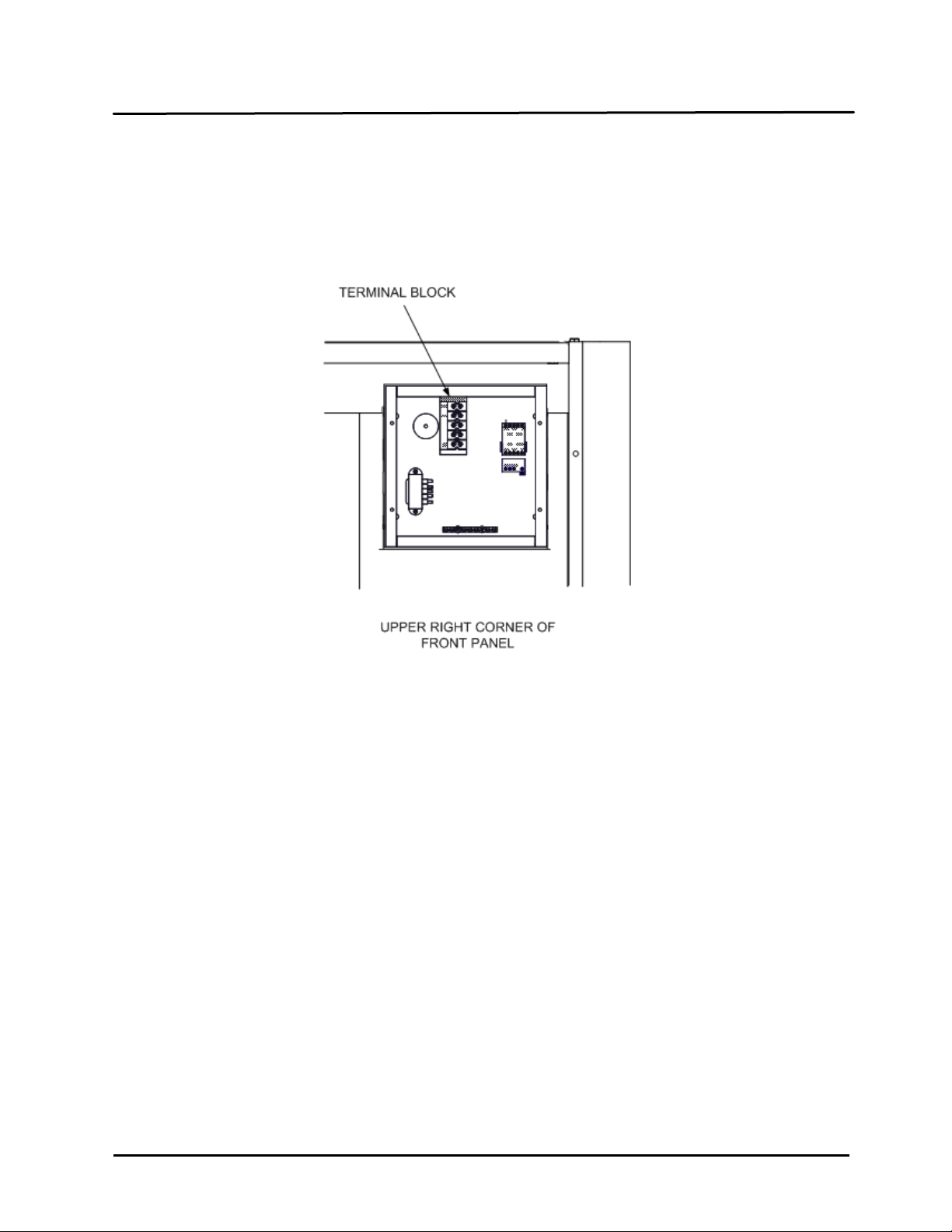
2.11 AC ELECTRICAL POWER WIRING
The AERCO Innovation Electrical Power Wiring Guide, GF-5060 (see Appen dix L), must be consulted
prior to connecting an y AC po wer wiri ng to t he un it. E xternal AC po wer c onnec tions ar e m ade to t he un it
inside the Power Box on t he front panel of the un it. Remove the front do or of the unit to ac ces s the Po wer
Box mounted directly abov e the Contr ol Box. Loos en the f our Power Box cover screws and r em ove cover
to access the AC terminal connections inside the Power Box (Figure 2-9).
Figure 2-9. Power Box With Cover Removed
NOTE
All electrical condu it and hard ware must be ins talled so that it does not i nterfere with th e
removal of any unit covers , inhibit service/maintenance, or prev ent access between the
unit and walls or another unit.
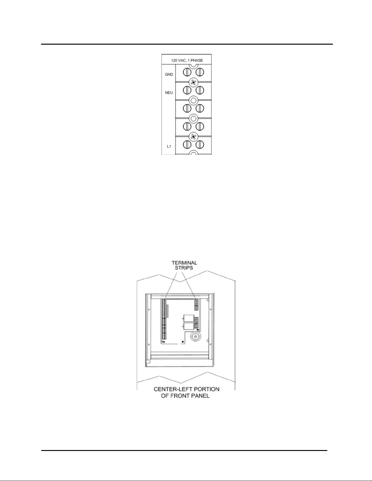
2.11.1 Electrical Power Requirements
The AERCO Innovation He ater acc epts 120 V AC, s in g le-ph as e, 60 H z @ 20 A. The Power Box contains a
terminal block as shown in Figure 2-8. In addition, a wiring diagram showing the required AC power
connections is provided on the front cover of the Power Box.
Each unit must be connected t o a dedicated electrical circuit. NO OTHER DE VICES SHOULD BE ON
THE SAME ELECTRICAL CIRCUIT AS THE HEATER.
A double-pole switch must be installed on the electrical supply line in an easily accessible location to
quickly and safely discon nect electrical servic e. DO NOT attach the switch t o sheet metal enclosures of
the unit.
After placing the unit in s ervice, the ignit ion safety shutof f device must be tested. If an external elec trical
power source is used, the insta lled boiler must be electrically bonded to gro und in accordance with the
requirements of the authority having jurisdiction. In the absence of such requirements, the installation
shall conform to National Electrical Code (NEC), ANSI/NFPA 70 and/or the Canadian Electrical Code
(CEC) Part I, CSA C22.1 Electrical Code.
For electrical power wiring diagrams, see the AERCO Innovation Electrical Power Wiring Guide, (GF-
5060).
07/21/11 AERCO International, Inc. • 100 Oritani Dr. • Blauvelt, NY 10913 • Ph: 800-526-0288 Page 21 of 200
Page 22
GF-128 Innovation Series Water He aters Chapter 2
OMM-0079_0B USER MANUAL Installation
2.12 FIELD CONTROL WIRING
Each unit is fully wired f rom the f actor y with an i ntern al operat ing co ntrol s ystem . No f ield contr ol wiri ng is
required for normal operation. Howe ver, th e C -More control s ystem us ed with all Innovation H eater s does
allow for some c ontrol and monitoring features. Wir ing connections f or these features are made in the
Input/Output (I/O) Box. T he I/O Box is located on the upper -left portion of the unit f ront panel (Figure 2-
11) behind the rem ovable front panel door. To acces s the I/O Box terminal strips shown in Figure 2-11,
loosen the four cover screws and rem ove the cover. All field wiring is ins talled from the rear of the panel
by routing the wires through one of the four bushings provided.
Figure 2-10. AC Terminal Block Configurations
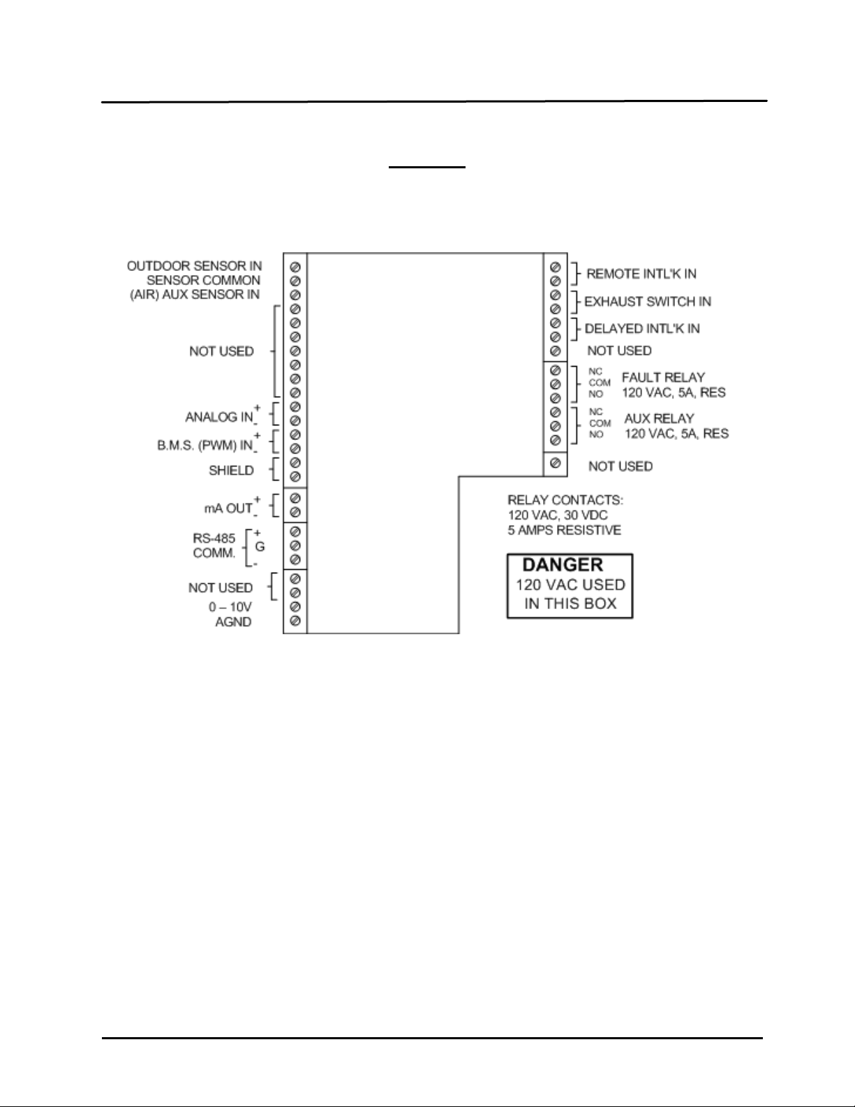
Refer to the wiring diagra m provided on the cover of the I/O Box (F igure 2-12) when making all wiring
connections.
Figure 2-11. Input/Output (I/O) Box Location
Since identical I/O Boxes are used with both AERCO gas-fired boilers and water heater s, some of the
input and output connectio ns apply only to boilers while oth ers are common to both boilers and heaters.
These I/O Box connections are noted in the following paragraphs.
Page 22 of 200 AERCO International, Inc. • 100 Oritani Dr. • Blauvelt, NY 10913 • Ph.: 800-526-0288 07/21/11
Page 23
Chapter 2 Innovation Series Water Heater s GF-128
Installation USER MANUAL OMM-0079_0B
CAUTION
DO NOT make any connections to the I/O Box terminals labeled “NOT USED”.
Attempting to do so may cause equipment damage.
Figure 2-12. I/O Box Terminal Strips
2.12.1 Outdoor Air Sensor
Not Applicable to Water Heaters.
2.12.2 AUX SENSOR IN
The AUX SENSOR IN terminals can be used to add an additional temperature sensor for monitoring
purposes. This input is always enabled and is a view onl y input that can be seen in the o perating menu.
The sensor must be wired to the AUX SENSOR IN and SENSOR COMMON and must be similar to
AERCO BALCO wire sensor P/N 12449. A resistance chart for this sensor is located in APPENDIX C.
2.12.3 ANALOG IN
The ANALOG IN + and – terminals are used when an external signal is used to change the setpoint
(Remote Setpoint Mode) of the heater.
Either a 4 to 20 mA /1 to 5 VDC or a 0 to 20 m A/ 0 to 5 VDC signal ma y be used to vary the setpoint or
air/fuel valve posi tion. The factory default setting is for 4 to 20 mA / 1 to 5 VD C, however this may be
changed to 0 to 20 mA / 0 to 5 VDC using the Configuration Menu described in Chapter 3.
If voltage rather than current is selected as the drive signal, a DIP s witch must be set on the PMC Board
located inside the Control Box. Contact the AERCO factory for information on setting DIP switches.
07/21/11 AERCO International, Inc. • 100 Oritani Dr. • Blauvelt, NY 10913 • Ph: 800-526-0288 Page 23 of 200
Page 24

GF-128 Innovation Series Water He aters Chapter 2
OMM-0079_0B USER MANUAL Installation
All supplied signals must be floating (unground-ed) signals. Connections between the source and the
Heater’s I/O Box mus t be made using tw isted shielded pa ir of 18–2 2 AW G wire such as Belde n 9841(see
Figure 2-12). Polarit y must be maintai ned and the shield m ust be connecte d only at the source end and
must be left floating (not connected) at the Heater’s I/O Box.
Whether using voltage or current f or the drive si gnal, the y are linearl y mapped to a 40°F to 240°F setpoint
or a 0% to 100% air/fuel valve position. No scaling for these signals is provided
2.12.4 B.M.S. (PWM) IN
Not Applicable to Water Heaters
2.12.5 SHIELD
The SHIELD terminals are used to terminate any shields used on sensor wires connected to the unit.
Shields must only be connected to these terminals.
2.12.6 mA OUT
These terminals prov ide a 4 to 20 m A output that c an be used to m onitor setpoi nt ( 40°F to 24 0°F), outlet
temperature (30°F to 240°F), or air/f uel valve positio n (0% to 100% o pen). This function is enabled in the
Configuration Menu (Chapter 3, Table 3-4).
2.12.7 EXHAUST SENSOR IN
These terminals permit an exhaust sensor to be connected to the exhaust manifold of the heater.
2.12.8 INTERLOCKS
The unit offers two interlock circuits for interfacing with Energy Management Systems and auxiliary
equipment such as pumps or louvers or other accessories. These interlocks are called the Remote
Interlock and Dela yed Interlock (Figure 2-12). T he wiring terminals for these interlocks ar e located inside
the I/O Box on the left side of the unit. The I/O Box cover contains a wiring diagram which shows the
terminal strip locations for these interlocks (REMOTE INTL’K IN and DELAYED INTL’K IN). Both
interlocks, described below, are factory wired in the closed position.
NOTE:
Both the Delayed Interloc k and Remote Interlock must be in the clos ed pos iti on for the unit
to fire.
2.12.8.1 REMOTE INTERLOCK IN
The remote interlock circuit is provided to remotely start (enable) and stop (disable) the unit if desired. The
circuit is l abeled REMOTE INT L’K IN and is located inside t he I/O Box on the left s ide of the unit. The
circuit is 24 VAC and comes factory pre-wired closed (jumped).
2.12.8.2 DELAYED INTERLOCK IN
The delayed interlock is typically used in conjunction with the auxiliary relay described in paragraph
2.12.10. This interloc k circuit is located in t he purge sec tion of the star t string. It can be connec ted to the
proving device (end switch, flow switch etc.) of an auxiliary piece of equipment started by the unit’s
auxiliary relay. The delayed interlock must be closed for the heater to fire. If the delayed interlock is
connected to a proving device that requires time to close (make), a time delay (Aux Start O n Dly) that
holds the start sequence of the unit long enough for a proving switch to make (close) can be programmed.
Should the proving switch not prove within the programm ed time frame, the unit will shut down. T he Aux
Start On Dly can be programm ed from 0 to 120 seconds. This option is locate in the Configuration Men u
(Chapter 3).
Page 24 of 200 AERCO International, Inc. • 100 Oritani Dr. • Blauvelt, NY 10913 • Ph.: 800-526-0288 07/21/11
Page 25

Chapter 2 Innovation Series Water He ate rs GF-128
Installation USER MANUAL OMM-0079_0B
2.12.9 FAUL T RELAY
The fault relay is a single p ole double thr ow (SPDT ) relay having a nor mall y open and norm ally closed set
of relay contacts that are r ated for 5 amps at 120 VAC and 5 am ps at 30 VDC. T he relay energi zes when
any fault condition occurs and remains energized until the fault is cleared and the CLEAR button is
depressed. The fault relay connections are shown in Figure 2-12.
2.12.10 AU XILIARY RELAY CONT ACTS
Each unit is equipped with a single pole double throw (SPDT) relay that is energized when there is a
demand for heat a nd de-energized after the dem and for heat is satisfied. The relay is provided for the
control of auxiliary eq uipment, such as pumps and louvers, or c an be used as a unit status ind ictor (fir ing
or not firing). Its contacts are rated for 120 VAC @ 5 amps. Refer to Figure 2-12 to locate the AUX RELAY
terminals for wiring connections.
2.13 FLUE GAS VENT INSTALLATION
AERCO Gas Fired Venting and Combustion Air Guide, GF-5050 (see Appendix K) must be consulted
before any flue or combustion air venting is designed or installed. Suitable, U/L approved, positive
pressure, watertight vent materials MUST be used for safety and UL certification. Because the unit is
capable of dischargi ng low temperature exha ust gases, the flue must be p itched back towards the u nit a
minimum of 1/4" per foot to avoid any condensate pooling and to allow for proper drainage.
While there is a positive flue pressure during operation, the combined pressure drop of vent and
combustion air systems must not exceed 140 equiva lent feet of 1.9” W.C. Fittings as well as pipe lengt hs
must be calculated as part of the equivalent length. For a natural draft installation the draft must not
exceed - 0.10” W .C. These factors must be planned into the vent installation. If the m aximum allowable
equivalent lengths of piping are exceeded, the unit will not operate properly or reliably.
For Massachusetts installations, the Heatfab Division of the Selkirk Corporation provides vent systems
which conform to all applicabl e requirem ents for installations within the Comm onwealth of Mass achusetts.
Contact information for this supplier is as follows:
Selkirk Corporation
Heatfab Division
130 Industrial Blvd.
Turners Falls, MA 01376
Phone: 1-800-772-0739
www.heat-fab.com
2.14 COMBUSTION AIR
The AERCO Gas-Fired He ater Venting and Combustion Air Guide , GF-5050 MUST be consulted before
any flue or inlet air venting is designed or installed. Air supply is a direct requirement of ANSI 223.1,
NFPA-54, CSA B149. 1 and local codes. These codes should be consulted before a perm anent design is
determined.
The combustion air must be free of chlorine, halogenated hydrocarbons or other chemicals that can
become hazardous when used in gas-fired equipment. Common sources of these compounds are
swimming pools, degreas ing compounds, plast ic processing, and ref rigerants. Whene ver the environm ent
contains these t ypes of chemicals, com bustion air MUST be su pplied from a clean area outdoors for the
protection and longevity of the equipment and warranty validation.
The more common methods of combustion air supply are outlined in the following paragraphs. For
combustion air suppl y from ducting, cons ult the AERC O GF-5050, Gas F ired Ven ting and Combus tion Air
Guide.
07/21/11 AERCO International, Inc. • 100 Oritani Dr. • Blauvelt, NY 10913 • Ph: 800-526-0288 Page 25 of 200
Page 26

GF-128 Innovation Series Water He aters Chapter 2
OMM-0079_0B USER MANUAL Installation
2.14.1 Combustion From Outside the Building
Air supplied from outside the building must be provid ed through two permanent openin gs. For each unit
these two openings m ust have a free area of not less than one squar e inch for each 4000 BTUs input of
the equipment or 250 s qu ar e inch es of f r ee area. T he f r ee area must take into account r es tr ic tio ns s uc h a s
louvers and bird sc reens. For Canada i nstallations , refer to the requirem ents specified in CSA B149.1-10,
8.4.1 and 8.4.3.
2.14.2 Combustion Air from Inside the Building
When combustion air is provided from within the building, it must be supplied through two permanent
openings in an interior wall. Each opening must have a free area of not less than one square inch per 1000
BTUH of total input or 1000 square inches of free area. The free area must take into account any
restrictions, such as louvers.
2.15 SEALED COMBUSTION
The AERCO Innovation Water Heater is UL listed for 100%-sealed combustion. For sealed combustion
installations, the screen inlet air ductwork must then be attached direc t l y to the unit’s air inlet.
In a sealed combustion air application, the combustion air ducting pressure losses must be taken into
account when calculat ing the total maximum allowable v enting run. See the AERCO Innov ation Venting
and Combustion Air Gui de, GF-5050. When using the heater in a sealed c ombustion air configuration,
each unit must have a minimum 6 inch diameter connection at the unit.
Page 26 of 200 AERCO International, Inc. • 100 Oritani Dr. • Blauvelt, NY 10913 • Ph.: 800-526-0288 07/21/11
Page 27

Chapter 3 Innovation Series Water Heater s GF-128
Operation USER MANUAL OMM-0079_0B
CHAPTER 3. OPERATION
3.1 INTRODUCTION
The information in this Chapter provides a guide to the operation of the Innovation Water Heater using the
Control Panel mounted on the front of the unit. It is imperative that the initial startup of this unit be
performed by factor y trained personnel. Oper ation prior to initial startu p by factor y trained personnel will
void the equipment w arr ant y. In ad dit io n, th e f oll o wing WARNINGS and CAUT ION S must be observed at
all times.
CAUTION
All of the installation procedures in Chapter 2 must be completed before
attempting to start the unit.
WARNING
ELECTRICAL VOLTAGES IN THIS SYSTEM INCLUDE 120 AND 24 VOLTS AC.
IT MUST BE SERVICED ONLY BY FACTORY CERTIFIED SERVICE
TECHNICIANS
WARNING
DO NOT ATTEMPT TO DRY FIRE THE UNIT. STARTING THE UNIT
WITHOUT A FULL WATER LEVEL CAN SERIOUSLY DA MAGE THE UNIT AND
MAY RESULT IN INJURY TO PERSONNEL OR PROPERTY DAMAGE. THIS
SITUATION WILL VOID ANY WARRANTY.
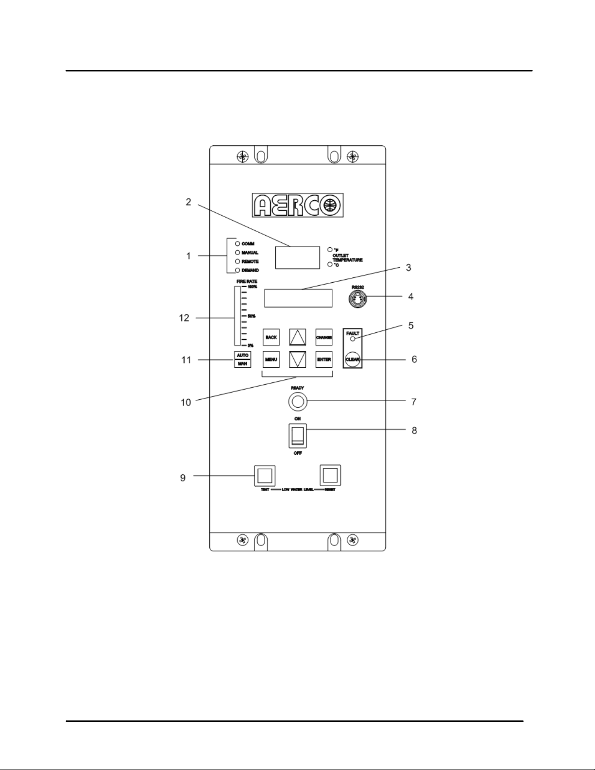
3.2 CO NTROL PANEL DESCRIPTION
The Innovation Control Panel shown in Figure 3-1 contains all of the controls, indicators and displays
necessary to opera te, adjust and troubleshoot the I nnovation Water Heater. T hese operating controls,
indicators and displays are listed and described in Table 3-1. Additional information on these items is
provided in the individual operating procedures provided in this Chapter.
07/21/11 AERCO International, Inc. • 100 Oritani Dr. • Blauvelt, NY 10913 • Ph: 800-526-0288 Page 27 of 200
Page 28
GF-128 Innovation Series Water He aters Chapter 3
OMM-0079_0B USER MANUAL Operation
Figure 3-1. Control Panel Front View
Page 28 of 200 AERCO International, Inc. • 100 Oritani Dr. • Blauvelt, NY 10913 • Ph.: 800-526-0288 07/21/11
Page 29

Chapter 3 Innovation Series Water Heater s GF-128
FUNCTION
Operation USER MANUAL OMM-0079_0B
Table 3-1 Operating Controls, Indicators and Displays
ITEM
NO.
CONTROL, INDICATOR
OR DISPLAY
LED Status Indicators
1
COMM
MANUAL
REMOTE
DEMAND
OUTLET
2
TEMPERATURE
Display
3 VFD Display Vacuum Fluorescent Display (VFD) consists of 2 lines each
Four Status LEDs indicate the current operating status as
follows:
Lights when RS-232 communication is occurring
Lights when the unit is being controlled using the front panel
keypad.
Lights when the unit is being controlled by an external signal
from an Energy Management System
Lights when there is a demand for heat.
3–Digit, 7–Segment LED display continuously displays the
outlet water temperature. The °F or °C LED next to the
display lights to indicate whether the displayed temperature is
in degrees Fahrenheit or degrees Celsius. The °F or °C blinks
when operating in the Deadband Mode.
capable of displaying up to 16 alphanumeric characters. The
information displayed includes:
Startup Messages
Fault Messages
Operating Status Messages
Menu Selection
RS-232 Port
4
FAULT Indicator Red FAULT LED indicator lights when a heater alarm
5
CLEAR Key Turns off the FAULT indicator and clears the alarm message
6
READY Indicator
7
ON/OFF Switch
8
LOW WATER LEVEL
9
TEST/RESET Switches
Port permits a Laptop Computer or External Modem to be
connected to the unit’s Control Panel.
condition occurs. An alarm message will appear in the VFD.
if the alarm is no longer valid. Lockout type alarms will be
latched and cannot be cleared by simply pressing this key.
Troubleshooting may be required to clear these types of
alarms.
Lights ON/OFF switch is set to ON and all Pre-Purge
conditions have been satisfied.
Enables and disables heater operation.
Allows operator to test operation of the water level monitor.
Pressing TEST opens the water level probe circuit and
simulates a Low Water Level alarm.
Pressing RESET resets the water level monitor circuit.
Pressing the CLEAR key (item 6) resets the display.
07/21/11 AERCO International, Inc. • 100 Oritani Dr. • Blauvelt, NY 10913 • Ph: 800-526-0288 Page 29 of 200
Page 30

GF-128 Innovation Series Water He aters Chapter 3
FUNCTION
OMM-0079_0B USER MANUAL Operation
Table 3-1 Operating Controls, Indicators and Displays – Continued
ITEM
NO.
CONTROL, INDICATOR
OR DISPLAY
10
MENU Keypad
MENU
BACK
▲ (UP) Arrow When in one of the main menu categories (Figure 3-2),
▼ (DOWN) Arrow When in one of the main menu categories (Figure 3-2),
CHANGE
Consists of 6 keys which provide the following functions for
the Control Panel Menus:
Steps through the main menu categories shown in Figure 3-
2. The Menu categories wrap around in the order shown.
Allows you to go back to the previous menu level without
changing any information. Continuously pressing this key
will bring you back to the default status display in the VFD.
Also, this key allows you to go back to the top of a main
menu category.
pressing the ▲ arrow key will select the displayed menu
category. If the CHANGE key was pressed and the menu
item is flashing, pressing the ▲ arrow key will increment the
selected setting.
pressing this key will select the displayed menu category. If
the CHANGE key was pressed and the menu item is
flashing, pressing the ▼ arrow key will decrement the
selected setting.
Permits a setting to be changed (edited). When the
CHANGE key is pressed, the displayed menu item will begin
to flash. Pressing the ▲ or ▼ arrow key when the item is
flashing will increment or decrement the displayed setting.
ENTER
11
12
AUTO/MAN Switch
VALVE POSITIO N
Bargraph
Saves the modified menu settings in memory. The display
will stop flashing.
This switch toggles the heater between the Automatic and
Manual modes of operation. When in the Manual (MAN)
mode, the front panel controls are enabled and the
MANUAL status LED lights.
When in the Automatic (AUTO) mode, the MANUAL status
LED will be off and the front panel controls disabled.
20 segment red LED bargraph continuously shows the
Air/Fuel Valve position in 5% increments from 0 to 100%
Page 30 of 200 AERCO International, Inc. • 100 Oritani Dr. • Blauvelt, NY 10913 • Ph.: 800-526-0288 07/21/11
Page 31

Chapter 3 Innovation Series Water Heater s GF-128
Operation USER MANUAL OMM-0079_0B
3.3 CO NTROL PANEL MENUS
The Control Panel incorpo rates an extensive menu structure which p ermits the operator to set up, and
configure the unit. The m enu str ucture c onsists of f ive major menu categor ies w hich ar e applica ble to th is
manual. These categori es are shown in Figure 3-2. Each of the menus shown, contain options which
permit operating param eters to be viewed or chan ged. The menus are protected by a password l evels to
prevent unauthorized use.
Prior to entering th e correct password, the options contai ned in the Operat ion, Setup, Configurat ion and
Tuning Menu categories can be viewed. However, with the exception of Int ernal Setpoint Temperature
(Configuration Menu), none of the viewable menu options can be changed.
Once the valid level 1 password (159) is entered, the options listed in the Setup. Configuration and
Tuning Menus can be viewed and changed, if desired.
3.3.1 Menu Processing Procedure
Accessing and initiating ea ch menu and option is accomplished us ing the Menu Ke ys shown in Figure 3-
1. Therefore, it is imperative that you be thoroughly familiar with the following basic steps before
attempting to perform specific menu procedures.
1. The Control Panel will nor mally be in the Operating Menu and the VF D will display the current unit
status. Pressing the ▲ or ▼ arrow key will display the other available data items in the Operating
Menu.
2. Press the MENU k ey. The displa y will show the Setup Men u, whic h is th e nex t menu c ateg ory sh own
in Figure 3-2. This m enu contains th e Passwor d option which mus t be entered if other m enu options
will be changed.
3. Continue pressing the MENU key until the desired menu is displayed.
4. With the desired menu displayed, press the ▲ or ▼ arrow key. The first option in the selected menu
will be displayed.
5. Continue to press the ▲ or ▼ arrow key until the desired menu option is displayed. Pressing the ▲
arrow key will displa y the available m enu options in the Top-Down sequence. Pressing the ▼ arrow
key will displa y the options in the Bottom -Up sequence. T he menu optio ns will wr ap-around after the
first or last available option is reached.
6. To change the value or set ting of a displayed menu option, pres s the CHANGE key. The displa yed
option will begin to flash. Press the ▲ or ▼ arrow key to scroll through the available menu option
choices for the option to be changed. The menu option choices do not wrap around.
7. To select and store a changed menu item, press the ENTER key.
07/21/11 AERCO International, Inc. • 100 Oritani Dr. • Blauvelt, NY 10913 • Ph: 800-526-0288 Page 31 of 200
Page 32

GF-128 Innovation Series Water He aters Chapter 3
OPERATING
SETUP
CONFIGURATION
TUNING
LEVEL 1 PWD
OMM-0079_0B USER MANUAL Operation
Figure 3-2. Menu Structure
NOTE
The following paragraphs provide brief descriptions of the options contained in each
menu. Refer to Appendix A for detailed descriptions of each menu option. Refer to
Appendix B for listings and descriptions of displayed startup, status and error messages.
3.4 O PERATING MENU
The Operating Menu displa ys a number of key operating parameters f or the unit as listed in Table 3-2.
This menu is “R ead-Only” and does not allow person nel to change or adjust any displa yed items. Since
this menu is “Read-Only”, it can be viewed at any time without entering a password. Pressing the ▲
arrow key to display the menu items in the order listed (Top-Down). Pressing the ▼ arrow k e y wil l display
the menu items in reverse order (Bottom-Up).
Page 32 of 200 AERCO International, Inc. • 100 Oritani Dr. • Blauvelt, NY 10913 • Ph.: 800-526-0288 07/21/11
Page 33

Chapter 3 Innovation Series Water Heater s GF-128
Available Choices or Limits
Available Choices or Limits
Menu Item Display
Minimum
Maximum
Default
Operation USER MANUAL OMM-0079_0B
3.5 SETUP M ENU
The Setup Menu (Table 3-3) permits the operator to enter the u nit password (159) which is required to
change the menu options. To prevent unauthorized use, the password will time-out after 1 hour.
Therefore, the correc t password must be reentered when re quired. In addition to permitting passw ord
entries, the Setup Menu is also used to enter date and time, units of tem perature measurements and
entries required for external communication and control of the unit via the RS-232 port. A view-only
software version display is also provided to indicate the current Control Box software version.
NOTE
The Outdoor Temp displa y item shown with an asteris k in Table 3-2 will not be displa yed
unless the Outdoor Sens or function has been e nabled in the Configur ation Menu (Table
3-4).
Table 3-2. Operating Menu
Menu Item Display Minimum Maximum Default
Status Message
Active Setpoint 40°F 240°F
Inlet Temp 40°F 140°F
AIR Temp -70°F 245°F
Outdoor Temp* -70°F 130°F
Valve Position In 0% 100%
Valve Position Out 0% 100%
FFWD Temp 80°F 160°F
Flame Strength 0% 100%
Run Cycles 0 999,999,999
Run Hours 0 999,999,999
Fault Log 0 19 0
Table 3-3. Setup Menu
Passsword
0
9999 0
07/21/11 AERCO International, Inc. • 100 Oritani Dr. • Blauvelt, NY 10913 • Ph: 800-526-0288 Page 33 of 200
Language English English
Time 12:00 am 11:59 pm
Date 01/01/00 12/31/99
Unit of Temp Fahrenheit or Celsius Fahrenheit
Comm Address 0 127 0
Baud Rate 2400, 4800, 9600, 19.2K 9600
Software Ver 0.00 Ver 9.99
Page 34

GF-128 Innovation Series Water He aters Chapter 3
Available Choices or Limits
Menu Item Display
Minimum
Maximum
Default
OMM-0079_0B USER MANUAL Operation
3.6 CO NF IG URATION MENU
The Configuration Menu shown in Table 3-4 permits adjustment of the Internal Setpoint (Setpt)
temperature regardles s of wheth er the valid password has been e ntere d. Se tpt is r equire d f or operati on i n
the Constant Setpoint mode. The remaining options in this menu require the valid password to be
entered, prior to chang ing existing entries. This m enu contains a number of other configuration settings
which may or may not be displayed, depending on the current operating mode setting.
NOTE
The Configuration Men u settings shown in Table 3-4 are Fac tory-Set in accordan ce with
the requirements spec ified for each individual order. T herefore, under normal operating
conditions, no changes will be required.
Table 3-4. Configuration Menu
Internal Setpt
Unit Type
Unit Size
Fuel Type
Water Heater Mode
Remote Signal
(If Mode = Remote
Setpoint, Direct Drive
or Combination)
Bldg Ref Temp
(If Mode = Outdoor
Reset)
Reset Ratio
(If Mode = Outdoor
Reset)
Outdoor Sensor
Lo Temp
Hi Temp Limit 130°F
Limit
KC Boiler, KC Boiler LN,
BMK Boiler, BMK Boiler LN,
BMK Boiler Dual, KC Water
Heater, KC Water Heater LN,
INN
0.5 MBTU, 1.0 MBTU
1.5 MBTU, 2.0 MBTU
3.0 MBTU, 3.5 MBTU
4.0 MBTU, 5.0 MBTU
6.0 MBTU
Natural Gas, Propane Natural Gas
Constant Setpoint,
Remote Setpoint,
4 – 20 mA/1 – 5V
1.0 MBTU
Constant
Setpoint
4 – 20 mA,
0 -20 mA/0 – 5V
PWM Input (BMS)
Network
40°F 230°F 70°F
0.1 9.9 1.2
Enabled or Disabled Disabled
INN
1-5V
Page 34 of 200 AERCO International, Inc. • 100 Oritani Dr. • Blauvelt, NY 10913 • Ph.: 800-526-0288 07/21/11
System Start Tmp
(If Outdoor Sensor =
Enabled)
30°F 100°F 60°F
Page 35

Chapter 3 Innovation Series Water Heater s GF-128
Available Choices or Limits
Menu Item Display
Minimum
Maximum
Default
Available Choices or Limits
Menu Item Display
Minimum
Maximum
Default
Operation USER MANUAL OMM-0079_0B
Table 3-4. Configuration Menu - Continued
Setpt Lo Limit
Setpt Hi Limit
Temp Hi Limit
Max Valve Position
Pump Delay Timer
Aux Start On Dly
Failsafe Mode Shutdown or Constant Setpt Shutdown
*Analog Output
(See CAUTION at
end of Table 3-4 )
Low Fire Timer 2 sec. 600 sec. 2 sec.
Setpt Limiting Enabled or Disabled Disabled
Setpt Limit Band 0°F 10°F 0
Network Timeout 5 Sec 999 Sec 30 Sec
HI DB Setpt EN 0% 100% 30%
Demand Offsert 0 25 0
Deadband High 0 25 0
40°F Setpt Hi Limit 60°F
Setpt Lo Limit 220°F 140°F
40°F 240°F 160°F
40% 100% 100%
0 min. 30 min. 0 min.
0 sec. 120 sec. 0 sec.
Off, Setpoint, Outlet Temp,
Valve Position 4-20 mA,
Valve Position 0-10V
*Valve
Position
0-10V
Deadband Low 0 25 0
*CAUTION:
DO NOT CHANGE the Analog Output Menu Item from its Default setting
(Valve Position 0-10V
3.7 TUNING MENU
The Tuning Menu item s in T able 3-5 ar e Factor y set for eac h indi vidual uni t. Do not c hange t hese m enu
entries unless specifically requested to do so by Factory-Trained personnel.
Prop Band
Integral Gain 0.00 2.00 1.6
Derivative Time 0.0 min 2.00 min 0.10 min
Reset Defaults? Yes, No, Are You Sure? No
).
Table 3-5. Tuning Menu
1°F
120°F 8°F
07/21/11 AERCO International, Inc. • 100 Oritani Dr. • Blauvelt, NY 10913 • Ph: 800-526-0288 Page 35 of 200
Page 36

GF-128 Innovation Series Water He aters Chapter 3
OMM-0079_0B USER MANUAL Operation
3.8 START SEQUENCE
When the Control B ox ON/OFF switch is set to the O N pos ition, it chec k s all pre -pur ge saf et y switches to
ensure they are closed. These switches include:
• Safety Shut-Off Valve Proof of Closure (POC) switch
• Low Water Level switch
• High Water Temperature switch
• High Gas Pressure switch
• Low Gas Pressure switch
• Blower Proof switch
If all of the above switches ar e closed, the READY light above t he ON/OFF swit ch will light and the unit
will be in the Standby mode.
When there is a demand for hot water, the following events will occur:
NOTE
If any of the Pre-Purge safety dev ice switches are open, the appropriate fault mes sage
will be displayed. Also, the appropriate mes sages will be displayed thr oughout the star t
sequence, if the required conditions are not observed.
1. The DEMAND LED status indicator will light.
2. The unit checks to ensur e that the Proof of Clos ure (POC) s witch in the downstream Safety Shut-Off
Valve (SSOV) is closed. See Figure 3-3 for SSOV location.
Figure 3-3. SSOV Location
3. With all required safet y devic e sw itches c losed, a p ur g e cycle will be initiated and the f ollo win g event s
will occur:
(a) The Blower relay energizes and turns on blower.
(b) The Air/Fuel Valve rotates to th e full-open p urge position an d closes purge p osition switc h. The
dial on the Air/Fuel Valve (Figure 3-4) will read 100 to indicate that it is full-open (100%).
(c) The VALVE POSITION bargraph will show 100%.
Page 36 of 200 AERCO International, Inc. • 100 Oritani Dr. • Blauvelt, NY 10913 • Ph.: 800-526-0288 07/21/11
Page 37

Chapter 3 Innovation Series Water Heater s GF-128
Operation USER MANUAL OMM-0079_0B
Figure 3-4.
Air/Fuel Valve In Purge Position
4. Next, the blower proof switch on the Air/Fuel Valve (Figure 3-5) closes. The display will show Purging
and indicate the elapsed time of the purge cycle in seconds.
Figure 3-5. Blower Proof Switch
5. Upon completion of the purge cycle, the Control Box initiates an ignition cycle and the following
events occur:
(a) The Air/Fuel Valve rotates t o the l o w-f ire ig nit io n p os ition a nd c l os es the ignition switch. The dial
on the Air/Fuel Valve (Figur e 3-6) will read bet ween 25 and 35 to indic ate that the val ve is in the
low-fire position.
(b) The igniter relay is activated and provides ignition spark.
(c) The gas Safety Shut-Off Valve (SSOV) is energized (opened) allowing gas to flow into the
Air/Fuel Valv e.
07/21/11 AERCO International, Inc. • 100 Oritani Dr. • Blauvelt, NY 10913 • Ph: 800-526-0288 Page 37 of 200
Page 38

GF-128 Innovation Series Water He aters Chapter 3
OMM-0079_0B USER MANUAL Operation
Figure 3-6. Air/Fuel Valve In Ignition Position
6. Up to 7 seconds will be allowed for ignition to be detected. T he igniter relay will be turned off one
second after flame is detected.
7. After 2 seconds of continu ous flame, Flame Proven will be displayed and the flam e strength will be
indicated. After 5 seconds, the current date and time will be displayed in place of the flame strength.
8. With the unit firing pr operly, it will be co ntrolled by the temperature c ontroller circuitry. T he heater’s
VALVE POSITIO N will be continuously displayed on the front panel bargraph.
Once the demand for hot water has be en satisf ied, the Control Box will t urn off the SSOV gas v alve. T he
blower relay will be deactivated and the Air/Fuel Valve will be closed. Standby will be displayed.
3.9 START/STOP LEVELS
The start and stop le vels are the Air/Fuel Val ve positions (% open) that s tart and stop the unit, bas ed on
load. These levels are Factory preset as follows:
Start Level: 20%
Stop Level: 16%
Normally, these settings should not require adjustment.
Note that the energy input of the heater is not linearly related to the Air/Fuel Valve position. Refer to Table
3-6 for the relationsh ip betw een the e nergy inp ut and Air/Fuel Va lve posit ion for a unit r unning o n natural
gas.
Page 38 of 200 AERCO International, Inc. • 100 Oritani Dr. • Blauvelt, NY 10913 • Ph.: 800-526-0288 07/21/11
Page 39

Chapter 3 Innovation Series Water Heater s GF-128
0% 0 0
10% 0 0
16%
(Stop Level)
45,000
4.2%
20%
97,000
10%
30%
222,000
22%
40%
416,000
42%
50%
520,000
52%
60%
645,000
65%
70%
715,000
72%
80%
845,000
85%
90%
930,000
93%
100%
1,060,000
100%
Operation USER MANUAL OMM-0079_0B
Table 3-6. Relationship Between Air/Fuel Valve Position and Energy Input
For Unit Running On Natural Gas
Air/Fuel Valve Position
(% Open)
Energy Input
(BTU/Hr)
Heater Energy Input
(% of Full Capacity)
07/21/11 AERCO International, Inc. • 100 Oritani Dr. • Blauvelt, NY 10913 • Ph: 800-526-0288 Page 39 of 200
Page 40

GF-128 Innovation Series Water He ate rs Chapter 4
OMM-0079_0B USER MANUAL Initial Start-Up
This Page Is Intentionally Blank
Page 40 of 200 AERCO International, Inc. • 100 Oritani Dr. • Blauvelt, NY 10913 • Ph.: 800-526-0288 07/21/11
Page 41

Chapter 4 Innovation Series Water He ate rs GF-128
Initial Start-Up USER MANUAL OMM-0079_0B
CHAPTER 4. INITIAL START-UP
4.1 INITI AL START-UP REQUIREMENTS
The requirements for the initial start-up of the Innovation Water Heater consists of the following:
• Complete installation (Chapter 2)
• Set proper controls and limits (Chapter 3)
• Perform combustion calibration
• Test safety devices (Chapter 5)
All applicable installati on procedures in Chapter 2 must be fully completed pr ior to performing the initial
start-up of the unit. The i niti al start-up must be succ essf ully com pleted prior to putt ing the unit into ser vice.
Starting a unit without the pr oper piping, venting, or elec trical s ystem s can be dangerous and m ay void the
product warranty. The f ollowing start-up instructions shou ld be followed precisely in order to operate t he
unit safely and at a high thermal efficiency, with low flue gas emissions.
Initial unit start-up must be perform ed ONLY by AERCO factory trained s tart-up and service personnel.
After performing the start -up procedures in this Chapt er, it will be necessary to perf orm the Safety Device
Testing procedures specified in Chapter 5 to complete all initial unit start-up requirements.
An AERCO Gas Fired Startup Sheet, include d with each Innovation Heater, must be com pleted for each
unit for warranty validation and a copy must be returned promptly to AERCO at:
AERCO International, Inc.
100 Oritani Drive
Blauvelt, New York 10913
WARNING
DO NOT ATTEMPT TO DRY FIRE THE HEATER. STARTING THE UNIT
WITHOUT A FULL WATER LEVEL CAN SERI OUSLY DAMAGE THE UNIT AND
MAY RESULT IN INJURY TO PERSONNEL OR PROPERTY DAMAGE. THIS
SITUATION WILL VOID ANY WARRANTY.
4.2 TOO L S AND INSTRUMENTATION FOR COMBUSTION CALIBRATION
To properly perform combustion calibra tion, the proper ins truments and too ls must be used and correctly
attached to the unit . The following paragra phs outline the nec essary tools and instrumentation as well as
their installation.
4.2.1 Required Tools & Instrumentation
The following tools and instrumentation are necessary to perform combustion calibration of the unit:
• Digital Combustion Analyzer: O xygen accuracy to ± 0.4%; Carbon Monox ide (CO) and Nitrogen
Oxide (NOx) resolution to 1PPM.
• 16 inch W.C. manometer or equivalent gauge and plastic tubing.
• 1/8 inch NPT-to-barbed fittings for use with gas supply manometer or gauge.
• Small and large flat blade screwdrivers.
• Tube of silicone adhesive
07/21/11 AERCO International, Inc. • 100 Oritani Dr. • Blauvelt, NY 10913 • Ph: 800-526-0288 Page 41 of 200
Page 42

GF-128 Innovation Series Water He ate rs Chapter 4
OMM-0079_0B USER MANUAL Initial Start-Up
4.2.2 Installing Gas Supply Manometer
The gas supply manometer is installed in the gas train as follows:
1. Close the main manual gas supply shut-off valve upstream of the unit.
2. Remove the front door and left side panels from the heater to access the gas train components.
3. Remove the 1/8 inch NPT pipe plu g from the leak detection bal l valve on the downstream s ide of the
Safety Shut Off Valve (SSOV) as shown in Figure 4-1.
4. Install a NPT-to-barbe d fitti ng into the tap ped pl ug port.
5. Attach one end of the plastic tubing to the barbed fitting and the other end to the 16 inch W.C.
manometer.
Figure 4-1. 1/8 Inch Gas Plug Location
4.2.3 Accessing the Analyzer Probe Port
The unit contains a 1/8” NPT port at the rear of the exhaust manifold. This port is located above the
condensate drain conn ection as shown i n Figure 4-2. Pr epare the port for th e combustion anal yzer probe
as follows:
1. Refer to Figure 4-2 and remove the 1/8” NPT plug from the rear of the exhaust manifold.
2. If necessary, adjust the sto p on the combustion anal yzer probe so it will exten d mid-way into the flue
gas flow. DO NOT install the probe at this time.
Page 42 of 200 AERCO International, Inc. • 100 Oritani Dr. • Blauvelt, NY 10913 • Ph.: 800-526-0288 07/21/11
Page 43

Chapter 4 Innovation Series Water He ate rs GF-128
Initial Start-Up USER MANUAL OMM-0079_0B
Figure 4-2 Analyzer Probe Hole Location
4.3 NATURAL G AS COMBUSTION CALIBRATION
The Innovation Heat er is combustion c alibrated at the factory prior to sh ipping. However, r ecalibration as
part of initial start-up is nec essar y due to cha nges i n the l ocal alt itude, g as BT U content , gas s uppl y piping
and supply regulators. F actory Test Data sheets ar e shipped with each unit. These sheets must be filled
out and returned to AERCO for proper Warranty Validation.
It is important to perform the following procedure as outl ined. This will keep readj ustments to a minimum
and provide optimum performance.
1. Open the water supply and return valves to the unit and ensure that the system pumps are running.
2. Open the natural gas supply valve(s) to the unit.
3. Set the control panel ON/OFF switch to the OFF position.
4. Turn on external A C power to the unit. The displa y will show LOSS OF POWER and the time and
date.
5. Set the unit to the Manual Mode b y pressing the AUTO/MAN key. A flashing M anual Valve Position
message will be displayed with the present pos i tion in %. Also, the MANUAL LED will light.
6. Adjust the air/fuel valve position to 0% by pressing the ▼ arrow key.
7. Ensure that the leak detection ball valve downstream of the SSOV is open.
8. Set the ON/OFF switch to the ON position
9. Change the valve position to 29% using the ▲ arrow key. The unit should begin its s tart s equenc e a nd
fire.
07/21/11 AERCO International, Inc. • 100 Oritani Dr. • Blauvelt, NY 10913 • Ph: 800-526-0288 Page 43 of 200
.
Page 44

GF-128 Innovation Series Water He ate rs Chapter 4
Oxygen %
Carbon
NOx
6.5 %
<50 ppm
<15 ppm
OMM-0079_0B USER MANUAL Initial Start-Up
10. Next, verify that the gas pr essure downstream of the SSOV is within the rang e of 2.6” to 2.8” W.C . If
gas pressure adjustm ent is required, remove the brass hex nut on the SSOV ac tuator to access the
gas pressure adjustment screw (Figure 4-3). Make gas pressure adjustments using a flat-tip
screwdriver to obtain a gas pressure within the required range of 2.6” to 2.8” W.C.
Figure 4-3. Gas Pressure Adjustment Screw Location
11. Using the ▲ arrow key, Increas e the valve open position t o 100%. Verify that th e gas press ure at the
inlet of the SSOV is 7.0” W.C. Readjust the inlet gas pressure if necessary
12. Next, decrease the valve open position to 16% using the ▼ arrow key.
13. Insert the combustion analyzer probe int the 1/8” port at the rear of the exhaust manifold. Allow
enough time for the combustion analyzer to settle.
14. Verify that the oxygen (O2) level is within the range shown below Also, ensure that the carbon
monoxide (CO) and nitrogen oxide (NOx) readings do not exceed the values shown.
.
Combustion Oxygen Level at
16% Valve Position
± 0.5
Monoxide
15. If the oxygen level is not w i thin t he r equ ir ed t ol eranc e, the g as pres s ure on the downstream s ide of the
SSOV must be adjusted using the adjustm ent s crew on the SSO V regulat or (F igure 4-3). Slowly rotate
the gas pressure adjustment (approximately 1/4-turn increm ents). Allow the combustion analyzer to
stabilize following each adjustment. Clockwise rotation reduces the oxygen level, while
counterclockwise rotation increases the oxygen level.
16. Once the oxygen level is with in the required range, the gas pres sure on the downstream s ide of the
SSOV should be within the range of 2.6” to 2.8” W.C. at the 16% valve position.
17. Replace the brass cap on the SSOV gas pressure adjustment if it was previously removed.
18. This completes the combustion calibration procedure.
Page 44 of 200 AERCO International, Inc. • 100 Oritani Dr. • Blauvelt, NY 10913 • Ph.: 800-526-0288 07/21/11
Page 45

Chapter 4 Innovation Series Water He ate rs GF-128
Initial Start-Up USER MANUAL OMM-0079_0B
4.4 REASSEMBLY
Once the combustion calibration adjustments are properly set, the unit can be reassem bled for service
operation.
1. Set the ON/OFF switch in the OFF position.
2. Disconnect AC power from the unit.
3. Shut off the gas supply to the unit.
4. Remove the manom eter and barbed fittings and reinstall the NPT plug using a suitable pipe thread
compound.
5. Remove the combustion a nalyzer probe from the 1/8” vent hole in the exhaust manifold. Replace th e
1/8” NPT plug in the manifold.
6. Replace the unit’s side panels and front door.
4.5 TEMPERATURE CONTROL CALIBRATION
Although the unit com es factor y set and c a libr ate d f or a 130°F setpoint it is usually nec ess ary to recalibrate
temperature control. Ther e are two primar y adjustments f or performing temper ature calibration. T hese are
Min Load Adj and Max Load Adj (minimum and maximum load adjustment).
Adjustments to these s ettin gs are m ade at m inim um and m aximum load conditio ns and shou ld be m ade in
small increments from 1 to 3 degrees. Af ter making an adjustm ent, the outlet water tem perature must be
allowed to settle for several minutes prior to making any further adjustments.
When calibrating temperature control, observe the following:
1. The unit must be in the Auto mode of operation.
2. The Outlet Feedback option in the Tuning Menu must be set to OFF while performing calibration.
3. Monitor the OUTLET TEMPERATURE display and VALVE POSITION bar-graph to set load
conditions and observe the effect of adjustments.
4. Perform the calibration using the Tuning Menu of the C-More Control Box.
5. Make small adjustments and allow time between adjustments for the outlet water temperature to
stabilize.
6. Maintain water flow as constant as possible during these adjustments.
7. Ensure that recirculation loops are operational while the calibration is being performed.
4.5.1 Setting the Outlet Water Temperature Setpoint
The setpoint t emper ature of t he unit may be cha nged b y following the pr ocedure below. How ever, once a
setpoint has been c hanged, recalibratio n may be necessar y. The temperature cali bration procedures ar e
provided in paragraphs 4.5.2 and 4.5.3.
To adjust the unit’s setpoint, proceed as follows:
1. Press the MENU key until Configuration Menu is displayed.
2. Press the ▲ or ▼ arrow key until Internal Setpt is displayed along with the present setpoint
temperature.
3. To change the setpoint, press the CHANGE key. The display will begin to flash.
4. Press the ▲ or ▼ arrow key until the desired setpoint is displayed.
5. Press the ENTER key to save the change.
07/21/11 AERCO International, Inc. • 100 Oritani Dr. • Blauvelt, NY 10913 • Ph: 800-526-0288 Page 45 of 200
Page 46

GF-128 Innovation Series Water He ate rs Chapter 4
OMM-0079_0B USER MANUAL Initial Start-Up
4.5.2 Minimum Load Adjustment
With the unit in operation, check the temperature control at minimum load as follows:
1. While monitoring the VAL V E PO SITION bar-graph, create a minimum load on the system that will yield
a steady valve position between 25% and 35% .
NOTE
It may be desirable to shut off the outlet valve and use the hose bib (s ee Figure 2-4) to
simulate a minimum flow load condition.
2. Wait several minutes to allow the outlet temperature to stabilize under load conditions.
3. Once stabilized, the OUTLET TEMPERATURE display should read no more than 2 to 3 degrees
above the unit’s setpoint.
4. If the outlet temperature is stabilized, proceed to the Maximum Load Adjustment procedure in
paragraph 4.5.3. If the temperature is not stabilized, proceed to step 5.
5. Press the MENU key and select the Tuni ng Men u.
6. Press the ▲ or ▼ arrow key until Min Load Adj is displayed.
7. Press the CHANGE ke y. The displ a y will begin to flas h.
8. Raise or lower the minimum load adjustment in increments of one or two using the ▲ or ▼ arrow key.
Increasing this value will increase outlet water temperature, while decreasing it will decrease outlet
water temperature.
9. Press ENTER to save the change. Allow time for the system to stabilize between adjustments
10. Repeat steps 5 through 9 a s neede d unti l the tem per ature is st abili zed at no m ore than 2 to 3 degrees
above the unit’s setpoint.
4.5.3 Maximum Load Adjustment
Check the temperature control at maximum load as follows:
1. While monitoring the VALVE POSITION bar-graph, create a maximum load on the s ystem that will
yield a steady valve position between 80% and 90%.
NOTE
It may be necessary to open the outlet valve if it was closed during minimum load
adjustment to obtain a sufficient flow rate for maximum adjustment.
2. Wait several minutes to allow the outlet water temperature to stabilize under load conditions.
3. Once stabilized, the OUTLET TEMPERATURE display should read no more than 2 to 3 degrees
below the unit’s setpoint.
4. If the outlet temper ature is stabilized , no adjustm ent is necessar y. If the temperatur e is not st abilized,
proceed to step 5.
5. Press the MENU key and select the Tuning Menu.
6. Press the ▲ or ▼ arrow key until Max Load Adj is displayed.
7. Press the CHANGE key. The display will begin to flash.
8. Raise or lower the maxim um load adjustment using the ▲ or ▼ arrow key. Increasing this value will
increase outlet water temperature, whi le decr easi ng it wil l decrease water temperature.
9. Press ENTER to save the change. Allow time for the system to stabilize between adjustments.
Page 46 of 200 AERCO International, Inc. • 100 Oritani Dr. • Blauvelt, NY 10913 • Ph.: 800-526-0288 07/21/11
Page 47

Chapter 4 Innovation Series Water He ate rs GF-128
Initial Start-Up USER MANUAL OMM-0079_0B
10. Repeat steps 5 through 9 as needed u ntil the tem perature is stabilized 2 to 3 degr ees belo w the unit’s
setpoint.
If the outlet temperature does not maintain setpoint after a reasonable amount of time and adjustment,
contact your local AERCO representative.
NOTE:
After performing Temperature Calibration and prior to placing the water heater into
4.6 OVER-TEMPERATURE LIMIT SWITCHES
The unit contains both aut omatic and manual reset over-tem perature limit switches. These switches are
mounted on a plate as sho wn in Figure 4-4. T he switches can be accessed by opening the front pane l
door of the unit. T he manual res et s witch is not adjust able and is perm anently fix ed at 20 0°F. T his switch
will shut down and lock out the heater if the water temperature exceeds 200°F. Following an overtemperature condit ion, it must be m anually reset b y pressing the RE SET button bef ore the heater c an be
restarted. The autom atic reset over-temperature switch is adjustable and a llows the unit to restart, o nce
the temperature drops below its temperature setting. Set the automatic over-temperature switch to the
desired setting.
service, be sure to set the Outlet Feedback option in the Tunin g Menu back to ON.
Figure 4-4. Over Tem peratu re Limit Switch Location
07/21/11 AERCO International, Inc. • 100 Oritani Dr. • Blauvelt, NY 10913 • Ph: 800-526-0288 Page 47 of 200
Page 48

GF-128 Innovation Series Water He ate rs Chapter 4
OMM-0079_0B USER MANUAL Initial Start-Up
This Page Is Intentionally Blank
Page 48 of 200 AERCO International, Inc. • 100 Oritani Dr. • Blauvelt, NY 10913 • Ph.: 800-526-0288 07/21/11
Page 49

Chapter 5 Innovation Series Water Heater s GF-128
Safety Device Testing USER MANUAL OMM-0079_0B
CHAPTER 5. SAFETY DEVICE TESTING
5.1 TE STING OF SAFETY DEVICES
Periodic safety device testing is required to ensure that the control system and safety devices are
operating properly. The heater control system comprehensively monitors all combustion-related safety
devices before, during and af ter the start sequence. The following tes ts check to ensur e that the system
is operating as designed.
Operating controls and safety devices should be tested on a regular basis or following service or
replacement. All testing must conform to local codes such as ASME CSD-1.
NOTE
MANUAL and AUTO modes of operation are required to p erform the follo wing tests. For
a complete explanation of these modes, see Chapter 3.
NOTE
It will be necessar y to remove the f ront door an d side panels f rom the unit to p erform the
following tests.
WARNING
ELECTRICAL VOLTAGES IN THIS SYSTEM MAY INCLUDE 120 AND 24
VOLTS AC. POWER MUST BE REMOVED PRIOR TO PERFORMING W IRE
REMOVAL OR OTHER TEST PROCEDURES THAT CAN RESULT IN
ELECTRICAL SHOCK.
5.2 LO W GAS PRESSURE FAULT TEST
Refer to Figure 5-1 an d ens ure th at the le ak detecti on bal l valv e locate d at t he high gas pr ess ur e switc h is
closed.
1. Remove the 1/8“ plug fr om the ball valve at the low gas pr essur e switch sho wn in the lo wer porti on of
Figure 5-1.
2. Install a 0 – 16“ W.C. manometer or a W.C. gauge where the 1/8" plug was removed.
3. Slowly open the ball valve near the low gas pressure switch.
4. Place the unit in Manual Mode and adjust the air/fuel valve position (% open) between 25 and 30%.
5. While the unit is firing, slowly close the external manual gas shut-off valve.
6. The unit should shut dow n and d ispla y a LOW G AS PRES SUR E fault message a t approxim atel y 2.6”
W.C. The FAULT indicator should also start flashing.
7. Fully open the external manual gas shut-off valve and press the CLEAR button on the Control Box.
8. The fault message should clear and the FAULT indicator should go off. The unit should restart.
9. Upon test completion, close the ball valve and remove the manometer. Replace the 1/8“ plug
removed in step 1.
07/21/11 AERCO International, Inc. • 100 Oritani Dr. • Blauvelt, NY 10913 • Ph: 800-526-0288 Page 49 of 200
Page 50

GF-128 Innovation Series Water He aters Chapter 5
OMM-0079_0B USER MANUAL Safety Device Testing
Figure 5-1. Low & High Gas Pressure Testing
5.3 HIGH GAS PRESSURE TEST
To simulate a high gas pressure fault, refer to Figure 5-1 and proceed as follows:
1. Remove the 1/8“ plug from the leak detection ball valve shown in Figure 5-1.
2. Install a 0 – 16” W.C. manometer (or W.C. gauge) where the 1/8” plug was removed.
3. Slowly open the leak detection ball valve
4. Start the unit in Manual mode at a valve position (firing rate) of 25%.
5. Slowly increase the gas pressure using the adjustment screw on the SSOV.
6. The unit should shut down and display a HIGH GAS PRESSURE fault message when the gas
pressure exceeds 4.0” W.C. The FAULT indicator should also start flashing.
7. Reduce the gas pressure back to 2.8” W.C.
8. Press the CLEAR button on the Control Box to clear the fault.
9. The fault message should clear and the FAULT indicator should go off. The unit should restart.
10. Upon test completion, close the ball valve and remove the manometer. Replace the 1/8“ plug
removed in step 1.
5.4 LO W WATER LEVEL FAULT TEST
To simulate a low water level fault:
1. Set the ON/OFF switch to the OFF position
2. Close the water shut-off valves in the supply and return piping to the unit.
3. Slowly open the dr ai n va lve on the r ear of the unit. If necessary the uni t’s r e lief valve may be o pen ed
to aid in draining.
4. Continue draining th e unit until a LOW W ATER LEVEL fau lt message is displayed and t he FAULT
indicator flashes.
5. Place the unit in the Manual Mode and raise the valve position above 30%.
Page 50 of 200 AERCO International, Inc. • 100 Oritani Dr. • Blauvelt, NY 10913 • Ph.: 800-526-0288 07/21/11
Page 51

Chapter 5 Innovation Series Water Heater s GF-128
Safety Device Testing USER MANUAL OMM-0079_0B
6. Set the ON/OFF switch to t he ON pos ition. The READY ligh t should remain off and the unit sho uld
not start. If the unit does start, shut the unit off immediately and refer fault to qualified service
personnel.
7. Close the drain and pressure relief valve used in draining the unit.
8. Open the water shut-off valve in the return piping to the unit.
9. Open the water supply shut-off valve to the unit to refill.
10. After the shell is full, press the LOW WATER LEVEL RESET button to reset the low water cutoff.
11. Press the CLEAR button to reset the FAULT LED and clear the displayed error message.
12. Set the ON/OFF switch to the ON position. The unit is now ready for operation.
5.5 WATER TEMPERATURE FAULT TES T
A high water temperature fault is simulated by adjusting the automatic over-temperature switch. This
switch is accessible from the front of the unit as shown in Figure 5-2.
1. Start the unit in the normal operating mode. Allow the unit to stabilize at its setpoint.
2. Lower the adjustable over-temperature switch setting to match the displayed OUTLET
TEMPERATURE.
3. Once the adjustable over-temperature switch setting is approximately at, or just below, the actual
outlet water tem perature, the unit s houl d shut d o wn. T he FAULT indicator shoul d start f lash ing and a
HIGH WATER TEMP SWIT CH OPEN fault mes sage should be displayed. It shoul d not be possible
to restart the unit.
4. Reset the adjustable over-temperature switch to its original setting.
5. The unit should star t once the adjustable temperatur e limit switch setting is ab ove the actual outlet
water temperature.
6. Once the adjustable over-temperature switch setting is approximately at, or just below, the actual
outlet water tem perature, the unit s houl d shut d o wn. T he FAULT indicator shoul d start f lash ing and a
HIGH WATER TEMP SW ITCH OPEN fault m essage should be displa yed. It should not be possible
to restart the unit.
7. Reset the adjustable over-temperature switch to its original setting.
8. The unit should star t once the adjustable temperatur e limit switch setting is ab ove the actual outlet
water temperature.
07/21/11 AERCO International, Inc. • 100 Oritani Dr. • Blauvelt, NY 10913 • Ph: 800-526-0288 Page 51 of 200
Page 52

GF-128 Innovation Series Water He aters Chapter 5
OMM-0079_0B USER MANUAL Safety Device Testing
Figure 5-2. Temperature Limit Switch Setting
5.6 I NTERLO CK TES T S
The unit is equipped with two interlock circuits called the Remote Interlock and Delayed Interlock.
Terminal connections f or these circuits ar e located in the I/O Box (Figure 2-9) and are labele d REMOTE
INTL’K IN and DELAYED INTL’K IN. T hese circuits can shut dow n the unit in the ev ent that an inter lock
is opened. These interlock s are shipped from the factory jumpered (closed). Ho wever, each of these
interlocks may be utilized i n the field as a rem ote stop and start, an emer gency cut-of f, or to prove that a
device such as a pump, gas booster, or louver is operational.
5.6.1 Remote Interlock
1. Remove the cover from the I/O Box and locate the REMOTE INTL’K IN terminals.
2. Start the unit in the Manual Mode and set the valve position between 25% and 30%.
3. If there is a jum per across the R EMOTE INTL’K IN terminals, rem ove one side of the jumper. If the
interlock is being con trolled b y an externa l device, either open the i nterlock via the ex ternal de vice or
disconnect one of the wires leading to the external device.
4. The unit should shut down and display INTERLOCK OPEN.
5. Once the interlock connec tion is reconnecte d, the INT ERLOC K OPEN m essage shoul d automatical ly
clear and the unit should restart.
Page 52 of 200 AERCO International, Inc. • 100 Oritani Dr. • Blauvelt, NY 10913 • Ph.: 800-526-0288 07/21/11
Page 53

Chapter 5 Innovation Series Water Heater s GF-128
Safety Device Testing USER MANUAL OMM-0079_0B
5.6.2 Delayed Interlock
1. Remove the cover from the I/O Box and locate the DELAYED INTL’K IN terminals (see Figure 2-12).
2. Start the unit in the Manual Mode at a valve position between 25% and 30%.
3. If there is a jumper acros s the DELAYED INTL’K IN te rminals, rem ove one side of the j umper. If the
interlock is connected to a proving switch of an external device, discon nect one of the wires leadi ng to
the proving switch.
4. The unit should shut do wn and disp lay a D ELAYED INT ERLOCK OPEN fault m essage. T he FAULT
LED should be flashing.
5. Reconnect the wire or jumper removed in step 3 to restore the interlock.
6. Press the CLEAR button to reset the fault.
7. The unit should start.
5.7 F LAME FAULT TESTS
Flame faults can occur dur ing ignition or while the un it is alread y running. T o simulat e each of these f ault
conditions, proceed as follows:
1. Set the ON/OFF switch to the OFF position.
2. Place the unit in the Manual Mode and set the valve position between 25% and 30%.
3. Close the manual gas shutoff valve located between the Safety Shut-Off Valve (SSOV) and the
Air/Fuel Valve (see Figure 5-3).
4. Set the ON/OFF switch to the ON position to start the unit.
5. The unit should shut down after reaching the Ignition cycle and display FLAME LOSS DURING IGN.
6. Open the valve previously closed in step 3 and press the CLEAR button.
7. Restart the unit and allow it to prove flame.
8. Once flame is proven, c los e the 1” m anual gas s hut-o ff val ve locate d bet ween th e SSOV (F igure 5-3)
and the Air/Fuel Valve.
9. The unit should shut down and execute an IGNITION RETRY cycle by performing the following steps:
(a) The unit will execute a shutdown purge cycle for a period of 15 seconds and display WAIT
FAULT PURGE.
(b) The unit will execute a 30 second re-ignition delay and display WAIT RETRY PAUSE.
(c) The unit will then execute a standard ignition sequence and display WAIT IGNITION RETRY.
10. Since the manual gas shut off valve is still closed, the unit will shut down and displa y FLAME LOSS
DURING IGNITION following the IGNITION RETRY cycle.
11. Open the valve previously closed in step 8.
12. Press the CLEAR button. The unit should restart and fire.
07/21/11 AERCO International, Inc. • 100 Oritani Dr. • Blauvelt, NY 10913 • Ph: 800-526-0288 Page 53 of 200
Page 54

GF-128 Innovation Series Water He aters Chapter 5
OMM-0079_0B USER MANUAL Safety Device Testing
Figure 5-3. Manual Gas Shut-Off Valve Location
5.8 AIR FLOW FAULT TESTS
These tests check the operation of the Blower Proof Switch and Blocked Inlet Switch shown in Figure 5-4.
1. Disable the blower output drive voltage as follows:
(a) Press the MENU key until CONFIGURATION MENU is displayed.
(b) Press the ▲ arrow key until the ANALOG OUTPUT function is displayed, then press the
CHANGE key.
(c) Press the ▼ arrow key until OFF is displayed, then press the ENTER key.
2. Start the unit in the Manual Mode at a valve position of 25%.
3. The unit should shut down and execute an IGNITION RETRY cycle by performing the following steps:
(a) The unit will execute a 30 second re-ignition delay and display WAIT RETRY PAUSE.
(b) The unit will then execute a standard ignition sequence and display WAIT IGNITION RETRY.
4. The unit should perform two IGNITION RETRY cycles and then shut down on the third successive
ignition attempt. The unit will display AIRFLOW FAULT DURING PURGE.
5. Re-enable the blower output drive voltage by performing the following steps:
(a) Press the MENU key until CONFIGURATION MENU is displayed.
(b) Press the ▲ arrow key until the ANA-LOG OUTPUT function is displayed, then press the
CHANGE key.
(c) Press the ▲ arrow key until VALV E PO SI TIO N 0-10V is displayed, then press the ENTER key.
6. Once the unit has proved flame, turn off the blower by going to the Configuration Menu, Analog
Output menu item and select OFF.
7. The Blower Proof Switch wi ll open an d t he blo wer s hou ld st op. T he unit s ho uld shu t down and display
AIRFLOW FAULT DURING RUN.
8. Go to the Configuration Menu, Analog Output item and select VALVE POSITION 0-10v.
9. Press the CLEAR button. The unit should restart.
Page 54 of 200 AERCO International, Inc. • 100 Oritani Dr. • Blauvelt, NY 10913 • Ph.: 800-526-0288 07/21/11
Page 55

Chapter 5 Innovation Series Water Heater s GF-128
Safety Device Testing USER MANUAL OMM-0079_0B
10. Next, check the operation of the Blocked Inlet Switch locate d on the inlet side of the Air/Fuel Valve
(Figure 5-4).
11. Ensure that the sheet metal panels are securely installed on the water heater and the unit is running.
12. At the rear of the unit, partially block the air inlet (Figure 5-5) with a plywood sheet or metal plate.
13. The unit should shut down and again display AIRFLOW FAULT DURING RUN.
14. Unblock the air inlet and press the CLEAR button. The unit should restart.
Figure 5-4. Blower Proof & Blocked Inlet Switch Locations
7.
Figure 5-5. Water Heater Rear View Showing Air Inlet Location
6.
8.
07/21/11 AERCO International, Inc. • 100 Oritani Dr. • Blauvelt, NY 10913 • Ph: 800-526-0288 Page 55 of 200
Page 56

GF-128 Innovation Series Water He aters Chapter 5
OMM-0079_0B USER MANUAL Safety Device Testing
5.9 SSO V PROO F OF CLOSURE SWITCH
The SSOV shown in F igure 5-1 c ontains the proof of closure s witch. T he proof of closur e switch c ircuit is
checked as follows:
1. Set the unit’s ON/OFF switch to the OFF position.
2. Place the unit in Manual Mode and set the valve position between 25% and 30%
3. Refer to Figure 5-1 and locate the SSOV.
4. Remove the cover from the SSOV b y loosening the screw shown in Figure 5-6. Lif t off the cover to
access the terminal wiring connections.
5. Disconnect wire #148 from the SSOV to “open” the proof of closure switch circuit.
6. The unit should fault and display SSOV SWITCH OPEN.
7. Replace wire #148 and press the CLEAR button.
8. Set the ON/OFF switch to ON to start the unit.
9. Remove the wire again when the unit reaches the purge cycle and PURGING is displa yed.
10. The unit should shut down and display SSOV FAULT DURING PURGE.
11. Replace the wire on the SSOV and press the CLEAR button. The unit should restart.
Figure 5-6. SSOV Actuator Cover Location
5.10 PURGE SWITCH OPEN DURING PURGE
The Purge Switch ( and Igni tion Switch) is loc ated on t he Air/Fu el Valve. To chec k the switc h, procee d as
follows:
1. Set the unit’s ON/OFF switc h to the OFF position. Place the u nit in manual mode and se t the valve
position between 25% and 30%.
2. Remove the Air/Fuel Valve cover by rotating the cover counterclockwise to unlock it (see Figure 5-7).
3. Remove one of the two wires (#171 or #172) from the Purge Switch (Figure 5-8).
4. Initiate a unit start sequence.
5. The unit should begin it’s star t sequence, th en shut down and disp lay PRG SWITCH OPEN DURING
PURGE.
6. Replace the wire on the Purge Switch and depress the CLEAR button. The unit should restart.
Page 56 of 200 AERCO International, Inc. • 100 Oritani Dr. • Blauvelt, NY 10913 • Ph.: 800-526-0288 07/21/11
Page 57

Chapter 5 Innovation Series Water Heater s GF-128
Safety Device Testing USER MANUAL OMM-0079_0B
5.11 IGNITION SWITCH OPEN D URING IGNITION
The Ignition Switch (and th e Purg e Switch) is locat ed on the Air/Fu el Valv e. To chec k the s witch, proce ed
as follows:
1. Set the unit’s ON/OFF switch to the OFF position.
2. Place the unit in Manual Mode and set the valve position between 25% and 30%.
3. Remove the Air/Fuel Va lv e c over (F ig ure 5-5) by rotating the c over c ounterc l ockwise to unlock and lif t
up to remove.
4. Remove one of the two wires (#169 or #170) from the Ignition Switch (Figure 5-8).
5. Initiate a unit start sequence.
6. The unit should begin it’s start sequence and then shut down and display IGN SWITCH OPEN
DURING IGNITION.
7. Replace the wire on the Ignition Switch and press the CLEAR button. The unit should restart.
Figure 5-7. Typical Air/Fuel Valve Cover Location
Figure 5-8. Air/Fuel Valve Purge and Ignition Switch Locations
07/21/11 AERCO International, Inc. • 100 Oritani Dr. • Blauvelt, NY 10913 • Ph: 800-526-0288 Page 57 of 200
Page 58

GF-128 Innovation Series Water He aters Chapter 5
OMM-0079_0B USER MANUAL Safety Device Testing
5.12 SAFETY PRESSURE RELIEF VALVE TEST
Test the safety Pressure Relief Valve in accordance with ASME Pressure Vessel Code, Section VI.
Page 58 of 200 AERCO International, Inc. • 100 Oritani Dr. • Blauvelt, NY 10913 • Ph.: 800-526-0288 07/21/11
Page 59

Chapter 6 Innovation Series Water Heater s GF-128
Labor
Combustion
Testing of Safety
Fireside
Inspect &
Condensate
Inspect &
Air Filter
Maintenance USER MANUAL OMM-0079_0B
CHAPTER 6. MAINTENANCE
6.1 MAINTENANCE SCHEDULE
The Innovation W ater H eater r equires regul ar rou tine m aintenance to ens ure c ontinu ed rel iable operati on
throughout the service life of the unit. For optimum operation, AERCO recommends that the following
routine maintenance procedures be performed in the time periods specified in Table 6-1.
Appendix I contains a list of the recommended spare parts for maintenance of the Innovation Heater.
WARNING
TO AVOID PERSONAL INJURY, PRIO R TO SERVICING ENSURE THAT THE
FOLLOWING GUIDELINES ARE STRICTLY OBSERVED:
• DISCONNECT THE AC SUPPLY BY TURNING OFF THE SERVICE
SWITCH AND AC SUPPLY CIRCUIT BRE AKER.
• SHUT OFF THE GAS SUPPLY AT THE MANUAL SHUT-OFF VALVE
PROVIDED WITH THE UNIT
• ALLOW THE UNIT TO COOL TO A SAFE WATER TEMPERATURE TO
PREVENT BURNING OR SCALDING
TABLE 6-1 - MAINTENANCE SCHEDULE
PARAGRAPH ITEM 6 Mos. 12 Mos. 24 Mos.
6.2
6.3
6.4
6.5
6.6
6.7
6.8
6.9
6.10
Igniter-Injector
(58023)
Flame Detector
(66018)
Calibration
Devices
Inspection
Waterside
Inspection
Heat Exchanger
Cleaning
Drain Trap
(59138)
*Inspect Inspect Replace 15 mins.
*Inspect Inspect Replace 15 mins.
*Check Check 1 hr.
Test 20 mins.
Inspect 1 hr.
Clean 2 hrs.
*Inspect
Clean
Replace 5 mins.
Clean
* Only performed after initial 6 month period after initial startup.
Time
2 hrs.
30 mins.
07/21/11 AERCO International, Inc. • 100 Oritani Dr. • Blauvelt, NY 10913 • Ph: 800-526-0288 Page 59 of 200
Page 60

GF-128 Innovation Series Water Heaters Chapter 6
OMM-0079_0B USER MANUAL Maintenance
6.2 IGNITER-INJECTOR
The igniter-injector (par t no. 58023) is located on the flange of the blower -side intake manif old located at
the bottom of the unit’s heat exchanger. In addition to providing the ignition spark required to light the
burner, the igniter-injector also contains a gas injector tube which connects to the staged ignition
assembly. Figure 6-1 shows the blower-side intake manifold rem oved from the heater and indicates the
locations of the igniter-injector, flame detector and other related components.
The igniter-injector m ay be hot, therefore, care should be exercised to avoid burns. It is easier to remove
the igniter-injector from the unit after the unit has cooled to room temperature.
Figure 6-1. Blower-Side intake Manifold (Shown Removed from Heater)
To inspect/replace the Igniter-Injector:
1. Set the ON/OFF switch on the control panel, to the OFF position. Disconnect AC power from the unit
2. Remove the side and rear panels from the unit.
3. Disconnect the cable from the igniter-injector (Figure 6-1).
4. Refer to the partial exploded view in Figure 6-1 and Figure 6-2. Using a 7/16” open-end wrench,
disconnect the compression nut secur ing th e g as i nj ect or tu be of the igniter-injector to the elbow of the
staged ignition solenoid assembly. Disconnect the staged ignition assembly from the igniter-injector.
5. Next, loosen and remove the igniter-injector from the intake manifold flange using a 1" open-end
wrench.
6. Check the igniter-inj ector for evidence of erosion or carbon b uild-up. If there is evidence of subst antial
erosion or carbon build-u p, the igniter-injector should be replaced. If c arbon build-up is present, c lean
the component using f ine emery cloth. R epeated carb on build-up is an indication that the combus tion
settings of the unit should be checked. Refer to Chapter 4 for combustion calibration procedures.
Page 60 of 200 AERCO International, Inc. • 100 Oritani Dr. • Blauvelt, NY 10913 • Ph.: 800-526-0288 07/21/11
Page 61

Chapter 6 Innovation Series Water He ate rs GF-128
Maintenance USER MANUAL OMM-0079_0B
Figure 6-2. Igniter-Injector & Flame Detector Mounting Details
7. Prior to reinstallin g the igniter-injector, a high temperature, c onductive, anti-seize compound must be
applied to the threads.
NOTE
If a replacement igniter-injector (part no. 58023) is being installed, a compression nut
containing a built-in ferrule will be included with the replacement part. If needed, 3
indexing washers are a lso included. These washers may be need ed to properly position
the gas injector tube of the igniter-injector so it does not contact other components or
assemblies of the unit.
8. Reinstall the igniter-injector on the intake manifold flange. Torque to 15 ft-lbs. Do not over tighten.
9. Connect the staged ignition assembly to the gas injector tube of the igniter-injector by securing the
compression nut to the elbow of the staged ignition assembly.
10. Reconnect the igniter-injector cable.
11. Reinstall the side and rear panels on the unit.
6.3 F LAME DETECTOR
The flame detector (part no. 66018) is also located on the flange of the blower-side intake manifold as
shown in Figures 6-1 and 6-2. T he flame detector may be hot. Allow th e unit to cool sufficiently befor e
removing the flame detector.
To inspect or replace the flame detector:
1. Set the ON/OFF switch on the control panel, to the OFF position. Disconnect AC power from the unit.
2. Remove the side and rear panels from the unit.
3. Disconnect the flame detector lead wire.
07/21/11 AERCO International, Inc. • 100 Oritani Dr. • Blauvelt, NY 10913 • Ph: 800-526-0288 Page 61 of 200
Page 62

GF-128 Innovation Series Water Heaters Chapter 6
81048
Flame Detector Gasket
18899
Burner Gasket
124749
Fiber Frax Gasket
OMM-0079_0B USER MANUAL Maintenance
4. Remove the two (2) screws securing the flame detector to the intak e manifold (Figures 6-1 a nd 6-2).
The flame detector is s ecur ed to the burn er intak e m anifold with on e (1) # 10-32 s c rew and one (1) #832 screw.
5. Remove the flame detector and gasket from the manifold flange.
6. Thoroughly inspect the flame detector. If erode d, the detector should be replaced. Otherwise, cl ean
the detector with a fine emery cloth.
7. Reinstall the flame detector and flame detector gasket.
8. Reconnect the flame detector lead wire.
9. Reinstall the side and rear panels on the unit.
6.4 CO MBUSTION CALIBRATION
Combustion settings must be checked at the intervals shown in Table 6-1 as part of the maintenance
requirements. Refer to Chapter 4 for combustion calibration instructions.
6.5 S AFETY DEVICE TES TING
Systematic and thorough tests of the operating and safet y devices should be performed to ensure that
they are operating as designed. Also, certain code requirements specify that these tests be performed on a
scheduled basis. Test schedules must conform to local jurisdictions. The results of the tests should be
recorded in a log book. See Chapter 5 for Safety Device Test Procedures.
6.6 FI RESIDE INSPECTION
Fireside inspection of the Innovation Water H eater will include removal of the e xhaust manifold, Blowerside intake manifold, and the burner assembly from the Innovation Water Heater.
The purpose of this inspection is t o check for the f ormation of deposits on th e insi de of the heat ex change r
tubes, exhaust manifold, a nd/or the burner assembly. These deposits can be caused by the presence of
even trace amounts of c hlorides and/or sulfur, in th e combustion air and f uel sources. Such deposi ts can
be influenced by the exte nt of the condensing operation an d the chloride and sulfur levels that can vary
significantly from application to application.
Since the fireside inspec tion will include removal of the exhaust m anifold, burner assembly and blowerside intake manifold from the Innovation Water Heater, the following replacement gaskets will be
necessary for reassembly upon completion of the inspection:
Part No. Description
18899 Burner Flange Gasket
161151 Combustion Chamber Liner
(If damaged)
The blower-side intak e m anifold may be hot. Therefore, allo w th e un it to coo l s uf fic iently before starting the
removal process described in the following steps
1. Set the ON/OFF switc h on the control panel, to the OFF pos ition. Disconnect AC power fr om the unit
and turn off the gas supply.
2. Remove the side and rear panels from the unit.
3. Refer to Figures 6-2 and 6-3 to locate the blower-side intake manifold (part no. 44106) at th e bo ttom of
the unit's heat exchanger.
4. Disconnect the lead wire from the flame detector installed on the intake manifold flange (Figur e 6-2).
Page 62 of 200 AERCO International, Inc. • 100 Oritani Dr. • Blauvelt, NY 10913 • Ph.: 800-526-0288 07/21/11
Page 63

Chapter 6 Innovation Series Water He ate rs GF-128
Maintenance USER MANUAL OMM-0079_0B
5. Remove the two (2) sc rews securing the flame detector to the blo wer-side intak e manifold (24234).
The flame detector is secured to the manifold with one (1) #10-32 screw and one (1) #8-32 screw.
6. Remove the flame detector and gasket from the blower side intake manifold flange.
7. Disconnect the cable f rom the igniter -injector which is also inst alled on the blower -side intak e m anifold
flange.
8. Using a 7/16” open-end wrenc h, disconnec t the compr ession nut secur ing the ga s injector t ube of the
igniter-injector to the elbow of the staged ignition as sembly (see Figure 6-2). Disconnect the staged
ignition assembly from the igniter-injector.
9. Next, loosen and remove the igniter-injector from the intake manifold flange using a 1" open-end
wrench.
10. Refer to Figure 6-3. Loosen and rem ove the f our (4) 1 /4-20 cap scr e ws sec ur ing the blower side of the
intake manifold (44106). DO NOT REMOVE the two 1/4-20 screws and nuts securing the manifold
support bracket.
Figure 6-3. Blower-Side Intake Manifold & Exhaust Manifold Locations
CAUTION
The intake manifold, burner and exhaust manifold assemblies weigh
approximately 25 pounds. Use care when removing these assemblies in the
following steps.
11. While supporting the blower-side intake manifold, loosen and remove the six (6) 5/16-18 hex nuts
securing it to the studs protruding from the exhaust manifold.
12. Carefully lower and rem ove the blo wer side intak e m anifold (44106), bur ner ass embly (46023), burner
gasket (18899) and fiber frax gasket (124749) from the unit. See Figures 6-3 and 6-4.
07/21/11 AERCO International, Inc. • 100 Oritani Dr. • Blauvelt, NY 10913 • Ph: 800-526-0288 Page 63 of 200
Page 64

GF-128 Innovation Series Water Heaters Chapter 6
OMM-0079_0B USER MANUAL Maintenance
13. Disconnect the exhaust tem peratur e sensor (Figure 6-3) by unscrewing it from the exhaust manifold.
14. While supporting the exhaust manifold, remove the two (2) side nuts (Figure 6-5) securing the manifold
to the heat exchanger. Loosen, but DO NOT REMOVE the third nut nearest to the front of the unit.
15. Remove the exhaust manifold (44085) from the unit.
16. Inspect the exhaust manifold and burner assemblies for debris. Clean out debris as necessary.
17. Using a flashlight, inspec t the combustion chamber liner (161 151) shown in Figure 6-5. Replace t he
liner if there is evidence of cracking or warping.
18. This completes the fireside inspection of the unit.
Figure 6-4. Innovation Heater – Partial Left-Side View
Figure 6-5. Innovation Heater – Partial Cut-Away View
Page 64 of 200 AERCO International, Inc. • 100 Oritani Dr. • Blauvelt, NY 10913 • Ph.: 800-526-0288 07/21/11
Page 65

Chapter 6 Innovation Series Water He ate rs GF-128
Maintenance USER MANUAL OMM-0079_0B
Figure 6-6. Combustion Chamber Liner & Gasket Locations
IMPORTANT
Prior to reassembly, ensure that the combustion chamber liner is installed prior t o
reinstalling the exhaust manifold.
During reassembly, apply high-temperature, anti-seize lubricant to the threads of
the igniter-injector and grounding screw. Also, ensure that the igniter-injector and
staged ignition assembly are properly positioned and are not contacting other
components. Torque the igniter-injector to 15 ft-lbs.
19. Beginning with the exh aust m anifold assem bly removed in s tep 15, reins tall all t he components in the
reverse order that they were removed.
6.7 WATERSIDE INSPECTION
The waterside of the hea tin g s urf ac es may be inspected by removal of the top he a ter he ad. ( Se e F igure 6-
6). Prior to performing the inspection, ensure that the following replacement gaskets are available:
GP-18556 Release Gasket
GP-18532 Shell Gasket
To inspect the waterside of the heat exchanger, proceed as follows:
07/21/11 AERCO International, Inc. • 100 Oritani Dr. • Blauvelt, NY 10913 • Ph: 800-526-0288 Page 65 of 200
Page 66

GF-128 Innovation Series Water Heaters Chapter 6
OMM-0079_0B USER MANUAL Maintenance
1. Disconnect the electrical power to the unit.
2. Close the water inlet, outlet, and recircuation shut-off valves to the unit.
3. Carefully open the drain valve while ope ning the relief valve on the rear of the un it to relieve pres sure
and allow air into the shell.
4. Remove the wing nut from the top center of the shell cap and remove the cap.
5. Remove the nuts and cap s crews f rom the upper hea d. Rem ove the up per head a nd up per head-liner,
(See Figure 6-7).
6. Inspect and clean the heat exchanger tubes of scale and all gasket surfaces thoroughly before
reassembling the upper head. AERCO recommends that NEW gaskets be used when reassembling.
7. Place a shell head gas ket on top of the shel l ri ng f irs t , then pl ac e th e r e lease gasket on top of the s he ll
head gasket. Align the gasket holes with those in the shell ring.
8. Place the upper head liner on top of the gaskets.
9. Place the upper head on next aligning the holes.
10. Reassemble the cap screws and nuts thro ugh the upp er head and she ll ring. Cro ss tighten the nu ts to
approximately 75 ft. -lb. torque to obtain a uniform seating, the n progressively tighte n the nuts to 150
ft.-lb.
11. Replace the unit Cap. Close the drain valve and reopen the inlet, outlet, and recirculation valve.
Figure 6-7. Flat Style Head Configuration
Page 66 of 200 AERCO International, Inc. • 100 Oritani Dr. • Blauvelt, NY 10913 • Ph.: 800-526-0288 07/21/11
Page 67

Chapter 6 Innovation Series Water He ate rs GF-128
Maintenance USER MANUAL OMM-0079_0B
6.8 HEAT EXCHANGER CLEANING
AERCO recommends that the heat exchanger of the unit be cleaned annually using a solution of
Hydroskrub and wat er. Hydroskrub is distributed b y AERCO I nter n ati ona l, Inc . an d is designed to dis sol ve
the toughest water scale, lime, mud and rust deposits from virtually any type of water-based equipment.
NOTE
The following cleaning procedure applies to all sizes WW DW and SWDW Heaters. For
Helical Coil Type W ater Heaters , refer to the applicable m anuals listed i n Section 1, p age
1-8 of this document for cleaning/descaling procedures.
CAUTION
Please review MSDS, specifications, and our website (www.aerco.com) for
additional information, or call technical service at (800) 526-0288.
CAUTION
Do not drain the unit without venting the shell! A vacuum in the unit may displace
the liner causing serious damage not covered by warranty.
6.8.1 Pumping System Set-Up Instructions
A sample pumping set-up diagram is shown in Figure 6-8 for an Innovation Water Heater. As this
diagram shows, heat exchanger cleaning is accomplis hed by pumping the HydroSkrub solution from a
large circulating bucket to the heat exchanger drain valve, through the heat exchanger and then out
through the output connection of the heater. Set up t he pumping system as follows:
1. Turn off the water heater and close the inlet and outlet isolation valves.
2. Open the drain valve at the rear of the heater and dr ain at least half of the heat exchanger water-side
volume. When full Innova tion models INN800 and INN1060 hold approxim ately 22 gallons of water.
Therefore, drain 11 gallons of water from the heat exchanger.
3. Prepare a 50% solution of Hydroskrub and clean water. The amount of the solution should be
approximately equal to the full volume of water that the heat exchanger holds.
4. Mix 11 gallons of HydroSkrub with 11 gallons of water to provide a 50% solution.
5. Close the unit dra in valve and conn ect a suitable s ize bucket and pump to the unit drain as sho wn in
Figure 6-8.
6. Install a “T”, ball va lve and hose connection in the outlet pipi ng of the heater (Figure 6-8). Route the
hose back to the top of the circulation bucket.
07/21/11 AERCO International, Inc. • 100 Oritani Dr. • Blauvelt, NY 10913 • Ph: 800-526-0288 Page 67 of 200
Page 68

GF-128 Innovation Series Water Heaters Chapter 6
OMM-0079_0B USER MANUAL Maintenance
Figure 6-8. Sample Heat Exchanger Cleaning Set-Up
6.8.2 Cleaning Procedure
1. Slowly add the prescribe amount of the Hydroskrub solution to the circulating bucket.
2. Open the drain valve, outle t hose connection val ve and turn on the pump. Perio dically check f or leaks
and maintain the liquid l evel in the bucket. A lowering volume level is an indication that there is an
open drain in the system.
3. Check the cleaning circuit t o ens ur e tha t the HydroSkrub solution is flowing from the circulat ion buc ket,
through the pump and the heater and back to the top of the top of the bucket.
4. Return discharge foaming indicates an active HydroSkrub solution and the presence of mineral
deposits in the equipment.
5. Additional HydroSk rub and/or water may be required to m aintain circulation and to prevent the pum p
from cavitating.
6. Circulate the cleani ng solution through the heat exchanger and piping for 1 to 3 hours. Estim ate the
circulation period based o n the time in service and water hardnes s. When the foaming action stops,
HydroSkrub strength is de pleted (two pounds of depos its removed per gallon used) or the equipment
is free from calcium and other water-formed mineral deposits.
7. Periodically test the solution for effectiveness to determine if more HydroSkrub is needed. Refer to
“Testing HydroSkrub Effectiveness” in the next paragraph for details. If the cleaning solution is
expended before circ ulation tim e is up, addi tional H ydroSkr ub will be needed and circ ulation tim e ma y
be extended to complete the cleaning.
8. Upon completion of the cleaning process, begin flushing the solution by adding clean water to the
circulation bucket , then disc onnect th e return valve an d hose c onnecti on fr om the top of the circ ulati ng
bucket and thoroughl y flush. Continue water flushing the equipm ent for a minimum of 10 minutes or
until discharge runs clear.
Page 68 of 200 AERCO International, Inc. • 100 Oritani Dr. • Blauvelt, NY 10913 • Ph.: 800-526-0288 07/21/11
Page 69

Chapter 6 Innovation Series Water He ate rs GF-128
Maintenance USER MANUAL OMM-0079_0B
9. HydroSkrub is biodegr adable, and in most instances m ay be purged down sewers. Check with local
authorities before disposing of any complex compositions
10. Turn off water, shut off the pump and immediately close discharge valves to prevent backflow.
11. Completely drain pump buc k et . Disc onnec t the hos es from equipment and thor ou ghly rinse the bucket,
pump, and associated hoses used.
6.8.3 Testing HydroSkrub Effectiveness
There are two methods of tes ting the effectivenes s of HydroSkrub during cl eaning: the calcium carbonate
spot test of the circulating solution and the charting of a trend in the pH of the cleaning solution.
Calcium Carbonate Spot Test
A calcium carbonat e spot test is per formed by exp osing a form of calcium carbonate to the H ydroSkrub
solution. Samples of the d eposit, a Tums or Rolaids tabl et, or bare concrete can be use d. Observe the
reaction of the HydroSkrub solution on the calcium carbonate. Foaming and bubbling indicates the
solution is still activ e. Little or no reaction indicates that th e solution is expended. This test sho uld be
performed near the end of the circulating t ime. If the solut ion has been ex pended, m ore HydroSkrub will
be required to complete th e job. If t he solution is s till activ e at the end of the time, al l the scale h as been
dissolved.
pH Trend Charting
The initial pH of the cleaning solution will measure between 1-3 (See pH sheet on HydroSkrub
packaging). To test the effectiveness of the circulating solution as a function of pH, take readings at
regular intervals and chart as a trend. Note that the deposits can cause a premature jump in the pH. After
circulating for approxim ately 75% of the c ycle time, begin testing t he pH at 10-15 m inute intervals. Onc e
the solution’s pH reads 6.0-7.0 on three or more c onsecutive readings, the solution is expended. If the
pH reads below 6.0 after the circulating time, the application is clean.
6.9 CO NDENSATE DRAIN TRAP
The Innovation Water Heater contains a condensate trap as shown in Chapter 2, Figure 2-7. The trap is
located external to the unit and attached to the drain connection from the exhaust manifold. This trap
should be inspected and, if nec essary, cleaned to e nsure proper operati on. To inspect and c lean the trap,
proceed as follows:
1. Disconnect the externa l co ndensa te trap by loosening the union p ipe co nnect ion bet ween the tr ap an d
the exhaust manifold drain.
2. Remove the connections on the inlet and outlet sides of the condensate trap shown in Figure 6-9.
3. Loosen the four (4) thumbscrews securing the cover on the condensate trap. Remove the cover.
4. Remove the float from the condensate trap.
5. Remove the orifice gasket from the trap.
6. Thoroughly clean the trap, float and gasket. Also inspect the drain piping for blockage. If the trap
cannot be thoroughly cleaned, replace the trap.
7. After the above items have been thoroughly cleaned and inspected, replace the orifice gasket and float
in the condensate trap and replace the trap cover.
8. Reassemble all piping a nd hose connections to the condensate t rap inlet and outlet. Reconnect the
trap to exhaust manifold drain.
07/21/11 AERCO International, Inc. • 100 Oritani Dr. • Blauvelt, NY 10913 • Ph: 800-526-0288 Page 69 of 200
Page 70

GF-128 Innovation Series Water Heaters Chapter 6
OMM-0079_0B USER MANUAL Maintenance
Figure 6-9. External Condensate Trap
6.10 AIR FILTER REPLACEMENT
The Innovation heater is equipped with an air filter ( part no. 59138) which should be replaced every 12
months. The air filter is located at the inlet of the air fuel valve as shown in Figure 6-10.
To inspect/replace the air filter, proceed as follows:
To inspect/replace the Igniter-Injector:
1. Set the ON/OFF switch on the control panel, to the OFF position. Disconnect AC power from the unit
2. Remove the side panels from the unit.
3. Refer to Figure 6-10 and locate the air filter attached to the air/fuel valve inlet.
4. Using a flat-tip s crewdr iver or 5/16” nut dr iver , loose n t he clam p s ecuring t he fi lter to t he inlet f lange of
the air/fuel valve. Remove the filter and clamp.
5. Each replacement air f ilter i s equip ped w ith its own c la mp. Therefore, simply insta ll th e repl ac ement air
filter on inlet flange of the air f uel valve and tighten the c lamp with a flat-tip sc rewdriver or 5/16” n ut
driver.
6. Replace the side panels on the unit and return heater to service use.
Page 70 of 200 AERCO International, Inc. • 100 Oritani Dr. • Blauvelt, NY 10913 • Ph.: 800-526-0288 07/21/11
Page 71

Chapter 6 Innovation Series Water He ate rs GF-128
Maintenance USER MANUAL OMM-0079_0B
Figure 6-10. Air Filter Mounting Location
6.11 SHUTTING THE WATER HEATER DOW N FOR AN EXTENDED PERIOD OF TIME
If the heater is to be tak en out of service for an extended period of time (one year or more), the following
instructions must be followed.
1. Set ON/OFF switch on the front panel to the OFF position to shut down the heater’s operating controls.
2. Disconnect AC power from the unit.
3. Close the water inlet and outlet valves to isolate unit.
4. Close external gas supply valve.
5. Open relief valve to vent water pressure.
6.12 PLACING THE HEATER BACK IN SERVICE AFTER A PROLONGED SHUTDOWN
After a prolonged shutdown (one year or more), the following procedures must be followed:
1. Review installation requirements included in Chapter 2.
2. Inspect all piping and connections to the unit.
3. Inspect exhaust vent, air duct (if applicable).
4. Perform initial startup per Chapter 4.
5. Perform safet y device testing and s cheduled maintenance procedures per Chapters 5 and 6 of this
manual.
07/21/11 AERCO International, Inc. • 100 Oritani Dr. • Blauvelt, NY 10913 • Ph: 800-526-0288 Page 71 of 200
Page 72

GF-128 Innovation Series Water Heaters Chapter 7
OMM-0079_0B USER MANUAL Troubleshooting Guide
This Page Is Intentionally Blank
Page 72 of 200 AERCO International, Inc. • 100 Oritani Dr. • Blauvelt, NY 10913 • Ph.: 800-526-0288 07/21/11
Page 73

Chapter 7 Innovation Series Water He ate rs GF-128
Troubleshooting Guide USER MA NUAL OMM-0079_0B
CHAPTER 7. TROUBLESHOOTING GUIDE
7.1 INTRODUCTION
This troubleshooting guide is intended to aid service/maintenance personnel in isolating the cause of a
fault in a Innovation Water Heater. The troubleshooting procedures contained herein are presented in
tabular form on the following pages. These tables are comprised of three columns labeled: Fault
Indication, Probable Cause and Corrective Action. The numbered items in the Probable Cause and
Corrective Action col umns correspond t o each other. For example, Probab le Cause No. 1 corr esponds to
Corrective Action No. 1, etc.
NOTE:
The front panel of the C-More Control Box contains an RS232 port which can be
interfaced to a laptop computer or other suitable device. This RS232 communication
feature permits service personnel to view menu items and data logs which can be useful in
isolating faults. Ref er to Chapter 7 of this m anual for detailed RS23 2 communication set up and procedures.
When a fault occurs in the unit, proceed as follows to isolate and correct the fault:
1. Observe the fault messages displayed in the Control Box display.
2. Refer to the Fault Indicat ion column in Troubleshoo ting Table 7-1 which follo ws and locate the Fault
that best describes the existing conditions.
3. Proceed to the Probable Cause column and start with the first item (1) listed for the Fault Indication.
4. Perform the checks and proc edures listed in th e Correctiv e Action colum n for the fir st Probable Cause
candidate.
5. Continue checking each additional Probable Cause for the existing fault until the fault is corrected.
6. Paragraph 7.2 and Table 7-2 contain add itional troubl eshooting inform ation which m ay apply when no
fault message is displayed.
If the fault cannot be corrected using th e informat ion provided in the Tr oubleshooting Tables , contact your
local AERCO Representative.
07/21/11 AERCO International, Inc. • 100 Oritani Dr. • Blauvelt, NY 10913 • Ph: 800-526-0288 Page 73 of 200
Page 74

GF-128 Innovation Series Water Heaters Chapter 7
OMM-0079_0B USER MANUAL Troubleshooting Guide
This Page Is Intentionally Blank
Page 74 of 200 AERCO International, Inc. • 100 Oritani Dr. • Blauvelt, NY 10913 • Ph.: 800-526-0288 07/21/11
Page 75

Chapter 7 Innovation Series Water He aters GF-128
FAULT INDICATION
PROBABLE CAUSES
CORRECTIVE ACTION
Troubleshooting Guide USER MANUAL OMM-0079_0B
TABLE 7-1. WATER HEATER TROUBLESHOOTING
AIRFLOW FAULT
DURING IGNITION
1. Blower stopped running due to thermal or
current overload
2. Blocked Blower inlet or inlet ductwork
3. Blocked Blower proof switch
4. Blocked blocked-air inlet switch
5. Defective Blower proof switch
6. Defective blocked-air inlet switch
7. Loose temperature to AUX connection in I/O
Box
8. Defective temperature sensor
9. Loos e wire co nnec t ion bet ween the 0-10V
signal from I/O box to the Blower Motor
input
10. Defective I/O box
11. Wrong 0-10V output selection on the
control box
12. Defective Air-Fuel Valve potentiometer
1. Check combustion blower for signs of excessive heat or high
current drain that may trip thermal or current overload devices.
2. Inspect the inlet to the combustion blower including any
ductwork leading up to the combustion blower for signs of
blockage.
3. Remove the Blower proof switch and inspect for signs of
blockage, clean or replace as necessary.
4. Remove the blocked-air inlet switch and inspect for signs of
blockage, clean or replace as necessary.
5. Measure the Blower proof switch for continuity with the
combustion blower running. If there is an erratic resistance
reading or the resistance reading is greater than zero ohms ,
replace the switch.
6. Measure the blocked-air inlet switch for continuity with the
combustion blower running. If there is an erratic resistance
reading or the resistance reading is greater than zero ohms,
replace the switch.
7. Check the actual inlet air temperature and measure voltage at
AUX input in the I/O Box. Verify that the voltage conforms to
the values shown in the tabular listing provid ed in App end ix C.
8. Refer to CORRECTIVE ACTION 7 and verify that the voltage
conforms to the values shown in Appendix C.
9. Check wire connection from I/O Box 0-10V signal to the
Blower Motor.
10. Measure voltage at the I/O box 0-10V output. A voltage of
8.2V equates to a 100% open valve position.
11. Check the Analog Out optio n on the C-Mor e Conf ig uration
Menu. Valve Position 0-10V should be selected.
12. Check Air/Fuel Valve positi on at 0%, 50% and 100 % open
positions. The positions on the VALVE POSITION bargraph
should match the dial readings on the Air/Fuel Valve dial.
PR1 - 07/21/11 AERCO International, Inc. • 100 Oritani Dr. • Blauvelt, NY 10913 • Ph: 800-526-0288 Page 75 of 200
Page 76

GF-128 Innovation Series Water He aters Chapter 7
FAULT INDICATION
PROBABLE CAUSES
CORRECTIVE ACTION
applies for this fault
OMM-0079_0B USER MANUAL Troubleshooting Guide
TABLE 7-1. WATER HEATER TROUBLESHOOTING – Continued
AIRFLOW FAULT
DURING PURGE
AIRFLOW FAULT
DURING RUN
1. Blower not running or running too slow
2. Defective Air Flow Switch
3. Blocked Air flow Switch
4. Blocked Blower inlet or inlet ductwork.
5. No voltage to switch from control box.
6. PROBABLE CAUSES from 3 to 12 for
AIRFLOW FAULT DURING IGNITION
applies for this fault
1. Blower stopped running due to thermal
or current overload
2. Blocked Blower inlet or inlet ductwork
3. Blocked airflow switch
4. Defective airflow switch
5. Combustion oscillations
6. PROBABLE CAUSES from 3 to 16 for
AIRFLOW FAULT DURING IGNITION
1. Start the unit. If the blower does not run check the blower solid
state relay for input and output voltage. If the relay is okay,
check the blower.
2. Start the unit. If the blower runs, check the airflow switch for
continuity. Replace the switch if there is no continuity.
3. Remove the air flow switch and inspect for signs of blockage,
clean or replace as necessary.
4. Inspect the inlet to the combustion blower including any
ductwork leading up to the combustion blower for signs of
blockage.
5. Measure for 24 VAC during start sequence from each side of the
switch to ground. If 24VAC is not present refer to qualified
service personnel.
6. See CORRECTIVE ACTIONS from 3 to 12 for AIRFLOW FAULT
DURING IGNITION.
1. Check combustion blower for signs of excessive heat or high
current draw that may trip thermal or current overload devices.
2. Inspect the inlet to the combustion blower including any
ductwork leading up to the combustion blower for signs of
blockage.
3. Remove the airflow switch and inspect for signs of blockage,
clean or replace as necessary.
4. Measure the airflow switch for continuity with the combustion
blower running. If there is an erratic resistance reading or the
resistance reading is greater than zero ohms, replace the switch.
5. Run unit to full fire. If the unit rumbles or runs rough, perform
combustion calibration.
6. See CORRECTIVE ACTIONS from 3 to 16 for AIRFLOW FAULT
DURING IGNITION.
Page 76 of 200 AERCO International, Inc. • 100 Oritani Dr. • Blauvelt, NY 10913 • Phone: 80 0-526-0288 PR1 - 07/21/11
Page 77

Chapter 7 Innovation Series Water He aters GF-128
FAULT INDICATION
PROBABLE CAUSES
CORRECTIVE ACTION
qualified service personnel.
Troubleshooting Guide USER MANUAL OMM-0079_0B
TABLE 7-1. WATER HEATER TROUBLESHOOTING – Continued
DELAYED
INTERLOCK OPEN
DIRECT DRIVE
SIGNAL FAULT
FLAME LOSS
DURING IGN
1. Delayed Interlock Jumper not
installed or removed.
2. Device proving switch hooked to
interlocks is not closed
1. Direct drive signal is not present:
Not yet installed.
Wrong polarity.
Signal defective at source.
Broken or loose wiring.
2. Signal is not isolated (floating).
3. Control Box signal type selection
switches not set for correct signal
type (voltage or current).
1. Burner Ground Screw not installed
or loose.
2. Worn flame detector
3. No spark from Spark Plug
4. Defective Ignition Transformer
5. Defective Ignition/Stepper (IGST)
Board
6. Defective SSOV
1. Check for a jumper properly installed across the delayed
interlock terminals in the I/O box.
2. If there are 2 external wires on these terminals, check to see if
an end switch for a device such as a pump, louver, etc. is tied
these interlocks. Ensure that the device and or its end switch
are functional. (jumper may be temporarily installed to test
interlock)
1. Check I/O Box to ensure signal is hooked up.
Hook up if not installed.
If installed, check polarity.
Measure signal level.
Check continuity of wiring between source and unit.
2. Check signal at source to ensure it is isolated.
3. Check DIP switch on PMC board to ensure it is set correctly for
the type of signal being sent. Check control signal type set in
Configuration Menu.
1. Inspect and install/retighten Burner Ground Screw.
2. Remove and inspect the flame detector for signs of wear.
Replace if necessary.
3. Close the internal gas valve in the unit. Install and arc a spark
ignitor outside the unit.
4. If there is no spark, check for 120VAC at the primary side to the
ignition transformer during the ignition cycle.
5. If 120VAC is not present, the IGST Board in the Control Box
may be defective. Refer fault to qualified service personnel.
6. While externally arcing the spark ignitor, observe the
open/close indicator in the Safet y Shut-Off Valve to ensure it is
opening. If the valve does not open, check for 120VAC at the
valves input terminals. If 120VAC is not present, the IGST
board in the Control Box may be defective. Refer fault to
PR1 - 07/21/11 AERCO International, Inc. • 100 Oritani Dr. • Blauvelt, NY 10913 • Ph: 800-526-0288 Page 77 of 200
Page 78

GF-128 Innovation Series Water He aters Chapter 7
FAULT INDICATION
PROBABLE CAUSES
CORRECTIVE ACTION
5. Remove blockage in condensate drain.
Demand
2. Heat exchanger has scale.
2. Clean heat exchanger using procedures in Chapter 6.
OMM-0079_0B USER MANUAL Troubleshooting Guide
TABLE 7-1. WATER HEATER TROUBLESHOOTING – Continued
(continued) 7. Carbon or other debris on Burner.
8. Staged ignition ball valve closed.
9. Staged ignition soleno id val ve
doesn’t open.
10. Clogged staged ignition piece.
FLAME LOSS
DURING RUN
HEAT DEMAND
FAILURE
HIGH EXHAUST
TEMPERATURE
1. Worn Flame Detector or cracked
ceramic.
2. Defective Regulator.
3. Poor combustion calibration.
4. Debris on burner.
5. Blocked condensate drain.
1. The Heat Demand Relays on the
Ignition/Stepper board failed to
activate when commanded.
2. Relay is activated when not in
1. Poor combustion calibration
7. Remove the burner and inspect for any carbon or debris. Clean
and reinstall.
8. Open ball valve downstream of SSOV (see Figure 7-1).
9. When unit goes to ignition, listen to the solenoid valve for a
clicking sound to ensure it is opening.
10. Remove and inspect staged ignition piece for blockage.
1. Remove and inspect the Flame Detector for signs of wear or
cracked ceramic. Replace if necessary.
2. Check gas pressure readings using a gauge or manometer into
and out of the Air/Fuel Valve to ensure that the gas pressure
into and out of the valve is correct.
3. Check combustion calibration. Adjust as necessary.
4. Remove the burner and inspect for any carbon or debris. Clean
and reinstall.
1. Press CLEAR button and restart the unit. If the fault persists,
replace Ignition/Stepper (IGST) Board.
2. Defective relay. Replace IGST Board.
1. Check combustion calibration using procedures in Chapter 4.
Page 78 of 200 AERCO International, Inc. • 100 Oritani Dr. • Blauvelt, NY 10913 • Phone: 80 0-526-0288 PR1 - 07/21/11
Page 79

Chapter 7 Innovation Series Water He aters GF-128
FAULT INDICATION
PROBABLE CAUSES
CORRECTIVE ACTION
respond.
what the units can respond to.
Troubleshooting Guide USER MANUAL OMM-0079_0B
TABLE 7-1. WATER HEATER TROUBLESHOOTING – Continued
HIGH GAS
PRESSURE
HIGH WATER TEMP
SWITCH OPEN
1. Incorrect supply gas pressure.
2. Defective SSOV Actuator.
3. Defective High Gas Pressure Switch
1. Faulty Water temperature switch.
2. Incorrect PID settings.
3. Faulty shell temperature sensor.
4. Unit in Manual mode
5. Unit setpoint is greater than Over
Temperature Switch setpoint.
6. System flow rate changes are
occurring faster than units can
1. Check to ensure gas pressure at inlet of SSOV is 2 psig
maximum.
2. If gas supply pressure downstream of SSOV Actuator cannot be
lowered, to 1.5” W.C. using the gas pressure adjustment screw
(see para. 4.3, step 10), the SSOV Actuator may be defective.
3. Remove the leads from the high gas pressure switch and
measure continuity across the common and normally closed
terminals with the unit not firing. Replace the switch if it does
not show continuity.
1. Test the temperature switch to insure it trips at its actual water
temperature setting.
2. Check PID settings against Menu Default settings in the
Appendix. If the settings have been changed, record the current
readings then reset them to the default values.
3. Using the resistance charts in the Appendix C, Measure the
resistance of Shell sensor and BTU sensor at a known water
temperature.
4. If unit is in Manual Mode switch to Auto Mode.
5. Check setpoint of unit and setpoint of Temperature Switch;
Ensure that the temperature switch is set higher than the unit’s
setpoint.
6. If the system is a variable flow system, monitor system flow
changes to ensure that the rate of flow change is not faster than
HIGH WATER
TEMPERATURE
IGN BOARD
COMM FAULT
PR1 - 07/21/11 AERCO International, Inc. • 100 Oritani Dr. • Blauvelt, NY 10913 • Ph: 800-526-0288 Page 79 of 200
1. See HIGH WATER TEMPERATURE
SWITCH OPEN.
2. Temp HI Limit setting is too low.
1. Communication fault has occurred
between the PMC board and
Ignition/Stepper (IGST) board
1. See HIGH WATER TEMPERATURE SWITCH OPEN.
2. Check Temp HI Limit setting.
1. Press CLEAR button and restart unit. If fault persists, contact
qualified Service Personnel.
Page 80

GF-128 Innovation Series Water He aters Chapter 7
FAULT INDICATION
PROBABLE CAUSES
CORRECTIVE ACTION
every second. If not, replace IGST Board
OMM-0079_0B USER MANUAL Troubleshooting Guide
TABLE 7-1. WATER HEATER TROUBLESHOOTING – Continued
IGN SWTCH CLOSED
DURING PURGE
IGN SWTCH OPEN
DURING IGNITION
1. Air/Fuel Valve not rotating
2. Defective or shorted switch
3. Switch wired incorrectly
4. Defective Power Supply Board or
fuse
5. Defective IGST Board
1. Air/Fuel Valve not rotating to
ignition position.
2. Defective ignition switch
3. Defective Power Supply Board or
fuse
4. Defective IGST Board
1. Start the unit. The Air/Fuel Valve should rotate to the purge
(open) position. If the valve does not rotate at all or does not
rotate fully open, check the Air/Fuel Valve calibration. If
calibration is okay, the problem may be in the Air-Fuel Valve or
the Control Box. Refer to qualified service personnel
2. . If the Air/Fuel Valve does rotate to purge, check the ignition
switch for continuity between the N.O. and COM terminals. If the
switch shows continuity when not in contact with the cam replace
the switch.
3. Check to ensure that the switch is wired correctly (correct wire
numbers on the normally open terminals). If the switch is wired
correctly, replace the switch
4. Check DS1 & DS2 LEDs on Power Supply Board. If they are not
steady ON, replace Power Sup ply Board.
5. Check “Heartbeat” LED DS1 and verify it is blinking ON & OFF
1. Start the unit. The Air/Fuel Valve should rotate to the purge
(open) position, then back to ignition position (towards closed)
during the ignition cycle. If the valve does not rotate back to the
ignition position, check the Air/Fuel Valve calibration. If
calibration is okay, the problem may be in the Air/Fuel Valve or
the Control Box. Refer fault to qualified service personnel.
2. If the Air/Fuel Valve does rotate to the ignition position, check the
ignition position switch for continuity between the N.O. and COM
terminals when in contact with the cam.
3. Check DS1 & DS2 LEDs on Power Supply Board. If they are not
steady ON, replace Power Supply Board.
4. Check “Heartbeat” LED DS1 and verify it is blinking ON & OFF
every second. If not, replace IGST Board.
Page 80 of 200 AERCO International, Inc. • 100 Oritani Dr. • Blauvelt, NY 10913 • Phone: 80 0-526-0288 PR1 - 07/21/11
Page 81

Chapter 7 Innovation Series Water He aters GF-128
FAULT INDICATION
PROBABLE CAUSES
CORRECTIVE ACTION
wiring.
box transformer wiring diagram to ensure it is wired correctly
and replace if necessary.
there is no continuity.
Unit not seeing information from
Troubleshooting Guide USER MANUAL OMM-0079_0B
TABLE 7-1. WATER HEATER TROUBLESHOOTING – Continued
INTERLOCK
OPEN
LINE VOLTAGE
OUT OF PHASE
LOW GAS
PRESSURE
LOW WA TER
LEVEL
1. Interlock jumper not installed or
removed
2. Energy Management System does
not have unit enabled.
3. Device proving switch hooked to
interlocks is not closed.
1. Line and Neutral switched in AC
Power Box.
2. Incorrect power supply transformer
1. Incorrect supply gas pressure.
2. Defective Low Pressure Gas Switch
1. Insufficient water level in system
2. Defective water level circuitry.
3. Defective water level probe.
1. Check for a jumper properly installed across the interlock
terminals in the I/O box.
2. If there are two external wires on these terminals check any
Energy Management system to see if they have the units
disabled (a jumper may be temporarily installed to see if the
interlock circuit is functioning).
3. Check that proving switch for any device hooked to the interlock
circuit is closing and that the device is operational.
1. Check hot and neutral in AC Power Box to ensure they are not
reversed
2. Check transformer wiring, in AC Power Box, against the power
1. Measure gas pressure upstream of the SSOV Actuator(s) with
the unit firing. For FM gas trains, ensure it is between 4.0” W.C.
and 2 psig. For IRI gas trains, ensure it is between 4.2" W.C.
and 2 psig (see para. 2.7.1).
2. Measure gas pressure at the low gas pressure switch. If it is
greater than 2.6” W.C., measure continuity across the switch
1. Check system for sufficient water level.
2. Test water level circuitry using the Control Box front panel LOW
WATER TEST and RESET buttons. Replace water level
circuitry if it does not respond.
3. Check continuity of probe end to the shell, change probe if
MODBUS COMM
FAULT
PRG SWTCH CLOSED
DURING IGNITION
PR1 - 07/21/11 AERCO International, Inc. • 100 Oritani Dr. • Blauvelt, NY 10913 • Ph: 800-526-0288 Page 81 of 200
Modbus network
1. A/F Valve rotated open to purge and
did not rotate to ignition position.
Check network connections. If fault persists, contact qualified
Service Personnel.
1. Start the unit. The Air/Fuel Valve should rotate to the purge
(open) position, then back to ignition position (towards closed)
during the ignition cycle. If the valve does not rotate back to the
ignition position, check the Air/Fuel Valve calibration. If
calibration is okay, the problem may be in the Air/Fuel Valve or
the Control Box. Refer fault to qualified service personnel.
Page 82

GF-128 Innovation Series Water He aters Chapter 7
FAULT INDICATION
PROBABLE CAUSES
CORRECTIVE ACTION
every second. If not, replace IGST Board.
every second. If not, replace IGST Board.
3. Incorrect Sensor.
3. Ensure that the correct sensor is installed.
RECIRC PUMP FAILURE
1. Internal recirculation pump failed.
1. Replace recirculation pump.
type (voltage or current).
Configuration Menu.
OMM-0079_0B USER MANUAL Troubleshooting Guide
TABLE 7-1. WATER HEATER TROUBLESHOOTING – Continued
(continued) 2. Defective or shorted switch.
3. Switch wir ed incorrectly.
4. Defective Power Supply Board or
fuse
5. Defective IGST Board
PRG SWTCH OPEN
DURING PURGE
OUTDOOR TEMP
SENSOR FAULT
1. Defective purge switch.
2. No voltage present at switch.
3. Switch wired incorrectly.
4. Defective Power Supply Board or
fuse
5. Defective IGST Board
1. Loose or broken wiring.
2. Defective Sensor.
2. If the Air/Fuel Valve does rotate to the ignition position, check
the purge switch for continuity between the N.O. and COM
terminals. If the switch shows continuity when not in contact
with the cam, check to ensure that the switch is wired correctly
(correct wire numbers on the normally open terminals).
3. If the switch is wired correctly, replace the switch.
4. Check DS1 & DS2 LEDs on Power Supply Board. If they are not
steady ON, replace Po w er Sup ply Board.
5. Check “Heartbeat” LED DS1 and verify it is blinking ON & OFF
1. If the air-fuel valve does rotate, check purge switch for continuity
when closing. Replace switch if continuity does not exist.
2. Measure for 24 VAC from each side of the switch to ground. If
24VAC is not present, refer fault to qualified service personnel.
3. Check to ensure that the switch is wired correctly (correct wire
numbers on the normally open terminals).
4. Check DS1 & DS2 LEDs on Power Supply Board. If they are not
steady ON, replace Power Supply Board.
5. Check “Heartbeat” LED DS1 and verify it is blinking ON & OFF
1. Inspect Outdoor Temperature sensor for loose or broken wiring.
2. Check resistance of sensor to determine if it is within
specification.
REMOTE SETPT
SIGNAL FAULT
Page 82 of 200 AERCO International, Inc. • 100 Oritani Dr. • Blauvelt, NY 10913 • Phone: 80 0-526-0288 PR1 - 07/21/11
1. Remote setpoint signal not present:
Not yet installed.
Wrong polarity.
Signal defective at source.
Broken or loose wiring.
2. Signal is not isolated (floating) if 4 to
20 mA.
3. Control Box signal type selection
switches not set for correct signal
1. Check I/O Box to ensure signal is hooked up.
Hook up if not installed.
If installed, check polarity.
Measure signal level.
Check continuity of wiring between source and unit.
2. Check signal at source to ensure it is isolated.
3. Check DIP switch on PMC board to ensure it is set correctly for
the type of signal being sent. Check control signal type set in
Page 83

Chapter 7 Innovation Series Water He aters GF-128
FAULT INDICATION
PROBABLE CAUSES
CORRECTIVE ACTION
2. Replace Flame Detector.
PURGE
3. Hot and Neutral reversed at SSOV.
3. Check SSOV power wiring.
4. Incorrectly wired switch.
4. Ensure that the SSOV Proof of Closure switch is correctly wired.
Feedback Calibration (GF-112, para. 6.2.1).
Troubleshooting Guide USER MANUAL OMM-0079_0B
TABLE 7-1. WATER HEATER TROUBLESHOOTING – Continued
RESIDUAL
FLAME
SSOV FAULT DURING
SSOV FAULT
DURING RUN
SSOV RELAY
FAILURE
SSOV
SWITCH OPEN
1. SSOV not fully closed.
2. Defective Flame Detector
See SSOV SWIT CH OPEN
SSOV switch closed for 15 seconds
during run.
1. SSOV relay failed on IGST board.
2. Floating Neutral.
1. Actuator not allowing for full closure
of gas valve
2. SSOV powered when it should not
be
3. Defective Switch or Actuator
1. Check open/close indicator window of Safety Shut-Off Valve
(SSOV) and ensure that the SSOV is fully closed. If not fully
closed, replace the valve and or actuator.
Close the 1” Gas Shut-Off Valve downstream of SSOV (Figure
7-1). Install a manometer or gauge at the leak detection port
between the SSOV and Gas Shut Off Valve. If a gas pressure
reading is observed replace the SSOV Valve and/or Actuator.
1. Replace or adjust microswitch in SSOV actuator. If fault
persists, replace actuator.
1. Press CLEAR button and restart unit. If fault persists, replace
Ignition/Stepper (IGST) Board.
2. The Neutral and Earth Ground are not connected at the source
and therefore there is a voltage measured between the two.
Normally this measurement should be near zero or no more than
a few millivolts.
1. Observe operation of the Safety Shut-Off Valve (SSOV) through
indicator on the Valve actuator and ensure that the valve is fully
and not partially closing.
2. If the SSOV never closes, it may be powered continuously.
Close the gas supply and remove power from the unit. Refer
fault to qualified service personnel.
3. Remove the electrical cover from the SSOV and check switch
continuity. If the switch does not show continuity with the gas
valve closed, either adjust or replace the switch or actuator.
STEPPER MOT OR
FAILURE
PR1 - 07/21/11 AERCO International, Inc. • 100 Oritani Dr. • Blauvelt, NY 10913 • Ph: 800-526-0288 Page 83 of 200
1. Air/Fuel Valve out of calibration.
1. Perform Stepper Test per GF-112 (para. 6.3.5) to ensure
stepper motor rotates properly from 0% (fully closed) to 100%
(fully open) positions. Verify VALVE POSITION bargraph and
dial on the Air/Fuel Valve track each other to indicate proper
operation. If operation is not correct, perform the Stepper
Page 84

GF-128 Innovation Series Water He aters Chapter 7
FAULT INDICATION
PROBABLE CAUSES
CORRECTIVE ACTION
every second. If not, replace IGST Board.
OBSERVED INCIDENT
PROBABLE CAUSES
CORRECTIVE ACTION
Staged Ignition Solenoid.
Damping Orifice is installed in the downstream SSOV Actuator).
80% Valve Position
Control Box are outdated.
Rev. E or higher.
OMM-0079_0B USER MANUAL Troubleshooting Guide
TABL 7-1. WATER HEATER TROUBLESHOOTING – Continued
(continued) 2. Air/Fuel Valve unplugged.
3. Loose wiring connection to the
stepper motor.
4. Defective Air/Fuel Valve stepper
motor.
5. Defective Power Supply Board or
fuse
6. Defective IGST Board
2. Check that the Air/Fuel Valve is connected to the Control Box.
3. .Inspect for loose connections between the Air/Fuel Valve motor
and the wiring harness.
4. Replace stepper motor.
5. Check DS1 & DS2 LEDs on Power Supply Board. If they are not
steady ON, replace Power Supply Board.
6. Check “Heartbeat” LED DS1 and verify it is blinking ON & OFF
7.2 ADDIT IONAL FAULTS WITHOUT SPECIFIC FAULT MESSAGES
Refer to Table 7-2 to troubleshoot faults which may occur without a specific fault message being displayed.
TABLE 7-2. WATER HEATER TROUBLESHOOTING WITH NO FAULT MESSAGE DISPLAYED
Hard Light-Off 1. Staged Ignition Ball Valve closed.
2. Clogged/damaged Gas Injector on
Igniter-Injector (Figure 7-2).
3. Defective Staged Ignition Solenoid
(Figure 7-2)
1. Open the 1/4” Staged Ignition Ball Valve on the downstream side
of the SSOV (Figure 7-1).
2. Disconnect the Staged Ignition Assembly from the IgniterInjector and inspect Gas Injector to ensure it is not clogged or
damaged.
3. Close the 1” Manual Shutoff Valve and the 1/4” Ball Valve that
connects to the flex hose of the Staged Ignition Assy. (Figure 7-
1). Attempt to start the unit and listen for a “clicking” sound that
the Staged Ignition Solenoid makes during Ignition Trial. If
“clicking” sound is not heard after 2 or 3 attempts, replace the
Fluctuating Gas Pressure 1. Gas pressure going into unit is
fluctuating.
2. Damping Orifice not installed.
Air/Fuel Valve “hunting” at the
Page 84 of 200 AERCO International, Inc. • 100 Oritani Dr. • Blauvelt, NY 10913 • Phone: 80 0-526-0288 PR1 - 07/21/11
1. IGST and Power Supply Boards in
1. Stabilize gas pressure going into unit. If necessary, troubleshoot
Building Supply Regulator.
2. Check to ensure that the Damping Orifice is installed in the
SSOV Actuator shown in Figure 7-3. (For IRI Gas Trains, the
1. Check to ensure that the IGST and Power Suppl y Boards are
Page 85

Chapter 7 Innovation Series Water Heater s GF-128
Troubleshooting Guide USER MA NUAL OMM-0079_0B
Figure 7-1. Gas Train Component Locations
Figure 7-2. Blower-Side Intake Manifold (Shown removed from Heater)
07/21/11 AERCO International, Inc. • 100 Oritani Dr. • Blauvelt, NY 10913 • Ph: 800-526-0288 Page 85 of 200
Page 86

GF-128 Innovation Series Water He aters Chapter 7
OMM-0079_0B USER MANUAL Troubleshooting Guide
Figure 7-3. SSOV Actuator With Gas Pressure Adjustment & Damping Orifice
Page 86 of 200 AERCO International, Inc. • 100 Oritani Dr. • Blauvelt, NY 10913 • Ph.: 800-526-0288 07/21/11
Page 87

Chapter 8 Innovation Series Water Heater s GF-128
RS232 Communication USER MANUAL OMM-0079_0B
CHAPTER 8. RS232 COMMUNICATION
8.1 INTRODUCTION
The RS232 port on th e front panel of the C-More Control Box (F igure 3-1) can be i nterfaced to a lapto p
computer or other suitable terminal using a RS232 adapter cable. RS232 communication can be
accomplished using any “Dumb Terminal” emulation, such as “Hyper Terminal” which is included with
Microsoft Windows. The RS232 communication feature permits viewing or changing of Control Panel
menu options and also provides access to data logs showing Event Time Line, Fault and Sensor log
displays.
8.2 RS232 COMMUNICATION SETUP
Regardless of the terminal emulation utilized, the following guidelines must be adhered to when setting up
the RS232 communication link:
• Baud Rate – The baud rates which can be used with the C-More Control Panel are :
• 2400
• 4800
• 9600 (Default)
• 19.2K
• Data Format – The program must be set for: 8 data bits, 1 stop bit, no parity and either
Xon/Xoff or No flow control.
8.3 M ENU PROCESSING UTILIZING RS232 COMMUNIC ATION
Viewing data logs and viewing or changing Control Panel menu opti ons using RS232 communic ation is
accomplished as follows:
1. Start the emulator software program and ensure that t he specified baud rate and data for mats have
been entered.
2. Press the Enter key on the laptop. An asterisk (*) prompt should appear.
3. At the prompt, enter the valid RS232 password (jaguar) in lower case letters and press Enter.
4. “Welcome to Aerco” will appear in the laptop or “dumb ter minal” displ ay with a lis ting of the f ollowing
available entry choices:
M = Display next Menu
D = Display menu items
N = Display next menu items
Cxx = Change item xx
F = Fault log display
S = Sensor log display
T = Time line display
L = Log off
07/21/11 AERCO International, Inc. • 100 Oritani Dr. • Blauvelt, NY 10913 • Ph: 800-526-0288 Page 87 of 200
Page 88

GF-128 Innovation Series Water He aters Chapter 8
OMM-0079_0B USER MANUAL RS232 Communication
NOTE
The Level 1 password (159) must be entered to change options in the Setup,
Configuration and Tuning Menus . The Level 2 passwor d (6817) must be entered to vie w
or change options in the Calibration and Diagnostics Menus.
With the exception of the password entr y, all other keyboard e ntries can be made us ing
either upper or lower case.
5. To view the available menus in the top-down sequence shown in Figure 3-2, enter M <Rtn>. The
Menu title and first 10 options will be displayed.
6. When viewing menus containing more than 10 options, enter N <Rtn> to display the remaining
options.
7. Shortcut keys are also available to go directly to a specific menu. These shortcut keys are:
m0 Default (Operating) Menu
m1 Setup Menu
m2 Configuration Menu
m3 Tuning Menu
m4 Calibration Menu
m5 Diagnostic Menu
8. To change a value or setting for a displayed menu option, proceed as follows:
(d) Enter C, followed by the number to the right of the displayed option to be changed, and then
press <Rtn>.
Enter the desired value or setting for the option and press <Rtn>. Refer to Chapter 3, Tables 3-2
through 3-5 for allowab le entry ranges and s ettings for the Opera ting, Setup, Conf iguration and
Tuning Menus. (The Cal ibration and Diagnostic Menus should only be used b y Factory-Trained
service personnel).
Menu changes will be stored in non-volatile memory.
9. To redisplay the menu and view the option which was just changed in step 5, enter D and press
<Rtn>.
10. To display the Fault (F) Log, Se nsor ( S) Log or T im e (T) Line Log, pr ess F , S or T followed b y <Rtn>.
Refer to paragraph 9.4 for descriptions and samples of these data logs.
11. To log off and terminate the RS232 com-munication link, press L followed by <Rtn>.
8.4 DATA LOGGING
During operation, the C-More Control Panel continuously monitors and logs data associated with
operational events, f aults and sensor readings associated with th e water heater s ystem. Descriptions of
these data logs are pro vided in the following paragr aphs. The basic procedure for accessing each data
log is described in paragraph 9.3, step 7.
8.4.1 Fault Log
The C-More Control Pan el logs th e last 10 faults (0 – 9) starting with the mos t recent (#0). They can be
viewed in the front panel di spla y or via the RS23 2 port . The F ault Log cannot be cleared. If the Fault Log
already contains 10 faults, t he earliest fault is overwritten when a ne w fault occurs. A sample Fault Log
display is shown in Table 8-1.
Page 88 of 200 AERCO International, Inc. • 100 Oritani Dr. • Blauvelt, NY 10913 • Ph.: 800-526-0288 07/21/11
Page 89

Chapter 8 Innovation Series Water Heater s GF-128
No.
Fault Message
Cycle
Date
Time
0
Direct Drive Signal Fault
609
1/10/02
8:42am
1
Low Gas Pressure
366
7/04/01
5:29pm
2
Loss of Power
0
1/01/01
11:50am
Status
Fire Rate
Flame
Run Length
Date
Time
Off, Direct Drive
0
0
8
1/15/02
2:35pm
Run, Direct Drive
38
100
34
1/15/02
2:27pm
Run, Direct Drive
31
100
30
1/15/02
1:53am
Run, Direct Drive
35
100
2
1/15/02
1:23pm
Run, Direct Drive
29
100
0
1/15/02
1:21pm
Ignition
0
0
0
1/15/02
1:20pm
Off, Switch
0
0
35
1/15/02
12:30pm
Run, Manual
40
100
0
1/15/02
11:55am
Ignition
0
0
0
1/15/02
11:55am
Power-up
0
0
0
1/15/02
11:50am
RS232 Communication USER MANUAL OMM-0079_0B
NOTE
The Operation Tim e (T) Log c an store th ousands of records . Theref ore, to vie w the m ost
recently logged record, enter “T” followed by 0 (zero) and press Enter (i.e. T 0 <Enter>).
To view earlier records in reverse chronological order, enter T and press Enter. To go
back 200 or 1000 records, enter T200 or T1000, etc. and press Enter.
8.4.2 Operation Time Log
The Operation Time Log c onsists of a string of ASCI I rec ords stored in n on-vol atile mem ory within the CMore Control Panel. Event s such as power-up, ig nition and turn-off are time stam ped. Data logged whi le
the unit is running are run-length encoded. Data is logged or the run-length incremented every 30
seconds. For a new run rec ord to be logged, the fire rate or flame strength m ust change by more than
5%, or the run mode must change. At s teady-state, the run-lengt h is allowed to reach a maxim um of 30
minutes before the recor d is logged. This means that no m ore than 30 minutes of data can be los t if the
unit loses power. Table 8-2 shows a sample Operation Time Log for a unit:
The Operation Time Log can only be accessed through the RS232 interface using a laptop or other
terminal device. Ten operation tim e recor ds are displayed f or each T command entr y. The operation t ime
log can be cleared ONLY by factory authorized personnel using the Clear Log option in the Factory menu.
NOTE
The Sensor (S) Log can st ore up to 1200 records. Theref ore, to view the most recentl y
logged record, enter “S” followed b y 0 (zero) and t hen press Enter ( i.e. S0 <Enter>). T o
view earlier records in reverse chronol ogical order, en ter S and press E nter. To go b ack
200 or 700 records, enter S200 or S700, etc. and press Enter.
8.4.3 Sensor Log
The sensor values can be log ged at a different rate if needed by setting the Se nsor Log Interval in the
Diagnostics Me nu. The log interval can var y from once ever y minute to once e ver y day. Table 8-3 shows
a sample Sensor Log every 5 minutes for a heater running in Constant Setpoint m ode.
Table 8-1. Sample Fault Log Display
Table 8-2. Sample Operation Time Log Display
07/21/11 AERCO International, Inc. • 100 Oritani Dr. • Blauvelt, NY 10913 • Ph: 800-526-0288 Page 89 of 200
Page 90

GF-128 Innovation Series Water He aters Chapter 8
Setpt
Outlet
Outdr
FFWD
Aux
Inlet
Exhst
CO
O2
Flow
Date
Time
130
181
OPEN
OPEN
OPEN
OPEN
OPEN
0
.0
0
1/15/02
5:51pm
130
180
OPEN
OPEN
OPEN
OPEN
OPEN
0
.0
0
1/15/02
5:46pm
130
180
OPEN
OPEN
OPEN
OPEN
OPEN
0
.0
0
1/15/02
5:41pm
130
179
OPEN
OPEN
OPEN
OPEN
OPEN
0
.0
0
1/15/02
5:36pm
130
180
OPEN
OPEN
OPEN
OPEN
OPEN
0
.0
0
1/15/02
5:31pm
130
180
OPEN
OPEN
OPEN
OPEN
OPEN
0
.0
0
1/15/02
5:26pm
130
180
OPEN
OPEN
OPEN
OPEN
OPEN
0
.0
0
1/15/02
5:21pm
130
180
OPEN
OPEN
OPEN
OPEN
OPEN
0
.0
0
1/15/02
5:16pm
130
179
OPEN
OPEN
OPEN
OPEN
OPEN
0
.0
0
1/15/02
5:11pm
130
180
OPEN
OPEN
OPEN
OPEN
OPEN
0
.0
0
1/15/02
5:06pm
OMM-0079_0B USER MANUAL RS232 Communication
Table 8-3. Sample Sensor Log Display
Page 90 of 200 AERCO International, Inc. • 100 Oritani Dr. • Blauvelt, NY 10913 • Ph.: 800-526-0288 07/21/11
Page 91

Appendix A Innovation Series Water Heaters GF-128
MENU LEVEL & OPTION
DESCRIPTION
OPERATING MENU
Active Setpoint
This is the setpoint temperature to which the
supplied to the unit
Air Temp
For monitoring purposes only
Outdoor Temp
Displayed only if outdoor sensor is installed and
enabled.
Valve Position In
Desired input valve position. This would normally
bargraph when the heater is operating.
Flame Strength
Displays flame strength from 0% to 100%.
Run Cycles
Displays the total number of run cycles from 0 to
999,999.
Run Hours
Displays total run time of unit in hours from 0 to
9,999,999.
Fault Log
Displays information on the last 20 faults (0 – 19).
SETUP MENU
be modified.
Language
English only
Time
Displays time from 12:00 am to 11:59 pm.
Date
Displays dates from 01/01/00 to 12/31/99
Unit of Temp
Permits selection of temperature displays in
Default is °F.
(programmable) password.
Baud Rate
Allows communications Baud Rate to be set (2400
to 19.2K). Default is 9600.
Software Version
Identifies the current software version of the control
box (Ver 0.0 to Ver 9.9).
Menu Item Descriptions USER MANUAL OMM-0079_0B
APPENDIX A: WATER HEATER MENU ITEM DESCRIPTIONS
control is set when operating in the Constant
Setpoint or Remote Setpoint Mode. When in the
Constant Setpoint Mode, this value is equal to the
Internal Setpoint setting in the Configuration Menu.
When in the Remote Setpoint Mode, this value is
the setpoint equivalent to the remote analog signal
be the same as the valve position shown on the
Password
Comm Address
Allows password to be entered.
Once the valid password (159) is entered, options
in the Setup, Configuration and Tuning Menus can
degrees Fahrenheit (°F) or degrees Celsius (°C).
For RS-485 communications (0 to 127). Default
address is 0. RS-232 should have its own
07/21/11 AERCO International, Inc. • 100 Oritani Dr. • Blauvelt, NY 10913 • Ph: 800-526-0288 Page 91 of 200
Page 92

GF-128 Innovation Series Water He aters Appendix A
MENU LEVEL & OPTION
DESCRIPTION
CONFIGURATION MENU
Internal Setpoint
Allows internal setpoint to be set . Default is 130°F.
Heater, KC Water Heater LN, Water Heater 2010
Unit Size
Sets unit size from 0.5 to 6.0 MBTUs. Default is 1.0
MBTU.
Fuel Type
Allows selection of Natural Gas or Propane. Default
is Natural Gas.
Heater Mode
It allows selection of: Constant Setpoint, or Remote
Setpoint. Default is Constant Setpoint Mode.
The factory default is 4-20 mA/1 -5V.
Outdoor Sensor
Allows outdoor sensor function to be enabled or
disabled. Default is disabled.
Setpoint Lo Limit
Used to set the minimum allowable setpoint (40°F to
Setpoint Hi Limit). Default is 60°F
(Setpoint Lo Limit to 240°F). Default is 200°F.
Temp Hi Limit
This is the maximum allowable outlet temperature
Default Hi Limit is 160°F.
Max Valve Position
Sets the maximum allowable valve position for the
unit (40% to 100%). Default is 100%.
Pump Delay Timer
Specifies the amount of time (0 to 30 min.) to keep
zero.
Aux Start On Dly
Specifies the amount of time to wait (0 to 120 sec.)
heater. Default is 0 sec.
Failsafe Mode
Allows the Failsafe mode to be set to either
Shutdown.
Analog Output
Must be set to Valve Pos 0-10V.
Lo Fire Timer
Specifies how long (2 to 600 sec.) to remain in the
desired output. Default is 2 sec.
Network Timeout
Specifies the timeout value (seconds) before a
from 5 to 999 seconds. Default is 30 seconds.
OMM-0079_0B USER MANUAL Menu Item Descriptions
WATER HEATER MENU ITEM DESCRIPTIONS – Continued
Unit Type
Remote Signal
Setpoint Hi Limit
Allows selection of KC Boiler, KC Boiler LN, BMK
Boiler, BMK Boiler LN, BMK Boiler Du a l, KC Water
Used to set the type of external signal which will be
used when operating in the Remote Setpoint Mode.
Used to set the maximum allowable setpoint
(40 to 240°F). Any temperature above this setting
will turn off the unit. The temperature must then drop
5°F below this setting to allow the unit to run.
Page 92 of 200 AERCO International, Inc. • 100 Oritani Dr. • Blauvelt, NY 10913 • Phone: 800-526-0288 07/21/11
the pump running after the unit turns off. Default is
between activating the Aux Relay (due to a demand)
and checking the pre-purge string to start the
Constant Setpoint or Shutdown. Default is
low fire position after ignition, before going to the
Modbus fault is declared. Available settings range
Page 93

Appendix A Innovation Series Water Heaters GF-128
MENU LEVEL & OPTION
DESCRIPTION
CONFIGURATION MENU (Cont.)
HI DB Setpt EN
Operating at a Valve Position below this value will
Setting range is from 0 to 100. (Default is 30)
Demand Offset
This entry will reduce excessive ON/OFF cycling in
Setting range is 0 to 25. (Default is 0)
Deadband High
Deadband High and Deadband Low settings create
Deadband High and Deadband Low)
Menu Item Descriptions USER MANUAL OMM-0079_0B
WATER HEATER MENU ITEM DESCRIPTIO NS - Continued
inhibit the DEADBAND feature. When operating at a
Valve Position below this value, the effective
Setpoint is equal to Active Setpoint + DEADBAND
HIGH.
AUTO mode. When this entry is a non-zero value,
the unit will not turn on again until Valve Position In
reaches the Start Level value AND the Outlet
Temperature goes below the Active Setpoint –
Demand Offset. In addition, the heater will fire at the
29% Valve Position level or below for a period of
one minute.
When this entry is set to zero, the unit will turn on
again as soon as the Valve Position in reaches the
Start Level value. There will not be a one minute
delay when firing at the 29% Valve Position level.
Deadband Low
an “Outlet Temperature” Zone. In which no Valve
Position corrections will be attempted.
The Deadband ZONE is defined as operating with
an Outlet Temperature between Active Setpoint +
Deadband High and Active Setpoint – Deadband
Low.
When the Outlet Temperature reaches Active
Setpoint and remains there for a period of 15
seconds, the unit will go into a DEADBAND MODE
at which point no Valve Position corrections will be
attempted while the Outlet Temperature remains
anywhere within the Deadband ZONE. When the
unit is in the DEADBAND MODE, the °F or °C LED
will flash on and off. When the Outlet Temperature
drifts out of the Deadband ZONE, the DEADBAND
MODE will be terminated and the PID LOOP will
again attempt Valve Position corrections.
Setting range is 0 to 25. (Default is 0 for both
07/21/11 AERCO International, Inc. • 100 Oritani Dr. • Blauvelt, NY 10913 • Ph: 800-526-0288 Page 93 of 200
Page 94

GF-128 Innovation Series Water He aters Appendix A
MENU LEVEL & OPTION
DESCRIPTION
TUNING MENU
setting, the valve position will be 8%.
from 0.00 to 1.00 (Default is 1.6).
Derivative Time
This value (0.0 to 20.0 min.) responds to the rate of
this action advances the output.
Min Load Adj
Setting is adjustable from -50°F to +5 0°F (Def ault is
flow levels.
Max Load Adj
Setting is adjustable from -50°F to + 50°F (Default is
of the breakpoint chart at maximum flow.
FFWD Temp
Displays the Feed-Forward temperature.
Outlet Feedback
Used to Enable or Disable feedback. Disable this
function for Feed-Forward control only.
Feedback Gain*
Adjustable from 0.01 to 1.00 (Default is 0.05).
Breakpoint at 100%
Breakpoint at 0%
Allows breakpoint temperature settings (30°F to
increments. See Appendix D for default values.
Reset Defaults?
Allows Tuning Menu options to be reset to their
Factory Default values.
OMM-0079_0B USER MANUAL Menu Item Descriptions
WATER HEATER MENU ITEM DESCRIPTIO NS - Continued
Prop Band
Integral Gain
Generates a valve position based on the error that
exists between the setpoint temperature and the
actual outlet temperature. If the actual error is less
than the proportional band setting (1 to 120°F), the
valve position will be less than 100%. If the error is
equal to or greater than the proportional band
This sets the fraction of the output, due to setpoint
error, to add or subtract from the output each minute
to move towards the setpoint. Gain is adjustable
change of the setpoint error. This is the time that
zero). It adjusts the output by adding an offset to
the breakpoint chart at minimum flow. This is used
to fine tune Feed-Forward (FFWD) output at low
zero). It adjusts the output by changing the scaling
Thru
*Only displayed when Heater Tuning Display is enabled by factory authorized
personnel.
Page 94 of 200 AERCO International, Inc. • 100 Oritani Dr. • Blauvelt, NY 10913 • Phone: 800-526-0288 07/21/11
240°F) to be entered for 100% to 0% in 10%
Page 95

Appendix B Innovation Series Water Heaters GF-128
DEMAND DELAY
XX sec
Displayed if Demand Delay is active.
DISABLED
Displayed if ON/OFF switch is set to OFF. The display
was disabled.
FLAME PROVEN
Displayed after flame has been det ec te d for a per i od o f
shown in place of flame strength.
IGNITION TRIA L
Displayed during ignition trial of startup sequence. The
duration of cycle counts up in seconds.
PURGING
Displayed during the purge cycle during startup. The
duration of the purge cycle counts up in seconds.
STANDBY
Displayed when ON/OFF switch is in the ON position,
also displayed.
WAIT
Prompts t he operator to wait.
WARMUP
XX sec
Displayed for 2 minutes during the initial warm-up only.
Display Messages USER MANUAL OMM-0079_0B
APPENDIX B: ST A RTUP, ST ATUS AND FAULT MESSAGES
TABLE B-1. STARTUP AND STATUS MESSAGES
MESSAGE DESCRIPTION
HH:MM pm, pm
MM/DD/YY
XX sec
XX sec
also shows the time (am or pm) and date that the unit
2 seconds. Initially, the flame strength is shown in %.
After 5 seconds has elapsed, the time and date are
but there is no demand for heat. The time and date are
07/21/11 AERCO International, Inc. • 100 Oritani Dr. • Blauvelt, NY 10913 • Ph: 800-526-0288 Page 95 of 200
Page 96

GF-128 Innovation Series Water He aters Appendix B
AIRFLOW FAULT
The Blower Proof Switch opened during purge,
or air inlet is blocked.
AIRFLOW FAULT
DURING IGN
The Blower Proof Switch opened during ignition.
AIRFLOW FAULT
DURING RUN
The Blower Proof Switch opened during run.
DELAYED
INTERLOCK OPEN
The Delayed Interlock is open.
DIRECT DRIVE
SIGNAL FAULT
The direct drive signal is not present or is out of range.
FFWD TEMP
The temperature measured by the Feed Forward
(FFWD) Sensor is out of range.
FLAME LOSS
The Flame signal was not seen during ignition or lost
within 5 seconds after ignition.
FLAME LOSS
DURING RUN
The Flame signal was lost during run.
HEAT DEMAND
The Heat Demand Relays on the Ignition board failed to
activate when commanded.
HIGH EXHAUST
TEMPERATURE
The High Exhaust Temperature Limit Switch is closed.
HIGH GAS
PRESSURE
The High Gas Pressure Limit Switch is open.
HIGH WATER
The temperature measured by the Outlet Sensor
exceeded the Temp Hi Limit setting.
HIGH WATER TEMP
SWITCH OPEN
The High Water Temperature Li mit Switch is open.
IGN BOARD
A communication fault has occurred between the PMC
board and Ignition board.
The Ignition Position Limit switch on the Air/Fuel Valve
closed during purge.
IGN SWTCH OPEN
The Ignition Position Limit switch on the Air/Fuel Valve
opened during ignition.
INTERLOCK
OPEN
The Remote Interlock is open.
OUT OF PHASE
The Line (Hot) and Neutral wires are reversed.
LOW GAS
PRESSURE
The Low Gas Pressure Limit Switch is open.
LOW WATER
The Low Water Cutoff board is indicating low water
level.
NETWORK COMM
The RS-485 network information is not present or is
corrupted.
OMM-0079_0B USER MANUAL Display Messages
TABLE B-2. FAULT MESSAGES
FAULT MESSAGE FAULT DESCRIPTION
DURING PURGE
SENSOR FAULT
DURING IGN
FAILURE
TEMPERATURE
COMM FAULT
IGN SWTCH CLOSED
DURING PURGE
DURING IGNITION
LINE VOLTAGE
LEVEL
FAULT
Page 96 of 200 AERCO International, Inc. • 100 Oritani Dr. • Blauvelt, NY 10913 • Phone: 800-526-0288 07/21/11
Page 97

Appendix B Innovation Series Water Heaters GF-128
OUTDOOR TEMP
The temperature measured by the Outdoor Air Sensor is
out of range.
OUTLET TEMP
The temperature measured by the Outlet Sensor is out
is open-circuited
PRG SWTCH CLOSED
The Purge Position Limit Switch on the Air/Fuel Valve
closed during igniti on.
PRG SWTCH OPEN
The Purge Position Limit Switch on the Air/Fuel Valve
opened during purge.
The Remote Setpoint signal is not present or is out of
range.
RESIDUAL
The Flame signal was seen for more than 60 seconds
during standby.
SSOV
SWITCH OPEN
The SSOV switch opened during standby.
SSOV FAULT
DURING PURGE
The SSOV switch opened during purge.
SSOV FAULT
The SSOV switch closed or failed to open during
ignition.
The SSOV Switch closed for more than 15 seconds
during Run.
A failure has been detected in one of the relays that
control the SSOV.
STEPPER MOTOR
The Stepper Motor failed to move the Air/Fuel Valve to
the desired position.
Display Messages USER MANUAL OMM-0079_0B
TABLE B-2. FAULT MESSAGES - Continued
FAULT MESSAGE FAULT DESCRIPTION
SENSOR FAULT
SENSOR FAULT
DURING IGNITION
DURING PURGE
REMOTE SETPT
SIGNAL FAULT
FLAME
DURING IGN
SSOV FAULT
DURING RUN
SSOV RELAY
FAILURE
of range:
• OUTLET TEMPERATURE display = SHt Indicates sensor
is shorted
• OUTLET TEMPERATURE display = OPn indicates sensor
FAILURE
- 07/21/11 AERCO International, Inc. • 100 Oritani Dr. • Blauvelt, NY 10913 • Ph: 800-526-0288 Page 97 of 200
Page 98

GF-128 Innovation Series Water He aters Appendix B
OMM-0079_0B USER MANUAL Display Messages
This Page Is Intentional l y Blank
Page 98 of 200 AERCO International, Inc. • 100 Oritani Dr. • Blauvelt, NY 10913 • Phone: 800-526-0288 07/21/11
Page 99

Appendix C Innovation Series Water Heater s GF-128
250
1445.7
Sensor Res./Volt. Chart USER MANUAL OMM-0079_0B
APPENDIX C:
TEMPERATURE SENSOR RESISTANCE/VOLTAGE CHART
(BALCO)
TEMP (°F) RES (OHMS) VOLTS*
-40
-30
-20
-10
0
10
20
30
40
50
60
70
80
90
100
110
120
130
140
150
160
170
180
190
200
210
220
230
240
779.0
797.5
816.3
835.4
854.8
874.6
894.7
915.1
935.9
956.9
978.3
1000.0
1022.0
1044.4
1067.0
1090.0
1113.3
1137.0
1160.9
1185.2
1209.5
1234.7
1260.0
1285.6
1311.4
1337.7
1364.2
1391.0
1418.2
1.93
1.96
1.99
2.02
2.05
2.07
2.10
2.12
2.15
2.17
2.20
2.23
2.25
2.27
2.30
2.32
2.34
2.36
2.39
2.41
2.43
2.45
2.47
2.50
2.52
2.54
2.56
2.58
*Voltage at AUX & Common terminals in the I/O Box
07/21/11 AERCO International, Inc. • 100 Oritani Dr. • Blauvelt, NY 10913 • Ph: 800-526-0288 Page 99 of 200
Page 100

GF-128 Innovation Series Water He aters Appendix C
OMM-0079_0B USER MANUAL Sensor Res./Volt. Chart
This Page Is Intentional l y Blank
Page 100 of 200 AER CO International, Inc. • 100 Oritani Dr. • Blauvelt, NY 10913 • Phone: 800-526-0288 06/10/11
 Loading...