

AERCO INN 600N, INN 1060N, INN 1350N, INN 800N Design Manual
Disclaimer
The information contained in this manual is subject to change without notice
from AERCO International, Inc. AERCO makes no warranty of any kind with
respect to this material, including, but not limited to, implied warranties of
merchantability and fitness for a particular application. AERCO International is
not liable for errors appearing in this manual, not for incidental or
consequential damages occurring in connection with the furnishing,
performance, or use of these materials.
Heating and Hot Water Solutions
AERCO International, Inc. • 100 Oritani Drive • Blauvelt, NY 10913
USA: T: (845) 580-8000 • Toll Free: (800) 526-0288 • AERCO.com
Technical Support • (800) 526-0288 • Mon-Fri, 8 am - 5 pm EST
© 2019 AERCO
Electrical Power Design Guide
TAG-0092 • GF-5066 • 9/6/2019
Applies to models:
• INN 600N
• INN 800N
• INN 1060N
• INN 1350N
Innovation Water Heaters
With Edge [i] Controller
Innovation Water Heaters – Edge [i] Controller
Electrical Power Design Guide
TAG-0092 • GF-5066 • 9/6/2019 Technical Support • (800) 526-0288 • Mon-Fri, 8 am - 5 pm EST Page 2 of
1 General Information
Innovation-Edge (INN) Water Heaters are fully factory wired and packaged units which require simple
power wiring as part of the installation. This technical guide is intended to help designers provide
electrical power wiring (line voltage) to Innovation-Edge units. Control wiring details are provided in
other publications depending on the intended application. This document is intended as a guide only,
and cannot include all alternatives, situations, or be totally inclusive. To comply with all codes and
authorities having jurisdiction, designers and installers must plan the electrical wiring carefully and
execute the installation completely. Emergency shutoffs, fusible fire switches, break glass stations,
and other electrical requirements should be considered and installed whenever necessary.
2 Electrical Requirements
Innovation-Edge water heaters require one of the following input power:
• 120 volts, single phase, 50/60 Hz, 20 Amps
• 220 volts, single phase, 50/60 Hz, 10 Amps
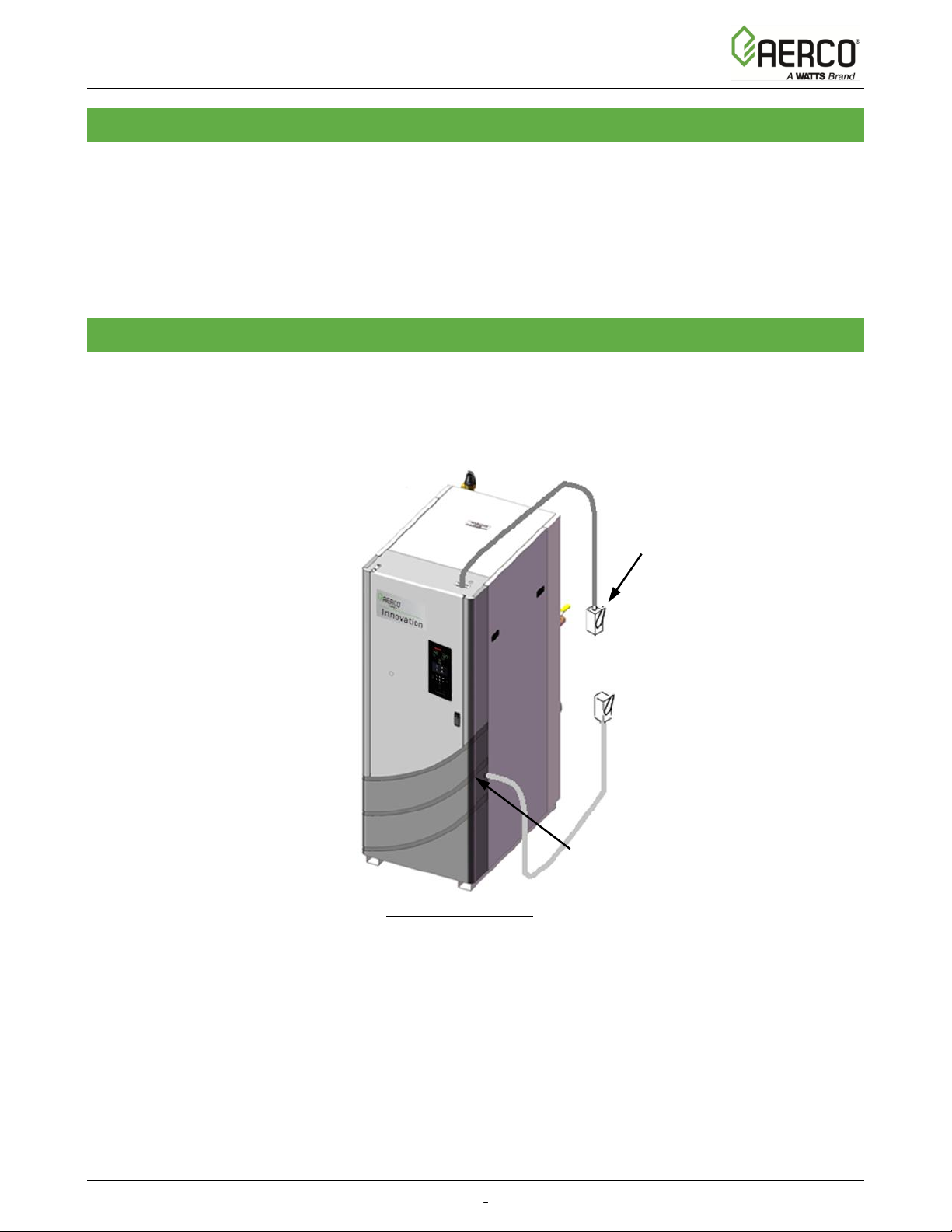
Refer to Figure 1 for typical Service Disconnect Switch location.
Figure 1. Service Switch Typical Location
The distribution block for field connection is located in the upper right of the control box (see Figure 2).
All copper wire must be connected to the terminal distribution block. 110 VAC is the minimum
allowable supply voltages to the unit. Lower voltages will result in increased wear and premature
failure of the blower motor. Wire size and type should be made per the National Electrical Code based
on length and load.
Figure 2 shows the location of the Power Box containing the terminal block connections. The Power
Box is accessed by removing the front panel door of the unit.
Service
Disconnect
Switch
Knock-Out for
alternate electrical
conduit to Service
Switch
INNOVATION-EDGE
 Loading...