

AERCO INN 1060N, INN 600N, INN 800N, INN 1350N Installation, Operation And Maintenance Manual
Disclaimer
The information contained in this manual is subject to change without notice
from AERCO International, Inc. AERCO makes no warranty of any kind with
respect to this material, including, but not limited to, implied warranties of
merchantability and fitness for a particular application. AERCO International is
not liable for errors appearing in this manual, not for incidental or consequential
damages occurring in connection with the furnishing, performance, or use of
these materials.
Heating and Hot Water Solutions
AERCO International, Inc. • 100 Oritani Drive • Blauvelt, NY 10913
USA: T: (845) 580-8000 • Toll Free: (800) 526-0288 • AERCO.com
Technical Support • (800) 526-0288 • Mon-Fri, 8 am - 5 pm EST
© 2019 AERCO
Innovation Water Heaters
With Edge [i] Controller
Installation, Operation and Maintenance Manual
OMM-0143_A • GF-216 • 9/6/2019
Applies to models:
• INN 600N
• INN 800N
• INN 1060N
• INN 1350N
Other documents for this product include:
• GF-5036 Gas Supply Design Guide
• GF-5056 Venting & Combustion Air Design Guide
• GF-5066 Electric Power Design Guide
• GF-5086 Sizing Guide
This manual applies to serial numbers:
G-19-2230 and above
U.S. Patent No. 9,243,848

Innovation - Edge [i] Installation, Operation, Maintenance Manual
CONTENTS
OMM-0143_A • GF-216 • 9/6/2019 Technical Support • (800) 526-0288 • Mon-Fri, 8 am - 5 pm EST Page 2 of 170
TABLE OF CONTENTS
FOREWORD ................................................................................................................... 7
CHAPTER 1. SAFETY PRECAUTIONS ..................................................................... 11
1.1 WARNINGS & CAUTIONS ..................................................................................................11
1.2 EMERGENCY SHUTDOWN ...............................................................................................12
1.3 PROLONGED SHUTDOWN ...............................................................................................12
1.4 FOR MASSACHUSETTS INSTALLATIONS .......................................................................13
CHAPTER 2. INSTALLATION .................................................................................... 15
2.1 INTRODUCTION.................................................................................................................15
2.2 RECEIVING THE UNIT .......................................................................................................15
2.3 UNPACKING .......................................................................................................................15
2.4 SITE PREPARATION .........................................................................................................16
2.4.1 Installation Clearances ..................................................................................................16
2.4.2 Setting the Unit .............................................................................................................17
2.5 WATER INLET AND OUTLET PIPING ................................................................................18
2.5.1 WHM Actuator-Controlled Ball Valve Installation ........................................................... 19
2.5.2 Automatic Float Vent Installation ...................................................................................20
2.6 TEST HOSE CONNECTION ...............................................................................................20
2.7 INTERNAL RECIRCULATION LOOP ..................................................................................21
2.8 PRESSURE & TEMPERATURE RELIEF VALVE INSTALLATION .....................................22
2.9 CONDENSATE DRAIN & PIPING .......................................................................................22
2.10 GAS SUPPLY PIPING ......................................................................................................24
2.10.1 Gas Supply Specifications. .........................................................................................24
2.10.2 Manual Gas Shutoff Valve ..........................................................................................25
2.10.3 External Gas Supply Regulator ...................................................................................25
2.11 AC ELECTRICAL POWER WIRING ..................................................................................26
2.11.1 Electrical Power Requirements ...................................................................................27
2.12 FIELD CONTROL WIRING ...............................................................................................28
2.12.1 OUTDOOR AIR IN Terminal .......................................................................................29
2.12.2 COMBUSTION AIR Terminals ....................................................................................29
2.12.3 O2 SENSOR Terminals ..............................................................................................29
2.12.4 SPARK SIGNAL Terminals .........................................................................................29
2.12.5 ANALOG IN Terminals ................................................................................................30
2.12.6 VALVE FEEDBACK Terminals ....................................................................................30
2.12.7 SHIELD Terminals ......................................................................................................30
2.12.8 ANALOG OUT Terminals ................................................................ ............................30
2.12.9 RS485 Comm Terminals .............................................................................................31
2.12.10 RS232 Comm Terminals ...........................................................................................31
2.12.11 VFD/BLOWER Terminals ..........................................................................................31
2.12.12 Interlock Terminals ....................................................................................................31
2.12.13 FAULT RELAY Terminals .........................................................................................31
2.12.14 AUX RELAY Terminals .............................................................................................32
2.13 FLUE GAS VENT INSTALLATION ....................................................................................32
2.14 COMBUSTION AIR ...........................................................................................................33
2.14.1 Combustion from Outside the Building ........................................................................33
2.14.2 Combustion Air from Inside the Building......................................................................33

Innovation - Edge [i] Installation, Operation, Maintenance Manual
CONTENTS
OMM-0143_A • GF-216 • 9/6/2019 Technical Support • (800) 526-0288 • Mon-Fri, 8 am - 5 pm EST Page 3 of 170
2.15 DUCTED COMBUSTION AIR ...........................................................................................34
CHAPTER 3. OPERATION ......................................................................................... 35
3.1 INTRODUCTION.................................................................................................................35
3.2 EDGE CONTROLLER DESCRIPTION ...............................................................................35
3.2.1 Touchscreen Button Functionality .................................................................................37
3.2.2 Logging In .....................................................................................................................38
3.3 MENU STRUCTURE ..........................................................................................................38
3.3.1 Unit Status Menu ................................................................ ..........................................39
3.3.2 Calibration Menu ...........................................................................................................40
3.3.3 Diagnostics Menu .........................................................................................................41
3.3.4 Main Menu → Advanced Setup ................................................................ ....................43
3.4 START SEQUENCE ...........................................................................................................51
3.5 START/STOP LEVELS .......................................................................................................54
CHAPTER 4. INITIAL START-UP ............................................................................... 55
4.1 INITIAL START-UP REQUIREMENTS ................................................................................55
4.2 TOOLS & INSTRUMENTs FOR COMBUSTION CALIBRATION .........................................55
4.2.1 Required Tools & Instrumentation .................................................................................56
4.2.2 Installing Gas Supply Manometer .................................................................................56
4.2.3 Accessing the Analyzer Probe Port ...............................................................................57
4.2.4 Connecting Multimeter to Flame Detector .....................................................................57
4.2.5 Recommendations for Temperature Calibration ............................................................58
4.2.6 Recommendations for WHM Operation .........................................................................58
4.3 COMBUSTION CALIBRATION ...........................................................................................59
4.4 REASSEMBLY ....................................................................................................................63
4.5 TEMPERATURE CONTROL CALIBRATION ......................................................................63
4.5.1 Setting the Outlet Water Temperature Setpoint .............................................................64
4.5.2 Minimum Load Adjustment ............................................................................................65
4.5.3 Maximum Load Adjustment ...........................................................................................65
4.6 OVER-TEMPERATURE LIMIT SWITCHES ........................................................................66
CHAPTER 5. SAFETY DEVICE TESTING .................................................................. 67
5.1 INTRODUCTION.................................................................................................................67
5.2 LOW GAS PRESSURE FAULT TEST .................................................................................67
5.3 HIGH GAS PRESSURE FAULT TEST ................................................................................68
5.4 LOW WATER LEVEL FAULT TEST ....................................................................................69
5.5 WATER TEMPERATURE FAULT TEST .............................................................................69
5.6 INTERLOCK TESTS ...........................................................................................................70
5.6.1 Remote Interlock ...........................................................................................................70
5.6.2 Delayed Interlock ..........................................................................................................71
5.7 FLAME FAULT TESTs ........................................................................................................71
5.8 AIR FLOW FAULT TESTS ..................................................................................................72
5.9 SSOV PROOF OF CLOSURE SWITCH .............................................................................74
5.10 PURGE SWITCH OPEN DURING PURGE .......................................................................75
5.11 IGNITION SWITCH OPEN DURING IGNITION.................................................................75
5.12 SAFETY PRESSURE RELIEF VALVE TEST ....................................................................76
CHAPTER 6. MAINTENANCE .................................................................................... 77

Innovation - Edge [i] Installation, Operation, Maintenance Manual
CONTENTS
OMM-0143_A • GF-216 • 9/6/2019 Technical Support • (800) 526-0288 • Mon-Fri, 8 am - 5 pm EST Page 4 of 170
6.1 MAINTENANCE SCHEDULE ..............................................................................................77
6.2 Water Quality Guideline ......................................................................................................78
6.3 IGNITER-INJECTOR ..........................................................................................................78
6.4 FLAME DETECTOR ...........................................................................................................81
6.5 COMBUSTION CALIBRATION ...........................................................................................81
6.6 SAFETY DEVICE TESTING ...............................................................................................81
6.7 FIRESIDE INSPECTION .....................................................................................................82
6.8 WATERSIDE INSPECTION AND CLEANING .....................................................................86
6.8.1 Waterside Inspection-Cleaning Schedule ................................ ......................................86
6.8.2 Waterside Inspection ....................................................................................................87
6.8.3 Waterside Heat Exchanger Cleaning ............................................................................88
6.9 CONDENSATE DRAIN TRAP .............................................................................................90
6.10 AIR FILTER REPLACEMENT ...........................................................................................91
6.11 LOW WATER CUTOFF (LWCO) CAPACITOR INTEGRITY TEST ...................................92
6.11.1 Low Water Cutoff (LWCO) - Capacitor Electrical Short Test........................................92
6.11.2 Low Water Cutoff (LWCO) - Standard Test .................................................................94
6.12 SHUTTING THE WATER HEATER DOWN FOR AN EXTENDED PERIOD OF TIME ......94
6.13 PLACING THE UNIT BACK IN SERVICE AFTER A PROLONGED SHUTDOWN ............94
6.14 SPARK MONITOR (AC CURRENT TRANSDUCER) ........................................................95
CHAPTER 7. TROUBLESHOOTING GUIDE .............................................................. 97
7.1 INTRODUCTION.................................................................................................................97
7.2 ADDITIONAL FAULTS WITHOUT SPECIFIC FAULT MESSAGES .................................. 109
CHAPTER 8. WATER HEATER MANAGEMENT ..................................................... 111
8.1 GENERAL DESCRIPTION ................................................................................................ 111
8.2 WHM PRINCIPLES OF OPERATION ............................................................................... 112
8.3 NEW AERCO WHM FEATURES ...................................................................................... 112
8.3.1 Valve Feedback .......................................................................................................... 112
8.3.2 Valve Supervisor ......................................................................................................... 112
8.3.3 Valve Control .............................................................................................................. 112
8.3.4 Modbus Header Sensor ................................................................ .............................. 113
8.3.5 Temperature Sensor Calibration ................................................................................. 113
8.3.6 Manual Mode Password Required .............................................................................. 113
8.3.7 Auto-Manager Transfer ............................................................................................... 114
8.3.8 Run Hours and Run Cycles ......................................................................................... 114
8.3.9 High Temperature Governor ....................................................................................... 114
8.4 WHM STATUS DISPLAYS ................................................................................................ 115
8.5 WATER HEATER MANAGEMENT ALTERNATING STATUS DISPLAYS......................... 115
8.6 WHM Parameters .............................................................................................................. 116
8.7 WHM HARDWARE INSTALLATION & SET-UP INSTRUCTIONS .................................... 122
8.7.1 Installation Notes ................................................................ ........................................ 123
8.7.2 Hardware Installation .................................................................................................. 123
8.7.3 WHM Modbus Network Wiring .................................................................................... 124
8.7.4 Control and Power Wiring ........................................................................................... 125
8.8 WHM PROGRAMMING & START-UP .............................................................................. 129
8.9 TROUBLESHOOTING ...................................................................................................... 131
8.10 SEQUENCING VALVE DESCRIPTION & OPERATION ................................................. 132

Innovation - Edge [i] Installation, Operation, Maintenance Manual
CONTENTS
OMM-0143_A • GF-216 • 9/6/2019 Technical Support • (800) 526-0288 • Mon-Fri, 8 am - 5 pm EST Page 5 of 170
8.10.1 Sequencing Valve Description .................................................................................. 132
8.10.2 Sequencing Valve Operating Characteristics ............................................................ 134
APPENDIX A – Startup, Status and Fault Messages .............................................................. 135
APPENDIX B – Temperature Sensor Resistance/Voltage Chart ............................................. 136
APPENDIX D – Dimensional Drawings ................................................................................... 137
APPENDIX E – Parts List Drawings ........................................................................................ 139
APPENDIX F – Piping Drawings ............................................................................................. 151
APPENDIX G – Edge [i] Controller Views ............................................................................... 161
APPENDIX H – Wiring Diagrams ............................................................................................ 163
APPENDIX I – Recommended Spares .................................................................................... 167

Innovation - Edge [i] Installation, Operation, Maintenance Manual
CONTENTS
OMM-0143_A • GF-216 • 9/6/2019 Technical Support • (800) 526-0288 • Mon-Fri, 8 am - 5 pm EST Page 6 of 170
(This Page Is Intentionally Blank)
Innovation - Edge [i] Installation, Operation, Maintenance Manual
FORWARD
OMM-0143_A • GF-216 • 9/6/2019 Technical Support • (800) 526-0288 • Mon-Fri, 8 am - 5 pm EST Page 7 of 170
FOREWORD
The AERCO Innovation Series Potable Water Heaters are tankless modulating units which
represent a true industry advance that meets the needs of today's energy efficiency and
environmental concerns. Innovation’s compact size and robust venting capabilities allow
maximum installation flexibility. The Innovation Series Heaters, with their load tracking controls
can modulate up to 30:1 turn down ratio to match the system demand and yield high thermal
efficiencies.
Innovation Water Heaters are available in four (4) different sizes ranging from 625,000 BTU/Hr.
(183.2 kW) input to 1,350,000 BTU/Hr. (395.6 kW) input, all with Natural Gas gas trains. The
available models are listed below.
All Innovation models include Water Heater Management (WHM) software, which is built into the
unit’s Edge Controller. When the heater is ordered with a Sequencing Valve (SV), up to 16
Innovation Water Heaters can be controlled by the WHM system utilizing RS485 Modbus
protocol. Units can be ordered with or without Sequencing Valves.
When installed and operated on natural gas in accordance with this Instruction Manual, the
Innovation Series models covered herein comply with the NOx emission standards outlined in:
1. South Coast Air Quality Management District (SCAQMD), Rule 1146.2
2. Texas Commission on Environmental Quality (TCEQ), Title 30, Chapter 117,
Rule 117.465
Whether used in singular or modular arrangements, Innovation Water Heaters offer the
maximum flexibility in venting with minimum installation space requirements. Innovation’s
advanced electronic controls offer simplified integration with today’s Energy Management
Systems.
For service or parts, contact your local sales representative or AERCO International, Inc.
IMPORTANT!
Unless otherwise specified, the descriptions and procedures provided in this Installation,
Operation & Maintenance Manual apply to all Innovation Series Water Heaters.
TABLE F1: INNOVATION POTABLE WATER HEATER MODELS
Models
Description
Shipping
Weight
INN 600N
Innovation Potable Water Heater, 625,000 BTU/Hr. (183.2 kW) Input
1,060 lbs.
(480.8 kg.)
INN 800N
Innovation Potable Water Heater, 800,000 BTU/Hr. (234.5 kW) Input
1,080 lbs.
(489.9 kg.)
INN 1060N
Innovation Potable Water Heater, 1,060,000 BTU/Hr. (310.7 kW) Input
1,100 lbs.
(499.0 kg.)
INN 1350N
Innovation Potable Water Heater, 1,400,000 BTU/Hr. (410.3 kW) Input
1,150 lbs.
(521.6 kg.)

Innovation - Edge [i] Installation, Operation, Maintenance Manual
FORWARD
OMM-0143_A • GF-216 • 9/6/2019 Technical Support • (800) 526-0288 • Mon-Fri, 8 am - 5 pm EST Page 8 of 170
Phrases, abbreviations and acronyms used in this manual are listed in the following table:
AERCO Technical Terminology Meanings
TERMINOLOGY
MEANING
A (Amp)
Ampere
ADDR
Address
AGND
Analog Ground
ALRM
Alarm
ANSI
American National Standards Institute
ASME
American Society of Mechanical Engineers
AUX
Auxiliary
BAS
Building Automation System, often used interchangeably with EMS
(see below)
Baud Rate
Symbol rate, or simply the number of distinct symbol changes
(signaling events) transmitted per second. It is not equal to bits per
second, unless each symbol is 1 bit long.
BLDG (Bldg)
Building
BTU
British Thermal Unit. A unit of energy approximately equal to the heat
required to raise 1 pound (0.45 kg) of water 1° F (0.55 ° C).
BTU/Hr.
BTUs per Hour (1 BTU/Hr. = 0.29 W)
Edge Controller
A control system developed by AERCO and used in all Benchmark,
Innovation and KC1000 Series product lines.
CO
Carbon Monoxide
COMM (Comm)
Communication
Cal.
Calibration
CNTL
Control
CPU
Central Processing Unit
DBB
Double Block and Bleed, a gas trains containing 2 Safety Shutoff
Valves (SSOVs) and a solenoid operated vent valve.
DIP
Dual In-Line Package, a type of switch
EMS
Energy Management System; often used interchangeably with BAS
FM
Factory Mutual. Used to define gas trains.
FRU
Field Replacement Unit
GF-xxxx
Gas Fired (an AERCO document numbering system)
GND
Ground
GPH
Gallons per Hour
HX
Heat Exchanger
Hz
Hertz (Cycles Per Second)
I.D.
Inside Diameter
IGN
Ignition
IGST Board
Ignition/Stepper Board, contained in Edge Controller

Innovation - Edge [i] Installation, Operation, Maintenance Manual
FORWARD
OMM-0143_A • GF-216 • 9/6/2019 Technical Support • (800) 526-0288 • Mon-Fri, 8 am - 5 pm EST Page 9 of 170
AERCO Technical Terminology Meanings
TERMINOLOGY
MEANING
INN
Innovation Water Heater
I/O
Input/Output
I/O Box
Input/Output (I/O) Box currently used on Benchmark, Innovation and
KC1000 Series products
IP
Internet Protocol
IRI
Industrial Risk Insurers. Used to define gas trains containing two
SSOVs and a solenoid operated vent valve (See DBB above)
ISO
International Organization for Standardization
Lbs.
Pounds (1 lb. = 0.45 kg)
LED
Light Emitting Diode
LN
Low Nitrogen Oxide
MA (mA)
Milliampere (1 thousandth of an ampere)
MAX (Max)
Maximum
MIN (Min)
Minimum
Modbus®
A serial, half-duplex data transmission protocol developed by AEG
Modicon
NC (N.C.)
Normally Closed
NO (N.O.)
Normally Open
NOx
Nitrogen Oxide
NPT
National Pipe Thread
O2
Oxygen
O.D.
Outside Diameter
OMM
Operation and Maintenance Manual
OnAER
AERCO’s on-line remote system monitoring system
PCB
Printed Circuit Board
PMC Board
Primary Micro-Controller (PMC) board, contained in the Edge
Controller
P/N
Part Number
PPM
Parts per Million
PSI
Pounds per Square Inch (1 PSI = 6.89 kPa)
PTP
Point-to-Point (usually over RS232 networks)
P&T
Pressure and Temperature
ProtoNode
Hardware interface between BAS and a boiler or water heater
PVC
Poly Vinyl Chloride, a common synthetic plastic
PWM
Pulse Width Modulation
RES.
Resistive
RS232
(or EIA-232)
A standard for serial, full-duplex (FDX) transmission of data based on
the RS232 Standard

Innovation - Edge [i] Installation, Operation, Maintenance Manual
FORWARD
OMM-0143_A • GF-216 • 9/6/2019 Technical Support • (800) 526-0288 • Mon-Fri, 8 am - 5 pm EST Page 10 of 170
AERCO Technical Terminology Meanings
TERMINOLOGY
MEANING
RS422
(or EIA-422)
A standard for serial, full-duplex (FDX) transmission of data based on
the RS422 Standard
RS485
(or EIA-485)
A standard for serial, half-duplex (HDX) transmission of data based on
the RS485 Standard
SETPT (Setpt)
Setpoint Temperature
SHLD (Shld)
Shield
SPDT
Single Pole Double Throw, a type of switch
SSD
Client to Client programming
SSOV
Safety Shut Off Valve
SV
Sequencing Valve (Used with Water Heater Management (WHM)
system)
TEMP (Temp)
Temperature
Terminating Resistor
A resistor placed at each end of a daisy-chain or multi-drop network in
order to prevent reflections that may cause invalid data in the
communication
Tip-N-Tell
A device that indicates if a package was tipped during shipping
UL
A business that tests and validates products
VAC
Volts, Alternating Current
VDC
Volts, Direct Current
VFD
Vacuum Fluorescent Display, also Variable Frequency Drive
W
Watt
WHM
Water Heater Management
W.C.
Water Column, a unit of pressure (1-inch W.C. = 249 Pa)
µA
Micro amp (1 millionth of an ampere)

Innovation - Edge [i] Installation, Operation, Maintenance Manual
CHAPTER 1 – SAFETY PRECAUTIONS
OMM-0143_A • GF-216 • 9/6/2019 Technical Support • (800) 526-0288 • Mon-Fri, 8 am - 5 pm EST Page 11 of 170
CHAPTER 1. SAFETY PRECAUTIONS
1.1 WARNINGS & CAUTIONS
Installers and operating personnel MUST, at all times, observe all safety regulations. The
following warnings and cautions are general and must be given the same attention as specific
precautions included in these instructions. In addition to all the requirements included in this
AERCO Instruction Manual, the installation of units MUST conform with local building codes, or,
in the absence of local codes, ANSI Z223.1 (National Fuel Gas Code Publication No. NFPA-54)
for gas-fired heaters and ANSI/NFPASB for LP gas-fired heaters. Where applicable, the
equipment shall be installed in accordance with the current Installation Code for Gas Burning
Appliances and Equipment, CSA B149.1, and applicable Provincial regulations for the class;
which should be carefully followed in all cases. Authorities having jurisdiction should be
consulted before installations are made.
See Section 1.4, below, for information on installations within the Commonwealth of
Massachusetts.
IMPORTANT!
This Instruction Manual is an integral part of the product and must be maintained in legible
condition. It must be given to the user by the installer and kept in a safe place for future
reference.
IMPORTANT!
Read the following restrictions prior to installing the water heater:
1. The water heater can only be used for applications where the chlorine concentrations do
not exceed 4 mg/L, which is the Environmental Protection Agency limit for chlorine
concentrations in drinking water.
2. Do Not use this heater for a pool heating application.
WARNINGS!
• Do not use matches, candles, flames, or other sources of ignition to check for gas leaks.
• Fluids under pressure may cause injury to personnel or damage to equipment when
released. Be sure to shut off all incoming and outgoing water shutoff valves and carefully
decrease all trapped pressures to zero before performing maintenance.
• ELECTRICAL CURRENT OF 110 (OR 220 VOLTS FOR INTERNATIONAL MODELS)
AND 24 VOLTS AC MAY BE USED IN THIS EQUIPMENT. The unit’s power box cover
(located behind the front panel door) must therefore be installed at all times, except
during maintenance and servicing.
• A switch must be installed on the electrical supply line of the unit, in an easily accessible
position to quickly and safely disconnect electrical service. Do not affix switch to unit
sheet metal enclosures.
Innovation - Edge [i] Installation, Operation, Maintenance Manual
CHAPTER 1 – SAFETY PRECAUTIONS
OMM-0143_A • GF-216 • 9/6/2019 Technical Support • (800) 526-0288 • Mon-Fri, 8 am - 5 pm EST Page 12 of 170
CAUTION!
• Many soaps used for gas pipe leak testing are corrosive to metals. The piping must be
rinsed thoroughly with clean water after leak checks have been completed.
• DO NOT use this heater if any part has been under water. Call a qualified service
technician to inspect and replace any part that has been under water.
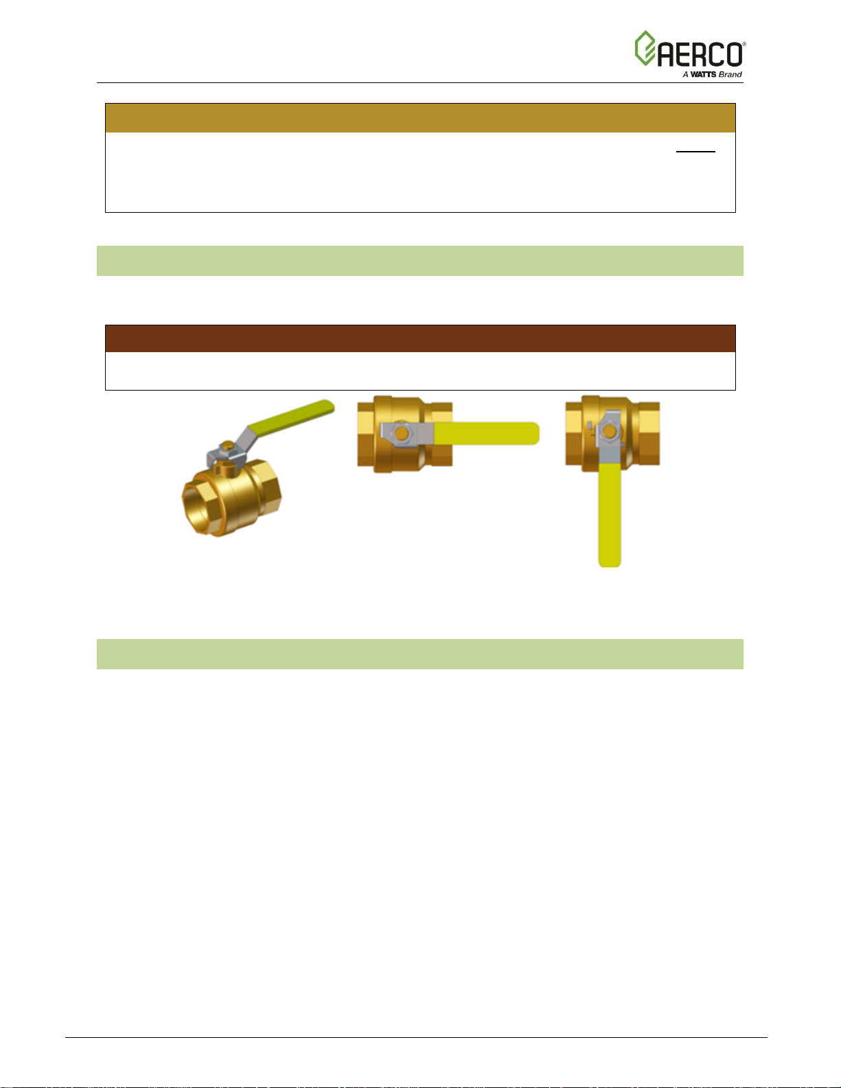
1.2 EMERGENCY SHUTDOWN
If overheating occurs or the gas supply fails to shut off, close the manual gas shutoff valve
(Figure 1-1) located external to the unit.
IMPORTANT!
The Installer must identify and indicate the location of the emergency shutdown manual gas
valve to operating personnel.
Figure 1.2: Manual Gas Shutoff Valve
1.3 PROLONGED SHUTDOWN
After prolonged shutdown, it is recommended that the initial startup procedures in Chapter 4
and the safety device test procedures in Chapter 5 of this manual be performed to verify all
system-operating parameters. If there is an emergency, turn off the electrical power supply to
the unit and close the manual gas valve located upstream of the unit. The installer must identify
the emergency shut-off device.
VALVE OPEN
VALVE CLOSED

Innovation - Edge [i] Installation, Operation, Maintenance Manual
CHAPTER 1 – SAFETY PRECAUTIONS
OMM-0143_A • GF-216 • 9/6/2019 Technical Support • (800) 526-0288 • Mon-Fri, 8 am - 5 pm EST Page 13 of 170
1.4 FOR MASSACHUSETTS INSTALLATIONS
Water heater Installations within the Commonwealth of Massachusetts must conform to the
following requirements:
• Heater must be installed by a plumber or a gas fitter who is licensed within the
Commonwealth of Massachusetts.
• Prior to unit operation, the complete gas train and all connections must be leak
tested using a non-corrosive soap.
• The vent termination must be located a minimum of 4 feet (1.2m) above grade
level. If side-wall venting is used, the installation must conform to the following
requirements extracted from 248 CMR 5.08 (2):
(a) For all side wall horizontally vented gas fueled equipment installed in every dwelling,
building or structure used in whole or in part for residential purposes, including those owned or
operated by the Commonwealth and where the side wall exhaust vent termination is less than
seven (7) feet (2.1m) above finished grade in the area of the venting, including but not limited to
decks and porches, the following requirements shall be satisfied:
1. INSTALLATION OF CARBON MONOXIDE DETECTORS. At the time of installation of
the side wall horizontal vented gas fueled equipment, the installing plumber or gasfitter shall
observe that a hard-wired carbon monoxide detector with an alarm and battery back-up is
installed on the floor level where the gas equipment is to be installed. In addition, the
installing plumber or gasfitter shall observe that a battery operated or hard-wired carbon
monoxide detector with an alarm is installed on each additional level of the dwelling, building
or structure served by the side wall horizontal vented gas fueled equipment. It shall be the
responsibility of the property owner to secure the services of qualified licensed professionals
for the installation of hard-wired carbon monoxide detectors.
a. In the event that the side wall horizontally vented gas fueled equipment is installed in
a crawl space or an attic, the hard-wired carbon monoxide detector with alarm and
battery back-up may be installed on the next adjacent floor level.
b. In the event that the requirements of this subdivision cannot be met at the time of
completion of installation, the owner shall have a period of thirty (30) days to comply with
the above requirements; provided, however, that during said thirty (30) day period, a
battery-operated carbon monoxide detector with an alarm shall be installed.
2. APPROVED CARBON MONOXIDE DETECTORS. Each carbon monoxide detector as
required in accordance with the above provisions shall comply with NFPA 720 and be
ANSI/UL 2034 listed and IAS certified.
3. SIGNAGE. A metal or plastic identification plate shall be permanently mounted to the
exterior of the building at a minimum height of eight (8) feet (2.4m) above grade directly in
line with the exhaust vent terminal for the horizontally vented gas fueled heating appliance
or equipment. The sign shall read, in print size no less than one-half (1/2) inch in size, "GAS
VENT DIRECTLY BELOW. KEEP CLEAR OF ALL OBSTRUCTIONS".
4. INSPECTION. The state or local gas inspector of the side wall horizontally vented gas
fueled equipment shall not approve the installation unless, upon inspection, the inspector
observes carbon monoxide detectors and signage installed in accordance with the
provisions of 248 CMR 5.08(2)(a)1 through 4.
(b) EXEMPTIONS: The following equipment is exempt from 248 CMR 5.08(2)(a)1 through 4:

Innovation - Edge [i] Installation, Operation, Maintenance Manual
CHAPTER 1 – SAFETY PRECAUTIONS
OMM-0143_A • GF-216 • 9/6/2019 Technical Support • (800) 526-0288 • Mon-Fri, 8 am - 5 pm EST Page 14 of 170
1. The equipment listed in Chapter 10 entitled "Equipment Not Required To Be Vented" in
the most current edition of NFPA 54 as adopted by the Board; and
2. Product Approved side wall horizontally vented gas fueled equipment installed in a room
or structure separate from the dwelling, building or structure used in whole or in part for
residential purposes.
(c) MANUFACTURER REQUIREMENTS - GAS EQUIPMENT VENTING SYSTEM
PROVIDED. When the manufacturer of Product Approved side wall horizontally vented gas
equipment provides a venting system design or venting system components with the equipment,
the instructions provided by the manufacturer for installation of the equipment and the venting
system shall include:
1. Detailed instructions for the installation of the venting system design or the venting
system components; and
2. A complete parts list for the venting system design or venting system.
(d) MANUFACTURER REQUIREMENTS - GAS EQUIPMENT VENTING SYSTEM NOT
PROVIDED. When the manufacturer of a Product Approved side wall horizontally vented gas
fueled equipment does not provide the parts for venting the flue gases, but identifies "special
venting systems", the following requirements shall be satisfied by the manufacturer:
1. The referenced "special venting system" instructions shall be included with the appliance
or equipment installation instructions; and
2. The "special venting systems" shall be Product Approved by the Board, and the
instructions for that system shall include a parts list and detailed installation instructions.
(e) A copy of all installation instructions for all Product Approved side wall horizontally vented
gas fueled equipment, all venting instructions, all parts lists for venting instructions, and/or all
venting design instructions shall remain with the appliance or equipment at the completion of the
installation.
______________________________________
[End of Extracted Information From 248 CMR 5.08 (2)]
Innovation - Edge [i] Installation, Operation, Maintenance Manual
CHAPTER 2 – INSTALLATION
OMM-0143_A • GF-216 • 9/6/2019 Technical Support • (800) 526-0288 • Mon-Fri, 8 am - 5 pm EST Page 15 of 170
CHAPTER 2. INSTALLATION
2.1 INTRODUCTION
This Chapter provides the descriptions and procedures necessary to unpack, inspect and install
AERCO Innovation Water Heaters.
2.2 RECEIVING THE UNIT
Each Innovation Water Heating System is shipped as a single crated unit. The shipping weight
is shown in Table F1 in the Forward to this manual. The unit must be moved with the proper
rigging equipment for safety and to avoid equipment damage. The unit should be completely
inspected for evidence of shipping damage and shipment completeness at the time of receipt
from the carrier and before the bill of lading is signed.
NOTE:
AERCO is not responsible for lost or damaged freight. Each unit has a Tip-N-Tell indicator
on the outside of the shipping container, which indicates if the unit has been turned on its
side during shipment. If the Tip-N-Tell indicator is tripped, do not sign for the shipment. Note
the information on the carrier’s paperwork and request a freight claim and inspection by a
claims adjuster before proceeding. Any other visual damage to the packaging materials
should also be made clear to the delivering carrier.
2.3 UNPACKING
Carefully unpack the unit taking care not to damage the unit’s enclosure when cutting away
packaging materials
After unpacking, closely inspect the unit to make sure there is no evidence of damage not
indicated by the Tip-N-Tell indicator. Notify the freight carrier immediately if any damage is
detected.
Each unit is shipped with the accessory kit ordered with the unit. The specific parts you receive
depend on which accessory kit was ordered, but all kits include the following parts:
• Condensate Drain Trap (P/N 99259)
• Automatic Float Vent (P/N 99285) and Service Check Valve (P/N 99286)
• Ignitor Kit (P/N 58023)
• Flame Rod Kit (P/N 24356-2)
If the Innovation Water Heater is equipped for use with the AERCO Water Heater Management
(WHM) system, an actuator-controlled ball valve will also be included with the unit.
If optional accessories were ordered, they may be packed within the unit’s shipping container,
factory installed on the unit, or packed and shipped in a separate container. Any standard or
optional accessories shipped loose should be identified and stored in a safe place until ready for
installation or use.
Innovation - Edge [i] Installation, Operation, Maintenance Manual
CHAPTER 2 – INSTALLATION
OMM-0143_A • GF-216 • 9/6/2019 Technical Support • (800) 526-0288 • Mon-Fri, 8 am - 5 pm EST Page 16 of 170
2.4 SITE PREPARATION
Ensure that the site selected for installation of the Innovation Water Heater includes:
• Access to AC Input Power at either:
o 110 VAC, Single-Phase, 60 Hz @ 20 Amps
o 220 VAC, Single-Phase, 50/60 Hz @ 20 Amps – International Models only
• Access to a Natural Gas line with a minimum pressure of 4 inches W.C. (1.0 kPa) with
the unit operating at maximum capacity.
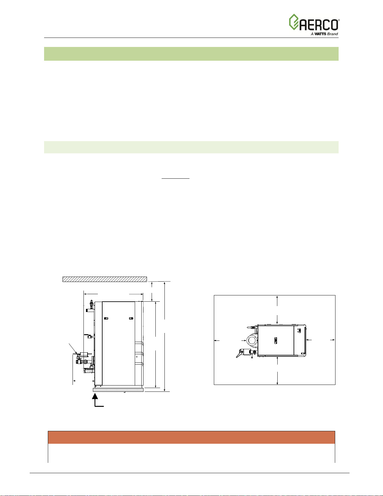
2.4.1 Installation Clearances
All Innovation models are packaged in enclosures having identical exterior dimensions. The unit
must be installed with the prescribed clearances for service as shown in Figure 2.4.1-1 (shown
with optional Sequencing Valve). The minimum clearance dimensions, required by AERCO, are
listed below. However, if Local Building Codes require additional clearances, these codes shall
supersede AERCO’s requirements. Minimum acceptable clearances required are as follows:
Sides: 24 inches (0.61 m)
Front: 24 inches (0.61 m)
Rear: 30 inches (0.76 m)
Top: 18 inches (0.46 m)
All gas piping, water piping and electrical conduit or cable must be arranged so that they do not
interfere with the removal of any panels, or inhibit service or maintenance of the unit. Zero side
clearance is also permissible.
50.9"
18"
97.25"
75.25"
18.6"
SEQUENCING
VALVE
30"
24"
24"
24"
4" HIGH PAD
Figure 2.4.1-1: Innovation Water Heater Clearances
WARNING!
KEEP THE UNIT AREA CLEAR AND FREE FROM ALL COMBUSTIBLE MATERIALS AND
FLAMMABLE VAPORS OR LIQUIDS.
24” (0.61m)
24” (0.61m)
24”
(0.61m)
30”
(0.76 m)
97.25”
(2.47m)
75.26”
(1.91m)
18.6”
(47cm)
50.87”
18” (0.46m)
4” to 6” (10.2 to 15.2 cm) thick concrete housekeeping pad. Ensure that
this pad is level and does NOT extend under the condensate assembly.
Innovation - Edge [i] Installation, Operation, Maintenance Manual
CHAPTER 2 – INSTALLATION
OMM-0143_A • GF-216 • 9/6/2019 Technical Support • (800) 526-0288 • Mon-Fri, 8 am - 5 pm EST Page 17 of 170
CAUTION!
While packaged in the shipping container, the unit must be moved by pallet jack or forklift
from the FRONT ONLY.
FOR MASSACHUSETTS ONLY
For Massachusetts installations, the unit must be installed by a plumber or gas-fitter who is
licensed within the Commonwealth of Massachusetts. In addition, the installation must
comply with all requirements specified in Chapter 1, Section 1.4, above.
2.4.2 Setting the Unit
The unit must be installed on a 4 to 6-inch (10.2 to 15.2 cm) level housekeeping pad to avoid
base corrosion. Two lifting lugs are provided with the unit and are wire-tied to the top of the heat
exchanger. The top sheet metal cover of the unit must first be removed and the lifting lugs must
be installed as shown in Figure 2.4.2. USE THESE TWO LUGS TO LIFT AND MOVE THE
UNIT. Remove the top panel from the unit to provide access to the lifting lugs. Remove the four
(4) lag screws securing the unit to the shipping skid. Lift the unit off the shipping skid and
position it on the 4 to 6-inch (10.2 to 15.2 cm) housekeeping concrete pad (required) in the
desired location.
In multiple unit installations, it is important to plan the position of each unit in advance. Sufficient
space for piping connections and future service/maintenance requirements must also be taken
into consideration. All piping must include ample provisions for expansion.
Figure 2.4.2: Partial Top View Showing Installed Lifting Lugs
LIFTING LUGS
Innovation - Edge [i] Installation, Operation, Maintenance Manual
CHAPTER 2 – INSTALLATION
OMM-0143_A • GF-216 • 9/6/2019 Technical Support • (800) 526-0288 • Mon-Fri, 8 am - 5 pm EST Page 18 of 170
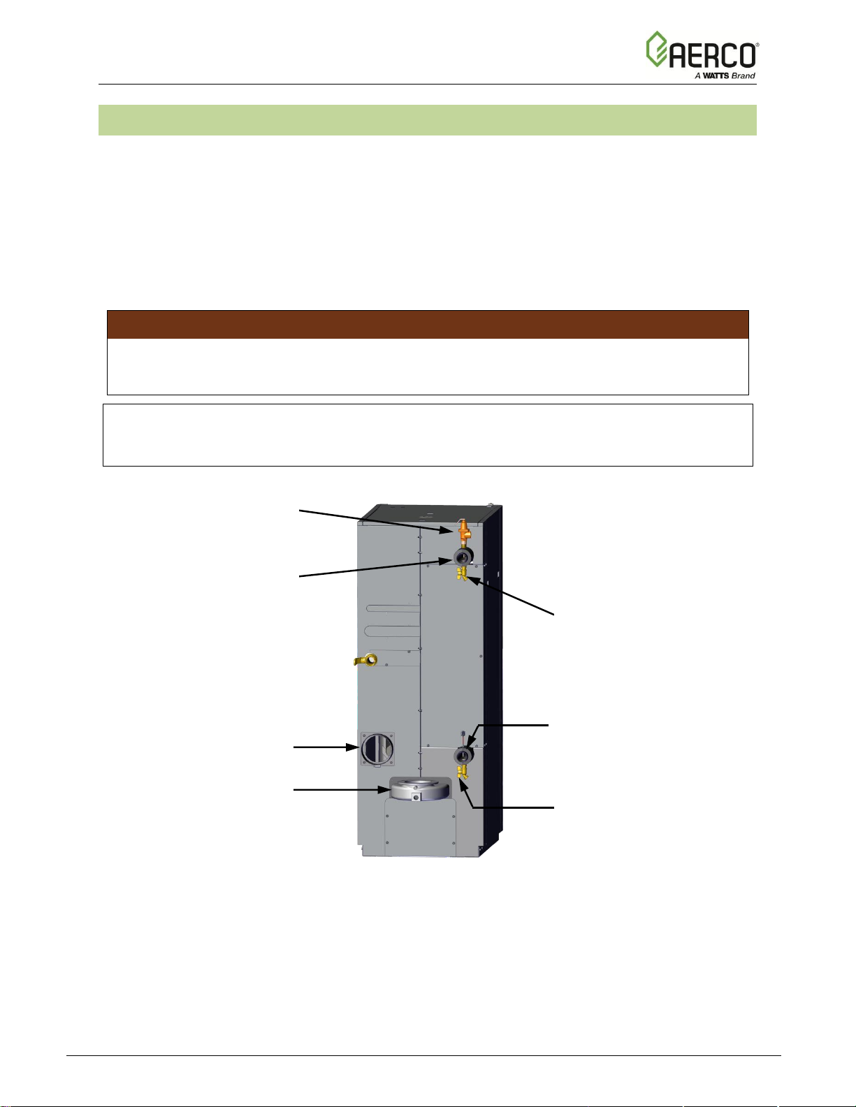
2.5 WATER INLET AND OUTLET PIPING
The locations of the 2" (5.08 cm) NPT cold water inlet and hot water outlet piping connections
are shown in Figure 2.5. Flow rates through the unit are limited to 50 gallons (189 Liters) per
minute continuous.
Shut-off valves and union connections must be installed in the inlet and outlet lines for
maintenance. The use of dielectric unions is recommended.
When connecting the hot water outlet and cold-water inlet to building piping, first make sure the
threads are thoroughly clean. AERCO recommends using Teflon tape followed by RectorSeal®
T+2 when plumbing the inlet and outlet water connections.
IMPORTANT!
If the Innovation Water Heater is equipped for use with the Edge Controller’s Water Heater
Management (WHM) system, then an actuator-controlled ball valve will be included with the
shipment. Refer to Section 2.5.1 for installation instructions prior to connecting inlet piping.
NOTE:
All piping must be arranged so that it does not interfere with the removal of any covers,
inhibit service or maintenance, or prevent access between the unit and walls, or another unit.
Figure 2.5: Water Inlet & Outlet Locations
P&T RELIEF
VALVE
COLD WATER INLET
2” NPT
LOWER DRAIN
VALVE
EXHAUST MANIFOLD
AIR INLET
HOT WATER OUTLET
2” NPT
UPPER DRAIN
VALVE
Innovation - Edge [i] Installation, Operation, Maintenance Manual
CHAPTER 2 – INSTALLATION
OMM-0143_A • GF-216 • 9/6/2019 Technical Support • (800) 526-0288 • Mon-Fri, 8 am - 5 pm EST Page 19 of 170
2.5.1 WHM Actuator-Controlled Ball Valve Installation
If the Innovation Water Heater was ordered for use with the Water Heater Management (WHM)
system and the actuator-controlled ball valve is not already installed on the unit, as shown in
Figure 2.5.1, it will be packed separately within the shipping container.
NOTE:
AERCO requires use of WHM sequencing valves in a multi-unit configuration. See Section
4.2.6: Recommendations for WHM Operation for more information.
If installation is required, proceed as follows:
WHM BALL VALVE INSTALLATION Instructions
3. Remove the ball valve from its stowed location within the shipping container.
4. Attached the valve to the cold-water inlet of the unit using the pipe union and nipple
provided.
5. Ensure that the valve is positioned with the actuator enclosure position as shown in Figure
2.5.1.
6. AERCO recommends that another pipe nipple and union be attached to the valve inlet prior
to connecting the cold-water supply piping.
7. Tighten all pipe connections after the valve is properly positioned.
8. Connect the 4-pin Molex connector on the valve to the mating connector on the Innovation
harness at the rear of the unit.
9. This completes the actuator-controlled ball valve installation.
Figure 2.5.1: Innovation Water Heater Equipped with Sequencing Valve
HEATER DRAIN VALVE
2” NPT UNION
BALL VALVE
WITH ACTUATOR
2” NPT
Innovation - Edge [i] Installation, Operation, Maintenance Manual
CHAPTER 2 – INSTALLATION
OMM-0143_A • GF-216 • 9/6/2019 Technical Support • (800) 526-0288 • Mon-Fri, 8 am - 5 pm EST Page 20 of 170
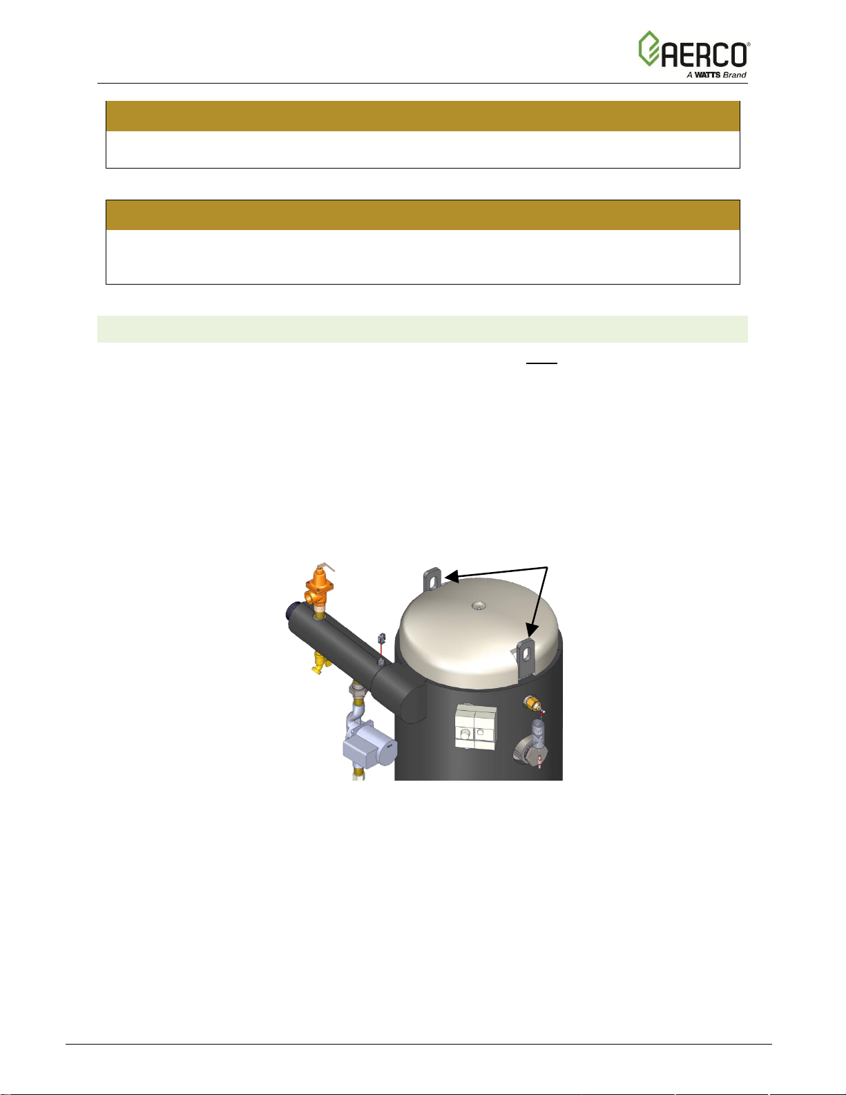
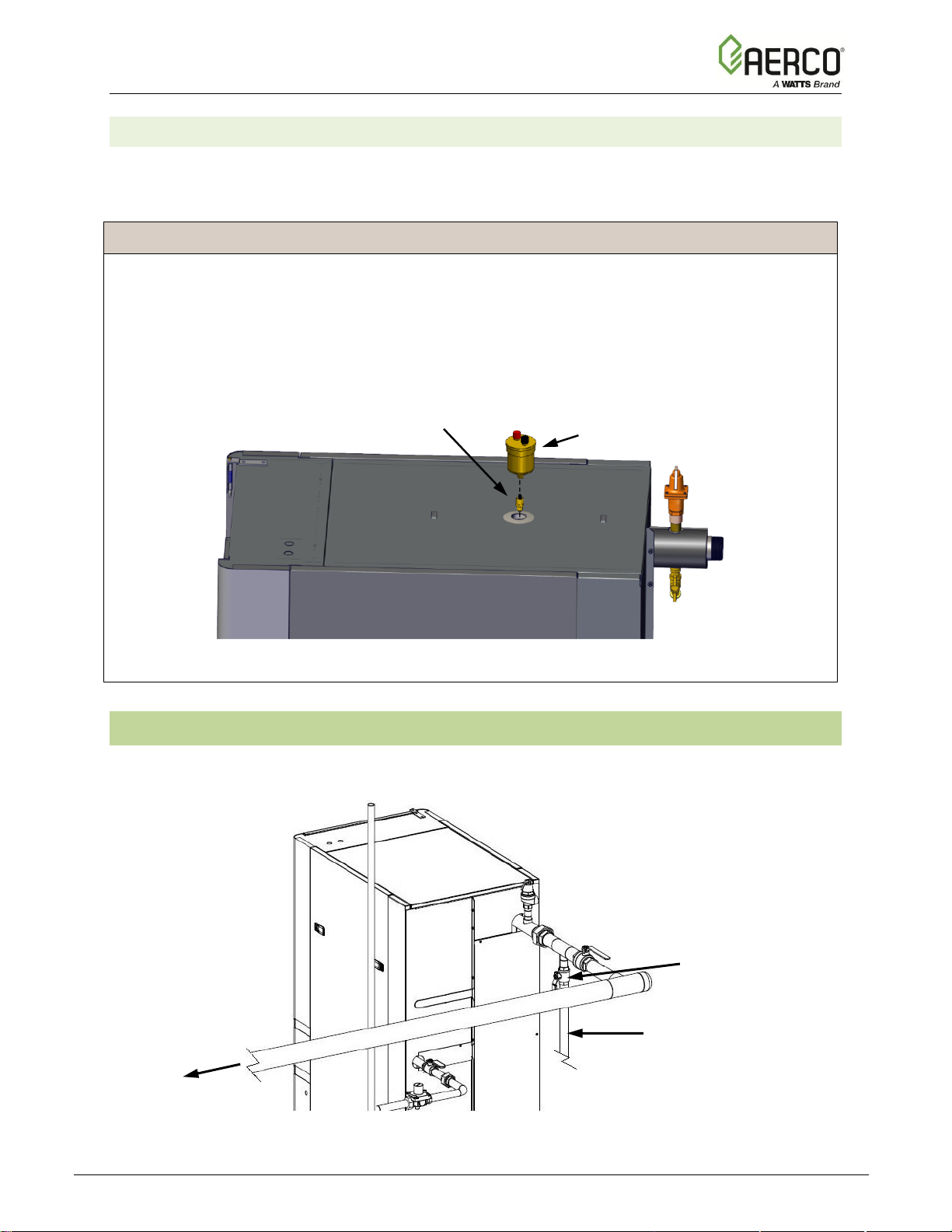
2.5.2 Automatic Float Vent Installation
All Innovation Water Heaters require an Automatic Float Vent connected to a Safety Check
valve. Both must be installed on all units, on the top of the heat exchanger dome, as shown
below. Both valves are included in the Accessory Kit shipped with the unit.
AUTOMATIC FLOAT VENT Instructions
1. All units are shipped with a hex nut in the center of the heat exchanger dome, which
protrudes through a hole in the center of the top enclosure panel. Remove this hex nut.
2. Fasten the Automatic Float Vent (P/N 99285) to top of the Service Check valve(P/N
99268), as shown below. Leave the red and black plastic caps in place on the Automatic
Float Vent.
3. Install the Service Check valve and Automatic Float Vent in place of the hex nut removed
instep 1.
Figure 2.5.2: Automatic Float Vent Installation
2.6 TEST HOSE CONNECTION
A test hose must be connected to the drain valve on the hot water outlet. This is required for
startup and testing (Figure 2.6). The test hose diameter should be a minimum of 3/4" (1.9 cm).
Figure 2.6: Test Hose Location
TO DRAIN
UPPER DRAIN
VALVE
HOT
WATER
OUT
TEST HOSE
AUTOMATIC FLOAT
VENT
SERVICE CHECK
VALVE
Innovation - Edge [i] Installation, Operation, Maintenance Manual
CHAPTER 2 – INSTALLATION
OMM-0143_A • GF-216 • 9/6/2019 Technical Support • (800) 526-0288 • Mon-Fri, 8 am - 5 pm EST Page 21 of 170
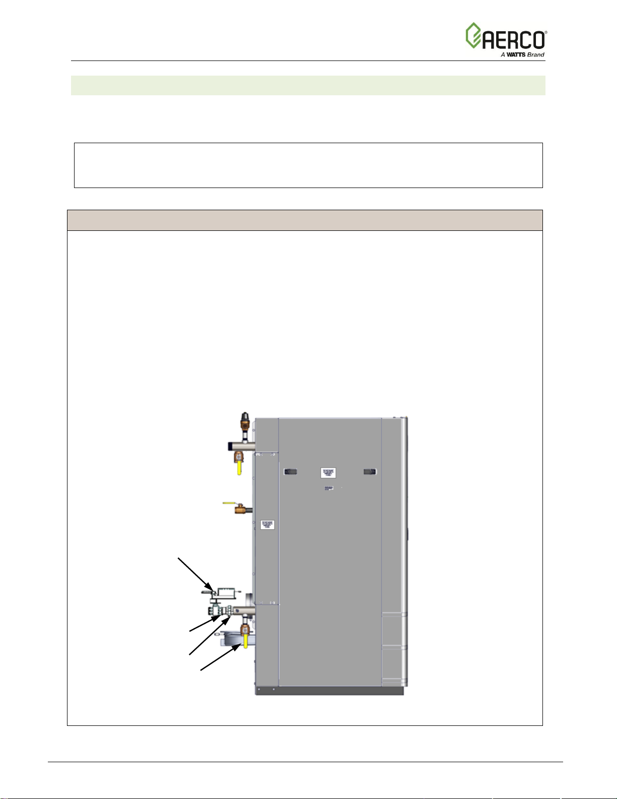
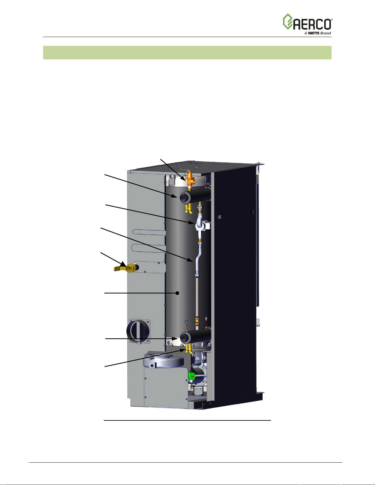
2.7 INTERNAL RECIRCULATION LOOP
The internal Recirculation Loop Assembly is located inside the unit enclosure at the rear of the
unit. In order to access this assembly, the right-rear panel must be removed, as shown in Figure
2.7.
This assembly contains a recirculation pump that connects the upper hot water outlet to the
lower cold-water inlet to the unit’s heat exchanger. The purpose of this loop is to provide feedforward (FFWD) temperature control by mixing a portion of the hot water outlet with the coldwater inlet to the unit. Temperature sensors located in the hot water outlet and cold-water inlet
provide temperature data to the Edge Controller. The Controller utilizes this data to modulate
the fire rate (Air/Fuel Valve position) to precisely maintain the hot water outlet temperature at
the selected setpoint temperature.
REAR VIEW – REAR PANEL & EXHAUST VENT REMOVED
Figure 2.7. Recirculation Loop
RECIRCULATION
LOOP PIPING
HOT WATER OUTLET
2” NPT
P&T VALVE
RECIRCULATION
PUMP
COLD WATER INLET
2” NPT
LOWER DRAIN VALVE
HEAT EXCHANGER
FUEL INLET
NATURAL GAS, 1.5” NPT
Innovation - Edge [i] Installation, Operation, Maintenance Manual
CHAPTER 2 – INSTALLATION
OMM-0143_A • GF-216 • 9/6/2019 Technical Support • (800) 526-0288 • Mon-Fri, 8 am - 5 pm EST Page 22 of 170
2.8 PRESSURE & TEMPERATURE RELIEF VALVE INSTALLATION
An ASME rated Pressure & Temperature (P&T) Relief Valve must be installed on each
Innovation water heater, on the hot water outlet at the top of the Recirculation Loop Assembly
as shown in Figure 2.7, above. The valve setpoint is 150 psig (1,034 kPa) at 210°F (98.9° C).
A suitable pipe joint compound should be used on the threaded connections. Any excess should
be wiped off to avoid getting any into the valve body. The relief valve should be piped to within 6
inches (15.2 cm) of the floor to prevent injury in the event of a discharge. The relief outlet piping
must be equal to the outlet size of the relief valve without reduction. No valves, restrictions, or
other blockages are allowed in the discharge line. In multiple unit installations the discharge
lines must not be manifolded together. Each must be individually run to a suitable discharge
location.
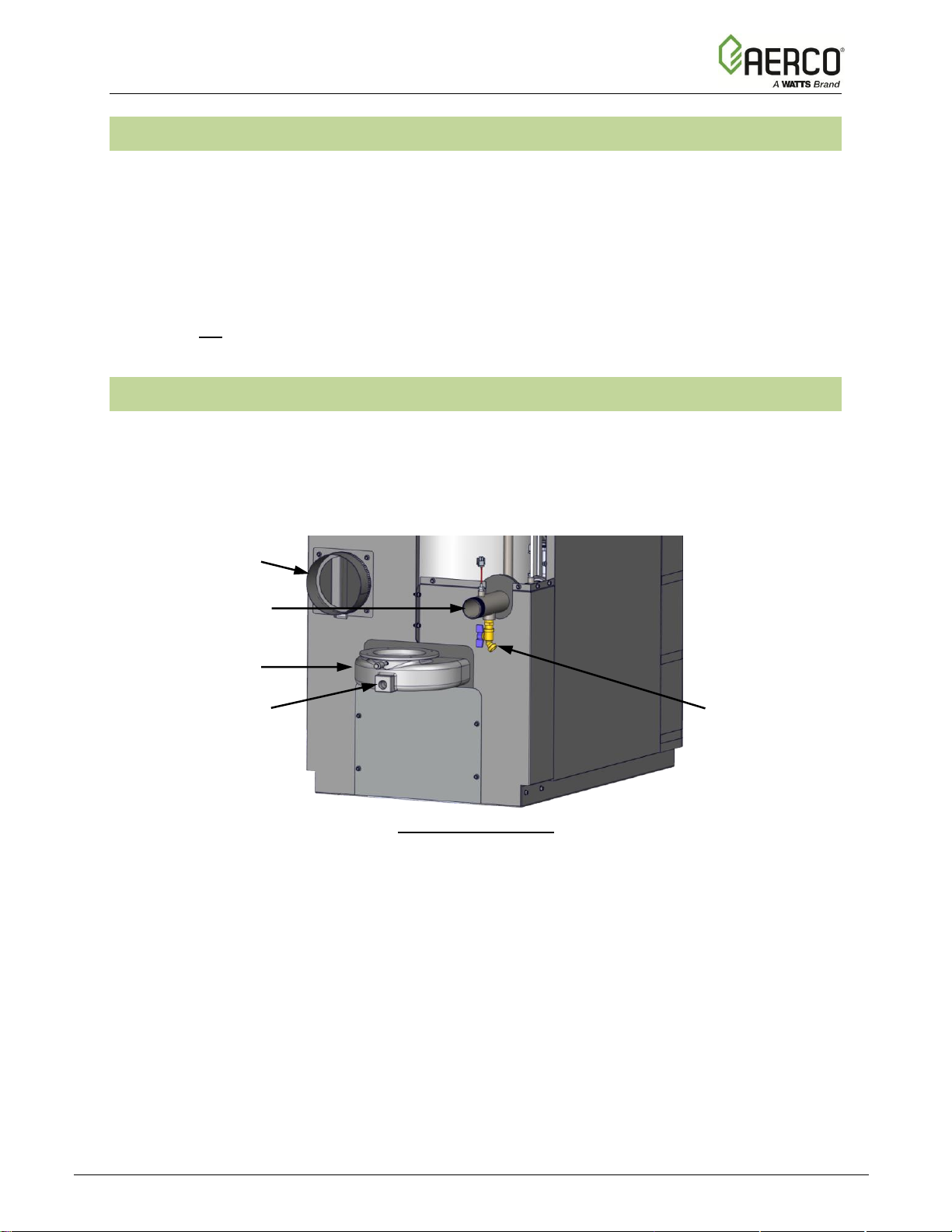
2.9 CONDENSATE DRAIN & PIPING
The Innovation Water Heater is designed to condense water vapor from the flue products.
Therefore, the installation must have provisions for suitable condensate drainage or collection.
The condensate drain port is located on the exhaust manifold at the rear of the unit (Figure 2.9-
1). This drain port must be connected to the Condensate Trap (P/N 99259), which is packed
within the unit’s shipping container.
PARTIAL REAR VIEW
Figure 2.9-1: Condensate Drain Connection Location
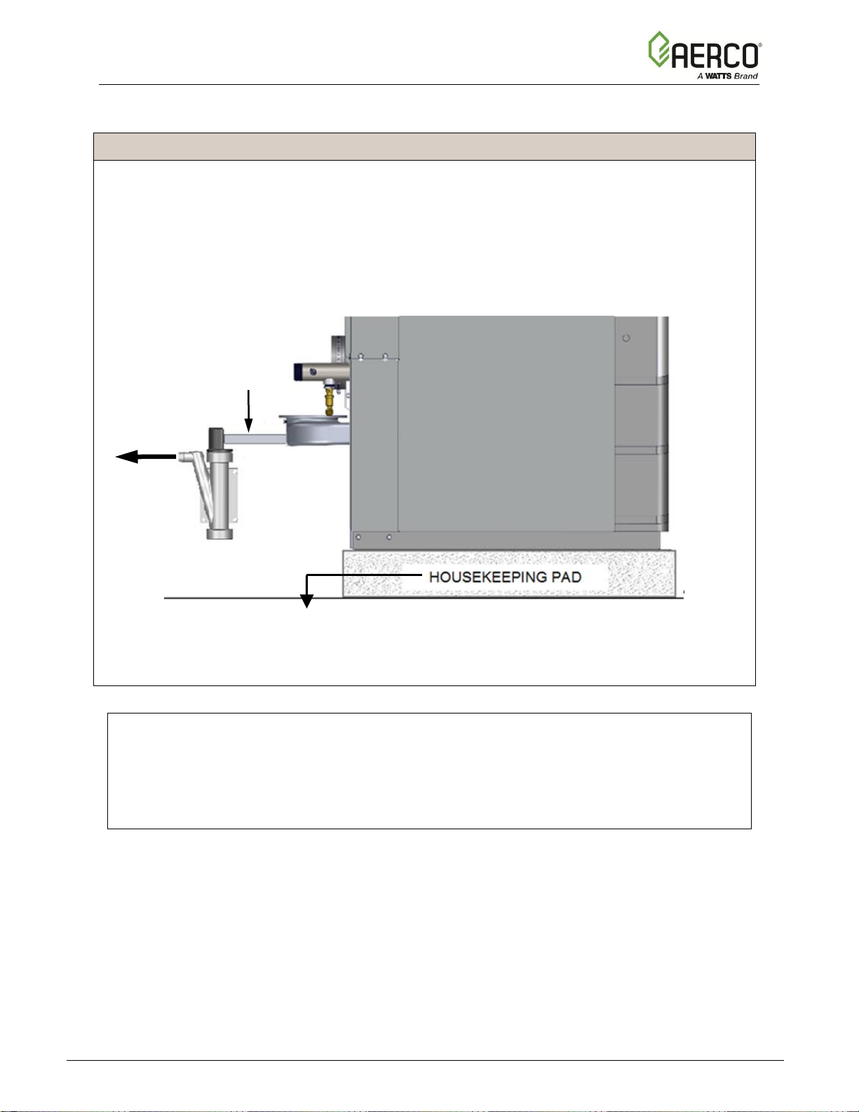
Sample Condensate Trap installation is shown in Figure 2.9-2. However, the actual installation
details for the trap will vary depending on the available clearances, housekeeping pad height/
dimensions and other prevailing conditions at the site. The following general guidelines must be
observed to ensure proper condensate drainage:
• The condensate trap inlet must be level with, or lower than the exhaust manifold drain
port.
• The base of the condensate trap can be supported to ensure that it’s level, but that’s not
required.
• The trap must be removable for routine maintenance (see Section 6.9 for instructions).
• If a floor drain is not available, a condensate pump can be used to remove the
condensate to a drain.
• The maximum condensate flow rate is 10 Gallons (37.85 L) per hour.
COLD WATER INLET
2” NPT
DRAIN VALVE
AIR INLET
EXHAUST MANIFOLD
CONDENSATE DRAIN
CONNECTION
3/4” NPT
Innovation - Edge [i] Installation, Operation, Maintenance Manual
CHAPTER 2 – INSTALLATION
OMM-0143_A • GF-216 • 9/6/2019 Technical Support • (800) 526-0288 • Mon-Fri, 8 am - 5 pm EST Page 23 of 170
While observing the guidelines above, install the condensate trap as follows:
CONDENSATE TRAP INSTALLATION Instructions
1. Attach the 3/4” NPT nipple (P/N 94136) to the exhaust manifold’s drain port.
2. Loosen the condensate trap’s cap, then install it on the open end of the 3/4“ nipple.
3. Rotate the cap so the outlet faces towards the condensate drain, then tighten it.
4. Connect a length of 3/4” (1.91 cm) I.D. hose to the trap outlet. Use PVC, stainless steel,
aluminum or polypropylene for condensate drain piping. DO NOT USE carbon or copper
components
5. Route the hose from the trap outlet to a nearby floor drain and secure it with a hose clamp.
Figure 2.9-2: Sample Condensate Trap Installation – Left Side View
NOTE:
As a general guideline, AERCO recommends use of its Condensate Neutralizer Kit to raise
the pH level of the condensate prior to drainage. At a minimum, the installation must be
designed in accordance with local codes that specify acceptable pH limits. For more
information, see Technical Instruction Document TID-0029, Condensate Neutralization Kit
and TID-0074 Condensate Neutralization Tank.
HOSE TO
FLOOR
DRAIN
Housekeeping pad should not extend
under the condensate assembly
3/4” NPT
NIPPLE
(P/N 94136)
Innovation - Edge [i] Installation, Operation, Maintenance Manual
CHAPTER 2 – INSTALLATION
OMM-0143_A • GF-216 • 9/6/2019 Technical Support • (800) 526-0288 • Mon-Fri, 8 am - 5 pm EST Page 24 of 170
2.10 GAS SUPPLY PIPING
The minimum, nominal and maximum allowable gas pressures are listed in the Innovation-Edge
Gas Supply Design Guide (TAG-0091, GF-5036). This guide must be consulted prior to
designing or installing any gas supply piping.
WARNING!
NEVER USE MATCHES, CANDLES, FLAMES OR OTHER SOURCES OF IGNITION TO
CHECK FOR GAS LEAKS.
CAUTION!
Many soaps used for gas pipe leak testing are corrosive to metals. Therefore, piping must be
rinsed thoroughly with clean water after leak checks have been completed.
NOTE:
All gas piping must be arranged so that it does not interfere with removal of any covers,
inhibit service/maintenance, or restrict access between the unit and walls, or another unit.
Innovation units contain a Natural Gas inlet connection on the rear of the unit. The location of
the gas inlet is shown in Figure 2.7, above.
Inlet Connection
Innovation Model
1.5 Inch (3.8 cm) Natural Gas
All INN models
Prior to installation, all pipes should be de-burred and internally cleared of any scale, metal
chips or other foreign particles. Do Not install any flexible connectors or unapproved gas
fittings. Piping must be supported from the floor, ceiling or walls only and must not be supported
by the unit.
A suitable piping compound, approved for use with natural gas, should be used. Any excess
must be wiped off to prevent clogging of components.
To avoid unit damage when pressure testing gas piping, isolate the unit from the gas supply
piping. The gas pressure applied to the unit should never exceed 14” W.C. (3.49 kPa).
Leak test all external piping thoroughly using a soap and water solution or suitable equivalent.
The gas piping used must meet all applicable codes.
2.10.1 Gas Supply Specifications.
The gas supply input specifications to the unit for Natural Gas is as follows:
• The maximum static pressure to the unit must not exceed 14” W.C. (3.49 kPa).
• The minimum pressure for Natural Gas is 4.0” W.C. (1.0 kPa).
• The gas supply pressure to the unit must be of sufficient capacity to provide the following
while maintaining a recommended (nominal) gas pressure of 7“ W.C. (1.74 kPa) with
the unit operating at maximum capacity:
o INN 600N: 625,000 BTU (183 kW)
o INN 800N: 800,000 BTU (234 kW)
o INN 1060N: 1,060,000 BTU (311 kW)
o INN 1350N: 1,350,000 BTU (410 kW)
Innovation - Edge [i] Installation, Operation, Maintenance Manual
CHAPTER 2 – INSTALLATION
OMM-0143_A • GF-216 • 9/6/2019 Technical Support • (800) 526-0288 • Mon-Fri, 8 am - 5 pm EST Page 25 of 170
2.10.2 Manual Gas Shutoff Valve
A manual shut-off valve is factory-installed in the gas supply line at the unit, as shown in Figure
2.5. Additionally, if a gas regulator is installed upstream of the unit, refer to Figure 2.10.3.2 to
determine the location of the manual shut-off valve installation in relation to the regulator. The
maximum allowable gas pressure to the Water Heater is 14” W.C. (3.49 kPa).
2.10.3 External Gas Supply Regulator
An external gas pressure regulator is required on the gas inlet piping under most conditions
(see Sections 2.10.3.1 and 2.10.3.2, below). Regulators must conform to the following
specifications:
• The external natural gas regulator must be capable of regulating 50,000 BTU/Hr. to
3,180,000 BTU/Hr. (58.61 kW to 932.0 kW) of natural gas while maintaining a gas
pressure of 8.0” W.C. (1.99 kPa) minimum to the unit.
• A lock-up style regulator is required when gas supply pressure exceeds 14” W.C. (3.49
kPa).
2.10.3.1 Massachusetts Installations Only
For Massachusetts installations, a mandatory external gas supply regulator must be
positioned as shown in Figure 2.10.3.2, below. The gas supply regulator must be properly
vented to outdoors. Consult the local gas utility for detailed requirements concerning venting
of the supply gas regulator.
2.10.3.2 All Installations (Except Massachusetts)
An external gas supply regulator is recommended for all installations (other than
Massachusetts) that exceed 7” W.C. (1.74 kPa) gas pressure, positioned as shown in
Figure 2.10.3.2. No regulator is required for gas pressures below 7” W.C. (1.74 kPa) of
pressure. Consult the local gas utility for detailed requirements concerning venting of the
supply gas regulator.
Figure 2.10.3.2: Manual Gas Shut-Off Valve Location
NOTE:
1.5” (3.8 cm)
MANUAL
SHUTOFF
VALVE
NATURAL GAS
SUPPLY
DIRT TRAP
GAS PRESSURE
REGULATOR

Innovation - Edge [i] Installation, Operation, Maintenance Manual
CHAPTER 2 – INSTALLATION
OMM-0143_A • GF-216 • 9/6/2019 Technical Support • (800) 526-0288 • Mon-Fri, 8 am - 5 pm EST Page 26 of 170
It is the responsibility of the customer to source and purchase the appropriate gas regulator
as described above. However, AERCO offers for sale an appropriate regulator, which may
be ordered at the time of unit purchase or separately. Contact AERCO for more information.
2.11 AC ELECTRICAL POWER WIRING
The AERCO Innovation-Edge Electrical Power Design Guide (TAG-0092, GF-5066) must be
consulted prior to connecting any AC power wiring to the unit. This guide includes electrical
power wiring diagrams.
External AC power connections are made to the unit inside the Power Box on the front of the
unit. Remove the front door of the unit to access the Power Box mounted directly above the
Edge Controller. Loosen the four Power Box cover screws and remove the cover to access the
AC terminal connections inside the Power Box.
POWER BOX LOCATION POWER BOX WITH COVER REMOVED
Figure 2.11-1: Power Box Location – Partial Front View, Front Panel Removed
The Power Box contains the terminal block shown in Figure 2.11-2. A wiring diagram showing
the required AC power connections is mounted on the front cover of the Power Box.
Figure 2.11-2: AC Terminal Block Configurations for 110 and 220 VAC Input
Units that connect to 220VAC power input must include a 220VAC to 120VAC transformer,
shown in Figure 2.11-3. Connect the incoming 220VAC electrical line to the same terminals in
the Power Box as the 120VAC line would be connected. The transformer is pre-wired to convert
the power to 120VAC. No further steps are needed
Innovation - Edge [i] Installation, Operation, Maintenance Manual
CHAPTER 2 – INSTALLATION
OMM-0143_A • GF-216 • 9/6/2019 Technical Support • (800) 526-0288 • Mon-Fri, 8 am - 5 pm EST Page 27 of 170
Figure 2.11-3: 220 VAC Transformer – Front and Side Panels Removed
2.11.1 Electrical Power Requirements
AERCO Innovation Heater built for the International market require the following input voltage:
• 120 VAC, single-phase, 50/60 Hz @ 20A
• 220 VAC, single-phase, 50/60 Hz @ 20A
NOTE:
All electrical conduit and hardware must be installed so that it does not interfere with the
removal of any unit covers, inhibit service/maintenance, or prevent access between the unit
and walls or another unit.
Each unit must be connected to a dedicated electrical circuit. NO OTHER DEVICES SHOULD
BE ON THE SAME ELECTRICAL CIRCUIT AS THE HEATER.
A double-pole switch must be installed on the electrical supply line in an easily accessible
location to quickly and safely disconnect electrical service. DO NOT attach the switch to sheet
metal enclosures of the unit.
After placing the unit in service, the ignition safety shutoff device must be tested. If an external
electrical power source is used, the installed water heater must be electrically bonded to ground
in accordance with the requirements of the authority having jurisdiction. In the absence of such
requirements, the installation shall conform to National Electrical Code (NEC), ANSI/NFPA 70
and/or the Canadian Electrical Code (CEC) Part I, CSA C22.1 Electrical Code.
220 VAC TRANSFORMER
Innovation - Edge [i] Installation, Operation, Maintenance Manual
CHAPTER 2 – INSTALLATION
OMM-0143_A • GF-216 • 9/6/2019 Technical Support • (800) 526-0288 • Mon-Fri, 8 am - 5 pm EST Page 28 of 170
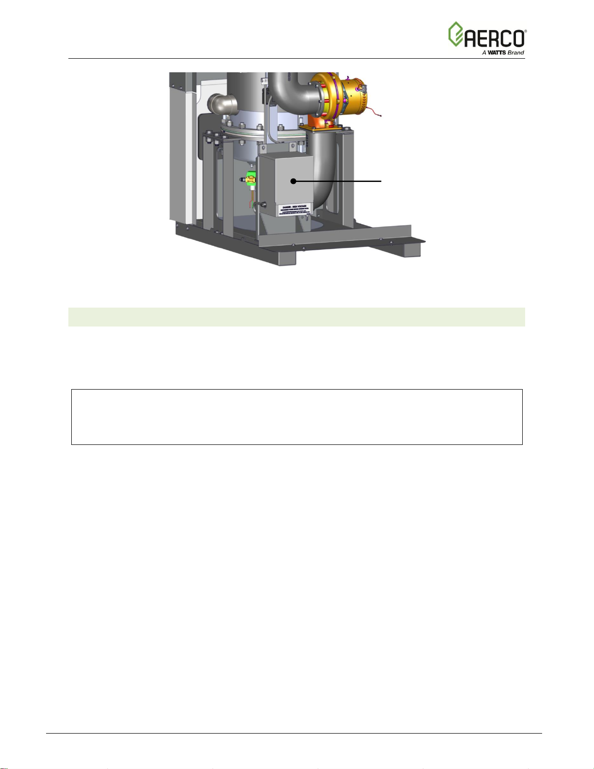
2.12 FIELD CONTROL WIRING
Each unit is fully wired from the factory with an internal operating control system. No field control
wiring is required for normal operation. However, the Edge Controller used with all Innovation
water heaters does allow for some control and monitoring features. Wiring connections for these
features are made in the Input/Output (I/O) Box. The I/O Box is located to the left of the
Controller’s front panel (Figure 2.12-1) behind the removable front panel door. To access the I/O
Box terminal strips shown in Figure 2.12-2, loosen the four cover screws and remove the cover.
All field wiring is installed from the rear of the panel by routing the wires through one of the four
bushings provided.
Figure 2.12-1: Input/Output (I/O) Box Location – Partial Front View
Refer to the wiring diagram provided on the cover of the I/O Box (Figure 2.12-2) when making
all wiring connections.
Since identical I/O Boxes are used with both AERCO gas-fired boilers and water heaters, some
of the input and output connections apply only to boilers while others are common to both
boilers and heaters. These I/O Box connections are noted in the sections below.
NOTE:
Use Figure 2.12-2 to determine the functions of the I/O PCB connections. Do not use the
silkscreened labels on the PCB itself, as these may not match.
CAUTION!
DO NOT make any connections to the I/O Box terminals labeled “NOT USED”. Attempting to
do so may cause equipment damage.

Innovation - Edge [i] Installation, Operation, Maintenance Manual
CHAPTER 2 – INSTALLATION
OMM-0143_A • GF-216 • 9/6/2019 Technical Support • (800) 526-0288 • Mon-Fri, 8 am - 5 pm EST Page 29 of 170
Outdoor Air
Air Sensor Common
Air Temp Sensor
O2 Sensor –
Not Used
Spark Signal +
Spark Signal –
O2 Sensor +
Not Used
+12 V Out
Analog In +
Analog In –
Valve Feedback +
Valve Feedback –
Shield
Shield
Analog Out +
Analog Out –
RS-485 +
RS-485 Ground
RS-485 -
RS-232 - TxD
RS-232 - RxD
VFD/Blower +
VFD/Blower –
Remote Intl’k OUT
Remote Intl’k IN
NOT USED
Delayed Intl’k OUT
Delayed Intl’k IN
Not Used
Fault Relay N.C.
Fault Relay COMM
Fault Relay N.O.
Aux Relay N.C.
Aux Relay COMM
Aux Relay N.O.
Not Used
Figure 2.12-2: I/O Box Terminal Strips – Shown with Wiznet Card
2.12.1 OUTDOOR AIR IN Terminal
The OUTDOOR AIR IN and AIR SENSOR COMMON terminals are not applicable to this unit.
2.12.2 COMBUSTION AIR Terminals
The COMBUSTION AIR and AIR SENSOR COMMON terminals are not applicable to this unit.
2.12.3 O2 SENSOR Terminals
The O2 SENSOR (–) and O2 SENSOR (+) terminals are not currently used in this unit.
2.12.4 SPARK SIGNAL Terminals
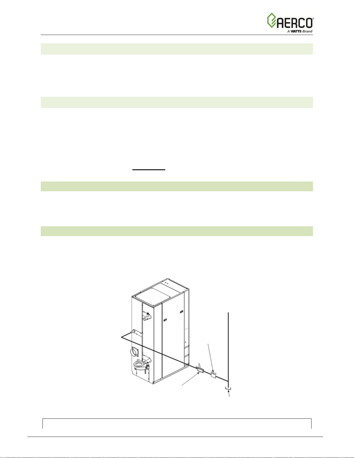
The SPARK SIGNAL terminals (+ & -) connect to the spark monitor (P/N 61034, also called "AC
Current transducer"), which monitors the current going to the ignition transformer (P/N 65085,
see Section 6.14). If the current is insufficient (too high or low) during the ignition sequence, the
controller will abort the ignition cycle. The controller will attempt up to three ignition cycles. If the
current is insufficient by the third try, the controller will shut down and display a fault message.
Relay Contacts:
120 VAC, 30 VDC
5 Amps, Resistive
DANGER!
120 VAC USED
IN THIS BOX
DIP 1 Modbus Term
DIP 2 RS232 Enable

Innovation - Edge [i] Installation, Operation, Maintenance Manual
CHAPTER 2 – INSTALLATION
OMM-0143_A • GF-216 • 9/6/2019 Technical Support • (800) 526-0288 • Mon-Fri, 8 am - 5 pm EST Page 30 of 170
2.12.5 ANALOG IN Terminals
The ANALOG IN terminals (+ & -) are used when an external signal is used to change the unit’s
setpoint or air/fuel valve position. There are four signal types:
• 4 to 20 mA
• 0 to 20 mA
• 1 to 5 VDC
• 0 to 5 VDC
The factory default setting is 4 to 20 mA, however this can be changed in the Remote Signal
parameter in Main Menu → Advanced Setup → Unit → Application Configuration (note,
Operating Mode must equal Remote Setpoint).
If voltage rather than current is selected as the drive signal, a DIP switch must be set on the
Interface Board, located inside the Edge Controller. Refer to Appendix G – Edge [i] Controller
Views for information on setting DIP switches. If Remote Signal is set to either 4 to 20 mA or 0
to 20 mA, DIP switch #4 in block SW1 must be set to mA. If Remote Signal is set to 1 to 5
VDC or 0 to 5 VDC, DIP switch #4 must be set to V.
All supplied signals must be floating (ungrounded) signals. Connections between the source
and the Heater’s I/O Box must be made using twisted shielded pair of 18–22 AWG wire such as
Belden 9841. Polarity must be maintained and the shield must be connected only at the source
end and must be left floating (not connected) at the unit’s I/O Box.
Whether using voltage or current for the drive signal, they are linearly mapped to a 40°F (4.44
°C) to 240°F (115.6 °C) setpoint or a 0% to 100% air/fuel valve position. No scaling for these
signals is provided.
2.12.6 VALVE FEEDBACK Terminals
The Valve Feedback terminals are used when the Sequencing Isolation Valve Feedback option
is selected. The Valve Feedback signal is connected to the “Valve Fdbk” terminals and is used
to confirm that the valve has properly opened or closed. If the Valve Feedback signal does not
match the Valve-Open or Valve-Close command for the time defined in the "Valve Fdbk timer"
entry, the controller will proceed as follows:
(a) If the valve fails with the Valve Stuck Open fault, the Valve Stuck Open message will be
displayed and the unit will remain active.
(b) If the valve fails with the Valve Stuck Closed fault, the Valve Stuck Closed message will
be displayed and the unit will shut down.
NOTE:
If the Valve Feedback option is used, Shorting Jumper #JP2 on the I/O Board will be inserted
at the factory.
2.12.7 SHIELD Terminals
The two SHIELD terminals are used to terminate any shields used on sensor wires connected to
the unit. Only shields must be connected to these terminals.
2.12.8 ANALOG OUT Terminals
The two ANALOG OUT terminals (+ & -) output from 0 to 20 mA and may be used to monitor
Setpoint, Outlet Temperature, Valve Position 4-20 mA, Valve Position 0-10v or be set to OFF.
Default setting in the Edge Controller is Valve Position 0-10 v and settings behave as follows:
1. 0-10VDC must be selected for the voltage output used by the controller to modulate the
combustion blower via the I/O Box terminals labeled VFD/BLOWER (Section 2.12.11).
 Loading...