

Page 1
AERCO International, Inc. • 100 Oritani Dr. • Blauvelt, New York 10913 • Phone: 800-526-0288
OMM-0063_0C
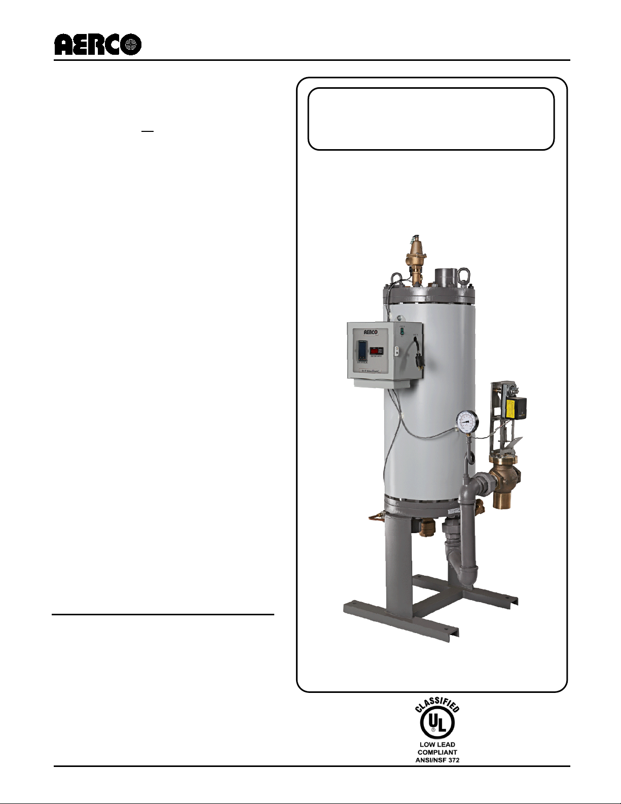
HE-110
USER MANUAL
Revised: 07/26/2013
Water Wizard
SW1B+II Packaged Water Heater with
Pneumatically Controlled Valve (CXT-P)
Installation, Operation, and Maintenance
Covers all 1B+ II models
Other applicable documentation includes:
including units with
pneumatically controlled valve
(Type CXT-P) or with an
Electronic Control System (ECS)
and electronically controlled
valve (CXT-E):
• B+03
• B+04
• B+05
• B+06
• B+07
• B+08
• B+09
• B+10
• B+11
• B+12
• B+13
• B+14
• B+15
Note: Number indicates number of
heating coils used (3 to 15).
Water Heaters
1B+ II
SB-2006-02: ECS Retrofit Instructions
AC-105: Electronic Controls System (ECS) Manual
AC-103: Pneumatic Temperature Controller Manual
Page 2

HE-110 1B+ II Water Wizard Water Heat er s
AERCO International, Inc. • 100 Oritani Dr. • Blauvelt, New York 10913 • Phone: 800-526-0288
Technical Support:
1-800-526-0288
www.aerco.com
OMM-0063_0C Installation, Operation & Maintenance Manual
(Mon–Fri, 8am-5pm EST)
Disclaimer
The information containe d in this manual is subject to c hange without notice from AERCO Inter national,
Inc. AERCO makes no warranty of any kind with respect to this material, including but not limited to
implied warranties of merchantability and fitness f or a particular application. AE RCO International is not
liable for errors appearing in this manual. Nor for incidental or consequential damages occurring in
connection with the furnishing, performance, or use of this material.
Page 2 of 50 MC2: 07/26/13
Page 3

1B+ I I Wa t er Wiza rd Water Heaters HE-110
AERCO International, Inc. • 100 Oritani Dr. • Blauvelt, New York 10913 • Phone: 800-526-0288
Installation, Operation & Maintenance Manual OMM-0063_0C
TABLE OF CONTEN TS
CHAPTER 1. SAFETY PRECAUTIONS ...................................................................................................... 5
CHAPTER 2. GENERAL INFORMATION.................................................................................................... 6
2.1. MODEL NAMES .......................................................................................................................... 6
2.2. HEAT EXCHANGER CONFIGURATIONS .................................................................................. 6
2.3. ACCESSORIES ........................................................................................................................... 6
2.4. ALL OTHER ITEMS ..................................................................................................................... 7
CHAPTER 3. INSTALLATION ................................................................................................................... 12
3.1. INSTALLING THE WATER WIZARD ......................................................................................... 12
CHAPTER 4. PRINCIPLE OF OPERATION .............................................................................................. 17
4.1. HEAT EXCHANGER OPERATION WITH PNEUMATIC CONTROL ......................................... 17
4.2. HEAT EXCHANGER OPERATION WITH ELECTRONIC CONTROL SYSTEM (ECS) ............ 18
CHAPTER 5. OPERATING PROCEDURES .............................................................................................. 19
CHAPTER 6. ROUTINE MAINTENANCE .................................................................................................. 22
6.1. DRAINING THE HEATER .......................................................................................................... 22
6.2. CHECKING THE DRAINED WATER ......................................................................................... 22
6.3. CHECKING THE TEMPERATURE CONTROL ......................................................................... 22
CHAPTER 7. TROUBLESHOOTING ......................................................................................................... 23
CHAPTER 8. CORRECITVE MAINTENANCE .......................................................................................... 24
CHAPTER 9. DE-SCALING BY THERMAL SHOCK METHOD ................................................................ 26
CHAPTER 10. MAINTENANCE DISASSEMBLY ...................................................................................... 27
10.1. TOOLS AND EQUIPMENT ........................................................................................................ 27
1.1.1. Common Tools and Equipment ............................................................................................. 27
1.1.2. Special Tools and Equipment Required: ............................................................................... 27
10.2. ISOLATING THE HEATER ........................................................................................................ 29
10.3. DISCONNECTING THE HEATER FROM THE FACILITY ......................................................... 30
10.4. ANTICIPATOR CHECK VALVE DISASSEMBLY ...................................................................... 31
11.5.1. Special Tools Required ..................................................................................................... 31
10.5. PREPARING TO REMOVE THE HEATER SHELL.................................................................... 32
10.6. REMOVING THE HEATER SHELL ........................................................................................... 33
10.7. REMOVING COILS AND RISERS ............................................................................................. 33
CHAPTER 11. CLEANING AND INSPECTION ......................................................................................... 34
11.1. PREPARATION OF BOTTOM HEAD ........................................................................................ 34
11.2. PREPARATION OF RISER AND RETURN ............................................................................... 34
11.3. PREPARATION OF COIL ASSEMBLIES .................................................................................. 35
11.4. PREPARATION OF COIL GASKETS ........................................................................................ 37
CHAPTER 12. MAINTENANCE REASSEMBLY ....................................................................................... 38
MC2: 07/26/13 Page 3 of 50
Page 4

HE-110 1B+ II Water Wizard Water Heat er s
AERCO International, Inc. • 100 Oritani Dr. • Blauvelt, New York 10913 • Phone: 800-526-0288
OMM-0063_0C Installation, Operation & Maintenance Manual
12.1. REASSEMBLY OF RISERS, SUB-COOLING COIL, AND STEAM COILS ............................... 38
12.2. SUB-COOLING COIL INSTALLATION ...................................................................................... 40
12.3. STEAM COIL INSTALLATION ................................................................................................... 40
12.4. HYDROSTATICALLY TESTING COILS & RISERS ............................................................................... 42
12.5. ANTICIPATOR CHECK VALVE REASSEMBLY .................................................................................... 42
12.6. REASSEMBLY OF SHELL ................................................................................................................ 43
12.7. REINSTALLING HEATER I N FACILITY ............................................................................................... 43
12.8. STARTUP PROCEDURE ................................................................................................................. 43
CHAPTER 13. RECOMMENDED SPARE PARTS .................................................................................... 44
Page 4 of 50 MC2: 07/26/13
Page 5
1B+ I I Wa t er Wiza rd Water Heaters HE-110
AERCO International, Inc. • 100 Oritani Dr. • Blauvelt, New York 10913 • Phone: 800-526-0288
! ! !
!
Installation, Operation & Maintenance Manual OMM-0063_0C
CHAPTER 1. SAFETY PRECAUTIONS
Installing or operat ing pers onnel m ust, at al l times , observe all safet y regulat ions. T he followin g warni ngs
are general and must be given the same attention as specific precautions included in the instructions.
WARNING
FLUIDS UNDER PRESSURE MAY CAUSE INJURY TO PERSONNEL OR
DAMAGE TO EQUIPMENT WHEN RELEASED.
SHUT OFF ALL INCOMING AND OUTGOING STEAM AND HOT WATER STOP VALVES AND
CAREFULLY DECREASE ALL TRAPPED TRESSURES TO ZERO (see SHUTDOWN IN
OPERATERING PROCEDURES) BEFORE PERFORMING ANY MAINTENANCE.
WARNING
LIVE STEAM CAN CAUSE SEVERE BURNS.
NEVER SEARCH FOR LEAKAGE IN A LIVE STEAM LINE BY SIGHT ALONE OR BY “FEEL.” USE A
MIRROR OR OTHER SUITIBLE POLISHED OBJECT. ALSO, ALWAYS WEAR GLOVES AND LONG
SLEEVES.
MC2: 07/26/13 Page 5 of 50
Page 6

HE-110 1B+ II Water Wizard Water Heat er s
AERCO International, Inc. • 100 Oritani Dr. • Blauvelt, New York 10913 • Phone: 800-526-0288
OMM-0063_0C Installation, Operation & Maintenance Manual
This instruction covers the AERCO Helitherm Model B+ WATER WIZARD Steam to Water
Heat Exchangers. STEAM is the PRIMARY or TUBE SIDE FLUID. The WATER BEING
HEATED is the Heat Exchanger (service or domestic water or other fluid) is the SECONDARY
or SHELL SIDE FLUID.
2.1. MODEL NAMES
The number of coils in a particular Heat Exchanger is denoted by the two digits following the
“B+” in the Heat Exchanger Model Number. That is: B+03 = 3 coils, B=07 = 7 coils, B+11 = 11
coils, and B+15 = 15 coils.
The Style designation for a Heat Exchanger denotes materials of construction for the various
components of the assembly. If this information is required for a specific Heat Exchanger,
contact the nearest AERCO Sales Representative.
2.2. HEAT EXCHANGER CONFIGURATIONS
There are three basic heat exchanger configurations; those with a pneumatically controlled
valve (CXT-P), those with Electronic Control System (ECS) with an electronically controlled
valve (CXT-E), and a “bare” heat exchanger without controls or valve. See separate ECS
Controls manual, AC-105, for information about the Electronic controls System and
electronically operated CXT-E valve. See Section 3 for available accessories.
2.3. ACCESSORIES
CHAPTER 2. GENERAL INFORMATION
Accessories included in the AERCO B+ Heater Package Assembly (See Figures 1a, 1b, 1c,
21, 22, and 23) include:
• Steam Flow Control Valve – either Air-Operated or Self-Contained as ordered and
furnished, sized as required for the service.
• Temperature Controller – installed in the Control Box when an Air Operat ed Control Valve is
furnished (See Fig. 20, Item 134).
• Over-Temperature Limit System, including the following:
• Temperature Switch – installed in the Control Box (Figure 20, Item 126).
• Solenoid Valves:
o Water – installed in the Heater Top Head.
o Air – installed in the Control Box when an Air Operated Control Valve is furnished
(Fig. 20, Item 135).
o Steam – installed on the Self-Contained Control Valve when such valve is furnished.
o Indicator Lights: “Power On” and “Tripped” – installed in the Control Box (Figure 20,
Items 129 and 130).
• Steam Compound Pressure Gage – mounted below the Control Box (Figure 20, Item 133).
• Shell Hot Water Outlet Temperature Gage – mounted below the Control Box (Figure 20,
Item 1 32).
• Pressure & Temperature Relief Valves – size and number furnished as required in
accordance with the design BTU output of the heater – first two located in the heater Top
Page 6 of 50 MC2: 07/26/13
Page 7

1B+ I I Wa t er Wiza rd Water Heaters HE-110
AERCO International, Inc. • 100 Oritani Dr. • Blauvelt, New York 10913 • Phone: 800-526-0288
Installation, Operation & Maintenance Manual OMM-0063_0C
Head as shown in Figure 1a, 1b, 1c, and 1d. The third, if furnished, to be installed in the hot
water outlet piping by the user as shown in Figure 2.
• Union Orifice – located in the Condensate Outlet (Figure 12, Item 55) – required in place of
a steam trap to ensure complete condensation of the steam within the heater.
• Check Valve – located in the Condensate Outlet (Figure 12, Item 53).
2.4. ALL OTHER ITEMS
Stop valves, check valves, strainers, unions or flanges, and other piping and f ittings as s hown in
Figures 3 through 6 – are to be furnished by USER.
NOTE:
This instruction covers only the heat exchanger portion of the model B+
packaged heater assembly. Separate instructions are included in this package
covering steam control valve, the over-temperature limit system and its
components, and other accessories included in the heater package.
NOTE:
The AERCO Helitherm heat exchanger carries the standard AERCO warranty
against defective material and workmanship. However, AERCO cannot honor its
warranty if the installer or user deviates in any way from the instructions and
precautions included herein and/or make any alteration of the equipment from
that furnished without the written approval of AERCO.
MC2: 07/26/13 Page 7 of 50
Page 8
HE-110 1B+ II Water Wizard Water Heat er s
AERCO International, Inc. • 100 Oritani Dr. • Blauvelt, New York 10913 • Phone: 800-526-0288
Chapter 2
OMM-0063_0C Installation, Operation & Maintenance Manual
General Information
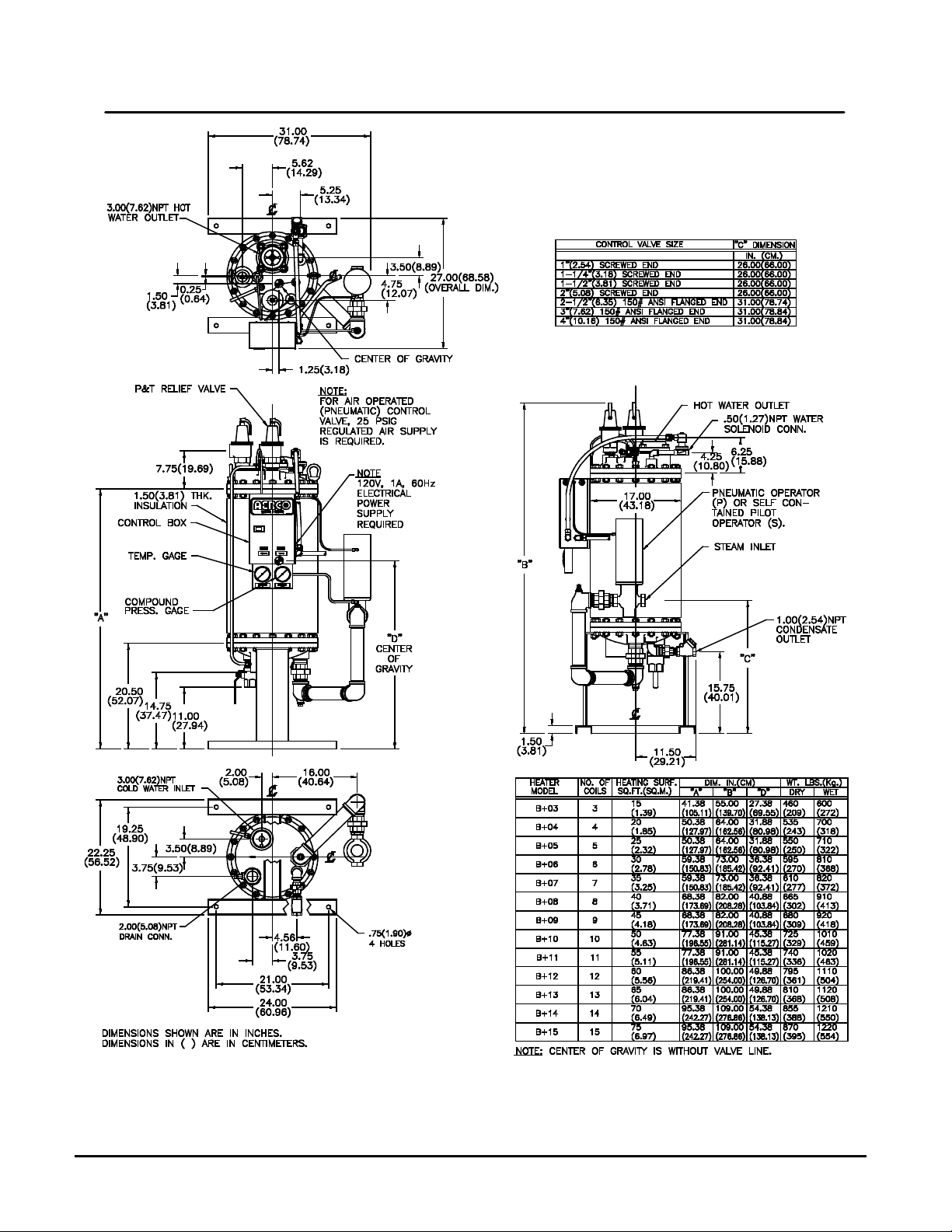
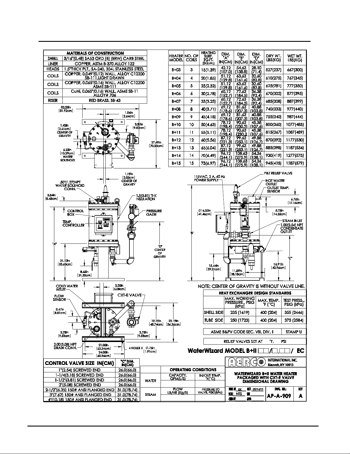
Figure 1a – Dimensions for AERCO Helitherm Heat Exchanger (Packaged Water Heater),
Model Water Wizard SW1B+II with Pneumatic CXT-P Valve
Page 8 of 50 MC2: 07/26/13
Page 9
1B+ I I Wa t er Wiza rd Water Heaters HE-110
AERCO International, Inc. • 100 Oritani Dr. • Blauvelt, New York 10913 • Phone: 800-526-0288
Installation, Operation & Maintenance Manual OMM-0063_0C
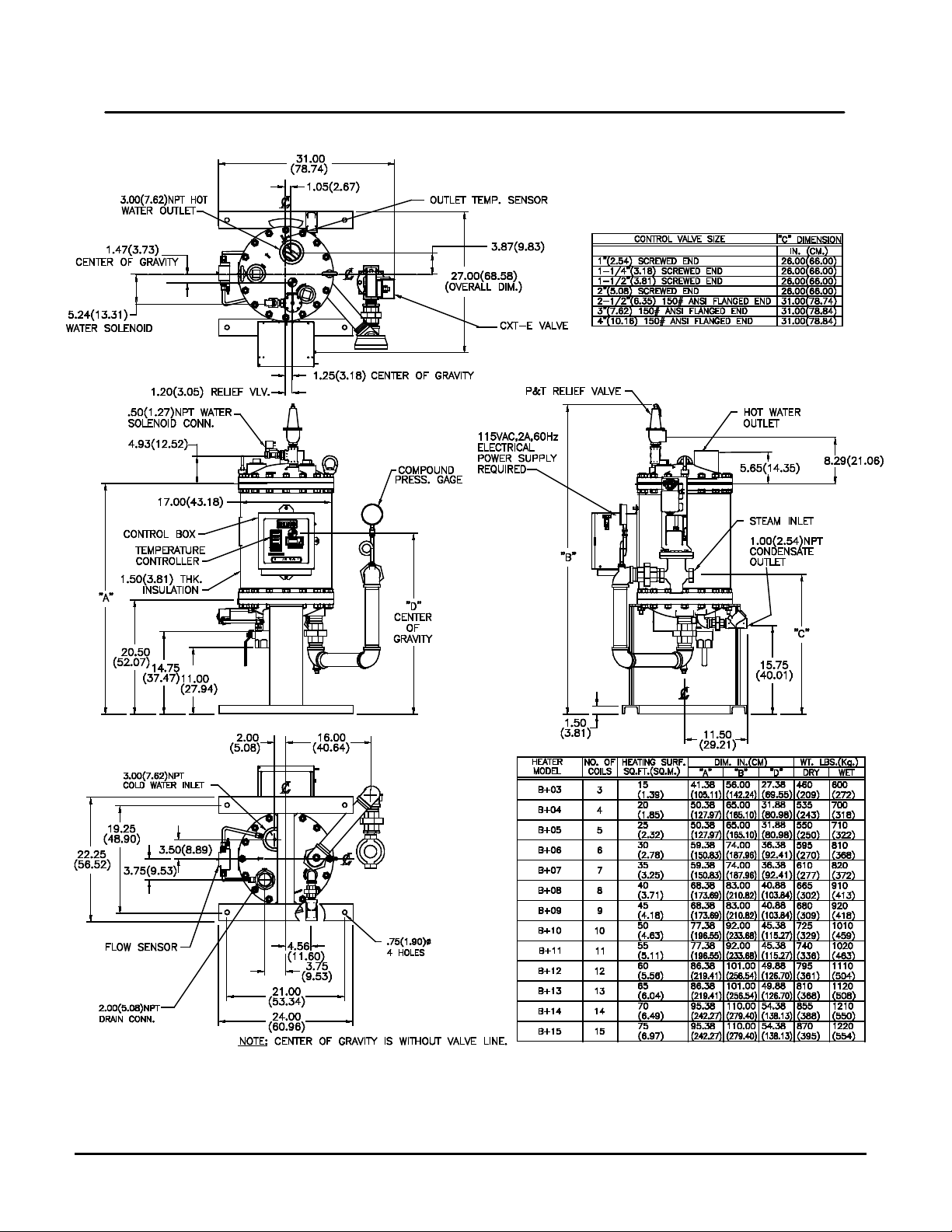
Figure 1b – Dimensions for AERCO Helitherm Heat Exchanger (Packaged Water Heater),
Model Water Wizard SW1B+II with Bronze Heads, ECS, and CTX-E Valve
MC2: 07/26/13 Page 9 of 50
Page 10
HE-110 1B+ II Water Wizard Water Heat er s
AERCO International, Inc. • 100 Oritani Dr. • Blauvelt, New York 10913 • Phone: 800-526-0288
OMM-0063_0C Installation, Operation & Maintenance Manual
Figure 1c – Dimensions for AERCO Helitherm Heat Exchanger (Packaged Water Heater),
Model Water Wizard SW1B+II with Stainless Steel Heads, ECS, and CTX-E Valve
Page 10 of 50 MC2: 07/26/13
Page 11
1B+ I I Wa t er Wiza rd Water Heaters HE-110
AERCO International, Inc. • 100 Oritani Dr. • Blauvelt, New York 10913 • Phone: 800-526-0288
Chapter 3
Installation, Operation & Maintenance Manual OMM-0063_0C
Installation
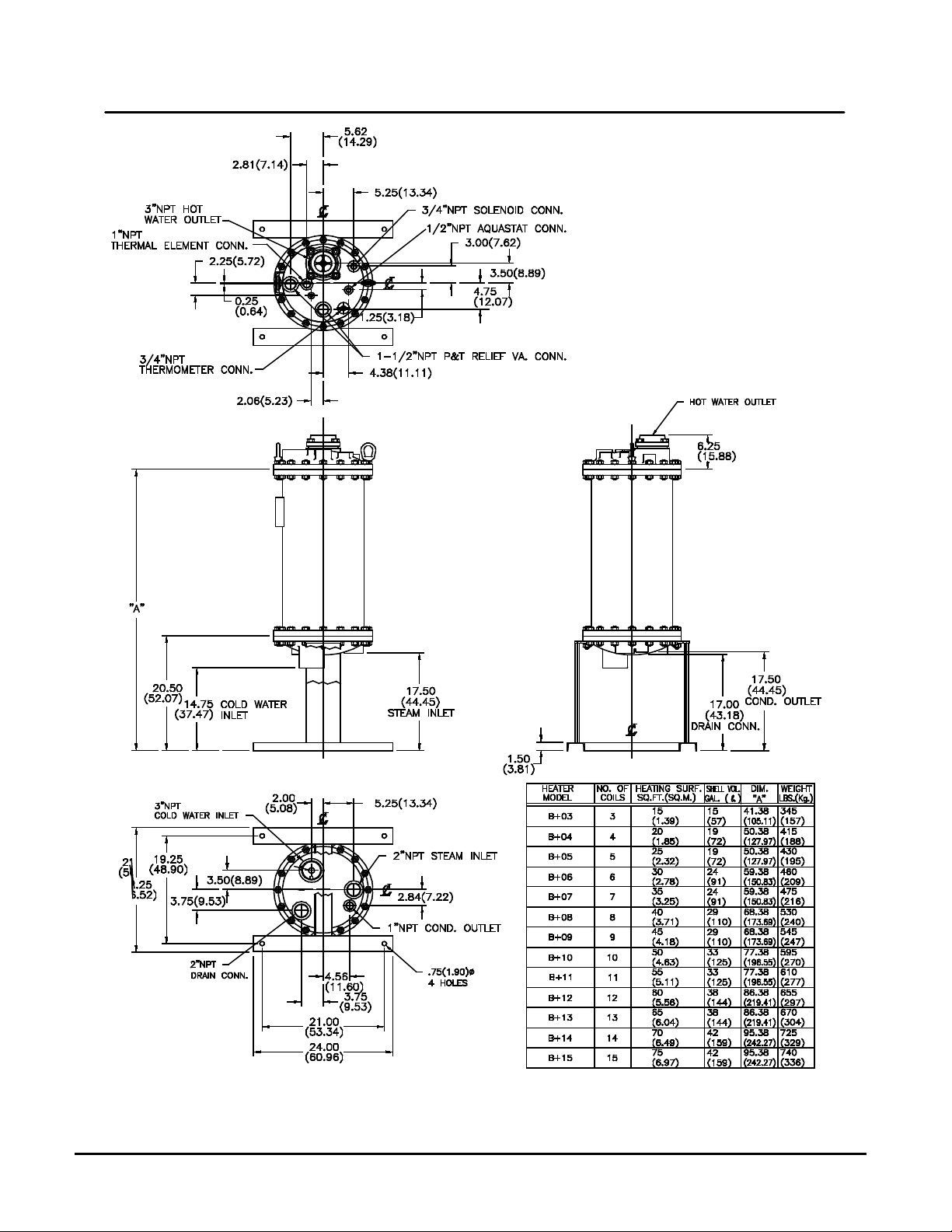
Figure 1d – Dimensions for AERCO Bare Helitherm Replacement Heat Exchanger for
Model Water Wizard SW1B+II
MC2: 07/26/13 Page 11 of 50
Page 12
HE-110 1B+ II Water Wizard Water Heat er s
AERCO International, Inc. • 100 Oritani Dr. • Blauvelt, New York 10913 • Phone: 800-526-0288
OMM-0063_0C Installation, Operation & Maintenance Manual
CHAPTER 3. INSTALLATION
3.1. INSTALLING THE WATER WIZARD
To install the Water Wizard SW1B+II water Heater, follow the steps below:
Installing the Water Wizar d H eat er Instructions
1) Dimensions for three versions of AERCO Model SW1B+II are shown in Figures 1a, 1b, and
1c.
2) Uncrate the Heater carefully. Set the Heater upright by using a block and tackle or hoist
attached to the lifting lug on the top of the Heater (the eye-bolt s s hown in Fig ur e 15). Always
use the lifting lugs to lift and/or move the Heater.
3) If possible, for easy in-place maintenance, locate the Heater where there is at least 2 feet
clearance all around the Heater and where the head room clearance from the top of
dimension B in Figure 1 is at least equal to dimension A for the Heater Model, less 24
inches.
4) It is suggested that the Heater stand assembly be secured to the floor, however, any other
means for securing the Heater may be used. If piping is used to secure the Heater, the
piping must include ample provision for expansion.
5) Make all piping connections as instructed in Step 6 below and per the appropriate Figures
shown:
a) Single Heater – Figure 3
b) Parallel Heaters – Figure 4
c) Single Heater used with an Accumulator – Figure 5
d) Single Heater used with a Stratified Storage Tank – Figure 6
or with any specific piping diagram which may have been furnished by AERCO for this
installation.
6) For the best Heater performance, OBSERVE THE FOLLOWING VERY CAREFULLY in
making the piping installation:
a) Do not use cement or red lead in making up pipe joints
b) For Heater connection types, sizes, and exact locations, see Figure 1.
c) All piping to the Heater top head should be provide with unions or flanges which are
LOCATED BEYOND THE OUTSIDE DIAMETER OF THE HEATER HEAD to permit
removal of the head and shell for in-place maintenance.
d) Include all of the stop valves, check valves, steam traps, and other elements in the
piping as shown in Figure 3, 4, 5, or 6, or as separately specified by AERCO. Note
that the check valve shown at the Heater in the Condensate return line is furnished in
the piping package assembly by AERCO.
e) The Condensate return piping MUST be arranged to permit Condensate to drain
freely by gravity from the Heater Bottom Head. Failure to do so may result in
improper Heater operation and/or in damage to the Heater Steam/Condensate
system.
(Continued)
Page 12 of 50 MC2: 07/26/13
Page 13
1B+ I I Wa t er Wiza rd Water Heaters HE-110
AERCO International, Inc. • 100 Oritani Dr. • Blauvelt, New York 10913 • Phone: 800-526-0288
Installation, Operation & Maintenance Manual OMM-0063_0C
Installing the Water Wizar d H eat er I nst ructions (Cont.)
f) All drain discharges – relief valve(s) in the Top Head of the Heater, outlet of the
Water Solenoid Valve in the top head of the Heater, and Drain Valve in the Bottom
Head of the Heater – should be piped directly to a convenient floor drain.
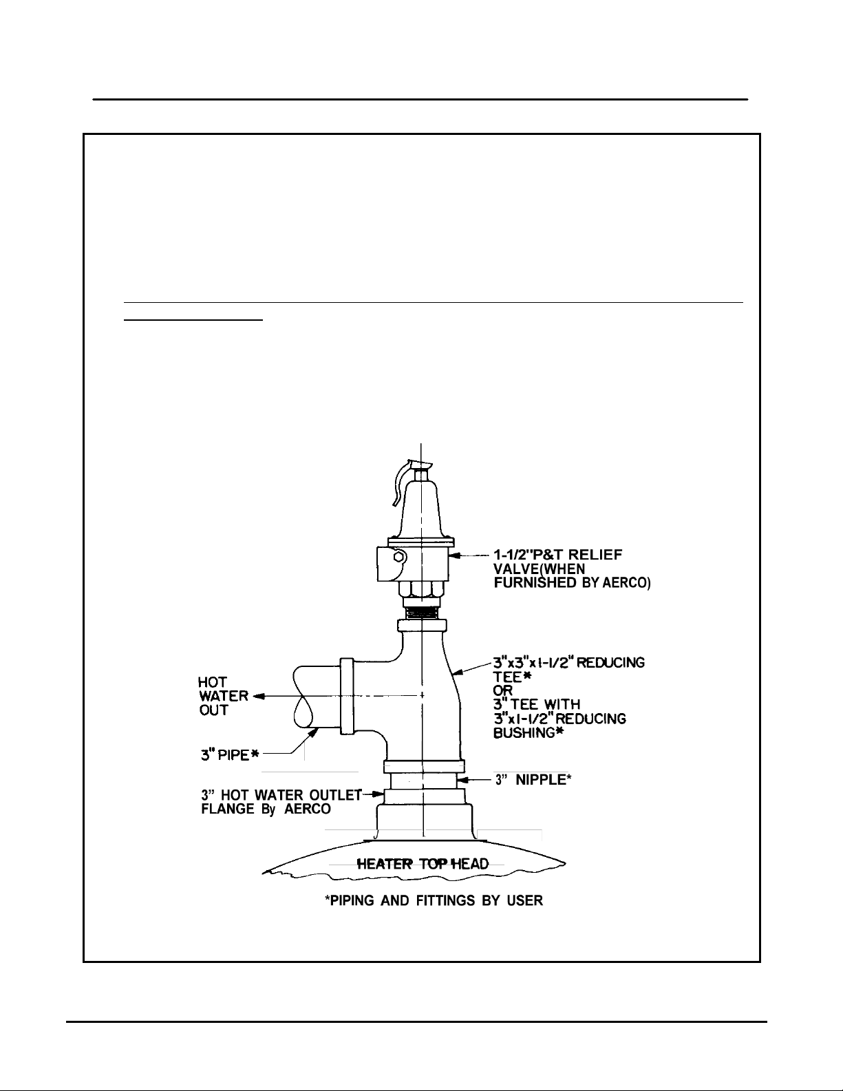
7) When a third P&T Relief Valve is furnished with the Heater (the first two furnished have
been assembled in the top head of the Heater by AERCO), the t hird Valve is to be installed
in the Heater hot water outlet piping, by the user, as illustrated in Figure 2.
8) Before making final piping connections to and from the Heater and Cont rol Valve, blow out
all piping thoroughly.
9) If an air-operated Control Valve is furnished in the Heater package, make the necessary
supply air connection to the connector through the side of the Control Box (see Figure 20,
Item 136). The supply air pressure must be maintained at 20 PSIG.
10) Connect 110 volt 60 Hz power supply wiring through the side of the Control Box to the
electrical Junction Box (see Figure 20, Item 127).
Figure 2 – P&T Relief Valve Located in the Heater Hot Water Outlet Piping
MC2: 07/26/13 Page 13 of 50
Page 14
HE-110 1B+ II Water Wizard Water Heat er s
AERCO International, Inc. • 100 Oritani Dr. • Blauvelt, New York 10913 • Phone: 800-526-0288
OMM-0063_0C Installation, Operation & Maintenance Manual
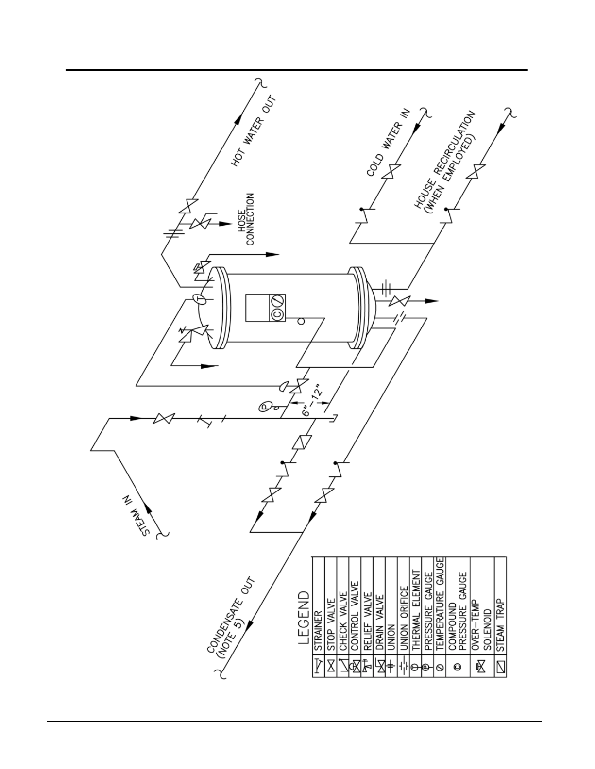
Figure 3 – Piping Connections for a Single Heater
Page 14 of 50 MC2: 07/26/13
Page 15

1B+ I I Wa t er Wiza rd Water Heaters HE-110
AERCO International, Inc. • 100 Oritani Dr. • Blauvelt, New York 10913 • Phone: 800-526-0288
Installation, Operation & Maintenance Manual OMM-0063_0C
MC2: 07/26/13 Page 15 of 50
Page 16

HE-110 1B+ II Water Wizard Water Heat er s
AERCO International, Inc. • 100 Oritani Dr. • Blauvelt, New York 10913 • Phone: 800-526-0288
Chapter 4
OMM-0063_0C Installation, Operation & Maintenance Manual
Figure 4 – Piping Connections for Parallel Heaters
Figure 5 – Piping Connections for a Single Heater used with an Accumulator
Principal of Operation
Figure 6 – Piping Connections for a Single Heater used with a Stratified Storage Tank
Page 16 of 50 MC2: 07/26/13
Page 17

HE-110 1B+ II Water Wizard Water Heat er s
AERCO International, Inc. • 100 Oritani Dr. • Blauvelt, New York 10913 • Phone: 800-526-0288
OMM-0063_0B Installation, Operation & Maintenance Manual
CHAPTER 4. PRINCIPLE OF OPERATION
The AERCO Helitherm Heat Exchanger (Heater) consists of three parts (see Figure 7);
1. Shell with Top and Bottom Heads
2. Coils assembled to Steam Riser and Condensate Return
3. Integral Demand Anticipator Temperature Control Unit
Cold Water (or other liquid) enters the heater through the inlet connection and Orifice in the
Bottom Head and strikes the Deflector. The Orifice serves to divert some Cold Water into the
Shut Tube, whereas the Deflector disperses the incoming Cold Water evenly into the bottom of
the Shell. The Cold Water in the Shell, then, flow upward among the Coils (heating surfaces)
and, heated, is discharged through the Check Valve and Hot Water Outlet Connection in the
Top Head.
Steam enters through the Control Valve and the Steam inlet connection in t he Heater Bottom
and is fed through the Steam Riser to the inlet of each Heat Exchanger Coil unit as shown in
Figure 7. The Steam flows through these Coils units simultaneously in parallel and enters the
Condensate Return as Condensate. The Condensate is fed through the Sub-Cooling Coil unit
and leaves the Heater through the Condensate outlet connection in the Bottom Head of the
Heater. The Sub-Cooling Coil unit is included in the assembly to provide the maximum possible
condensing of the Steam, thus providing the greatest amount of heat transfer, the lowest
Condensate outlet temperature, and the greatest reduction in energy loss from flash steam.
As noted above, the Cold Water being heated flows through the Heater from bottom to top. In
addition, Heater Water, being of less density than Cold Water, migrates to the top of the Shell
by convection. These actions result in the hottest Water always being at the top of the Heater –
at the Heater outlet and at the How Water inlet to the Anticipator Temperature Sensing Tube –
See Figure 7.
Hot Water from the top of the Heater Shell enters the open end of the Sensing Tube and Cold
Water enters the Sensing Tube from the Shunt Tube at a r ate proportional to the load (call for
Hot Water) on the Heater. The mixture of Hot and Cold W ater in the Sensing Tube creates an
average temperature which necessarily will be cooler than t he temperature of the Hot Water in
the top of the Heater Shell.
4.1. HEAT EXCHANGER OPERATION WITH PNEUMATIC CONTROL
The Temperature Sensing Element “reads” the average temperature of the Water in the
Sensing Tube at any given moment and signals the Water in the Sensing Tube at any given
moment and signals the Steam Control Valve to modulate between full open or closed as
necessary to maintain the req uired Heater Hot Water outlet temperature. With no demand or
load on the Heater, the Temperature Sensing Element reads only the temperature of the W ater
in the top of the Heater and at the Heater outlet. If that Water is at the required outlet
temperature or above, the Sensing Element signals the Steam Control Valve to close.
However, the moment that there is a demand for Hot Water, Cold Water flows from the Shunt
Tube to mix with the Hot Water I the Sensing Tube, cooling the Sensing Element so that is
signals the Steam Control Valve to open. The need for Steam (heat) to the Coils is satisfied at
once, the incoming Cold Water passing over the Coils is heated, and the Hot Water outlet
temperature does not fall below that required.
The Demand Anticipator Temperature Control Unit, as its name implies, is constantly alert to
lead conditions and changes, as well as to changes in the temperature of the incoming Cold
Page 18

HE-110 1B+ II Water Wizard Water Heat er s
AERCO International, Inc. • 100 Oritani Dr. • Blauvelt, New York 10913 • Phone: 800-526-0288
OMM-0063_0C Installation, Operation & Maintenance Manual
Water, and provides FEED-FORWARD temperature control at all times.
Figure 7 – Schematic of AERCO Model B+II Water Heater showing Anticipator
Temperature Control
4.2. HEAT EXCHANGER OPERATION WITH ELECTRO NIC CONTROL SYSTEM
(ECS)
The Electronic Control System (ECS) available for the Water Wizard SW1B+II offers
features and functions not described in this manual. Refer to the separate manual, AC105, for detailed descriptions of the function and operation of the ECS and electr onically
operated valve, type CXT-E.
Page 18 of 50 MC2: 07/26/13
Page 19

1B+ I I Wa t er Wiza rd Water Heaters HE-110
AERCO International, Inc. • 100 Oritani Dr. • Blauvelt, New York 10913 • Phone: 800-526-0288
Installation, Operation & Maintenance Manual OMM-0063_0C
CHAPTER 5. OPERATING PROCEDURES
Water Wizard Operating Procedure Instructions
1) W ith the installation entirely completed, including:
1) All piping connections have been made,
2) All connecting piping has been cleaned (blown) out,
3) All connections per Steps 8 and 9 under INSTALLATION have been made,
Open the stop valve in the Cold Water inlet line and hold the relief valve (or any one of the
relief valves) in the Heater top head open to allow air to come out (otherwise an air pocket
will be built up and the Heater will not fill). When water flows out of the relief valve, the
Heater is full.
2) Temporarily set the Over-Temperature Limit System Temperature Switch in the Control Box
(Figure 20, Item 126) to its high temperature limit.
3) If the Steam Control Valve furnished is air operated and there is a Temperature Controller in
the Control Box (see Figure 8), set the Controller at t he temperature desired to be held at
the Heater Hot Water outlet.
4) Open the stop valve in the Hot Water outlet line. Open a Hot Water faucet or faucets in the
building or process to insure a flow of water thr ough t he heater. For best results in adjusting
the temperature control, a water flow of 10% to 25% of heater rating is desirable. Slowly
open all stop valves in the Steam inlet and condensate outlet lines.
5) Slowly open all stop valves in the Steam inlet and Condensate outlet lines.
6) Follow the instructions furnished with the air -operated Temperature Controller and Control
Valve or with self-contained Temperature Regulator Valve, and:
a) Introduce Steam to the Heater.
b) Adjust the air-operated Temperature Controller OR self-contained Temperature
Regulator Valve until the Heater hot water outlet temperature is being held steady at
the desired temperature. If the hot water outlet temperature is erratic, see Step 7
below.
c) Close the hot water faucet or faucets opened in Step 4.
7) Open any stop valves in the building recirculation system if such is included in the Heater
installation.
8) If the hot water outlet temperature is erratic especially during load changes:
a) Put a load on the Heater, by opening a hot water faucet or faucets in the building or
process, as quickly as possible.
b) Adjust the Temperature Controller of Temperature Regulator to provide best
response on load changes. See the instruction furnished with the Controller or
Regulator.
9) Adjust the Over-Temperature Limit System Temperature Switch in the Control Box to its
proper setting in accordance with the instructions furnished which cover the OverTemperature Limit System – usually 15°F to 20°F higher than the desired hot water outlet
temperature.
(Continued)
MC2: 07/26/13 Page 19 of 50
Page 20

HE-110 1B+ II Water Wizard Water Heat er s
AERCO International, Inc. • 100 Oritani Dr. • Blauvelt, New York 10913 • Phone: 800-526-0288
OMM-0063_0C Installation, Operation & Maintenance Manual
Water Wizard Operating Procedure Instructions (Cont.)
10) The Heater installation is now set for operation. No further operation procedure is
necessary unless or until further temperature control adjustments may be required. If so,
repeat Steps 4, 5, 6, 7, and, if necessary, Step 8.
11) To SHUT DOWN the System:
a) Close all stop valves in the Steam inlet and Condensate outlet lines.
b) In this order, close the stop valves in
i. the hot water outlet line,
ii. the recirculation line, if any, and
iii. t he c old water inlet line (see Step 11c, which follows).
c) If the system includes an accumulator or stratified storage tank, DO NOT SHUT O FF
THE COLD WATER UNTIL T HE HEATER HAS COOLED DOWN. If the system is
allowed to cool while the cold water is shut off, the Heater liner may collapse
because of formation a vacuum in the Heater.
12) For DRAINING THE HEATER, see the instruction included under ROUTINE
MAINTENANCE, Chapter 6, Section 6.1.
13) To START UP again, with the shell filled per Step 1 above, open the stop valves in the
following order:
1) stop valve in the Cold Water inlet line,
2) any stop valve in the recirculation line, if any,
3) stop valve in the Hot Water outlet line, and
4) stop valves in the Steam inlet line and Condensate outlet lines.
14) After each startup, check the temperature control. If necessary, make adjustments per
Steps 4 through 9.
Page 20 of 50 MC2: 07/26/13
Page 21

1B+ I I Wa t er Wiza rd Water Heaters HE-110
AERCO International, Inc. • 100 Oritani Dr. • Blauvelt, New York 10913 • Phone: 800-526-0288
Installation, Operation & Maintenance Manual OMM-0063_0C
Figure 8 – Model B+II Heater Control Box
Figure 9 – Over-Temperature Limit System Wiring Diagram
MC2: 07/26/13 Page 21 of 50
Page 22

HE-110 1B+ II Water Wizard Water Heat er s
AERCO International, Inc. • 100 Oritani Dr. • Blauvelt, New York 10913 • Phone: 800-526-0288
OMM-0063_0C Installation, Operation & Maintenance Manual
CHAPTER 6. ROUTINE MAINTENANCE
6.1. DRAINING THE HEATER
The constant flexure of the Heater coils under varying load conditions automatically provides a
de-scaling action and prevents a buildup of brittle scale. A periodic blowdown (draining) is
required to remove accumulated solids.
After the first 3 months of initial operation, drain the Heater as follows:
(1) Close all stop valves in the Steam inlet and Condensate outlet lines.
(2) In this order, close the stop valves in
a) the hot water outlet line,
b) the recirculation line, if any, and
c) the cold water inlet line.
(3) Carefully open the relief valve (or one of the relief valves) in the Heater top head to relieve
pressure in the Heater shell. If water continues to flow fr om the relief valve one of the stop
valves either leaks or is not shut off t ight. This must be rem edied until there is no mor e f low
through the relief valve.
(4) With the relief valve being held open, (to prevent creating a vacuum in the shell) open the
drain valve and drain the Heater completely.
(5) To refill the Heater and place it back into operation, close the drain valve and proceed
through Steps 1, 12, and 13 under OPERATING PROCEDURES, Chapter 5.
6.2. CHECKING THE DRAINED W ATER
The constant flexure of the Heater coils under varying load conditions automatically provides a
de-scaling action and prevents a buildup of brittle scale. A periodic blowdown (draining) is
required to remove accumulated solids.
After the first 3 months of initial operation, drain the Heater as outlined below. Examine the
water being drained.
(a) If the amount of solids appears to be heavy, set a schedule to drain the Heater every 3
months.
(b) If the amount of solids appears to be light, set a schedule to drain the Heater every 6
months.
(c) Even if the amount of solids appears to be very light, set a schedule to drain the Heater
at least once each year.
(d) Also see TROUBLESHOOTING, Chapter 7 and CORRECTIVE MAINTENANCE,
Chapter 8. If de-scaling by thermal shock is required, schedule that procedure in your
ROUTINE MAINTENANCE, Chapter 9.
6.3. CHECKING THE TEMPERATURE CONTROL
Check the t emperature control at least once every 3 months. Make any necessary adjustments
per Steps 4 through 8 under OPERATING PROCEDURES, Chapter 5.
Page 22 of 50 MC2: 07/26/13
Page 23

1B+ I I Wa t er Wiza rd Water Heaters HE-110
AERCO International, Inc. • 100 Oritani Dr. • Blauvelt, New York 10913 • Phone: 800-526-0288
PROBABLE CAUSE & REMEDY
Installation, Operation & Maintenance Manual OMM-0063_0C
CHAPTER 7. TROUBLESHOOTING
SYMPTOM
Heater does not maintain required temperature at rated
capacity.
Heater overheats.
Hot Water outlet temperature fluctuates widely.
Insufficient Water through or from Heater.
Excess or insufficient Condensate being returned from
Heater.
Steam being discharged into Condensate drain,
Pressure/Temperature Relief Valve pops.
Heater shuts down below, at, or too near above required
Hot Water temperature.
Loud banging in heater or in Steam or Condensate piping
(not to be confused with normal clicking noise).
“CORRECTIVE MAINTENANCE” ITEM NO.
1, 2, 6, 12, 14, 17, 18, 19
1, 5, 6, 8, 11, 13, 14
2, 6, 11-14, 17, 19
3, 15
6, 7
18, 19
4-6, 8-11, 13, 14, 16
16
6, 7, 9, 10
MC2: 07/26/13 Page 23 of 50
Page 24

HE-110 1B+ II Water Wizard Water Heat er s
AERCO International, Inc. • 100 Oritani Dr. • Blauvelt, New York 10913 • Phone: 800-526-0288
OMM-0063_0C Installation, Operation & Maintenance Manual
CHAPTER 8. CORRECITVE MAINTENANCE
Refer to table in TROUBLESHOOTING, Chapter 7 for a description of problematic symptoms.
The following are probable causes and remedies for improper function of the Heater.
1. The temperature gage or steam pressure gage, or the Steam supply pressure gage
ahead of the Control Valve, may be wrong. Check each with a gage which is known to
be correct.
2. Steam pressure is too low. Check the steam supply pressure gage ahead of the
Control Valve. If the reading is low, adjust the steam supply pressure to that which is
required. If there is a restriction in the steam supply line, the gage reading will drop
excessively when the Heater calls for full steam even though the pressure appears to be
normal when the load is light. If the steam supply pressure is correct, the steam gage
(below the Control Box) reading should reach design pressure for steam in the coils as the
Heater temperature drops. If it does not, check the operation of the Control Valve.
3. Cold Water pressure is low. Check and correct, if necessary, the Water pressure to the
Heater.
4. Static pressure of the Cold Water is too high. Make the necessary corrections to bring
the Water pressure below that for which the Relief Valve(s) is set.
5. Water to be heated is preheated too hot. Reduce the preheating to a temperature at least
10°F under the desired Heater hot water outlet temperature.
6. Condensate return piping has not been installed so that the Condensate drains freely
by gravity and/or the Condensate check valve leaks or has failed. If necessary,
rearrange the Condensate return piping per Step 6e under INSTALLATIION, Chapter 3.
Inspect the check valve and replace it if it is leaking or has failed. Also, check to make sure
there is no restriction in the Condensate drain line.
7. Steam supply line is not properly trapped. Install trap as indicated in Figure 2, 3, 4, or 5.
8. Leaking stop valve in bypass line, if any, around the Steam Control Valve. Maintain
the stop valve to shut tight.
9. Lack of expansion tank in the hot water system. Install an expansion tank in the outlet
hot water line close to the heater.
10. I nsufficient shock absorbers. Insert shock absorbers (water hammer arresters) in both
the cold and hot water systems as needed to eliminate shock waves.
11. The Steam Control Valve does not close. Check the instructions covering the Valve.
12. The Steam Control Valve does not open. Check the instructions covering the Valve.
13. The temperature control thermal element (connected to the air-operated
Temperature Controller or the self-contained Control Valve and located in the Heater
top head) has failed. Refer to the instructions covering the Temperature Controller or
Control Valve.
14. The Anticipator Unit system is not operating properly. Check to make sure that the
temperature sensing element has not failed (see Item 13, above), that the shunt tube ( item
Page 24 of 50 MC2: 07/26/13
Page 25

1B+ I I Wa t er Wiza rd Water Heaters HE-110
AERCO International, Inc. • 100 Oritani Dr. • Blauvelt, New York 10913 • Phone: 800-526-0288
Installation, Operation & Maintenance Manual OMM-0063_0C
87 in Figures 17 and 18) has not become clogged, and that the check valve at the hot
eater outlet is working properly (see Item 15, below). Make any necessary corrections.
15. The Anticipator Check Valves at the Heater hot water outlet is not worki ng properly.
Disassemble and inspect the Check Valve, clean the Valve, and repair or replace any parts
as necessary per Steps 1 through 5 under DISASSEMBLY, Chapter 10, Section 10.4.1.
16. The Over-Temperat ure Limit System is out of adjustment of some component of the
system has failed. Check out the systems setting per Step 8 under OPERATING
PROCEDURES, Chapter 5. Inspect and repair or replace each component as necessary.
17. There is a l eak i n t he Heater coil(s), steam riser, or condensate return, causing water
from the shell to leak into the heating coil system, or steam or condensate from the
coil system to the shell. To verify such a leak, shut off the steam supply and break a
connection in the Condensate Line – CAREFULLY to avoid being burned. Condensate will
drain from the coil system initially, but the flow should stop after a minute or two. If the flow
continues, water is leaking from the pressurized shell side to the tube side of the Heater.
Disassemble, inspect, repair (if possible), replace, and reassemble the Heater as outlined
below under DISASSEMBLY, Chapter 10, and REASSEMBLY, Chapter 12.
18. The Heater coils are scaled up. De-scale the Heater by thermal shock in the manner
outlined below under DESCALING BY THERMAL SHOCK METHOD, Chapter 9.
19. The Heater is being utilized at a rate higher than its design capacity. Contact the
nearest AERCO Representative for advice in remedying this problem.
MC2: 07/26/13 Page 25 of 50
Page 26

HE-110 1B+ II Water Wizard Water Heat er s
AERCO International, Inc. • 100 Oritani Dr. • Blauvelt, New York 10913 • Phone: 800-526-0288
De-Scaling by Thermal Shock Instructions
consult the nearest AERCO Representative for advice.
OMM-0063_0C Installation, Operation & Maintenance Manual
CHAPTER 9. DE-SCALING BY THERM AL SHOCK ME THO D
Where, under certain conditions of continuous steady usage, the Cold Water is so hard or
alkaline that normal flexure of the Heater coils (see Routine Maintenance) and routine blow
down (draining the Heater shell) will not remove scale buildup on the coils, the heating surfaces
(coils) may be thermally shocked, without damage to any part of the Heater, to dislodge scale
solids.
1) Drain the Heater per steps 1 through 4, Chapter 6, ROUTINE MAINTENANCE, Chapter 6.
However, instead of holding the relief valve open in step 4, remove the relief valve, shown as
Item 73(A) in Figure 17 or 18 from the Heater top head.
2) Open the Heater drain valve. Leave the drain valve open until step 8 below.
3) Connect a source of cold water (for example, a hose from a cold water faucet) to the open
relief valve connection.
4) Open all shutoff valves in the Steam inlet line and the Condensate outlet line to allow Steam
to the Heater. After about 30 seconds, or until Steam is blowing out of the Condensate drain
line, close the stop valve in the Condensate outlet line. Leave the Steam inlet line open for
about two minutes longer, and then close all Steam inlet stop valves.
5) Inject a flow of cold wate r t hrough the relief valve connection for about two minutes. Then shut
off the cold water flow and open the Condensate line stop valve to drain off all Condensate.
6) Repeat steps 4 and 5 several times until the water coming from the Heater drain appears to
be relatively free of solids.
7) Remove the cold water source from the relief valve connection. Open the stop valve in the
main Cold Water inlet line and allow a complete flushing of the Heater shell.
8) After the Heater shell has been completely drained, close the Heater drain valve, and place
the Heater back into operation per steps 1, 12, and 13 under OPERATING PROCEDURES,
Chapter 5.
9) If Cold W ater conditions are so severe that thermal shocking does not remove scale deposits,
Page 26 of 50 MC2: 07/26/13
Page 27

1B+ I I Wa t er Wiza rd Water Heaters HE-110
AERCO International, Inc. • 100 Oritani Dr. • Blauvelt, New York 10913 • Phone: 800-526-0288
Installation, Operation & Maintenance Manual OMM-0063_0C
CHAPTER 10. M AINTEN ANCE DI SASSEMBLY
10.1. TOOLS AND EQUIPMENT
The following common and special tools and equipment are required to perform the instructions
contained in this chapter:
10.1.1. Common Tools and Equipment
• Combination Wrenches: 7/16”, 5/8”, 13/16”, 1-1/16”, 1-1/8”
• Pipe Wrenches: 12” and 24”
• Chain Hoist
• Voltmeter:
• Brass Wire Brush
• Needle-Nose Pliers
• Gasket Removal Tool
• Carpenter’s Square
• Teflon Tape
• Orange Citric Cleaner
• Black Marker
10.1.2. SPECIAL TOOLS AND EQUIPMENT REQUIRED:
• Hydrostatic Pressure Pump: Range= Up to 235 psig
• Torque Wrench, 75 ft.-lbs. With 1-1/4” , 1-5/16” & 1-1/2” Open-End Spanners
(1-1/4” Open-End Spanner required for “A” Heater Only)
• Coil Retaining Tool (Figure 1)
• Coil Spacing Tool (Figure 1)
• Short-Length Wrenches: 1-1 /4” , 1-5/16”, 1-1/2”
(Overall wrench lengths should be approx. 6 inches or less)
MC2: 07/26/13 Page 27 of 50
Page 28

HE-110 1B+ II Water Wizard Water Heat er s
AERCO International, Inc. • 100 Oritani Dr. • Blauvelt, New York 10913 • Phone: 800-526-0288
OMM-0063_0C Installation, Operation & Maintenance Manual
Figure 10: Tool Fabrication Details: Coil Spacing and Retaining Tools
Recommended Material: 1018 steel
Page 28 of 50 MC2: 07/26/13
Page 29

1B+ I I Wa t er Wiza rd Water Heaters HE-110
AERCO International, Inc. • 100 Oritani Dr. • Blauvelt, New York 10913 • Phone: 800-526-0288
Isolating the Heater Instructions
Installation, Operation & Maintenance Manual OMM-0063_0C
NOTE:
The procedures in the following paragraphs are arranged to isolate, disconnect
and disassemble the unit to the extent necessary to repair or replace defective
items. These procedures should be performed in the order specified to minimize
repair time.
10.2. ISOLATING THE HEATER
To isolate the Heater from all facility energy sources (steam, water, electrical, etc.), proceed as
follows:
1) Disconnect and Lock-Out/Tag-Out external AC power supplied to the Control Box and any
other devices connected to the Heater.
2) Using a voltmeter, check to ensure that all incoming voltage readings are zero Before
continuing.
3) If the Heat er is equipped with a Pneumatic Steam Valve, close the valve supplying air inlet
pressure to the Pneumatic Controller.
4) Close all stop valves in the Steam Inlet and Condensate Outlet lines
5) On the water-side, close the stop valves in the following order:
6) Carefully open the Relief Valve located on the T op Head to relieve pressure in the Heater
7) W hile holding the Relief Valve open to prevent creating a vacuum in the Shell, open the
• Hot water outlet line
• Recirculation line
• Cold water inlet line
Shell. Water should stop flowing from the valve within one minute. If water continues to
flow from the Relief Valve, one of the water stop valves is not securely closed.
Drain Valve in the Bottom Head on the Heater. Completely drain the potable water from the
Heater.
MC2: 07/26/13 Page 29 of 50
Page 30

HE-110 1B+ II Water Wizard Water Heat er s
AERCO International, Inc. • 100 Oritani Dr. • Blauvelt, New York 10913 • Phone: 800-526-0288
Disconnecting the Heater from the Facility Instructions
OMM-0063_0C Installation, Operation & Maintenance Manual
10.3. DISCONNECTING THE HEATER FROM THE FACILITY
To disconnect the Heater from the facility piping and wiring connections, proceed as follows:
1) First, check the ceiling height to determine if the Heater Shell and Top Head can be hoisted
up with the Heater remaining in position.
2) If there is sufficient ceiling clearance to permit safe elevation of the Shell assembly, skip to
step 8. If there is insufficient clearance, proceed to step 3 to remove the Heater from its
current location.
3) Using a 5/8” c ombination wrench, remove the Steam Pressure Line from the Steam Line and
Pressu re Gaug e.
4) Disconnect the Steam line from the Valve and Bottom Head.
5) Disconnect the water inlet from the Bottom Head.
6) Disconnect the drain line from the Bottom Head.
7) Disconnect the Condensate Drain piping from the Bottom Head.
8) Disconnect all electrical wires to the Control Box. Also, disconnect all wiring between the
Control Box and any external Solenoid Valve(s).
9) Using a 5/8” combination wrench, remove the Steam Pressure line from the Steam Line and
Pressure Gauge, if it was not performed in step 3.
10) Remove the water outlet piping from the Top Head.
11) Remove the pipe drain(s) from the Pressure Relief Valve(s).
12) Disconnect the pipe drain from the Water Solenoid Relief Valve.
13) Using a 13/16” combination wrench, disconnect the compression fittings on the Cold Water
Feed Tube from the Top Head and Bottom Head.
14) If controlled by a Pneumatic Valve, disconnect the incoming air supply to the Control Box and
Steam Valve.
15) If controlled by a Self-contained Valve, remove the thermal well from the Top Head that is
attached to the Valve.
Page 30 of 50 MC2: 07/26/13
Page 31

1B+ I I Wa t er Wiza rd Water Heaters HE-110
AERCO International, Inc. • 100 Oritani Dr. • Blauvelt, New York 10913 • Phone: 800-526-0288
Anticipator Check Valve Disassembly Instructions
Installation, Operation & Maintenance Manual OMM-0063_0C
10.4. ANTICIPATOR CHECK VALVE DISASSEMBLY
To disassemble the Anticipator Check Valve, proceed as follows:
10.4.1. Special Tools Required
• Torque wrench for 5/8” nuts.
• A block and tackle or ratchet hoist is recommended for lifting off the Heater top head and
shell, or for lifting and moving the Heater.
1) Shut down the Heater in accordance with Step 10 under OPERATING PROCEDURES.
2) Disconnect the union in the Hot water outlet piping (the one located beyond the outside
3) Separ at ely, lift the Spring Plate Assembly (33), the Gasket (32), the Spring (34), the Washer
4) Clean all parts and gasket surfaces thoroughly, and repair or replace any part necessary to
Manually (and carefully) open a relief valve to relieve any pressure in the Heater shell.
Figure 11 – Model B+II Heater Control Box
diameter of the Heater top head). Then remove the Nuts (51) and the Outlet Flange (31) and
outlet piping.
(35), and the Valve Plug (35).
make the Check Valve operate properly (open on water flow through the Heater).
MC2: 07/26/13 Page 31 of 50
Page 32

HE-110 1B+ II Water Wizard Water Heat er s
AERCO International, Inc. • 100 Oritani Dr. • Blauvelt, New York 10913 • Phone: 800-526-0288
Preparation for Heater Shell Removal Instructions
OMM-0063_0C Installation, Operation & Maintenance Manual
10.5. PREPARING TO REMOVE THE HEATER SHELL
Note that all part item numbers are given in parentheses ( ) in the instructions below refer to
those shown in Figures 14, 15, 16, 17, or 18.
Also, Note that it is not necessary to disassemble or remove the Check valve Assembly (see
above) in order to remove the Heater Shell.
1. Shut down and drain the Heater in accordance with Steps 1 through 4 in ROUTINE
MAINTENANCE, Chapter 6.
2. If a self-contained Control Valve is being used, remove the Valve’s Temperature Control
Thermal Element from the Thermal Well Bushing (62) in the Heater Top Head. Be careful not
to damage the Element or its capillary.
3. Disconnect ALL external piping from the Heater Top Head, including that to the Relief Valve(s)
(67) and the Water Solenoid Valve (73). Disconnect the Hot Water outlet piping at the union or
flange located beyond the outside diameter of the Heater Top Head.
4. Disconnect the power supply wiring to the Control Box and all wiring between the Control Box
and any outside Solenoid Valve(s).
5. Disconnect the Pressure Gage pressure line Compression Fitting (60).
6. Disconnect the Compression Fitting (59), located at the bottom of the Shunt Tubing (69) from
the Heater Bottom Head.
Figure 12: Part Reference for Heater Shell Removal
Page 32 of 50 MC2: 07/26/13
Page 33

1B+ I I Wa t er Wiza rd Water Heaters HE-110
AERCO International, Inc. • 100 Oritani Dr. • Blauvelt, New York 10913 • Phone: 800-526-0288
Heater Shell Removal Instructions
Removal of Coils and Risers Instructions
Installation, Operation & Maintenance Manual OMM-0063_0C
10.6. REMOVING THE HEATER SHELL
Remove the Heater Shell as follows:
1) Using a black marker, mark the edge of the Heater Bott om Head flange and Shell flange in ord er to
indicate their correc t relative positions upon reas semble. The Top Head can r emain attached to the
Shell.
2) Using the 1-1/16” c ombination wr ench, unbolt the sixteen stu ds and nuts around the bottom r ing of the
Shell. The two nuts loca ted in-line with the m ounting skid legs are to be removed with the s tud left in
place.
3) Attach a chain h oist to the two lifting lu gs on the Top Head. Lif t the Shell up to clear t he internal coil
bundle.
4) Using a light source, visually inspect the inside of the Heater Shell for evidence of damage to the
Copper Shell Liner. If any area of the Copper Liner is dam aged, replace t he Shell down on t he Bottom
Head and contact your local AERCO Representative to process return of the Heater to AERCO for
repair.
5) Move the heat exchanger bundle a few feet to the side so that the Shell can be lowered to t he floor.
Set the Shell on clean surface. Use care to avoid damaging the bottom edge of the Copper Shell Liner.
10.7. REMOVING COILS AND RISERS
The Coil Assemblies, Riser and Condensate Return are removed as follows:
1) Using the proper size open-end wrench, loosen the two Union Nuts securing the Coils to the
2) Using a pipe wrench, remove the Steam Riser and Condensate Return from the Bottom Head.
Steam Riser and Condensate Return.
MC2: 07/26/13 Page 33 of 50
Page 34

HE-110 1B+ II Water Wizard Water Heat er s
AERCO International, Inc. • 100 Oritani Dr. • Blauvelt, New York 10913 • Phone: 800-526-0288
Preparation of Bottom Head Instructions
Preparation of Riser and Return Instructions
Visually inspect all Steam Riser and Condensate Return Spuds, (Figure 2) threads and
!
!
OMM-0063_0C Installation, Operation & Maintenance Manual
CHAPTER 11. CLE ANING AND INSPECTION
Prior to reassembling Heater components, the Bottom Head, Steam Riser, Condensate Return
and Coils must be cleaned, inspected and prepared as described in the following paragraphs:
10.8. PREPARATION OF BOTTOM HEAD
The Bottom Head of the Heater must be cleaned, inspected and prepared for reassembly
as follows:
1) Clean off all debris from the topside of the Bottom Head.
2) Visually inspect the internal pipe threads where the Risers ar e connected. The overall depth
3) If the threads are less than the required depth, use the appropriate 1” or 2” NPT tap to clean
4) Using the g asket removal tool, remove the Shell Gasket from the Bottom Head. Use care t o
5) Apply pipe dope to the internal NPT threads in the Bottom Head.
of threads should measure, (1-1/8” for 2” NPT and 1” for 1” NPT)
out the threads.
avoid creating scratches or indents in the Bottom Head casting’s gasket surface area. Any
linear scratches can potentially create a leak.
10.9. PREPARATION OF RISER AND RETURN
The Riser and Return piping of the Heater must be cleaned, inspected and prepared for
reassembly as follows:
1)
2) Using a brass wire brus h, clean the threads of the Spuds. Use care to avoid scrat ching the
3) Using a brass wire brush, clean the pipe threads on the Riser. After cleaning, wipe with a
4) W rap two layers of Teflon tape around the Riser NPT threads.
sealing surfaces for damage, scratches, braze material and cleaning deposits. If defects are
found with the Spud threads or sealing surfaces, contact your AERCO Representative for
instruction to return the defective Riser.
sealing surfaces of the Spuds. Scratches can cause a leak pat h under the Coil Gasket. After
brush cleaning, wipe with a clean lint-free cloth.
clean lint-free cloth.
CAUTION
The use of Teflon tape or any lubricant on the threads of the spuds is
prohibited and may void the warranty.
Page 34 of 50 MC2: 07/26/13
Page 35

1B+ I I Wa t er Wiza rd Water Heaters HE-110
AERCO International, Inc. • 100 Oritani Dr. • Blauvelt, New York 10913 • Phone: 800-526-0288
SPUD
THREADS
SEALING
SURFACE
STEAM RISER OR
CONDENSATE RETURN
SPUD
Preparation of Coil Assemblies Instructions
d evidence of damage.
Installation, Operation & Maintenance Manual OMM-0063_0C
Figure 13: Preparation of Riser/Return Spuds
10.10. PREP ARATION OF COIL ASSEMBLIES
The Coil Assem b lies of the Heater must be cleaned, inspected and prepared for
reassembly as follows:
1) Visually inspect all Tail Piece sealing surfaces for cleanliness an
(Figure 14).
2) Pull the Union Nut forward against the seating surface of the Tail Piece and rotate the Union Nut
several turns to check for any obstructions around the perimeter of the seating surface. (Figure
14).
3) Contact your local AERCO Representative f or replacement of the Coil if obstr uctions prohibit the
rotation of the Union Nut.
4) Using a brass wire brush, clean the internal threads of the Union Nut.
5) Using a citric orange cleaner, spray the area between the Union Nut and Tail Piece. While
pulling the Union Nut forward against the seating surface of the Tail Piece, rotate the Nut to
remove any residue that can cause unneeded friction between the two surfaces.
6) Form the Coil by creating a 1/8” minimum gap between the individual tubes and a 1/8” to 1/4”
gap between the four layers of tubes as shown in Figure 15. Maintain a flat surface on t he top
and bottom tube surface of the Coil.
MC2: 07/26/13 Page 35 of 50
Page 36

HE-110 1B+ II Water Wizard Water Heat er s
AERCO International, Inc. • 100 Oritani Dr. • Blauvelt, New York 10913 • Phone: 800-526-0288
SEE
DETAIL ‘A’
0
DETAIL ‘A’
TAILPIECE
SEATING
SURFACE
UNION
NUT
SEALING
SURFACE
BOX
HEADER
OMM-0063_0C Installation, Operation & Maintenance Manual
Figure 14: Coil Assembly Preparation
Page 36 of 50 MC2: 07/26/13
Page 37

1B+ I I Wa t er Wiza rd Water Heaters HE-110
AERCO International, Inc. • 100 Oritani Dr. • Blauvelt, New York 10913 • Phone: 800-526-0288
TOP VIEW
1/8" MINIMUM
1/8" TO 1/4"
1/8" TO 1/4"
SIDE VIEW
1/8" MINIMUM
2 - 3°
Preparation of Coil Gaskets
Installation, Operation & Maintenance Manual OMM-0063_0C
Figure 15: Coil Assembly Spacing
10.11. PREP ARATION OF COIL GASKETS
Two 6-t ab gaskets are provided with each replacement Coil Assembly. Proceed as
follows:
1) Form the Gasket into a round shape
2) Using Needle-Nose Pliers, form the 6 tabs on each Coil Gasket by bending each tab outward
2 to 3 degrees as shown in Figure 16. This will secure the Gasket into the Spud’s inside
diameter.
Figure 16: Coil Gasket Preparation
MC2: 07/26/13 Page 37 of 50
Page 38

HE-110 1B+ II Water Wizard Water Heat er s
AERCO International, Inc. • 100 Oritani Dr. • Blauvelt, New York 10913 • Phone: 800-526-0288
Riser Installation Instructions
hreaded stud
OMM-0063_0C Installation, Operation & Maintenance Manual
CHAPTER 12. M AINTEN ANCE R EASSEMBLY
12.1. REASSEMBLY OF RISERS, SUB-COOLING COIL, AND STEAM COILS
Following preparation of all Heater components as described in ROUTINE MAINTENANCE,
Chapter 6, the Heater is ready for reassembly as described in the following instructions.
12.1.1. Riser Installation
Install the Risers as follows:
1) Thread the Steam Riser into the Bottom Head.
2) Tighten the Riser until the center of the Spud is visually lined up to the cast notch on the
3) Thread the Condensate Riser into the Bottom Head.
4) Tighten the Riser until the center of the Spud is visually lined up to the cast notch on the
5) If this is a B+ I I Water Wizard, thread the Sub-Cooling Coil onto the Condensate Riser, hand
6) Measure the distance between the outside diameter of the Coil to the t
7) Position the Condensate Riser to create an equal distance between both measurements
8) Remove the Sub-Cooling Co il.
9) Thread a Steam Coil onto the Steam Riser, hand tight.
10) Position the Steam Riser so that the Condensate Tailpiece is aligned with the Spud on the
11) Remove the Steam Coil.
12) Insert the properly formed Coil Gaskets into each Spud. Ensure that the Coil Gasket snaps
13) If the Coil Gasket is loose in the Spud, remove it and reform the six tabs to create a positive
Bottom Head.
Bottom Head.
tight (ref. paragraph 7.2). If this is not a B+ II Wizard Bundle assembly, proceed to step 9.
protruding through the Bottom Head on both sides of the Coil (Figure 6).
shown in Figure 6.
Condensate Riser.
into the Spud (Fig. 7).
connection into the Spud.
Page 38 of 50 MC2: 07/26/13
Page 39

1B+ I I Wa t er Wiza rd Water Heaters HE-110
AERCO International, Inc. • 100 Oritani Dr. • Blauvelt, New York 10913 • Phone: 800-526-0288
STEAM RISER OR
CONDENSATE RETURN
UNION NUT
COIL GASKET
BOX
HEADER
SPUD
Installation, Operation & Maintenance Manual OMM-0063_0C
Figure 17: Sub-Cooling Coil Alignment
MC2: 07/26/13 Page 39 of 50
Figure 18: Assembly of Coil to Steam Riser or Condensate Return
Page 40

HE-110 1B+ II Water Wizard Water Heat er s
AERCO International, Inc. • 100 Oritani Dr. • Blauvelt, New York 10913 • Phone: 800-526-0288
Sub-cooling Coil Installation Instructions
Steam Coil Installation Instructions
OMM-0063_0C Installation, Operation & Maintenance Manual
12.2. SUB-COOLING COIL INSTALLATION
Install the Sub-cooling Coil as follows:
1) For Wizard Sub-cooling Coil, align the Union Nuts with the two Spuds on the Condensate
2) Hand thread the Unions Nuts down to the seating surface.
3) Position the Coil to a level position.
4) Using the 75 ft/lb torque wrench, tighten the Union Nuts.
5) If the Union Nuts do not seat properly, remove the Sub-cooling Coil and re-clean all surfaces
Riser.
and threads on the Riser Spuds.
12.3. STEAM COIL INSTALLATION
Install the Steam Coil as follows:
1) W hile holding the Steam Coil horizontally with the Union Nuts facing the Riser Spuds, hand
2) Hand t hr ead the Condensate Union Nut onto the Spud.
3) Posit ion the Coil horizontally.
4) Using a Carpenter’s Square, check the vertical alignment to ensure that the Coil is installed
5) If needed, use the appropriate Short-Length wrench to tighten the Union Nuts to a seating
6) I ns ert the Coil Retaining tool through the first lower section of the Coil tubing. (Figure 8).
7) Using a Torque Wrench set for 75 ft-lbs, insert the wrench in the proper torque direction on
8) Apply pressure to the Coil Retaining tool in the opposite direction of the pressure being
9) When the Torque Wrench setting “clicks”, remove the Coil Retaining Tool.
10) Slowly reapply the pressure to the Torque Wrench holding the Coil by hand until the setting
11) Once again, reapply the pressure to the Torque Wrench without holding the Coil until the
12) Repeat step 11 until the Torque Wrench setting “clicks” without rotating the Union Nut or
13) Using the Coil Spacing Tool, perform a final spacing check of the Coil tubing by creating
14) Recheck all Union Nuts for the 75 ft/lbs setting without holding the Coil.
15) If a Union Nut or Coil rotates during this step, repeat steps 10 and 11.
thread the Steam Union Nuts onto the Spud. (Figure 7).
inside the perimeter of the Shell. It is important that all coils in the bundle line up vertically
and are positioned to ensure that they will not rub against the Liner of the Heater Shell.
condition.
the Union Nut (Figure 8).
applied to the Torque Wrench and tighten the Union Nut.
“clicks”. If the Coil rotates during this operation, reinsert t he Coil Retaining Tool and caref ully
apply a little more torque.
setting “clicks”.
twisting the Coil.
uniformed gaps between the Coil tubes (see Figure 4). Chec k for spacing between the Box
Header and Return Bend. If the Return Bend is touching the Box Header, use the Coil
Spacing Tool to separate the two components. Check for spacing between the Coil tubes
above and below the Box Header. Create clearance using the Coil Spacing Tool.
Page 40 of 50 MC2: 07/26/13
Page 41

1B+ I I Wa t er Wiza rd Water Heaters HE-110
AERCO International, Inc. • 100 Oritani Dr. • Blauvelt, New York 10913 • Phone: 800-526-0288
COIL RETAINING
TOOL
BOX HEADER
RISER
UNION
NUT
INSERT COIL RETAINING
TOOL HERE
BOX
HEADER
RISER
TOP VIEW (PARTIAL CUT-AWAY)
SIDE VIEW
COIL
ASSEMBLY
COIL
ASSEMBLY
Installation, Operation & Maintenance Manual OMM-0063_0C
Figure 19: Positioning of Coil Retaining Tool
MC2: 07/26/13 Page 41 of 50
Page 42

HE-110 1B+ II Water Wizard Water Heat er s
AERCO International, Inc. • 100 Oritani Dr. • Blauvelt, New York 10913 • Phone: 800-526-0288
Hydrostatically Testing Coils & Risers
Anticipator Check Valve Reassembly
OMM-0063_0C Installation, Operation & Maintenance Manual
12.4. Hydrostatically Testing Coils & Risers
Test the Coils and Risers hydrostatically as follows:
1) Install fittings into the inlet and outlet of the Bottom for the Risers that can supply a hydrostatic
pressure source.
2) One fitting should have a valve for the release of internal air pressure.
3) The other fitting should be attached to a source to apply the maximum allowable working
pressure, (MAWP) to the internal Coil and Riser Bundle.
4) Apply MAWP to the Coil Bundle.
5) Close off bot h inlet and outlet valves to retain the internal pressure for 20 minutes.
6) If leaks are detected, remove the internal pressure.
7) Remove the leaking Coil and inspect for causes for leak.
8) If the leak is due to debris, clean the Coil and reinstall.
9) If there are damages to any surfaces, contact your AERCO Representative for instruction for
returning the failed Coil.
12.5. Anticipator Check Valve Reassembly
Reassemble the Anticipator Check Valve assembly as follows:
1) Insert the Valve Plug (36), the Washer (35), the Spring (34), and the Gasket (32). AERCO
recommends that a new Gasket (32) be use whenever the Check Valve is reassembled.
2) Insert the Spring Plate Assembly (33), taking care to center it as closely as possible.
3) Line up the Outlet Flange (31) on the Studs (50) in the Heater top head, making sure that the
Spring Plate Assembly (33) is centered in its groove in the bottom of the Outlet Flange (31).
4) Replace the Nuts (51) and tighten the Outlet Flange (31) leak-tight to the Heater top head.
5) If this is the only reassembly operation, reconnect the hot water outlet piping union and place
the Heater back into operation in accordance with Steps 1, 12, and 13 under OPERATING
PROCEDURES above.
Page 42 of 50 MC2: 07/26/13
Page 43

1B+ I I Wa t er Wiza rd Water Heaters HE-110
AERCO International, Inc. • 100 Oritani Dr. • Blauvelt, New York 10913 • Phone: 800-526-0288
Reassembly of Shell Instructions
Installation, Operation & Maintenance Manual OMM-0063_0C
12.6. Reassembly of Shell
Reassemble the Heater Shell assembly as follows:
1) Install fittings into the inlet and outlet of the Bottom for the Risers that can supply a hydrostatic
pressure source.
2) One fitting should have a valve for the release of internal air pressure.
3) The other fitting should be attached to a source to apply the maximum allowable working
pressure, (MAWP) to the internal Coil and Riser Bundle.
4) Apply MAWP to the Coil Bundle.
5) Close off both inlet and outlet valves to retain the internal pressure for 20 minutes.
6) If leaks are detected, remove the internal pressure.
7) Remove the leaking Coil and inspect for causes for leak.
8) If the leak is due to debris, clean the Coil and reinstall.
9) If there are damages to any surfaces, contact your AERCO Representative for instruction for
returning the failed Coil.
12.7. Reinstalling Heater in Facility
Reassemble all components that were disconnected in paragraph 5.2. When re-installing the Thermal
Element into the Thermal Well Bushing in the Top Head, be careful not to damage the Element against
the internal Coils. Straighten the Element before inserting.
12.8. Startup Procedure
Follow the operating procedures in Chapter X, OPERATING USING PNEUMATIC CONTROLS. If you are
using electronic controls, refer to document AC-105, Electronic Controls System (ECS) Manual.
MC2: 07/26/13 Page 43 of 50
Page 44

HE-110 1B+ II Water Wizard Water Heat er s
AERCO International, Inc. • 100 Oritani Dr. • Blauvelt, New York 10913 • Phone: 800-526-0288
Quantity Per Heater
Part Name
Item No.
Shown in Figure No.
1
Dial Thermometer
3
15
1
Temperature Switch
5
15
1
Compound Pressure Gage
12
15
1
Green Indicator Light
24
15
1
Red Indicator Light
25
15
2
Outlet Flange Gasket
32
16
4
Head Gasket
54
16
*
Coil Assembly
56
16
**
Conical Coil Gasket
57
16
** 2 per Space Coil Assembly, Item 56, plus 2
List A above plus:
Quantity Per Heater
Part Name
Item No.
Shown in Figure No.
1
Temperature Controller
2
15
1
Air Solenoid Valve
11
15
1
P&T Relief Valve***
73
17
1
Water Solenoid Valve
79
17
2
Asbestos Flange Gasket****
97
17
OMM-0063_0C Installation, Operation & Maintenance Manual
CHAPTER 13. RECOMMENDED SPARE PARTS
LIS T A – For Any Model B+II Water Wizard Heater
* Minimum of 2 to a maximum of the number in your largest Heater
LIST B – For Model B+II Water Wizard with Pneumatic-Operated Control Valve
Page 44 of 50 MC2: 07/26/13
Page 45

1B+ I I Wa t er Wiza rd Water Heaters HE-110
AERCO International, Inc. • 100 Oritani Dr. • Blauvelt, New York 10913 • Phone: 800-526-0288
Installation, Operation & Maintenance Manual OMM-0063_0C
Figure 20 – AERCO Model SW1B+II Control Box Assembly and Parts List
MC2: 07/26/13 Page 45 of 50
Page 46

HE-110 1B+ II Water Wizard Water Heat er s
AERCO International, Inc. • 100 Oritani Dr. • Blauvelt, New York 10913 • Phone: 800-526-0288
OMM-0063_0C Installation, Operation & Maintenance Manual
Figure 21 – AERCO Model B+II Water Heater w/Pneumatic Valve - Assembly and Parts List
Page 46 of 50 MC2: 07/26/13
Page 47

1B+ I I Wa t er Wiza rd Water Heaters HE-110
AERCO International, Inc. • 100 Oritani Dr. • Blauvelt, New York 10913 • Phone: 800-526-0288
Figure 22 – AERCO Model SW1B+II Water Heater with ECS – Assembly and Parts List
Installation, Operation & Maintenance Manual OMM-0063_0C
MC2: 07/26/13 Page 47 of 50
Page 48

HE-110 1B+ II Water Wizard Water Heat er s
AERCO International, Inc. • 100 Oritani Dr. • Blauvelt, New York 10913 • Phone: 800-526-0288
Figure 23 – AERCO Bare Replacement Heat Exchanger for Model SW1B+II – Assembly and Parts List
OMM-0063_0C Installation, Operation & Maintenance Manual
Page 48 of 50 MC2: 07/26/13
Page 49

1B+ I I Wa t er Wiza rd Water Heaters HE-110
AERCO International, Inc. • 100 Oritani Dr. • Blauvelt, New York 10913 • Phone: 800-526-0288
Installation, Operation & Maintenance Manual OMM-0063_0C
NOTES:
MC2: 07/26/13 Page 49 of 50
Page 50

HE-110 1B+ II Water Wizard Water Heat er s
AERCO International, Inc. • 100 Oritani Dr. • Blauvelt, New York 10913 • Phone: 800-526-0288
OMM-0063_0C Installation, Operation & Maintenance Manual
© AERCO International, Inc., 2011
Page 50 of 50 MC2: 07/26/13
 Loading...