

Page 1
Installation, Operation, and Maintenance
For Interfacing AERCO Equipment to Building
ProtoNode-LER
ProtoNode-RER
P/N 64084)
AERCO/ProtoNode
GF-129
OMM-0080_0D
Gateway
USER MANUAL
(Serial Ethernet,
BACnet MS/TP, BACnet/IP, N2, or LonWorks
Automation Systems Utilizing:
Protocols
(LonWorks,
P/N 64085)
Revised: 01/17/2012
AERCO International, Inc. • 100 Oritani Dr. • Blauvelt, New York 10913 • Phone: 800-526-0288
Page 2

USER MANUAL
AERCO/ProtoNode Gateway
OMM-0080_0D
Technical Support:
www.aerco.com
(Mon–Fri, 8am-5pm EST)
1-800-526-0288
GF-129
The information contained in this manual is subject to change without notice from AERCO International,
Inc. AERCO makes no warranty of any kind with respect to this material, including but not limited to
implied warranties of merchantability and fitness for a particular application. AERCO International is not
liable for errors appearing in this manual. Nor for incidental or consequential damages occurring in
connection with the furnishing, performance, or use of this material.
AERCO International, Inc. • 100 Oritani Dr. • Blauvelt, New York 10913 • Phone: 800-526-0288 VD2:011712
Disclaimer
Page 2 of 64
Page 3

USER MANUAL
AERCO/ProtoNode Gateway
OMM-0080_0D
GF-129
TABLE OF CONTENTS
1. Introduction ............................................................................................................................ 5
2. Bacnet/LONWorks Setup through Protocessor Protonode RER/LER ............................... 7
2.1 Installation Steps For The Customer ........................................................ 7
2.2 Record Identification Data ...................................................................... 7
2.3 Configure the DIP Switches ..................................................................... 7
2.3.1 Setting the Node/ID Device Instance (DIP Switch A0 – A7) for BACnet MS/TP,
BACnet/IP, and Metasys N2 ................................................................................................ 7
2.3.2 Setting the Serial Baud Rate (DIP Switch B0 – B3) for BACnet MS/TP & Metasys N2 .... ..7
2.3.3 Using S0 – S3 bank of DIP Switches to select and load Configuration Files ............ 8
3. Interfacing the ProtoNode to The AERCO Control System (ACS, BMS II, or BMS) ....... 11
3.1 ProtoNode RER and LER showing connection ports ................................ 11
3.2 ACS/BMS II/BMS Wiring Connections to ProtoNode RER and LER ........... 11
3.3 Modulex BCM ...................................................................................... 13
3.4 ECS .................................................................................................... 13
3.5 C-MORE .............................................................................................. 14
4. Connection from ProtoNode RER to BACnet MS/TP and Metasys N2 networks ......... 15
4.1 Wiring the ProtoNode RER to RS-485 Field Protoc ol ............................ 15
4.2 Wiring the ProtoNode LER Field Port to a LonWorks network ............... 15
4.3 Power-Up the ProtoNode RER or LER ................................................ 15
4.4 Commisioning the ProtoNode LER on a Lonworks network ................... 16
4.5 Sending Write Val ues ........................................................................ 16
5. Install and Run the Utility Software to Setup ip Address for bacnet/IP.......................... 17
5.1 Connect the PC to the ProtoNode via the Ethernet port ......................... 17
5.2 Connect to the ProtoNode using RUI (Ruinet) ........................................ 18
5.3 Set IP Address for BACnet/IP ............................................................... 18
Appendix A. Troubleshooting Tips ......................................................................................... 20
A.1 - LED Diagnostics for Modbus RTU Communications Between the Protonode
and AERCO’s Boiler Controllers ................................................................... 20
A.1.1 - ProtoNode LER - LED Locations and Functions .................................................... 20
A.1.2 - ProtoNode RER - LED Locations and Functions .................................................. 22
A.2 - Troubleshooting Procedu res for Connection Problems .......................... 23
Appendix B. Reference ............................................................................................................. 25
B.1 Specifications ...................................................................................... 25
B.1.1 Compliance with UL Regulations ............................................................................. 25
B.2 Address DIP Switch Settings ................................................................ 26
Appendix C. Configuration Information ................................................................................. 33
C.1 Default Modbus RTU COM Settings for AERCO Control lers ..................... 33
C.2 BACnet/IP, BACnet MS/TP, Metasys N2, and LonWorks Points List ......... 34
C.2.1 - Four C-Mores and One ACS/BMS II/BMS ............................................................. 34
C.2.2 - Eight C-Mores and One ACS/BMS II/BMS ............................................................ 36
C.2.3 - Twelve C-Mores and One ACS/BMS II/BMS ......................................................... 40
C.2.4 - MLX and One ACS/BMS II/BMS ............................................................................ 45
C.2.5 – ECS…………………………………………………………………………………...….47
C.2.6 - Twelve C-Mores, Six ECS/SP, Four Modulex and Two ACS/BMS II/BMS ............ 48
Appendix D. Limited 2 year Warranty .....................................................................................
63
AERCO International, Inc. • 100 Oritani Dr. • Blauvelt, New York 10913 • Phone: 800-526-0288 VD2:011712
Page 3 of 64
Page 4

USER MANUAL
AERCO/ProtoNode Gateway
OMM-0080_0D
(This page left intentionally blank)
GF-129
AERCO International, Inc. • 100 Oritani Dr. • Blauvelt, New York 10913 • Phone: 800-526-0288 VD2:011712
Page 4 of 64
Page 5
USER MANUAL
AERCO/ProtoNode Gateway
OMM-0080_0D
1. INTRODUCTION
GF-129
ProtoNode is an external, high performance, Building Automation multi-protocol gateway that has been
preprogrammed for AERCO’s equipment to support BACnet®
TCP, and LonWorks®
the ProtoNode and are selectable via DIP switches for fast and easy installation. There is no need to download any
configuration files to support the required applications.
This provides the necessary information to assist the Installers of the boilers/heaters with the installation of the
ProtoNode RER on BACnet MS/TP, BACnet/IP, and Metasys N2 by JCI networks and installation of the ProtoNode
LER on a LonWorks network.
BACnet International BTL certification is the highest level of BACnet conformance tests that a product can be
subjected to.
• The ProtoNode RER is BACnet BTL Certified.
• The ProtoNode LER is LonMark Certified.
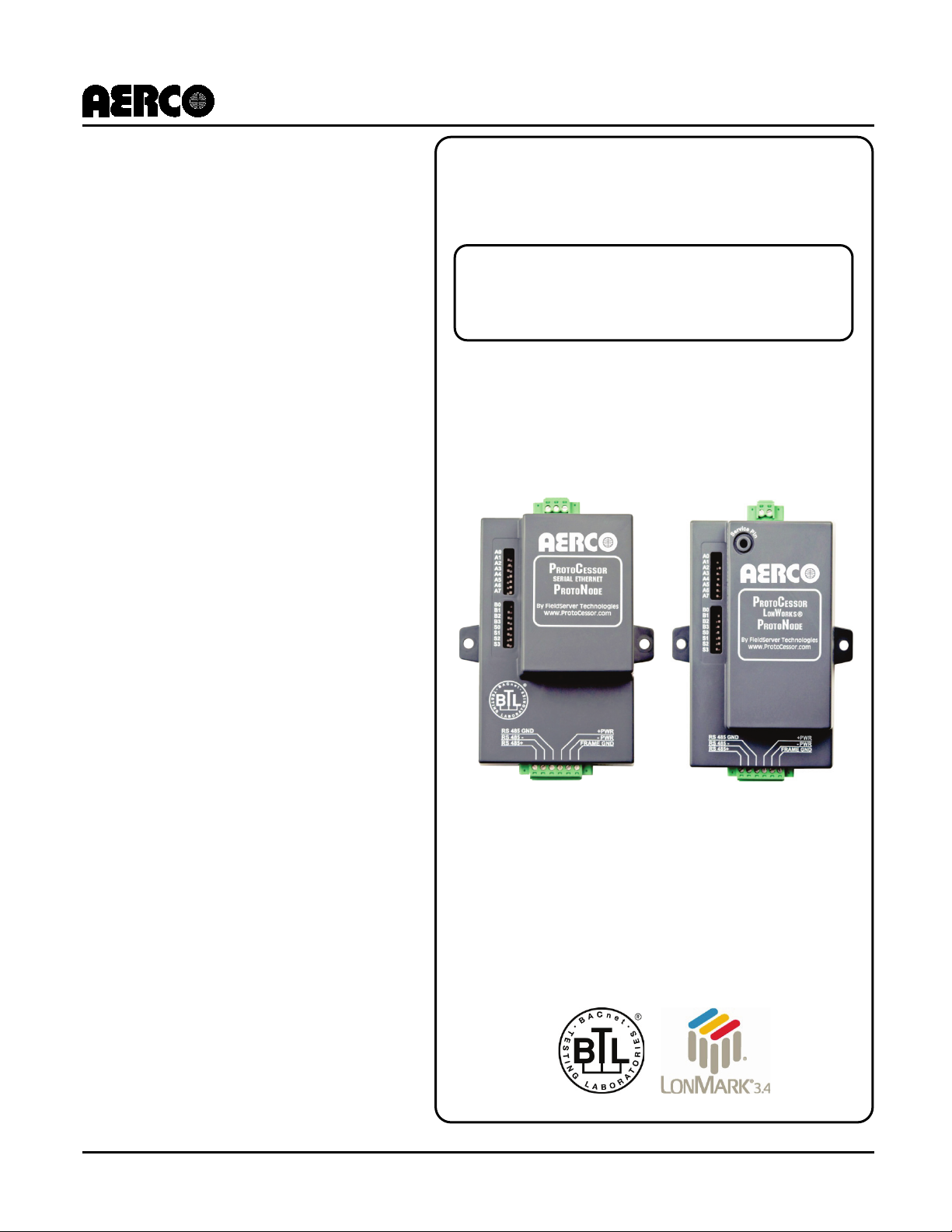
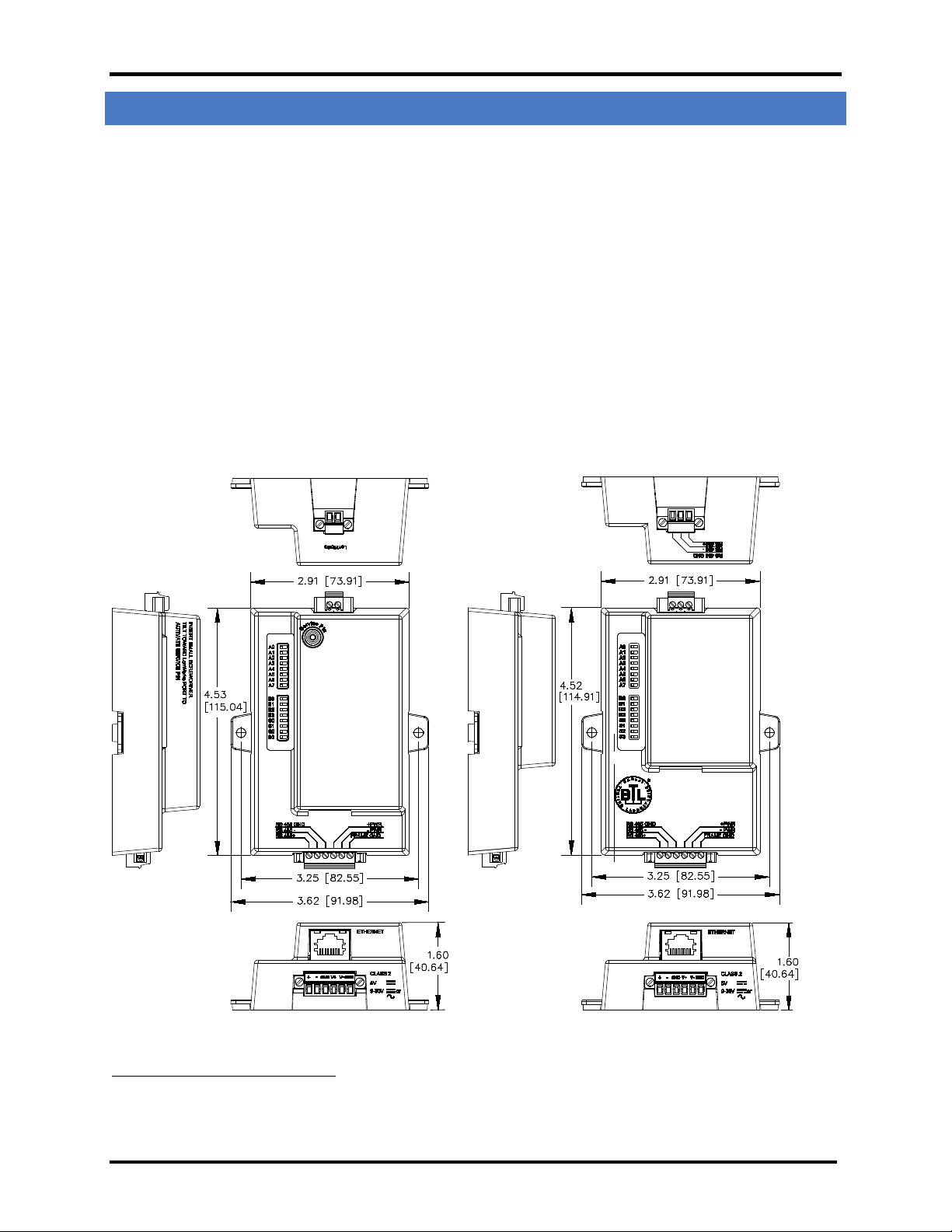
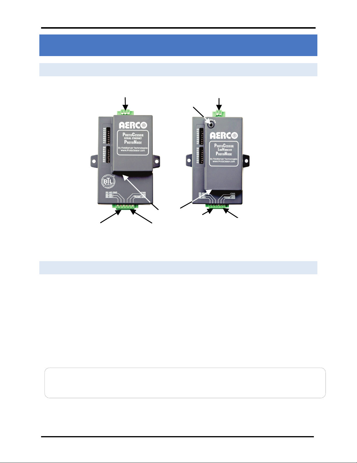
The ProtoNode units feature a very small form factor, as indicated in the dimensional illustration below:
3
. All the different AERCO C-More configurations for the various protocols are stored within
1
MS/TP, BACnet/IP, Metasys®2 N2 by JCI, Modbus
Dimensions for ProtoNode LER (left) and ProtoNode RER (right)
1
BACnet is a registered trademark of ASHRAE
2
Metasys is a registered trademark of Johnson Controls Inc.
3
LonMark is a registered trademark of LonMark International
4
LonWorks is a registered trademark of Echelon Corporation
AERCO International, Inc. • 100 Oritani Dr. • Blauvelt, New York 10913 • Phone: 800-526-0288 VD2:011712
Page 5 of 64
Page 6

USER MANUAL
AERCO/ProtoNode Gateway
OMM-0080_0D
(This page left intentionally blank)
GF-129
AERCO International, Inc. • 100 Oritani Dr. • Blauvelt, New York 10913 • Phone: 800-526-0288 VD2:011712
Page 6 of 64
Page 7
USER MANUAL
AERCO/ProtoNode Gateway
OMM-0080_0D
GF-129
2. BACNET/LONWORKS SETUP THROUGH PROTOCESSOR PROTONODE RER/LER
2.1 Installation Steps For The Customer
1. Set the A, B, and S DIP Switch banks for field protocol baud rate, Node-ID/Device Instance, and proper
configuration. See Section 2.3.
2. Connect the ProtoNode to the Field protocol port and AERCO’s Control System/Boiler Management
System – RS-232 or RS-485 interface. See Section 3.
3. Power up the ProtoNode RER or LER. After power up, the device is installed on BACnet MS/TP, Metasys
N2, or LonWorks for the LER.
4. Where the Field protocol is BACnet/IP, refer to Section 5 to run the Ruinet utility program to change the
IP address. No changes to the configuration file are necessary.
2.2 Record Identification Data
Each ProtoNode has a unique serial number located on the underside of the unit. The number format is FPC-N3XXXX-XXX-XXXX. This number should be recorded as it may be required for technical support. The AERCO part
numbers and model numbers are shown in the table below:
ProtoNode Model AERCO P/N Model Number
RER 64084 FPC-N34-103-126-0645
LER 64085 FPC-N35-103-401-0646
2.3 Configure the DIP Switches
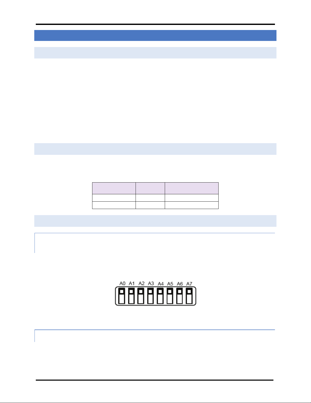
2.3.1 Setting the Node/ID Device Instance (DIP Switch A0 – A7) for BACnet MS/TP, BACnet/IP, and Metasys N2
• The A Bank DIP switches on the ProtoNode RER-R allow users to set the Node-ID/Device Instance
on the Field RS-485.
• DIP switches A0 – A7 can also be used to set the MAC Address for BACnet MS/TP and BACnet/IP
Figure 1. A0 – A7 DIP Switches
• Please refer to Appendix B.2 for the full range of addresses to set Nod-ID/Device Instance..
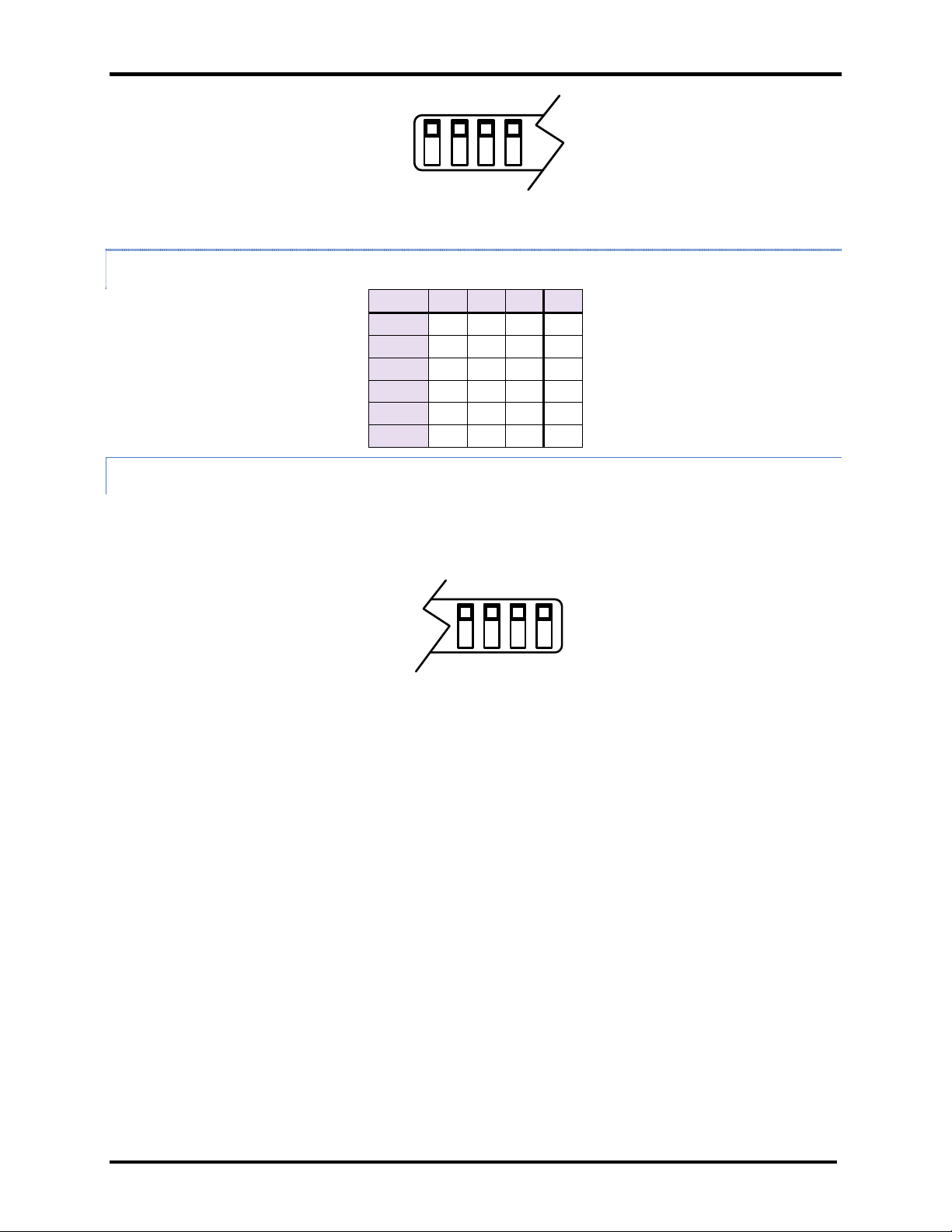
2.3.2 Setting the Serial Baud Rate (DIP Switch B0 – B3) for BACnet MS/TP & Metasys N2
• Setting the serial baud rate to match the baud rate provided by the Building Management
System can be done through DIP Switches B0 – B3 for BACnet MS/TP.
• Metasys N2 is always defaulted to 9600 baud and the B bank is disabled.
AERCO International, Inc. • 100 Oritani Dr. • Blauvelt, New York 10913 • Phone: 800-526-0288 VD2:011712
Page 7 of 64
Page 8
USER MANUAL
AERCO/ProtoNode Gateway
OMM-0080_0D
GF-129
B0 B1 B2 B3
Auto
Off
Off
Off
Off
9600
On
On
On
Off
19200
Off
Off
Off
On
38400
On
On
Off
On
57600
Off
Off
On
On
76800
On
Off
On
On
S0 S1 S2 S3
Figure 2. B0 – B3 DIP Switches
2.3.2.1 Baud Rate DIP Switch Selection
Baud B0 B1 B2 B3
2.3.3 Using S0 – S3 bank of DIP Switches to select and load Configuration Files
• The S bank of DIP switches, S0 - S3 is used to select and load a configuration file from a group of
pretested/preloaded configuration files which are stored in the ProtoNode RER (BACnet MS/TP,
BACnet/IP, Modbus TCP and/or Metasys N2) and LER (LonWorks).
Figure 3. S0 – S3 DIP Switches
AERCO International, Inc. • 100 Oritani Dr. • Blauvelt, New York 10913 • Phone: 800-526-0288 VD2:011712
Page 8 of 64
Page 9

USER MANUAL
AERCO/ProtoNode Gateway
OMM-0080_0D
GF-129
2.3.3.1 ProtoNode RER: S0 – S3 (and A1*) DIP Switch Configuration Settings
S0 S1 S2 S3 A1* Profile
Off Off Off Off Off BACnet/IP/BACnet MS/TP, 1 ACS/BMS II/BMS, 4 C-More Controlled Boilers
Off Off Off Off BACnet/IP/BACnet MS/TP, 1 ACS/BMS II/BMS, 8 C-More Controlled Boilers
On
Off
On On
Off Off
On
Off
On On On
Off Off Off
On
Off
On On
Off Off
On
Off
On On On On
Off Off Off Off
On
Off Off Off BACnet/IP/BACnet MS/TP, 1 ACS/BMS II/BMS, 12 C-More Controlled Boilers
On
Off Off Off BACnet/IP/BACnet MS/TP, 1 ACS/BMS II, 4 Modulex Boilers With BCMs
Off Off BACnet/IP/BACnet MS/TP, 4 ECS/SP Systems
On
Off
On On
Off Off
On
Off
On On On
Off Off Off
Off Off BACnet/IP/BACnet MS/TP, 12 C-More, 6 ECS/SP, 4 Modulex and 2 ACS/BMS II
On
Off Off Metasys N2, 1 ACS/BMS II/BMS, 4 C-More Controlled Boi l ers
Off Off Metasys N2, 1 ACS/BMS II/BMS, 8 C-More Controlled B oi l ers
Off Metasys N2, 1 ACS/BMS II/BMS CS, 12 C-More Controlled Boilers
On
Off Metasys N2, 1 ACS/BMS II, 4 Modulex Boilers with BCMs
On
Off
Off
On On
On On
Off Metasys N2, 4 ECS/SP Systems
On
Off Metasys N2, 12 C-More, 6 ECS/SP, 4 Modulex and 2 ACS/BMS II
On
Off Modbus TCP, 1 ACS/BMS II/BMS, 4 C-More Controlled Boilers
Off Modbus TCP, 1 ACS/BMS II/BMS, 8 C-More Controlled Boilers
Off Modbus TCP, 1 ACS/BMS II/BMS, 12 C-More Controlled Boilers
Off Modbus TCP, 1 ACS/BMS II, 4 Modulex Boilers With BCMs
Modbus TCP, 4 ECS/SP Systems
On
Modbus TCP, 12 C-More, 6 ECS/SP, 4 Modulex an d 2 ACS/BMS II
On
*NOTE:
The first sixteen profiles in the chart above (Section 2.3.3.1) require that DIP
switches A1 through A8 be set to OFF, which is the default setting, so those
switches do not need to be accessed for those configurations (and so are not
shown in the above chart). However, the last two profiles do require that DIP
switch A1 be set to ON, so for those two profiles, DIP Switch A1 needs to be
changed to ON (A2 through A8 remain in the OFF position).
A photograph showing the DIP switch locations inside the unit is on the next page.
AERCO International, Inc. • 100 Oritani Dr. • Blauvelt, New York 10913 • Phone: 800-526-0288 VD2:011712
Page 9 of 64
Page 10
USER MANUAL
AERCO/ProtoNode Gateway
OMM-0080_0D
GF-129
Off
Off
Off
Off
1 ACS/BMS II/BMS, 4 C-More Controlled Boilers
On
Off
Off
Off
1 ACS/BMS II/BMS, 8 C-More Controlled Boilers
Off
On
Off
Off
1 ACS/BMS II/BMS, 12 C-More Controlled Boilers
On
On
Off
Off
1 ACS/BMS II, 4 Modulex Boilers With BCMs
Off
Off
On
Off
4 ECS/SP Systems
On
Off
On
Off
12 C-More, 6 ECS/SP, 4 Modulex and 2 ACS/BMS II
A1 - A8 DIP
S-Bank DIP
ON
OFF
ON
OFF
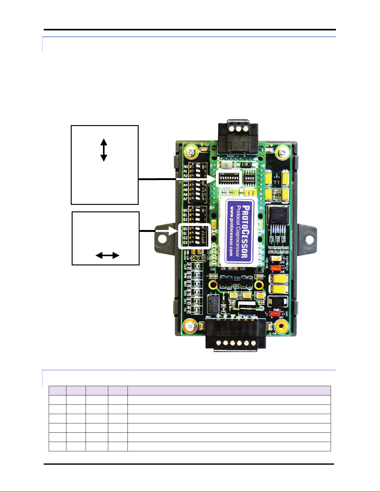
2.3.3.2 ProtoNode RER: S0 – S3 and A1-A8 DIP Switch Locations
The S-Bank DIP switches are accessible through the top cover. However, the cover must be
removed to access the A1 through A8 switches. To remove the cover, pull it from the unit while
holding onto the 6 pin Phoenix connector.
IMPORTANT!
Do not hold the wall mount tabs when removing the cover as these
are designed to break off if not required!
Switches
Switches
(S0, S1, S2, S3)
Location of DIP Switches S0 – S3 and A1-A8
2.3.3.3 ProtoNode LER: S0 – S3 DIP Switch Configuration Settings
S0 S1 S2 S3 Profile
AERCO International, Inc. • 100 Oritani Dr. • Blauvelt, New York 10913 • Phone: 800-526-0288 VD2:011712
Page 10 of 64
Page 11
USER MANUAL
AERCO/ProtoNode Gateway
OMM-0080_0D
GF-129
LonWorks
LonWorks
OEM connection
10/100
10/100
Power +/- and FG
Power +/- and FG
3. INTERFACING THE PROTONODE TO THE AERCO CONTROL SYSTEM (ACS, BMS II, OR
BMS)
3.1 ProtoNode RER and LER showing connection ports
RS-485 Port for Serial
Field Protocol
Service Pin
Port
Base T
RS-485 Port
Base T
(Frame Ground)
9-30 VDC, 12-24 VAC
OEM
Connection
RS-485 Port
(Frame Ground)
9-30 VDC, 12-24 VAC
Figure 4. ProtoNode BACnet RER (left) and LonWorks LER (right)
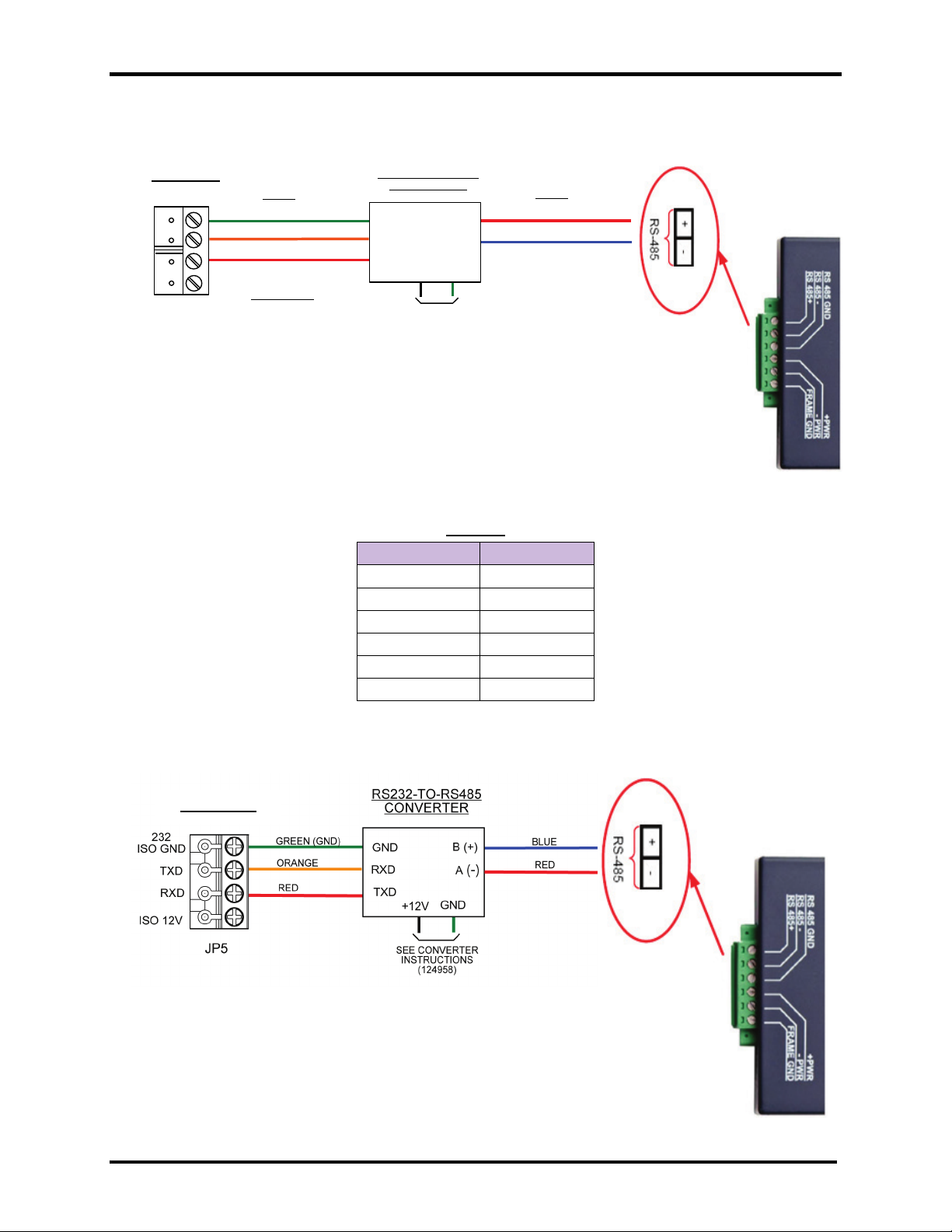
3.2 ACS/BMS II/BMS Wiring Connections to ProtoNode RER and LER
• When an ACS, BMS II, or BMS is being used, an RS-485-to-RS-232 converter will be required to
connect it to the ProtoNode’s RS485 port (green 6-pin Phoenix connector).
• Refer to Figures 5 and 6 to locate the internal RS-232 connector JP12 (BMS) or JP5 (BMS II/ACS) inside
the wiring area of the ACS/BMS II/BMS.
• If the AERCO RS232-to-RS485 Converter (part no. 124943) is used, the RS-232 side of the converter
contains a connector that plugs directly into header connector JP12 (BMS) or JP5 (BMS II/ACS).
• If a third party converter is used, connect the RS-232 Receive (RxD) and Transmit (TxD) wire leads to
the internal RS-232 connector (JP12 or JP5) as shown in Figures 5 and 6. DO NOT connect the wire
shield on this side of the converter.
NOTE
If a third-party RS232-to-RS485 Converter is used, consult the manufacturer’s instruction manual for signal
polarity.
• On the RS-485 side of the converter (Figure 5 to Figure 7), connect the wire leads as follows:
o Connect the TD B (+) terminal to the ProtoNode’s RS485+ Port.
o Connect the TD A (-) terminal to the ProtoNode’s RS485- Port.
o Connect the GND terminal to the ProtoNode’s RS485 Frame GND Port.
AERCO International, Inc. • 100 Oritani Dr. • Blauvelt, New York 10913 • Phone: 800-526-0288 VD2:011712
Page 11 of 64
Page 12
USER MANUAL
AERCO/ProtoNode Gateway
OMM-0080_0D
RXD
TXD
GND
RS232
JP12
RS232-TO-RS485
CONVERTER
TXD
RXD
GND
GND
B (+)
A
(-)
RED (+)
BLUE (-)
GREEN (GND)
RED
ORANGE
IMPORTANT
CHECK INPUT & OUTPUT
POLARITY ON CONVERTER
BEING USED
BMS
RS232
RS485
+12V
SEE CONVERTER
INSTRUCTIONS
(124958)
ACS /BMS
Figure 5. RS-232 Connection to ACS/BMS
GF-129
ACS/BMS II
Pinouts
ProtoNode Pin # Pin assignment
Pin 1 RS-485 +
Pin 2 RS-485 -
Pin 3 RS-485 GND
Pin 4 V +
Pin 5 V -
Pin 6 FRAME GND
Figure 6. RS-232 Connection to ACS/BMS II
AERCO International, Inc. • 100 Oritani Dr. • Blauvelt, New York 10913 • Phone: 800-526-0288 VD2:011712
Page 12 of 64
Page 13
USER MANUAL
AERCO/ProtoNode Gateway
OMM-0080_0D
TERMINATE SHIELD
TIE TOGETHER WITH
TIE TOGETHER WITH
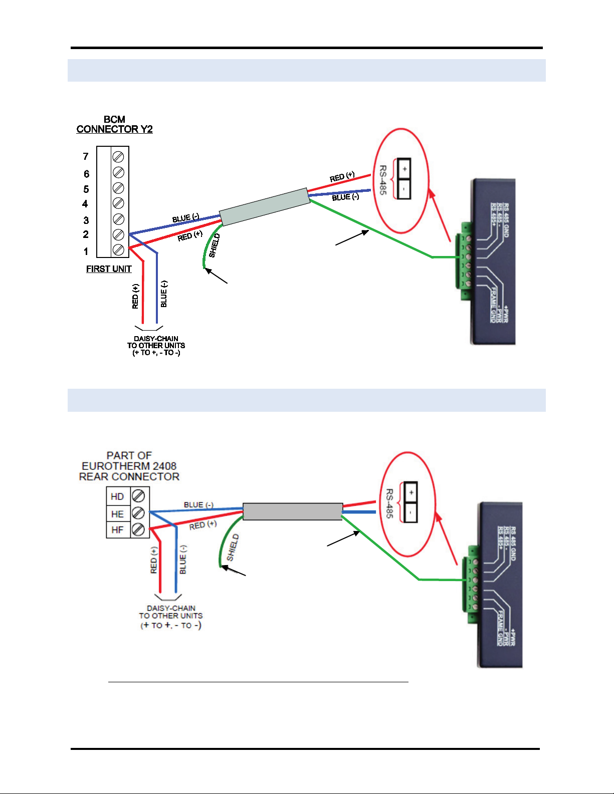
3.3 Modulex BCM
GF-129
3.4 ECS
SHIELDS OF OTHER
FLOAT AT END OF
TO SIGNAL GROUND
UNITS AND
LINE (INSULATE)
Figure 7. RS-485 Connection to BCM
SHIELDS OF OTHER
FLOAT AT END OF
LINE (INSULATE)
Figure 8. RS-485 Connection to ECS
Connect ECS terminals HE and HF to XPC Port 1a (Figures 5-7) as follows:
• Connect the “HF” terminal to the ProtoNode’s “RS485 +” port
• Connect the “HE” terminal to the ProtoNode’s “RS485 -” port
AERCO International, Inc. • 100 Oritani Dr. • Blauvelt, New York 10913 • Phone: 800-526-0288 VD2:011712
TERMINATE SHIELD
TO SIGNAL GROUND
UNITS AND
Page 13 of 64
Page 14
USER MANUAL
AERCO/ProtoNode Gateway
OMM-0080_0D
If an Oxygen Sensor is attached to the C-
ENABLE
DISABLE
BIAS2
TERM
BIAS1
R1
S2
RS485
TIE TOGETHER WITH
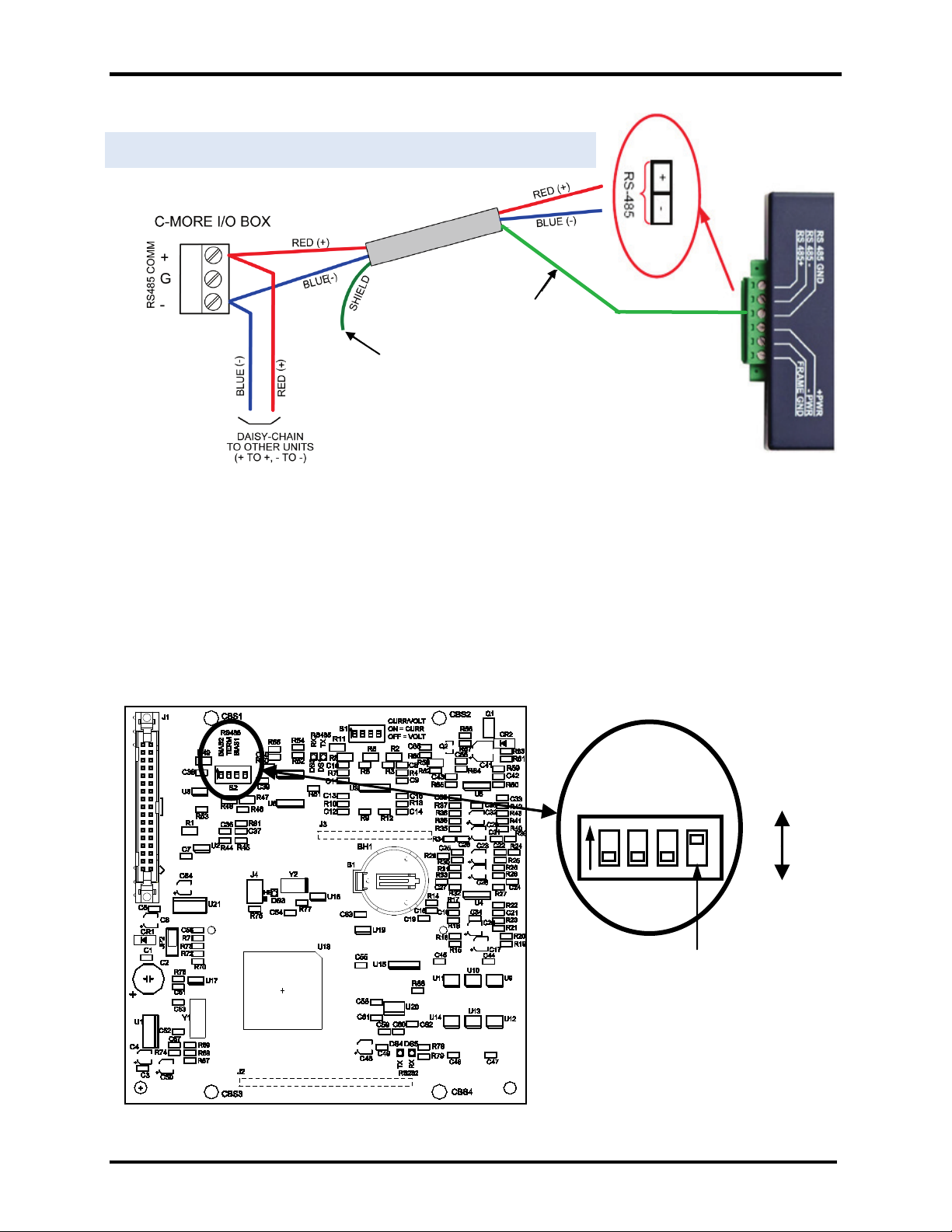
.5 C-MORE
TERMINATE SHIELD
TO SIGNAL GROUND
SHIELDS OF OTHER
UNITS AND
FLOAT AT END OF
LINE (INSULATE)
Figure 8a. RS-485 Connection to C-MORE (RS-485)
GF-129
TERMINATE SHIELD
TO SIGNAL GROUND
IMPORTANT NOTE
The 4-position RS485 DIP Switch (S2) on the PMC PCB of the C-More Controller must be set as
follows:
1) The termination (TERM) and bias (BIAS1 & BIAS2) DIP Switches of S2 must be set to DISABLE.
2) If an Oxygen Sensor is connected to the C-More Controller, switch R1 (see below) should be set
to DISABLED (down). If an Oxygen Sensor is NOT connected to the C-More Controller, it should
be set to ENABLED (up). Improper setting of R1 may result in erro r m essages.
Instructions for accessing the PMC PCB and this DIP Switch can be found in Section 4.3 of ModBus
manual GF-114.
R1
More Controller, set R1 to DISABLED
(down). If an Oxygen Sensor is NOT used,
set R1 to ENABLED (up). Factory default
setting is ENABLED.
C-More Controller PMC PCB
AERCO International, Inc. • 100 Oritani Dr. • Blauvelt, New York 10913 • Phone: 800-526-0288 VD2:011712
Page 14 of 64
Page 15
USER MANUAL
AERCO/ProtoNode Gateway
OMM-0080_0D
G
-
+
4. CONNECTION FROM PROTONODE RER TO BACNET MS/TP AND METASYS N2
NETWORKS
4.1 Wiring the ProtoNode RER to RS-485 Field Protocol
The Field Protocol can be connected to the 3-pin connector on the ProtoNode RER as shown:
GF-129
ProtoNode Pin # Pin assignment
Pin 1 RS-485 +
Pin 2 RS-485 -
Pin 3 RS-485 SIGNAL GND,
MS/TP or N2
Figure 9. Connection from ProtoNode to RS-485 Field Protocol –BACnet MS/TP or Metasys N2
NOTE: For information on connecting the ProtoNode RER to a BACnet/IP network, see Section 5.
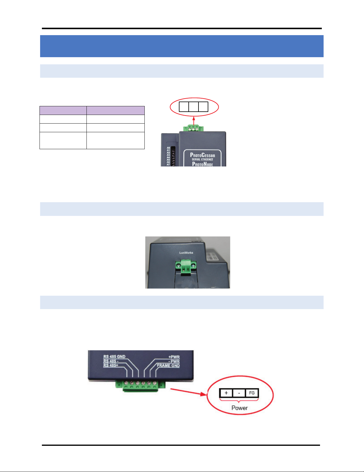
4.2 Wiring the ProtoNode LER Field Port to a LonWorks network
• Connect the ProtoNode to the field network with the LonWorks terminal using a twisted pair non-
shielded cable. LonWorks has no polarity
4.3 Power-Up the ProtoNode RER or LER
Apply power to the device. Ensure that the power supply used complies with the specifications provided in
Appendix B. Ensure that the cable is grounded using the “Frame-GND” terminal.
The ProtoNode features a multi-mode power input and accepts either 9-30 VDC or 12-24 VAC.
Figure 10. Supply Voltage to ProtoNode
AERCO International, Inc. • 100 Oritani Dr. • Blauvelt, New York 10913 • Phone: 800-526-0288 VD2:011712
Page 15 of 64
Page 16
USER MANUAL
AERCO/ProtoNode Gateway
OMM-0080_0D
Pinouts
ProtoNode Pin # Pin assignment
Pin 1 RS-485 +
Pin 2 RS-485 -
Pin 3 RS-485 GND
Pin 4 V +
Pin 5 V -
Pin 6 FRAME GND
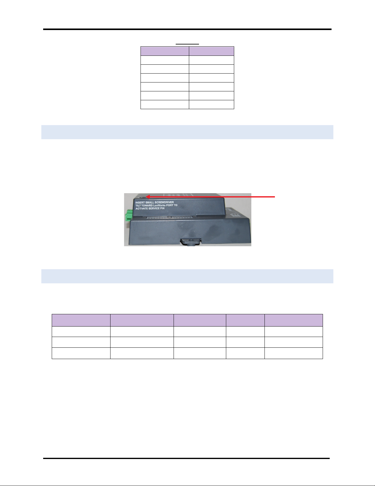
4.4 Commissioning the ProtoNode LER on a Lonworks network
Commissioning may only be performed by the LonWorks administrator.
To commission the ProtoNode LER LonWorks port, insert a small screwdriver in the commissioning hole
on the face of the LER’s enclosure to access the Service Pin. See the illustration on the ProtoNode LER as
to which way to toggle the screw driver during commissioning.
GF-129
4.5 Sending Write Values
The administrator must setup their host management system to write through the gateway to the CMore, ACS or BMS II three or four times within the timeout value.
AERCO Device Parameter Default Value Range Menu
BMS II
C-More
ACS
Network Timeout 30 s 5 to 240 s RS-232
Network Timeout 30 s 5 to 999 s Configuration
Network Timeout 30 s 5 to 240 s RS-232
Refer to GF-112, GF-124, and GF-131 for more information.
LonWorks Service Pin
AERCO International, Inc. • 100 Oritani Dr. • Blauvelt, New York 10913 • Phone: 800-526-0288 VD2:011712
Page 16 of 64
Page 17
USER MANUAL
AERCO/ProtoNode Gateway
OMM-0080_0D
GF-129
5. INSTALL AND RUN THE UTILITY SOFTWARE TO SETUP IP ADDRESS FOR BACNET/IP
• Download the RUINET Utilities from the ProtoCessor web site (under Tech Support – Utilities –
Utilities Software – Install.zip) or access the page at:
http://www.protocessor.com/tech_support/Design_Documents.html#US
• Run Install.zip and follow the installation instructions
• Once installed, the FieldServer Utilities can be located in the Windows Start menu as a desktop icon
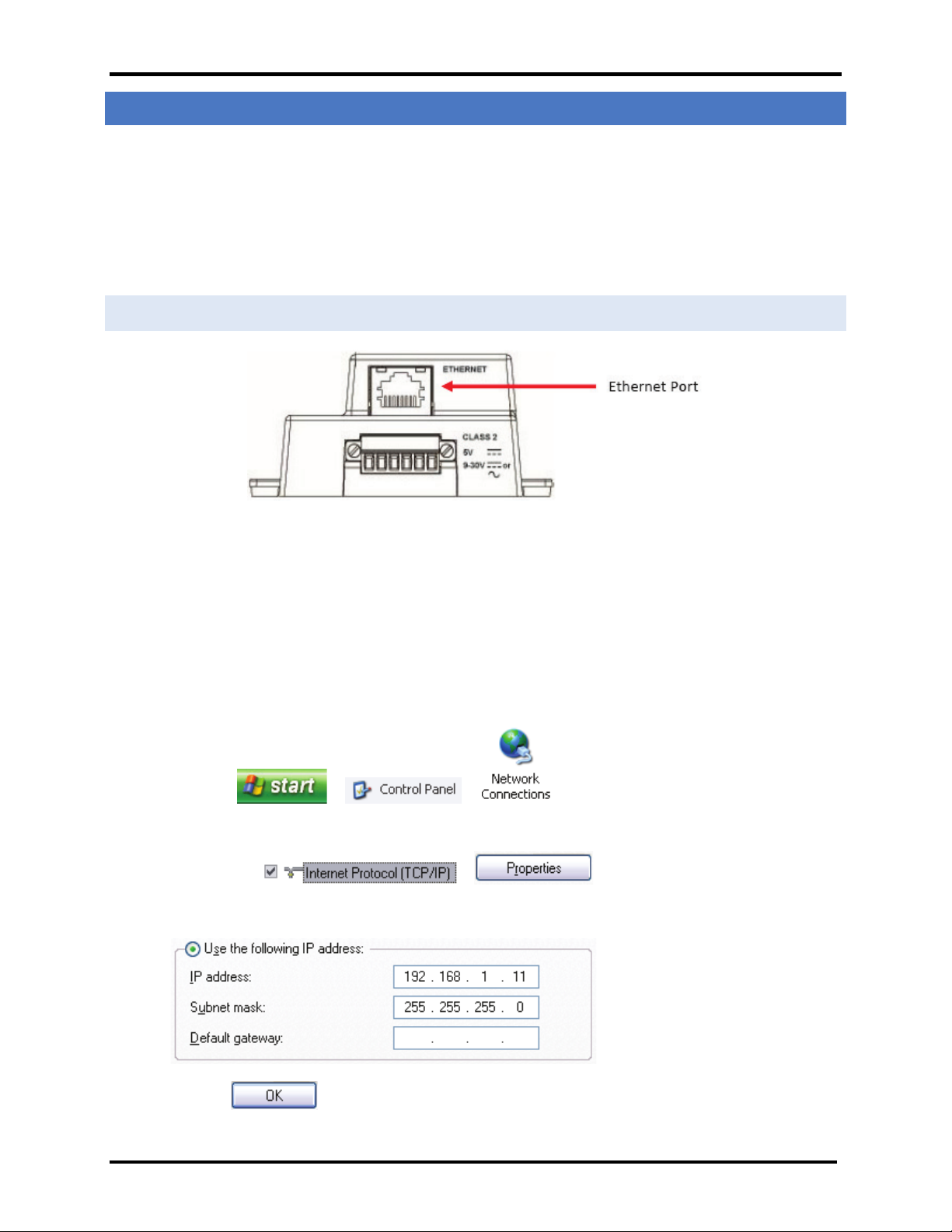
5.1 Connect the PC to the ProtoNode via the Ethernet port
Figure 11. Ethernet port location of ProtoNode
• Disable any wireless Ethernet adapters on the PC/Laptop
• Disable firewall and virus protection software
• Connect a standard cat5 Ethernet cable between the PC and ProtoNode.
• The Default IP Address of the ProtoNode is 192.168.1.24, Subnet Mask is 255.255.255.0. If the PC and
the ProtoNode are on different IP Networks, assign a static IP Address to the PC on the 192.168.1.xxx
network.
• Go to > >
• Right-click on Local Area Connection > Properties
• Highlight >
• Select: Use the following IP address
• Click twice
• Go to Start > Programs > Field Server Utilities > Ruiping Utility
AERCO International, Inc. • 100 Oritani Dr. • Blauvelt, New York 10913 • Phone: 800-526-0288 VD2:011712
Page 17 of 64
Page 18
USER MANUAL
AERCO/ProtoNode Gateway
OMM-0080_0D
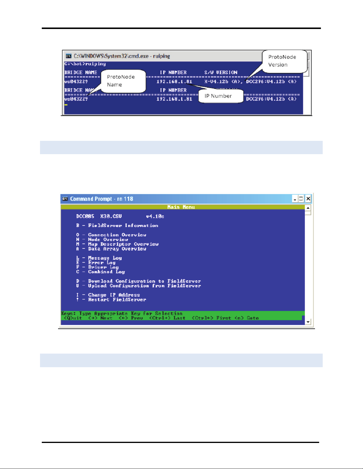
• If the IP Address of the ProtoNode module appears on the screen, the ProtoNode is running.
Figure 12. RUIPING screen
5.2 Connect to the ProtoNode using RUI (Ruinet)
• Double click on the debugging utility, “RUINET” (Remote User Interface). The following screen will
appear: (if Ruinet does not automatically display the main menu, select the ProtoNode by typing the
2-digit number to the left of the title name).
GF-129
5.3 Set IP Address for BACnet/IP
• From the main menu, press “I” to enter the Edit IP Address Settings menu
• Press “1” to modify the IP address of the Ethernet adapter
• Type in a new IP address in the format 192.168.2.X and press <Enter>
• If necessary, press “2” to and change the netmask
• Type in a new Subnet Mask and press <Enter>
AERCO International, Inc. • 100 Oritani Dr. • Blauvelt, New York 10913 • Phone: 800-526-0288 VD2:011712
Figure 13. RUINET screen
Page 18 of 64
Page 19

USER MANUAL
AERCO/ProtoNode Gateway
OMM-0080_0D
• If necessary, press “3” to and change the IP Gateway
• Type in a new IP Gateway and press <Enter>
• Note: If the ProtoNode is connected to a router, the IP Gateway of the ProtoNode should be set to
the IP address of the router that it is connected to
• Unplug Ethernet cable from PC and do not connect to network hub or router.
GF-129
AERCO International, Inc. • 100 Oritani Dr. • Blauvelt, New York 10913 • Phone: 800-526-0288 VD2:011712
Page 19 of 64
Page 20
USER MANUAL
AERCO/ProtoNode Gateway
OMM-0080_0D
GF-129
PWR
TX
RX
ERR
RUN
RTC
Appendix A. TROUBLESHOOTING TIPS
A.1 - LED Diagnostics for Modbus RTU Communications Between the Protonode and AERCO’s Boiler
Controllers
The AERCO/ProtoNode Gateway units feature status LEDs that indicate a number of possible activities. The
ollowing shows how to open the unit and interpret the activity of the indication LEDs.
The lid on top of the AERCO/ProtoNode Gateway must be removed in order to see the LED’s. Pull on the lid while
holding onto the 6 pin Phoenix connector.
IMPORTANT!
Do not hold the wall mount tabs when removi n g the co ver as these are
designed to break off if not required!
LED locations and function descriptions for LER and RER versions are shown in the following two subsections.
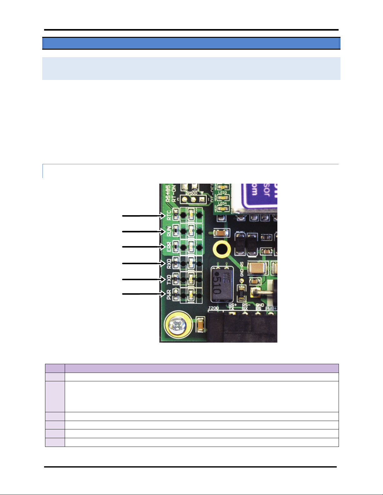
A.1.1 - ProtoNode LER - LED Locations and Functions
Figure 14. AERCO/ProtoNode Gateway LER Main Board Indication LED Locations
LED DESCRIPTION
RUN
ERR
RX
TX
PWR
RTC
The RUN LED will start flashing 20 seconds after power up, indicating normal operation.
The SYS ERR LED will go on solid 15 seconds after power up. It will turn off after 5 seconds. A steady red
light will indicate there is a system error on the ProtoNode LER. If this occurs, immediately report the
related “system error” shown in the error screen of the RUI interface to AERCO International for
evaluation.
The RX LED will flash when a message is received on the socket port.
The TX LED will flash when a message is sent on the socket port.
This is the power light and should show steady green at all times when the ProtoNode LER is powered.
Unused
AERCO International, Inc. • 100 Oritani Dr. • Blauvelt, New York 10913 • Phone: 800-526-0288 VD2:011712
Page 20 of 64
Page 21

USER MANUAL
AERCO/ProtoNode Gateway
OMM-0080_0D
GF-129
The SYS ERR LED will flash once on power up and flash once 15 seconds after power up. A
steady red light will indicate a communication error has occurred. To establish the cause of
On normal operation of ProtoNode LER, the RX LED will flash when a message is received on
ProtoNode is configured for implicit addressing and not
LON TX
LON RX
LON-SRV
Config. Error
System Error
Unused
Unused
Power
Figure 15. AERCO/ProtoNode Gateway LER ProtoCessor Board Indication LED Locations
Run (PIO)
LED DESCRIPTION
Power
System
Error
Comm.
Error
Config.
Error
Node
Offline
RUN
(PIO)
PIC Run
PIC
This is the power light and should show steady green at all times when the ProtoNode LER is
powered.
steady red light will indicate there is a system error on the ProtoNode LER. If this occurs,
immediately report the related “system error” shown in the error screen of the RUI interface
to AERCO International for evaluation.
The COMM ERR LED will flash once on power up and flash once 15 seconds after power up. A
the error, go to the error screen of the RUI interface.
The Config ERR LED will flash once on power up and flash once 15 seconds after power up. A
steady amber light will indicate a configuration error exists in the active configuration. See the
Error Screen in the Remote User Interface for a description of the configuration error.
The Node Offline LED will flash once on power up and flash once 15 seconds after power up. If
the Node Offline LED stays on solid, a Node Offline condition has occurred.
The RUN LED will start flashing 20 seconds after power indicating normal operation. The
ProtoNode LER will be able to access RUINET once this LED starts flashing.
The PIC RUN LED will flash indicating normal operation.
The PIC ERR LED will go on solid indicating there is a PIC error.
Error
LON-TX
LON-RX
LON-
SRV
On normal operation of ProtoNode LER, the TX LED will flash when a message is sent on the
Lon port of the ProtoNode.
the Lon port of the ProtoNode.
The LON-SRV LED will flash if the
commissioned. LED will be off if the ProtoNode is configured for implicit addressing and
commissioned or if it is configured for explicit addressing.
AERCO International, Inc. • 100 Oritani Dr. • Blauvelt, New York 10913 • Phone: 800-526-0288 VD2:011712
Page 21 of 64
Page 22

USER MANUAL
AERCO/ProtoNode Gateway
OMM-0080_0D
Unused
Power
Power
Node
Offline
Config.
Error
Comm.
Error
System
Error
TX
RX
Run
A.1.2 - ProtoNode RER - LED Locations and Functions
Figure 16. AERCO/ProtoNode Gateway RER Indication LED Locations
GF-129
LED DESCRIPTION
PWR
System
Error
Comm.
Error
Config.
Error
Node
Offline
Unused
RX
TX
This is the power light and should show steady green at all times when the ProtoNode RER is
powered.
The SYS ERR LED will go on solid 15 seconds after power up. It will turn off after 5 seconds. A steady
red light will indicate there is a system error on the ProtoCessor. If this occurs, immediately report the
related “system error” shown in the error screen of the RUI interface to AERCO International for
evaluation.
COMM ERR LED will go on solid 15 seconds after power up. It will turn off after 5 seconds. A steady
red light will indicate the communications problem if there is a configured node connected to the
ProtoCessor that is offline. To establish the cause of the error, go to the error screen of the RUI
interface.
Config ERR LED will go on solid 15 seconds after power up. It will turn off after 5 seconds. A steady
amber light will indicate a configuration error exists in the active configuration. See the Error Screen
in the Remote User Interface for a description of the configuration error.
Node Offline LED will go on solid 15 seconds after power up. It will turn off after 5 seconds. If the
Node Offline LED stays on solid, a node offline condition has occurred.
15 seconds after powering up the 4 unused LEDs will turn on solid for 5 seconds, then turn off.
On normal operation of FPC-FD2, the RX LED will flash when a message is received on the field port of
the ProtoCessor.
On normal operation of FPC-FD2, the TX LED will flash when a message is sent on the field port of the
ProtoCessor
Run
RUN LED will flash 20 seconds after power up, signifying normal operation. The ProtoNode RER will be
able to access RUINET once this LED starts flashing. During the first 20 seconds, the LED should be off
AERCO International, Inc. • 100 Oritani Dr. • Blauvelt, New York 10913 • Phone: 800-526-0288 VD2:011712
Page 22 of 64
Page 23

USER MANUAL
AERCO/ProtoNode Gateway
OMM-0080_0D
GF-129
Appendix A.2 - Troubleshooting Procedures for Connection Problems
• Confirm that the network cabling is correct
• Confirm that the computer network card is operational and correctly configured
• Confirm that there is an Ethernet adapter installed in the PC’s Device Manager List, and that it is configured
to run the TCP/IP protocol.
• Check that the IP netmask of the PC matches the ProtoNode. The Default IP Address of the ProtoNode is
192.168.1.24, Subnet Mask is 255.255.255.0
o Go to Start > Run
o Type in “ipconfig”
o The account settings should be displayed
o Ensure that the IP address is 192.168.1.xxx and the netmask 255.255.255.0
• Ensure that the PC and ProtoNode are on the same IP Network, or assign a Static IP Address to the PC on the
192.168.1.0 network using the Remote User Interface Utility.
• If Using Windows XP, ensure that the firewall is disabled
• Ensure that all other Ethernet cards active on the PC, especially wireless adapters are disabled
• Refer to the Field Server Troubleshooting Guide which can be found at www/protocessor.com/downloads/
under documentation
• Confirm that the network cabling is correct
• If write values are lost from time to time, check that the timeout values for the ACS, BMS II, C-More and the
host system are compatible. Refer to Section 4.5 in this manual for more information.
AERCO International, Inc. • 100 Oritani Dr. • Blauvelt, New York 10913 • Phone: 800-526-0288 VD2:011712
Page 23 of 64
Page 24

USER MANUAL
AERCO/ProtoNode Gateway
OMM-0080_0D
(This page left intentionally blank)
GF-129
AERCO International, Inc. • 100 Oritani Dr. • Blauvelt, New York 10913 • Phone: 800-526-0288 VD2:011712
Page 24 of 64
Page 25

USER MANUAL
AERCO/ProtoNode Gateway
OMM-0080_0D
Appendix B. REFERENCE
B.1 Specifications
ProtoNode RER ProtoNode LER
One 6-pin Phoenix connector, one RS-485
+/- ground port, power +/- frame ground
Electrical
Connections
Approvals:
Power
Requirements
Physical
Dimensions
Weight: 0.2 kg (0.4 lbs)
Operating
Temperature:
Surge Suppression EN61000-4-2 ESD EN61000-4-3 EMC EN61000-4-4 EFT
Humidity: 5 - 90% RH (non-condensing)
(Specifications subject to change without notice)
port
One 3-pin RS-485 Phoenix connector, one
RS-485 +/- ground port
One Ethernet-10/100 Ethernet port
CE (EN55022;EN55024; EN60950), UL916, FCC Class A Part 15, DNP3 Conformance Tested,
OPC Self-tested for Compliance, RoHS Compliant, CSA 205 Approved
BTL Marked LonMark Certified
Multi-mode power adapter: 9-30 VDC, 12-24 VAC
11.5 cm L x 8.3 cm W x 4.1 cm H (4.5 x 3.2 x 1.6 in.)
-40°C to 75°C (-40°F to167°F)
One 6-pin Phoenix connector, one RS-485
+/- ground port, power +/- frame ground
port
One Ethernet 10/100 BaseT port
One FTT-10 LonWorks port
GF-129
B.1.1 Compliance with UL Regulations
For UL compliance, the following instructions must be met when operating the ProtoNode.
The units shall be powered by listed LPS or Class 2 power supply suited to the expected operating temperature
range.
The interconnecting power connector and power cable shall:
• Comply with local electrical code.
• Be suited to the expected operating temperature range.
• Meet the current and voltage rating for the ProtoNode/Net
Furthermore, the interconnecting power cable shall:
• not exceed 3.05m (118.3”) in length.
AERCO International, Inc. • 100 Oritani Dr. • Blauvelt, New York 10913 • Phone: 800-526-0288 VD2:011712
Page 25 of 64
Page 26

USER MANUAL
AERCO/ProtoNode Gateway
OMM-0080_0D
GF-129
Off
Off
Off
Off
Off
Off
Off
Off
On
Off
Off
Off
Off
Off
Off
Off
Off
On
Off
Off
Off
Off
Off
Off
On
On
Off
Off
Off
Off
Off
Off
Off
Off
On
Off
Off
Off
Off
Off
On
Off
On
Off
Off
Off
Off
Off
Off
On
On
Off
Off
Off
Off
Off
On
On
On
Off
Off
Off
Off
Off
Off
Off
Off
On
Off
Off
Off
Off
On
Off
Off
On
Off
Off
Off
Off
Off
On
Off
On
Off
Off
Off
Off
On
On
Off
On
Off
Off
Off
Off
12
Off
Off
On
On
Off
Off
Off
Off
On
Off
On
On
Off
Off
Off
Off
Off
On
On
On
Off
Off
Off
Off
On
On
On
On
Off
Off
Off
Off
Off
Off
Off
Off
On
Off
Off
Off
On
Off
Off
Off
On
Off
Off
Off
Off
On
Off
Off
On
Off
Off
Off
On
On
Off
Off
On
Off
Off
Off
Off
Off
On
Off
On
Off
Off
Off
On
Off
On
Off
On
Off
Off
Off
Off
On
On
Off
On
Off
Off
Off
On
On
On
Off
On
Off
Off
Off
Off
Off
Off
On
On
Off
Off
Off
25
On
Off
Off
On
On
Off
Off
Off
Off
On
Off
On
On
Off
Off
Off
27
On
On
Off
On
On
Off
Off
Off
Off
Off
On
On
On
Off
Off
Off
On
Off
On
On
On
Off
Off
Off
Off
On
On
On
On
Off
Off
Off
On
On
On
On
On
Off
Off
Off
Off
Off
Off
Off
Off
On
Off
Off
On
Off
Off
Off
Off
On
Off
Off
Off
On
Off
Off
Off
On
Off
Off
On
On
Off
Off
Off
On
Off
Off
Off
Off
On
Off
Off
On
Off
Off
• Be constructed of materials rated VW-1 or FT-1 or better.
• If the unit is to be installed in an operating environment with a temperature above 65 °C, it should be
installed in a Restricted Access Area requiring a key or a special tool to gain access
• This device must not be connected to a LAN segment with outdoor wiring.
B.2 Address DIP Switch Settings
Address
0
1
2
3
4
5
6
7
8
9
10
11
13
14
15
16
17
18
19
20
21
22
23
24
A0 A1 A2 A3 A4 A5 A6 A7
26
28
29
30
31
32
33
34
35
36
AERCO International, Inc. • 100 Oritani Dr. • Blauvelt, New York 10913 • Phone: 800-526-0288 VD2:011712
Page 26 of 64
Page 27

USER MANUAL
AERCO/ProtoNode Gateway
OMM-0080_0D
On
Off
On
Off
Off
On
Off
Off
Off
On
On
Off
Off
On
Off
Off
On
On
On
Off
Off
On
Off
Off
40
Off
Off
Off
On
Off
On
Off
Off
On
Off
Off
On
Off
On
Off
Off
42
Off
On
Off
On
Off
On
Off
Off
On
On
Off
On
Off
On
Off
Off
Off
Off
On
On
Off
On
Off
Off
On
Off
On
On
Off
On
Off
Off
Off
On
On
On
Off
On
Off
Off
On
On
On
On
Off
On
Off
Off
Off
Off
Off
Off
On
On
Off
Off
On
Off
Off
Off
On
On
Off
Off
Off
On
Off
Off
On
On
Off
Off
On
On
Off
Off
On
On
Off
Off
Off
Off
On
Off
On
On
Off
Off
53
On
Off
On
Off
On
On
Off
Off
Off
On
On
Off
On
On
Off
Off
55
On
On
On
Off
On
On
Off
Off
Off
Off
Off
On
On
On
Off
Off
On
Off
Off
On
On
On
Off
Off
Off
On
Off
On
On
On
Off
Off
On
On
Off
On
On
On
Off
Off
Off
Off
On
On
On
On
Off
Off
On
Off
On
On
On
On
Off
Off
Off
On
On
On
On
On
Off
Off
On
On
On
On
On
On
Off
Off
Off
Off
Off
Off
Off
Off
On
Off
On
Off
Off
Off
Off
Off
On
Off
66
Off
On
Off
Off
Off
Off
On
Off
On
On
Off
Off
Off
Off
On
Off
68
Off
Off
On
Off
Off
Off
On
Off
On
Off
On
Off
Off
Off
On
Off
Off
On
On
Off
Off
Off
On
Off
On
On
On
Off
Off
Off
On
Off
Off
Off
Off
On
Off
Off
On
Off
On
Off
Off
On
Off
Off
On
Off
Off
On
Off
On
Off
Off
On
Off
On
On
Off
On
Off
Off
On
Off
Off
Off
On
On
Off
Off
On
Off
On
Off
On
On
Off
Off
On
Off
Off
On
On
On
Off
Off
On
Off
79
On
On
On
On
Off
Off
On
Off
Off
Off
Off
Off
On
Off
On
Off
81
On
Off
Off
Off
On
Off
On
Off
GF-129
Address
37
38
39
41
43
44
45
46
47
48
49
50
51
52
54
A0 A1 A2 A3 A4 A5 A6 A7
56
57
58
59
60
61
62
63
64
65
67
69
70
71
72
73
74
75
76
77
78
80
AERCO International, Inc. • 100 Oritani Dr. • Blauvelt, New York 10913 • Phone: 800-526-0288 VD2:011712
Page 27 of 64
Page 28

USER MANUAL
AERCO/ProtoNode Gateway
OMM-0080_0D
Off
On
Off
Off
On
Off
On
Off
On
On
Off
Off
On
Off
On
Off
Off
Off
On
Off
On
Off
On
Off
85
On
Off
On
Off
On
Off
On
Off
Off
On
On
Off
On
Off
On
Off
87
On
On
On
Off
On
Off
On
Off
Off
Off
Off
On
On
Off
On
Off
On
Off
Off
On
On
Off
On
Off
Off
On
Off
On
On
Off
On
Off
On
On
Off
On
On
Off
On
Off
Off
Off
On
On
On
Off
On
Off
On
Off
On
On
On
Off
On
Off
Off
On
On
On
On
Off
On
Off
On
On
On
On
On
Off
On
Off
Off
Off
Off
Off
Off
On
On
Off
On
Off
Off
Off
Off
On
On
Off
98
Off
On
Off
Off
Off
On
On
Off
On
On
Off
Off
Off
On
On
Off
100
Off
Off
On
Off
Off
On
On
Off
On
Off
On
Off
Off
On
On
Off
Off
On
On
Off
Off
On
On
Off
On
On
On
Off
Off
On
On
Off
Off
Off
Off
On
Off
On
On
Off
On
Off
Off
On
Off
On
On
Off
Off
On
Off
On
Off
On
On
Off
On
On
Off
On
Off
On
On
Off
Off
Off
On
On
Off
On
On
Off
On
Off
On
On
Off
On
On
Off
Off
On
On
On
Off
On
On
Off
111
On
On
On
On
Off
On
On
Off
Off
Off
Off
Off
On
On
On
Off
113
On
Off
Off
Off
On
On
On
Off
Off
On
Off
Off
On
On
On
Off
On
On
Off
Off
On
On
On
Off
Off
Off
On
Off
On
On
On
Off
On
Off
On
Off
On
On
On
Off
Off
On
On
Off
On
On
On
Off
On
On
On
Off
On
On
On
Off
Off
Off
Off
On
On
On
On
Off
On
Off
Off
On
On
On
On
Off
Off
On
Off
On
On
On
On
Off
On
On
Off
On
On
On
On
Off
124
Off
Off
On
On
On
On
On
Off
On
Off
On
On
On
On
On
Off
126
Off
On
On
On
On
On
On
Off
GF-129
Address
82
83
84
86
88
89
90
91
92
93
94
95
96
97
99
A0 A1 A2 A3 A4 A5 A6 A7
101
102
103
104
105
106
107
108
109
110
112
114
115
116
117
118
119
120
121
122
123
125
AERCO International, Inc. • 100 Oritani Dr. • Blauvelt, New York 10913 • Phone: 800-526-0288 VD2:011712
Page 28 of 64
Page 29

USER MANUAL
AERCO/ProtoNode Gateway
OMM-0080_0D
On
On
On
On
On
On
On
Off
Off
Off
Off
Off
Off
Off
Off
On
On
Off
Off
Off
Off
Off
Off
On
130
Off
On
Off
Off
Off
Off
Off
On
On
On
Off
Off
Off
Off
Off
On
132
Off
Off
On
Off
Off
Off
Off
On
On
Off
On
Off
Off
Off
Off
On
Off
On
On
Off
Off
Off
Off
On
On
On
On
Off
Off
Off
Off
On
Off
Off
Off
On
Off
Off
Off
On
On
Off
Off
On
Off
Off
Off
On
Off
On
Off
On
Off
Off
Off
On
On
On
Off
On
Off
Off
Off
On
Off
Off
On
On
Off
Off
Off
On
On
Off
On
On
Off
Off
Off
On
Off
On
On
On
Off
Off
Off
On
143
On
On
On
On
Off
Off
Off
On
Off
Off
Off
Off
On
Off
Off
On
145
On
Off
Off
Off
On
Off
Off
On
Off
On
Off
Off
On
Off
Off
On
On
On
Off
Off
On
Off
Off
On
Off
Off
On
Off
On
Off
Off
On
On
Off
On
Off
On
Off
Off
On
Off
On
On
Off
On
Off
Off
On
On
On
On
Off
On
Off
Off
On
Off
Off
Off
On
On
Off
Off
On
On
Off
Off
On
On
Off
Off
On
Off
On
Off
On
On
Off
Off
On
On
On
Off
On
On
Off
Off
On
156
Off
Off
On
On
On
Off
Off
On
On
Off
On
On
On
Off
Off
On
158
Off
On
On
On
On
Off
Off
On
On
On
On
On
On
Off
Off
On
Off
Off
Off
Off
Off
On
Off
On
On
Off
Off
Off
Off
On
Off
On
Off
On
Off
Off
Off
On
Off
On
On
On
Off
Off
Off
On
Off
On
Off
Off
On
Off
Off
On
Off
On
On
Off
On
Off
Off
On
Off
On
Off
On
On
Off
Off
On
Off
On
On
On
On
Off
Off
On
Off
On
Off
Off
Off
On
Off
On
Off
On
169
On
Off
Off
On
Off
On
Off
On
Off
On
Off
On
Off
On
Off
On
171
On
On
Off
On
Off
On
Off
On
GF-129
Address
127
128
129
131
133
134
135
136
137
138
139
140
141
142
144
A0 A1 A2 A3 A4 A5 A6 A7
146
147
148
149
150
151
152
153
154
155
157
159
160
161
162
163
164
165
166
167
168
170
AERCO International, Inc. • 100 Oritani Dr. • Blauvelt, New York 10913 • Phone: 800-526-0288 VD2:011712
Page 29 of 64
Page 30

USER MANUAL
AERCO/ProtoNode Gateway
OMM-0080_0D
Off
Off
On
On
Off
On
Off
On
On
Off
On
On
Off
On
Off
On
Off
On
On
On
Off
On
Off
On
175
On
On
On
On
Off
On
Off
On
Off
Off
Off
Off
On
On
Off
On
177
On
Off
Off
Off
On
On
Off
On
Off
On
Off
Off
On
On
Off
On
On
On
Off
Off
On
On
Off
On
Off
Off
On
Off
On
On
Off
On
On
Off
On
Off
On
On
Off
On
Off
On
On
Off
On
On
Off
On
On
On
On
Off
On
On
Off
On
Off
Off
Off
On
On
On
Off
On
On
Off
Off
On
On
On
Off
On
Off
On
Off
On
On
On
Off
On
On
On
Off
On
On
On
Off
On
188
Off
Off
On
On
On
On
Off
On
On
Off
On
On
On
On
Off
On
190
Off
On
On
On
On
On
Off
On
On
On
On
On
On
On
Off
On
Off
Off
Off
Off
Off
Off
On
On
On
Off
Off
Off
Off
Off
On
On
Off
On
Off
Off
Off
Off
On
On
On
On
Off
Off
Off
Off
On
On
Off
Off
On
Off
Off
Off
On
On
On
Off
On
Off
Off
Off
On
On
Off
On
On
Off
Off
Off
On
On
On
On
On
Off
Off
Off
On
On
Off
Off
Off
On
Off
Off
On
On
201
On
Off
Off
On
Off
Off
On
On
Off
On
Off
On
Off
Off
On
On
203
On
On
Off
On
Off
Off
On
On
Off
Off
On
On
Off
Off
On
On
On
Off
On
On
Off
Off
On
On
Off
On
On
On
Off
Off
On
On
On
On
On
On
Off
Off
On
On
Off
Off
Off
Off
On
Off
On
On
On
Off
Off
Off
On
Off
On
On
Off
On
Off
Off
On
Off
On
On
On
On
Off
Off
On
Off
On
On
Off
Off
On
Off
On
Off
On
On
On
Off
On
Off
On
Off
On
On
214
Off
On
On
Off
On
Off
On
On
On
On
On
Off
On
Off
On
On
216
Off
Off
Off
On
On
Off
On
On
GF-129
Address
172
173
174
176
178
179
180
181
182
183
184
185
186
187
189
A0 A1 A2 A3 A4 A5 A6 A7
191
192
193
194
195
196
197
198
199
200
202
204
205
206
207
208
209
210
211
212
213
215
AERCO International, Inc. • 100 Oritani Dr. • Blauvelt, New York 10913 • Phone: 800-526-0288 VD2:011712
Page 30 of 64
Page 31

USER MANUAL
AERCO/ProtoNode Gateway
OMM-0080_0D
On
Off
Off
On
On
Off
On
On
Off
On
Off
On
On
Off
On
On
On
On
Off
On
On
Off
On
On
220
Off
Off
On
On
On
Off
On
On
On
Off
On
On
On
Off
On
On
222
Off
On
On
On
On
Off
On
On
On
On
On
On
On
Off
On
On
Off
Off
Off
Off
Off
On
On
On
On
Off
Off
Off
Off
On
On
On
Off
On
Off
Off
Off
On
On
On
On
On
Off
Off
Off
On
On
On
Off
Off
On
Off
Off
On
On
On
On
Off
On
Off
Off
On
On
On
Off
On
On
Off
Off
On
On
On
On
On
On
Off
Off
On
On
On
Off
Off
Off
On
Off
On
On
On
233
On
Off
Off
On
Off
On
On
On
Off
On
Off
On
Off
On
On
On
235
On
On
Off
On
Off
On
On
On
Off
Off
On
On
Off
On
On
On
On
Off
On
On
Off
On
On
On
Off
On
On
On
Off
On
On
On
On
On
On
On
Off
On
On
On
Off
Off
Off
Off
On
On
On
On
On
Off
Off
Off
On
On
On
On
Off
On
Off
Off
On
On
On
On
On
On
Off
Off
On
On
On
On
Off
Off
On
Off
On
On
On
On
On
Off
On
Off
On
On
On
On
246
Off
On
On
Off
On
On
On
On
On
On
On
Off
On
On
On
On
248
Off
Off
Off
On
On
On
On
On
On
Off
Off
On
On
On
On
On
Off
On
Off
On
On
On
On
On
On
On
Off
On
On
On
On
On
Off
Off
On
On
On
On
On
On
On
Off
On
On
On
On
On
On
Off
On
On
On
On
On
On
On
On
On
On
On
On
On
On
On
GF-129
Address
217
218
219
221
223
224
225
226
227
228
229
230
231
232
234
A0 A1 A2 A3 A4 A5 A6 A7
236
237
238
239
240
241
242
243
244
245
247
249
250
251
252
253
254
255
AERCO International, Inc. • 100 Oritani Dr. • Blauvelt, New York 10913 • Phone: 800-526-0288 VD2:011712
Page 31 of 64
Page 32

USER MANUAL
AERCO/ProtoNode Gateway
OMM-0080_0D
(This page left intentionally blank)
GF-129
AERCO International, Inc. • 100 Oritani Dr. • Blauvelt, New York 10913 • Phone: 800-526-0288 VD2:011712
Page 32 of 64
Page 33

USER MANUAL
AERCO/ProtoNode Gateway
OMM-0080_0D
C-more 1
1
C-more 2
2
C-more 3
3
C-more 5
5
C-more 6
6
C-more 7
7
C-more 8
8
C-more 9
9
C-more 11
11
C-more 12
12
ACS /BMS II/BMS
128
Modulex 1
1
Modulex 3
3
Modulex 4
4
ACS /BMS II/BMS
128
ECS 1
29
30
ECS 3
31
ECS 4
32
ECS 1
17
ECS 2
18
ECS 3
19
ECS 4
20
ECS 5
21
22
Appendix C. CONFIGURATION INFORMATION
C.1 Default Modbus RTU COM Settings for AERCO Controllers
GF-129
Serial Port Setting ACS, BMS II, BMS ECS/SP
BCM
(Modulex)
Baud Rate ≤19200 ≤38.4 9600 9600
Data Bits 8 8 8 8
Stop Bits 1 1 1 1
Parity None None None None
Configuration Controllers
C-more 4
12
C-More
Controllers
&
1 ACS/BMS II/BMS
C-more 10
4
Modulex
Controllers
&
1 ACS/BMS II
Modulex 2
Modbus Default
Address
4
10
2
C-More
4
ECS/SP
ECS 2
For Profiles defined in Section C.2.6, the ECS/SP Modbus default point addresses are defined below.
Configuration Controllers
AERCO International, Inc. • 100 Oritani Dr. • Blauvelt, New York 10913 • Phone: 800-526-0288 VD2:011712
6
ECS/SP
ECS 6
Modbus Default
Address
Page 33 of 64
Page 34

USER MANUAL
AERCO/ProtoNode Gateway
OMM-0080_0D
GF-129
03-Net Remote Setpt
setpt_1 AV:24
data float
3
nviSetpt1
inc count (9)
Input (non-polling)
05-Fire Rate In
boilerload_1
AV:28
data float
5
nvoBlrLoad1
inc count (9)
Output (non-polled)
06-Outlet Temp
localsuptemp_1
AV:29
data float
6
nvoLocSupTmp1
inc count (9)
Output (non-polled)
30012-30013/1
30014-30015/1
30009/2
30017/2
40001/2
30018/2
30003/2
30001/2
30002/2
30012-30013/2
30014-30015/2
30009/3
30017/3
40001/3
30018/3
C.2 BACnet/IP, BACnet MS/TP, Metasys N2, and LonWorks Points List
C.2.1 - Four C- M ores and One ACS/BMS II/BMS
Equipment Point Name Name Read Only BACnet Type:ID N2 Type N2 ID Lon SNVT NAME Lon SNVT Lon Direction ModBus/Unit Addr.
Blr Addr 1
01-Fire Rate Out boilerstate_1
02-Active Setpoint effectsetpt_1
07-Display Code dispcode_1
08-Unit Status unitstat_1
09-Run Cycles runcycles_1
10-Run Hours runhours_1
Blr Addr 2
01-Fire Rate Out boilerstate_2
02-Active Setpoint effectsetpt_2
03-Net Remote Setpt setpt_2 AV:47 data float 13 nviSetpt2 inc count (9) Input (non-polling)
05-Fire Rate In boilerload_2
06-Outlet Temp localsuptemp_2
07-Display Code dispcode_2
08-Unit Status unitstat_2
09-Run Cycles runcycles_2
10-Run Hours runhours_2
Blr Addr 3
01-Fire Rate Out boilerstate_3
02-Active Setpoint effectsetpt_3
03-Net Remote Setpt setpt_3 AV:56 data float 23 nviSetpt3 inc count (9) Input (non-polling)
05-Fire Rate In boilerload_3
AV:26 data float 1 nvoBlrState1 inc count (9) Output (non-polled)
AV:27 data float 2 nvoEffSetpt1 inc count (9) Output (non-polled)
AV:22 data float 7 nvoDispCode1 inc count (9) Output (non-polled)
AV:23 data float 8 nvoUnitStat1 inc count (9) Output (non-polled)
AV:42 data float 9 nvoRunCycles1 51 Output (non-polled)
AV:43 data float 10 nvoRunHours1 51 Output (non-polled)
AV:30 data float 11 nvoBlrState2 inc count (9) Output (non-polled)
AV:46 data float 12 nvoEffSetpt2 inc count (9) Output (non-polled)
AV:50 data float 15 nvoBlrLoad2 inc count (9) Output (non-polled)
AV:51 data float
16 nvoLocSupTmp2 inc count (9) Output (non-polled)
AV:52 data float 17 nvoDispCode2 inc count (9) Output (non-polled)
AV:53 data float 18 nvoUnitStat2 inc count (9) Output (non-polled)
AV:44 data float 19 nvoRunCycles2 51 Output (non-polled)
AV:45 data float 20 nvoRunHours2 51 Output (non-polled)
AV:54 data float 21 nvoBlrState3 inc count (9) Output (non-polled)
AV:55 data float 22 nvoEffSetpt3 inc count (9) Output (non-polled)
AV:60 data float 25 nvoBlrLoad3 inc count (9) Output (non-polled)
30009/1
30017/1
40001/1
30018/1
30003/1
30001/1
30002/1
VD2:011712
AERCO International, Inc. • 100 Oritani Dr. • Blauvelt, New York 10913 • Phone: 800-526-0288
Page 34 of 64
Page 35

USER MANUAL
AERCO/ProtoNode Gateway
OMM-0080_0D
GF-129
30003/3
30001/3
30002/3
30012-30013/3
30014-30015/3
30009/4
30017/4
05-Fire Rate In
boilerload_4
AV:73
data float
35
nvoBlrLoad4
inc count (9)
Output (non-polled)
06-Outlet Temp
localsuptemp_4
AV:65
data float
36
nvoLocSupTmp4
inc count (9)
Output (non-polled)
30012-30013/4
30014-30015/4
30005/128
30006/128
Net Header Set
40005/128
30002/128
30003/128
30011/128
30008/128
30009/128
30017/128
30018/128
30019/128
30020/128
30021/128
C.2.1 - Four C-Mores and One ACS/BMS II/BMS (Cont.)
Equipment Point Name Name Read Only BACnet Type:ID N2 Type N2 ID Lon SNVT NAME Lon SNVT Lon Direction ModBus/Unit Addr.
06-Outlet Temp localsuptemp_3
07-Display Code dispcode_3
08-Unit Status unitstat_3
09-Run Cycles runcycles_3
10-Run Hours runhours_3
Blr Addr 4
01-Fire Rate Out boilerstate_4
02-Active Setpoint effectsetpt_4
03-Net Remote Setpt setpt_4 AV:72 data float 33 nviSetpt4 inc count (9) Input (non-polling)
07-Display Code dispcode_4
08-Unit Status unitstat_4
09-Run Cycles runcycles_4
10-Run Hours runhours_4
BMS Addr 128
01-Fire Rate Out boilerstate_5
02-Header Set Temp effectsetpt_5
03Temp setpt_5
04-Header Temp localsuptemp_5
05-Outside Air Temp localoatemp_5
06-Display Code dispcode_5
07-Num Boilers Fired blrfired_5
08-Num Boilers Online blronline_5
09-Last Blr Fired blrlast_5
10-Boiler 1 Status blr1stat_5
11-Boiler 2 Status blr2stat_5
12-Boiler 3 Status blr3stat_5
13-Boiler 4 Status blr4stat_5
AV:33
AV:61 data float
26 nvoLocSupTmp3 inc count (9) Output (non-polled)
AV:62 data float 27 nvoDispCode3 inc count (9) Output (non-polled)
AV:63 data float 28 nvoUnitStat3 inc count (9) Output (non-polled)
AV:58 data float 29 nvoRunCycles3 51 Output (non-polled)
AV:59 data float 30 nvoRunHours3 51 Output (non-polled)
AV:70 data float 31 nvoBlrState4 inc count (9) Output (non-polled)
AV:71 data float 32 nvoEffSetpt4 inc count (9) Output (non-polled)
AV:66 data float 37 nvoDispCode4 inc count (9) Output (non-polled)
AV:67 data float 38 nvoUnitStat4 inc count (9) Output (non-polled)
AV:68 data float 39 nvoRunCycles4 51 Output (non-polled)
AV:69 data float 40 nvoRunHours4 51 Output (non-polled)
AV:31 data float 41 nvoBlrState inc count (9) Output (non-polled)
AV:32 data float 42 nvoEffSetpt inc count (9) Output (non-polled)
data float
AV:34 data float
43
nviSetpt inc count (9)
Input (non-polling)
44 nvoLocSupTmp inc count (9) Output (non-polled)
AV:35 data float 45 nvoLocOATmp inc count (9) Output (non-polled)
AV:36 data float 46 nvoDispCode inc count (9) Output (non-polled)
AV:37 data float 47 nvoBlrsFired inc count (9) Output (non-polled)
AV:38 data float 48 nvoBlrsOnline inc count (9) Output (non-polled)
AV:39 data float 49 nvoLastBlrFired inc count (9) Output (non-polled)
AV:40 data float 50 nvoBlr1Stat inc count (9) Output (non-polled)
AV:41 data float 51 nvoBlr2Stat inc count (9) Output (non-polled)
AV:48 data float 52 nvoBlr3Stat inc count (9) Output (non-polled)
AV:1 data float 53 nvoBlr4Stat inc count (9) Output (non-polled)
40001/4
30018/4
30003/4
30001/4
30002/4
VD2:011712
AERCO International, Inc. • 100 Oritani Dr. • Blauvelt, New York 10913 • Phone: 800-526-0288
Page 35 of 64
Page 36

USER MANUAL
AERCO/ProtoNode Gateway
OMM-0080_0D
GF-129
30022/128
30023/128
30024/128
30025/128
30026/128
30027/128
30028/128
30029/128
Only
Address
30009/1
30017/1
40001/1
30018/1
30003/1
30001/1
30002/1
30012-30013/1
30014-30015/1
30009/2
30017/2
40001/2
30018/2
30003/2
30001/2
30002/2
30012-30013/2
C.2.1 - Four C-Mores and One ACS/BMS II/BMS (Cont.)
Equipment Point Name Name Read Only BACnet Type:ID N2 Type N2 ID Lon SNVT NAME Lon SNVT Lon Direction ModBus/Unit Addr.
14-Boiler 5 Status blr5stat_5
15-Boiler 6 Status blr6stat_5
16-Boiler 7 Status blr7stat_5
17-Boiler 8 Status blr8stat_5
18-Net Blr 1 Status blr9stat_5
19-Net Blr 2 Status blr10stat_5
20-Net Blr 3 Status blr11stat_5
21-Net Blr 4 Status blr12stat_5
C.2.2 - Eight C - Mores and One ACS/BMS II/BMS
AV:2 data float 54 nvoBlr5Stat inc count (9) Output (non-polled)
AV:3 data float 55 nvoBlr6Stat inc count (9) Output (non-polled)
AV:4 data float 56 nvoBlr7Stat inc count (9) Output (non-polled)
AV:5 data float 57 nvoBlr8Stat inc count (9) Output (non-polled)
AV:6 data float 58 nvoNetBlr1Stat inc count (9) Output (non-polled)
AV:7 data float 59 nvoNetBlr2Stat inc count (9) Output (non-polled)
AV:8 data float 60 nvoNetBlr3Stat inc count (9) Output (non-polled)
AV:9 data float 61 nvoNetBlr4Stat inc count (9) Output (non-polled)
Equipment Point Name Name
Blr Addr 1
Blr Addr 2
01-Fire Rate Out boilerstate_1
02-Active Setpoint effectsetpt_1
03-Net Remote Setpt setpt_1 AV:24 data float 3 nviSetpt1 inc count (9) Input (non-polling)
05-Fire Rate In boilerload_1
06-Outlet Temp localsuptemp_1
07-Display Code dispcode_1
08-Unit Status unitstat_1
09-Run Cycles runcycles_1
10-Run Hours runhours_1
01-Fire Rate Out boilerstate_2
02-Active Setpoint effectsetpt_2
03-Net Remote Setpt setpt_2 AV:47 data float 13 nviSetpt2 inc count (9) Input (non-polling)
05-Fire Rate In boilerload_2
06-Outlet Temp localsuptemp_2
07-Display Code dispcode_2
08-Unit Status unitstat_2
09-Run Cycles runcycles_2
Read
BACnet Type:ID N2 Type N2 ID Lon SNVT NAME Lon SNVT Lon Direction
AV:26 data float 1 nvoBlrState1 inc count (9) Output (non-polled)
AV:27 data float 2 nvoEffSetpt1 inc count (9) Output (non-polled)
AV:28 data float 5 nvoBlrLoad1 inc count (9) Output (non -polled)
AV:29 data float 6 nvoLocSupTmp1 inc count (9) Output (non-polled)
AV:22 data float 7 nvoDispCode1 inc count (9) Output (non -polled)
AV:23 data float 8 nvoUnitStat1 inc count (9) Output (non-polled)
AV:42 data float 9 nvoRunCycles1 51 Output (non-polled)
AV:43 data float 10 nvoRunHours1 51 Output (non-polled)
AV:30 data float 11 nvoBlrState2 inc count (9) Output (non-polled)
AV:46 data float 12 nvoEffSetpt2 inc count (9) Output (non-polled)
AV:50 data float 15 nvoBlrLoad2 inc count (9) Output (non -polled)
AV:51 data float 16 nvoLocSupTmp2 inc count (9) Output (non-polled)
AV:52 data float 17 nvoDispCode2 inc count (9) Output (non -polled)
AV:53 data float 18 nvoUnitStat2 inc count (9) Output (non-polled)
AV:44 data float 19 nvoRunCycles2 51 Output (non-polled)
ModBus/Unit
VD2:011712
AERCO International, Inc. • 100 Oritani Dr. • Blauvelt, New York 10913 • Phone: 800-526-0288
Page 36 of 64
Page 37

USER MANUAL
AERCO/ProtoNode Gateway
OMM-0080_0D
Only
Address
30014-30015/2
30009/3
40001/3
30003/3
30002/3
30014-30015/3
30009/4
40001/4
30003/4
30002/4
30014-30015/4
30009/5
40001/5
30003/5
30002/5
30014-30015/5
30009/6
C.2.2 - Eight C-Mores and One ACS/BMS II/BMS (Cont.)
Equipment Point Name Name
Blr Addr 3
Blr Addr 4
Blr Addr 5
Blr Addr 6
10-Run Hours runhours_2
01-Fire Rate Out boilerstate_3
02-Active Setpoint effectsetpt_3
03-Net Remote Setpt setpt_3 AV:56 data float 23 nviSetpt3 inc count (9) Input (non-polling)
05-Fire Rate In boilerload_3
06-Outlet Temp localsuptemp_3
07-Display Code dispcode_3
08-Unit Status unitstat_3
09-Run Cycles runcycles_3
10-Run Hours runhours_3
01-Fire Rate Out boilerstate_4
02-Active Setpoint effectsetpt_4
03-Net Remote Setpt setpt_4 AV:72 data float 33 nviSetpt4 inc count (9) Input (non-polling)
05-Fire Rate In boilerload_4
06-Outlet Temp localsuptemp_4
07-Display Code dispcode_4
08-Unit Status unitstat_4
09-Run Cycles runcycles_4
10-Run Hours runhours_4
01-Fire Rate Out boilerstate_5
02-Active Setpoint effectsetpt_5
03-Net Remote Setpt setpt_5 AV:82 data float 43 nviSetpt5 inc count (9) Input (non-polling)
05-Fire Rate In boilerload_5
06-Outlet Temp localsuptemp_5
07-Display Code dispcode_5
08-Unit Status unitstat_5
09-Run Cycles runcycles_5
10-Run Hours runhours_5
01-Fire Rate Out boilerstate_6
Read
GF-129
BACnet Type:ID N2 Type N2 ID Lon SNVT NAME Lon SNVT Lon Direction
AV:45 data float 20 nvoRunHours2 51 Output (non-polled)
AV:54 data float 21 nvoBlrState3 inc count (9) Output (non-polled)
AV:55 data float 22 nvoEffSetpt3 inc count (9) Output (non-polled)
AV:60 data float 25 nvoBlrLoad3 inc count (9) Output (non-polled)
AV:61 data float 26 nvoLocSupTmp3 inc count (9) Output (non-polled)
AV:62 data float 27 nvoDispCode3 inc count (9) Output (non-polled)
AV:63 data float 28 nvoUnitStat3 inc count (9) Output (non-polled)
AV:58 data float 29 nvoRunCycles3 51 Output (non-polled)
AV:59 data float 30 nvoRunHours3 51 Output (non -polled)
AV:70 data float 31 nvoBlrState4 inc count (9) Output (non-polled)
AV:71 data float 32 nvoEffSetpt4 inc count (9) Output (non-polled)
AV:73 data float 35 nvoBlrLoad4 inc count (9) Output (non-polled)
AV:65 data float 36 nvoLocSupTmp4 inc count (9) Output (non-polled)
AV:66 data float 37 nvoDispCode4 inc count (9) Output (non-polled)
AV:67 data float 38 nvoUnitStat4 inc count (9) Output (non-polled)
AV:68 data float 39 nvoRunCycles4 51 Output (non-polled)
AV:69 data float 40 nvoRunHours4 51 Output (non -polled)
AV:80 data float 41 nvoBlrState5 inc count (9) Output (non-polled)
AV:81 data float 42 nvoEffSetpt5 inc count (9) Output (non-polled)
AV:74 data float 45 nvoBlrLoad5 inc count (9) Output (non-polled)
AV:75 data float 46 nvoLocSupTmp5 inc count (9) Output (non-polled)
AV:76 data float 47 nvoDispCode5 inc count (9) Output (non-polled)
AV:77 data float 48 nvoUnitStat5 inc count (9) Output (non-polled)
AV:78 data float 49 nvoRunCycles5 51 Output (non-polled)
AV:79 data float 50 nvoRunHours5 51 Output (non -polled)
AV:90 data float 51 nvoBlrState6 inc count (9) Output (non-polled)
ModBus/Unit
30017/3
30018/3
30001/3
30012-30013/3
30017/4
30018/4
30001/4
30012-30013/4
30017/5
30018/5
30001/5
30012-30013/5
VD2:011712
AERCO International, Inc. • 100 Oritani Dr. • Blauvelt, New York 10913 • Phone: 800-526-0288
Page 37 of 64
Page 38

USER MANUAL
AERCO/ProtoNode Gateway
OMM-0080_0D
Only
Address
30017/6
30018/6
30001/6
30012-30013/6
30017/7
30018/7
30001/7
30012-30013/7
30017/8
30018/8
30001/8
30012-30013/8
30006/128
03-Net Header Set
Temp
40005/128
C.2.2 - Eight C-Mores and One ACS/BMS II/BMS (Cont.)
Equipment Point Name Name
Blr Addr 7
Blr Addr 8
BMS Addr 128
02-Active Setpoint effectsetpt_6
03-Net Remote Setpt setpt_6 AV:92 data float 53 nviSetpt6 inc count (9) Input (non-polling)
05-Fire Rate In boilerload_6
06-Outlet Temp localsuptemp_6
07-Display Code dispcode_6
08-Unit Status unitstat_6
09-Run Cycles runcycles_6
10-Run Hours runhours_6
01-Fire Rate Out boilerstate_7
02-Active Setpoint effectsetpt_7
03-Net Remote Setpt setpt_7 AV:102 data float 63 nviSetpt7 inc count (9) Input (non-polling)
05-Fire Rate In boilerload_7
06-Outlet Temp localsuptemp_7
07-Display Code dispcode_7
08-Unit Status unitstat_7
09-Run Cycles runcycles_7
10-Run Hours runhours_7
01-Fire Rate Out boilerstate_8
02-Active Setpoint effectsetpt_8
03-Net Remote Setpt setpt_8 AV:112 data float 73 nviSetpt8 inc count (9) Input (non-polling)
05-Fire Rate In boilerload_8
06-Outlet Temp localsuptemp_8
07-Display Code dispcode_8
08-Unit Status unitstat_8
09-Run Cycles runcycles_8
10-Run Hours runhours_8
01-Fire Rate Out boilerstate_13
02-Header Set Temp effectsetpt_13
setpt_13 AV:33 data float 123 nviSetpt inc count (9) Input (non-polling)
Read
GF-129
BACnet Type:ID N2 Type N2 ID Lon SNVT NAME Lon SNVT Lon Direction
AV:91 data float 52 nvoEffSetpt6 inc count (9) Output (non-polled)
AV:84 data float 55 nvoBlrLoad6 inc count (9) Output (non-polled)
AV:85 data float 56 nvoLocSupTmp6 inc count (9) Output (non-polled)
AV:86 data float 57 nvoDispCode6 inc count (9) Output (non-polled)
AV:87 data float 58 nvoUnitStat6 inc count (9) Output (non-polled)
AV:88 data float 59 nvoRunCycles6 51 Output (non-polled)
AV:89 data float 60 nvoRunHours6 51 Output (non -polled)
AV:100 data float 61 nvoBlrState7 inc count (9) Output (non-polled)
AV:101 data float 62 nvoEffSetpt7 inc count (9) Output (non-polled)
AV:94 data float 65 nvoBlrLoad7 inc count (9) Output (non-polled)
AV:95 data float 66 nvoLocSupTmp7 inc count (9) Output (non-polled)
AV:96 data float 67 nvoDispCode7 inc count (9) Output (non-polled)
AV:97 data float 68 nvoUnitStat7 inc count (9) Output (non-polled)
AV:98 data float 69 nvoRunCycles7 51 Output (non-polled)
AV:99 data float 70 nvoRunHours7 51 Output (non -polled)
AV:110 data float 71 nvoBlrState8 inc count (9) Output (non-polled)
AV:111 data float 72 nvoEffSetpt8 inc count (9) Output (non-polled)
AV:104 data float 75 nvoBlrLoad8 inc count (9) Output (non-polled)
AV:105 data float 76 nvoLocSupTmp8 inc count (9) Output (non-polled)
AV:106 data float 77 nvoDispCode8 inc count (9) Output (non-polled)
AV:107 data float 78 nvoUnitStat8 inc count (9) Output (non-polled)
AV:108 data float 79 nvoRunCycles8 51 Output (non-polled)
AV:109 data float 80 nvoRunHours8 51 Output (non-polled)
AV:31 data float 121 nvoBlrState inc count (9) Output (non-polled)
AV:32 data float 122 nvoEffSetpt inc count (9) Output (non-polled)
ModBus/Unit
40001/6
30003/6
30002/6
30014-30015/6
30009/7
40001/7
30003/7
30002/7
30014-30015/7
30009/8
40001/8
30003/8
30002/8
30014-30015/8
30005/128
VD2:011712
AERCO International, Inc. • 100 Oritani Dr. • Blauvelt, New York 10913 • Phone: 800-526-0288
Page 38 of 64
Page 39

USER MANUAL
AERCO/ProtoNode Gateway
OMM-0080_0D
Only
Address
30002/128
30011/128
30017/128
30019/128
30021/128
30023/128
30025/128
30027/128
30029/128
30031/128
30033/128
C.2.2 - Eight C-Mores and One ACS/BMS II/BMS (Cont.)
Equipment Point Name Name
04-Header Temp
05-Outside Air Temp localoatemp_13
06-Display Code dispcode_13
07-Num Boilers Fired blrfired_13
08-Num Boilers
Online
09-Last Blr Fired blrlast_13
10-Boiler 1 Status blr1stat_13
11-Boiler 2 Status blr2stat_13
12-Boiler 3 Status blr3stat_13
13-Boiler 4 Status blr4stat_13
14-Boiler 5 Status blr5stat_13
15-Boiler 6 Status blr6stat_13
16-Boiler 7 Status blr7stat_13
17-Boiler 8 Status blr8stat_13
18-Net Blr 1 Status blr9stat_13
19-Net Blr 2 Status blr10stat_13
20-Net Blr 3 Status blr11stat_13
21-Net Blr 4 Status blr12stat_13
22-Net Blr 5 Status blr13stat_13
23-Net Blr 6 Status blr14stat_13
24-Net Blr 7 Status blr15stat_13
25-Net Blr 8 Status blr16stat_13
localsuptemp_1
3
blronline_13
Read
GF-129
BACnet Type:ID N2 Type N2 ID Lon SNVT NAME Lon SNVT Lon Direction
AV:34 data float 124 nvoLocSupTmp inc count (9) Output (non-polled)
AV:35 data float 125 nvoLocOATmp inc count (9) Output (non-polled)
AV:36 data float 126 nvoDispCode inc count (9) Output (non-polled)
AV:37 data float 127 nvoBlrsFired inc count (9) Output (non-polled)
AV:38 data float 128 nvoBlrsOnline inc count (9) Output (non-polled)
AV:39 data float 129 nvoLastBlrFired inc count (9) Output (non-polled)
AV:40 data float 130 nvoBlr1Stat inc count (9) Output (non-polled)
AV:41 data float 131 nvoBlr2Stat inc count (9) Output (non-polled)
AV:48 data float 132 nvoBlr3Stat inc count (9) Output (non-polled)
AV:1 data float 133 nvoBlr4Stat inc count (9) Output (non-polled)
AV:2 data float 134 nvoBlr5Stat inc count (9) Output (non-polled)
AV:3 data float 135 nvoBlr6Stat inc count (9) Output (non-polled)
AV:4 data float 136 nvoBlr7Stat inc count (9) Output (non-polled)
AV:5 data float 137 nvoBlr8Stat inc count (9) Output (non-polled)
AV:6 data float 138 nvoNetBlr1Stat inc count (9) Output (non-polled)
AV:7 data float 139 nvoNetBlr2Stat inc count (9) Output (non-polled)
AV:8 data float 140 nvoNetBlr3Stat inc count (9) Output (non-polled)
AV:9 data float 141 nvoNetBlr4Stat inc count (9) Output (non-polled)
AV:10 data float 142 nvoNetBlr5Stat inc count (9) Output (non-polled)
AV:11 data float 143 nvoNetBlr6Stat inc count (9) Output (non-polled)
AV:12 data float 144 nvoNetBlr7Stat inc count (9) Output (non-polled)
AV:13 data float 145 nvoNetBlr8Stat inc count (9) Output (non-polled)
ModBus/Unit
30003/128
30008/128
30009/128
30018/128
30020/128
30022/128
30024/128
30026/128
30028/128
30030/128
30032/128
VD2:011712
AERCO International, Inc. • 100 Oritani Dr. • Blauvelt, New York 10913 • Phone: 800-526-0288
Page 39 of 64
Page 40

USER MANUAL
AERCO/ProtoNode Gateway
OMM-0080_0D
Read
Only
ModBus/Unit
Address
30009/1
30017/1
40001/1
30018/1
30003/1
30001/1
30002/1
30012-30013/1
30014-30015/1
30009/2
30017/2
40001/2
30018/2
30003/2
30001/2
30002/2
30012-30013/2
30014-30015/2
30009/3
30017/3
40001/3
30018/3
30003/3
30001/3
30002/3
30012-30013/3
C.2.3 - Twelve C - Mores and One ACS/BMS II/BMS
GF-129
Equipment Point Name Name
Blr Addr 1
01-Fire Rate Out boilerstate_1
Blr Addr 2
Blr Addr 3
02-Active Setpoint effectsetpt_1
03-Net Remote Setpt setpt_1 AV:24 data float 3 nviSetpt1 inc count (9) Input (non-polling)
05-Fire Rate In boilerload_1
06-Outlet Temp localsuptemp_1
07-Display Code dispcode_1
08-Unit Status unitstat_1
09-Run Cycles runcycles_1
10-Run Hours runhours_1
01-Fire Rate Out boilerstate_2
02-Active Setpoint effectsetpt_2
03-Net Remote Setpt setpt_2 AV:47 data float 13 nviSetpt2 inc count (9) Input (non-polling)
05-Fire Rate In boilerload_2
06-Outlet Temp localsuptemp_2
07-Display Code dispcode_2
08-Unit Status unitstat_2
09-Run Cycles runcycles_2
10-Run Hours runhours_2
01-Fire Rate Out boilerstate_3
02-Active Setpoint effectsetpt_3
03-Net Remote Setpt setpt_3 AV:56 data float 23 nviSetpt3 inc count (9) Input (non-polling)
05-Fire Rate In boilerload_3
06-Outlet Temp localsuptemp_3
07-Display Code dispcode_3
08-Unit Status unitstat_3
09-Run Cycles runcycles_3
BACnet Type:ID N2 Type N2 ID Lon SNVT NAME Lon SNVT Lon Direction
AV:26 data float 1 nvoBlrState1 inc count (9) Output (non-polled)
AV:27 data float 2 nvoEffSetpt1 inc count (9) Output (non-polled)
AV:28 data float 5 nvoBlrLoad1 inc count (9) Output (non-polled)
AV:29 data float 6 nvoLocSupTmp1 inc count (9) Output (non-polled)
AV:22 data float 7 nvoDispCode1 inc count (9) Output (non-polled)
AV:23 data float 8 nvoUnitStat1 inc count (9) Output (non-polled)
AV:42 data float 9 nvoRunCycles1 51 Output (non-polled)
AV:43 data float 10 nvoRunHours1 51 Output (non-polled)
AV:30 data float 11 nvoBlrState2 inc count (9) Output (non-polled)
AV:46 data float 12 nvoEffSetpt2 inc count (9) Output (non-polled)
AV:50 data float 15 nvoBlrLoad2 inc count (9) Output (non-polled)
AV:51 data float 16 nvoLocSupTmp2 inc count (9) Output (non-polled)
AV:52 data float 17 nvoDispCode2 inc count (9) Output (non-polled)
AV:53 data float 18 nvoUnitStat2 inc count (9) Output (non-polled)
AV:44 data float 19 nvoRunCycles2 51 Output (non-polled)
AV:45 data float 20 nvoRunHours2 51 Output (non-polled)
AV:54 data float 21 nvoBlrState3 inc count (9) Output (non-polled)
AV:55 data float 22 nvoEffSetpt3 inc count (9) Output (non-polled)
AV:60 data float 25 nvoBlrLoad3 inc count (9) Output (non-polled)
AV:61 data float 26 nvoLocSupTmp3 inc count (9) Output (non-polled)
AV:62 data float 27 nvoDispCode3 inc count (9) Output (non-polled)
AV:63 data float 28 nvoUnitStat3 inc count (9) Output (non-polled)
AV:58 data float 29 nvoRunCycles3 51 Output (non-polled)
VD2:011712
10-Run Hours runhours_3
AERCO International, Inc. • 100 Oritani Dr. • Blauvelt, New York 10913 • Phone: 800-526-0288
AV:59 data float 30 nvoRunHours3 51 Output (non-polled) 30014-30015/3
Page 40 of 64
Page 41

USER MANUAL
AERCO/ProtoNode Gateway
OMM-0080_0D
Only
Address
30017/4
30018/4
30001/4
30012-30013/4
30017/5
30018/5
30001/5
30012-30013/5
30017/6
30018/6
30001/6
30012-30013/6
C.2.3 - Twelve C-Mores and One ACS/BMS II/BMS (Cont.)
Equipment Point Name Name
Blr Addr 4
Blr Addr 5
Blr Addr 6
01-Fire Rate Out boilerstate_4
02-Active Setpoint effectsetpt_4
03-Net Remote Setpt setpt_4 AV:72 data float 33 nviSetpt4 inc count (9) Input (non-polling)
05-Fire Rate In boilerload_4
06-Outlet Temp localsuptemp_4
07-Display Code dispcode_4
08-Unit Status unitstat_4
09-Run Cycles runcycles_4
10-Run Hours runhours_4
01-Fire Rate Out boilerstate_5
02-Active Setpoint effectsetpt_5
03-Net Remote Setpt setpt_5 AV:82 data float 43 nviSetpt5 inc count (9) Input (non-polling)
05-Fire Rate In boilerload_5
06-Outlet Temp localsuptemp_5
07-Display Code dispcode_5
08-Unit Status unitstat_5
09-Run Cycles runcycles_5
10-Run Hours runhours_5
01-Fire Rate Out boilerstate_6
02-Active Setpoint effectsetpt_6
03-Net Remote Setpt setpt_6 AV:92 data float 53 nviSetpt6 inc count (9) Input (non-polling)
05-Fire Rate In boilerload_6
06-Outlet Temp localsuptemp_6
07-Display Code dispcode_6
08-Unit Status unitstat_6
09-Run Cycles runcycles_6
Read
GF-129
BACnet Type:ID N2 Type N2 ID Lon SNVT NAME Lon SNVT Lon Direction
AV:70 data float 31 nvoBlrState4 inc count (9) Output (non-polled)
AV:71 data float 32 nvoEffSetpt4 inc count (9) Output (non-polled)
AV:73 data float 35 nvoBlrLoad4 inc count (9) Output (non-polled)
AV:65 data float 36 nvoLocSupTmp4 inc count (9) Output (non-polled)
AV:66 data float 37 nvoDispCode4 inc count (9) Output (non-polled)
AV:67 data float 38 nvoUnitStat4 inc count (9) Output (non-polled)
AV:68 data float 39 nvoRunCycles4 51 Output (non-polled)
AV:69 data float 40 nvoRunHours4 51 Output (non-polled)
AV:80 data float 41 nvoBlrState5 inc count (9) Output (non-polled)
AV:81 data float 42 nvoEffSetpt5 inc count (9) Output (non-polled)
AV:74 data float 45 nvoBlrLoad5 inc count (9) Output (non-polled)
AV:75 data float 46 nvoLocSupTmp5 inc count (9) Output (non-polled)
AV:76 data float 47 nvoDispCode5 inc count (9) Output (non-polled)
AV:77 data float 48 nvoUnitStat5 inc count (9) Output (non-polled)
AV:78 data float 49 nvoRunCycles5 51 Output (non-polled)
AV:79 data float 50 nvoRunHours5 51 Output (non-polled)
AV:90 data float 51 nvoBlrState6 inc count (9) Output (non-polled)
AV:91 data float 52 nvoEffSetpt6 inc count (9) Output (non-polled)
AV:84 data float 55 nvoBlrLoad6 inc count (9) Output (non-polled)
AV:85 data float 56 nvoLocSupTmp6 inc count (9) Output (non-polled)
AV:86 data float 57 nvoDispCode6 inc count (9) Output (non-polled)
AV:87 data float 58 nvoUnitStat6 inc count (9) Output (non-polled)
AV:88 data float 59 nvoRunCycles6 51 Output (non-polled)
ModBus/Unit
30009/4
40001/4
30003/4
30002/4
30014-30015/4
30009/5
40001/5
30003/5
30002/5
30014-30015/5
30009/6
40001/6
30003/6
30002/6
VD2:011712
10-Run Hours runhours_6
AERCO International, Inc. • 100 Oritani Dr. • Blauvelt, New York 10913 • Phone: 800-526-0288
AV:89 data float 60 nvoRunHours6 51 Output (non-polled)
30014-30015/6
Page 41 of 64
Page 42

USER MANUAL
AERCO/ProtoNode Gateway
OMM-0080_0D
Only
Address
30017/7
30018/7
30001/7
30012-30013/7
30017/8
30018/8
30001/8
30012-30013/8
30017/9
30018/9
30001/9
30012-30013/9
C.2.3 - Twelve C-Mores and One ACS/BMS II/BMS (Cont.)
Equipment Point Name Name
Blr Addr 7
Blr Addr 8
Blr Addr 9
01-Fire Rate Out boilerstate_7
02-Active Setpoint effectsetpt_7
03-Net Remote Setpt setpt_7 AV:102 data float 63 nviSetpt7 inc count (9) Input (non-polling)
05-Fire Rate In boilerload_7
06-Outlet Temp localsuptemp_7
07-Display Code dispcode_7
08-Unit Status unitstat_7
09-Run Cycles runcycles_7
10-Run Hours runhours_7
01-Fire Rate Out boilerstate_8
02-Active Setpoint effectsetpt_8
03-Net Remote Setpt setpt_8 AV:112 data float 73 nviSetpt8 inc count (9) Input (non-polling)
05-Fire Rate In boilerload_8
06-Outlet Temp localsuptemp_8
07-Display Code dispcode_8
08-Unit Status unitstat_8
09-Run Cycles runcycles_8
10-Run Hours runhours_8
01-Fire Rate Out boilerstate_9
02-Active Setpoint effectsetpt_9
03-Net Remote Setpt setpt_9 AV:122 data float 83 nviSetpt9 inc count (9) Input (non-polling)
05-Fire Rate In boilerload_9
06-Outlet Temp localsuptemp_9
07-Display Code dispcode_9
08-Unit Status unitstat_9
09-Run Cycles runcycles_9
Read
GF-129
BACnet Type:ID N2 Type N2 ID Lon SNVT NAME Lon SNVT Lon Direction
AV:100 data float 61 nvoBlrState7 inc count (9) Output (non-polled)
AV:101 data float 62 nvoEffSetpt7 inc count (9) Output (non-polled)
AV:94 data float 65 nvoBlrLoad7 inc count (9) Output (non-polled)
AV:95 data float 66 nvoLocSupTmp7 inc count (9) Output (non-polled)
AV:96 data float 67 nvoDispCode7 inc count (9) Output (non-polled)
AV:97 data float 68 nvoUnitStat7 inc count (9) Output (non-polled)
AV:98 data float 69 nvoRunCycles7 51 Output (non-polled)
AV:99 data float 70 nvoRunHours7 51 Output (non-polled)
AV:110 data float 71 nvoBlrState8 inc count (9) Output (non-polled)
AV:111 data float 72 nvoEffSetpt8 inc count (9) Output (non-polled)
AV:104 data float 75 nvoBlrLoad8 inc count (9) Output (non-polled)
AV:105 data float 76 nvoLocSupTmp8 inc count (9) Output (non-polled)
AV:106 data float 77 nvoDispCode8 inc count (9) Output (non-polled)
AV:107 data float 78 nvoUnitStat8 inc count (9) Output (non-polled)
AV:108 data float 79 nvoRunCycles8 51 Output (non-polled)
AV:109 data float 80 nvoRunHours8 51 Output (non-polled)
AV:120 data float 81 nvoBlrState9 inc count (9) Output (non-polled)
AV:121 data float 82 nvoEffSetpt9 inc count (9) Output (non-polled)
AV:114 data float 85 nvoBlrLoad9 inc count (9) Output (non-polled)
AV:115 data float 86 nvoLocSupTmp9 inc count (9) Output (non-polled)
AV:116 data float 87 nvoDispCode9 inc count (9) Output (non-polled)
AV:117 data float 88 nvoUnitStat9 inc count (9) Output (non-polled)
AV:118 data float 89 nvoRunCycles9 51 Output (non-polled)
ModBus/Unit
30009/7
40001/7
30003/7
30002/7
30014-30015/7
30009/8
40001/8
30003/8
30002/8
30014-30015/8
30009/9
40001/9
30003/9
30002/9
VD2:011712
10-Run Hours runhours_9
AERCO International, Inc. • 100 Oritani Dr. • Blauvelt, New York 10913 • Phone: 800-526-0288
AV:119 data float 90 nvoRunHours9 51 Output (non-polled)
30014-30015/9
Page 42 of 64
Page 43

USER MANUAL
AERCO/ProtoNode Gateway
OMM-0080_0D
Only
Address
30017/10
30018/10
30003/10
30001/10
30002/10
30012-30013/10
30014-30015/10
30009/11
30017/11
40001/11
30018/11
30003/11
30001/11
30002/11
30012-30013/11
30014-30015/11
30009/12
30017/12
40001/12
30018/12
30003/12
30001/12
30002/12
30012-30013/12
C.2.3 - Twelve C-Mores and One ACS/BMS II/BMS (Cont.)
Equipment Point Name Name
Blr Addr 10
Blr Addr 11
Blr Addr 12
01-Fire Rate Out boilerstate_10
02-Active Setpoint effectsetpt_10
03-Net Remote Setpt setpt_10 AV:132 data float 93 nviSetpt10 inc count (9) Input (non-polling)
05-Fire Rate In boilerload_10
06-Outlet Temp localsuptemp_10
07-Display Code dispcode_10
08-Unit Status unitstat_10
09-Run Cycles runcycles_10
10-Run Hours runhours_10
01-Fire Rate Out boilerstate_11
02-Active Setpoint effectsetpt_11
03-Net Remote Setpt setpt_11 AV:142 data float 103 nviSetpt11 inc count (9) Input (non-polling)
05-Fire Rate In boilerload_11
06-Outlet Temp localsuptemp_11
07-Display Code dispcode_11
08-Unit Status unitstat_11
09-Run Cycles runcycles_11
10-Run Hours runhours_11
01-Fire Rate Out boilerstate_12
02-Active Setpoint effectsetpt_12
03-Net Remote Setpt setpt_12 AV:152 data float 113 nviSetpt12 inc count (9) Input (non-polling)
05-Fire Rate In boilerload_12
06-Outlet Temp localsuptemp_12
07-Display Code dispcode_12
08-Unit Status unitstat_12
09-Run Cycles runcycles_12
10-Run Hours runhours_12
Read
GF-129
BACnet Type:ID N2 Type N2 ID Lon SNVT NAME Lon SNVT Lon Direction
AV:130 data float 91 nvoBlrState10 inc count (9) Output (non-polled)
AV:131 data float 92 nvoEffSetpt10 inc count (9) Output (non-polled)
AV:124 data float 95 nvoBlrLoad10 inc count (9) Output (non-polled)
AV:125 data float 96 nvoLocSupTmp10 inc count (9) Output (non-polled)
AV:126 data float 97 nvoDispCode10 inc count (9) Output (non-polled)
AV:127 data float 98 nvoUnitStat10 inc count (9) Output (non-polled)
AV:128 data float 99 nvoRunCycles10 51 Output (non-polled)
AV:129 data float 100 nvoRunHours10 51 Output (non-polled)
AV:140 data float 101 nvoBlrState11 inc count (9) Output (non-polled)
AV:141 data float 102 nvoEffSetpt11 inc count (9) Output (non-polled)
AV:134 data float 105 nvoBlrLoad11 inc count (9) Output (non-polled)
AV:135 data float 106 nvoLocSupTmp11 inc count (9) Output (non-polled)
AV:136 data float 107 nvoDispCode11 inc count (9) Output (non-polled)
AV:137 data float 108 nvoUnitStat11 inc count (9) Output (non-polled)
AV:138 data float 109 nvoRunCycles11 51 Output (non -polled)
AV:139 data float 110 nvoRunHours11 51 Output (non-polled)
AV:150 data float 111 nvoBlrState12 inc count (9) Output (non-polled)
AV:151 data float 112 nvoEffSetpt12 inc count (9) Output (non-polled)
AV:144 data float 115 nvoBlrLoad12 inc count (9) Output (non-polled)
AV:145 data float 116 nvoLocSupTmp12 inc count (9) Output (non-polled)
AV:146 data float 117 nvoDispCode12 inc count (9) Output (non-polled)
AV:147 data float 118 nvoUnitStat12 inc count (9) Output (non-polled)
AV:148 data float 119 nvoRunCycles12 51 Output (non -polled)
AV:149 data float 120 nvoRunHours12 51 Output (non-polled)
ModBus/Unit
30009/10
40001/10
30014-30015/12
VD2:011712
AERCO International, Inc. • 100 Oritani Dr. • Blauvelt, New York 10913 • Phone: 800-526-0288
Page 43 of 64
Page 44

USER MANUAL
AERCO/ProtoNode Gateway
OMM-0080_0D
Only
Address
30006/128
03-Net Header Set
Temp
40005/128
30002/128
30011/128
30017/128
30019/128
30021/128
30023/128
30025/128
30027/128
30029/128
30031/128
30033/128
30035/128
30037/128
C.2.3 - Twelve C-Mores and One ACS/BMS II/BMS (Cont.)
Equipment Point Name Name
BMS Addr 128
01-Fire Rate Out boilerstate_13
02-Header Set Temp effectsetpt_13
setpt_13 AV:33 data float 123 nviSetpt inc count (9) Input (non-polling)
04-Header Temp localsuptemp_13
05-Outside Air Temp localoatemp_13
06-Display Code dispcode_13
07-Num Boilers Fired blrfired_13
08-Num Boilers
Online
09-Last Blr Fired blrlast_13
10-Boiler 1 Status blr1stat_13
11-Boiler 2 Status blr2stat_13
12-Boiler 3 Status blr3stat_13
13-Boiler 4 Status blr4stat_13
14-Boiler 5 Status blr5stat_13
15-Boiler 6 Status blr6stat_13
16-Boiler 7 Status blr7stat_13
17-Boiler 8 Status blr8stat_13
18-Net Blr 1 Status blr9stat_13
19-Net Blr 2 Status blr10stat_13
20-Net Blr 3 Status blr11stat_13
21-Net Blr 4 Status blr12stat_13
22-Net Blr 5 Status blr13stat_13
23-Net Blr 6 Status blr14stat_13
24-Net Blr 7 Status blr15stat_13
25-Net Blr 8 Status blr16stat_13
26-Net Blr 9 Status blr17stat_13
27-Net Blr 10 Status blr18stat_13
28-Net Blr 11 Status blr19stat_13
29-Net Blr 12 Status blr20stat_13
blronline_13
Read
GF-129
BACnet Type:ID N2 Type N2 ID Lon SNVT NAME Lon SNVT Lon Direction
AV:31 data float 121 nvoBlrState inc count (9) Output (non-polled)
AV:32 data float 122 nvoEffSetpt inc count (9) Output (non-polled)
AV:34 data float 124 nvoLocSupTmp inc count (9) Output (non-polled)
AV:35 data float 125 nvoLocOATmp inc count (9) Output (non-polled)
AV:36 data float 126 nvoDispCode inc count (9) Output (non-polled)
AV:37 data float 127 nvoBlrsFired inc count (9) Output (non-polled)
AV:38 data float 128 nvoBlrsOnline inc count (9) Output (non-polled)
AV:39 data float 129 nvoLastBlrFired inc count (9) Output (non-polled)
AV:40 data float 130 nvoBlr1Stat inc count (9) Output (non-polled)
AV:41 data float 131 nvoBlr2Stat inc count (9) Output (non-polled)
AV:48 data float 132 nvoBlr3Stat inc count (9) Output (non-polled)
AV:1 data float 133 nvoBlr4Stat inc count (9) Output (non-polled)
AV:2 data float 134 nvoBlr5Stat inc count (9) Output (non-polled)
AV:3 data float 135 nvoBlr6Stat inc count (9) Output (non-polled)
AV:4 data float 136 nvoBlr7Stat inc count (9) Output (non-polled)
AV:5 data float 137 nvoBlr8Stat inc count (9) Output (non-polled)
AV:6 data float 138 nvoNetBlr1Stat inc count (9) Output (non-polled)
AV:7 data float 139 nvoNetBlr2Stat inc count (9) Output (non-polled)
AV:8 data float 140 nvoNetBlr3Stat inc count (9) Output (non-polled)
AV:9 data float 141 nvoNetBlr4Stat inc count (9) Output (non-polled)
AV:10 data float 142 nvoNetBlr5Stat inc count (9) Output (non-polled)
AV:11 data float 143 nvoNetBlr6Stat inc count (9) Output (non-polled)
AV:12 data float 144 nvoNetBlr7Stat inc count (9) Output (non-polled)
AV:13 data float 145 nvoNetBlr8Stat inc count (9) Output (non-polled)
AV:14 data float 146 nvoNetBlr9Stat inc count (9) Output (non-polled)
AV:15 data float 147 nvoNetBlr10Stat inc count (9) Output (non-polled)
AV:16 data float 148 nvoNetBlr11Stat inc count (9) Output (non-polled)
AV:17 data float 149 nvoNetBlr12Stat inc count (9) Output (non-polled)
ModBus/Unit
30005/128
30003/128
30008/128
30009/128
30018/128
30020/128
30022/128
30024/128
30026/128
30028/128
30030/128
30032/128
30034/128
30036/128
VD2:011712
AERCO International, Inc. • 100 Oritani Dr. • Blauvelt, New York 10913 • Phone: 800-526-0288
Page 44 of 64
Page 45

USER MANUAL
AERCO/ProtoNode Gateway
OMM-0080_0D
Read
Only
BACnet
Type:ID
30005/128
30006/128
40005/128
30002/128
30003/128
30011/128
30008/128
30009/128
30017/128
30026/128
30027/128
30028/128
30029/128
41009/1
41019/1
41005/1
40002/1
41201/1
41003/1
40001/1
41004/1
41009/2
41005/2
C.2.4 - Modulex and One ACS/BMS II
GF-129
Equipment Point Name Name
BMS Addr 128
01-Fire Rate Out boilerstate_5
Mlx Addr 1
Mlx Addr 2
02-Header Set Temp effectsetpt_5
03-Net Header Set Temp setpt_5 AV:33 data float 43 nviSetpt inc count (9) Input (non-polling)
04-Header Temp localsuptemp_5
05-Outside Air Temp localoatemp_5
06-Display Code dispcode_5
07-Num Boilers Fired blrfired_5
08-Num Boilers Online blronline_5
09-Last Blr Fired blrlast_5
18-Net Blr 1 Status blr9stat_5
19-Net Blr 2 Status blr10stat_5
20-Net Blr 3 Status blr11stat_5
21-Net Blr 4 Status blr12stat_5
01-Act Mod Lev boilerstate_1
02-Target Setpoint effectsetpt_1
03-Req Outlet Temp setpt_1 AV:136 data float 64 nviMlxSetptRq1 inc count (9) Input (non-polling)
04-Net Direct Drive boilercmd_1 AV:137 data float 65 nviMlxCmd1 inc count (9) Input (non-polling)
05-Mod Lev In boilerload_1
06-Flow Sens Temp localsuptemp_1
07-Display Code dispcode_1
11-Error Code errcode_1
08-Unit Status unitstat_1
09-Ret Flow Temp returntemp_1
01-Act Mod Lev boilerstate_2
02-Target Setpoint effectsetpt_2
03-Req Outlet Temp setpt_2 AV:146 data float 155 nviMlxSetptRq2 inc count (9) Input (non-polling)
04-Net Direct Drive boilercmd_2 AV:147 data float 156 nviMlxCmd2 inc count (9) Input (non-polling)
N2 Type N2 ID Lon SNVT NAME Lon SNVT Lon Direction ModBus/Unit Address
AV:31 data float 41 nvoBlrState inc count (9) Output (non-polled)
AV:32 data float 42 nvoEffSetpt inc count (9) Output (non-polled)
AV:34 data float 44 nvoLocSupTmp inc count (9) Output (non-polled)
AV:35 data float 45 nvoLocOATmp inc count (9) Output (non-polled)
AV:36 data float 46 nvoDispCode inc count (9) Output (non-polled)
AV:37 data float 47 nvoBlrsFired inc count (9) Output (non-polled)
AV:38 data float 48 nvoBlrsOnline inc count (9) Output (non-polled)
AV:39 data float 49 nvoLastBlrFired inc count (9) Output (non-polled)
AV:26 data float 58 nvoNetBlr1Stat inc count (9) Output (non-polled)
AV:27 data float 59 nvoNetBlr2Stat inc count (9) Output (non-polled)
AV:47 data float 60 nvoNetBlr3Stat inc count (9) Output (non-polled)
AV:49 data float 61 nvoNetBlr4Stat inc count (9) Output (non-polled)
AV:134 data float 62 nvoMlxState1 inc count (9) Output (non-polled)
AV:135 data float 63 nvoMlxSetpt1 inc count (9) Output (non-polled)
AV:138 data float 66 nvoMlxLoad1 inc count (9) Output (non-polled)
AV:139 data float 67 nvoMlxSupTmp1 inc count (9) Output (non-polled)
AV:140 data float 68 nvoMlxDispCode1 inc count (9) Output (non-polled)
AV:1 data float 69 nvoMlxErrCode1 51 Output (non-polled)
AV:141 data float 150 nvoMlxStat1 inc count (9) Output (non-polled)
AV:2 data float 151 nvoMlxRetTmp1 inc count (9) Output (non-polled)
AV:144 data float 153 nvoMlxState2 inc count (9) Output (non-polled)
AV:145 data float 154 nvoMlxSetpt2 inc count (9) Output (non-polled)
30001/1
30002/1
41019/2
40002/2
VD2:011712
AERCO International, Inc. • 100 Oritani Dr. • Blauvelt, New York 10913 • Phone: 800-526-0288
Page 45 of 64
Page 46

USER MANUAL
AERCO/ProtoNode Gateway
OMM-0080_0D
Only
Type:ID
41201/2
30001/2
40001/2
30002/2
41004/2
41009/3
41019/3
41005/3
40002/3
41201/3
41003/3
30001/3
40001/3
30002/3
41004/3
41009/4
41019/4
41005/4
40002/4
41201/4
41003/4
30001/4
40001/4
30002/4
C.2.4 Modulex and One ACS/BMS II (Cont.)
Equipment Point Name Name
Mlx Addr 3
Mlx Addr 4
05-Mod Lev In boilerload_2
06-Flow Sens Temp localsuptemp_2
07-Display Code dispcode_2
11-Error Code errcode_2
08-Unit Status unitstat_2
09-Ret Flow Temp returntemp_2
01-Act Mod Lev boilerstate_3
02-Target Setpoint effectsetpt_3
03-Req Outlet Temp setpt_3 AV:20 data float 166 nviMlxSetptRq3 inc count (9) Input (non-polling)
04-Net Direct Drive boilercmd_3 AV:21 data float 167 nviMlxCmd3 inc count (9) Input (non-polling)
05-Mod Lev In boilerload_3
06-Flow Sens Temp localsuptemp_3
07-Display Code dispcode_3
11-Error Code errcode_3
08-Unit Status unitstat_3
09-Ret Flow Temp returntemp_3
01-Act Mod Lev boilerstate_4
02-Target Setpoint effectsetpt_4
03-Req Outlet Temp setpt_4 AV:30 data float 177 nviMlxSetptRq4 inc count (9) Input (non-polling)
04-Net Direct Drive boilercmd_4 AV:42 data float 178 nviMlxCmd4 inc count (9) Input (non-polling)
05-Mod Lev In boilerload_4
06-Flow Sens Temp localsuptemp_4
07-Display Code dispcode_4
11-Error Code errcode_4
08-Unit Status unitstat_4
09-Ret Flow Temp returntemp_4
Read
GF-129
BACnet
AV:148 data float 157 nvoMlxLoad2 inc count (9) Output (non-polled)
AV:149 data float 158 nvoMlxSupTmp2 inc count (9) Output (non-polled)
AV:150 data float 159 nvoMlxDispCode2 inc count (9) Output (non-polled)
AV:4 data float 160 nvoMlxErrCode2 51 Output (non-polled)
AV:151 data float 161 nvoMlxStat2 inc count (9) Output (non-polled)
AV:5 data float 162 nvoMlxRetTmp2 inc count (9) Output (non-polled)
AV:18 data float 164 nvoMlxState3 inc count (9) Output (non-polled)
AV:19 data float 165 nvoMlxSetpt3 inc count (9) Output (non-polled)
AV:22 data float 168 nvoMlxLoad3 inc count (9) Output (non-polled)
AV:23 data float 169 nvoMlxSupTmp3 inc count (9) Output (non-polled)
AV:24 data float 170 nvoMlxDispCode3 inc count (9) Output (non-polled)
AV:7 data float 171 nvoMlxErrCode3 51 Output (non-polled)
AV:25 data float 172 nvoMlxStat3 inc count (9) Output (non-polled)
AV:8 data float 173 nvoMlxRetTmp3 inc count (9) Output (non-polled)
AV:28 data float 175 nvoMlxState4 inc count (9) Output (non-polled)
AV:29 data float 176 nvoMlxSetpt4 inc count (9) Output (non-polled)
AV:43 data float 179 nvoMlxLoad4 inc count (9) Output (non-polled)
AV:44 data float 180 nvoMlxSupTmp4 inc count (9) Output (non-polled)
AV:45 data float 181 nvoMlxDispCode4 inc count (9) Output (non-polled)
AV:10 data float 182 nvoMlxErrCode4 51 Output (non-polled)
AV:46 data float 183 nvoMlxStat4 inc count (9) Output (non-polled)
AV:11 data float 184 nvoMlxRetTmp4 inc count (9) Output (non-polled)
N2 Type N2 ID Lon SNVT NAME Lon SNVT Lon Direction ModBus/Unit Address
41003/2
41004/4
VD2:011712
AERCO International, Inc. • 100 Oritani Dr. • Blauvelt, New York 10913 • Phone: 800-526-0288
Page 46 of 64
Page 47

USER MANUAL
AERCO/ProtoNode Gateway
OMM-0080_0D
Read
Only
BACnet
Type:ID
N2
ID
Signal
(9)
(9)
inc count
05-FBk Sensor
Temp
inc count
(9)
06-Over Temp
Alarm
inc count
(9)
inc count
(9)
inc count
inc count
(9)
inc count
(9)
05-FBk Sensor
Temp
inc count
(9)
06-Over Temp
Alarm
inc count
(9)
inc count
(9)
01-Cntl Output
Signal
inc count
(9)
inc count
(9)
inc count
(9)
inc count
(9)
05-FBk Sensor
Temp
inc count
(9)
06-Over Temp
Alarm
inc count
(9)
C.2.5 – ECS/SP
GF-129
Equipment Point Name Name
E Valve Addr 29
01-Cntl Output
02-Setpoint effectsetpt_1
03-RmSetpt rmsetpt_1 AV:81 data float 3 nviEcsSetptRq29
04-Outlet Temp localsuptemp_1
E Valve Addr 30
07-Flow Rate flowrate_1
01-Cntl Output
Signal
02-Setpoint effectsetpt_2
03-RmSetpt rmsetpt_2 AV:4 data float 10 nviEcsSetptRq30
04-Outlet Temp localsuptemp_2
boilerstate_1
localrettemp_1
unitstat_1
boilerstate_2
localrettemp_2
unitstat_2
N2 Type
AV:11 data float 1 nvoEcsState29
AV:80 data float 2 nvoEcsSetpt29
AV:84 data float 4 nvoEcsSupTmp29
AV:1 data float 5 nvoEcsRetTmp29
AV:86 data float 6 nvoEcsStat29
AV:2 data float 7 nvoEcsFlow29
AV:12 data float 8 nvoEcsState30
AV:3 data float 9 nvoEcsSetpt30
AV:5 data float 11 nvoEcsSupTmp30
AV:6 data float 12 nvoEcsRetTmp30
AV:7 data float 13 nvoEcsStat30
Lon SNVT NAME Lon SNVT Lon Direction ModBus/Unit Address
inc count
inc count
inc count
(9)
(9)
inc count
(9)
(9)
Output (non-polled) 30004/29
Output (non-polled) 30006/29
Input (non-polling) 40027/29
Output (non-polled) 30002/29
Output (non-polled) 30290/29
Output (non-polled) 30075/29
Output (non-polled) 30291/29
Output (non-polled) 30004/30
Output (non-polled) 30006/30
Input (non-polling) 40027/30
Output (non-polled) 30002/30
Output (non-polled) 30290/30
Output (non-polled) 30075/30
VD2:011712
E Valve Addr 31
07-Flow Rate flowrate_2
boilerstate_3
02-Setpoint effectsetpt_3
03-RmSetpt rmsetpt_3 AV:151 data float 17 nviEcsSetptRq31
04-Outlet Temp localsuptemp_3
localrettemp_3
unitstat_3
AERCO International, Inc. • 100 Oritani Dr. • Blauvelt, New York 10913 • Phone: 800-526-0288
AV:8 data float 14 nvoEcsFlow30
AV:9 data float 15 nvoEcsState31
AV:150 data float 16 nvoEcsSetpt31
AV:152 data float 18 nvoEcsSupTmp31
AV:153 data float 19 nvoEcsRetTmp31
AV:154 data float 20 nvoEcsStat31
Output (non-polled) 30291/30
Output (non-polled) 30004/31
Output (non-polled) 30006/31
Input (non-polling) 40027/31
Output (non-polled) 30002/31
Output (non-polled) 30290/31
Output (non-polled) 30075/31
Page 47 of 64
Page 48

USER MANUAL
AERCO/ProtoNode Gateway
OMM-0080_0D
Only
Type:ID
ID
01-Cntl Output
Signal
inc count
(9)
inc count
(9)
(9)
06-Over Temp
Alarm
inc count
(9)
inc count
(9)
C.2.5 – ECS/SP (Cont.)
Equipment Point Name Name
E Valve Addr 32
07-Flow Rate flowrate_3
boilerstate_4
Read
GF-129
BACnet
AV:155 data float 21 nvoEcsFlow31
AV:10 data float 22 nvoEcsState32
N2 Type
N2
Lon SNVT NAME Lon SNVT Lon Direction ModBus/Unit Address
inc count
(9)
Output (non-polled) 30291/31
Output (non-polled) 30004/32
02-Setpoint effectsetpt_4
03-RmSetpt rmsetpt_4 AV:159 data float 24 nviEcsSetptRq32
04-Outlet Temp localsuptemp_4
05-FBk Sensor
Temp
07-Flow Rate flowrate_4
localrettemp_4
unitstat_4
AV:158 data float 23 nvoEcsSetpt32
AV:160 data float 25 nvoEcsSupTmp32
AV:161 data float 26 nvoEcsRetTmp32
AV:156 data float 27 nvoEcsStat32
AV:157 data float 28 nvoEcsFlow32
C.2.6 - Twelve C - Mores, Six ECS/SP, Four Modulex and Two ACS/BMS II
Equipment Point Name Name
Read
Only
BACnet
Type:ID
Blr Addr 1
01-Fire Rate Out boilerstate_1
02-Active Setpoint effectsetpt_1
03-Net Remote Setpt setpt_1 AV:3 data float 3 nviSetpt1 inc count (9) Input (non-polling) 40001/1
05-Fire Rate In boilerload_1
06-Outlet Temp localsuptemp_1
AV:1 data float 1 nvoBlrState1 inc count (9) Output (non-polled) 30009/1
AV:2 data float 2 nvoEffSetpt1 inc count (9) Output (non-polled) 30017/1
AV:5 data float 5 nvoBlrLoad1 inc count (9) Output (non-polled) 30018/1
AV:6 data float 6
N2 Type N2 ID
Lon SNVT
NAME
nvoLocSupTmp
1
Output (non-polled) 30006/32
inc count
inc count
(9)
inc count
(9)
Lon SNVT Lon Direction
inc count (9) Output (non-polled) 30003/1
Input (non-polling) 40027/32
Output (non-polled) 30002/32
Output (non-polled) 30290/32
Output (non-polled) 30075/32
Output (non-polled) 30291/32
ModBus/Unit
Address
VD2:011712
07-Display Code dispcode_1
08-Unit Status unitstat_1
09-Run Cycles runcycles_1
10-Run Hours runhours_1
AERCO International, Inc. • 100 Oritani Dr. • Blauvelt, New York 10913 • Phone: 800-526-0288
AV:7 data float 7 nvoDispCode1 inc count (9) Output (non-polled) 30001/1
AV:8 data float 8 nvoUnitStat1 inc count (9) Output (non-polled) 30002/1
AV:9 data float 9 nvoRunCycles1 51 Output (non-polled) 30012-30013/1
AV:10 data float 10 nvoRunHours1 51 Output (non-polled) 30014-30015/1
Page 48 of 64
Page 49

USER MANUAL
AERCO/ProtoNode Gateway
OMM-0080_0D
C.2.6 - Twelve C-Mores, Six ECS/SP, Four Modulex, and Two ACS/BMS II (Cont.)
Equipment Point Name Name
Read
Only
BACnet
Type:ID
Blr Addr 2
N2 Type N2 ID
GF-129
Lon SNVT
NAME
Lon SNVT Lon Direction
ModBus/Unit
Address
Blr Addr 3
01-Fire Rate Out boilerstate_2
02-Active Setpoint effectsetpt_2
03-Net Remote Setpt setpt_2
05-Fire Rate In boilerload_2
06-Outlet Temp localsuptemp_2
07-Display Code dispcode_2
08-Unit Status unitstat_2
09-Run Cycles runcycles_2
10-Run Hours runhours_2
01-Fire Rate Out boilerstate_3
02-Active Setpoint effectsetpt_3
03-Net Remote Setpt setpt_3 AV:23 data float 23 nviSetpt3 inc count (9) Input (non-polling) 40001/3
05-Fire Rate In boilerload_3
06-Outlet Temp localsuptemp_3
AV:11 data float 11 nvoBlrState2 inc count (9) Output (non-polled) 30009/2
AV:12 data float 12 nvoEffSetpt2 inc count (9) Output (non-polled) 30017/2
AV:13 data float 13 nviSetpt2 inc count (9) Input (non-polling) 40001/2
AV:15 data float 15 nvoBlrLoad2 inc count (9) Output (non-polled) 30018/2
AV:16 data float 16
AV:17 data float 17 nvoDispCode2 inc count (9) Output (non-polled) 30001/2
AV:18 data float 18 nvoUnitStat2 inc count (9) Output (non-polled) 30002/2
AV:19 data float 19 nvoRunCycles2 51 Output (non-polled) 30012-30013/2
AV:20 data float 20 nvoRunHours2 51 Output (non-polled) 30014-30015/2
AV:21 data float 21 nvoBlrState3 inc count (9) Output (non-polled) 30009/3
AV:22 data float 22 nvoEffSetpt3 inc count (9) Output (non-polled) 30017/3
AV:25 data float 25 nvoBlrLoad3 inc count (9) Output (non -polled) 30018/3
AV:26 data float 26
nvoLocSupTmp
2
nvoLocSupTmp
3
inc count (9) Output (non-polled) 30003/2
inc count (9) Output (non-polled) 30003/3
VD2:011712
07-Display Code dispcode_3
08-Unit Status unitstat_3
09-Run Cycles runcycles_3
10-Run Hours runhours_3
AERCO International, Inc. • 100 Oritani Dr. • Blauvelt, New York 10913 • Phone: 800-526-0288
AV:27 data float 27 nvoDispCode3 inc count (9) Output (non-polled) 30001/3
AV:28 data float 28 nvoUnitStat3 inc count (9) Output (non-polled) 30002/3
AV:29 data float 29 nvoRunCycles3 51 Output (non-polled) 30012-30013/3
AV:30 data float 30 nvoRunHours3 51 Output (non-polled) 30014-30015/3
Page 49 of 64
Page 50

USER MANUAL
AERCO/ProtoNode Gateway
OMM-0080_0D
C.2.6 - Twelve C-Mores, Six ECS/SP, Four Modulex, and Two ACS/BMS II (Cont.)
Equipment Point Name Name
Read
Only
BACnet
Type:ID
Blr Addr 4
N2 Type N2 ID
GF-129
Lon SNVT
NAME
Lon SNVT Lon Direction
ModBus/Unit
Address
Blr Addr 5
01-Fire Rate Out boilerstate_4
02-Active Setpoint effectsetpt_4
03-Net Remote Setpt setpt_4
05-Fire Rate In boilerload_4
06-Outlet Temp localsuptemp_4
07-Display Code dispcode_4
08-Unit Status unitstat_4
09-Run Cycles runcycles_4
10-Run Hours runhours_4
01-Fire Rate Out boilerstate_5
02-Active Setpoint effectsetpt_5
03-Net Remote Setpt setpt_5 AV:43 data float 43 nviSetpt5 inc count (9) Input (non-polling) 40001/5
05-Fire Rate In boilerload_5
06-Outlet Temp localsuptemp_5
AV:31 data float 31 nvoBlrState4 inc count (9) Output (non-polled) 30009/4
AV:32 data float 32 nvoEffSetpt4 inc count (9) Output (non-polled) 30017/4
AV:33 data float 33 nviSetpt4 inc count (9) Input (non-polling) 40001/4
AV:35 data float 35 nvoBlrLoad4 inc count (9) Output (non-polled) 30018/4
AV:36 data float 36
AV:37 data float 37 nvoDispCode4 inc count (9) Output (non-polled) 30001/4
AV:38 data float 38 nvoUnitStat4 inc count (9) Output (non-polled) 30002/4
AV:39 data float 39 nvoRunCycles4 51 Output (non-polled) 30012-30013/4
AV:40 data float 40 nvoRunHours4 51 Output (non-polled) 30014-30015/4
AV:41 data float 41 nvoBlrState5 inc count (9) Output (non-polled) 30009/5
AV:42 data float 42 nvoEffSetpt5 inc count (9) Output (non-polled) 30017/5
AV:45 data float 45 nvoBlrLoad5 inc count (9) Output (non -polled) 30018/5
AV:46 data float 46
nvoLocSupTmp
4
nvoLocSupTmp
5
inc count (9) Output (non-polled) 30003/4
inc count (9) Output (non-polled) 30003/5
VD2:011712
07-Display Code dispcode_5
08-Unit Status unitstat_5
09-Run Cycles runcycles_5
10-Run Hours runhours_5
AERCO International, Inc. • 100 Oritani Dr. • Blauvelt, New York 10913 • Phone: 800-526-0288
AV:47 data float 47 nvoDispCode5 inc count (9) Output (non-polled) 30001/5
AV:48 data float 48 nvoUnitStat5 inc count (9) Output (non-polled) 30002/5
AV:49 data float 49 nvoRunCycles5 51 Output (non-polled) 30012-30013/5
AV:50 data float 50 nvoRunHours5 51 Output (non-polled) 30014-30015/5
Page 50 of 64
Page 51

USER MANUAL
AERCO/ProtoNode Gateway
OMM-0080_0D
C.2.6 - Twelve C-Mores, Six ECS/SP, Four Modulex, and Two ACS/BMS II (Cont.)
Equipment Point Name Name
Read
Only
BACnet
Type:ID
Blr Addr 6
N2 Type N2 ID
GF-129
Lon SNVT
NAME
Lon SNVT Lon Direction
ModBus/Unit
Address
Blr Addr 7
01-Fire Rate Out boilerstate_6
02-Active Setpoint effectsetpt_6
03-Net Remote Setpt setpt_6 AV:53 data float 53 nviSetpt6 inc count (9) Input (non-polling) 40001/6
05-Fire Rate In boilerload_6
06-Outlet Temp localsuptemp_6
07-Display Code dispcode_6
08-Unit Status unitstat_6
09-Run Cycles runcycles_6
10-Run Hours runhours_6
01-Fire Rate Out boilerstate_7
02-Active Setpoint effectsetpt_7
03-Net Remote Setpt setpt_7 AV:63 data float 63 nviSetpt7 inc count (9) Input (non-polling) 40001/7
05-Fire Rate In boilerload_7
06-Outlet Temp localsuptemp_7
AV:51 data float 51 nvoBlrState6 inc count (9) Output (non-polled) 30009/6
AV:52 data float 52 nvoEffSetpt6 inc count (9) Output (non-polled) 30017/6
AV:55 data float 55 nvoBlrLoad6 inc count (9) Output (non-polled) 30018/6
AV:56 data float 56
AV:57 data float 57 nvoDispCode6 inc count (9) Output (non-polled) 30001/6
AV:58 data float 58 nvoUnitStat6 inc count (9) Output (non-polled) 30002/6
AV:59 data float 59 nvoRunCycles6 51 Output (non-polled) 30012-30013/6
AV:60 data float 60 nvoRunHours6 51 Output (non-polled) 30014-30015/6
AV:61 data float 61 nvoBlrState7 inc count (9) Output (non-polled) 30009/7
AV:62 data float 62 nvoEffSetpt7 inc count (9) Output (non-polled) 30017/7
AV:65 data float 65 nvoBlrLoad7 inc count (9) Output (non -polled) 30018/7
AV:66 data float 66
nvoLocSupTmp
6
nvoLocSupTmp
7
inc count (9) Output (non-polled) 30003/6
inc count (9) Output (non-polled) 30003/7
VD2:011712
07-Display Code dispcode_7
08-Unit Status unitstat_7
09-Run Cycles runcycles_7
10-Run Hours runhours_7
AERCO International, Inc. • 100 Oritani Dr. • Blauvelt, New York 10913 • Phone: 800-526-0288
AV:67 data float 67 nvoDispCode7 inc count (9) Output (non-polled) 30001/7
AV:68 data float 68 nvoUnitStat7 inc count (9) Output (non-polled) 30002/7
AV:69 data float 69 nvoRunCycles7 51 Output (non-polled) 30012-30013/7
AV:70 data float 70 nvoRunHours7 51 Output (non-polled) 30014-30015/7
Page 51 of 64
Page 52

USER MANUAL
AERCO/ProtoNode Gateway
OMM-0080_0D
C.2.6 - Twelve C-Mores, Six ECS/SP, Four Modulex, and Two ACS/BMS II (Cont.)
Equipment Point Name Name
Read
Only
BACnet
Type:ID
Blr Addr 8
N2 Type N2 ID
GF-129
Lon SNVT
NAME
Lon SNVT Lon Direction
ModBus/Unit
Address
Blr Addr 9
01-Fire Rate Out boilerstate_8
02-Active Setpoint effectsetpt_8
03-Net Remote Setpt setpt_8 AV:73 data float 73 nviSetpt8 inc count (9) Input (non-polling) 40001/8
05-Fire Rate In boilerload_8
06-Outlet Temp localsuptemp_8
07-Display Code dispcode_8
08-Unit Status unitstat_8
09-Run Cycles runcycles_8
10-Run Hours runhours_8
01-Fire Rate Out boilerstate_9
02-Active Setpoint effectsetpt_9
03-Net Remote Setpt setpt_9 AV:83 data float 83 nviSetpt9 inc count (9) Input (non-polling) 40001/9
05-Fire Rate In boilerload_9
06-Outlet Temp localsuptemp_9
AV:71 data float 71 nvoBlrState8 inc count (9) Output (non-polled) 30009/8
AV:72 data float 72 nvoEffSetpt8 inc count (9) Output (non-polled) 30017/8
AV:75 data float 75 nvoBlrLoad8 inc count (9) Output (non-polled) 30018/8
AV:76 data float 76
AV:77 data float 77 nvoDispCode8 inc count (9) Output (non-polled) 30001/8
AV:78 data float 78 nvoUnitStat8 inc count (9) Output (non-polled) 30002/8
AV:79 data float 79 nvoRunCycles8 51 Output (non-polled) 30012-30013/8
AV:80 data float 80 nvoRunHours8 51 Output (non-polled) 30014-30015/8
AV:81 data float 81 nvoBlrState9 inc count (9) Output (non-polled) 30009/9
AV:82 data float 82 nvoEffSetpt9 inc count (9) Output (non-polled) 30017/9
AV:85 data float 85 nvoBlrLoad9 inc count (9) Output (non -polled) 30018/9
AV:86 data float 86
nvoLocSupTmp
8
nvoLocSupTmp
9
inc count (9) Output (non-polled) 30003/8
inc count (9) Output (non-polled) 30003/9
VD2:011712
07-Display Code dispcode_9
08-Unit Status unitstat_9
09-Run Cycles runcycles_9
10-Run Hours runhours_9
AERCO International, Inc. • 100 Oritani Dr. • Blauvelt, New York 10913 • Phone: 800-526-0288
AV:87 data float 87 nvoDispCode9 inc count (9) Output (non-polled) 30001/9
AV:88 data float 88 nvoUnitStat9 inc count (9) Output (non-polled) 30002/9
AV:89 data float 89 nvoRunCycles9 51 Output (non-polled) 30012-30013/9
AV:90 data float 90 nvoRunHours9 51 Output (non-polled) 30014-30015/9
Page 52 of 64
Page 53

USER MANUAL
AERCO/ProtoNode Gateway
OMM-0080_0D
C.2.6 - Twelve C-Mores, Six ECS/SP, Four Modulex, and Two ACS/BMS II (Cont.)
Equipment Point Name Name
Read
Only
BACnet
Type:ID
Blr Addr 10
N2 Type N2 ID
GF-129
Lon SNVT
NAME
Lon SNVT Lon Direction
ModBus/Unit
Address
Blr Addr 11
01-Fire Rate Out boilerstate_10
02-Active Setpoint effectsetpt_10
03-Net Remote Setpt setpt_10
05-Fire Rate In boilerload_10
06-Outlet Temp
07-Display Code dispcode_10
08-Unit Status unitstat_10
09-Run Cycles runcycles_10
10-Run Hours runhours_10
01-Fire Rate Out boilerstate_11
02-Active Setpoint effectsetpt_11
03-Net Remote Setpt setpt_11 AV:103 data float 103 nviSetpt11 inc count (9) Input (non-polling) 40001/11
05-Fire Rate In boilerload_11
06-Outlet Temp
07-Display Code dispcode_11
localsuptemp_1
0
localsuptemp_1
1
AV:91 data float 91 nvoBlrState10 inc count (9) Output (non-polled) 30009/10
AV:92 data float 92 nvoEffSetpt10 inc count (9) Output (non-polled) 30017/10
AV:93 data float 93 nviSetpt10 inc count (9) Input (non-polling) 40001/10
AV:95 data float 95 nvoBlrLoad10 inc count (9) Output (non-polled) 30018/10
AV:96 data float 96
AV:97 data float 97
AV:98 data float 98 nvoUnitStat10 inc count (9) Output (non-polled) 30002/10
AV:99 data float 99
AV:100 data float 100
AV:101 data float 101 nvoBlrState11 inc count (9) Output (non-polled) 30009/11
AV:102 data float 102 nvoEffSetpt11 inc count (9) Output (non-polled) 30017/11
AV:105 data float 105 nvoBlrLoad11 inc count (9) Output (non-polled) 30018/11
AV:106 data float 106
AV:107 data float 107
nvoLocSupTmp
10
nvoDispCode1
0
nvoRunCycles1
0
nvoRunHours1
0
nvoLocSupTmp
11
nvoDispCode1
1
inc count (9) Output (non-polled) 30003/10
inc count (9) Output (non-polled) 30001/10
51 Output (non-polled) 30012-30013/10
51 Output (non-polled) 30014-30015/10
inc count (9) Output (non-polled) 30003/11
inc count (9) Output (non-polled) 30001/11
VD2:011712
08-Unit Status unitstat_11
09-Run Cycles runcycles_11
10-Run Hours runhours_11
AERCO International, Inc. • 100 Oritani Dr. • Blauvelt, New York 10913 • Phone: 800-526-0288
AV:108 data float 108 nvoUnitStat11 inc count (9) Output (non-polled) 30002/11
AV:109 data float 109
AV:110 data float 110
nvoRunCycles1
1
nvoRunHours1
1
51 Output (non-polled) 30012-30013/11
51 Output (non-polled) 30014-30015/11
Page 53 of 64
Page 54

USER MANUAL
AERCO/ProtoNode Gateway
OMM-0080_0D
C.2.6 - Twelve C-Mores, Six ECS/SP, Four Modulex, and Two ACS/BMS II (Cont.)
Equipment Point Name Name
Read
Only
BACnet
Type:ID
Blr Addr 12
N2 Type N2 ID
GF-129
Lon SNVT
NAME
Lon SNVT Lon Direction
ModBus/Unit
Address
Mlx Addr 13
01-Fire Rate Out boilerstate_12
02-Active Setpoint effectsetpt_12
03-Net Remote Setpt setpt_12 AV:113 data float 113 nviSetpt12 inc count (9) Input (non-polling) 40001/12
05-Fire Rate In boilerload_12
06-Outlet Temp
07-Display Code dispcode_12
08-Unit Status unitstat_12
09-Run Cycles runcycles_12
10-Run Hours runhours_12
01-Act Mod Lev boilerstate_13
02-Target Setpoint effectsetpt_13
03-Req Outlet Temp setpt_13 AV:123 data float 123
04-Net Direct Drive boilercmd_13 AV:124 data float 124 nviMlxCmd13 inc count (9) Input (non-polling) 40002/13
localsuptemp_1
2
AV:111 data float 111 nvoBlrState12 inc count (9) Output (non-polled) 30009/12
AV:112 data float 112 nvoEffSetpt12 inc count (9) Output (non-polled) 30017/12
AV:115 data float 115 nvoBlrLoad12 inc count (9) Output (non-polled) 30018/12
AV:116 data float 116
AV:117 data float 117
AV:118 data float 118 nvoUnitStat12 inc count (9) Output (non-polled) 30002/12
AV:119 data float 119
AV:120 data float 120
AV:121 data float 121 nvoMlxState13 inc count (9) Output (non-polled) 41009/13
AV:122 data float 122 nvoMlxSetpt13 inc count (9) Output (non-polled) 41019/13
nvoLocSupTmp
12
nvoDispCode1
2
nvoRunCycles1
2
nvoRunHours1
2
nviMlxSetptRq1
3
inc count (9) Output (non-polled) 30003/12
inc count (9) Output (non-polled) 30001/12
51 Output (non-polled) 30012-30013/12
51 Output (non-polled) 30014-30015/12
inc count (9) Input (non-polling) 41005/13
VD2:011712
05-Mod Lev In boilerload_13
06-Flow Sens Temp
07-Display Code dispcode_13
11-Error Code errcode_13
08-Unit Status unitstat_13
localsuptemp_1
3
AERCO International, Inc. • 100 Oritani Dr. • Blauvelt, New York 10913 • Phone: 800-526-0288
AV:125 data float 125 nvoMlxLoad13 inc count (9) Output (non-polled) 41201/13
AV:126 data float 126
AV:127 data float 127
AV:128 data float 128
AV:129 data float 129 nvoMlxStat13 inc count (9) Output (non-polled) 30002/13
nvoMlxSupTmp
13
nvoMlxDispCod
e13
nvoMlxErrCode
13
inc count (9) Output (non-polled) 41003/13
inc count (9) Output (non-polled) 30001/13
51 Output (non-polled) 40001/13
Page 54 of 64
Page 55

USER MANUAL
AERCO/ProtoNode Gateway
OMM-0080_0D
C.2.6 - Twelve C-Mores, Six ECS/SP, Four Modulex, and Two ACS/BMS II (Cont.)
Equipment Point Name Name
09-Ret Flow Temp returntemp_13
Read
Only
BACnet
Type:ID
AV:130 data float 130
Mlx Addr 14
N2 Type N2 ID
GF-129
Lon SNVT
NAME
nvoMlxRetTmp
13
Lon SNVT Lon Direction
inc count (9) Output (non-polled) 41004/13
ModBus/Unit
Address
Mlx Addr 15
01-Act Mod Lev boilerstate_14
02-Target Setpoint effectsetpt_14
03-Req Outlet Temp setpt_14 AV:133 data float 133
04-Net Direct Drive boilercmd_14 AV:134 data float 134 nviMlxCmd14 inc count (9) Input (non-polling) 40002/14
05-Mod Lev In boilerload_14
06-Flow Sens Temp
07-Display Code dispcode_14
11-Error Code errcode_14
08-Unit Status unitstat_14
09-Ret Flow Temp returntemp_14
01-Act Mod Lev boilerstate_15
02-Target Setpoint effectsetpt_15
03-Req Outlet Temp setpt_15 AV:143 data float 143
localsuptemp_1
4
AV:131 data float 131 nvoMlxState14 inc count (9) Output (non-polled) 41009/14
AV:132 data float 132 nvoMlxSetpt14 inc count (9) Output (non-polled) 41019/14
nviMlxSetptRq1
4
AV:135 data float 135 nvoMlxLoad14 inc count (9) Output (non-polled) 41201/14
AV:136 data float 136
AV:137 data float 137
AV:138 data float 138
AV:139 data float 139 nvoMlxStat14 inc count (9) Output (non-polled) 30002/14
AV:140 data float 140
AV:141 data float 141 nvoMlxState15 inc count (9) Output (non-polled) 41009/15
AV:142 data float 142 nvoMlxSetpt15 inc count (9) Output (non-polled) 41019/15
nvoMlxSupTmp
14
nvoMlxDispCod
e14
nvoMlxErrCode
14
nvoMlxRetTmp
14
nviMlxSetptRq1
5
inc count (9) Input (non-polling) 41005/14
inc count (9) Output (non-polled) 41003/14
inc count (9) Output (non-polled) 30001/14
51 Output (non-polled) 40001/14
inc count (9) Output (non-polled) 41004/14
inc count (9) Input (non-polling) 41005/15
VD2:011712
04-Net Direct Drive boilercmd_15 AV:144 data float 144 nviMlxCmd15 inc count (9) Input (non-polling) 40002/15
05-Mod Lev In boilerload_15
06-Flow Sens Temp
07-Display Code dispcode_15
localsuptemp_1
5
AERCO International, Inc. • 100 Oritani Dr. • Blauvelt, New York 10913 • Phone: 800-526-0288
AV:145 data float 145 nvoMlxLoad15 inc count (9) Output (non-polled) 41201/15
AV:146 data float 146
AV:147 data float 147
nvoMlxSupTmp
15
nvoMlxDispCod
e15
inc count (9) Output (non-polled) 41003/15
inc count (9) Output (non-polled) 30001/15
Page 55 of 64
Page 56

USER MANUAL
AERCO/ProtoNode Gateway
OMM-0080_0D
Mlx Addr 16
C.2.6 - Twelve C-Mores, Six ECS/SP, Four Modulex, and Two ACS/BMS II (Cont.)
Equipment Point Name Name
11-Error Code errcode_15
Read
Only
BACnet
Type:ID
AV:148 data float 148
N2 Type N2 ID
GF-129
Lon SNVT
NAME
nvoMlxErrCode
15
Lon SNVT Lon Direction
51 Output (non-polled) 40001/15
ModBus/Unit
Address
E Valve Addr 17
08-Unit Status unitstat_15
09-Ret Flow Temp returntemp_15
01-Act Mod Lev boilerstate_16
02-Target Setpoint effectsetpt_16
03-Req Outlet Temp setpt_16 AV:153 data float 153
04-Net Direct Drive boilercmd_16 AV:154 data float 154 nviMlxCmd16 inc count (9) Input (non-polling) 40002/16
05-Mod Lev In boilerload_16
06-Flow Sens Temp
07-Display Code dispcode_16
11-Error Code errcode_16
08-Unit Status unitstat_16
09-Ret Flow Temp returntemp_16
localsuptemp_1
6
AV:149 data float 149 nvoMlxStat15 inc count (9) Output (non-polled) 30002/15
AV:150 data float 150
AV:151 data float 151 nvoMlxState16 inc count (9) Output (non-polled) 41009/16
AV:152 data float 152 nvoMlxSetpt16 inc count (9) Output (non-polled) 41019/16
AV:155 data float 155 nvoMlxLoad16 inc count (9) Output (non-polled) 41201/16
AV:156 data float 156
AV:157 data float 157
AV:158 data float 158
AV:159 data float 159 nvoMlxStat16 inc count (9) Output (non-polled) 30002/16
AV:160 data float 160
nvoMlxRetTmp
15
nviMlxSetptRq1
6
nvoMlxSupTmp
16
nvoMlxDispCod
e16
nvoMlxErrCode
16
nvoMlxRetTmp
16
inc count (9) Output (non-polled) 41004/15
inc count (9) Input (non-polling) 41005/16
inc count (9) Output (non-polled) 41003/16
inc count (9) Output (non-polled) 30001/16
51 Output (non-polled) 40001/16
inc count (9) Output (non-polled) 41004/16
VD2:011712
01-Cntl Output Signal boilerstate_17
02-Setpoint effectsetpt_17
03-RmSetpt rmsetpt_17 AV:173 data float 173
04-Outlet Temp
05-FBk Sensor Temp
localsuptemp_1
7
localrettemp_1
7
AERCO International, Inc. • 100 Oritani Dr. • Blauvelt, New York 10913 • Phone: 800-526-0288
AV:171 data float 171 nvoEcsState17 inc count (9) Output (non-polled) 30004/17
AV:172 data float 172 nvoEcsSetpt17 inc count (9) Output (non-polled) 30006/17
AV:174 data float 174
AV:175 data float 175
nviEcsSetptRq
17
nvoEcsSupTmp
17
nvoEcsRetTmp
17
inc count (9) Input (non-polling) 40027/17
inc count (9) Output (non-polled) 30002/17
inc count (9) Output (non-polled) 30170/17
Page 56 of 64
Page 57

USER MANUAL
AERCO/ProtoNode Gateway
OMM-0080_0D
E Valve Addr 20
C.2.6 - Twelve C-Mores, Six ECS/SP, Four Modulex, and Two ACS/BMS II (Cont.)
Equipment Point Name Name
06-Over Temp Alarm unitstat_17
Read
Only
BACnet
Type:ID
AV:176 data float 176 nvoEcsStat17 inc count (9) Output (non-polled) 30075/17
N2 Type N2 ID
GF-129
Lon SNVT
NAME
Lon SNVT Lon Direction
ModBus/Unit
Address
E Valve Addr 18
E Valve Addr 19
07-Flow Rate flowrate_17
01-Cntl Output Signal boilerstate_18
02-Setpoint effectsetpt_18
03-RmSetpt rmsetpt_18 AV:183 data float 183
04-Outlet Temp
05-FBk Sensor Temp
06-Over Temp Alarm unitstat_18
07-Flow Rate flowrate_18
01-Cntl Output Signal boilerstate_19
02-Setpoint effectsetpt_19
03-RmSetpt rmsetpt_19 AV:193 data float 193
04-Outlet Temp
05-FBk Sensor Temp
localsuptemp_1
8
localrettemp_1
8
localsuptemp_1
9
localrettemp_1
9
AV:177 data float 177 nvoEcsFlow17 inc count (9) Output (non-polled) 30171/17
AV:181 data float 181 nvoEcsState18 inc count (9) Output (non-polled) 18004/18
AV:182 data float 182 nvoEcsSetpt18 inc count (9) Output (non-polled) 18006/18
AV:184 data float 184
AV:185 data float 185
AV:186 data float 186 nvoEcsStat18 inc count (9) Output (non-polled) 18075/18
AV:187 data float 187 nvoEcsFlow18 inc count (9) Output (non-polled) 18291/18
AV:191 data float 191 nvoEcsState19 inc count (9) Output (non-polled) 30004/19
AV:192 data float 192 nvoEcsSetpt19 inc count (9) Output (non-polled) 30006/19
AV:194 data float 194
AV:195 data float 195
nviEcsSetptRq
18
nvoEcsSupTmp
18
nvoEcsRetTmp
18
nviEcsSetptRq
19
nvoEcsSupTmp
19
nvoEcsRetTmp
19
inc count (9) Input (non-polling) 40027/18
inc count (9) Output (non-polled) 18002/18
inc count (9) Output (non-polled) 18290/18
inc count (9) Input (non-polling) 40027/19
inc count (9) Output (non-polled) 30002/19
inc count (9) Output (non-polled) 30290/19
VD2:011712
06-Over Temp Alarm unitstat_19
07-Flow Rate flowrate_19
01-Cntl Output Signal boilerstate_20
AERCO International, Inc. • 100 Oritani Dr. • Blauvelt, New York 10913 • Phone: 800-526-0288
AV:196 data float 196 nvoEcsStat19 inc count (9) Output (non-polled) 30075/19
AV:197 data float 197 nvoEcsFlow19 inc count (9) Output (non-polled) 30291/19
AV:201 data float 201 nvoEcsState20 inc count (9) Output (non-polled) 30004/20
Page 57 of 64
Page 58

USER MANUAL
AERCO/ProtoNode Gateway
OMM-0080_0D
C.2.6 - Twelve C-Mores, Six ECS/SP, Four Modulex, and Two ACS/BMS II (Cont.)
Equipment Point Name Name
02-Setpoint effectsetpt_20
Read
Only
BACnet
Type:ID
AV:202 data float 202 nvoEcsSetpt20 inc count (9) Output (non -polled) 30006/20
N2 Type N2 ID
GF-129
Lon SNVT
NAME
Lon SNVT Lon Direction
ModBus/Unit
Address
E Valve Addr 21
E Valve Addr 22
03-RmSetpt rmsetpt_20 AV:203 data float 203
04-Outlet Temp
05-FBk Sensor Temp
06-Over Temp Alarm unitstat_20
07-Flow Rate flowrate_20
01-Cntl Output Signal boilerstate_21
02-Setpoint effectsetpt_21
03-RmSetpt rmsetpt_21 AV:213 data float 213
04-Outlet Temp
05-FBk Sensor Temp
06-Over Temp Alarm unitstat_21
07-Flow Rate flowrate_21
localsuptemp_2
0
localrettemp_2
0
localsuptemp_2
1
localrettemp_2
1
AV:204 data float 204
AV:205 data float 205
AV:206 data float 206 nvoEcsStat20 inc count (9) Output (non-polled) 30075/20
AV:207 data float 207 nvoEcsFlow20 inc count (9) Output (non-polled) 30291/20
AV:211 data float 211 nvoEcsState21 inc count (9) Output (non-polled) 30004/21
AV:212 data float 212 nvoEcsSetpt21 inc count (9) Output (non-polled) 30006/21
AV:214 data float 214
AV:215 data float 215
AV:216 data float 216 nvoEcsStat21 inc count (9) Output (non-polled) 30075/21
AV:217 data float 217 nvoEcsFlow21 inc count (9) Output (non-polled) 30291/21
nviEcsSetptRq
20
nvoEcsSupTmp
20
nvoEcsRetTmp
20
nviEcsSetptRq
21
nvoEcsSupTmp
21
nvoEcsRetTmp
21
inc count (9) Input (non-polling) 40027/20
inc count (9) Output (non-polled) 30002/20
inc count (9) Output (non-polled) 30290/20
inc count (9) Input (non-polling) 40027/21
inc count (9) Output (non-polled) 30002/21
inc count (9) Output (non-polled) 30290/21
VD2:011712
01-Cntl Output Signal boilerstate_22
02-Setpoint effectsetpt_22
03-RmSetpt rmsetpt_22 AV:223 data float 223
04-Outlet Temp
05-FBk Sensor Temp
localsuptemp_2
2
localrettemp_2
2
AERCO International, Inc. • 100 Oritani Dr. • Blauvelt, New York 10913 • Phone: 800-526-0288
AV:221 data float 221 nvoEcsState22 inc count (9) Output (non-polled) 30004/22
AV:222 data float 222 nvoEcsSetpt22 inc count (9) Output (non-polled) 30006/22
AV:224 data float 224
AV:225 data float 225
nviEcsSetptRq
22
nvoEcsSupTmp
22
nvoEcsRetTmp
22
inc count (9) Input (non-polling) 40027/22
inc count (9) Output (non-polled) 30002/22
inc count (9) Output (non-polled) 30290/22
Page 58 of 64
Page 59

USER MANUAL
AERCO/ProtoNode Gateway
OMM-0080_0D
C.2.6 - Twelve C-Mores, Six ECS/SP, Four Modulex, and Two ACS/BMS II (Cont.)
Equipment Point Name Name
06-Over Temp Alarm unitstat_22
Read
Only
BACnet
Type:ID
AV:226 data float 226 nvoEcsStat22 inc count (9) Output (non-polled) 30075/22
N2 Type N2 ID
GF-129
Lon SNVT
NAME
Lon SNVT Lon Direction
ModBus/Unit
Address
07-Flow Rate flowrate_22
BMS Addr 128 – for C-More Controller Interface
01-Fire Rate Out boilerstate_128
02-Header Set Temp effectsetpt_128
03-Net Header Set
Temp
04-Header Temp
05-Outside Air Temp
06-Display Code dispcode_128
07-Num Boilers Fired blrfired_128
08-Num Boilers Online blronline_128
09-Last Blr Fired blrlast_128
10-Boiler 1 Status blr1stat_128
11-Boiler 2 Status blr2stat_128
12-Boiler 3 Status blr3stat_128
setpt_128 AV:262 data float 230 nviSetpt128 inc count (9) Input (non-polling) 40005/128
localsuptemp_1
28
localoatemp_12
8
AV:227 data float 227 nvoEcsFlow22 inc count (9) Output (non-polled) 30291/22
AV:260 data float 228 nvoBlrState128 inc count (9) Output (non-polled) 30005/128
AV:261 data float 229 nvoEffSetpt128 inc count (9) Output (non-polled) 30006/128
AV:263 data float 231
AV:264 data float 232
AV:265 data float 233
AV:266 data float 234
AV:267 data float 235
AV:268 data float 236
AV:269 data float 237 nvoBlr1Stat128 inc count (9) Output (non-polled) 30018/128
AV:270 data float 238 nvoBlr2Stat128 inc count (9) Output (non-polled) 30019/128
AV:271 data float 239 nvoBlr3Stat128 inc count (9) Output (non-polled) 30020/128
nvoLocSupTmp
128
nvoLocOATmp
128
nvoDispCode1
28
nvoBlrsFired12
8
nvoBlrsOnline1
28
nvoLastBlrFired
128
inc count (9) Output (non-polled) 30002/128
inc count (9) Output (non-polled) 30003/128
inc count (9) Output (non-polled) 30011/128
inc count (9) Output (non-polled) 30008/128
inc count (9) Output (non-polled) 30009/128
inc count (9) Output (non-polled) 30017/128
VD2:011712
13-Boiler 4 Status blr4stat_128
14-Boiler 5 Status blr5stat_128
15-Boiler 6 Status blr6stat_128
16-Boiler 7 Status blr7stat_128
AERCO International, Inc. • 100 Oritani Dr. • Blauvelt, New York 10913 • Phone: 800-526-0288
AV:272 data float 240 nvoBlr4Stat128 inc count (9) Output (non-polled) 30021/128
AV:273 data float 241 nvoBlr5Stat128 inc count (9) Output (non-polled) 30022/128
AV:274 data float 242 nvoBlr6Stat128 inc count (9) Output (non-polled) 30023/128
AV:275 data float 243 nvoBlr7Stat128 inc count (9) Output (non-polled) 30024/128
Page 59 of 64
Page 60

USER MANUAL
AERCO/ProtoNode Gateway
OMM-0080_0D
C.2.6- Twelve C-Mores, Six ECS/SP, Four Modulex, and Two ACS/BMS II (Cont.)
Equipment Point Name Name
17-Boiler 8 Status blr8stat_128
Read
Only
BACnet
Type:ID
AV:276 data float 244 nvoBlr8Stat128 inc count (9) Output (non-polled) 30025/128
N2 Type N2 ID
GF-129
Lon SNVT
NAME
Lon SNVT Lon Direction
ModBus/Unit
Address
18-Net Blr 1 Status blr9stat_128
19-Net Blr 2 Status blr10stat_128
20-Net Blr 3 Status blr11stat_128
21-Net Blr 4 Status blr12stat_128
22-Net Blr 5 Status blr13stat_128
23-Net Blr 6 Status blr14stat_128
24-Net Blr 7 Status blr15stat_128
25-Net Blr 8 Status blr16stat_128
26-Net Blr 9 Status blr17stat_128
27-Net Blr 10 Status blr18stat_128
28-Net Blr 11 Status blr19stat_128
29-Net Blr 12 Status blr20stat_128
BMS Addr 228 – for Modulex BCM Interface
AV:277 data float 245
AV:278 data float 246
AV:279 data float 247
AV:280 data float 248
AV:281 data float 249
AV:282 data float 250
AV:283 data float 251
AV:284 data float 252
AV:285 data float 253
AV:286 data float 254
AV:287 data float 255
AV:288 data float 256
nvoNetBlr1Stat
128
nvoNetBlr2Stat
128
nvoNetBlr3Stat
128
nvoNetBlr4Stat
128
nvoNetBlr5Stat
128
nvoNetBlr6Stat
128
nvoNetBlr7Stat
128
nvoNetBlr8Stat
128
nvoNetBlr9Stat
128
nvoNetBlr10Sta
t128
nvoNetBlr11Sta
t128
nvoNetBlr12Sta
t128
inc count (9) Output (non-polled) 30026/128
inc count (9) Output (non-polled) 30027/128
inc count (9) Output (non-polled) 30028/128
inc count (9) Output (non-polled) 30029/128
inc count (9) Output (non-polled) 30030/128
inc count (9) Output (non-polled) 30031/128
inc count (9) Output (non-polled) 30032/128
inc count (9) Output (non-polled) 30033/128
inc count (9) Output (non-polled) 30034/128
inc count (9) Output (non-polled) 30035/128
inc count (9) Output (non-polled) 30036/128
inc count (9) Output (non-polled) 30037/128
VD2:011712
01-Fire Rate Out boilerstate_228
02-Header Set Temp effectsetpt_228
03-Net Header Set
Temp
04-Header Temp
05-Outside Air Temp
setpt_228 AV:302 data float 163 nviSetpt228 inc count (9) Input (non-polling) 40005/228
localsuptemp_2
28
localoatemp_22
8
AERCO International, Inc. • 100 Oritani Dr. • Blauvelt, New York 10913 • Phone: 800-526-0288
AV:300 data float 161 nvoBlrState228 inc count (9) Output (non-polled) 30005/228
AV:301 data float 162 nvoEffSetpt228 inc count (9) Output (non-polled) 30006/228
AV:303 data float 164
AV:304 data float 165
nvoLocSupTmp
228
nvoLocOATmp
228
inc count (9) Output (non-polled) 30002/228
inc count (9) Output (non-polled) 30003/228
Page 60 of 64
Page 61

USER MANUAL
AERCO/ProtoNode Gateway
OMM-0080_0D
C.2.6 - Twelve C-Mores, Six ECS/SP, Four Modulex, and Two ACS/BMS II (Cont.)
Equipment Point Name Name
06-Display Code dispcode_228
07-Num Boilers Fired blrfired_228
08-Num Boilers Online blronline_228
09-Last Blr Fired blrlast_228
18-Net Blr 1 Status blr9stat_228
19-Net Blr 2 Status blr10stat_228
20-Net Blr 3 Status blr11stat_228
21-Net Blr 4 Status blr12stat_228
Read
Only
BACnet
Type:ID
AV:305 data float 166
AV:306 data float 167
AV:307 data float 168
AV:308 data float 169
AV:309 data float 170
AV:310 data float 178
AV:311 data float 179
AV:312 data float 180
N2 Type N2 ID
GF-129
Lon SNVT
NAME
nvoDispCode2
28
nvoBlrsFired22
8
nvoBlrsOnline2
28
nvoLastBlrFired
228
nvoNetBlr1Stat
228
nvoNetBlr2Stat
228
nvoNetBlr3Stat
228
nvoNetBlr4Stat
228
Lon SNVT Lon Direction
inc count (9) Output (non-polled) 30011/228
inc count (9) Output (non-polled) 30008/228
inc count (9) Output (non-polled) 30009/228
inc count (9) Output (non-polled) 30017/228
inc count (9) Output (non-polled) 30026/228
inc count (9) Output (non-polled) 30027/228
inc count (9) Output (non-polled) 30028/228
inc count (9) Output (non-polled) 30029/228
ModBus/Unit
Address
VD2:011712
AERCO International, Inc. • 100 Oritani Dr. • Blauvelt, New York 10913 • Phone: 800-526-0288
Page 61 of 64
Page 62

(This page left intentionally blank)
GF-129
OMM-0080_0D
AERCO International, Inc. • 100 Oritani Dr. • Blauvelt, New York 10913 • Phone: 800-526-0288
Page 63

USER MANUAL
AERCO/ProtoNode Gateway
OMM-0080_0D
GF-129
Appendix D. LIMITED 2 YEAR WARRANTY
AERCO International warrants its products to be free from defects in workmanship or material under
normal use and service for two years after date of shipment. AERCO International will repair or replace
any equipment found to be defective during the warranty period. Final determination of the nature and
responsibility for defective or damaged equipment will be made by AERCO International personnel.
All warranties hereunder are contingent upon proper use in the application for which the product was
intended and do not cover products which have been modified or repaired without AERCO International
approval or which have been subjected to accident, improper maintenance, installation or application,
or on which original identification marks have been removed or altered. This Limited Warranty also will
not apply to interconnecting cables or wires, consumables or to any damage resulting from battery
leakage.
In all cases AERCO International’s responsibility and liability under this warranty shall be limited to the
cost of the equipment. The purchaser must obtain shipping instructions for the prepaid return of any
item under this warranty provision and compliance with such instruction shall be a condition of this
warranty.
Except for the express warranty stated above, AERCO International disclaims all warranties with regard
to the products sold hereunder including all implied warranties of merchantability and fitness and the
express warranties stated herein are in lieu of all obligations or liabilities on the part of AERCO
International for damages including, but not limited to, consequential damages arising out of/or in
connection with the use or performance of the product.
VD2:011712
AERCO International, Inc. • 100 Oritani Dr. • Blauvelt, New York 10913 • Phone: 800-526-0288
Page 63 of 64
Page 64

USER MANUAL
AERCO/ProtoNode Gateway
OMM-0080_0D
GF-129
© AERCO International, Inc., 2011
VD2:011712
AERCO International, Inc. • 100 Oritani Dr. • Blauvelt, New York 10913 • Phone: 800-526-0288
Page 64 of 64
 Loading...