

Page 1
GF-114
OMM-0035_0C
AERCO International, Inc. • 100 Oritani Dr. • Blauvelt, New York 10913 • Phone: 800-526-0288
Modbus® is a registered
Released: 05/18/2012
MODBUS
USER MANUAL
Installation, Operation, and Maintenance
MODBUS Communication For:
• C-More Boiler Controllers
• Boiler Management System
(BMS/BMS II)
• AERCO Control System
(ACS)
Communication
®
trademark of AEG Modicon
Page 2

GF-114
Technical Support:
www.aerco.com
OMM-0035_0B USER MANUAL
MODBUS
(Mon–Fri, 8am-5pm EST)
Communication
1-800-526-0288
Disclaimer
The information contained in this manual is subject to change
without notice from AERCO International, Inc. AERCO makes no
warranty of any kind with respect to this material, including but not
limited to implied warranties of merchantability and fitness for a
particular application. AERCO International is not liable for errors
appearing in this manual. Nor for incidental or consequential
damages occurring in connection with the furnishing,
performance, or use of this material.
Page 2 of 200 AERCO International, Inc. • 100 Oritani Dr. • Blauvelt, NY 10913 • Ph.: 800-526-0288 05/18/12
Page 3

Contents USER MANUAL
MODBUS
Communication GF-114
OMM-0035_0C
TABLE OF CONTENTS
TABLE OF CONTENTS ............................................................................................................... 3
CHAPTER 1: INTRODUCTION AND GENERAL DESCRIPTION ....................... 7
1.1 INTRODUCTION................................................................................................................... 7
1.2 AERCO BMS AND C-MORE CONTROLLER MODELS COVERED ................................... 7
1.3 MIMIMUM MODBUS SUPPORT REQUIREMENTS ............................................................ 8
1.3.1 Communication Medium ................................................................................................ 9
1.3.2 Address Support............................................................................................................ 9
1.3.3 Modbus Transmission Modes ....................................................................................... 9
1.3.4 Timing Specifications .................................................................................................... 9
1.4 MODBUS FUNCTION SET SUPPORT .............................................................................. 10
1.5 EXCEPTION RESPONSES ................................................................................................ 11
1.6 PHRASES, ABBREVIATIONS & ACRONYMS ................................................................. 11
CHAPTER 2: STANDARD REGISTER ASSIGMENTS .................................... 13
2.1 INTRODUCTION................................................................................................................. 13
2.1.1 Input Registers ............................................................................................................ 13
2.1.2 Holding Registers ........................................................................................................ 13
2.2 C-MORE BOILER CONTROLLER STANDARD REGISTER ASSIGNMENTS ................. 14
2.2.1 C-More Boiler Controller Standard Input Register Assignments ................................. 14
2.2.2 C-More Boiler Controller Standard Holding Register Assignments ............................. 17
2.3 BMS/BMS II CONTROLLER STANDARD REGISTER ASSIGNMENTS .......................... 21
2.3.1 BMS/BMS II Controller Standard Input Register Assignments .................................... 21
2.3.2 BMS/BMS II Controller Standard Holding Register Assignments ............................... 28
2.4 ACS CONTROLLER (ONLY) STANDARD REGISTER ASSIGNMENTS ......................... 36
2.4.1 ACS Controller Standard Input Register Assignments ................................................ 36
2.4.2 ACS Controller Standard Holding Register Assignments ............................................ 43
CHAPTER 3: STANDARD APPLICATION OPERATIONS ............................... 53
3.1 INTRODUCTION................................................................................................................. 53
3.2 C-MORE CONTROLLER STANDARD APPLICATION OPERATIONS ............................ 53
3.2.1 Password Protection for Input and Holding Register Access ...................................... 53
3.2.2 Simultaneous RS232 & RS485 Access to C-More Controller Variables ..................... 54
3.2.3 Direct Drive Control ..................................................................................................... 54
3.2.4 Remote Setpoint Control ............................................................................................. 54
05/18/12 AERCO International, Inc. • 100 Oritani Dr. • Blauvelt, NY 10913 • Ph: 800-526-0288 Page 3 of 200
Page 4

GF-114
OMM-0035_0C USER MANUAL Contents
3.2.5 Combination Control (BMS/ACS Only) ........................................................................ 55
3.2.6 Physical Slave Address Zero ...................................................................................... 55
3.3 BMS/BMS II/ACS STANDARD APPLICATION OPERATIONS ........................................ 55
3.3.1 Password Protection for BMS/BMS II/ACS Input and Holding Register Access ......... 55
3.3.2 Remote Setpoint Control of BMS/BMS II/ACS Slave By EMS Master ........................ 55
3.3.3 BMS/BMS II/ACS Master Control of C-More Slaves Via Network ............................... 56
3.3.4 BMS Combination Mode Boiler Control of C-More Slaves (BMS and ACS Only) ....... 56
CHAPTER 4: MODBUS NETWORK HARDWARE SETUP & INSTALLATION . 57
4.1 INTRODUCTION................................................................................................................. 57
4.2 PHYSICAL MODBUS RS485 NETWORK WIRING CONNECTIONS ............................... 57
4.2.1 BMS Slave To EMS Master Wiring Connections ........................................................ 57
4.2.2 BMS II/ACS Slave To EMS Master Wiring Connections ............................................. 61
4.2.3 BMS/BMS II/ACS Master To C-More Boiler Controller Slaves .................................... 64
MODBUS
Communication
4.2.4 C-More Slaves To BMS/BMS II/ACS or EMS Master ................................................. 66
4.3 RS485 LOOP TERMINATING RESISTORS AND BIAS .................................................... 66
4.3.1 BMS Terminating Resistor .......................................................................................... 66
4.3.2 C-More Boiler Controller Terminating Resistor and Bias ............................................ 66
4.4 MODBUS NETWORK WIRING DIAGRAMS ...................................................................... 70
4.4.1 Wiring Diagrams for Master EMS Controlling BMS Slaves With Legacy (PWM) Boilers
70
4.4.2 Wiring Diagram for Master BMS/BMS II/ACS Controlling Networked C-More Slaves 70
4.4.3 Wiring Diagram For EMS Master Controlling C-More Controller Slaves ..................... 70
CHAPTER 5: MODBUS SOFTWARE SETUP: C-MORE & BMS ...................... 75
5.1 INTRODUCTION................................................................................................................. 75
5.2 C-MORE BOILER CONTROLLER SETUP FOR MODBUS OPERATION ........................ 75
5.2.1 Monitoring and Configuration Control .......................................................................... 76
5.2.2 Modbus Direct Drive Control and Monitoring .............................................................. 76
5.2.3 Modbus Remote Setpoint Control ............................................................................... 76
5.3 BMS SETUP FOR OPERATION AS A SLAVE TO AN EMS MASTER ............................ 77
5.3.1 BMS Monitoring and Configuration By An EMS Master .............................................. 77
5.3.2 BMS Modbus Remote Setpoint Control By An EMS Master ....................................... 77
5.4 BMS SETUP AS MASTER TO C-MORE BOILER CONTROLLERS ................................ 78
Page 4 of 200 AERCO International, Inc. • 100 Oritani Dr. • Blauvelt, NY 10913 • Ph.: 800-526-0288 05/18/12
Page 5

Contents USER MANUAL
CHAPTER 6: MODBUS SOFTWARE SETUP: C-MORE & BMS II/ACS ........... 81
6.1 INTRODUCTION................................................................................................................. 81
6.2 C-MORE BOILER CONTROLLER SETUP FOR MODBUS OPERATION ........................ 81
6.2.1 Monitoring and Configuration Control .......................................................................... 81
6.2.2 Modbus Direct Drive Control and Monitoring .............................................................. 82
6.2.3 Modbus Remote Setpoint Control ............................................................................... 82
6.3 BMS II/ACS SETUP FOR OPERATION AS A SLAVE TO AN EMS MASTER ................. 83
6.3.1 BMS II/ACS Monitoring and Configuration By An EMS Master ................................... 83
6.3.2 BMS II/ACS Modbus Remote Setpoint Control By An EMS Master ............................ 83
6.4 BMS II/ACS SETUP AS MASTER TO C-MORE BOILER CONTROLLERS ..................... 84
APPENDIX A: C-MORE BOILER CONTROLLER STATUS & FAULT MESSAGES,
CONVERSION EQUATIONS, BCM FAULT CODES, BMM FAULT CODES, AND I/O
STATUS
TABLES……………………………………………………………………………………………….87
MODBUS
Communication GF-114
OMM-0035_0C
05/18/12 AERCO International, Inc. • 100 Oritani Dr. • Blauvelt, NY 10913 • Ph: 800-526-0288 Page 5 of 200
Page 6

GF-114
OMM-0035_0C USER MANUAL Contents
MODBUS
(This page intentionally blank)
Communication
Page 6 of 200 AERCO International, Inc. • 100 Oritani Dr. • Blauvelt, NY 10913 • Ph.: 800-526-0288 05/18/12
Page 7

Chapter 1
Introduction & Description USER MANUAL
MODBUS
Communication GF-114
OMM-0035_0C
CHAPTER 1. INTRODUCTION AND GENERAL
DESCRIPTION
1.1 INTRODUCTION
The information contained in this manual provides general guidelines for implementing a
Modbus® communications network utilizing AERCO’s Boiler Management System (BMS) Model
168, Boiler Management System II (BMS II) Model 5R5-384, or AERCO Control System (ACS)
and C-More Boiler Controllers.
Throughout this document, the following terminology shall be used when referring to BMS
Model 168 and BMS II Model 5R5-384:
• BMS: Applies to BMS Model 168 Only
• BMS II: Applies to BMS II Model 5R5-384 Only
• BMS/BMS II: Applies to Both Models (BMS and BMS II)
• BMS II/ACS: Applies to Both Models (BMS II and ACS)
• ACS: Applies to ACS Only
All Modbus networks are implemented utilizing a Master-Slave technique where only one
device, the Master, can initiate a communication sequence. AERCO C-More Controllers can
only function as Slave devices in a Modbus network. However, the AERCO BMS can function
both as a Master controlling C-More Slaves, or as a Slave controlled by an Energy Management
System (EMS) or Building Automation System (BAS) developed by other manufacturers.
1.2 AERCO BMS AND C-MORE CONTROLLER MODELS COVERED
To easily determine if your AERCO BMS or C-More Boiler Controller is equipped with Modbus
capabilities, check the current software version as follows:
For BMS:
• Apply power to the BMS
• The BMS will display: INITIALIZING followed by EPROM REV K
• If REV K or higher is displayed, the BMS Controller can support Modbus
• If the REV level is lower than K, the BMS Controller cannot support Modbus
For BMS II/ACS:
• All BMS II Controllers support Modbus
For C-More:
• Apply external power to the C-More Controller
• Scroll through the Setup Menu and observe the displayed Software Version
• If 2.00 or higher is displayed, the C-More Controller can support Modbus
• If a Software Version lower than 2.00 is displayed, the C-More Controller cannot support
Modbus
05/18/12 AERCO International, Inc. • 100 Oritani Dr. • Blauvelt, NY 10913 • Ph: 800-526-0288 Page 7 of 200
Page 8
GF-114
Communication Medium:
Allowable Cable Lengths:
PWM:
1,000 Feet, Maximum
Address Support From Master:
1 to 127 (From Master BMS/BMS II/ACS or
0 is Reserved for Broadcast
Messages
Transmission Mode Support
RTU (Remote Terminal Unit)
Timing Specifications:
last character of
Seconds
OMM-0035_0C USER MANUAL Introduction & Description
MODBUS
Communication Chapter 1
1.3 MIMIMUM MODBUS SUPPORT REQUIREMENTS
Implementation of a Modbus communication network utilizing the AERCO C-More Controller
and BMS/BMS II will be limited to the minimum support requirements listed in Table 1-1 which
follows. The remaining paragraphs in this Section provide more detailed descriptions for each
of the items listed.
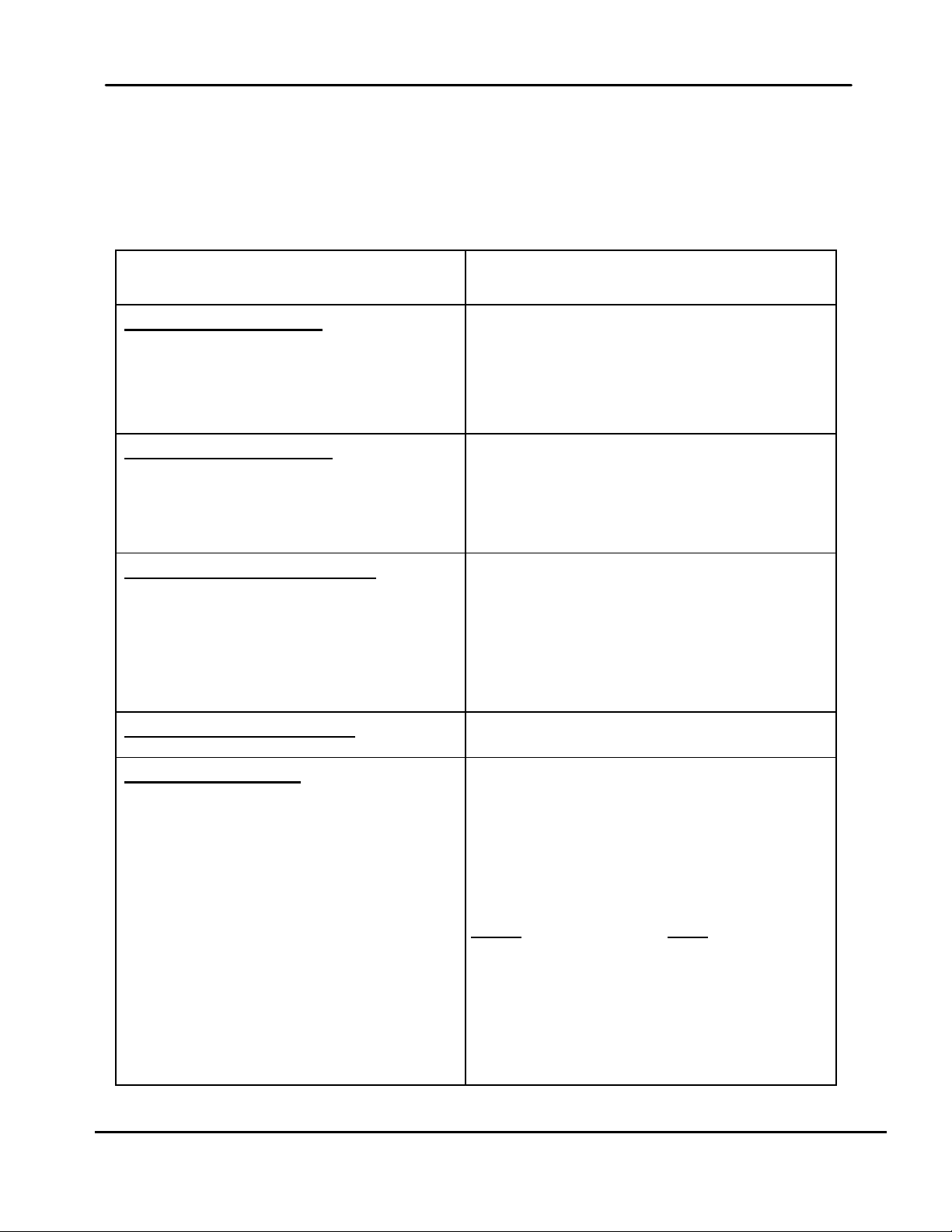
Table 1-1: Modbus Communication and Support Requirements
CHARACTERISTIC REQUIREMENT
EMS Master-To-BMS/BMS II/ACS Slave:
BMS/BMS II/ACS Master-To-C-More Slave:
EMS Master-To- C-More Slave:
RS232:
RS485:
BMS/BMS II/ACS:
C-More Controller (Slave):
Broadcast Messages:
Baud Rate:
Message Framing:
Character Framing:
Heartbeat Timeout:
RS232 (or RS485 With Optional Converter)
RS485, 2-Wire Differential Bus With Shield
RS485, 2-Wire Differential Bus With Shield
50 Feet, Maximum
4,000 Feet, Maximum
128 to 247 (From a Master EMS)
EMS)
Address
Fixed at 9600 For C-More
Adjustable For BMS/BMS II/ACS: 2400, 4800,
9600, 14.4k, 19.2k
Default = 9600
Silent period of at least 3.5 character times
Before first character and After
message
No more than 1.5 character times of silence
between received and transmitted characters
Page 8 of 200 AERCO International, Inc. • 100 Oritani Dr. • Blauvelt, NY 10913 • Ph.: 800-526-0288 05/18/12
Fixed at 10 seconds For C-More
Adjustable For BMS/BMS II/ACS: 5 to 240
Page 9

Chapter 1
Introduction & Description USER MANUAL
MODBUS
Communication GF-114
OMM-0035_0C
1.3.1 Communication Medium
The communication medium for each of the possible Modbus network configurations may vary
depending on the Master/Slave scenario being implemented. Detailed installation procedures
and wiring diagrams for the configurations described in the following paragraphs are provided in
Section 4 of this manual.
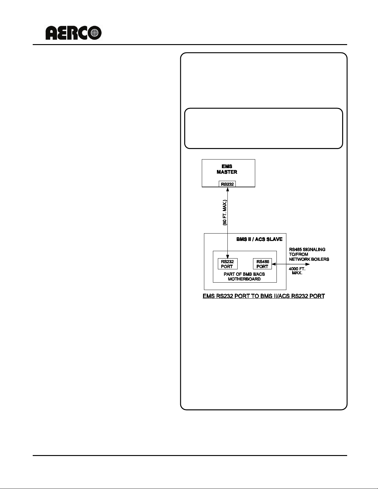
1.3.1.1 EMS Master To BMS/BMS II/ACS Slave
The Modbus network connections between the EMS and BMS/BMS II/ACS will depend on the
type of port provide on the EMS Master. If the EMS contains a RS232 port, a direct connection
can be made directly to the BMS/BMS II/ACS RS232 port. For optimum results the wire length
between the EMS and BMS/BMS II/ACS RS232 connection should not exceed 50 feet. If the
EMS Master contains a RS485 port, a RS485-to-RS232 converter will be required to implement
the Modbus network.
1.3.1.2 BMS/BMS II/ACS Master To C-More Boiler Controller Slaves
Up to a total of 32 C-More Boiler Controllers can be connected to a BMS/BMS II/ACS Master on
the Modbus Network. Multi-point drop network connections are made using shielded, twistedpair wire. In addition to the Modbus Network Boilers, up to 8 additional Legacy Boilers can be
connected to the BMS Pulse Width Modulation (PWM) wiring connection. The BMS II and ACS
do not support PWM. It should be noted that the BMS, BMS II, and ACS include a Modbus
Pass-Thru feature which, when enabled, permits an EMS to monitor and configure (but not
directly control) the boilers.
1.3.1.3 EMS Master To C-More Boiler Controller Slaves
The number of C-More Boiler Controllers which can be connected to a Modbus Network which
utilizes a third party EMS Master will depend on the EMS’s limitations. Theoretically, the
maximum number of Slave devices is limited to 127. If the EMS contains a RS232 port, a
RS232-to-RS485 converter will be required to provide the necessary RS485 interfaces and
signal levels for the C-More Boiler Controllers. Multi-drop network connections are made using
shielded, twisted-pair wire.
1.3.2 Address Support
Address support is assigned as follows:
• BMS/BMS II/ACS Address Support From EMS Master: 128 – 247 (80 – F7 hex)
• C-More Address Support From BMS/BMS II/ACS or EMS Master: 1 – 127 (01 – 7F hex)
• Broadcast Messages: Address 0 is reserved for all Broadcast messages
1.3.3 Modbus Transmission Modes
Many Modbus Controllers can be set up to transmit using either the ASCII (American Standard
Code for Information Interchange) transmission mode, or the RTU (Remote Terminal Unit)
transmission mode. However, since RTU messages can be formatted using far fewer binary
bits than the corresponding ASCII message, it is far more efficient. Therefore, all Modbus
messages for the AERCO BMS/BMS II/ACS and C-More Boiler Controllers use RTU
transmission ONLY. If a third-party EMS Master is being used in the Modbus network, ensure
that it is set for RTU transmission.
1.3.4 Timing Specifications
As Table 1-1 shows, Baud Rate and Heartbeat Timeout will vary depending on the
Configurations of the AERCO BMS/BMS II/ACS and C-More Boiler Controllers being used in the
Modbus Network. Ensure that the Baud Rate used by the controlling Master (BMS/BMS II/ACS
05/18/12 AERCO International, Inc. • 100 Oritani Dr. • Blauvelt, NY 10913 • Ph: 800-526-0288 Page 9 of 200
Page 10

GF-114
Function Code
Function Name
Read Holding Register (Read Multiple
Registers)
04
Read Input Registers
06
Preset (Write) Single Register
Diagnostics
Codes)
17
Report Slave ID
Sub-
Code
00
Return Query Data
Loop-Back
01
Restart Communications Options
Resets the Slave. Cancels Listen Only Mode.
02
Return Diagnostic Register
Not Used
04
Force Listen Only Mode
Reset by Restart Communications Option
Also cleared at power up. Clears only the
counters
12
Return Bus Communication Error Count
Slave CRC errors only.
13
Return Bus Exception Error Count
Slave Exception Response count.
Number of messages addressed to the slave
broadcast messages.
Number of messages addressed to the slave
for which no response was returned.
18
Return Bus Character Overrun Count
Number of overrun and framing errors.
OMM-0035_0C USER MANUAL Introduction & Description
MODBUS
Communication Chapter 1
or EMS) matches the appropriate Baud Rate supported by the Network Slaves (BMS/BMS
II/ACS or C-More Controllers). Also, ensure that the Modbus Master can refresh the control
information to all C-More Slaves before the Heartbeat Timeout period expires.
1.4 MODBUS FUNCTION SET SUPPORT
The complete Modbus protocol includes a total of 24 Function Codes. However, for AERCO
BMS/BMS II/ACS and C-More Boiler Controllers, only the Codes listed in Table 1-2 are
supported. The supported Diagnostic Sub-Function Codes associated with Diagnostic Function
Code 08 are listed in Table 1-3.
Table 1-2: Required Function Code Set
03
08
(See Table 1-3 for supported Sub-Function
Table 1-3: Minimum Diagnostic (Function Code 08) Sub-Function Set
Function
10 Clear Counters and Diagnostic Register
Sub-Function Name Comments
14 Return Slave Message Count
15 Return Slave No Response Count
Page 10 of 200 AERCO International, Inc. • 100 Oritani Dr. • Blauvelt, NY 10913 • Ph.: 800-526-0288 05/18/12
and successfully processed. Includes
Page 11

Chapter 1
Exception Code
Description
Comments
The function code received is not valid or
is not supported.
The data address received is invalid or is
not accessible due to security setting.
03
Illegal Data Value
The data value received is not valid
Phrase, Abbreviation
or Acronym
ACS
AERCO Control System
ASCII
American Standard Code for Information Interchange
BAS
Building Automation System
Baud
Bits per Second (bps)
BMS (BMS II)
Boiler Management System (Boiler Management System II)
(or Control Box)
used in all Benchmark and KC Series product lines
EMS
Energy Management System
FDX
Full-Duplex
HDX
Half-Duplex
Hex
Hexadecimal Number (0 - 9, A - F)
Input/Output (I/O) Box currently used on all Benchmark and KC
Series products
LSB
Least Significant Byte
A serial, half-duplex data transmission protocol developed by AEG
Modicon
MSB
Most Significant Byte
A standard for serial, full-duplex (FDX) transmission of data based
on the RS232 Standard
A standard for serial, full-duplex (FDX) transmission of data based
on the RS422 Standard
based on the RS485 Standard
RTU
Remote Terminal Unit
Introduction & Description USER MANUAL
MODBUS
Communication GF-114
OMM-0035_0C
1.5 EXCEPTION RESPONSES
With the exception of Broadcast Messages, queries transmitted by the Master expect a normal
response from the addressed Slave on the network. However, if the addressed Slave cannot
process or interpret the message, it will respond with one of the Exception Codes listed in Table
1-4.
Table 1-4: Minimum Exception Code Set
01 Illegal Function
02 Illegal Data Address
1.6 PHRASES, ABBREVIATIONS & ACRONYMS
The phrases, abbreviations and acronyms used in this manual are listed in Table 1-5.
Table 1-5: Phrases, Abbreviations and Acronyms
C-More Controller
I/O Box
Modbus®
RS232
Meaning
A control system developed by AERCO International and currently
RS422
RS485
05/18/12 AERCO International, Inc. • 100 Oritani Dr. • Blauvelt, NY 10913 • Ph: 800-526-0288 Page 11 of 200
A standard for serial, half-duplex (HDX) transmission of data
Page 12

GF-114
OMM-0035_0C USER MANUAL Introduction & Description
MODBUS
(This page intentionbally blank)
Communication Chapter 1
Page 12 of 200 AERCO International, Inc. • 100 Oritani Dr. • Blauvelt, NY 10913 • Ph.: 800-526-0288 05/18/12
Page 13

Chapter 2
Standard Register Assignments USER MANUAL
MODBUS
Communication GF-114
OMM-0035_0C
CHAPTER 2. STANDARD REGISTER ASSIGMENTS
2.1 INTRODUCTION
This Section provides the standard data register addresses assigned to the AERCO and CMore Boiler Controllers, the AERCO Boiler Management System (BMS/BMS II), and AERCO
Control System (ACS). These data registers consist of Input Registers and Holding Registers.
All register addresses provided throughout this manual are expressed as hexadecimal numbers.
2.1.1 Input Registers
The Input Registers for the AERCO C-More Boiler Controllers and AERCO BMS/BMS II/ACS
are intended for information and functions that cannot or should not be controlled remotely.
Therefore, unless otherwise specified, ALL Input Register data are READ ONLY.
IMPORTANT
All Modbus addresses specified in this manual are written
generically in decimal/hexadecimal format. However, many
Building Automation Systems utilize another form of addressing
where:
40001 is added to the generic address for a Holding Register
address.
And
30001 is added to the generic address for an Input Register
address. Be sure to check the addressing scheme being used by
the BAS that is being interfaced to the XPC Gateway.
2.1.2 Holding Registers
The Holding Registers for the AERCO C-More Boiler Controllers and AERCO BMS/BMS II/ACS
are intended for information and functions that can be read or written (R/W). Therefore unless
otherwise specified, all Holding Register data are R/W.
CAUTION
DO NOT write in any Register Addresses marked as “Reserved” in
the Input Register and Holding Register Tables which follow.
Failure to observe this precaution may result in unstable
operation.
05/18/12 AERCO International, Inc. • 100 Oritani Dr. • Blauvelt, NY 10913 • Ph: 800-526-0288 Page 13 of 200
Page 14

GF-114
Modbus Data
Decimal (Hex)
Default Message
Display Code
See Appendix A,
Table A-1 for listing
Enum (0, 1, 2, 3, 4, 5)
5 = Unit Status Fault
See Appendix A,
Conversions
See Appendix A,
Conversions
See Appendix A,
Conversions
See Appendix A,
Conversions
See Appendix A,
Conversions
See Appendix A,
Conversions
8 (0x0008)
Fire Rate Out
% (0 to 100)
9 (0x0009)
O2 Level
% (0 to 25)
10 (0x000A)
CO Level
PPM (0 to 500)
The actual range for run
0 to 999,999
12 (0x000C)
Run Cycles High (MSB)
Int (0 to 15)
OMM-0035_0C USER MANUAL Standard Register Assignments
MODBUS
Communication Chapter 2
2.2 C-MORE BOILER CONTROLLER STANDARD REGISTER ASSIGNMENTS
2.2.1 C-More Boiler Controller Standard Input Register Assignments
The Read Only Input Register addresses are listed in Table 2-1 which follows:
Table 2-1: C-More Boiler Controller Standard Input Register Address Mapping
Address
0 (0x0000)
1 (0x0001) Unit Status
2 (0x0002) Outlet Temp
3 (0x0003) Inlet Temp DEGREES_1 (0 to 1000)
4 (0x0004) Aux Temp
Menu Item Units and Range
Enum (1 to 64)
0 = Unit Status Disabled
1 = Unit Status Standby
2 = Unit Status Manual
3 = Unit Status Remote
4 = Unit Status Auto
DEGREES_1 (0 to 1000)
DEGREES_1 (0 to 1000)
Default/
Comments
Tables A-2 and A-3 for
Tables A-2 and A-3 for
Tables A-2 and A-3 for
5 (0x0005) Outdoor Temp DEGREES_2 (0 to 1000)
6(0x0006) Exhaust Temp DEGREES_2 (0 to 1000)
7 (0x0007) FFWD Temp DEGREES_1 (0 to 1000)
11 (0x000B) Run Cycles Low (LSB) int (0 to 65535)
Page 14 of 200 AERCO International, Inc. • 100 Oritani Dr. • Blauvelt, NY 10913 • Ph.: 800-526-0288 05/18/12
Tables A-2 and A-3 for
Tables A-2 and A-3 for
Tables A-2 and A-3 for
cycles is from
Page 15

Chapter 2
Modbus Data
Decimal (Hex)
The actual range for run hours
0 to 999,999
Run Hours
High (MSB)
15 (0x000F)
Flame Strength
% (0 to 100)
See Appendix A,
Conversions
17 (0x0011)
Fire Rate In
% (0 to 100)
Only applicable when in the
the front panel interface
Default = 0
communications
20 (0x0014)
Software Version
int (0 to 65535)
21 (0x0015)
22 (0x0016)
23 (0x0017)
Fault Log Code
Fault Log
The internal variable type for
and the range is 0 to 999999
Fault Log
Cycle (HIGH)
Fault Log
Date
Int (1 to 65535)
1 count/day
Fault Log
Time
Int (0 to 1439)
1 count/min.
See Appendix A,
Conversions
Standard Register Assignments USER MANUAL
MODBUS
Communication GF-114
OMM-0035_0C
Table 2-1: C-More Boiler Controller Standard Input Register Address Mapping
(Continued)
Address
13 (0x000D)
14 (0x000E)
16 (0x0010) Active Set point DEGREES_1 (0 to 1000)
18 (0x0012) Manual Fire Rate % (0 to 100)
19 (0x0013)
Menu Item Units and Range
Run Hours
Low (LSB)
Comm Address
int (0 to 65535)
int (0 to 15)
Int (0 to 127)
Default/
Comments
is from
Tables A-2 and A-3 for
Manual Mode and controlled by
Comm Address 0 disables the
Controller’s Modbus
24 (0x0018)
25 (0x0019)
26 (0x001A)
27 (0x001B)
28 (0x001C)
(Reserved)
Fault Log
Cycle (LOW)
Sensor Log
Active Setpoint
int (0 to 65535)
Int (0 to 15)
DEGREES_1 (0 to 1000)
fault log display cycle is long
Tables A-2 and A-3 for
05/18/12 AERCO International, Inc. • 100 Oritani Dr. • Blauvelt, NY 10913 • Ph: 800-526-0288 Page 15 of 200
Page 16

GF-114
Modbus Data
Decimal (Hex)
See Appendix A,
Conversions
See Appendix A,
Conversions
See Appendix A,
Conversions
See Appendix A,
Conversions
See Appendix A,
Conversions
See Appendix A,
Conversions
Sensor Log
CO xmitter
Sensor Log
O2 xmitter
Sensor Log
Flow Meter
73 (“I”) = Ignition
82 (“R”) = Run
Time Log
Fire Rate
Time Log
Flame Strength
Time Log
Run Length
Time Log
Date
Int (0 to 65535)
1 count/day
Time Log
Time
Int (0 to 1439)
1 count/min.
OMM-0035_0C USER MANUAL Standard Register Assignments
MODBUS
Communication Chapter 2
Table 2-1: C-More Boiler Controller Standard Input Register Address Mapping
(Continued)
Address
29 (0x001D)
30 (0x001E)
31 (0x001F)
32 (0x0020)
33 (0x0021)
34 (0x0022)
Menu Item Units and Range
Sensor Log
Outlet Temp
Sensor Log
Inlet Temp
Sensor Log
FFWD Temp
Sensor Log
Exhaust Temp
Sensor Log
Outdoor Temp
Sensor Log
Aux Temp
DEGREES_1 (0 to 1000)
DEGREES_1 (0 to 1000)
DEGREES_1 (0 to 1000)
DEGREES_3 (0 to 1000)
DEGREES_2 (0 to 1000)
DEGREES_1 (0 to 1000)
Default/
Comments
Tables A-2 and A-3 for
Tables A-2 and A-3 for
Tables A-2 and A-3 for
Tables A-2 and A-3 for
Tables A-2 and A-3 for
Tables A-2 and A-3 for
35 (0x0023)
36 (0x0024)
37 (0x0025)
38 (0x0026)
39 (0x0027)
40 (0x0028)
41 (0x0029)
42 (0x002A)
43 (0x002B)
Time Log
Status
PPM_UNITS
% (0 to 100)
GPM_UNITS
74 (“O”) = Off
80 (“P”) = Power Up
% (0 to 100)
% (0 to 100)
Int (0 to 65535)
Page 16 of 200 AERCO International, Inc. • 100 Oritani Dr. • Blauvelt, NY 10913 • Ph.: 800-526-0288 05/18/12
Page 17

Chapter 2
Modbus Data
Decimal (Hex)
See Appendix A,
Remote Set Point Mode
Normally Read Only. R/W
ONLY in Direct Drive Mode.
2 (0x0002)
Modbus Password
int (0 to 65535)
Default = 0
3 (0x0003)
Password
int (0 to 65535)
Default = 0
See Appendix A,
Default = 130°F
5 (0x0005)
(Reserved)
Int (0 to 1439)
1count/min
Date count starts with Jan.
counts
bool (0, 1)
1=Degrees Celsius (°C)
enum (0, 1, 2, 3, 4)
3 = 19.2k
bool (0, 1)
1 = Water Heater
enum (0, 1, 2, 3, 4, 5)
5 = 3 MBTU
Standard Register Assignments USER MANUAL
MODBUS
Communication GF-114
OMM-0035_0C
2.2.2 C-More Boiler Controller Standard Holding Register Assignments
The Read/Write Input Register address assignments are listed in Table 2-2 which follows.
Unless otherwise specified, all Holding Register menu items are Read/Write (R/W)
Table 2-2: C-More Controller Standard Holding Register Address Mapping
Address
0 (0x0000)
1 (0x0001) Net Direct Drive % (0 to 100)
4 (0x0004) Internal Set Point DEGREES_1 (0 to 1000)
6 (0x0006) Time
7 (0x0007) Date
Menu Item Units and Range Comments
Net Remote Set
Point
DEGREES_1 (0 to 1000)
int (0 to 65535)
1count/day
Tables A-2 and A-3 for
Conversions. R/W ONLY in
Tables A-2 and A-3 for
Conversions
1, 2000. For Example: Jan.
1 2001 would equal 365
8 (0x0008) Unit of Temp
9 (0x0009) Baud Rate
10 (0x000A) Unit Type
11 (0x000B) Unit Size
05/18/12 AERCO International, Inc. • 100 Oritani Dr. • Blauvelt, NY 10913 • Ph: 800-526-0288 Page 17 of 200
0= Degrees Fahrenheit (°F)
0 = 2.4k
1 = 4.8k
2 = 9.6k
0 = Boiler
0 = 0.5 MBTU
1 = 1 MBTU
2 = 1.5 MBTU
3 = 2 MBTU
4 = 2.5 MBTU
Default = °F
For C-More RS232 port
ONLY
Default = 2 (9.6k)
Default = Boiler
Default = 1 (1 MBTU)
Page 18

GF-114
Modbus Data
Decimal (Hex)
enum (0, 1, 2, 3, 4):
4 = Outdoor Reset
enum (0, 1, 2, 3):
3 = Network
See Appendix A,
Conversions
Int (1 to 99 counts)
(Counts = Actual x 10)
Actual Default = 1.2
1.2 x 10 = 12 counts
bool (0,1)
1 = True
See Appendix A,
Default = 60°F
See Appendix A,
Default = 60°F
See Appendix A,
Default = 200°F
See Appendix A,
Default = 210°F
21 (0x0015)
Max Fire Rate
% (40 - 100)
Default = 100%
MIN_UNITS (0 to 30)
1count/min
SEC_UNITS (0 to 120)
1count/sec
OMM-0035_0C USER MANUAL Standard Register Assignments
MODBUS
Communication Chapter 2
Table 2-2: C-More Controller Standard Holding Register Address Mapping
(Continued)
Address
12 (0x000C) Boiler Mode
13 (0x000D) Remote Signal
14 (0x000E) Bldg Ref Temp DEGREES_1 (0 to 1000)
15 (0x000F) Reset Ratio
16 (0x0010)
Menu Item Units and Range Comments
0 = Constant Setpt
1 = Remote Setpt
2 = Direct Drive
3 = Combo Unit
0 = 4 - 20 mA /1 - 5V
1 = 0 -20mA/0 - 5V
2 = PWM Input
Actual Range = 0.1 to 9.9
Outdoor Sensor
Enable
0 = False
Default = 0
(Constant Setpt)
Default = 0
(4 - 20 mA/1 - 5V)
Tables A-2 and A-3 for
Therefore:
Default = 0 (False)
17 (0x0011) System Start Temp
18 (0x0012) Set Point Lo Limit DEGREES_1 (0 to 1000)
19 (0x0013) Set Point Hi Limit DEGREES_1 (0 to 1000)
20 (0x0014) Temp Hi Limit
22 (0x0016) Pump Delay Timer
23 (0x0017) Aux Start On Delay
Page 18 of 200 AERCO International, Inc. • 100 Oritani Dr. • Blauvelt, NY 10913 • Ph.: 800-526-0288 05/18/12
DEGREES_2 (0 to 1000)
DEGREES_1 (0 to 1000)
Tables A-2 and A-3 for
Conversions
Tables A-2 and A-3 for
Conversions
Tables A-2 and A-3 for
Conversions
Tables A-2 and A-3 for
Conversions
Default = 0 min.
Default = 0 sec.
Page 19

Chapter 2
Modbus Data
Decimal (Hex)
enum (0, 1)
1=Constant Setpoint
SEC_UNITS (2 to 60)
1count/sec
See Appendix A,
Conversions
27 (0x001B)
0.00 to 2.00
Actual x 100 Counts
Heater:1.60 (160 counts)
28 (0x001C)
Actual x 100 Counts
(10 counts)
29
Water Heater ONLY
Conversions
30 (0x001E)
Water Heater ONLY
Conversions
31 (0x001F)
bool (0, 1)
1 = On
32 (0x0020)
Thru
59 (0x003B)
60 (0x003C)
bool (0, 1)
1 = Enabled
61 (0x003D)
See Appendix A,
Conversions
62 (0x003E)
Thru
66 (0x0042)
MODBUS
Communication GF-114
Standard Register Assignments USER MANUAL
Table 2-2: C-More Controller Standard Holding Register Address Mapping
(Continued)
OMM-0035_0C
Address
24 (0x0018) Failsafe Mode
25 (0x0019) Low Fire Timer
26 (0x001A) Prop Band
Integral Gain
(0x001D) Min Load Adjust
Menu Item Units and Range Comments
Derivative Time
0=Shutdown
ABS_DEG_1 (0 to 1000)
(0.01 increments)
MIN_UNITS (0.00 to 2.00)
(0.01 min. increments)
1count/0.01min
ABS_DEG_1 (0 to 1000)
Default = 0 (Shutdown)
Default = 2 sec.
Tables A-2 and A-3 for
Defaults:
Boiler: 0.10 (10 counts),
Defaults:
Boiler: 0.00 min.
(0 counts)
Heater: 0.10 min
See Appendix A,
Tables A-2 and A-3 for
05/18/12 AERCO International, Inc. • 100 Oritani Dr. • Blauvelt, NY 10913 • Ph: 800-526-0288 Page 19 of 200
Max Load Adjust
Outlet Feedback
(Reserved)
Set Point Limit Band
Set Point Limiting
(Reserved)
ABS_DEG_1 (0 to 1000)
0 = Off
0 = Disabled
ABS_DEG_1 (0 to 1000)
See Appendix A,
Tables A-2 and A-3 for
Default = 1 (On)
Water Heater ONLY
Default = 0 (Disabled)
Tables A-2 and A-3 for
Page 20

GF-114
Modbus Data
Decimal (Hex)
67 (0x0043)
Enum (0 to 8)
8 = 24 Hrs.
68 (0x0044)
Fault Log Pointer
int 0 - 9
69 (0x0045)
Sensor Log Pointer
int 0 - 1199
70 (0x0046)
Time Log Pointer
int 0 - 10239
71 (0x0047)
65535 (0xFFFF)
OMM-0035_0C USER MANUAL Standard Register Assignments
MODBUS
Communication Chapter 2
Table 2-2: C-More Controller Standard Holding Register Address Mapping
(Continued)
Thru
Address
Sensor Log Interval
Menu Item Units and Range Comments
0 = Off
1 = 1 Min.
2 = 5 Min.
3 = 15 Min.
4 = 30 Min.
5 = 1 Hr.
6 = 6 Hrs
7 = 12 Hrs.
(Reserved)
Default = 4 (30 min)
Available for future
expansion.
Page 20 of 200 AERCO International, Inc. • 100 Oritani Dr. • Blauvelt, NY 10913 • Ph.: 800-526-0288 05/18/12
Page 21

Chapter 2
Modbus Data
Decimal (Hex)
0 (0x0000)
(Reserved)
1 (0x0001)
Header Temperature
40 to 220°F
Outside Air
Temperature
Indoor Air/Return
Temperature
Indoor Air Temp = BMS
Return Temp = BMS II
0 to 100%
(out to boilers)
Header Set
Temperature
Default = 128
is Off-Line as a Slave)
0 to 40 (for BMS)
0 to 32 (for BMS II)
0 to 40 (for BMS)
0 to 32 (for BMS II)
9 (0x0009)
(Reserved)
0 to 65535
5 = 4-20mA Input Error
11 (0x000B)
15 (0x000F)
1 to 40 (for BMS)
1 to 32 (for BMS II)
Standard Register Assignments USER MANUAL
MODBUS
Communication GF-114
OMM-0035_0C
2.3 BMS/BMS II CONTROLLER STANDARD REGISTER ASSIGNMENTS
2.3.1 BMS/BMS II Controller Standard Input Register Assignments
The Read Only Input Register address assignments for the BMS/BMS II are listed in Table 2-3
which follows:
Table 2-3: BMS/BMS II Standard Input Register Address Mapping
Address
2 0x0002)
3 (0x0003)
4 (0x0004) Fire Rate Out
5 (0x0005)
6 (0x0006) Network Address
7 (0x0007) Total Boilers Fired
8 (0x0008) Total Boilers On Line
Menu Item Units and Range
-60 to 120°F
40 to 220°F
40 to 220°F
128 to 247
Default/
Comments
(If Address = 0, BMS/ BMS II
10 (0x000A)
thru
16 (0x0010) Lead Boiler Number
05/18/12 AERCO International, Inc. • 100 Oritani Dr. • Blauvelt, NY 10913 • Ph: 800-526-0288 Page 21 of 200
Bit:
0 = Outside Air Sensor
Fault/Message Code
(Reserved)
1 = Header Sensor Error
2 = Interlock 1 Error
3 = Interlock 2 Error
4 = Indoor Air Sensor Error/
Return Sensor Error
Interpret Bit 4 as follows:
Indoor Air Sensor Error
applies to BMS.
Return Sensor Error applies
to BMS II.
Page 22

GF-114
Dec. (Hex)
119 = Not On-Line
1–40 = Fired & Sequence
Boilers 1 - 8 are
referred to as the
Legacy (PWM)
Boilers.(BMS Only)
Boiler 2 Status
(PWM Boiler 2)
(Same As Above)
(BMS Only)
Boiler 3 Status
(PWM Boiler 3)
(Same As Above)
(BMS Only)
Boiler 4 Status
(PWM Boiler 4)
(Same As Above)
(BMS Only)
Boiler 5 Status
(PWM Boiler 5)
(Same As Above)
(BMS Only)
Boiler 6 Status
(PWM Boiler 6)
(Same As Above)
(BMS Only)
Boiler 7 Status
(PWM Boiler 7)
(Same As Above)
(BMS Only)
Boiler 8 Status
(PWM Boiler 8)
(Same As Above)
(BMS Only)
119 = Not On-Line
Faulted
Boiler 10 Status (BMS) (Net Boiler 2)
Boiler 2 Status (BMS II)
Boiler 11 Status (BMS) (Net Boiler 3)
Boiler 3 Status (BMS II)
Boiler 12 Status (BMS) (Net Boiler 4)
Boiler 4 Status (BMS II)
Boiler 13 Status (BMS) (Net Boiler 5)
Boiler 5 Status (BMS II)
Boiler 14 Status (BMS) (Net Boiler 6)
Boiler 6 Status (BMS II)
Boiler 15 Status (BMS) (Net Boiler 7)
Boiler 7 Status (BMS II)
Boiler 16 Status (BMS) (Net Boiler 8)
Boiler 8 Status (BMS II)
OMM-0035_0C USER MANUAL Standard Register Assignments
MODBUS
Communication Chapter 2
Table 2-3: BMS/BMS II Standard Input Register Address Mapping (Continued)
Modbus Data
Address
Menu Item Units and Range Comments
17 (0x0011)
18 (0x0012)
19 (0x0013)
20 (0x0014)
21 (0x0015)
22 (0x0016)
23 (0x0017)
24 (0x0018)
25 (0x0019)
Boiler 1 Status
(PWM Boiler 1)
Boiler 9 Status (BMS)
(Net Boiler 1)
Boiler 1 Status (BMS II)
120 = On-Line But Not
Fired
(Same As Above)
(Same As Above)
(Same As Above)
(Same As Above)
(Same As Above)
(Same As Above)
(Same As Above)
120 = On-Line But Not
Fired
1–40 = Fired & Sequence
121 = On-Line But
Disabled
122 = On-Line But
Boilers 9 - 32 are the
Network Boilers.
BMS II has only
Network Boilers,
therefore Net Boiler 1
= Boiler 1, etc.
26 (0x001A)
27 (0x001B)
28 (0x001C)
29 (0x001D)
30 (0x001E)
31 (0x001F)
32 (0x0020)
Page 22 of 200 AERCO International, Inc. • 100 Oritani Dr. • Blauvelt, NY 10913 • Ph.: 800-526-0288 05/18/12
Same As Above
Same As Above
Same As Above
Same As Above
Same As Above
Same As Above
Same As Above
Page 23

Chapter 2
Decimal (Hex)
(Net Boiler 9)
119 = Not On-Line
122 = On-Line But Faulted
Boiler 18 Status (BMS) (Net Boiler
Boiler 10 Status (BMS II)
Boiler 19 Status (BMS) (Net Boiler
Boiler 11 Status (BMS II)
Boiler 20 Status (Net Boiler 12)
Boiler 12 Status (BMS II)
Boiler 21 Status (Net Boiler 13)
Boiler 13 Status (BMS II)
Boiler 22 Status (Net Boiler 14)
Boiler 14 Status (BMS II)
Boiler 23 Status (Net Boiler 15)
Boiler 15 Status (BMS II)
Boiler 24 Status (Net Boiler 16)
Boiler 16 Status (BMS II)
Boiler 25 Status (Net Boiler 17)
Boiler 17 Status (BMS II)
Boiler 26 Status Net Boiler 18)
Boiler 18 Status (BMS II)
Boiler 27 Status (Net Boiler 19)
Boiler 19 Status (BMS II)
Boiler 28 Status (Net Boiler 20)
Boiler 20 Status (BMS II)
Boiler 29 Status (Net Boiler 21)
Boiler 21 Status (BMS II)
Boiler 30 Status (Net Boiler 22)
Boiler 22 Status (BMS II)
Standard Register Assignments USER MANUAL
MODBUS
Communication GF-114
OMM-0035_0C
Table 2-3: BMS/BMS II Standard Input Register Address Mapping (Continued)
Modbus Data
Address
Menu Item Units and Range Comments
33 (0x0021)
34 (0x0022)
35 (0x0023)
36 (0x0024)
37 (0x0025)
38 (0x0026)
39 (0x0027)
40 (0x0028)
Boiler 17 Status (BMS)
Boiler 9 Status (BMS II)
10)
11)
120 = On-Line But Not Fired
1–40 = Fired & Sequence
121 = On-Line But Disabled
Same As Above
Same As Above
Same As Above
Same As Above
Same As Above
Same As Above
Same As Above
41 (0x0029)
42 (0x002A)
43 (0x002B)
44 (0x002C)
45 (0x002D)
46 (0x002E)
05/18/12 AERCO International, Inc. • 100 Oritani Dr. • Blauvelt, NY 10913 • Ph: 800-526-0288 Page 23 of 200
Same As Above
Same As Above
Same As Above
Same As Above
Same As Above
Same As Above
Page 24

GF-114
Decimal (Hex)
119 = Not On-Line
Faulted
Boiler 32 Status (Net Boiler 24)
Boiler 24 Status (BMS II)
Boiler 33 Status (Net Boiler 25)
Boiler 25 Status (BMS II)
Boiler 34 Status (Net Boiler 26)
Boiler 26 Status (BMS II)
Boiler 35 Status (Net Boiler 27)
Boiler 27 Status (BMS II)
Boiler 36 Status (Net Boiler 28)
Boiler 28 Status (BMS II)
Boiler 37 Status (Net Boiler 29)
Boiler 29 Status (BMS II)
Boiler 38 Status (Net Boiler 30)
Boiler 30 Status (BMS II)
Boiler 39 Status (Net Boiler 31)
Boiler 31 Status (BMS II)
Boiler 40 Status (Net Boiler 32)
Boiler 32 Status (BMS II)
Bit map of Input/Output
Bit 7 = Empty
58 (0x003A)
Return Sensor Temp
40 °F to 220°F
BMS II Only
OMM-0035_0C USER MANUAL Standard Register Assignments
MODBUS
Communication Chapter 2
Table 2-3: BMS/BMS II Standard Input Register Address Mapping (Continued)
Modbus Data
Address
47 (0x002F)
Boiler 31 Status (Net Boiler 23)
Boiler 23 Status (BMS II)
Menu Item Units and Range Comments
120 = On-Line But Not
Fired
1–40 = Fired & Sequence
121 = On-Line But
Disabled
122 = On-Line But
48 (0x0030)
49 (0x0031)
50 (0x0032)
51 (0x0033)
52 (0x0034)
53 (0x0035)
54 (0x0036)
55 (0x0037)
56 (0x0038)
57 (0x0039) I/O Status 0 to 255
Same As Above
Same As Above
Same As Above
Same As Above
Same As Above
Same As Above
Same As Above
Same As Above
status (BMS II Only)
Bit 0 = AUX Relay
Bit 1 = Fault Relay
Bit 2 = Sys Start Relay
Bit 3 = Empty
Bit 4 = Setback
Bit 5 = Interlock 2
Bit 6 = Interlock 1
Page 24 of 200 AERCO International, Inc. • 100 Oritani Dr. • Blauvelt, NY 10913 • Ph.: 800-526-0288 05/18/12
Page 25

Chapter 2
Decimal (Hex)
59 (0x003B)
Net Blr 1 Outlet Temp
40°F to 220°F
When Blr Cntl Type = 1 or 2
60 (0x003C)
Net Blr 2 Outlet Temp
40°F to 220°F
61 (0x003D)
Net Blr 3 Outlet Temp
40°F to 220°F
62 (0x003E)
Net Blr 4 Outlet Temp
40°F to 220°F
63 (0x003F)
Net Blr 5 Outlet Temp
40°F to 220°F
64 (0x0040)
Net Blr 6 Outlet Temp
40°F to 220°F
65 (0x0041)
Net Blr 7 Outlet Temp
40°F to 220°F
66 (0x0042)
Net Blr 8 Outlet Temp
40°F to 220°F
67 (0x0043)
Net Blr 9 Outlet Temp
40°F to 220°F
68 (0x0044)
Net Blr 10 Outlet Temp
40°F to 220°F
69 (0x0045)
Net Blr 11 Outlet Temp
40°F to 220°F
70 (0x0046)
Net Blr 12 Outlet Temp
40°F to 220°F
71 (0x0047)
Net Blr 13 Outlet Temp
40°F to 220°F
72 (0x0048)
Net Blr 14 Outlet Temp
40°F to 220°F
73 (0x0049)
Net Blr 15 Outlet Temp
40°F to 220°F
74 (0x004A)
Net Blr 16 Outlet Temp
40°F to 220°F
75 (0x004B)
Net Blr 17 Outlet Temp
40°F to 220°F
76 (0x004C)
Net Blr 18 Outlet Temp
40°F to 220°F
77 (0x004D)
Net Blr 19 Outlet Temp
40°F to 220°F
78 (0x004E)
Net Blr 20 Outlet Temp
40°F to 220°F
79 (0x004F)
Net Blr 21 Outlet Temp
40°F to 220°F
80 (0x0050)
Net Blr 22 Outlet Temp
40°F to 220°F
81 (0x0051)
Net Blr 23 Outlet Temp
40°F to 220°F
82 (0x0052)
Net Blr 24 Outlet Temp
40°F to 220°F
83 (0x0053)
Net Blr 25 Outlet Temp
40°F to 220°F
84 (0x0054)
Net Blr 26 Outlet Temp
40°F to 220°F
85 (0x0055)
Net Blr 27 Outlet Temp
40°F to 220°F
Standard Register Assignments USER MANUAL
MODBUS
Communication GF-114
OMM-0035_0C
Table 2-3: BMS/BMS II Standard Input Register Address Mapping (Continued)
Modbus Data
Address
Menu Item
Units and
Comments
Range
05/18/12 AERCO International, Inc. • 100 Oritani Dr. • Blauvelt, NY 10913 • Ph: 800-526-0288 Page 25 of 200
Page 26

GF-114
Decimal (Hex)
86 (0x0056)
Net Blr 28 Outlet Temp
40°F to 220°F
87 (0x0057)
Net Blr 29 Outlet Temp
40°F to 220°F
88 (0x0058)
Net Blr 30 Outlet Temp
40°F to 220°F
89 (0x0059)
Net Blr 31 Outlet Temp
40°F to 220°F
90 (0x005A)
Net Blr 32 Outlet Temp
40°F to 220°F
0 to 64 for Cmore;
0 to 65535 for MLX (BCM)
93 (0x005D)
Net Blr 2 Code
Same as Above
94 (0x005E)
Net Blr 3 Code
Same as Above
95 (0x005F)
Net Blr 4 Code
Same as Above
96 (0x0060)
Net Blr 5 Code
Same as Above
97 (0x0061)
Net Blr 6 Code
Same as Above
98 (0x0062)
Net Blr 7 Code
Same as Above
99 (0x0063)
Net Blr 8 Code
Same as Above
100 (0x0064)
Net Blr 9 Code
Same as Above
101 (0x0065)
Net Blr 10 Code
Same as Above
102 (0x0066)
Net Blr 11 Code
Same as Above
103 (0x0067)
Net Blr 12 Code
Same as Above
104 (0x0068)
Net Blr 13 Code
Same as Above
105 (0x0069)
Net Blr 14 Code
Same as Above
106 (0x006A)
Net Blr 15 Code
Same as Above
107 (0x006B)
Net Blr 16 Code
Same as Above
108 (0x006C)
Net Blr 17 Code
Same as Above
109 (0x006D)
Net Blr 18 Code
Same as Above
110 (0x006E)
Net Blr 19 Code
Same as Above
111 (0x006F)
Net Blr 20 Code
Same as Above
112 (0x0070)
Net Blr 21 Code
Same as Above
OMM-0035_0C USER MANUAL Standard Register Assignments
MODBUS
Communication Chapter 2
Table 2-3: BMS/BMS II Standard Input Register Address Mapping (Continued)
Modbus Data
Address
92 (0x005C) Net Blr 1 Code
Menu Item
Units and
Comments
Range
Page 26 of 200 AERCO International, Inc. • 100 Oritani Dr. • Blauvelt, NY 10913 • Ph.: 800-526-0288 05/18/12
Page 27

Chapter 2
Decimal (Hex)
0 to 64 for Cmore;
0 to 65535 for MLX (BCM)
113 (0x0071)
Net Blr 22 Code
Same as Above
114 (0x0072)
Net Blr 23 Code
Same as Above
115 (0x0073)
Net Blr 24 Code
Same as Above
116 (0x0074)
Net Blr 25 Code
Same as Above
117 (0x0075)
Net Blr 26 Code
Same as Above
118 (0x0076)
Net Blr 27 Code
Same as Above
119 (0x0077)
Net Blr 28 Code
Same as Above
120 (0x0078)
Net Blr 29 Code
Same as Above
121 (0x0079)
Net Blr 30 Code
Same as Above
122 (0x007A)
Net Blr 31 Code
Same as Above
123 (0x007B)
Net Blr 32 Code
Same as Above
124 (0x007C)
Standard Register Assignments USER MANUAL
MODBUS
Communication GF-114
OMM-0035_0C
Table 2-3: BMS/BMS II Standard Input Register Address Mapping (Continued)
Modbus Data
Address
Menu Item Units and Range Comments
112 (0x0070) Net Blr 21 Code
Thru
65535 (0xFFFF)
05/18/12 AERCO International, Inc. • 100 Oritani Dr. • Blauvelt, NY 10913 • Ph: 800-526-0288 Page 27 of 200
(Reserved for future
expansion)
Page 28

GF-114
Modbus Data
Decimal (Hex)
0 (0x0000)
(Reserved)
1 (0x0001)
(Reserved)
2 (0x0002)
(Reserved)
3 (0x0003)
(Reserved)
Valid when Header Set Mode =
Signal = Network
5 (0x0005)
System Start Temp
32 to 120°F
Default = 70°F
0 or 1, 0 = Temp Only,
1 = Temp and Load
Manual Hdr Set
Temp/Internal Setpt
8 (0x0008)
Bldg Ref Temp
40 to 220°F
Default = 70°F
0.0 to 20.0°F/°F
(0.5°F/°F increments)
Default = 00.0°F/°F
(Value x 10) (BMS Only)
Indoor Setpoint
Temp
Default = 70°F
(BMS Only)
0.3 to 3.0
(0.1 increments),
Default = 1.2
(Value x 10)
12 (0x000C)
Max Header Temp
40 to 220°F
Default = 220°F
13 (0x000D)
Min Header Temp
40 to 220°F
Default = 40°F
Default = 45% (BMS)
Default = 20% (BMS II)
Default = 18% (BMS)
Default = 16% (BMS II)
0.00 to 9.99 Rep/Min
(in 0.01 increments
Default = 0.15 Rep/Min
(Value x 100)
0, 1, or 2
2 = Remote Setpt
OMM-0035_0C USER MANUAL Standard Register Assignments
MODBUS
Communication Chapter 2
2.3.2 BMS/BMS II Controller Standard Holding Register Assignments
The Holding Register address assignments for the BMS/BMS II/ACS are listed in Table 2-4
which follows. Unless otherwise specified, all Holding Register Menu items are Read/Write
(R/W).
Table 2-4: BMS/BMS II Standard Holding Register Address Mapping
Address
4 (0x0004)
6 (0x0006) System Start Option
7 (0x0007)
9 (0x0009) Indoor Prop Band
Menu Item Units and Range
Net Header Set
Temp
Default/
Comments
40 to 220°F
40 to 220°F Default = 160°F
Remote Setpt and Remote
Default = 0
10 (0x000A)
11 (0x000B) Reset Ratio
14 (0x000E) Start Percent 25 to 100%
15 (0x000F) Stop Percent 10 to 45%
16 (0x0010) Integral Gain
17 (0x0011) Header Set Mode
Page 28 of 200 AERCO International, Inc. • 100 Oritani Dr. • Blauvelt, NY 10913 • Ph.: 800-526-0288 05/18/12
50 to 150°F
0 = Constant Setpt
1 = In/Outdoor Reset
Default = 0
(Constant Setpt))
Page 29

Chapter 2
Decimal (Hex)
-2.00 to 2.00
19 0x0013)
Header Temp Bandwidth
5 to 120°F
Default = 70°F
20 (0x0014)
Aux Relay Open
0 to 99%
Default = 45%
0 or 1
1 = 100% Fire Rate and Off
0 or 1
Setpt
0, 1, 2, 3
3 = Interlock 2
0 or 1
1 = Manual
0, 1 or 2
2 = Combination
Default = 0 (BMS Only)
assign Combo Boilers)
27 (0x001B)
(Reserved)
28 (0x001C)
(Reserved)
29 (0x001D)
(Reserved)
Max Power Input
Default = 100%
(Fire Rate)
Interlock 1 Method
(BMS II)
0 or 1
1 = Start Enabled
MODBUS
Communication GF-114
Standard Register Assignments USER MANUAL
Table 2-4: BMS/BMS II Standard Holding Register Address Mapping (Cont.)
OMM-0035_0C
Modbus Data
Address
18 (0x0012) Derivative Gain
21 (0x0015) Aux Relay Mode
22 (0x0016)
23 (0x0017)
Menu Item Units and Range
Temp Sensor Fail
Mode/Failsafe Mode
Fault Alarm Relay Mode
(0.00 increments)
0 = 100% Fire Rate
0 = Shutdown
1 = Switch Inputs/Constant
0 = All Faults,
1 = No Interlock
2 = Interlock 1
Default/
Comments
Default = 0.15
(Value x 100)
Default = 1
(100% Fire Rate & Off)
Default = 0
(Shutdown)
Default = 0
(All Faults)
24 (0x0018) Fault Alarm Clear Method
25 (0x0019) Boiler Operation Mode
Number Of
26 (0x001A)
30 (0x001E)
31 (0x001F)
Combination Mode
Boilers
(BMS)/Sys Intlk Config
0 = Automatic
0 = Parallel
1 = Sequential
0 to 4
50 to 100%
0 = Always Enabled
Default = 0
(Automatic)
Default = 1
(Sequential)
(Start at Boiler 8 and
work back to Boiler 5 to
Default = 1
(Start Enabled)
05/18/12 AERCO International, Inc. • 100 Oritani Dr. • Blauvelt, NY 10913 • Ph: 800-526-0288 Page 29 of 200
Page 30

GF-114
Decimal (Hex)
32 (0x0020)
Real Time Clock Minutes
00 to 59 Minutes
Present Time
Real Time Clock
Hours
Real Time Clock
Day of Week
Real Time Clock
Year
Real Time Clock
Day of Month
Real Time Clock
Month
38 (0x0026)
Offset Temp Day 1
-50 to 50°F
Default = 0°F
39 (0x0027)
Offset Temp Day 2
-50 to 50°F
Default = 0°F
40 (0x0028)
Offset Temp Day 3
-50 to 50°F
Default = 0°F
41 (0x0029)
Offset Temp Day 4
-50 to 50°F
Default = 0°F
42 (0x002A)
Offset Temp Day 5
-50 to 50°F
Default = 0°F
43 (0x002B)
Offset Temp Day 6
-50 to 50°F
Default = 0°F
44 (0x002C)
Offset Temp Day 7
-50 to 50°F
Default = 0°F
Offset On Time
Day 1 – Minutes
Offset On Time
Day 2 – Minutes
Offset On Time
Day 3 – Minutes
Offset On Time
Day 4 – Minutes
Offset On Time
Day 5 – Minutes
Offset On Time
Day 6 – Minutes
Offset On Time
Day 7 – Minutes
OMM-0035_0C USER MANUAL Standard Register Assignments
MODBUS
Communication Chapter 2
Table 2-4: BMS/BMS II Standard Holding Register Address Mapping (Cont.)
Modbus Data
Address
33 (0x0021)
34 (0x0022)
35 (0x0023)
36 (0x0024)
37 (0x0025)
Menu Item
Units and
Range
00 to 23 Hours Present Time
1 to 7 Present Day
00 to 99 Present Year
01 to 31 Present Day of Month
01 to 12 Present Month
Default/
Comments
45 (0x002D)
46 (0x002E)
47 (0x002F)
48 (0x0030)
49 (0x0031)
50 (0x0032)
51 (0x0033)
00 to 59 Minutes Default = 0
00 to 59 Minutes Default = 0
00 to 59 Minutes Default = 0
00 to 59 Minutes Default = 0
00 to 59 Minutes Default = 0
00 to 59 Minutes Default = 0
00 to 59 Minutes Default = 0
Page 30 of 200 AERCO International, Inc. • 100 Oritani Dr. • Blauvelt, NY 10913 • Ph.: 800-526-0288 05/18/12
Page 31

Chapter 2
Decimal (Hex)
52 (0x0034)
Offset On Time
Day 1 – Hours
00 to 23 Hours
Default = 0
53 (0x0035)
Offset On Time
Day 2 – Hours
00 to 23 Hours
Default = 0
54 (0x0036)
Offset On Time
Day 3 – Hours
00 to 23 Hours
Default = 0
55 (0x0037)
Offset On Time
Day 4 – Hours
00 to 23 Hours
Default = 0
56 (0x0038)
Offset On Time
Day 5 – Hours
00 to 23 Hours
Default = 0
57 (0x0039)
Offset On Time
Day 6 – Hours
00 to 23 Hours
Default = 0
58 (0x003A)
Offset On Time
Day 7 – Hours
00 to 23 Hours
Default = 0
59 (0x003B)
Offset Enable
0 or 1
1 = Enabled
Default = 0
60 (0x003C)
Header Offset
0 to 5°F
Default = 0°F
61 (0x003D)
System Start Interlock
1, 2 or 3
Opens Start
3 = Intlk 2 Open Start Relay
Default = 2
62 (0x003E)
69 (0x0045)
(Reserved)
70 (0x0046)
Offset Off Time
Day 1 – Minutes
0 to 59 Minutes
Default = 0
71 (0x0047)
Offset Off Time
Day 2 – Minutes
0 to 59 Minutes
Default = 0
72 (0x0048)
Offset Off Time
Day 3– Minutes
0 to 59 Minutes
Default = 0
73 (0x0049)
Offset Off Time
Day 4– Minutes
0 to 59 Minutes
Default = 0
74 (0x004A)
Offset Off Time
Day 5 – Minutes
0 to 59 Minutes
Default = 0
75 (0x004B)
Offset Off Time
Day 6 – Minutes
0 to 59 Minutes
Default = 0
MODBUS
Communication GF-114
Standard Register Assignments USER MANUAL
Table 2-4: BMS/BMS II Standard Holding Register Address Mapping (Cont.)
OMM-0035_0C
Modbus Data
Address
Menu Item Units and Range
0 = Disabled
Default/
Comments
(Disabled)
Thru
1 = Either Intlk
Relay
2 = Intlk1 Opens Start Relay
(Intlk 1)
05/18/12 AERCO International, Inc. • 100 Oritani Dr. • Blauvelt, NY 10913 • Ph: 800-526-0288 Page 31 of 200
Page 32

GF-114
Decimal (Hex)
Offset Off Time
Day 7 – Minutes
Offset Off Time
Day 1 – Hours
Offset Off Time
Day 2 – Hours
Offset Off Time
Day 3 – Hours
Offset Off Time
Day 4 – Hours
Offset Off Time
Day 5 – Hours
Offset Off Time
Day 6 – Hours
Offset Off Time
Day 7 – Hours
84 (0x0054)
(Reserved)
0 or 1
1 = Thermistor
Default = 1
BMS Only
0 or 1
1 = Network
0 or 1
1 = Modbus
2400, 4800, 9600, 14.4k,
19.2k
Number Of
Network Boilers
Default = 0 (for BMS)
Default = 2 (for BMS II)
90 (0x005A)
Min Slave Address
0 to 127
Default = 0
Max Slave
Address
Net Boiler 1
Address
Address for Network Boiler
1
Default = 0 (for BMS)
Default = 1 (for BMS II)
Net Boiler 2
Address
Address for Network Boiler
2
Default = 0 (for BMS)
Default = 2 (for BMS II)
OMM-0035_0C USER MANUAL Standard Register Assignments
MODBUS
Communication Chapter 2
Table 2-4: BMS/BMS II Standard Holding Register Address Mapping (Cont.)
Modbus Data
Address
76 (0x004C)
77 (0x004D)
78 (0x004E)
79 (0x004F)
80 (0x0050)
81 (0x0051)
82 (0x0052)
83 (0x0053)
Menu Item Units and Range
Default/
Comments
0 to 59 Minutes Default = 0
0 to 23 Hours Default = 0
0 to 23 Hours Default = 0
0 to 23 Hours Default = 0
0 to 23 Hours Default = 0
0 to 23 Hours Default = 0
0 to 23 Hours Default = 0
0 to 23 Hours Default = 0
85 (0x0055)
86 (0x0056) Remote Signal
87 (0x0057) RS232 Mode
88 (0x0058) RS232 Baud Rate
89 (0x0059)
91 (0x005B)
92 (0x005C)
93 (0x005D)
Indoor Air Input
0 = 4 – 20 Ma
0 = 4 – 20 Ma
0 = Normal
0 to 32
0 to 127, Default = 0
(Thermistor)
Default = 0
(4 – 20 Ma)
Default = 0
(Normal)
Default = 9600
Page 32 of 200 AERCO International, Inc. • 100 Oritani Dr. • Blauvelt, NY 10913 • Ph.: 800-526-0288 05/18/12
Page 33

Chapter 2
Decimal (Hex)
Address for Network Boiler 9
Standard Register Assignments USER MANUAL
MODBUS
Communication GF-114
Table 2-4: BMS/BMS II Standard Holding Register Address Mapping (Cont.)
OMM-0035_0C
Modbus Data
Address
Menu Item Units and Range
Default/
Comments
94 (0x005E) Net Boiler 3 Address Address for Network Boiler 3 Default = 0
95 (0x005F) Net Boiler 4 Address Address for Network Boiler 4 Default = 0
96 (0x0060) Net Boiler 5 Address Address for Network Boiler 5 Default = 0
97 (0x0061) Net Boiler 6 Address Address for Network Boiler 6 Default = 0
98 (0x0062) Net Boiler 7 Address Address for Network Boiler 7 Default = 0
99 (0x0063) Net Boiler 8 Address Address for Network Boiler 8 Default = 0
100 (0x0064) Net Boiler 9 Address
101 (0x0065) Net Boiler 10 Address Address for Network Boiler 10 Default = 0
102 (0x0066) Net Boiler 11address Address for Network Boiler 11 Default = 0
103 (0x0067) Net Boiler 12 Address Address for Network Boiler 12 Default = 0
Default = 0
104 (0x0068) Net Boiler 13 Address Address for Network Boiler 13 Default = 0
105 (0x0069) Net Boiler 14 Address Address for Network Boiler 14 Default = 0
106 (0x006A) Net Boiler 15 Address Address for Network Boiler 15 Default = 0
107 (0x006B) Net Boiler 16 Address Address for Network Boiler 16 Default = 0
108 (0x006C) Net Boiler 17 Address Address for Network Boiler 17 Default = 0
109 (0x006D) Net Boiler 18 Address Address for Network Boiler 18 Default = 0
110 (0x006E) Net Boiler 19 Address Address for Network Boiler 19 Default = 0
111 (0x006F) Net Boiler 20 Address Address for Network Boiler 20 Default = 0
112 (0x0070) Net Boiler 21 Address Address for Network Boiler 21 Default = 0
113 (0x0071) Net Boiler 22 Address Address for Network Boiler 22 Default = 0
05/18/12 AERCO International, Inc. • 100 Oritani Dr. • Blauvelt, NY 10913 • Ph: 800-526-0288 Page 33 of 200
Page 34

GF-114
Decimal (Hex)
114 (0x0072)
Net Boiler 23 Address
Address for Network Boiler
23
Default = 0
115 (0x0073)
Net Boiler 24 Address
Address for Network Boiler
24
Default = 0
116 (0x0074)
Net Boiler 25 Address
Address for Network Boiler
25
Default = 0
117 (0x0075)
Net Boiler 26 Address
Address for Network Boiler
26
Default = 0
118 (0x0076)
Net Boiler 27 Address
Address for Network Boiler
27
Default = 0
(119 0x0077)
Net Boiler 28 Address
Address for Network Boiler
28
Default = 0
120 (0x0078)
Net Boiler 29 Address
Address for Network Boiler
29
Default = 0
121 (0x0079)
Net Boiler 30 Address
Address for Network Boiler
30
Default = 0
122 (0x007A)
Net Boiler 31 Address
Address for Network Boiler
31
Default = 0
123 (0x007B)
Net Boiler 32 Address
Address for Network Boiler
32
Default = 0
124 (0x007C)
Network Baud
0=2400, 1=4800, 2=9600,
3=14.4k, 4=19.2k
Default = 2 (9600)
125 (0x007D)
Network Timeout
5 to 240 sec
Default = 60 sec.
126 (0x007E)
Password Lo
0 to 255 (73)
Default = 0
127 (0x007F)
Password Hi
0 to 255 (79)
Default = 0
0 = Round-Robin
1 = Broadcast
Default = 0
(Round Robin)
0 = Disabled
1 = Enabled
Default – 5°F (BMS II
Only)
Outside Temp Sensor
Offset
Default = 20 (BMS II
Only)
Default = 200 (BMS II
Only)
OMM-0035_0C USER MANUAL Standard Register Assignments
MODBUS
Communication Chapter 2
Table 2-4: BMS/BMS II Standard Holding Register Address Mapping (Cont.)
Modbus Data
Address
Menu Item Units and Range
Default/
Comments
128 (0x0080) Modbus Control Type
129 (0x0081) Modbus Pass-Thru
130 (0x0082) Header Dead Band 1 to 15°F
131 (0x0083)
132 (0x0084) Ramp Up %/MIN 0 to 300
133 (0x0085) Ramp Down %/MIN 0 to 300
Page 34 of 200 AERCO International, Inc. • 100 Oritani Dr. • Blauvelt, NY 10913 • Ph.: 800-526-0288 05/18/12
Default = 0 (Disabled)
-10°F to 10°F
Page 35

Chapter 2
Decimal (Hex)
0 = No Blr Faults,
1 = All Blr Faults
4 to 20 mA Current
Offset
Default = 0
(BMS II Only)
Default = 0
(BMS II Only)
137 (0x0089)
Load Start Pct
1 to Blr Start Level
Default =1 (BMS II Only)
138 (0x008A)
Load Stop Pct
0 to Load Start -1
Default =0 (BMS II Only)
139 (0x008B)
65535 (0xFFFF)
0 = None,
2 = MLX (BCM)
Standard Register Assignments USER MANUAL
MODBUS
Communication GF-114
Table 2-4: BMS/BMS II Standard Holding Register Address Mapping (Cont.)
OMM-0035_0C
Modbus Data
Address
134 (0x0086) Fault Alarm Boilers
135 (0x0087)
136 (0x0088) Return Sensor Offset -10.0 to 10.0
thru
0x00A1 Boiler control select
Menu Item Units and Range
-1.00 to 1.00 mA
(Reserved For Future
Expansion)
Undefined
1 = C-More
Default/
Comments
Default = 0
Default = 0
05/18/12 AERCO International, Inc. • 100 Oritani Dr. • Blauvelt, NY 10913 • Ph: 800-526-0288 Page 35 of 200
Page 36

GF-114
Modbus Data
Decimal (Hex)
0 (0x0000)
(Reserved)
1 (0x0001)
Header Temperature
40 to 220°F
2 (0x0002)
Outside Air Temperature
-60 to 120°F
3 (0x0003)
Indoor Air/Return Temperature
40 to 220°F
4 (0x0004)
Fire Rate Out
0 to 100% (out to boilers)
5 (0x0005)
Header Set Temperature
40 to 220°F
6 (0x0006)
Network Address
128 to 247
Default = 128
7 (0x0007)
Total Boilers Fired
0 to 32 (for ACS)
8 (0x0008)
Total Boilers On Line
0 to 32
9 (0x0009)
(Reserved)
0 to 65535
5 = 4-20mA Input Error
11 (0x000B)
15 (0x000F)
16 (0x0010)
Lead Boiler Number
1 to 32
OMM-0035_0C USER MANUAL Standard Register Assignments
MODBUS
Communication Chapter 2
2.4 ACS CONTROLLER (ONLY) STANDARD REGISTER ASSIGNMENTS
IMPORTANT!
All Modbus addresses specified in the following tables are written
generically in hexadecimal format. However, many Building
Automation Systems utilize another form of addressing where: 40001
is added to the generic address for a Holding Register address.
And
30001 is added to the generic address for an Input Register address.
Be sure to check the addressing scheme being used by the BAS that
is being interfaced to the ACS.
2.4.1 ACS Controller Standard Input Register Assignments
The Read Only Input Register assignments for the ACS are listed in Table 2-4 which follows:
Table 2-4: ACS Standard Input Register Address Mapping
Address
10 (0x000A)
Menu Item Units and Range
Fault/Message Code
Bit:
0 = Outside Air Sensor
1 = Header Sensor Error
2 = Interlock 1 Error
3 = Interlock 2 Error
4 = Indoor Air Sensor Error/
Return Sensor Error
Default/
Comments
thru
Page 36 of 200 AERCO International, Inc. • 100 Oritani Dr. • Blauvelt, NY 10913 • Ph.: 800-526-0288 05/18/12
(Reserved)
Page 37

Chapter 2
Decimal (Hex)
17 (0x0011)
24 (0x0018)
Used for 8 ACS
Boilers Only
119 = Not On-Line
122 = On-Line But Faulted
ACS has only
Boiler 2 Status
(Net Boiler 2)
Boiler 3 Status
(Net Boiler 3)
Boiler 4 Status
(Net Boiler 4)
Boiler 5 Status
(Net Boiler 5)
Boiler 6 Status
(Net Boiler 6)
Boiler 7 Status
(Net Boiler 7)
Boiler 8 Status
(Net Boiler 8)
Boiler 9 Status
(Net Boiler 9)
Boiler 10 Status
(Net Boiler 10)
Boiler 11 Status
(Net Boiler 11)
Boiler 12 Status
(Net Boiler 12)
Boiler 13 Status
(Net Boiler 13)
Boiler 14 Status
(Net Boiler 14)
Standard Register Assignments USER MANUAL
MODBUS
Communication GF-114
Table 2-4: ACS Standard Input Register Address Mapping (Cont.)
OMM-0035_0C
Modbus Data
Address
Thru
25 (0x0019)
26 (0x001A)
27 (0x001B)
28 (0x001C)
29 (0x001D)
Menu Item Units and Range
Not Applicable
Boiler 1 Status
(Net Boiler 1)
120 = On-Line But Not Fired
1–40 = Fired & Sequence
121 = On-Line But Disabled
Same As Above
Same As Above
Same As Above
Same As Above
Default/
Comments
Legacy (PWM)
Network Boilers
so Net Boiler 1
= Boiler 1, etc.
30 (0x001E)
31 (0x001F)
32 (0x0020)
33 (0x0021)
34 (0x0022)
35 (0x0023)
36 (0x0024)
37 (0x0025)
38 (0x0026)
Same As Above
Same As Above
Same As Above
Same As Above
Same As Above
Same As Above
Same As Above
Same As Above
Same As Above
05/18/12 AERCO International, Inc. • 100 Oritani Dr. • Blauvelt, NY 10913 • Ph: 800-526-0288 Page 37 of 200
Page 38

GF-114
Decimal (Hex)
119 = Not On-Line
122 = On-Line But Faulted
Boiler 16 Status
(Net Boiler 16)
Boiler 17 Status
(Net Boiler 17)
Boiler 18 Status
(Net Boiler 18)
Boiler 19 Status
(Net Boiler 19)
Boiler 20 Status
(Net Boiler 20)
Boiler 21 Status
(Net Boiler 21)
Boiler 22 Status
(Net Boiler 22)
Boiler 23 Status
(Net Boiler 23)
Boiler 24 Status
(Net Boiler 24)
Boiler 25 Status
(Net Boiler 25)
Boiler 26 Status
(Net Boiler 26)
Boiler 27 Status
(Net Boiler 27)
Boiler 28 Status
(Net Boiler 28)
Boiler 29 Status
(Net Boiler 29)
Boiler 30 Status
(Net Boiler 30)
OMM-0035_0C USER MANUAL Standard Register Assignments
MODBUS
Communication Chapter 2
Table 2-4: ACS Standard Input Register Address Mapping (Cont.)
Modbus Data
Address
39 (0x0027)
40 (0x0028)
41 (0x0029)
42 (0x002A)
43 (0x002B)
44 (0x002C)
45 (0x002D)
Menu Item Units and Range
Boiler 15 Status
(Net Boiler 15)
120 = On-Line But Not Fired
1–40 = Fired & Sequence
121 = On-Line But Disabled
Same As Above
Same As Above
Same As Above
Same As Above
Same As Above
Same As Above
Default/
Comments
46 (0x002E)
47 (0x002F)
48 (0x0030)
49 (0x0031)
50 (0x0032)
51 (0x0033)
52 (0x0034)
53 (0x0035)
54 (0x0036)
Same As Above
Same As Above
Same As Above
Same As Above
Same As Above
Same As Above
Same As Above
Same As Above
Same As Above
Page 38 of 200 AERCO International, Inc. • 100 Oritani Dr. • Blauvelt, NY 10913 • Ph.: 800-526-0288 05/18/12
Page 39

Chapter 2
Decimal (Hex)
119 = Not On-Line
Faulted
Boiler 32 Status
(Net Boiler 32)
Bit map of Input/Output
Bit 7 = Empty
When Ret Sensor Mode
= Normal
When Blr Cntl Type = 1
or 2
60 (0x003C)
Net Blr 2 Outlet Temp
40°F to 220°F
61 (0x003D)
Net Blr 3 Outlet Temp
40°F to 220°F
62 (0x003E)
Net Blr 4 Outlet Temp
40°F to 220°F
63 (0x003F)
Net Blr 5 Outlet Temp
40°F to 220°F
64 (0x0040)
Net Blr 6 Outlet Temp
40°F to 220°F
65 (0x0041)
Net Blr 7 Outlet Temp
40°F to 220°F
66 (0x0042)
Net Blr 8 Outlet Temp
40°F to 220°F
67 (0x0043)
Net Blr 9 Outlet Temp
40°F to 220°F
68 (0x0044)
Net Blr 10 Outlet Temp
40°F to 220°F
Standard Register Assignments USER MANUAL
MODBUS
Communication GF-114
Table 2-4: ACS Standard Input Register Address Mapping (Cont.)
OMM-0035_0C
Modbus Data
Address
55 (0x0037)
56 (0x0038)
57 (0x0039) I/O Status 00 to 255
Menu Item Units and Range
120 = On-Line But Not
Fired
Boiler 31 Status
(Net Boiler 31)
1–40 = Fired &
Sequence
121 = On-Line But
Disabled
122 = On-Line But
Same As Above
Default/
Comments
Status:
Bit 0 = AUX Relay
Bit 1 = Fault Relay
Bit 2 = Sys Start Relay
Bit 3 = Empty
Bit 4 = Setback
Bt 5 = Interlock 2
Bit 6 = Interlock 1
58 (0x003A) Return Sensor Temp 40°F to 220°F
59 (0x003B) Net Blr 1 Outlet Temp 40°F to 220°F
05/18/12 AERCO International, Inc. • 100 Oritani Dr. • Blauvelt, NY 10913 • Ph: 800-526-0288 Page 39 of 200
Page 40

GF-114
Decimal (Hex)
69 (0x0045)
Net Blr 11 Outlet Temp
40°F to 220°F
70 (0x0046)
Net Blr 12 Outlet Temp
40°F to 220°F
71 (0x0047)
Net Blr 13 Outlet Temp
40°F to 220°F
72 (0x0048)
Net Blr 14 Outlet Temp
40°F to 220°F
73 (0x0049)
Net Blr 15 Outlet Temp
40°F to 220°F
74 (0x004A)
Net Blr 16 Outlet Temp
40°F to 220°F
75 (0x004B)
Net Blr 17 Outlet Temp
40°F to 220°F
76 (0x004C)
Net Blr 18 Outlet Temp
40°F to 220°F
77 (0x004D)
Net Blr 19 Outlet Temp
40°F to 220°F
78 (0x004E)
Net Blr 20 Outlet Temp
40°F to 220°F
79 (0x004F)
Net Blr 21 Outlet Temp
40°F to 220°F
80 (0x0050)
Net Blr 22 Outlet Temp
40°F to 220°F
81 (0x0051)
Net Blr 23 Outlet Temp
40°F to 220°F
82 (0x0052)
Net Blr 24 Outlet Temp
40°F to 220°F
83 (0x0053)
Net Blr 25 Outlet Temp
40°F to 220°F
84 (0x0054)
Net Blr 26 Outlet Temp
40°F to 220°F
85 (0x0055)
Net Blr 27 Outlet Temp
40°F to 220°F
86 (0x0056)
Net Blr 28 Outlet Temp
40°F to 220°F
87 (0x0057)
Net Blr 29 Outlet Temp
40°F to 220°F
88 (0x0058)
Net Blr 30 Outlet Temp
40°F to 220°F
89 (0x0059)
Net Blr 31 Outlet Temp
40°F to 220°F
90 (0x005A)
Net Blr 32 Outlet Temp
40°F to 220°F
When Return
NORMAL
0 to 64 for Cmore;
(BCM)
OMM-0035_0C USER MANUAL Standard Register Assignments
MODBUS
Communication Chapter 2
Table 2-4: ACS Standard Input Register Address Mapping (Cont.)
Modbus Data
Address
Menu Item
Units and
Range
Default/
Comments
91 (0x005B) PLANT DT STATUS 10°F to 100°F
92 (0x005C)
Page 40 of 200 AERCO International, Inc. • 100 Oritani Dr. • Blauvelt, NY 10913 • Ph.: 800-526-0288 05/18/12
Net Blr 1 Code
0 to 65535 for MLX
Sensor Mode =
Page 41

Chapter 2
Decimal (Hex)
93 (0x005D)
Net Blr 2 Code
Same as Above
94 (0x005E)
Net Blr 3 Code
Same as Above
95 (0x005F)
Net Blr 4 Code
Same as Above
96 (0x0060)
Net Blr 5 Code
Same as Above
97 (0x0061)
Net Blr 6 Code
Same as Above
98 (0x0062)
Net Blr 7 Code
Same as Above
99 (0x0063)
Net Blr 8 Code
Same as Above
100 (0x0064)
Net Blr 9 Code
Same as Above
101 (0x0065)
Net Blr 10 Code
Same as Above
102 (0x0066)
Net Blr 11 Code
Same as Above
103 (0x0067)
Net Blr 12 Code
Same as Above
104 (0x0068)
Net Blr 13 Code
Same as Above
105 (0x0069)
Net Blr 14 Code
Same as Above
106 (0x006A)
Net Blr 15 Code
Same as Above
107 (0x006B)
Net Blr 16 Code
Same as Above
108 (0x006C)
Net Blr 17 Code
Same as Above
109 (0x006D)
Net Blr 18 Code
Same as Above
110 (0x006E)
Net Blr 19 Code
Same as Above
111 (0x006F)
Net Blr 20 Code
Same as Above
112 (0x0070)
Net Blr 21 Code
Same as Above
113 (0x0071)
Net Blr 22 Code
Same as Above
114 (0x0072)
Net Blr 23 Code
Same as Above
115 (0x0073)
Net Blr 24 Code
Same as Above
116 (0x0074)
Net Blr 25 Code
Same as Above
117 (0x0075)
Net Blr 26 Code
Same as Above
118 (0x0076)
Net Blr 27 Code
Same as Above
119 (0x0077)
Net Blr 28 Code
Same as Above
Standard Register Assignments USER MANUAL
MODBUS
Communication GF-114
Table 2-4: ACS Standard Input Register Address Mapping (Cont.)
OMM-0035_0C
Modbus Data
Address
Menu Item Units and Range
Default/
Comments
05/18/12 AERCO International, Inc. • 100 Oritani Dr. • Blauvelt, NY 10913 • Ph: 800-526-0288 Page 41 of 200
Page 42

GF-114
Decimal (Hex)
120 (0x0078)
Net Blr 29 Code
Same as Above
121 (0x0079)
Net Blr 30 Code
Same as Above
122 (0x007A)
Net Blr 31 Code
Same as Above
123 (0x007B)
Net Blr 32 Code
Same as Above
124 (0x007C)
65535 (0xFFFF)
OMM-0035_0C USER MANUAL Standard Register Assignments
MODBUS
Communication Chapter 2
Table 2-4: ACS Standard Input Register Address Mapping (Cont.)
Modbus Data
Address
Thru
Menu Item Units and Range
(Reserved for future
expansion)
Default/
Comments
(Not defined)
Page 42 of 200 AERCO International, Inc. • 100 Oritani Dr. • Blauvelt, NY 10913 • Ph.: 800-526-0288 05/18/12
Page 43

Chapter 2
Modbus Data
Decimal (Hex)
0 (0x0000)
3 (0x0003)
Valid when Hdr Set
Network
5 (0x0005)
System Start Temp
32 to 120°F
Default = 70°F
0 or 1
1 = Temp and Load
Manual Hdr Set
Temp/Internal Setpt
8 (0x0008)
Bldg Ref Temp
40 to 220°F
Default = 70°F
9 (0x0009)
Not Applicable
10 (0x000A)
Not Applicable
0.3 to 3.0
(0.1 increments),
Default = 1.2
(Value x 10)
12 (0x000C)
Max Header Temp
40 to 220°F
Default = 200°F
13 (0x000D)
Min Header Temp
40 to 220°F
Default = 40°F
14 (0x000E)
Start Percent
25 to 100%
Default = 20%
15 (0x000F)
Stop Percent
10 to 45%
Default = 16%
0.00 to 9.99 Rep/Min
(in 0.01 increments
Default = 0.15 Rep/Min
(Value x 100)
0, 1, or 2
2 = Remote Setpt
Standard Register Assignments USER MANUAL
MODBUS
Communication GF-114
OMM-0035_0C
2.4.2 ACS Controller Standard Holding Register Assignments
The Holding Register address assignments for the ACS are listed in Table 2-5 which follows.
Unless otherwise specified, all Holding Register Menu items are Read/Write (R/W).
Table 2-5: ACS Standard Holding Register Address Mapping
Address
thru
4 (0x0004)
6 (0x0006) System Start Option
7 (0x0007)
Menu Item Units and Range
(Reserved)
Net Header Set
Temp
Default/
Comments
40 to 220°F
0 = Temp Only,
40 to 220°F Default = 160°F
Mode=Remote Setpt
and Remote Signal =
Default = 0
11 (0x000B) Reset Ratio
16 (0x0010) Integral Gain
17 (0x0011) Header Set Mode
05/18/12 AERCO International, Inc. • 100 Oritani Dr. • Blauvelt, NY 10913 • Ph: 800-526-0288 Page 43 of 200
0 = Constant Setpt
1 = In/Outdoor Reset
Default = 0
(Constant Setpt))
Page 44

GF-114
Decimal (Hex)
-2.00 to 2.00
Header Temp
Bandwidth
20 (0x0014)
Aux Relay Open
0 to 99%
Default = 45%
0 or 1
1 = 100% Fire Rate and Off
0 or 1
1 = Constant Setpt
0, 1, 2, 3
3 = Interlock 2
0 or 1
1 = Manual
0, 1 or 2
2 = Combination
26 (0x001A)
Not Applicable
27 (0x001B)
(Reserved)
28 (0x001C)
(Reserved)
29 (0x001D)
(Reserved)
Max Power Input
Default = 100%
(Fire Rate)
0 or 1
1 = Start Enabled
OMM-0035_0C USER MANUAL Standard Register Assignments
MODBUS
Communication Chapter 2
Table 2-5: ACS Standard Holding Register Address Mapping (Cont.)
Modbus Data
Address
18 (0x0012) Derivative Gain
19 (0x0013)
21 (0x0015) Aux Relay Mode
22 (0x0016) Failsafe Mode
23 (0x0017)
Menu Item Units and Range
Fault Alarm Relay
Mode
Default/
Comments
(0.00 increments)
5 to 120°F Default = 70°F
0 = 100% Fire Rate
0 = Shutdown
0 = All Faults,
1 = No Interlock
2 = Interlock 1
Default = 0.15
(Value x 100)
Default = 1
(100% Fire Rate & Off)
Default = 0
(Shutdown)
Default = 0
(All Faults)
24 (0x0018)
25 (0x0019)
30 (0x001E)
31 (0x001F) Sys Intlk Config
Fault Alarm Clear
Method
Boiler Operation
Mode
0 = Automatic
0 = Parallel
1 = Sequential
50 to 100%
0 = Always Enabled
Default = 0
(Automatic)
Default = 1
(Sequential)
Default = 1
(Start Enabled)
Page 44 of 200 AERCO International, Inc. • 100 Oritani Dr. • Blauvelt, NY 10913 • Ph.: 800-526-0288 05/18/12
Page 45

Chapter 2
Decimal (Hex)
Real Time Clock
Minutes
Real Time Clock
Hours
Real Time Clock
Day of Week
Real Time Clock
Year
Real Time Clock
Day of Month
Real Time Clock
Month
38 (0x0026)
Offset Temp Sun.
-50 to 50°F
Default = 0°F
39 (0x0027)
Offset Temp Mon.
-50 to 50°F
Default = 0°F
40 (0x0028)
Offset Temp Tue.
-50 to 50°F
Default = 0°F
41 (0x0029)
Offset Temp Wed.
-50 to 50°F
Default = 0°F
42 (0x002A)
Offset Temp Thu.
-50 to 50°F
Default = 0°F
43 (0x002B)
Offset Temp Fri.
-50 to 50°F
Default = 0°F
44 (0x002C)
Offset Temp Sat.
-50 to 50°F
Default = 0°F
Offset On Time
Day 1 – Minutes
Offset On Time
Day 2 – Minutes
Offset On Time
Day 3 – Minutes
Offset On Time
Day 4 – Minutes
Offset On Time
Day 5 – Minutes
Offset On Time
Day 6 – Minutes
Offset On Time
Day 7 – Minutes
Standard Register Assignments USER MANUAL
MODBUS
Communication GF-114
Table 2-5: ACS Standard Holding Register Address Mapping (Cont.)
OMM-0035_0C
Modbus Data
Address
32 (0x0020)
33 (0x0021)
34 (0x0022)
35 (0x0023)
36 (0x0024)
37 (0x0025)
Menu Item Units and Range
Default/
Comments
00 to 59 Present Time
00 to 23 Hours Present Time
1 to 7 Present Day
00 to 99 Present Year
01 to 31 Present Day of Month
01 to 12 Present Month
45 (0x002D)
46 (0x002E)
47 (0x002F)
48 (0x0030)
49 (0x0031)
50 (0x0032)
51 (0x0033)
05/18/12 AERCO International, Inc. • 100 Oritani Dr. • Blauvelt, NY 10913 • Ph: 800-526-0288 Page 45 of 200
00 to 59 Minutes Default = o
00 to 59 Minutes Default = 0
00 to 59 Minutes Default = 0
00 to 59 Minutes Default = 0
00 to 59 Minutes Default = 0
00 to 59 Minutes Default = 0
00 to 59 Minutes Default = 0
Page 46

GF-114
Decimal (Hex)
52 (0x0034)
Offset On Time Day 1 – Hours
00 to 23 Hours
Default = 0
53 (0x0035)
Offset On Time Day 2 – Hours
00 to 23 Hours
Default = 0
54 (0x0036)
Offset On Time Day 3 – Hours
00 to 23 Hours
Default = 0
55 (0x0037)
Offset On Time Day 4 – Hours
00 to 23 Hours
Default = 0
56 (0x0038)
Offset On Time Day 5 – Hours
00 to 23 Hours
Default = 0
57 (0x0039)
Offset On Time Day 6 – Hours
00 to 23 Hours
Default = 0
58 (0x003A)
Offset On Time Day 7 – Hours
00 to 23 Hours
Default = 0
0 or 1
1 = Enabled
60 (0x003C)
Header Temp Offset
-10 to 10°F
Default = 0°F
1, 2 or 3
Relay
62 (0x003E)
69 (0x0045)
Offset Off Time Sun. –
Minutes
Offset Off Time Mon. –
Minutes
72 (0x0048)
Offset Off Time Tue.– Minutes
0 to 59 Minutes
Default = 0
Offset Off Time Wed.–
Minutes
74 (0x004A)
Offset Off Time Thu – Minutes
0 to 59 Minutes
Default = 0
Offset Off Time
Fri. – Minutes
OMM-0035_0C USER MANUAL Standard Register Assignments
MODBUS
Communication Chapter 2
Table 2-5: ACS Standard Holding Register Address Mapping (Cont.)
Modbus Data
Address
59 (0x003B) Offset Enable
61 (0x003D) System Start Interlock
Menu Item Units and Range
0 = Disabled
1 = Intlk1 Opens Start Relay
2 = Intlk2 Opens Start Relay
3 = Either Intlk Opens Start
Default/
Comments
Default = 0
(Disabled)
Default = 1
(Intlk 1)
Thru
70 (0x0046)
71 (0x0047)
73 (0x0049)
75 (0x004B)
(Reserved)
0 to 59 Minutes Default = 0
0 to 59 Minutes Default = 0
0 to 59 Minutes Default = 0
0 to 59 Minutes Default = 0
Page 46 of 200 AERCO International, Inc. • 100 Oritani Dr. • Blauvelt, NY 10913 • Ph.: 800-526-0288 05/18/12
Page 47

Chapter 2
Decimal (Hex)
Offset Off Time
Sat. – Minutes
Offset Off Time
Sun. – Hours
Offset Off Time
Mon. – Hours
Offset Off Time
Tue. – Hours
Offset Off Time
Wed. – Hours
Offset Off Time
Thu. – Hours
Offset Off Time
Fri. – Hours
Offset Off Time
Sat. – Hours
84 (0x0054)
(Reserved)
85 (0x0055)
Not Applicable
0 or 1
1 = Network
0 or 1
1 = Modbus
0=2400, 1=4800, 2=9600,
3=14400, 4=19200
Number Of Network
Boilers
90 (0x005A)
Min Slave Address
0 to 127
Default = 0
0 to 127,
**92 (0x005C)
Net Boiler 1
Address
Net Boiler 2
Address
Standard Register Assignments USER MANUAL
MODBUS
Communication GF-114
Table 2-5: ACS Standard Holding Register Address Mapping (Cont.)
OMM-0035_0C
Modbus Data
Address
76 (0x004C)
77 (0x004D)
78 (0x004E)
79 (0x004F)
80 (0x0050)
81 (0x0051)
82 (0x0052)
83 (0x0053)
Menu Item Units and Range
Default/
Comments
0 to 59 Minutes Default = 0
0 to 23 Hours Default = 0
0 to 23 Hours Default = 0
0 to 23 Hours Default = 0
0 to 23 Hours Default = 0
0 to 23 Hours Default = 0
0 to 23 Hours Default = 0
0 to 23 Hours Default = 0
86 (0x0056) Remote Signal
87 (0x0057) RS232 Mode
88 (0x0058) RS232 Baud Rate
89 (0x0059)
**91 (0x005B) Max Slave Address
**93 (0x005D)
0 = 4 – 20 Ma
0 = Normal
0 to 32 Default = 2
Address for Network Boiler 1 Default = 1
Address for Network Boiler 2 Default = 2
Default = 0
(4 – 20 Ma)
Default = 1
(Modbus)
2 = 9600
Default = 0
05/18/12 AERCO International, Inc. • 100 Oritani Dr. • Blauvelt, NY 10913 • Ph: 800-526-0288 Page 47 of 200
Page 48

GF-114
Decimal (Hex)
94 (0x005E)
Net Boiler 3 Address
Address for Network Boiler 3
Default = 0
95 (0x005F)
Net Boiler 4 Address
Address for Network Boiler 4
Default = 0
96 (0x0060)
Net Boiler 5 Address
Address for Network Boiler 5
Default = 0
97 (0x0061)
Net Boiler 6 Address
Address for Network Boiler 6
Default = 0
98 (0x0062)
Net Boiler 7 Address
Address for Network Boiler 7
Default = 0
99 (0x0063)
Net Boiler 8 Address
Address for Network Boiler 8
Default = 0
100 (0x0064)
Net Boiler 9 Address
Address for Network Boiler 9
Default = 0
Net Boiler 10
Address
102 (0x0066)
Net Boiler 11address
Address for Network Boiler 11
Default = 0
Net Boiler 12
Address
Net Boiler 13
Address
Net Boiler 14
Address
Net Boiler 15
Address
Net Boiler 16
Address
Net Boiler 17
Address
Net Boiler 18
Address
Net Boiler 19
Address
Net Boiler 20
Address
OMM-0035_0C USER MANUAL Standard Register Assignments
MODBUS
Communication Chapter 2
Table 2-5: ACS Standard Holding Register Address Mapping (Cont.)
Modbus Data
Address
101 (0x0065)
103 (0x0067)
104 (0x0068)
Menu Item Units and Range
Default/
Comments
Address for Network Boiler 10 Default = 0
Address for Network Boiler 12 Default = 0
Address for Network Boiler 13 Default = 0
**105 (0x0069)
106 (0x006A)
107 (0x006B)
108 (0x006C)
109 (0x006D)
110 (0x006E)
111 (0x006F)
Address for Network Boiler 14 Default = 0
Address for Network Boiler 15 Default = 0
Address for Network Boiler 16 Default = 0
Address for Network Boiler 17 Default = 0
Address for Network Boiler 18 Default = 0
Address for Network Boiler 19 Default = 0
Address for Network Boiler 20 Default = 0
Page 48 of 200 AERCO International, Inc. • 100 Oritani Dr. • Blauvelt, NY 10913 • Ph.: 800-526-0288 05/18/12
Page 49

Chapter 2
Decimal (Hex)
Net Boiler 21
Address
Net Boiler 22
Address
Net Boiler 23
Address
Net Boiler 24
Address
Net Boiler 25
Address
Net Boiler 26
Address
Net Boiler 27
Address
Net Boiler 28
Address
Net Boiler 29
Address
Net Boiler 30
Address
Net Boiler 31
Address
Net Boiler 32
Address
0=2400, 1=4800, 2=9600, 3=14400,
4=19200
Default = 60
sec.
126 (0x007E)
Password Lo
0 to 255 (73)
Default = 0
127 (0x007F)
Password Hi
0 to 255 (79)
Default = 0
Modbus Control
Type
0 = Round-Robin
1 = Broadcast
Default = 0
(Round Robin)
0 = Disabled
1 = Enabled
Default = 0
(Disabled)
130 (0x0082)
Header Dead Band
1 to 15°F
Default = 5°F
Standard Register Assignments USER MANUAL
MODBUS
Communication GF-114
Table 2-5: ACS Standard Holding Register Address Mapping (Cont.)
OMM-0035_0C
Modbus Data
Address
112 (0x0070)
113 (0x0071)
114 (0x0072)
115 (0x0073)
116 (0x0074)
117 (0x0075)
118 (0x0076)
119 (0x0077)
Menu Item Units and Range
Default/
Comments
Address for Network Boiler 21 Default = 0
Address for Network Boiler 22 Default = 0
Address for Network Boiler 23 Default = 0
Address for Network Boiler 24 Default = 0
Address for Network Boiler 25 Default = 0
Address for Network Boiler 26 Default = 0
Address for Network Boiler 27 Default = 0
Address for Network Boiler 28 Default = 0
120 (0x0078)
121 (0x0079)
122 (0x007A)
**123 (0x007B)
124 (0x007C) Network Baud
125 (0x007D) Network Timeout 5 to 240 sec
128 (0x0080)
129 (0x0081) Modbus Pass-Thru
Address for Network Boiler 29 Default = 0
Address for Network Boiler 30 Default = 0
Address for Network Boiler 31 Default = 0
Address for Network Boiler 32 Default = 0
2 = 9600
05/18/12 AERCO International, Inc. • 100 Oritani Dr. • Blauvelt, NY 10913 • Ph: 800-526-0288 Page 49 of 200
Page 50

GF-114
Decimal (Hex)
131 (0x0083)
Outside Temp Sensor Offset
-50 to +50°F
Default = 0
132 (0x0084)
Dyn Up
0 to 300%/Min
Default = 20
133 (0x0085)
Dyn Down
0 to 300%/Min
Default = 200
0 = No Blr Faults
1 = All Blr Faults
135 (0x0087)
4 to 20 mA Current Offset
-1.00 mA to 1.00 mA
Default = 0
136 (0x0088)
Return Sensor Offset
-10.0°F to 10.0°F
Default = 0
137 (0x0089)
Load Start Pct
1 to Blr Start Level
Default = 1
138 (0x008A)
Load Stop Pct
0 to Load Start Pct - 1
Default = 0
PASS THROUGH WRITE
ENABLE
0 = Disabled
1 = Enabled
140 (0x008C)
LEAD BOILER SELECT
0 (None) or 1
Default = 0
141 (0x008D)
LAST BOILER SELECT
0 (None) or 1 - 32
Default = 0
142 (0x008E)
ROTATE TIME
0 to 999 hrs
?Default = 168 hrs
NUMBER OF DHW
BOILERS
0 to 3
3 = Option 3 (Boost)
0 or 1
1 = DHW Valve 1 Close
146 (0x0092)
NUMBER DHW PRIORITY
O to Num DHW Boilers - 1
Default = 1
0 or 1
1 = Special Signal
0 to 2
2 = DHW/Tank Temp
HIGH DB SETPT ENABLE
LEVEL
Default = Blr Stop
Level
OMM-0035_0C USER MANUAL Standard Register Assignments
MODBUS
Communication Chapter 2
Table 2-5: ACS Standard Holding Register Address Mapping (Cont.)
Modbus Data
Address
134 (0x0086) Fault Alarm Boilers
139 (0x008B)
Menu Item Units and Range
Default/
Comments
Default = 0
Default = 0
143 (0x008F)
144 (0x0090) DHW OPTION
145 (0x0091) SYSTEM RELAY OPTION
147 (0x0093) DHW SIGNAL
168 (0x0094) RETURN SENSOR MODE
149 (0x0095)
0 to 8 Default = 0
0 = No Option
1 = Option 1 (1 Valve)
2 = Option 2 (2 Valve)
0 = Normal
0 = No Signal
0 = Off
1 = Normal (Return Sensor)
Blr Stop Level to 100%
Default = 0
Default = 0
Default = 0
Default = 0
Page 50 of 200 AERCO International, Inc. • 100 Oritani Dr. • Blauvelt, NY 10913 • Ph.: 800-526-0288 05/18/12
Page 51

Chapter 2
Decimal (Hex)
150 (0x0096)
DEADBAND HIGH
0 to 25°
Default = 1
151 (0x0097)
DEADBAND LOW
0 to 25°
Default = 1
SETPOINT DOWN
RATE
153 (0x0099)
DEMAND OFSET
0 to 100°
Default = 0
154 (0x009A)
PLANT DT LIMIT
10 to 100°
Default = 40
BOILER DELAY
TIME
VALVE WAIT
STATE
0 = Off
1 = Current State
157 (0x009D)
BOOST TEMP
Hdr Low Limit to Hdr High Limit
Default = 140
158 (0x009E)
VALVE WAIT TIME
0 to 500 Sec
Default = 120
RETURN TEMP
BOOST DISABLE
0 to 2
2 = Modbus Off
0 to 2
2 = MLX (BCM)
BOOST MAX
TIMER
163 (0x00A3)
65535 (0Xffff)
Standard Register Assignments USER MANUAL
MODBUS
Communication GF-114
Table 2-5: ACS Standard Holding Register Address Mapping (Cont.)
OMM-0035_0C
Modbus Data
Address
152 (0x0098)
155 (0x009B)
156 (0x009C)
159 (0x009F)
Menu Item Units and Range
Default/
Comments
0 to 100°/Min Default = 100
10 to 999 Sec Default = 30
? Default = 0
Off, -80° to +80° Default = Off
160 (0x00A0) MODBUS ON.OFF
161 (0x00A1)
162 (0x00A2)
Thru
BOILER CONTROL
SELECT
(Reserved For
Future Expansion)
0 = Front Panel Off
1 = On
0 = None
1 = Cmore
0 (Off), 1 to 999 Min Default = 0
Undefined
Default = 0
Default = 0
05/18/12 AERCO International, Inc. • 100 Oritani Dr. • Blauvelt, NY 10913 • Ph: 800-526-0288 Page 51 of 200
Page 52

GF-114
OMM-0035_0C USER MANUAL Standard Register Assignments
MODBUS
(This page left intentionally blank)
Communication Chapter 2
Page 52 of 200 AERCO International, Inc. • 100 Oritani Dr. • Blauvelt, NY 10913 • Ph.: 800-526-0288 05/18/12
Page 53

Chapter 3
Standard Application Operations USER MANUAL
MODBUS
Communication GF-114
OMM-0035_0C
CHAPTER 3. STANDARD APPLICATION OPERATIONS
3.1 INTRODUCTION
This Section describes the standard application operations for AERCO C-More Boiler
Controllers and the AERCO Boiler Management System (BMS/BMS II), and the AERCO Control
System (ASC) and how they are achieved utilizing Modbus. Paragraphs 3.2 through 3.2.7
provide information for the C-More Boiler Controllers which can only function as Slaves in a
Modbus Network. Paragraphs 3.3 through 3.3.4 provide similar information for the BMS, BMS
II, and ACS, which can function as either a Master or Slave in a Modbus Network.
NOTE
Additional information on Modbus hardware and software set up
and installation are provided in Section 4 and Section 5 of this
manual.
3.2 C-MORE CONTROLLER STANDARD APPLICATION OPERATIONS
The information in the following paragraphs apply to C-More Boiler Controllers with the following
exceptions:
• C-More Boiler Controllers utilize a Fixed 10 second “Heartbeat” timer.
• C-More Boiler Controllers, require temperature readings to be converted from “counts” to
°F or °C.
3.2.1 Password Protection for Input and Holding Register Access
Access to the C-More Input Register and Holding Register addresses are protected via security
level passwords. Two separate Holding Register addresses (0x0002, 0x0003) are assigned for
password entries, one for the Modbus (RS485) Network and one for the RS232 front panel user
interface. If desired, separate security passwords can be entered for each interface.
Each C-More Controller menu parameter is assigned a preset security level that controls access
from the front panel user interface. If the current communication password of the front-end
software does not match the C-More Slave addresses security level, access is denied. When
this occurs, an Illegal Data Address Exception Code (02) is generated and the data is not
changed. If a Modbus message is received to read multiple Input or Holding Registers
(Function Codes 03 or 04) and one or more of the register addresses is not accessible, an
Illegal Data Address Exception Code will also be generated and no data is supplied to the
Master. It should be noted that Modbus “Write Multiple Registers” command (Function Code
16) is not supported by AERCO C-More Controller Slaves and will cause an Illegal Function
Exception Code to be generated.
The Holding Register data can be viewed without a password. However, the data cannot be
changed without entering the appropriate password. The communications port security
operation will mirror the security operation for viewing and adjusting parameters via the front
panel keypad. Refer to C-More Operation Manual GF-112 for additional information on security
passwords and menu access.
05/18/12 AERCO International, Inc. • 100 Oritani Dr. • Blauvelt, NY 10913 • Ph: 800-526-0288 Page 53 of 200
Page 54

GF-114
OMM-0035_0C USER MANUAL Standard Application Operations
MODBUS
Communication Chapter 3
Simultaneous RS232 & RS485 Access to C-More Controller Variables
As previously mentioned, read and write access of the C-More Controller variables are
protected from unauthorized access by an internal security level hierarchy. Passwords may be
entered in the Slave’s Holding Registers using any of the following methods:
• Locally via the front panel keypad and display
• Remotely via the front panel RS232 port
• Remotely via the Modbus (RS485) interface
It is imperative that the user understands that the LAST change made to any menu variable
(including passwords) will supersede any previous change, regardless of which of the above
methods is used. There is no priority structure assigned to any of the above methods and since
they are not interlocked, they may be performed concurrently.
3.2.2 Direct Drive Control
In the Direct Drive Mode, the holding register parameter “Net Direct Drive” (address 0x0001)
must be written or broadcast periodically from the BMS/BMS II/ACS (or EMS Master) to all
Slave Controllers on the network. The Modbus message will specify the Fire Rate (0 to 100%)
for the addressed Slave(s). If the Net Direct Drive message is broadcast, all enabled network
Slaves will be set to the same fire rate percentage. However, if different fire rates are required
for specific Slaves, each Slave must be addressed individually. Each time a network Slave
successfully receives the Net Direct Drive message, it will reset its Heartbeat Timer which has a
fixed 10 second timeout. If this timeout period is exceeded, the C-More Controller Slave will
default to “Fail-Safe Mode” (Shutdown or Constant Setpoint) stored in holding register address
0x0018. When this occurs, “Modbus Comm Fault” will be displayed.
During operation in the Direct Drive Mode, only the Net Direct Drive variable in the Slave’s
Holding Register can be remotely adjusted. If desired, manual control via the C-More Controller
front panel can be invoked by pressing the AUTO/MAN switch on the front panel.
3.2.3 Remote Setpoint Control
In the Remote Setpoint Mode, the holding register parameter “Net Remote Setpoint” (address
0x0000) must be written or broadcast periodically from the BMS/BMS II (or EMS Master) to all
Slave Controllers on the network. The Modbus message will specify the Setpoint Temperature
for the addressed Slave(s). If the Net Remote Setpoint message is broadcast, all enabled
network Slaves will be set to the same setpoint temperature. However, if different setpoint
temperatures are required for specific Slaves, each Slave must be addressed individually. Each
time a network Slave successfully receives the Net Remote Setpoint message, it will reset its
“Heartbeat”. For C-More Controllers, the “Heartbeat” timeout is fixed at 10 seconds. If this
timeout period is exceeded, the C-More Controller Slave will default to “Fail-Safe Mode” and
display a “Modbus Comm Fault”.
During operation in the Remote Setpoint Mode, only the “Net Remote Setpt” variable in the
Slave’s Holding Register can be remotely adjusted. If desired, manual control via the C-More
Controller front panel can be invoked by pressing the AUTO/MAN switch on the front panel.
Page 54 of 200 AERCO International, Inc. • 100 Oritani Dr. • Blauvelt, NY 10913 • Ph.: 800-526-0288 05/18/12
Page 55

Chapter 3
Standard Application Operations USER MANUAL
MODBUS
Communication GF-114
OMM-0035_0C
3.2.4 Combination Control (BMS/ACS Only)
The Combination Control Mode is only used for the BMS and ACS, NOT the BMS II. For BMS
applications, Combination Control is implemented via PWM input. For ACS applications
Combination Control is implanted via Modbus Network.
3.2.5 Physical Slave Address Zero
Normally, each Modbus Network Slave Controller will be assigned its own unique Comm.
Address (Input Register Address 0x0013). Valid entries are from 1 to 127. However, if the
default address of 0 is assigned, the C-More Slave, will not respond or process any Modbus
Network messages. This effectively disables the Slave’s Modbus communication link.
3.3 BMS/BMS II/ACS STANDARD APPLICATION OPERATIONS
For an AERCO BMS (only) Controller, the first eight Boilers are reserved for Legacy Boilers.
These Legacy Boilers are wired to the J2 connector terminals and are controlled utilizing Pulse
Width Modulation (PWM) signals, just as with earlier BMS Models, prior to implementation of
Modbus. Therefore, Boiler No. 9 will be the first Modbus Network Boiler, Boiler No. 10 will be
the second and so on. Up to 32 Network Boilers can be connected on a Modbus Network, in
addition to the 8 Legacy Boilers. The BMS will operate the Network Boilers and the Legacy
Boilers as one complete System.
The BMS II and ACS do not utilize PWM signals and will not operate a Legacy Boiler Controller
that does not have Modbus capability. The BMS II and ACS will operate up to 32 Network
Boilers.
3.3.1 Password Protection for BMS/BMS II/ACS Input and Holding Register
Access
Access to BMS/BMS II/ACS register addresses are protected by a password in virtually the
same manner as the C-More Controllers. For the BMS/BMS II/ACS, a communications security
code holding register “Password Lo” and “Password Hi” (addresses 0x007E, 0x007F) must be
written with the proper password for writing data in the BMS/BMS II/ACS through the RS232
communications port. If an attempt is made to write data to a single holding register using an
incorrect password, write access is denied. If this occurs, an Illegal Data Address Exception
Code (02) is generated and the data is not changed. Reading data is allowed, even if the
password is incorrect. If a Modbus message is received to read multiple Input or Holding
Registers and one or more of the addresses is not accessible, an Illegal Data Address
Exception Code will be sent to the EMS Master and no data is affected.
Only the network control variable “Net Header Set Temp” (address 0x0004) can be written
without a password and only if the BMS/BMS II/ACS is programmed for Remote Setpoint
Control by an EMS Master.
3.3.2 Remote Setpoint Control of BMS/BMS II/ACS Slave By EMS Master
All Modbus communication between a BMS/BMS II/ACS Slave and an EMS Master is
accomplished via the RS232 port. If the EMS Master also contains a RS232 port, it can be
directly connected to the BMS/BMS II/ACS. However, if the EMS Master contains only a RS485
port, a RS232-to-RS485 Converter is required.
To enable the Remote Setpoint Mode, the parameters “Remote Signal” and “RS232 Mode”
must be set to “Network” and “Modbus” respectively. These parameter are stored in Standard
05/18/12 AERCO International, Inc. • 100 Oritani Dr. • Blauvelt, NY 10913 • Ph: 800-526-0288 Page 55 of 200
Page 56

GF-114
OMM-0035_0C USER MANUAL Standard Application Operations
Holding Register addresses 0x0056 and 0x0057 respectively. Also, ensure that the RS232
Baud Rate setting (address 0x0058) matches the EMS Baud Rate being used.
In the Remote Setpoint Mode, the holding register parameter “Net Header Set Temp” (Holding
Register address 0x0004) must be transmitted periodically from the EMS Master to the BMS/
BMS II/ACS Slave. A “Heartbeat” Timer with a timeout period defined by the variable “Network
Timeout” (Holding Register address 0x007D), is reset each time the signal is successfully
received. If the timeout period is exceeded, the BMS/BMS II/ACS will default to its “Fail-Safe”
mode and display a Network Comm Fault.
MODBUS
Communication Chapter 3
3.3.3 BMS/BMS II/ACS Master Control of C-More Slaves Via Network
The BMS/BMS II/ACS can also communicate with the up to 32 Network C-MORE Boiler Control
Slaves via the BMS RS485 port. Parallel and Sequential control can be selected as before.
See BMS Manual GF-108M, BMS II Manual GF-124, or ACS Manual GF-131 for additional
information.
The “Number Of Network Boilers” must be entered at location 0x0059 in the Standard Holding
Registers.
32 Address”) can either be manually entered in a pre-defined order in the BMS, or they can be
detected from the network and operated in the order they are detected. To manually enter
Network Boiler communication addresses, leave the “Min Slave Address” and “Max Slave
Address” set to their default values of 0. To allow the BMS to automatically detect the Network
Boilers, enter the respective “Min Slave Address” and “Max Slave Address” in their proper
location in the Standard Holding Registers (0x005A, 0X005B). The Max Slave Address must be
no more than 31 above the Min Slave Address.
The C-More Slave communication addresses (“Net Boiler 1 Address” To “Net Boiler
The fire rate information will be transmitted periodically from the BMS/BMS II/ACS to the CMORE boiler controls. A “heartbeat” timer will be reset in the slave each time the control
information is successfully received from the BMS. If a timeout occurs, the slave will default to
its “Fail-Safe Mode” and display “Modbus Comm Fault”.
3.3.4 BMS Combination Mode Boiler Control of C-More Slaves (BMS and ACS
Only)
For BMS applications, the Legacy (PWM) Boilers 5 through 8 can be selected as Combination
Boilers. These Boilers are connected to the BLR 5 - BLR 8 PWM terminal connections (J2).
An AERCO Combination Control Panel (CCP) is necessary to configure this type of setup. It
should be noted that the assigned PWM Combination Boilers can be monitored and configured
on the Modbus Network by assigning a Comm Address between 1 and 127. Refer to BMS
Manual GF-108M for additional information on installation and setup.
NOTE
The C-More Demand Delay function can only be used on C-More
Controllers with software version 2.01 or higher.
For ACS applications, the domestic boilers (up to 8 of 32 network boilers) can be selected as
Combination Boilers. These boilers are connected to the RS485 terminal, JP6. Depending on
the application, ACS Relay Panel may be required. See Application Guide TAG-0049 and ACS
Manual GF-131.
Page 56 of 200 AERCO International, Inc. • 100 Oritani Dr. • Blauvelt, NY 10913 • Ph.: 800-526-0288 05/18/12
Page 57

Chapter 4
MASTER
SLAVE
#1
SLAVE
#2
SLAVE
#3
SLAVE
#4
SLAVE
#5
Hardware Setup & Installation USER MANUAL
MODBUS
Communication GF-114
OMM-0035_0C
CHAPTER 4. MODBUS NETWORK HARDWARE SETUP
& INSTALLATION
4.1 INTRODUCTION
This Section provides basic information on planning and setup of a Modbus Communication
Network utilizing AERCO C-More Boiler Controllers and Boiler Management Systems (BMS/
BMS II) and AERCO Control System (ACS). It also provides basic information on Modbus
Network setup utilizing AERCO BMS/ BMS II/ACS or C-More Slaves with a Master EMS (or
BAS) provided by other manufacturers.
4.2 PHYSICAL MODBUS RS485 NETWORK WIRING CONNECTIONS
To properly perform combustion calibration, the proper instruments and tools must be used and
correctly attached to the unit. The following paragraphs outline the necessary tools and
instrumentation as well as their installation.
Figure 4-1: Typical Daisy-Chain Modbus/RS485 Network
The physical wiring connections for a Modbus Network utilizing an AERCO BMS/BMS II/ACS
and C-More Boiler Controllers should be made using shielded twisted-pair wire, from 18 to 24
AWG. Examples of suitable wire are: Belden #9841, #8761, #3105A, or equivalent.
The actual locations of the wiring connectors necessary for Modbus Network implementation
utilizing the AERCO BMS, BMS II, or ACS and C-More Boiler Controllers are provided in
paragraphs 4.2.1 and 4.2.2 respectively. Where necessary, connector pin-out information is also
provided.
4.2.1 BMS Slave To EMS Master Wiring Connections
Wiring connections between an EMS Master and an AERCO BMS Slave can be made at either
the RS232 (DB9) port on the left side of the BMS, or at the internal RS232 connector located on
the terminal board behind the connection cover on the BMS. These connections are shown in
Figure 4-2. The internal RS232 connections are used when interfacing with an EMS Master via
a conduit connection at the bottom edge of the BMS enclosure. If the internal RS232
connections are used, it is recommended that nothing be connected to the external RS232 (DB9)
port.
If the EMS Master being used contains only an RS485 port (2-wire or 4-wire), an RS485-toRS232 Converter is required. A BMS option is available with a built-in RS485-to-RS232
Converter to permit a conduit connection between the EMS and BMS. If the external RS232 port
on the left side of the BMS is used, a separate external converter is required.
05/18/12 AERCO International, Inc. • 100 Oritani Dr. • Blauvelt, NY 10913 • Ph: 800-526-0288 Page 57 of 200
Page 58

GF-114
1
9
RS232 PORT
(DB9 - FEMALE)
INTERNAL RS485 & RS232
CONNECTORS LOCATED
BEHIND COVER
(SEE VIEW A – A)
PANEL
COVER
A
A
L
N
AUX
FLT
ALARM
SYS
START
SET
BACK
INT2
INT1
4-20
MA
161514
13
12
11
-10
+9
SHIELD 8
REF
TEMP
HDR
TEMP
SEN
SHIELD 3
4
5
6
7
OUT
AIR
SEN
1
2
BLR
1
+1
-2
+3
-4+5-6
+7-8+9
-10
+11
-12
+13
-14
+15
-16
BLR2BLR3BLR4BLR5BLR6BLR7BLR
8
85-265 VAC
JP4
JP3
JP2
+(B)
-(A)
SHLD RXD
TXD
GND
RS485
TO BLRS
RS232
JP11
JP12
VIEW A – A
(PARTIAL FRONT VIEW WITH COVER REMOVED)
RS485
CONNECTOR
RS232
CONNECTOR
MODBUS
Communication Chapter 4
OMM-0035_0C USER MANUAL Hardware Setup & Installation
Simplified block diagrams showing the internal and external connection options between the
BMS and EMS are shown in Figure 4-3. Connector pinouts for the external RS232 (DB9Female) and internal RS232 connector are shown in Figure 4-4. In addition, Figure 4-4 shows
the pin assignments for the internal RS485 connector mounted on the BMS terminal board. This
connector is used to interface the boilers to the Modbus network.
Figure 4-2: BMS Left Side View
Page 58 of 200 AERCO International, Inc. • 100 Oritani Dr. • Blauvelt, NY 10913 • Ph.: 800-526-0288 05/18/12
Page 59

RS232
PORT
JP5
JP6
P/O MOTHERBOARD
BMS SLAVE
EMS
MASTER
RS232
RS232
RS485 TO
BOILERS
RS485
PORT
RS485
OUT
RS232
IN
TERMINAL
BOARD
RS232
PORT
JP5
JP6
P/O MOTHERBOARD
BMS SLAVE
EMS
MASTER
RS485
RS232
RS485
PORT
RS485
OUT
RS232
IN
TERMINAL
BOARD
RS485-TO-
RS232
CONVERTER
EMS RS232 PORT TO BMS RS232 PORT
EMS RS485 PORT TO BMS RS232 PORT USING EXTERNAL CONVERTER
RS485 TO
BOILERS
(50 FT. MAX.)
(4000 FT.
MAX.)
(1) (2)
(1) = 4000 FT. MAX.
(2) = 50 FT. MAX.
(4000 FT.
MAX.)
NOTE
:
RS232 WIRING CAN BE
CONNECTED TO EITHER
THE
EXTERNAL DB9 PORT OR
THE
INTERNAL RS232 CONNECTOR,
BUT NOT BOTH
Chapter 4
MODBUS
Communication GF-114
Hardware Setup & Installation USER MANUAL
OMM-0035_0C
Figure 4-3: EMS Master-To-BMS Slave Connection Diagrams (Sheet 1 of 2)
05/18/12 AERCO International, Inc. • 100 Oritani Dr. • Blauvelt, NY 10913 • Ph: 800-526-0288 Page 59 of 200
Page 60

GF-114
RS232
PORT
JP5
JP6
P/O MOTHERBOARD
BMS SLAVE
EMS
MASTER
RS485
RS232
RS485 TO
BOILERS
RS485
PORT
RS485
OUT
RS232
IN
TERMINAL
BOARD
RS485-TO-
RS232
CONVERTER
EMS RS485 PORT TO BMS RS232 PORT USING INTERNAL CONVERTER
(4000 FT. MAX.)
(4000 FT.
MAX.)
OMM-0035_0C USER MANUAL Hardware Setup & Installation
MODBUS
Communication Chapter 4
Figure 4-3: EMS Master-To-BMS Slave Connection Diagrams (Sheet 2 of 2)
Page 60 of 200 AERCO International, Inc. • 100 Oritani Dr. • Blauvelt, NY 10913 • Ph.: 800-526-0288 05/18/12
Page 61

Chapter 4
DB9 (FEMALE)
PIN 5
GND
PIN 3
TxD
PIN 2
RxD
5 1
9
6
RXD
TXD
GND
RS232
JP12
+(B) -(A)
SHLD
RS485
TO BLRS
JP11
NOT
USED
EXTERNAL RS232 PORT
INTERNAL RS485 & RS232 PORTS
RS485 PORT RS232 PORT
MODBUS
Communication GF-114
Hardware Setup & Installation USER MANUAL
OMM-0035_0C
Figure 4-4: BMS RS232 & RS485 Connectors
4.2.2 BMS II/ACS Slave To EMS Master Wiring Connections
Wiring connections between an EMS Master and an AERCO BMS II/ACS Slave are made at the
internal RS232 port terminals behind the wiring compartment cover of the BMS II/ACS. These
connections are shown in Figure 4-5. These terminals are labeled RXD, TXD and 232 ISO GND.
In addition, Figure 4-5 shows the internal RS485 terminals used to interface the boilers to the
Modbus Network.
If the EMS Master being used contains only an RS485 port (2-wire or 4-wire), an RS485-toRS232 Converter is required. A BMS II/ACS option is available with a built-in RS485-to-RS232
Converter to simplify connection between the EMS and BMS II/ACS. A separate external
converter can also be used if desired.
Simplified block diagrams showing the internal and external connection options between the
BMS II/ACS and EMS are shown in Figure 4-6.
05/18/12 AERCO International, Inc. • 100 Oritani Dr. • Blauvelt, NY 10913 • Ph: 800-526-0288 Page 61 of 200
Page 62

GF-114
SENSORS
& 4-20 mA
INTERLOCKS
& SETBACK
RS485 & RS232
(SEE DETAIL “A”)
AC POWER
RELAYS
DETAIL “A”
OMM-0035_0C USER MANUAL Hardware Setup & Installation
MODBUS
Communication Chapter 4
Figure 4-5: BMS II/ACS With Wiring Compartment Cover Removed
Page 62 of 200 AERCO International, Inc. • 100 Oritani Dr. • Blauvelt, NY 10913 • Ph.: 800-526-0288 05/18/12
Page 63

Chapter 4
Hardware Setup & Installation USER MANUAL
MODBUS
Communication GF-114
OMM-0035_0C
Figure 4-6: EMS Master To BMS II/ACS Slave Connection Diagrams (Sheet 1 of 2)
05/18/12 AERCO International, Inc. • 100 Oritani Dr. • Blauvelt, NY 10913 • Ph: 800-526-0288 Page 63 of 200
Page 64

GF-114
OMM-0035_0C USER MANUAL Hardware Setup & Installation
MODBUS
Communication Chapter 4
Figure 4-6: EMS Master To BMS II/ACS Slave Connection Diagrams (Sheet 2 of 2)
4.2.3 BMS/BMS II/ACS Master To C-More Boiler Controller Slaves
Wiring connections for Modbus operation between a BMS/BMS II/ACS Master and C-More Boiler
Controller Slaves are made between the BMS/BMS II/ACS internal RS485 Port terminals and the
I/O Box for the associated C-More Boiler Controller. The RS485 Port terminals for the BMS and
BMS II/ACS are shown in Figure 4-4 and 4-5 respectively. The RS485 COMM connections at
each Boiler’s I/O Box are shown in Figure 4-7. Identical I/O Boxes are used for both Benchmark
and KC1000 Boilers.
Page 64 of 200 AERCO International, Inc. • 100 Oritani Dr. • Blauvelt, NY 10913 • Ph.: 800-526-0288 05/18/12
Page 65

Chapter 4
Connect 120 OHM, 1/2
I/O PC
Board
NOTE
at the source ends only.
incoming and outgoing
MODBUS
Communication GF-114
Hardware Setup & Installation USER MANUAL
OMM-0035_0C
Watt resister between
+ and – RS485
terminals on the LAST
C-More Box.
Figure 4-7: I/O Box RS485 COMM Terminal Connections
Do not terminate the shields
of the RS485 leads to the
ground (GND) terminal. The
shields must be terminated
Connect the shields of the
RS485 leads together.
05/18/12 AERCO International, Inc. • 100 Oritani Dr. • Blauvelt, NY 10913 • Ph: 800-526-0288 Page 65 of 200
Page 66

GF-114
OMM-0035_0C USER MANUAL Hardware Setup & Installation
MODBUS
Communication Chapter 4
4.2.4 C-More Slaves To BMS/BMS II/ACS or EMS Master
Wiring connections between a BMS/BMS II/ACS Master and up to 32 Network C-More Boiler
Controller Slaves are made directly between the BMS/BMS II/ACS internal RS485 terminals
(Figure 4-4 or 4-5) and the RS485 COMM terminals in each Boiler’s I/O Box (Figure 4-7).
If a third-party EMS Master is used in place of the BMS/BMS II/ACS, the Modbus Network
connections will depend on the available communication port(s) on the EMS. Many EMS Models
contain only a RS232 (DB9) port, while others contain either a 2-Wire or 4-Wire RS485 port.
Some EMS models contain both a RS232 and a RS485 port. If the EMS is equipped with only a
RS232 port, a RS232-to-RS485 converter will be required (such as a B&B Electronics, Model
485SD9TB).
4.3 RS485 LOOP TERMINATING RESISTORS AND BIAS
A terminating resistor (120 ohms) on each end of the RS485 loop is designed to match the
electrical impedance characteristic of the twisted-pair loop and prevent echoes or cross-talk from
corrupting data on the line.
Bias may be necessary on the RS485 loop to minimize noise on the circuit. Loop bias is
accomplished by activating pull-up/pull-down resistors on the last C-More Boiler Controller in the
chain. Do not activate the bias DIP switches on the BMS II/ACS when the C-More bias is used
AERCO requires that both terminating resistors and bias be implemented on the RS485 circuit
as described in paragraphs 4.3.1 and 4.3.2 which follow.
4.3.1 BMS Terminating Resistor
Each BMS/BMS II/ACS is equipped with a built-in terminating resistor (120 ohms) on the RS485
port. Therefore, only one additional terminating resistor will be required at the other end of the
RS485 loop. Ensure that the last C-More Boiler Controller Slave on the loop has its terminating
resistor activated as described in paragraph 4.3.2.
4.3.2 C-More Boiler Controller Terminating Resistor and Bias
C-More Boiler Controllers can function only as Slave devices on a Modbus Network. Since the
Slaves are connected in a “Daisy-Chain” configuration, the terminating resistor must be enabled
only in the last C-More Boiler Controller in the chain. In addition, bias must also be implemented
only in the last C-More Boiler Controller. This is accomplished by setting a DIP switches on the
Primary Micro-Controller (PMC) Board contained in the applicable C-More Boiler Controller. The
last unit in the chain must be energized (even if disabled) to enable bias. To activate the DIP
switches, proceed as follows:
1. Remove power from the last C-More Boiler Controller in the RS485 loop.
2. Loosen and remove the four (4) screws securing the front panel assembly to the chassis
as shown in Figure 4-8.
3. Carefully separate the panel from the chassis. Use care to avoid applying undue stress
to the ribbon cable connected between the back of the panel and the chassis-mounted
printed circuit boards.
Page 66 of 200 AERCO International, Inc. • 100 Oritani Dr. • Blauvelt, NY 10913 • Ph.: 800-526-0288 05/18/12
Page 67

Chapter 4
FRONT PANEL
SCREWS (4 PL)
THE C-MORE CONTROLLER MODEL SHOWN WITH A
HORIZONTAL PANEL CONTROL LAYOUT IS USED ON KC1000
BOILERS.
BENCHMARK BOILERS UTILIZE C-MORE CONTROLLERS WITH
A VERTICAL PANEL CONTROL LAYOUT.
NOTE:
Hardware Setup & Installation USER MANUAL
MODBUS
Communication GF-114
OMM-0035_0C
CAUTION
The C-More Boiler Controller Printed Circuit Boards contain
electronic components that are sensitive to electrostatic discharge
(ESD). Prior to performing the following steps, put on an anti-static
wrist strap and connect the clip lead to earth ground. Failure to
observe this precaution may result in permanent damage to onboard ESD-sensitive components.
4. Put on an anti-static wrist strap and attach the clip lead to earth ground.
5. From the back of the Panel Assembly (Figure 4-9), locate the RS485 DIP switches on the
PMC Board.
6. Refer to Figure 4-10 and set the “TERM” switch to the ON (Up) position.
7. Set the BIAS2 and BIAS1 switches to the ON (Up) position.
8. After the DIP switches have been set, reposition the Front Panel Assembly on the
chassis and secure it in place with the four screws.
Figure 4-8: C-More Control Panel - Front View
05/18/12 AERCO International, Inc. • 100 Oritani Dr. • Blauvelt, NY 10913 • Ph: 800-526-0288 Page 67 of 200
Page 68

GF-114
RIBBON
CABLE
RS485
DIP SW.
CONTROL PANEL REAR VIEW – KC1000
C32
Q1
C41
C29
C20
C31
C35
C47
C44
R29
R30
HB
C53
R74
C4
C3
U1
CBS3
R69
C50
R67
R68
Y1
C52
C57
J2
CR1
C1
C5
U17
R76
C51
R71
R73
R72
C2
JP2
R70
U21
C56
C6
C64
R75
J4
U13
U20
C59
C49
C48
C61
CBS4
U14
R78
R79
DS5
DS4
RS232
TX
RX
C60
C62
C46
U19
U15
U18
C58
C55
C54
DS3
R77
Y2
U16
C63
B1
R16
U11
R66
U10
R15
C45
R14
C19
C16
R32
R17
C18
R18
C34
U4
R33
C27
R31
C26
U6
R47
C39
R55
U2
R1
C7
U8
R53
C36
R81
R45
R44
C37
R48
S2
R46
C38
R49
J1
BIAS1
TERM
BIAS2
R50
C40
CBS1
RS485
C11
J3
R51
R9
BH1
U3
R10
C12
C13
DS1
RS485
TX
RX
R52
U7
DS2
R54
R5
C10
R7
R8
R6
S1
R11
R65
C9
R34
R12
R13
C14
C15
R36
C28
C25
R35
C23
R37
R38
C30
U5
C43
C65
R2
R3
R58
C8
R62
R4
R80
OFF = VOLT
CURR/VOLT
ON = CURR
Q2
R57
C66
R64
R56
CBS2
R25
U12
R20
U9
R19
C17
R27
R23
R21
R22
C21
R28
R26
C24
R60
R41
R40
R24
R39
C22
R42
R43
C33
R61
R63
C42
R59
CR2
CONTROL PANEL REAR VIEW – BENCHMARK
C32
Q1
C41
C29
C20
C31
C35
C47
C44
R29
R30
HB
C53
R74
C4
C3
U1
CBS3
R69
C50
R67
R68
Y1
C52
C57
J2
CR1
C1
C5
U17
R76
C51
R71
R73
R72
C2
JP2
R70
U21
C56
C6
C64
R75
J4
U13
U20
C59
C49
C48
C61
CBS4
U14
R78
R79
DS5
DS4
RS232
TX
RX
C60
C62
C46
U19
U15
U18
C58
C55
C54
DS3
R77
Y2
U16
C63
B1
R16
U11
R66
U10
R15
C45
R14
C19
C16
R32
R17
C18
R18
C34
U4
R33
C27
R31
C26
U6
R47
C39
R55
U2
R1
C7
U8
R53
C36
R81
R45
R44
C37
R48
S2
R46
C38
R49
J1
BIAS1
TERM
BIAS2
R50
C40
CBS1
RS485
C11
J3
R51
R9
BH1
U3
R10
C12
C13
DS1
RS485
TX
RX
R52
U7
DS2
R54
R5
C10
R7
R8
R6
S1
R11
R65
C9
R34
R12
R13
C14
C15
R36
C28
C25
R35
C23
R37
R38
C30
U5
C43
C65
R2
R3
R58
C8
R62
R4
R80
OFF = VOLT
CURR/VOLT
ON = CURR
Q2
R57
C66
R64
R56
CBS2
R25
U12
R20
U9
R19
C17
R27
R23
R21
R22
C21
R28
R26
C24
R60
R41
R40
R24
R39
C22
R42
R43
C33
R61
R63
C42
R59
CR2
RIBBON
CABLE
RS485
DIP SW.
PMC
BOARD
PMC
BOARD
MODBUS
Communication Chapter 4
OMM-0035_0C USER MANUAL Hardware Setup & Installation
Figure 4-9: C-More Control Panel - Rear Views
Page 68 of 200 AERCO International, Inc. • 100 Oritani Dr. • Blauvelt, NY 10913 • Ph.: 800-526-0288 05/18/12
Page 69

Chapter 4
Hardware Setup & Installation USER MANUAL
MODBUS
Communication GF-114
OMM-0035_0C
Figure 4-10: C-More Control Panel PMC Board
05/18/12 AERCO International, Inc. • 100 Oritani Dr. • Blauvelt, NY 10913 • Ph: 800-526-0288 Page 69 of 200
Page 70

GF-114
OMM-0035_0C USER MANUAL Hardware Setup & Installation
MODBUS
Communication Chapter 4
4.4 MODBUS NETWORK WIRING DIAGRAMS
Sample Modbus Network wiring diagrams for the basic circuit configurations are provided in
paragraphs 4.4.1 through 4.4.3. It should be noted that these diagrams are only intended as a
guide and do not include all possible scenarios. If a third-party EMS is being utilized, refer to the
manufacturer’s manual prior to attempting any network wiring connections.
CAUTION
It is imperative that polarity be maintained between all Modbus
Network connections. The Network will not operate if the proper
polarity is not maintained. Also, twisted-pair wiring shield should
only be terminated at the controlling Master Controller for the
Modbus Network.
4.4.1 Wiring Diagrams for Master EMS Controlling BMS Slaves With Legacy (PWM) Boilers
Figure 4-11 provides a sample wiring diagram for a BMS (Model 168) being controlled by an
EMS Master equipped with a RS485 port.
4.4.2 Wiring Diagram for Master BMS/BMS II/ACS Controlling Networked C-More Slaves
Wiring connections for the “Network” Boilers are made at the BMS/BMS II/ACS RS485 port as
shown in Figure 4-12. In addition, for a BMS (only) up to 8 “Legacy” Boilers can be wired to the
PWM terminal strip to allow control of up to 40 Boilers by one BMS. The BMS PWM terminal
connections can also be used to connect AERCO Boilers which utilize older types of control
systems, such as Modular Control Boxes, or C-More Controllers equipped with software version
1.61 or lower. Refer to BMS Manual GF-108M for additional setup details for the PWM “Legacy”
Boilers. BMS II and ACS units do not support PWM, therefore disregard the PWM terminal
connections shown in Figure 4-12. BMS II/ACS units can only operate networked boilers with CMore control systems.
4.4.3 Wiring Diagram For EMS Master Controlling C-More Controller Slaves
Figure 4-13 provides a sample wiring diagram for an EMS equipped with a RS485 port. If the
EMS contains a 4-wire RS485 port, refer to Figure 4-11, Detail “A” for additional wiring details.
Page 70 of 200 AERCO International, Inc. • 100 Oritani Dr. • Blauvelt, NY 10913 • Ph.: 800-526-0288 05/18/12
Page 71

Chapter 4
EMS
MASTER
RS485 PORT
T+/R+
T-/R-
SHIELD
BMS
RS232 PORT
Tx
Rx
GND
J2P PWM TERMINALS
+
+
-
-
BMS IN
BMS IN
P/O I/O BOX
P/O I/O BOX
C-MORE
LEGACY BOILER 1
LEGACY BOILER 8
BLR 1
BLR 8
- - - - - - -
C-MORE
- - -
NOTES:
1. IF EMS MASTER CONTAINS 4-WIRE RS485 PORT,
TIE THE TWO POSITIVE (+) AND NEGATIVE (-)
LEADS TOGETHER AS SHOWN IN DETAIL “A”
2. RS485-TO-RS232 CONVERTER NOT REQUIRED
IF EMS MASTER CONTAINS RS232 PORT. EMS
CAN BE DIRECTLY CONNECTED TO BMS.
(SEE NOTE 1)
T+
T-
SHIELD
R+
R-
T+/R+
T-/R-
DETAIL “A”
4-WIRE RS485
Figure 4-11. EMS Master Controlling BMS Slave
RS485TORS232
CONVERTER
(SEE NOTE 2)
MODBUS
Communication GF-114
Hardware Setup & Installation USER MANUAL
OMM-0035_0C
05/18/12 AERCO International, Inc. • 100 Oritani Dr. • Blauvelt, NY 10913 • Ph: 800-526-0288 Page 71 of 200
Page 72

GF-114
OMM-0035_0C USER MANUAL Hardware Setup & Installation
MODBUS
Communication Chapter 4
Page 72 of 200 AERCO International, Inc. • 100 Oritani Dr. • Blauvelt, NY 10913 • Ph.: 800-526-0288 05/18/12
Page 73

Chapter 4
EMS
MASTER
T+/R+
T-/R-
SHIELD
-
+
RS485
COMM
P/O I/O BOX
C-MORE
SLAVE
NETWORK BOILER 1
-
+
RS485
COMM
P/O I/O BOX
C-MORE
SLAVE
NETWORK BOILER 2
TO OTHER NETWORK
BOILERS (3 – 32)
(SEE NOTE 3)
RS485 PORT
Figure 4-13. EMS Master Controlling C-More Slaves
NOTES:
1. IF EMS MASTER CONTAINS 4-WIRE RS485 PORT,
TIE THE TWO POSITIVE (+) AND NEGATIVE (-)
LEADS TOGETHER AS SHOWN IN FIGURE 4-11,
DETAIL “A”
2. IF EMS MASTER CONTAINS ONLY A RS232
PORT, A RS232-TO-RS485 CONVERTER WILL BE
REQUIRED.
3. THE LAST C-MORE SLAVE ON THE RS485 LOOP
MUST HAVE ITS TERMINATION RESISTOR (TERM)
TURNED ON. ALSO, BIAS (BIAS1, BIAS2) MAY BE
REQUIRED. CHECK WITH THE EMS MANUFACTURER.
Hardware Setup & Installation USER MANUAL
MODBUS
Communication GF-114
OMM-0035_0C
05/18/12 AERCO International, Inc. • 100 Oritani Dr. • Blauvelt, NY 10913 • Ph: 800-526-0288 Page 73 of 200
Page 74

GF-114
OMM-0035_0C USER MANUAL Hardware Setup & Installation
MODBUS
(This page intentionally blank)
Communication Chapter 4
Page 74 of 200 AERCO International, Inc. • 100 Oritani Dr. • Blauvelt, NY 10913 • Ph.: 800-526-0288 05/18/12
Page 75

GF-114
OMM-0035_0C
AERCO International, Inc. • 100 Oritani Dr. • Blauvelt, New York 10913 • Phone: 800-526-0288
CHAPTER 5. MODBUS SOFTWARE SETUP: C-MORE &
BMS
NOTE
Section 5 provides Modbus Software Setup information for BMS
(Model 168) units only. Refer to Section 6 for Modbus Software
Setup information for BMS II and ACS units.
NOTE
The BMS includes a Modbus Pass-Thru function which permits an
EMS to monitor and configure the boilers on the Modbus network.
However, it does not permit the EMS to directly control the boilers.
This Modbus Pass-Thru feature is enabled in the BMS Field Adjust
Menu using the AIR TEMP key. Refer to BMS Manual GF-108M,
paragraph 4.3.2 and Appendix D for details.
5.1 INTRODUCTION
This Section provides the information necessary to configure the AERCO C-More Boiler
Controllers and a Boiler Management System (BMS) for operation on a Modbus Network. It also
provides the basic setup procedures to operate the C-More Boiler Controller and BMS in each
available Modbus Mode.
5.2 C-MORE BOILER CONTROLLER SETUP FOR MODBUS OPERATION
The C-More Boiler Controller can be set up for three types of Modbus operating modes. These
modes are as follows:
• Monitoring and Configuration Only
• Modbus Direct Drive Control and Monitoring
• Modbus Remote Setpoint Control and Monitoring
The following paragraphs provide the procedures necessary to set up the C-More Boiler
Controllers for each of the above modes of operation. These procedures assume that the
required wiring connections for Modbus operation have already been accomplished as described
in Section 4.
NOTE
The appropriate password must be entered in the Setup Menu of
the C-More Boiler Controller, prior to changing any of the current
settings. For detailed information on menu items, refer to the
appropriate Operation and Maintenance Manual for the Benchmark
Series or KC1000 Series units being used.
Page 76

GF-114
OMM-0035_0C USER MANUAL C-More/BMS Software Setup
MODBUS
Communication Chapter 5
5.2.1 Monitoring and Configuration Control
In order for the C-More Boiler Controller to be recognized by the Modbus Master, a valid Network
Comm Address must be entered in the Setup Menu as follows:
NOTE
A C-More Boiler Controller can be monitored or configured on the
Modbus Network regardless of its mode of control.
1. Scroll through the Setup Menu until Comm Address is displayed.
2. With Comm Address displayed, press the CHANGE key.
3. Using the ▲ or ▼ arrow key, enter the appropriate Comm Address from 1 to 127.
4. Press the ENTER key to store the Comm Address in memory.
Once the Comm Address has been entered, the C-More Boiler Controller can be accessed by
the Modbus Network Master (BMS or EMS).
5.2.2 Modbus Direct Drive Control and Monitoring
Modbus Direct Drive Control of the C-More Boiler Controller is set up as follows:
1. Enter and store a valid Comm Address using the procedures in paragraph 5.2.1.
2. Scroll through the Configuration Menu and change the following menu options to the
settings shown:
3. MENU OPTION SETTING
Boiler Mode Direct Drive
Remote Signal Network
4. The C-More Controller is now set for Direct Drive operation via the Modbus Network.
5. AERCO recommends that the Setpoint Limiting feature in the Configuration Menu be
enabled. Also, ensure that the Failsafe Mode setting is set to the desired setting
(Shutdown or Constant Setpoint) in the event that the Modbus Network signal is lost.
5.2.3 Modbus Remote Setpoint Control
Modbus Remote Setpoint Control of the C-More Boiler Controller is set up as follows:
1. Enter and store a valid Comm Address using the procedures in paragraph 5.2.1.
2. Scroll through the Configuration Menu and change the following menu options to the
settings shown:
3.
MENU OPTION SETTING
Boiler Mode Remote Setpoint
Remote Signal Network
4. The C-More Controller is now set for Remote Setpoint operation via the Modbus Network.
5. AERCO recommends that the Setpoint Limiting feature in the Configuration Menu be
enabled. Also, ensure that the Failsafe Mode setting is set to the desired setting
(Shutdown or Constant Setpoint) in the event that the Modbus Network signal is lost.
Page 76 of 200 AERCO International, Inc. • 100 Oritani Dr. • Blauvelt, NY 10913 • Ph.: 800-526-0288 05/18/12
Page 77

Chapter 5
C-More/BMS Software Setup USER MANUAL
MODBUS
Communication GF-114
OMM-0035_0C
NOTE
The AERCO BMS can function as either a Slave or a Master on a
Modbus Network. Paragraph 5.3 provides the programming setup
procedures when the BMS is a Slave to an EMS (or BAS).
Paragraph 5.4 provides the programming setup procedures when
the BMS is the controlling Master for C-More Boiler Controllers.
5.3 BMS SETUP FOR OPERATION AS A SLAVE TO AN EMS MASTER
The BMS can be programmed as a Slave to an EMS Master on the Modbus Network in two
ways:
• Monitoring and Configuration Only
• Modbus Remote Setpoint Control and Monitoring
The setup procedures for the above operating configurations are provided in paragraphs 5.3.1
and 5.3.2 which follow.
5.3.1 BMS Monitoring and Configuration By An EMS Master
To set up the BMS to be monitored or configured on the Modbus Network, proceed as follows:
1. Press the FIELD ADJ key on the BMS front panel to enter the Field Adjust Mode. The
yellow LED on the key should be lit.
2. Press the AIR TEMP key until RS232 MODE is shown on the top line of the display. If
necessary, press the ▲ or ▼ arrow key until MODBUS SLAVE appears in the second
line of the display.
3. Press the AIR TEMP key again until RS232 BAUDRATE is shown on the top line of the
display. Press the ▲ or ▼ arrow key to select the appropriate baud rate.
4. Press the AIR TEMP key again until MODBUS ADDRESS is shown on the top line of the
display. Press the ▲ or ▼ arrow key to set the desired address for the BMS on the
Modbus Network.
5. Press the FIELD ADJ key to exit the Field Adjust Mode. The yellow LED on the key
should go off.
The BMS is now set up to be monitored or configured on the Modbus Network. Remember that
the configuration can only be changed on the Modbus Network by first entering a valid password
for PASSWORD LO and PASSWORD HI.
5.3.2 BMS Modbus Remote Setpoint Control By An EMS Master
To configure the BMS for Remote Setpoint Control from an EMS Master, proceed as follows:
1. Press the FIELD ADJ key on the BMS front panel to enter the Field Adjust Mode. The
yellow LED on the key should be lit.
2. Press the AIR TEMP key until RS232 MODE is shown on the top line of the display. If
necessary, press the ▲ or ▼ arrow key until MODBUS SLAVE appears in the second
line of the display.
3. Press the AIR TEMP key again until RS232 BAUDRATE is shown on the top line of the
display. Press the ▲ or ▼ arrow key to select the appropriate baud rate.
4. Press the AIR TEMP key again until MODBUS ADDRESS is shown on the top line of the
05/18/12 AERCO International, Inc. • 100 Oritani Dr. • Blauvelt, NY 10913 • Ph: 800-526-0288 Page 77 of 200
Page 78

GF-114
OMM-0035_0C USER MANUAL C-More/BMS Software Setup
display. Press the ▲ and ▼ arrow keys to set the required address for the BMS on the
Modbus Network.
5. Press the AIR TEMP key again until NETWORK TIMEOUT is shown in the top line of the
display. Press the ▲ and ▼ arrow keys to select the maximum allowable time (in
seconds) for the EMS (or BAS) to refresh the Remote Setpoint information being sent to
the BMS. AERCO recommends that a time be selected that is at least 3 times the normal
refresh rate. This will allow for the loss of 1 or 2 transmissions without timing out.
6. Press the AIR TEMP key again until REMOTE SIGNAL is shown in the top line of the
display. Press the ▲ or ▼ arrow key to select MODBUS.
7. Press the FIELD ADJ key to exit the Field Adjust Mode. The yellow LED on the key
should go off.
8. To set the BMS for Remote Operation, press the CONFIG SYS key to enter the System
Configuration Mode. The red LED on the key will light.
9. Press the FIELD ADJ key until HDR SET MODE is shown in the top line of the display.
Press the ▲ and ▼ arrow keys to select REMOTE SET TEMP.
10. Press the CONFIG SYS key to exit the System Configuration Mode. The red LED on the
key will go off.
MODBUS
Communication Chapter 5
The BMS is now programmed for Remote Setpoint Operation from an EMS Master. In the event
of a Modbus signal interruption, AERCO recommends that the TEMP FAIL MODE setting be set
to Switch Inputs if you want the BMS to continue running the Boilers in the CONSTANT SET
TEMP Mode. In this case, ensure that the REF TEMP is set to the desired setpoint temperature.
5.4 BMS SETUP AS MASTER TO C-MORE BOILER CONTROLLERS
To set up the BMS as a Master to Control C-More Boiler Slaves, proceed as follows:
1. Press the FIELD ADJ key on the BMS front panel to enter the Field Adjust Mode. The
yellow LED on the key should be lit.
2. Press the HDR TEMP key until RS485 BAUDRATE is shown on the top line of the
display. Press the ▲ and ▼ arrow keys if necessary to set the baud rate to 9600.
3. Press the HDR TEMP key again until MIN SLAVE ADDR is shown in the display. Use
the ▲ and ▼ arrow keys to set the address to zero.
4. Press the HDR TEMP key again until MAX SLAVE ADDR is shown in the display. Use
the ▲ and ▼ arrow keys to set the address to zero.
5. Press the HDR TEMP key until NUMBER NETW BLRS is shown on the top line of the
display. Using the ▲ and ▼ arrow keys, set the number to the maximum number of CMore Boilers that will be controlled on this Modbus Network.
NOTE
DO NOT count the C-More Boilers or Water Heaters that will only
be monitored on the Modbus Network. Only count the Boilers that
will be controlled by the BMS using the Modbus connection.
6. Press the HDR TEMP key until MODBUS CNTL TYPE is shown on the top line of the
display. Using the ▲ or ▼ arrow key, if necessary, set it to ROUND ROBIN.
7. Press the HDR TEMP key until NETW BOILER 1 is shown on the top line of the display.
Use the ▲ and ▼ arrow keys to set the address of the first Boiler being controlled on the
Page 78 of 200 AERCO International, Inc. • 100 Oritani Dr. • Blauvelt, NY 10913 • Ph.: 800-526-0288 05/18/12
Page 79

Chapter 5
C-More/BMS Software Setup USER MANUAL
BMS RS485 loop. (This address must be the same as the Comm Address setting in the
C-More Boiler Controller).
8. Press the HDR TEMP key again until NETW BOILER 2 is shown on the top line of the
display. Use the ▲ and ▼ arrow keys to set the address of the second Boiler being
controlled on the BMS RS485 loop. (This address must be the same as the Comm
Address setting in the C-More Boiler Controller).
9. Repeat step 8 for each additional C-More Boiler being controlled on the BMS RS485
loop.
10. This completes programming for the BMS RS485 Network. Press the FIELD ADJ key to
exit the Field Adjust Mode. The yellow LED on the key should go off.
MODBUS
Communication GF-114
OMM-0035_0C
IMPORTANT
Boilers #1 thru #8 are reserved for the Legacy Boilers connected to
the Pulse Width Modulation (PWM) connections on the BMS.
Therefore, NETW BOILER 1 is the same as Boiler #9. NETW
BOILER 2 is the same as Boiler #10 and so on.
The BMS is now programmed to control the Networked Boilers, as well as any Legacy Boilers
connected to it. The BMS will automatically detect any C-More Boiler that is programmed for
Network Control as follows:
• Boiler Mode = Direct Drive
• Remote Signal = Network
• Comm Address = Matches one of the NETW BOILER addresses stored in the BMS
05/18/12 AERCO International, Inc. • 100 Oritani Dr. • Blauvelt, NY 10913 • Ph: 800-526-0288 Page 79 of 200
Page 80

GF-114
OMM-0035_0C USER MANUAL C-More/BMS Software Setup
MODBUS
(This page intentionally blank)
Communication Chapter 5
Page 80 of 200 AERCO International, Inc. • 100 Oritani Dr. • Blauvelt, NY 10913 • Ph.: 800-526-0288 05/18/12
Page 81

AERCO International, Inc. • 100 Oritani Dr. • Blauvelt, New York 10913 • Phone: 800-526-0288
GF-114
OMM-0035_0C
CHAPTER 6. MODBUS SOFTWARE SETUP: C-MORE &
BMS II/ACS
NOTE
Section 6 provides Modbus Software Setup information for BMS II
and ACS units only. Refer to Section 5 for Modbus Software Setup
information for BMS (Model 168) units.
NOTE
The BMS II/ACS includes a Modbus Pass-Thru function which
permits an EMS to monitor and configure the boilers on the
Modbus network. However, it does not permit the EMS to directly
control the boilers. This Modbus Pass-Thru feature is enabled in
the BMS II/ACS RS232 Menu. Refer to BMS II Manual GF-124 or
ACS Manual GF-131, paragraph 3.6, and Appendix A for details.
6.1 INTRODUCTION
This Section provides the information necessary to configure the AERCO C-More Boiler
Controllers and a Boiler Management System II (BMS II)/AERCO Control System (ACS) for
operation on a Modbus Network. It also provides the basic setup procedures to operate the CMore Boiler Controller and BMS II in each available Modbus Mode.
6.2 C-MORE BOILER CONTROLLER SETUP FOR MODBUS OPERATION
The C-More Boiler Controller can be set up for three types of Modbus operating modes. These
modes are as follows:
• Monitoring and Configuration Only
• Modbus Direct Drive Control and Monitoring
• Modbus Remote Setpoint Control and Monitoring
The following paragraphs provide the procedures necessary to set up the C-More Boiler
Controllers for each of the above modes of operation. These procedures assume that the
required wiring connections for Modbus operation have already been accomplished as described
in Section 4.
NOTE
The appropriate password must be entered in the Setup Menu of
the C-More Boiler Controller, prior to changing any of the current
settings. For detailed information on menu items, refer to the
appropriate Operation and Maintenance Manual for the Benchmark
Series or KC1000 Series units being used.
6.2.1 Monitoring and Configuration Control
In order for the C-More Boiler Controller to be recognized by the Modbus Master, a valid Network
Comm Address must be entered in the Setup Menu as follows:
Page 82

GF-114
OMM-0035_0C USER MANUAL C-More/BMS II/ACS Software Setup
MODBUS
Communication Chapter 6
NOTE
A C-More Boiler Controller can be monitored or configured on the
Modbus Network regardless of its mode of control.
1. Scroll through the Setup Menu until Comm Address is displayed.
2. With Comm Address displayed, press the CHANGE key.
3. Using the ▲ or ▼ arrow key, enter the appropriate Comm Address from 1 to 127.
4. Press the ENTER key to store the Comm Address in memory.
Once the Comm Address has been entered, the C-More Boiler Controller can be accessed by
the Modbus Network Master (BMS II/ACS or EMS).
6.2.2 Modbus Direct Drive Control and Monitoring
Modbus Direct Drive Control of the C-More Boiler Controller is set up as follows:
1. Enter and store a valid Comm Address using the procedures in paragraph 6.2.1.
2. Scroll through the Configuration Menu and change the following menu options to the
settings shown:
3. MENU OPTION SETTING
Boiler Mode Direct Drive
Remote Signal Network
4. The C-More Controller is now set for Direct Drive operation via the Modbus Network.
5. AERCO recommends that the Setpoint Limiting feature in the Configuration Menu be
enabled. Also, ensure that the Failsafe Mode setting is set to the desired setting
(Shutdown or Constant Setpoint) in the event that the Modbus Network signal is lost.
6.2.3 Modbus Remote Setpoint Control
Modbus Remote Setpoint Control of the C-More Boiler Controller is set up as follows:
1. Enter and store a valid Comm Address using the procedures in paragraph 6.2.1.
2. Scroll through the Configuration Menu and change the following menu options to the
settings shown:
3. MENU OPTION SETTING
Boiler Mode Remote Setpoint
Remote Signal Network
4. The C-More Controller is now set for Remote Setpoint operation via the Modbus Network.
5. AERCO recommends that the Setpoint Limiting feature in the Configuration Menu be
enabled. Also, ensure that the Failsafe Mode setting is set to the desired setting
(Shutdown or Constant Setpoint) in the event that the Modbus Network signal is lost.
NOTE
The AERCO BMS II/ACS can function as either a Slave or a
Master on a Modbus Network. Paragraph 6.3 provides the
programming setup procedures when the BMS II/ACS is a Slave to
an EMS (or BAS). Paragraph 6.4 provides the programming setup
procedures when the BMS II/ACS is the controlling Master for CMore Boiler Controllers.
Page 82 of 200 AERCO International, Inc. • 100 Oritani Dr. • Blauvelt, NY 10913 • Ph.: 800-526-0288 05/18/12
Page 83

Chapter 6
C-More/BMS II/ACS Software Setup USER MANUAL
The appropriate password must be entered in the Setup Menu of
the BMS II/ACS prior to changing any of the current settings. For
detailed information on menu items or change procedures, refer to
the BMS II/ACS operating instructions provided in GF-124.
MODBUS
Communication GF-114
OMM-0035_0C
6.3 BMS II/ACS SETUP FOR OPERATION AS A SLAVE TO AN EMS MASTER
The BMS II/ACS can be programmed as a Slave to an EMS Master on the Modbus Network in
two ways:
• Monitoring and Configuration Only
• Modbus Remote Setpoint Control and Monitoring
The setup procedures for the above operating configurations are provided in paragraphs 6.3.1
and 6.3.2 which follow.
6.3.1 BMS II/ACS Monitoring and Configuration By An EMS Master
To set up the BMS II/ACS to be monitored or configured on the Modbus Network, entries must
be made in the RS232 Menu as follows:
1. Using the MENU key on the BMS II/ACS front panel, select the RS232 MENU.
2. Scroll through the RS232 Menu and select the RS232 MODE option. The second line of
the display will show the currently selected RS232 Mode (MODBUS SLAVE or
NORMAL).
3. If MODBUS SLAVE is not displayed, press the CHANGE key and toggle the display to
MODBUS SLAVE.
4. Press the ENTER key to store the MODBUS SLAVE setting in memory.
5. While still in the RS232 MENU, scroll to the RS232 BAUDRATE option. Using the
CHANGE key and ▲ or ▼ arrow keys, select the appropriate baud rate being used on
the Modbus Network. Press the ENTER key to store the selected baud rate.
6. Next, scroll to the MODBUS ADDRESS option. Using the CHANGE key, and the ▲ or▼
arrow keys, select the desired address for the BMS II/ACS on the Modbus Network.
7. When the address is selected, press the ENTER key to store the address in memory.
The BMS II/ACS is now set up to be monitored or configured on the Modbus Network.
6.3.2 BMS II/ACS Modbus Remote Setpoint Control By An EMS Master
To configure the BMS II/ACS for Remote Setpoint Control from an EMS Master, options must be
set in the RS232 Menu and Field Adjust Menu as follows:
1. Using the MENU key on the BMS II/ACS front panel, select the RS232 MENU.
2. Scroll through the RS232 Menu and select the RS232 MODE option. The second line of
the display will show the currently selected RS232 Mode (MODBUS SLAVE or
NORMAL).
3. If MODBUS SLAVE is not displayed, press the CHANGE key and toggle the display to
MODBUS SLAVE.
4. Press the ENTER key to store the MODBUS SLAVE setting in memory.
5. While still in the RS232 MENU, scroll to the RS232 BAUDRATE option. Using the
05/18/12 AERCO International, Inc. • 100 Oritani Dr. • Blauvelt, NY 10913 • Ph: 800-526-0288 Page 83 of 200
Page 84

GF-114
OMM-0035_0C USER MANUAL C-More/BMS II/ACS Software Setup
CHANGE, ▲ and ▼ arrow keys, select the appropriate baud rate being used on the
Modbus Network. Press the ENTER key to store the selected baud rate.
6. Scroll to the MODBUS ADDRESS option in the RS232 MENU. Using the CHANGE key,
and the ▲ and ▼ arrow keys, select the desired address for the BMS II/ACS on the
Modbus Network. When the address is selected, press the ENTER key to store the
address in memory.
7. Next, scroll to the NETWORK TIMEOUT option in the RS232 MENU. Press the CHANGE
key and then select the maximum allowable time (in seconds) for the EMS (or BAS) to
refresh the Remote Setpoint information being sent to the BMS II/ACS. AERCO
recommends that a time be selected that is at least 3 times the normal refresh rate. This
will allow for the loss of 1 or 2 transmissions without timing out. This completes the
required entries in the RS232 MENU.
8. Press the MENU key and enter the FIELD ADJUST MENU.
9. Using the ▲ and ▼ arrow keys, scroll through the FIELD ADJUST MENU until the HDR
SET MODE option is displayed.
10. If REMOTE SETPT is not shown in the second line of the display, press the CHANGE
key and toggle the display to REMOTE SETPT.
MODBUS
Communication Chapter 6
11. Press the ENTER key to store the REMOTE SETPT setting.
12. While still in the FIELD ADJUST MENU, scroll to the REMOTE SIGNAL option.
13. If MODBUS is not shown in the second line of the display, press the CHANGE key and
toggle the display to MODBUS.
14. Press the ENTER key to store the setting.
15. This completes all required menu entries for this mode.
The BMS II/ACS is now programmed for Remote Setpoint Operation from an EMS Master. In
the event of a Modbus signal interruption, AERCO recommends that the FAIL SAFE MODE
setting in the (CONFIGURATION MENU) be set to CONSTANT SETPT if you want the BMS II to
continue running the Boilers in the CONSTANT SETPT Mode. In this case, ensure that the
INTERNAL SETPT (Field Adjust Menu) is set to the desired setpoint temperature.
6.4 BMS II/ACS SETUP AS MASTER TO C-MORE BOILER CONTROLLERS
To set up the BMS II/ACS as a Master to control C-More Boiler Slaves, options must be set in
the RS485 Menu as follows:
1. Using the MENU key on the BMS II/ACS front panel, select the RS485 MENU.
2. Scroll through the RS485 Menu and select the RS485 BAUDRATE option. The second
line of the display will show the currently selected RS232 Baud Rate (2400, 4800, 9600
or 19200).
3. If 9600 is not displayed, press the CHANGE key.
4. Using the ▲ and ▼ arrow keys, scroll through the menu option choices until 9600 is
displayed.
5. With a RS485 Baud Rate of 9600 displayed, press the ENTER key to store the setting in
memory.
Page 84 of 200 AERCO International, Inc. • 100 Oritani Dr. • Blauvelt, NY 10913 • Ph.: 800-526-0288 05/18/12
Page 85

Chapter 6
C-More/BMS II/ACS Software Setup USER MANUAL
6. Continue scrolling through the RS485 MENU until MIN SLAVE ADDR is shown in the
display.
7. If 000 is not displayed in the second line of the display, press the CHANGE key. Use the
▼ arrow key to set the MIN SLAVE ADDR to 000.
8. Press the ENTER key to store the 000 address in memory.
9. Scroll through the RS485 MENU until MAX SLAVE ADDR is shown in the display.
10. If 000 is not displayed in the second line of the display, press the CHANGE key. Use the
▼ arrow key to set the MAX SLAVE ADDR to 000.
11. Press the ENTER key to store the 000 address in memory.
12. Next, scroll to the NUMBER OF NETW BLRS option. The second line of the display will
show the current number of Network Boilers currently stored in memory.
13. Press the CHANGE key and set the correct number of NETW BOILERS.
14. Press ENTER to store the number of Boilers on the Network.
15. Scroll to the MODBUS CNTL TYPE and ensure it is set to ROUND ROBIN (default). The
only other setting available for this option is BROADCAST which is not available at this
time.
MODBUS
Communication GF-114
OMM-0035_0C
NOTE
The remaining steps in this setup procedure involve assigning
separate and distinct addresses for each Boiler on the Modbus
Network. The valid address range is from 001 through 127.
16. While still in the RS485 MENU, scroll to NETW BOILER 01. The second line of the
display will show ADDRESS = 001 which is the default address for Network Boiler 1. If
desired, this address can be changed to any other value within the valid range (001 to
127).
17. Repeat step 16 for each additional C-More Boiler being controlled on the BMS II/ACS
RS485 loop. Do Not count Boilers or Water Heaters that will only be monitored on the
Modbus Network. Only count Boilers that will be controlled by the BMS II/ACS using the
Modbus connection.
18. This completes programming for the BMSII/ACS RS485 Network.
The BMS II/ACS is now programmed to control the Networked Boilers The BMS II/ACS will
automatically detect any C-More Boiler that is programmed for Network Control as follows:
• Boiler Mode = Direct Drive
• Remote Signal = Network
• Comm Address = Matches one of the NETW BOILER addresses stored in the BMS
II/ACS.
05/18/12 AERCO International, Inc. • 100 Oritani Dr. • Blauvelt, NY 10913 • Ph: 800-526-0288 Page 85 of 200
Page 86

GF-114
OMM-0035_0C USER MANUAL C-More/BMS II/ACS Software Setup
MODBUS
(This page intentionally blank)
Communication Chapter 6
Page 86 of 200 AERCO International, Inc. • 100 Oritani Dr. • Blauvelt, NY 10913 • Ph.: 800-526-0288 05/18/12
Page 87

AERCO International, Inc. • 100 Oritani Dr. • Blauvelt, New York 10913 • Phone: 800-526-0288
GF-114
OMM-0035_0C
APPENDIX A: C-MORE BOILER CONTROLLER STATUS &
FAULT MESSAGES, CONVERSION EQUATIONS, BCM FAULT
CODES, BMM FAULT CODES, and I/O STATUS TABLES
Table A-1: Status And Fault Messages
DISPLAY MESSAGES DESCRIPTION
STATUS MESSAGES:
FAIL SAFE MODE
ACTIVATED
NETWORK DISABLED
MODBUS LISTEN
OUTSIDE AIR TEMP
NOT CONNECTED
RETURN TEMP
NOT INSTALLED
FAULT MESSAGES
OUTDOOR SENSOR
ERROR
HEADER SENSOR
ERROR
RETURN SENSOR
ERROR
The system is running in the Constant Setpt mode due to loss of
the Remote signal or Outdoor Air sensor input.
“Forced Listen Only Mode” has been activated. All Modbus
commands
except “restart Communications Options” will be ignored. The
ACS will operate in the Fail Safe Mode.
The Outdoor Air Temperature Sensor is not installed and
connected.
The Boiler Return Temperature Sensor is not installed.
The Outdoor Air Temperature Sensor signal is out of range.
The Header Temperature Sensor signal is out of range or
disconnected.
The Return Temperature Sensor signal is out of range.
INTERLOCK 1
ERROR
INTERLOCK 2
ERROR
4 – 20 mA INPUT
ERROR
MODBUS TIMEOUT
ERROR
Interlock 1 input is open.
Interlock 2 input is open.
The 4 – 20 mA Remote Input signal is lost.
The Modbus remote input information was not received within the
network timeout period.
Page 88

GF-114
CODE
MESSAGE
DESCRIPTION
DISABLED
HH:MM pm MM/DD/YY
Displayed if ON/OFF switch is set to OFF. The display
also shows the time and date that the unit was disabled.
Displayed when ON/OFF switch is in the ON position, but
displayed.
DEMAND DELAY
XX sec
PURGING
XX sec
Displayed during the purge cycle during startup. The
duration of the purge cycle counts up in seconds.
IGNITION TRIAL
XX sec
Displayed during ignition trial of startup sequence. The
duration of cycle counts up in seconds.
Displayed after flame has been detected for a period of 2
seconds. Initially, the flame strength is shown in %. After
place of flame strength.
WARMUP
XX sec
HIGH WATER TEMP
SWITCH OPEN
LOW WATER
LEVEL
The Water Level Control board is indicating low water
level.
LOW GAS
PRESSURE
HIGH GAS
PRESSURE
INTERLOCK
OPEN
DELAYED
INTERLOCK OPEN
AIRFLOW FAULT
DURING PURGE
SSOV FAULT
DURING PURGE
OMM-0035_0C USER MANUAL Status Messages & Equations
MODBUS
Communication Appendix A
Table A-2: C-More Status And Fault Messages
1
2 STANDBY
3
4
5
FLAME PROVEN
6
7
8
9
there is no demand for heat. The time and date are also
Displayed if Demand Delay is active.
5 seconds has elapsed, the time and date are shown in
Displayed for 2 minutes during the initial warm-up only.
The High Water Temperature Limit Switch is open.
10
11
12
13
14
15
16
Page 88 of 200 AERCO International, Inc. • 100 Oritani Dr. • Blauvelt, NY 10913 • Ph.: 800-526-0288 05/18/12
PRG SWTCH OPEN
DURING PURGE
The Low Gas Pressure Limit Switch is open.
The High Gas Pressure Limit Switch is open.
The Remote Interlock is open.
The Delayed Interlock is open.
The Blower Proof Switch opened during purge.
The SSOV switch opened during purge.
The Purge Position Limit switch on the Air/Fuel valve
opened during purge.
Page 89

Appendix A
CODE
MESSAGE
DESCRIPTION
IGN SWTCH OPEN
DURING IGNITION
The Ignition Position Limit switch on the Air/Fuel valve opened
during ignition.
AIRFLOW FAULT
DURING IGN
AIRFLOW FAULT
DURING RUN
SSOV FAULT
DURING IGN
SSOV FAULT
DURING RUN
FLAME LOSS
DURING IGN
The Flame signal was not seen during ignition or lost within 5
seconds after ignition.
FLAME LOSS
DURING RUN
HIGH EXHAUST
TEMPERATURE
A power loss occurred. The time and date when power was
restored is displayed.
26
LOSS OF SENSOR
Not Currently Used
27
LOSS OF SIGNAL
Not Currently Used
28
HIGH O2 LEVEL
Not Currently Used
29
LOW O2 LEVEL
Not Currently Used
30
HIGH CO LEVEL
Not Currently Used
SSOV RELAY
FAILURE
A failure has been detected in one of the relays that control the
SSOV.
RESIDUAL
FLAME
The Flame signal was seen for more than 60 seconds during
standby.
HEAT DEMAND
FAILURE
The Heat Demand Relays on the Ignition board failed to activate
when commanded.
IGN SWTCH
DURING PURGE
Status Messages & Equations USER MANUAL
MODBUS
Communication GF-114
Table A-2: C-More Status And Fault Messages - (Continued)
17
OMM-0035_0C
18
19
20
21
22
23
24
25 LOSS OF POWER
The Blower Proof Switch opened during ignition.
The Blower Proof Switch opened during run.
The SSOV switch closed or failed to open during ignition.
The SSOV switch closed for more than 15 seconds during run.
The Flame signal was lost during run.
The High Exhaust Temperature Limit Switch is closed.
31
32
33
34
05/18/12 AERCO International, Inc. • 100 Oritani Dr. • Blauvelt, NY 10913 • Ph: 800-526-0288 Page 89 of 200
CLOSED
The Ignition Position Limit switch on the Air/Fuel valve closed
during purge.
Page 90

GF-114
CODE
MESSAGE
DESCRIPTION
PRG SWTCH
DURING IGNITION
SSOV SWITCH
OPEN
IGNITION BOARD
COMM FAULT
Communication fault between the Ignition board and the CPU
board.
38
WAIT
Prompts the operator to wait.
DIRECT DRIVE
SIGNAL FAULT
REMOTE SETPT
SIGNAL FAULT
OUTDOOR TEMP
SENSOR FAULT
The temperature measured by the Outdoor Air Sensor is out of
range.
OUTLET TEMP
SENSOR FAULT
FFWD TEMP
SENSOR FAULT
HIGH WATER
TEMPERATURE
The temperature measured by the Outlet Sensor exceeded the
Temp Hi Limit setting.
LINE VOLTAGE
OUT OF PHASE
STEPPER MOTOR
FAILURE
SETPT LIMITING
ACTIVE
Setpoint temperature has exceeded the maximum allowable
setting.
MODBUS COMM
FAULT
The RS485 (Modbus) network information is not present or is
corrupted.
OMM-0035_0C USER MANUAL Status Messages & Equations
MODBUS
Communication Appendix A
Table A-2: C-More Status And Fault Messages - (Continued)
35
36
37
39
40
41
42
43
CLOSED
The Purge Position Limit switch on the Air/Fuel valve closed
during ignition.
The SSOV switch opened during standby.
The direct drive signal is not present or is out of range.
The remote setpoint signal is not present or is out of range.
The temperature measured by the Outlet Sensor is out of range.
The temperature measured by the FFWD Sensor is out of range.
44
45
46
47
48
The High AC voltage is out of phase from the low AC voltage.
The stepper motor failed to move the valve to the desired position.
Page 90 of 200 AERCO International, Inc. • 100 Oritani Dr. • Blauvelt, NY 10913 • Ph.: 800-526-0288 05/18/12
Page 91

Appendix A
CODE
MESSAGE
DESCRIPTION
49
WAIT IGNITION RETRY
Second ignition trial after fault.
50
WAIT FAULT PURGE
Post purge after fault.
51
WAIT RETRY PAUSE
30 sec. pause before ignition retry.
52
EXHAUST TEMP SENSOR SHORT
Exhaust temperature sensor is shorted.
53
EXHAUST TEMP SENSOR OPEN
Exhaust temperature sensor is open.
54
WARNING EXHAUST TEMP HIGH
Exhaust temperature is close to alarm limit.
55
EXHAUST_TEMP_HIGH
Exhaust temperature has exceeded the alarm limit.
56
INLET WATER TEMP SENSOR SHORT
Inlet water temperature sensor is shorted.
57
INLET_WATER TEMP SENSOR OPEN
Inlet water temperature sensor is open.
58
WARNING IN WATER TEMP HIGH
Inlet water temperature is nearing the alarm limit.
59
WARNING IN WATER TEMP LOW
Inlet water nearing freezing temperature.
60
IINLET GAS PRESS SENSOR OPEN
Inlet gas pressure sensor connection input is open.
61
GAS PLATE DP SENSOR OPEN
Gas plate differential pressure sensor input is open.
62
INLET_WATER_FLOW_SENSOR_OPEN
Inlet water flow sensor input is open.
63
WARNING IN WTR FLOW LOW
Inlet water flow is too low.
MODBUS
Communication GF-114
Status Messages & Equations USER MANUAL
Table A-2: C-More Status And Fault Messages - (Continued)
OMM-0035_0C
64 INLET_WATER HIGH_FLOW Inlet water flow is too high.
05/18/12 AERCO International, Inc. • 100 Oritani Dr. • Blauvelt, NY 10913 • Ph: 800-526-0288 Page 91 of 200
Page 92

GF-114
REGISTER
TYPE
20
1000
500(230)(RegVar)
Temp(F) +
+∗
=
7
1000
500(128)(RegVar)
Temp(C) −
+∗
=
80
1000
500(220)(RegVar)
Temp(F) −
+∗
=
62
1000
500(183)(RegVar)
Temp(C) −
+∗
=
40
1000
500(520)(RegVar)
Temp(F) +
+∗
=
4
1000
500(289)(RegVar)
Temp(C) −
+∗
=
For (RegVar>0):
+∗
=
1000
500(230)(RegVar)
Temp(F)
−∗
=
1000
500(230)(RegVar)
Temp(F)
For (RegVar> 0):
+∗
=
1000
500(128)(RegVar)
Temp(C)
−∗
=
1000
500(128)(RegVar)
Temp(C)
REGISTER
TYPE
+∗−
=
230
115(1000)20)(degF
RegVar
+∗+
=
128
64(1000)7)(degC
RegVar
+∗−
=
220
110(1000)80)(degF
RegVar
+∗+
=
183
91.5(1000)62)(degC
RegVar
+∗+
=
600
300(1000)40)(degF
RegVar
+∗−
=
289
144.5(1000)4)(degC
RegVar
For (degF>0):
+∗
=
230
115
(1000)(degF)
RegVar
−∗
=
230
115
(1000)(degF)
RegVar
For (degC> 0):
−∗
=
128
115(1000)(degC)
RegVar
−∗
=
128
64(1000)(degC)
RegVar
OMM-0035_0C USER MANUAL Status Messages & Equations
Table A-3: Conversion Equations for Temperature Variables – Variable Counts to Temp
MODBUS
Communication Appendix A
VARIABLE
DEGREES_1
DEGREES_2
DEGREES_3
ABS_DEG_1
Table A-4: Conversion Equations for Temperature Variables – Temp to Variable Counts
DEGREES FAHRENHEIT (°F) DEGREES CELSIUS (°C)
For (RegVar<0):
For (RegVar< 0):
VARIABLE
DEGREES_1
DEGREES_2
DEGREES_3
ABS_DEG_1
DEGREES FAHRENHEIT (°F) DEGREES CELSIUS (°C)
For (degF<0):
For (degC<0):
Page 92 of 200 AERCO International, Inc. • 100 Oritani Dr. • Blauvelt, NY 10913 • Ph.: 800-526-0288 05/18/12
Page 93

Appendix A
Ignition is
at max speed.
Maximum Δ-
Temperature > Water
50°F
All burners
speed.
Ignition is
at max speed.
Ignition is
inhibited.
Contact Factory
for new BCM.
MANUAL - cycle the
power.
All burners
turned OFF.
Check flow
sensor or wiring.
Standby. No remote
open.
Ignition is not
possible.
Check the BMM
eBus wiring.
MANUAL - push reset
switch or cycle power.
Status Messages & Equations USER MANUAL
MODBUS
Communication GF-114
OMM-0035_0C
Table A-5: BCM (Boiler Communication Module) Fault Codes
CODE DESCRIPTION EFFECT CORRECTION RESET
Boiler Pipe is frozen.
17
18
19
38 Settings Corrupted
50 Internal Failure
FlowSensor temp. is
36°F or less.
temperature
protection. Flow
temperature - Return
Δ-Temp Protection +
High outlet
temperature.
FlowSensor
temperature > 203°F.
inhibited. Pump
runs for 5 min
All burners
turned OFF and
Pump ON at
maximum
speed.
turned OFF and
Pump ON at
maximum
inhibited. Pump
runs for 5 min
Carefully defrost
boiler
Check the
system
installation.
Check Flow
Sensor or
system pump
Re-program the
settings.
Contact Factory
AUTOMATIC - when
FlowSensor is greater
than 41°F.
AUTOMATIC - when Δtemperature < Water ΔTemp Protection.
AUTOMATIC - when
FlowSensor < 176°F.
MANUAL - push reset
switch or cycle power.
58 FlowSensor fault.
97
98 No BMM detected.
05/18/12 AERCO International, Inc. • 100 Oritani Dr. • Blauvelt, NY 10913 • Ph: 800-526-0288 Page 93 of 200
control detected and
Request input is
Ignition is
inhibited.
Close Request
input for Manual
operation.
AUTOMATIC
MANUAL - push reset
switch or cycle power.
Page 94

GF-114
CODE
DESCRIPTION
EFFECT
CORRECTION
RESET
MANUAL - push
below limit.
AUTOMATIC -
closes.
No flame
burner start
MANUAL - push
cycle power.
MANUAL - push
cycle power.
High outlet
203°F.
Ignition is
inhibited.
Contact Factory for new
BCM.
MANUAL - cycle
the power.
Disconnect flame rod wire
BMM.
All burners
turned OFF.
Check flow sensor or
wiring.
The boiler will
AuxSensor.
OMM-0035_0C USER MANUAL Status Messages & Equations
MODBUS
Communication Appendix A
Table A-6: BMM (Burner Management Module) Fault Codes
1
2
4
5
6
10
High Limit (STB)
Thermostat
activated
Low Gas
Pressure
detected at
Flame loss during
run.
temperature.
FlowSensor
temperature >
Internal Failure
All burners
turned OFF and
Pump ON at
maximum speed.
All burners
turned OFF .
Burner control
lockout.
Ignition retry.
All burners
turned OFF and
Pump ON at
maximum speed.
Check FlowSensor thermal
connection to boiler.
Check gas pressure or gas
pressure switch.
Check flame rod or
combustion.
Check combustion and
wiring.
Check Flow Sensor or
system pump
reset switch
when
temperature goes
when gas
pressure switch
reset switch or
reset switch or
AUTOMATIC when
FlowSensor <
176°F.
Flame signal
11
12
13
Page 94 of 200 AERCO International, Inc. • 100 Oritani Dr. • Blauvelt, NY 10913 • Ph.: 800-526-0288 05/18/12
detected before
ignition.
FlowSensor fault.
Aux Sensor fault
Ignition is
inhibited.
operate from the
FlowSensor
without the
from BMM. If problem
goes away change flame
rod and/or wire. If problem
does not go away change
Check aux sensor or
wiring.
MANUAL - push
reset switch or
cycle power.
AUTOMATIC
AUTOMATIC
Page 95

Appendix A
CODE
DESCRIPTION
EFFECT
CORRECTION
RESET
All burners
OFF.
Maximum Δ-
Protection + 50°F
Boiler Pipe is
36°F or less.
Ignition is
max speed.
Disconnect gas valve wire
gas valve.
If fan is stopped, check
change the BMM.
Disconnect the air proving
BMM.
Status Messages & Equations USER MANUAL
MODBUS
Communication GF-114
Table A-6: BMM (Burner Management Module) Fault Codes (Continued)
OMM-0035_0C
14
15
16
20
Return Sensor
fault
temperature
protection. Flow
temperature Return
Temperature >
Water Δ-Temp
frozen.
FlowSensor
temperature is
Flame signal
detected after
burner is OFF.
turned
All burners
turned OFF
and Pump
ON at
maximum
speed.
inhibited.
Pump runs
for 5 min at
Ignition is
inhibited.
Check return sensor or
wiring.
Check the system
installation.
Carefully defrost boiler
from BMM. If failure goes
away, check wiring or
change BMM. If failure
remains check or change
AUTOMATIC
AUTOMATIC - when
Δ-temperature < Water
Δ-Temp Protection.
AUTOMATIC - when
FlowSensor is greater
than 41°F.
MANUAL - push reset
switch or cycle power.
No air flow at
22
23
05/18/12 AERCO International, Inc. • 100 Oritani Dr. • Blauvelt, NY 10913 • Ph: 800-526-0288 Page 95 of 200
burner after fan
started for 30
seconds.
The air pressure
switch doesn't
switch off.
Ignition
retry after
60 second
delay and
failure
remains
until we
have a
successful
burner
operation.
Ignition is
inhibited.
supply voltage and fan
wiring. If OK try another
fan. If still not working
change the BMM.
If fan is not stopped, check
the exhaust gas outlet for
blockage. If OK then check
the air pressure switch
wiring. If still not working
try another air pressure
switch. If still not working,
switch. If problem goes
away install a new switch.
If not, check the wiring. If
wiring OK then change
AUTOMATIC/MANUAL
AUTOMATIC
Page 96

GF-114
CODE
DESCRIPTION
EFFECT
CORRECTION
RESET
Ignition retry
operation.
Fan speed out of
turned OFF.
Restart pre-
operation.
Ignition is
speed.
Wait for proper
(>102 VAC)
Low Water Flow.
switch activated.
OMM-0035_0C USER MANUAL Status Messages & Equations
MODBUS
Communication Appendix A
Table A-6: BMM (Burner Management Module) Fault Codes (Continued)
after 60
24
Fan speed out of
control: It doesn't
reach pre-purge
speed within 30
seconds.
second delay
and failure
remains until
we have a
successful
burner
Check fan wiring. AUTOMATIC/MANUAL
26
27
30
32
40
control: It doesn't
stop within 30
seconds after
Air flow failure
during ignition.
Settings
Corrupted
Line voltage too
low. (<96 VAC)
Low water flow
Ignition is
inhibited.
purge timer.
The failure
remains until
we have a
successful
burner
inhibited.
Pump runs for
5 min at max
line voltage.
Burners turned
OFF.
Check fan wiring. AUTOMATIC
Check fan and wiring.
Check air proving switch
and wiring.
Re-program the settings.
Contact Factory
Check input voltage else
try another BMM.
Check water flow or
check switch.
AUTOMATIC
MANUAL - cycle the
power or send reset
message.
AUTOMATIC
AUTOMATIC
Page 96 of 200 AERCO International, Inc. • 100 Oritani Dr. • Blauvelt, NY 10913 • Ph.: 800-526-0288 05/18/12
Page 97

Appendix A
SYS
Bit 2)
FAULT
00
N/A
OFF
OFF
OFF
N/A
OFF
OFF
OFF
01
N/A
OFF
OFF
OFF
N/A
OFF
OFF
ON
02
N/A
OFF
OFF
OFF
N/A
OFF
ON
OFF
03
N/A
OFF
OFF
OFF
N/A
OFF
ON
ON
04
N/A
OFF
OFF
OFF
N/A
ON
OFF
OFF
05
N/A
OFF
OFF
OFF
N/A
ON
OFF
ON
06
N/A
OFF
OFF
OFF
N/A
ON
ON
OFF
07
N/A
OFF
OFF
OFF
N/A
ON
ON
ON
08 - 09
N/A
N/A
N/A
N/A
N/A
N/A
N/A
N/A
10
N/A
OFF
OFF
ON
N/A
OFF
OFF
OFF
11
N/A
OFF
OFF
ON
N/A
OFF
OFF
ON
12
N/A
OFF
OFF
ON
N/A
OFF
ON
OFF
13
N/A
OFF
OFF
ON
N/A
OFF
ON
ON
14
N/A
OFF
OFF
ON
N/A
ON
OFF
OFF
15
N/A
OFF
OFF
ON
N/A
ON
OFF
ON
16
N/A
OFF
OFF
ON
N/A
ON
ON
OFF
17
N/A
OFF
OFF
ON
N/A
ON
ON
ON
18 - 19
N/A
N/A
N/A
N/A
N/A
N/A
N/A
N/A
20
N/A
OFF
ON
OFF
N/A
OFF
OFF
OFF
21
N/A
OFF
ON
OFF
N/A
OFF
OFF
ON
22
N/A
OFF
ON
OFF
N/A
OFF
ON
OFF
23
N/A
OFF
ON
OFF
N/A
OFF
ON
ON
24
N/A
OFF
ON
OFF
N/A
ON
OFF
OFF
25
N/A
OFF
ON
OFF
N/A
ON
OFF
ON
26
N/A
OFF
ON
OFF
N/A
ON
ON
OFF
27
N/A
OFF
ON
OFF
N/A
ON
ON
ON
28 - 29
N/A
N/A
N/A
N/A
N/A
N/A
N/A
N/A
30
N/A
OFF
ON
ON
N/A
OFF
OFF
OFF
31
N/A
OFF
ON
ON
N/A
OFF
OFF
ON
32
N/A
OFF
ON
ON
N/A
OFF
ON
OFF
33
N/A
OFF
ON
ON
N/A
OFF
ON
ON
34
N/A
OFF
ON
ON
N/A
ON
OFF
OFF
35
N/A
OFF
ON
ON
N/A
ON
OFF
ON
36
N/A
OFF
ON
ON
N/A
ON
ON
OFF
37
N/A
OFF
ON
ON
N/A
ON
ON
ON
38 - 39
N/A
N/A
N/A
N/A
N/A
N/A
N/A
N/A
40
N/A
ON
OFF
OFF
N/A
OFF
OFF
OFF
41
N/A
ON
OFF
OFF
N/A
OFF
OFF
ON
42
N/A
ON
OFF
OFF
N/A
OFF
ON
OFF
43
N/A
ON
OFF
OFF
N/A
OFF
ON
ON
44
N/A
ON
OFF
OFF
N/A
ON
OFF
OFF
45
N/A
ON
OFF
OFF
N/A
ON
OFF
ON
MODBUS
Communication GF-114
Status Messages & Equations USER MANUAL
Table A-7: I/O Status
(NOTE: MSD = Most Significant Digit; LSD = Least Significant Digit)
OMM-0035_0C
I/O
STATUS
(MSD
Bit 3)
INTER-
LOCK
(MSD
Bit 2)
INTER-
LOCK 2
(MSD
Bit 1)
SETBAC
K
(MSD
Bit 0)
(LSD
Bit 3)
STRT
RELAY
(LSD
RELAY
(LSD
Bit 1)
AUX
RELAY
(LSD
Bit 0)
05/18/12 AERCO International, Inc. • 100 Oritani Dr. • Blauvelt, NY 10913 • Ph: 800-526-0288 Page 97 of 200
Page 98

GF-114
SYS
Bit 2)
46
N/A
ON
OFF
OFF
N/A
ON
ON
OFF
47
N/A
ON
OFF
OFF
N/A
ON
ON
ON
48 - 49
N/A
N/A
N/A
N/A
N/A
N/A
N/A
N/A
50
N/A
ON
OFF
ON
N/A
OFF
OFF
OFF
51
N/A
ON
OFF
ON
N/A
OFF
OFF
ON
52
N/A
ON
OFF
ON
N/A
OFF
ON
OFF
53
N/A
ON
OFF
ON
N/A
OFF
ON
ON
54
N/A
ON
OFF
ON
N/A
ON
OFF
OFF
55
N/A
ON
OFF
ON
N/A
ON
OFF
ON
56
N/A
ON
OFF
ON
N/A
ON
ON
OFF
57
N/A
ON
OFF
ON
N/A
ON
ON
ON
58 - 59
N/A
N/A
N/A
N/A
N/A
N/A
N/A
N/A
60
N/A
ON
ON
OFF
N/A
OFF
OFF
OFF
61
N/A
ON
ON
OFF
N/A
OFF
OFF
ON
62
N/A
ON
ON
OFF
N/A
OFF
ON
OFF
63
N/A
ON
ON
OFF
N/A
OFF
ON
ON
64
N/A
ON
ON
OFF
N/A
ON
OFF
OFF
65
N/A
ON
ON
OFF
N/A
ON
OFF
ON
66
N/A
ON
ON
OFF
N/A
ON
ON
OFF
67
N/A
ON
ON
OFF
N/A
ON
ON
ON
68 - 69
N/A
N/A
N/A
N/A
N/A
N/A
N/A
N/A
70
N/A
ON
ON
ON
N/A
OFF
OFF
OFF
71
N/A
ON
ON
ON
N/A
OFF
OFF
ON
72
N/A
ON
ON
ON
N/A
OFF
ON
OFF
73
N/A
ON
ON
ON
N/A
OFF
ON
ON
74
N/A
ON
ON
ON
N/A
ON
OFF
OFF
75
N/A
ON
ON
ON
N/A
ON
OFF
ON
76
N/A
ON
ON
ON
N/A
ON
ON
OFF
77
N/A
ON
ON
ON
N/A
ON
ON
ON
78 - 79
N/A
N/A
N/A
N/A
N/A
N/A
N/A
N/A
OMM-0035_0C USER MANUAL Status Messages & Equations
MODBUS
Communication Appendix A
Table A-7: I/O Status(Continued)
(NOTE: MSD = Most Significant Digit; LSD = Least Significant Digit)
I/O
STATUS
(MSD
Bit 3)
INTER-
LOCK
(MSD
Bit 2)
INTER-
LOCK 2
(MSD
Bit 1)
SETBACK
(MSD
Bit 0)
(LSD
Bit 3)
STRT
RELAY
(LSD
FAULT
RELAY
(LSD
Bit 1)
AUX
RELAY
(LSD
Bit 0)
Page 98 of 200 AERCO International, Inc. • 100 Oritani Dr. • Blauvelt, NY 10913 • Ph.: 800-526-0288 05/18/12
Page 99

Appendix A
Status Messages & Equations USER MANUAL
MODBUS
Communication GF-114
NOTES:
OMM-0035_0C
05/18/12 AERCO International, Inc. • 100 Oritani Dr. • Blauvelt, NY 10913 • Ph: 800-526-0288 Page 99 of 200
Page 100

GF-114
OMM-0035_0C USER MANUAL Status Messages & Equations
MODBUS
Communication Appendix A
AERCO INTERNATIONAL, INC.
100 ORITANI DRIVE, BLAUVELT, NY 10913
Visit Us at www.aerco.com
Page 100 of 200 AERCO International, Inc. • 100 Oritani Dr. • Blauvelt, NY 10913 • Ph.: 800-526-0288 05/18/12
 Loading...