

Page 1
AERCO International, Inc. • 159 Paris Ave. • Northvale, New Jersey 07647 • Phone: 201-768-2400 • FAX: 201-768-7789
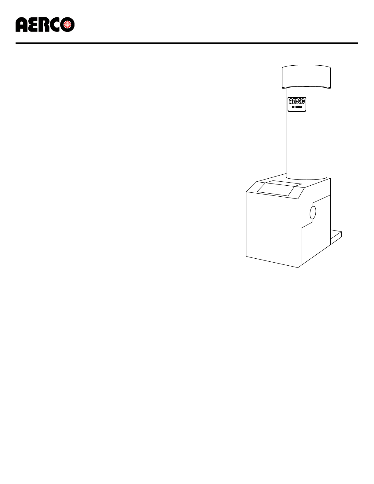
KC Series Gas Fired Water Heater
GF-111
Operation and Maintenance Manual
Applicable to Serial Numbers G-10-1232 and above
KC Series
Gas Fired
Water Heating
System
Natural Gas or Propane Fired,
Condensing and Forced Draft Hot Water Heater
Patent No. 4,852,524
1,000,000 BTU/HR Input
Printed in U.S.A. REVISED 12/10
Page 2
AERCO International, Inc. • 159 Paris Ave. • Northvale, New Jersey 07647 • Phone: 201-768-2400 • FAX: 201-768-7789
KC Series Gas Fired Water Heater
GF-111
Operation and Maintenance Manual
Telephone Support
Direct to AERCO Technical Support
(8 to 5 pm EST, Monday through Friday)
(800) 526-0288
AERCO International, Inc.
159 Paris Avenue
Northvale, NJ 07647-0128
www.aerco.com
© AERCO International, Inc., 2010
The information contained in this operation and maintenance manual is subject
to change without notice from AERCO International, Inc.
AERCO makes no warranty of any kind with respect to this material, including
but not limited to implied warranties of merchantability and fitness for a particular
application. AERCO International is not liable for errors appearing in this manual.
Nor for incidental or consequential damages occurring in connection with the
furnishing, performance, or use of this material.
Printed in U.S.A. REVISED 12/10
Page 3

CONTENTS
Para.
Subject
Page
1.1
Warnings & Cautions
1-1
1.2
Emergency Shutdown
1-2
Para.
Subject
Page
1.3
Prolonged Shutdown
1-2
Para.
Subject
Page
2.1
Receiving the Unit
2-1
2.2
Unpacking
2-1
2.3
Installation
2-2
2.4
Gas Supply Piping
2-4
2.5
Electrical Supply
2-5
Para.
Subject
Page
2.6
Field Control W iring
2-6
2.7
Flue Gas Vent Installation
2-8
2.8
Combustion Air
2-8
Para.
Subject
Page
3.1
Introduction
3-1
3.2
Control Panel Description
3-1
3.3
Control Panel Menus
3-3
3.4
Operating Menu
3-4
3.5
Setup Menu
3-4
Para.
Subject
Page
3.6
Configuration Menu
3-6
3.7
Tuning Menu
3-7
3.8
Start Sequence
3-7
3.9
Start/Stop Levels
3-9
Para.
Subject
Page
4-1
Initial Startup Requirements
4-1
4-2
Tools and Instrumentation for
Combustion Calibration
4-1
4-3
Natural Gas Combustion
Calibration
4-2
Para.
Subject
Page
4-4
Propane Combustion Calibration
4-5
4.5
Unit Reassembly
4-5
4.6
Temperature Control Calibration
4-6
4.7
Over-Temperature Limit Switch
Adjustments
4-7
Para.
Subject
Page
5.1
Testing of Safety Devices
5-1
5.2
Low Gas Pressure Fault Test
5-1
5.3
High Gas Pressure Test
5-1
5.4
Low Water Level Fault Test
5-2
5.5
Water Temperature Fault Test
5-2
5.6
Interlock Tests
5-3
5.7
Flame Fault Test
5-3
5.8
Air Flow Fault Test
5-4
Para.
Subject
Page
5.9
SSOV Proof of Closure Switch
5-4
5.10
Purge Switch Open During
Purge
5-5
5.11
Ignition Switch Open During
Ignition
5-5
GF-111 THE AERCO KC1000 GAS FIRED DOMESTIC WATER HEATER
Operating & Maintenance Instructions
FOREWARD A
Section 1 – SAFETY PRECAUTIONS 1-1
Section 2 – INSTALLATION PROCEDURES 2-1
Section 3 – CONTROL PANEL OPERATING PROCEDURES 3-1
Section 4 – INITIAL START-UP 4-1
Section 5 – SAFETY DEVICE TESTING PROCEDURES 5-1
5.12 Safety Pressure Relief Valve
Test
5-6
i
Page 4

CONTENTS
Para.
Subject
Page
6.1
Maintenance Schedule
6-1
6.2
Spark Ignitor
6-1
6.3
Flame Detector
6-2
6.4
Combustion Calibration
6-2
6.5
Safety Device Testing
6-2
6.6
BTU Transmitter Pump
Lubrication
6-2
Para.
Subject
Page
6.7
BTU Transmitter Assembly
6-3
6.8
Manifold and Exhaust Tubes
6-5
6.9
Heat Exchanger Inspection
6-8
6.10
Condensate Drain Assembly
6-9
Para.
Subject
Page
7.1
Introduction
7-1
Para.
Subject
Page
Para.
Subject
Page
8.1
Introduction
8-1
8.2
RS232 Communication Setup
8-1
Para.
Subject
Page
8.3
Menu Processing Utilizing
RS232 Communication
8-1
8.4
Data Logging
8-2
App
Subject
Page
Descriptions
Messages
Chart
D
Water Heater Default Settings
D-1
App
Subject
Page
E
Dimensional and Parts Drawings
E-1
F
Piping Drawings
F-1
G
Wiring Schematics
G-1
H
KC1000 Control Panel Views
H-1
I
Recommended Spare Parts
I-1
Section 6 – MAINTENANCE 6-1
Section 7 – TROUBLESHOOTING 7-1
Section 8 – RS232 COMMUNICATION 8-1
APPENDICES
A Water Heater Menu Item
B
C
Startup, Status and Fault
Temperature Sensor Resistance
A-1
B-1
C-1
WARRANTIES W-1
ii
Page 5

FOREWORD
Foreword
The AERCO KC Water Heating System is a true industry advance that meets the needs of
today's energy and environmental concerns. Designed for use in any domestic water heating
system, it provides constant temperature water, regardless of flow rate. It’s small space
requirements and venting capabilities allow maximum installation flexibility. The KC Heater’s
load tracking controls modulate over a 20:1 turndown ratio for natural gas units and a 14:1
turndown ratio for propane units to match fluctuating system loads and yield high thermal
efficiencies.
With it’s compact design and direct or chimney venting, the KC Water Heating System is
adaptable to any installation. Efficiency, reliability and longevity make the KC Water Heating
System a true step forward in Water Heating System design.
After prolonged shutdown, it is recommended that the startup procedures in Section 4 and test
procedures in Section 5 of this manual be performed to verify system operating parameters. If
there is an emergency, turn off the electrical power supply to the KC Heater or close the
manual gas valve located before the unit. The installer is to identify the emergency shut-off
device. FOR SERVICE OR PARTS, contact your local sales representative or AERCO
INTERNATIONAL.
NAME:
ORGANIZATION:
ADDRESS:
TELEPHONE:
INSTALLATION DATE: ____________________________________________________
A
Page 6

Page 7

SAFETY PRECAUTIONS
SECTION 1 -- SAFETY PRECAUTIONS
1.1 WARNINGS & CAUTIONS
Installers and operating personnel MUST, at all
times, observe all safety regulations. The
following warnings and cautions are general and
must be given the same attention as specific
precautions included in these instructions. In
addition to all the requirements included in this
AERCO Instruction Manual, the installation of
units MUST conform with local building codes,
or, in the absence of local codes, ANSI Z223.1
(National Fuel Gas Code Publication No. NFPA-
54) for gas-fired heaters and ANSI/NFPASB for
LP gas-fired heaters. Where applicable, the
equipment shall be installed in accordance with
the current Installation Code for Gas Burning
Appliances and Equipment, CGA B149, and
applicable Provincial regulations for the class;
which should be carefully followed in all cases.
Authorities having jurisdiction should be
consulted before installations are made.
See pages 1-2 through 1-4 for important
information regarding installation of units
within the Commonwealth of Massachusetts.
IMPORTANT
This Instruction Manual is an integral part of
the product and must be maintained in
legible condition. It must be given to the user
by the installer and kept in a safe place for
future reference.
IMPORTANT
Read the following restrictions prior to
installing the water heater:
1. The heater can only be used for
applications where the chlorine concentrations Do Not Exceed 4 mg/L which is the
Environmental Protection Agency limit for
chlorine concentrations in drinking water.
2. Do Not use this heater for a pool heating
application.
3. If this heater was ordered with the optional
copper-lined, carbon steel shell, items 1 and
2 Do Not Apply. (Contact your local AERCO
representative to verify heater shell material.
WARNINGS!
MUST BE OBSERVED TO PREVENT
SERIOUS INJURY.
WARNING!
BEFORE ATTEMPTING TO PERFORM ANY MAINTENANCE ON THE
UNIT, SHUT OFF ALL GAS AND
ELECTRICAL INPUTS TO THE UNIT.
WARNING
DO NOT USE MATCHES, CANDLES,
FLAMES, OR OTHER SOURCES OF
IGNITION TO CHECK FOR GAS
LEAKS.
WARNING!
THE EXHAUST VENT PIPE OF THE
UNIT OPERATES UNDER A POSITIVE PRESSURE AND THEREFORE MUST BE COMPLETELY
SEALED TO PREVENT LEAKAGE
OF COMBUSTION PRODUCTS INTO
LIVING SPACES.
WARNING!
FLUIDS UNDER PRESSURE MAY
CAUSE INJURY TO PERSONNEL
OR DAMAGE TO EQUIPMENT
WHEN RELEASED. BE SURE TO
SHUT OFF ALL INCOMING AND
OUTGOING WATER SHUTOFF
VALVES. CAREFULLY DECREASE
ALL TRAPPED PRESSURES TO
ZERO BEFORE PERFORMING
MAINTENANCE.
WARNING!
ELECTRICAL VOLTAGES OF 120
VAC ARE USED IN THIS EQUIPMENT. THEREFORE THE COVER
ON THE UNIT’S POWER BOX
(LOCATED ON THE FRONT RIGHT
SIDE OF THE UNIT UNDER THE
HOOD AND SHEET METAL SIDE
PANEL) MUST BE INSTALLED AT
ALL TIMES, EXCEPT DURING
MAINTENANCE AND SERVICING.
1-1
Page 8

SAFETY PRECAUTIONS
MANUAL GAS SHUTOFF VALVE
VALVE OPEN
VALVE CLOSED
CAUTIONS!
Must be observed to prevent equipment
damage or loss of operating effectiveness.
CAUTION!
Many soaps used for gas pipe leak testing
must
are corrosive to metals. The piping
rinsed thoroughly with clean water after leak
checks have been completed.
be
CAUTION!
DO NOT use this heater if any part has been
under water. Call a qualified service
technician to inspect and replace any part
that has been under water.
1.2 EMERGENCY SHUTDOWN
If overheating occurs or the gas supply fails to
shut off, close the manual gas shutoff valve
(Figure 1-1) located external to the unit.
IMPORTANT
The Installer must identify and indicate the
location of the emergency shutdown manual
gas valve to operating personnel.
1.3 PROLONGED SHUTDOWN
After prolonged shutdown, it is recommended
that the startup procedures in Chapter 4 and the
safety device test procedures in Chapter 5 of
this manual be performed, to verify all systemoperating parameters. If there is an emergency,
turn off the electrical power supply to the
AERCO heater and close the manual gas valve
located upstream the unit. The installer must
identify the emergency shut-off device.
Water heater Installations within the Commonwealth of Massachusetts must conform to the following
requirements:
• Heater must be installed by a plumber or a gas fitter who is licensed within the Commonwealth of
• Prior to unit operation, the complete gas train and all connections must be leak tested using a
• The vent termination must be located a minimum of 4 feet above grade level.
• If side-wall venting is used, the installation must conform to the following requirements extracted
(a) For all side wall horizontally vented gas fueled equipment installed in every dwelling, building or
structure used in whole or in part for residential purposes, including those owned or operated by the
Commonwealth and where the side wall exhaust vent termination is less than seven (7) feet above
finished grade in the area of the venting, including but not limited to decks and porches, the following
requirements shall be satisfied:
Figure 1-1
Manual Gas Shutoff Valve
IMPORTANT – FOR MASSACHUSETTS INSTALLATIONS
Massachusetts.
non-corrosive soap.
from 248 CMR 5.08 (2):
1-2
Page 9

SAFETY PRECAUTIONS
INSTALLATION OF CARBON MONOXIDE DETECTORS
1.
horizontal vented gas fueled equipment, the installing plumber or gasfitter shall observe that a hard wired
carbon monoxide detector with an alarm and battery back-up is installed on the floor level where the gas
equipment is to be installed. In addition, the installing plumber or gasfitter shall observe that a battery
operated or hard wired carbon monoxide detector with an alarm is installed on each additional level of the
dwelling, building or structure served by the side wall horizontal vented gas fueled equipment. It shall be
the responsibility of the property owner to secure the services of qualified licensed professionals for the
installation of hard wired carbon monoxide detectors.
a. In the event that the side wall horizontally vented gas fueled equipment is installed in a crawl
space or an attic, the hard wired carbon monoxide detector with alarm and battery back-up may be
installed on the next adjacent floor level.
b. In the event that the requirements of this subdivision can not be met at the time of completion of
installation, the owner shall have a period of thirty (30) days to comply with the above requirements;
provided, however, that during said thirty (30) day period, a battery operated carbon monoxide
detector with an alarm shall be installed.
. At the time of installation of the side wall
APPROVED CARBON MONOXIDE DETECTORS.
2.
accordance with the above provisions shall comply with NFPA 720 and be ANSI/UL 2034 listed and IAS
certified.
3.
SIGNAGE
building at a minimum height of eight (8) feet above grade directly in line with the exhaust vent terminal
for the horizontally vented gas fueled heating appliance or equipment. The sign shall read, in print size no
less than one-half (1/2) inch in size, "GAS VENT DIRECTLY BELOW. KEEP CLEAR OF ALL
OBSTRUCTIONS".
4.
INSPECTION
equipment shall not approve the installation unless, upon inspection, the inspector observes carbon
monoxide detectors and signage installed in accordance with the provisions of 248 CMR 5.08(2)(a)1
through 4.
(b)
EXEMPTIONS
1. The equipment listed in Chapter 10 entitled "Equipment Not Required To Be Vented" in the most
current edition of NFPA 54 as adopted by the Board; and
2. Product Approved side wall horizontally vented gas fueled equipment installed in a room or
structure separate from the dwelling, building or structure used in whole or in part for residential
purposes.
MANUFACTURER REQUIREMENTS - GAS EQUIPMENT VENTING SYSTEM PROVIDED.
(c)
the manufacturer of Product Approved side wall horizontally vented gas equipment provides a venting
system design or venting system components with the equipment, the instructions provided by the
manufacturer for installation of the equipment and the venting system shall include:
1. Detailed instructions for the installation of the venting system design or the venting system
components; and
2. A complete parts list for the venting system design or venting system.
. A metal or plastic identification plate shall be permanently mounted to the exterior of the
. The state or local gas inspector of the side wall horizontally vented gas fueled
: The following equipment is exempt from 248 CMR 5.08(2)(a)1 through 4:
Each carbon monoxide detector as required in
When
MANUFACTURER REQUIREMENTS - GAS EQUIPMENT VENTING SYSTEM NOT PROVIDED.
(d)
When the manufacturer of a Product Approved side wall horizontally vented gas fueled equipment does
not provide the parts for venting the flue gases, but identifies "special venting systems", the following
requirements shall be satisfied by the manufacturer:
1. The referenced "special venting system" instructions shall be included with the appliance or
equipment installation instructions; and
1-3
Page 10

SAFETY PRECAUTIONS
2. The "special venting systems" shall be Product Approved by the Board, and the instructions for
that system shall include a parts list and detailed installation instructions.
(e) A copy of all installation instructions for all Product Approved side wall horizontally vented gas fueled
equipment, all venting instructions, all parts lists for venting instructions, and/or all venting design
instructions shall remain with the appliance or equipment at the completion of the installation.
______________________________________
[End of Extracted Information From 248 CMR 5.08 (2)]
1-4
Page 11

SECTION 2 - INSTALLATION
2.1 RECEIVING THE UNIT
Each KC1000 Heater is shipped as a single
crated unit. The shipping weight is approximately
1500 lb. and must be moved with the proper rigging equipment for safety and to avoid damage.
The unit should be completely inspected at the
time of receipt from the carrier before the bill of
lading is signed. Each unit has Tip-N-Tell
indicator on the outside of the crate. This
indicates if the unit has been turned on its side.
If the Tip-N-Tell indicator is tripped, do not sign
for the shipment. Note the information on the
carrier’s paperwork and request a freight claim
and inspection by a claims adjuster before
proceeding. Any other visual damage to the
packaging materials should also be made clear
to the delivering carrier.
2.2 UNPACKING
Carefully unpack the unit. Take care not to
damage the unit jacket when cutting away
packaging materials. A close inspection of the
unit should be made to determine if there has
been any damage incurred during shipment that
was not indicated by the Tip-N-Tell indicator.
INSTALLATION
The freight carrier should be notified immediately
if any damage is detected. The following
accessories come standard with each unit and
are packed separately within the unit’s packing
container
• Spare Spark Ignitor
• Spare Flame Detector
• Manual 1-1/4" Gas Shutoff Valve
• Drain Valve Assembly
• ASME Pressure/Temperature
Relief Valve
• Ignitor Removal Tool (One per Site)
• 2 Lifting Lugs
• Stainless Steel Condensate Cup
• Flue Clamps (2 Pieces)
• Shell Cap
• Wing Nut for Shell Cap
Optional accessories are also separately packed
within the unit’s packing container. Standard and
optional accessories shipped with the unit should
be identified and put in a safe place until they are
installed for use.
Figure 2.1 Heater Clearance
2-1
Page 12

INSTALLATION
2.3 INSTALLATION
The unit must be installed with the prescribed
clearances for service as shown in Fig 2.1 These
are the
by AERCO. Local building codes may require
more clearance and take precedence.
KEEP UNIT AREA CLEAR AND FREE
FROM COMBUSTIBLE MATERIALS AND
FLAMMABLE VAPORS AND LIQUIDS.
MASSACHUSSETTS INSTALLATIONS
For water heater installations within the
Commonwealth of Massachusetts, the heater
must be installed by a plumber or a gas fitter
who is licensed within the Commonwealth. In
addition, the installation must comply with all
requirements specified in Section 1 (Safety
Precautions), pages 1-2 through 1-4.
2.3.1 SETTING THE UNIT
Locate the lifting lugs, shipped with the unit, and
attach them to the 5/8” x 11 studs at the top of
the unit. Remove the unit from the wooden skid
and place in position using a block and tackle or
hoist attached to the lifting lugs. (see Fig. 2.2).
USE THE LIFTING LUGS TO MOVE THE
UNIT.
The KC-1000 is U/L approved for installation on
combustible flooring. A 4” to 6" high housekeeping concrete pad is recommended and
allows for sufficient drainage of the condensate.
The unit must be secured using only the holes
provided in the frame base. Do not use piping to
secure the unit in place. See drawing AP-A-576
in Appendix E for the base frame dimensions.
In multiple unit installations, it is important to plan
the position of each unit. Sufficient space for
piping connections and maintenance requirements must be given. All piping must include
ample provision for expansion.
minimum clearance dimensions required
WARNING !
Figure 2.2
Lifting Lug Location
2.3.2 WATER INLET AND OUTLET PIPING
The locations of the 2" NPT cold water inlet and
hot water outlet piping connections are shown in
Figure 2.3. Flow rates through the unit are
limited to 30 gpm continuous and 40 gpm
intermittent.
The heater is shipped with a 2” NPT x 12” long
stainless steel flex connector. It is important that
this flex connector be installed at the hot water
outlet as mentioned in the installation diagrams
to ensure compliance with the AERCO warranty.
If it is desired to install the flex connector
elbowed towards the rear or top of the unit, two
additional parts (not supplied with heater) are
required. These parts are a 2”NPT x 6” long 304
or 316 stainless nipple and a 2” NPT 304 or 316
stainless elbow. Both of these parts must be
capable of withstanding up to 155 psig @ 210°F.
These parts may be added between the heater
outlet connection and the flex connector.
However, if this heater was ordered with the
optional copper-lined carbon steel shell (contact
your local AERCO Representative to verify), it is
not shipped with, and does not require a flex
connector.
2-2
Page 13

INSTALLATION
Shut-off valves and union conections must be
installed in the inlet and outlet lines for maintenance. The use of dielectric unions is recommended. Install the piping and accessories as
per the following drawings, located in Appendix F
of this manual.
• SD-A-424 for single units
• SD-A-425 for multiple units
• SD-A-432 for single units with a stratified
tank
• SD-A-434 for multiple units with a stratified
storage tank
NOTE:
All piping must be arranged so that it does
not interfere with removal of any cover,
inhibit service or maintenance, or prevent
access between the unit and walls, or
another unit.
Figure 2.3
Inlet and Outlet Location
2.3.3 TEST HOSE BIB
A Test Hose Bib connection, upstream of the
shut off valve on the hot water outlet, is required
for startup and testing. It should be a minimum
of 3/4". It cannot be omitted (See Fig. 2.4a)
Figure 2.4a
Hose Bib Location
NOTE:
The maximum working pressure for
installations within the Province of Alberta is
87 psig. Therefore, a pressure & temperature
relief valve with a setting of 75 psig/210°F is
supplied with Alberta shipments. See Drawing
AP-A-863 in Appendix E.
2.3.4 PRESSURE/TEMPERATURE
RELIEF & DRAIN
An ASME rated Pressure/Temperature Relief
Valve is supplied with each unit. With the
exception of Alberta installations (see above
Note), the valve setpoint is 150 psig/210°F.
Install the relief valve as shown in Figure 2.5. A
suitable pipe compound should be used on the
threaded connections. Any excess should be
wiped off to avoid getting any into the valve
body. The relief valve should be pipied to within
12 inches of the floor to prevent injury in the
event of a discharge. The relief piping must be
full size, 1-1/2”, without reduction. No valves,
restrictions, or other blockages are allowed in
the discharge line. In multiple unit installations
the discharge lines must
together. Each must be individually run to a
suitable discharge location.
A 1” drain valve assembly is furnished with each
unit. The assembly should be installed as shown
in Figure 2.4b. The drain should be hard piped to
a suitable drain.
VALVE INSTALLATION
not be manifolded
2-3
Page 14

INSTALLATION
TEMPERATURE SENSOR
EXHAUST
MANIFOLD
CONDENSATE
DRAIN
BURNER
HOSE CLAMP
1-3/4" O.D. x 8-1 /2 “ LG.
SILICONE HOSE
5/8" O.D. TUBE CONN.
CONDENSATE CUP
PLACED ON FLOOR
2.3.5 SYSTEM RECIRCULATION
The system recirculating line ties into the unit at
the recirculating tee fitting provided in the drain
valve assembly (see Fig. 2.4b). Shut off valves
and union connections are recommended for
maintenance. Recirculation flow rates must be
kept to 8 gpm or less. In a multiple unit
installation, each unit must be tied into the
system recirculation system.
4. Replace the rear cover and side panel on the
unit.
Figure 2.5
Condensate Drain Assembly Location
Figure 2.4b
Pressure/Temperature Relief and Drain
Valve Installation Location
2.3.6 CONDENSATE PIPING
The KC Heater is designed to condense.
Therefore, the installation site must include
suitable provisions for condensate drainage or
collection. A stainless steel condensate cup is
separately packed within unit’s shipping
container. To install the condensate cup,
proceed as follows:
1. Remove the left side panel and only the left
half of the rear cover to provide access to the
exhaust manifold and burner (Figure 2.5).
2. Insert the 1-3/4 inch manifold drain hose into
the condensate cup. Allow the cup to rest on
the floor directly beneath the manifold drain
hole (Figure 2.5).
3. Attach a length of 3/4 inch I.D.polypropylene
tubing to the condensate cup drain tube and
route it to a floor drain. . If a floor drain is not
available, a condensate pump can be used to
remove the condensate to drain. The
condensate drain line must be removable for
routine maintenance.
2.4 GAS SUPPLY PIPING
AERCO Gas Fired Equipment Gas Components
and Supply Design Guide (GF-1030) should be
consulted before any gas piping is designed or
started.
WARNING !
DO NOT USE MATCHES, CANDLES,
FLAMES OR OTHER SOURCES OF
IGNITION TO CHECK FOR GAS LEAKS
.
CAUTION !
Many soaps used for gas pipe leak testing
are corrosive to metals. The piping must be
rinsed thoroughly with clean water after
leak checks have been completed
.
NOTE:
All gas piping must be arranged so that it
does not interfere with removal of any
cover, inhibit service or maintenance, or
prevent access between the unit and walls,
or another unit
The location of the 1-1/4" inlet gas connection
on the right side of the unit is shown in Figure
2.6.
.
2-4
Page 15

INSTALLATION
gas trains at 1,000,000 BTU/H for natural
gas and propane units.
The maximum static inlet pressure to the unit
must be no more than 14” W.C.. Minimum gas
pressure is 8.5” W.C. for FM gas trains and 8.9”
W.C. IRI gas trains when the unit is firing at
maximum input. Gas pressure should not
exceed 10.5” W.C. at any time when the unit is
firing. Proper sizing of the gas supply regulator in
delivering the correct gas flow and outlet
pressure is mandatory. The gas supply pressure
regulator must maintain the gas pressure at a
minimum of 8.5” W.C. (FM) or 8.9” W.C. (IRI)
when the unit is at maximum BTU input
(1,000,000 BTU/HR). The supply gas regulator
must be able to supply sufficient capacity
Figure 2.6
Gas Supply Regulator and Manual Shut -
Off Valve Location
All pipe should be de-burred and internally
cleared of any scale or iron chips prior to
installation. No flexible connectors or nonapproved gas fittings should be installed. Piping
should be supported from floor or walls only and
must not be secured to the unit.
A suitable piping compound approved for use
with gas should be used sparingly. Any excess
must be wiped off to prevent clogging of
components.
To avoid damage to the unit when pressure
testing gas piping, isolate the unit from the gas
supply piping. At no time should there be more
than 1 psig maximum to the unit. Bubble test all
external piping thoroughly for leaks using a soap
and water solution or suitable equivalent. The
gas piping must meet all applicable codes.
2.4.1 GAS SUPPLY PRESSURE
REGULATOR
A mandatory external, in line, supply gas
regulator (supplied by others) should be
positioned as shown in Figure 2.6. Union
connections should be placed in the proper
locations to allow maintenance of the regulator if
required.
NOTE:
An individual gas pressure regulator must
be installed upstream of each unit. The
regulator must regulate gas pressure to 8.5”
W.C. for FM gas train and 8.9” W.C. for IRI
volume, (1000 cfh), to the unit and should have
no more than 1" droop from minimum to full fire.
The supply gas regulator must also be rated to
handle the maximum incoming gas pressure.
When the gas supply pressure will not exceed
14” W.C. a non-lock up, or flow through style
regulator, may be used. When supply gas
pressure will exceed 14” W.C., a lock up style
regulator must be used. The gas supply
regulator must be propery vented to outdoors.
Consult the local gas utility for exact
requirements concerning venting of supply gas
regulators.
CAUTION
A lockup style regulator must be used when
gas supply pressure exceeds 14” W.C.
2.4.2 MANUAL GAS SHUTOFF VALVE
A 1-1/4” manual gas shutoff valve is furnished
with each unit and should be positioned as
shown in Figure 2.6. The valve must be installed
upstream of the gas supply regulator in a readily
accessible location.
2.4.3 IRI GAS TRAIN KIT
The IRI gas train is an optional gas train required
in some areas by code or for insurance purposes. The IRI gas train comes pre-assembled
and wired from the factory. See Appendix E,
Drawing SD-A-606.
The IRI gas train may be ordered pre-assembled
or as separate components. If either IRI gas
train option is ordered, a complete instructional
package, detailing field installation will be
included. To obtain a copy of an IRI instructional
package prior to the equipment shipping contact
your local representative or AERCO.
2-5
Page 16

INSTALLATION
POWER BOX
BLOWER
SSOV
ACTUATOR
FRAME
USE COPPER CONDUCTORS ONLY FOR FIELD WIRING
60 HZ
DISCONNECT POWER BEFORE SERVICING
DANGER: HIGH VOLTAGE
20 AMP
120 VAC,
NEUTRAL
GROUND
LINE
POWER BOX
AERCO INTERNATIONAL INC.
INPUT POWER
GAS SHUT-OFF VALVE
I/O BOX
BLOWER
2.5 ELECTRICAL SUPPLY
The AERCO Gas Fired Equipment Electrical
Power Wiring Guide, (GF-1060), must be
consulted in addition to the following material
before wiring to the unit is started. AC power
connection to the unit are made at the Power
Box.This box is located on the front right side of
the unit as shown in Figure 2.7.
All electrical conduit and hardware should be
installed so that it does not interfere with the
removal of any cover, inhibit service or
maintenance, or prevent access between the
unit and walls or another unit.
2.5.1 ELECTRICAL REQUIREMENTS
Electrical requirements for each unit are 120
VAC, 1 Phase, 60 Hz, 20 Amps from a dedicated
electrical circuit. No other devices should be on
the same electrical circuit as a KC1000 unit.
Figure 2.7
AC Power Box Location
NOTE:
covers. A flexible electrical connection may be
utilized to allow the covers to be easily removed.
Figure 2.8
AC Power Wiring Diagram
2.6 FIELD CONTROL WIRING
Each unit is fully wired from the factory with an
internal operating control system. No field control
wiring is required for normal operation. However,
the KC1000 control system does allow for some
control and monitoring features. W iring for these
features can be accomplished in the I/O Box
behind the left side panel (Figures 2.9 and 2.10).
The I/O Box is common to both KC1000 water
heaters and boilers. While some of the inputs
and outputs are common to both water heaters
and boilers, some are not applicable to both.
These are noted in the following paragraphs.
CAUTION!
DO NOT make any connections to the I/O
Box terminals labeled “NOT USED”.
Attempting to do so may cause equipment
damage.
A means for disconnecting AC power from the
unit (such as a service switch) must be installed
near the unit for normal operation and
maintenance. All electrical connections should
be made in accordance with the National
Electrical Code and/or with any applicable local
codes.
The electrical wiring diagram is shown in Figure
2.8. Conduit should be run from the knockouts in
the side of the box in such a manner that it does
not interfere with the removal of any sheet metal
2-6
Figure 2.9
Input/Output (I/O) Box Location
Page 17

INSTALLATION
2.6.1 OUTDOOR AIR SENSOR IN
Not applicable to Water Heaters.
2.6.2 AUX SENSOR IN
The AUX SENSOR IN terminals can be used to
add an additional temperature sensor for
monitoring purposes. This input is always
enabled and is a view only input that can be
seen in the operating menu. The sensor must be
wired to the AUX SENSOR IN and SENSOR
COMMON and must be similar to AERCO
BALCO wire sensor P/N 12449. A resistance
chart for this sensor can be found in Appendix C.
2.6.3 ANALOG IN
The ANALOG IN + and – terminals are used
when an external signal is used to change the
setpoint of the water heater when operating in
the Remote Setpoint Mode.
Either a 4 to 20 mA / 1 to 5 VDC or a 0 to 20 mA/
0 to 5 VDC signal may be used to vary the
setpoint or air/fuel valve position. The factory
default setting is for 4 to 20 mA / 1 to 5 VDC,
however this may be changed to 0 to 20 mA / 0
to 5 VDC using the Configuration Menu
described in Section 3. If voltage rather than
current is selected as the drive signal, a DIP
switch must be set on the CPU Board located
inside the Control Box. Contact the AERCO
factory for information on setting DIP switches.
All supplied signals must be floating
(ungrounded) signals. Connections between the
source and the Heater’s I/O Box must be made
using twisted shielded pair wire of 18 –22
AWG,,such as Belden 9841(see Fig. 2.10).
Polarity must be maintained and the shield must
be connected only at the source end. It must be
left floating (not connected) at the Heater’s I/O
Box.
Whether using voltage or current for the drive
signal, they are linearly mapped to a 40°F to
240°F setpoint or a 0% to 100% valve position.
No scaling for these signals is provided
2.6.4 B.M.S. (PWM) IN
Not applicable to Water Heaters.
2.6.5 SHIELD
The SHIELD terminals are used to terminate any
shields used on sensor wires connected to the
unit. Shields must only be connected to these
terminals.
2.6.6 mA OUT
These terminals provide a 4 to 20 mA output that
can be used to monitor setpoint ( to 220°F),
outlet temperature ( to 245°F), or valve position
(0% to 100%). This function is enabled in the
Configuration Menu (Section 3, Table 3.4).
2.6.7 RS-485 COMM
These terminals are used for RS-485 MODBUS
serial communication between the unit and an
external “Master”, such as an Energy Management System.
2.6.8 EXHAUST SWITCH IN
These terminals permit an external exhaust
switch to be connected to the exhaust manifold
of the boiler. The exhaust sensor should be a
normally open type switch (such as AERCO P/N
123463) that closes (trips) at 500°F.
2.6.9 INTERLOCKS
The unit offers two interlock circuits for
interfacing with Energy Management Systems
and auxiliary equipment such as pumps or
louvers or other accessories. These interlocks
are called the Remote Interlock and Delayed
Interlock (Fig. 2.10). The wiring terminals for
these interlocks are located inside the I/O Box
on the left side of the unit. The I/O Box cover
contains a wiring diagram which shows the
terminal strip locations for these interlocks
labeled REMOTE INTL’K IN and DELAYED
INTL’K IN. Both interlocks, described below, are
factory wired in the closed position.
NOTE:
Both the Delayed Interlock and Remote
Interlock must be in the closed position to
allow the unit to fire.
2.6.9.1 REMOTE INTERLOCK IN
The remote interlock circuit (REMOTE INTL’K
IN) is provided to remotely start (enable) and
stop (disable) the unit if desired. The circuit is
24 VAC and comes factory pre-wired closed
(jumped).
2.6.9.2 DELAYED INTERLOCK
The delayed interlock circuit (DELAYED INTL’K
IN) is typically used in conjunction with the
auxiliary relay described in paragraph 2.6.11.
This interlock circuit is located in the purge
section of the start string. It can be connected to
the proving device (end switch, flow switch etc.)
of an auxiliary piece of equipment started by the
unit’s auxiliary relay. The delayed interlock must
be closed for the heater to fire. If the delayed
interlock is connected to a proving device that
2-7
Page 18

INSTALLATION
mA OUT
RS-485
COMM.
+
-
+
-
ANALOG IN
SENSOR COMMON
OUTDOOR SENSOR IN
REMOTE INTL'K IN
B.M.S. (PWM) IN
SHIELD
+
-
+
-
AUX SENSOR IN
NOT USED
EXHAUST SWITCH IN
DELAYED INTL'K IN
FAULT RELAY
120 VAC, 5A, RES
AUX RELAY
120 VAC, 5A, RES
G
RELAY CONTACTS:
120 VAC, 30 VDC
5 AMPS RESISTIVE
DANGER
120 VAC USED
IN THIS BOX
NOT USED
NOT USED
NC
COM
NO
NC
COM
NO
NOT USED
requires time to close (make), a time delay (Aux
Start On Dly) that holds the start sequence of the
unit long enough for a proving switch to make
(close) can be programmed. Should the proving
switch not prove within the programmed time
frame, the unit will shut down. The Aux Start On
Dly can be programmed from 0 to 120 seconds.
This option is locate in the Configuration Menu
(Section 3).
2.6.10 FAULT RELAY
The fault relay is a single pole double throw
(SPDT) relay having a normally open and
normally closed set of relay contacts that are
rated for 5 amps at 120 VAC and 5 amps at 30
VDC. The relay energizes when any fault
condition occurs and remains energized until the
fault is cleared and the CLEAR button is
depressed. The fault relay connections are
shown in Figure 2.10.
2.6.11 AUXILIARY RELAY CONTACTS
Each unit is equipped with a single pole double
throw (SPDT) relay that is energized when there
is a demand for heat and de-energized after the
demand for heat is satisfied. The relay is
provided for the control of auxiliary equipment,
such as pumps and louvers, or can be used as a
unit status indictor (firing or not firing). Its
contacts are rated for 120 VAC @ 5 amps.
Refer to Figure 2.10 to locate the AUX RELAY
terminals for wiring connections.
2.7 FLUE GAS VENT INSTALLATION
AERCO Gas Fired Venting and Combustion Air
Guide, GF-1050, must be consulted before any
flue or combustion air venting is designed or
installed. Suitable, U/L approved, positive
pressure, watertight vent materials MUST be
used for safety and UL certification. Because
the unit is capable of discharging low
temperature exhaust gases, the flue must be
pitched back towards the unit a minimum of 1/4"
per foot to avoid any condensate pooling and to
allow for proper drainage.
2-8
Figure 2.10 I/O Box Wiring
While there is a positive flue pressure during
operation, the combined pressure drop of vent
and combustion air systems must not exceed
140 equivalent feet of 0.81” W.C. Fittings as
well as pipe lengths must be calculated as part
of the equivalent length. For a natural draft
installation the draft must not exceed - 0.25”
W.C. These factors must be planned into the
vent installation. If the maximum allowable
equivalent lengths of piping are exceeded, the
unit will not operate properly or reliably.
Page 19

INSTALLATION
For Massachusetts installations, the Heatfab
Division of the Selkirk Corporation provides vent
systems which conform to all applicable
requirements for installations within the
Commonwealth of Massachusetts. Contact
information for this supplier are as follows:
Selkirk Corporation
Heatfab Division
130 Industrial Blvd.
Turners Falls, MA 01376
Phone: 1-800-772-0739
.heat-fab.
2.8 COMBUSTION AIR
The AERCO Gas-Fired Heater Venting and
Combustion Air Guide, GF-1050 MUST be
consulted before any flue or inlet air venting is
designed or installed. Air supply is a direct
requirement of ANSI 223.1, NFPA-54, and local
codes. These codes should be consulted before
a permanent design is determined.
The combustion air must be free of chlorine,
halogenated hydrocarbons or other chemicals
that can become hazardous when used in gasfired equipment. Common sources of these
compounds are swimming pools, degreasing
compounds, plastic processing, and refrigerants.
Whenever the environment contains these types
of chemicals, combustion air MUST be supplied
from a clean area outdoors for the protection
and longevity of the equipment and warranty
validation.
The more common methods of combustion air
supply are outlined below. For combustion air
supply from ducting, consult AERCO GF-1050,
Gas Fired Venting and Combustion Air Guide.
2.8.1 COMBUSTION AIR FROM OUTSIDE THE BUILDING
Air supplied from outside the building must be
provided through two permanent openings. For
each unit these two openings must have a free
area of not less than one square inch for each
4000 BTUs input of the equipment or 250 square
inches of free area. The free area must take into
account restrictions such as louvers and bird
screens.
2.8.2 COMBUSTION AIR FROM INSIDE THE BUILDING
When combustion air is provided from within the
building, it must be supplied through two permanent openings in an interior wall. Each opening
must have a free area of not less than one
square inch per 1000 BTUH of total input or
1000 square inches of free area. The free area
must take into account any restrictions such as
louvers.
2.8.3 SEALED COMBUSTION
The unit is UL approved for a 100% sealed
combustion application when installed properly.
When a sealed combustion air application is
installed, the sealed combustion air piping must
be deducted from the maximum allowable
discharge piping amounts. Each unit must have
a minimum 6" diameter connection made to the
optional Inlet Air Adapter # GM-18917 available
from AERCO. This Adapter bolts directly on to
the air inlet of the unit blower. See installation
instructions with Adapter. All inlet air ducts must
be sealed air tight.
2-9
 Loading...