

Page 1
Instruction
No.
AERCO INTERNATIONAL, Inc., Northvale, New Jersey, 07647 USA
GF-105
Installation, Operation
& Maintenance Instructions
KC Series
Gas Fired
Water Heating
System
Natural Gas or Propane Fired,
Condensing and Forced Draft Hot Water Heater
1,000,000 BTU/HR Input
Applicable to Serial Numbers G-01-026 and above
Patent No. 4,852,524
Printed in U.S.A. REVISED 12/30/04
Page 2

Telephone Support
Direct to AERCO Technical Support
(8 to 5 pm EST, Monday through
Friday)
(800) 526-0288
AERCO International, Inc.
159 Paris Avenue
Northvale, NJ 07647-0128
© AERCO International, Inc., 2004
The information contained in this operation
and maintenance manual is subject to
change without notice from AERCO
International, Inc.
AERCO makes no warranty of any kind with
respect to this material, including but not
limited to implied warranties of
merchantability and fitness for a particular
application. AERCO International is not
liable for errors appearing in this manual.
Nor for incidental or consequential damages
occurring in connection with the furnishing,
performance, or use of this material.
Page 3

CONTENTS
GF-105 THE AERCO KC1000 GAS FIRED DOMESTIC WATER HEATER
Operating & Maintenance Instructions
FOREWORD
Section 1 SAFETY PRECAUTIONS--------------------------------1
Section 2 INSTALLATION PROCEDURES-----------------------2
2.1 Receiving the Unit
2.2 Unpacking
2.3 Installation
2.4 Gas Supply Piping
2.5 Electrical Supply
Section 3 CONTROL PANEL COMPONENTS
3.1 The Control Panel
3.2 The Temperature Contro ller
3.3 The Primary Menu
3.4 The Secondary Menu
3.5 The Annunciator Circuit
3.6 The Combustion Safeguard
Controller
Section 4 INITIAL START-UP--------------------------------------17
4.1 Initial Start-Up req uir ements
4.2 Tools and Instrumentation f or
Combustion Calibration
4.3 Combustion Calibration
4.4 Propane Combustion Calibration
2.6 Field Control Wiring
2.7 Flue Gas Vent Installation
2.8 Combustion Air
2.9 Unit Initial Fill
and OPERATING PROCEDURES------------9
3.7 Water Level T est and Reset Switches
3.8 On\Off Switch
3.9 Starting Sequence
3.10 After Flame
3.11 Flame Test Jacks
3.12 Start\Stop Levels
3.13 Auto Restarts
4.5 Unit Reassembly
4.6 Temperature Control Calibration
4.7 Over Temperature Limit Switch
Adjustments
Section 5 SAFETY DEVICE TESTING
5.1 Testing of Safety Devices
5.2 Gas Pressure Fault Test
5.3 Low Water Level Fault Test
5.4 Water Temperature Fault Test
PROCEDURES-----------------------------------25
5.5 Flame Fault Test
5.6 Air Pressure Fault Test
5.7 Purge Interlocks Fault Test
5.8 Safety Pressure Relief Valve Test
i
Page 4

CONTENTS
Section 6 MAINTENANCE REQUIREMENTS-------------------29
6.1 Maintenance Schedule
6.2 Spark Ignitor
6.3 Flame Detector
6.4 Combustion Calibration
6.5 Safety Device Testing
Section 7 TROUBLESHOOTING-----------------------------------39
7.1 Gas Pressure Fault
7.2 Exhaust Temperature Fault
7.3 Water Level Fault
7.4 Water Temperature Fault
A. Temperature Controller Menus
B. Temperature Controller Quick
Programming Guide
C. Shell Sensor Resistance Chart
D. Mode of Operation Default
Settings
6.6 BTU Transmitter Pump
Lubrication
6.7 BTU Transmitter Assembly
6.8 Manifold and Exhaust Tubes
6.9 Heat Exchanger Inspection
7.5 Flame Fault
7.6 Air Pressure Fault
7.7 System Fault
APPENDICES
E. Dimensional & Parts Drawings
F. Piping Drawings
G. Wiring Schem atics
H. Control Panel Isometric Drawing
WARRA NTIES
2/27/99
ii
Page 5

FOREWORD
Foreword
The AERCO KC Hot Water Heating System is a true industry advance that meets the needs of
today’s energy and environmental concerns. Designed for use in any potable water heat ing
system, it provides constant temperature water regardless of flow rate. It’s small space
requirements and venting capabilities allows installations without norm al restrictions yet with
maximum flexibility. The KC Heater’s load tracking controls modulate over a 14:1 turndown ratio
to match the system demand and yield thermal efficiencies in excess of 93%.
Because of its compact design with direct or chimney venting, the KC Water Heating System is
applicable to any installation with excellent results. Eff iciency, reliability and longevity make the
KC Water Heat ing System a true step forward in Water Heating System design.
After prolonged shutdown, it is recom mended that the startup procedures in Section 4 and t est
procedures in Section 5 of this manual be performed, to verify system operating parameters. If
there is an emergency, turn off the electrical power supply to the AERCO Heater or close the
Manual Gas Valve located before the AERCO heater. T he I nstaller is to identify the emergency
shut-off device. FOR SERVI CE OR PARTS, contact your local Sales Representative listed below
or AERCO INTERNATIONAL.
NAME:
ORGANIZATION:
ADDRESS:
TELEPHONE:
INSTALLATION DATE: _____________________________________________
iii
Page 6
SECTION 1 -- SAFETY PRECAUTIONS
Installing or operating per sonnel MUST, at
all times, observe all safety regulations.
The following warnings are general and
must be given the same attention as
specific precautions included in these
instructions. In addition to the
requirements included in this instruct ion
manual, the installation of units MUST
conform with local building codes, or, in
the absence of local codes, ANZI Z223.1
(National Fuel Gas Code, Publication No.
NFPA-54) for gas-fired heaters and
ANSI/NFPASB for LP gas-fired heaters.
Where applicable, t he equipment shall be
installed in accordance with CGA B149.
SAFETY PRECAUTIONS
WARNING!
DO NOT USE MATCHES, CANDLES,
FLAMES, OR OTHER SOURCES OF
IGNITION TO CHECK FOR GAS LEAKS.
WARNING!
THE EXHAUST VENT PIPE OPERATES
UNDER POSITIVE PRESSURE AND
MUST BE COMPLETELY SEALED TO
PREVENT LEAKAGE OF COMBUSTION
PRODUCTS INTO LIVING SPACES
.
WARNINGS!
MUST BE OBSERVED TO PREVENT
SERIOUS INJURY TO PERSONNEL
.
WARNING!
BEFORE PERFORMING ANY
MAINTENANCE ON THE UNIT,
SHUT OFF THE GAS SUPPLY AND THE
ELECTRICAL POWER SUPPLY TO THE
UNIT.
WARNING!
FLUIDS UNDER PRESSURE MAY
CAUSE INJURY TO PERSONNEL OR
DAMAGE TO EQUIPMENT WHEN
RELEASED.. BE SURE TO SHUT OFF
ALL INCOMING AND OUTGOING
WATER SHUTOFF VALVES AND
CAREFULLY DECREASE ALL TRAPPED
PRESSURES TO ZERO BEFORE
PERFORMING ANY MAINTENANCE.
CAUTIONS!
Must be observed to prevent equipment
damage or loss of operating
effectiveness.
CAUTION!
Many soaps used for gas pipe leak testing
are corrosive to metals. The piping m ust
be rinsed thoroughly with clean water after
leak checks have been completed.
CAUTION!
Do not use this unit if any part has been
under water. Call a qualified service
technician to inspect and replace any
part that has been under water.
NOTES:
Must be observed for effective operating
procedures & conditions
1
Page 7
INSTALLATION PROCEDURES
SECTION 2 - INSTALLATION PROCEDURES
2.1 RECEIVING THE UNIT
Each KC unit is shipped as a single crated unit.
The shipping weight is approximately 1500 lb.
and must be moved with the proper rigging
equipment for safety and to avoid damages.
The unit should be completely inspected at the
time of receipt from the carrier before the bill of
lading is signed. Each unit has Tip-N-Tell
indicator on the outside of the crate. This
indicates if the unit has been turned on its side.
If the Tip-N-Tell indicator is tripped, do not sign
for the shipment. Note the information on the
carrier’s paperwork and request a freight claim
and inspection by a claims adjuster before
proceeding. Any other visual damage to the
packaging materials should also be made clear
to the delivering carrier.
2.2 UNPACKING
Carefully unpack the unit by removing the
packaging material. Take care not to damage
the unit jacket when cutting away packaging
materials. A close inspection of the unit should
be made to determine if there has been any
damage during shipment that was not indicated
by the Tip-N-Tell.
The freight carrier should be notified immediately
if any damage is detected. The following
accessories come standard with each unit and
are packed separately within the unit’s packing
container
• Spare Spark Ignitor
• Spare Flame Detector
• Manual 1-1/4" Gas Shutoff Valve
• Drain Valve Assembly
• ASME Pressure/Temperature
Relief Valve
• Ignitor Removal Tool (O ne per Site)
• Regulator Adjustment Tool (One
• per Site)
• 2 Lifting Lugs
• Stainless Steel Condensate Cup
• Flue Clamps (2 Pieces)
Optional accessories are also separately packed
within the unit’s packing container. Standard and
optional accessories shipped with the unit
should be identified and put in a safe place until
installation/use.
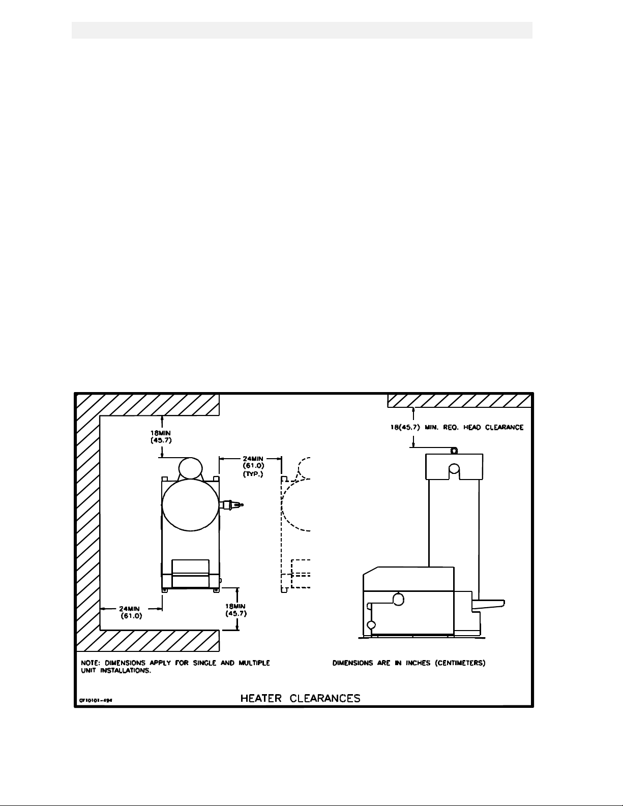
Figure 2.1
Heater Clearances
2
Page 8
INSTALLATION PROCEDURES
2.3 INSTALLATION
The unit must be installed with the prescribed
clearances for service as shown in Fig 2.1
These are the minimum clearance dimensions
required by AERCO. Local building codes may
require more clearance and take precedence.
WARNING !
KEEP UNIT AREA CLEAR AND FREE
FROM COMBUSTIBLE MATERIALS AND
FLAMMABLE VAPORS AND LIQUIDS.
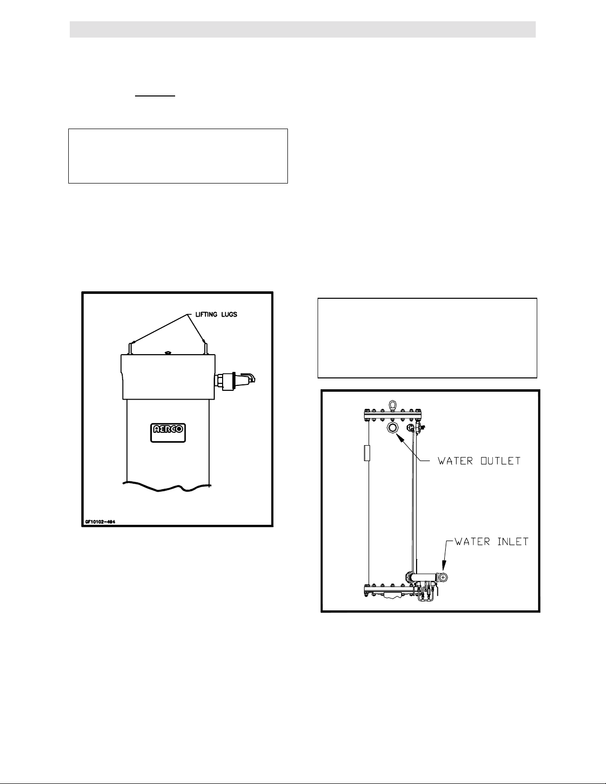
2.3.1 SETTING THE UNIT
Locate the lifting lugs, shipped with the unit, and
attach them to the 5/8” x 11 studs at the top of
the unit. Remove the unit from the wooden skid
and place in position using a block and tackle or
hoist attached to the lifting lugs. (see Fig. 2.2).
USE THE LIFTING LUGS TO MOVE THE
UNIT.
2.3.2 WATER INLET AND O UTLET
PIPING
The locations of the 2" NPT cold water inlet and
hot water outlet piping connections are shown in
Figure 2.4. Flow rates through the unit are
limited to 30 gpm continuous and 40 gpm
intermittent.
Shut-off valves and union conections must be
installed in the inlet and outlet lines for
maintenance. The use of dielectric unions is
recommended. Install the piping and
accessories as per the following drawings,
located in Appendix F of this manual.
• SD-B-424 for single units
• SD-B-425 for multiple units
• SD-B-432 for single units with a stratified
tank
• SD-B-434 for multiple units with a stratified
storage tank
NOTE:
All piping must be arranged so that it does
not interfere with removal of any cover,
inhibit service or maintenance, or prevent
access between the unit and walls, or
another unit.
Figure 2.2
Lifting Lug Location
The KC-1000 is U/L approved for installation on
combustible flooring. A 4” to 6" high
housekeeping concrete pad is recommended
and allows for sufficient drainage of the
condensate.
The unit must be secured using only the holes
provided in the frame base. Do not use piping to
secure the unit in place. See drawing AP-A-576
in Appendix E for the base frame dimensions.
In multiple unit installations it is important to
plan the position of each unit. Sufficient space
for piping connections and maintenance
requirements must be given. All piping must
include ample provision for expansion.
Figure 2.3
Inlet and Outlet Location
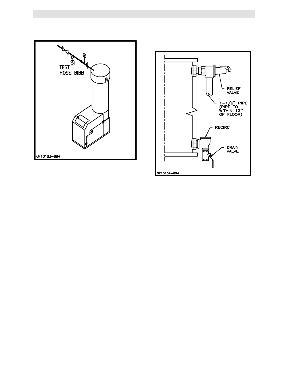
2.3.3 TEST HOSE BIB
A Test Hose Bib connection, upstream of the
shut off valve on the hot water outlet, is required
3
Page 9
INSTALLATION PROCEDURES
for startup and testing. It should be a minimum
of 3/4". It cannot be omitted (See Fig. 2.4a)
maintenance. Recirculation flow rates must be
kept to 8 gpm or less. In a multiple unit
installation, each unit must be tied into the
system recirculation system.
Figure 2.4a
Hose Bibb Location
2.3.4 PRESSURE/TEMPERATURE
RELIEF AND DRAIN
VALVE
INSTALLATION
An ASME rated Pressure/Temperature Relief
Valve is supplied with each unit. The valve
setpoint is 150 psig/210
valve as shown in Fig. 2.4. A suitable pipe
compound should be used on the threaded
connections. Any excess should be wiped off to
avoid getting any into the valve body. The relief
valve should be pipied to within 12 inches of the
floor to prevent injury in the event of a
discharge. The relief piping must be full size, 11/2”, without reduction. No valves, restrictions,
or other blockages are allowed in the discharge
line. In multiple unit installations the discharge
lines must not be manifolded together. Each
must be individually run to a suitable discharge
location.
A 1” drain valve assembly is furnished with each
unit. The assembly should be installed as shown
in Figure 2.4. The drain should be hard piped to
a suitable drain.
0
F. Install the relief
Figure 2.4b
Pressure/Temperature Relief and Drain
Valve Installation Location
2.3.6 CONDENSATE PIPING
The KC Heater is designed to condense and the
installation must have provisions for suitable
drainage. A 1 inch ID silicone hose, supplied
with the unit, directs condensate from the
exhaust manifold to a stainless steel condensate
cup. The condensate cup is shipped loose and
should be installed inside the unit directly under
the manifold’s condensate drainage hole. The
condensate drain fitting is attached to the cup
and should be located at the rear of the unit as
shown in Figure 2.5. A 5/8-inch ID flexible
polypropylene tubing (or suitable equivalent)
should be used to carry the condensate by
gravity to a nearby floor drain. If a floor drain is
not available, a condensate pump can be used
to remove the condensate to a convenient drain.
The maximum condensate flow rate is 5 GPH.
The condensate cup and line must be
removable for routine maintenance. Do not
hard pipe.
2.3.5 SYSTEM RECIRCULATION
The system recirculating line ties into the unit at
the recirculating tee fitting provided in the drain
valve assembly (see Fig. 2.4b). Shut off valves
and union connections are recommended for
4
Page 10

Figure 2.5
Condensate Drain Assembly Location
2.4 GAS SUPPLY PIPING
AERCO Gas Fired Equipment Gas Components
and Supply Design Guide (GF-1030) should be
consulted before any gas piping is designed or
started.
INSTALLATION PROCEDURES
A suitable piping compound approved for use
with gas should be used sparingly. Any excess
must be wiped off to prevent clogging of
components.
To avoid damage to the unit when pressure
testing gas piping, isolate the unit from the gas
supply piping. At no time should there be more
than 1 psig maximum to the unit. Bubble test all
external piping thoroughly for leaks using a soap
and water solution or suitable equivalent. The
gas piping must meet all applicable codes.
WARNING !
DO NOT USE MATCHES, CANDLES,
FLAMES OR OTHER SOURCES OF
IGNITION TO CHECK FOR GAS LEAKS
.
CAUTION !
Many soaps used for gas pipe leak testing
are corrosive to metals. The piping m ust be
rinsed thoroughly with clean water after
leak checks have been completed.
NOTE:
All gas piping must be arranged so that it
does not interfere with removal of any
cover, inhibit service or maintenance, or
prevent access between the unit and walls,
or another unit
The location of the 1-1/4" inlet gas connection
on the right side of the unit is shown in Figure
2.6.
All pipe should be de-burred and internally
cleared of any scale or iron chips before
installation. No flexible connectors or nonapproved gas fittings should be installed. Piping
should be supported from floor or walls only and
must not be secured to the unit.
.
Figure 2.6
Gas Supply Regulator and Manual Shut -
Off Valve Location
2.4.1 GAS SUPPLY PRESSURE REGULATOR
A mandatory external, in line, supply gas
regulator (supplied by others) should be
positioned as shown in Figure 2.6. Union
connections should be placed in the proper
locations to allow maintenance of the regulator if
required.
NOTE:
An individual gas pressure regulator must
be installed upstream of each unit. The
regulator must regulate gas pressure to
8.5” W . C. for FM gas train and 8.9” W.C. for
IRI gas trains at 1,000,000 BTU/H for
natural gas and propane units.
The maximum static inlet pressure to the unit
must be no more than 14” water column.
Minimum gas pressure is 8.5” W.C. for FM gas
trains and 8.9” W.C. IRI gas trains when the unit
is firing at maximum input. Gas pressure should
5
Page 11
INSTALLATION PROCEDURES
not exceed 10.5” W.C. at any time when the unit
is firing. Proper sizing of the gas supply regulator
in delivering the correct gas flow and outlet
pressure is mandatory. The gas supply pressure
regulator must maintain the gas pressure at a
minimum of 8.5” W.C. (FM) or 8.9” W.C. (IRI)
when the unit is at maximum BTU input
(1,000,000 BTU/HR). The supply gas regulator
must be able to supply sufficient capacity
volume, (1000 cfh), to the unit and should have
no more than 1" droop from minimum to full fire.
The supply gas regulator must also be rated to
handle the maximum incoming gas pressure.
When the gas supply pressure will not exceed
14” W.C. a non-lock up, or flow through style
regulator, may be used. When supply gas
pressure will exceed 14” W.C., a lock up style
regulator must be used. The gas supply
regulator must be propery vented to outdoors.
Consult the local gas utility for exact
requirements concerning venting of supply gas
regulators.
CAUTION!
A lockup style regulator must be used when
gas supply pressure exceeds 14” W. C.
ELECTRICAL WIRING BOX
FRAME
SSOV
ACTUATOR
BLOWER
Figure 2.7
AC Wiring Box Location
2.4.2 MANUAL GAS SHUTOFF VALVE
A 1-1/4” manual gas shutoff valve is furnished
with each unit and should be positioned as
shown in Figure 2.6. The valve must be installed
upstream of the gas supply regulator in a readily
accessible location.
2.4.3 IRI GAS TRAIN KIT
The IRI gas train is an optional gas train required
in some areas by code or for insurance
purposes. The IRI gas train may be ordered preassembled or as separate components. If either
IRI gas train option is ordered a complete
instructional package, detailing field installation
will be included. To obtain a copy of an IRI
instructional package prior to the equipment
shipping contact your local representative or
AERCO.
2.5 ELECTRIC SUPPLY
AERCO Gas Fired Equipment Electrical Power
Wiring Guide (GF-1060) must be consulted in
addition to the following material before wiring to
the unit is started. The location of the electrical
wiring box is on the front right side of the unit as
shown in Figure 2.7.
NOTE:
All electrical conduit and hardware should
be installed so that it does interfere with the
removal of any cover, inhibit service or
maintenance, or prevent access between
the unit and walls or another unit.
2.5.1 ELECTRICAL REQUIREMENTS
Electrical requirements for each unit are 120
VAC, 1 Phase, 60 Hz, 20 Amps from a
dedicated electrical circuit. No other devices
should be on the same electrical circuit as a KC
unit. A disconnecting means such as a service
switch must be installed near the unit for normal
operation and maintenance. All electrical
connections should be made in accordance with
the National Electrical Code and/or with any
applicable local codes.
The electrical wiring diagram is shown in Figure
2.8. Conduit should be run from the knockouts
provided in the side of the electrical box in such
a manner that it does not interfere with the
removal of any sheet metal covers. A flexible
electrical connection may be utilized to allow the
covers to be removed easily.
6
Page 12
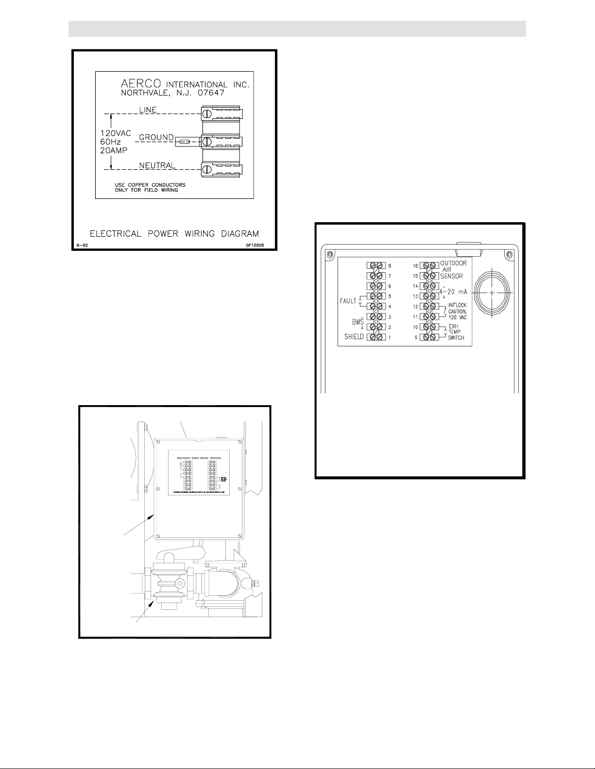
Figure 2.8
Electrical W ir ing Diagram
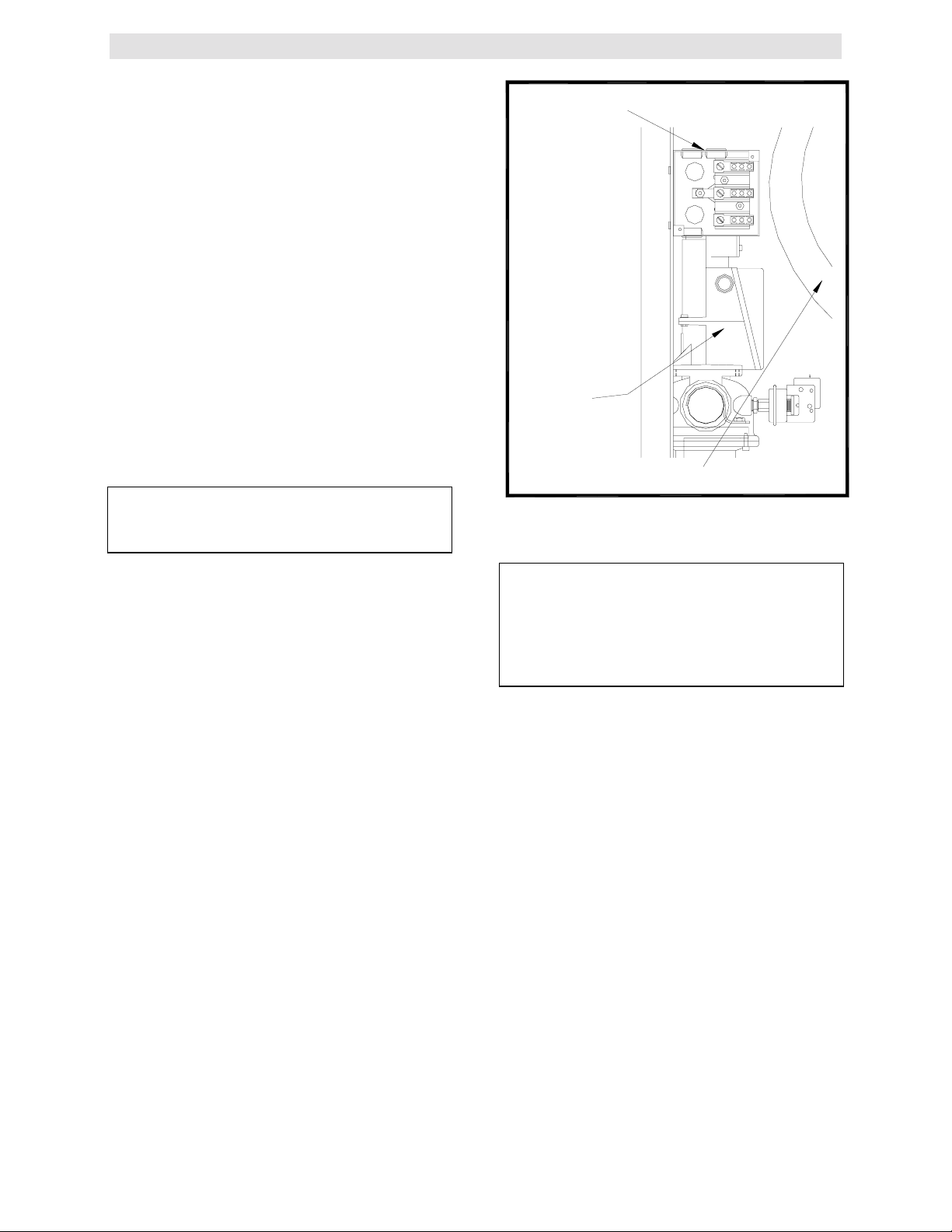
2.6 FIELD CONTROL WIRING
Each unit is fully wired from the factory with an
internal operating control system. No field control
wiring is required for normal operation. However
a fault relay, for remote fault indication, and
enable/disable interlock circuits are provided.
Wiring for these circuits can be accomplished in
the Field Control Wiring Box behind the left side
panel (see Fig. 2.9).
INSTALLATION PROCEDURES
This interlock must be closed,(jumped), to allow
the unit to fire. When the interlock is open, the
control panel Annunciator will display
'INTERLOCK DISABLED' and the unit will not
fire. The unit comes factory wired with the
interlock closed.
2.6.2 THE FAULT RELAY
The fault relay is a single pole single throw relay,
that is energized upon any fault condition. The
relay will remain energized until the fault is
cleared and the CLEAR button is pushed The
normally open field connections are shown in
Figure 2.10. The relay contacts are rated for 5
amps at 250 VDC and 5 amps at 30 VDC.
AERCO INTERNATIONAL INC.
BLOWER
FIELD WIRING
816
OUTDOOR
START
INDICATION
FAULT
-
BMS
+
SHIELD
AIR
SENSOR
7
15
6
14
4-20 mA
5
13
+
4
12
3
11
2
10
EXH.
TEMP.
SWITCH
1
9
FIELD
CONTROL
WIRING
BOX
GAS SHUT-OFF VALVE
Figure 2.9
Field Control W ir ing Box Location
2.6.1 ENABLE/DISABLE INTERLOCK
Each unit has an enable/disable interlock circuit
located in the field wiring box (see Figure 2.10).
Figure 2.10
Field Control Box Wir ing
2.7 FLUE GAS VENT INSTALLATION
AERCO Gas Fired Venting and Combustion Air
Guide, GF-1050, must be consulted before any
flue or combustion air venting is designed or
installed. Suitable, U/L approved, positive
pressure, watertight vent materials MUST be
used for safety and UL certification. Because
the unit is capable of discharging low
temperature exhaust gases, the flue must be
pitched back towards the unit a minimum of 1/4"
per foot to avoid any condensate pooling and to
allow for proper drainage.
While there is a positive flue pressure during
operation, the combined pressure drop of vent
and combustion air systems must not exceed
140 equivalent feet of 0.81” W.C. Fittings as
well as pipe lengths must be calculated as part
7
Page 13

INSTALLATION PROCEDURES
of the equivalent length. For a natural draft
installation the draft must not exceed - 0.25”
W.C. These factors must be planned into the
vent installation. If the maximum allowable
equivalent lengths of piping are exceeded, the
unit will not operate properly or reliably.
2.8 COMBUSTION AIR
The AERCO Gas-Fired Heater Venting and
Combustion Air Guide, GF-1050 MUST be
consulted before any flue or inlet air venting is
designed or installed. Air supply is a direct
requirement of ANSI 223.1, NFPA-54, and local
codes. These codes should be consulted before
a permanent design is determined.
The combustion air must be free of chlorine,
halogenated hydrocarbons or other chemicals
that can become hazardous when used in gasfired equipment. Common sources of these
compounds are swimming pools, degreasing
compounds, plastic processing, and refrigerants.
Whenever the environment contains these types
of chemicals, combustion air MUST be supplied
from a clean area outdoors for the protection
and longevity of the equipment and warranty
validation.
The more common methods of combustion air
supply are outlined below. For combustion air
supply from ducting, consult the AERCO GF1050, Gas Fired Venting and Combustion Air
Guide.
2.8.1 COMBUSTION AIR FROM OUTSIDE
THE BUILDING
Air supplied from outside the building must be
provided through two permanent openings. For
each unit these two openings must have a free
area of not less than one square inch for each
4000 BTUs input of the equipment or 250 square
inches of free area. The free area must take into
account restrictions such as louvers and bird
screens.
be deducted from the maximum allowable
discharge piping amounts. Each unit must have a
minimum 6" diameter connection made to the
optional Inlet Air Adapter # GM-18917 available
from AERCO. This Adapter bolts directly on to
the air inlet of the unit blower. See installation
instructions with Adapter. All inlet air ducts must
be sealed air tight.
2.9 UNIT INITIAL FILL
Before filling the shell for the first time, blow out
all the connecting water and gas piping and
check thoroughly for leaks. Rinse all soap suds
from the gas piping with clean water. Do not
allow water to get on the Control Panel or
electrical connections. Check that all installation
procedures have been completed.
The following steps should be followed to fill the
unit:
1. Close the unit’s drain valve.
2. Open the shut-off valves at the water inlet
and outlet.
3. Open the temperature/pressure relief valve
to allow air to escape from the shell. The
shell is full when water flows out of relief
valve discharge piping.
4. Close the temperature/pressure relief valve
and open fixtures in building to free the
system of air.
2.8.2 COMBUSTION AIR FROM INSIDE
THE BUILDING
When combustion air is provided from within the
building, it must be supplied through two
permanent openings in an interior wall. Each
opening must have a free area of not less than
one square inch per 1000 BTUH of total input or
1000 square inches of free area. The free area
must take into account any restrictions such as
louvers.
2.8.3 SEALED COMBUSTION
The unit is UL approved for a 100% sealed
combustion application when installed properly.
When a sealed combustion air application is
installed, the sealed combustion air piping must
8
Page 14
CONTROL PANEL OPERATING PROCEDURES
SECTION 3- CONTROL PANEL OPERATING PROCEDURES
The following is a guide to the operation of the
unit’s control panel. Initial startup of this unit must
be performed by factory trained startup personnel.
Operation prior to initial startup by factory trained
personnel will void the warranty.
CAUTION:
All initial installation procedures must be
satisfied before attem pt ing to start the unit
WARNING:
DO NOT ATTEMPT TO DRY FIRE THE KC
1000. STARTING THE UNIT WITHO UT A
FULL WATER LEVEL CAN SERIOUSLY
DAMAGE THE UNIT AND MAY RESULT IN
PERSONNEL INJURY OR PROPERTY
DAMAGE. THIS SITUATION WILL VOID
ANY WARRANTY.
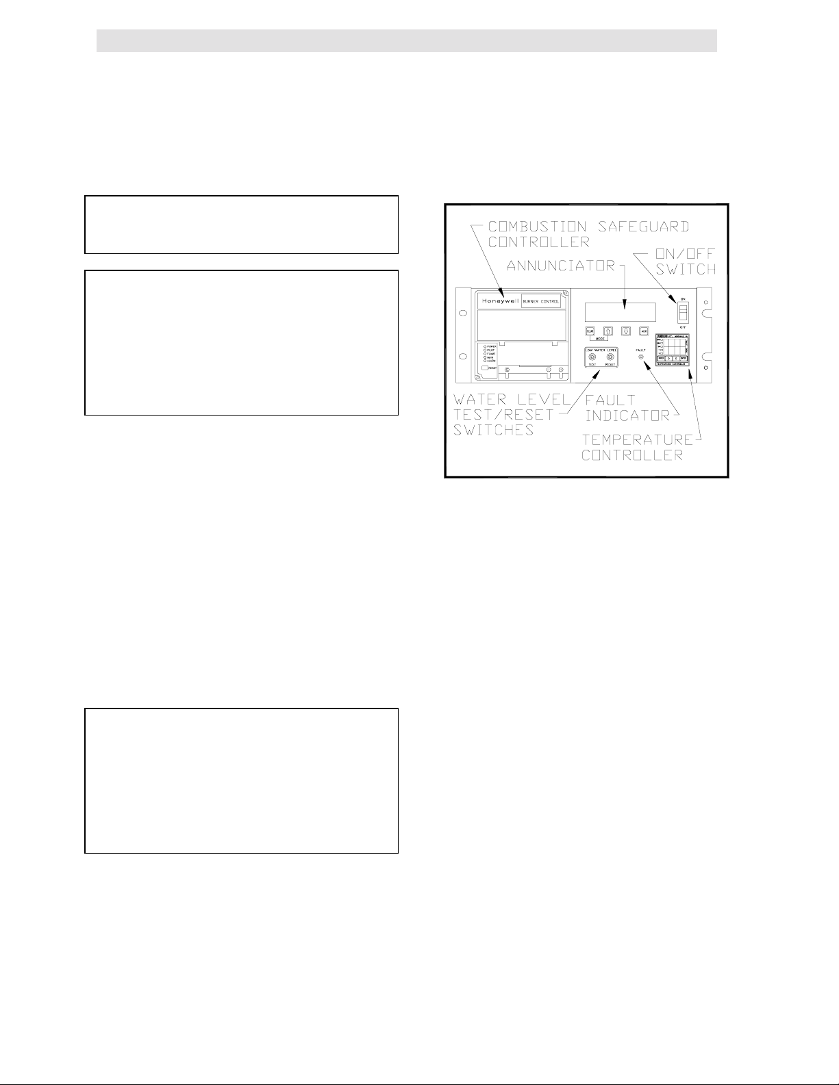
3.1 THE CONTROL PANEL
The KC 1000 Control Panel has been designed to
provide the operator with all the necessary
information required for operation and
troubleshooting the unit. There are six separate
accessible controls or displays, available to the
operator (see Figure 3.1). These are:
1. The Temperature Controller
2. The Annunciator & Function Switches
3. The Combustion Safeguard Controller
4. Water Level Test and Reset Switches
5. On/Off Switch
6. Fault Indicator Light
The following sections will describe the above
components in more detail.
WARNING
CONTROL BOX INTERNALS MUST NOT
BE SERVICED OR ACCESSED BY OTHER
THAN FACTORY CERTIFIED SERVICE
TECHNICIANS. ALL CONTROL BOX
INTERNALS HAVE THE CAPABILITY OF
HOLDING AN ELECTRICAL VOLTAGE OF
120 VOLTS AC.
3.2 THE TEMPERATURE CONTROLLER
The temperature controller is a PID
programmable controller that utilizes feed forward
and feedback information to accurately maintain a
desired set point. It is the primary source for
programming and viewing operating parameter
settings. It also plays a part in the start sequence
and includes other features such as:
• 2- eight segment LED displays
• 5 indicator status lights
• 3 menu levels
• RS-485 communications capability,
.
FIGURE 3.1
Front Panel Controls Location
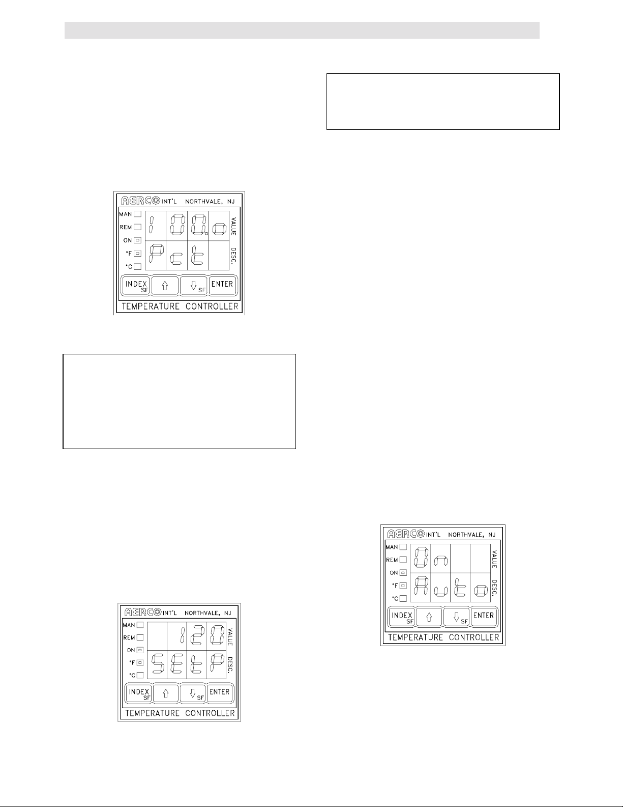
3.2.1 LED DISPLAYS
The upper and lower displays each consist of four
8 segment LED’s’ (see figure 3.2). When an
operating parameter is chosen to be changed or
looked at, the lower led display indicates the
parameter being looked at in the form of a code.
The upper display indicates the parameter’s value.
For a complete listing of the operating parameters
see Appendix A of this manual.
3.2.2 INDICATOR STATUS LIGHTS
The first LED indicator light, “MAN”) indicates
whether the controller is in auto or manual mode,
(see Fig. 3.2). When lit the controller is in manual
mode and the operator is responsible for
operation of the unit. When the LED is not lit the
controller is in auto mode. In auto mode the
controller is operating the unit from signals
generated by sensors located on the unit.
The second LED, “REM”, designates whether the
controller is being controlled locally or remotely.
(see Fig. 3.1). When lit the controller is in remote
mode and can accept commands from an
external source via the RS-485 interface. When
this LED is not lit the controller is in local mode
and will respond to whatever the current internal
settings are. All external commands are ignored.
9
Page 15

CONTROL PANEL OPERATING PROCEDURES
The third LED, “ON”, indicates the status of the
start relay, (Fig. 3.2). The start relay is internal to
the controller and is part of the start string for the
unit. When this LED is lit there is a demand for
heat and the start relay is closed.
o
The last two LED’s, “
whether the temperature displayed is °F or °C.
F” and “oC”, indicate
NOTE:
When the t em per ature controller is
displaying in oC only the temperature being
displayed is affected. All other set t ings
remain in oF.
Figure 3.2
Temperature Controller Operating Status
Lights
menu parameter are listed within this section. For
more data concerning the minimum and
maximum range, and factory defaults of menu
parameters, see the Appendix D of this manual.
3.3 PRIMARY MENU
The primary menu is the default menu. When in
another menu level and there is no activity for
five minutes the temperature controller will
default back to the primary menu. The Primary
menu allows the operator access to the controller
parameters listed below.
Code Meaning
tout Actual unit outlet water temperature.
pct Current firing rate of the unit in
percent.
Setp The desired set-point of outlet water
temperature.
Auto Automatic controlling mode ON or
OFF.
3.3.1 OUTLET TEMPERATURE (TOUT)
Outlet temperature is the actual outlet water
temperature of the unit. To access outlet
temperature, press the INDEX button until (tout) is
displayed in the lower LED. The variable under
this feature may not be manually changed. Fig 3.3,
below, shows an outlet temperature of 120º F
3.2.3 MENU LEVELS
The temperature controller has two menu levels
that are operator accessible for programming the
unit functions and parameters. These are the
Primary and Secondary menus.
To change from the primary menu to the
secondary menu simultaneously depress the
arrow key and ENTER button. To change from
the secondary to the primary menu
simultaneously press the ⇓ arrow key and the
INDEX button.
To scroll through a menu, depress the INDEX
button. To change a parameter scroll through the
menu until the desired parameter is indicated on
the controller’s lower LED display. Then use the
!
and " arrow keys to change the parameters
value. Once the desired parameters value has
been changed the ENTER key must be pushed
for the change to be recognized by the controller.
Leaving the desired parameter without entering
the new value will result in that parameter value
defaulting back to the previous value. Detailed
descriptions and instructions for accessing each
!
Figure 3.3
Outlet Temperature Display
3.3.2 PERCENTAGE OF FIRING RATE
(Pct)
Percentage of firing rate is a number, in percent,
that is related to the input BTU’s of the unit. For
instance a 50% signal equals approximately
500,000 BTU gas input while a 75 % signal equals
approximately 750,000 BTU gas input.
CAUTION:
Do not leave the unit unattended while in the
manual mode of operation.
10
Page 16
CONTROL PANEL OPERATING PROCEDURES
To access the percent of firing rate press the
INDEX button while in the primary menu until
(Pct) is displayed in the lower LED. Use the
arrow key to increase or decrease the percentage
of firing rate. Press the ENTER button to accept
the desired change. Figure 3.4 shows the
temperature controller displaying a 100% firing
rate.
!, "
Figure 3.4
Percent of Firing Rate Display
WARNING:
WHEN SWITCHING FROM AUTO TO
MANUAL MODE, THE FIRING RATE DOES
NOT CHANGE. THE UNIT WILL CONTINUE
TO OPERATE AT THE SAME FIRING RATE
PERCENTAGE AS WHEN THE UNIT WAS
IN AUTO MODE.
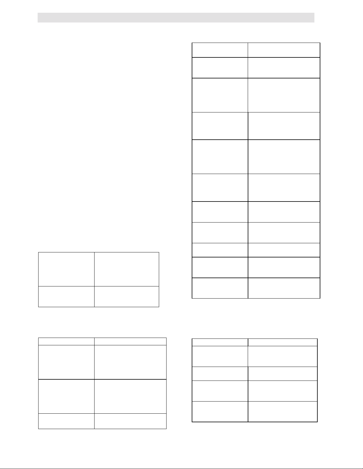
3.3.3 SETPOINT (SETP)
Setpoint is the desired outlet water temperature
that is to be maintained by the unit when in
automatic mode. Fig 3.5 shows the controller with
a setpoint of 120º F.
NOTE:
Changing the setpoint will only be
recognized when the unit is in the automatic
mode.
3.3.4 AUTOMATIC\MANUAL (AUTO)
When set to automatic mode the controller is
receiving and processing inputs from temperature
sensor(s) located externally or on the unit. The
controller uses these inputs to automatically
decrease or increase the firing rate to match the
load.
In manual mode the controller no longer
automatically controls the firing rate of the unit. It
is up to the operator to control the outlet
temperature and firing rate. Manual mode is
commonly used for service and troubleshooting
the unit. All safety limits remain functional
whether the controller is in automatic or manual
mode.
To place the controller in automatic mode press
the INDEX button until (Auto) is displayed in the
lower LED.
!
Now press the
displayed in the upper LED, (see Fig. 3.6). Press
the enter button to accept the change. The MAN
LED should not be lit.
To place the KC 1000 in manual mode, press the
! "
arrow keys until OFF is displayed in the
upper LED (See Fig. 3.7). Press the enter button
to accept the change. The MAN LED should now
be lit.
" arrow keys until ON is
To access the unit’s setpoint press the INDEX
button until (Setp) is displayed in the lower LED.
To increase or decrease the unit’s setpoint press
! "
the
accept the change.
arrow keys. Press the ENTER button to
Figure 3.5
Setpoint Display
Figure 3.6
Auto/Manual Display with Auto On
11
Page 17

CONTROL PANEL OPERATING PROCEDURES
Figure 3.7
Auto/Manual Display with Manual ON
3.4 SECONDARY MENU
The secondary menu is primarily related to
temperature control. It is necessary to access this
menu when temperature calibrating the unit.
To access the secondary menu, press the
arrow key and ENTER simultaneously. To scroll
through the menu press the INDEX button. The
secondary menu allows access to the following
temperature control features:
!
For a complete explanation of the secondary
menu parameters see the Appendix A of this
manual.
3.5 THE ANNUNCIATOR CIRCUIT
The annunciator consists of the annunciator
circuit board, the front panel LCD display, and 4
function switches (see Fig. 3.8). The annunciator
circuit board is the interface between the LCD
display and the combustion safeguard system. It
monitors the unit during every phase of operation
and prompts the LCD display with start sequence
and fault messages. The function switches are
used to reset the annunciator and gain access to
the annunciator’s three function displays.
Func
tout
FFt
Pct
SetP
SEnS
OFSt
LLt
HLt
Pb1 Proportional Band
Int Integral Rate
Drt Derivative Time
Fdb Feedback on or off
Addr
LOre
Unit’s mode of
operation
Outlet water
temperature
Water temperature
at the BTU
transmitter sensor
Firing rate of the unit
in percent
The desired set point
of outlet water temp
High flow
temperature
adjustment
Low flow
temperature
adjustment
Low temperature
alarm
High temperature
alarm
Controller address
for external
communication
Local/ remote status
of the control
Figure 3.8
Annunciator Function Switches and LCD
Display
The annunciator circuit board and LCD display
are not an integral part of the start sequence or
combustion safeguard system. If either should fail
the unit will still operate with no adverse effects.
The annunciator start sequence messages, fault
messages, function switches and function displays
are explained below.
3.5.1 ANNUNCIATOR FUNCTION
DISPLAYS AND SWITCHES
The annunciator has three function displays that
are available to the operator. These are the
MAIN, the CYCLES, and the SET DATE displays.
These displays are accessed using the four
membrane switches located directly under the
12
Page 18
CONTROL PANEL OPERATING PROCEDURES
LCD display on the front of the control panel.
!, "
They are labeled CLEAR,
The MAIN display is used during normal operation
of the unit. In the MAIN display, start sequence
and fault messages can be viewed. To return to
the MAIN display from any other display,
simultaneously press CLEAR and the
key. To reset the MAIN display after a fault has
occurred press the CLEAR button.
The CYCLES display indicates the date and time,
and the number of cycles the unit has started.
When in the CYCLES display only the number of
cycles can be reset. To reset the number of cycles
to zero, simultaneously press the
keys and hold them for approximately four
seconds.
In the SET DATE display, both the time and date
are displayed and can be changed.
To access the SET DATE display, press the
CLEAR button while in the CYCLES display.
Continue pressing the CLEAR button to move
through the SET DATE display fields. Use the
"
arrow keys to set the date and time.
The following table shows the messages
displayed after accessing the CYCLES and SET
DATE DISPLAYS.
The number of times
# CYCLES =
“DATE” “TIME”
SET DATE:
“DATE” “TIME”
completed it’s start
cycle, and the time
Displays and allows
setting of the date
, and AUX.
!
arrow
! "
arrow
the controller has
and date
and time
!
3.5.2 ANNUNCIATOR FAULT MESSAGES
The following table lists the Annunciator fault
messages and their meanings.
LOW WATER
LEVEL
REMOTE
DISABLED
PURGE INTLK
OPEN
LOW AIR FLOW
SYSTEM FAULT
PURGE
INTERLOCKS
SYSTEM FAULT
LOW AIR
PRESSURE
FLAME FAULT
DURING
IGNITION TRIAL
LOCKOUT RUN
AIR FLOW
LOCKOUT RUN
FLAME
LOCKOUT RUN
HI EXHAUST
TEMP
The unit water level is
below the probe level.
The interlock terminals,
in the relay box, are not
closed.
The proof of closure
switch or the purge
switch did not prove
closed during the start
sequence.
The air flow switch did
not proved closed
during the start
sequence.
The proof of closure
switch or purge switch
did not proved closed 45
seconds after the unit
attempted to start.
The air pressure switch
did not prove closed 45
seconds after the unit
attempted to start.
Flame did not prove at
the end of the trial for
ignition period.
The air pressure switch
opened after flame was
proven.
Flame signal was lost
after flame was proven.
The combustion
safeguard is locked out.
The exhaust gas
temperature has
exceeded 500º F
3.5.3 ANNUNCIATOR START SEQUENCE
MESSAGES
The following table lists the annunciator start
sequence messages.
MESSAGE MEANING
AC power has been
RESET MAIN
POWER
HIGH WATER
TEMP
LOW GAS
PRESSURE
interrupted. Power must
be shut off for 20
seconds to reset the
display.
Outlet water
temperature has
exceeded the high
temperature limit
setting.
The unit has tripped due
to low gas pressure.
13
MESSAGE MEANING
The unit is in standby
STANDBY
PURGING The unit is in the 7 sec
IGNITION TRIAL
FLAME PROVEN
mode waiting for a call
for heat
purge.
The unit is in ignition
position attempting to
light the burner
The unit has
established flame and
is running normally.
Page 19
CONTROL PANEL OPERATING PROCEDURES
3.6 THE COMBUSTION SAFEGUARD
CONTROLLER
The Combustion Safeguard is responsible for
monitoring the safety components during the start
sequence, and after flame is established. It is also
responsible for timing of the purge and ignition
cycles during the start sequence.
The combustion safeguard is located on the left
side of the control panel as shown in Figure 3.9.
There are five status LEDs that indicate the
status of operation. Along with the annunciator,
these are useful as a double check for proper
system operation and troubleshooting. The table
below defines the function of each light. The
reset button located under the LEDs is to reset
the combustion safeguard on lockout.
DESCRIPTION FUNCTION
POWER
PILOT
FLAME
MAIN
ALARM
Lights upon power up of
the unit.
Lights when there is a call
for heat.
Lights once flame has
been detected.
Lights after flame has
been detected and
stabilized
This lights when the
controller is in a LOCKOUT
condition.
3.7 WATER LEVEL TEST and RESET
SWITCHES
The water level switches are located on the left
side of the panel (see Fig. 3.10). When depressed
the TEST switch simulates a low water level
condition by breaking the connection between the
water level probe and the sensing circuitry. To test
the water level circuitry, depress the test switch for
3 seconds. The unit should fault resulting in the
red fault light blinking and the LED display
indicating LOW WATER LEVEL.
Figure 3.10
Water Level Test and Reset Switch Locations
Figure 3.9
Combustion Safeguard Status Indicator LED
Location
Note:
Only water level circuitry is tested during the
above test. To determine if the probe is
functioning properly, the water level must be
reduced below the level of the probe.
To reset the unit, depress the water level reset
switch, the annunciator clear button, and if
necessary, the reset button on the combustion
safeguard.
3.8 ON/OFF SWITCH
The ON/OFF switch is located on the right side of
the control box above the temperature controller
(see Figure 3.1). It is part of the start string and
must be in the ON position to enable the unit to
fire. When the switch is in the ON position and
illuminated, it is indicating that the start limit
string, consisting of water temperature, gas
pressure, water level, and the interlock is
satisfied. The unit, at this point, is in standby
mode and ready to run.
14
Page 20
CONTROL PANEL OPERATING PROCEDURES
3.9 START SEQUENCE
When the unit is in the standby mode, and there
is a demand for hot water, the following will occur:
1. Upon demand the temperature controller’s ON
status indicator will light.
2. The combustion safeguard’s PILOT LED
lights, and the blower contactor energizes,
starting the blower.
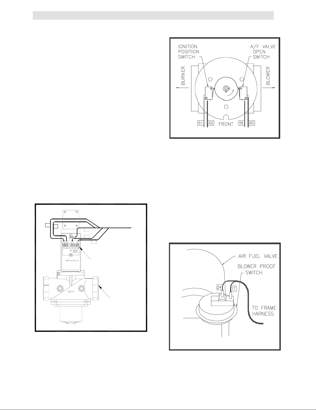
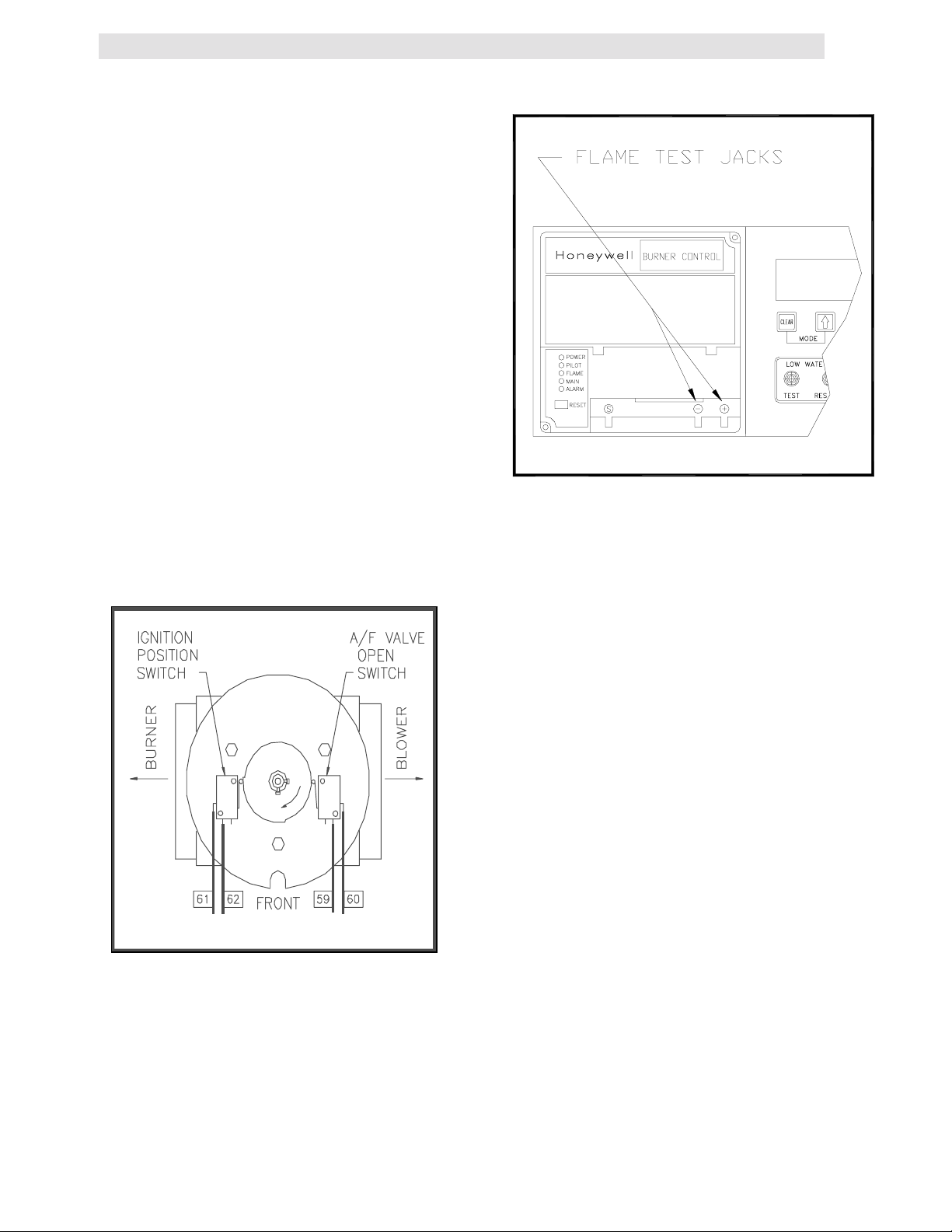
3. The system next checks for proof of closure
from the safety shut-off valve, (see Fig. 3.11),
and the air fuel valve rotates open engaging
the air /fuel valve open switch (see Fig. 3.12).
4. The LCD display shows PURGE INTLK OPEN
until the above conditions are met. Once met
the LCD display will show LOW AIR FLOW.
5. The blower proof switch closes, (See Fig.
3.13), and the LCD display will show
PURGING.
6. Closure of the blower proof switch signals the
combustion safeguard to begin its 7-second
purge cycle.
145
146
147
149
148
FROM
CONNECTOR
9A
Figure 3.12
Air/Fuel Valve Open and Engaging the
Air/Fuel Valve Open Microswitch
7. At the end of the purge cycle the combustion
safeguard initiates a 10 second trial for ignition
and the following simultaneously occurs:
• The LCD displays the message IGNITION
TRIAL.
• The ignition transformer energizes.
• The air/fuel valve rotates to its low fire
position. This engages the air-fuel valve
closed switch, energizing the safety shut-off
valve, (see Fig. 3.14).
PROOF OF
CLOSURE
SWITCH
SAFETY
SHUT-OFF
VALVE
Figure 3.11
Proof of Closure Switch Location
Figure 3.13
Blower Proof Switch Location
8. Once the combustion safeguard detects
flame, its flame LED lights. Power is removed
15
Page 21
CONTROL PANEL OPERATING PROCEDURES
from the ignition transformer and the MAIN
LED lights of the combustion safeguard.
At this point, the annunciator will display FLAME
PROVEN. The unit, in the automatic mode, is
released to modulate through the PID controls.
3.10 AFTER FLAME
Once the control signal has gone below the stop
level (see section 3.12 for Stop Level explanation),
the temperature controller’s green ON light
extinguishes, indicating there is no longer a call for
heat. This signals the combustion safeguard to
shut down the burner. The POWER LED of the
combustion safeguard remains illuminated and the
annunciator displays the message STANDBY.
3.11 FLAME TEST JACKS
The front of the combustion safeguard has two
test jacks marked + and - for flame monitoring,
(see Fig. 3.15). To access the test jacks remove
the combustion safeguard cover by turning the
center screw counterclockwise. A standard
voltmeter is required to monitor the flame signal
strength. A flame signal of 1.5 to 5VDC is typical
during proper operation of the unit.
Figure 3.15
Flame Test Jack Location
3.12 START STOP LEVELS
The start and stop levels are the firing rate
percentages that represent a call for heat and an
indication that the call for heat has been satisfied.
The start level is preset to 20% and the stop level
is preset to 16%. These are factory preset and
should not require adjustment.
Figure 3.14
Air/Fuel Valve in Ignition Position, Engaging
the Ignition Microswitch
16
Page 22

SECTION 4 - INITIAL START UP
INITIAL START-UP
4.1 INITIAL START- UP REQUIREMENTS
The Initial Start-Up of the KC-1000 Boiler is
comprised of the following steps:
• installation completed 100%
• combustion calibration
• proper setting of controls and limits
• temperature calibration
• safety device testing (see Section 5)
Installation procedures should be completed
100% before performing initial start-up and the
start-up must be complete prior to putting the
unit into service. Starting a unit without the
proper piping, venting, or electrical systems can
be dangerous and void the product’s warranty.
These start-up instructions should be precisely
followed in order for the unit to operate safely, at
a high thermal efficiency, and with low flue gas
emissions.
Initial unit start-up is to be performed ONLY by
AERCO factory trained start-up and service
personnel. After following the steps in this
section, it will be necessary to perform the mode
of operation settings in section 5, and the safety
control test procedures in section 6 to complete
the initial unit start-up.
An AERCO Gas Fired Startup Sheet included
with each KC-1000 must be completed for each
unit for warranty validation and a copy must be
returned promptly to AERCO at:
AERCO International, Inc.
159 Paris Ave.
Northvale, NJ 07647
WARNING
!
DO NOT ATTEMPT TO FIRE THE UNIT
WITHOUT FULL WATER LEVEL. THI S
CAN SERIOUSLY DAMAGE THE UNIT
AND MAY RESULT IN PERSONAL
INJURY OR PROPERTY DAMAGE. THIS
IS NOT COVERED BY WARRANTY.
CAUTION!
All installation procedures in Section 2 must
be completed before attempting to start the
unit.
4.2 TOOLS AND INSTRUMENTATION
FOR COMBUSTION CALIBRATION
To properly perform combustion calibration, the
proper instruments and tools must be used and
correctly installed on the unit. The following
sections outline the necessary tools and
instrumentation as well as their installation.
4.2.1 REQUIRED TOOLS AND
INSTRUMENTATION
The following tools and instrumentation are
necessary to perform combustion calibration of
the unit:
1. A digital combustion analyzer with oxygen
accuracy to 0.4%, and carbon monoxide in
PPM
2. ** A 16" W.C. manometer and plastic tubing
3. Three, 1/8" NPT to barbed fittings for use
with manometers
4. Aerco differential gas pressure regulator
adjustment tool P/N GM-122643 (one
supplied per installation)
5. Small and large flat blade screwdrivers
6. 7/16" open end wrench and small adjustable
wrenches
7. Tube of silicone adhesive
8. * Digital multimeter with 10 amp and volt
capability
*Although not necessary for actual start-up
procedures, recommended for troubleshooting.
**For propane fired units: an additional 8" W.C.
manometer and 1/2" NPT to barbed fitting is
needed.
4.2.1 INSTALLING THE SUPPLY GAS
MANOMETER
1. Close the manual gas supply valve upstream
of the unit.
2. Remove the 1/8" NPT pipe plug from the gas
train assembly. This pipe plug is located
below the low gas pressure switch before
the safety shut off valve (see Fig. 4.1).
3. Install a barbed fitting into the pipe plug
tapping.
4. Attach one end of a length of plastic tubing
to the barbed fitting and one end to the 16"
W.C. manometer.
17
Page 23
1/4" NPT PLUG
(INSTALL
MANOMETER
HERE)
SSOV
Figure 4.1
1/8” Gas Plug Location
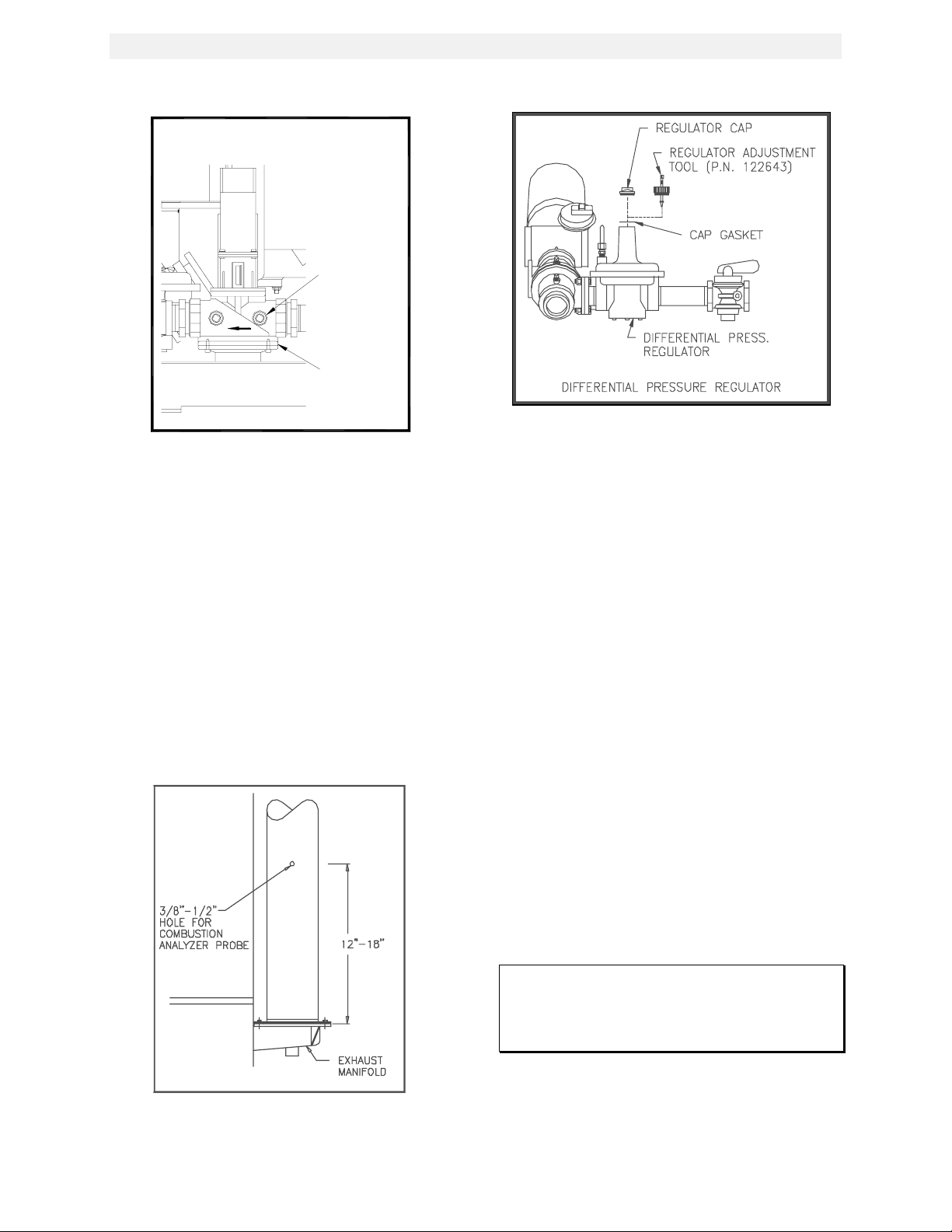
4.2.2 PREPARING THE FLUE VENT
PROBE HOLE
1. If the unit has been installed using the
recommended AL29-4C vent, there will be a
3/8” hole, 18” to 24” above the exhaust
manifold. The outer vent section, that
covers vent section connections must be
loosened and slid down to uncover the hole
(see Fig. 4.2).
2. If equipped with one, adjust the stop on the
combustion analyzer probe so that it
extends into the flue gas flow without hitting
the opposite wall of the flue. Do not insert
the probe at this time.
INITIAL START-UP
Figure 4.3
Differential Reg ulator Adjustment Tool
Installation
4.2.3 INSTALLING THE DIFFERENTIAL
REGULATOR ADJUSTMENT TOOL
1. Remove the cap from the differential
pressure regulator (see Fig. 4.3).
2. Place the gasket from the regulator cap onto
the regulator adjustment tool.
3. Prior to Installing the tools on the regulator
pull up the tool's screwdriver blade. Then
thread the tool into the regulator.
4. Engage the tool’s screwdriver blade into the
regulator’s adjustment screw slot.
4.3 COMBUSTION CALIBRATION
The KC-1000 ships combustion calibrated from
the factory. Recalibration as part of a start-up is
necessary due to altitude, gas BTU content, gas
supply piping and supply regulators. Factory test
data sheets are shipped with each unit as a
reference.
Figure 4.2
Analyzer Probe Hole Location
The following combustion calibration procedure
closely follows the factory procedure. By
following this procedure readjustment of
combustion will be kept to a minimum.
NOTE:
If the instructions in section 4. 2 have not yet
been performed, go back and do so before
continuing.
1. Open the supply and return valves to the unit
and ensure that the system pumps are
running.
2. Open the gas supply valve(s) to the unit.
18
Page 24
INITIAL START-UP
3. Using the 16” manometer installed as per
Section 4.2.1, adjust the gas supply
regulator until a reading of 12” W.C. static
pressure is obtained.
4. Place the green ON/OFF switch in the OFF
position. Turn on AC power to the unit. The
temperature controller and annunciator
displays should light.
5. Put the temperature controller in manual
mode
NOTE:
For a review of control panel operating
procedures, see Section 3.
6. Change the firing rate (Pct) to 0.0%.
7. Place the green ON/OFF switch in the ON
position.
8. Change the firing rate (Pct) to 25%. This will
put the unit into the starting sequence.
NOTE:
On initial start-up or return to service from a
fault condition, a warm-up timer of 2
minutes is activated by the controller. This
prevents the BTU input from exceeding
400,000 BTUs/HR even though the control
signal may indicate a greater input.
9. Observing the 2 minute warm-up period
increase the firing rate in 10 % increments
while monitoring the gas pressure after
every increase. If gas pressure dips below
8.5” W.C. for FM gas trains and 8.9” W.C.
for IRI gas trains at any input percentage,
stop and raise the pressure. Once 100% is
reached adjust the gas pressure for 8.5”
W.C. for FM and 8.9” W.C. for IRI.
NOTE:
If 8.5” W.C. (FM) or 8.9” (IRI ) gas pressure
cannot be obtained at the 100% firing rate,
it will be necessary to stop calibration and
contact the local AERCO representative in
your area. Running the unit on insufficient
gas pressure will void the warranty
10. Once 8.5” W.C. is set at the 100% level,
change the firing rate (Pct) to 30%. Insert
the combustion analyzer probe into the
stack.
NOTE:
Always go to a percentage of firing rate
from the same direction, ( i. e. , 100% to 30%
or 30% to 20%). Whenever going to a firing
rate from below (i.e., 20% to 30%), first go
above then back down to the desired firing
rate. This is necessary due to hysteresis in
the air/fuel stepper mot or. Hysteresis
causes the air/fuel valve to stop in a slightly
different position if the firing rat e
percentage is approached from below or
above. This results in a difference in
oxygen readings for the same f iring rate
percentage causing unnecessary
recalibration.
11. Allow enough time for the combustion
analyzer to settle. Compare the measured
oxygen level to the oxygen range for intake
air temperature in Table 1.
Table 1
Inlet Air
Temp Oxygen
20oF 5.7% <50ppm
40oF 5.5% <50ppm
60oF 5.2% <50ppm
80oF 5.0% <50ppm
100oF 4.9% <50ppm
Combustion Oxygen Levels for a 30%
Firing Rate
12. If the measured oxygen level is within the
range, at the current intake air temperature
in Table 1, no adjustment is necessary.
Proceed to step 17.
13. If the measured oxygen level is below the
range in Table 1, rotate the differential
regulator adjustment tool counter clockwise
1/4-1/2 revolution to decrease gas flow.
14. Wait for the combustion analyzer to settle,
then compare the new oxygen reading to
Table 1. Repeat adjustment until oxygen is
within the specified range.
15. If the measured oxygen level is above the
oxygen range in Table 1, rotate the
differential regulator adjustment tool
Carbon
Monoxide
19
Page 25
INITIAL START-UP
clockwise, 1/4-1/2 turns, to increase gas
flow.
16. Wait for the analyzer reading to settle, then
compare the new reading to Table 1. Repeat
adjustment until oxygen is within the
specified range.
NOTE:
Adjust only the different ial regulator at 30%
control signal, do not adjust the air shutter
17. Once the oxygen level is within the specified
range at 30%, change the firing rate to 20%.
18. Oxygen levels at the 16% firing rate should be
10% or less as shown in Table 2. If the
measured oxygen level is less then 10%, no
adjustment is necessary. If the measured
oxygen levels are greater than 10%, rotate the
regulator adjustment tool clockwise 1/4 to 1/2
revolution to add gas.
19. Wait for the analyzer to settle. Repeat
adjustment until the measured oxygen reading
is 10% or less.
20. If the oxygen level cannot be brought to 10%
or less, check the oxygen level in 1%
increments above the 16% firing rate until an
oxygen level of 10%, or less, is measured.
Reset the unit’ stop level at that firing rate. Go
back and recheck the oxygen level at 30%
before continuing.
Table 2
Inlet Air
Temp
20oF 10% or less <25ppm
40oF 10% or less <25ppm
60oF 10% or less <25ppm
80oF 10% or less <25ppm
100oF 10% or less <25ppm
Combustion Oxygen Levels for a 20%
21. Change the firing rate to 100%. After the
combustion analyzer has settled, compare
the measured oxygen level with the levels in
Table 3.
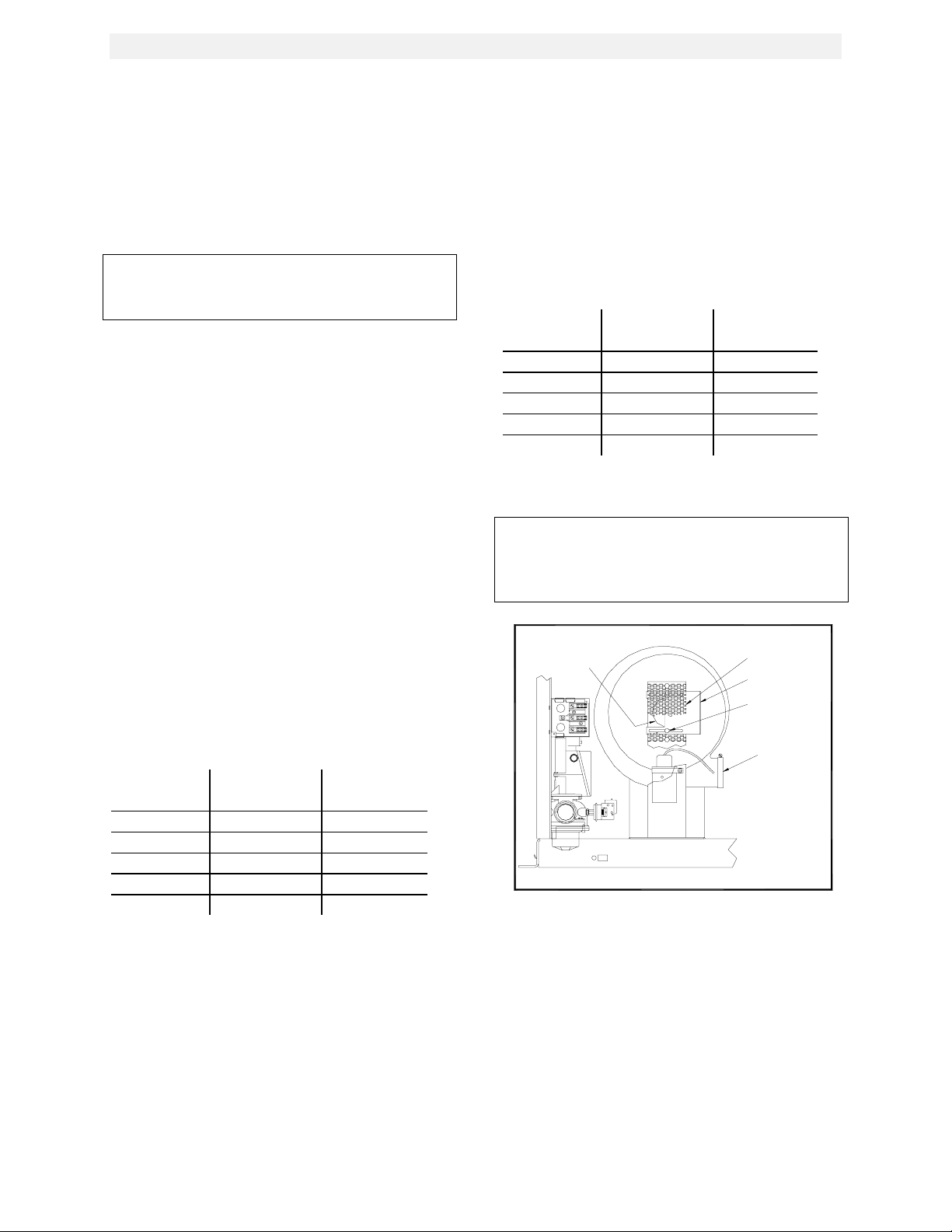
22. If the measured oxygen reading is below the
oxygen range in Table 3, loosen the two
bolts that secure the inlet air shutter to the
unit using a 7/16” wrench (see Fig. 4.4).
Oxygen Carbon
Monoxide
Firing Rate
Open the shutter 1/4” to 1/2”, to increase the
oxygen level then tighten the nuts.
23. Wait for the analyzer to settle, then compare
the new oxygen reading to Table 3. Repeat
the inlet air shutter adjustment until the
oxygen is within the specified range. Firmly
tighten the inlet air shutter locking nuts when
finished.
Table 3
Inlet Air
Temp
Oxygen Carbon
Monoxide
20oF 5.4% <150ppm
40oF 5.4% <150ppm
60oF 5.2% <150ppm
80oF 4.9% <150ppm
100oF 4.7% <150ppm
Combustion Oxygen Levels for a 100%
Firing Rate
REMINDER:
At 30% firing rate adjust only the differential
pressure regulator. At 100% firing rate,
adjust only the inlet air shutter.
BLOWER INLET
Figure 4.4
Air Shutter Locking Nut Locat ion
24. If the measured oxygen reading is above the
oxygen range in Table 3, loosen the two
7/16" locking nuts securing the inlet air
shutter. Close the air shutter 1/4” to 1/2” to
decrease the oxygen level and tighten the
two nuts.
25. Allow the analyzer to settle, then compare
the new oxygen reading to Table 3.
SCREEN
SHUTTER
SHUTTER LOCKING
NUTS
BLOWER OUTLET
20
Page 26
INITIAL START-UP
26. Allow the analyzer to settle. Repeat the
adjustment until the oxygen is within the
specified range. Firmly tighten the inlet air
shutter locking nuts when finished.
NOTE:
Adjust the inlet air shutter only at 100%
firing rate. Do not adj ust the differential
pressure regulator.
27. Change the firing rate to 30%. Allow time for
the combustion analyzer to settle. Check the
measured oxygen reading to insure that it is
still within the range as per Table 1.
28. Continue this procedure until all oxygen
levels are within the ranges specified in
Tables 1,2, and 3.
29. Record all readings on the AERCO start-up
sheet provided with each unit. Proceed to
Section 4.5.
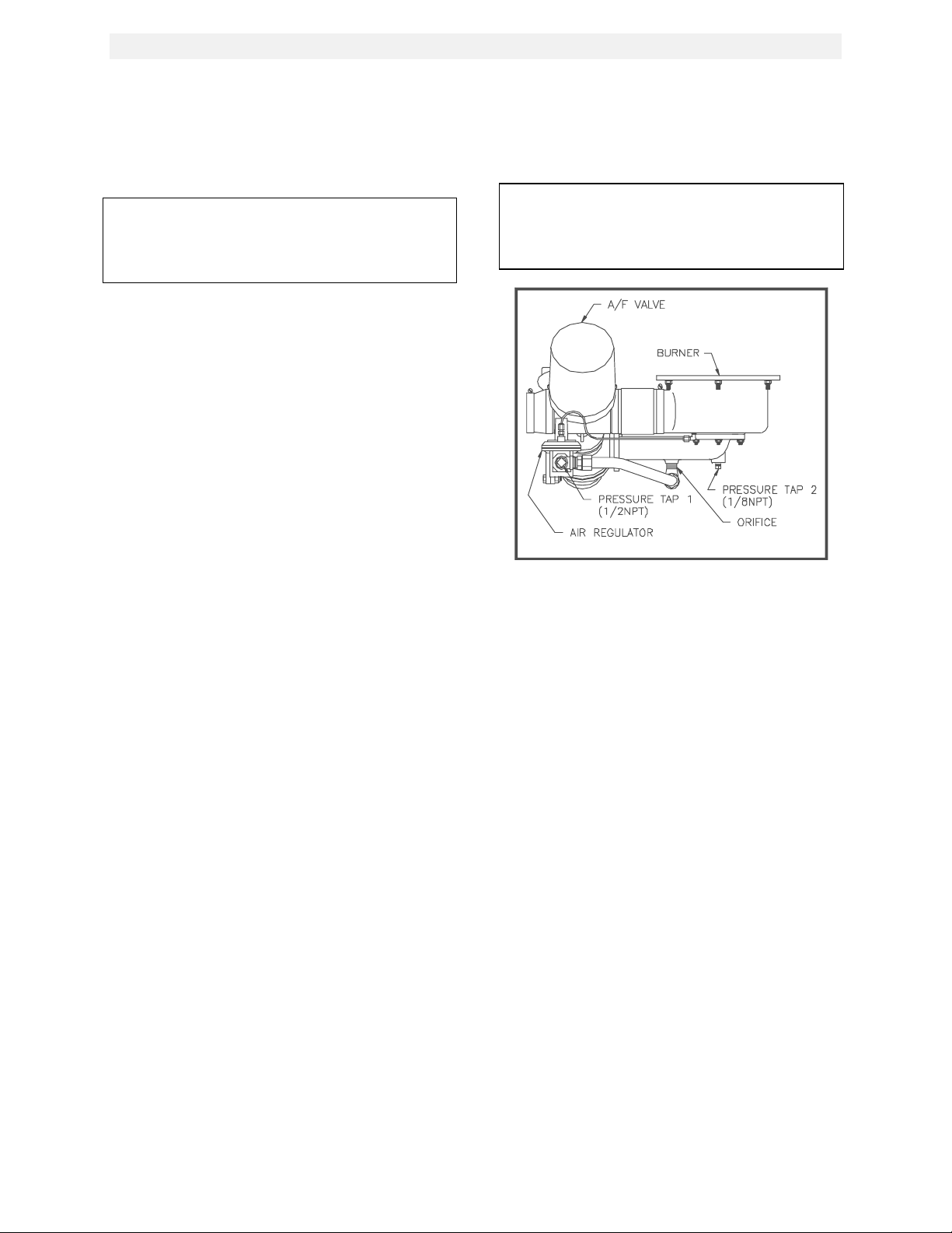
4.4 PROPANE COMBUSTION
CALIBRATION
For propane units it will be necessary to install
an additional 8” W.C. manometer as described
below. This is used to measure the pressure
drop across the air/propane mixing orifice.
1. Referring to Fig. 4.5 remove the 1/8” NPT
plug from the gas inlet pipe ahead of the
burner and install an 1/8” NPT barbed fitting.
2. Remove the 1/2” NPT plug from the tee
located after the air pressure regulator and
install a 1/2” barbed fitting (see fig. 4.5).
3. Attach the 8” W.C. manometer to the barbed
fittings installed in steps 1, and 2.
4. While following the combustion calibration
procedure in Section 4.3 measure the
pressure drop across the air/propane mixing
orifice using the 0-8” W.C. manometer.
5. This reading should remain a constant 3.8”
to 4” W.C. throughout the operating range.
6. If the pressure drop is not within this range,
remove the cap from the air pressure
regulator.
7. Using a flat blade screwdriver adjust the
regulator until 3.8”-4.0” W.C. is obtained.
Clockwise will increase the reading and
counter-clockwise will decrease the reading.
8. If adjustments are made to this regulator it
will be necessary to recheck oxygen settings
at 16%, 30%, and 100% firing rates
NOTE:
After an adjustment is m ade to the air
regulator, the cap must be put back on
securely to obtain an accurate reading
Figure 4.5
Propane Air Different ial Pressure Taps
4.5 UNIT REASSEMBLY
Once combustion calibration is set properly, the
unit can be re-assembled for permanent
operation.
1. Put the green ON/OFF switch in the off
position. Disconnect the AC power supply to
the unit.
2. Shut off the gas supply to the unit.
3. Remove the regulator adjustment tool by
first pulling up the screwdriver blade to
disengage it from the regulator adjusting
screw, and then turning the tool out of the
top of the regulator.
4. Remove the gasket from the tool and place it
back onto the regulator cap.
5. Apply a drop of silicone to the regulator
adjusting screw to lock its setting.
6. Reinstall the cap and gasket back on the
regulator. Tighten the cap using a
screwdriver or wrench.
7. Remove all of the manometers and barbed
fittings and reinstall the pipe plugs using a
suitable thread compound.
21
Page 27

INITIAL START-UP
8. Replace the unit’s panels and hood.
9. Remove the combustion analyzer probe
from the vent hole. Seal the probe hole and
replace the vent connection cover.
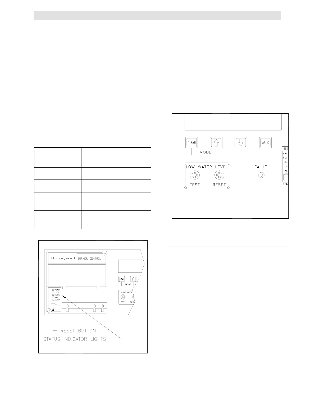
4.6 TEMPERATURE CONTROL
CALIBRATION
Although the unit comes factory set and
calibrated for a 130
necessary to recalibrate temperature control.
There are two main adjustments for performing
temperature calibration. These are OfSt (offset),
and SENS (sensitivity).
Adjustments to OfSt and SENS are made at
minimum and maximum load conditions and
should be made in increments of 1 to 3. After
making an adjustment, outlet water temperature
must be allowed to settle for several minutes
prior to making further adjustments.
When calibrating temperature control observe
the following:
A) The unit must be in operation and in AUTO
mode.
B) Use the outlet temperature and percent input
displays to set load conditions and see the
effect of adjustments.
C) Perform the calibration in the SECONDARY
menu of the temperature controller.
D) Make small adjustments and allow time
between adjustments for the outlet
temperature to stabilize.
E) Maintain water flow as constant as possible
during these adjustments.
F) Ensure that recirculation loops are operational
while the calibration is being performed.
0
F setpoint it is usually
4.6.1 SETTING TH E OUTLET WATER
TEMPERATURE SETPOINT
The setpoint of the unit may be changed by
following the procedure below. Once a setpoint
has been changed recalibration may be
necessary. The temperature calibration
procedure is outlined in step Sections 4.6.2 and
4.6.3
1. Enter the SECONDARY menu of the
temperature controller by simultaneously
!
pressing
2. Press INDEX until SEtP is displayed. This is
the unit’s desired outlet temperature.
and ENTER.
4.6.2 MINIMUM LOAD ADJUSTMENT
1. Place the control in the secondary menu by
!
simultaneously pressing
2. Press INDEX until Pct is displayed. This is
the unit’s percentage of firing rate.
3. Create a minimum load on the system that
will yield a steady percentage of firing rate
between 25% to 35%.
and ENTER.
NOTE:
It may be desirable to shut off the outlet
valve and use the hose bib to simulate a
minimum flow load condition.
4. Press the INDEX button until tout appears in
the lower display. The upper display will be
indicating the outlet water temperature.
5. Wait a few minutes to allow the outlet
temperature to stabilize.
NOTE:
Keep toggling between the outlet
temperature and input percentage to ensure
that both have stabilized.
6. Once stabilized the outlet temperature
should be 2 to 3 degrees above the unit’s set
point. If it does not stabilize to 2 or 3 degrees
above the setpoint, Offset (OfSt) must be
adjusted.
7. To adjust OfSt press INDEX until OfSt
appears in the lower display (see figure 4.6).
8. Raise or lower OfSt as needed using the
!&"
buttons. Increasing this value will
increase water temperature, decreasing it
will decrease water temperature.
9. Press ENTER to accept new values and
allow time for the system to settle between
adjustments.
3. Adjust this value to the desired set point
! "
using
value.
then press ENTER to accept the
FIigure 4.6
Secondary Menu Displaying Offset
22
Page 28

INITIAL START-UP
4.6.3 MAXIMUM LOAD ADJUSTM ENT
1. Enter the SECONDARY menu of the
temperature controller by simultaneously
pressing
2. Press INDEX until Pct is displayed. This is
the unit’s percentage of firing rate.
3. Create a maximum load on the system that
will yield a steady percentage of firing rate
between 80% to 90%.
!
and ENTER.
NOTE:
It may be necessary to open the outlet valve
if it was closed during minimum load
adjustment to obtain a sufficient flow rate for
maximum adjustment.
4. Press the INDEX button until tout appears in
the lower display. The upper display will be
indicating the outlet water temperature.
5. Wait a few minutes to allow the outlet
temperature to stabilize.
6. Once stabilized the outlet temperature should
be 2 to 3 degrees below the set point
temperature. If it does not stabilize to 2 to 3
degrees then the Sensitivity (SEnS) must be
adjusted.
7. To adjust the SEnS press INDEX until SEnS
appears in the lower display (see figure 4.7).
8. Raise or lower this value as needed using the
!,"
arrow keys. Increasing this value will
increase water temperature, decreasing it will
decrease water temp
9. Press ENTER to accept the new value. Allow
time for the system to settle between
adjustments.
10. If the outlet temperature holds setpoint
temperature stable, and within the +/_ 4
no further control adjustment is required.
11. If the outlet temperature does not maintain
setpoint after a reasonable amount of time
and adjustment contact your local AERCO
representative.
0
F,
Figure 4.8
Over Temperature Limit Switch Location
Figure 4.7
Secondary Menu Displaying Sensitivity
4.7 OVER TEMPERATURE LIMIT SWITCH
ADJUSTMENTS
There are two over-temperature limit switches
that will turn off the unit when the outlet water
temperature becomes too hot. The lower overtemperature limit switch is adjustable and should
be adjusted to 20
temperature the system will see. The upper overtemperature limit switch is a locked manual nonadjustable reset device. It will trip the unit off at
o
F above the highest operating
23
Page 29

200o F water temperature. Do NOT attempt to
adjust it’s set point.
To adjust the lower over temperature switch limit
switch:
1. Remove the wing nut from the top center of
the shell cap. Lift the cap off the shell.
2. The two over-temperature limit switches are
located at the top of the shell (see Fig. 4.8).
Do not adjust the upper switch. It has been
factory preset. Adjust the lower switch 20
higher than the unit’s set point.
3. Replace the shell cap and wing nut.
o
F
INITIAL START-UP
24
Page 30

SECTION 5-SAFETY DEVICE TESTING PROCEDURES
5.1 TESTING OF SAFETY DEVICES
Periodic testing of all controls and safety devices
is required to insure that they are operating as
designed. Precautions must be taken while tests
are being performed to protect against bodily
injury and property damage.
Systematic and thorough testing of the operating
and safety controls should be performed on a
scheduled basis, or whenever a control
component has been serviced or replaced. All
testing must conform to local jurisdictions or
codes such as ASME CSD-1.
NOTE:
MANUAL and AUTO modes are required to
perform the following tests. For a complete
explanation of these modes, see Section 3.
SAFETY DEVICE TESTING
1/4" NPT PLUG
(INSTALL
MANOMETER
HERE)
SSOV
NOTE:
It will be necessary to remove the sheet
metal covers and cap from the unit t o
perform the following test s.
WARNING!
THIS IS A 120 VOLT AC COMBUSTION
SAFEGUARD SYSTEM. POWER MUST
BE REMOVED PRIOR TO PERFORMING
WIRE REMOVAL OR OTHER TESTING
PROCEDURES THAT CAN RESULT IN
ELECTRICAL SHOCK.
5.2 GAS PRESSURE FAULT TEST
1. Shut off the gas supply to the unit.
2. Install an 0-16” W.C. manometer in the gas
pipe assembly below the low gas pressure
switch. (See Fig. 5.1)
3. Open the gas supply to the unit.
4. Start the unit.
5. Slowly close the manual gas supply valve
while monitoring the gas pressure. The unit
should fault and shutdown on “LOW GAS
PRESSURE” when the manometer indicates
approximately 7” W.C.
6. Open the gas supply to the unit.
7. The unit should start upon restoration of gas
pressure.
Figure 5.1
1/8” Pipe Plug Position for Manometer
installation
NOTE:
After faulting the unit, the fault me ssage will
be displayed and the fault indicator light will
flash until the CLEAR button is pressed.
5.3 LOW WATER LEVEL FAULT TEST
1. Place the ON/OFF switch in the OFF
position.
2. Close shut-off valves in the supply and
return piping to the unit.
3. Open the drain valve on the unit.
4. Allow air-flow into the unit by either opening
the relief valve or by removing the 1/4” plug
in the top of the unit.
5. The LOW WATER LEVEL message will be
displayed and the fault LED will flash after
the water level has gone below the level of
the probe.
6. The ON-OFF switch should not illuminate
when placed in the ON position and the unit
should not start.
7. Close the drain and pressure relief valve or
reinstall the plug in the top of the unit if
removed.
8. Open the water shut-off valve in the return
piping to the unit to fill the shell.
25
Page 31

9. Open the water shut-off valve in the supply
piping to the unit.
10. Press the LOW WATER LEVEL RESET
button to reset the low water cutoff and
press the CLEAR button to reset the
annunciator and LCD displays once the shell
is full.
11. Place the ON-OFF switch in the ON position.
The unit is now ready for operation.
5.4 WATER TEMPERATURE FAULT
TEST
1. In AUTO mode, allow the unit to stabilize at
its setpoint.
2. Lower the operating temperature limit switch
setting to match the outlet water
temperature. (See Fig. 5.2).
SAFETY DEVICE TESTING
2. Once the unit is firing, close the manual
leak-detection valve. This is the valve
located between the safety shut off valve
and the differential gas pressure regulator
(See Fig. 5.3).
3. The unit should shut down within 1-2
seconds and indicate a LOCKOUT RUN
FLAME fault on the LCD display.
4. Leaving the manual leak detection valve
closed, reset the combustion safeguard and
CLEAR the annunciator
5. Restart the unit.
6. The unit should lockout and display
LOCKOUT START FLAME during ignition.
7. Open the leak detection valve.
Figure 5.2
Temperature Limit Switch Setting
3. Once the limit switch setting is approximately
at the actual water temperature indicated by
tout, the unit should shutdown. The fault light
should be flashing and the message “HIGH
WATER TEMP” should be displayed. The
ON/OFF switch should not be illuminated
and the unit should not start.
4. Reset the temperature limit switch setting to
a minimum of 20
temperature.
5. The unit should start once the temperature
limit switch setting is above the actual outlet
water temperature.
o
F above the set point
5.5 FLAME FAULT TEST
1. Start the unit.
Figure 5.3
Manual Leak Detection Valve
9. Reset the Combustion safeguard and
CLEAR the annunciator.
10. Start the unit.
5.6 AIR PRESSURE FAULT TEST
WARNING!
THIS IS A 120 VOLT AC COMBUSTION
SAFEGUARD SYSTEM. POWER MUST
BE REMOVED PRIOR TO PERFORMING
WIRE REMOVAL, OR TESTING
PROCEDURES THAT CAN RESULT IN
ELECTRICAL SHOCK.
1. Disconnect AC power from the unit.
26
Page 32

SAFETY DEVICE TESTING
2. Disconnect wire #17 from the air pressure
switch located on the air/fuel valve (See Fig.
5.4).
3. Restore AC power to the unit.
4. Produce a “call for heat” to start the unit.
The unit should fault and display the
message SYSTEM FAULT AIR FLOW
SWITCH.
Figure 5.4
Blower Proof Switch Location and Wiring
6. Clear the annunciator. Turn the ON/OFF
switch to the OFF position.
SSOV ACTUATOR
COVER
SSOV ACTUATOR
COVER SCREW
Figure 5.5
SSOV Actuator Set Screw Location
5. Disconnect AC power to the unit.
6. Remove the air/fuel valve cover by loosening
the 3 screws securing it in place. (See Fig.
5.6).
5. Disconnect AC power from the unit.
6. Replace wire #17
7. Restore AC power to the unit.
8. Reset the combustion safeguard and clear
the annunciator display.
5.7 PURGE INTERLOCKS FAULT TEST
1. Turn the ON/OFF switch to the OFF
position.
2. Loosen the two set screws that attach the
safety shut off valve actuator to its valve
body. (See Fig. 5.5).
3. Lift the SSOV Actuator clear of the valve
body. This will open the proof of closure
switch.
4. Start the unit in manual mode
5. The unit should shutdown and display the
message SYSTEM FAULT PURGE
INTERLOCKS.
Figure 5.6
Air/Fuel Valve Cover Screw Locations
9. Disconnect wire #60 from the air/fuel valve
open position switch. This is the switch
closest to the blower (See Fig. 5.7).
27
Page 33

SAFETY DEVICE TESTING
10. Restore AC power to the unit.
11. Start the unit.
WARNING!
THIS IS A 120 VOLT AC COMBUSTION
SAFEGUARD SYSTEM. POWER MUST
BE REMOVED PRIOR TO PERFORMING
WIRE REMOVAL, OR OTHER TESTING
PROCEDURES THAT CAN RESULT IN
ELECTRICAL SHOCK.
20. Reconnect wire #62 to the ignition position
switch
21. Replace the air/fuel valve cover.
22. Restore AC power to the unit
23. Set the unit to auto mode to resume normal
operation.
5.8 SAFETY PRESSURE RELIEF VALVE
TEST
Test the safety Pressure/Temperature Relief
Valve in accordance with ASME Boiler and
Pressure Vessel Code, Section VI.
Figure 5.7
Air/Fuel Valve Open Position Switch
Location
12. The unit should shutdown and display the
message SYSTEM FAULT PURGE
INTERLOCKS.
13. Disconnect AC power from the unit.
14. Reconnect wire #60 to the air/fuel valve
open position switch.
15. Disconnect wire #62 from the ignition
position switch. This is the switch closest to
the burner of the unit (See Fig. 5.7).
16. Restore AC power to the unit, and reset the
combustion safeguard.
17. Start the unit.
18. The unit should lockout and display the
message LOCKOUT START FLAME
19. Disconnect AC power from the unit
28
Page 34

SECTION 6 – MAINTENANCE
MAINTENANCE
6.1 MAINTENANCE SCHEDULE
The KC1000 requires regular routine
maintenance to keep up efficiency and
reliability. For best operation and life of the unit,
the following routine maintenance procedures
must be performed in the specified timeperiods.
WARNING!
TO AVOID PERSONAL INJURY, BEFORE
SERVICING:
(A) DISCONNECT AC POWERTO THE
UNIT
(B) SHUT OFF THE GAS SUPPLY TO THE
UNIT
(C) ALLOW THE UNIT TO COOL TO A
SAFE TEMPERATURE
6.2 SPARK IGNITOR
The spark ignitor assembly is located in the body
of the burner (see Fig. 6.1). The ignitor may be
HOT. Care should be exercised. It is easier to
remove the ignitor from the unit after the unit has
cooled to room temperature.
CAUTION!
The ignitor must be rem oved and installed
using the ignitor remo val tool pr ovided with
the unit(s). Damage to t he bur ner due to
using a socket for r em oval and installat ion
of the ignitor is not covered under warranty
To inspect/replace the Ignitor
1. Put the green ON/OFF button on the control
panel, to the OFF position and disconnect
AC power to the unit. Disconnect the plastic
tubing from the condensate cup to drain and
remove the rear cover panels from the unit.
Access to the spark ignitor may also be
gained by removing the unit’s right side
panel
2. Disconnect the ignitor cable from the ignitor
contactor and unscrew the ignitor contactor
from the burner shell.
3. Insert the ignitor removal tool into the burner
shell, where the ignitor contactor was
removed. Screw the outer barrel of the tool
into the burner shell. Push the inner barrel
up and fit the hexagonal end of the tool over
the ignitor. Unscrew the ignitor from the
burner head and then the tool from the
burner shell.
4. The ignitor is gapped at 1/8-inch. If there is
substantial erosion of the spark gap or
ground electrode, the ignitor should be
replaced. If carbon build-up is present, clean
the ignitor using fine emery cloth. Repeated
carbon build-up on the ignitor is an indication
that a check of the combustion settings is
required, (see Sections 4.2 and 4.3 for
Combustion Calibration)
.
Table 1 Maintenance Schedule
Section Item 6 Mos. 12 Mos. 24 Mos. Labor Time
6.2 SparkIgnitor Inspect Replace 15 mins.
6.3 Flame Detector Inspect Replace 15 mins.
6.4
6.5
Combustion
Adjustments.
Testing of
Safety Controls
Check Check 1 hr.
Test 20 mins.
BTU
6.6
Transmittert.
Oil 15 mins.
Pump
6.7
6.8
BTU
Transmitter
*Manifold &
Tubes
Inspect & clean if
necessary
Inspect & clean if
necessary
50 mins.
4 hrs.
6.9 Heat Exchanger Inspect 1. 5 hr s.
* Recommended only when unit will be run in an extrem e condensing mode for prolonged
periods of time.
29
Page 35

5 Prior to reinstalling the ignitor, an anti-seize
compound must be applied to the ignitor
threads.
6 Reinstall the ignitor using the ignitor removal
tool. Do not over tighten the ignitor a slight
snugging up is sufficient. Reinstall the ignitor
contactor (hand tight only) and reconnect the
ignitor cable.
7. Replace the rear cover panels or right side
panel. Replace the condensate cup to drain
tubing.
6.3 FLAME DETECTOR
The flame detector assembly is located in the
body of the burner (see Fig. 6.1). The flame
detector may be HOT. Allow the unit to cool
sufficiently before removing the flame detector.
MAINTENANCE
6. Replace the rear cover panels or left side
panel. Replace the condensate cup to drain
tubing.
6.4 COMBUSTION CALIBRATION
Combustion settings must be checked at the
intervals shown in Table 1 as part of the
maintenance requirements. Refer to Sections
4.2 and 4.3 for combustion calibration
instructions.
6.5 SAFETY DEVICE TESTING
Systematic and thorough tests of the operating
and safety devices should be performed to
ensure that they are operating as designed.
Certain code requirements, such as ASME
CSD-1, require that these tests be performed on
a scheduled basis. Test schedules must
conform to local jurisdictions. The results of the
tests should be recorded in a log- book. See
Section 6-Safety Device Testing Procedures.
Figure 6.1
Spark Ignitor and Flame Det ector Location
To inspect or replace the flame detector:
1. Put the green ON/OFF button on the control
panel, to the OFF position and disconnect
AC power to the unit.
Disconnect the plastic tubing from the
2.
condensate cup to drain and remove the
rear covers from the unit.
6.6 BTU TRANSMITTER PUMP
LUBRICATION
The BTU Transmitter pump should be lubricated
every six months. There are two oil ports located
on the top of the pump, (see Fig. 6.2). Oil using
4 to 5 drops of SAE20 weight non-detergent oil
at each port. DO NOT OVER OIL.
Disconnect the flame detector lead wire.and
3.
unscrew the flame detector and remove it
from its guide tube.
4. Inspect the detector thoroughly. If eroded,
the detector should be replaced. Otherwise
clean the detector with a fine emery cloth.
5. Reinstall the flame detector hand tight only,
and reconnect the flame detector lead wire.
Figure 6.2
BTU Transmitter Pump Oil Hole Location
30
Page 36

MAINTENANCE
6.7 BTU TRANSMITTER ASSEMBLY
The BTU Transmitter is a crucial part of the
unit’s temperature control system. It must be
inspected and kept free of scale and debris in
order for the unit to maintain accurate outlet
water temperatures.
To inspect the transmitter:
1. Place the ON\OFF switch in the OFF
position.
2. Remove the sheet metal covers from the
unit.
3. Shut the water inlet, outlet and recirculation
valves to the unit.
4. Open the drain valve on the unit.
5. Slowly open the pressure relief valve to allow
air-flow into the unit.
6. Drain the unit until the WATER LEVEL
FAULT LED is illuminated. Drain slightly
more, then release the relief valve and close
the drain valve on the unit.
7. Disconnect electrical power to the unit.
8. Close the 3 ball valves on the BTU
transmitter, (See Fig. 6.3).
NOTE:
It is not necessary to disconnect the
electrical wires to the pump
Figure 6.4
BTU Transmitter Pum p Disassem bly
10. Using a 5/8” and 9/16” wrench loosen the 4
compression fittings holding the lower tubing
assembly in place, (See Fig. 6.5)
Figure 6.3
Ball Valve Locations
9. Remove the 4 screws holding the BTU
transmitter pump to the impeller housing.
Remove and set the pump aside, (See Fig.
6.4).
Figure 6.5
Compression Fitting Locations
11. Carefully remove the lower tubing as sembly
taking care not to lose either the cold water
or hot water mixing orifice, (See Fig. 6.6).
31
Page 37

MAINTENANCE
12. Loosen the compression fitting holding the
hydraulic zero and control orifice tube
assembly to the pump’s impeller housing,
(See Fig. 6.6).
13. Remove the compression fitting at the top of
the impeller housing and remove the
impeller housing, (See Fig. 6.7).
Figure 6.8
BTU Transmitter Hot Water Tube
Disassembly
Figure 6.6
BTU Transmitter Disassem bly
NOTE:
The cold water orifice is slightly larger than the
mixing orifice. The orifice must be correctly
installed for proper temperature control.
Figure 6.7
BTU Transmitter Pum p Com p r ession Fitting
Locations
14. Remove the compression fitting securing the
pump outlet tube to the ball valve and
remove the pump outlet tube.
15. Remove the ball valve connected to the hot
water tube coming from the top of the shell
by loosening the compression fitting
securing it to the hot water tube, (See Fig.
6.8).
o
16. Loosen the 90
of the shell holding the hot water tube, (See
Fig. 6.9). Slide the hot water tube down
slightly but do not remove it from the unit.
Remove the 90
17. Inspect all fittings and tubing for blockage
due to scale or debris. Clean or replace as
necessary.
18. Inspect the mixing orifice for blockage or
degradation due to erosion, (See Fig. 6.6).
Clean or replace as necessary.
19. The pump impeller may be checked by
removing the 4 screws from the cover
encasing the impeller in the housing, (See
Fig. 6.10).
compression fitting at the top
o
fitting.
32
Page 38

Figure 6.9
BTU Transmitter Shell Com ponents
MAINTENANCE
NOTE:
Compression fittings are nickel-plated and
should be replaced only with nickel-plated
fittings. Do not use brass fittings
6.8 MANIFOLD AND EXHAUST TUBES
The presence of even trace amounts of
chlorides and/or sulfur, in the combustion air and
fuel sources, can lead to the formation of
deposits on the inside of the exchanger tubes,
the exhaust manifold, and/or the condensate
cup. The degree of deposition is influenced by
the extent of the condensing operation and the
chloride and sulfur levels that vary significantly
from application to application.
The following parts will be necessary for
reassembly after inspection:
GP-122537 Exhaust Manifold to
Combustion Chamber
Gasket
GP-18900 Manifold to Tubesheet
Gasket
GP-18899 Burner Gasket
GP-122551 Burner Release Gasket
GP-161151 Combustion Chamber Liner
.
Figure 6.10
Impeller Housing Disassembly
21 Once the BTU transmitter has been
inspected and cleaned, reassemble in the
reverse order.
NOTE:
Do not attempt to adjust the Hydraulic Zero
Needle Valve. This is a factory-preset item.
Refer to Figure 6.6.
To remove the manifold for inspection:
1. Disconnect AC power and turn off the gas
supply to the unit.
2. Remove the sheet metal covers from the
unit.
3. Disconnect the plastic tubing from the
condensate cup to drain and remove the
rear covers.
4. Remove the condensate cup from under the
unit and the condensate drainage tubing
from the manifold.
5. Disconnect the flame detector and ignition
cable wires from the flame detector and
ignitor contactor. Remove the flame detector
and ignitor as per sections 6.2, and 6.3.
6. Remove the grounding terminal from the
burner by loosening the upper screw and
sliding the connector from the grounding rod,
(See Fig. 6.11).
7. Using a 7/16” socket or open end wrench
remove the four 1/4”-20 nuts on the gas inlet
pipe flange at the burner, (See Fig. 6.12).
8. Using two 9/16” wrenches remove the 3/8"-
16 hex nuts and bolts on the gas inlet pipe
flange at the air/fuel valve, (see Fig. 6.12).
33
Page 39

Figure 6.11
Grounding Terminal Location
MAINTENANCE
9. Loosen the hose clamp at the air/fuel valve
outlet and slide the clamp back towards the
burner, (see Fig. 6.12).
10. Using a 1/2” socket wrench remove six 5/1618 hex nuts supporting the burner, (see Fig.
6.12).
Figure 6.13
Exhaust Sensor Connector Location
13. Disconnect the air/fuel valve wire harness,
the 12 pin connector, from the control panel.
14. Disconnect wires #24 and #17 from the
blower proof switch (See Fig. 6.14).
Figure 6.12
Burner Disassembly Diagram
11. Lower the burner while sliding the air hose
off the air/fuel valve. Remove the burner
through the rear of the unit.
12. Disconnect the exhaust temperature sensor
by unscrewing it from the exhaust manifold,
(See Fig. 6.13).
Figure 6.14
Blower Proof Switch Wir e Locations
15. Loosen the hose clamp on the air/fuel valve
inlet and slide the clamp back towards the
blower, (See Fig. 6.15).
34
Page 40

Figure 6.15
Air/Fuel Valve Inlet Hose Clamp
16. Using an 11/16” wrench, loosen the
compression fittings on the feedback tube
between the air/fuel valve and the differential
pressure regulator. Remove the feedback
tube, (See Fig. 6.16).
17. Using two 9/16” wrenches remove the two
3/8-16 hex nuts and bolts securing the
air/fuel valve to the differential pressure
regulator, (See Fig. 6.16).
MAINTENANCE
19. Remove the flue venting from the exhaust
manifold.
20. Removing the exhaust manifold insulation
will prevent it from being damaged and will
make it easier to handle the exhaust
manifold once it is removed. Using a 7/16”
wrench or socket remove the 3 bolts and
fender washers securing the insulation to the
exhaust manifold.
21. Loosen the three 1-1/16” nuts that hold the
manifold. Remove the two side nuts. DO
NOT REMOVE THE FRONT NUT, (See Fig.
6.17).
22. Carefully pull the manifold down and back,
removing it through the back of the unit.
23. Inspect the manifold and exhaust tubes for
debris. Clean out any debris as necessary.
24. Inspect the combustion chamber and the
combustion chamber liner. Replace the liner
if any signs of cracking or warpage are
evident.
NOTE:
Install the combustion chamber liner prior t o
reinstalling the exhaust manifold
18. Remove the air/fuel valve taking care not to
damage the flange “O” ring.
Figure 6.16
Feedback Tube and Air/Fuel Valve to
Differential Regulator Bolts
Figure 6.17
Manifold Nut and Bolt Locations
25. Replace the gasket between the manifold
and the combustion chamber (P/N GP-
35
Page 41

122537). The use of Permatex or a similar
gasket adhesive is recommended.
26. Replace the gasket between the manifold
and tubesheet (P/N GP-18900). Do not use
any gasket adhesive; this gasket has an
adhesive backing
27. Beginning with the manifold, reinstall all the
components in the reverse order that they
were removed.
6.8.1 PROPANE UNITS
For propane units it will be necessary to remove
the air mix assembly in addition to the steps
outlined in Section 6.8. Proceed as follows:
1. Follow steps 1 through 5 under Section 6.8
2. Using a wrench, loosen the two
compression fittings holding the 1/4”
feedback tube between the burner and air
regulator and remove the feedback tube.
(See Fig. 6.18)
3. Using a 1-1/16” wrench or an adjustable
wrench loosen and remove the 12” flexible
gas hose.
4. Proceed back to Section 6.8 and continue at
Step #6.
NOTE:
Older propane units have a 1/8” Feedback
Tube and 1/8” OD tube compression
fittings.
6.9 HEAT EXCHANGER INSPECTION
The water-side of the heating surfaces may be
inspected by removal of the top heater head.
(See Fig.’s 6.19 & 6.20) The following gaskets
will be needed prior to performing the inspection:
GP-18856 Release Gasket
GP-18532 Shell Gasket
MAINTENANCE
Figure 6.18
Propane Air Regulator Measuring Taps
6.9.1 FLAT (NEW) STYLE HEAD
To inspect the heat exchanger watersides:
1. Disconnect the electrical power to the unit.
2. Close the water inlet, outlet, and
recirculation shut-off valves to the unit.
3. Open the drain valve carefully while opening
the relief valve on the right side of the unit
shell to relieve pressure and allow air into
the shell.
CAUTION!
Do not drain the unit without venting the
shell! A vacuum in the unit may displace the
liner causing serious damage not covered
by warranty.
NOTE:
This manual covers two different st yle
heater heads. The newer is a flat head,
the older is a concave head.
4. Remove the wing nut from the top center of
the shell cap and remove the cap.
5. Remove the nuts and studs from the upper
head. Remove the upper head and upper
head-liner, (See Fig. 6.19).
6. Inspect and clean the heat exchanger tubes
of scale and all gasket surfaces thoroughly
before reassembling the upper head.
AERCO recommends that NEW gaskets be
used when reassembling.
36
Page 42

7. Place a shell head gasket on top of the shell
ring first, then place the release gasket on
top of the shell head gasket. Align the
gasket holes with those in the shell ring.
8. Place the upper head liner on top of the
gaskets.
9. Place the upper head on next aligning the
holes.
10. Reassemble the studs and nuts through the
upper head and shell ring. Cross tighten the
nuts to approximately 75 ft./lb. torque to
obtain a uniform seating, then progressively
tighten the nuts to 150 ft./lb.
11. Replace the unit Cap. Close the drain valve
and reopen the inlet, outlet, and recirculation
valves to refill the unit as per Section 2.8.1.
6.9.2 CONCAVE (OLD) STYLE HEADS
To inspect the heat exchanger watersides:
MAINTENANCE
1. Disconnect the electrical power to the unit.
2. Close the inlet, outlet and recirculation
shutoff valves to the unit.
3. Open the drain valve while carefully opening
the relief valve on the right side of the unit
shell to relieve pressure in the shell.
4 Remove the wing nut from the top center of
the shell cap and remove the cap.
CAUTION:
Do not drain the unit without venting the
shell! A vacuum in the unit may displace
the liner reulting in damage not covered
by warranty.
Figure 6.19
Flat Style Head Configuration
5. Remove the nuts and studs from the shell
ring and remove the upper head ring.
Remove the upper head and head liner,
(See Fig. 6.20).
6. Inspect and clean the heat exchanger
thoroughly before reassembling the upper
head.
7. Clean all gasket surfaces thoroughly.
AERCO recommends that NEW gaskets be
used when reassembling the upper head to
the unit shell.
37
Page 43

MAINTENANCE
Figure 6.20
Concave Style Head
8. Place the shell gasket then the release
gasket on top of the shell ring and align the
gasket holes with those in the flange.
9. Place the upper head liner (dimple facing
in/down) on top of the gasket, with all holes
aligned. Then place the upper head on the
upper head liner.
10. Place the upper head ring on top of the
upper head.
11. Reassemble the studs and nuts through the
upper head and shell ring. Cross tighten the
nuts to approximately 75 ft./lb, to obtain
uniform seating, and then progressively
tighten the nuts to 150 ft./lb.
38
Page 44

TROUBLESHOOTING
SECTION 7- TROUBLESHOOTING GUIDE
This troubleshooting section is intended to serve
as a guideline to determining and solving faults
on the unit. Whenever a fault occurs, proceed as
follows:
1. Determine the cause of the fault by following
the procedures within this section.
2. Once the cause has been determined, take
the proper actions to remedy the fault.
3. Start the unit in accordance with this manual.
In the event that a fault cannot be remedied,
contact your local AERCO Representative or the
factory for Technical Assistance.
WARNING!
ELECTRIC SHOCK HAZARDS EXIST
THAT CAN CAUSE SEVERE INJURY.
DISCONNECT POWER BEFORE
PERFORMING ANY MAINTENANCE
AND/OR SERVICING.
WARNING!
NEVER JUMPER (BY-PASS) ANY SAFETY
DEVICE. DAMAGE, OR PERSONAL
INJURY COULD RESULT. USE AN OHM
METER FOR CHECKING CONTINUITY
ON SAFETY DEVICES.
WARNING!
TROUBLESHOOTING PROCEDURES, AS
OUTLINED IN THIS SECTION, MUST BE
PERFORMED BY QUALIFIED SERVICE
PERSONNEL.
7.1 LOW GAS PRESSURE
The LOW GAS PRESSURE message indicates
that gas pressure has gone below 7” W.C.,
tripping the low gas pressure switch.
7.1.1 LOW SUPPLY GAS PRESSURE
7.1.2 GAS PRESSURE SWITCHES
Recommended Troubleshooting Equipment:
16” Manometer
Analog or Digital Ohmmeter
7.1.1 LOW SUPPLY GAS PRESSURE
1. Install a manometer in the unit manifold as
per Section 4.2.1
2. Check the static pressure to the unit. It
should be 10” to 12” W.C
3. If the static pressure to the unit is lower than
10” W.C., readjust the supply regulator until
it’s output is 10” to 12” W.C. If a static supply
pressure of 10” to 12” W.C. cannot be
obtained, proceed to Step 8.
4. If static pressure is already 10” to 12” W.C.
or you have readjusted the static supply
pressure, start the unit.
5. If gas pressure drops to below 7” W.C.
during the Ignition cycle, proceed to Step 8.
6. If gas pressure does not drop below 7” W.C.
in any one of the above steps slowly
increase the input percentage in steps of
10% while monitoring gas pressure.
7. If gas pressure drops below 7“ W.C. tripping
the gas pressure switch, proceed to step 8.
8. If gas pressure stays within the unit’s
specifications of 8.5” at maximum firing rate
and has a maximum static pressure of 14”
proceed to Section 7.1.2.
9. Check the gas pressure to the unit’s supply
regulator. It should be 14” W.C. or greater. If
the supply pressure is 14” W.C. or greater,
check the supply regulator and supply piping
for correct sizing.
.
7.1.2 GAS PRESSURE SWITCHES
1. If static pressure to the unit is correct,
disconnect electric power to the unit.
Remove wires #20 & #32 from the low gas
pressure switch.
2. Using an ohmmeter, check the gas pressure
switch for continuity.
supply to the unit is on.
3. Replace the switch if it does not show
continuity.
4. If the switch shows continuity, reconnect
wires #20 and #32 to the switch. Remove
the 15-pin connector from the control panel.
Be sure that the gas
39
Page 45

TROUBLESHOOTING
5. Referring to system schematic 161412 in
the Appendix, locate and check continuity in
wires #20 and #32 from the fifteen pin
connector through the switch and back to
the connector.
,
6. If there is no continuity
connectors at the switch end of the wires.
Check the pins in the 15-pin connector for
proper insertion or signs of wear.
7. If the 15-pin connector and the switch
connections are okay, reconnect the 15-pin
connector to the control panel. Restore
electric power.
If the gas pressure fault does not clear it will be
necessary to troubleshoot the control panel.
Contact a qualified service technician or your
local AERCO representative for more
information.
7.2 HIGH EXHAUST TEMPERATURE
A HI EXHAUST TEMP message indicates that
the exhaust temperature has exceeded 500
This fault only indicates on the display and
WILL NOT SHUT DOWN the unit. The fault
LED and the fault relay will trip indicating the
fault.
A high exhaust temperature is an indication that
the unit has a carbon coating on the fireside of
the heat exchanger exhaust tubes. This
condition results in a loss of heat transfer and
therefore high exhaust temperatures. Carbon
buildup can be due to due to improper
combustion calibration, a defective air or fuel
component, improper stop\start levels or
improper supply gas pressure. The unit should
be combustion calibrated to determine if one of
the above is responsible. Refer to section 4.4
for combustion calibration, or contact your local
AERCO representative further assistance.
check for loose
o
F.
2. Using an accurate temperature
measurement device, measure the actual
flue gas temperature. If the exhaust sensor
measurement is less than 500
pressing the clear button does not clear the
fault message, shut the unit off and remove
AC power from the unit.
3. Disconnect the exhaust sensor wires from
the field wiring box.
4. Check continuity between the sensor wires.
(ensure that the sensor has cooled below
400°). If there is continuity
exhaust sensor.
5. If there is no continuity and the exhaust
temperature fault will not clear, combustion
calibrate the unit as per Section 4.4.
o
F, and
,
replace the
7.3 LOW WATER LEVEL
A LOW WATER LEVEL message indicates that
water level in the unit is too low. Check that the
shutoff valves on the supply and return of the
unit are open and that there is water in the shell.
(Momentarily opening the relief valve and
looking for a strong flow of water will verify that
the unit shell has sufficient water level). If the
unit has water sufficient water level try to reset
the unit by pressing the low water level reset
button and the Annunciator clear button. If the
unit fires but the message will not clear, replace
the Annunciator. If the unit does not fire and the
message will not clear, check the following.
7.3.1 Water Level Probe
7.3.2 Wiring & Connections
7.3.3 Water level Circuit
Recommended Troubleshooting Equipment
• Digital Volt/Ohmmeter
7.2.1 Exhaust Temperature Sensor
7.2.2 Wiring & Connections
Recommended Troubleshooting Equipment
Digital Ohmmeter
Digital Temperature Meter
7.2.1 EXHAUST TEMPERATURE
SENSOR
1. Start the unit and wait for the HI EXHAUST
TEMP. message to display
7.3.1 WATER LEVEL PROBE
1. Disconnect the electric power to the unit.
2. Remove the unit cap and remove wire #25
from the water level probe.
3. Connect an AC voltmeter between wire #25
and the unit frame.
4. Reapply electrical power to the unit. The AC
voltmeter should read approximately 12
VAC. If approximately 12 VAC is not read on
the AC voltmeter, proceed to section 7.3.2.
40
Page 46

TROUBLESHOOTING
5. If 12 VAC is read on the AC voltmeter,
disconnect power to the unit and ground the
probe to the unit shell.
6. Restore electrical power to the unit. If the
fault does not clear, proceed to section
7.3.3. If the fault clears replace the probe.
7.3.2 WIRING AND CONNECTIONS
1. Disconnect electric power to the unit.
2. Disconnect wire #25 from the water level
probe and unplug the 9-pin connector from
the control box.
3. Referring to system schematic 161412 in the
Appendix, locate wire #25.
4. Using an ohmmeter check wire #25 for
continuity
5. If wire #25 does not have continuity, repair
as necessary.
6. If wire #25 has continuity, check the probe
end of the wire for a loose connector.
7. Check the pin in the 9-pin connector for
proper insertion or signs of wear.
8. If the connector and pin are okay, reconnect
wire #25 to the water level probe.
9. Restore the 9-pin connector to the control
panel.
10. Restore electric power to the unit. If the
water level fault does not clear, see Section
7.3.3.
7.3.3 WATER LEVEL CIRCUIT
1. Remove power from the unit.
2. Open the control panel to expose the wiring
and internal components.
WARNING!
This a 120 VAC system.
A shodk hazard exists.
3. Locate the low water level switch as shown
in Appendix E.
4. Remove wires #96 and #99 from terminals
LLCO and G.
,
5. Using an ohm meter
between wire #96 in the control box
wire # 25 on the unit. Also check continuity
between wire #99 in the control box and the
unit’s shell or frame.
check continuity
,
and
6. If there is no continuity repair as necessary.
If there is continuity, replace the low water
level circuit.
7.4 HIGH WATER TEMPERATURE
A HIGH WATER TEMPERATURE fault indicates
when the temperature of the discharge water
has exceeded the setpoint of the over
temperature switches.
First try to clear the fault message from the
Annunciator and start the unit. If the unit fires but
continues to display a HIGH WATER TEMP
message, replace the Annunciator. If the fault
message will not clear and the unit does not fire
check the following.
7.4.1 Determining the Cause
7.4.2 Over Temperature Limit Switches
7.4.3 BTU Transmitter Pump
7.4.4 Temperature Sensors
Recommended Troubleshooting Equipment
Digital Voltmeter
Digital Ohmmeter
7.4.1 DETERMINING THE CAUSE
Remove the unit cap to expose the over
temperature limit switches. Check the setpoint of
the unit and the setpoint of the lower over
temperature switch. The lower over temperature
switch must be set a minimum of 20
than the setpoint of the unit. Make adjustments if
necessary.
1. If the over temperature switch was correctly
set, 20°F above the unit setpoint, check that
the feedback is set to ON in the temperature
controller.
2. If the feedback was on, check that the 3 ball
valves on the BTU Transmitter are open.
3. Check that the BTU transmitter is running. If
the pump is not running, proceed to section
7.4.3.
4. If all the above are okay but the High Water
Temp fault persists, recalibrate the unit for
temperature control as per Section 4.7.
5. If the unit cannot be temperature calibrated,
The BTU transmitter must be checked for
scale or blockage as per Maintenance
Section 6.7.
6. If the BTU transmitter has no blockage or
scale, check the temperature sensor probes
as per Section 7.4.4.
o
F higher
41
Page 47

TROUBLESHOOTING
7. Reset the unit and if necessary, the upper
over-temperature limit switch. If the unit will
not reset proceed to section 7.4.2.
7.4.2. OVER TEMPERATURE LIMIT
SWITCHES
1. Disconnect electrical power to the unit.
2. Raise the temperature limit switch setpoint a
minimumof 10
water temperature.
3. Referring to system schematic 161412 in
Appendix F, remove wires #18 and #33 from
the lower switch and wires #19 and #33 from
the upper switch.
4. Using an ohmmeter, check for continuity
across the C, common, and NC, normally
closed, terminals of both switches.
5. Replace the switches if either or both show
no continuity
6. If the switches show continuity, disconnect
the 15-pin connector from the control panel.
7. Using an ohmmeter, check wires #18, #19
and #33 back to the 15-pin connector for
continuity.
8. Check for loose connectors on the switch
end of wires #18, #19 and #33.]
9. Check the pins of the 15-pin connector for
proper insertion or wear.
10. If the connectors, pins, and continuity are
okay, restore wires #19 and #33 to the lower
switch and wires #18 and #33 to the upper
temperature switch.
11. Restore the 15-pin connector to the control
panel.
12. Reapply electrical power to the unit.
13. If the over temperature fault does not clear
consult your local AERCO representative or
contact aqualified service technician.
0
F above the actual discharge
7.4.3 BTU TRANSMITTER PUMP
1. Disconnect electric power to the unit.
2. Referring to system schematic 161412 in
Appendix F, locate wires #10, #30, and #31.
3. Remove the wire nuts from wires #10 and
#31 and connect an AC voltmeter across
wires #10 and #31.
4. Restore electric power to the unit.
5. If there is 120 VAC across wires #10 and
#31, and the pump is not runing, replace the
pump.
6. If 120 VAC is not present across wires #10
and #31, disconnect electric power to the
unit.
7. Disconnect the 9-pin connector from the
control panel and remove the cover from the
unit’s AC wiring box.
8. Check for continuity in wires #10, #30 and
#31. Check for loose connections on wires
#30 and #31 located in the AC wiring box.
9. Check the pin in the 9-pin connector for
proper insertion or signs of wear.
10. If all wire connectors and pins are okay,
replace the control panel.
7.4.4. TEMPERATURE SENSORS
1. Close off the shutoff valves on the water inlet
and outlet lines of the unit. Close off any
recirculation lines to the unit.
2. Drain the unit while venting the shell, through
the relief valve, until a water level fault light
is observed.
3. Drain slightly more, then close the drain
valve.
4. Close off the three ball valves on the BTU
transmitter assembly.
5. Disconnect and remove the BTU transmitter
sensor.
6. Remove the unit cap. Disconnect and
remove the header sensor.
7. Allow the sensors to cool to ambient
temperature.
8. Referring to the Temperature Sensor Chart
in Appendix C of this manual, measure the
resistance of the probe and determine the
corresponding temperature from the chart.
9. Compare the reading with the ambient room
temperature. If there is a significant
discrepancy, greater than 10
erroneous sensor.
o
F, replace the
42
Page 48

TROUBLESHOOTING
10. Place the entire length of the sensors in a
water bath of known temperature. Measure
the resistance of the probe, and determine
the corresponding temperature from the
temperature sensor chart. If there is a
significant discrepancy, greater than 10°F
then replace the sensor.
11. Disconnect the 6 pin connector from the
control panel.
12. Referring to system schematic 161412 in
Appendix F, locate wires #1, #2, #3, #4 and
#5.
13. Check all wires for continuity and all
connectors for proper pin insertion and/or
worn pins. Repair as necessary.
14. If the sensors wiring and connectors are
okay. Place a 1000Ω ± 1% accuracy
resistor across the pins in the plugs that the
sensors were removed from.
NOTE:
The resistors must be placed across the
pins simultaneously to get accurate
readings.
NOTE:
If the sensors are removed and power is
applied to the unit the message bAd.I nP will
be displayed on the temperature control.
To clear this error press and hold the
INDEX and ENTER buttons simultaneously.
15. Reapply power to the unit.
16. Check the temperature control displays tout
in the primary menu and FFt in the
secondary menu. They should both read
70°F ± 10°F.
17. Place a 1.3 KΩ ± 1% resistor across the pins
in the plugs that the sensors were removed
from.
18. The temperature controller displays tout in
the Primary menu and FFt in the Secondary
menu should read 196° F ±10° F.
19. If the temperatures displayed are not within
tolerance the control should be replaced.
NOTE
If the display reads UFL or OFL or bAd InP,
this is an indication that the sensor wires
:
are shorted or in an open circuit condition,
which may indicate a wiring problem.
20. If the sensors wiring and connectors are
okay, reinstall the sensors.\
21. Reconnect the connectors to the sensors
and control panel, ensuring that they lock
firmly into place.
22. Refill the unit as per Section 2.8.1.
23. Restore electrical power to the unit.
7.5 LOCKOUT RUN FLAME
A LOCKOUT RUN FLAME message indicates
that the flame signal was lost after the unit
proved flame and was released to modulate. A
FLAME FAULT DURING IGN TRIAL message
indicates that flame was not recognized during
the ignition trial period.
7.5.1 Flame Fault While Firing
7.5.2 Flame Fault During Ignition Cycle
7.5.3 Safety Shut Off Valve
7.5.4 Spark Ignitor
7.5.5 Flame Detector
7.5.6 Ignition Circuit
7.5.7 Air Fuel Valve Ignition Position
witch
7.5.8 Flame Detector Voltage
7.5.9 Residual Flame
Recommended Troubleshooting Equipment
Digital or Analog Voltmeter
Combustion Analyzer
and 16” Manometers
7.5.1 FLAME FAULT WHILE FIRING
1. Install a DC voltmeter in the flame test jacks
located on the front of the combustion
safeguard. Start the unit in manual mode
2. Once flame is established, a steady reading
of approximately 5 VDC should be observed.
3. While in manual mode, fire the unit at
various firing rates (i.e., 16%, 30%, 50%,
100% etc.)
4. If flame signal is erratic at any time during
the test, combustion calibrate the unit as per
Section 4.this manual.
5. If combustion calibration is okay, remove the
burner and inspect it for debris that may
have fallen on it.
7.5.2 FLAME FAULT DURING IGNITION
TRIAL
1. Check that all gas supply valves are open
43
Page 49

TROUBLESHOOTING
2. If the gas supply valves were open, restart
the unit.
3. Remove the cover to the Air Fuel Valve.
Ensure that the Air Fuel Valve rotates to the
ignition position, and engages the ignition
position switch. If the air\fuel valve does not
,
rotate to the ignition position
Section 7.7.7.
4. If the air\fuel valve rotates and engages the
ignition position switch during the trial for
ignition, then visually watch/inspect the
safety shutoff valve, through the window on
the actuator half, to determine if it is
opening.
proceed to
NOTE:
At the ignition cycle, the low fire switch is
made, and the safety shutof f valve is
energized. The OPEN disk in the safety
shut-off valve actuator window should
slowly move downward indicating that the
valve is operating correctly. If the valve
does not open, proceed to Section 7.5.3
5. If the safety shutoff valve opens, check the
spark ignitor as per Section 7.5.4 and the
flame detector, as per Section 7.5.5.
6. If the spark ignitor and flame detector are
okay, or require replacement and the flame
fault persists, check the ignition circuit as per
Section 7.5.6.
7. If the flame fault persists after checking the
above, measure the flame detector lead
voltage as per Section 7.5.8.
8. If the flame fault persists, after checking the
above, remove the burner and inspect for
debris.’
9. If the flame fault persists after the above,
replace the combustion control.
7.5.3 SAFETY SHUTOFF VALVE
1. Start the unit.
2. When the starting sequence reaches the
Ignition trial cycle, observe the response of
the safety shutoff valve through the window
in the actuator portion
3. If the actuator does not open the valve,
disconnect electrical power to the unit.
4. Remove the actuator portion from the valve
body and inspect for signs of leaking
hydraulic fluid.
5. If the actuator is not leaking, set it back on
the valve body and remove the cover plate
exposing the control wiring.
6. Temporarily re-secure the actuator to the
valve body with the control wiring facing
outward for easy access.
7. Referring to system schematic 161412 in
Appendix F, connect an AC voltmeter across
wires #14 and #28.
8. Restore electrical power to the unit.
9. Start the unit.
10. At the ignition trial cycle 120 VAC should be
observed on the AC voltmeter.
11. If 120 VAC is observed on the voltmeter,
replace the safety shutoff valve actuator.
12. If 120 VAC is not observed on the AC
voltmeter, disconnect electrical power to the
unit.
13. Disconnect the 9-pin connector from the
control panel, and remove the cover from
the AC wiring box.
14. Referring to system schematic 161412 in
Appendix F, locate wire's #14, #28 and #27
and check each for continuity.
15. Check each wire for loose connectors at the
safety shut-off valve end. Check wires #28
and #27 for loose connectors in the KC1000
AC wiring box
16. Check the pin on wire #9 at the 9-pin
connector end, for proper insertion or wear.
17. If all wires show continuity and all
connections are okay, reconnect wire's #14,
#28 and #29 to the safety shutoff valve and
wires #28 and #29 to their proper locations
in the AC wiring box.
18. Replace the cover plates on the safety
shutoff valve actuator and the AC wiring box.
19. Reconnect the 9-pin connector to the control
panel ensuring that it locks into place.
44
Page 50

TROUBLESHOOTING
20. Restore electrical power to the unit and
restart the unit.
21. If the safety shutoff valve still does not open,
proceed to section 7.7.8.
22. Be sure to return the safety shutoff valve to
its original position and replace all cover
plates.
7.5.4 SPARK IGNITOR
1. Disconnect electrical power to the unit.
2. Remove the spark ignitor as per
Maintenance Section 6.3 of this manual.
3. Inspect the ignitor for signs of erosion.
4. Replace the ignitor if eroded.
Check for carbon buildup on the ignitor.
5. If there is carbon build-up on the ignitor, the
combustion calibration settings must be
checked as per Section 4. If the spark
ignitor is not eroded, it may be cleaned and
reused.
7.5.5 FLAME DETECTOR
1. Disconnect electrical power to the unit.
2. Remove the flame detector as per
Maintenance Section 6.3.
3. Check the detector for signs of erosion or
carbon buildup.
4. If the flame detector is eroded, replace it.
Otherwise, clean it using emery cloth.
5. Carbon buildup on the flame detector
indicates that unit may require combustion
calibration.
6. Check the combustion calibration settings as
per Start-Up Sections 4.3 and 4.4.
7.5.6 IGNITION CIRCUIT
1. Disconnect electrical power to the unit.
2. Close the manual-leak detection valve,
located between the safety shutoff valve and
the differential pressure regulator, on the
unit’s gas manifold.
3. Using either a spare ignitor, connect the
ignition cable directly to the ignitor.
4. Ground the ignitor to the frame of the unit.
5. Restore electrical power to the unit.
6. Start the unit.
7. At ignition, an arc should be observed. It
should last for approximately 15 seconds.
8. If there is no arc, disconnect electrical power
to the unit.
WARNING!
ELECTRIC SHOCK HAZARD. THE
SECONDARY OF THE IGNITION
TRANSFORMER HAS A POTENTIAL OF
6000 VOLTS. DO NOT HOLD OR TOUCH
ANY IGNITION CIRCUI T COMPONENTS
WHILE TESTING.
9. Remove the ignition cable and check it for
continuity or loose connections.
10. Replace the cable if there is no continuity. If
there is a loose connection, replace or repair
the cable as necessary.
11. If the ignition cable is okay, remove the
ignition transformer cover plate.
12. Referring to system schematic 161412 in
Appendix F, locate wires #12 and #29.
13. Connect an AC voltmeter across wires #12
and #29.
14. Restore electrical power to the unit and start
the unit.
15. At the ignition cycle check for 120 VAC
across wires #12 and #29.
16. If 120 VAC is observed across wires #12
and #29, replace the ignition transformer.
17. If 120 VAC is not observed on the AC
voltmeter during the Ignition cycle,
disconnect electrical power to the unit.
18. Disconnect the 9-pin connector from the
control panel, and wires #12 and #29 from
the ignition transformer.
19. Remove the cover plate from the AC wiring
box.
20. Referring to system schematic 161412 in the
Appendix, check wires #12 and #29 for
continuity.
45
Page 51

TROUBLESHOOTING
21. If wires #12 and #29 have continuity, inspect
the pin on wire #12 in the 9-pin connector for
proper insertion or signs of wear
22. Inspect the connector on wire #29 at the AC
wiring box end for a loose connection.
23. Make any necessary repairs.
24. Once all wiring and connections have been
inspected or repaired, reconnect wires #12
and #29 to the ignition transformer.
Reconnect wire #29 to its proper position in
the AC wiring box.
25. Reconnect the 9-pin connector to the control
panel ensuring it is locked into place.
26. Reinstall the cover plates on the ignition
transformer and the AC wiring box.
27. Be sure to reinstall the spark ignitor and
ignitor contactor if necessary and reconnect
the ignition cable to the ignition transformer
and the ignition contactor.
28. Reopen the leak detection valve.
29. Restore electrical power to the unit and start
the unit.
7. If 345 VAC is not observed, disconnect
electrical power to the unit.
8. Disconnect the 9-pin connector from the
control panel.
9. Referring to system schematic 161412 in
Appendix F, locate wire #9.
10. Check wire #9 for continuity
11. Check the flame detector end of wire #9 for
loose connections. Inspect the pins in the 9pin connector for proper insertion and signs
of wear.
12. Repair if necessary.
13. If wire #9 has continuity and all connections
are okay or a repair was performed,
reconnect the flame detector lead to the
flame detector. Reconnect the 9-pin
connector to the control panel.
14. Restore electrical power to the unit and
restart the unit.
15. If the flame fault persists, replace the
combustion control.
30. If the flame fault persists, replace the
Combustion Control
7.5.7 FLAME DETECTOR VOLTAGE
1. Disconnect electrical power to the unit.
2. Remove the flame detector lead wire from
the flame detector.
3. Connect an AC voltmeter between the flame
detector lead wire and the unit’s frame.
WARNING!
A SHOCK POTENTIAL OF 230 TO 400
VAC EXISTS ON THE FLAME DETECTOR
LEAD WIRE.
4. Restore electrical power to the unit.
5. An AC voltage reading of approximately 345
VAC should be observed.
6. If 345 VAC is observed, proceed to Section
7.6.2, Step 8.
7.5.8 RESIDUAL FLAME
Once the KC1000 has stopped firing, it
continues to monitor the flame circuit. If a
residual flame exists, the unit will indicate a
LOCKOUT fault. The source of a residual flame
is a leaking safety shutoff valve. To check for a
leaking safety shutoff valve proceed as follows:
1. Shut the unit off by switching the ON-OFF
switch to the Off position
2. Locate the leak detection valve, between the
safety shutoff valve and the differential
pressure regulator.
3. Shut the valve and remove a set-screw from
its 1/8” leak detection port.
4. Install an 8” or 16” manometer.
5. Monitor the manometer for signs of an
increase in gas pressure.
6. If there is an increase in gas pressure,
replace the gas train.
46
Page 52

TROUBLESHOOTING
7.6 LOCKOUT RUN AIR FLOW
A LOCKOUT RUN AIR FLOW indicates that the
air pressure while running is too low for
operation. Oscillations or rumbling of the unit is
also a common cause of Air Pressure faults.
7.6.1 Determining the Cause of the Fault
7.6.2 Oscillations
7.6.3 Blower
7.6.4 Blower Proof Switch
7.6.5 Solid State Relay
Recommended Troubleshooting Equipment
AC Voltmeter
Ohmmeter
7.6.1 DETERMINING THE CAUSE OF
THE FAULT
1. Clear the Annunciator and restart the unit.
2. If the unit does not fault after proving flame,
proceed to Section 7.6.2.
,
3. If the blower does not start
Section 7.6.3.
4. If the blower starts but the Annunciator
displays LOW AIR FLOW, proceed to
Section 7.6.4.
5. If the unit has sealed combustion air ducted
in right up to the blower, check the ducting
for blockage.
proceed to
3. If a rumbling sound is heard when
approaching firing rates above 75%,
combustion calibrate the unit as per section
4 of this manual.
7.6.3 BLOWER
1. Disconnect power to the unit.
2. Remove the cover plate from the AC wiring
box.
3. Locate wire #13 and the blower hot lead wire
inside the AC wiring box. They will be the
only two wires connected by a wire nut.
4. Remove the wire nut and separate wire #13
from the blower hot lead wire.
5. Connect an AC voltmeter between wire #13
and the unit frame.
6. Restore electrical power to the unit.
7. Restart the unit.
8. The AC voltmeter should display 120 VAC.
9. If 120 VAC is not displayed, proceed to
section 7.6.5.
10. If 120 VAC is displayed, check the blower
capacitor using an analog ohmmeter or
substitute the capacitor.
11. If the capacitor is okay or has been
substituted and the blower still does not
start, replace the blower.
6. If combustion air is ducted into the room or
brought in through a louver, ensure that the
sizing is adequate and that the louvers are
open while the unit is firing.
7.6.2 OSCILLATIONS
Oscillations, also known as rumbling, typically
occur when the air/fuel mixture is too lean. This
causes the flame to burn at various distances
from the burner at a rapid pace. Oscillations
create pressure waves that can trip the air
pressure switch shutting the unit down on an air
pressure fault.
1. Start the unit in manual mode. Be sure to
have sufficient water flow through the unit to
avoid over temping.
2. Slowly increase the firing rate percentage
while listening to the unit.
7.6.4 BLOWER PROOF SWITCH
1. Remove wires #17 and #24 from the blower
proof switch
2. Connect an ohmmeter across the blower
proof switch and restart the unit.
3. The blower proof switch should show
continuity with the blower running.
4. If the blower proof switch does not show
continuity, remove the switch and check for
signs of blockage. Remove any debris and
reinstall the switch. Retest as per Steps 2
through 3.
5. If the blower proof switch shows continuity,
disconnect electrical power to the unit.
6. Disconnect the 15-pin connector from the
control panel.
47
Page 53

TROUBLESHOOTING
7. Referring to system schematic 161412 in
Appendix F, locate wire #17 and #24 and
check both for continuity.
8. Check the switch end of wires #17 and #24
for loose connections.
9. Check the pins on the 15-pin connector for
proper pin insertion or wear.
10. If continuity, the connector, and pins are
okay, reconnect wires #17 and #24 to the
blower proof switch.
11. Reconnect the 15-pin connector to the
control panel.
12. Restore electrical power to the unit and start
the unit.
13. If the blower proof fault persists, replace the
Combustion Control
7.6.5 SOLID STATE RELAY
1. Open the control box and locate the solid
state relay.
2. Locate wire 81 on terminal 6 of the relay.
Measure the AC voltage on terminal 6 when
the unit is attempting to start. There should
be 120 VAC on terminal 6 at this point
3. If there is 120 VAC on terminal 6 and the
blower still does not start, replace the solid
state relay.
4. If 120 VAC is not measured, replace the
combustion safeguard chassis.
7.7 SYSTEM FAULT
A system fault indicates when the unit faults
during the starting sequence, but prior to ignition.
An internal 30-second fault timer starts timing
when the unit start sequence is initiated. If
ignition is not reached within the specified time,
the Annunciator displays the message SYSTEM
FAULT LOW AIR PRESSURE or PURGE
INTERLOCKS depending on the cause. A
system fault usually occurs when the system
does not acknowledge either the safety shutoff
valve proof of closure switch, the blower proof
switch, or the air/fuel valve open switch.
7.7.1 Determining the cause.
7.7.2 Blower
7.7.3 Combustion Air Supply and Blower
Proof Switch
7.7.4 Purge Interlocks
7.7.5 SSOV Proof of Closure Switch
7.7.6 Air/Fuel Valve Open Proving
Switch
7.7.7 Air Fuel Valve not Rotating
Recommended Troubleshooting
Equipment
AC Voltmeter
Ohmmeter
7.7.1 DETERMINING THE
1. Clear the Annunciator and restart the unit.
2. If the unit does not fire
SYSTEM FAULT LOW AIR PRESSURE is
,
displayed
3. If the unit does not fire a and the message
SYSTEM FAULT PURGE INTERLOCKS is
displayed proceed to section 7.7.4.
4. If the unit does not fire and the message
SYS FLT is displayed on the temperature
controller but the Annunciator does not
display a fault proceed to section 7.7.8.
proceed to section 7.7.2.
CAUSE
,
and the message
7.7.2. BLOWER
1. Disconnect power to the unit
2. Remove the cover plate from the AC wiring
box
3. Locate wire #13 and the blower hot lead wire
inside the AC wiring box. These will be the
only two wires connected by a wire nut.
4. Remove the wire nut and separate wire #13
from the blower hot lead wire.
5. Connect an AC voltmeter between wire #18
and the unit frame.
6. Restore electrical power to the unit.
7. Restart the unit.
8. The AC voltmeter should display 120 VAC.
9. If 120 VAC is not displayed, replace the
control panel.
10. If 120 VAC is displayed, check the capacitor
using an analog ohm meter or substitute the
capacitor.
11. If the capacitor checks okay or is substituted
and blower still does not start, replace the
blower.
48
Page 54

TROUBLESHOOTING
7.7.3 AIR SUPPLY AND BLOWER PROOF
SWITCH
1. If the unit has sealed combustion, check the
ducting for any signs of blockage
2. If combustion air is brought in through an
opening in a wall, be sure that the size of the
opening is adequate and that louvers are
open while the unit is firing. (Refer to
AERCO GF-1050 for sizing.)
3. If the combustion air supply is okay, remove
wires #17 and #24 from the blower proof
switch.
4. Connect an ohmmeter across the blower
proof switch and restart the unit.
5. The blower proof switch should show
continuity while the blower is running.
6. If the blower proof switch does not show
continuity, remove the switch and check for
signs of blockage. If blockage is present,
clean the switch and retest.
7. If the blower proof switch shows continuity,
disconnect electrical power to the unit.
8. Disconnect the 15-pin connector from the
control panel.
9. Referring to system schematic 161412 in
Appendix F, locate wires #17 and #24 and
check both for continuity.
10. Check the switch end of wires #17 and #24
for loose connections.
11. Check the connector end for worn pins
and/or proper pin insertion.
12. If continuity, the connectors, and pins are
okay, reconnect wires #17 and #24 to the
blower proof switch.
13. Reconnect the 15-pin connector to the
control panel.
14. Restore electrical power to the unit and start
the unit.
15. If the SYSTEM FAULT LOW AIR
PRESSURE fault persists, replace the
control panel.
7.7.4 PURGE INTERLOCKS
If SSOV proof of closure switch or the air\fuel
valve purge position switch fail to prove during
the start sequence, the unit will shut down and
the Annunciator will display the message
SYSTEM FAULT, PURGE INTERLOCKS. To
determine the cause of the fault perform the
following:
1. Remove the Air\Fuel valve cover.
2. Clear the Annunciator and restart the unit.
3. If the Annunciator displays the message
PURGE INTLK OPEN and the air\fuel valve
does not rotate, proceed to section 7.7.7.
4. If the air\ fuel valve rotates to its full open
position and engages the valve open proving
switch, and the Annunciator still displays
SYSTEM FAULT, PURGE INTERLOCKS,
proceed to section 7.7.6.
7.7.5 SSOV PROOF OF CLOSURE
SWITCH
1. Disconnect electrical power to the unit.
2. Loosen the two set screws holding the safety
shutoff valve actuator to the safety shutoff
valve body.
3. Rotate the actuator portion clockwise
exposing the cover plate and tighten the two
previously loosened set screws.
4. Remove the cover plate exposing the control
wiring
.
5. Referring to the system schematic 161412 in
Appendix F, remove wires #21 and #22 from
the proof of closure switch.
6. Connect an ohm meter across the NC,
normally closed, and the C, common,
terminals.
7. The switch should show continuity. If it does
proceed to step 16.
8. If the switch does not show continuity,
remove the actuator from the valve body.
9. Looking at the actuator from the bottom,
push on the lever closest to the bottom of
the actuator.
10. Observe the ohm meter while pushing on
the lever. Pushing downward on the lever
should make continuity. Releasing the lever
should break continuity
.
11. If continuity makes and breaks, slightly bend
the arm toward the bottom of the actuator.
49
Page 55

TROUBLESHOOTING
12. Reset the actuator onto the valve body while
observing the ohm meter
13. If continuity is now okay, reconnect wires
#21 and #22, replace the cover plate and
reassemble the actuator to the valve body
14. If there is no continuity, replace the actuator
or switch
15. Restart the unit. If the unit sequence
resumes normal operation, proceed no
further. If the Lockout persists, proceed to
Step 16.
16. Disconnect electrical power and remove
wires #21 and #22 from the proof of closure
switch. Disconnect the 15-pin connector
from the control panel.
17. Referring to system schematic 161412 in the
Appendix, locate wires #21 and #22, check
each for continuity using an ohm meter.
18. Check for loose connectors at the proof of
closure switch end.
19. Check wires #21 and #22 at the control
panel connector for worn pins and/or proper
pin insertion.
20. Repair as necessary.
21. If connections and continuity are okay,
reconnect wires #21 and #22 to the proof of
closure switch and reconnect the 15-pin
connector to the control panel ensuring it
locks into place.
22. Replace the cover plate on the actuator and
reposition the actuator on the valve body and
lock into place using the set screws.
23. Restore electrical power to the unit.
24. Restart the unit. If the condition persists,
contact a certified Aerco Service personnel
or your local Aerco representative.
7.7.6 AIR/FUEL VALVE OPEN PROVING
SWITCH
1. Remove the air/fuel valve cover.
2. Restart the unit.
3. If the air/fuel valve rotates to its full open
position and engages the valve open proving
switch, proceed to Step 5.
4. If the air/fuel valve does not rotate, proceed
to 7.7.7.
5. Disconnect electrical power to the unit.
6. Referring to system schematic 161412 in
Appendix F, locate wires #59 and #60.
Remove wires #59 and #60 from the air/fuel
valve open proving switch, noting their
location. (The air/fuel valve open proving
switch is the one closest to the blower.)
7. Connect an ohm meter across the terminals
of the switch, where wires #59 and #60 were
located
8. Manually depress the switch and check the
ohm meter for continuity.
9. If the switch does not show continuity,
replace the switch.
10. If the switch shows continuity, disconnect the
12-pin connector from the control panel.
11. Referring to system schematic 161412 in
Appendix F, locate wires #59 and #60.
Check wires #59 and #60 for continuity.
12. Check for loose connectors, at the switch
end, of wires #59 and #60.
.
13. Check the 12-pin connector end for worn
and/or properly inserted pins.
14. If connections and continuity are okay,
replace wires #59 and #60 and rconnect the
12-pin connector to the control panel and
restart the unit.
15. If the fault persists, restart the unit and
check for AC voltage at wires #59 and #60.
16. If 120 VAC is present, go to section 7.7.3.
17. If 120VAC is not present proceed to section
7.7.5.
7.7.7 AIR/FUEL VALVE NOT ROTATING
1. Disconnect electrical power to the unit.
2. Remove the air/fuel valve cover.
3. Check for loose wires at the wire nuts
connecting the air/fuel valve wiring harness
to the stepper motor.
4. Holding the coupling between the top of the
stepper motor and the potentiometer with
your thumb and forefinger, rotate the valve.
50
Page 56

NOTE:
Do not rotate the air/fuel valve with power
applied to the unit.
5. If the air/fuel valve does not rotate or is
extremely difficult to rotate, replace the
air/fuel valve.
6. Disconnect the 12-pin connector from the
control panel. Referring to schematic
161412 in Appendix F, check all wires for
continuity.
7. Check all the pins in the 12-pin connector for
proper insertion or signs of wear
8. If all connections, continuity, and the rotation
of the air/fuel valve in Step 4 were okay,
open the control box to expose the wiring
and components
9. Locate the air\fuel valve stepper motor driver
board.
10. Ensure the connectors and wires are not
loose and are making good contact.
11. If the wiring to the driver board is okay, place
a voltmeter across terminals 7 and 8 on the
back of the temperature controller.
12. Apply power to the unit.
13. Place the ON-OFF switch in the off position.
14. Measure the DC voltage across these two
terminals. It should be 15 V ± 2 V
15. Place the ON\OFF switch in the On position
16. Measure the DC voltage again it should be
approximately 3 volts DC during PURGE
and 1 to 1.3 volts during ignition.
,
17. If the voltage is correct
motor driver board.
18. If the voltage remains at 15 V ± 2 VDC
during PURGE or remains at 3 V DC during
ignition replace the relay board.
19. If the DC voltage is at 0 VDC
temperature control.
replace the stepper
,
replace the
TROUBLESHOOTING
2. Remove the air/fuel valve cover
3. Referring to system schematic 161412 in
Appendix F, locate wires #60 and #61.
Remove wires #60 and #61 from the air/fuel
valve ignition position switch, noting their
position. (The air/fuel valve ignition position
switch is the one closest to the shell of the
unit.)
4. Place an ohm meter across the terminals of
the switch, where wires #60 and #61 were
located
5. Manually depress the switch and check the
ohm meter for continuity.
6. If the switch shows continuity, proceed to
Step 8.
7. If the switch does not show continuity,
replace the switch.
8. Disconnect the 12-pin connector from the
control panel.
9. Referring to system schematic 161412 in
Appendix F, locate wires #60 and #61.
Check wires #60 and #61 for continuity.
10. Check for loose connectors, at the switch
end of wires #60 and #61.
11. Check the 12-pin connector end for worn
and/or properly inserted pins.
12. If continuity, pins and connections are okay,
reattach wire #60 and #61 to the air/fuel
valve ignition position. Reconnect the 12-pin
connector to the control panel and restart the
unit.
,
13. If the system fault persists
local AERCO representative for further
assistance.
contact your
7.7.8 AIR/FUEL VALVE IGNITION
POSITION SWITCH
1. Disconnect electrical power to the unit.
51
Page 57

APPENDICES
APPENDIX A
Temperature Controller Menus
APPENDIX B
Temperature Controller Quick Programming Guide
APPENDIX C
Temperature Sensor Resistance Chart
APPENDIX D
Mode of Operation Default Settings
APPENDIX E
Dimensional & Parts Drawings
APPENDIX F
Piping Drawings
APPENDIX G
Wiring Schematics
APPENDIX H
Control Box isometric drawing
Page 58

Page 59

PRIMARY MENU ITEM DESCRIPTIONS
APPENDIX A
tout
pct
Setp
This is the actual outlet water
temperature of the heater. It is
designated by the code (tout).
Percentage of firing rate is a number,
in percent, that is related to the input
BTU’s of the unit. For instance a 50%
signal equals approximately 500,000
BTU gas input while a 75 % signal
equals approximately 750,000 BTU
gas input and so on.
Setpoint is the desired outlet water
temperature that is to be maintained
by the heater when operating in
automatic mode.
Auto
When set to automatic mode the
temperature controller is receiving
and processing inputs from
temperature sensor(s) located
externally or on the unit. The
controller uses these inputs to
automatically decrease or increase
the firing rate to match the load.
In manual mode the upper display
shows OFF and the controller no
longer automatically controls the
firing rate of the heater. It is up to the
operator who put it into manual mode
to control the outlet temperature and
firing rate.
i
Page 60

Secondary Menu Item Description
APPENDIX A
FUNC
tout
FFt
Pct
This indicates the mode of operation the
temperature controller is in. Common
modes are Oart, indoor\outdoor reset,
Cont, constant setpoint, and FDFO for a
water heater.
Displays the current outlet wa ter
temperature of the heater.
Displays the temperature of the BTU
transmitter sensor. Note: this
temperature will be less than “tout”
when there is flow through the heater.
Displays the output percentage of the
heater. It can be adjusted when in
manual mode.
SetP
SEnS
Displays the desired outlet water
temperature of the heater.
This is maximum load adjust used
during a water heater temperature
calibration. It adjusts the controllers
sensitivity relative to the temperature of
the BTU transmitter sensor. This should
be adjusted when the output of the
controller is greater than 40% and th
oulet temperature is below the desired
setpoint temperature.
ii
Page 61

APPENDIX A
OFSt
LLt
HLt
This is minimum load adjust used during
a water heater temperature calibration.
It adjusts the controller’s linear offset
relative to the temperature of the BTU
transmitter sensor. Similar to SEnS it is
adjusted when the controllers output is
less than 30%.
This is the Low Limit Temperature. It is
the minimum value that the Setpoint,
(SetP), can be set to.
This is the High Limit Temperature. It is
the maximum value that the controllers
setpoint, (SetP), can be adjusted to.
Pb1
int
drt
This is the Proportional Band in °F for
the feedback of the controller. This
feature is useful in correcting outlet
temperature errors when under steady
load conditions.
This is the integral rate, in minutes, for
the feedback of the controller.
This is the derivative rate in % / .1°/sec.
This is used to adjust the response time
to temperature changes at the outlet of
the heater.
iii
Fdb
Page 62

Addr
lore
APPENDIX A
Turns the outlet sensor feedback ON or
OFF. Used during factory calibration of
the BTU transmitter. Feedback should
always be in the ON position during
normal operation.
This displays the address for the
controller. It is used for external
communication with a computer.
This is used to change the local/remote
status of the temperature controller. In
local mode all external computer write
commands are ignored. Read
commands will still function.
iv
Page 63

APPENDIX B
TEMPERATURE CONTROLLER QUICK REFERENCE
PROGRAMMING GUIDE
The following is a “How To” gu ide that quickly shows how to access menu levels and
their paramters, and how to make changes to them.
•
PRIMARY MENU to SECONDARY MENU
Press ENTER and the ⇑ arrow key.
The display will indicate:
• SECONDARY MENU to PRIMARY MENU
Press INDEX and the ⇓ arrow key.
The display will indicate:
NOTE:
When in the Secondary menu the first menu parameter, (Func), must be displayed in
order to switch to another menu.
NOTE:
The number 120, shown above, is arbitrary. This number is dependent on the actual
outlet water temperature of t he uni t bei ng serviced.
v
Page 64

APPENDIX B
NOTE:
The temperature controller defaults back to the PRIM ARY menu from the SECONDARY
menu or the SECURE menu if there is no activity in either of those menus after 4
minutes.
• TO CHANGE TO THE SECURE MENU
While in the primary menu press the INDEX key and ⇓ arrow key.
⇑
OR while in secondary menu press and hold ENTER and
The display will indicate:
for 5 seconds.
• SECURE MENU to the SECONDARY MENU
Pressing either INDEX and ⇓ arrow key or ENTER and the⇑ arrow key will return you
to the SECONDARY menu.
The display will indicate:
NOTE:
Anytime the SECURE menu is entered
operation upon going back to the PRIMARY or SECONDARY menu.
the unit will shut down. It will resume normal
vi
Page 65

• SECURE MENU TO THE MAIN MENU
While in the SECURE menu press INDEX and the ⇓ arrow key. This will place you in the
SECONDARY menu. Press INDEX and the
The display will indicate:
⇓
arrow key again to return to the MAIN menu.
APPENDIX B
• SCROLLING THROUGH MENU ITEMS
To scroll through Menu items, in any menu level, Press I NDEX.
To scroll through the PRIMARY, SECURE, or SECO NDARY menus in reverse,
⇓
arrow key.
simultaneously press INDEX and the
To return to the first m enu item of the SECONDARY menu from any other
SECONDARY menu item, without scr olling, simultaneously press the ENTER and
⇑
arrow key.
• CHANGING MENU ITEM VALUES
To change the value of a selected menu item press either t he ⇑ arrow key to
⇓
increase the item value or the
accept the change.
ENTER must be pressed after changing the value of a parameter If ENTER is not
pressed the controller will default to the value displayed prior to the change.
arrow key to decrease the item value. Pr ess ENTER t o
NOTE:
vii
Page 66

APPENDIX C
viii
Page 67

WATER HEATER DEFAULT SETTINGS
APPENDIX D
MENU LEVEL
& CODE
PRIMARY MENU
setp UNIT’S SETPOINT TEMPERATURE 130
auto AUTOMATIC\MANUAL MODE AUTO ON
SECONDARY MENU
func MODE OF OPERATION FDFO
setp UNIT’S SETPOINT TEMPERATURE 130
sens MAX LOAD ADJUST Factory Set
HLT UNIT’S HIGHEST SETPOINT TEMPERATURE 200
addr ADDRESS 32
bp_0 BREAK POINT 0 135
bp 0
bp_1 BREAK POINT 1 128
bp 1
bp_2 BREAK POINT 2 120
bp 2
bp_3 BREAK POINT 3 115
bp 3
bp_4 BREAK POINT 4 110
bp 4
bp_5 BREAK POINT 5 105
bp 5
bp_6 BREAK POINT 6 97
bp 6
bp_7 BREAK POINT 7 91
tout OUTLET TEMPERATURE ACTUAL
pct PERCENTAGE OF FIRING ACTUAL
tout OUTLET TEMPERATURE ACTUAL
fft TEMPERATURE OF BTU TRANSMITTER SENSOR ACTUAL
pct PERCENTAGE OF FIRING RATE ACTUAL
ofst MNIMUM LOAD ADJUST Factory Set
LLT UNIT’S LOWEST SETPOINT TEMPERATURE 40
pb1 PROPORTIONAL BAND 8
int INTEGRAL .6
drt DERIVATIVE .15
fdb FEED BACK ON OR OFF ON
lore LOCAL/REMOTE MODE LOC
DESCRIPTION OF CODE0 FACTORY
DEFAULT
ix
Page 68

APPENDIX D
bp 7
bp_8 BREAK POINT 8 85
bp 8
bp_9 BREAK POINT 9 81
bp 9
bp_A BREAK POINT 79
bp A
bp_B BREAK POINT 77
bp B
SECURE MENU
SECr SECURITY LEVEL 3
Func MODE OF OPERATION fDfO
gAin GAIN .05
Pb3 PROPORTIONAL BAND 5000
Lofi LOW FIRE 29
LFti LOW FIRE TIMER 0
Purg PURGE 100
O2-O STOP LEVEL 16%
O2-C START LEVEL 20%
FLti FAULT TIMER 0SEC.
dFil DISPLAY FILTER 2
ArUP ANTI RESET WINDUP ON
PEA PEAK(Highest Temp. Unit Has Seen Since Reset) ACTUAL
VAL VALLEY(Lowest Temp. Has Seen Since Reset) ACTUAL
bp BREAK POINTS ON or OFF OFF
InPC INPUT CORRECTION 0
InPt INPUT TIMER OFF
FiLt SENSOR FILTER 4
Unit UNIT OF DISPLAY F
Addr ADDRESS 32
bAUd BAUD RATE 9600
InP INPUT CAL
x
Page 69

APPENDIX E
xi
Page 70

APPENDIX E
G
(182.6)
71-7/8
(PSIG)
TEST PRESS.
240210
3(8)
2"NPT
RECIRC
CONN.
1"NPT
DRAIN
VALVE
MATERIALS OF CONSTRUCTION
1-1/4"CARBON STEEL HEAD,SA-515/516 GR.70
1/4" CARBON STEEL SHELL, SA-53, GRADE B
VESSEL
PRESSURE
c.g.
TEMP. (°F)
MAXIMUMMAX. WORKING
5-3/4(14.6)
160
INLET ADAPTER
TRAIN OPTION" ONLY
(OPTIONAL O.A.
COMB. AIR INTAKE
AVAIL. - 6" OD)
(34.4)
13-9/16
29
PRESS. (PSIG)
1/4"WALL CU-NI WELDED TUBE SB-171,CDA-706
CU-NI TUBESHEET,SB-171,CDA-706
CU-NI UPPER HEAD,SB-171,CDA-706
CU-NI HELICAL TUBE, SB-111, CDA-C70600
COMBUSTION
CHAMBER
HEAT EXCHANGER DESIGN STANDARDS
SHELL SIDE
ASME B & PV CODE SECTION IV STAMP HLW
RELIEF
VALVE
LIFTING LUG
3/4" NPT GAS VENT
CONN. FOR "IRI GAS
AC SERVICE C0NN.
3/4 CONDUIT
120VAC SINGLE PHASE
20 AMP W/GRD
1-1/4 NPT GAS INLET
3-1/8(7.9)
NORTHVALE, NEW JERSEY 07647
INTERNATIONAL INC.
POTABLE WATER HEATER
MODEL KC1000 GAS FIRED
AP-A-576
B
2-1-95
DATE
SIZE
APPD
DIMENSIONAL DRAWING
1:24
P.K./G.K.
DWN BY
CHKD
SCALE
PRESS./TEMP.
78-1/2
22(56)
(FLOOR FLANGE)
(199.4)
REMOTE ALARM & CONTROL
CONNECTION - 3/4 CONDUIT
19(48)
2" NPT HOT
35(89)
47(119.4)
c.g.
15-1/2(39.4)
WATER OUTLET
WATER INLET
2" NPT COLD
49(124.5)
18(45.7)
57(144.8)
)
(ENCLOSURE)
6(15.2) I.D.
FLUE CONN.
22-1/4(57)
TYP.
4-PLCS
3/4(1.9) DIA.
(
71-7/8
(182.6)
xii
22-5/8
(57.5)
16-3/4
(42.5)
5/8" I.D.
MALE HOSE
CONDENSATE
DRAIN
NOTES:
1) ALL DIMENSIONS SHOWN ARE IN INCHES (CENTIMETERS)
2) DRAIN VALVE & RELIEF VALVE ARE INCLUDED SEPARATELY IN SHIPMENT
Page 71

APPENDIX E
xiii
Page 72

APPENDIX E
xiv
Page 73

APPENDIX F
xv
Page 74

APPENDIX F
xvi
Page 75

APPENDIX F
xvii
Page 76

APPENDIX F
xviii
Page 77

APPENDIX F
xix
Page 78

FLOOR
APPENDIX F
FLOOR
xx
Page 79

APPENDIX G
xxi
Page 80

APPENDIX G
xxii
Page 81

APPENDIX H
13 123446 FAN GUARD
12 123402 #6-32 X 3/8 LG PAN HEAD MACH. SCREW
11 123459 #6-32 X 2 LG PAN HEAD MACH. SCREW
10 123452 #8-32 X 5/16 LG PAN HEAD MACH. SCREW
9 123437 #6-32 X 5/8 LG PAN HEAD MACH. SCREW
8 123389 LINE FILTER
7 123436 FAN
6 123393 TERMINAL BLOCK
5 123388 TRANSFORMER
4 123399 VALVE INTERFACE BOARD
123747 HONEYWELL FLAME RECIFICATION AMPLIFIER
3
2 123435 LOW WATER CUT OFF
1 201076 CONTROL BOX BASE
ITEM PART NUMBER DESCRIPTION
123746 HONEYWELL PURGE TIMER
123745 HONEYWELL MODULE BASE
123744 HONEYWELL RELAY MODULE
PARTS LIST
xxiii
Page 82

APPENDIX H
18 123280-W1 WATER HEATER TEMPERATURE CONTROLLER
17 123803 SOLID STATE TIMER-ARTISAN CORP(123469 FOR SSAC INC.)
16 123438 CIRCUIT BREAKER
15 123391 RELAY BOARD
14 123390 STATUS ANNUNCIATOR
ITEM PART NUMBER DESCRIPTION
PARTS LIST
xxiv
Page 83

Page 84

HEAT EXCHANGERS • WATER HEATERS • BOILERS
HEAT RECLAMATION SYSTEMS • CONTROL VALVES
STEAM GENERATORS
HOT WATER SYSTEMS
AERCO INTERNATIONAL, INC. • 159 PARIS AVE. • NORTHVALE,
N.J. 07647
201-768-2400 • TELEX 135450 • FAX 201-768-7789
Visit Us at www.aerco.com
 Loading...