

Page 1
Hoffman Specialty
Installation & Maintenance
Instructions
HS-222(E)
Float and Thermostatic Traps
Series H, C and X
• Before using product, read and understand instructions.
• Save these instructions for future reference.
• All work must be performed by qualified personnel trained in the proper application,
installation, and maintenance of steam systems in accordance with all applicable codes
and ordinances.
• To prevent serious burns, wear heat resistant gloves when opening and closing steam
valves, or handling hot equipment.
• To prevent serious burns, the internal pressure of the trap must be 0 psi (0 bar) before
servicing.
• To prevent serious personal injury from steam pipe blow down, connect a temporary
pipe between the steam pipe opening and a drain, or stand at least 100 ft. (30 m) from
the front of the pipe opening.
• To prevent property damage, personal injury, or death, cap off the gate valves if they are
not connected to a drain and when they are not in use for test or pressure relief.
Failure to follow this warning could cause property damage, personal injury or death.
!
WARNING
CAUTION
WARNING
®
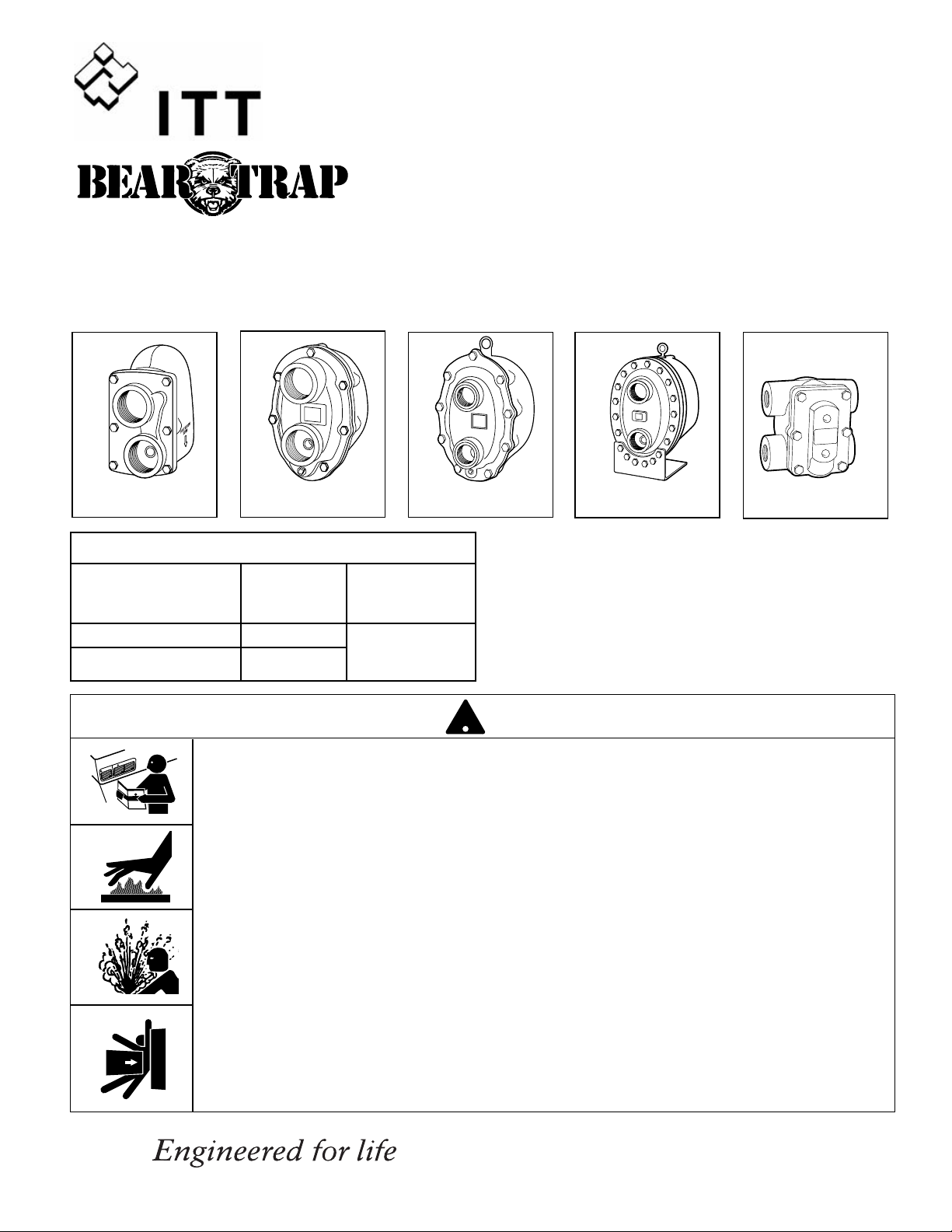
Series C
1
1
⁄4 & 11⁄2 NPT
Series C
2 NPT
Series X
2 NPT
Series C
2
1
⁄2 NPT
Series H
Ratings
Maximum Max. Operating
NPT Size - in. Temperature Pressure
°F (°C) psig (bar)
3
⁄4
”, 1” and
11⁄4
” H
406 (208)
175 (12.1)
11⁄4
” C and All
11⁄2
” -
21⁄2
”
377 (192)
Page 2
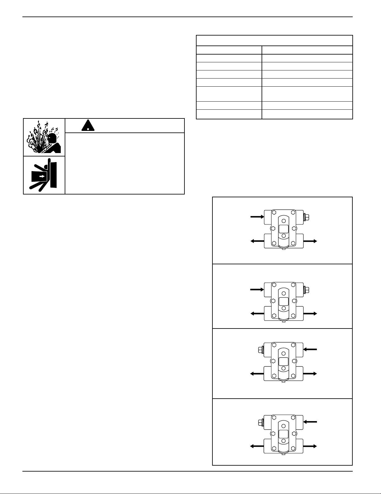
INLET
TEST
INLET
OUTLET
OUTLET
TEST
OUTLET
INLET
TEST
INLET
OUTLET
TEST
2
1. Determine where to install the trap, based on the
following requirements:
• The trap must be located as close as possible to, and
below the equipment to be drained.
• The trap must be in a straight run of horizontal pipe as
shown in the “Typical Piping Diagrams,” and pitched to
allow condensate to flow into trap inlet, and away from
trap outlet.
• Allow for enough space around the trap for servicing,
which may include removal of the body or cover,
depending on the model you are installing.
The Hoffman Series H traps provide an additional opening
where a test valve may be installed. On traps that do not
have an additional opening, the test valve can be installed
in a tee fitting in the discharge line.
OPERATION
Float and thermostatic traps have two basic elements: a
thermostat for venting air from the system during start-up
and a float assembly for draining condensate.
The thermostat is normally open. It allows air to vent until it
is within 10-30°F (4-12°C) of the steam temperature.
The float assembly drains condensate from the system
when buoyancy force lifts the float ball and opens the
valve. The weight of the float ball causes the pin to close
against the trap seat when condensate is not present.
Materials of Construction
Part Specifications
Body and Cover Cast Iron 30,000 psi tensile
Valve Pin and Seat Stainless Steel (Hardened)
Float Stainless Steel
Lever Assembly Stainless Steel
Thermostatic Air Vent Stainless Steel Cage and
Thermal Element
Cover Bolts Grade 5
Baffle Stainless Steel {21/2” units only}
To prevent serious personal injury from steam
pipe blow down, connect a temporary pipe
between the steam pipe opening and a drain,
or stand at least 100 ft. (30m) from the pipe
opening.
Failure to follow this warning could cause
property damage, personal injury, or death.
!
WARNING
INSTALLATION –
Series H, C and X Float and
Thermostatic Steam Traps
STEP 1
Page 3
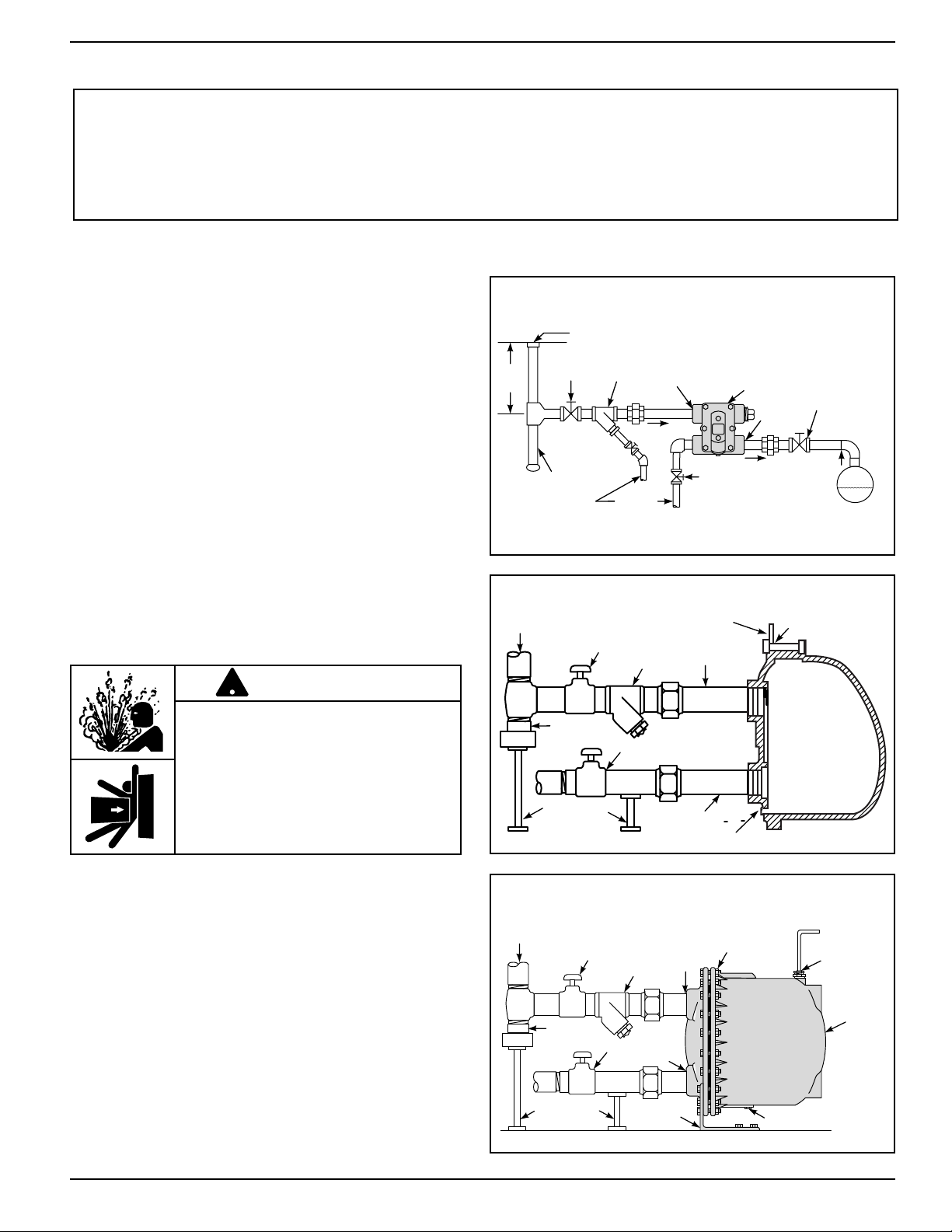
Shut-Off
Valve
"Y" Strainer
To Drain
To Return Line
Trap
Gravity Return to
Vented Receiver
Test Valve
Equipment Drain Point
Static
Head
Dirt Pocket
Inlet
Outlet
Shut-Off
Valve
Dirt
Pocket
Drain Plug
Outlet Valve
Supply
Inlet
Valve
Y Strainer
Cover Bolts
Thermostatic
Vent Pipe to
Gravity Return
Line or Drain
Pipe Supports
Support Foot
Inlet
Outlet
Trap
TYPICAL PIPING DIAGRAMS
Supply
Inlet
Valve
Y Strainer
Cover Bolts
Eye Hook
Dirt
Pocket
Pipe Supports
Drain Plug
Outlet Valve
Inlet
Outlet
Series H Trap Draining to Gravity Return Line
Series C and X Pattern Trap Installations
2
1
⁄2" Series C Pattern Trap Installations
• Install a Hoffman Specialty Y-strainer in the pipe,
ahead of the steam trap. This prevents dirt from
entering the trap.
• Install a blow down valve by connecting it to the
strainer drain plug. This allows the Y-strainer to be
cleaned.
• Install a shut-off valve in the inlet pipe and the outlet
pipe. This allows the trap to be isolated when
servicing.
• Install a test valve in the outlet pipe, and cap it. This
allows the trap to be tested. The cap is used as
safety precaution when the unit is not being tested.
• Blow down the piping using full steam pressure for
(5) five minutes. This cleaning process will remove
debris from the pipe and oil from the system.
Test traps by following the “Troubleshooting” procedure
on page 6.
3
To prevent serious personal injury from
steam pipe blow down, connect a temporary
pipe between the steam pipe opening and a
drain, or stand at least 100 ft. (30m) from
the pipe opening.
Failure to follow this warning could cause
property damage, personal injury, or death.
!
WARNING
STEP 2
IMPORTANT: To prevent system damage from water
hammer or sudden shock, open supply valves slowly.
If you are uncertain about the product’s adaptability
for your application, please call the factory or
authorized representative before using the product.
The trap seat rating (stamped on the nameplate) must
be equal to or greater than the maximum pressure
differential across the trap.
Page 4
4
REPAIR PROCEDURES FOR ALL TRAPS
REMOVAL FROM SERVICE
1. Close inlet and outlet supply valves and allow unit to
cool. If a test valve is installed, open this valve to
relieve any pressure.
2. Remove the drain plug to drain condensate from the
trap body.
3. Remove the bolts that attach the cover to the body.
SERIES H TRAPS
REPAIR
4. With cover assembly removed from trap body, remove
pin that holds lever assembly to yoke. Inspect seat
and pin for wear, replace if worn.
5. Inspect thermostatic element by placing it in boiling
water to see if it closes. If it doesn't close, replace it.
6. Check alignment of pin and seat, adjust or replace
parts as necessary.
7. Check float ball for damage, shake the float to make
sure there is no fluid inside the float. Replace if
necessary.
8. Clean gasket surfaces and install new cover gasket.
9. Reassemble the cover to the body. Tighten the bolts in
the indicated sequence shown on page 5. Torque all
bolts evenly to the indicated values.
SERIES C & X TRAPS
REPAIR
4. With body assembly removed from trap cover, remove
pin that holds lever assembly to yoke. Inspect seat
and pin for wear, replace if worn.
5. Inspect thermostatic element by placing it in boiling
water to see if it closes. If it doesn't close, replace it.
6. Check alignment of pin and seat, adjust or replace
parts as necessary.
7. Check float ball for damage, shake the float to make
sure there is no fluid inside the float. Replace if
necessary.
8. Clean gasket surfaces and install new cover gasket.
9. Reassemble the body to the cover. Tighten the bolts in
the indicated sequence shown on page 5. Torque all
bolts evenly to the indicated values.
To prevent serious burns, the internal
pressure of the trap must be 0 psi
(0 bar) before servicing.
Failure to follow this caution will
cause personal injury.
CAUTION
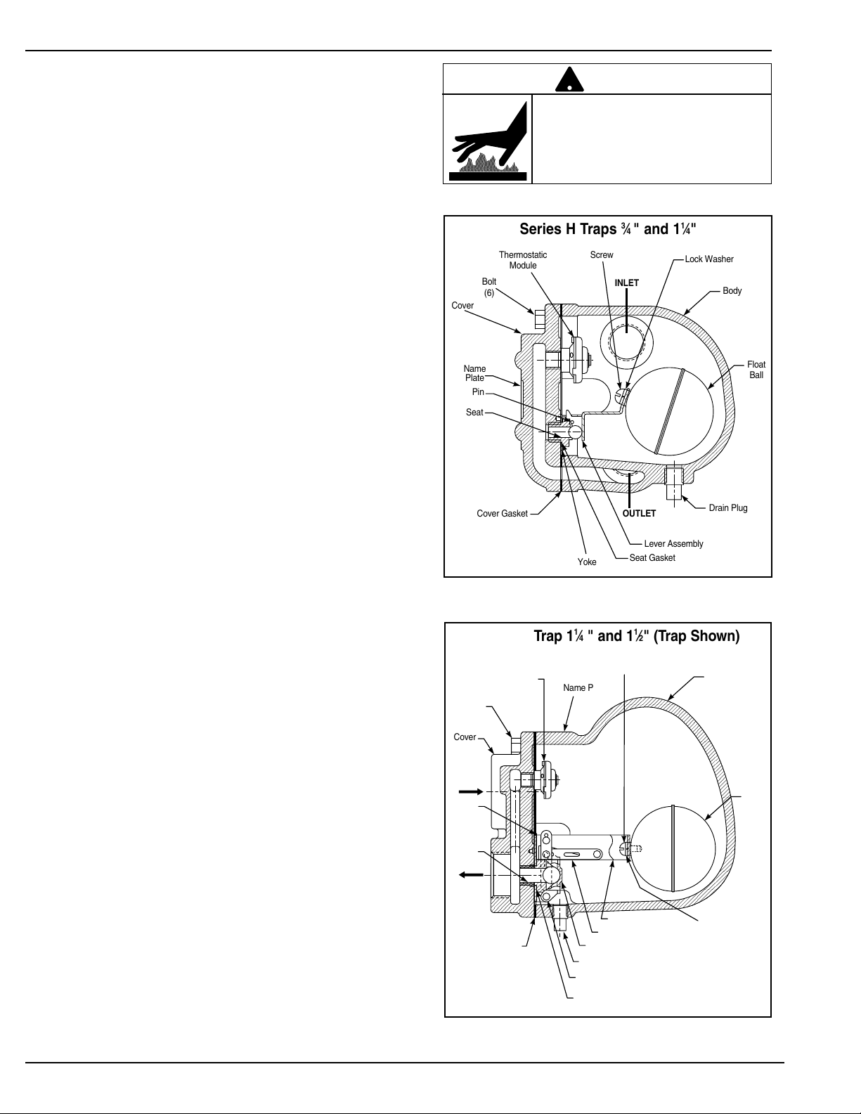
!
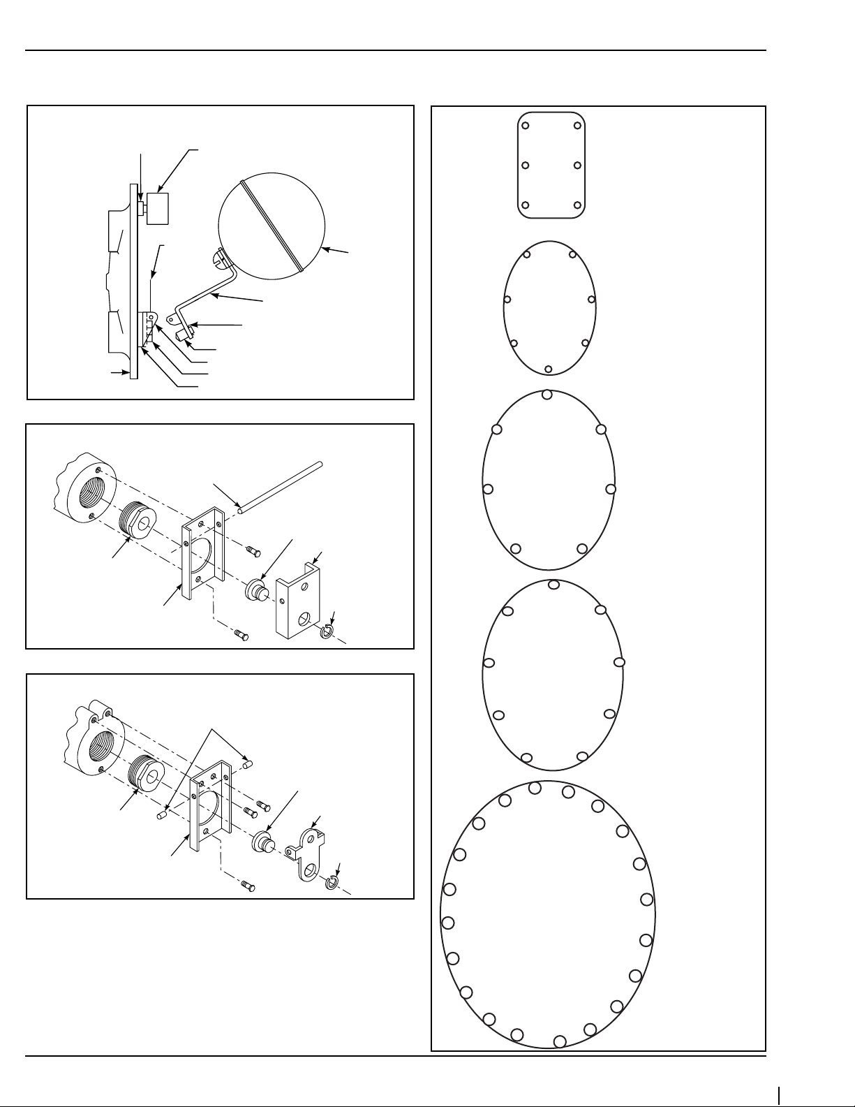
Thermostatic
Module
Cover
Bolt
(6)
Pin
Seat
Name
Plate
Cover Gasket
Yoke
Seat Gasket
Lever Assembly
Drain Plug
Float
Ball
Body
Lock Washer
Screw
INLET
OUTLET
Series H Traps 3⁄4 " and 11⁄4"
Cover
Name Plate
Seat Gasket
Pin (4)
Lever Seat Assembly
Lever Linkage (3)
Lever
Lock Washer
Cover Gasket
Seat
Yoke
Screw
Thermostatic
Module
Bolt
(6)
Body
Float
Ball
INLET
OUTLET
Drain Plug
Series C Trap 11⁄4 " and 11⁄2" (Trap Shown)
Page 5
5
RETURN TO SERVICE
10. Insert and securely tighten drain plug.
11. Open supply valve on trap outlet side, slowly open the
supply valve to the trap inlet.
12. Check for leaks and normal operation.
Test traps by following the “Troubleshooting” procedure on
page 6.
Gasket
Thermostat
Lever
Retainer
Clip
Lever
Assembly
“E” Ring
Cover
Yoke
Pin
Seat
Gasket
Float
Ball
19
18
14
10
6
2
4
8
12
16
20
17
13
9
5
1
3
7
11
15
8
4
2
6
9
7
3
1
5
7
4
2
6
3
1
5
4
7
2
5
3
6
1
5
1
3
4
2
6
Series C Trap Cover 2" Standard Capacity
Pin
Seat
Bracket
“E” Ring
Seat
Yoke
Pins
Seat
Bracket
“E” Ring
Seat
Yoke
Series X Trap Seat and Yoke 2"
Series C Seat and Yoke 2
1
⁄2" Units
Internal Component Detail Illustration
Cover Bolt Pattern Layout
Series H 3⁄4
" to 2" Traps and
Series C
11⁄4"and
11⁄2
" Traps
with six bolt pattern
Tighten Bolts to 28 +/- 3 ft-lbs.
(38 +/- 4 N-m) Torque
Series H
11⁄2
" and 2" Traps
with seven bolt pattern
Tighten Bolts to 28 +/- 3 ftlbs. (38 +/- 4 N-m) Torque
Series C 2" Traps
Tighten Bolts to 75 ft-lbs.
(102 N-m) Torque
Series X 2" Traps
Tighten Bolts to 150 ftlbs. (205 N-m) Torque
Series C
21⁄2" Traps
Tighten Bolts to 75
ft-lbs. (102 N-m)
Torque
Tighten and torque bolts in numerical order, beginning with #1.
Page 6

TROUBLESHOOTING
Problem:
1. Improper heating.
a. Cause: Thermostat failed closed and prevents
air from escaping.
Test: Blow air through the thermostat
when it is at normal room temperature, for a visual check. If air does not
pass through, the thermostat is not
functioning properly.
b. Cause: Float assembly failed closed and
caused condensate to back-up into the
steam space.
Test: Using a stethoscope, listen for a gur-
gling sound. No gurgling indicates that
condensate is not draining.
Using a thermometer, check the trap discharge temperature. If the temperature is
lower than normal, the condensate is not
draining.
c. Cause: Incorrect trap seat pressure selected.
Test: Check seat pressure rating on trap name-
plate. The seat pressure rating must be
equal or higher than the steam supply
pressure.
2. Energy wasted.
a. Cause: Thermostat failed open and allowed live
steam to blow through the trap.
Test: Using a stethoscope, listen for a low pitch
whistle as steam passes through the open
orifice. A whistle indicates the thermostat
failed open.
b. Cause: Float assembly failed open and allowed
live steam to blow through the trap.
Test: Install a test valve in the discharge line
from the trap outlet. Observe the trap
operation for steam leakage. Excessive
steam leakage indicates the float assembly
failed open.
Using a stethoscope, listen for a low pitch
whistle by positioning the stethoscope near
the thermostat or the float assembly. A
whistle indicates the thermostat or float
assembly (depending on where the stethoscope is positioned) failed open.
OR
OR
MAINTENANCE
When checked regularly and properly maintained, the
Series FT Float and Thermostatic traps will
provide optimum performance and long life.
SCHEDULE:
• Initially, every 2 - 3 days after start-up until
system is clean.
• Every 6 months thereafter.
1. Inspect joints for leaks. Stop all leaks by tightening
bolts and replacing gaskets, if necessary.
2. Clean strainers by opening the blow down valve
and allowing full steam pressure to flow out for (2)
two minutes. Then, close the valve.
To prevent serious burns, the internal
pressure of the trap must be 0 psi
(0 bar) before servicing.
Failure to follow this caution will
cause personal injury.
CAUTION
!
To prevent serious personal injury from steam
pipe blow down, connect a temporary pipe
between the steam pipe opening and a
drain, or stand at least 100 ft. (30m) from
the pipe opening.
Failure to follow this warning could cause
property damage, personal injury, or death.
!
WARNING
Hoffman Specialty
ITT
8200 N. Austin Ave.
Morton Grove, IL 60053
tel: 847-966-3700
fax: 847-966-9052
www.hoffmanspecialty.com
©2007 ITT Corporation
Printed in U.S.A. 6-07 510837
 Loading...