

Page 1

INSTALLATION AND MAINTENANCE INSTRUCTIONS
U S
s
s
C
1150-00001.
F6/F7...HD/HD
Butterfl y Valve
erie
Page 2

2
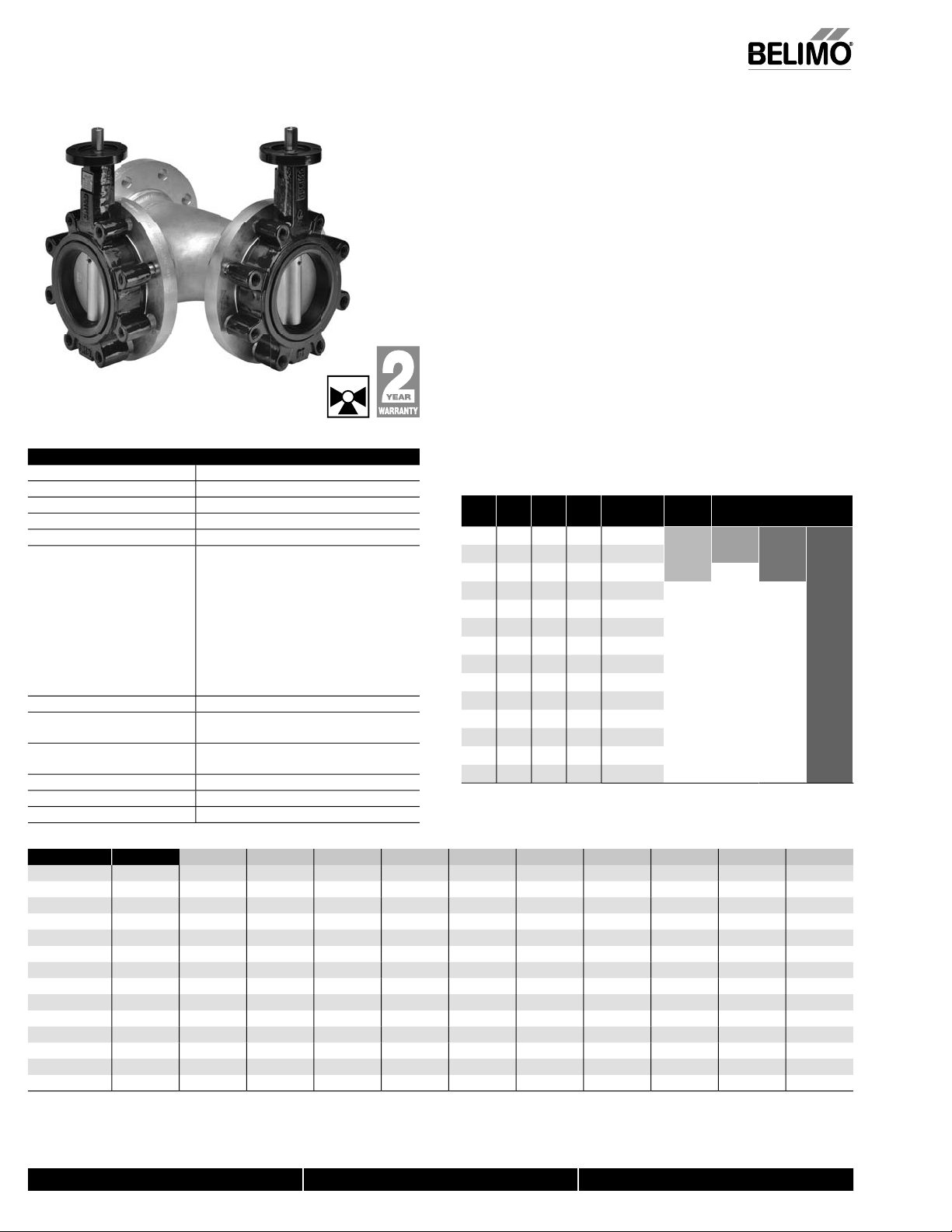
F6…HDU Butterfl y Valves 2”–12” Ductile Iron Lug Body
,
c
S
e
hilled, h
60% gl
l
c
m
Action
90°
S
s
2”
12”
Ty
g
M
ls
Body
h
sc
Seat
S
O
U
g
S
s
l
EPDM
416 stainless s
l
EPDM
g
30°F
°F)
i
y
y
S
g
y
n
hill
.
e
.
0
0HDU
HDU
U
U
U
9
U
U
U
50
U
U
5.06
0515
HDU
10
8.207075
U
6
HDU
”.50
U
”
6
7
”
U
7
9
U
4
1
7
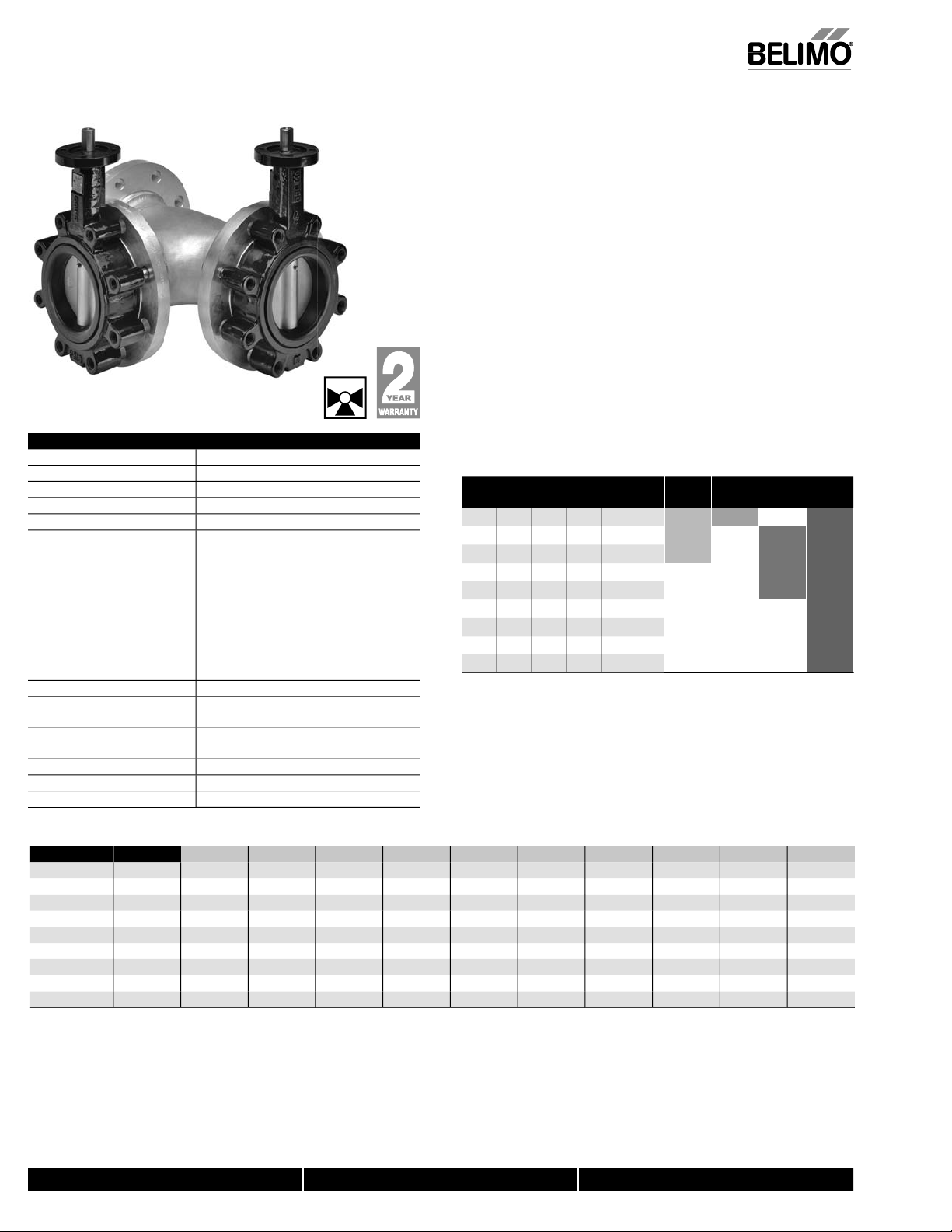
Resilient Seat
304 Stainless Dis
• 50 psi bubble tight shut-off
• Lon
stem design allows for 2” insulation
• Valve face-to-face dimensions compl
• Completely assembled and tested, ready for installation
pplicatio
These valves are designed to meet the needs of HVAC and commercial
applications requiring bubble tight shut-off for liquids. Typical applications
nclude c
air handler coil control, bypass and process control applications. The large
values provide for an economical control valve solution for larger fl ow
applications. Designed for use in Victaulic piping systems when mated to
ictaulic 41 series fl ange nipples
Jobsite Not
alves should be stored in a weather protected area prior to construction.
omplete installation recommendations can be found in Belimo’s Installation
and Maintenance Instructions for F6/F7…HD/HDU Butterfl y Valves
with API 609 & MSS-SP-67
er isolation, cooling tower isolation, change-over systems, large
Technical Data
ervic
Flow characteristi
ize
pe of end fi ttin
ateria
Body fi nis
Di
haft
-ring
pper bushin
Middle bushings
Lower bushing
edia temperature range
peration ambient
emperature range
ody pressure ratin
lose-off pressure 50 ps
Rangeabilit
aximum velocit
Valve Size
F650HD
5
2
c
for use with ANSI Class 125/150 fl anges
ductile iron A
epoxy powder coated
304
RPTFE
RPTFE
10:1 (for 30° to 70° range)
12 FP
ot water,
odifi ed equal percentage
rotation
to
TM A536
tainless stee
tee
22°F to 250°F [-30°C to 120°C]
22°F to 122°F [-30°C to 50°C]
SME/ANSI Class 125/150
psi at -
11
.
yco
to 275
°
alve
ominal Size
Cv
C
v
90°
60°
5
02 116
00
30
022
92 5” 125 F6125HD
7
136
202
4047 10”
2
°
° 40° 50°
7
2 12”
5
DN
IN
[mm]
5
” 80F680HD
” 100 F6100HD
” 150F6150HD
”
00 F6200HD
27 44
5
pe Suitable Actuators
2-way
F6250HD
F6300HD
MOD
Spring
5
5
° 70°
AF
AM
Series
Non-Spring
Series
GM
GM
1
7
SY Series
N/OFF
°
F6100HD
5
F6150HD
F6200HDU 8
F6250HD
F6300HD
600 .30
5
6
10”
12” 8250 4
800-543-9038 USA 866-805-7089 CANADA 203-791-8396 LATIN AMERICA
1579 .80 45
3136 2 89
340 3 151
3
6
5
88 408 727 1202 1903 2854
20
95
8139230 364 54
7
05 36
94 123
072 191
605 958 143
2047
3062 5005 750
240 485
600
579
136
5340
250
7/10 - Subject to change. © Belimo Aircontrols (USA), Inc.
Page 3
F6…HDU Butterfl y Valves 2”–12” Ductile Iron Lug Body
S
c
)
00.00.50
C
0
S
e
0
0
05.00.001.00.50
00.002.00.50
0
N
S
C
0
0
0
HDU
”
00.00
0.50
0
C
0
5
65.25.25.50.75
0
0
0
HDU
”
00.00.50.50
C
0
0
00.00.2
0
0HDU
340
8.00.00
0.2
C
0
C
0
.
.
.
.
.
0
0
0100
00
O
O
G
(
)
.
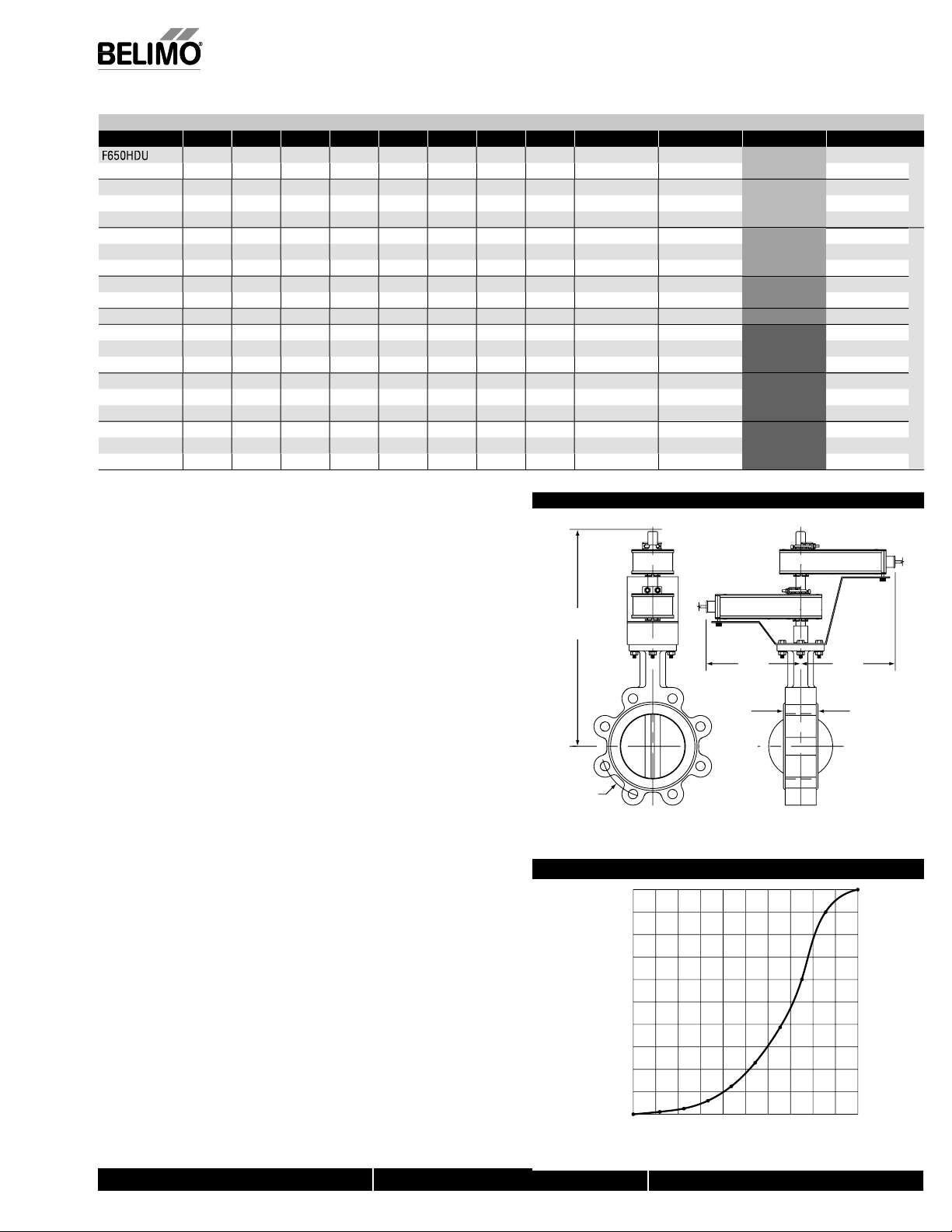
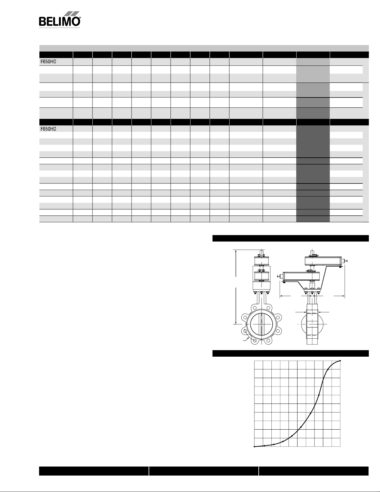
Resilient
Maximum Dimensions (Inches
Valve Size Cv 90° Cv 60° A B C D(Max) BHC No. of Holes Lug Bolt Actuator Close-Off (PSI)
F665HDU 2½”
F680HDU
F6100HDU 4”
F6125HDU
F650HDU 2”
F665HDU 2½”
F680HDU
F6100HDU 4”
5
5
F6150HDU
F650HDU 2”
F665HDU
F680HDU
F6100HDU 4”
5
5
F6150HDU
5
F6300HDU 12”
5
96
”
02
16 1.78
” 1022
15 44 1.65 7.00
96
”
02
00
” 1579
1
”
96 75 1.76
”
02
00
” 1579
16 1.78 7.00
30 2.05 8.00 8.00
05 2.19 8.00 8.00
44 1.
16 1.78
30 2.05 8.00 13.00
05 2.19 8.00 13.00
5
250 3062 3.01 8.00 13.00
.65
1.76
2.
2 2.14
1.76 7.00
.
.
.37
7
.5
.
.00
.00
.
.
.25
.25
.
.
.00
.00
.00
.00
.00
.25
.25
.75
0.00 5.50
0.50
5.00
.00
.75
5.50 5.50
6.00
7.00
.00
.50 8 5/8-11UNC
7.5
2.50
.50 8
6.00 5.50
6.25
2.00
3.00
.00
.50 8 5/8-11UNC
.50 8
5
5.5
7.25
7.00 12
.75
5
eat, 304 Stainless Dis
5/8-11UN
5/8-11UNC 5
5/8-11UNC
5/8-11UNC
4-10UNC
5/8-11UNC
5/8-11UN
5/8-11UNC 5
/4-10UNC 5
/4-10UN
5/8-11UNC
5/8-11UNC 5
5/8-11UNC 5
/4-10UN
/4-10UNC 5
/4-10UNC
/8-9UN
/8-9UN
A
*AF
MB(X)
MB(X)
MB(X)
SY1...
Y2...
Y3...
5
5
5
5
5
5
5
5
5
5
5
Fail
af
on-Fail
afe
Dimension “A” is compressed, add .125” for relaxed state.
Dimensions
AF, AM and GM maximum actuator ambient temperature is 122°F.
Y maximum actuator ambient temperature is 150°F.
odel SY1… does not have handwheel - override is via 8mm wrench on
bottom side of actuator.
Application Notes
1. Valves are rated at 50 psi differential pressure in the closed position
. Valves are furnished with lugs tapped for use with ANSI Class 125/150
anges. Installation fl anges and hardware are not included
C
3. 2-way assemblies are furnished assembled and tested, ready for installation
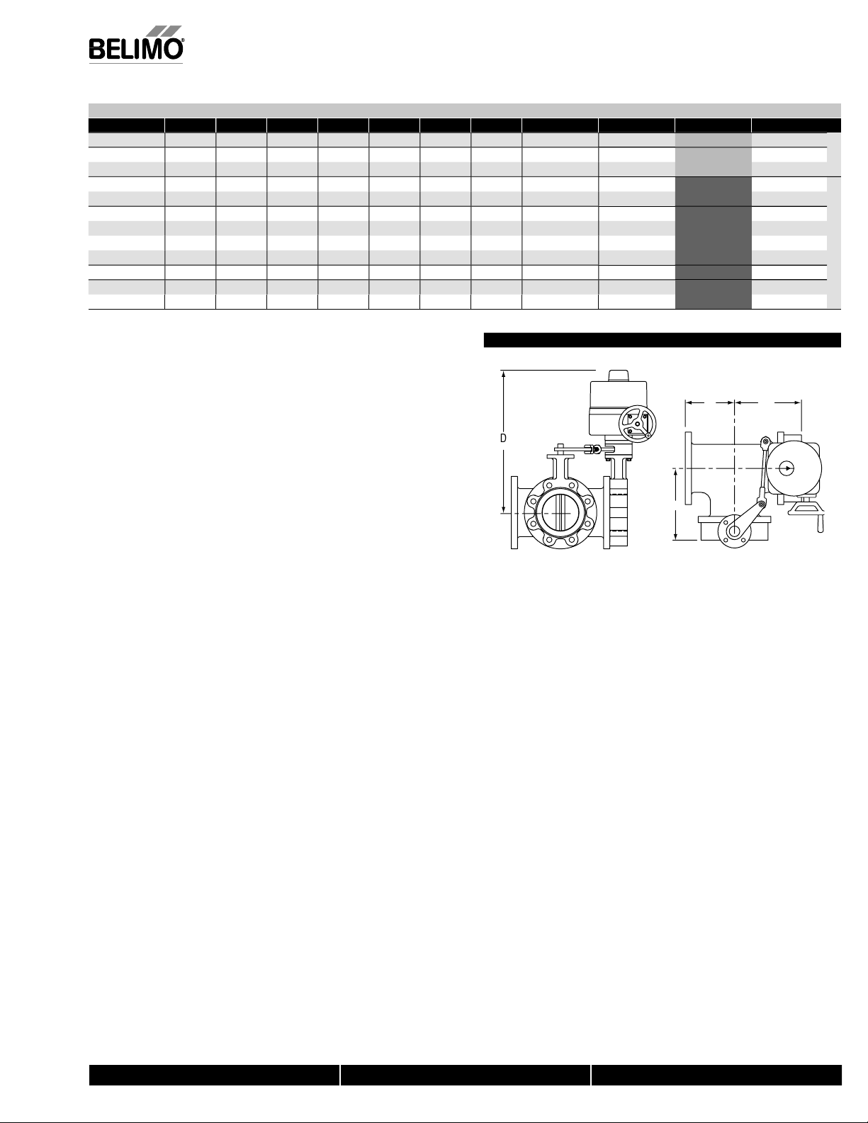
4. Dimension “D” allows for actuator removal without the need to remove the
valve from the pipe.
, Inc
5. Weather shields are available, dimensional data upon request
USA
6. Dual actuated valves have actuators mounted on a common valve shaft
. Belimo SY Series actuators are NEMA 4X rated.
Flow Pattern
0
W
7/10 - Subject to change. © Belimo Aircontrols
7
50
F MAXIMUM FL
%
2
4
% OF VALVE OPENIN
1
800-543-9038 USA 866-805-7089 CANADA 203-791-8396 LATIN AMERICA
Page 4
F7…HDU Butterfl y Valves 2”–12” Ductile Iron Lug Body
,
c
e
l
ic
r
n
12”
ls
y
h
t
t
g
g
g
l
less steel
30°F
°F)
e
i
y
)
y
S
g
y
n
s
n
y
e
0HDU
HDU
80HDU
100HDU
”
HDU
9
0HDU
U
U
U
0HDU
06
0
HDU
10
8
80HDU
2070
100HDU
30546
U
5029
0
U
7
200HDU
4
0HDU
1
95340
300HDU
0
2500
0750
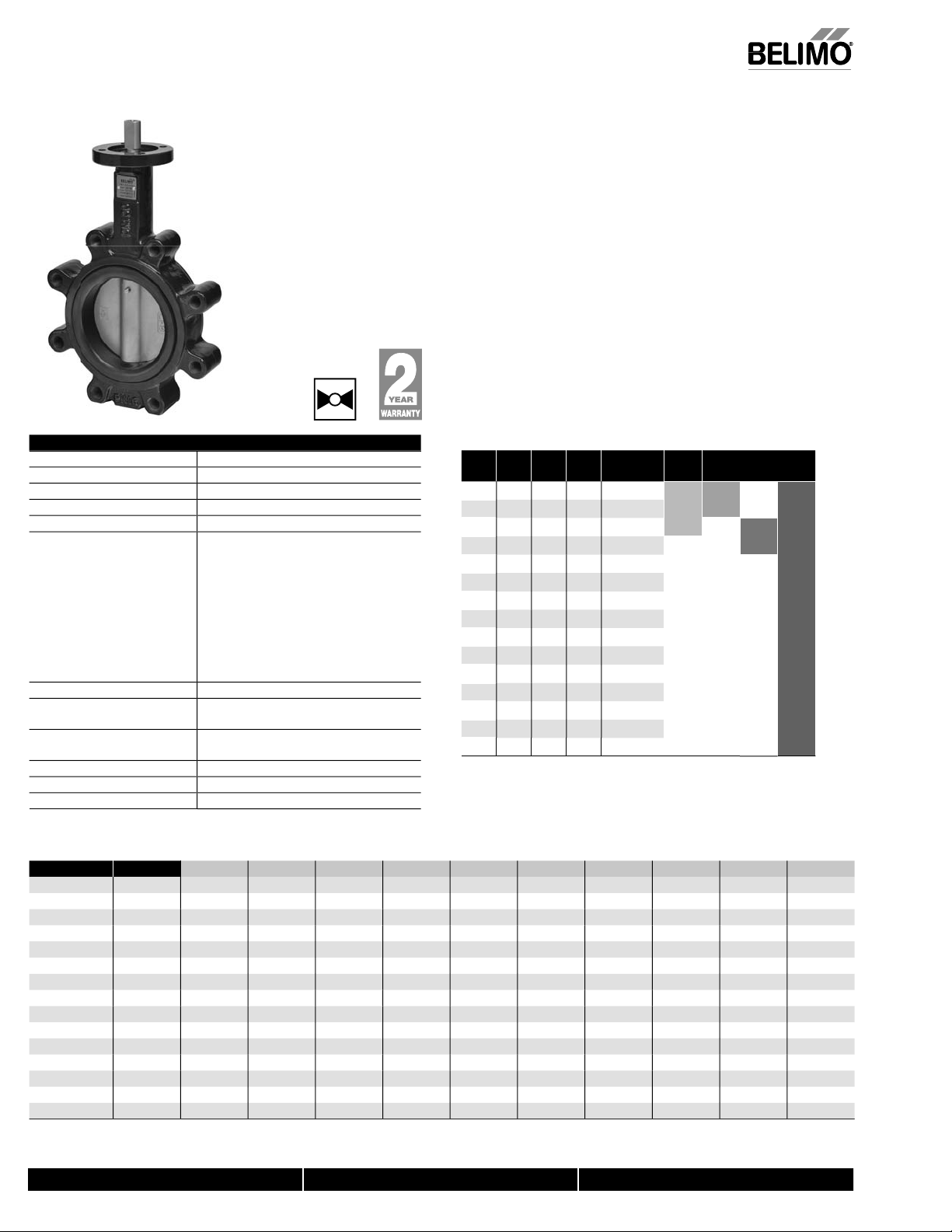
Resilient Seat
304 Stainless Dis
• 50 psi bubble tight shut-off
• Lon
stem design allows for 2” insulation
• Valve face-to-face dimensions compl
• Completely assembled and tested, ready for installatio
• Tees comply with ASME/ANSI B16.1 Class 125 fl ange
Applicatio
These valves are designed to meet the needs of HVAC and commercial
applications requiring bubble tight shut off for liquids. T
include chiller isolation, cooling tower isolation, change-over systems, large
air handler coil control, bypass and process control applications. The large
values provide for an economical control valve solution for larger fl ow
applications. Designed for use in Victaulic piping systems when mated to
ictaulic 41 series fl ange nipples.
obsite Not
alves should be stored in a weather protected area prior to construction.
omplete installation recommendations can be found in Belimo’s Installation
and Maintenance Instructions for F6/F7…HD/HDU Butterfl y Valves.
with API 609 & MSS-SP-67
pical applications
Technical Data
ervic
ow characterist
ctio
izes
Type of end fi tting for use with ANSI 125/150 fl anges
ateria
Bod
Body fi nis
ea
haf
O-rin
Upper bushin
Middle bushings
ower bushin
Media temperature range -22°F to 250°F [-30°C to 120°C]
eration ambient
temperature range -22°F to 122°F [-30°C to 50°C]
ody pressure rating ASME/ANSI Class 125/150
lose-off pressur
Rangeabilit
aximum velocit
Valve Size
75
765
7
7
F7125HD
F7150HD
7
725
7
” 1022 .
6” 1579 .80 45
chilled, hot water, 60% glyco
modifi ed linea
rotation
to
ductile iron ASTM A536
epoxy powder fi nish
stainless stee
standard
stain
RPTFE
RPTFE
psi at 50 ps
10:1 (for 30° to 70° range
12 FP
5 .
5
to 275
10°
.
.
.
0°
5
alve
ominal Size
Cv
C
v
90°
60°
5
7
136
202 8”200
5340
047 10” 250
250
062 12”
0°
1
5
5
0° 50°
5
5
05 366 605 958 143
7
IN
5
237
7
DN
[mm]
5075
00
7
7
pe
3-way
765
7
7
5
7125
715
7200HD
7250HD
7300HD
MOD
0° 70° 80° 90°
2
Spring
7
AF
Series
7
2
5 75
uitable Actuators
Non-Spring
AM
5
7
75
5
5
GM Series
SY Series
N/OFF
5
22
579
7/10 - Subject to change. © Belimo Aircontrols (USA), Inc.
800-543-9038 USA 866-805-7089 CANADA 203-791-8396 LATIN AMERICA
Page 5
F7…HDU Butterfl y Valves 2”–12” Ductile Iron Lug Body
,
c
)
0HDU
0.1
0
C
0
F
U
00.76.76.00.50
U
0
U
0
U
0
U
50
8.281.00.00
100HDU
0
0
C
0
C
0
0
0
U
01.00.58.58.00
5
U
0
.
3
.
S
0
S
S
G
(
)
.
Resilient Seat
aximum Dimensions (Inches
Valve Size Cv 90° A B C D(Max) BHC No. of Holes Lug Bolt Actuator Close-Off (PSI)
75
765HD
780HD
750HD
765HD
2½”
780HD
7
7125HDU 5”
7150HDU
7200HDU
7250HD
7300HD
10”
12”
”
” 302 5.50 7.28
”
”
”
”
5
.5
.
15 4.50 6.15
96 5.00 6.76
2
.
.5
7.2
.55
022 7.50 9.64
579
136 9.00
.00
0.19
1.37
4
250
2.00
5.01
5
.15
.28
.15
.76
.55
.64
0.19
1.37
5.5
6.25
5.50
6.00 5.50
.75 7.5
2.25 8.50 8
2.75
4.25 11.75 8
5.01 32.00 17.00 12
.75
.00
.75
.50 8
14.2
5/8-11UN
5/8-11UNC
5/8-11UNC 5
5/8-11UNC
5/8-11UNC 5
5/8-11UNC
5/8-11UN
/4-10UN
/4-10UNC 5
/4-10UNC
12
/8-9UNC
/8-9UNC 5
304 Stainless Dis
5
*AF
Y1…
Y2…
Y3…
Y4…
5
5
5
5
ail Safe
Non-Fail Safe
F maximum actuator ambient temperature is 122°F.
SY... maximum actuator ambient temperature is 150°F.
Model SY1… does not have hand wheel-override is via 8mm wrench on bottom
ide of actuator.
cation Notes
1. Valves are rated at 50 psi differential pressure in the closed position.
2. Valves are furnished with lugs tapped for use with ANSI Class 125/150
fl a nges. Installation fl anges and hardware are not included
. 3-way assemblies are furnished assembled and tested, ready for installation.
-way assemblies require the customer to specify the 3-way
All
onfi guration prior to order entry to guarantee correct placement of valves
nd actuators on the assembly.
. Dimension “D” allows for actuator removal without the need to remove the
alve from the pipe.
. Weather shields are available, dimensional data upon request
. Dual actuated valves have single actuators mounted on each valve shaft.
7. Bolts supplied are for shipping purposes only. Upon installation replace with
an appropriate
AE grade 5 or better hardware.
8. Belimo SY Series actuators are NEMA 4X rated.
, Inc
USA
Dimensions
P15
DW
H
7/10 - Subject to change. © Belimo Aircontrols
800-543-9038 USA 866-805-7089 CANADA 203-791-8396 LATIN AMERICA
Page 6
F6…HD Butterfl y Valves 2”–30” Ductile Iron Lug Body
,
c
e
ic
n
s
30”
g
s
yody
sc
t
t
g
g
S
ess steel
less steel
t
g
30°F
°F)
e
(2”-12”), 150
(14”-30”)
y
)
S
f
y
n
n
hill
.
.
e
050HD
”
HD579
050HD
340
050HD50
685050HD
050HD
908500500HD
28
0750HD
/
0HD
06
HD
1/2”
10
8
D
070116275
6
HD
”.5050HD579.80
8579
27
4
4
1
7
1
”
4
7
”
5
8
”
6
9
6
6208
05451701128146445451873426
Resilient Seat
Technical Data
ervic
ow characterist
ctio
Size
Type of end fi ttin
aterial
od
fi nish
i
ea
haf
O-rin
pper bushin
iddle bushings
ower bushing
edia temperature range -22°F to 250°F [-30°C to 120°C]
peration ambien
emperature range -22°F to 122°F [-30°C to 50°C]
ody pressure ratin
lose-off pressur
Rangeabilit
aximum velocity 12 FP
304 Stainless Dis
chilled, hot water, 60% glycol
modifi ed equal percentage
rotation
to
for use with ANSI 125/150 fl anges
ductile iron A
epoxy powder coated
4 stainl
EPDM standard
stain
ASME/ANSI Class 125/150
psi at -
psi
10:1 (for 30° to 70° range
TM A536
to 275
psi
• 200 psi (2” to 12”) and 150 psi (14”-30”) bubble tight shut-of
• Long stem design allows for 2” insulation
• Valve face-to-face dimensions compl
• Completely assembled and tested, ready for installatio
pplicatio
These valves are designed to meet the needs of HVAC and commercial
pplications requiring bubble tight shut-off for liquids. Typical applications
nclude c
ir handler coil control, bypass and process control applications. The large
values provide for an economical control valve solution for larger fl ow
pplications. Designed for use in Victaulic piping systems when mated to
ictaulic 41 series fl ange nipples
Jobsite Note
alves should be stored in a weather protected area prior to construction.
omplete installation recommendations can be found in Belimo’s Installation
nd Maintenance Instructions for F6/F7…HD/HDU Butterfl y Valves
C
v
90°
5
96
5
7
705
7
with API 609 & MSS-SP-67
er isolation, cooling tower isolation, change-over systems, large
lv
Nominal Size
C
v
IN
60°
½” 65 F665HD
5
5
7
5
5
DN
[mm]
5
75
ype Suitable Actuators
2-way
5
5
5
5
Spring
5
AF Series
Non-Spring
AM
GM
SY Series
Valve Size
5
5
H
6100HD 4
5
6300HD
6350HD
6400HD
6450HD
6500HD 20
6600HD 24
750HD
MODON
v
5 .
2 .2
600 .30 1
5
8250
4
6
8
800-543-9038 USA 866-805-7089 CANADA 203-791-8396 LATIN AMERICA
11917 6
16388 8 46
21705 1
27908 14
43116 22 1222 2587 5605
7342
0°
.
0°
3
38 715
1
91
1
0°
95
83
302
674
4
0° 50°
5
5
8139230
5
072 191
549 276
130
822 502
628
7
7
79
465 10698 16931 2539
98
0°
5
7
3062 5005 750
4568
6282 9942 14913
8320 13168 19752 21705
16528 26157 3923
0° 80° 90°
64 54
5
230 10844
OFF
5
7
5
5
2
600
7/10 - Subject to change. © Belimo Aircontrols (USA), Inc.
250
1917
6388
27908
43116
Page 7
F6…HD Butterfl y Valves 2”–30” Ductile Iron Lug Body
c
)
65.00.00.50.75
C
S
e
5
6.00.00.00.50
C
)
S
)
05.00.001.00.50
)
00.00.2
C
S
e
C
05.0013.00
5.50
00
9
9.0013.00
5.50
00.3
005.00.00
C
0.01.005.00.007.00
C
0HD
68.02.005.00.00
C
0
39
0015.004.50
516
C
†
5050HD70
13.00.00.2
C
†
0
C
285.94.00.0053.2
0
†
0
6.5
002.007.50.00
C
†
50
y.
n
.
.
p
.
.
U
070
O
U
O
G
Resilient Seat, 304 Stainless Dis
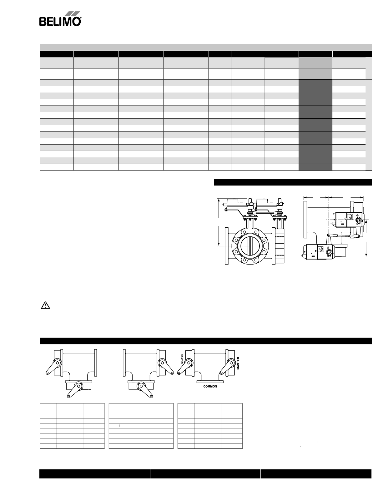
Maximum Dimensions (Inches
Valve Size Cv 90° Cv 60° A B C D(Max) BHC No. of Holes Lug Bolt Actuator Close-Off (PSI)
.
HD 2½”
680HD
650HD
665HD 2½”
680HD
100HD 4”
Valve Size Cv 90° Cv 60° A(Max) B (Max) C (Max) D(Max) BHC No. of Holes Lug Bolt Actuator Close-Off (PSI)
665HD 2½”
680HD
100HD 4”
6125HD 5” 1022
150HD
6250HD 10” 5340 2047 2.58 12.00 15.00
5
400HD 16”
6500HD 20” 27908
750HD
”
”
”
”
”157
” 734262814
7
1.7
02
15
96 75 1.76 7.00
02
96 75 1.76 8.00 13.00
02
16 1.78
1.65 7.00
16 1.78 8.00 8.00
2.
5
16 1.78 8.00 13.00
92 2.14 8.00 13.00
5
7
5
282
5
0698 5.00 14.00
5
.65
2.
2.1
7
.
.
7 14.
12.
.00
.
.
.00
.00
.00
1.00
0.50
5.00
5.50 5.50
6.00
0.75 5.50
1.00
1.7
2.25
2.7
0.00
1.50
5
4.25 12
1.2
5
5.00
5
.00
.75
.00
.75
.00
.50 8
.75
.75
.75
.5
5/8-11UN
5/8-11UNC
5/8-11UN
5/8-11UNC
5/8-11UNC
5/8-11UNC
5/8-11UNC
5/8-11UN
5/8-11UN
5/8-11UNC 200
5/8-11UNC 2
/4-10UNC 200
/4-10UNC
/4-10UN
/8-9UNC 200
/8-9UN
1-8UN
1-8UN
1 1/8-7UN
1 1/8-7UN
1 1/4-7UNC
1 1/4-7UN
*AF
MB(X
MB(X
*GMB(X
Y2…
Y3…
Y4…
Y5…
SY6…
Y8…
Y11…
Y12…
200
2
1
150
1
00
00
00
00
5
5
5
Fail
af
Non-Fail
afe
Non-Fail
af
imension “A” is compressed, add .125” for relaxed state.
SY6 and larger available in 110/220 VAC versions onl
AF, AM and GM maximum actuator ambient temperature is 122°F.
Y... maximum actuator ambient temperature is 150°F.
lication Notes
1. Valves are rated at 200 psi differential pressure in the closed positio
SY... 150 psi 14”+).
2. Valves are furnished with lugs tapped for use with ANSI Class 125/150
fl anges. Installation fl anges and hardware are not included
3. 2-way assemblies are furnished assembled and tested, ready for installation
. Dimension “D” allows for actuator removal without the need to remove the
valve from the pipe.
5. Weather shields are available, dimensional data u
6. Dual actuated valves have actuators mounted on a common valve shaft
7. Belimo SY Series actuators are NEMA 4X rated.
7/10 - Subject to change. © Belimo Aircontrols (USA), Inc.
on request
Dimensions
Flow Pattern
W
M FL
5
F MAXIM
DIM
BF2W
A
OF VALVE OPENIN
800-543-9038 USA 866-805-7089 CANADA 203-791-8396 LATIN AMERICA
Page 8
F7…HD Butterfl y Valves 2”–24” Ductile Iron Lug Body
,
c
e
ic
r
on
s
24”
g
s:
y
h
t
g
g
S
d
l
d
l
t
ge
g
)
e
(2”-12”), 150
(14”-24”)
bility
y
S
f
y
s
n
.
e
s
0750HD
HD
50
300
350HD
287600HD
0HD
0670
HD
1078780HD
2070757100HD
30546
5029237
010
0HD579.80
8579
200HD
4
015
0
0485940
1
7
1
4
”
7
50
05
5130
820131681975
05
”
Resilient Seat
Technical Data
ervic
ow characterist
Action
ize
Type of end fi ttin
Material
od
Body fi nis
eat
haf
O-rin
Upper bushin
e bushings
ower bushing
Media temperature range -22°F to 250°F [-30°C to 120°C]
peration ambien
temperature ran
ody pressure ratin
lose-off pressur
angea
Maximum Velocit
Valve Size
75
765
F7125HD
715
7
F7250HD
F7300HD
F7350HD
F7400HD
HD
F74
F7500HD 20
F7600HD 24
304 Stainless Dis
chilled, hot water, 60% glycol
modifi ed linea
° rotati
to
for use with ANSI 125/150 fl anges
ductile iron A
epoxy powder coate
stainless stee
416 stainless stee
PDM
RPTFE
-22°F to 122°F [-30°C to 50°C]
ME/ANSI Class 125/150
200 psi at -30°F to 275°F
psi
0:1 (for 30° to 70° range)
2 FP
5 .
1022 .
4
2
4
6
8250
11917
16388
217
27908 14 791 1674
3116 22 1222 2587 5605 9989 16528 26157 39236 43116
TM A536
standar
10°
.
.
.
11
psi
234
338 715
464
• 200 psi (2” to 12”) and 150 psi (14”-30”) bubble tight shut-of
• Long stem design allows for 2” insulation
• Valve face-to-face dimensions compl
• Completely assembled and tested, ready for installation
• Tees comply with ASME/ANSI B16.1 Class 125 fl ange
Applicatio
These valves are designed to meet the needs of HVAC and commercial
pplications requiring bubble tight shut off for liquids. Typical applications
nclude chiller isolation, cooling tower isolation, change-over systems, large
ir handler coil control, bypass and process control applications. The large
values provide for an economical control valve solution for larger fl ow
pplications. Designed for use in Victaulic piping systems when mated to
ictaulic 41 series fl ange nipples. Fail safe operation is possible with NSV-SY
eries battery backup systems
Jobsite Not
alves should be stored in a weather protected area prior to construction.
omplete installation recommendations can be found in Belimo’s Installation
nd Maintenance Instructions for F6/F7…HD/HDU Butterfl y Valves.
Cv
90°
5
02 116
00
22
579 605
3136 1202
4047
2
7
6388 6282
1705 8320
7908
°
5
1
1
°
2
95
83
2
°
5
412372047
072 191
549 276
130 379
22
628 6465 10698 16931 25396
alve
Nominal Size
C
v
IN
60°
5
”
30
” 100 F7100HD
2
”125F7125HD
” 150 F7150HD
” 200 F7200HD
” 250F7250HD
2
2”
6” 400 F7400HD
8” 450 F7450HD
0698
0” 500 F7500HD
5
7
2
with API 609 & MSS-SP-67
ype
DN
[mm]
2-way
5
5
765
F780HD
F7
7
MOD
°
2
5
3062 5005 750
4568 7230 1084
6282 9942 14913 16388
Spring
HD
uitable Actuator
AM
AF Series
°
2
5
5
24
Non-Spring
GM Series
2
SY Series
N/OFF
°
5
22
7/10 - Subject to change. © Belimo Aircontrols (USA), Inc.
8250
11917
17
7908
8
800-543-9038 USA 866-805-7089 CANADA 203-791-8396 LATIN AMERICA
Page 9
F7…HD Butterfl y Valves 2”–24” Ductile Iron Lug Body
S
c
)
F
e
80HD
07.28.28.00.00
C
50.6
5.50
00
579.00.19.19
5.50
007200HD
00.3
00
C
C
0HD
007.027.02.00
C
†
0
00.39.39.50
516
50
05.5020.63.63.50
516
†
50
00HD
908.00.00.00.505.00
C
0
600HD.007.97.953.2
0
C
†
0
63
G
L
S
G
G
S
C
C
S
OD@
C
S
3X3
3
y
S
R
O
S
E
O
S
R
E
.
).
.
.
ON
.
y.
.
fi
eed to remove
.
0
0
D
AB
C
G
(
)
.
Resilient
Maximum Dimensions (Inches
Valve Size Cv 90° A B C D(Max) BHC No. of Holes Lug Bolt Actuator Close-Off (PSI)
F750HD 2”
15 4.50 6.15
.15
0.25
.75
eat, 304 Stainless Dis
5/8-11UNC
00
ail Saf
F765HD 2½”
F750HD 2”
F765HD 2½”
7
F7100HD 4”
F7125HD
F7150HD
F7250HD
F7300HD
0” 5340
2”
735
F7400HD
F7450HD
75
” 1022 7.
”1
”
” 217
96 5.00 6.76
15 4.50 6.15
96 5.00 6.76
5.5
00 6.50
.
1.00
250
2.00
7
.
.
7
.55
4
7
3.58
5.01
7
AF maximum actuator ambient temperature is 122°F.
Y... maximum actuator ambient temperature is 150°F.
†SY6 and larger available in 110/220 VAC versions onl
Application Notes
1. Valves are rated at 200 psi differential pressure in the closed position.
. Valves are furnished with lugs tapped for use with ANSI Class 125/150
fl a nges. Installation fl anges and hardware are not included
3. 3-way assemblies are furnished assembled and tested, ready for installation.
ll 3-way assemblies require the customer to specify the 3-way
con
guration prior to order entry to guarantee correct placement of valves
and actuators on the assembly.
4. Dimension “D” allows for actuator removal without the n
valve from the pipe.
5. Belimo SY Series actuators are NEMA 4X rated.
5. Weather shields are available, dimensional data upon request
6. Dual actuated valves have single actuators mounted on each valve shaft.
. Bolts supplied are for shipping purposes only. Upon installation replace with
, Inc
USA
n appropriate SAE grade 5 or better hardware.
ote: For tee confi guration, please refer to page 4
.76
.15
.76
.55
.64
0.75 5.50
0.25
.75
0.75 5.50
1.75
.50 8 5/8-11UNC 200
2.2
2.7
.37
.
.75
3.58 30.00 14.25 12
5.01 32.00 17.00 12
.75
1.2
2.7
5
.5
Dimensions
the
5/8-11UNC
5/8-11UNC
5/8-11UNC 200
5/8-11UN
4-10UNC
4-10UNC 2
/4-10UN
/8-9UN
/8-9UNC
1-8UN
1-8UNC
1 1/8-7UNC
1 1/8-7UN
1 1/4-7UN
*AF
Y2…
Y3…
Y4…
Y5…
SY6…
SY7…†
Y9…
Y12…
200
2
200
200
1
1
10
00
Non-Fail Safe
5
5
5
11
DW
10
3-Way Confi guration Codes
D1
TE
A
N
MM
N
MM
T
LAV
MA
TE
MA
NOTES
1. Slave Valve operates inversely of the Master Valve.
. The Master Valve is always located on the run
3. The Slave Valve may also have an actuator if
equired (Direct Coupled
7/10 - Subject to change. © Belimo Aircontrols
MOD@2VD
NFI
DE
11
X Specifies Bi-Directional Flow Capabilit
N/OFF OR
ASTER
VALVE I
PEN
PEN
PEN
CLOSED
LOSED
LOSED
LAVE
ASTER
VALVE
FAI
N-FAIL
PEN
LOSED
ON-FAIL
PEN
LOSED
NFI
DE
X
X
X
X
X
LAVE
N/OFF OR
D@2VD
MASTER
ALVE I
PEN
PEN
PEN
LOSED
LOSED
LOSED
ASTER
VALVE
FAIL
N-FAIL
PEN
LOSED
ON-FAIL
PEN
LOSED
X
X
X33
X3
X3
MMON
N/OFF OR
2VD
M
NFI
ASTER
DE
VALVE I
PEN
PEN
1
PEN
LOSED
LOSED
LOSED
MA
VALVE
FAIL
N-FAIL
PEN
LOSED
ON-FAIL
PEN
LOSED
TER
4. On/Off actuator normal position is a function of
fi eld logic
5. Proportional actuator normal position is a function
f the CCW/CW switch.
6. All 3-way assemblies are designed for 90 degree
ctuator rotation
RDERING INFORMATI
Please note that HD series BF valves over 18” and
ALL sizes 3-way tee assemblies ordered with
are special order/custom
built and are
returnable.
800-543-9038 USA 866-805-7089 CANADA 203-791-8396 LATIN AMERICA
9
Page 10
0
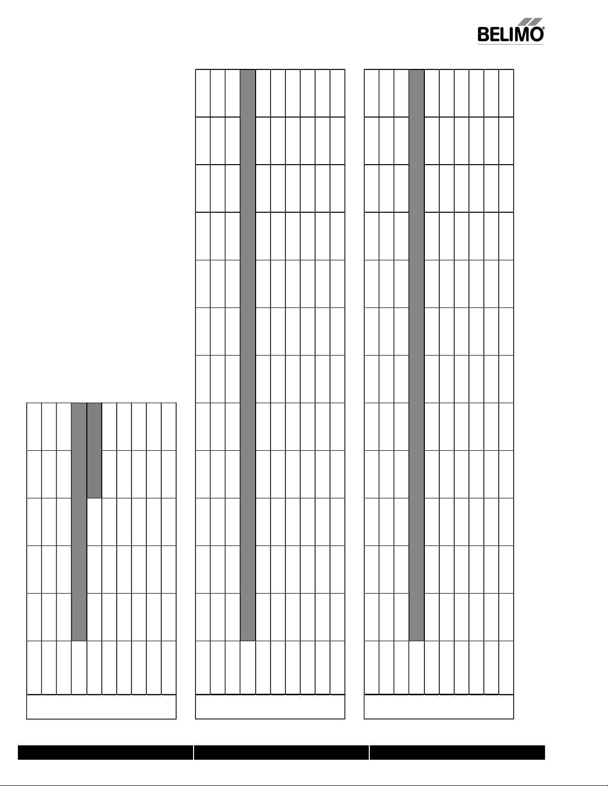
Wire Size vs. Length of Run for SY Series Actuators
g
A
ps
A
ps
A
ps
A
ps
A
ps
i
g
ge
8
5
6
4
0
0
2
4
0
0
4
8
3
3
1
C
A
s
A
s
A
s
A
s
A
s
A
s
A
s
A
s
A
s
A
s
A
s
A
s
i
g
ge
3
5
8
2
2
8
8
8
83
05
89
89
3
89
6
90
90
6
94
2
2
6
923
9
068
8
8
2
634
9
35
9
35
35
0
000
000
6
8
63
2
0
63
0
2
0
925
63
63
5
6
866
88
866
1
C
A
ps
A
ps
A
ps
A
ps
A
ps
A
ps
A
ps
A
ps
A
ps
A
ps
A
ps
A
ps
g
ge
3
5
5
6
7
8
6
6
6
2
8
0
5
5
4
8
8
9
6
937
62
62
0
6
88
90
88
90
88
082
1
2
5
8
4
8
2
8
5
4
3
6
1
4
0
666
286
00
0
000
0
000
0
9
51
8
6
322
63
63
84
2
C
Y11 SY12
Y10
Y9
Y8
Y7
Y6
mp
mp
mp
mp
mp
mp
mp
1
1
7
5
41 4
4
.
.
1.
1
71
14
7
1
71
1
7
1
1
1
5
7
7
1
7
1
1
71
4
5
5
5
1
1
15
77
14
Y12
Y11
Y10
Y9
Y8
Y7
Y6
m
2.
m
1.
m
m
1.
m
m
1.
.
m
947 68
947 75
47 75
189
1
4
1
4
11
14
7
923 2404 174
1923 2404
240
80
676 267
676 2941
294
367
7
5
5
74
5
5
74
5
5
ed to 120 VAC models.
Y5
Y4
Y3
Y2
Y1
.
m
m
m
m
.
m
7
7
40 7
14 1
1
33 14
57
64 182 16
06 36
7
4
4
Y5
Y4
Y3
Y2
Y1
mp
mp
mp
mp
mp
1.
5
MAX Distance between Actuator and Supply (feet)
1.
.5
5
75
75
7
1
47
1
1
111
4
11
41
41
7
4
5741
5
74
5
74
4
Y5
Y4
Y3
Y2
Y1
.
m
.
m
.
m
.
m
.
m
MAX Distance between Actuator and Supply (feet)
au
re
w
181
1
1
1
24 VA
au
re
w
1
1
1
1
au
wire
10 VA
1
16
4
49
MAX Distance between Actuator and Supply (feet)
52
030
5051 303
1
7
47
7
1
410
7692
769
282
8403 735
80
176
1765
960
1
4
1
7
7
4
1
1
7
4
1
7/10 - Subject to change. © Belimo Aircontrols (USA), Inc.
20 VA
he same conduit. Generally, 24 VAC actuators over 100 VA should be chan
The NEC mandates that 24 VAC over 100 VA power requires CLASS 1 wiring conduit. Local codes may vary. Do NOT mix CLASS 1 & CLASS 2 circuits in
800-543-9038 USA 866-805-7089 CANADA 203-791-8396 LATIN AMERICA
1
Page 11

il
V
+
-
n
V
+
-
Adaption
A
V
Actuators: SYx-MFT
pply
n
(
)
.
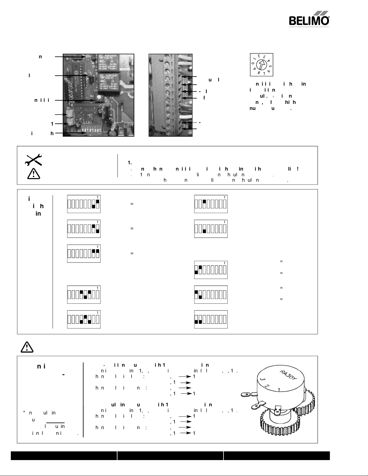
INSTALLATION NOTES
CAUTION
nterface Wiring Deta
Yx-MFT, 24V, 120/230
tes:
1. Motor CAMS have been factory calibrated and should not be moved.
. An adaption must be performed if any limit switch is adjusted. This will
calibrate the beginning and end stopping points. Press the adaption
utton for 3 seconds and release.
, Inc
USA
Control Signal
Control Signal
FDBK +
FDBK -
Adaptio
PC Tool Service Jack Connection
rection of Rotation
Power Supply Hot +
4
- Power Su
- Power Supply Hot
Commo
Power Supply Com -
7/10 - Subject to change. © Belimo Aircontrols
Control Signal
Control Signal
FDBK +
-
PC Tool Service Jack
rection of Rotation
800-543-9038 USA 866-805-7089 CANADA 203-791-8396 LATIN AMERICA
120/230
1
Page 12
2
SYx-P Interface Wiring Detail
C
A
UT-5VDC
C
A
OSS
S
SE
T
OSS
D
)
OSS
N
)
OSS
N
OSS
D
g)
N
N
N
N
/
.
L
i
o
-
INSTALLATION NOTES
CAUTION
FF
N
FF
N
FF
N
FF
N
FF
N
INP
:
pplicable to the SY1 and legacy SY2-12 actuators
.
-10D
5
4-20m
TPUT=
TPUT=
-20m
-10VD
2
FF
RESPONSE = DIREC
O
FF
RESPONSE = REVER
O
L
F
FF
L
O
2
L
1
FF
L
2
1
FF
L
O
IGNALLOSE
F
IGNALPE
R
rse Acting
F
IGNALPE
DirectActing)
F
IGNALLOSE
F
IGNAL =
DirectActing
verse Actin
WARNING
t
7/10 - Subject to change. © Belimo Aircontrols (USA), Inc.
F
800-543-9038 USA 866-805-7089 CANADA 203-791-8396 LATIN AMERICA
1
Page 13
s
Counter-clockwise Increase Closed Angle
Counter-clockwise Decrease Opening Angle
S
5
85
90°
°
°
3
S4
S1LS2
S3
n
n
Counter-clockwise Increase Closed Angle
Counter-clockwise Decrease Opening Angle
d
WARNING
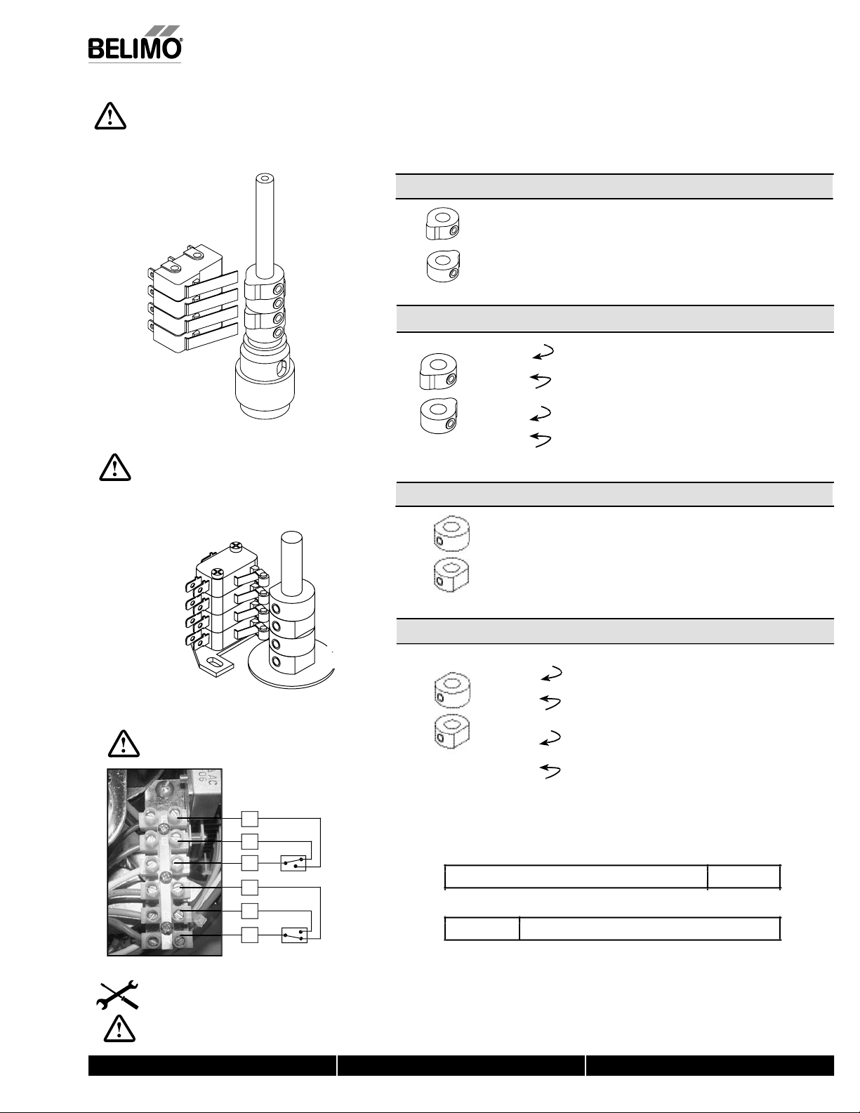
Electrical Travel Adjustment (Factory Pre-set
)
1
CAUTION
CAUTION
g
g
CAUTION
INSTALLATION NOTES
(
)
.
SY-
actory pre-set see chart below. Field adjustable if required
Factory pre-set and calibrated. Do not adjust - warranty voided
SY… Series Non-Spring Actuator
S4
uxiliary Switch for Closed Indicatio
uxiliary Switch for Opened Indicatio
LOSE”
PEN”
Electrical Travel Adjustment
Y-2-12
LS4
L
, Inc
USA
7/10 - Subject to change. © Belimo Aircontrols
L
LS
L
actory pre-set see chart below. Field adjustable if required
LS4
uxiliary Switch for Closed Indication
L
3
uxiliary Switch for Opened Indication
Factory pre-set and calibrated. Do not adjust - warranty voide
“CLOSE”
“OPEN”
witches at left are shown with actuator fully open.
0°
0° 5
°
85° 90
°
800-543-9038 USA 866-805-7089 CANADA 203-791-8396 LATIN AMERICA
tes:
. An adaption must be performed when the limit switches are adjusted. For
the SYx-MFT actuators. This will calibrate the be
oints. Press the adaption button for 3 seconds and release.
inning and end stoppin
3
Page 14
W
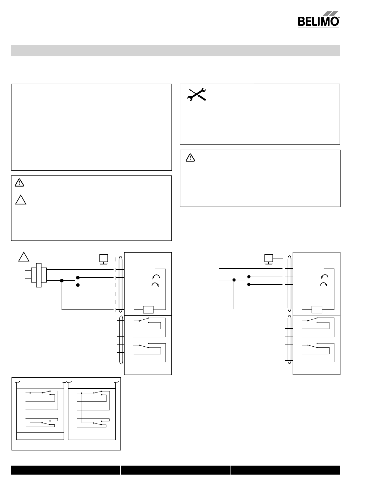
iring for Damper Actuators and Control Valves
,
On/Off
Actuators: SY1-24 SY1-110 SY2...12-110 SY2...12-220
24V, 120/230V
546
Hazard Identification
Warnings and Cautions appear at appropriate sections throughout
this manual. Read these carefully.
CAUTION
Indicates a potentially hazardous situation which, if not avoided,
may result in minor or moderate injury. It may also be used to
alert against unsafe practices.
Indicates an action or condition that may cause irreversible
damage to the actuator(s) or associated equipment.
Equipment damage!
Power consumption and input impedance must be observed.
NOTES SY1…5-24
Each actuator should be powered by a single, isolated
33
control transformer.
s)SOLATIONRELAYSMUSTBEUSEDINPARALLELCONNECTIONOFMULTIPLEACTUATORS
using a common control signal input.
s(CANNOTBECONNECTEDTOTERMINALANDSIMULTANEOUSLY
sRequired: 4ERMINALNEEDSTOBEFIELDWIREDTOENABLEHEATERCIRCUIT
G
G Ground
1 Common
3 Open
4 Closed
Connect to #1 for fully
5
open indication
Connect to #1 for fully
6
closed indication
7
HTR
Line
Volts
24 VAC Transformer
33
Open
Close
INSTALLATION NOTES
Observe class 1 and class 2 wiring restrictions.
Transformer sizing = SY actuator draw X 1.25 (safety margin)
(Ex. SY2-24 requires 3.0A x 1.25 = 3.75A,
3.75A X 24 VAC = 90VA Transformer).
NOTES SY1…12-110 (220)
sCaution: Power Supply Voltage
s)SOLATIONRELAYSMUSTBEUSEDINPARALLELCONNECTIONOFMULTIPLEACTUATORS
using a common control signal input.
s(,CANNOTBECONNECTEDTOTERMINALANDSIMULTANEOUSLY
sRequired: 4ERMINALNEEDSTOBEFIELDWIREDTOENABLEHEATERCIRCUIT
120 and 230 VAC
N L1
H L2
G
Open
Close
G Ground
1 Common
3 Open
4 Closed
Connect to #1 for fully
5
open indication
Connect to #1 for fully
6
closed indication
HTR
7
A
LS3
B
A-B (Open Indication)
C
Contact Rating: 5A 125 VAC Max.
3A 250 VAC Max.
E
F
LS4
A-E (Closed Indication)
SY1-24
SY1 Contact Arrangements
800-543-9038 USA 866-805-7089 CANADA 203-791-8396 LATIN AMERICA
14
A
B
A-B (Open Indication)
C
Contact Rating: 5A 125 VAC Max.
3A 250 VAC Max.
E
F
A-E (Closed Indication)
SY1-110 (220)
A
LS3
B
(Open Indication)
A-C
C
D
LS4
E
(Closed Indication)
D-F
F
Contact Rating: 5A 250 VAC Max.
SY2…5-24
A
LS3
B
A-C
(Open Indication)
C
D
LS4
E
D-F
(Closed Indication)
F
Contact Rating: 5A 250 VAC Max.
SY2…12-110 (220)
7/10 - Subject to change. © Belimo Aircontrols (USA), Inc.
LS3
LS4
Page 15

p
V
Actuators: SY1-24P SY1-110P SY1-220P
(
)
.
547
Hazard Identification
7ARNINGSAND#AUTIONSAPPEARATAPPROPRIATESECTIONSTHROUGHOUT
this manual. Read these carefully.
CAUTION
)NDICATESAPOTENTIALLYHAZARDOUSSITUATIONWHICHIFNOTAVOIDED
may result in minor or moderate injury. It may also be used to
alert against unsafe practices.
Indicates an action or condition that may cause irreversible
damage to the actuator(s) or associated equipment.
%QUIPMENTDAMAGE
0OWERCONSUMPTIONANDINPUTIMPEDANCEMUSTBEOBSERVED
Wiring for Damper Actuators and Control Valves
Pro
ortional, 24V, 120/230
INSTALLATION NOTES
/BSERVE#LASSAND#LASSWIRINGRESTRICTIONS
4RANSFORMERSIZING39ACTUATORDRAW8SAFETYMARGIN
%X39REQUIRES!X!!86!#6!4RANSFORMER
APPLICATION NOTES
Ground shielded wire at control panel chassis.
34
Tape back ground at actuator.
36
Use of feedback is optional.
, Inc
USA
NOTES SY1…24P
Each actuator should be powered by a single, isolated
33
control transformer.
s0OWERSUPPLY#OM.EUTRALAND#ONTROL3IGNAL "–" wiring to a common is
prohibited. Terminals 4 and 6 need to be wired separately.
s$ONOTCHANGESENSITIVITYORDIPSWITCHSETTINGSWITHPOWERAPPLIED
24 VAC Transformer
33
Line
Volts
Control signal
Feedback
G
G Ground
4 Power Supply Com
5 Power Supply Hot
6 Control Signal (-)
7 Control Signal (+)
34
8 Internal Use Only
9 Internal Use Only
10 Internal Use Only
11 Feedback (-)
12 Feedback (+)
36
A
B
!"/PEN)NDICATION
C
#ONTACT2ATING !6!#-AX
!6!#-AX
E
F
!%#LOSED)NDICATION
SY1-24P
NOTES SY1…110P (220P)
sCaution:0OWERSUPPLYVOLTAGE
s0OWERSUPPLY#OM.EUTRALAND#ONTROL3IGNAL "–" wiring to a common is
prohibited. Terminals 4 and 6 need to be wired separately.
s$ONOTCHANGESENSITIVITYORDIPSWITCHSETTINGSWITHPOWERAPPLIED
120 and 230 VAC
G
N L1
H L2
Control signal
34
Feedback
36
LS3
LS4
G Ground
4 Power Supply Com
5 Power Supply Hot
6 Control Signal (-)
7 Control Signal (+)
8 Internal Use Only
9 Internal Use Only
10 Internal Use Only
11 Feedback (-)
12 Feedback (+)
A
LS3
B
!"/PEN)NDICATION
C
#ONTACT2ATING !6!#-AX
!6!#-AX
E
F
LS4
!%#LOSED)NDICATION
SY1 -110P (220P)
7/10 - Subject to change. © Belimo Aircontrols
800-543-9038 USA 866-805-7089 CANADA 203-791-8396 LATIN AMERICA
5
Page 16

W
iring for Damper Actuators and
C
s
2
ŏ
ŏ
ŏ
ŏ
ŏ
L
ontrol Valve
Proportional, 24V, 120/230V
Actuators: SY2...5-24MFT SY2...12-120MFT SY2...12-230MFT
Hazard Identification
7ARNINGSAND#AUTIONSAPPEARATAPPROPRIATESECTIONSTHROUGHOUT
this manual. Read these carefully.
CAUTION
Indicates a potentially hazardous situation which, if not avoided,
may result in minor or moderate injury. It may also be used to
alert against unsafe practices.
Indicates an action or condition that may cause irreversible
damage to the actuator(s) or associated equipment.
%QUIPMENTDAMAGE
0OWERCONSUMPTIONANDINPUTIMPEDANCEMUSTBEOBSERVED
NOTES SY2...5-24MFT
Each actuator should be powered by a single, isolated
33
control transformer.
s0OWERSUPPLY#OM.EUTRALAND#ONTROL3IGNAL "–" wiring to a common is
prohibited.
Control Signal
Feedback
36
34
Control Signal (+)
Control Signal (-)
Feedback Signal (+)
Feedback Signal (-)
Not Used -
Not Used -
INSTALLATION NOTES
W547-
/BSERVE#LASSAND#LASSWIRINGRESTRICTIONS
4RANSFORMERSIZING39ACTUATORDRAW8SAFETYMARGIN
%X39REQUIRES!X!!86!#6!4RANSFORMER
APPLICATION NOTES
Ground shielded wire at control panel chassis.
34
Tape back ground at actuator.
36
Use of feedback is optional.
NOTES SY2...12-120MFT (230MFT)
sCaution:0OWERSUPPLYVOLTAGE
A
Internal Use Only
B
PC Tool
Service Jack
Y
1
U5
2
C1
C2
Address
Adaption
Y1Y2
SYx-24MFT
1
2
3
/-
~/+
8
9
10
Internal Use Only
Internal Use Only
Internal Use Only
Internal Use Only
Power Supply Com
Power Supply Hot
Internal Use Only
Internal Use Only
Internal Use Only
24VAC
33
Control Signal
A
B
C
E
F
SY2...5-24MFT
SY2...12-120MFT
16
G
PE
Power Supply Com – 120v (N) / 230v (L1)
Power Supply Hot – 120v (H) / 230v (L2)
A
B
1
2
3
8
9
10
Internal Use Only
Internal Use Only
Internal Use Only
Internal Use Only
Internal Use Only
Internal Use Only
Internal Use Only
Internal Use Only
Feedback
36
LS3
!"/PEN)NDICATION
#ONTACT2ATING !6!#-AX
!6!#-AX
LS4
!%#LOSED)NDICATION
N
PC Tool
Service Jack
Control Signal (+)
Control Signal (-)
Feedback Signal (+)
Feedback Signal (-)
34
G
Not Used -
Not Used -
PE
Y
1
U5
2
C1
C2
SYx-120MFT
SYx-230MFT
Address Adaption
Y1
Y2
(230MFT)
800-543-9038 USA 866-805-7089 CANADA 203-791-8396 LATIN AMERICA
7/10 - Subject to change. © Belimo Aircontrols (USA), Inc.
Page 17

Wiring for Damper Actuators and Control Valves
/Off,
V
(
)
.
Actuators: SY1...5-24 SY1...12-110 SY1...12-220
n
24V, 110/120/230
, Inc
USA
Hazard Identification
Warnings and Cautions appear at appropriate sections throughout this
manual. Read these carefully.
CAUTION
Indicates a potentially hazardous situation which, if not avoided, may result in
minor or moderate injury. It may also be used to alert against unsafe practices.
Indicates an action or condition that may cause irreversible damage to the
actuator(s) or associated equipment.
Equipment damage!
Power consumption and input impedance must be observed.
24 VAC Transformer
Line
Vol ts
Open
K1
Close
K1-B
K1-A
G
G
G Ground
1 Common
3 Open
4 Closed
5
6
7
HTR
A
LS3
B
A-C
(Open Indication)
C
D
LS4
E
D-F
(Closed Indication)
F
Contact Rating: 5A 250 VAC Max.
SY2…5-24
G Ground
1 Common
3 Open
4 Closed
5
6
7
HTR
Actuator B
Actuator A
INSTALLATION NOTES
Observe class 1 and class 2 wiring restrictions.
Transformer sizing = SY actuator draw X 1.25 (safety margin)
(Ex. SY2-24 requires 3.0A x 1.25 = 3.75A,
3.75A X 24 VAC = 90VA Transformer).
NOTES
• Caution: Power Supply Voltage.
• Isolation relays must be used in parallel connection of multiple actuators
using a common control signal input.
• "H" (L2) cannot be connected to terminal #3 and #4 simultaneously.
• Required: Terminal #7 needs to be field wired to enable heater circuit.
120 and 230 VAC
N L1
H L2
Open
Close
K1
K1-B
K1-A
G
G
G Ground
1 Common
3 Open
4 Closed
5
6
7
A
B
C
D
E
F
SY2…12-110 (220)
G Ground
1 Common
3 Open
4 Closed
5
6
7
Actuator B
HTR
LS3
A-C
(Open Indication)
LS4
D-F
(Closed Indication)
Contact Rating: 5A 250 VAC Max.
Actuator A
HTR
7/10 - Subject to change. © Belimo Aircontrols
A
B
C
Contact Rating: 5A 125 VAC Max.
3A 250 VAC Max.
E
F
A-E (Closed Indication)
SY1 -24
LS3
A-B (Open Indication)
LS4
A
B
C
Contact Rating: 5A 125 VAC Max.
3A 250 VAC Max.
E
F
A-E (Closed Indication)
SY1-110 (220)
LS3
A-B (Open Indication)
LS4
SY1 Contact Arrangements
800-543-9038 USA 866-805-7089 CANADA 203-791-8396 LATIN AMERICA
A
LS3
B
A-C
(Open Indication)
C
D
LS4
E
D-F
(Closed Indication)
F
Contact Rating: 5A 250 VAC Max.
SY2…5-24
A
LS3
B
A-C
(Open Indication)
C
D
LS4
E
D-F
(Closed Indication)
F
Contact Rating: 5A 250 VAC Max.
SY2…12-110 (220)
Page 18

8
W
iring for Control Valves
p
V
Pro
ortional, 24
Actuators: SY1-24P
W550
Hazard Identification
Warnings and Cautions appear at appropriate
sections throughout this manual. Read these carefully.
CAUTION
Indicates a potentially hazardous situation which, if
not avoided, may result in minor or moderate injury.
It may also be used to alert against unsafe practices.
Indicates an action or condition that may cause
irreversible damage to the actuator(s) or
associated equipment.
Equipment damage!
Power consumption and input impedance
must be observed.
INSTALLATION NOTES
Observe class 1 and class 2 wiring restrictions.
Transformer sizing = SY actuator draw X 1.25 (safety margin)
(Ex. SY2-24 requires 3.0A x 1.25 = 3.75A,
3.75A X 24 VAC = 90VA Transformer).
33
24 VAC Transformer
Line
Volts
33
24 VAC Transformer
35
Feedback (B)
G
36
G
G Ground
4 Power Supply Com
5 Power Supply Hot
6 Control Signal (-)
7 Control Signal (+)
8 Internal Use Only
9 Internal Use Only
10 Internal Use Only
11 Feedback (-)
12 Feedback (+)
A
B
C
E
F
G Ground
Actuator B
LS3
A-B (Open Indication)
Contact Rating: 5A 125 VAC Max.
3A 250 VAC Max.
LS4
A-E (Closed Indication)
SY1 -24P
Actuator A
NOTES SY1-24P
Each actuator should be powered by a single, isolated
33
control transformer.
sSY1-24P notes: Power supply Com/Neutral and Control Signal
"–" wiring to a common is prohibited. Terminals 4 and 6 need to
be wired separately otherwise irreversible damage will occur.
s$ONOTCHANGESENSITIVITYORDIPSWITCHSETTINGSWITH
power applied.
APPLICATION NOTES
Recommended twisted shielded pair for control wiring.
35
Ground shielded wire at control panel chassis.
Tape back ground at actuator.
Use of feedback is optional.
36
Line
Volts
Control Signal
35
Feedback (A)
4 Power Supply Com
5 Power Supply Hot
6 Control Signal (-)
7 Control Signal (+)
8 Internal Use Only
9 Internal Use Only
10 Internal Use Only
11 Feedback (-)
12 Feedback (+)
36
A
B
C
E
F
LS3
A-B (Open Indication)
Contact Rating: 5A 125 VAC Max.
3A 250 VAC Max.
LS4
A-E (Closed Indication)
SY1 -24P
7/10 - Subject to change. © Belimo Aircontrols (USA), Inc.
800-543-9038 USA 866-805-7089 CANADA 203-791-8396 LATIN AMERICA
1
Page 19

┴
A
┴
/
┴
┴
A
┴
/
Actuators: SY2...5-24MFT
V
(
)
.
Wiring for Control Valves
roportional, Multiple Wiring, 24
W550-2
, Inc
USA
Hazard Identification
Warnings and Cautions appear at appropriate
sections throughout this manual. Read these carefully.
CAUTION
Indicates a potentially hazardous situation which, if
not avoided, may result in minor or moderate injury.
It may also be used to alert against unsafe practices.
Indicates an action or condition that may cause
irreversible damage to the actuator(s) or
associated equipment.
Equipment damage!
Power consumption and input impedance
must be observed.
Control Signal (+)
Control Signal (-)
Feedback
36
Feedback Signal (+)
Feedback Signal (-)
35
G
Not Used -
Not Used -
INSTALLATION NOTES
Observe class 1 and class 2 wiring restrictions.
Transformer sizing = SY actuator draw X 1.25 (safety margin)
(Ex. SY2-24 requires 3.0A x 1.25 = 3.75A,
3.75A X 24 VAC = 90VA Transformer).
NOTES SY2...5-24MFT
Each actuator should be powered by a single, isolated
33
control transformer.
APPLICATION NOTES
Recommended twisted shielded pair for control wiring.
35
Ground shielded wire at control panel chassis.
Tape back ground at actuator.
36
Use of feedback is optional.
Actuator A
PC Tool
Service Jack
Y
1
U5
┴
C1
C2
PE
Address
2
Adaption
Y1 Y2
SYx-24MFT
B
1
2
3
-
~/+
8
9
10
Internal Use Only
Internal Use Only
Internal Use Only
Internal Use Only
Internal Use Only
Power Supply Com
Power Supply Hot
Internal Use Only
Internal Use Only
Internal Use Only
24VAC
33
Actuator B
PC Tool
Service Jack
Control Signal
Feedback
7/10 - Subject to change. © Belimo Aircontrols
A
LS3
B
A-C
(Open Indication)
C
D
LS4
E
(Closed Indication)
D-F
F
Contact Rating: 5A 250 VAC Max.
36
35
G
Control Signal (+)
Control Signal (-)
Feedback Signal (+)
Feedback Signal (-)
Not Used -
Not Used -
Y
1
U5
C1
C2
PE
Address
2
Adaption
Y1 Y2
SYx-24MFT
B
1
2
3
-
~/+
8
9
10
Internal Use Only
Internal Use Only
Internal Use Only
Internal Use Only
Internal Use Only
Power Supply Com
Power Supply Hot
Internal Use Only
Internal Use Only
Internal Use Only
24VAC
33
SY2…5-24MFT
800-543-9038 USA 866-805-7089 CANADA 203-791-8396 LATIN AMERICA
9
Page 20

1
W
iring for Control Valves
p
V
Pro
ortional, 110/220V, 120/230
Actuators: SY1-110P SY1-220P
W552-
Hazard Identification
Warnings and Cautions appear at appropriate
sections throughout this manual. Read these carefully.
CAUTION
Indicates a potentially hazardous situation which, if
not avoided, may result in minor or moderate injury.
It may also be used to alert against unsafe practices.
Indicates an action or condition that may cause
irreversible damage to the actuator(s) or
associated equipment.
Equipment damage!
Power consumption and input impedance
must be observed.
INSTALLATION NOTES
Observe class 1 and class 2 wiring restrictions.
APPLICATION NOTES
Recommended twisted shielded pair for control wiring.
35
Ground shielded wire at control panel chassis.
Tape back ground at actuator.
Use of feedback is optional.
36
NOTES SY1-110P (220P)
sCaution: Power supply voltage.
s$ONOTCHANGESENSITIVITYORDIPSWITCHSETTINGSWITH
power applied.
Control Signal
120 and 230 VAC
N L1
H L2
35
Feedback (B)
35
Feedback (A)
G
36
G
36
G Ground
4 Power Supply Com
5 Power Supply Hot
6 Control Signal (-)
7 Control Signal (+)
8 Internal Use Only
9 Internal Use Only
10 Internal Use Only
11 Feedback (-)
12 Feedback (+)
A
B
C
E
F
SY1 -110P (220P)
G Ground
4 Power Supply Com
5 Power Supply Hot
6 Control Signal (-)
7 Control Signal (+)
8 Internal Use Only
9 Internal Use Only
10 Internal Use Only
11 Feedback (-)
12 Feedback (+)
A
B
C
E
F
SY1 -110P (220P)
Actuator B
LS3
A-B (Open Indication)
Contact Rating: 5A 125 VAC Max.
3A 250 VAC Max.
LS4
A-E (Closed Indication)
Actuator A
LS3
A-B (Open Indication)
Contact Rating: 5A 125 VAC Max.
3A 250 VAC Max.
LS4
A-E (Closed Indication)
7/10 - Subject to change. © Belimo Aircontrols (USA), Inc.
800-543-9038 USA 866-805-7089 CANADA 203-791-8396 LATIN AMERICA
Page 21

2
2
ŏ
A
L
ŏ
ŏ
A
L
A
A
A
Actuators: SY2...12-120MFT SY2...12-230MFT
g
V
(
)
.
-
55
Wiring for Control Valves
Proportional, Multiple Wirin
, 120/230
, Inc
USA
Hazard Identification
Warnings and Cautions appear at appropriate
sections throughout this manual. Read these carefully.
CAUTION
Indicates a potentially hazardous situation which, if
not avoided, may result in minor or moderate injury.
It may also be used to alert against unsafe practices.
Indicates an action or condition that may cause
irreversible damage to the actuator(s) or
associated equipment.
Equipment damage!
Power consumption and input impedance
must be observed.
Control Signal (+)
Control Signal (-)
Feedback
36
G
Feedback Signal (+)
Feedback Signal (-)
35
Not Used -
Not Used -
INSTALLATION NOTES
Observe class 1 and class 2 wiring restrictions.
APPLICATION NOTES
Recommended twisted shielded pair for control wiring.
35
Ground shielded wire at control panel chassis.
Tape back ground at actuator.
Use of feedback is optional.
36
NOTES SY2...12-120MFT (230MFT)
sCaution: Power supply voltage.
PC Tool
Y
1
U5
2
ŏ
C1
C2
PE
ctuator
Service Jack
SYx-120MFT
SYx-230MFT
Power Supply Com – 120V (N) / 230V (L1)
Power Supply Hot – 120V (H) / 230V (L2)
N
Address Adaption
Y1
Y2
B
1
2
3
8
9
10
Internal Use Only
Internal Use Only
Internal Use Only
Internal Use Only
Internal Use Only
Internal Use Only
Internal Use Only
Internal Use Only
Power Supply Com – 120V (N) / 230V (L1)
Power Supply Hot – 120V (H) / 230V (L2)
B
1
2
3
8
9
10
Internal Use Only
Internal Use Only
Internal Use Only
Internal Use Only
Internal Use Only
Internal Use Only
Internal Use Only
Internal Use Only
SYx-120MFT
SYx-230MFT
N
Address Adaption
Y1
Y2
PC Tool
Control Signal
Feedback
7/10 - Subject to change. © Belimo Aircontrols
A
LS3
B
A-C
(Open Indication)
C
D
LS4
E
(Closed Indication)
D-F
F
Contact Rating: 5A 250 VAC Max.
36
G
Control Signal (+)
Control Signal (-)
Feedback Signal (+)
Feedback Signal (-)
35
Not Used -
Not Used -
Y
1
U5
2
C1
C2
PE
ctuator B
Service Jack
SY2...12-120MFT
SY2...12-230MFT
800-543-9038 USA 866-805-7089 CANADA 203-791-8396 LATIN AMERICA
1
Page 22

s
(-S) US
ldi
W
lding
W
g
r
n
)
n
d
n
f
°
n
r
ual override
k
ing
.
s
l
)
US
iliary
s
fi
(
)
A
F Actuators, On
/Off
)
)
C
0HDU
00.00.50
0
HD.76.00.00.00.50
U
00.0020.00.50
0.78.00.00.50.0050
U
00.00
50
HDU
14
00.00.00.5050
00.00.50
0
0
92.00.00.50.0050
00.00
50150
0
88.00.00.00.8850
92.00.00.50.6350
P
13.00.00.007.88
Dimensions with 2-Way Valve
F2WUDIM_A
HC
Models
AF24 US
AF24-S US w/built-in Aux. Switche
AF120 US
AF120-S US w/built-in Aux. Switches
Technical Data
ontrol on/off
ower consumption
AF24
AF120(-S) US running W
Transformer sizin
Electrical connectio
ectrical protectio
verload protectio
rotation
Angle o
osition indicatio
n
Running time control
mbient temperature
Housing
gency listing
oise leve
running5 W
o
ng
.5
o
.3
VA, class 2 powe
3 ft, 18 GA appliance cables
-S model has 2 cables
conduit connector
V actuators double insulate
electronic throughout 0° to 95° rotation
5
visual indicato
x cran
50 sec. independent of load
< 20 sec
spr
22° F to 122° F [-30° C to 50° C]
EMA 2 / IP54
UL 873, CSA C22.2 No. 24 certifi ed, CE
ax. 45 dB(A
Dimensions (Inches
alve
650HD 2” 1.65 9.00 9.00 19.50
5
5
665HD
680HD
6100HD
5
650-150SHP
665-150SHP 2½” 1.88 9.00 9.00 20.00
680-150SHP
6100-150SHP
650-300SHP 2” 1.75 9.00 9.00 19.50
665-300SHP
680-300SHP
6100-300SH
ize
.65
.
2½” 1.76.
” 1.78 9.00 9.00 20.50 6.00 20
”2.05.
5”.
” 2.13.
.75
.
.
.
.
.
.
D(Max)BH
21.007.
21.007.
Fail Safe (psi
.75
00
.75 5
.75
.50 15
.00 15
*AF
5
AF...-S
ux
switche
2 x SPDT, 7A (2.5A) @ 250 VAC, UL listed,
one switch is
25° to 85°
800-543-9038 USA 866-805-7089 CANADA 203-791-8396 LATIN AMERICA
xed at +5°, one is adjustable
double insulated
7/10 - Subject to change. © Belimo Aircontrols (USA), Inc.
Page 23

!
.
.
C
85°
!
y
h
dli
y
A
F Actuators, On/Of
f
1 Common
2 + Hot
2
24 VAC Transformer
AF24 US
Line
Volts
3
pjy
94
U
s
10
10
D
AB
C
)
e
0HD.50.1
0765HD5.00.76.76.00
0
0
80HDU
287.28.2
0050
G
(
)
.
Dimensions with 3-Way Valve
alv
75
F750HDU
Dimensions (Inches)
Size
5
.15
(Max) BHC
5.50.75
” 4.50 6.15 6.15 15.50 4.75 5
ail Safe (psi
2*AF
5.5
F765HDU2½” 5.00 6.76 6.76 16.00 5.50 5
7
5.507.
5
.
Wiring Diagrams
1
P11
DW
n/Off Wiring
X
W195-A
uxiliary Switche
AUTION Equipment damage
Actuators may be connected in parallel
ower consumption must be observed.
Actuators may also be powered by 24 VDC
For end position indication, interlock control, fan startup, etc., AF24-S
US incorporates two built-in auxiliary switches: 2 x SPDT, 7A (2.5A)
, UL listed, one switch is fi xed at +5°, one is adjustable 25°
.
, Inc
USA
@ 250 VA
to
Meets cULus or UL and CSA requirements without the
need of an electrical ground connection.
ARNINGive Electrical Components
During installation, testing, servicing and troubleshooting of this product, it may
be necessar
or ot
perform these tasks. Failure to follow all electrical safet
lectrical components could result in death or serious injury.
7/10 - Subject to change. © Belimo Aircontrols
to work with live electrical components. Have a qualifi ed licensed electrician
er individual who has been properly trained in han
ng live electrical components
precautions when exposed to live
800-543-9038 USA 866-805-7089 CANADA 203-791-8396 LATIN AMERICA
3
Page 24

C
A
F Actuators, Multi-Function Technolo
gy
s
)
)
C
0HD.6
00.00.50
U
65.00.0019.50.75
HD.76.00.00.00.50
U
00.0020.00.50
00.00.50.00500.78.00.00.50.0050
U
0
HDU
14
00.00.00.50
0
88.00.00.00.5050
92.00.00.50.0050
0
00.00.50.0050
88.00.0020.00.88150
92.00.00.50.6350
00.00
88150
10
10
D
AB
C
)
)
C
0
00.76.76.00.50
0
G
ly
z
%
r
W
n
W
g
)
n
.
ector
3
f
tors
n
g
*
)
)
f
x
)
*
*
)
[
]
)
Ang
n
)
*
id. positi
%
on
°
)
ual override
Allen)
d
y
g
A
e
)
e
)
2
l
el
t
Ag
C
C
900
ee
t
h
s
1
Auxili
s
d
°
Models
-
AFX24-MFT-S-X1 w/built-in Aux. Switche
Technical Data
ower supp
Powe
consumptio
ransformer sizin
Electrical connectio
Overload protectio
Operatin
nput impedance 100 k for 2 to 10 VDC (0.1 mA)
Feedback output U* 2 to 10 VDC, 0.5 mA ma
Torque minimum 180 in-lb (20 Nm
Direction of spring reversible with cw/ccw mounting
rotation
Mechanical
ngle of rotation
Running time spring <20 sec @ -4°F to 122°F [-20° C to 50° C];
verride control
Position indicati
Humidit
mbient temperatur
Storage temperatur
Housing NEMA 2, IP54, Enclosure Type
ousing materia
uality standard ISO
ervicing maintenance fr
Weigh
* Variable when configured with MFT option
AFX24-MFT-S-X
4
-
24 VAC, +/- 20%, 50/60 H
24 VDC, +20% / -10
running
.5
olding
10 VA (Class 2 power source
AFX..
3 ft [1m] default, 10 ft [3m] or 16 ft [5m] 18 GA
appliance or plenum cables, with or without 1/2” conduit
nn
-S models: two
t [1m] default, 10 ft [3m] or
16 ft [5m] appliance cables with or without 1/2" conduit
connec
electronic throughout 0 to 95° rotation
range Y
2 to 10 VDC, 4 to 20 mA (default
ariable (VDC, PWM, floating point, on/off
or 4 to 20 mA
1500
for PWM, floating point and on/off control
motorreversible with built-in switch
95° (adjustable with mechanical end stop, 35° to 95°
<60 sec @ -22°F
-30° C
motor*150 seconds (default), variable (70 to 220 seconds
le of Rotation
off (default
aptatio
min position = 0%
m
on = 50%
max. position = 100
visual indicator, 0° to 95
0° is spring return position
n
mm hex crank (₁₆
, supplie
max. 95% RH, non-condensin
-22 to 122° F (-30 to 50° C
-40 to 176° F (-40 to 80° C
zinc coated metal and plastic casing
lev
40dB(A) motor @ 150 seconds, run time dependen
62dB(A) spring return
ency listings
cULus acc. to UL60730-1A/-2-14, CAN/CSA E60730-
E acc. to 2004/108/EC & 2006/95/E
1:02,
1
4.6 lbs. (1.9 kg), 4.9 lbs. (2 kg) with switc
Rated Impulse Voltage 800V, Type of action 1.AA (1.AA.B for -S version), Control Pollution Degree 3.
Programmed for 70 sec motor run time. At 150 sec motor run time, transformer sizing
ary switche
2 x SPDT 3A (0.5A) @ 250 VAC, UL approve
one set at +10°, one adjustable 10° to 90
800-543-9038 USA 866-805-7089 CANADA 203-791-8396 LATIN AMERICA
Dimensions with 2-Way Valve
H
alve
5
650HD
ize
2” 1.
Dimensions (Inches
5
.
D(Max)BH
Fail Safe (psi
*AF
.75
5
665HD
2½” 1.76.
.78.
6100HD
5
650-150SHP 2” 1.75 9.00 9.00 19.50
665-150SHP
680-150SHP
6100-150SHP
650-300SHP
” 2.05 9.00 9.00 21.00 7.50 5
.
.
.75 15
.
.
” 2.13 9.00 9.00 21.00 7.50 15
.75
.
665-300SHP 2½” 1.
680-300SHP
6100-300SHP” 2.13.
.
21.007.
Dimensions with 3-Way Valve
P11
DW
7/10 - Subject to change. © Belimo Aircontrols (USA), Inc.
Valve
750HD 2
750HDU2
765HD
765HDU½”
ize A B
.50
.50
½” 5.00
.
780HDU3”5.50 7.28
Dimensions (Inches
D(Max)H
.15 6.15
.15 6.15
.76 6.76
.28
5.50 4.75 200
5.50 4.75 5
6.00 5.50
6.25 6.00 5
Fail Safe (psi
*AF
00
Page 25

.
!
y
AF Actuators, Multi-Function Technolog
y
f
A
f
f
y
f
y
l
1
AFB
AFX
1
_S
e
(
)
.
Wiring Diagrams
Actuators may also be powered by 24 VDC.
IN4004 or IN4007 diode (IN4007 supplied, Belimo part number
40155).
Triac A and B can also be contact closures.
ontrol signal may be pulsed from either the Hot (Source) or
ommon (Sink) 24 VAC line
osition feedback cannot be used with Triac sink controller.
The actuators internal common reference is not compatible.
The ZG-R01 500 Ω resistor converts the 4 to 20 mA control signal to
to 10 VDC, up to 2 actuators may be connected in parallel.
eets cULus or UL and CSA requirements without the
need of an electrical ground connection.
ARNINGLive Electrical Components
During installation, testing, servicing and troubleshooting of this product, it may
be necessar
r other individual who has been properly trained in handling live electrical components
erform these tasks. Failure to follow all electrical safety precautions when exposed to live
electrical components could result in death or serious injury.
Control Signal
2 to 10 VDC
, Inc
USA
to work with live electrical components. Have a qualifi ed licensed electrician
24 VAC Transformer
Line
Volts
3
Master
Blk (1) Common
Red (2) + Hot
(–)
(+)
Wht (3) Y
Org (5) U Output 2 to 10 V
CCW CW
5
Input, 2 to 10 V
lave
Master
ly
W399_Butter
VDC/4-20 m
ly
W399_Butter
l
399_Butter
l
399_Butter
7/10 - Subject to change. © Belimo Aircontrols
Master/Slav
Slave
5
Blk (1) Common
Red (2) + Hot
Wht (3) Y
Input, 2 to 10 V
Floating Point contro
Org (5) U
CCW CW
AFB24-MFT-S
FX24-MFT-S-X
AFX24-MFT-S
Auxiliary Switches for AFX24-MFT-S-X
800-543-9038 USA 866-805-7089 CANADA 203-791-8396 LATIN AMERICA
_
600_
5
Page 26

KB24-3-X1 Actuators, On/Off, Floating Poin
t
D
B
C
A
BHC
)
)
e
C
53.00.0
00.00
050
HDU
”
14
00.00.03.5050
88.00.00.53.50
00.00
03.00
13.00.00.53.5050
00.00.03.00
88.00.00.53.88
00.00
03.63
00.00
53.88150
d
ly
z
%
n
(3W)
g
)
e
r
NEMA 2 (IP54)
]
n
t
e
00
)
U
e
n
e
n
sibl
h
n
s
n
)
l push b
l op
n
fe
s
s
idity
(EN 60730-1)
C]
C]
g
2
l
VA
t
1A/-2-14
2
C
l
g
e
d
1
)
(
)
e
e
65
00.70.7016.53.50
80HDU
20.78.0050
P
03
0
P
00.88.88
050
P
P
10
0
D
AB
C
g
Dimensions with 2-Way Valve
AM_GM_LineRevise
Technical Data GKB24-3-X1
ower supp
24VAC ±20% 50/60H
24VDC ±10
ower consumptio
Tra nsforme r siz in
21VA (class 2 power source
ectrical connection 18 GA plenum rated cabl
" conduit connecto
protected
3 ft [1m] 10 ft [3m] 16 ft [5m
Overload protection electronic throughout 0 to 95 rotatio
Operation range Y on/of f, fl oating poin
nput impedanc
(0.1 mA), 5
1500Ω (fl oating point, on/off
eedback output
Angle of rotatio
2 to 10VDC, 0.5mA max, VDC variabl
ax. 95°, adjustable with mechanical stop
electronically variabl
Direction of rotatio
ail-safe positio
rever
e wit
switch
adjustable with dial or tool 0 to 100% in 10%
ncrement
osition indicatio
anual overrideexterna
refl ective visual indicator (snap-on
utton
unning time
norma
fail-sa
um
eratio
150 seconds (default), variable 90 to 150 second
35 second
5 to 95% RH non-condensing
mbient temperature-22°F to +122°F [-30°C to +50°
torage temperature-40°F to +176°F [-40°C to +80°
ousin
ousing materia
gency lis
, IP54, UL enclosure type
-5
cULus acc. to UL 60730-
AN/CSA E60730-1:0
E acc. to 2004/108/EEC and 2006/95/E
oise leve
Servicin
Quality standar
< 45dB(A)
aintenance fre
ISO 900
imensions (Inches
v
HD
5
ize
1.787.007.0016.
5
.
5
.
.
D(Max)H
650-150SHP 2”1.75 9.00 9.0020.03
665-150SHP
680-150SHP
6100-150SHP
650-300SHP
665-300SHP
680-300SHP
6100-300SHP
.
1.92
.
.75
.
1.92
2.13.
.
21.
.
.
21.
21.
Dimensions with 3-Way Valve
Dimensions (Inches
alv
HD 2½
F7
7
F750-150SH
F765-150SH
F780-150SH
F7100-150SH
Siz
D(Max)
.
5.507.207.
.50.25
.25
5.
3” 5.50
4” 6.50 8.63 8.63 18.53 7.50 150
Non-Fail
afe (psi
7.53.5
.75
85
n-Fail
Safe
HC
7.
.75
7.535.5
18.03 6.00 150
K
5
5
5
le_Butterfl y
in
psi
M
5
7/10 - Subject to change. © Belimo Aircontrols (USA), Inc.
6
800-543-9038 USA 866-805-7089 CANADA 203-791-8396 LATIN AMERICA
Page 27

KB24-3-X1 Actuators, On
/Off
l
.
.
.
Live Electrical Components!
f
.
Wiri
T
~
:
c
t
e
T
~
t
t
A
A
m
)
cable
to
t
h
n
~
h
o
t
= +
C
C
(L
)
(L
)
(L
)
(L
)
Y
T
A
V
AC
A
r
)
o
ibl
y
en sel actuatrs ar connect
h
Ther
y
(
)
.
, Floating Point
Electrical Installation
N
onnect via saty isolation transmer
arallel connection of other actuatrs poss
te perrmance datar suppl
o
e
Wh
e maximum cable length must be dividedy the
t
umber of actuats.
No
e
e are no specialtrictions on installation if
and data cable ar routed separatl
the suppl
able colors
= bla
2 =
= whi
= orang
ctuator
ontrol unit
Belimo connecting cable, 1 m (4 x 0.75 m
L
L usr
aximum cable lengt
ng diagram
!
e.
able lengths
d in parallel,
– +
230
24
0 ... 10 V
Y
C 2 ... 10 V
o
L
A
ross sectio
Max. cable lengt
t
T
/
Actuato
ontrol unit
A
0.75 mm30 m<5 m (L) + 4 m
1.00 mm40 m<8
1.50 mm70 m12
2.50 mm100 m
20
Example for D
m (L) + 7 m
m (L) + 11 m
m (L) + 19 m
Wiring Diagrams
rovide overload protection and disconnect as required.
1
ctuators may also be powered by 24 VDC.
osition feedback cannot be used with Triac sink controller
The actuator internal common reference is not compatible.
ontrol signal may be pulsed from either the Hot (source)
or the Common (sink) 24 VAC line
ontact closures A & B also can be triacs
& B should both be closed for triac source and open for triac sink.
r triac sink the common connection from the actuator
must be connected to the hot connection of the controller.
Meets UL requirements without the need of an electrical ground
connection.
uring installation, testing, servicing and troubleshooting of this product, it
ay be necessary to work with live electrical components. Have a qualifi ed
censed electrician or other individual who has been properly trained in
andling live electrical components perform these tasks. Failure to follow all
electrical sa
esult in death or serious injury
ety precautions when exposed to live electrical components could
NOTE: Wiring diagrams shown are for single actuator
mounted solutions
399_10
, Inc
USA
W399_10
7/10 - Subject to change. © Belimo Aircontrols
loating Point contro
800-543-9038 USA 866-805-7089 CANADA 203-791-8396 LATIN AMERICA
Page 28

KX24-MFT-X1 Actuators, Multi-Function Technolo
gy
D
B
C
A
BHC
)
C
69.00.00.03.00
U
00.00
50
HDU
”.08.00.00.53.5050
00.00.03
88.00.0020.53.50
00.00
03.00
13.00.00.53
050
00.00.03.00
88.00.00.53.88
13.00.00.537.8850
d
ly
z
%
n
(3W)
g
)
e
r
NEMA 2 (IP54)
]
n
)
)
e
00k
)
U
e
n
ble
n
n
100 % in 10%
s
n
)
l
n
e
s
ds
idity
(EN 60730-1)
]
C]
g
2
l
VA
t
1A/-2-14
/CS
2
C
l
)
g
e
d
1
)
)
e
C
U
50.20
00200
P
03
0
P
00.88.88
050
P
”
10
0
D
AB
C
Dimensions with 2-Way Valve
AM_GM_LineRevise
Technical Data GKX24-MFT-X1
ower supp
24VAC ±20% 50/60H
24VDC ±10
ower consumptio
Tra nsformer sizin
(class 2 power source
ectrical connection 18 GA plenum rated cabl
" conduit connecto
protected
3 ft [1m] 10 ft [3m] 16 ft [5m
Overload protection electronic throughout 0 to 95 rotatio
Operation range Y 2 to 10 VDC, 4 to 20mA (default
variable (VDC,PWM, fl oating point, on /off
Input impedanc
1
Ω (0.1 mA), 500Ω
500 (PWM, fl oating point, on/off
eedback output
Angle of rotatio
2 to 10VDC, 0.5mA max, VDC variabl
ax. 95°, adjustable with mechanical stop
electronically varia
Direction of rotatio
ail-safe positio
reversible with switch
adjustable with dial or tool 0 to
increment
osition indicatio
anual overrideexterna
refl ective visual indicator (snap-on
push button
unning time
normal operatio
fail-saf
um
95 seconds (default), variable 90 to 150 second
5 secon
5 to 95% RH non-condensing
Ambient temperature-22°F to +122°F [-30°C to +50°C
torage temperature-40°F to +176°F [-40°C to +80°
ousin
ousing materia
gency lis
, IP54, UL enclosure type
-5
cULus acc. to UL 60730-
AN
A E60730-1:0
E acc. to 2004/108/EEC and 2006/95/E
oise leve
Servicin
Quality standar
< 45dB(A
aintenance fre
ISO 900
Non-Fail
K
alve
ize
Dimensions (Inches
D(Max)BH
.
6100HD
5
650-150SHP
4”1.92
5
.75
.
.
21.537.
.75
5
665-150SHP 2½” 1.
680-150SHP
6100-150SHP
650-300SHP
665-300SHP
680-300SHP 3”1.92
6100-300SHP
1.92
.
.75
.
.
21.
7.5
5
.
.00 9.00 21.03
.
.63
85
Dimensions with 3-Way Valve
ingle_Butterfl y
.75
on-Fail
afe (psi
7/10 - Subject to change. © Belimo Aircontrols (USA), Inc.
5
alv
F780HD
F750-150SH
F765-150SH
F780-150SH
ize
3
Dimensions (Inches
D(Max)H
.
.50.25
.
.50
7.2016.78.
.25
7.
7.535.5
.42 7.42 18.03 6.00 150
800-543-9038 USA 866-805-7089 CANADA 203-791-8396 LATIN AMERICA
Page 29

y
Live Electrical Components!
y
y
y
l
Wiring Diagrams
.
C.
.
)
.
.
r
s
(
)
.
KX24-MFT-X1 Actuators, Multi-Function Technolog
Provide overload protection and disconnect as required
Actuators may also be powered by 24 VD
Position feedback cannot be used with Triac sink controller.
The actuator internal common reference is not compatible
ontrol signal may be pulsed from either the Hot (source
r the Common (sink) 24 VAC line
ontact closures A & B also can be triacs.
A & B should both be closed for triac source and open for triac sink
For triac sink the common connection from the actuato
t be connected to the hot connection of the controller.
eets UL requirements without the need of an electrical ground
onnection.
The ZG-R01 500
During installation, testing, servicing and troubleshooting of this product, it
be necessary to work with live electr ical components. Have a qualifi ed
ma
censed electrician or other individual who has been properly trained in
andling live electrical components perform these tasks. Failure to follow all
electrical safet
esult in death or serious injury.
resistor may be used.
precautions when exposed to live electrical components could
NOTE: Wiring diagrams shown are for single actuator
mounted solution
399_Butterfly
DC/4-20 mA
W399_Butterfly
399_Butterfl
, Inc
USA
7/10 - Subject to change. © Belimo Aircontrols
Floating Point contro
800-543-9038 USA 866-805-7089 CANADA 203-791-8396 LATIN AMERICA
399_Butterfly
9
Page 30

A
M Series Actuators, On/Off, Floating Poin
t
s
y
W
ldi
W
g
)
n
n
t
Ω
p
ibl
d
switchPos
n
ide
ds
idi
(EN 60730-1)
l
VA
†
1A/-2-14
,
C
)
l
)
d
G
d
)
)
U
0HD(U)
005.00
0
007.0015.50.50.787.007.00.00.0050
D
B
C
A
BHC
)
)
0HD.50.1
HDU
00.76.76.00
0
g
1
0
D
AB
C
Dimensions with 2-Way Valve
M_LineRevise
M_
Model
AMB24-3-X1
Technical Data
Power suppl
ower consumption running
Transformer sizin
ectrical connectio
verload protectio
ontrol on/off, fl oating poin
nput impedance
Angle of rotation
Direction of rotation
ition indicatio
anual overr
unning time
um
ty 5 to 95% RH non condensing
mbient temperature
torage temperature
Housing
ousing materia
gency listings
oise leve
uality standar
24 VAC ± 20% 50/60 Hz
24 VDC ± 10%
.0
o
ng
.2
5.5 VA (class 2 power source
3 ft, 18 GA plenum rated cable
conduit connector
electronic throughout 0° to 95° rotation
5°, adjustable with mechanical sto
revers
e with protecte
handle
external push button
5 secon
22°F to +122°F [-30°C to +50°C]
40°F to +176°F [-40°C to +80°C]
EMA 2/IP54
-5
cULus according to UL 60730-
AN/CSA E60730-1, CSA C22.2 No. 24-93
E according to 89/336/EE
and 2006/95/EC for line voltage and/or -S
versions
<45dB(A
ISO 9001
.75
on-Fail Safe
psi
5
alve
5
Dimensions (Inches
ize A B
.657.007.
D(Max)BHCHD HD
665HD(U)2½” 1.767.
Dimensions with 3-Way Valve
le_Butterfl y
Sin
0
on-Fail Safe
(psi
alve
75
765
ize
5.
Dimensions (Inches
D(Max)BHC
5
.15
5.50.75
5.5
,
7/10 - Subject to change. © Belimo Aircontrols (USA), Inc.
800-543-9038 USA 866-805-7089 CANADA 203-791-8396 LATIN AMERICA
Page 31

!
.
.
!
f
AM Series Actuators, On
/Off
jy
2 3 5
24 VAC Transformer
a open
a closed
Blk (1) Common
Red (2) +
Wht (3) +
a
Line
Volts
The indication of direction
is valid for switch position 1.
AMB24-3-X1
10
_
24 VAC Transformer
Blk (1) Common
Red (2) +
Wht (3) +
Line
Volts
The indication of direction
is valid for switch position 1.
2 3 5
AMB24-3-X1
10
_
0
l
(
)
.
, Floating Point
Wiring Diagrams
AUTION Equipment damage
2
Actuators may be connected in parallel
ower consumption and input impedance must be observed.
Actuators may also be powered by 24 VDC
Meets cULus or UL and CSA requirements without the
need of an electrical ground connection.
ARNINGive Electrical Components
During installation, testing, servicing and troubleshooting of this product, it may
be necessary to work with live electrical components. Have a qualifi ed licensed electrician
or other individual who has been properly trained in handling live electrical components
per
orm these tasks. Failure to follow all electrical safety precautions when exposed to live
lectrical components could result in death or serious injury.
10
W557
n/Off control
1
W557
loating Point or On/Off contro
, Inc
USA
7/10 - Subject to change. © Belimo Aircontrols
800-543-9038 USA 866-805-7089 CANADA 203-791-8396 LATIN AMERICA
31
Page 32

s
MFT-X1
y
W
g
)
on
]
n
C
p
p
e
lly
ble
n
ide
f
(
)
idity
)
]
g
l
VA
†
UL60730-1A/-2-14
s
l
y
d
1
A
M Series Actuators, Multi-Function Technolo
gy
D
B
C
A
BHC
)
C
F
il
)
0HD(U)
005.00
007.00 .00.00
)
)
C
0HD.50.1
00.76.7616.00.50
_
_
d
g
10
0
D
AB
C
Model
-
Dimensions with 2-Way Valve
Dimensions (Inches
alve
5
ize A B
.657.007.
D(Max)BH
665HD(U)2½” 1.76 7.00 7.00 15.50 5.50
.787.
.75
a
on-
LineRevise
GM
AM
afe (psi
Technical Data
Power suppl
24 VAC ± 20% 50/60 Hz
24 VDC ± 10%
ower
consumption
Transformer sizin
Electrical connecti
running
holding1.25 W
VA (class 2 power source
❑ 3 ft [1m] ❑ 10 ft [3m]
16 ft [5m
18 GA plenum rated cable
½” conduit connector
verload protectio
electronic throughout 0° to 95° rotation
Operating range Y 2 to 10 VDC, 4 to 20 mA (default)
Variable (VD
ut impedance 100k Ω (0.1 mA), 500 Ω
In
, PWM, Floating Point, On/Off)
500 Ω (PWM, Floating Point, On/Off)
Feedback out
ut U 2 to 10 VDC, 0.5 mA max
VDC Variabl
Angle of rotation
5° electronica
varia
Direction of rotation reversible with protected switch
osition indicatio
anual overr
Running time 150 seconds (de
um
andle
external push button
ault)
variable
90 to 350 secs
5 to 95% RH non condensing
EN 60730-1
mbient temperature -22°F to +122°F [-30°C to +50°C
torage temperature -40°F to +176°F [-40°C to +80°C]
Housin
ousing materia
gency listings
NEMA 2/IP54
-5
cULus according to
AN/CSA E60730-1, CSA C22.2 No. 24-93,
CE according to 89/336/EEC
e leve
Noi
standar
Qualit
† Rated impulse voltage 4kV, Control pollution degree 3, Type of action
<45dB(A)
ISO 9001
Dimensions with 3-Way Valve
le_Butterfl y
in
Dimensions (Inches
alve
75
765HDU2½”
ize
D(Max)BH
5
.15
5.50.75
.
,
on-Fail Safe
(psi
7/10 - Subject to change. © Belimo Aircontrols (USA), Inc.
800-543-9038 USA 866-805-7089 CANADA 203-791-8396 LATIN AMERICA
Page 33

.
.
.
o
!
y
dli
f
AM S
eries Actuators, Multi-Function Technolog
y
Blk (1) Common
Red
(2) Hot
Wht
(3) Y Input
Org
(5) U Output
Line
Volts
24 VAC/DC Transformer
a
Position
Feedback VDC
(+)
(–)
3
f
y
on
CCW
CW
AB
5
CCW
CW
AB
5
Direction of rotation switch
Line
Volts
2 to 10 VDC
Feedback Signal
24 VAC Transformer
Blk
(1) Common –
Red
(2) Hot +
Wht
(3) Y
1
Input
Org
(5) U Output 2 to 10V
Pnk (4) Y
2
Input
8
3
A
B
9
10
11
f
y
7
Blk (1) Common
Red
(2) + Hot
Wht
(3) Y
1
Input, 2 to 10V
Org (5) U Output, 2 to 10V
4 to 20 mA
or
2 to 10 VDC
Control Signal
Line
Volts
24 VAC Transformer
(+)
(–)
Ω
500Ω
1/4 watt
3 5
CCW CW
f
y
Blk (1) Common
Red
(2) + Hot
Wht
(3) Y Input
Org (5) U Output
Line
Volts
24 VAC Transformer (AC only)
(+)
(–)
8
Position
Feedback VDC
f
y
(
)
.
Wiring Diagrams
Actuators may also be powered by 24 VDC.
Position feedback cannot be used with Triac sink controller
he actuator internal common reference is not compatible.
ontrol signal may be pulsed from either the Hot (source)
or the Common (sink) 24 VAC line
Contact closures A & B also can be triacs.
A& B should both be closed for triac source and open for triac sink
For triac sink the common connection from the actuator
must be connected to the hot connection.
he ZG-R01 500
resistor converts the 4 to 20 mA control signal t
2 to 10 VDC, up to 2 actuators may be connected in parallel.
ARNINGive Electrical Components
During installation, testing, servicing and troubleshooting of this product, it ma
be necessary to work with live electrical components. Have a qualifi ed licensed electrician
r other individual who has been properly trained in han
per
orm these tasks. Failure to follow all electrical safety precautions when exposed to live
ectrical components could result in death or serious injury.
ng live electrical components
l
W558_Butter
Two Positi
l
W558_Butter
loating Point
l
W558_Butter
, Inc
USA
7/10 - Subject to change. © Belimo Aircontrols
800-543-9038 USA 866-805-7089 CANADA 203-791-8396 LATIN AMERICA
DC/4-20 mA
l
558_Butter
33
Page 34

MB24-3-X1 Actuators, On/Off, Floating Poin
t
s
y
W
g
)
on
n
p
f
°
/B
n
r
.
y
g
l
)
s
UL60730-1A/-2-14
,
C
l
)
g
e
d
D
B
C
A
BHC
)
)
e
C
GM
00.00200.0
00.007.00.50.0
00.007.00.5050
U
0
0HDU
19.00.00.50.5050
00.0019.50
85
88.00.00.00
0
92.00.00.50.00
5
00.0019.50.00285400
0
92.00.00.50.63
13.00.00.00.8850
d
Dimensions with 2-Way Valve
AM_GM_LineRevise
Model
MB24-3-X1
Technical Data
Power suppl
ower consumption running
Transformer sizin
Electrical connecti
verload protectio
ontrol signal
ut impedance
In
rotation
Angle o
Direction of rotation reversible with switch A
Position indicatio
unning time
Humidit
mbient temperature
torage temperature
Housing
ousing materia
gency listing
oise leve
Servicin
uality standar
24 VAC ± 20% 50/60 Hz
24 VDC ± 10%
.0
olding2 W
VA (class 2 power source
3 ft, 18 GA appliance cable,
conduit connector
electronic throughout 0 to 95° rotation
n/Off, Floating Point
Ω
echanically limited to 95
0 to 1 and reversible indicato
50 sec
5 to 95% RH non-condensin
22°F to 122°F [-30°C to 50°C]
40°F to 176°F [-40°C to 80°C]
EMA 2/IP54
UL94-5VA (fl ammability rating
cULus according to
AN/CSA E60730-1, CSA C22.2 No.24-93
E according to 89/336/EE
ax. 45 dB (A
aintenance fre
ISO 9001
Dimensions (Inches
v
HD
6125HD
5
650-150SHP
665-150SHP
680-150SHP
6100-150SHP
650-300SHP
665-300SHP 2½” 1.889.00 9.00 20.00 5.88 285 40
680-300SHP
6100-300SHP
,
ize
1.787.007.0016.
5
.
5
.
5”2.14 8.00 8.00 17.50
.
1.75.
.
.
2.139.00 9.00 21.00
1.75.
.
.
D(Max)H
Non-Fail Safe
psi
M
.50 5
4.752
5.5
5
5
.50 150 28
5
*
4
7/10 - Subject to change. © Belimo Aircontrols (USA), Inc.
800-543-9038 USA 866-805-7089 CANADA 203-791-8396 LATIN AMERICA
Page 35

!
.
.
MB24-3-X1 Actuators, On
/Off
!
y
dli
.
2 3 5
24 VAC Transformer
a open
a closed
Blk (1) Common
Red (2) +
Wht (3) +
a
Line
Volts
The indication of direction
is valid for switch position 1.
GMB24-3-X1
10
jy
24 VAC Transformer
Blk (1) Common
Red (2) +
Wht (3) +
Line
Volts
The indication of direction
is valid for switch position 1.
2 3 5
GMB24-3-X1
10
)
e
C
65HD.00.70.70.00.50
80HDU
20.2
00
U
50.45.45
00.50
HDU
60.60
050
0HDU
00.08.08.00.5050
5
00.88.887.00
0
42
50.00
63.63.00.5050
00
00
38.005.88
92.2
63
00.13.13.00.88
10
0
0
0
D
AB
C
1
(
)
.
, Floating Point
Dimensions with 3-Way Valve
1
Dimensions (Inches
lv
ize A
D(Max)H
7
F780HD 3” 5.50 7.20 7.20 16.25
7
F7100HD 4”
F7100HD
7125
715
5.507.207.
.50 8.45
4”
.
5”7.50.
.
.45 17.00
17.
7.50.5
F750-150SHP 2” 4.50 6.25 6.25 16.50
F765-150SHP
F780-150SHP
F7100-150SHP
F750-300SHP
F765-300SHP
F780-300SHP
F7100-300SHP
5.
.507.427.
.50.
5.
.75
5.507.387.
.007.927.
7.
.75
7.
5.505.
5
5
Non-Fail Safe
.00
.
.50
.75 150
5.505
.
Wiring Diagrams
10
AUTION Equipment damage
ctuators may be connected in parallel
ower consumption and input impedance must be observed.
ctuators may also be powered by 24 VDC.
ctuators with plenum rated cable do not have numbers on wires; use
olor codes instead. Actuators with appliance cables are numbered
(psi)
M
*GM
00
00
be necessary to work with live electrical components. Have a qualifi ed licensed electrician
or other individual who has been properly trained in han
perform these tasks. Failure to follow all electrical safety precautions when exposed to live
electrical components could result in death or serious injury
8
eets cULus or UL and CSA requirements without the
eed of an electrical ground connection.
ARNINGive Electrical Components
During installation, testing, servicing and troubleshooting of this product, it ma
ng live electrical components
559
, Inc
USA
7/10 - Subject to change. © Belimo Aircontrols
On/Off
loating Point
800-543-9038 USA 866-805-7089 CANADA 203-791-8396 LATIN AMERICA
559
35
Page 36

s
y
W
ldi
W
g
)
n
n
g
t
°
/B
n
sible indi
r
.
p
]
C]
2/IP54
l
)
s
UL60730-1A/-2-14
C
l
g
e
d
MX24-MFT-X1 Actuators, Multi-Function Technolo
gy
D
B
C
A
BHC
)
)
C
GM
92.00.00.00.50
92.00.00.00.5050
HDU
”.08.00.00.00.5050
U
08.00.00
50.50
00.00.50
88.00.00.00
0
13.00.00.00.5050
0
88.00.00.005.88
92.00.0020.50.63285400
13.00.00.00.8850
0
0
0
0
D
AB
C
)
)
C
80HD.507.207.20.2
00
80HDU
20.2
0050
100HD.50.4
00.50
100HDU
00.50
U
50.60.60
50.50
0HDU
00.08.08.00.50
d
Dimensions with 2-Way Valve
M_GM_LineRevise
Model
MX24-MFT-X1
Technical Data
Power suppl
ower consumption running.5
Transformer sizin
ectrical connectio
verload protectio
Control si
nal 2 to 10 VDC, 4 to 20 mA
nput impedance
Angle of rotation
Direction of rotation reversible with switch A
osition indicatio
unning time
Humidity 5 to 95% RH non-condensing
Ambient tem
erature
torage temperature
ousing
ousing materia
gency listing
oise leve
Servicin
uality standar
800-543-9038 USA 866-805-7089 CANADA 203-791-8396 LATIN AMERICA
6
24 VAC ± 20% 50/60 Hz
24 VDC ± 10%
o
ng
7 VA (class 2 power source
3 ft, 18 GA appliance cable,
conduit connector
electronic throughout 0 to 95° rotation
with 500 Ω, 1/4 W resistor) ZG-R01
k Ω for 2 to 10VDC (0.1 mA)
500 Ω for 4 to 20 mA
750 Ω for PWM
500 Ω for on/off and fl oating poin
echanically limited to 95
to 1 and rever
50 sec
22°F to 122°F [-30°C to 50°C
40°F to 176°F [-40°C to 80°
UL94-5VA (fl ammability rating
cULus according to
AN/CSA E60730-1, CSA C22.2 No.24-93,
E according to 89/336/EE
ax. 45 dB (A)
aintenance fre
ISO 9001
Non-Fail Safe
psi
M
*
alve
680HD
Dimensions (Inches
ize
D(Max)H
1.69 9.00 9.00 20.50 6.00 200
.
.
5
6150HD
650-150SHP
665-150SHP
680-150SHP
6100-150SHP
650-300SHP
665-300SHP
680-300SHP
6100-300SHP
5
2.
.75
.
.
22.
.75
5.5
1.929.00 9.00 20.50 6.00 285
.
1.75 9.00 9.00 19.50 5.00 285 40
.
1.
.
5
5
5
Dimensions with 3-Way Valve
1
101
cato
imensions (Inches
alve
765HD
,
7
7
ize
”
.00 6.70 6.70 16.00 5.50 200
.507.207.
7
7
7125HD
715
.50.45
” 7.
.
1
Non-Fail Safe
psi
D(Max)H
5
5
5
.45
7.
.45
7.
M
*GM
.
.
7/10 - Subject to change. © Belimo Aircontrols (USA), Inc.
17.
750-150SHP 2” 4.50 6.25 6.25 16.50 4.75 150 285
765-150SHP
780-150SHP 3”
7100-150SHP 4” 6.50 8.63 8.63 18.00
750-300SHP 2”
765-300SHP
½”
.00 6.88 6.88 17.00 5.50 150 285
.50 7.42 7.42 17.50 6.00 150 285
.50 150
.00 6.75 6.75 15.50 5.00 285
½”
.50 7.38 7.38 16.00 5.88 285
780-300SHP 3” 6.00 7.92 7.92 16.25 6.63 285
7100-300SHP 4” 7.00 9.13 9.13 18.00
.88 150
Page 37

7
.
r
.
g
.
.
!
fi
MX24-MFT-X1 Actuators, Multi-Function Technolog
y
7
Blk (1) Common
Red
(2) + Hot
Wht
(3) Y
1
Input, 2 to 10V
Org (5) U Output, 2 to 10V
4 to 20 mA
or
2 to 10 VDC
Control Signal
Line
Volts
24 VAC Transformer
(+)
(–)
Ω
500Ω
1/4 watt
3 5
CCW CW
2
Blk (1) Common
Red
(2) Hot
Wht
(3) Y Input
Org
(5) U Output
Line
Volts
24 VAC/DC Transformer
a
Position
Feedback VDC
(+)
(–)
3
2
ion
CCW
CW
AB
5
CCW
CW
AB
5
Direction of rotation switch
Line
Volts
2 to 10 VDC
Feedback Signal
24 VAC Transformer
Blk
(1) Common –
Red
(2) Hot +
Wht
(3) Y
1
Input
Org
(5) U Output 2 to 10V
Pnk (4) Y
2
Input
8
3
A
B
9
10
11
Blk (1) Common
Red
(2) + Hot
Wht
(3) Y Input
Org (5) U Output
Line
Volts
24 VAC Transformer (AC only)
(+)
(–)
8
Position
Feedback VDC
_S
e
(
)
.
Wiring Diagrams
Actuators may also be powered by 24 VDC.
Actuators with plenum rated cable do not have numbers on wires; use
olor coded instead. Actuators with appliance rated cable use numbers
Control signal may be pulsed from either the Hot (Source) o
Common (Sink) 24 VAC line
For triac sink the Common connection from the actuator must be
onnected to the Hot connection of the controller.
eets cULus or UL and CSA requirements without the
need of an electrical
ontact closures A & B also can be triacs. A & B should
both be closed for triac source and open for triac sink
osition feedback cannot be used with a Triac sink controller. The
actuator internal common reference is not compatible
ARNINGive Electrical Components
During installation, testing, servicing and troubleshooting of this product, it may
be necessary to work with live electrical components. Have a quali
r other individual who has been properly trained in handling live electrical components
erform these tasks. Failure to follow all electrical safety precautions when exposed to live
electrical components could result in death or serious injury.
round connection.
ed licensed electrician
545_No_
DC/4-20 mA
W545_No_
wo Posit
, Inc
USA
7/10 - Subject to change. © Belimo Aircontrols
Line
Volts
3
Control Signal
2 to 10 VDC
Master/Slave
lav
24 VAC Transformer
Master
5
Master
Blk (1) Common
Red (2) + Hot
(–)
(+)
Wht (3) Y
Org (5) U Output 2 to 10 V
CCW CW
Slave
Blk (1) Common
Red (2) + Hot
Wht (3) Y
Org (5) U
CCW CW
800-543-9038 USA 866-805-7089 CANADA 203-791-8396 LATIN AMERICA
Input, 2 to 10 V
loating Point
5
Input, 2 to 10 V
W545_No_2
545_No_2
3
Page 38

s
-
.
.
s
.
hilled
l
.
)
)
lli
s
)
.
!
)
Seam welding with the valve body installed between
nst
allation Reco
s
s
mmendation
F6…HD(U), F7…HD(U) Series Butterfl y Valve
HD(U) Series Butterfl y Valves
torage of Butterfly Valve Assemblie
● Assemblies must be stored indoors, protected from the elements.
Materials received on job sites that have long installation lead
times should receive extra protection from construction damage.
Resilient seats must be protected from abrasion, cutting and nick
ing, as this will damage the liner and may cause flange area leaks.
● Electric actuators cannot be stored in wet, damp or caustic areas
Do not store construction material on top of valve assemblies
Installation Practice
HD(U) series butterfly valves are designed to be installed between
ANSI 125/150 flat-faced, raised face, slip-on or weld neck flanges.
Valve should be installed a minimum of 10 pipe diameters
from upstream or downstream elbows, strainers, pumps, etc
●
or c
va
ith the actuator mounted above the valve
For applications in which there is a possibility of sediment in the
flow, the valve should be installed with the stem in a horizontal
position and the bottom of the disc should close FROM the down-
tream side, rather than from the upstream side.
Make sure the flange faces are clean and free of rust, scale and
debris to prevent damage to the liner face.
Do NOT use flange gaskets on HD(U) series BF valves. (Fig. 1a
● Follow the recommended flange bolting sequence. (Fig. 8, pg. 85
When insta
flange nipples.
water, condenser water or hot water applications, the
ve should be installed with the stem in a vertical orientation,
ng in Victaulic piping systems, use Victaulic 41 series
nstallation using Welded Flange
● Mount flanges on both sides of valve body and install bolts to
roperly align valve body and both flanges.
● Install the valve with the disc in the “Almost Closed” position (Fig. 1
Do not use any flange gaskets (Fig. 1a)
● Make sure the valve liner and flange internal diameters are in
alignment. (Fig. 2)
ake valve body / flange pair assembly and align with piping ends
ACK weld the flanges to the piping in several places. (Fig. 3a)
o NOT seam weld at this time
Remove the lug bolts and carefully remove the valve body from
he flanges.
eam weld the entire flange / piping connection for both flanges.
(Fig 3b
et the piping components cool completely before re-inserting the
alve body. (Fig. 4)
he flanges can damage the liner due to heat migration through
he flange to the valve body.
800-543-9038 USA 866-805-7089 CANADA 203-791-8396 LATIN AMERICA
7/10 - Subject to change. © Belimo Aircontrols (USA), Inc.
Page 39

(
)
.
s
HD(U) Series Butterfl y Valves
15 ... 20°
1
Fig. 1
nstallation Recommendation
F6…HD(U), F7…HD(U) Series Butterfl y Valves
1
Fig. 3a
2
1
1
Fig. 3b
Fig. 1a
1
Fig. 4
, Inc
USA
1
Fig. 2
7/10 - Subject to change. © Belimo Aircontrols
0
>
0
800-543-9038 USA 866-805-7089 CANADA 203-791-8396 LATIN AMERICA
39
Page 40

0
S
d
)
5
1/2”5/8-11
03”
11
”
10
10
00
10
/
6
6
/
1/4
/
50
y
g
.
nst
allation Reco
s
s
S
G
G
e
f
e
r
”
”
”
”
”
”-1/
”
”
”
”
”
”
”
”
”
”
”
”
1/2”-7/16”-1/4”-1/8”
”
6
1/2”-11/16”
”
1/4”-1/8”
/8-1/2”-3/8”-1/4”
g
hibited
b
mmendation
F6…HD(U), F7…HD(U) Series Butterfl y Valve
FLANGE BOLTING RECOMMENDATIONS
Flange Detail for ANSI B16.5 Pipe Flanges
FLANGE
Nominal
Pipe Siz
2
2-1/2” 7” 7/8” 5-1/2”
4
10
12” 19” 1-1/4
14” 21” 1-3/8
18” 25” 1-5/8
Flange Diameter
A
6” 3/4”
7-1/2” 15/16
9” 15/16
10” 15/16
11” 1”
13-1/2” 1-1/8
16” 1-3/16
-
7-
Flange Thickness
B
-7
PRE-INSTALLATION PROCEDURE
1. Remove an
protective fl ange covers from the valve.
2. Inspect the valve to be certain the waterway is free from dirt and
foreign matter. Be certain the adjoining pipeline is free from any
forei
n material such as rust and pipe scale or welding slag that
could damage the seat and disc sealing surfaces
. Any actuator should be mounted on the valve prior to installation to
facilitate proper alignment of the disc in the valve seat.
4. Check the valve identifi cation tag for materials, and operating
pressure to be sure they are correct for the application.
Diameter o
Bolt
-3/4”
8-1/2”
-1/2”
11-3/4”
14-1/4”
17”
18-3/4” 1-1/8” 1
2-3/4” 1-1/4” 1
5
RILLIN
iameter of
rcl
2”
D
Bolt Holes
4”
/4”
/4”
4”
/8”
8”
/8”
” 1
”1
-
Number
f Bolts
LTIN
WARNING! Personal injury or property damage may result
the valve is installed where service conditions could exceed the
alve ratings.
. Check the fl ange bolts or studs for proper size, threading, and length.
. These valves are designed to be installed between ASME/ANSI Class
25/150 fl anges.
. Carefully follow installation using welded fl anges on page 82 of
s document.
8. Follow ASME fl an
e alignment standards:
ECTION 335.1.1 ALIGNMENT
.
IPING DISTORTIONS: Any distortion of piping to bring into
alignment for joint assembly which introduces a detrimental strain
n equipment or piping components is pro
. FLANGE JOINTS: Before bolting up, fl ange faces shall be aligned
.
to the design plane within 1/16”/ft measured across any diameter;
fl ange bolt holes shall be aligned within 1/8” maximum offset.
. When observed during assembly, the fl ange faces shall be parallel
ithin 1 degree, and the force required to align pipe axes shall not
exceed 10 lb/ft per inch of NF bolts and nuts shall be fully engaged.
iamete
of Bolts
5/8
5/8
5/8
5/8
3/4
3/4
3/4
7/8
7/8
”
1-1/8”
FLANGE BOLTING RECOMMENDATION
Lug Valves, 2”-30”, ANSI 125/150 Bolt Pattern
alve Size
2
-
5
10” 7/8-9 12
12” 7
14”
16”
18” 1 1/8-7 1
20” 1 1
”1 1
800-543-9038 USA 866-805-7089 CANADA 203-791-8396 LATIN AMERICA
4
hread Size
5/8-11
5/8-11
5/8-
-
-
-
8-9 12
-8 12
-8 1
8-7
-7
4-7
umber Require
olt Length Semi-Lug Butterfl y
.2
.5
.50
.75
.75
.
.25
.25
.50
.75
.75
.50
4.25
.75
4.
nches
7/10 - Subject to change. © Belimo Aircontrols (USA), Inc.
Page 41

(
)
.
e
f
)
.
)
(
f
)
1
Fig. 7
Installation R
eco
s
s
mmendation
F6...HD(U), F7...HD(U) Series Butterfl y Valve
Valve Installation Procedur
osition the connecting pipe fl anges in the line to insure proper
lignment prior to valve installation. Spread the pipe fl anges apart
nough to allow the valve body to be located between the fl anges
ithout actually contacting the fl ange surfaces. Exercise particular
care in handling the valve so as to prevent possible damage to the disc
or seat
aces.
te: Actuator must be mounted at or above pipe center line for all
actuator types. (Fig. 6
1. For Lug style valves:
. Place the valve between the fl anges
b. Install all bolts between the valve and the mating fl anges.
Hand tighten bolts as necessary. (Fig. 7
2. Before completing the tightening of any bolts, the valve should be
centered between the fl anges and then carefully opened and closed
to insure free, unobstructed disc movement.
3. Using the sequence,
niform compression. In assembling fl ange joints, the resilient
seating sur
. If an actuator is to be operated, electricity should be connected to
the unit in accordance with the local electrical codes.
. Cycle the valve to the fully open position, then back to the fully
closed position, checking the actuator travel stop settings for proper
isc alignment. The valve should be operated to assure that no
binding is taking place. If no power is available, use the manual
andwheel.
. The valve is now ready for operation.
ace shall be uniformly compressed. (Fig. 5
Fig. 8) tighten the fl ange bolts evenly to assure
Fig. 6
90° 90°
, Inc
USA
7/10 - Subject to change. © Belimo Aircontrols
Fig. 5
0
1
Fig. 8
31
>
0
0
>
0
8
4
24
1
5
3
13
10
1
15
8
6
14
5
9
3
11
7
16
2
7
1
12
2
6
8
4
10
5
9
3
12
4
7
6
11
2
800-543-9038 USA 866-805-7089 CANADA 203-791-8396 LATIN AMERICA
41
Page 42

2
This Page Left Intentionally Blank
1/10 - Subject to change. © Belimo Aircontrols (USA), Inc.
800-543-9038 USA 866-805-7089 CANADA 203-791-8396 LATIN AMERICA
4
Page 43

3
S
©
(
S
)
s
.
y
.
e
y.
p
nst
allation Reco
s
s
e
)
mmendation
F6…HD(U), F7…HD(U) Series Butterfl y Valve
1
Fig. 9
Valve Installation- Dead End Servic
. Follow previously described pre-installation and installation
procedures.
. To achieve the full close-off pressure of the HD/HDU series, a
flange is required on the open or down stream side of the valve
Fig. 9
Maintenance Instructions
afety Precaution
Before removing the valve from the line or loosening any bolts, it is
mportant to verify the following conditions:
. Be sure the line is depressurized and drained.
. Be sure of the pipeline media. Proper care should be taken for
rotection against toxic and/or flammable fluids
. Never remove the valve without an Operator (Manual or Automatic)
attached to the valve shaft.
alread
. Never remove the Operator from the valve while the valve is in the
eline under pressure.
. Always be sure that the disc is cracked approximately 5° off of the
losed position before removing the valve
General Maintenanc
he following periodic preventative maintenance practices are
ecommended for all Butterfly Valves.
. Operate the valve from full open to full closed to assure operabilit
, Inc.
A
U
Belimo Aircontrols
ubject to change.
7/10 -
. Check flange bolting, actuator mounts and hangers for
evidence of loosening and correct as needed.
. Inspect the valve and surrounding area for previous or existing
eakage at flange faces or shaft connections.
. Check piping and/or wiring to actuators and related
ment for looseness and correct as needed.
equi
800-543-9038 USA 866-805-7089 CANADA 203-791-8396 LATIN AMERICA
4
Page 44

Subject to change. © Belimo Aircontrols (USA), Inc
.
ide
beli
s
g
p
6
g
8
C
g
mo worldw
BELIMO America
USA Locations, 43 Old Ridgebury Road, Danbury, CT 06810
Tel. 800-543-9038, Fax 800-228-8283, marketin
1049 Fortunado Loo
Tel. 800-987-9042, Fax 800-987-8875, marketing@us.belimo.com
Canada Locations, 14/16 – 5716 Coopers Avenue, Mississau
Tel. 866-805-7089, Fax 905-712-3124, marketing@us.belimo.com
Latin America and The
Tel. 203-791-8396, Fax 203-791-9139, marketin
: www.
, Sparks, NV 8943
mo.com
@us.belimo.com
aribbean Customer Service
@us.belimo.com
a, Ontario L4Z 2E
 Loading...