

Page 1
OMM-0087_0E
GF-143
MODULE X EXT
PENDING
Natural Ga s Modulating &
Condensing Modular Hot
Water Boiler
Covering Models:
• EXT 321
• EXT 481
• EXT 641
• EXT 802
• EXT 962
• EXT 1123
USER MANUAL
Inst all at i on , Op erati on an d M ai ntenance
Modular Condensing Boilers
Light Commercial Series
Latest Update: 12/01/2014
AERCO International, Inc. • 100 Oritani Dr. • Blauvelt, New York 10913 • Phone: 800-526-0288
Page 2
AERCO Document Conventions
NOTE
MODULEX EXT 321, 481, 641, 802, 962, 1123 BOILERS
Instal lati on, Operation & Maintenan ce Manual
DISCLAIMER
The information contained in this manual is subject to change without notice from AERCO
Inter nat ion al, Inc. AERCO makes no warr ant y of an y kind w i th r espec t to this mater ial, including,
bu t not limit ed t o, imp lied w arrant ies of merc hant abil ity and fit ness for a par tic ul ar appli cat ion.
AERCO International is not liable for errors appearing in this manual, nor for incidental or
consequential damages occurring in connection with the furnishing, performance, or use of
these materials.
AERCO Technical Support:
(Mon–Fri, 8am-5pm EST)
1 (800) 526-0288
In this document, some types of information are presented as shown in the following examples:
Message Type Example and Description
Notes
Cautions
Warnings
NOTE messages indicate specific information related to the
surrounding contextual information, and highlighted for special
attention.
CAUTION!
CAUTION messages inform of potential problems relating to the
functioning of equipment, safety to persons, harm to the
environment, and/or damage to property or equipment.
WARNING!
WARNING messages warn of potential dangerous situations that
may result in serious injury and/or death to persons or animals.
Text is red within a red box.
How Instructions are Presented
1. Instructions are shown in a blue box with an underlined title.
2. All text, excepting in accompanying illustrations, is colored blue.
Instructions
Page 2 of 148 AERCO Int ernational, Inc. • 100 O ritani Dr. • Blauvelt, NY 1091 3 OMM-0087_0E
12/01/14 Phone: 800-526-0288 GF-143
3. All procedures are listed in steps starting with “1.” and using
letters [a), b), c), etc.] indicating sub=steps.
4. Steps that are continued on the next page have a “- Continued”
appended to the instruction title.
Page 3

MODULEX EXT 321, 481, 641, 802, 962, 1123 BOILERS
Instal lati on, Operation & Maintenan ce Manual
TABLE OF CONTENTS
CHAPTER 1: GENERAL INFORMATION ............................................................................................ 7
1.1 Correct Use Of The Appliance .............................................................................................................................. 7
1.2 Water Treatment ................................................................................................................................................. 7
1.3 Information To Be Made Available To The User .................................................................................................. 7
1.4 Safety Warnings ................................................................................................................................................... 8
1.5 Modifications To Parts Connected To The Appliance .......................................................................................... 8
1.6 For Appliances Operating With Propane Gas ...................................................................................................... 9
1.7 Data Plate .......................................................................................................................................................... 10
1.8 Operational Requirements ................................................................................................................................ 11
1.8.1 General Requirements ............................................................................................................................ 11
1.8.2 Regulatory Requirements ....................................................................................................................... 11
1.8.3 Water Quality Requirements .................................................................................................................. 12
1.9 Tools, Materials, And Additional Equipment ..................................................................................................... 13
1.10 Disposal............................................................................................................................................................ 13
1.11 General Warnings ............................................................................................................................................ 13
1.11.1 Using the Operation and Maintenance Manual ................................................................................... 13
1.11.2 Installation and Servicing Personnel ..................................................................................................... 13
1.11.3 Installation Materials ............................................................................................................................ 13
1.11.4 Preparing Boiler for Servicing ............................................................................................................... 14
1.11.5 Returning a Boiler to Service ................................................................................................................ 14
1.11.6 Change in Ownership ............................................................................................................................ 14
1.12 Operational Limits of the Boiler....................................................................................................................... 14
CHAPTER 2: T ECHNICAL FEATURES AND DIMENSIONS ............................................................. 15
2.1 Modulex EXT Technical Features ....................................................................................................................... 15
2.1.1 Temperature Control Devices: ................................................................................................................ 15
2.1.2 Control Panel (E8) Includes: .................................................................................................................... 15
2.1.3 Other Features Include: .......................................................................................................................... 15
2.2 General Boiler Operation ................................................................................................................................... 16
2.3 Dimensional Drawings ....................................................................................................................................... 17
2.4 Performance Data ............................................................................................................................................. 21
CHAPTER 3: INSTALLATION INSTRUCTIONS ................................................................................ 23
3.1 General Warnings .............................................................................................................................................. 23
3.1.1 Appropriate Use of the Boiler ................................................................................................................. 23
3.1.2 Prerequisite System Flushing .................................................................................................................. 23
3.1.3 Installation Personnel Qualifications ...................................................................................................... 23
3.1.4 Carbon Monoxide Detector Installation ................................................................................................. 23
3.2 Code and Standards Approvals .......................................................................................................................... 24
3.3 Packaging ........................................................................................................................................................... 24
3.4 Transporting and Securing the Boiler Safely ...................................................................................................... 27
3.5 Removal From Boiler Bed And Installation Of Boiler Feet ................................................................................. 28
3.6 Boiler Location Inside A Boiler Room................................................................................................................. 29
3.6.1 Boiler Room Safety Concerns.................................................................................................................. 30
3.6.2 Products to Avoid in the Boiler Room ..................................................................................................... 30
3.7 Minimum Clearances For Servicing ................................................................................................................... 31
3.8 Boiler Connections ............................................................................................................................................. 32
3.8.1 Changing Exhaust Outlet Location .......................................................................................................... 32
3.8.2 Reversing Gas Manifold Connections ..................................................................................................... 33
3.8.3 Reversing Cold/Hot Water Flow & Return Connections ......................................................................... 34
3.8.3.1 Reversing Cold/Hot Water Flow & Return Piping Connectors ............................................................. 34
3.8.3.2 Reversing Flow & Return Temperature Sensors .................................................................................. 35
OMM-0087_0E AERCO International, Inc. • 100 Or itani Dr. • Blau velt, NY 10913 Page 3 of 148
GF-143 Phone: 800-526-0288 12/01/14
Page 4

MODULEX EXT 321, 481, 641, 802, 962, 1123 BOILERS
Instal lati on, Operation & Maintenan ce Manual
3.8.3.3 Reversing Boiler Sensor Kf And Automatic Air Vent ............................................................................ 35
3.9 Gas Connection General Information ................................................................................................................ 36
3.9.1 Natural Gas Connections ........................................................................................................................ 37
3.9.1.1 Natural Gas Piping Sizes ....................................................................................................................... 37
3.9.1.2 Natural Gas Piping Connections........................................................................................................... 37
3.9.1.3 Natural Gas Supply Pressure Requirements ........................................................................................ 37
3.9.2 Propane Gas Connections ....................................................................................................................... 37
3.9.2.1 Propane Gas Piping Sizes ..................................................................................................................... 37
3.9.2.2 Propane Gas Piping Connections ......................................................................................................... 37
3.9.2.3 Propane Gas Supply Pressure Requirements ....................................................................................... 38
3.10 Flow And Return Pipe Connections ................................................................................................................. 38
3.11 Pressure Relief Valve ....................................................................................................................................... 38
3.12 CSD-1 Manifold Assembly (Supplied) .............................................................................................................. 39
3.13 Determination of Primary Boiler Pump Or Boiler System Pump ..................................................................... 40
3.14 Condensate Piping and Drain .......................................................................................................................... 42
3.15 Water Treatment ............................................................................................................................................. 43
3.16 Important Installation Warnings...................................................................................................................... 44
3.16.1 Oxygen Levels in the System Water Warning ....................................................................................... 44
3.16.2 Antifreeze Compatibility Warning ........................................................................................................ 44
3.16.3 Lime Scale and Corrosive Water Damage Warning .............................................................................. 44
3.16.4 Connection to Refrigeration System Warning ...................................................................................... 44
3.17 Air Intake Connection ...................................................................................................................................... 44
3.18 Flue Manifold Connection ............................................................................................................................... 44
3.19 Flue Exhaust Piping to Vent ............................................................................................................................. 46
3.20 Vent Starter Pieces .......................................................................................................................................... 46
3.21 Combustion Air and Ventilation Openings ...................................................................................................... 48
3.21.1 Insufficient Ventilations and Combustion Air ....................................................................................... 48
3.21.2 Room Air Combustion ........................................................................................................................... 49
3.21.3 Sealed Combustion ............................................................................................................................... 49
3.22 Installation of the Exhaust and Air Intake System ........................................................................................... 49
3.22.1 Important Factors for Terminal Orientation and Location ................................................................... 50
3.22.2 Minimum and Maximum Wall Thickness .............................................................................................. 51
3.23 Vent Pipe Sizing ............................................................................................................................................... 51
3.24 Electrical Connections...................................................................................................................................... 53
3.24.1 Regulations in Force.............................................................................................................................. 53
3.24.2 Mains Electrical Supply Connection (120 V – 60 Hz)............................................................................. 53
3.24.3 Service Relay Requirement ................................................................................................................... 54
3.24.4 Electrical Requirements ........................................................................................................................ 54
3.25 Functional Wiring Diagram .............................................................................................................................. 57
3.26 Ladder Diagrams .............................................................................................................................................. 59
3.27 General Ladder Diagram .................................................................................................................................. 60
3.28 E8 Controller and BCM Terminal Assignments ................................................................................................ 60
3.29 Installation Examples ....................................................................................................................................... 63
3.30 Starting Up: Filling and Deaerating the Boiler ................................................................................................. 65
3.30.1 Necessary Precautions for Safety ......................................................................................................... 65
3.30.2 Supply Voltage, Gas Pressure, and Water pressure .............................................................................. 65
3.31 Filling the System ............................................................................................................................................. 65
3.31.1 Necessary Precautions While Filling the System .................................................................................. 65
3.31.2 Filling Locations and Preparation.......................................................................................................... 66
3.32 Testing The Ignition Safety Shut Off Device..................................................................................................... 68
3.33 Burner Calibration ........................................................................................................................................... 69
3.33.1 Installing the Gas Analyzer Probe ......................................................................................................... 69
3.33.2 Maximum Output Calibration ............................................................................................................... 70
3.33.3 Minimum Output Calibration................................................................................................................ 71
3.33.4 Final Check and Ignition Failure Adjustment Procedure....................................................................... 71
Page 4 of 148 AERCO Int ernational, Inc. • 100 O ritani Dr. • Blauvelt, NY 1091 3 OMM-0087_0E
12/01/14 Phone: 800-526-0288 GF-143
Page 5

MODULEX EXT 321, 481, 641, 802, 962, 1123 BOILERS
Instal lati on, Operation & Maintenan ce Manual
3.34 Sweeper Mode (Manual Control) .................................................................................................................... 74
3.35 High Altitude Adjustment ................................................................................................................................ 75
3.36 High Altitude Conversion Label........................................................................................................................ 76
3.37 Conversion From Natural Gas To Propane Gas................................................................................................ 77
3.38 Controls And Emergency Functions ................................................................................................................. 78
3.39 Initial Boiler Ignition......................................................................................................................................... 79
3.39.1 Preliminary Checks................................................................................................................................ 79
CHAPTER 4: E8 CONTROLLER AND BCM MODULES ................................................................... 81
4.1 E8 Controller ...................................................................................................................................................... 81
4.1.1 E8 Controller Features and Functions ..................................................................................................... 81
4.1.2 E8 Display Functions ............................................................................................................................... 82
4.1.3 E8 HEATING Mode Selection................................................................................................................... 83
4.1.4 E8 MENU Mode Operation (Door Open) ................................................................................................ 84
4.1.5 E8 MENU Navigation and Parameter Settings ........................................................................................ 85
4.1.6 E8 Parameter Navigation, Selection, and Setting ................................................................................... 86
4.2 BCM (Boiler Communication Module) ............................................................................................................... 87
4.2.1 BCM Features and Functions .................................................................................................................. 87
4.2.2 BCM Description ..................................................................................................................................... 87
CHAPTER 5: OPERATION ................................................................................................................ 91
5.1 Installation Menu: Initializing the E8 Controller ................................................................................................ 92
5.2 Quick Start Instructions ..................................................................................................................................... 93
5.2.1 Setting Maximum and Minimum Flow Temperature ............................................................................. 93
5.2.2 Setting Room Temperature and Outdoor Compensation....................................................................... 93
5.2.3 Setting Heating Programs and Pumps .................................................................................................... 94
5.3 Menu And Sub-Menu Descriptions .................................................................................................................... 95
5.3.1 Menus (Top Level): ................................................................................................................................. 96
5.3.2 Sub-Menus: ............................................................................................................................................. 96
5.4 General Menu .................................................................................................................................................... 97
5.5 Service Menu ..................................................................................................................................................... 99
5.6 Display Menu ................................................................................................................................................... 101
5.7 User Menu ....................................................................................................................................................... 103
5.8 Time Program Menu ........................................................................................................................................ 105
5.9 Expert Menu .................................................................................................................................................... 106
5.10 Other Possible Settings .................................................................................................................................. 110
5.10.1 Settings for Heating Circuit 1/2........................................................................................................... 110
5.10.1.1 Heating Adjustment With Constant Flow Temp .............................................................................. 110
5.10.1.2 Temperature Settings For Heating Circuits ...................................................................................... 110
5.10.1.3 A Second DHW Storage Tank ........................................................................................................... 111
5.10.1.4 Temperature Setting For Second DHW Storage Tank ...................................................................... 111
5.10.1.5 Swimming Pool ................................................................................................................................ 111
5.10.1.6 Swimming Pool Temperature Setting .............................................................................................. 111
5.10.1.7 Screed Dry Program (For Floor Heating Installation) ....................................................................... 111
5.10.1.8 Temperature Setting For Screed Program ....................................................................................... 111
5.10.1.9 Signal 0 – 10 V ................................................................................................................................. 111
5.10.1.10 Slope And Temperature Setting with 0 – 10 V Signal ................................................................... 111
5.10.2 Setting of DHW Circuit ........................................................................................................................ 112
5.10.2.1 Operation of Pumps In Parallel ........................................................................................................ 112
5.10.2.2 Use of a DHW Storage Tank Thermostat (On/Off) ........................................................................... 112
5.10.2.3 Antilegion ......................................................................................................................................... 112
5.10.2.4 Setting for Solar Panel Use .............................................................................................................. 112
5.11 ACCESS CODE SETTING .................................................................................................................................. 112
OMM-0087_0E AERCO International, Inc. • 100 Or itani Dr. • Blau velt, NY 10913 Page 5 of 148
GF-143 Phone: 800-526-0288 12/01/14
Page 6

MODULEX EXT 321, 481, 641, 802, 962, 1123 BOILERS
Instal lati on, Operation & Maintenan ce Manual
CHAPTER 6: TROUBLESHOOTING ............................................................................................... 113
6.1 E8 Controller Error Codes ................................................................................................................................ 113
6.1.1 E8 Controller Fault Codes ..................................................................................................................... 114
6.1.2 BCM (Boiler Communications Module) Fault Codes ............................................................................. 117
6.1.3 BMM (Burner Management Module) Fault Codes ............................................................................... 118
CHAPTER 7: INSPECTION AND MAINTENANCE SCHEDULE ...................................................... 121
7.1 Instructions for Inspection And Maintenance ................................................................................................. 122
7.2 Periodic Examination Of Venting System ........................................................................................................ 122
7.3 Proper Procedure For Cleaning Exhaust Flue .................................................................................................. 122
7.3.1 Cleaning the Condensate Drain Line ..................................................................................................... 123
7.4 Checking CSD-1 Manifold Flow Switch ............................................................................................................ 123
7.5 Visual Inspection Of The Flame ....................................................................................................................... 124
7.6 Proper Reassembly and Resealing of the Vent-Air Intake System................................................................... 124
7.7 Pressure Switch Hoses And Connections ......................................................................................................... 125
7.8 Burner / Heat Exchanger Cleaning Procedure ................................................................................................. 126
7.9 Heat and Return Sensor Resistance Values ..................................................................................................... 126
7.10 Unit Disassembly ........................................................................................................................................... 126
7.11 Cleaning the Burner Module and Combustion Chamber............................................................................... 134
7.12 Reassembly of the Burner Modules............................................................................................................... 136
7.13 Final Procedures After Maintenance ............................................................................................................. 136
7.14 Maintenance Kit Part Number ....................................................................................................................... 137
7.15 Accessory Kit Part Numbers........................................................................................................................... 138
CHAPTER 8: SPARE PARTS DRAWI NG AND LISTS .................................................................... 139
AERCO/MODULEX STANDARD WARRANTY ................................................................................... 147
Page 6 of 148 AERCO Int ernational, Inc. • 100 O ritani Dr. • Blauvelt, NY 1091 3 OMM-0087_0E
12/01/14 Phone: 800-526-0288 GF-143
Page 7

MODULEX EXT 321, 481, 641, 802, 962, 1123 BOILERS
Instal lati on, Operation & Maintenan ce Manual
CHAPTER 1: GENERAL INFORMATION
1.1 Correct Use of the Appliance
The MODULEX EXT boiler has been designed utilizing the latest heating technologies and in
compliance w i th the curren t s af ety regulations. However, if not used or operated properly, the uni t
may cause inju ry or d eath to persons , or serious d amag e to th e equipment or s urrounding objects.
The MODULEX EXT boiler i s des i g ned t o be u s ed i n pum p ed h ot w ater c ent r al h eat i ng sy st em s.
Any other use of this appliance shall be considered improper, and AERCO declines any
resp ons ib ili t y for d am ages or i nj uri es c aus ed b y t he im p roper use of th is equi pm ent. In order to
use the equipm ent appropriately and safely according to its design, it is essent ial to carefull y
follow the instructions in this manual.
1.2 Water Treatment
•
It i s vi t al t o m ai nt ai n t h e pH of b oi l er w at er b etw een 6 .5 an d 8 . Fai l ur e t o d o so cou l d res u lt i n
severe damage t o the b oiler.
• The hardness of the main water supply influences the frequency with which the heat
exchanger must be cleaned.
• I n hard w ater areas wher e the m ain wat er can exceed 1 5°f total hard ness , a scal e redu cin g
device is recommended. The choice of this device has to be made taking into consideration the
characteri stics of t he water.
• In or der to improve the resistance to lime scale i t is r ecommen ded th at the domestic hot wat er
temp erat ure be as near as pos s ib le to t he temperatu re required for end us e.
• AERCO recommends inspecting the state of cleanliness of the domestic hot water heat
exchanger at t he end of the first year and subsequently, on the basis of the lime scale found,
this period can be extended to two year s after th e ini tial insp ection.
1.3 Information to Be Made Available To The User
Go through the information in this manual with the owner/operator and make sure that he or she is
famili ar wit h all necessary operat in g inst ructi ons, in particul ar:
• These instructions sh all b e made av ail abl e t o th e end user, tog eth er wi th an y ot her l iter atu re
reg ardi ng thi s ap pl ianc e. It is highly recommended that th e us er ke ep t hes e doc um ent s i n a
safe and convenie nt pl ac e i n order t o al way s hav e t hem at hand f or future ref erence.
• It is i mp erat ive that a proper ven ting and exhau st s ystem b e i mpl emen ted with t hi s unit . R efer
to the AERCO Venting Application Guide (GF-115-V).
• It is absolutely forbidden to make any alterations to the boiler not in keeping with the
manuf acturers r ecommen dations and instructi ons.
• It is critical to check the system’s water pressure and ensure it is at the correc t pressu re.
• For optimal operation of time and temperature controls, therm ostats, heating controls and
radiators, refer t o separat e E8 Controller Us er M anual (GF-115-C).
• It i s obl ig atory to c arr y out com preh ens ive maintenance services annually with a combustion
analysis every t wo years (in compliance with national and local laws).
• If th e ap pl i ance i s sol d or tr ans fer r ed to an ot h er own er , or i f t h e pr es ent u s er m ov es from th e
installation site and leaves the appliance installed, ensure that the manual stays with the boiler
so that it can be consulted by the new owner and/or installer.
OMM-0087_0E AERCO International, Inc. • 100 Or itani Dr. • Blau velt, NY 10913 Page 7 of 148
GF-143 Phone: 800-526-0288 12/01/14
Page 8

MODULEX EXT 321, 481, 641, 802, 962, 1123 BOILERS
Instal lati on, Operation & Maintenan ce Manual
Failure to follow the instructions indicated in this manual, which is supplied with the boiler,
could cause injury to persons, animals or damage to property. The m anufacturer shall not
be held l i ab l e for any such i n jury and /or d amage.
1.4 Safety Warning s
WARNING!
• Children m ust be supervised so they do not play on , arou n d , or
wi th th e applian ce.
• The installation, adjustment, and servicing of this appliance
must be carried out by a competent person and installed in
accor d anc e wi t h th e cu r ren t st an d ard s an d r egu l ati on s . Fai lu r e
to c or r ect l y i nst al l thi s appliance could cause injury to persons,
anim al s or dam age t o p rop ert y. Th e man ufac tu rer shal l not be
held liab le for any i nju ry and/or dam age.
• Servicing or repairs of the appliance must be carried out by
AERCO authorized servic e technicians; AERCO recommends
drawing up a service contract. Incomplete, inappropriate, or
ir regul ar ser vici ng c ould compr om ise t he saf e oper ati on of t he
appliance, and could cause injury to persons, animals or
damage to property for which AERCO shall not be held liable.
1.5 Modifications To Parts Connected To The Appliance
Do not c arry out any modi f ications to the fol lowi ng parts:
• The boiler
• To the g as, air , water s upply pipes and electrical power
• To the f lue pi pe, safety reli ef val ve and it s drainage pipe
• To the con s tructive c omp onents whic h influence the applianc e’s safe operati on
WARNING!
W hen ti ghten i ng or l oos eni n g th e scr ew pip e c on n ect i on s, us e onl y
properly sized wrenches. The improper use of inadequate
equ ipment can cau se damage (for example, water or gas leak ages)
to the equipment.
Page 8 of 148 AERCO Int ernational, Inc. • 100 O ritani Dr. • Blauvelt, NY 1091 3 OMM-0087_0E
12/01/14 Phone: 800-526-0288 GF-143
Page 9

MODULEX EXT 321, 481, 641, 802, 962, 1123 BOILERS
WARNING!
WHAT TO DO IF YOU SMELL GAS:
Instal lati on, Operation & Maintenan ce Manual
1.6 For Appliances Operating With Propane Gas
Bef ore inst all in g t he appl iance, en sure that th e gas tan k has been purged. For cor rect
instructions on purging the tank, con tact the liquid gas s upplier or a compet ent person who is
legall y authoriz ed to provide such information. If the tank has not been correctly purged,
problems may occur during ignition. If this happens cont act the liquid gas tank’s supplier.
Do not store or use gasoline or other flammable vapors
or liquids in the vicinity of this or any other appliance.
•
Do not try to light any appliance.
•
Do not touch any electrical switch.
•
Do not use any phone in the building.
•
Immediately call your gas supplier from a neighbor’s
phone. Follow the gas supplier’s instructions.
•
If you cannot contact your gas supplier, call the fire
department.
The boiler must be installed in such way as to avoid, under the
foreseen operation conditions, the freezing of the water and to
prevent the c ontrol devic es from being expos ed to t emper atures
lower than 5°F (15°C) or higher than 104°F (40°C). The boiler must
be p rot ect ed against en vironmental var iati ons wit h:
• The insulation of the hydraulic pipelines and the condensate
drain.
• The adoption of specific antifreeze products in the Cold/Hot
water installation.
WARNING!
OMM-0087_0E AERCO International, Inc. • 100 Or itani Dr. • Blau velt, NY 10913 Page 9 of 148
GF-143 Phone: 800-526-0288 12/01/14
Page 10
MODULEX EXT 321, 481, 641, 802, 962, 1123 BOILERS
Instal lati on, Operation & Maintenan ce Manual
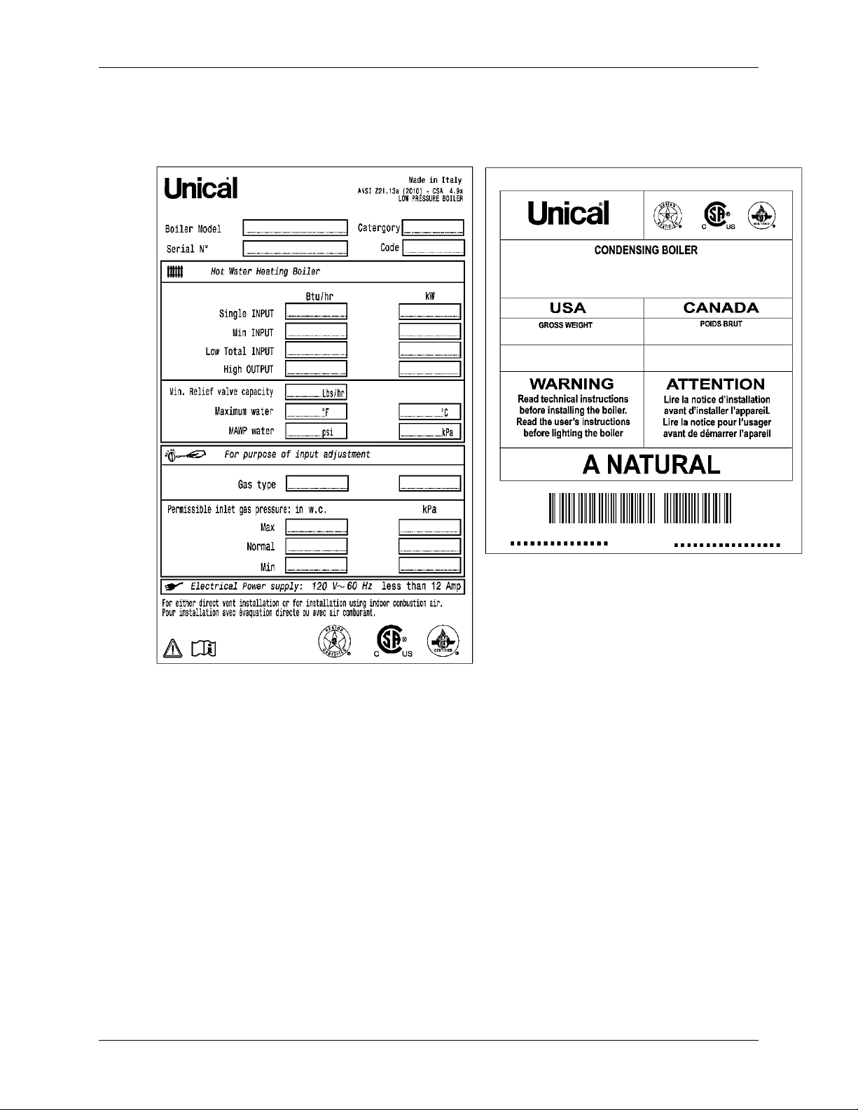
1.7 Data Plate
A sample Data Plate for a MODULEX EXT boiler is shown in the left figure below. A sample of the
Data Packagi ng l abel i s s hown in the right image below.
Figure 1-1: MODULEX EXT Data Plate (L) and Data Packing Label (R)
Eac h unit is fit ted wi th a d ata pl ate, w hich m ay be con sult ed for th e det ails on gas t ype, power
source and vent i ng class ificat ion .
Page 10 of 148 AERCO Int ernational, Inc. • 100 O ritani Dr. • Blauvelt, NY 1091 3 OMM-0087_0E
12/01/14 Phone: 800-526-0288 GF-143
Page 11

MODULEX EXT 321, 481, 641, 802, 962, 1123 BOILERS
Instal lati on, Operation & Maintenan ce Manual
1.8 Operational Requirements
General Requirements 1.8.1
The followi ng instr uc tions MUST be f ol lowed :
• The boi ler mu st only be u sed for its designated purpose as described in these Installation
Instructions.
• Each unit is fitted with a data plate. Consult the details on this plate to verify whether t he boil er
is compliant with its intended location, e.g.: gas type, power source and venting classification.
• On ly use the b oil er with th e ac ces sories and sp are part s l isted.
• Oth er combin ations of accessories and products must only be used i f they are speci fically
designed for the intended application and do not affect the system performance or t h e saf ety
requirements.
• Maintenan ce and repairs must only be performed by trained professionals.
• Installation of a condensing gas boiler must b e approv ed per all fed eral and local gover nment
codes, regulations, and laws.
• Operation of a condensing gas boiler must use a vent system that has been specifically
desig ned and approv ed for this type of b oil er.
• Note that local p ermi ssion and approval f or t he vent s ystem an d condensate water connection
to a pub l ic sewag e system may be required.
Regulatory Requirements 1.8.2
You must also conform to any rules, regulations, or laws concerning the following:
• Local building codes regarding the instal lati on.
• Local building codes concerning the air i ntake and outlet systems and the vent connection.
• Regulations for t he power s upply connec tion.
• Tech nical rules laid down by the gas utility com pany conc erning the c onnecti on of th e gas
connect ion to t he l oc al g as mai ns.
• Instructions and standards concerning the safety equipment for the water/space heating
system.
• Installation instructi ons for building heati ng sy stems.
• The boiler must be located in an area where leakage of the boiler or connections will not result
in damag e to t he are a adj acen t t o the b oiler or to l ower fl oors of th e str uctu re. W hen suc h
loc at ion s c ann ot b e avoi ded, i t i s r ecomm en ded that a su it ab le d rain pan b e in st all ed u nder
the boi ler.
• Do not res tr i ct or seal any air in take or out let openin gs.
• If you find any defects, you must in form t he own er, i n writ ing, of th e syst em def ect and th e
associat ed haz ard.
OMM-0087_0E AERCO International, Inc. • 100 Or itani Dr. • Blau velt, NY 10913 Page 11 of 148
GF-143 Phone: 800-526-0288 12/01/14
Page 12

MODULEX EXT 321, 481, 641, 802, 962, 1123 BOILERS
Instal lati on, Operation & Maintenan ce Manual
WARNING!
Should overheatin g occ ur, or th e gas sup ply fail to s hut off, do n ot
turn off or disconnect the electrical supply to the pump. Instead,
shut of f the g as sup ply at a locati on ext ernal to th e boil er.
Water Quality Requirements 1.8.3
NOTE
For addi tion al i nform ati on conc ern ing w ater quality and treatment,
ref er t o AER CO tec h nical doc um ents Gl yc ol Di rect i ve and AERCO
Piping Application Guide (GF-136-P).
Unsuitable heating system water can cause the formation of scale or sludge, which affects system
efficiency. It can also cause corrosion and reduc e l ife of th e heat exchanger.
• You must follow guidelines for boiler water quality.
• Thoroughly flush the system prior to filling .
• Follow the cleaning instructions.
• Never use water to fill the heating system that has been treated by reverse osmosis,
deionization, or di stilled wat er in or der to soften the water.
• Do not us e i nhi bitors or oth er additives unless approved by AERCO for that purpose.
• When frost protection of the heating system is desired, only use AERCO-approved
antifreezes. The allow ed m aximum concent ration is 50% .
• When using oxygen-permeable pipes, e. g. for under floor heating systems, you must
separate the system fr om the boiler using plate heat exchangers.
• Cl ose t h e v al ves of t h e boiler while flushing the sy st em , do n ot i nt r oduce any sys tem c lean er
into t he boil er loop. Fl ush s ystem t horoughly to remove all system cleaner bef ore f illi ng boiler.
Approve d antif reeze (maxi m u m concentration of 50%):
• Rh omar RhoGard Mutli-Metal (AL safe)
• Noble Noburst AL
Approved system clea ne rs:
• Nob le Noburst Hydr onic Sy stem Cleaner
• Fer nox F3 Cl eaner
• Rhomar Hydro-Solv 9100
Th e sy stem c l eaner s f rom NoB u rst, R hom ar , an d F ern ox ar e NOT t o be u s ed i n t h e b oi l er itself.
Th e b oi ler mu st b e c l os ed of f (v al v es c l os ed) from t h e res t o f t h e sy st em or not c on n ec t ed whi l e
the cleaners are in the system. The system shoul d then be drai ned and then thoroughly flushed
with clean water to remove all the system cleaner.
Approved inhibitors:
• Rhomar Pro-tek 922
• Noble Noburst AL inhibitor
• AERCO/Sentinel products. See list in GF-136-P, section 2.3 - System Flushing,
Treatment, and Cleans ing.
Page 12 of 148 AERCO Int ernational, Inc. • 100 O ritani Dr. • Blauvelt, NY 1091 3 OMM-0087_0E
12/01/14 Phone: 800-526-0288 GF-143
Page 13

MODULEX EXT 321, 481, 641, 802, 962, 1123 BOILERS
•
•
•
•
•
•
•
•
•
Instal lati on, Operation & Maintenan ce Manual
1.9 Tools, Materials, And Additional Equipment
For the installation and maintenance of the boiler you will need:
Standard tools for space heati ng, g as and w ater fitting
Manometer that i s capab le of reading both pos i tive an d negative pr essu res
Combustion an alyzer
Digital multimeter
pH digital meter
Metric Allen wrenches
Metric socket wrenches
1.10 Disposal
Dispose of the boiler packaging in an environmentally sound manner.
Disp ose of comp onent s of t he heating sys tem ( e.g. boiler or c ont rol d ev ice), that mu st b e
rep laced in an env iron mentally responsib le man ner.
1.11 General Warnings
Using the Operation and Maintenance Manual 1.11.1
This instruction manual is an integral and indispensable part of the product and must be
retained by the pers on i n c harge of the applian ce. Please read the instruct ions contained in this
manual carefully as they provide im portant information regarding the s afe installation, use and
servic ing of this appli ance. Keep thi s manual in a s af e pl ace for fu tu re ref erenc e.
Installation and Servi cin g P ers onn el 1.11.2
Installation and servicing must be carried out in accordance with the regulations in force
acc ord ing to t he m anuf act urer ’s i ns tru ct ions and b y l egal ly c omp eten t au thor iz ed pe rs ons. By
defi n i t i on , a comp et en t p e rson i s a p er s on wh o h as a speci f i c t ec h n i c al q ual i f i c at i on i n t h e fiel d
of component s fo r c ent ral heating systems f or domest ic use, domest ic hot w ater producti on, and
servicing. This person must have the qualifications legitimized by the current laws and
reg ulations in for ce.
Inappropriate, incomplete, or irregular servicing could compromise the safe operation of the
app lian ce, an d cou ld cau se inju ry to pers ons, ani mals or damage t o property. The manufacturer
shall not be held li abl e for any su ch in ju ry an d/ or damage.
Any repairs must be carried out by AERCO authorized technicians and using only original spare
par t s. N on -obs erv an c e o f t h e above r eq u i r em ent m ay j eop ard i z e th e s af ety of t h e app l i ance an d
void any warranties.
In the event of failure and/or faulty functioning of the appliance, switch off the boiler. Do not
attempt to make any repairs, but instead contac t qual ified tech ni cians.
To guar ant ee the efficiency and corr ect f unct ion ing of t he appliance it is required th at the b oiler be
serviced annually by a qualifi ed person.
Installation Materials 1.11.3
The installations for the domestic hot water production MUST be built, in their entirety, with
mat erials (t aps, p ipes, fitti ngs , et c.) approv ed f or dri nk able water.
OMM-0087_0E AERCO International, Inc. • 100 Or itani Dr. • Blau velt, NY 10913 Page 13 of 148
GF-143 Phone: 800-526-0288 12/01/14
Page 14

MODULEX EXT 321, 481, 641, 802, 962, 1123 BOILERS
Instal lati on, Operation & Maintenan ce Manual
Preparing Boiler for Servicing 1.11.4
Before carrying out any cleaning or servicing t urn off the electrical supply to the boiler by means
of the ON/OFF switch and/or by means of the appropriate shutdown devices.
Returning a Boiler to Service 1.11.5
Bef ore pu t ti ng a b oil er, w hich has been unused for a length of time, bac k in t o ser vi ce, ri nse t h e
entire d om est ic hot w ater system, allowing the w ater to flow an approp riate amount of tim e in
order to circulate throughout the entire system.
Change in Ow nership 1.11.6
If the ap pliance i s sold or transferred t o another owner, or if t he p resent user mov es from the
installation site and leaves the appliance installed, ensure that the manual stays with the
app li ance so that it c an be c onsulted by the new own er and/or installer.
1.12 Operational Limits of the Boiler
Max. boi ler temperat ure: 180° F
•
Max Al lowable Working Tem peratu re ASME: 2 00 °F
•
• Ma x. Allowable Working Pressure ASME: 92 psi
Page 14 of 148 AERCO Int ernational, Inc. • 100 O ritani Dr. • Blauvelt, NY 1091 3 OMM-0087_0E
12/01/14 Phone: 800-526-0288 GF-143
Page 15

MODULEX EXT 321, 481, 641, 802, 962, 1123 BOILERS
•
Instal lati on, Operation & Maintenan ce Manual
CHAPTER 2: TECHNICAL FEATURES AND DIMENSIONS
2.1 Modulex EX T Technical Features
Com pact, gas fired, L ow N Ox, condensing boiler.
•
Comprised of one sectional boiler bod y, suit abl e as a single boi ler or in a cascaded group.
•
May be instal led i n ei th er an in s ide or outside location.
•
Low inter nal water volume.
•
Fas t r espon se to load variations.
•
Flue exhaust outlet positi onable on three sides.
•
Manifold delivery and return (reversible).
•
Made up of two or more heating elements ( 2 to 7 ), cast alumin um / sil icon / mag nesium.
•
Full range of modulation by variable speed blowers and premix burners.
•
Eac h heat in g el em ent m oni tor s i ts own wat er temperature, and will individually shutdown
•
if f low i s inter rupt ed, w ithout affecting th e oth er burner s ecti ons.
One gas supply line (reversible).
•
• Individual modules capable of between 46 and 160.5 kBTU/hr.
These b oil ers ar e designed f or use with category IV venting.
The boiler is supplied c omplete with all the safety and control devices in accordance with all
current regulations, and its technical and functional features comply with the regulations
prescribed by: ANSI Z21.13 / CSA 4.9 - Gas-fired low pressure steam and hot water boilers.
Temperature Control Devices: 2.1.1
• Local NTC sensor (each heating
element)
• Limit thermostat room (each heating
element)
• Return NTC s ens or (General)
• Safety therm ostat approved (manual
reset)
• Flow sens or B CM
• Flow NTC sensor (General)
Control Panel (E8) Includes: 2.1.2
• ON-OFF switch
• Temperature control / Boiler operation
• Fuses
• Air pressure fans
• Conden sat e level sensor
• Air pr essu re sw i tc h (ant i-obstruction)
• High limit sensors
Other Features Includ e: 2.1.3
• NTC heat sensors for global temperature control on the flow and return.
• 0-10V output to control variable speed pri mary pum p.
• Integral insulation with hypoallergenic synthetic wool.
Premix fiber m esh modulating burner (premixes into the fan with autom atic diaphragm
backflow separation from the co mbust io n chamber).
OMM-0087_0E AERCO International, Inc. • 100 Or itani Dr. • Blau velt, NY 10913 Page 15 of 148
GF-143 Phone: 800-526-0288 12/01/14
Page 16

MODULEX EXT 321, 481, 641, 802, 962, 1123 BOILERS
•
•
•
•
•
•
•
•
•
•
•
•
•
•
•
•
•
Instal lati on, Operation & Maintenan ce Manual
Less th an 49 dBA of noise at maximum power.
Heati ng operati on: instantaneous power microprocessor control, with preset parameters for
com par is on b etw een tem per atu re ( or c alc ulat ed fr om t he e xter nal t em per atur e regu lat i on)
and gl obal temperat ure f low .
Operation modes:
o A bilit y to c ontrol power to the in dividu al heating elements for any calibration with or
without confidential code access.
o Pr oducti on of A.C.S. (Active Cooling System) by NTC sensor of priorities for control by
boiler feed pum p or by three-way divert er valve c ontr oller.
E8 electronic controller included.
BCM ( Boil er Commun i cation M anager) included.
Ability to control power of the individual heating elements.
Con tr ol of heat d eman d: c onstant or rem ote s et poi nt.
Monitoring of oper ating s tat us and temperatu re.
Rep ort in g of alarms .
Setting of parameters.
Em er g enc y oper at i on preven t s t h e boiler from shutting dow n as a r esu l t of th e i nter ruption
of comm unicat ion with a control system or any r emote control un i t .
Alarm management.
Alarm reset input.
Warnin g alarm relay.
Stainless steel condensate collector tank with siphon , drain trap, and smoke chamber.
Easil y r emovabl e st ainl ess steel panels pai nted for outd oor inst al lation.
Built-in air v ent
2.2 General Boiler Operation
The boi ler m ay b e oper at ed fr om t he E8 controller or al ter nat iv ely from a B CM (Boi ler Casc ade
Manager).
The boiler management logi c prov ides t he maximum numb er of simultaneou sly operati ng heating
elements in order to maximize h eat p roduct ion and over all efficiency. Burner efficiency and a high
heat exchange between surfaces con tribute to th e reliab le and eff icient output power. The various
components are designed t o w ork together so that op erati ng ti me is shared equally among the
components, thus reducing maintenance and labor costs.
Th e hot w ater moved by t he pum p is pushed to the return of the p rim ary fl ow of the h ydrau li c
separat or . F r om h er e a sec on d pum p will distribute the hot water to the various destinations. The
cooled return water is drawn by the pump through t he hy draul ic s eparator to r esume the cycle via
the boiler.
WARNING!
If in stalli ng t o an outd oor locat ion wher e fre ezing temperat ures may
occ ur , it is nec essar y t o in st all d evic es an d/ or m ater ial s t o pr even t
any freezing in the condensate drain and the Flow and Return
manifolds. Failure to do so may cause serious damage to the
equipment.
Page 16 of 148 AERCO Int ernational, Inc. • 100 O ritani Dr. • Blauvelt, NY 1091 3 OMM-0087_0E
12/01/14 Phone: 800-526-0288 GF-143
Page 17
MODULEX EXT 321, 481, 641, 802, 962, 1123 BOILERS
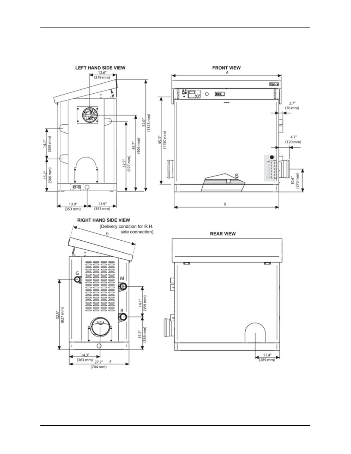
On Modulex EXT models 321,
Instal lati on, Operation & Maintenan ce Manual
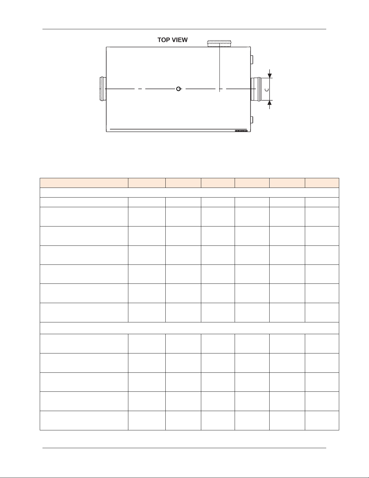
2.3 Dimensional Drawings
642 and 962 the flue terminal
ends inside the casing
OMM-0087_0E AERCO International, Inc. • 100 Or itani Dr. • Blau velt, NY 10913 Page 17 of 148
GF-143 Phone: 800-526-0288 12/01/14
Figure 2-1: MODULEX EXT Dimensional Drawings (Si de V iews)
Page 18
MODULEX EXT 321, 481, 641, 802, 962, 1123 BOILERS
Model
321
481
641
802
962
1123
Dimensions:
No. of Modules
2 3 4 5 6
7
30.0‘‘
30.0‘‘
40.6‘‘
40.6‘‘
51.2‘‘
51.2‘‘
2½‘‘
2½‘‘
2½‘‘
2½‘‘
2½‘‘
2½‘‘
Instal lati on, Operation & Maintenan ce Manual
Figure 2-2: MODULEX EXT Dimensional Drawings (Top View)
Table 2-1: MODULEX EX T Dim ens ion s and Size s
Height (Open) - inches/mm
Height (Closed) - inches/mm
Width ‘’A’’ - inches/mm
Width ‘’B’’ - inches/mm
Dep th ‘’D’’ - inches/mm
Dept h ‘’E’’ - inches/mm
Connections:
Gas - inches/mm
M C/H System Flow
- inches/mm
R C/H System Return
- inches/mm
52.1‘‘
1323
45.3‘‘
1150
764
27.8‘‘
707
30.3‘‘
770
27.7‘‘
704
2‘‘
60.3
76.1
2½‘‘
76.1
52.1‘‘
1323
45.3‘‘
1150
764
27.8‘‘
707
30.3‘‘
770
27.7‘‘
704
2‘‘
60.3
76.1
2½‘‘
76.1
52.1‘‘
1323
45.3‘‘
1150
1032
38.4‘‘
975
30.3‘‘
770
27.7‘‘
704
2‘‘
60.3
76.1
2½‘‘
76.1
52.1‘‘
1323
45.3‘‘
1150
1032
38.4‘‘
975
30.3‘‘
770
27.7‘‘
704
2‘‘
60.3
76.1
2½‘‘
76.1
52.1‘‘
1323
45.3‘‘
1150
1300
48.9‘‘
1243
30.3‘‘
770
27.7‘‘
704
2‘‘
60.3
76.1
2½‘‘
76.1
52.1‘‘
1323
45.3‘‘
1150
1300
48.9‘‘
1243
30.3‘‘
770
27.7‘‘
704
2‘‘
60.3
76.1
2½‘‘
76.1
Vent Conne c t ion ‘’C’’
- inches/mm
Con dens ate d rai n diameter
- inches/mm
Page 18 of 148 AERCO Int ernational, Inc. • 100 O ritani Dr. • Blauvelt, NY 1091 3 OMM-0087_0E
12/01/14 Phone: 800-526-0288 GF-143
5.9‘‘
150
1.57‘‘
40
5.9‘‘
150
1.57‘‘
40
5.9‘‘
150
1.57‘‘
40
5.9‘‘
150
1.57‘‘
40
7.8‘‘
200
1.57‘‘
40
7.8‘‘
200
1.57‘‘
40
Page 19
MODULEX EXT 321, 481, 641, 802, 962, 1123 BOILERS
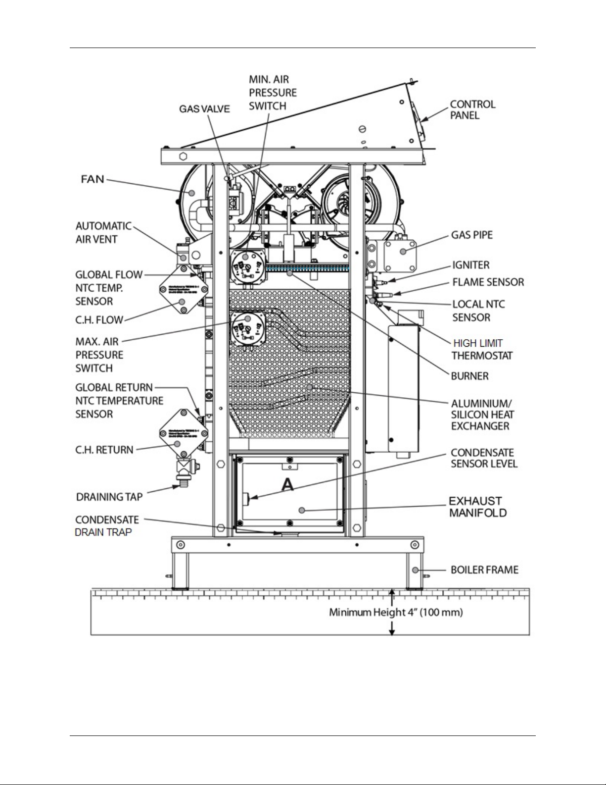
Instal lati on, Operation & Maintenan ce Manual
Figure 2-3a: MODULEX EXT Main Components (Left Side Vie w)
OMM-0087_0E AERCO International, Inc. • 100 Or itani Dr. • Blau velt, NY 10913 Page 19 of 148
GF-143 Phone: 800-526-0288 12/01/14
Page 20
MODULEX EXT 321, 481, 641, 802, 962, 1123 BOILERS
Instal lati on, Operation & Maintenan ce Manual
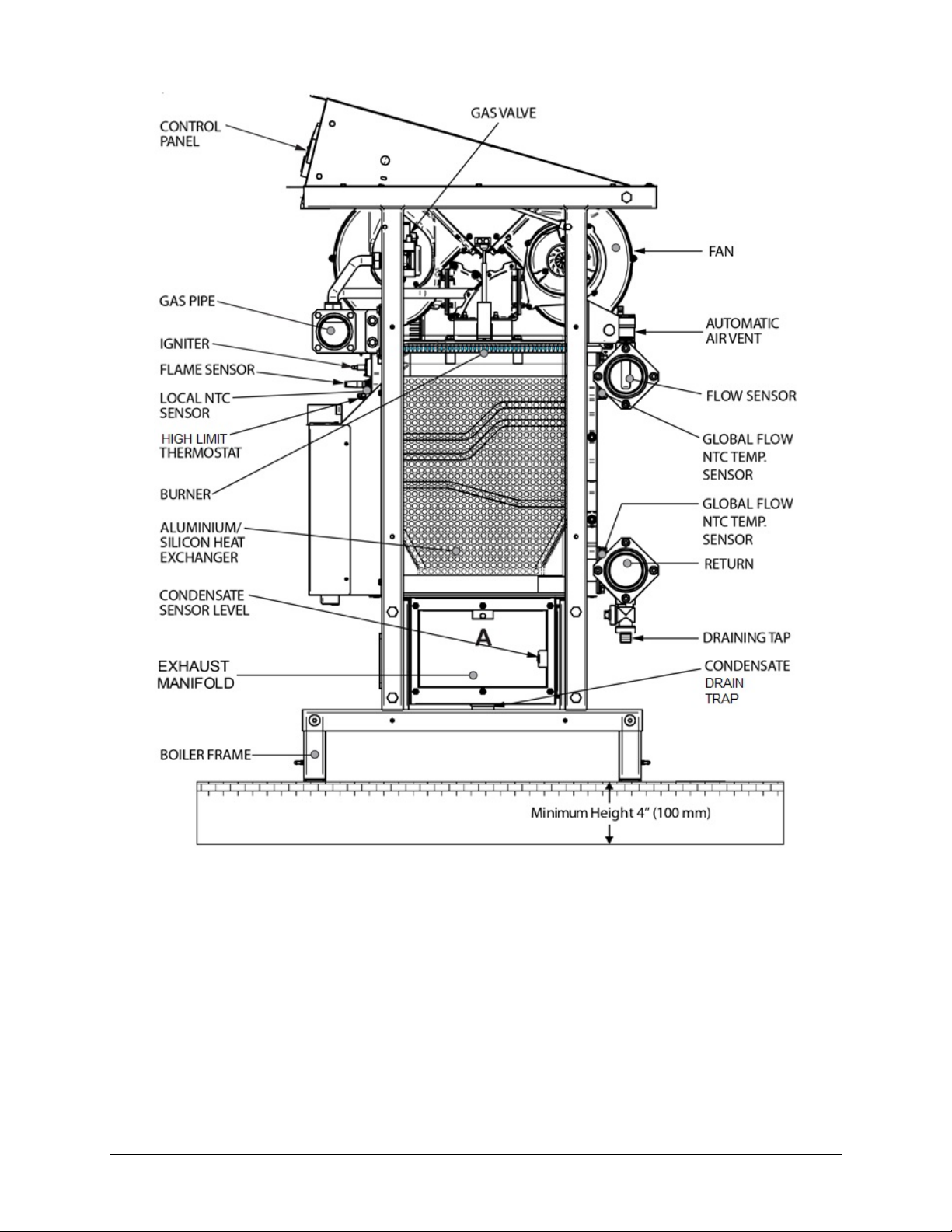
Figure 2-3b: MODULEX EXT Main Components (Right Side View)
• Exhaust and condensate evacuation connections: are on the RIGHT
HAND side (supply condition), but may be moved to the RIGHT HAND or
REAR positions.
• Air intake connect io n : located on th e LE F T HAND side.
• Cold/Hot flow connection: on the RIGHT HAND side (suppl y condition), but
may be moved to the LEFT HAND position.
• Cold /H ot retu rn conn ect ion: on t he RIGHT HAND si de (supply c ondition) ,
but may be moved to the LEFT HAND position.
• Gas connection: on t he R I GHT HA ND s id e (supply condition) , but may be
moved to the LEFT HAND position.
Page 20 of 148 AERCO Int ernational, Inc. • 100 O ritani Dr. • Blauvelt, NY 1091 3 OMM-0087_0E
12/01/14 Phone: 800-526-0288 GF-143
Page 21
MODULEX EXT 321, 481, 641, 802, 962, 1123 BOILERS
Instal lati on, Operation & Maintenan ce Manual
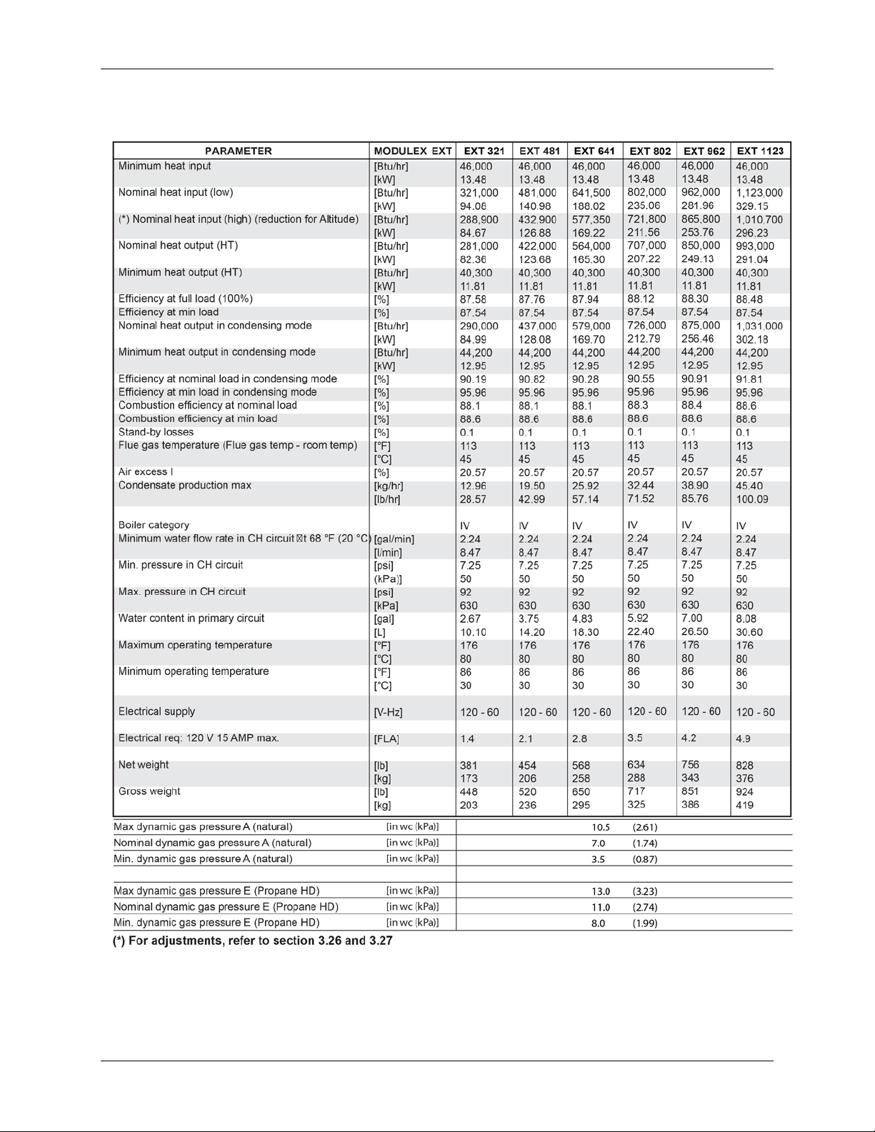
2.4 Per for ma nce Data
Table 2-2: MODULEX EXT Perfor manc e Data
NOTE
The Tec hnical d ata plat e is pl aced u nder the c as in g.
OMM-0087_0E AERCO International, Inc. • 100 Or itani Dr. • Blau velt, NY 10913 Page 21 of 148
GF-143 Phone: 800-526-0288 12/01/14
Page 22

MODULEX EXT 321, 481, 641, 802, 962, 1123 BOILERS
Instal lati on, Operation & Maintenan ce Manual
(This page intentionally blank)
Page 22 of 148 AERCO Int ernational, Inc. • 100 O ritani Dr. • Blauvelt, NY 1091 3 OMM-0087_0E
12/01/14 Phone: 800-526-0288 GF-143
Page 23

MODULEX EXT 321, 481, 641, 802, 962, 1123 BOILERS
Instal lati on, Operation & Maintenan ce Manual
CHAPTER 3: INSTALLATION INSTRUCTIONS
3.1 General Warnings
Appropriate Use of t he Boil er 3.1.1
This boiler MUST be us ed for the use for which it has been exp ressively designed. Any other
use shall b e con sidered impr oper and ther efore dan gerous.
This boiler i s des igned to he at water at a temperature below t he boiling point at atmospheric
pressure.
Prerequisite System Flushing 3.1.2
Before ins tallin g t he boil er th e followin g actions MUST be carried out b y a competent engine er
or tec hnici an:
a) The whole system should be thoroughly flushed in order to remove any
resid ual dirt or grime which could compromise correct boiler operation.
b) Check that the boiler has been preset for operating with the gas type
available. This is verifiable via the indication on the packaging and on the
data badge;
c) Check that the flue pipe has an adequate draft, does not have any
con stri cti ons or ob str uct ions, and t hat no oth er ap pli anc e’s fl ue out let s have
been fitted, unless the flue pipe is serving more t han one heating appliance,
according to the specific standards and regulations in forc e. The connection
between t h e boi l er an d fl u e ou t l et c an be m ad e on l y af t er t hi s ver i f ic at i on has
been car ri ed out .
Installation Personnel Qualifications 3.1.3
The appliance must be installed by a qualifi ed engineer or t ech ni cian, who complies with the
technical requirements, who, under his own respon sibi lity, guarante es the compliance of th e
st an d ar ds ac c ording to t he lates t r egulations.
The app lianc e must be positioned so that at l east the mi nim um op erational and s ervicing
clearances are p rov ided .
The boiler must be connected to a heating system which is compatible to it s performance and
output.
FOR MASSACHUSETTS INSTALLATIONS: The b oil er MUST be i nst all ed by a pl umb er or g as
fitter licensed within the Commonwealth of Massachusetts.
Carbon Monoxide Detector Installation 3.1.4
The instal lati on MUST conf orm to th e requirements of th e aut hori ty having j urisdicti on or, in t he
absence of suc h requiremen ts, to on e of the following:
• United States: Installation must conform to the requirements of the
National Fuel Gas Code, ANSI Z223.1/NFPA 54.
• Canada: Installation must conform to the requirements of CAN/CSA-
B149.1 - Natural Gas and P ropane Inst al lation Code
• Where required by the authority having jurisdiction, the installation must
conform to the Standard ASME CSD-1 Controls and Safety Devices for
Automatically Fired Boile rs.
OMM-0087_0E AERCO International, Inc. • 100 Or itani Dr. • Blau velt, NY 10913 Page 23 of 148
GF-143 Phone: 800-526-0288 12/01/14
Page 24
MODULEX EXT 321, 481, 641, 802, 962, 1123 BOILERS
Instal lati on, Operation & Maintenan ce Manual
3.2 Code and Standards Approvals
The MODULEX EXT boil er has b een reviewed for compli ance w i th the applic abl e sections of
the following North A meri can Standards:
• ANSI Z21.13/CSA 4.9: Gas-fired low press ure s te am and hot wat er boiler s
• ASME SECTION IV: A SME B oil er and P res sur e Ves sel Cod e wi th ad den da, S ect ion IV :
Ru les for Con st ructi on of He ating Boilers
• BTS – 2000: Testing standard method to determine efficiency of commercial space
heating boilers.
• SCAQMD RULE 1146.2: Emissions of oxid es of nitrog en from large wat er he aters and
small boi lers and process h eater s.
• CSD-1: Cont rol s an d saf ety devices for automatic all y gas-fired boiler s.
3.3 Packaging
The MODULEX EXT boiler is delivered assembled and protected by a plastic bag inside a
strong cardboard box and fixed on a p all et. T hi s allows the boi ler to b e handled by a forklift.
CAUTION!
Remove both straps and the cardboard box from above, making
sur e the pr oduct i s intact. The pac king el ements (cardb oard box,
strap s, plastic bag s, et c…) should be kept away from children, as
these present suffocation and choking hazards.
AERCO r ef uses all liability for inju ry to persons , an i mals or damage
to property derived from not respecting the above mentioned
recommendations.
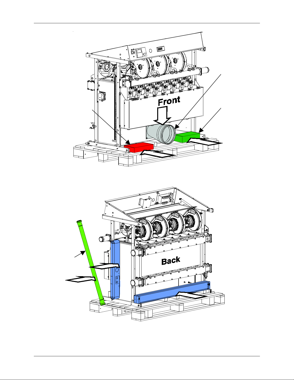
In the packaging, in addition to t he b oiler, you will also find the f ollowing contents (see Fi gures
3-1 and 3-2):
ON THE BOILER FRONT:
• The flue exhaust ter min al scr ewed t o th e fron t of the f rame
• The sealing gasket for flue outlet mounted in the flue assembly.
• A cardboard box containing:
o The sealing gasket for connection between condensate tray and terminal
o 4 elbows + 1 T ee pi ece + 1 plastic plug, Ø 1.6” (40 m m) for condensate drai n.
o the screws necessary for installing the flue exhaust terminal
• External sensors: Remote Temperatur e, D. H.W. storage t ank & O utdoor temperature
Nipple/cap for fl ue exhau st gas sampling tests
•
Resistor kit for emer gency operation
•
Cab le gl ands for electrical supply
•
Pins for mounting soc ket s
•
Kit sheet for output cables 120 / 24 V
•
Page 24 of 148 AERCO Int ernational, Inc. • 100 O ritani Dr. • Blauvelt, NY 1091 3 OMM-0087_0E
12/01/14 Phone: 800-526-0288 GF-143
Page 25

MODULEX EXT 321, 481, 641, 802, 962, 1123 BOILERS
Instal lati on, Operation & Maintenan ce Manual
A cardboard box containing:
•
o
Four (4) frame support feet
o
3 hole covers for swit ching flue exh aust l ocation
o
3 insulation gask ets (f or installat ion out side).
A cardboard box containing:
•
o
CSD-1 header
o
Rel ief valve
ON THE BOILER RIGHT SIDE:
One 39. 3 inch (1 met er) pipe for the con d en s at e evac u at ion system. -
•
Left and right side covers.
•
ON THE BACK OF TH E BOILER
Socket, front and rear.
•
ON THE BOILER T OP :
a plastic bag containing:
•
o
This installation manual for the i nstal ler.
o
User manual for th e user.
o
E8 controller instruction manual.
Pins to hold t he fan assemb ly in a r aised posit ion .
•
IN A SEPARATE BOX
• PVC vent ing starter piece and pipe clamps
• Temperature & Pressure gauge
• Flow S wit ch
• Pi pe adaptor (r ubber )
OMM-0087_0E AERCO International, Inc. • 100 Or itani Dr. • Blau velt, NY 10913 Page 25 of 148
GF-143 Phone: 800-526-0288 12/01/14
Page 26
MODULEX EXT 321, 481, 641, 802, 962, 1123 BOILERS
Cardboard Box
with Parts
Cardboard Box
with Parts
Flue Assembly
And Gasket
Condensate
Drain Pipe
Instal lati on, Operation & Maintenan ce Manual
Figure 3-1: MODULEX EXT Unpacking (Front View)
Page 26 of 148 AERCO Int ernational, Inc. • 100 O ritani Dr. • Blauvelt, NY 1091 3 OMM-0087_0E
12/01/14 Phone: 800-526-0288 GF-143
Figure 3-2: MODULEX EXT Unpacking (Rear View)
Page 27
MODULEX EXT 321, 481, 641, 802, 962, 1123 BOILERS
Instal lati on, Operation & Maintenan ce Manual
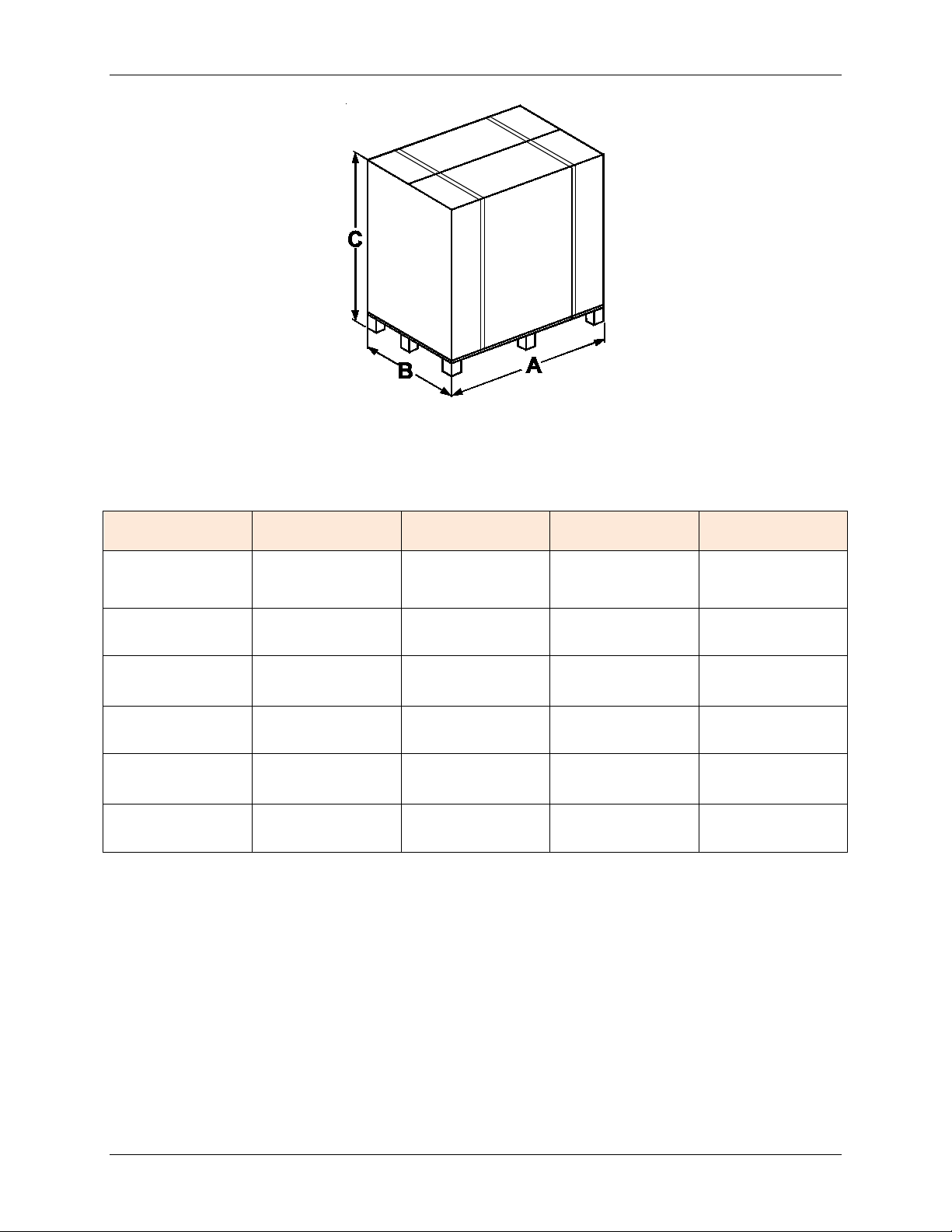
Figure 3-3: MODULEX EXT Shipping Package
Table 3-1: MODULEX EX T Ship pin g P acka ge Dim en sio ns
Model A B C Gross W ei gh t
321
481
641
802
962
1123
43.7‘‘
1110 mm
43.7‘‘
1110 mm
43.7‘‘
1110 mm
43.7‘‘
1110 mm
54.1‘‘
1375 mm
54.1‘‘
1375 mm
35.0‘‘
890 mm
35.0‘‘
890 mm
35.0‘‘
890 mm
35.0‘‘
890 mm
35.0‘‘
890 mm
35.0‘‘
890 mm
49.2‘‘
1250 mm
49.2‘‘
1250 mm
49.2‘‘
1250 mm
49.2‘‘
1250 mm
49.2‘‘
1250 mm
49.2‘‘
1250 mm
448 lb.
203 kg
520 lb.
236 kg
650 lb.
295 kg
716 lb.
325 kg
851 lb.
386 kg
924 lb.
419 kg
3.4 Transporting and Securing the Boiler Safely
The boiler is sus ceptib le to se ri ous damage wh en not s ecu red properly.
• Follow the transportation instructions on the packaging.
• On ly tran sport the boil er us in g appropr iate t ranspor tat ion equipment , such as a hand-truck
wi th a fasten in g belt or sp ecial eq uipment for tran sporti ng heavy eq ui pment.
• When moving t h e b oi l er, it must b e sec u r ed on t h e t r an sp ortat i on eq ui pment t o pr ev ent i t
from fall i ng off.
• Protect all parts against impacts, during transportation.
OMM-0087_0E AERCO International, Inc. • 100 Or itani Dr. • Blau velt, NY 10913 Page 27 of 148
GF-143 Phone: 800-526-0288 12/01/14
Page 28
MODULEX EXT 321, 481, 641, 802, 962, 1123 BOILERS
Instal lati on, Operation & Maintenan ce Manual
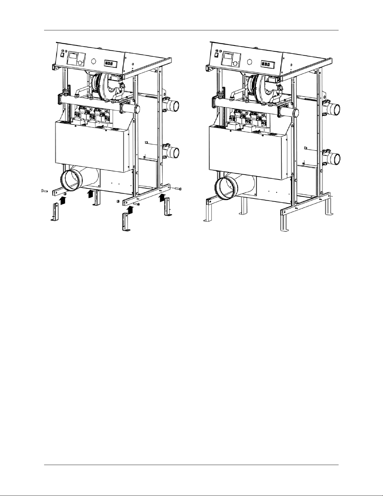
3.5 Removal From Boiler Bed And Insta llation Of Boiler Feet
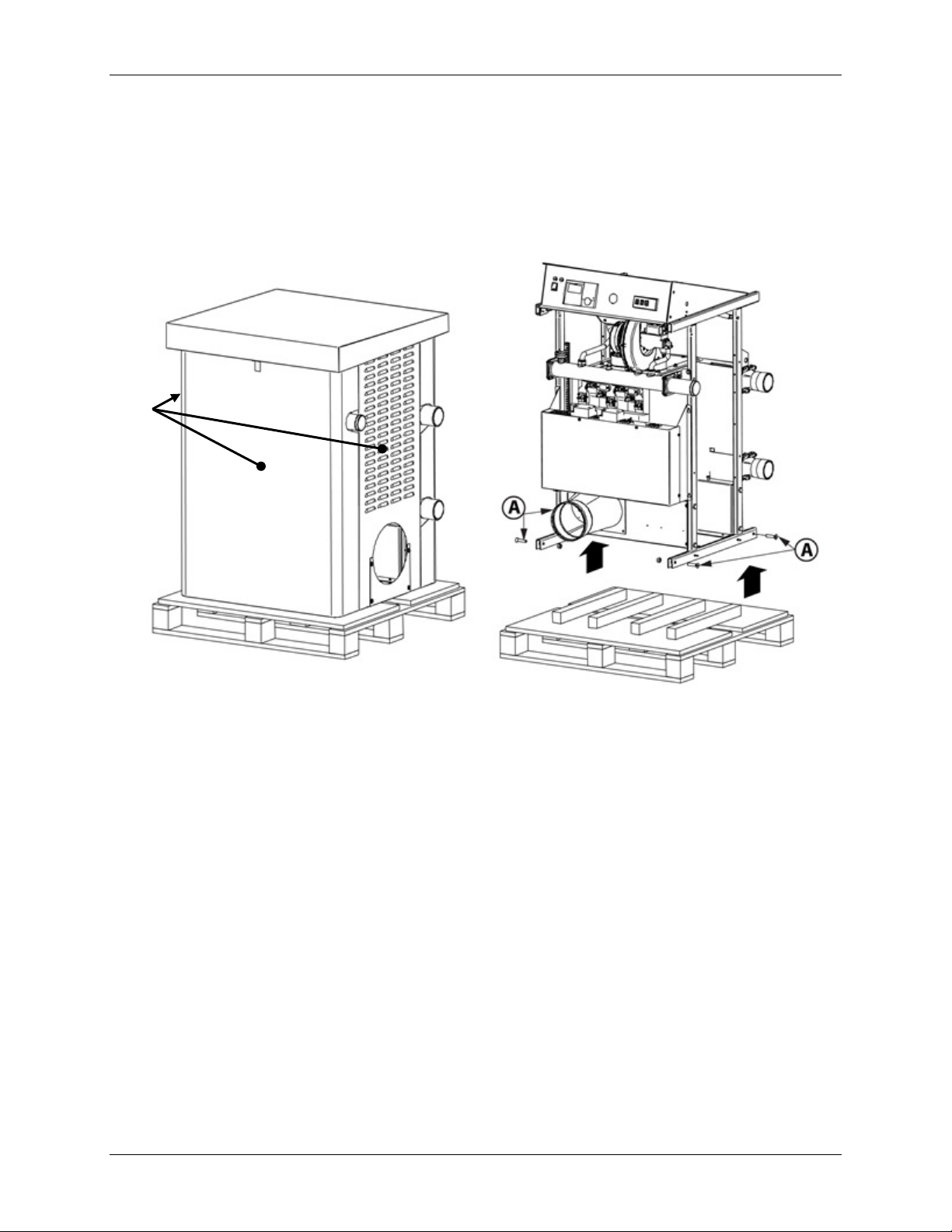
Foll ow the di rec tions below to prepare t he boiler for installation:
1) Remove th e covers of the boiler (Fi gure 3-4).
2) Lift the boiler with a hoist or for klift b ands (F i gure 3-4).
3) Remove th e 4 screws ’’A’’ (Figure 3-4).
Covers
(Remove)
Figure 3-4: EXT Unpacking (Left = With Covers, Right = Lifted Without Covers)
4) Retrieve the four (4) support feet from on e of t he cardboard boxes packaged wi th the
boiler.
5) A tt ach the four (4 ) support feet to t he c hassis using the four ’’A’’ screws removed i n Step
3 (Figure 3-5).
6) P lace the b oiler on concrete slab and re-mount the cover(s) over t he boi ler.
Page 28 of 148 AERCO Int ernational, Inc. • 100 O ritani Dr. • Blauvelt, NY 1091 3 OMM-0087_0E
12/01/14 Phone: 800-526-0288 GF-143
Page 29
MODULEX EXT 321, 481, 641, 802, 962, 1123 BOILERS
Instal lati on, Operation & Maintenan ce Manual
Figure 3-5: MEXT Unpacking (Left = Attach Feet, Right = Ready for Cover)
3.6 Boiler Location Inside A Boiler Room
Sp ec ial att ent i on sh all be p ai d t o l ocal r egu l ati ons and l aw s ab out b oil er enclosures and boiler
rooms, particularly to the m inimum clearances around the boil er. The installation shall be in
compliance with all the latest regulations and laws about boiler enclosures, boiler rooms,
in stal l at i ons of he at i n g and hot -wat er s ys tems , v ent i l ati on , vents c apable of exhausting the flue
gases of condensing boilers, and any other applicable requirements.
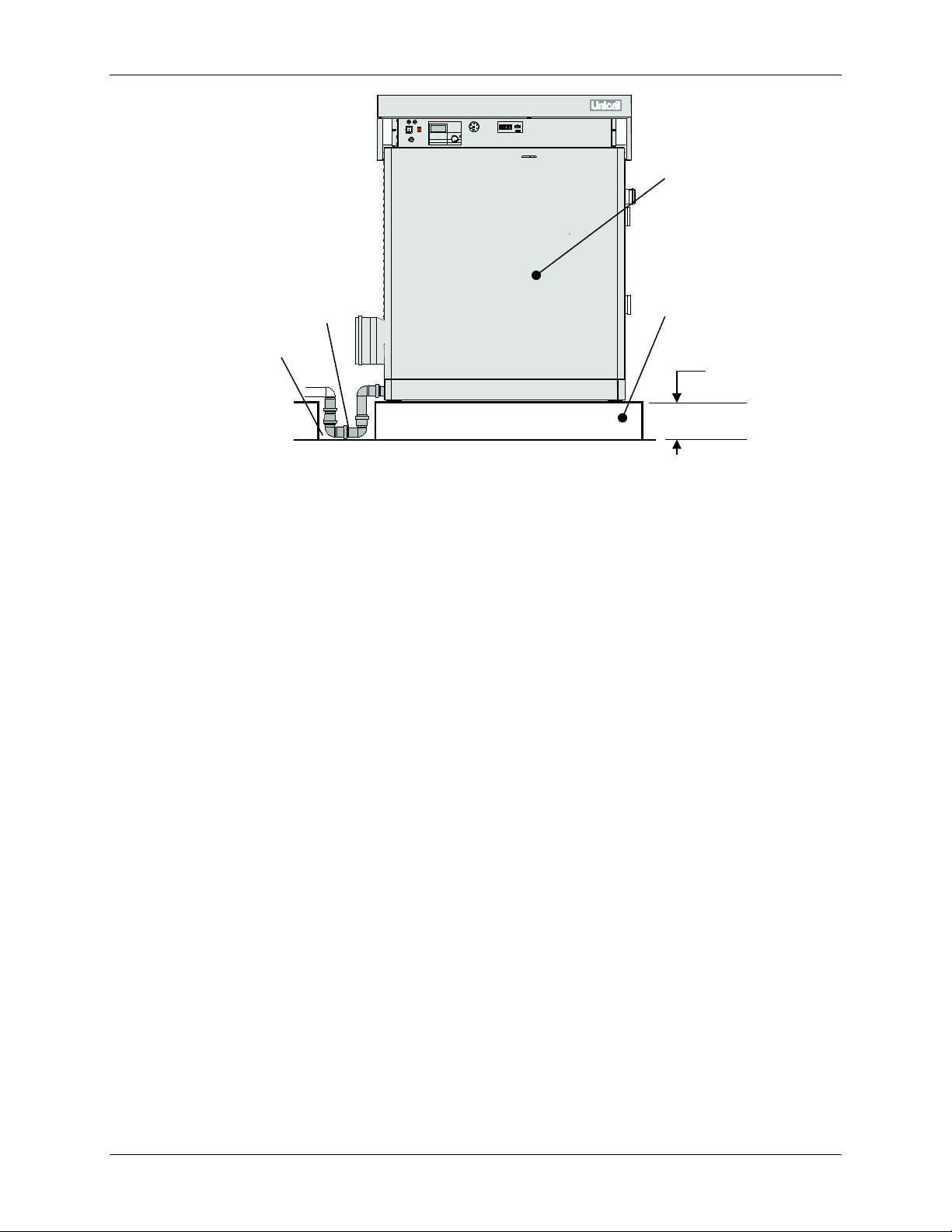
Th e boi ler can be p ut on a flat and suf fic ien tly str ong bas e wi th the same dim ensions as the
boi l er an d at l east 3.93’’ (100 mm) high (see Figure 3-6), in order to assemble the condensate
trap. An alternative to this base m ay be a 100mm deep well or trench next to the boiler to
acc om m odat e t he c ond en s ate “ U” d r ain pi pe (see Figure 3-6). Af ter in st all at ion t he b oil er sh all
be p erfect ly horizontal and stable, to reduce any pos sible vib rations or noises .
OMM-0087_0E AERCO International, Inc. • 100 Or itani Dr. • Blau velt, NY 10913 Page 29 of 148
GF-143 Phone: 800-526-0288 12/01/14
Page 30
MODULEX EXT 321, 481, 641, 802, 962, 1123 BOILERS
Condensate
Drain Pipe
Boiler Housekeeping
Pad (Support Base)
At Least
3.93” (100mm)
MODUL EX EX T
Boiler Front
Instal lati on, Operation & Maintenan ce Manual
Well or Trench
for Condensate
Drain Pipe
Figure 3-6: Boiler (Front View) on Housekeeping Pad with Condensate Drain Pipe
Boiler Room Safety Concerns 3.6.1
When selecting the position for t he inst allat ion of t he b oiler pleas e com ply with the f ollow ing
safety requirements:
• Ensure easy access to the component s of th e boiler to f acil itat e maint enance.
• The ro om where t he boi ler will be placed mus t always be frost free.
Do n ot s tore or use g as ol i n e o r ot h er f l am mabl e v ap or s an d l i q u i d s i n t h e vicinity of this
•
or an y ot h er app l i an c e.
Never use or store any chlorinated detergents or halogenated hydrocarbons (e.g. in
•
spraycans, solvents and detergents, paints, adhesives) in proximit y to the boiler .
For outd oor in stallati on see Warning for Outdoor installation on page 16.
•
Products to Avoid in the Boiler Room 3.6.2
Do NO T st ore the fol low ing p roducts in the b oiler room and/or around com busti on air int ake
vents.
• Spray cans containing chlorocarbons/ fluorocarbons
• Am moni um an d/ or am moni um sol ut ion s
• Permanent wave sol ut ion s
• Chlor inated wa xes and/or cleaners
• Chlorinated swimmi ng pool chemi cals
• Cal cium chl oride used f or t hawing
• Sodium chloride used for water sof tening
• Refrigerant leaks
• Paint or varnish remover s
Page 30 of 148 AERCO Int ernational, Inc. • 100 O ritani Dr. • Blauvelt, NY 1091 3 OMM-0087_0E
12/01/14 Phone: 800-526-0288 GF-143
Page 31

MODULEX EXT 321, 481, 641, 802, 962, 1123 BOILERS
Instal lati on, Operation & Maintenan ce Manual
• Hydroch lori c acid/ muri atic aci d
• Cements and glues
• Antistatic fabric sof ten ers u sed in cloth es dr yers
• Chlorine-type ble aches, detergents , an d cleani ng solv ent s
• Adhesives used to fasten building products
• other damaging or flammable products
3.7 Recommended Clearances for Servicing
Recommended c l ear ances ar ound the boiler are listed below (see Figure 3-7):
TOP of the boi l er : 24‘‘ ( 600 mm)
FRONT of the boiler: 24’’ (600 mm)
RIGHT side: 24’’ ( 600 mm)
LEFT side: 24’’ (600 mm)
FLOOR/GROUND: 4’’ (100 mm)
BACK of the boiler: 24’’ (600 mm)
Figure 3-7: EXT Boiler Clearances
It is recommended to provide the boiler with the clearances as shown in the drawing in order to be
able t o perform normal ser vice and cleaning operat ions. M inimum required clearances depend on
the piping and venting configuration. For further details, contact your loal manufacturer’s
representative.
OMM-0087_0E AERCO International, Inc. • 100 Or itani Dr. • Blau velt, NY 10913 Page 31 of 148
GF-143 Phone: 800-526-0288 12/01/14
Page 32

MODULEX EXT 321, 481, 641, 802, 962, 1123 BOILERS
3-9.
Instal lati on, Operation & Maintenan ce Manual
3.8 Boiler Connections
At del i very , the MODULEX EXT boiler is setup with al l c on nec t ion s, (i.e. c ol d/ hot w ater f low &
return, gas, and exhaust outlet) on it s RIGHT HAND side.
Changing Exhaust Outlet Location 3.8.1
To move the flue exhaust outlet terminal from the RIGHT HAND side (standard delivery
posi ti on ) to th e REAR posit ion, it is necessary to request t he Rear Exhaust kit (P/N 00364937),
which includ es a cover for closing off the RIGHT HAND side panel exhaust opening (see Figure
3-9).
Rear flue
manifold ki t
includes the
cover for the
right-hand
exhaust h ole.
See Figure
Figure 3-8: Rear Exhaust Kit (P/N 00364937) for Changing Exhaust Outlet from RIGHT
HAND side to REAR on
EXT 802, 962, 1123 (only)
Page 32 of 148 AERCO Int ernational, Inc. • 100 O ritani Dr. • Blauvelt, NY 1091 3 OMM-0087_0E
12/01/14 Phone: 800-526-0288 GF-143
Page 33

MODULEX EXT 321, 481, 641, 802, 962, 1123 BOILERS
Opening Cover
Sup ply Gas to
Connector
NOTE
Tor que al l bolts to 8 .8 5 ft-lbs (12 N/m)
Instal lati on, Operation & Maintenan ce Manual
Exhaust
Figure 3-9: Rear Exhaust Kit (P/N 00364937) for Changing Exhaust Outlet from RIGHT
HAND side to REAR
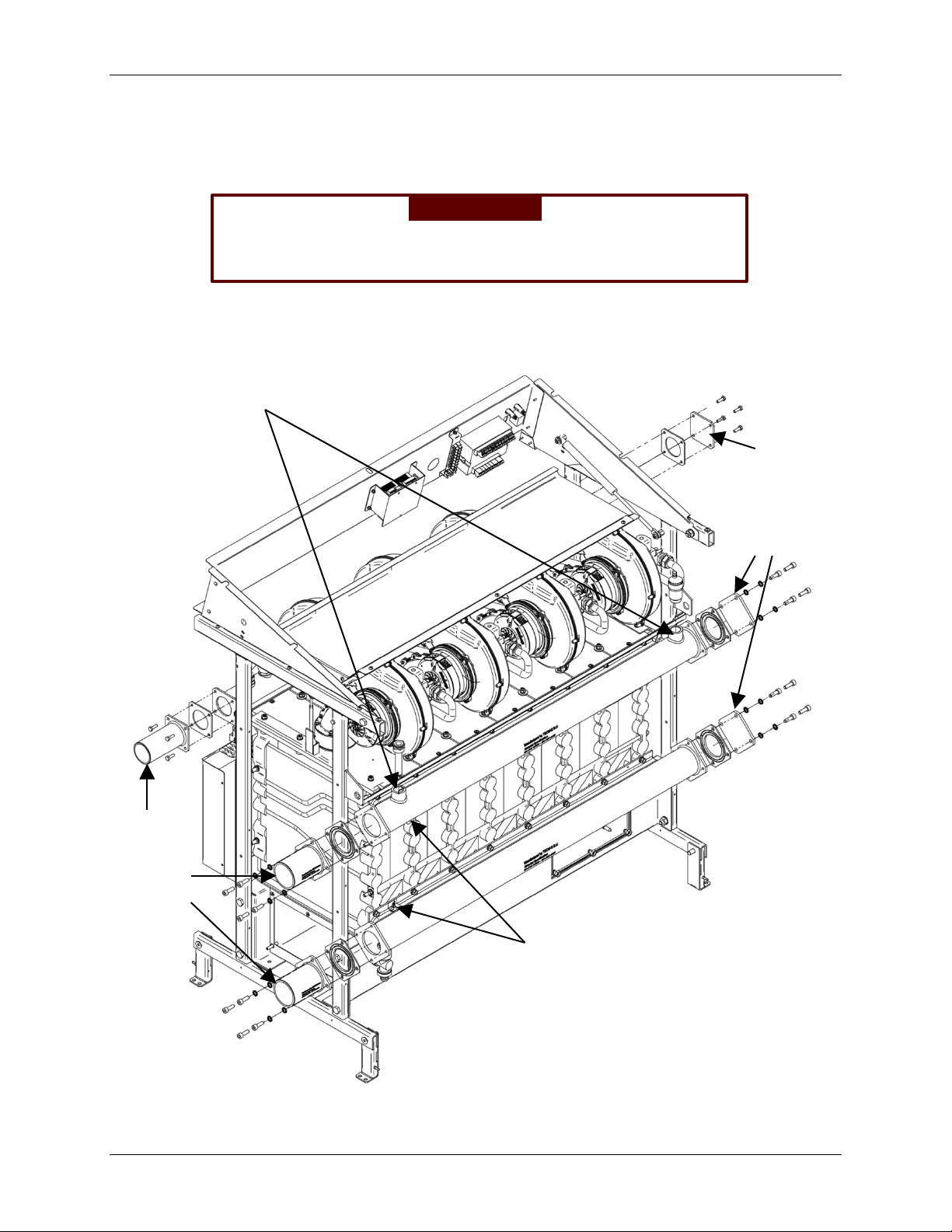
Reversing Gas Manifold Connections 3.8.2
To move th e gas connect ion from the RIGHT HAND side (standard d eli very posit ion ) to the LEFT
HAND side, swap the end plate and the gas supply connector screwed onto the gas manifold
ends as shown in Figure 3-10. Ensure t hat the gaskets for ALL con nec tion s ar e rev ers ed alon g
with the connectors themselves.
Gas Manifold
Gasket
Gas Manifold
Gasket
Gas Manifold
End Plate
Gas Manifold
Figure 3-10: Reversing Gas Connections from RIGHT HAND to LEFT HAND
OMM-0087_0E AERCO International, Inc. • 100 Or itani Dr. • Blau velt, NY 10913 Page 33 of 148
GF-143 Phone: 800-526-0288 12/01/14
Page 34
MODULEX EXT 321, 481, 641, 802, 962, 1123 BOILERS
Reverse positions
NOTE
Torque all bolts to 8.85 ft-lbs (12 N/m)
Instal lati on, Operation & Maintenan ce Manual
Reversing Cold/Hot Water Flow & Return Connections 3.8.3
Change of Water Flow and Return connections from RIGHT hand to LEFT hand requires
reversing connectors, moving the Flow and Return Temperture Sensors to other end, and
exchanging posit ion s of th e Boiler Sensor KF an d A utomatic Air Vent.
WARNING!
En sure that the gaskets for AL L connection s are rev ersed along
with the connectors themselves.
3.8.3.1 Reversing Cold/Hot Water Flow & Return Piping Connectors
Re fer to Figure 3-11 and reverse the connectors and end caps on Supply, Flow, and Return
pipes . Ensur e that all gas kets are also reversed.
of Boiler Sensor
KF and Automatic
Air Vent. See
Figure 3-13.
Move
end caps (and
gaskets) to other
end of
Flow/Return
pipes.
Move supply
connectors
(and
gaskets) to
other end of
Flow/Return
pipes.
Move Flow and Return
Sensors to other end of
pipes. See Figure 3-12.
Figure 3-11: Reversing Cold/Hot Water Flow and Return Connections and
Page 34 of 148 AERCO Int ernational, Inc. • 100 O ritani Dr. • Blauvelt, NY 1091 3 OMM-0087_0E
12/01/14 Phone: 800-526-0288 GF-143
Sensors from RIGHT HAND to LEFT HAND
Page 35

MODULEX EXT 321, 481, 641, 802, 962, 1123 BOILERS
Sensor cable unplugged
bracket, and screw
Instal lati on, Operation & Maintenan ce Manual
3.8.3.2 Reversing Flow & Return Temperature Sensors
On e sen sor is loc at ed on t op of th e l ow er Return pipe railing, wh il e th e oth er one i s l oc ate d
under the upper Flow pipe railing. Move these two sensors to other end of Flow/Return
pipes.
C.H. Flow Sens or is installed s ame as
Return Sensor, except under Return
pipe.
Sensor Cable Plugged
into Sensor
showing sensor, sensor
Figure 3-12: Reversing Flow and Return Temperature Sensors
3.8.3.3 Reversing Boiler Sensor Kf And Automatic Air Vent
Rev erse the posit ions of th e B oiler Sens or KF and A utom atic Air Vent l ocat ed on t he top
Flow pipe.
Figure 3-13: Reversing Boiler Sensor KF with Automatic Air Vent
OMM-0087_0E AERCO International, Inc. • 100 Or itani Dr. • Blau velt, NY 10913 Page 35 of 148
GF-143 Phone: 800-526-0288 12/01/14
NOTE
When reversing hydraulic and gas pipe connections, you must
close up the chassis openings vacated after the change. See
Figure 3-14.
Page 36

MODULEX EXT 321, 481, 641, 802, 962, 1123 BOILERS
Instal lati on, Operation & Maintenan ce Manual
Figure 3-14: Caps and Plugs Used for Closing Up Vacated Gas and Hydraulic
Connection Openings
3.9 Gas Connection General Info rm at io n
For natural gas connections, refer to section 3.9.1. For propane gas connections, refer to
section 3.9.2.
Th e g as s upp l y con n ect i on mu st c omp l y wit h loc al r egul at i on s or, i f suc h r egu l at i ons do n ot exi st ,
wi th th e National Fuel Gas Code, ANSI Z223.1/NFPA 54.
For Can ad a, t h e g as c on n ec ti on m u st com pl y wi th l oc al r eg ulati on s or , i f suc h r egul ati on s d o n ot
exist, with the CAN/CSA-B149.1 - Nat ural Gas and Pr opane In stal lation Code.
Bef ore i nst al li ng th e boi ler it is rec omm end ed that all th e sup ply pipi ng b e thor oug hl y cl eaned in
ord er t o remove any residual grime which could compromise the boilers correct functioning.
As a safety measure against gas leaks, AERCO recommends installing a surveillance and
protective sy s t em m ade u p of a g as l e akage det ec tor combined with an on-off sol en oi d v alv e on
the gas supply line.
The bo ile r a nd its indivi dual shutoff valve must be disco nne c ted f ro m the gas supply piping system
du ring any pres sur e testin g of that sys tem at test pres sures in excess of 1/2 PSI (3. 5kPa).
The boiler must be isolat ed from the gas supply piping system by closing its individual manual
shutoff val ve during any pressure testing of the gas suppl y piping syst em at test pressures equal
to or less than 1/ 2 PSI (3. 5 kPa) .
Page 36 of 148 AERCO Int ernational, Inc. • 100 O ritani Dr. • Blauvelt, NY 1091 3 OMM-0087_0E
12/01/14 Phone: 800-526-0288 GF-143
Page 37

MODULEX EXT 321, 481, 641, 802, 962, 1123 BOILERS
Instal lati on, Operation & Maintenan ce Manual
WARNING!
• THE GAS CONNECTION MUST BE INSTALLED BY A
REG ISTE RED ENGI NEER W HO MUST COMPLY WITH THE
REGULATIONS I N FORCE AND TO THE REQUIREMENTS
INDICATED BY THE LOCAL GAS SUPPLIER. AN
INCORRECT INSTALLATION CAN CAUSE INJURY OR
DEATH TO PERSONS, ANIMALS OR DAMAGE TO
PROPERTY. THE MANUFACTURER SHALL NOT BE HELD
LIABLE FOR ANY INJURY AND/OR DAMAGE DUE TO
INAPPROPRIATE INSTALLATION.
• Do n ot u se t he boi l er for anot her typ e of g as t han i ndic at ed on
the identification plate of the boiler. This will cause improper
functioning and can damage the boiler.
• Al w ays ch ec k th e s af et y of t h e g as p i pe s ys t em b y m eans of a
soap bubble test using a leak-searc h spray.
Natural Gas Connections 3.9.1
3.9.1.1 Natural Gas Piping Sizes
Contact your local gas supplier f or natur al gas pipe sizes and meter types.
3.9.1.2 Natural Gas Piping Connections
Th e b oil er g as pi pe i s equ ip ped w it h e xter nal 2” M-NPT thread, onto which t he tail piece of
the gas sh ut off valve c an be con nected . Use appropr iate sealing.
The connection to the boiler must include a suitable method of disconnection and a gas
control valve mus t b e in st all ed adjacent to the boi ler for isolati on purposes .
3.9.1.3 Natural Gas Supply Pressure Requirements
The nominal inlet working gas pressure m eas u r ed at t h e b oi ler shou l d be 7 ” W. C . (18 mbar)
for Natural Gas (Gas A). Maximum pressure with no flow (lockup) or with the boiler running is
10.5 inches W.C. Minimum pressure wit h the gas fl owing (verify during boiler startup) is 4.0
inches W.C.
Propane Gas Connections 3.9.2
3.9.2.1 Propane Gas Pipin g Si zes
Contact your local gas supplier for Propane gas pipe sizes, tanks, and 100% lockup gas
pr ess ure r egulator.
3.9.2.2 Propane Gas Pipin g C onne ctions
Use a gas s hut off v alve c ompati ble wi th propane gase s.
•
A sediment trap must be installed ups tr eam of th e gas con trol s.
•
The boiler pipe is provided with an external 2” MNPT t h r ead, on t o w h i c h t he t ai l p iec e of t h e
gas shut off valve c an be s crew ed. Use app ropriate se ali ng.
The c onnecti on t o th e boi ler mu st inc lude a suitable method of disconnection.
The nominal inlet working gas pressure measured at the boil er should be 11” W.C. (27 mbar)
for P ropane gas (Gas E).
OMM-0087_0E AERCO International, Inc. • 100 Or itani Dr. • Blau velt, NY 10913 Page 37 of 148
GF-143 Phone: 800-526-0288 12/01/14
Page 38

MODULEX EXT 321, 481, 641, 802, 962, 1123 BOILERS
Instal lati on, Operation & Maintenan ce Manual
A gas control valve must be i nstal led adjacent to t he boiler for isol ation pu rposes.
3.9.2.3 Propane Gas Supply Pressure Requirements
Pressures requi red at gas v alve i nlet pres su re port:
Nominal gas pressure – 11 inches W.C.
•
Maximum gas pres sure – 13 inc hes W.C. with no flow (lockup) or with boiler running.
•
Minimum gas pressure – 8 i nch es W. C. wi th g as flow in g (verify during boiler startup).
•
NOTE
Ensur e th at th e high gas pr essu re regulator is in st all ed at least 6 to
10 f eet upstream of th e boil er.
3.10 Flow And Return Pipe Connections
The cold and hot water flow and return circuits must be connected to the boiler via the
respective 2½” M and R connections as indicated in Table 2-1.
W hen det ermining the size of the c old /h ot w ater circuit pi pes it is essential to bear in m ind the
pressur e loss es induc ed by any of th e system’s component s and by the configuration of the
system.
When planning the routing o f the col d/ hot water piping, take th e necessary precauti ons to avoid
air t raps and p ockets and to facilitate the continuous purging of the system.
WARNING!
• Before installing the boiler we recomm end that the system is
flushed out with a suitable cleaning pr oduct in order to elimi nate
any metallic tool in g or w el di ng r es i du es, or oi l and g rime, which
cou ld reach the boiler and affec t the prop er functioning of the
boiler.
• Ensure that the system piping is NOT used for eart h grounding
of electrical or telephone systems. Such grounding of system
piping is unsuitable and can cause serious damage to the
piping, b oiler, and radi ator s.
• It i s ab s olu t el y for b i dd en t o fi t on -off valves in the piping before
the required saftey d evices.
3.11 Pressure Relief Valve
The included p r es su r e r el i e f v al v e (Figur e 3-17) m u s t be f i t t ed on t h e CSD-1 manifold, which is
in st all ed on th e flow pi pe p er instructi ons in the next s ection, 3.12, bel ow . I t complies with t he
ANSI/ASME
Boilers’’), and C S A B5 1 , Boiler, Press ure v ess el, and P res sure Pi pi ng C ode, as appli cable.
The boiler ships with an 80 psi pressure relief valv e for inst allation into the CSD-1 m anifol d
he ader. Lower s ys tem pres s ures will requir e lower rated press ure r elief valv es (not supplied ).
Page 38 of 148 AERCO Int ernational, Inc. • 100 O ritani Dr. • Blauvelt, NY 1091 3 OMM-0087_0E
12/01/14 Phone: 800-526-0288 GF-143
ANSI Z21.13 / CSA 4.9
Boiler and Pressure Vessel Code, Section IV (‘’Heating
Page 39
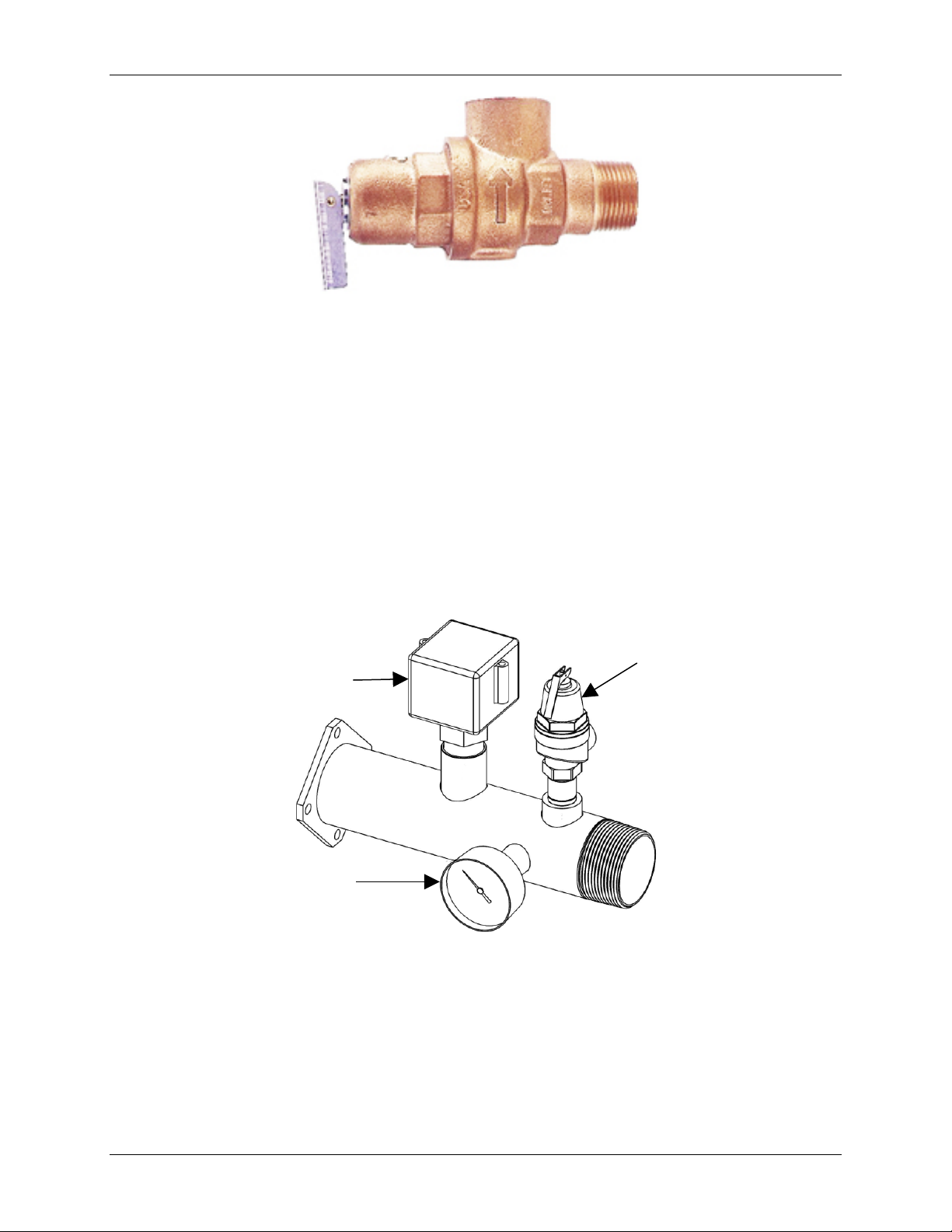
MODULEX EXT 321, 481, 641, 802, 962, 1123 BOILERS
Flow S wi tch
3/4” Pressure Relief
Instal lati on, Operation & Maintenan ce Manual
Figure 3-17: Pressure Relief Valve
3.12 CSD-1 Manifold Assembly (Supplied)
Th e ins tall at ion of a f low sw itch , pr essur e/ tem perat ur e gau ge, and an AS ME c omp lian t saf ety
pressure relief valve designed for the boiler output capacity are required. These major
components are supplied w ith t he boiler and must be assembl ed and wired when inst alling t he
boiler at the s ite. Th e man ifold assembly components s uppl ied are:
• 3/4” P ressure Relief Valve (Fi gur e 3-17)
• Flow Switch
• Pres sur e/Temperature Ga uge
The pressure relief valve and ot her manifold components are shown in Figure 3-15.
Valve
Pressure/Temperature
Gauge
Figure 3-15: Manifold Assembly and Components
To install the pressure relief valve and the other components shown, proceed as shown in
instructions below.
OMM-0087_0E AERCO International, Inc. • 100 Or itani Dr. • Blau velt, NY 10913 Page 39 of 148
GF-143 Phone: 800-526-0288 12/01/14
NOTE
Use T ef l on t ap e or a sui t ab le p ip e j oi nt com pou nd for com p onen t
and piping connections described in the following steps. Refer to
Figure 5 for component ident ificat ion.
Page 40

MODULEX EXT 321, 481, 641, 802, 962, 1123 BOILERS
Instal lati on, Operation & Maintenan ce Manual
Installing the Pressure Relief Valve and Other Components
1. At tach man ifold to the out let supp ly connecti on on th e boil er via th e f langed connec tions .
2. Cu t t h e flow s w i t c h for 2 -1/2” pipe, as dir ected in th e fl ow switc h paddle p ac k ag i n g. F or
installations expecting less than a 10 gpm flow, the switch must be adjusted as follows:
a) W i t h no f l ow , t ur n ad j us tmen t s c r ew on t h e swi t c h c oun t er -clockwise until the switch
trips.
b) Then turn screw 1/2 turn clock-wis e and cont inue i nstal lation.
3. Connec t the foll owing com ponents to t he tapp ed holes in t he man ifold ass embl y (see
Figure 3-15):
• 3/4” P ressure Relief Valve
• Flow Switch
• Press ure/Temper atur e Gauge
4. Check t o ensure th at all c omponents ar e securely ti ghtened and that the fl ow switch
paddle moves freel y w i thout int erference.
5. L ocate th e BMM mod ule, w i th the “F L” label, at the unit front (F igure 3-16) and remove
the black j um per wir e from the t erminals of th e connect or sh own in t he det ail of Fig ure
6. Conn ect th e two fl ow swit ch wi res to th e two t erminal s. Flow switc h wires h ave n o
polarity, so c an be in sert ed without regard to posit ion.
Remove t his black j ump er and
ins er t the two wires from the flow
switch into termin al connector.
Figure 3-16: BMM Location and Flow Switch Connection
3.13 Determination of Primary Boiler Pump Or Boiler System Pump
The following table gives an indication of the pump’s flow rate in function of the ∆t of the
pr i mary circui t if the i nstal lati on has a mixing head er.
The size of the pumps m ust be determined by installers or technical engineers according to
boiler data an d system design.
Page 40 of 148 AERCO Int ernational, Inc. • 100 O ritani Dr. • Blauvelt, NY 1091 3 OMM-0087_0E
12/01/14 Phone: 800-526-0288 GF-143
Page 41

MODULEX EXT 321, 481, 641, 802, 962, 1123 BOILERS
Instal lati on, Operation & Maintenan ce Manual
Table 3-2: MODULEX EXT Minimum/Maximum Flow Rates
Boiler Model 321 481 641 802 962 1123
Min. flow rate demanded in gal/min ∆T 27°F (15°C) 2.5 2.5 2.5 2.5 2.5 2.5
Min. flow rate demanded in gal/min ∆T 36°F (20°C) 1.9
1.9
1.9 1.9 1.9 1.9
Max flow rate demanded in gal/min ∆T 27°F (15°C) 24.5 36.8 49.2 61.7 74.2 86.8
Max flow rate demanded in gal/min ∆T 36°F (20°C)
18.4 27.6 36.9 46.3 55.6 65.1
The w ater side resistance c urv e of the boiler is shown in the diagram in Figure 3-18.
The pu mp is not an i nt egral part of t he boiler. It i s recommended to choose a pump with the rate
and del ivery h ead at about 2/ 3 of it s ch arac teristic heating c urve.
Figure 3-18: MODULEX EXT Water Side Pressure Losses
Th e u se of a m ixi n g header f itt ed between th e boiler circui t an d the
system circu it is always advisable. It becomes INDISPENSABLE i f
th e syst em req uir es flow rates super ior t o the maxim um permit ted
boiler flow r ates, which is to say lowe r than 27° F (15 K) .
NOTE
OMM-0087_0E AERCO International, Inc. • 100 Or itani Dr. • Blau velt, NY 10913 Page 41 of 148
GF-143 Phone: 800-526-0288 12/01/14
Page 42

MODULEX EXT 321, 481, 641, 802, 962, 1123 BOILERS
Instal lati on, Operation & Maintenan ce Manual
3.14 Condensate Piping and Drain
To av oid con dens ate collecting inside the combustion exhaust syst em, the condenate piping
must have an inclination t oward the drai n of at leas t 3/ 8 in./ft (30 mm/m).
The liquid c olumn, inside the condensate siphon, (see Condensate Siphon P lug in Figure 3-19)
ne eds t o b e fi l led w ith water after installation. The m inimum height of th e w at er in t he c olu m n,
w hen all th e fans are in operat ion, must be at least 2 5 mm (1 i n. ).
In order to avoid ice for mation whi le the b oiler is ope rating, which can cause the boiler to stop
functioning, the entire condensate evacuation system must be well insulated. N ote that it is
forbidden to evacuate the c ondensate through an open gut ter to pr event the ri sk of i ce f orm i ng
and avoid exposur e of the corrosiv e cond ensat e to the external environment.
The condensate must be neutralized before being evacuated to the sewer, which can be
achieved by mixing the condensate with lime or with drain water coming from washing
machines, dish washing mach in es, etc., w hich normal ly has a base pH.
Th e conn ect ion t o th e sew er w ill be t hroug h a closed, but visibl e drain. Given the high acidity
(pH 3 to 5) of th e c on d en s ate, only plasti c mater ial may b e u s ed f or t he co n den s ate ev ac u at i on
pipes. Moreover it must be dimensioned and constructed s o as to all ow th e c orr ec t out -flow to
the drain, preventin g any b ottleneck and any leakage.
Consult local codes regarding condensate neutralization. Neutralization may be obtained by
mixing it with the buildings drain water or with limestone, which normally has a base pH.
AE RCO offer s a c ondensate neut ralizing ki t and a n eutalizing tank for prep aring condensate
w as te for safe evacuation in to a sew er system.
Figure 3-19: MODULEX EXT Condensate Piping
The outl et o f t he c ondensate drain pipe exits from the right sid e of the boi ler, just bel ow th e
RIGHT-SID E flue outlet opening.
IMPORTANT NOTE
If it is not p oss i bl e t o use a 4’’ (101mm) bas e or h ou s ek eep i n g p ad
on which to place the boiler, install the boiler on the floor and
pr ovide a well or trough (mini mum of 4’’ - 101 mm deep) in which to
lodge t he U of the con densat e pipin g. See F i gure 3-19.
WARNING!
Bef ore com m i s sion i n g th e boi l er, f ill t he con densat e dr ai n pi pe with
water, at the dedicated filling -up plug. See Figure 3-19.
Page 42 of 148 AERCO Int ernational, Inc. • 100 O ritani Dr. • Blauvelt, NY 1091 3 OMM-0087_0E
12/01/14 Phone: 800-526-0288 GF-143
Page 43

MODULEX EXT 321, 481, 641, 802, 962, 1123 BOILERS
Instal lati on, Operation & Maintenan ce Manual
WARNING!
Do not install the condensate drain where freezing may occur.
Use m at eri al s app roved by the au th ori ty havi ng j uri sdic ti on i n you r ar ea. In the absence of such
authority, PVC and CPVC pipe m ust com ply with AST M D1785 , F441 or D2665. Cem ent and
primer mus t comply with ASTM D2564 or F493.
For Canada, use ULC certified PVC or CPVC pipe, fittin g s and cement.
Periodic cleaning of the condensate disposal system must be carried out.
3.15 Water Treatment
The c hemical /phy sical composition of the heating sy s tem’s water is fundam ent al for th e boil er’s
correc t op eration and sa fety.
Among the problems c aused by poor qualit y of feed wat er, th e most frequent and the most
serious is the buildup of deposits on boiler th ermal exc hange s urf aces .
Less f requent, but al so s erious, are d epos its on the water circ ulating piping surfaces. Because
of t he low thermal conduct ivity of mineralizat ion des posits cau sed by i mproperly tr eated water ,
the thermal exchange effic ien cy may be seriously red uc ed, and can result in ver y d angerous
localized overheating.
AERCO suggests treating and conditioning feed water for the heating circuit in the following
cases:
• W hen the hardness of the water is higher than 9 grains (15°f).
• For cold/ hot water installations with large water con tent .
• Renewal of the water system due to u ncont rolled leakages.
• Subs equent r efill in g of the sy st em due to mai nt enance work on the inst all ation.
• Pres ence of diff erent metals in th e water circuit.
Properly treat ed system and f eed water wil l eliminate or substantially reduce th e followin g
problems:
• lime scale depos it
• corrosion sludge
• deposits
• microbiological growths (mold s, bacter ia etc.)
An appropriate treat ment of the s uppl y water wil l preven t the above s tated problems and wil l
maint ain the correct operation and efficiency of the boiler ove r time.
In order to properly t reat water for use in a hydronic boiler heating system, the following
physical/chemical characteristics must be addressed.
Water Hardness: If water hardnes s is ov er 6 to 9 grains, a wat er s oftener mu st be used.
Sediment: If s ediment is pres ent in th e sys tem, a sediment f ilter or oth er app ropriate devic e,
must be used.
Water pH: If w ater has a pH above 8, or below 5, then the wat er m ust be tre ated to prov id e a
medium pH of between 5 and 8.
The syst em wat er to b e ju dged f or water characteristi cs should be tak en fro m the return pipe of
the primar y c ircuit downstream of the c irculating pump.
OMM-0087_0E AERCO International, Inc. • 100 Or itani Dr. • Blau velt, NY 10913 Page 43 of 148
GF-143 Phone: 800-526-0288 12/01/14
Page 44

MODULEX EXT 321, 481, 641, 802, 962, 1123 BOILERS
NOTE
Instal lati on, Operation & Maintenan ce Manual
3.16 Important Installation Warnings
Oxygen Levels in the System Water Warning 3.16.1
All n eces sary precautions must be taken for preventing the formation and localization of oxygen
in the system’s water. For this reason, ensur e that the plastic piping used in under-floor heating
sys tems is im permeable to ox ygen.
Antifreeze Compatibility Warning 3.16.2
If any ant i-fre eze sol utions ar e used ens ure that t hey are comp atible with alumi num and any
other boiler component s and materials.
Lime Scale and Corrosive Water Damage Warning 3.16.3
Any d amage caused to the boil er due to the formation of lime s cale or by cor rosive water will not
be cover ed by t he warran ty. Ap propriate steps must be taken to ensur e th e i ndirect tank water
heater does not become plugged by scale caused by hard water or sedim ent. If the indirect tank
w ater heater becomes plugged by eit her s cali ng f rom hard wat er or sed iment it is not the
respons ib ility of AERCO I nter nat ion al.
Connection to Refrigeration System Warning 3.16.4
The boiler, wh en us ed i n conn ection w ith a refrigeration sy stem, mu st b e installed so t he c hi ll ed
medium is pip ed in parallel wit h t he boiler with approp riate v alves to preven t t he c hi lled medium
from enter in g t he boiler.
The boiler pi ping system of a hot wat er boiler con nected to heati ng coil s loc ated in ai r H andling
un its w here th ey may b e exposed to refrigerated air ci rc ul ation must b e equi pped w ith flow
contr ol valves or oth er automatic m eans to p reven t g ravity ci rcu lation of th e boil er w ater du ri ng
the cooling cycl e.
3.17 Air Intake Connection
Instal l air intake as s hown in Fi gure 3-20. For air in take connection pip in g use onl y:
• Ø 4’’ PVC Pipes Schedule 40/80 for Modulex EXT 321, EXT 481, EXT 641
• Ø 6’’ PVC Pipes Schedule 40/80 for Modulex EXT 802, EXT 962, EXT 1123
Use silicon e to
lubricate the internal
surface of the seals
befor e assem bling.
Figure 3-20: MODULEX EXT Air Intake Connection
3.18 Flue Manifold Conn ecti on
Page 44 of 148 AERCO Int ernational, Inc. • 100 O ritani Dr. • Blauvelt, NY 1091 3 OMM-0087_0E
12/01/14 Phone: 800-526-0288 GF-143
Page 45

MODULEX EXT 321, 481, 641, 802, 962, 1123 BOILERS
NUTS (6)
RECTANGULAR
FLUE MANIFOLD
Instal lati on, Operation & Maintenan ce Manual
To assemb le the f lue manifol d to t he boiler flue exh aust open ing, retrieve th e six (6 ) nut s and
washers from the plastic bag, shipped with the boiler, and affix to the boiler opening per Figure
3-21. The Manifol d may be installed on th e left , front, or rear. If switc hing to left or rear pos itions,
the unused outlet should be cover ed with the plate and gasket removed f rom outlet being used.
GASKET
GASKET
FLUE MANIFOLD
Figure 3-21: Connection of Flue Manifold To Boiler Exhaust Opening
For venting systems in the USA, it is neces sary to assem ble the Euro-to-USA adaptor to the flue manifol d
as shown in Figure 3-22.
GASKET
The gas ket may seem l ar ge.
It i s intentionally des ign ed to
NOTE
provide a tight fit.
EUROPEAN-TO-USA
FLUE ADAPTER
Figure 3-22: Assembly of USA-to-European Flue Adaptor to Flue Manifold
OMM-0087_0E AERCO International, Inc. • 100 Or itani Dr. • Blau velt, NY 10913 Page 45 of 148
GF-143 Phone: 800-526-0288 12/01/14
Page 46

MODULEX EXT 321, 481, 641, 802, 962, 1123 BOILERS
Instal lati on, Operation & Maintenan ce Manual
3.19 Flue Exhaust Piping to Vent
In a condensing boiler, the flue exhaust is evacu ated at a very low temperature (maxi mum of
about 183°F - 84°C). Thus, it is necessary that the chimney be impermeble to t he c ondensate of
the combustion products and is made of corros ion resistan t mater ial s.
The different joint s must be wel l sealed and equip ped w ith suitab le g ask ets in order to prevent
the escape of condensate and prevent the ingress of air.
To determin e the pr oper cros s s ection an d height dimensions of the flue exhaust piping, it is
necess ary to make ref erenc e to nation al an d local rules.
In order to preven t the f ormati on of ic e du ring th e operation, the temp erat ure o f the int ernal wall
of t he flue exhaust syst em should not be below 32 °F (0 °C) throughout its length.
For efficient venting of the combustion exhaust and to address condensation due to lower
external temperatures, ensure t hat c ombusti on condensation is discharged into the boil er
condensate tray or into another separate collection pan accord in g t o th e in st all ation.
A test nipple, for measuring combusti on gases, should be installed onto the first t hree feet of t he
exhaust m ani fold flue. To do th is, a hole wit h a di ameter of 0.83‘‘is drilled in a convenient
location for testing and the test nipple hardware assembled to the flue pipe as shown in Figure
3-23, below.
Figure 3-23: Installation of Test Nipple into Flue Manifold Piping
NOTE
Dam age cau sed by mis takes in in st allati on, failure t o complete t he
instructions as w ri t ten , or the im proper use of the flue system are
not t he resp onsibi li ty of the supplier.
3.20 Vent Starter Pieces
Table 3-3 lists the vent starter pieces. See Figure 3-25 for an illustration of a fully assembled kit.
PVC star ter pi eces are in cluded with ever y unit. Stai nl ess steel starter pieces may by purc has ed
from AE RCO or directly from the ven t manufact urer.
Page 46 of 148 AERCO Int ernational, Inc. • 100 O ritani Dr. • Blauvelt, NY 1091 3 OMM-0087_0E
12/01/14 Phone: 800-526-0288 GF-143
Page 47

MODULEX EXT 321, 481, 641, 802, 962, 1123 BOILERS
Instal lati on, Operation & Maintenan ce Manual
Table 3-3: Start er Pi ec es
Boiler Models Diameter Material Kit Part Number
Stainless Steel Contact vent manuf actu rer direc tly
EXT321, 481, 641 4” Diameter
EXT 802, 962, 1123 6” Diameter
Polypropylene Contact vent man ufacturer d ir ectl y
PVC P/N 49051 (included)
Stainless Steel Contact vent manuf actu rer direc tly
Polypropylene Contact vent man ufacturer d ir ectl y
PVC P/N 49050 (included)
Eu r opean to
American
Standard Flue
Adapter
Figure 3-24: Flue Exhaust Diameter Reduction Adaptor Kit and Parts
The flue venting pipe is affixed to the adapter using RTV liquid silicone and then clamped with a
worm-dri v en Hose C lamp.
W hen using non-metall ic (plast ic) ven ting m ater ials, use Schedule 40 or thicker, Single-wall,
uninsulated pipes. When using non-metallic (plasti c) v ent sys tems for C anadian in stallat ions,
OMM-0087_0E AERCO International, Inc. • 100 Or itani Dr. • Blau velt, NY 10913 Page 47 of 148
GF-143 Phone: 800-526-0288 12/01/14
Page 48

MODULEX EXT 321, 481, 641, 802, 962, 1123 BOILERS
HOSE CLAMP.
FLUE VENT PIPE
ADAPTER ASSEMBLY
Instal lati on, Operation & Maintenan ce Manual
per CSA B149.1, use v ent syst ems t hat are certified to the s tan dard f or Type BH Gas Ven ting
Systems, ULC-S636.
The plasti c c ompon ent s, primers and glues of the cer tified vent s ystem mu st be fr om a si ngle
sys tem man ufactur er and not mixed with other manuf acturer’s vent syst em parts.
The Inspection Port should be pl ugged wi t h an appropriate plug (not inc l uded).
Tes t N ip ple
should be
INSTAL FLUE PIPING
TO ADA PTER WITH
RTV LIQUID
SILICONE AND
WORM-DRIVEN
installed
wit h in first
3 feet of
flue start.
See Figure
3-23.
EUROPEAN TO AMERICAN
STANDARD FLUE
ADAPTER
Figure 3-25: Installed Flue Exhaust Diameter Reduction Adaptor Kit
3.21 Combustion Air and Ventilation Openings
Pr ovi s ion s for c omb u st i on an d ven t i i at i on ai r mu s t b e m ade i n ac c or d an c e w ith section 5.3, A ir
for Combustion and Ventilation, of the National Flue Gas Code, ANSI Z223.1/ NFPA 54., or
Sections 7.2, 7.3 or 7.4 of CAN/CSA-B149.1-05, installation cod es, or app i l c ab l e prov isions of
the local building codes.
Insufficient Ventilations and Combustion Air 3.21.1
BOILER DAMAGE AND OPERATIONAL FAILURES may occu r due to insufficient or im proper
op eni ngs for combust ion air and/or ven til ation of the boil er r oom.
Provisions for combustion air and ventilation are alway s required, regard less of whet her th e
combu sti on ai r is t aken from the outsid e (s ealed combus tion) or inside (roo m air used as
combustion air).
Insufficient ventilation of the boiler room can lead to h ig h air t emperatures. Thi s can resu lt i n
boiler damage. Note t he f ollowing:
• Make su re t hat intake and exhaust openings are su fficien tl y sized and no reduction or closure of
any openings takes place.
• When a combustion air or ventil ation problem is not resolved , do not operate the boiler.
• Please note these r estrictions and its dangers to the operator of the boiler.
Wh en one exp ects contaminated combus tion air (near s wimming pool s, chemical cleani ng
operations, hair s alons, etc.), sealed combus tion operation is recommended.
Page 48 of 148 AERCO Int ernational, Inc. • 100 O ritani Dr. • Blauvelt, NY 1091 3 OMM-0087_0E
12/01/14 Phone: 800-526-0288 GF-143
Page 49

MODULEX EXT 321, 481, 641, 802, 962, 1123 BOILERS
Instal lati on, Operation & Maintenan ce Manual
WARNING!
Fire danger due to flammable materials or liquids. Do not store
flammable materials and liquids in the immediate vicinity of the
boiler.
See Section 3.6.2 for war nin gs and gu id el in es concer ni ng mater ials
and contaniments that should be avoided in the boiler room and
near air inlets when operating the boiler.
Room Air Combustion 3.21.2
The boiler closet or ro om shall be provided with two permanent openings com m un ic at i ng di r ect l y
wi th an additional room(s). T he t otal in put of all gas ut ilizati on equipment in st all ed i n the combined
space shall be considered in making this determination. Each openin g sh al l h ave a minimum free
are a of 1 squ are inch per 1,000 Btu per hour of tot al input rat ing of all gas utiliza tion equ ipme nt in
the confined space, but no less than 100 square inches. One opening shall comm ence within 12
inches (305 mm) of the top, and on e opening shall comm ence wit hin 12 inches (305 mm) of the
bot t om of t h e encl os ur e. Th e mi n im um dimension of air openings shall not be less than 4 inches
(101.6 mm).
Sealed Combustion 3.21.3
The boiler closet or room shall be provided with two permanent openings, one commencing within
12 i nch es (305 mm) from the t op of t he encl osur e, and one c omm encing within 12 inc hes (30 5
mm) from the bot tom of the enc los ure. Th e openin gs shal l comm unicate direct ly, or b y duc ts, with
th e out door s or s pac es ( cr awl or att ic ) t h at fr eel y c om m uni c at e w i t h th e ou t d oor s. Th e mini m um
dimension of air openings s hal l be no l ess t han 4 inches (101.6 mm).
1. Where directly communicating with the outdoors, each openi ng shall have a minimum free
area of 1 square inch per 4,000 Btu/hr of total input rating of all equipment in the
enclosure.
2. W here c om mu ni cati ng wi t h th e outdoor s t hrough ver t i cal d uct s, each opening shall have a
minimum free area of 1 square inch per 4,000 B tu/hr o f tota l input rating of all equipment in
the enclosur e.
3. Where communicating with the outdoors through horizontal ducts, each opening shall
have a minimum free area of 1 square inch per 2,000 Btu/hr of total input rating of all
equipment in the enc losure.
4. W her e d uct s ar e us ed , t h ey s hal l b e of th e s ame cr oss -sec t i onal ar ea as t h e f r ee ar e a o f
the opening to which they connect.
3.22 Installation of the Exhaust and Air Intake System
NOTE
Consult local and state codes pertaining to special building code
and fire department requirements. Adhere to national code
requirements.
NOTE
Observe the listed maximum lengths of vent system, which are
dependent on b oil er m od el. The m axi m um p ermi s sibl e len gt hs are
OMM-0087_0E AERCO International, Inc. • 100 Or itani Dr. • Blau velt, NY 10913 Page 49 of 148
GF-143 Phone: 800-526-0288 12/01/14
Page 50

MODULEX EXT 321, 481, 641, 802, 962, 1123 BOILERS
Instal lati on, Operation & Maintenan ce Manual
listed in secti on 3.2 3, below.
Minimum clearance of 4 ft . (1.22m ) horizont all y fr om , an d in no cas e abov e or below, unl ess a 4 f t
(1 . 22 m ) h or i zon t al di st anc e i s m ai nt ai n ed, fr om el ectr ic m et ers, g as m et ers, reg u l at or s an d r el i ef
equipment.
The mi nimum dist ance f rom adjacent pub l i c w alkways , ad jacent build ings, op enable wi ndows an d
building openings shall not be less than t hose val ues sp eci fied in th e Nation al Fu el Gas Code,
ANI Z 223.1 / NFPA 54 and/ or the Natural Gas and Pr opabne I nst allati on Code C AN/CSA B 149.1.
Do not extend exposed vent pipe outside the building beyond recommended distance.
Con dens ate cou ld freeze an d block vent pipe.
Ven t s hou ld t erm inat e at l east 3 ft (9 15 mm) aw ay from adjac ent w alls, insid e c orners and 5 ft.
(1 525 mm ) bel ow roof ov erhang (see Fi gure 3-26).
It is not r ecomm en ded t o t erm in ate v ent ab ove an y door or window, as c onden sate c an fr eeze
causing ice formations.
Do not use a c him ney as a rac eway i f an other boil er or fir eplac e is vent ed i nto or thr ough the
chimney.
Figure 3-26: Minimum Distances of Exhaust Opening and Building Features
Important Factors for Terminal Orientation and Location 3.22.1
Ter minals sh oul d be pos itioned so as to avoid produ cts of c ombustion from entering openings
into the buildi ngs or other vents.
The terminal sh oul d be located where d ispersal of comb usti on products is not impeded and with
due regar d f or t he damage or discoloration that might occur to building surfaces in the vicinity.
In cer tain weather condit ion s c ondensati on may also ac cumul ate on th e outs ide of th e air in let
pipe. Such conditions must be considered and where necess ary insulation of th e inlet pip e may
be required. In cold and/or humid weat her water vapor m ay condense when leaving the vent
termi nal . The ef fect of suc h condens ation must b e con sidered. The ter minal mu s t be locat ed in
a place n ot likely t o cau se a nuisance.
Maintain 12” of clearanc e abov e the highest antic ip ated snow level or grad e or w hichever is
gr eater . Please refer to you r local cod es for th e sn ow level i n your area.
Page 50 of 148 AERCO Int ernational, Inc. • 100 O ritani Dr. • Blauvelt, NY 1091 3 OMM-0087_0E
12/01/14 Phone: 800-526-0288 GF-143
Page 51

MODULEX EXT 321, 481, 641, 802, 962, 1123 BOILERS
Max. Vent Equiv.
Examples 1 & 2
Max. Vent Equiv.
Examples 3 & 4
EXT 481
4” (101 mm)
EXT 641
4” (101 mm)
EXT 802
EXT 962
Sharp 90°
Feet (m)
Maximum
Feet (Meters)
Instal lati on, Operation & Maintenan ce Manual
The w hol e rout e of t he vent system must be installed upwards and never complet ely nor part ly
downwards.
Minimum and Maximum Wall Thickness 3.22.2
The label at right, which is placed on the unit,
indicates t he minimum and m aximum wall t hickn ess
through which venting is allowed to penetrate
horizontally. Howev er, i f ven ting is vertical, t hen t here
is no minimum wall thickness.
3.23 Vent Pipe Sizing
The maximum length is the combined length of straight horizontal and vertical runs, and the
equivalent st raight l ength of fittings. The required length s f or each boi ler are as follows:
NOTE
The ex ampl es referenced in th e tab le below are on th e next p age.
Table 3-4: Modulex EXT Vent and Pip i ng Di am et er Char t
Model
EXT 321
EXT 1123
Model
EXT 321
EXT 481
EXT 641
EXT 802
EXT 962
EXT 1123
No. of
Modules
2 4” (101 mm) 100 ft. (30 m) 6 + 6 (1.8 + 1.8 )
3
4
5 6” (152 mm) 100 ft. (30 m) 6 + 6 (1.8 + 1.8 )
6 6” (152 mm) 100 ft. (30 m) 6 + 6 (1. 8 + 1.8)
7 6” (152 mm) 100 ft. (30 m) 6 + 6 (1.8 + 1.8)
Vent Diameter
Inches (mm)
Feet (M)
100 ft. (30 m) 6 + 6 (1.8 + 1.8 )
100 ft. (30 m) 6 + 6 (1.8 + 1.8 )
Table 3-5: Modulex EXT Vent and Piping Length Chart
Vent
Pipe
Diameter
4”
(101 mm)
6”
(152 mm)
Elbow
Equivalent
10 Feet
(3 m)
10 Feet
(3 m)
Sweep 90° Elbow
Equivalent
Feet (m)
5 Feet
(1.5 m)
5 Feet
(1.5 m)
45° Elbow
Equivalent
Feet (m)
5 Feet
(1.5 m)
5 Feet
(1.5 m)
Feet (M)
Length
Equivalent
100 Feet
(30 m)
100 Feet
(30 m)
NOTE: The maximum pressure drop of the combus t ion air piping is als o 100 equivalent f eet (30 m ).
OMM-0087_0E AERCO International, Inc. • 100 Or itani Dr. • Blau velt, NY 10913 Page 51 of 148
GF-143 Phone: 800-526-0288 12/01/14
NOTE
The flue system must be installed in accordance wit h the l oc al an d
national Standards.
Page 52

MODULEX EXT 321, 481, 641, 802, 962, 1123 BOILERS
Instal lati on, Operation & Maintenan ce Manual
Example 1:
A 40 foot (12.2 m ) length of vent pip e and 1 sharp 90° elbow add up to 40 ft. + 10 ft. = 50
equ ivalent f t. (17. 4 m).
Example 2:
A 30 foot (10.4 m) l ength of vent pipe and 2 sharp 90° elbows add up to 30 ft. + (2 x 10 ft.) =
50 equivalent ft. (17.4 m).
Page 52 of 148 AERCO Int ernational, Inc. • 100 O ritani Dr. • Blauvelt, NY 1091 3 OMM-0087_0E
12/01/14 Phone: 800-526-0288 GF-143
Page 53

MODULEX EXT 321, 481, 641, 802, 962, 1123 BOILERS
•
•
•
•
Instal lati on, Operation & Maintenan ce Manual
Figure 3-27: Modulex EXT Allow ab le Ve ntin g Solution s
3.24 Electrical Connections
Regulations in Force 3.24.1
The electr ical connect ions to t he boiler m ust be m ade in ac cord ance wi th all applic able l ocal
codes and the l atest rev ision of t he National Electrical Code, ANSI/NFPA-70.
Instal lati ons s hould also c onform with CSA C22.1 Canadian E lectrical Code Part 1 , if installed in
Canada.
WARNING!
The boi ler mu st be elect rically grounded in accor dance wi th loc al
codes, or in absence of local codes, with the National Electrical
Code, ANSI/ INFPA 70 and/or the CSA C22.1, Electrical Code.
The gas, D.H.W. (Domestic Hot W ater), and C/H system pipes
must NEVER be used for elec t rical g rounding.
Ensure that the above safety electrical requirements are instituted. If in doubt, ask a
pr of essionall y qualified tech nician to check the appli ance’s electrical system.
AERCO does not accept responsibility for any damages arising from failure to correctly
electrically ground t he boil er.
It is necess ar y t h at a q u al i f i ed t ec h n i c i an v er i f y t hat t h e el ect r i c al s ys tem i s ad eq u at e t o satisfy
the app lian ce’s maximum pow er requirements, in dicated on t he data p late, verify in g i n particular
that the c ables are su itable for the appli ance’s maximum power use.
CAUTION!
For the ap pli anc e’s g eneral el ec tric al su pply , t he u se of adapt ors,
multipl e s ock ets, and/or extension cords i s strictly forbidden.
The use of any power supply equi pment im pl i es th e ob s er van c e of
several fu ndamen tal rules, such as :
Do not touch the appliance with any wet part of your body
and/or while barefooted.
Do not pull the supply cables.
Do not expose the boiler to sunlight, rain, etc., unless it is
explicitly prepared and inst all ed for such use.
Do n ot permit children or inexpert peopl e to u se the ap pli ance.
Mains Electrical Supply Connection (120 V – 6 0 Hz ) 3.24.2
Mains electrical requirements call for a 120V, 60 Hz power source. The electric power
connections to the junction box of the boile r are shown in Figure 3-29.
Th e p ow er su p ply t o t he b oi l er , 1 20 V AC - 60 Hz single phase, must be made in t he JUNCTION
BOX of the boiler, with thre e core cable H05VV-F (PHASE - NEUTRAL - EARTH) according to the
pol ar ity of t he p h ase an d neu t r al p ower su pp l y, w it h ph ase an d neu t r al term i nal s i ndi c at ed on th e
plug.
It is necess ary to fit a double pol e sw i tc h on th e elect ri cal su ppl y li ne, having a contact separation
OMM-0087_0E AERCO International, Inc. • 100 Or itani Dr. • Blau velt, NY 10913 Page 53 of 148
GF-143 Phone: 800-526-0288 12/01/14
Page 54

MODULEX EXT 321, 481, 641, 802, 962, 1123 BOILERS
Instal lati on, Operation & Maintenan ce Manual
in b ot h p ol es , in an easi l y ac c es si bl e p osi t i on i n ord er t o p rov i d e a m ean s t o remove p ow er f rom
the unit during servicing.
WARNING!
Danger of fatal accident due to electric shock! 120 VAC
connections may be present on the external connection bo a rd whe n
power is supplied to the boiler.
Th e elec tric al c onnect ion s must be c arri ed out only by a qualified
engineer. Before carrying out the connections or any other
oper ati on on t he elec tri cal p arts, always switc h off and d iscon nect
the electricity supply and ensure for yourself that it cannot be
accidentally turned on.
Service Relay Requir ement 3.24.3
Upstream of th e electr ical conn ection, a serv ice relay is required (not supplied) which, when the
add itional electrical safety devices in ter vene, shuts down the elect ri cal su ppl y t o th e on-off f uel
valve fitted on the gas supply circuit, but not to the boiler so as to guarantee the running of the
pump and permit the boi ler to cool down.
Electric al Req uirement s 3.24.4
• No ch anges may be m ade to the wiring of th e boiler.
• All connections should be designed in accordance with the applicable regulations.
• Lab el all wires prior to dis connec tion when servicin g con trols. W iring errors c an cau se imp roper
and dangerous operation.
• Verify prop er oper ation after operation servici ng.
NOTE
Verify p roper op erat ion of the boi ler af ter all servic ing operations.
Page 54 of 148 AERCO Int ernational, Inc. • 100 O ritani Dr. • Blauvelt, NY 1091 3 OMM-0087_0E
12/01/14 Phone: 800-526-0288 GF-143
Page 55

MODULEX EXT 321, 481, 641, 802, 962, 1123 BOILERS
Instal lati on, Operation & Maintenan ce Manual
AUX
AUX
Figure 3-28: 120VAC Power Wiring for Main Electrical Junction Box and Signa l
Wiring for E8 Controller and Boiler Control Module (BCM)
WARNING!
12 0 VAC cab les s hal l b e separ at ed f rom 24V AC and sign al w ir es,
using the two plastic conduits supplied within the boiler casing
LEFT-HA ND side pan el.
OMM-0087_0E AERCO International, Inc. • 100 Or itani Dr. • Blau velt, NY 10913 Page 55 of 148
GF-143 Phone: 800-526-0288 12/01/14
Page 56

MODULEX EXT 321, 481, 641, 802, 962, 1123 BOILERS
(GROUND)
Instal lati on, Operation & Maintenan ce Manual
Figure 3-29: Main Power Junction Box Location and 120VAC Wiring
Page 56 of 148 AERCO Int ernational, Inc. • 100 O ritani Dr. • Blauvelt, NY 1091 3 OMM-0087_0E
12/01/14 Phone: 800-526-0288 GF-143
Page 57

3.25 Functional Wiring Diagram
MODULEX EXT 321, 481, 641, 802, 962, 1123 BOILERS
Instal lati on, Operation & Maintenan ce Manual
OMM-0087_0E AERCO International, Inc. • 100 Or itani Dr. • Blau velt, NY 10913 Page 57 of 148
GF-143 Phone: 800-526-0288 12/01/14
Page 58

MODULEX EXT 321, 481, 641, 802, 962, 1123 BOILERS
Instal lati on, Operation & Maintenan ce Manual
(T hi s page int ent ionally blank)
Page 58 of 148 AERCO Int ernational, Inc. • 100 O ritani Dr. • Blauvelt, NY 1091 3 OMM-0087_0E
12/01/14 Phone: 800-526-0288 GF-143
Page 59

MODULEX EXT 321, 481, 641, 802, 962, 1123 BOILERS
Instal lati on, Operation & Maintenan ce Manual
3.26 Ladder Diagrams
Figure 3-30: Module Ladder Diagram
OMM-0087_0E AERCO International, Inc. • 100 Or itani Dr. • Blau velt, NY 10913 Page 59 of 148
GF-143 Phone: 800-526-0288 12/01/14
Page 60
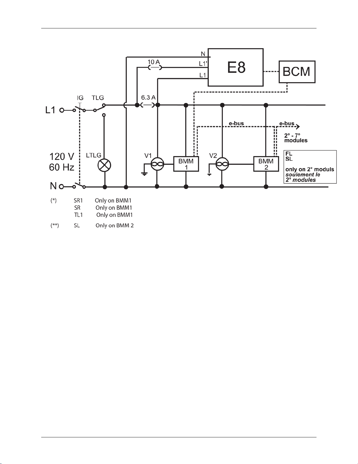
MODULEX EXT 321, 481, 641, 802, 962, 1123 BOILERS
Instal lati on, Operation & Maintenan ce Manual
3.27 General Ladder Diagram
Figure 3-31: General Ladder Diagram
3.28 E8 Controller and BCM Terminal Assignments
On the rear panel of th e E8 controller, th ere ar e two ter minal bloc ks, one of which is for the
mains (120 V) connections, and th e oth er f or the low voltage connections.
The mai n c ont rol s, nec ess ary for t he C/H system m anagemen t an d f or t he boi ler control, as w ell
some components which are part of the boiler housing, must be connected to the terminal
blocks. S ee F i g u re 3 -32 f or a wiring diagram showing the E8 controller terminal wiring, and see
Figure 3-33 for a wirin g diagram of sens or and BCM ter minal wiring.
Page 60 of 148 AERCO Int ernational, Inc. • 100 O ritani Dr. • Blauvelt, NY 1091 3 OMM-0087_0E
12/01/14 Phone: 800-526-0288 GF-143
Page 61

MODULEX EXT 321, 481, 641, 802, 962, 1123 BOILERS
Instal lati on, Operation & Maintenan ce Manual
Figure 3-32: E8 Controller Terminal Assignments
OMM-0087_0E AERCO International, Inc. • 100 Or itani Dr. • Blau velt, NY 10913 Page 61 of 148
GF-143 Phone: 800-526-0288 12/01/14
Page 62

MODULEX EXT 321, 481, 641, 802, 962, 1123 BOILERS
Instal lati on, Operation & Maintenan ce Manual
Figure 3-33: Sensor and BCM Terminal Assignments
Page 62 of 148 AERCO Int ernational, Inc. • 100 O ritani Dr. • Blauvelt, NY 1091 3 OMM-0087_0E
12/01/14 Phone: 800-526-0288 GF-143
Page 63

MODULEX EXT 321, 481, 641, 802, 962, 1123 BOILERS
Instal lati on, Operation & Maintenan ce Manual
3.29 Installation Examples
(Funct ional Wiri ng a nd Conn ections Description)
OMM-0087_0E AERCO International, Inc. • 100 Or itani Dr. • Blau velt, NY 10913 Page 63 of 148
GF-143 Phone: 800-526-0288 12/01/14
Page 64

MODULEX EXT 321, 481, 641, 802, 962, 1123 BOILERS
Instal lati on, Operation & Maintenan ce Manual
Page 64 of 148 AERCO Int ernational, Inc. • 100 O ritani Dr. • Blauvelt, NY 1091 3 OMM-0087_0E
12/01/14 Phone: 800-526-0288 GF-143
Page 65

MODULEX EXT 321, 481, 641, 802, 962, 1123 BOILERS
•
•
•
•
Instal lati on, Operation & Maintenan ce Manual
3.30 Starting Up: Filling and Deaerating the Boiler
Carry out the following tasks in connection with maintenance, etc. to an already installed unit:
Shut down all programs
Close the gas sh utoff valve u pst ream from t he boi ler
Shut of f the power at the main p ower switch
Close the C/H service v alves (supply and r etur n)
Necessary Precautions for Safety 3.30.1
Ob serve the following rules of sa fety:
• All work on the unit must take place in a dry environment.
• AERCO units should never b e in operat ion wit hout t heir cov er panels, except in connection with
maintenance or adju stment s.
• Never allow electr i cal or electroni c com ponents to come into con tact with water.
Supply Voltage, Gas Pressure, and Water pressure 3.30.2
The unit must be able to function during maintenance p rocedures or when adjustmen ts are
performed. For th is reas on, the uni t’s suppl y voltage, gas pressure and water press ure must be
maintained and available during th ese activities.
WARNING!
Following maintenance or other activities, always check the integrity
of al l p art s t hr ough w hic h g as flow s with a bubble t est us ing soap
spray to ensure th ere are n o gas leaks.
3.31 Filling the System
Neces sar y Pr ecaut ions Whil e F illing th e System 3.31.1
Do not mix the C/H system’s water with anti-freeze or anti -c orrosion solutions using incorrect
concentrations! Doing so can cause d amage to the gaskets and might cause noise during
nor mal b oiler operation.
WARNING!
AERCO r ef uses all liability for inju ry to persons , an i mals or damage
to prope r ty de riving fro m not having respected the above mentioned
recommendations.
Before fil ling the heat in g sy st em, th e complete system, includin g all zones, m ust be thorou ghly
cleaned and f lushed to remove sedimen t.
Flush until clean water runs free of sediment. AERCO suggests using an approv ed system
cleaner to f lush th e system, b ut n ot the boi ler . Always use AERCO ap proved anti fr eezes . See
the list in sec tion 1. 9. 3, Water Quali ty Requirements .
Never us e reverse osmosis, deionized, distilled wa ter or mi neral treated water for filling the
heating system.
OMM-0087_0E AERCO International, Inc. • 100 Or itani Dr. • Blau velt, NY 10913 Page 65 of 148
GF-143 Phone: 800-526-0288 12/01/14
Page 66

MODULEX EXT 321, 481, 641, 802, 962, 1123 BOILERS
Instal lati on, Operation & Maintenan ce Manual
WARNING!
Do n ot us e petr ol eum-based cleaning or seal ing c ompounds in the
boi ler s ystem . Dam age of s eals and g askets in b oiler and s ystem
could occur, resulting in substantial property damage and/or
danger.
The c ent ral heating installation needs to be fil led with clean water. Use only clean w ater or
approved glycol for filling t he heating system.
Wh en th e wat er hard ness of the fil li ng water exc eeds 9 grains, the water must be treated until
below the maxi mum v alue of 9 grains.
The pH value of the installation water must be between 6.5 and 8.5. Check the pH value using
proper equ ipment or by h aving th e water analyzed by a w ater tr eatment comp any.
If pH differ s from abov e, con tact AERCO engineering for fu rther assistance.
WARNING!
Fai lur e to adh ere t o th e wat er qu ality requ irem ents wi ll res ult in a
voidance of warranty.
Filling Lo cat ion s and Prepar ation 3.31.2
• For filling the system , a filling tap must be ins er ted on the system return pi pe.
• Filling can als o be accomplished through th e dr ai nin g tap on the boiler r eturn m anifold.
• In both c ases, an approved hydr aulic disc onnect ion system must be fitted.
• Befor e connecting the boiler, carefully ri nse out the whole sys tem with running water.
Page 66 of 148 AERCO Int ernational, Inc. • 100 O ritani Dr. • Blauvelt, NY 1091 3 OMM-0087_0E
12/01/14 Phone: 800-526-0288 GF-143
Page 67

MODULEX EXT 321, 481, 641, 802, 962, 1123 BOILERS
Instal lati on, Operation & Maintenan ce Manual
FOR YOUR S AFE TY RE AD BE FO RE OPE RA TIN G
WARNING: If you do not follow these instructions, a fire or explosion may result
causing property damage, personal injury, or loss of life.
A. This appliance does not have a pilot light. It is equipped with an ignition device,
which automatically lights the burner. Do NOT try to light the burner by hand.
B. BEFORE OPERATING smell all around the appliance area for gas. Be sure to smell
next to the floor, as some gas is heavier than air and will settle on the floor.
C. Use only your hand to turn the gas ball-valve knob. Never use tools. If the knob will
not turn by hand, d o NOT try t o repair it, but rather call a qual ified ser vice techn ician.
Force or attempted repair may result in a fire or explosion.
D. Do n ot u se this appliance if any par t has been submer ged under water. Immediately
call a qualified service technician to inspect the appliance and to replace any part of
the control system and any gas control device that has been submerged under water.
WHAT TO DO IF YOU SMELL GAS:
• Do not t ry to ligh t any applian ce
• Do not t ouc h or operate any electric switch
• Do not use any phone in the building
• Im m edi atel y c all y our gas su pp li er fr om a nei gh bor s p h on e or
from outside with your cell phone and follow the gas supplier’s
instructions.
OPERATING INSTRUCTIONS
1. STOP! Read the safety information above on this warning.
2. Turn off all elect ric power to the appli ance.
3. Op en t he gas v alve.
4. Ch eck gas and water press ure.
5. Wait five (5) minutes to cl ear out any g as, then smell for gas, incl udi ng near the fl oor.
6. If you s mell gas, S TOP! Follow the ins tr uct ion s “WHAT T O DO I F YOU S MELL GAS” th at
ar e printed above in t hese war nings. If you do not smell gas , g o to the next step.
7. Turn on al l electric p ower t o th e appli ance.
8. Turn the start-up switch (next to the E8 c ont rol ler) to the ON posit ion. Replace t he c ontrol
acces s panel.
9. Set Ther mostat to the desired t emperat ure.
10. If the appliance wi ll not operate, foll ow instruct ions t o tu rn of f t he gas ( see below) , an d then
call you r s ervice technician or gas suppli er.
TO TURN OFF GAS TO APPLIANCE
1. Set the thermostat to its lowest setting.
2. Turn off all elect ric power to the appli ance if s ervice is to be performed .
3. Cl ose th e gas valve.
OMM-0087_0E AERCO International, Inc. • 100 Or itani Dr. • Blau velt, NY 10913 Page 67 of 148
GF-143 Phone: 800-526-0288 12/01/14
Page 68

MODULEX EXT 321, 481, 641, 802, 962, 1123 BOILERS
Instal lati on, Operation & Maintenan ce Manual
3.32 Testing The Ignition Safety Shut Off Device
Ignition Safety Shutoff Device Test
1. Power on by swi tc hi ng on th e ON-OFF switch.
2. Create a req uest in C/H Centr al Heat in g using the E8 controller.
3. Turn burners ON.
4. Disconnect the igniter cable (WHITE) of BURNER 1 (See Fig ure 7-2).
NOTE
En s ure t h e c abl e en d i s not gr ou nd ed t o th e en c l osu r e fr ame, or t o
any other g rounded part .
5. The display will show ERRO R CODE E05 (Loss of Flame). S ee Figu re 3-34.
Figure 3-34: “Loss of Flame” Error Code (E 05)
6. Press Reset B utton on E 8 Cont roller .
7. The boiler will retry the i gnition cycle and the display wi ll show ERROR CODE E04 (No
Flame Detected During Ignition). See Fi gure 3-35.
Figure 3-35: “No Flame Detected During Ignition” Error Code (E 04)
8. Reconnect t he ignition cable of BURNER 1.
9. Press Reset B utton
10. Check that the boiler sta rt s c orrectly.
WARNING!
Do not tou ch the inside of th e ig nition cable whil e it is discon nected
du ring st art-up of th e boil er.
Page 68 of 148 AERCO Int ernational, Inc. • 100 O ritani Dr. • Blauvelt, NY 1091 3 OMM-0087_0E
12/01/14 Phone: 800-526-0288 GF-143
Page 69

MODULEX EXT 321, 481, 641, 802, 962, 1123 BOILERS
Instal lati on, Operation & Maintenan ce Manual
3.33 Burner Calibration
WARNING!
All the instructions indicated below are for the exclusive use of
qualified AERCO service technicians or installers.
All t he boilers are supplied al r e ad y c al i brat ed an d t es t ed . H owev er , i f it i s necessary to change
th e c ali br at ion du e t o g as con ver si on or ad apt at i on t o t he m ai ns sup pl y sy st em , t he g as val ve
must be re-calibrated (using Service Mode function in the E8 cont roller).
Installing the Gas Analyzer Probe 3.33.1
Bef ore m aking adju stm ents, a g as an alyzer sen sor probe m ust first be installed into the flue
exhaust outlet as shown in Fi gure 3-36.
Installing the Gas Analyzer Probe into Flue Outlet
1. Remove the cap (#2) from the gas outlet (#1)
2. Instal l the probe adap ter (#3) into the gas outl et ( #1) wher e cap w as removed.
3. Inser t the analysis probe ( #4) int o hole o f the pr obe adaptor .
4. Af ter measuremen ts are t aken and adju s tment s made, r emove the p robe, probe adaptor,
then reinstall the cap (#2) onto the gas outlet (#1).
Figure 3-36: Gas Analyzer Probe Location in Flue Outlet
OMM-0087_0E AERCO International, Inc. • 100 Or itani Dr. • Blau velt, NY 10913 Page 69 of 148
GF-143 Phone: 800-526-0288 12/01/14
Page 70

MODULEX EXT 321, 481, 641, 802, 962, 1123 BOILERS
Maximum
Output Adjust
Minimum
Output Adjust
Instal lati on, Operation & Maintenan ce Manual
A
B
Figure 3-37: Loc ati on of Minimum and Maximum Adjustments (Top View)
Maximu m Output Calibration 3.33.2
After installing the gas analyzer probe (Figure 3-36), refer to Figure 3-37 to locate the gas
valves and the Maximum Gas Adjustment screw (A) on each valve. Follow the instructions
below to set the maximum gas ou tp ut level fo r each valve.
Adjusting the Maximum (A) Gas Output Setting
1. Remove the cap of the combustion gases sampling point (Figure 3-36) and connect a
suitable gas analyzer.
2. Op erat e t h e bur n er t o a m i nim um pow er fol l ow in g t he procedure described in S ection 3.34
(Figure 3-39) ‘’Sweeper’’ function (CASCADE MAN 100%).
3. Ch eck th at the CO
values are within the values indicated in Table 3-6.
2
4. If necessary, correct the value by turning the adjustment screw “A” in a CLOCKWISE
direction t o decrease the v alue or ANTICLOCKWISE to in creas e the v alue.
5. Repeat the adj ustmen t f or all g as v alves in th e boiler.
Page 70 of 148 AERCO Int ernational, Inc. • 100 O ritani Dr. • Blauvelt, NY 1091 3 OMM-0087_0E
12/01/14 Phone: 800-526-0288 GF-143
Page 71

MODULEX EXT 321, 481, 641, 802, 962, 1123 BOILERS
Instal lati on, Operation & Maintenan ce Manual
Minimum Output Calibration 3.33.3
After setting the maximum gas output for each valve (section 3.33.2), refer to Figure 3-37,
above, t o l ocate th e Mi n i m um G as A dj u s tmen t s c r ew (B ) on e ac h v al ve. F ol low t h e i n st r u c t i ons
below to set the mi ni mum g as outp ut level for eac h v alve.
Adjusting the Minimum (B) G as Output Setting
1. Operate the burner to a m inimum power following the proc edure described in section 3.34
(Figure 3-39) ‘’Sweeper’’ function (CASCADE MAN 10%).
2. Ch eck th at the CO
3. If necessary, correct the value by turning the adjustment screw “B” in a CLOCKWISE
direction t o in creas e th e value or ANTI CLOCKWISE t o dec rease it the value.
4. Repeat the adj ustmen t f or all g as v alves in th e boiler.
If the CO2 perc ent age i s t oo l ow , c hec k i f th e air and exhaust flue
are obstructed. If they are not obstructed, check if the burner and/or
the exchanger (aluminum sections) are properly cleaned. After
con f i rm at i on, ch ec k th e maximum g as s et t i ng s ag ai n , as d es c r i bed
in section 3.33.2, above.
values are within the values indicated in Table 3-6.
2
NOTE
Final Ch e ck and Ignition Failure Adju stm ent Proced ure 3.33.4
After completing t he Minim um and Maximum output adjustments, c h ec k th e C O2 m inimum and
maximum valu es at the f lue outlet and, if n eces sary, make any required adjustments.
If the boil er f ail s t o igni te, perf orm the f ollow in g proc edure:
Ignition Failure Adjustment Procedure
Figure 3-38: Maximum Output Adjustment Screw
1. Ti ght en t he m axim um adj ustm ent sc rew “A” in a c loc kwi se dir ect ion u nti l it is fully abutted
int o th e gas val ve body, t han slack en b ac k ou t for ni ne (9) turns.
2. Verify boiler ignition.
3. If the boiler goes into l ock out, slacken t he screw “A” again for one turn, than ret ry ignition.
4. If the boil er goes into lockou t again, repeat step 3 and retry ignition.
5. Once ignition succeeds, carry out the minimum and maximum gas output burner
adjustments as previously describ ed in sections 3.33. 2 and 3.33.3, above.
OMM-0087_0E AERCO International, Inc. • 100 Or itani Dr. • Blau velt, NY 10913 Page 71 of 148
GF-143 Phone: 800-526-0288 12/01/14
Page 72

MODULEX EXT 321, 481, 641, 802, 962, 1123 BOILERS
EXT 321
Ǿ Mixer
Injectors
Consumption
EXT 481
Ǿ Mixer
Injectors
Consumption
EXT 641
Ǿ Mixer
Injectors
Consumption
Instal lati on, Operation & Maintenan ce Manual
Table 3-6: Modulex EXT Pressure, CO2 and O2 Level Calibration Tables
Gas
Type
Natural
Propane
Natural
Propane
Gas
Type
Natural
Supply
Pressure
Wc (kPa)
7 (1.74) 8.5 10 3.1 5.8 31 91 0.27 (7) 45 (1.29) 316 ( 8.95) 50
11 (2.74) 10 11 1.3 3.1 30 84 0.27 (7) 18 (0.50) 122 (3.46) 50
7 (1.74) 8.5 10 3.1 5.8 35 100 0.27 (7) 45 (1.29) 316 ( 8.95) 50
11 (2.74) 10.8 10.8 1.3 3.1 30 73 0.27 (7) 18 (0.50) 109 (3.11) 50
CO2 Level O2 Level Fan Speed
(%)
Min.
(%)
Max.
(%)
Min.
(%)
Max.
Min.
Max.
(FL)
(FH)
NOMINAL ALTITUDE
HIGH ALTITUDE
Ǿ in.
(mm)
Min. Gas
Consumption
ft3/hr (m3/hr)
Max. Gas
ft3/hr (m3/hr)
Start
Output
% IG
Supply
Pressure
Wc (kPa)
7 (1.74) 7.5 10 3.1 5.8 31 91 0.27 (7) 45 (1.29) 474 (13.43) 50
CO2 Level O2 Level Fan Speed
(%)
Min.
(%)
Max.
(%)
Min.
(%)
Max.
Min.
Max.
(FL)
(FH)
NOMINAL ALTITUDE
Ǿ in.
(mm)
Min. Gas
Consumption
ft3/hr (m3/hr)
Max. Gas
ft3/hr (m3/hr)
Start
Output
% IG
Propane
Natural
Propane
Gas
Type
Natural
Propane
Natural
Propane
11 (2.74) 10 11 1.3 3.1 30 84 0.27 (7) 18 (0.50) 183 (5.19) 50
HIGH ALTITUDE
7 (1.74) 8.5 10 3.1 5.8 35 100 0.27 (7) 45 (1.29) 474 (13.43) 50
11 (2.74) 10.8 10.8 1.3 3.1 30 73 0.27 (7) 18 (0.50) 164 (4.67) 50
Supply
Pressure
Wc (kPa)
7 (1.74) 8.5 10 3.1 5.8 31 91 0.27 (7) 45 (1.29) 631 (17.87) 50
11 (2.74) 10 11 1.3 3.1 30 84 0.27 (7) 18 (0.50) 243 (6.88) 50
7 (1.74) 8.5 10 3.1 5.8 35 100 0.27 (7) 45 (1.29) 631 (17.87) 50
11 (2.74) 10.8 10.8 1.3 3.1 30 73 0.27 (7) 18 (0.50) 219 (6.23) 50
CO2 Level O2 Level Fan Speed
(%)
Min.
(%)
Max.
(%)
Min.
(%)
Max.
Min.
Max.
(FL)
(FH)
NOMINAL ALTITUDE
HIGH ALTITUDE
Ǿ in.
(mm)
Min. Gas
Consumption
ft3/hr (m3/hr)
Max. Gas
ft3/hr (m3/hr)
Start
Output
% IG
NOTE
Check the O
For high altitude installations, consult document number C302.6 (MLX EXT Alt Derate).
levels often, es pecially at low f l ow r at es .
2
Page 72 of 148 AERCO Int ernational, Inc. • 100 O ritani Dr. • Blauvelt, NY 1091 3 OMM-0087_0E
12/01/14 Phone: 800-526-0288 GF-143
Page 73

MODULEX EXT 321, 481, 641, 802, 962, 1123 BOILERS
EXT 802
Ǿ Mixer
Injectors
Consumption
EXT 962
Ǿ Mixer
Injectors
Consumption
EXT 1123
Ǿ Mixer
Injectors
Consumption
Instal lati on, Operation & Maintenan ce Manual
Table 3-6: Modulex EXT Pressure, CO2 and O2 Level Calibration Tables
Gas
Type
Natural
Propane
Natural
Propane
Gas
Type
Natural
Supply
Pressure
Wc (kPa)
7 (1.74) 8.5 10 3.1 5.8 31 91 0.27 (7) 45 (1.29) 790 (22.39) 50
11 (2.74) 10 11 1.3 3.1 30 84 0.27 (7) 18 (0.50) 306 (8.65) 50
7 (1.74) 8.5 10 3.1 5.8 35 100 0.27 (7) 45 (1.29) 790 (22.39) 50
11 (2.74) 10.8 10.8 1.3 3.1 30 73 0.27 (7) 18 (0.50) 274 (7.79) 50
CO2 Level O2 Level Fan Speed
(%)
Min.
(%)
Max.
(%)
Min.
(%)
Max.
Min.
Max.
(FL)
(FH)
NOMINAL ALTITUDE
HIGH ALTITUDE
Ǿ in.
(mm)
Min. Gas
Consumption
ft3/hr (m3/hr)
Max. Gas
ft3/hr (m3/hr)
Start
Output
% IG
Supply
Pressure
Wc (kPa)
7 (1.74) 8.5 10 3.1 5.8 31 91 0.27 (7) 45 (1.29) 948 (26.87) 50
CO2 Level O2 Level Fan Speed
(%)
Min.
(%)
Max.
(%)
Min.
(%)
Max.
Min.
Max.
(FL)
(FH)
NOMINAL ALTITUDE
Ǿ in.
(mm)
Min. Gas
Consumption
ft3/hr (m3/hr)
Max. Gas
ft3/hr (m3/hr)
Start
Output
% IG
Propane
Natural
Propane
Gas
Type
Natural
Propane
Natural
Propane
11 (2.74) 10 11 1.3 3.1 30 84 0.27 (7) 18 (0.50) 367 (10.39) 50
HIGH ALTITUDE
7 (1.74) 8.5 10 3.1 5.8 35 100 0.27 (7) 45 (1.29) 948 (26.87) 50
11 (2.74) 10.8 10.8 1.3 3.1 30 73 0.27 (7) 18 (0.50) 329 (9.35) 50
Supply
Pressure
Wc (kPa)
7 (1.74) 8.5 10 3.1 5.8 31 91 0.27 (7) 45 (1.29) 1,106 (31.34) 50
11 (2.74) 10 11 1.3 3.1 30 84 0.27 (7) 18 (0.50) 428 (12.12) 50
7 (1.74) 8.5 10 3.1 5.8 35 100 0.27 (7) 45 (1.29) 1,106 (31.34) 50
11 (2.74) 10.8 10.8 1.3 3.1 30 73 0.27 (7) 18 (0.50) 384 (10.91) 50
CO2 Level O2 Level Fan Speed
(%)
Min.
(%)
Max.
(%)
Min.
(%)
Max.
Min.
Max.
(FL)
(FH)
NOMINAL ALTITUDE
HIGH ALTITUDE
Ǿ in.
(mm)
Min. Gas
Consumption
ft3/hr (m3/hr)
Max. Gas
ft3/hr (m3/hr)
Start
Output
% IG
NOTE
Check the O
For high altitude installations, consult document number C302.6 (MLX EXT Alt Derate).
levels often, es pecially at low f l ow r at es .
2
OMM-0087_0E AERCO International, Inc. • 100 Or itani Dr. • Blau velt, NY 10913 Page 73 of 148
GF-143 Phone: 800-526-0288 12/01/14
Page 74

MODULEX EXT 321, 481, 641, 802, 962, 1123 BOILERS
Instal lati on, Operation & Maintenan ce Manual
3.34 Sweeper Mode (Manual Control)
Figure 3-39: Sweeper Mode (Manual Control)
NOTE
The function is active for 15 minutes, after which, if there is no
input , i t defaul ts to t he previous parameters.
Page 74 of 148 AERCO Int ernational, Inc. • 100 O ritani Dr. • Blauvelt, NY 1091 3 OMM-0087_0E
12/01/14 Phone: 800-526-0288 GF-143
Page 75

MODULEX EXT 321, 481, 641, 802, 962, 1123 BOILERS
This conversion to high altitude
operation shall be made by a
qualified service agency in
having jurisdiction. The qualified
specified in the manufacturer’s
Instal lati on, Operation & Maintenan ce Manual
3.35 High Altitude Adjustment
It is necessary to adjust the fan speed at al t i t u des at or above 5 , 0 00 f eet . M odif y th e p arameter
FAN MAX from the E8 C ont rol P anel . Not e th at i t is m od if iab l e onl y w i th an ac c ess c od e. See
Table 3-7 on the next page f or a li st of th e FA (Factory) par ameters.
WARNING!
accordance with the manufacturer’s
instructions and all applicable codes
and requirements of the authority
service agen cy is res ponsib le for t he
proper installat ion of this conversion.
The installation is not proper and
complete until the operation of the
converted appliance is checked as
instructions supplied with the unit.
2
NOTE
Figure 3-40: Adjusting Fan Speed to Se t Input Range for High Altitude
(FAN MAX) in Tabl e 3-7, and
Modulex EXT Pressure and CO
Level Cali bration in Table 3-6.
See th e value of parameter FH
OMM-0087_0E AERCO International, Inc. • 100 Or itani Dr. • Blau velt, NY 10913 Page 75 of 148
GF-143 Phone: 800-526-0288 12/01/14
Page 76

MODULEX EXT 321, 481, 641, 802, 962, 1123 BOILERS
MODULEX EXT
For Low Altitude
For High Altitude
FAN MOD IGN
80
No Change
FAN MOD STBY
26
No Change
FAN MAX (FH)
91
78
FAN MIN (FL)
31
No Change
MAX DIFF PRO
30
No Change
MIN FLOW PRO
00
No Change
MIN F LOW RAT
200
No Change
BOIL HY S
5
No Change
BO IL SLP LIM
10
No Change
BO IL P VAL
25
No Change
BOIL I VAL
12
No Change
BOIL D VAL
00
No Change
PUMP OVERRUN
05
No Change
PUMP MI N MOD
----
----
CAP FLOW RATE
----
----
FAN P VAL
04
No Change
FAN I VAL
08
No Change
FAN SLP
FAN SLP POS
----
----
FAN SLP NEG
----
----
FAN START PW
----
----
FAN ADAPT
----
----
RESTARTS
----
----
SW NO
Software N°
Software N°
SW RWV
Software Revision
Software Revision
Instal lati on, Operation & Maintenan ce Manual
Table 3-7: MODULEX EXT FA (Factory) Parameters Set in PARAM HS xx Menu
Parameters
3.36 High Altitude Conversion Label
After c alib rati on of the unit f r om Norm al A lti tude ( 0 - 2,000 feet) t o H i gh Altit ud e (2,00 0 –
4,500 feet) operat i on, the lab el bel ow mus t be fil l ed out wit h the ap pr opri ate inf orm ation
and appl i ed to th e un it i n c lose proximit y to th e rati ng l ab el . If t h e unit i s c alibrated again
for nor m al alt itude oper ati on, the l ab el sh oul d be rem ov ed .
Figure 3-41: High Altitude Co nv ersi on La bel
Page 76 of 148 AERCO Int ernational, Inc. • 100 O ritani Dr. • Blauvelt, NY 1091 3 OMM-0087_0E
12/01/14 Phone: 800-526-0288 GF-143
Page 77
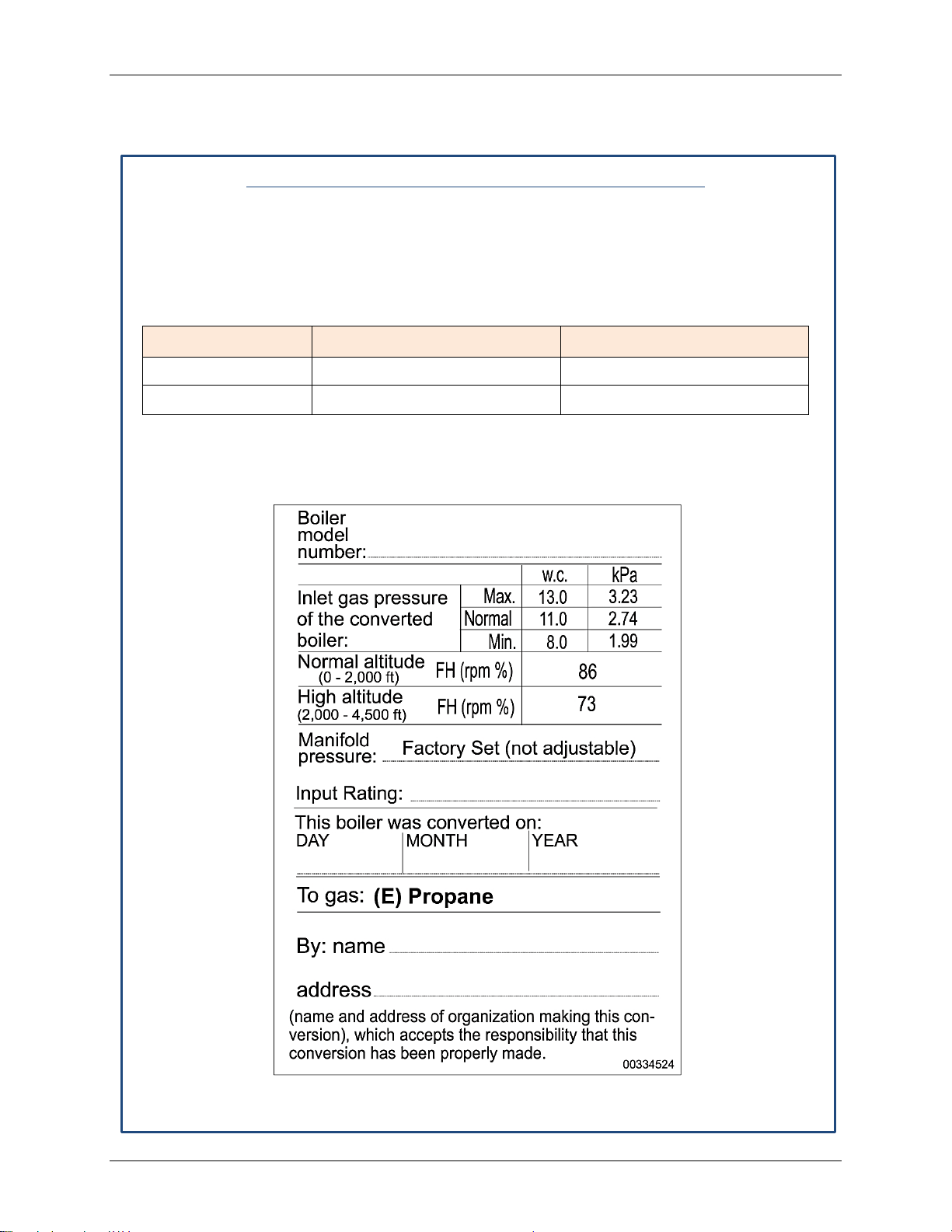
MODULEX EXT 321, 481, 641, 802, 962, 1123 BOILERS
Natural Gas
Instal lati on, Operation & Maintenan ce Manual
3.37 Conversion From Natural Gas To Propane Gas
To con ver t the unit to u se pr opane gas , inst ead of n atu ral gas, do t he f ollowing:
Converting From Natural Gas to Propane Gas
1. Set nom in al he at by adju sti ng t he f an sp eed p aram et er FH (FA N MAX ) fr om t he E 8
controller as shown in Table 3-7, and Modulex EXT Pressure and CO
2
Calibration in Table 3-6, above. T his paramet er requires a password to change.
2. Adjust CO
(% ) m i nimum and m aximum l evel s ac c or di n g t o t h e t ype o f ga s a s show n
2
in t able below. See sec tion 3. 33, Burner Cal ibrat ion for more i nf ormation.
Gas Type CO2 Level (%) Minimu m CO2 Level (%) Maximum
8.5 10
Propane Gas 10 11
Af ter gas c onver sion to propane and cali brat ion, the gas instal ler should complete and
3.
app ly th is lab el, or equ ivalen t, as close to t he rat in g label as pos s ib le:
Level
Figure 3-42: MODULEX EXT Label
OMM-0087_0E AERCO International, Inc. • 100 Or itani Dr. • Blau velt, NY 10913 Page 77 of 148
GF-143 Phone: 800-526-0288 12/01/14
Page 78

MODULEX EXT 321, 481, 641, 802, 962, 1123 BOILERS
B
C
Fuses: 1 = 6.3 A 2 = 10 A
D
Warni ng l amp of th e Th ermostati c Lockout f rom G TL (General Limit Thermostat).
E
E8 Cont roller Module
F
Hydrometer ( Optional)
I*
Instal lati on, Operation & Maintenan ce Manual
3.38 Controls And Emergency Functions
Figure 3-43: MODULEX EXT Panel Controls and Indicators
ITEM COMPONANT/FUNCTION
GLT ( Gene ral Lim it Ther most at) : w hen en abl ed, it cut s th e pow er sup ply to t h e
A
boi l er and l ig ht s t h e w arni ng l am p ( It em D) . T o re set , rem ov e t h e c ap an d pu sh
the reset but ton.
Main P ower Switch
Change-over Series/ Parallel:
0 = Emergenc y is ac tive or th e cont rol is man aged by PLC or BMS.
G*
I = Series connecti on (th e cas cade is managed by th e BC M )
II = Parallel connection (condition of supply).
H*
In p osi t i on “ I ” t he p l an t w i l l operate wh en req ue sted at “ CO N S T A NT SE T PO I N T” :
70°C –
Max heat output 50%.
Enables burner reset i n c ase of lock-out.
YELLOW LED = Blinking = Communication bet ween BMM and BCM is OK.
J*
GREEN LED = ON = Active Pump
RED LED = ON = F ail ure Code D etected
*See secti on 4.2 , below, for more information r egarding the BCM (B oil er Communication
Module).
NOTE
The emergency function enables the boiler’s burners to fire only at 50% and at
50°C in system return. All the system’s heating loads, including the header pump,
must be controlled manu ally.
Page 78 of 148 AERCO Int ernational, Inc. • 100 O ritani Dr. • Blauvelt, NY 1091 3 OMM-0087_0E
12/01/14 Phone: 800-526-0288 GF-143
Page 79

MODULEX EXT 321, 481, 641, 802, 962, 1123 BOILERS
•
•
•
•
•
•
•
•
•
•
•
•
•
•
•
Instal lati on, Operation & Maintenan ce Manual
3.39 Initial Boiler Ignition
Preliminary Checks 3.39.1
WARNING!
To ensure the continued safe operation of the boiler it is highly
recommend ed th at i t is c hec ked at r egu l ar i nt erv al s and se rv ic ed
when necessary, and that only original spare parts are used.
Reg ular attention w ill prolong the life of the boil er.
Before ign iti ng t he boil er check th at:
The boi l er i ns tal l at ion has be en c ar ri ed out in acc ordanc e wit h the specific standards as
instructed in this manual.
The c ombustion air inlet and t he discharge of combust ion exhaust occ ur in the correct
manner in accor dance to the s pecific st andards in for ce.
The gas supply system is correctly configured for the boiler’s output.
The b oiler ’s electrical supply is 120 V - 60 Hz.
The system h as be en f il l ed w it h wat er ( pr es sur e r egi st er ed on t he g aug e 0.8/1 bar with
pump not running).
All of the system’s on/off valves are in the appropriate position (open or closed as
required)
The m ains gas supply corresponds to the one which the boiler has been calibrated for.
Otherwise convert the boiler to use the available gas (refer to section: “GAS
CONVERSION”). This operation must be carried out by a qualified technician in
compliance with the regulations in force.
The g as supply valv e is open.
There are no gas leak s.
There are no w ater leak s.
The e xternal mains elec tr ical sup pl y sw itch is on .
The boiler system’s safety valve is not blocked and is connected to the waste water
system.
The condensate drain line (section 3.14) has been filled with water and that it is
connected to th e was te water s ys tem.
WARNING!
Before firing up the appliance, be sure to fill up the condensate
drain line ( see sec ti on 3. 14) through the f illi ng hol e and ch eck th e
correct drainage of the condensate.
Using the boi ler with the condensate drain pipe empt y c oul d c ause
a dangerous condition due to poisonous emissions from the flue
exhaust gasses.
All the necessary ventilation conditions and m in i mum clearance d istances are in plac e for
subsequent servicing in case the boiler is sited in a cupboard compartment.
There are no w ater leak s.
OMM-0087_0E AERCO International, Inc. • 100 Or itani Dr. • Blau velt, NY 10913 Page 79 of 148
GF-143 Phone: 800-526-0288 12/01/14
Page 80

MODULEX EXT 321, 481, 641, 802, 962, 1123 BOILERS
Instal lati on, Operation & Maintenan ce Manual
Page 80 of 148 AERCO Int ernational, Inc. • 100 O ritani Dr. • Blauvelt, NY 1091 3 OMM-0087_0E
12/01/14 Phone: 800-526-0288 GF-143
Page 81

MODULEX EXT 321, 481, 641, 802, 962, 1123 BOILERS
•
•
•
•
•
•
•
Instal lati on, Operation & Maintenan ce Manual
CHAPTER 4: E8 CONTROLLER AND BCM MODULES
MODULEX b oil ers con tai n ad v anc ed and r el iab l e el ec tr oni c c ont r ols, t he E 8 C ont rol ler and t he
BCM (Boiler Communications Module), which provide comprehensive programming and
monit ori ng of th e MODULEX boiler and its functions. Features and functions of the E8 Controller
and BCM are described in this chapter.
CAUTION!
This chapter instructs how to operate and navigate the E8
Controller menus, sub-menus, and parameters, as well as
describing the functions of the BCM (Boiler Control Module).
However, befor e th e boi ler m ay b e used, th e E8 c ontr oll er MUST
be first intitial ized by entering language, year, month, day, and hour
in t he In stallation Menu, described in section 5.1.
4.1 E8 Controller
A standard component included in MODULEX units, the E8 Controller is responsible for the
staging and modulation of individual th ermal heating m odules in a MODULEX boi ler and also
monit ors s uppl y and ret urn wat er t emperatu res and d omestic hot wat er zones .
The E8 Contr oller i s housed i n a compact enclosure measuring 5.7” (145 mm) x 3.9” (100 mm).
Th e C on t r ol l er i s m ou n t ed on t he f r on t of t he MODULEX Boi l er an d c on tai n s al l of the c on t rol s ,
indicators and displ ays necessary to adjust, op erate and troubleshoot the MODULEX Boiler.
The m ain com ponent s of the closed E8 Controller include the display, door, and data wheel
(see Figure 4-1).
E8 Controller Features and Fun cti ons 4.1.1
The E8 features the following functions for MODULEX boilers:
Shares the heating load among as many of the boiler's thermal heating modules as
possible, maximi z in g th e overall operati ng effici ency of th e boi ler.
Provides access to all t es ting/ programming par ameters of eac h individ ual heat in g
module: op eration t es t, operation t i me, boiler freeze protection and pump's anti seize
program.
Drives l e ad-lag burner operation bas ed on operat in g hours . The boiler mod ule with t he
least burner operating hours is the first to start and the burner with the most operating
hou rs is the first t o st op.
Supports DHW (D omestic Hot Wat er) prod uct ion using a dedicated sens or t o control a
ded icated pump or 3-way diverti ng valve for st orage tank temperature con trol.
Supports a manu al operat ion serv ice mode to con tr ol i ndivid ual mod ul es dur in g
troubleshooting or combustion calibration procedures.
Drives di agnosti cs such as relay and s enor t est ing.
Supports Modbus integration with AERCO BMS II and AERCO Control System (ACS) or
Build in g Autom ation Syst ems. AER CO also offers a Commu nicat ion Gatew ay t o sup port
BAC net , Lonworks and N2 s ystem integration.
OMM-0087_0E AERCO International, Inc. • 100 Or itani Dr. • Blau velt, NY 10913 Page 81 of 148
GF-143 Phone: 800-526-0288 12/01/14
Page 82

MODULEX EXT 321, 481, 641, 802, 962, 1123 BOILERS
Item
Function
A
B
H
Rotary Knob
LCD Display
Hinged Cover
(in closed position)
A
B C D E F
G H I
Instal lati on, Operation & Maintenan ce Manual
Window
Figure 4-1: MODULEX E8 Controller Front Panel (Cover Closed)
E8 Display Functions 4.1.2
Th e E 8 C on t r oller op er ates i n N O R M A L M ode wh en t h e c on t rol l e r d o or i s c l osed , wh i c h al l ow s
for monitoring the boiler status through the display window and setting the HEATING Mode.
W hen the door is op ened, the unit enters MENU Mod e, an d in t his m ode the boil er m ay be
initialized, configured, and adjust ed. The controls and display for the E8 cont roller are de sc ri bed
in the following sub-sections.
Figure 4-2: E8 (NORMAL Mode) Display Features
Table 4-1: E8 (NORMAL Mode) Display Features and Functions
Current time (2 4 hour format)
DCF rec eption OK (only if receiver is connected via eBUS)
Disp lay of the ac tive heat ing p rogram for t he first heatin g circu it (here: 6:00 to 08 :00 a.m. and
C
4:00 to 10:00 p.m.)
Bu s icon (if th is icon does not app ear, check data line t o conn ected CA N controllers => check
D
eBUS via DISPLAY level)
Status display: Shows symbols for Internal Burner 1 Relay ON; Heating Mode; Hot Water
E
Preparation.
Heatin g Mod e d ispl ay symb ol. The d is p lay sym b ols ap p ly to al l in t ern al h eati ng c irc u it s for whic h
F
a separat e he atin g m ode has b een s elected . Not e that each s ymb ol occup ies a di fferent spac e
across the display bottom. See Figure 4-3.
G
Display of current temperature of HS 1 or header temp er ature wh en cascading.
Display of numb er of active heat generators (only ap plies when cascading).
I
Selectable display and Error C odes (refer to " DISPLAY SEL" parameter in the USER menu).
Page 82 of 148 AERCO Int ernational, Inc. • 100 O ritani Dr. • Blauvelt, NY 1091 3 OMM-0087_0E
12/01/14 Phone: 800-526-0288 GF-143
Page 83

MODULEX EXT 321, 481, 641, 802, 962, 1123 BOILERS
the bottom of the display. It takes effect when the
e 1; HW
rature; HW
Heating Mode
Instal lati on, Operation & Maintenan ce Manual
E8 HEATING Mode Selection 4.1.3
Heating modes may be selected using the Rotary Knob on the controller when the hinged door
is in the closed position (NORMAL Mode). As the Rotary Knob is turned, each appropriate
heating mode symbol is displayed, in turn, along the lower edge of the display.
Mode c hang es tak e eff ect when t he set ting i s not ch anged f or 5 s econd s. T he sym bols and
description for the available heating modes are shown in Figure 4-3.
Figure 4-3: E8 HEATING Mode Display Features (NORMAL Mode)
Symbols: Only the
one currently
selected mode wil l
be displayed.
Table 4-2: E8 HEATING Mode Features and Functions (NORMAL Mode)
SYMBOL MODE NAME DESCRIPTION
Turn the Rotary Knob to select the heating mode
Heating Mode
Selection
Standby / OFF
Automatic Mode 1
Automatic Mode 2
Summer Mode Heating OFF, HW according to HW program.
Day Mode
Night Mode
required. The heating m ode is indic ated by a sym bol at
setting is not changed for 5 seconds.
Heat OF F and hot w at er (HW ) p repar ation OFF , only
frost p rotection mode.
Heat according to timer program 1; HW according to
HW program.
Heat according to timer program 2; HW according to
HW program.
24 Hour heating with comfort temperatur
according t o HW prog ram.
24 Hour heating with reduced tempe
according t o progr am.
Service Mode
Automatic reset after 15 minutes. Boiler regulated at
max boiler temp erature.
OMM-0087_0E AERCO International, Inc. • 100 Or itani Dr. • Blau velt, NY 10913 Page 83 of 148
GF-143 Phone: 800-526-0288 12/01/14
Page 84

MODULEX EXT 321, 481, 641, 802, 962, 1123 BOILERS
FEATURE
Select ed M enu/Sub-menus , par ameter names/ values, and selected
busses are indicated in the LCD display when in MENU Mode.
Mounting Key
Access Holes
Inser t narrow scr ewdriver deep i nt o holes and lift u p cont roller to
Wh en lit, this LED indicat es that th e value s hown in the disp lay can
be changed using the Rot ary K nob (A).
Optical
Adaptor
Used t o select a sub-menu level, select a parameter value to
change, or sav e a new p arameter v alue.
A 2-posi tion (10/ 2 o’clock) sc rewdr iver adjust able switch . Normally,
EXPERT/INSTAL LATION me nu ) .
Used t o navigate through menus and parameters or adjust
parameters.
INSTALLATI
ON
A B C
D
E
F G B
Instal lati on, Operation & Maintenan ce Manual
E8 MENU Mode Operation (Door Open) 4.1.4
Opening the E8 controller hinged door reveals the E8 controls (Figure 4-4) and initiates the
ME NU Mode, whi ch enables access to an extensive s et of software men us.
Figure 4-4: E8 MENU Mode D is p l ay Features
Table 4-3: E8 MENU Mode Feat ur e s and Functions
ITEM
A
B
C
D
E
F
LCD display
Change LED
Program Key
Manual/
Automatic
Switch
remove.
For PC connection
thi s switch i s set to the Automati c (2 o’cl ock ) pos iti on t o all ow
pr ogram control of th e boi ler. When set to the M anual (10 o’clock)
position, a flashing “EMERG – MODE” mess age is displayed.
Heating Circuit 1 (HC1) pump and the first burner stage are switched
on. P umps for H eat in g Circu i t 2 ( HC2) an d Domest ic Hot Water
(DHW) w i ll also be s wit ched on if sensor s are ins tall ed and enab led.
The pump(s) will turn off when the flow temperature reaches the
val ue set for MA X T-FLOW (in EXPERT/HEAT CIRCUIT 1 menu).
The fi rst b urner stage will cut off w hen th e boi le r t emperatu re
re ach es th e value set fo r MAX T -MODUL (in
FUNCTION
G
Page 84 of 148 AERCO Int ernational, Inc. • 100 O ritani Dr. • Blauvelt, NY 1091 3 OMM-0087_0E
12/01/14 Phone: 800-526-0288 GF-143
Rotary K nob
Page 85

MODULEX EXT 321, 481, 641, 802, 962, 1123 BOILERS
INSTALLATI
Sub-MENU Name
Points left to
Points down to
MENU
Points down to
Points right to
Buss(es)
Sub-MENU
Instal lati on, Operation & Maintenan ce Manual
E8 MENU Nav i g ati o n an d Par am eter S ett in gs 4.1.5
The selected Menu and Sub-menu are indicated by two black arrows at display bottom
pointing to th e Menu and Sub-m enu names sil k-screened bel ow t he di splay (Figu re 4-5).
Followin g initial st artup and one-t ime entry of t he requir ed I NSTALLATIO N menu items (see
section 5.1), to access, view and/o r ch ange me nu items follow these ins tructions:
Selected
Selected Buss(es)
Selected
MENU Name
Names
Selected
Sub-MENU Name
Names
Figure 4-5: MODULEX E8 Controller Front Panel
E8 Controller Menu Navigation Procedure
1. When the ON/OFF switch on the front of the boiler is turned ON and the swing-do wn hinged
panel is op ened, the c ont rol ler will enter M EN U Mode and I NS TALLAT ION wi l l be di splayed
(Figure 4-5) in the LCD. This is the initial INSTALLATION m enu and i t is assumed that all
entries have already been made. See sub-section 4.8 of the E8 Controller User Manu al
(GF-115-C) for IN STALLATI ON men u initial entry infor mation.
2. T u rn t h e R ot ar y K nob c l ock w i se u n t i l th e d i sp l ay ad v an c es to t h e D I S P LAY m en u . Th e di al
on t he c lock fac e wi ll r otat e on e rev olut ion coun ter cl ockw ise an d t hen g o of f. T he di spla y
will then show INSTALLATION, which is the first sub-menu in the DISPLAY menu group
(Figure 4-5). T h e t w o s m al l b l ac k ar r ow s at the b ottom of the display w ill point down to the
menu and submenu names, in t hi s case DI SPLA Y and INSTALLA TION, respec tively.
3. To view funct ions included in the INST ALLATIO N sub-men u , pr es s t he P rog r am Key (I tem
E, Figure 4-4). If desired, turn the Rotary Knob to scroll through the functions in the
INSTALLATION sub-menu. A s p rev i ou s l y men t i oned , these display functions are r ead-only
and cannot be changed. Once you r each the end of the sub-menu, RETURN will appear in
the display.
4. To exit t his su b-menu and advance to the next sub-menu in the DISPLAY menu, press the
Program Key while RETURN i s displayed. INSTALLATIO N will again be di splayed. Turn the
Rotary Knob c lockwise u nt il th e next sub-menu is displayed.
5. Repeat steps 2, 3 and 4 to view the remaining main menus and their associated submenus. The remaining m ain menus are: USER, TIME PROGRAM, EXPERT, EXPERT HS
(Not Appl i cab le to MODULEX), and GENERAL.
OMM-0087_0E AERCO International, Inc. • 100 Or itani Dr. • Blau velt, NY 10913 Page 85 of 148
GF-143 Phone: 800-526-0288 12/01/14
Page 86

MODULEX EXT 321, 481, 641, 802, 962, 1123 BOILERS
Use Rota ry Knob t o navigate to the desired Menu/Sub-
HOT-WATER
Display Detail
Displayed
Sub-menu
Example: User M enu & Hot Water Sub-menu
displayed
sub-menu
parameters
push
HOT-WATER
T-DHW
T-DHW
Cycle thru
T-DHW
displayed
values
push
140.0
141.0
cycle thru
142.0
displayed
value
Displayed
push
142.0
Instal lati on, Operation & Maintenan ce Manual
E8 Paramet er Nav ig atio n, S el ection, and Sett ing 4.1.6
When in the USER, TIME PROGRAM, EXPERT, or GENERAL Main Menu, virtually all submenu items can be changed, if desired. Perform the following steps to access, view, and/or
change men u item parameters :
Table 4-4: E8 P ar a m eter Na vig atio n, Sel ec tion, and Setting
Description Examples
menu. Menu and sub-menu are indicated by two small
blac k arrows at the bott om of the LCD display pointing
down to menu/sub-menu names below the displ ay (see
Figure 4-5).
Press Program Key to acc ess p arameter s in the s elected
(displayed) sub-menu.
accessed
Turn Rot ary Knob t o sequence through the availab le
parameters.
To ch ange a paramete r value, press the Program Key
when the d esired parameter is di splayed . The Chan ge
LED w ill light up i ndi cati ng t he displ ayed parameter may
now be changed.
To ch ange th e displayed par ameter value, tu rn the Rotary
Knob; clockwise to i ncrease value and cou nter -clockwise
to decre ase the value.
To s ave the displ ayed parameter v alue to the cont roll er
memory, press th e Pr ogram Key . The Chan ge LE D wil l
turn off indicating the new value has been saved.
parameters
parameter
values
accessed
Value Saved!
Page 86 of 148 AERCO Int ernational, Inc. • 100 O ritani Dr. • Blauvelt, NY 1091 3 OMM-0087_0E
12/01/14 Phone: 800-526-0288 GF-143
Page 87

MODULEX EXT 321, 481, 641, 802, 962, 1123 BOILERS
•
•
•
•
•
Instal lati on, Operation & Maintenan ce Manual
4.2 BCM (Boiler Communication Module)
NOTE
On ly th e basi c feat ur es and func ti ons of t he BC M are d esc rib ed i n
the following sec tions. Refer to the E8 Controller U ser Manual (GF115-C) for detailed information and diagram s for wiring and using
the BCM in its various capacities.
Th e BC M (B oil er Communication M odu l e) i s an el ec tr oni c m odu le i n MODULEX b oil ers , w hi ch
supports full interoperability to BAS (Building Automation Systems) via Modbus protocol to
make remote c ommunications and control possible. In addition, it provides custom ers with a
remot e alarm contact t o noti fy cust omers of faul ts d etect ed wi thi n any of the boiler's multiple
thermal modules. Fi nal ly, in the event the boil er's mast er c ont roller st ops working, th e BC M also
takes ov er operations of the boiler.
As a back-up c ontr oller, the BCM furth er incre ases the reliab il ity of a prod uct line already k nown
for its uniquely r edundant design. Each MODULEX boi ler combi nes betw een t wo and s even
independent, 160,500 BTU/hr., pre-assembled thermal modules housed in a common
encl osure. E ach modul e has its own dedicated controller wi t h a combustion safeguard, variablespeed fan, modulating gas valve, electronic ignition, modulating burner, flow temperature
sen sor , t herm ostat and heat exch ang er. The i ndep end ent oper ati on of thes e th erm al m odul es
inc r eas e s e ac h b oi l er ' s ov er al l rel iab i l i t y . I f a s i ng l e mod u l e req u i r es main tenan c e or rep ai r , t he
oth er m odul e(s ) i n t he b oi ler can m ain tai n t h e system load r equi rem en ts -- t hereby providing a
level of redundancy that w as previously only realized in mul ti-boiler installat ions.
A p hoto of th e m odul e is s how n i n Figure 4-6. A ddi tion al i nfor mat ion for t he B CM c omp onent
can be found in Section 7, 9, and 10 of the E8 Controll er User Man ual (GF-115-C).
BCM Features and Functions 4.2. 1
W hen i nst alled and enabled, the BC M enh anc es th e r ange of c ont rol fu nc ti ons of fer ed by th e
Modulex Boil ers. These additional control functi ons include the following:
Providing a fault relay which energizes when any fault condition occurs in the Modulex
Boiler.
Serving as a Back -up Control ler in th e even t th at the primary E8 Controller fai ls.
Providing a 0-10V output to control a var iabl e speed prim ary pump.
May be selected as th e Pr i mary Control ler i nste ad of th e E8 .
Functioning as a “Slave” to a “Master” Energy Management System (EMS), Building
Automation System (BAS) or AERCO’s Boiler Management System II (BMS II/AERCO
Con trol Sy stem [AC S]) on a M odbus Network .
BCM Description 4.2.2
The BCM shown in Figure 4-6 i s housed in a compact enclosure measuring 4.13” (105 mm) x
3.50” (89 mm). The BCM is installed on th e fron t of th e Mod ule x Boi ler control p anel.
Input/Output (I/O) connections to the BCM are made via four connectors mounted on the
Printed Circuit Board (PCB) of the BCM. Three Control Switches are mounted on the clear
pl asti c cov er on th e front of the BCM. Three LED Status Indi cators are mounted dir ectly on the
BCM PCB and can be viewed through th e clear plastic c over. In addition, t he PCB c ont ai ns an
on-board, screwdriver-adjustable 10-position address switch, which is used to set the
corresponding address of the boiler on t he i nput M odbus or EB US N etwork.
Re fer to Tables 4-5 and 4-6 for details on th e fe atu res and funct ion s of the BC M .
OMM-0087_0E AERCO International, Inc. • 100 Or itani Dr. • Blau velt, NY 10913 Page 87 of 148
GF-143 Phone: 800-526-0288 12/01/14
Page 88

MODULEX EXT 321, 481, 641, 802, 962, 1123 BOILERS
Item
Change-Over Series/Parallel,
3-Position Switch
Two-position rocker switch enables the BCM to act as a Back-Up
6 for
description of s ettings related t o Item B switc h.
Momen tary two-position rocker switch resets (clears) fault relay and
LE D when activated .
SW1,
Rotary s wit ch lab eled 0 – 9. Sets th e corr esp on di ng ad d res s of B oiler
Status
Description
No devices detected by either communication
interface.
Only one communi cation device detected at
one communication interface (input or output).
Both communication interfac es
(input & output) are active.
Alarm Status LED lights when a fault is detected by the BCM.
Activating th e Reset S witch will clear the faults.
G
Input
Output
DL1 (YELLOW)
DL2 (RED)
DL3 (GREEN)
Enable/Disable
2-Pos. Switch
SW1 S wit ch
Change-Over
3-Pos. Switch
Reset Switch
B C
A D E F
G
Instal lati on, Operation & Maintenan ce Manual
Communications
Connector
(Modbus/Ebus)
Communications
Connector (Ebus)
A
B
C
D
E
Figure 4-6: BCM (Boiler Control Module) Features
Table 4-5: BCM (Boiler Control Module) Features and Functions
Feature Function
Enable/Disable (I/0),
2-Position Switch
Reset Switch
10-Position Rotary Switch
DL1 LED: (YELLOW)
Three-position rock er switch for setting internal/external boiler con trol.
Controller when placed in the ON (I) position. See Table 4-
on the inpu t Modbus or EBUS Network.
Communi cation Status Ind icator function s as follows:
OFF
BLINKING
ON
DL2 LED: (RED)
F
DL3 LED: (GREEN)
Pump Status Indi cator li ghts when Pump is running.
Page 88 of 148 AERCO Int ernational, Inc. • 100 O ritani Dr. • Blauvelt, NY 1091 3 OMM-0087_0E
12/01/14 Phone: 800-526-0288 GF-143
Page 89

MODULEX EXT 321, 481, 641, 802, 962, 1123 BOILERS
2-Pos Switch
(Enable/Disable)
3-Pos Switch
(I/O/II)
Position I
(NOTE 1)
Position O
(see NOTE 2)
Position II
(See NOTE 3)
The BCM i s th e Gate-way for
Modbus signal fails.
The E8 is the primary
The BCM i s th e Gate-way for
pump with the boiler. If E8 is in
continuously run the pump.
The E8 is the primary
pump.
Instal lati on, Operation & Maintenan ce Manual
Table 4-6: BCM 3-Position and 2-Position Switch Functions
O = OFF (Disable) DO NOT USE
I = ON (Enable) DO NOT USE
Modbus and external control.
The E8 does not cont r ol the
boiler and th e B CM will not
take over the boiler if the
Modbus and external control.
The E8 does not cont r ol the
boiler and the BCM will take
over the boiler if the Modbus
signal fails. If E8 is in Standby
Mode, BCM will cycle the
Day Mode, the E8 will
controller and t he BC M
allows monitoring through
Modbus, but will not take
over boiler i f the E8 fails .
controller and t he BC M
allows moni toring, and the
BCM will take over t he boi ler
if E8 fails. If E8 is in Standby
Mode, E8 will cycle the pump
(must use Enab le/Disable). If
E8 is in Day Mode, the E8
will continuously run the
NOTES:
1) DO NOT set the 3-Position Switch t o Pos ition I.
2) Set th e 3-Pos iti on S wi tch to P osi tion O ON LY w hen cont rol lin g Boi lers fr om an ext ern al
Contr oller via Mod bus C ommunicati on. S ee Paragraph 3.1.2 of t he E8 Contr oller User
Manual (GF-115-C) for setting HEAT Modes.
3) Position II is t h e Default pos i t ion f or t h e 3-Position Switch. Ensure it is set to this position
w hen i t arri ves fr om th e Fac t ory. S ee Paragraph 3. 1.2 of t he E 8 C ont rol le r Us er M anu al
(GF-115-C) for setting HEAT Modes.
OMM-0087_0E AERCO International, Inc. • 100 Or itani Dr. • Blau velt, NY 10913 Page 89 of 148
GF-143 Phone: 800-526-0288 12/01/14
Page 90

MODULEX EXT 321, 481, 641, 802, 962, 1123 BOILERS
Instal lati on, Operation & Maintenan ce Manual
(This page intentionally blank)
Page 90 of 148 AERCO Int ernational, Inc. • 100 O ritani Dr. • Blauvelt, NY 1091 3 OMM-0087_0E
12/01/14 Phone: 800-526-0288 GF-143
Page 91

MODULEX EXT 321, 481, 641, 802, 962, 1123 BOILERS
Instal lati on, Operation & Maintenan ce Manual
CHAPTER 5: OPERATION
This chapter introduces the E8 controller basic menus/sub-menus needed to set up the
MODULEX EXT boiler. Ref er to Chapter 4 f or instruct ions for using th e E8 controls to navigat e
and change settings. For m ore detailed information conc erning the E8 cont roller m enus, submenus, and functions, refer to the E 8 Cont roller User Man ual (GF-115-C).
Modulex E8 Controller Front Pan el (Cover Closed)
Modulex E8 Controll er Front Pan el (Cover Open)
OMM-0087_0E AERCO International, Inc. • 100 Or itani Dr. • Blau velt, NY 10913 Page 91 of 148
GF-143 Phone: 800-526-0288 12/01/14
Page 92

MODULEX EXT 321, 481, 641, 802, 962, 1123 BOILERS
•
•
•
the factor y default settings.
Instal lati on, Operation & Maintenan ce Manual
5.1 Installation Menu: Initializing the E8 Controller
Each t ime p ow er i s app l ied t o t he boi l er an d the E8 c on t r ol l er cover ( F i gu r e 4 -1 ) i s op en ed , the
INSTALLATION Menu is displ ayed once (only). These values MUST be entered in order to
initialize the boiler for operation. Once the values grouped here have been entered and
accepted, the controller is initiated and operatable and may be configured for your boiler
installation. T o r e-en t er t h e INSTALLATION m en u, c ycl e t he b oil er p owe r and op en th e c ov er
again.
To initialize the E8 Controller , s et the followin g values in th e INSTALLATION Menu:
Set th e paramete rs: ENGLISH, HOUR, YEAR, MONTH, and DAY.
Leav e th e BUS – ID HS parameter blan k .
Remainin g parameter s are alread y s et and do n ot r equire any ent ry.
WARNING
Menu s elections show n are
Re fer to G F-115-C for t he
complete men u select ions.
Page 92 of 148 AERCO Int ernational, Inc. • 100 O ritani Dr. • Blauvelt, NY 1091 3 OMM-0087_0E
12/01/14 Phone: 800-526-0288 GF-143
Figure 5-1: INSTALLATION Menu
Page 93

MODULEX EXT 321, 481, 641, 802, 962, 1123 BOILERS
Instal lati on, Operation & Maintenan ce Manual
5.2 Quick Start Instructions
Below are instructions for setting the most basic settings in the E8 controller, including
m axi m um and m i ni m um f l ow t emp er at u re, r o om temp er at u r e s et t i n g s, h ea t s l op e, an d i ni t i ati on
of heating programs.
IMPORTANT NOTE!
Before the boiler m ay be used, the E8 controller MUST be first
intitialized by entering l anguage, y ear, month, day, and hour in the
Instal lati on Menu, as described in section 5.1, above.
Setting Maximum and Minimum Flow Temperature 5.2.1
Figure 5-2: E8 Quick Start, Max. & Min. Flow Temperature Settings
Setting Room Temperature and Outdoor Compensation 5.2.2
OMM-0087_0E AERCO International, Inc. • 100 Or itani Dr. • Blau velt, NY 10913 Page 93 of 148
GF-143 Phone: 800-526-0288 12/01/14
Page 94

MODULEX EXT 321, 481, 641, 802, 962, 1123 BOILERS
Instal lati on, Operation & Maintenan ce Manual
Figure 5-3: E8 Quick Start, Room Temperature and Outdoor Compensation
Settings with Outdoor Temperature (Slope) Chart
Setting Heat ing Pro gra ms and Pum ps 5.2.3
Page 94 of 148 AERCO Int ernational, Inc. • 100 O ritani Dr. • Blauvelt, NY 1091 3 OMM-0087_0E
12/01/14 Phone: 800-526-0288 GF-143
Page 95

MODULEX EXT 321, 481, 641, 802, 962, 1123 BOILERS
Instal lati on, Operation & Maintenan ce Manual
Figure 5-4: E8 Quick Start, Heating and Pump Program Settings
5.3 Menu And Sub-Menu Descriptions
OMM-0087_0E AERCO International, Inc. • 100 Or itani Dr. • Blau velt, NY 10913 Page 95 of 148
GF-143 Phone: 800-526-0288 12/01/14
Page 96

MODULEX EXT 321, 481, 641, 802, 962, 1123 BOILERS
•
•
•
•
•
Instal lati on, Operation & Maintenan ce Manual
Ther e are s ix top level men us an d fiv e sub-menus as listed below.
Menus (Top Level): 5.3.1
• GENERAL
Val ue s el ec ti on s um m ary . S erv ic e => for service engineers. Date/T im e/ Hol id ay = > f or
users.
• DISPLAY
Sy stem v al ue d i sp lay ( e. g . sen s or val ues an d set poi n t s ). N o adj u stmen t s c an b e mad e.
Op erating error s are t herefore e xcl uded in th is area.
• USER
Summar y of setti ngs t hat can be made by the operator.
• T IME PR OG RAMS
Sum m ary of t im e pr ogr am s for he ati ng ci rc ui ts , t he hot wat er ci rc ui t an d ext ra f un ct i ons
w her e ap pl i cab l e
• EXPERT
Sum mary of v al u es f or w h i c h exp er t knowl ed ge i s r eq u i r ed t o mak e set ti n gs (installation
technic ian ). Values in th e exp ert level are protect ed by a c ode number.
• EXP ERT FA ( O nly f o r F A via BUS)
Summar y of values tran smi t ted by th e aut omatic f ir ing device.
Sub-Menus: 5.3.2
INSTALLATION
All display values and settings t hat relate to the unit or the entire system and cannot be
assigned t o a cons umer circuit.
HOT WATE R
All d ispl ay values and sett in gs th at aff ect centr al h ot water p reparat ion and circulat ion .
HEATING CIRCUIT I
Al l i ndic ator and s et v alu es th at r elat e to t he c onsu m er ci rcu it 1 (al so, for exam pl e, as
decentralized hot-water circuit).
HEATING CIRCUIT II
Al l i ndic ator and s et v alu es th at r elat e to t he c onsu m er ci rcu it 2 (al so, for exam pl e, as
decentralized hot-water circ uit ).
SOLAR/MF
All indicator and set values that relate to solar energy recovery and settings for the
multifu nction r elay.
Page 96 of 148 AERCO Int ernational, Inc. • 100 O ritani Dr. • Blauvelt, NY 1091 3 OMM-0087_0E
12/01/14 Phone: 800-526-0288 GF-143
Page 97

MODULEX EXT 321, 481, 641, 802, 962, 1123 BOILERS
Instal lati on, Operation & Maintenan ce Manual
5.4 Gen eral Me n u
The GENERAL menu contains the sub-menus DATE/TIME, HOLIDAY, and CLOCK CHANGE.
Figure 5-5: GENERAL Menu
OMM-0087_0E AERCO International, Inc. • 100 Or itani Dr. • Blau velt, NY 10913 Page 97 of 148
GF-143 Phone: 800-526-0288 12/01/14
Page 98

MODULEX EXT 321, 481, 641, 802, 962, 1123 BOILERS
YEAR
Adjust current year
XXXX
DAY
Adjust current day
01 - 31
YEAR STOP
Set current holliday end year
XXXX
MONTH STOP
Set current holliday end year
12 - 31
DAY ST OP
Set ear lies t d ay for st art of wi nter time
01 - 31
Instal lati on, Operation & Maintenan ce Manual
Table 5-1: GENERAL Menu
LEVEL DESCRIPTION ENTRY RANGE
DATE/TIME
TIME (HOURS) Current hours blink and can be adjusted 00:00 - 24:00
MONTH Adjust current month 01 - 12
HOLIDAY
YEAR START Set cu rrent hol li day s tar t y ear XXXX
MONTH START Set curren t h olliday s tar t month 01 - 12
DAY ST ART Set current hol li day s tar t d ay 01 - 31
DAY ST OP Set current holliday end day 01 - 31
CLOCK CHANGE
MONTH START Set m onth for start of s um mer time 01 - 12
DAY ST ART Set ear lies t d ay for st art of sum mer time 01 - 31
MONTH STOP Set month f or start of winter time 12 - 31
Page 98 of 148 AERCO Int ernational, Inc. • 100 O ritani Dr. • Blauvelt, NY 1091 3 OMM-0087_0E
12/01/14 Phone: 800-526-0288 GF-143
Page 99

MODULEX EXT 321, 481, 641, 802, 962, 1123 BOILERS
Instal lati on, Operation & Maintenan ce Manual
5.5 Service Menu
The SERVICE menu contains the TEST RELAY, SENSOR TEST, and OTHER PARAMETERS
sub-menus as s hown below:
NOTE
The SERVICE menu is accessed as shown below. However,
SERVICE M ODE ( ) is different a nd can only be accessed when
the E8 cover is closed.
Figure 5-6: SERVICE Menu
OMM-0087_0E AERCO International, Inc. • 100 Or itani Dr. • Blau velt, NY 10913 Page 99 of 148
GF-143 Phone: 800-526-0288 12/01/14
Page 100

MODULEX EXT 321, 481, 641, 802, 962, 1123 BOILERS
TEST RELAYS
RELA Y T E ST 00
No rel ay
RELA Y T E ST 01
A1: Pump heating circuit 1
RELA Y T E ST 02
A2: Pump heating circuit 2
RELA Y T E ST 03
A3: Hot water charging pump
RELA Y T E ST 04
A4: Mixer OPEN heating circuit 2
RELA Y T E ST 05
A5: Mixer CLOSED heating circuit 2
RELA Y T E ST 06
A6: H eat Sourc e 1 ON
RELA Y T E ST 07
A7: H eat Sourc e 2 ON [ 2 st age: HS 1+2 (after 10s) ON]
RELA Y T E ST 08
A8: Mixer OPEN heating circuit 1 / Multifunction 1
RELA Y T E ST 09
A9: Mixer CLOSED heating circuit 1 / Multifunction 2
RELA Y T E ST 10
A10: Multifunction 3
RELA Y T E ST 11
A11: Collector pump / Multifunction 4
F1
Lower buffer storage temper ature
F2
Middle buffer storage temperature or room temperatu re heating circuit 1
F3
Up per buffer s torage temperatu re
F5
Flow temperature heating c i rcuit 2
F6
Up per hot wat er t emper atu re
F8
Boil er/ Header temp erat ure
F9
Ou ts id e temperature
F11
Flow temperature heating c i rcuit 1 or temperature multifunction 1
F12
Hot w ater temper atu re lower or temp eratu re mul tifu nction 2
F14
Col lector 1 temperat ure or temp erat ure mul tifu nction 4
Ro om temperat ure heat ing circuit 2 or measured value of the sensor or
vol tag e value 0-10V input
OTHER PARAMETERS
SW NO XXX-XX
Sof tware n umber with index
CASCADE MANU
Manual control of each module
BURNER TIME (1÷8)
Bur ner time for all stag es
BURNER START (1÷8)
Bur ner st art for all st ages
LIMITER TEST (1÷8)
Safety temp erature limiter test: p ress and hold button
SERVICE
Date/Hour setting f or serv ice purposes
RESET USER 00
Do not use
RESET EXPERT 00
Do not use
RESET T-PRG 00
Do not use
RETURN
Instal lati on, Operation & Maintenan ce Manual
Table 5-2: SERVICE Menu
LEVEL DESCRIPTION
SENSOR TEST
F13 Soli d fuel boiler temperat ure or c ollec tor 2 or temper atu re mu ltifunction 3
F15
Page 100 of 148 AERCO International, Inc. • 100 Oritani Dr. • Blauvelt , NY 10913 OMM-0087_0E
12/01/14 Phone: 800-526-0288 GF-143
 Loading...