

Aerco AM 399B,AM 500B,AM 750B,AM 1000B ,AM 399W,AM 500W,AM 750W,AM 1000W, AM 399, AM 399B, AM 500B, AM 750B Application Manual
...Page 1
GAS SUPPLY APPLICATION GUIDE
399 / 500 / 750 / 1000
Boilers
Water Heaters
AM 1000W
04/08/2014
GF-146-G
TAG-0073_0B
Natural Gas or Propane
Modulating & Condensing
Boilers and Water Heaters
Applies to the following models:
• AM 399B
• AM 500B
• AM 750B
• AM 1000B
Pending
• AM 399W
• AM 500W
• AM 750W
•
Pending
Gas-Fired Boilers and Water Heaters
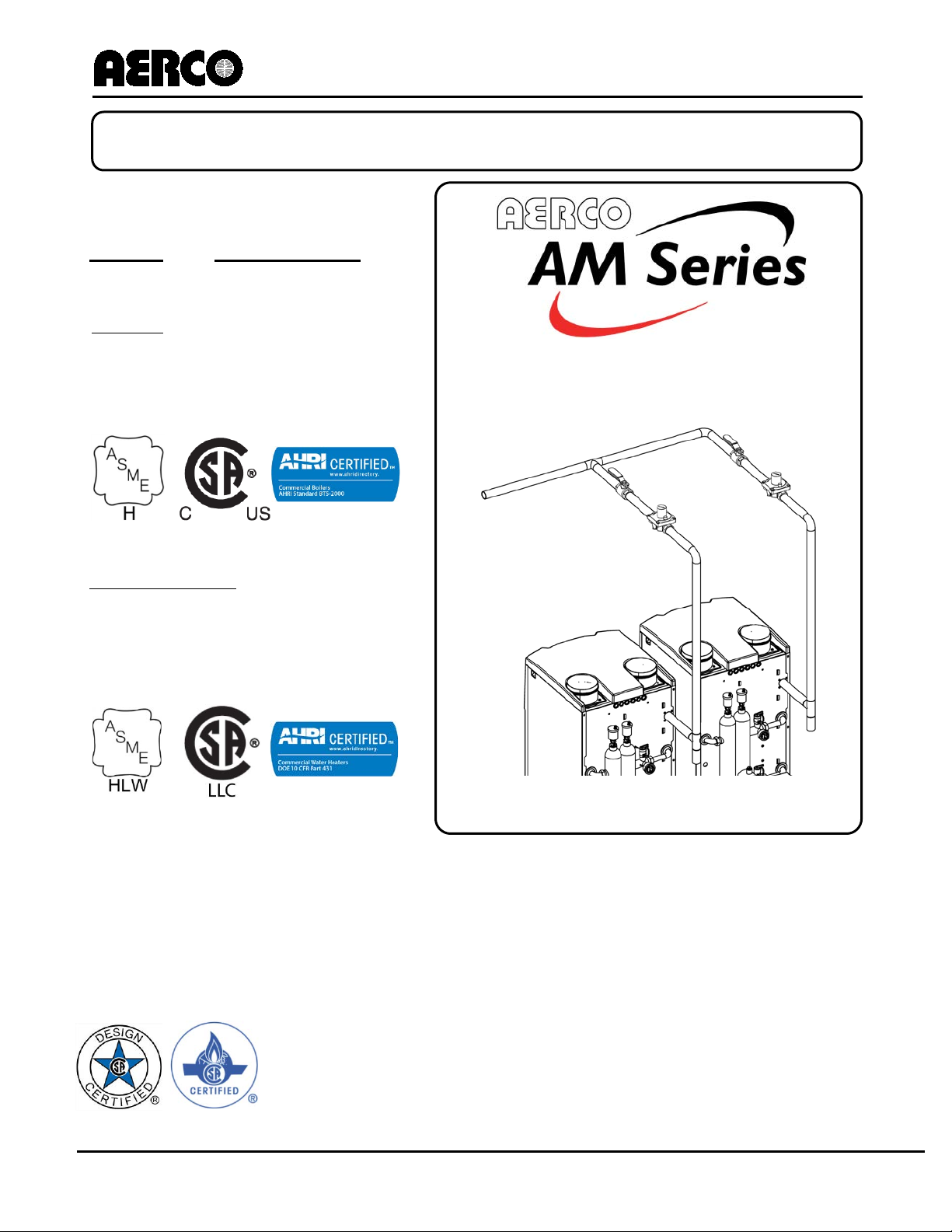
AM Gas Supply Piping Example
Page 1 of 8 AERCO International, Inc. • 100 Oritani Dr. • Blauvelt, New York 10913 • Phone: 800-526-0288 PR1 04/08/2014
Page 2
AM Series Gas Supply
Application Guide
GF-146-G
TAG-0073_0B
Technical Support:
(Mon–Fri, 8am-5pm EST)
1 (800) 526-0288
DISCLAIMER
The information contained in this manual is subject to change without
notice from AERCO International, Inc. AERCO makes no warranty of any
kind with respect to this material, including, but not limited to, implied
warranties of merchantability and fitness for a particular application.
AERCO International is not liable for errors appearing in this manual, for
incidental or consequential damages occurring in connection with the
furnishing, performance, or use of these materials.
Table of Contents
Table of Contents ..................................................................................... 2
1. GENERAL INTRODUCTION .............................................................. 3
2. GAS TRAIN COMPONENTS .............................................................. 3
3. GAS PRESSURE REQUIREMENTS ................................................... 3
4. GAS PIPING ...................................................................................... 4
5. GAS SUPPLY MAIN SIZING.............................................................. 5
6. GAS HEADER SIZING ....................................................................... 5
PR1 04/08/2014 AERCO International, Inc. • 100 Oritani Dr. • Blauvelt, New York 10913 • Phone: 800-526-0288 Page 2 of 8
Page 3
GF-2060
TAG-0073_0B
1. GENERAL INTRODUCTION
The AERCO AM Series gas fired boilers and water heaters are modulating input boilers that require
an adequate volume and pressure of natural or propane gas for proper operation. The gas
requirements specified herein must be satisfied to ensure efficient combustion. Designers and
installers must adhere to the specifications of AERCO and of the local authorities having jurisdiction.
A thorough understanding and knowledge of these guidelines is required for the successful design
and installation of AM Series boilers and water heaters.
2. GAS TRAIN COMPONENTS
The AM Series unit is a stainless steel modular boiler consisting of individual combustion chambers,
each having its own gas train (gas valve, pre-combustion chamber, and burner), blower, check valve,
igniter, and flame detector, but connected to a common flue. Each group of these components is
referred to as a module. The gas train components have been designed to operate at high combustion
and seasonal efficiencies by closely controlling both the volume and air/fuel mixture to the burner.
Below are descriptions of each of the gas train components for each module.
• GAS VALVE – An electronic, modulating gas valve with 100% tight shutoff. It controls the
amount of gas delivered to the burner.
• MODULATING PRE-MIX BLOWER – A variable speed blower mounted to the combustion
chamber, where combustion air and gas mix prior to entering the burner, providing controlled
combustion. The outlet of the blower leads to a check valve, which prevents any backflow of
combustion gases.
• LOW NOx BURNER – A metal fiber mesh covers a stainless steel burner head on which
combustion occurs. The burner operation is stable throughout the entire input range of the
boiler.
3. GAS PRESSURE REQUIREMENTS
The AERCO AM Series of boilers and water heaters require a stable gas input pressure. The inlet
supply to the unit must be at least 3 “ W.C. when firing at maximum input. Maximum allowable gas
pressure is 13” W.C. Static gas pressure (when the unit is not firing) may vary, however actual gas
pressure should be measured when the unit is in operation (firing). Measure the gas pressure with a
manometer at the port provided in the gas valve. In a multiple boiler installation, gas pressure should
initially be set for a single boiler in operation and then remaining boilers should be staged on at full
fire to ensure that gas pressures never fall below the minimum allowable pressure of 3” W.C.
An external gas pressure regulator is mandatory for the State of Massachusetts, regardless of supply
pressure; for all other jurisdictions, a lock-up style regulator is required when supply pressure is
greater than 13” W.C. (see Fig. 1). The regulator must be installed with at least 2 feet of pipe
between the regulator and the unit gas inlet. The regulator discharge range must able to maintain 3”
W.C. Gas regulators are self-contained with tapped diaphragm vent ports allowing the diaphragm to
change its position. These vents typically require piping to the outside.
Every AM unit requires a manual shutoff valve. CSA requires that no other components can be installed
between the boiler and this shutoff valve except for pipe fittings such as a pipe union. If an external
regulator is used, an additional isolation/service valve must be installed upstream of the regulator (see
Figure 1). Gas piping should contain ground unions for removal of the gas piping to the unit for
maintenance or service as required. Gas piping should never obstruct removal of the unit side panels
and should not be supported from the unit itself. Gas piping should be supported properly from the floor
or overhead as the installation allows.
PR1 04/08/2014 AERCO International, Inc. • 100 Oritani Dr. • Blauvelt, New York 10913 • Phone: 800-526-0288 Page 3 of 8
Page 4

AM Series Gas Supply
Application Guide
GF-146-G
TAG-0073_0B
GAS SUPPLY LINE:
CAUTION!
The unit must be isolated from the system when leak testing the
gas piping.
Drip legs are typically required at the gas supply of each unit to prevent any dirt, weld slag, or debris
from entering the boiler gas train inlet pipe. When multiple units are installed, some utilities and local
codes require a full size drip leg on the main gas supply line in addition to the drip leg at each unit. The
bottom of the gas drip leg(s) should be removable without disassembling any gas piping. The weight of
the gas pipe should not be supported from the bottom of the drip leg. The drip leg(s) should not be used
to support any or part of the gas piping.
GAS PRESSURE
REGULATOR
MANUAL GAS
SHUT-OFF VALVE
MAINTAIN AT LEAST 3” W.C.
NATURAL GAS PRESSURE AT
MAXIMUM BTU/HR INPUT
DRIP LEG
Figure 1: Single Boiler Gas Pipe Connections
4. GAS PIPING
All gas piping and components must comply with NFPA local codes, and utility requirement
minimums. Only gas approved fittings, valves, and pipe should be utilized.
Standard industry practice for gas piping is Schedule 40 iron pipe and fittings. All high and low gas
pressure piping systems must comply with local utility and building codes.
Assembled piping should be clean of all debris, pipe chips, or foreign material to prevent any from
entering the unit’s boiler gas train. Piping should be tested as prescribed in NFPA 54. Equipment
should be isolated before testing any piping system over the allowable pressure. DO NOT EXCEED
13” W. C. on the inlet side of the unit at any time.
PR1 04/08/2014 AERCO International, Inc. • 100 Oritani Dr. • Blauvelt, New York 10913 • Phone: 800-526-0288 Page 4 of 8
Page 5

AM Series Gas Supply
Application Guide
GF-146-G
TAG-0073_0B
5. GAS SUPPLY MAIN SIZING
1-1/4”
1-1/2”
4”
5”
The fuel supplier, or utility, should be consulted to confirm that sufficient volume and normal pressure is
provided to the building at the discharge side of the gas meter or supply pipe. For existing installations
with gas equipment, gas pressure should be measured with a manometer to ensure sufficient pressure
is available. Before sizing gas piping, a survey of all connected gas devices should be made. Gas
piping supplying more than one gas device must be able to handle the total connected input within
the allowable gas pressure drop. The allowable minimum and maximum gas pressure for each device
should be considered. Whenever the minimum and maximum gas pressures vary between devices,
gas pressure regulators at each unit should be installed to allow regulation at any individual unit. Gas
pressure must never exceed the maximum allowable rating of any connected device.
The total length of gas piping as well as fitting pressure drop must be considered when sizing the gas
piping. Total equivalent length should be calculated from the meter or source location to the last unit
connected. Gas piping Table 1, containing data extracted from NFPA 54, should be used as a
minimum guideline. Gas pipe size should be selected on the total equivalent length from the table.
The gas volume for cfh flow will be the input divided by the calorific value of the fuel to be supplied.
Table 1: Gas Supply Main Piping Minimum Size Requirements
Maximum Capacity of Pipe in Cubic Feet of Gas / Hour
(Gas pressure = 0.5 psig or less, pressure drop = 0.5 inches of w. c.)
(Natural Gas with Specific Gravity of 0.60)
Nominal
Iron Pipe
Size
2”
2-1/2”
3”
10’ 20’ 30’ 40’ 60’ 80’ 100’
1,390 957 768 657 528 452 400
2,090 1,430 1,150 985 791 677 600
4, 020 2,760 2,220 1,900 1,520 1,300 1,160
6,400 4,400 3,530 3,020 2,430 2,080 1,840
11,300 7,780 6,250 5,350 4,290 3,670 3,260
23,100 15,900 12,700 10,900 8,760 7,490 6,640
41,800 28,700 23,000 19,700 15,800 13,600 12,000
Length of Pipe in Feet
NOTE
For further information refer to the latest edition of the National Fuel
Gas Code Handbook, ANSI Z223.1
6. GAS HEADER SIZING
Main supply gas pipe sizing should be developed for the total plant. Boiler gas manifold piping should be
sized based on the volume requirements and lengths between boilers and the fuel main. Header sizes
can be either full size or stepped in size as units are connected. A typical gas piping header diagram for
two AERCO AM Series boilers is illustrated in Figure 2. Header should be located above or behind
boiler. Gas piping should not be installed directly over top or front of any part of boiler.
PR1 04/08/2014 AERCO International, Inc. • 100 Oritani Dr. • Blauvelt, New York 10913 • Phone: 800-526-0288 Page 5of 8
Page 6

AM Series Gas Supply
Application Guide
GF-146-G
TAG-0073_0B
MANUAL GAS
VALVE #2
MANUAL GAS
VALVE #1
SHUT-OFF
SHUT-OFF
GAS PRESSURE
REGULATOR #2
GAS PRESSURE
REGULATOR #1
GAS SUPPLY LINE:
MAINTAIN AT LEAST
3” W.C. NATURAL
GAS PRESSURE AT
MAXIMUM BTU/HR
INPUT
DRIP
DRIP
LEG #2
LEG #1
Figure 2: Typical Multiple Boiler Gas Manifold Construction
Ensure proper clearances for maintenance. Piping should not interfere with the removal of the unit’s
covers nor impede maintenance. Observe service clearances around the boiler as listed below and as
shown in Figures 3 and 4:
PR1 04/08/2014 AERCO International, Inc. • 100 Oritani Dr. • Blauvelt, New York 10913 • Phone: 800-526-0288 Page 6 of 8
• TOP of the boiler: 20‘‘ (500 mm)
• FRONT of the boiler: 31.5’’ (1000 mm)
• RIGHT side: 4’’ (100 mm)
• LEFT side: 4’’ (100 mm)
• BACK of the boiler: 20’’ (500 mm)
Page 7

AM Series Gas Supply
Application Guide
GF-146-G
TAG-0073_0B
Figure 3: AM 399/500 Clearances
FRONT VIEW
SIDE VIEW
FRONT VIEW
SIDE VIEW
PR1 04/08/2014 AERCO International, Inc. • 100 Oritani Dr. • Blauvelt, New York 10913 • Phone: 800-526-0288 Page 7of 8
Figure 4: AM 750/1000 Clearances
Page 8

AM Series Gas Supply
Application Guide
GF-146-G
TAG-0073_0B
www.aerco.com
Change Log:
Date Description Changed By
04/08/2014 Rev A: Release Curtis Harvey
PR1 04/08/2014 AERCO International, Inc. • 100 Oritani Dr. • Blauvelt, New York 10913 • Phone: 800-526-0288 Page 8 of 8
© AERCO International, Inc., 2014
 Loading...