

Page 1
QIG-0001_0A • 11/1/2019 Technical Support • (800) 526-0288 • Mon-Fri, 8 am - 5 pm EST Page 1 of 7
Max. TDS
< 200 ppm
Chloride
< 150 ppm
Conductivity
< 3000 μS
pH
7.5-9.5
WARNING!
Follow all provisions, warnings, and cautions provided in the AM boiler/water heater Operations and Maintenance (O&M) manuals. Failure to
comply with the O&M can lead to extensive property damage and/or personal injury or death.
Do not store any flammable materials or liquids in the immediate vicinity of the unit.
Provisions for sufficient combustion air and ventilation of the boiler room are required (see O&M for details).
Liquefied petroleum gas-burning appliances shall not be installed in a pit, basement or similar location where heavier-than-air-gas might
collect.
The unit installation and startup must be carried out by trained and qualified professionals.
MASSACHUSETTS INSTALLATIONS: Installer must be licensed within the Commonwealth of Massachusetts. Unit must be installed according to
all local codes. See O&M manual for more information.
In the event of a breakdown and/or malfunction of the unit, turn it off and do not make any attempt to repair it; service must be performed
by a certified service technician using original spare parts.
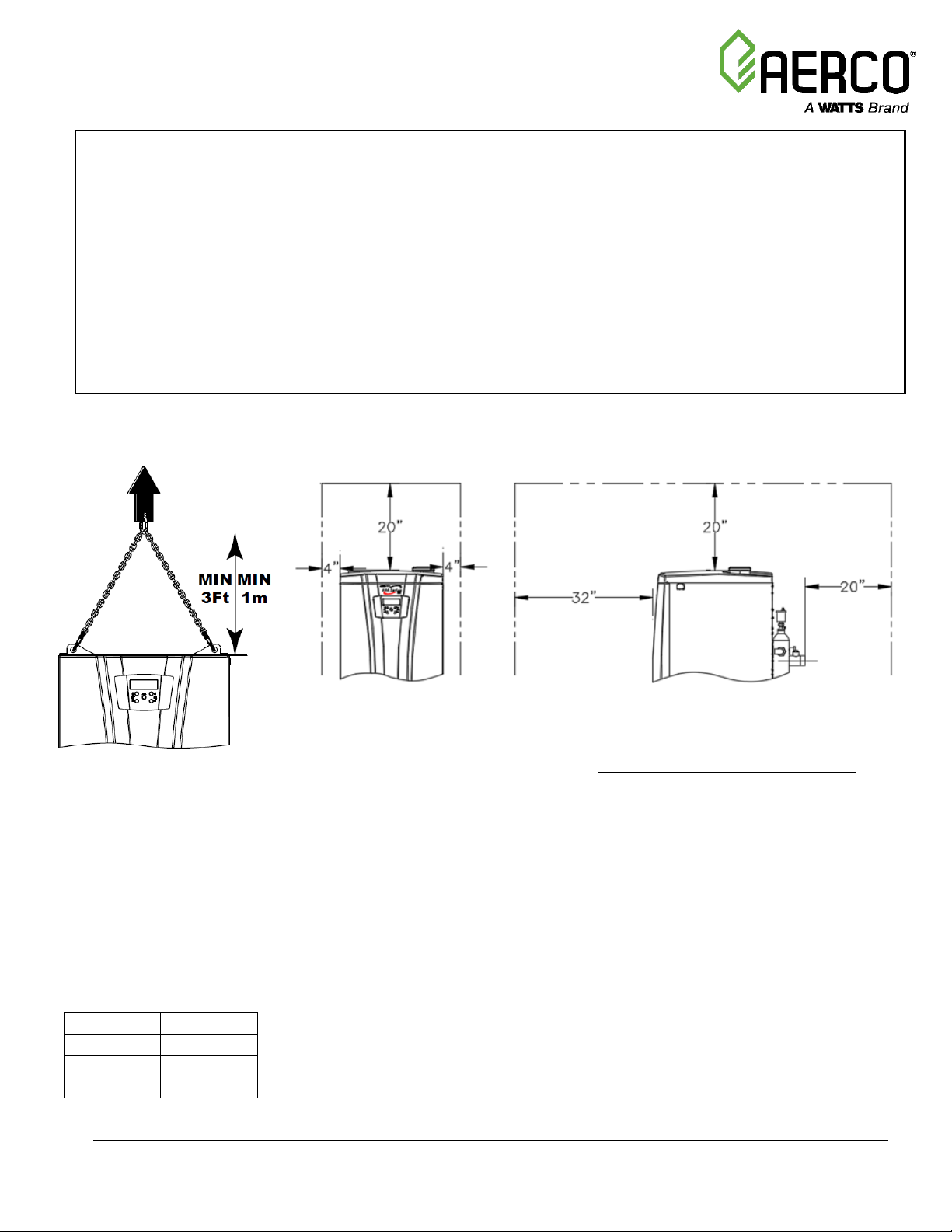
Transport, Installation Requirements
CORRECT WAY TO LIFT UNIT:
INSTALLATION CLEARANCES
Accessories Included (inside
unit):
(1) Gas to LP conversion kit
(1) Remote temperature sensor
(2) Spare vent thermal fuses
(1) Neutralizer media
(4) Adjustable foot
(1) Outdoor sensor-boiler models only
(1) Piping kit for circulation pump—
(AMRI models only; shipped loose)
ALCOVE/CLOSET INSTALLATIONS:
Follow rules on clearances, venting, ventilation openings as per the O&M and the National Fuel Gas Code, ANSI
Z223.1/NFPA 54 and/or CAN/CSA B149.1, Natural Gas and Propane Installation Code and local codes. DO NOT use
non-metallic exhaust pipe material into a closet or alcove; the only exhaust pipe material accepted is AL29-4C.
COMBUSTION AIR REQUIREMENTS:
The combustion air must be free of chlorine, halogens or any other chemicals that are detrimental to the operation
of the unit. Sufficient air supply must be provided to support room air combustion - see O&M and Venting
Applications Guide GF-146-V for details.
GAS PRESSURE REQUIREMENTS:
• The inlet supply to the unit must be at least 3” W.C. when firing at maximum input. Maximum allowable gas pressure
is 13”W.C.
• A lock-up style external gas regulator is required when supply pressure is greater than 13” W.C.
• External gas regulator is required for State of Massachusetts, regardless of supply pressure.
• Unit is factory shipped for Natural Gas operation. For Propane operation, see O&M for conversion instructions.
WATER CHEMISTRY:
• Do NOT use artificially softened water
• Consult chemical manufacturer for certification of inhibitor, anti-freeze, etc. used for hydronic systems
• For best results, clean hydronic system before adding inhibitors; isolate boiler from piping during system flushing
Water Chemistry
Allowable Limits:
AM Series Quick Installation Guide
Page 2
Quick Installation Guide
AM Series
QIG-0001_0A • 11/1/2019 Technical Support • (800) 526-0288 • Mon-Fri, 8 am - 5 pm EST Page 2 of 7
Equivalent Pipe Lengths
Diam
Sharp 90°
Sweep 90°
45°
AM 199/250
3”
10 ft.
5 ft.
5 ft.
AM 399/500
4”
10 ft.
5 ft.
5 ft.
AM 750/1000
6”
10 ft.
5 ft.
5 ft.
Exh Outlet
Duravent PolyPro
AM 199/250
3”
3PPS-03PVCM-3PPF
AM 399/500
4”
4PPS-04PVCM-4PPF
AM 750/1000
6”
6PPS-06PVCM-6PPF
Centrotherm Innoflue
(PP)
AM 199/250
3”
ISAAL03
AM 399/500
4”
ISAAL04
AM 750/1000
6”
ISAAL06
Security Chimneys (Al29-
4C)
AM 199/250
3”
SS3PVCU
AM 399/500
4”
SS4PVCU
AM 750/1000
6”
SS6PVCU
Security Chimneys DW
(Al29-4C)
AM 199/250
3”
SS3PVCUK
AM 399/500
4”
SS4PVCUK
AM 750/1000
6”
SS6PVCUK
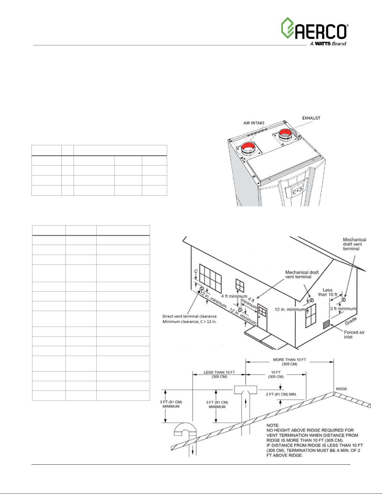
Venting/Air Intake
ACCEPTABLE MATERIALS
• Acceptable vent materials: Al29-4C Stainless Steel, Polypropylene, CPVC, PVC. For Alcove/Closet Installation, use Al29-4C only.
• Do not use PVC exhaust for applications where return water temperature > 145F. See O&M for additional information.
• Polypropylene and Al29-4C exhaust requires additional adapters - contact the vent manufacturer for suitable adapter.
VENT/AIR INTAKE SIZING:
• Maximum length of vent is 60 equivalent ft.
• Maximum length of air intake is 60 equivalent ft.
• For manifolded vents, see O&M manual
Exhaust Adapter supplied with unit accepts
PVC. When using polypropylene or Al29-4C
exhaust, additional adapter required—
example manufacturers:
VENT TERMINATION
Page 3

Quick Installation Guide
AM Series
QIG-0001_0A • 11/1/2019 Technical Support • (800) 526-0288 • Mon-Fri, 8 am - 5 pm EST Page 3 of 7
POTABLE APPLICATIONS
MINIMUM FLOW
10 grains/gal max
200ppm TDS max
POTABLE APPLICATIONS
MINIMUM FLOW
18 grains/gal max
200ppm TDS max
AM 199
11 gpm
18 gpm
AM 250
12 gpm
18 gpm
AM 399
22 gpm
37 gpm
AM 500
24 gpm
37 gpm
AM 750
36 gpm
60 gpm
AM 1000
48 gpm
75 gpm
WATER PIPING:
Boiler applications:
• Use primary/secondary piping configuration.
• Common pipe diameter must be sized for less than 4.0 ft/sec; common pipe length must
be 3 to 5 times its diameter.
• Single unit application - relocate supply temperature sensor from boiler header to system
piping.
• Multiple unit application - install Cascade header temperature sensor in the system piping
(see AERCO Cascade Sequencer user manual (GF-146-CS) for installation details).
Water heating applications:
• A storage tank must be used. See below for basic
piping configurations.
• An anti-scald valve must be used and installed in
accordance with local codes.
Ensure that the minimum system flow is met
per chart and table below, otherwise the flow
sensors will automatically stop the burner.
AM SERIES PRESSURE DROP
A: AM 199/250; Min flow (high fire) =11 gpm/ 12 gpm
B: AM 399; Min flow (high fire) =22 gpm
C: AM 500; Min flow (high fire) =24 gpm
D: AM 750; Min flow (high fire) =36 gpm
E: AM 1000; Min flow (high fire) =48 gpm
Page 4

Quick Installation Guide
AM Series
QIG-0001_0A • 11/1/2019 Technical Support • (800) 526-0288 • Mon-Fri, 8 am - 5 pm EST Page 4 of 7
BOILER APPLICATIONS
WATER HEATING APPLICATIONS
(with Integrated Tank)
The condensate drain must
slope down and away from
the boiler into a drain; it
must be installed accordingly
in order to avoid the freezing
of the liquid.
WATER HEATING APPLICATIONS
(Separate Tank)
Page 5

Quick Installation Guide
AM Series
QIG-0001_0A • 11/1/2019 Technical Support • (800) 526-0288 • Mon-Fri, 8 am - 5 pm EST Page 5 of 7
Install a 15 am fused disconnect or service switch. (15 amp). All electrical conduit and hardware should be installed so that it does not interfere with
the removal of any cover, inhibit service or maintenance, or prevent access between the unit and walls or another unit.
All AM Series pump relays are rated for 3A max. When pumps used exceed 3A, an appropriately sized external relay or starter must be used.
CONNECTING UNITS IN CASCADE:
Up to eight boilers or water heaters may be combined in a cascading
system using the optional Cascade Sequencer. Refer to the AERCO
Cascade Sequencer user manual (GF-146-CS) for installation details.
MODBUS INTERFACE CONNECTIONS:
The AM unit can be controlled from a building management system via MODBUS
interface. This requires a Communication Module on each unit (AM399-1000: factory
installed; AM199/250: optional). Refer to the AM Series MODBUS User Manual (GF146-MB) for wiring and setup details.
Electrical/Controls Wiring - BOILER
To program the settings indicated below, see Page
6 for control panel button functions.
• Main Power supply: Terminals 101/102/PE
• Low Water Cut Off: Terminals 103/104
• Primary Pump (boiler loop): Terminals
113/114
• Constant Setpoint Enable/Disable (if
employed; otherwise jumped): Terminals
10/11
Set Para. 2003=0
• Outdoor Sensor (if employed): Terminals
14/15
Set Para. 2003=1 (Outdoor Reset)
See O&M for additional settings for Outdoor Reset
• 0-10VDC (if employed): Terminals 22/23
Set Para. 2003=4 (0-10V)
Notes on 0-10VDC analog input:
- analog input drives the supply
temperature
- requires a Communication Module on
each unit (AM399-1000: factory
installed; AM199/250: optional).
-
See O&M for additional settings when
controlling via 0-10VDC.
•
Indirect Fired heater sensor (if employed) *:
Terminals 12/13
Set Para. 3012=1
See O&M for additional settings for Indirect
Fired Water Heating
• Indirect Fired heater pump: Terminals
107/108
• Secondary Pump (system loop): Terminals
105/106
BOILER APPLICATION Basic Wiring and Settings:
STARTUP PRECEDURE - BOILER APPLICATION
(Prior to startup, see page 7 for Combustion Calibration)
1. Open the manual gas shutoff valve.
2. Turn power switch ON
3. Change heating setpoint: C/A. Press B to save.
4. If an indirect water heater is connected use R/S to change
domestic hot water temperature. Press B to save.
NOTE: If the burner fails to ignite within 60 seconds, the
boiler will attempt ignition another four times. Consult O&M
manual if the boiler reaches a lockout condition after four
ignition retries.
Page 6

Quick Installation Guide
AM Series
QIG-0001_0A • 11/1/2019 Technical Support • (800) 526-0288 • Mon-Fri, 8 am - 5 pm EST Page 6 of 7
Electrical/Controls Wiring - WATER HEATER
Install a 15 am fused disconnect or service switch. (15 amp). All electrical conduit and hardware should be installed so that it does not interfere with
the removal of any cover, inhibit service or maintenance, or prevent access between the unit and walls or another unit.
All AM Series pump relays are rated for 3A max. When pumps used exceed 3A, an appropriately sized external relay or starter must be used.
WATER HEATER APPLICATION
Basic Wiring and Settings:
• Main Power supply: Terminals 101/102/PE
• Low Water Cut Off: Terminals 103/104
• Storage tank pump: Terminals 113/114
• Storage tank sensor: Terminals 8/9
(replace factory installed header sensor)
Set Para. 2003=0
STARTUP PRECEDURE - WATER HEATER APPLICATION
(Prior to startup, see page 7 for Combustion Calibration)
1. Open the manual gas shutoff valve.
2. Turn power switch ON
3. Change storage tank water temperature: C/A. Press B to save.
NOTE: If the burner fails to ignite within 60 seconds, the boiler will
attempt ignition another four times. Consult O&M manual if the
boiler reaches a lockout condition after four ignition retries.
CONNECTING UNITS IN CASCADE:
Up to eight boilers or water heaters may be combined in a cascading system using
the optional Cascade Sequencer. Refer to the AERCO Cascade Sequencer user
manual (GF-146-CS) for installation details.
MODBUS INTERFACE CONNECTIONS:
The AM unit can be controlled from a building management system via MODBUS interface. This requires a Communication Module on each unit
(AM399-1000: factory installed; AM199/250: optional). Refer to the AM Series MODBUS User Manual (GF-146-MB) for wiring and setup details.
Controls Panel Button Functions
To access Installer Menu (Para 2000’s):
Hold B and S (5 seconds) until G appears.
Scroll through parameters: R/S
Select parameter: B (value blinks)
Change parameter value: R/S
Confirm new value: B
Exit Installer Menu: Hold B (>5 seconds) until G disappears.
To access Factory Menu (Para 3000’s):
Turn power switch to OFF.
Hold B and S, turn power switch ON, wait until “init” is displayed.
Release B then release S.
Select parameter: B (value blinks)
Change parameter value: R/S
Confirm new value: B
Exit Installer Menu: Wait min. 10 seconds. Turn power switch to
OFF. Turn power switch ON.
A - Setpoint Button (–): lowers the heating setpoint.
B - Multifunction button: resets any lockouts; accesses user and installer menus.
C - Setpoint Button (+): raises the heating setpoint.
D – Flame icon: indicates that a flame is present .
E - Radiator icon. indicates that a heating service is enabled. Blinks when heating service is active.
H - Unit of measure of the pressure (M).
F - Faucet icon: Indicates that the domestic hot water service is enabled. Blinks when domestic hot water service is active.
L - Burner unit indicators: Lights up when burner is burning; blinks when burner is in lockout or has a block ing error.
M - Pressure gauge and parameter display.
G - Gear icon: indicates access to the installer menu.
N - Supply or indirect water heater temperature gauge and display of parameter values.
0 - Unit of measure of the temperature (N).
P - Sensor icon: indicates that the outdoor sensor is active.
R - Multifunction button (+): raises the domestic hot water temperature;
scrolls through parameters; increases
parameter values.
S - Multifunctional button ( –): lowers the domestic hot water temperature;
scrolls through parameters; decreases
parameter values.
T - On-Off power switch.
Page 7

Quick Installation Guide
AM Series
QIG-0001_0A • 11/1/2019 Technical Support • (800) 526-0288 • Mon-Fri, 8 am - 5 pm EST Page 7 of 7
Combustion Calibration
GAS SUPPLY PRESSURE TEST
1. Close the manual gas shutoff valve.
2. Remove the front cover.
3. Turn inlet pressure port D screw three turns CCW.
4. Connect manometer to port D.
5. Open the manual gas shutoff valve.
6. Check gas pressure does not exceed 13” W.C. Adjust upstream
gas regulator as needed.
7. Turn power switch ON.
8. Generate heat demand: press C (boiler/water heater) or R
(indirect water heater) to its maximum setting.
9. Set Para 2200 (AM 399-1000) or 2010 (AM 199/250) to HIGH
10. Check gas pressure is between 3”-13” W.C. Adjust upstream
gas regulator as needed.
11. Return Para. 2200 or 2010 to OFF
COMBUSTION CALIBRATION
1. Follow vent pipe manufacturer’s instruction to install combustion analyzer probe 8” after the flue gas exhaust connection.
2. Start unit per procedure on this page.
3. Set unit to standby: Press A (boiler) or S (water heater) until “OFF” is displayed
4. Set Para 2201 (AM 399-1000) or 2010 (AM 199/250) to HIGH
5. Generate demand: Press C (boiler) or R (water heater) until setpoint is above “OFF” (e.g. 90F)
6. Wait 2-3 min. for CO2 to stabilize.
7. Compare CO2 reading with high fire range in Table below, making sure to use the range for gas type in use. If CO2 reading is outside the range,
use screw E (2.5mm Allen) to adjust: CW to reduce CO2, CCW to increase CO2. Adjust in small increments and wait for CO2 to stabilize in between
readings.
8. Set Para 2201 OR 2010 to LOW.
9. Wait 2-3 min. for CO2 to stabilize.
10. Compare CO2 reading with low fire range in Table below, making sure to use the range for gas type in use. If low fire CO2 reading is outside the
range, STOP the unit and call the Factory service department.
11. Set Para. 2201 or 2010 to OFF.
12. AM 399-1000: repeat steps 3-9 for burners 2, 3 and 4 as applicable, using parameters 2202-2204 to calibrate each burner in turn.
13. Close the combustion analyzer probe.
 Loading...