

Page 1

55
Di
R
f
t
”
shafts
I
nstallation Instruction
s
Q
n
1
I
.
I
.
.
3
.
4
.
N
.
.
uick-Mount Visual Instructions for Mechanical Installatio
Quick-Mount Visual Instructions
. Rotate the damper to its fail-safe position.
f the shaft rotates counterclockwise, mount the “CCW” side of the actuator out
f it rotates clockwise, mount the actuator with the “CW” side out
2. If the universal clamp is not on the correct side of the actuator, move it to the correct side
. Slide the actuator onto the shaft and tighten the nuts on the V-bolt with a 10mm wrench to 6-8 ft-lb of torque
. Slide the anti-rotation strap under the actuator so that it engages the slot at the base of the actuator. Secure the strap to the duct work with #8 self-tapping screws
OTE: Read the “Standard Mounting” instructions, on the next page, for more detailed information
mensions (Inches [mm])
min. 3 1/2"
[90]
min. 3/4"
[20]
IND-AF2 Position Indicator
(optional)
emove
or 3/4”
o 1.05
IND-AF2 Position Indicator
(optional)
M40024 - 05/10 - Subject to change. © Belimo Aircontrols (USA), Inc
800-543-9038 USA 866-805-7089 CANADA 203-791-8396 LATIN AMERICA
Page 2
56
Installation Instruction
s
M
n
p
f
g
,
f
s
.
P
f
s
.
,
f
s
.
,
f
s
.
p
t
.
T
t
Beli
f
enclosure must be used to shield
,
t
s
T
y
shaf
-
saf
sy
T
T
i
T
d
s
T
c
p
f
f
p
-
off
d
a
.
1
rotated counterclockwise (
), this is a CCW installation. If the shaft rotated
)
clockwise (
), this is a CW installation. In a CCW installation, the actuator side
)
All
l.
2
s
s
c
Short Shaft Installation
section.
3
c
u
p
C
)
S
Limiting, Mechanical Minimum Damper Position
4. Lock th
5
6. Slide
.
desired locatio
f
9
p
f
.
echanical Installatio
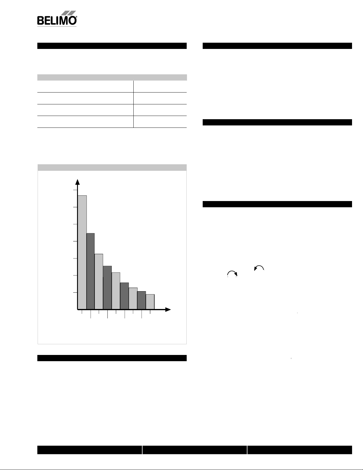
Determining Torque Loading and Actuator Sizing
Damper torque loadings, used in selecting the correct size actuator, should be
rovided by the damper manufacturer. If this information is not available, the
ollowing general selection guidelines can be used.
Damper Type Torque Loadin
Opposed blade, without edge seals
or non-tight close-off application
arallel blade, without edge seals,
or non-tight close-off application
Opposed blade, with edge seals
or tight close-off application
Parallel blade, with edge seals
or tight close-off application
The above torque loadings will work for most applications under 2 in. w.g. static
ressure or 1000 FPM face velocity. For applications between this criteria and 3 in.
w.g. or 2500 FPM, the torque loading should be increased by a multiplier of 1.5. If
he application calls for higher criteria up to 4 in. w.g. or 3000 FPM, use a multiplier
of 2.0
3 in-lb/sq. ft
4 in-lb/sq. ft
5 in-lb/sq. ft
7 in-lb/sq. ft
orque Loading Char
70
60
50
40
30
Mechanical Operation
he actuator is mounted directly to a damper shaft up to 1.05” in diameter b
means of its universal clamp. A crank arm and several mounting brackets are
available for applications where the actuator cannot be direct coupled to the damper
t. The AF series actuators provide true spring return operation for reliable fail
e application and positive close-off on air tight dampers. The spring return
stem provides constant torque to the damper with, and without, power applied to
the actuator. The AF…-S versions are provided with 2 built-in auxiliary switches.
hese SPDT switches are provided for safety interfacing or signaling, for example,
for fan start-up. The switching function at the fail-safe position is fixed at +5°, the
other switch function is adjustable between +25 to +85°.
Automatic Airtight Dampers/Manual Override
he AF series provides 95° of rotation and is provided with a graduated position
ndicator showing 0° to 95°.
he AF has a unique manual positioning mechanism which allows the setting of any
amper position within its 95° of rotation. A pre-tensioned spring automatically
tightens damper when power is applied to the actuator, compensating for damper
eal deterioration.
he actuator is shipped at +5° (5° from full fail-safe) to provide automatic
ompression against damper gaskets for tight shut-off. When power is applied, the
manual mechanism is released and the actuator drives toward the full fail-safe
osition.
Standard Mounting
NOTE: The AF…series actuator is shipped with the manual override adjusted
or a +5° position at the universal clamp (not at full fail-safe, 0°). This allows
or automatic compression of damper blade seals when the actuator is in use,
roviding tight shut-off. This assumes that the damper is to have tight shut
at the fail-safe position. If tight close-off is desired at the opposite
irection from fail-safe, the manual override should be released so the
ctuator can go to the full fail-safe position. See the manual override
instructions
. Manually move the damper to the fail-safe position (usually closed). If the shaft
Damper Area (sq. ft.)
20
10
0
2
46810
3
579
Torque Loading (in-lb/
sq. ft.)
General Information
mo actuators should be mounted indoors in a dry, relatively clean environment
ree from corrosive fumes. If the actuator is to be mounted outdoors, a protective
M40024 - 05/10 - Subject to change. © Belimo Aircontrols (USA), Inc.
For new construction work
installing contractor to allow space for mounting and service of the Belimo actuator on
he shaft. The damper shaft must extend at least 3 1/2” from the duct. If the shaft
extends less than 3-1/2” or if an obstruction blocks access, the shaft can be extended
with the AV 10-18 shaft extension accessory or the actuator may be mounted in its short
haft configuration.
the actuator.
order dampers with extended shafts. Instruct the
marked “CCW” faces out, while in a CW installation, the side marked “CW” faces
other steps are identica
out.
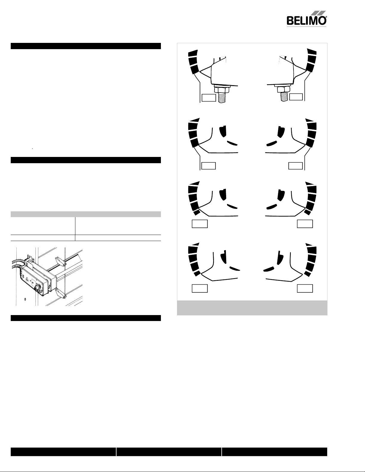
. The actuator is usually shipped with the universal clamp mounted to the “CCW”
ide of the actuator. To test for adequate shaft length, slide the actuator over the
haft with the side marked “CCW” (or the “CW” side if this is the side with the
lamp). If the shaft extends at least 1/8” through the clamp, mount the actuator
as follows. If not, go to the
. If the clamp is not on the correct side as determined in step #1, re-mount the
lamp as follows. If it is on the correct side, proceed to step #5. Look at the
niversal clamp. If you are mounting the actuator with the “CCW” side out,
osition the clamp so that the pointer section of the tab is pointing to 0° (see
Figure
and the spline pattern of the clamp mates with spline of the actuator.
lip the clamp over the spline. (Use the same procedure if the “CW” side is out.) If
your application requires a mechanical minimum position, read theRotation
e clamp to the actuator using the retaining clip.
. Verify that the damper is still in its full fail-safe position.
the actuator over the shaft
7. Position the actuator in the
8. Tighten the two nuts on the clamp using a 10mm wrench or socket using 6-8
t-lb of torque.
. Slip the stud of the anti rotation strap into the slot at the base of the actuator.
The stud should be positioned approximately 1/16 of an inch from the closed end
of the slot. Bend the stra
duct with #8 sel
as needed to reach the duct. Attach the strap to the
tapping screws
section.
n.
800-543-9038 USA 866-805-7089 CANADA 203-791-8396 LATIN AMERICA
Page 3
57
30
20
10
0
CCW
30
20
10
0
-5
40
30
20
10
0
-5
40
30
20
10
0
-5
-5
-5
-
FIGU
p
s
I
nstallation Instruction
s
M
ion
I
:
1
T
t
.
.
3
4
.
6. Positi
.
f
8
T
9
Fig
T
d
m
g
details.
T
M
ft
A
S
A
S
A
S
4
A
f
o
sed
If
m
NO
ppli
S
e
.
echanical Installat
Short Shaft Installation
f the shaft extends at least 3/4” from the duct, follow these steps
. Determine the best orientation for the universal clamp on the back of the actuator.
he best location would be where you have the easiest access to the V bolt nuts on
he clamp
2. Engage the clamp to the actuator as close as possible to the determined location
. Lock the clamp in place using the remaining retainer clip.
. Verify that the damper is still in its full fail-safe position
5. Slide the actuator over the shaft.
on the actuator in the desired location
7. Tighten the two nuts on the clamp using a 10mm wrench or socket using 6-8
t-lb of torque.
. Slip the stud of the anti-rotation strap into the slot at the base of the actuator.
he stud should be positioned approximately 1/16 of an inch from the closed end
of the slot. Bend the strap as needed to reach the duct. Attach the strap to the
duct with #8 self tapping screws.
. If damper position indication is required, use the optional IND-AF2 pointer. See
ure A
Jackshaft Installation
he AF… series actuator is designed for use with jackshafts up to 1.05” in
iameter. In most applications, the AF actuator may be mounted in the same
anner as a standard damper shaft application. If more torque is required than one
AF actuator can provide, a second AF actuator may be mounted to the jackshaft
usin
the ZG-102 multiple actuator mounting bracket. See wiring guide for wiring
AF ACTUATORS WHICH MAY BE USED ON ONE SHAF
odel Maximum Quantity Per Sha
F24(-S) U
F120(-S) U
F230(-S) U
F24-SR US
MOUNTING: If the actuators are
mounted on the opposed ends of the
shaft, the actuator direction must be
selected care
f rotation is rever
ully. Usually, the direction
.
Correct clamp mounting
position if actuator is at
full fail-safe.
CW
Correct pointer mounting
position if actuator is at
full fail-safe.
CCW
40
0
3
20
10
0
Correct pointer mounting
position when actuator is
at 5° preload.
CW
30
2
0
10
0
CWCCW
0
40
30
20
10
0
Correct pointer mounting
position if actuator is at
full fail-safe.
4
30
20
10
0
Multiple Actuator Mounting
more torque is required than one AF actuator can provide, a second AF actuator
ay be mounted to the shaft using the ZG-102 multiple mounting bracket.
TE: The manual positioning mechanism cannot be used in multiple actuator
a
cations.
pecial Wiring and Additional Information: See wiring guid
800-543-9038 USA 866-805-7089 CANADA 203-791-8396 LATIN AMERICA
CWCCW
RE A – Universal Clamp and IND-AF2 Pointer (optional)
ositions indicating fail-safe and pre-load setting
M40024 - 05/10 - Subject to change. © Belimo Aircontrols (USA), Inc
Page 4

58
Rotation Limitation
u
See
Z
Limiting the d
s
r
s
.
2
C
.
s
.
4
.
5
.
7
s
M
n
r
The angle of rotation limiter, ZDB-AF2 US, is used in conjunctionwith the tab on the
niversal clamp or IND-AF2 position indicator which comes with the ZDB-AF2 US. In
order to function properly, the clamp or indicator must be mounted correctly.
Figure A.
The ZDB-AF2 US may not work in certain mounting orientations using the ZG-106 or
G-107 mounting brackets. It will not work with the ZG-108 mounting bracket.
amper rotation must be accomplished by adjusting the crank arm
linkage.
The ZDB-AF2 US may be used in 2 ways to control the rotational output of the AF
eries actuator. One use is in the application where a damper has a designed
otation less than 90°. An example would be a 45° or 60° rotating damper. The
other application would be to set a minimum damper position which can be easily
et or changed without having to remove the actuator from the damper.
Damper Rotation Limiting
1. Determine the amount of damper rotation required
. Locate the Angle of Rotation Limiter (ZDB-AF2 US) on the actuator so that its
edge lines up with the degree graduation on the actuator face which corresponds
with the required rotation. See Figure
3. Find the appropriate cross-hair location through the slot of the limiter. This is the
crew mounting location
. Pierce through the label material to allow easy fastening of the retaining screw
. Position the limiter back to the desired position, making sure the locating “teeth”
on the limiter are engaged into the locating holes on the actuator
6. Fasten the limiter to the actuator using the self tapping screw provided.
. Test the damper rotation either manually with the manual crank or apply power
and if required, a control signal. Re-adjust if necessary.
Installation Instruction
echanical Installatio
Screw secured at
these cross hairs
40
30
20
Angle of rotation
is now set at 40°.
FIGURE C – ZDB-AF2 US, Securing the Angle of Rotation Limite
Secure angle-ofrotation limiter
40
30
20
Screw
40
30
20
Philips screwdriver
M40024 - 05/10 - Subject to change. © Belimo Aircontrols (USA), Inc.
800-543-9038 USA 866-805-7089 CANADA 203-791-8396 LATIN AMERICA
Page 5

59
Installatio
n Instruction
s
n
T
e
g.
1
ocation.
3
c
.
4
direction.
- Rotate
about a 1/
-
- i
-
of arro
-
r
(
)
tu
s
“unlocked
y
s
u
sec.
T
t
m
m
.
T
f
n
o
used to
a
V
R
120
C
5
250
C
2.5A
T
.
M
F
2
adj
.
3. R
a
s
FIGU
F
M
G
p
s
.
2
a
.
3
.
es
F
.
Mechanical Installatio
Manual Override
he AF series actuators can be manually positioned to ease installation or for
mergency positionin
. The manual override will only work if no power is available to the actuator.
2. Insert the manual crank (shipped with the actuator) into the hexagon hole located
on either side of the actuator. An illustration, located on the label, shows the
l
. Turn the crank in the direction shown on the label (clockwise on the “CW” side,
ounterclockwise on the “CCW” side). It will take approximately 19 revolutions to
rotate the full 95° of rotation
. To lock the actuator in the required position, rotate the crank quickly in the opposite
direction, 1/2 of a revolution. The “lock closed” icon on the label shows the correct
5. The manual override may be disengaged in 2 ways.
the crank
winding. The “lock open” icon shows the correct direction.
Apply power to wire 1 and 2. The actuator will automatically disengage the
override function and will go to the “on” position in the case of the On/Off
versions. Or, in the case of the proportional versions, go to the 0 signal
position and then go to the position corresponding to the control signal. The
actuator will now work normally.
4 revolution in the same direction as the initial
Auxiliary Switches
he AF series actuators may be ordered with 2 built-in SPDT auxiliary switches used
or safety interfacing or signalling, for example, for fan start-up. The switch position
ear the fail-safe position is fixed at 5°. The other is adjustable between 25 and 85°
f rotation. The crank, supplied with the actuator, or a3mm allen wrench is
djust the switching position.
SWITCH RATING
oltage
VA
VA
wo methods may be used to adjust the switching point of the adjustable switch
ethod 1 - See Figure
1 The actuator must be in its fail-safe position.
. Insert the crank into the hexagon shaped hole located in the center of the
ustable switch pointer
otate the crank until the switch pointer is at the desired switch point in degrees
s shown.
AF... Serie
Factory setting 85°
40
30
50
60
70
80
25…85°
esistive Load Inductive Load
Rotate with
crank handle
40
30
50
Crank
80
25…85°
60
70
Handl
e
60° set
30
25…85°
40
A
50
60
70
80
Winding the
damper actuator
nsert crank handle
turn handle in direction
w
Locking the
damper actuator
rotate crank handle 1/2
turn in the direction
shown by the “locked”
icon.
Unlocking the
damper actuato
2 options
- rotate crank handle 1/4
rn in the direction
hown by the
” icon.
- remote control b
upplying power to the
nit for > than 3
Testing the Installation Without Power
he actuator/damper installation may be tested without power at the actuator. Refer
o the manual positioning section of the instructions. Move the damper to its full
non-fail-safe position using the manual crank. Disengage the manual position
echanism and have the damper go to full fail-safe position. Correct any
echanical problems and retest
RE
ethod 2 - See Figure
1. Position the damper to the point at which you want the switch to activate. This
may be done by using the manual override or by providing the appropriate
roportional signal to AF24… modulating type actuator. The position of the
witch pointer is not important during this step
. Insert the crank into the hexagon shaped hole located in the center of the
djustable switch pointer
. Rotate the switch pointer to just past the switch point indicating arrow as shown
AF... Seri
Actuator
after locking
40
30
50
Crank
25…85°
60
70
Handl
80
Switch operates
30
e
25…85°
40
50
60
70
80
Switch does
not operate
40
30
50
80
25…85°
60
70
IGURE G
M40024 - 05/10 - Subject to change. © Belimo Aircontrols (USA), Inc
800-543-9038 USA 866-805-7089 CANADA 203-791-8396 LATIN AMERICA
Page 6

60
KH-AF (-1) crank arm
with
KH
m
a
n
op
Installation Instruction
s
s
AF Crank a
g
The retaining clip supplied with the clamp is
used to mount the KH-AF
.
The KH-AF (-1)
dditi
AFV V-bol
).
”
”
m
.
(
)
n
Non-Direct Mounting Method
-
rm
ncluding Retaining Rin
rank arm
H-AF (-1) may also be used to simultaneously direct couple to a damper shaft and
rovide an a
it must be used for this non-direct application (see illustration this page
TWO SIZES ARE AVAILABLE:
-
KH-AF-1
KH-AFV
ote: KH-AF (-1) crank arms cannot be used on AF Series 1 actuators
Dimensions (Inches [mm])
crank arm is used in non-direct coupled mounting applications. The
onal crank arm connection to a second damper. The KH-
or round shafts up to 3/4” or square shafts up to 5/8
or jackshafts up to 1.05
V-bolt kit for KH-AF(-1) crank ar
t
dim sca
-1
KH-AF
KH-AF non-direct mounting with ZG-108 mounting bracket
M40024 - 05/10 - Subject to change. © Belimo Aircontrols (USA), Inc.
Multiple dampers direct coupled to one actuator with linkage to
erate the other damper.
800-543-9038 USA 866-805-7089 CANADA 203-791-8396 LATIN AMERICA
k ar
KH-8 cr
Page 7

61
nstallation Instruction
s
n
T
/
t
T
A
A
A
-
ill
Thi
a
f
s
.
.
Electrical Operatio
General
he AF series actuators utilize brushless DC motor technology. The AF uses this
otor in conjunction with an Application Specific Integrated Circuit (ASIC). In the On
Off versions of the AF, the ASIC monitors and controls the actuator’s rotation and a
igital rotation sensing function to prevent damage to the actuator. The AF24…
odulating type actuators incorporate a built in microprocessor. The microprocessor
provides the intelligence to the ASIC to provide a constant rotation rate and knows
he actuator’s exact zero position.
Brushless DC Motor Operation
elimo’s brushless DC motor spins by reversing the poles of stationary
lectromagnets housed inside of a rotating permanent magnet. The electromagnetic
poles are switched by a special ASIC circuit developed by Belimo. Unlike the
onventional DC motor, there are no brushes to wear or commutators to foul.
Overload Protection
he AF series actuators are protected from overload at all angles of rotation. The
SIC circuit constantly monitors the rotation of the DC motor inside the actuator and
stops the pulses to the motor when it senses a stall condition. The DC motor
remains energized and produces full rated torque to the load. This helps ensure that
ampers are fully closed and that edge and blade seals are always properly
ompressed.
Motor Position Detection
elimo brushless DC motors eliminate the need for potentiometers for positioning in
odulating type actuators. Inside the motor are three “Hall Effect” sensors. These
sensors detect the spinning rotor and send pulses to the microprocessor which
ounts the pulses and calculates the position to within 1/3 of a revolution of the
otor.
Control Accuracy and Stability
F24-SR US actuators have built-in
brushless DC motors which provide
better accuracy and longer service life.
The AF24-SR US actuators are designed with a unique non-symmetrical dead
and. The actuator follows an increasing or decreasing control signal with a
80 mV resolution. If the signal changes in the opposite direction, the actuator
w
not respond until the control signal changes by 200 mV.
ctuators to track even the slightest deviation very accurately, yet allowing
the actuator to “wait”
ignal instability
or a much larger change in control signal due to control
s allows these
M40024 - 05/10 - Subject to change. © Belimo Aircontrols (USA), Inc
800-543-9038 USA 866-805-7089 CANADA 203-791-8396 LATIN AMERICA
Page 8

6
o
a
are followed
.
.
f
e
n
A
W
W
.
Ga
Ga20
Ga
Ga
.
H
.
The AF
g
.
.
f
g
Installation Instruction
s
s
eneral Wiring Instruction
WARNING The wiring technician must be trained and experienced with electronic
circuits. Disconnect power supply before attempting any wiring connections or
changes. Make all connections in accordance with wiring diagrams and follow all
applicable local and national codes. Provide disconnect and overload protection as
required. Use copper, twisted pair, conductors only. If using electrical conduit, the
attachment to the actuator must be made with flexible conduit.
Always read the controller manufacturer's installation literature carefully
efore making any connections. Follow all instructions in this literature. If you
have any questions, contact the controller manufacturer and/or Belimo.
Transformers
The AF24 . . actuators require a 24 VAC class 2 transformer and draws a maximum
f 10 VA per actuator. The actuator enclosure cannot be opened in the field, there
re no parts or components to be replaced or repaired.
– EMC directive: 89/336/EEC
– Software class A: Mode of operation type 1
– Low voltage directive: 73/23/EEC
CAUTION: It is good practice to power electronic or digital controllers from a
separate power transformer than that used for actuators or other end devices. The
power supply design in our actuators and other end devices use half wave
rectification. Some controllers use full wave rectification. When these two different
types of power supplies are connected to the same power transformer and the DC
commons are connected together, a short circuit is created across one of the diodes
in the full wave power supply, damaging the controller. Only use a single power
transformer to power the controller and actuator if you know the controller power
supply uses half wave rectification.
Multiple Actuators, One Transformer
ultiple actuators may be powered from one transformer provided the following rules
. The TOTAL current draw of the actuators (VA rating) is less than or equal to the
2. Polarity on the secondary of the transformer is strictly followed.
:
rating of the transformer
his means that
ll No. 1 wires from all actuators are connected to the common leg on the
ransformer and all No. 2 wires from all actuators are connected to the hotleg.
Mixing wire No. 1 & 2 on one leg of the transformer will result in erratic operation
or failure of the actuator and/or controls.
Multiple Actuators, Multiple Transformers
ultiple actuators positioned by the same control signal may be powered from
multiple transformers provided the following rules are followed:
. The transformers are properly sized
2. All No. 1 wires from all actuators are tied together and tied to the negative leg o
the control signal. See wiring diagram.
Wire Length for AF... Actuators
Keep power wire runs below the lengths listed in the Figure H If more than on
actuator is powered from the same wire run, divide the allowable wire length by the
umber of actuators to determine the maximum run to any single actuator.
Example: 3 actuators, 16 Ga wire
350 Ft ÷ 3 Actuators = 117 Ft. Maximum wire ru
AXIMUM WIRE LENGTH FOR 10V
ire Size
12 Ga 900 Ft.
14
16
ax. Feet.
Ft.
Ft.
ire Size
8 Ga 220 Ft
2
ax. Feet
Ft.
Ft
FIGURE
Wire Type and Wire Installation Tips
For most installations, 18 or 16 Ga. cable works well with the AF24... actuators. Use
code-approved wire nuts, terminal strips or solderless connectors where wires are
joined. It is good practice to run control wires unspliced from the actuator to the
controller. If splices are unavoidable, make sure the splice can be reached for
ossible maintenance. Tape and/or wire-tie the splice to reduce the possibility of
the splice being inadvertently pulled apart
24... proportional actuators have a digital circuit that is designed to ignore
most unwanted input signals (pickup). In some situations the pickup may be severe
enough to cause erratic running of the actuator. For example, a large inductive load
high voltage AC wires, motors, etc.) running near the power or control wiring may
cause excessive pickup. To solve this problem, make one or more of the followin
changes:
1. Run the wire in metallic conduit
2. Re-route the wiring away from the source of pickup
3. Use shielded wire (Belden 8760 or equal). Ground the shield to an earth ground.
Do not connect it to the actuator common.
Initialization of the AF24-SR US
When power is initially applied, the actuator will first release its manual preload
osition (This assumes a manual position has been set). The actuator will then rotate
to the full fail-safe position. At this point the microprocessor recognizes that the
actuator is at full fail-safe and uses this position as the base for all of its position
calculations. The microprocessor will retain the initialized zero during short power
ailures of up to 20 seconds. For power failures greater than 20 seconds, the actuator
would naturally return to its full fail-safe position prior to the microprocessor losin
its memory. The actuator will also re-initialize if the manual position mechanism is
.
M40024 - 05/10 - Subject to change. © Belimo Aircontrols (USA), Inc.
800-543-9038 USA 866-805-7089 CANADA 203-791-8396 LATIN AMERICA
2
Page 9

63
S
ocedure
e
S
.
A
.
.
See Note 1.
3.
S
.
A
.
.
A
5.
A
.NOTE:
g
S
.
T
.
.
d
.
A
.
.
Startup and Checkou
t
S
Instructions For AF24-SR U
AF24-SR US Electrical Check-out Procedure
TEP Pr
ontrol signal is applied to actuator. Actuator will move to its “Control
1
Check power wiring
Correct any problems.
Turn reversing switch to the correct
position. Make sure the switch is
turned all the way left or right.
ake sure the control signal positive
4
(+) is connected to Wire No. 3 and
control signal negative (-) is connected
to wire No. 1. Most control problems
are caused by reversing these two
wires. Verify that the reversing switch
is all the way CCW or CW.
Check input signal with a digital volt
meter (DVM). Make sure the input
is within the range of the actuator. For
F24-SR US this is 2 to 10 VDC or 4 to
20 mA
The input signal must be
above the 2 VDC or 4 mA to have
the actuator move.
heck damper torque requirement
ctuator works properly. Test
8
controller by following controller
manufacturer's instructions
Expected Response
ignal” position
Power supply rating should be the total
power requirement of the actuator(s).
Minimum voltage of 19.2 VAC or 21.6 VDC.
Actuator will move to its “Control
ignal” position
Drives to “Control Signal” position
Input voltage or current should be ±1%
of what controller's adjustment or
programmin
ndicate.
orque requirement is actuator’s
inimum torque
ives Expected Response
o To Step…
ctuator operates properlyStep 7. No response at all Step 2
ower wiring corrected, actuator
egins to drive Step 1.
ctuator operates properlyStep 7. Does not drive toward “Control Signal
ctuator operates properlyStep 7.
ontroller output (actuator input)
s correct. Input Polarity Correct
tep 6.
efective Actuator
eplace Actuator - See Note 2.
Operation is reversed Step 3.
Does not drive toward "Control Signal
Position" Step 4.
Power wiring corrected, actuator still
oes not drive Step 4.
osition” Step 4
Step 5.
Reprogram, adjust repair or replace
controller as needed Step 1.
ecalculate actuator requirement an
correct installation.
oes Not Giv
Expected Response
Go To Step…
NOTE 1 Check that the transformer(s) are sized properly.
• If a common transformer is used, make sure that polarity is observed on the secondary. This means connect all No. 1 wires to one leg of the transformer and all
o. 2 wires to the other leg of the transformer.
• If multiple transformers are used with one control signal, make sure all No. 1 wires are tied together and tied to control signal negative (-).
• Controllers and actuators must have separate 24 VAC/VDC power sources
NOTE 2 If failure occurs within 5 years from original installation date, notify Belimo and give details of the application.
M40024 - 05/10 - Subject to change. © Belimo Aircontrols (USA), Inc.
800-543-9038 USA 866-805-7089 CANADA 203-791-8396 LATIN AMERICA
 Loading...